

Page 1
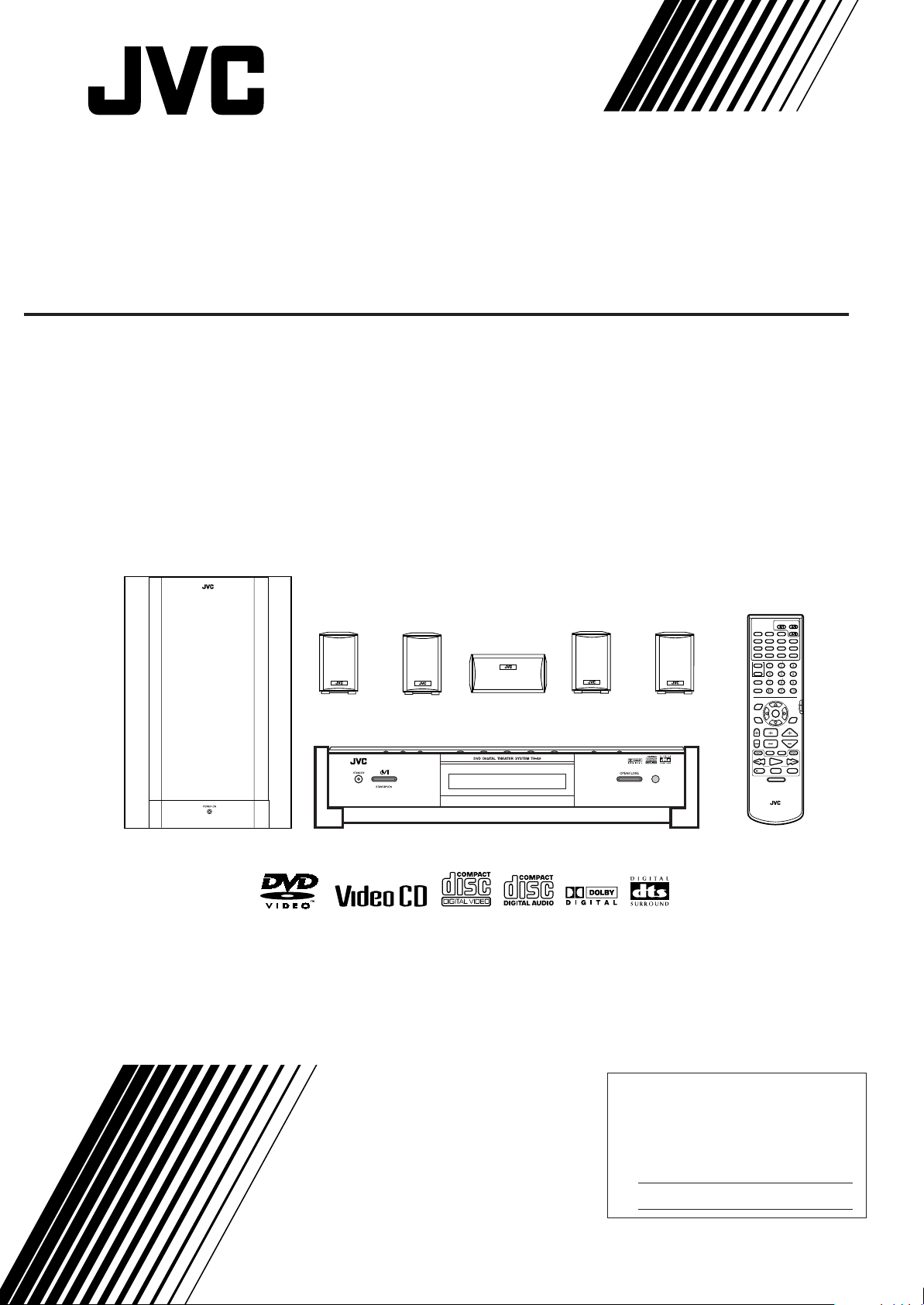
DVD DIGITAL THEATER SYSTEM
TH-A9
Consists of XV-THA9, SP-PWA9, SP-XCA9, and SP-XSA9
SP-XSA9
SP-XCA9
SP-XSA9
AUX
TITLE
ZOOM
CONTROL
VCR
TV
SLEEP
SETTING
TV RETURN FM MODE
PLAY
MODE
THEATER
POSITION
CHANNELTV VOL VOLUME
/REW
REC
STANDBY/ON
AUDIOTV/CATV/DBS
VCR
DVD
FM/AM
DECODE
SUBTITLE
AUDIO
TIME
DIGEST
DISPLAY
CHOICEANGLERETURN
SOUND
SUBWOOFER
EFFECT
CENTER
TEST
REAR-L
REAR-R
100+
AUDIO/
TV/VCR
CAT/DBS
ENTER
DSP
MODE
TV/VIDEO
MUTING
F.SEARCHB.SEARCH
FF
PLAY
UPDOWN
TUNING
PAUSE
STOP
STROBEMEMORY
DVD MENU
SP-PWA9
XV-THA9
INSTRUCTIONS
RM-STHA9J
DVD THEATER SYSTEM
For Customer Use:
Enter below the Model No. and Serial
No. which are located either on the rear,
bottom or side of the cabinet. Retain this
information for future reference.
Model No.
Serial No.
LVT0562-002A
[J]
Page 2
EnglishEnglishEnglishEnglishEnglishEnglishEnglish
Warnings, Cautions and Other
CAUTION
RISK OF ELECTRIC
SHOCK
DO NOT OPEN
CAUTION: TO REDUCE THE RISK OF ELECTRIC SHOCK
DO NOT REMOVE COVER (OR BACK)
NO USER SERVICEABLE PARTS INSIDE
REFER SERVICING TO QUALIFIED SERVICE PERSONNEL.
The lightning flas h w ith arro whead symbol,
within an equilateral triangle is intended to
alert the user to the presence of uninsulated “dangerous voltage” within the product’s enclosure that may be of sufficient
magnitude to constitute a risk of electric
shock to persons.
The exclamation point within an equilateral
triangle is intended to alert the user to the
presence of important operating and maintenance (servicing) instructions in the literature accompanying the appliance.
For U.S.A.
This equipment has been tested and found to comply with
the limits for a Class B digital device, pursuant to Part 15 of
the FCC Rules. These lim its are desi gned to provide reasonable protection against harmful interference in a residential
installation. This e qui pm en t ge nera tes , us es , a nd c an rad iate
radio frequency energy and, if not installed and used in
accordance with th e in st ruc tions, may cause harmful in terfe r ence to radio communications. However, there is no guarantee that interference will not occur in a particular installation.
If this equipment does cause harmful interference to radio or
television reception, which can be determined by turning the
equipment off a nd on , the user is enco ura ged to try to correct
the interference by one or more of the following measures:
WARNING: TO REDUCE THE RISK OF FIRE
OR ELECTRIC SHOCK, DO NOT EXPOSE THIS
APPLIANCE TO RAIN OR MOISTURE.
Caution — POWER switch!
Disconnect the mains plug to shut the power off completely.
The POWER switch in any position does not disconnect the
mains line. The power can be remote controlled.
IMPORTANT FOR LASER PRODUCTS
1. CLASS 1 LASER PRODUCT
2.
DANGER:
lock failed or defeated. Avoid direct exposure to beam.
3.
CAUTION:
serviceable parts inside the unit; leave all servicing to
qualitied service personnel.
CAUTION
To reduce the risk of electrical shocks, fire, etc.:
1. Do not remove screws, covers or cabinet.
2. Do not expose this appliance to rain or moisture.
Invisible laser radiation when open and inter-
Do not open the top cover. There are no user
G-1
Page 3

■■
Table of Contents
Getting Started.. ... ... .... .......................................... 2
Important cautions................................................................2
Safety precautions.................................................................2
Checking the supplied accessories........................................ 2
System outline ...................................................... 3
Installation............................................................. 4
To hang satellite speakers from the wall ..............................4
About discs ........................................................... 5
Playable disc types................................................................5
Disc structure........................................................................5
Video CDs with Playback Control function .........................5
Connections..........................................................6
Connecting the FM and AM antennas........................ .... ... ...6
Connecting the powered sub-woofer....................................6
Connecting the TV................................................................6
Connecting the TV with the component video input jacks... 7
Connecting speakers............................................................. 8
Connecting an audio component...........................................9
Connecting the power cord....................... ......................... .10
Putting batteries in the remote control................................10
Parts Identification ..............................................11
Principles of operation ........................................14
Operation with the remote control................... ...................14
On-screen displays..............................................................15
Preventing screen burn-out with the screen saver [SCREEN
SAVER]..............................................................................16
Basic operat io ns ............... ...................... ... .........17
To turn the system power supply ON and OFF (standby).. 17
To turn TV power ON and OFF.........................................17
Adjusting volume [VOLUME]....................................... ... .17
Sub-woofer volume control and phase setting.................... 18
Muting the sound [MUTING]............... .... ... .... .... ... ............18
Selecting the source to play ................................................18
Changing the decode mode [DECODE]............................. 19
Audio channel display indicator.........................................19
Using the Sleep Timer [SLEEP].........................................20
Using the DSP Modes [DSP MODE] .................................20
Using the DVD player .........................................22
To turn on the system and TV ............................................ 22
To insert a disc.................................................................... 22
To play a disc...................................................................... 23
Pausing................................................................................24
Fast forward and backward.................................. ... ............24
Locating the beginning .......................................................24
Resuming playback.............................................................25
Selecting playback from the DVD menu............................25
Selecting the location to view from the Video CD menu... 26
To specify the title, chapter, or track number for playback 26
To play from the beginning of a title, chapter, or track...... 27
To specify the chapter number for playback
[CHAP. SEARCH] ............................................................. 27
To specify the time for playback [TIME SEARCH]..........28
To select the screen for playback from the digest screen
[DIGEST]............................................................................ 29
To advance the picture one frame at a time........................ 29
Slow-Motion Playback [SLOW]......................... ... ............30
To display Continuous Photos
[STROBE] ..........................................................................30
Zooming a scene [ZOOM]........................ ... .... .... ...............31
Changing the Subtitle Language [SUBTITLE]..................31
Changing the audio language or sound [AUDIO].............. 32
Changing the audio channel [AUDIO]...............................32
Viewing from Multiple Angles [ANGLE].......................... 33
Selecting the Picture Character [THEATER POSITION].. 34
Repeating a current title, chapter or track, or all tracks
[REPEAT].................... .... ... .......................... ... .... .... ...........34
Repeating a desired part [A-B REPEAT]............................35
Programming the Playing Order [PROGRAM]..................36
Random Play [RANDOM] ..................................................37
To check the DVD function status......................................3 7
To check the disc information.............................................38
To check the time information ............................................38
Receiving radio broadcasts.................................40
Tuning in stations manually ................................................40
Using preset tuning............................. ......................... .... ... .40
Selecting the FM reception mode..................... ...................41
Beat cut................................................................................41
Preference settings.............................................42
Using the preference setting menus.....................................42
LANGUAGE MENU settings...............................43
Choosing menu language...................... .......................... ... .43
Choosing audio language......................................... ...........43
Choosing subtitle language .................................................43
Choosing on-screen language................ .... .... ......................43
DISPLAY MENU settings... ... ... ... ........................4 4
Select monitor type......................... .... ......................... .... ... .44
Screen saver settings ...........................................................44
On-screen guide settings .....................................................44
SYSTEM MENU setting......................................45
AUTO STANDBY.................................... ......................... .45
RESUME........................................ .... ... .......................... ... .45
AV COMPULINK MODE....................................... ... ........45
Limiting playbac k by chi ldr en ................ ... ... ........46
To set Parental Lock for the first time
[PARENTAL LOCK]................................ .... ......................46
To temporarily release the Parental lock.............................47
Amplifier settings.................................................48
Basic operation for setting amplif ier...................................48
Setting balance ....................................................................48
Setting tone..........................................................................49
Setting speaker size.............................................................49
Adjusting delay time...........................................................49
Adjusting crossover.............................................................50
Adjusting LFE attenuator....................................................50
Adjusting dynamic range.....................................................50
Sound settings ....................................................51
Adjusting sub-woofer level .................................................51
Adjusting speaker level .......................................................51
Adjusting DSP effect...........................................................52
AV COMPU LINK remote control system............53
Connection and setup..........................................................53
Operation.............................................................................54
Operating Other Manufacturers’ Video
Equipment...........................................................55
Care and handling of discs..................................57
How to handle discs ............................................................57
Troubleshooting ..................................................58
Specifications......................................................59
EnglishEnglishEnglishEnglishEnglishEnglishEnglish
1
Page 4
■■
Getting Started
Important cautions
EnglishEnglishEnglishEnglishEnglishEnglishEnglish
Installation of the unit
• Select a place whic h is level, dry and ne ither too hot nor t oo
cold between 5°C and 35°C (41°F and 95°F).
• Leave sufficient distance between the unit and the TV.
• Do not use the unit in a place subject to vibrations.
Power cord
• Do not handle the power cord with wet hands!
• A small amount of power 1.3 W is al ways cons umed whil e the
power cord is connected to the wall outlet. (center unit only)
• When unplugging the unit from the wall outlet, always pull the
plug, not the power cord.
To prevent malfunction of the unit
• There are no user-serviceable parts inside. If anything goes
wrong, unplug the power cord and consult your dealer.
• Do not insert any metallic object into the unit.
• Do not use any non-standard shape disc available on the market, because it may damage the unit.
• Do not use a disc with tape, seals, or paste o n it, becau se dam age to the unit may result.
Note about the copyguard system
• The DVD disc is protected by the copyguard system. When you
connect the unit to your VCR directly, the copyg uard system
activates and the pictu re may not be played back correctly.
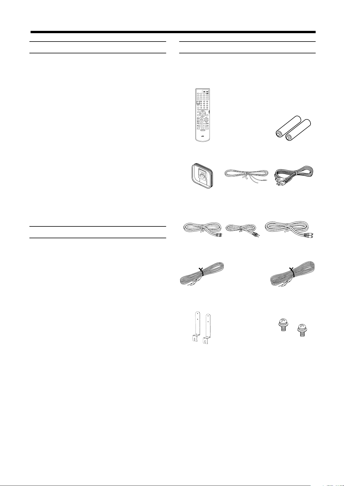
Checking the supplied accessories
Check to be sure you have all of the following items, which are
supplied with the unit.
The number in the parentheses indicates quantity of the pieces supplied.
STANDBY/ON
AUDIOTV/CATV/DBS
VCR
DVD
AUX
FM/AM
DECODE
SUBTITLE
TITLE
AUDIO
TIME
DIGEST
ZOOM
DISPLAY
CHOICEANGLERETURN
SOUND
SUBWOOFER
EFFECT
CONTROL
VCR
CENTER
TEST
TV
REAR-L
SLEEP
REAR-R
SETTING
TV RETURN FM MODE
100+
AUDIO/
TV/VCR
PLAY
MODE
CATV/DBS
ENTER
THEATER
DSP
POSITION
MODE
CHANNELTV VOL VOLUME
TV/VIDEO
MUTING
F.SEARCHB.SEARCH
/REW
FF/
PLAY
UPDOWN
TUNING
PAUSE
REC
STOP
STROBEMEMORY
DVD MENU
RM-STHA9J
DVD THEATER SYSTEM
Remote cont rol (1) Batteries (2)
AM Loop Antenna
(1)
FM Antenna (1) AC Power Cord (1)
Safety precautions
Avoid moisture, water and dust
Do not place your unit in moist or dusty places.
Avoid high temperatures
Do not expose the unit to dir ec t sunl igh t or plac e it nea r a heati ng
device.
When you’re away
When away on travel or otherwise for an extended period of time,
remove the plug from the wall outlet.
Do not block the vents
Blocking the vents may damage the unit.
Care of the cabinet
When cleaning the unit, use a soft cloth and follow the relevant instructions on the use of chemically-coated clo ths. Do not use benzene, thinner or other organ ic solvents and disinfectants. These
may cause deformation or discoloring.
If water gets inside the unit
Turn off the power switch and remove the plug from the wall outlet, then call the st ore where you ma de your purcha se. Using the
unit in this state may cause a fire or electrical shock.
Video Cable (1) Compulink Cord (1) System Cable (1)
Speaker Cord 5 m
(16.4 ft) (3)
Satellite speaker wall
Speaker Cord 10m
(32.8 ft) (2)
Screws (2)*
bracket (2)*
* Speaker wall brackets and screws are packed
together with the satellite speakers.
Avoid getting your hand caught in the disc
cover
Getting caught may injure your hand.
2
Page 5
■■
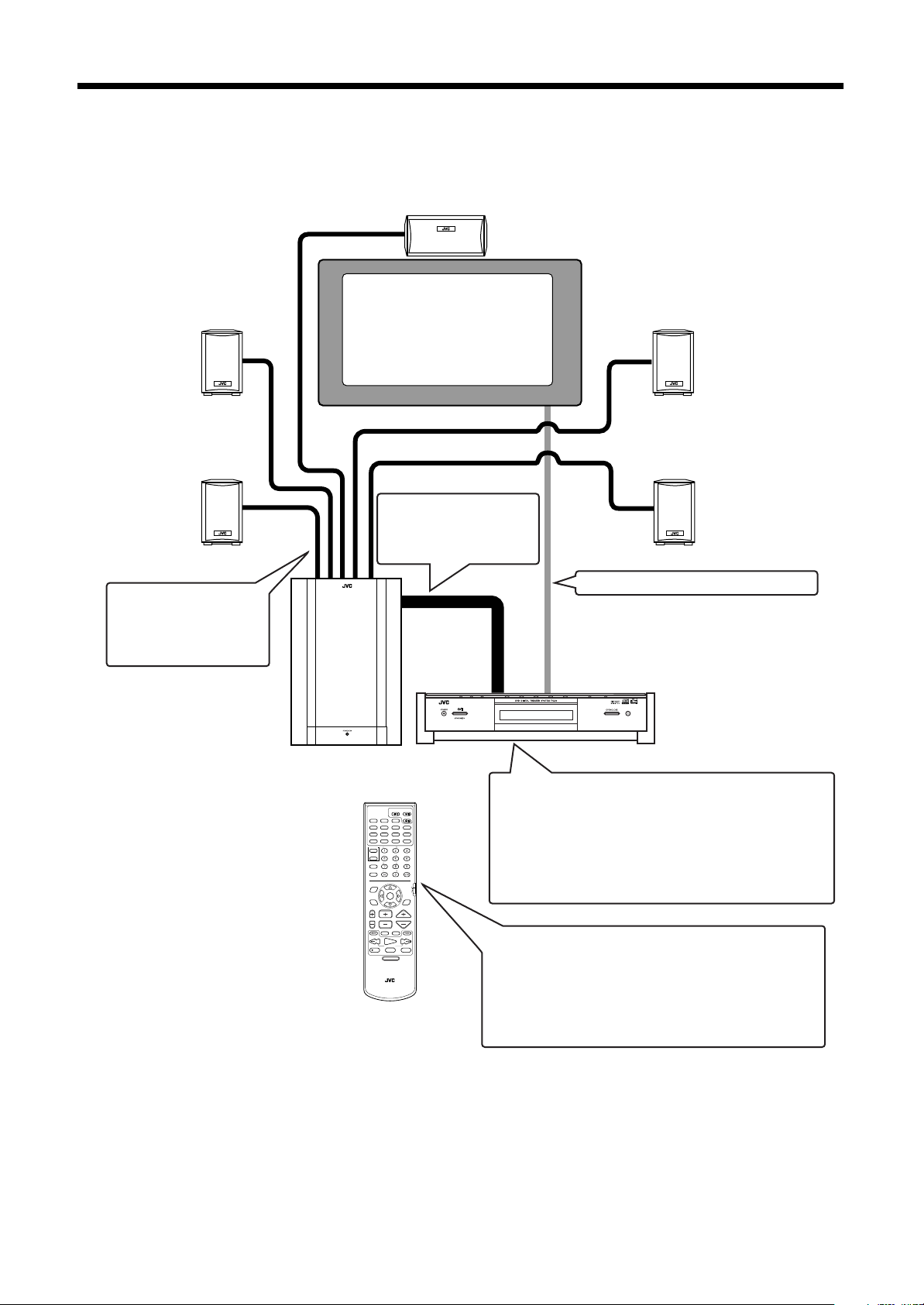
System outline
This system consists of the unit contain ing a DVD play er, a radio, a nd a p re-am p, as well as the p owered sub -woofer, the cen ter speaker,
and four satellite speaker units.
It provides a fully functional DVD theater system by simply connecting to a TV set.
Center speaker
(SP-XCA9)
Front left speaker
Satellite speaker
(SP-XSA9)
Rear left speaker
Satellite speaker
(SP-XSA9)
The center speaker and the
satellite speakers are connected to the powered subwoofer.
Powered sub-woofer
(SP-PWA9)
TV
The center unit and powered sub-woofer are connected with the system
cable.
Front right speaker
Satellite speaker
(SP-XSA9)
Rear right speaker
Satellite speaker
(SP-XSA9)
The TV is connected to the center unit.
Center unit (XV-THA9)
AUX
TITLE
ZOOM
CONTROL
VCR
TV
SLEEP
SETTING
TV RETURN FM MODE
PLAY
MODE
THEATER
POSITION
CHANNELTV VOL VOLUME
/REW
REC
DVD THEATER SYSTEM
STANDBY/ON
AUDIOTV/CATV/DBS
VCR
DVD
FM/AM
DECODE
SUBTITLE
AUDIO
TIME
DIGEST
DISPLAY
CHOICEANGLERETURN
SOUND
SUBWOOFER
EFFECT
CENTER
TEST
REAR-L
REAR-R
100+
AUDIO/
TV/VCR
CATV/DBS
ENTER
DSP
MODE
TV/VIDEO
MUTING
F.SEARCHB.SEARCH
FF/
PLAY
UPDOWN
TUNING
PAUSE
STOP
STROBEMEMORY
DVD MENU
RM-STHA9J
Contains a DVD player, radio, and preamp (volume control, tone control), tog e the r with a Dolby digital decode r
and DTS digital surround decoder for Dolby Surround
and DTS Digital Sur round effects.
For some music software, the DAP mode offers the expanded sound field.
This system is capable of most operations.
It may also be used to operate JVC TVs and VCRs, as well
as TVs and VCRs from other m a nu f a cturers. Note that the
remote control unit must be programmed with the correct
EnglishEnglishEnglishEnglishEnglishEnglishEnglish
settings when using products from other manufacturers.
3
Page 6
■■
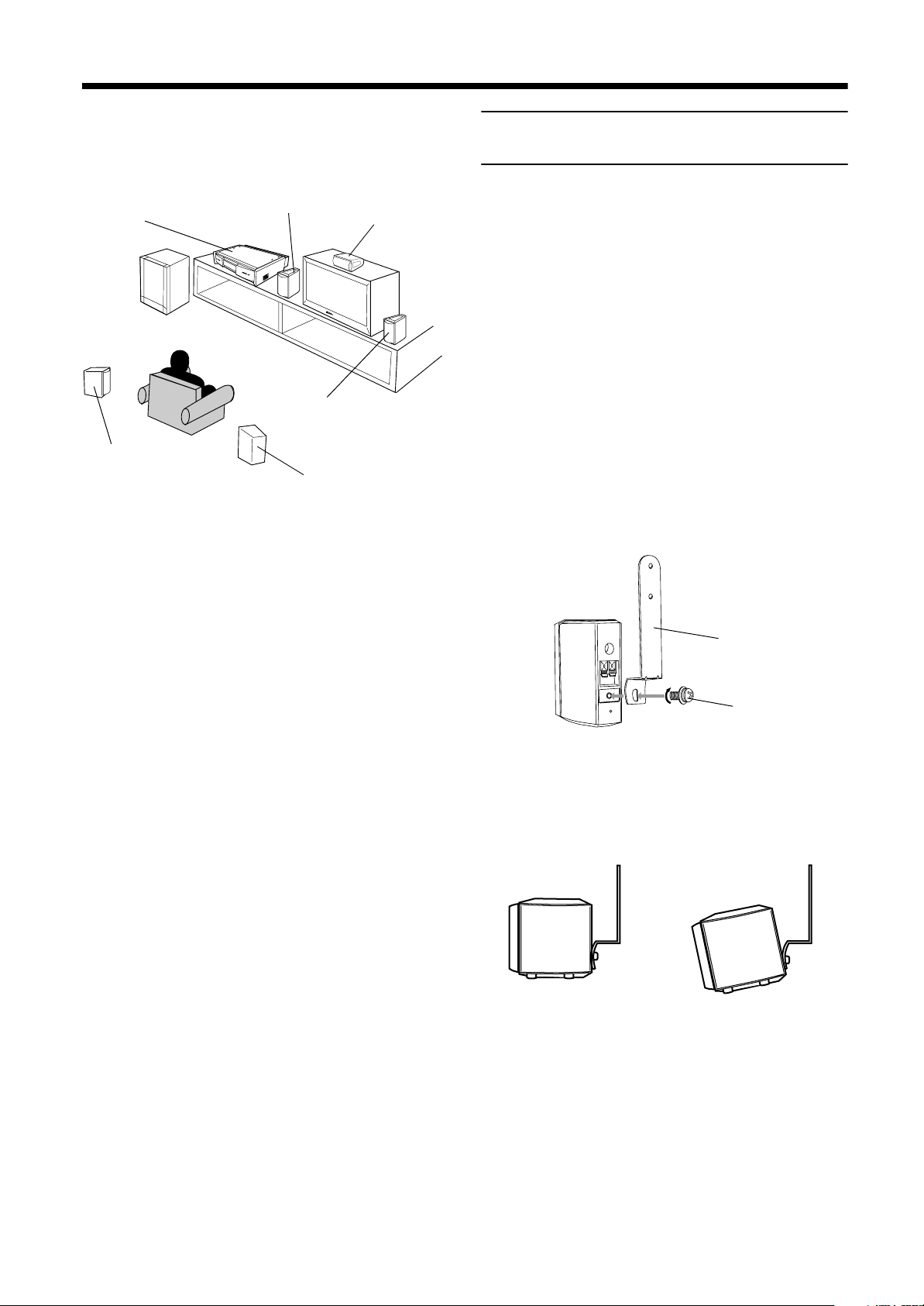
Bracket
Screw
Normal position
Tilting the speaker
Installation
The following shows an example of the system installation.
EnglishEnglishEnglishEnglishEnglishEnglishEnglish
System setting example
Satellite speaker
Center unit
Powered
sub-woofer
Satellite speaker
(rear left speake r)
(front left speaker)
Satellite speake r (front
right speak er)
Satellite speaker
(rear right speaker )
The rear speakers are placed
behind the listening posi tio n.
Center speaker
To hang satellite speakers from the
wall
Use the supplied bracket to fix satellite speakers to the wall.
CAUTION: ATTACHING THE BRACKETS
ON THE WALL
When attaching the brackets on the wall, have them
attached to the wall by a qualified person.
DO NOT attach the brackets on the wall by yourself to
avoid an unexpected damage of their falling from the
wall, caused by incorrect attachment or weakness in
the wall.
Location of attachment to wall:
Care is required in selecting a location for attaching
satellite speakers to the wall. Injury to personnel, or
damage to equipment, may result if the speakers are
attached in a location which interfe res with daily activities.
Attaching speakers to the bracket
1
Use the screw supplied to attach the speaker
to the bracket.
CAUTIONS:
• For safety reasons, always ensure that there is sufficient place behind the powered sub-woofer.
• If the front and rear speakers are placed on the furniture etc., always ensure that they are level.
2
Adjusting the angle of the satellite speakers
The angle of the speaker may be adjusted along the channel in
the bracket.
When adjusting the angle, loosen the scre w slightly, make the
adjustment, and then tighten the screw firmly.
4
CAUTION:
If the screw is not tightened firm ly, it may c ause injury
to personnel or damage to equipment.
Page 7
■■
About discs
Playable disc types
Playable and non-playable disc types are as follows:
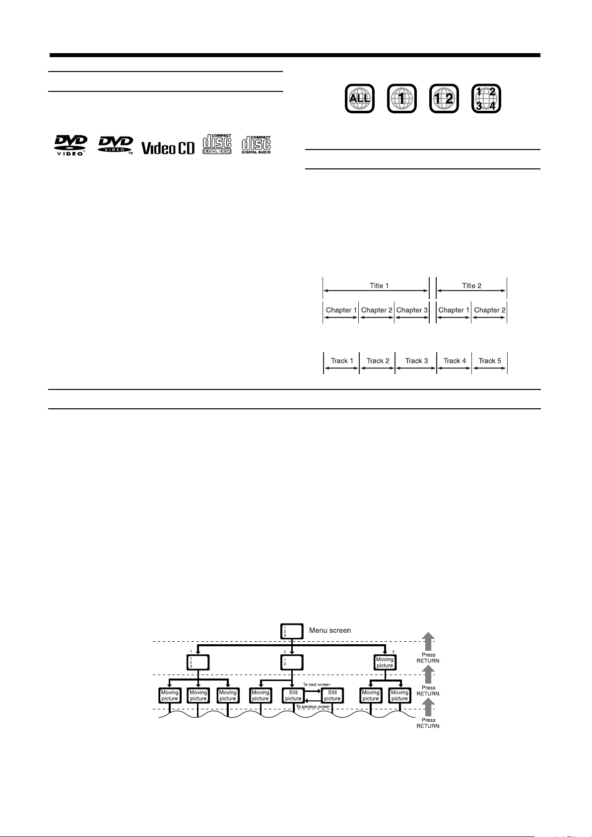
Playable discs
DVD Video CD
The DVD Logo is a trademark.
Non-playable discs
• DVD-ROM • DVD-RAM • DVD-R • DVD-RW
• CD-R*• CD-ROM • PHOTO CD • CD-RW*
* Audio formatted CD-R and CD-RW can be played.
• Playing back discs list as “No n- p la ya ble discs” abov e m a y g e nerate noise and damage speakers.
• Only audio can be played for CD-G, CD-EXTRA and CD
TEXT.
Notes on DVD discs
• DVD players and DVD discs have their own Region Code
numbers. This unit only can play back DVD discs whose
Region Code numbers include “1”.
Audio CD
Examples of playable DVD discs:
• This unit is designed to use the NTSC system. The unit cannot
play back the disc recorded on the PAL system.
Disc structure
A DVD disc is comprised of “titles”, while an Audio CD or Video
CD is comprised of “tracks”. Each title may be divided into some
“chapters”. For example, if a DVD disc contains some movies,
each movie may have its own title number , and each m ovie may be
divided into some chapters. In a DVD karaoke disc, each song usually has its own title number and does not hav e chapters. In gen eral, each title has independent content, while each chapter in the
same title has continuity.
Example: DVD disc
Example: Audio CD/Video CD
Video CDs with Playback Control function
What is Playback Control function?
The Playback Control function, allows you to enjoy menu-driven operation and high-resolution still images which have a resolution four
times greater than moving pi ctures.
• Menu-driven playback
You can interact with the screen us ing a menu display to select and play an entry.
• High-resolution still image display
You can display high-quality images four times clearer than moving pictures.
A selection menu is displayed when you start playing a Video CD with the Playback Control feature. The selection menu shows a list of
numbers for selectio n. Some discs may show moving pictures or a divided screen.
1. When a list of numbers is displayed, selecting a number shows its contents.
2. When “3333” or “SELECT” is displayed on the television screen, pressing this button jumps to the specific picture.
3. When the selection menu is re-displayed after you have played your selection, selecting a number again replays its contents.
(Some discs may show the menu screen several times.)
When ¢ and 4 are shown, pressing “NEXT” or “PREV” can change the selection menu.
4. After playback, press RETURN to go back to the previous screen.
To stop playback, press STOP.
EnglishEnglishEnglishEnglishEnglishEnglishEnglish
Note:
• When a menu is displayed for a long time (about ten minutes), the screen background automatically gets dark to prevent
screen burn-in while the setting is suspended.
5
Page 8
■■
CAUTION
RISK OF ELECTRIC SHOCK
DO NOT OPEN
MAX
MIN
REVERSR
NOMAL
PHASE
SUB WOOFER
CONNECTOR
FROM XV - THA9
FRONT SPEAKERS
CENTER
SPEAKER
REAR SPEAKERS
SPEAKER IMPEDANCE
SPEAKER IMPEDANCE
CAUTION :
SPEAKER IMPEDANCE
CAUTION :
CAUTION :
LEFT
RIGHT
VOLUME
AV
COMPU LINK
AUX IN
ANTENNA
AM
LOOP
AM EXT
COMPONENTS-VIDEOVIDEO
VIDEO OUT
Y PB PR
RL
CONNECTOR
TO SP-PWA9
CONNECTOR
TO SP-PWA9
CONNECTOR
FROM XV - THA9
Center unit (XV-THA9)
Ensure that the £ mark on the
plug faces down.
System cable
(supplied)
Ensure that the £ mark
on the plug faces to the
right.
Powered sub-woofer
(SP-PWA9)
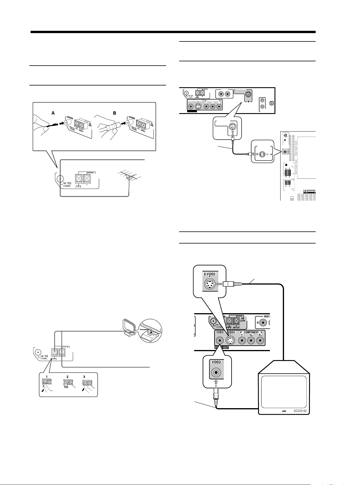
S-video cable (not supplied)
Connect to the TV if it has an S-video input (for higher image quality). Connect
the cables with the ∞ mark facing up.
Center unit (XV-THA9)
Video cable
(supplied)
To composite
video input
To S-video
input
Connections
CAUTION:
EnglishEnglishEnglishEnglishEnglishEnglishEnglish
• Make all connection before plugging the system in
an AC outlet.
Connecting the FM and AM antennas
FM antenna connections
A.
Extend the supplled FM ant enna horizontally.
ANTENNA
B.
A.Using the supplied FM antenna
The FM antenna provided can be connected to the FM 75 Ω COAXIAL terminal as temporary measure.
FM Antenna
AM
LOOP
AM EXT
Outdoor FM Antenna Cable
Connecting the powered sub-woofer
Use the supplied system cable to connect the powered sub-woofer
(SP-PWA9).
CAUTUON:
Use the system cable provided for attaching the center unit and the sub-woofer.
B.Using the standard type connector (Not sup-
plied)
A standard type connector should be connected to the FM 75 Ω
COAXIAL terminal.
Note:
• If reception is poor, connect the outdoor antenna.
Before attaching the 75 Ω coaxial cabl e (the kind with a
round wire going to an outdoor antenna), disconnect the
supplied FM antenna.
AM antenna connections
Turn the loop until you have the best reception.
ANTENNA
Notes:
• Make sure the antenn a cond uctors do no t touch any o ther
terminals, connecting cords and power cord. This could
cause poor reception.
• If reception is poor, connect an outdoor single vinyl-covered wire to the AM EXT terminal. (Keep the AM loop antenna connected.)
6
AM Loop Antenna
AM
LOOP
AM EXT
Outdoor single vinyl-covered wire
Connecting the TV
Connect the TV to view video images from the unit.
Page 9
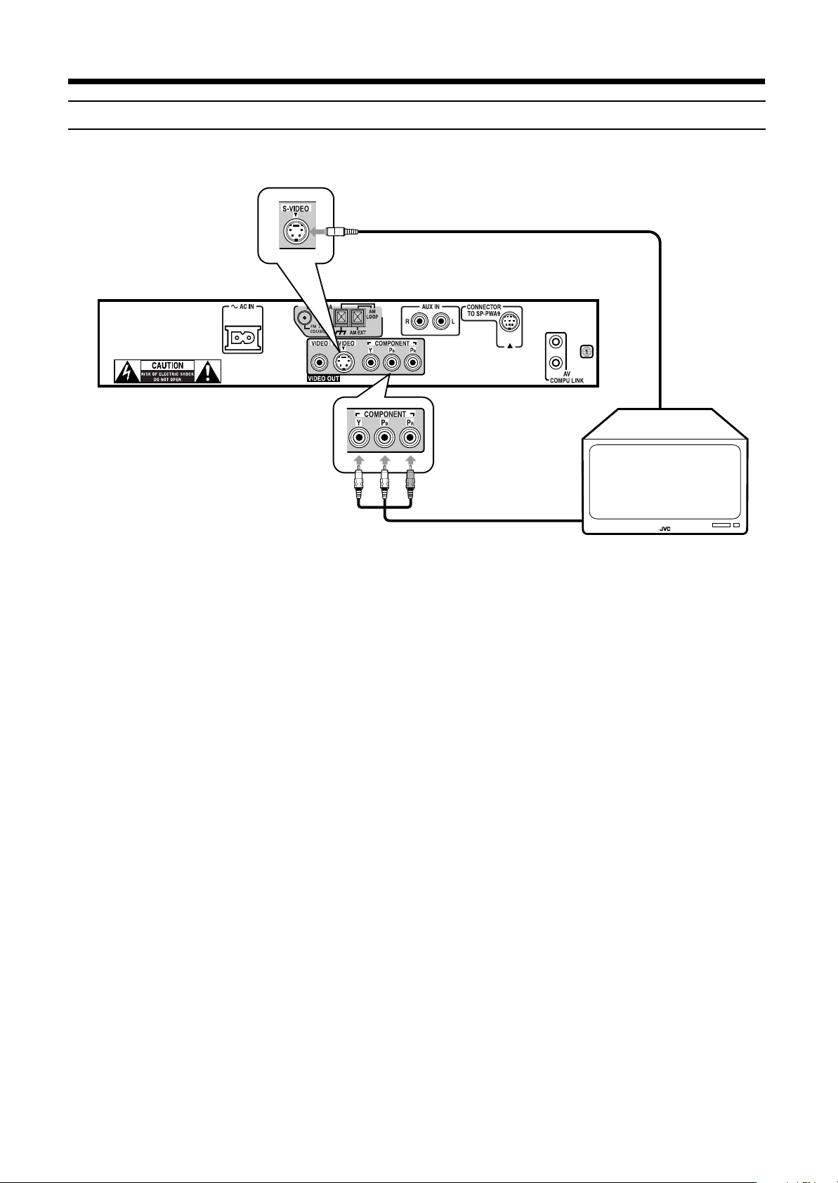
Connecting the TV with the component video input jacks
Connect the TV with the component video input jacks to view high quality picture.
S-video cable (not supp lie d)
Connections
To S-video
input
Green
Blue
• Connect “Y” to “Y”, “PB” to “PB”, and “PR” to “PR” correctly.
Red
Component video cab le
(not supplied)
To component
video input
Note:
• When the component video input jacks of the TV are of the BNC type, use an adapter to convert the pin jacks to BNC jacks
(not supplied).
• Connect the S-video cable (not supplied). Otherwise, some functions of the TV may not work.
EnglishEnglishEnglishEnglishEnglishEnglishEnglish
7
Page 10
Connections
CAUTION
RISK OF ELECTRIC SHOCK
DO NOT OPEN
MAX
MIN
REVERSR
NOMAL
PHASE
SUB WOOFER
CONNECTOR
FROM XV - THA9
FRONT SPEAKERS
CENTER
SPEAKER
REAR SPEAKERS
SPEAKER IMPEDANCE
SPEAKER IMPEDANCE
CAUTION :
SPEAKER IMPEDANCE
CAUTION :
CAUTION :
LEFT
RIGHT
VOLUME
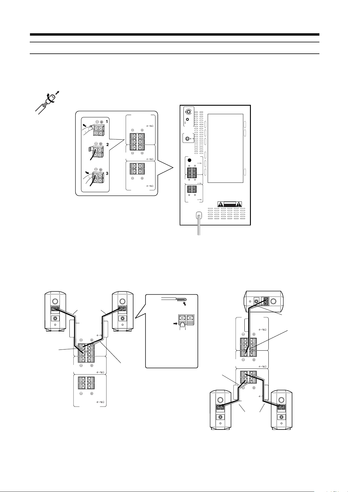
Connecting speakers
EnglishEnglishEnglishEnglishEnglishEnglishEnglish
Connect the satellite speakers and center speaker to the terminals on the powered sub-woofer using the speaker cords supplied.
Labels are attached to the speaker cords to indicate the speaker and termi nal to which each is to be connected.
• The four satellite speakers may be used at either front or rear.
• Ensure that the left a nd ri ght speak ers a re co nnect ed t o l eft a nd ri ght respect ive ly, an d that t hey are conne ct ed wi th the corre ct polarity
(+ve, –ve). The white speaker cord connects to the + terminal, and the black speaker cord connects to the – terminal.
Twist and remove the insulation at the end of each speaker cord.
FRONT SPEAKERS
SPEAKER IMPEDANCE
CAUTION :
LEFT
RIGHT
CENTER
SPEAKER
CAUTION :
SPEAKER IMPEDANCE
Connecting the front speakers
Connect the right speaker to the FRONT SPEAKERS RIGHT t erminal.
Connect the left speaker to the FRONT SPEAKERS LEFT terminal.
CAUTION :
SPEAKER IMPEDANCE
REAR SPEAKERS
Connecting the rear and center speakers
Connect the right rear speaker to the REAR SPEAKERS RIGHT
terminals.
Connect the left rear speaker to the REAR SPEAKERS LEF T terminals.
Connect the center speaker to the CENTER SPEAKER terminals.
Front right speaker
Front left speaker
Speaker cord
(5 m) (16.4 ft)
FRONT RIGHT
FRONT SPEAKERS
SPEAKER IMPEDANCE
CAUTION :
FRONT LEFT
Fold the end of the cord to
avoid short-circuit . Then,
Black
LEFT
RIGHT
while pushing the lever of
the speaker terminal, insert the fold ed end of the
cord into the term inal.
CENTER
SPEAKER
CAUTION :
SPEAKER IMPEDANCE
White
Black
Rear right speaker
CAUTION :
SPEAKER IMPEDANCE
REAR SPEAKERS
Note:
• Mixing up the polarity of the speaker cords can reduce the stereo effect and sound quality.
Center speaker
FRONT SPEAKERS
CENTER
SPEAKER IMPEDANCE
CENTER
SPEAKER IMPEDANCE
SPEAKER
REAR RIGHT
CAUTION :
SPEAKER IMPEDANCE
REAR SPEAKERS
Speaker cord
(10 m) (32.8 ft)
CAUTION :
LEFT
RIGHT
CAUTION :
REAR LEFT
Rear left speaker
Speaker cord
(5 m) (16.4 ft)
White
8
Page 11
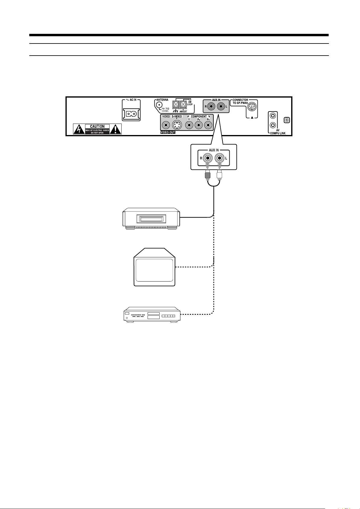
Connecting an audio component
You can connect an analog au dio component, such as VCR, TV and MD recorder to this system.
Refer also to the manuals supplied with your components.
Use the cable with RCA pin plugs (not supplied).
Connect the white plug to the left jack, and the red plug to the right jack.
Connections
VCR
TV
MD Recorder
Audio output
Audio output
Audio output
CAUTION:
If you connect a sound-enhancing device suc h as a graphic equalizer between the sourc e components and the center unit, the sound output through this system may be distorted.
EnglishEnglishEnglishEnglishEnglishEnglishEnglish
9
Page 12
Connections
123
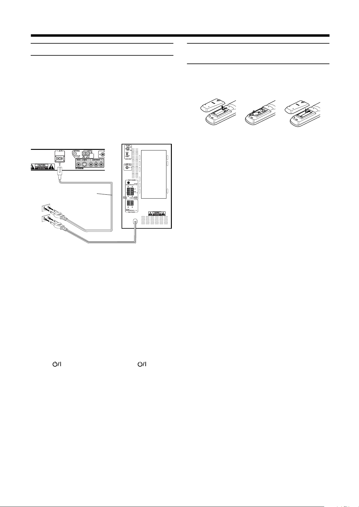
Connecting the power cord
EnglishEnglishEnglishEnglishEnglishEnglishEnglish
Before plugging th e center unit and powered sub-woofer into an
AC outlets, make sure that all connections have been made.
Plug the power cord into an AC outlet.
The red STANDBY lamp on the center unit lights when the power
cord is plugged in.
Keep the power cord away from the connecting cables and the antenna cable. The po wer cord may cause no ise or screen interfe rence.
We recommend that you use a coaxial cable to connect the FM outdoor antenna, since it is well-shielded against interference.
Center unit
AC power cord
CAUTIONS:
• Do not touch the power cord with wet hands.
• Do not pull on the power cord to unplug the cord.
When unplugging the cord, always grasp the plug
so as not to damage the cord.
Powered sub-w oo f er
Putting batteries in the remote control
Before using the remote control, put two supplied batteries first.
When using the remote control, aim the remote control directly at
the remote senso r on the center unit.
1
On the back of the remote control, remove the
battery cover.
2
Insert batteries. Make sure to match the
polarity: (+) to (–).
3
Replace the cover.
• If the range or effectiveness of the remot e control decreases,
replace the batteries. Use two R6P (SUM-3)/AA (15F) type
dry-cell batteries.
CAUTIONS:
Follow these precautions to avoid leaking or cracking
cells:
• Place batteries in the remote control so they match
the polarity: (+) to (–).
• Use the correct typ e o f batteries. Batteries that loo k
similar may differ in voltage.
• Always replace both batteries at the same time.
• Do not expose batteries to heat or flame.
Notes:
• The preset settings such as preset ch annel and sound adjustment may be erased in a few days in the following cases:
– When you unplug the power cord.
– When a power failure occurs.
• The speakers will not produce any sound if the powered
sub-woofer power cord is removed from the AC outlet
while the c enter unit is turned on.
In this case power will not come on even when the powered sub-woofer power cord is plugged in the AC outlet.
Press on the center unit, or AUDIO on the remote control to turn power on. This will turn the powered
sub-woofer on and sound will be emitted from the speakers.
10
Page 13
■■
Become familiar with the button s and con trol s on th e cen ter un it an d p owere d sub -woo fe r befo re use. Re fe r to th e pa ges in p arenth eses for
details.
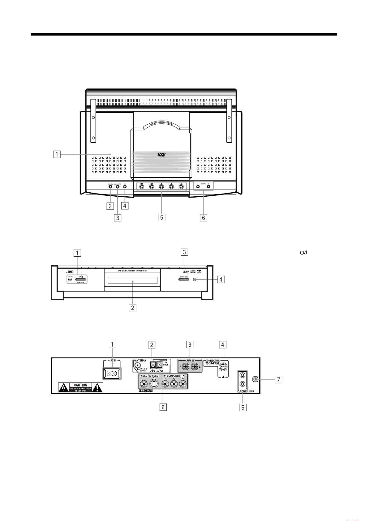
Center unit
Front panel (top view)
Parts Identification
1 Disc cover (22)
2 SOURCE button (18)
3 SURROUND button (21)
4 DSP mode button (21)
5 DVD control buttons (23, 24,
25)
6 VOLUME +/– button (17)
Front panel (front view)
Rear panel
1 AC IN socket (10)
2 Antenna terminals (6)
3 AUX IN terminals (9)
4 Connector for powered sub-woo fer (6)
5 AV COMPU LINK terminals (53)
6 Video output terminals (6, 7)
7 Region code number (5)
1 STANDBY/ON button
and STANDBY lamp (17)
2 Display window
3 OPEN/CLOSE button (22)
4 Remote sensor
EnglishEnglishEnglishEnglishEnglishEnglishEnglish
11
Page 14
Parts Identification
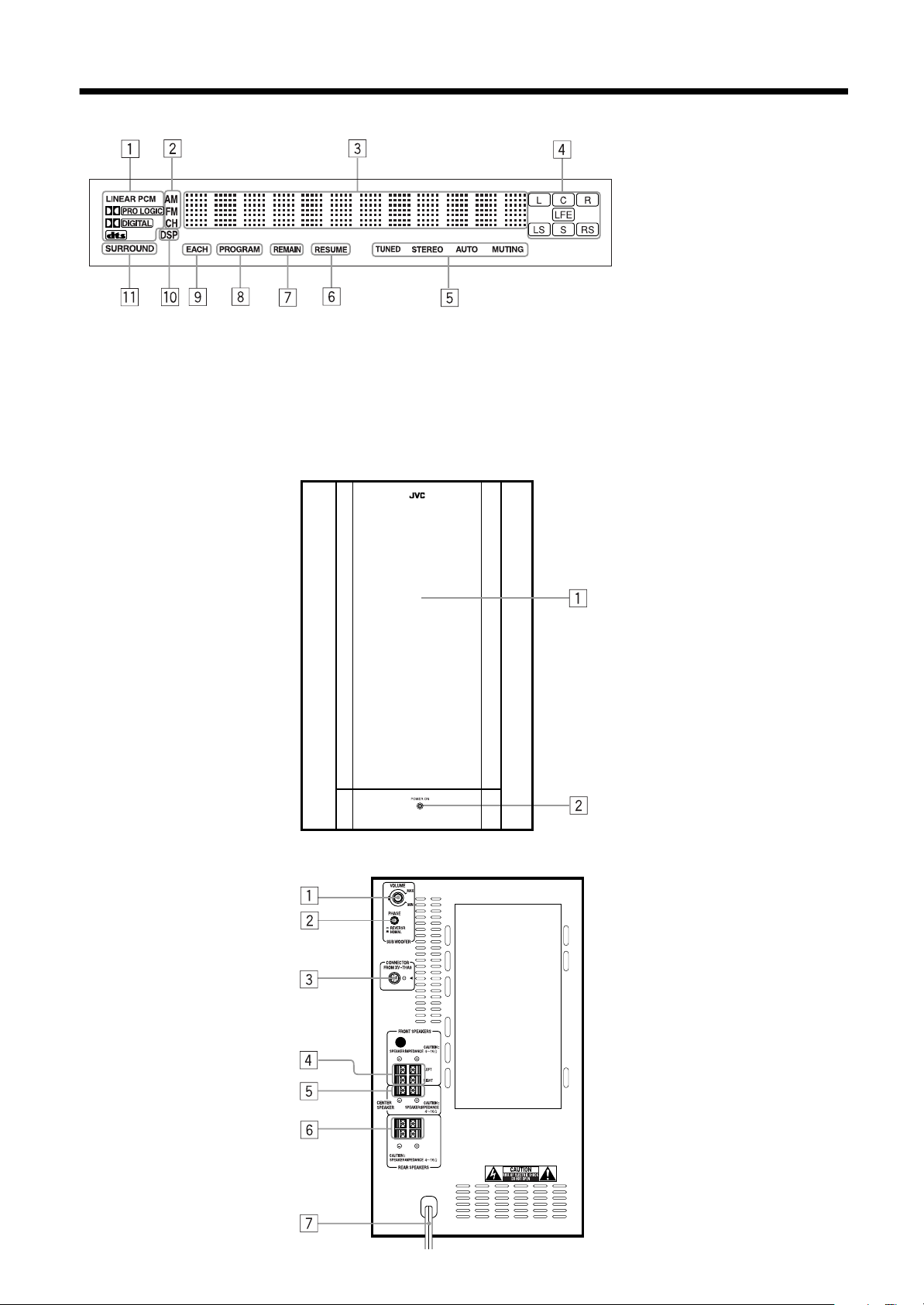
Display window
EnglishEnglishEnglishEnglishEnglishEnglishEnglish
Powered sub-woofer
(Front)
1 Decode mode indicator
2 Radio indicator (40, 41)
3 Multi-information window
Displays time, status
information, etc.
4 Audio channel indicator (19)
5 Radio reception mode indicator
(40, 41)
6 RESUME indicator (25)
7 REMAIN indicator (Timer
indicator) (39)
8 PROGRAM indicator (36)
9 EACH indicator (Timer
indicator) (39)
p DSP indicator (21)
q SURROUND indicator (21)
1 Speaker
2 POWER ON lamp (17)
(Rear)
12
1 VOLUME knob (18)
2 PHASE button (18)
3 Connector for center unit (6)
4 FRONT SPEAKERS
terminals (8)
5 CENTER SPEAKER
terminals (8)
6 REAR SPEAKERS
terminals (8)
7 Power cord (10)
Page 15
Remote controls
FM/AM
AUX
SUBTITLE
TITLE
DIGEST
ZOOM
CONTROL
POSITION
SUBWOOFER
VCR
SLEEP
SETTING
PLAY
MODE
THEATER
CENTER
TV
REAR-L
REAR-R
TV RETURN FM MODE
ENTER
CHANNELTV VOL VOLUME
TV/VIDEO
/REW
PLA Y
TUNING
REC
STOP
DVD MENU
RM-STHA9J
DVD THEA TER SYSTEM
STANDBY/ON
DVD
DECODE
TIME
CHOICEANGLERETURN
MUTING
AUDIOTV/CATV/DBS
VCR
AUDIO
DISPLAY
SOUND
EFFECT
TEST
100+
AUDIO/
TV/VCR
CATV/DBS
DSP
MODE
F.SEARCHB.SEARCH
FF/
UPDOWN
PA USE
STROBEMEMORY
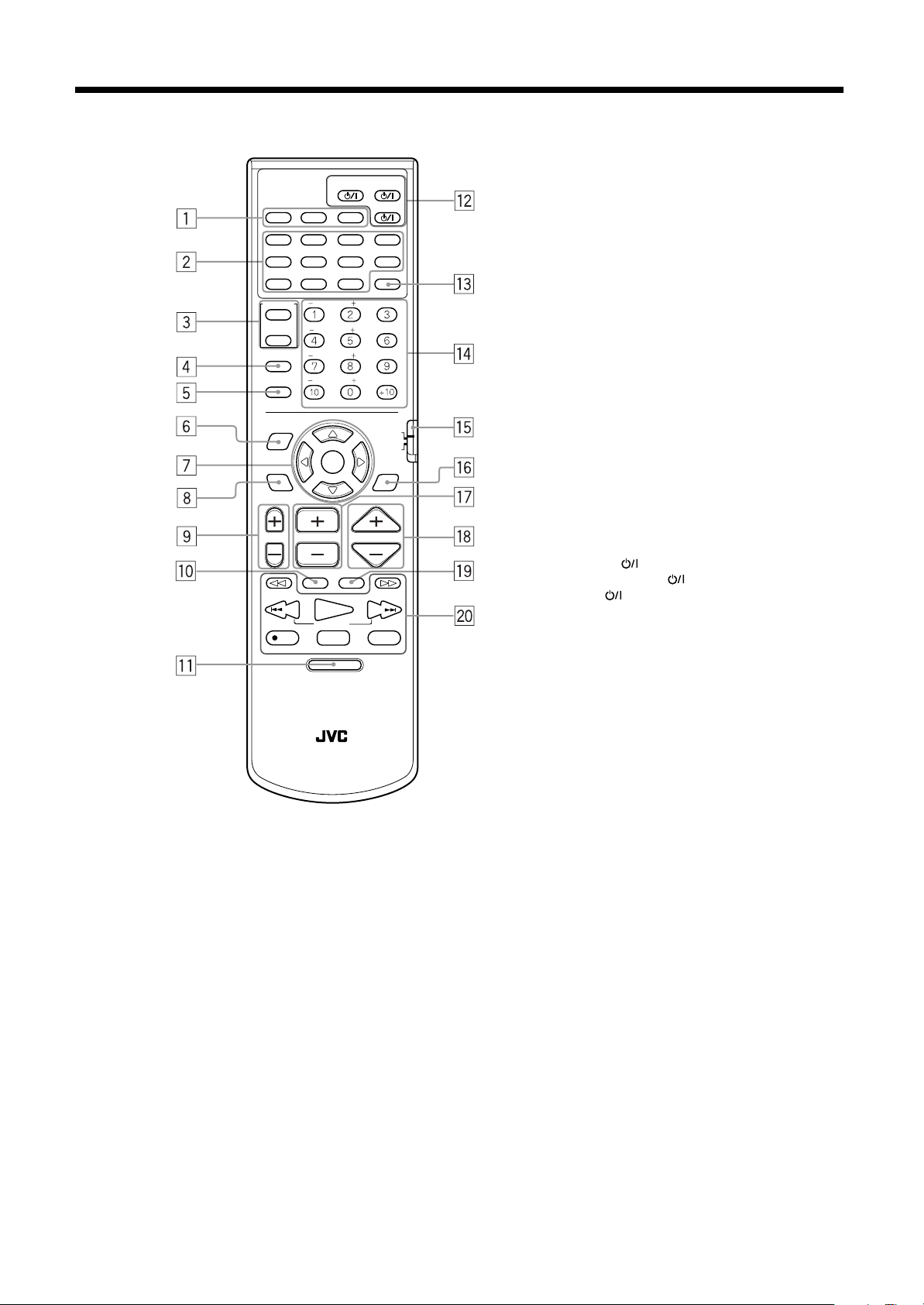
Parts Identification
1 Source selecting buttons (14, 18, 41)
AUX, FM/AM, DVD
2 DVD operating buttons
TITLE (25)
SUBTITLE (31)
DECODE (19)
AUDIO (32)
ZOOM (31)
DIGEST (29)
TIME (38, 39)
DISPLAY (37, 38)
RETURN (26)
ANGLE (33)
CHOICE (42)
3 Control buttons VCR/ TV (55, 56)
4 SLEEP button (20)
5 SETTING button (48)
6 PLAY MODE button (34 , 35, 36, 37)
7 Cursor and ENTER buttons (25)
8 THEATER POSITION button (34)
9 TV VOL +, – button (55)
p TV/VIDEO button (55)
q DV D MENU button (25)
w STANDBY/ON buttons
AUDIO (17, 22)
TV/CATV/DBS (17, 22, 55, 56)
VCR (56)
e SOUND button (51, 52)
r Number buttons
t Remote control mode selector (55)
AUDIO/TV/VCR, CATV/DBS
y DSP MODE button (21)
u CHANNEL +, – button (55, 56)
i VOLUME +, – button (17)
o MUTING button (18)
; Operating buttons (23, 24, 40, 41)
13
EnglishEnglishEnglishEnglishEnglishEnglishEnglish
Page 16
■■
Principles of operation
The system may be operated via the remote control or the buttons on the center unit, or via the menu on the screen.
EnglishEnglishEnglishEnglishEnglishEnglishEnglish
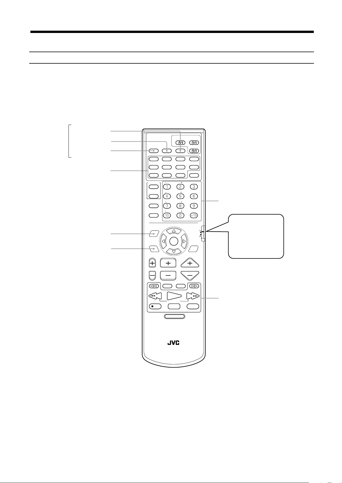
Operation with the remote control
Select the appropriate mode for the remote control when the remote control i s used for operation.
The remote control mode is selected by pressing the source selecting buttons .
Press DVD:
Press FM/AM:
Press AUX:
Source
selecting
buttons
DVD operating buttons
The DVD operation buttons, numb er button s, PLAY MODE b utt on , THEATER POSITION button and operating bu tto ns
operate in DVD mode, enabling operation of the DVD, Audio CD, and Video CD discs.
The number bu ttons and o pera ting bu ttons o pera te in the radio mo de. In Ra dio mode , no thing will be d isp laye d on the TV.
Press to listen to sound inputted to the AUX jacks. In AUX mode, only the VOLUME + and – buttons are operable. Also,
nothing will be displayed on the TV.
DVD button
STANDBY/ON
DVD
DECODE
TIME
CHOICEANGLERETURN
AUDIOTV/CATV/DBS
VCR
AUDIO
DISPLAY
SOUND
EFFECT
TEST
100+
AUDIO/
TV/VCR
CATV/DBS
DSP
MODE
Number buttons
The remote control
mode selector should
be normally set to
AUDIO/TV/VCR position.
FM/AM button
AUX button
PLAY MODE
THEATER POSITION
AUX
TITLE
ZOOM
CONTROL
VCR
TV
SLEEP
SETTING
PLAY
MODE
THEATER
POSITION
FM/AM
SUBTITLE
DIGEST
SUBWOOFER
CENTER
REAR-L
REAR-R
TV RETURN FM MODE
ENTER
CHANNELTV VOL VOLUME
MUTING
TV/VIDEO
/REW
PLA Y
TUNING
REC
STOP
DVD MENU
RM-STHA9J
DVD THEA TER SYSTEM
F.SEARCHB.SEARCH
FF/
PA USE
STROBEMEMORY
UPDOWN
Operating buttons
Note:
• The remote control mo de is affected by th e source selec ting buttons as w ell as the SOUND, VC R, TV buttons, and the re mote
control mode selector.
See pages 51 and 55 for details.
14
Page 17
Principles of operation
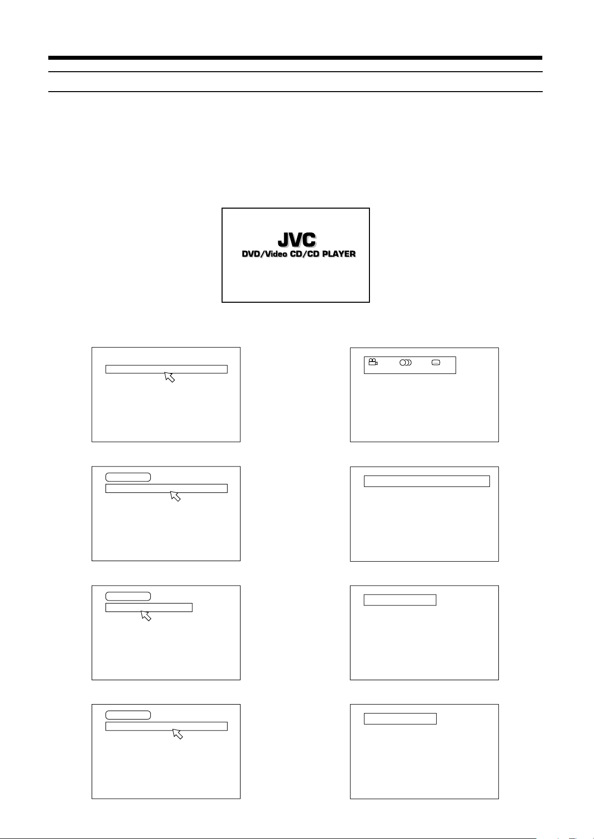
On-screen displays
The center unit provides several on-screen displays.
With some displays, you can set or select preferences or functions, while the others are display-only.
Opening screens
The Opening screen appears aut omatically in some conditions.
At the bottom, the following information are indicated depending on the center unit’s status.
• NOW READING: The center unit is now reading the disc information (TOC).
• REGION CODE ERROR!: The DVD disc loaded cannot be played because the region code of the disc does not match the center unit.
• OPEN: The disc cover is no w opening.
• CLOSE: The disc cover is now closing.
Opening display
NOW READING
Play mode displays
While stopped
REPEAT PROGRAM RANDOM
During DVD playback
DVD CONTROL
REPEAT A-B REPEAT TIME SEARCH CHAP. SEARCH
During Audio CD playback
CD CONTROL
REPEAT A-B REPEAT TIME SEARCH
Status displays
DVD function status
1 / 2 1 / 2 1 / 2
ENGLISH ENGLISH
Disc/time (DVD)
TITLE CHAP. TIME BITRATE
1 25 2:25:25 3.3
Disc/time (Audio CD/Video CD without PBC)
1 0:08
TRACK TIME
EACH
REMAIN
Mbps
During Video CD playback
VCD CONTROL
REPEAT A-B REPEAT TIME SEARCH PBC CALL
Disc/time (Video CD with PBC)
TRACK TIME
1 25:25 PBC
EnglishEnglishEnglishEnglishEnglishEnglishEnglish
15
Page 18
Principles of operation
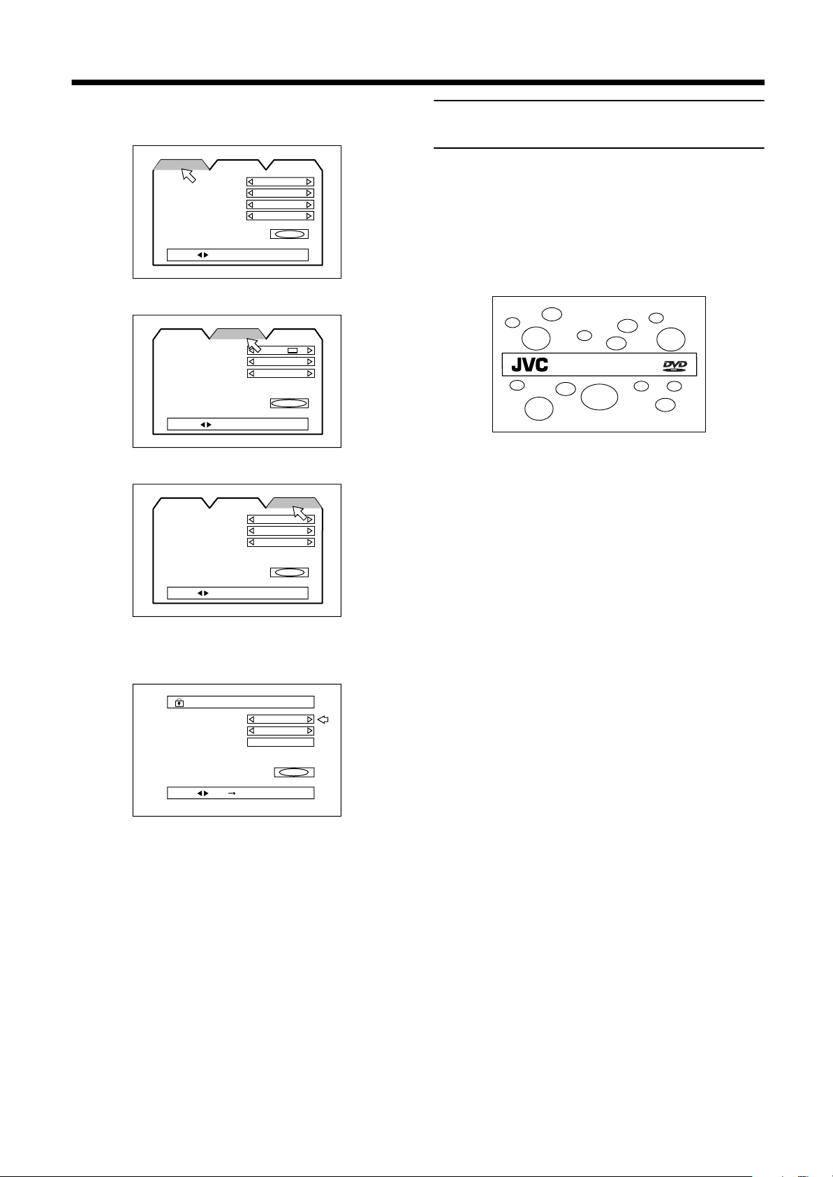
On-screen menus for setting preferences
EnglishEnglishEnglishEnglishEnglishEnglishEnglish
LANGUAGE
LANGUAGE
MENU LANGUAGE
AUDIO LANGUAGE
SUBTITLE
ON SCREEN LANGUAGE
PRESS KEY
DISPLAY
LANGUAGE
MONITOR TYPE
SCREEN SAVER
ON SCREEN GUIDE
PRESS KEY
SYSTEM
LANGUAGE
AUTO STANDBY
RESUME
AV COMPULINK MODE
DISPLAY SYSTEM
ENGLISH
ENGLISH
ENGLISH
ENGLISH
4:3 LB
MODE 2
ON
OFF
OFF
DVD 2
SYSTEM
SYSTEM
DISPLAY
DISPLAY
EXIT
EXIT
Preventing screen burn-out with
the screen saver [SCREEN SAVER]
A television monitor screen may be burned out if a static picture is
displayed for a long time. To preve nt this, the cente r unit a utoma tically activates the screen saver function if a static picture, such as
an on-screen display or menu, is display ed for over 5 minutes.
• Pressing any button on the cente r unit or the remote contro l unit
will release the screen saver function and return to the previous
display.
• You can select one of several screen saver modes available (see
page 44).
DVD/Video CD/CD PLAYER
Note:
• The screen saver does not work during playing back an
Audio CD or whil e stopped a fter played back an Aud io CD.
EXIT
PRESS KEY
On-screen menus for setting parental lock
PARENTAL LOCK
PARENTAL LOCK
Country Code
Set Level
PASSWORD
PRESS KEY ENTER
US
—
----
EXIT
On-screen menus for using discs
The disc status and items are displayed as follows on the on-screen
menus for using the dis c .
16
Page 19
■■
DVD
AUDIOTV/CATV/DBS
STANDBY/ON
VCR
DECODE
SUBTITLE
TITLE
AUDIO
TIME
DIGEST
ZOOM
VCR
CONTROL
SUBWOOFER
EFFECT
CENTER
TEST
DISPLAY
CHOICEANGLERETURN
SOUND
FM/AM
AUX
TV/CATV/DBS
TUNING
UPDOWN
REC
/REW
FF/
PAUSE
TV/VIDEO
MUTING
F.SEARCHB.SEARCH
PLAY
CHANNELTV VOL VOLUME
TV/VCR
CATV/DBS
ENTER
PLAY
MODE
THEATER
POSITION
DSP
MODE
VOLUME + / –
VOLUME + / –
Basic operations
The basic operations for this system are as follows.
IMPORTANT
Check that remote con trol mode selector is set to the approp riate
position:
Set to “AUDIO/TV/VCR” to operate an audio system, TV, or
VCR.
Set to “CATV/DBS” to operate a CATV converter or DBS tuner.
The system will not operate normally while in CATV/DBS mode .
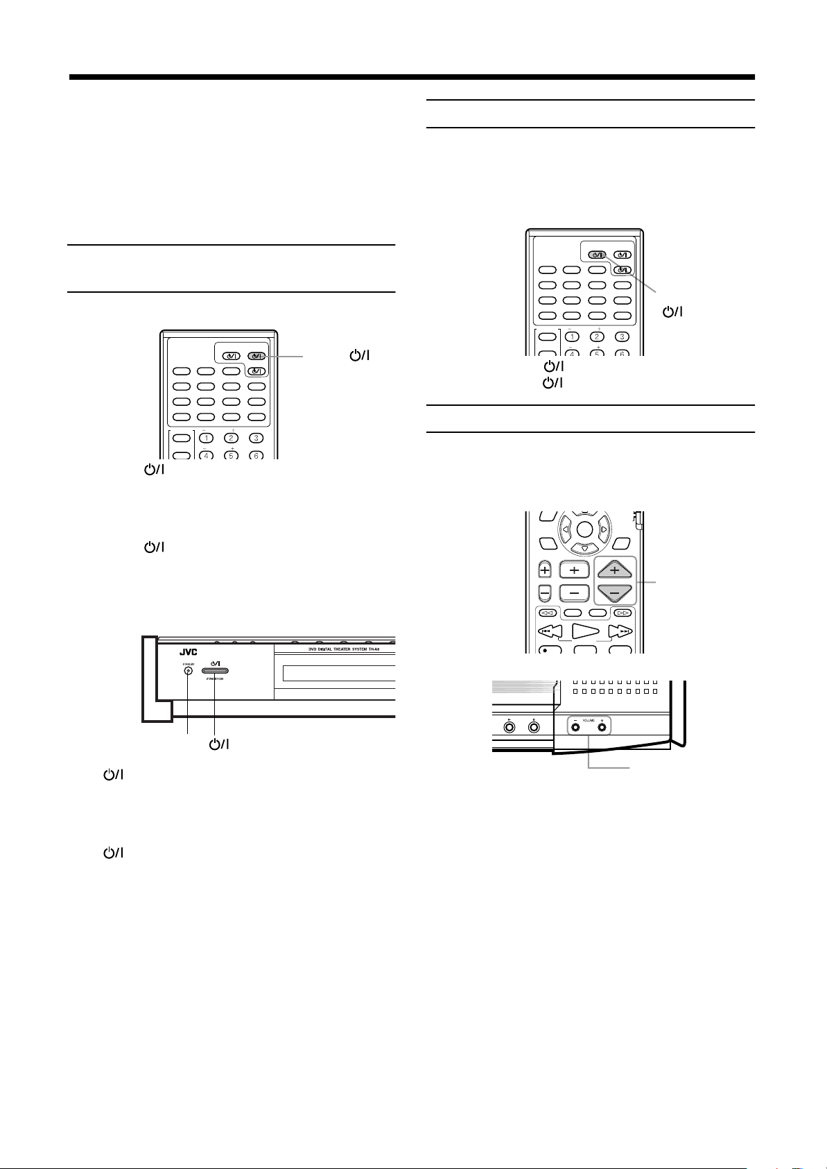
To turn the system power supply
ON and OFF (standby)
From the remote control:
STANDBY/ON
AUDIOTV/CATV/DBS
AUX
TITLE
ZOOM
CONTROL
VCR
TV
FM/AM
SUBTITLE
DIGEST
SUBWOOFER
CENTER
DVD
DECODE
TIME
CHOICEANGLERETURN
VCR
AUDIO
DISPLAY
SOUND
EFFECT
TEST
Press AUDIO to turn power on.
The STANDBY lamp goes off, and the current source name
(DVD, AM or FM station frequency, or AUX) appears on the display window. At this time, the disc cover slides backwards and the
top buttons on the center unit appears.
Press AUDIO again to turn power off (standby).
The STANDBY lamp is lit.
The disc cover slides forward to cover the top buttons on the center
unit and the center unit turns off.
On the center unit:
AUDIO
To turn TV power ON and OFF
JVC TVs may be used as is with the remote co ntrol. TVs from other manufacturers require changes to the transmittable signals before they can be used with the remo te control. See page 5 5 for
details of changing th e transmittable signals.
From the remote control:
Press TV/CATV/DBS to turn power on.
Press TV/CATV/DBS again to turn power off.
Adjusting volume [VOLUME]
The volume level can be adjusted within the range of “0” (minimum) to “80” (maximum).
Common:
From the remote control
STANDBY lamp
Press to turn power on.
The STANDBY lamp goes off, and the current source name
(DVD, AM or FM station frequency, or AUX) appears on the display window. At this time, the disc cover slides backwards and the
top buttons on the center unit appears.
Press again to turn power off (standby).
The STANDBY lamp is lit.
The disc cover slides forward to cover the top buttons on the center
unit and the center unit turns off.
Notes:
• The powered sub-woofer power supply is linked to the
center unit. The green POWER ON lamp on the powered
sub-woofer lights when power is turned on, and goes off
when power is turned off.
• A small amount of power is consumed in the standby
mode (center unit only). Remove the AC power cord from
the AC outlet to turn the center unit off completely.
On the center unit
Press VOLUME + or –.
Press VOLUME + to increase volume.
Press VOLUME – to decrease volume.
CAUTION:
Always set the volume to the minimum before starting
any source.
If the volume is set at its high level, the sudden blast
of sound energy can permanently damage your hearing and/or ruin your speakers.
EnglishEnglishEnglishEnglishEnglishEnglishEnglish
17
Page 20
Basic operations
ENTER
Selected source name appears
DVD
AUDIOTV/CATV/DBS
STANDBY/ON
VCR
DECODE
SUBTITLE
TITLE
AUDIO
TIME
DIGEST
ZOOM
VCR
TV
CONTROL
SUBWOOFER
EFFECT
CENTER
TEST
REAR-L
DISPLAY
CHOICEANGLERETURN
SOUND
FM/AM
AUX
Source selecting butt ons
SOURCE
Sub-woofer volume control and
EnglishEnglishEnglishEnglishEnglishEnglishEnglish
phase setting
Use the VOLUME knob and PHASE button at the rear of the powered sub-woofer.
VOLUME knob
Mark
PHASE button
VOLUME
PHASE
REVERSR
NOMAL
SUB WOOFER
CONNECTOR
FROM XV - THA9
MAX
MIN
Volume control
Turn the VOLUME knob.
Adjust to a volume appropriate for balance with the other speak er(s).
The mark indicates the volume position in normal use.
• Adjust when the volume from the sub-woofer is too high or too
low in relation to the volume from the front speaker.
Phase setting
Play sound through the sub-woofer an d adjust the PHASE button
to a position (_ REVERSE or — NORMAL) at which the lowest
frequency is heard best.
Note:
• Phase is closely related to the distance from the listening
position to the front speaker and sub-woo fer.
While listening, adjust until the lowest frequency is heard
best.
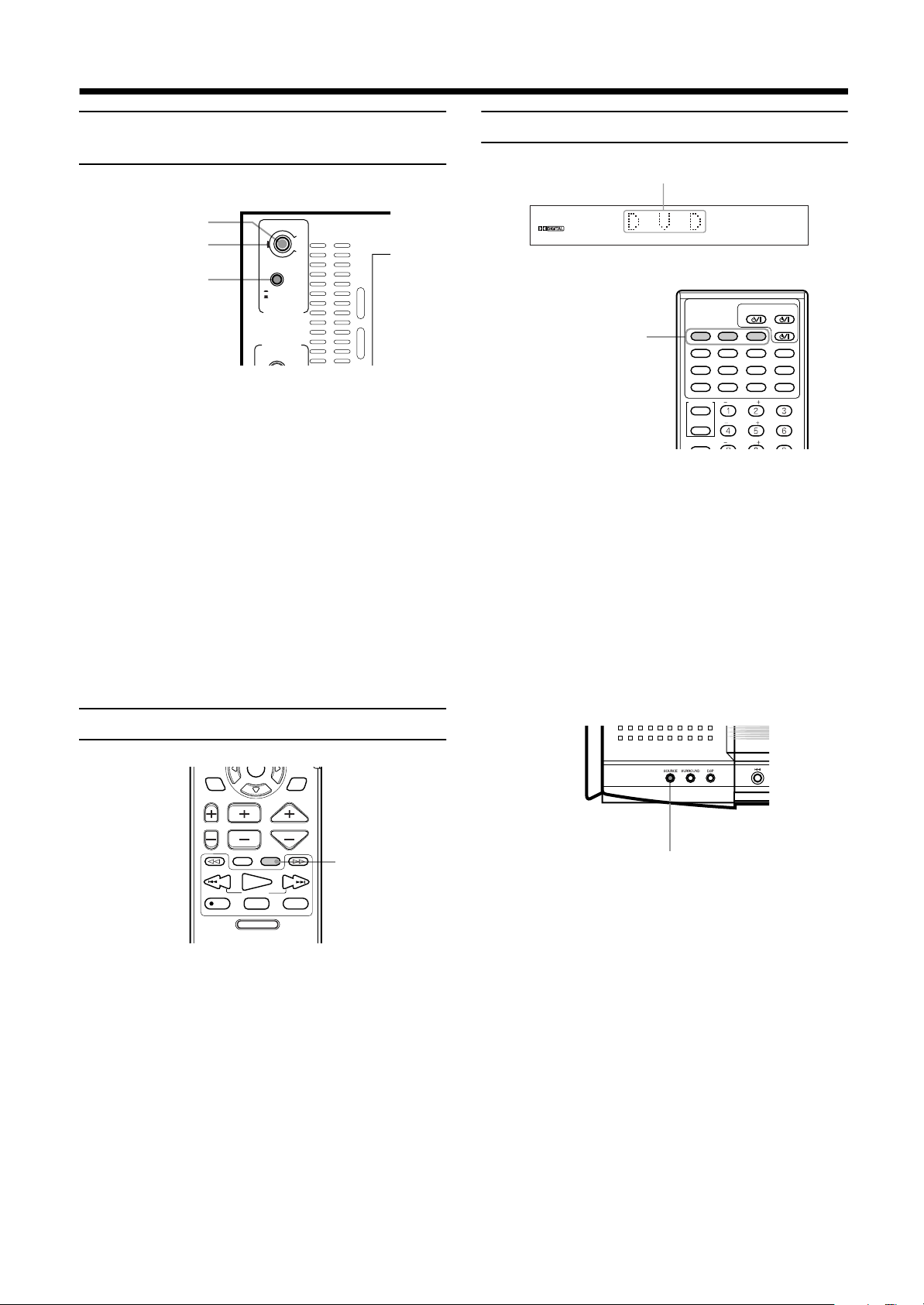
Muting the sound [MUTING]
Selecting the source to play
From the remote control:
Press one of the source selecting buttons.
DVD
FM/AM
AUX
Notes:
• When you press one o f the source selecting butt ons on the
remote control, the system automatically turns on.
• The cooling fan in the center unit turns on as long as the
DVD is selected as the playback source. It stops when other playback source (FM/AM or AUX) is selected.
On the center unit:
Select the DV D pla yer.
Select an FM or AM broadcast.
Each time you pres s the button, th e band alternates between FM and AM.
Select a component connected to the AUX
jacks.
From the remote control only:
Press MUTING to mute the sound through all speakers connected.
“MUTING” appears on the display window and volume turns off.
To restore the sound, press MUTING again so that “OFF” appears
on the display.
• Pressing VOLUME +/– also restores the sound.
18
THEATER
POSITION
CHANNELTV VOL VOLUME
TV/VIDEO
MUTING
/REW
PLAY
TUNING
REC
STOP
DVD MENU
F.SEARCHB.SEARCH
FF/
PAUSE
STROBEMEMORY
DSP
MODE
UPDOWN
MUTING
Press SOURCE until the source name you want appears on
the display.
The source changes as shown below each time the button is
pressed.
====
DVD
====
AM
====
FM
====
=
= (back to the beginning)
AUX
==
Note:
• When AM or FM is selected, the receiving frequency appears on the display w in dow. At the s am e t im e, th e AM or
FM indicator lights up on the display window.
Page 21
Basic operations
Changing the decode mode
[DECODE]
You can change the decode mode for digital audio pla yback.
From the remote control only:
STANDBY/ON
AUDIOTV/CATV/DBS
DECODE
TIME
CHOICEANGLERETURN
VCR
AUDIO
DISPLAY
SOUND
EFFECT
TEST
FM/AM
1
2
1
Press DVD to select DVD as the source.
2
Press DECODE to select the decode mode.
AUX DVD
SUBTITLE
TITLE
DIGEST
ZOOM
SUBWOOFER
CONTROL
VCR
CENTER
The display changes as shown b elow each time th e button i s
pressed.
====
AUTO/PCM
AUTO/PCM
====
=
= (back to the beginning)
DTS
==
Optimized for all discs playable on this system. (Default)
DTS
Select this mode when playing a DVD di sc
recorded in DTS Surround.
The DTS decoder will be selected as the internal decoder.
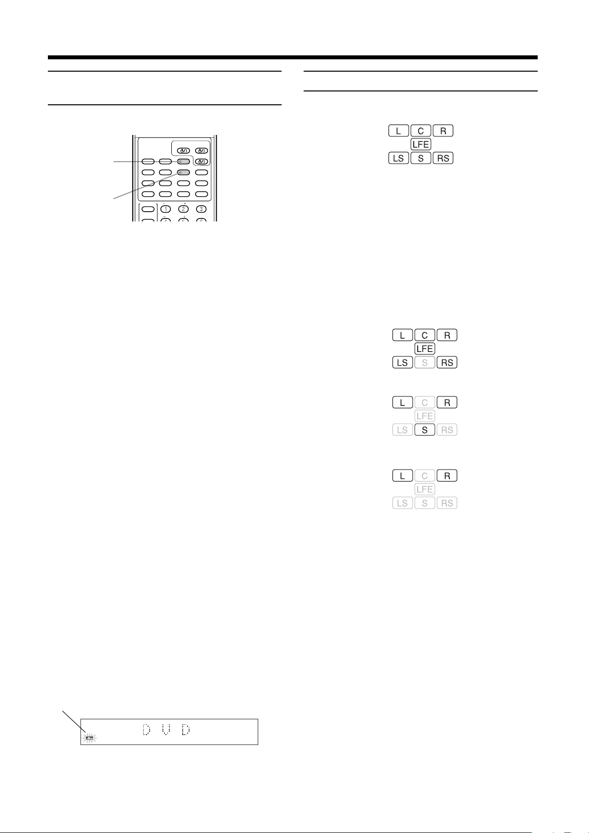
Audio channel display indicator
The audio channel indic ator shows the audio channe l configuration for the disc currently playing.
The indicators refer to the speaker channel as fol lows.
Left front speaker channel
L:
Right front speaker channel
R:
Center speaker channel
C:
Right surround speak er channel
RS:
Left surround speaker channel
LS:
Rear speaker channel (monaural)
S:
Sub-woofer channel
LFE:
The audio channel indicator i ndicates the type of disc currently
playing as follows.
With Dolby digital 5.1 ch or DTS digital 5.1 surround
When to try changing the decode mode
When the decode mode is set to the default AUTO/PCM setting
and a DVD recorded in Dolby Digital Surround or DTS Digital
Surround is played, the internal decoder will be automatically selected before audio playback begins. Depe nding on the disc recorded in DTS Digital Surround, this may result in a brief loss of
audio after playback starts. This is due to lost audio signals that
were inputted during internal decoder selection.
In these instances, lost audio can be prevented by manually selecting “DTS” beforehand.
However, please note that when the decode m ode is s et
to DTS, you will be unable to playb ack audio from discs
recorded in a mode othe r than the DTS Digital Surround.
After changing the dec ode mode and playing back a dis c, return
the decode mode to “AUTO/PCM”.
Note:
• Changing the playback s ourc e (e .g. AM /FM) w ill aut om atically return the decode mode to “AUTO/PCM”.
When a decode mode which differs from the type
of disc being played is selected
Insert a DVD disc in the center unit to display the type of audio being played in the D ecode mode indicator on the display window.
Audio cannot be play ed if a dec ode mode wh ich diffe rs from the
displayed mode is selected.
The selected decode mode flashes to indicate that the selected decode mode does not allow audio playback.
Example:
Flashes
When DTS is selected as the decode mode for Dolby
digital audio.
With Dolby digital (Lt/Rt*)
With stereo sound (e.g. Audio CD)
* Lt/Rt refers to the downmix output when connected
to a device that uses Dolby Pro Logic.
Note:
• The audio channel indicator does not show the actual
speaker channel that is producing sound.
EnglishEnglishEnglishEnglishEnglishEnglishEnglish
19
Page 22

Basic operations
DECODE
SUBTITLE
TITLE
AUDIO
Refrections from
behind
Early reflections
Direct sounds
Using the Sleep Timer [SLEEP]
EnglishEnglishEnglishEnglishEnglishEnglishEnglish
Using the Sleep Timer, you can fall asleep to music and know the
system will turn off by itself rather than play all night.
From the remote control:
TIME
DIGEST
ZOOM
SUBWOOFER
CONTROL
VCR
TV
SLEEP
SLEEP
SETTING
TV RETURN FM MODE
PLAY
MODE
Press SLEEP repeatedly.
The shut-off time changes as follows (in minutes):
====
====
====
====
10
OFF
20
(Canceled)
30
====
====
60
90
(back to the beginning)
When the shut-off time comes
The system turns off automatically.
To check or change the time remaining until
the shut-off time
Press SLEEP once.
The remaining time until the shut-off time appears in minutes.
• To change the shut-off time, press SLEEP repeatedly.
To cancel the Sleep Timer
Press SLEEP repeatedly until “SLEEP OFF” appears on the
display window.
• Turning off the power also cancels the S leep Timer.
CENTER
REAR-L
REAR-R
ENTER
====
CHOICEANGLERETURN
120
DISPLAY
SOUND
EFFECT
TEST
100+
AUDIO/
TV/VCR
CATV/DBS
====
150
====
Using the DSP Modes [DSP MODE]
The built-in Surround Processor provides two types of the DSP
(Digital Signal Processor) mode — Surround mode and DAP
(Digital Acoustic Processor) mode.
Surround modes
With this system, you can use two types of the Surround mode.
Dolby Surround (Dolby Digital and Dolby Pro Logic)*
Used to watch the soundtracks of software e ncoded with Dolby
Digital (bearing the mark ) or with Dolby Surround (bearing the mark ).
Dolby Digital and Dolby Pro Logic can be selected automatically
according to software played back.
DTS Digital Surround**
DTS Digital Surro und is a discre te 5.1 chann el digital audi o format
available on CD and DVD software.
To watch the soundtracks of video software bearing the mark ,
the system can provid e you with DTS Digital Surrou nd decoder.
DTS Digital Surround is automatically selec ted according to software played back.
Note:
• Change the decode mode from “AUTO /PCM” to “DTS” before playing an Audio CD recorded with DTS Digital Surround. For details, see page 19.
* Manufactured under license from Dolby Laborato-
ries. “Dolby”, “Pro Logic”, and the double-D symbol
are trademarks of Dolby Laboratories. Confidential
Unpublished Works. c1992-1998 Dolby Laboratories, Inc. All rights reserved.
** Manufactured under license from Digital Theater
Systems, Inc. US Pat. No. 5,451,942 and other
world-wide patents issues and pending. “DTS” and
“DTS Digital Surround” are trademarks of Digital
Theater Systems, Inc. c1996 Digital Theater Systems, Inc. All rights reserved.
DAP modes
The sound he ard in a c onc ert h all or club c on sists o f dire ct so und
and indirect sound — early reflections and reflections from behind. Direct sounds reach the listener directly without any reflection. On the other hand, indirect sounds are delayed by the
distances of the ceiling and walls. These direct sounds and indirect
sounds are the most important el ements of the acoustic surroun d
effects. The DAP mode can create these imp ortant element s, and
gives you a real “being there” feeling.
20
Page 23

Basic operations
THEATER:
LIVE CLUB:
Gives the feeling of a large theater.
Gives the feeling of a live m usic clu b wit h
a low ceiling.
DANCE CLUB:
HALL:
Gives a throbbing bass beat.
Gives clear vocal an d t he f eeli ng of a co ncert hall.
PAVILION:
Give the spacious feeling of a pavilion with
a high ceiling.
Notes:
• The DSP modes have no effect on monaural sources.
• The DOLBY DIGITAL indicator lights up when the signals
encoded with Dolby Digital come into the system.
• The PRO LOGIC indicator lights up when the signals encoded with Dolby Pro Logic decoder built in this system is
activated.
• The dts indicator lights up when the signals encoded with
DTS Digital Surround come into the system.
• The effects can be adjusted when the D AP mode is selected (see page 52).
To select the DSP mode
From the remote control:
SETTING
PLAY
MODE
THEATER
POSITION
TV RETURN FM MODE
ENTER
100+
AUDIO/
TV/VCR
CATV/DBS
DSP
MODE
DSP MODE
From the unit, SURROUND ON/OFF and DAP mode can be selected independently.
When playing a DVD disc with audio recorded in
Dolby surround, Dolby digital, or DTS digital surround audio:
Press SURROUND.
The current status (e.g. “SURROUND OFF”) appea rs on the display when the button is pressed, and changes between “SURROUND ON” and “SURROUND OFF” each time the button is
pressed subsequently.
• “PRO LOGIC”, rather than “SURROUND ON”, is displayed
when a source other than DVD is selected.
When selecting DAP:
Press DSP MODE.
The currently selected DAP mode appears on the display when the
button is pressed, and changes as foll ows each time the button is
pressed subsequently.
====
THEATER
====
PAVILION
====
LIVE CLUB
====
DSP OFF
====
DANCE CLUB
====
(back to the beginning)
====
HALL
Notes:
• The DSP mode indicator lights up when DAP mode is selected.
• The SURROUND indicator lights up when SURROUND
mode is selected.
CHANNELTV VOL VOLUME
TV/VIDEO
MUTING
F.SEARCHB.SEARCH
Press DSP MODE.
The currently selected DSP mode appears on the display when the
button is pressed, and chan ges as follo ws each time the but ton is
pressed subsequently.
====
SURROUND ON
DANCE CLUB
====
HALL
====
THEATER
====
PAVILION
====
LIVE CLUB
====
DSP OFF
====
====
(back to the beginning)
• “PRO LOGIC”, rather than “SURROUND ON”, is displayed
when a source other than DVD is selected.
• Select “SURROUND ON” when playing a video with audio
recorded in Dolby Pro Logic, Dolby digital, or DTS digital surround audio.
Selecting “OFF” loses any surround effect, and stereo playback
takes place.
Notes:
• It is possible to select only “SURROUND ON” and “SURROUND OFF” when playing a Dolby digital audio or DTS
digital audio DVD.
• The DSP mode indicator lights up when DSP mode other
than SURROUND is selected.
• The SURROUND indicator lights up when SURRO UND
mode is selected.
On the center unit:
EnglishEnglishEnglishEnglishEnglishEnglishEnglish
SURROUND
DSP MODE
21
Page 24

■■
Using the DVD player
and represent disc types.
EnglishEnglishEnglishEnglishEnglishEnglishEnglish
To turn on the system and TV
From the remote control:
2
STANDBY/ON
AUDIOTV/CATV/DBS
DVD
DECODE
TIME
CHOICEANGLERETURN
VCR
AUDIO
DISPLAY
SOUND
FM/AM
AUX
SUBTITLE
TITLE
DIGEST
ZOOM
1
Press AUDIO to turn power on.
• Pressing on the cent er unit also turns on power.
2
Press TV/CATV/DBS to turn TV on.
• On the TV, select the TV input source to VIDEO (e.g.
VIDEO 1).
• To turn on the other manufacturer’s TV with TV/CATV/
DBS , you need to change the transmittable signal
codes beforehand. See page 55.
1
3
Press OPEN/CLOSE to close the disc cover.
• When the current playback source is DVD, “CLOSE”
appears on the display window. On the TV, “CLOSE”
message appears on the openi ng on-screen.
• After the disc cover is closed, “READING” appears on the
display window. Then, the disc infor mation i s read and, if
the current playback source is DVD, the information is displayed as described in “Display when a disc is inserted” on
page 23. On the TV, while disc information is reading,
“NOW READING” message appears on the opening o nscreen.
4
Remove the disc after playback has finished.
Press OPEN/CLOSE to open the disc cover.
Then, remove the disc as shown below:
After that, press OPEN/CLOSE to close the disc cover.
CAUTION:
Do not put anything on the disc cover since it slides
back and forth, or opens. Doing so may resu lt in damage to the unit.
Notes:
• When you use Audio CDs, since no screen other than
opening screen i s displaye d, turni ng on the TV may not be
required.
• For detailed power on operation including the STANDBY
indicator illumination, see page 17.
To insert a disc
After turning on the system and the TV, insert a disc as follows:
On the center unit:
OPEN/CLOSE
1
Press OPEN/CLOSE to open the disc cover.
• When the current playback source is DVD, “OPEN”
appears on the display window. On the TV, “OPEN” message appears on the opening on-screen.
Notes:
• The system can pl ay back D VD, Audio CD , Video CD , CDR/CD-RW (audio-formatted) d iscs only. Do no t insert other
disc types.
For details about playable disc types, see page 5.
• When OPEN/CLOSE is pressed to close the disc cover,
playback automatically begins with some discs.
• You can insert a disc while playing other source (FM/AM
or AUX).
• When the disc cover is open, y ou can directly play the disc
by pressing DVD on the remote control or by selecting
“DVD” with SOURCE on the center unit.
• If the Region Code of the disc does not match your system, “REGION CODE ERROR!” appears on the opening
on-screen on the T V. This mean s that you canno t play the
disc.
• When OPEN/CLOSE is pressed in standby mode, the
center unit automa tically tu rns on and the disc c over slides
backwards and opens.
2
Place a disc.
Place a disc with label side up so th at it is securely seated.
22
Page 25

Using the DVD player
DVD MENU
TUNING
UPDOWN
REC
/REW
FF/
PAUSE
STROBEMEMORY
TV/VIDEO
MUTING
F.SEARCHB.SEARCH
PLAY
CHANNELTV VOL VOLUME
STOP
ENTER
THEATER
POSITION
DSP
MODE
DVD
AUDIOTV/CATV/DBS
STANDBY/ON
VCR
DECODE
SUBTITLE
TITLE
AUDIO
TIME
DIGEST
ZOOM
VCR
TV
SLEEP
CONTROL
SUBWOOFER
EFFECT
CENTER
TEST
REAR-L
DISPLAY
CHOICEANGLERETURN
SOUND
FM/AM
AUX
DVD
PLAY
STOP
7
3
Display when a disc is inserted
Opening on-screen:
NOW READING
When a DVD is inserted
Display window:
“READING”
“DVD”
====
Note:
• Playback begins immediately with some DVD discs.
When a Video CD is inserted:
Display window:
“READING”
(total number of tracks and total time disp lay)
“VCD 12 48:12”
====
+
“VCD 1 4:12”
After 4 seconds
To play a disc
From the remote control:
Press PLAY or DVD.
Playback begins from the first track.
On the center unit:
(first track time)
When an Audio CD is inserted
Display window:
“READING”
(total number of tracks and total time display)
“CD 12 48:12”
====
After 4 seconds
+
“CD 1 4:12”
(first track time)
Press 3333.
Playback begins from the first track.
To stop the disc
On the remote control: Press STOP.
On the center unit: Press 7.
Note:
• For DVD, or Video CDs recorded with PBC (playback control), pressing PLAY or 3 may display the m enu on the TV.
You may select items from the menu screen thus displayed and call up the locations to be viewed (see pages
25 and 26 for details).
On-screen guide icons
During DVD playback, you may see icons displayed over the picture. These have the following meanings.
Displayed at the beginning of a scen e recorded from
multiple angles (see page 33).
Displayed at the beginning of a scene recorded with
multiple audio la ng ua ge s (se e pag e32).
Displayed at the beginning of a scene recorded with
multiple subtitle languages (see page 31).
A setting is poss ible to su ppress display of these ic ons. The setting
is entered in the on-screen menu under “On-screen guide settings”
(see page 44 for details).
EnglishEnglishEnglishEnglishEnglishEnglishEnglish
About invalid operation icon
When you press a button, if t he uni t does not acc ept it s oper ati on,
appears on your television screen.
Operations are occasiona lly unacceptable even if is not displayed.
Note that some operations may not be accepted. For example,
some discs may not allow fast forward, fast backward or slow motion playback.
23
Page 26

Using the DVD player
ENTER
4, ¢
RM-STHA9J
DVD MENU
TUNING
UPDOWN
REC PAUSE
STROBEMEMORY
TV/VIDEO
MUTING
F.SEARCHB.SEARCH
PLAY
STOP
FF/
/REW
4
/REW, FF/
¢
4, ¢
Pausing
EnglishEnglishEnglishEnglishEnglishEnglishEnglish
From the remote control:
THEATER
POSITION
CHANNELTV VOL VOLUME
TV/VIDEO
/REW
PLAY
TUNING
REC
DVD MENU
Press PAUSE.
On the center unit:
8
Press 8888 .
Playback is paused.
When using a DVD or Video CD disc, pressing PAUSE or 8 while
paused moves to the next still picture.
STOP
MUTING
F.SEARCHB.SEARCH
FF/
PAUSE
STROBEMEMORY
DSP
MODE
UPDOWN
PAUSE
On the center unit:
Continuously press ¢¢¢¢ or 4444.
Continuously pressing the button increases the fast forward or
backward speed as follows:
5× = 20×
To return to the normal speed
Release ¢ or 4.
Locating the beginning
Locates the beginning of the title or
chapter with DVDs.
Locates the beginn ing of the track with Audio CDs and Video
CDs.
❏For DVD: During playback
For Audio CD: During playback or wh e n st opped
For Video CD: During playback or when stoppe d
From the remote control:
To resume playback
From remote control: Press PLAY.
On the center unit: Press 3.
Fast forward and backward
❏During playbac k
From the remote control:
Press ¡¡¡¡ or 1111.
Each time you press the button, the fast forward or backward speed
changes as follows:
2× = 5× = 10× = 20× = 60×
To return to the normal speed
Press PLAY.
ENTER
THEATER
POSITION
CHANNELTV VOL VOLUME
TV/VIDEO
/REW
PLAY
TUNING
REC
STOP
DVD MENU
DSP
MODE
MUTING
F.SEARCHB.SEARCH
FF/
UPDOWN
PAUSE
STROBEMEMORY
1
or
Press FF/¢¢¢¢ or 4444/REW.
On the center unit:
¡
Press ¢¢¢¢ or 4444.
Press 4 to locate the beginning of the current chapter, title, or
track. Press 4 twice quickly to locate the beginning of the previous one.
Press ¢ to locate the beginn ing of the next ch apter, title, or trac k.
Note:
• When you play a Video CD with PBC function or a DVD
disc, the center unit may locate different place, but it will
generally locate the beginning of the title or chapter or
track.
24
Page 27

Using the DVD player
TUNING
UPDOWN
REC
/REW
FF/
PAUSE
STROBEMEMORY
TV/VIDEO
MUTING
F.SEARCHB.SEARCH
PLAY
CHANNELTV VOL VOLUME
STOP
AUDIO/
TV/VCR
CATV/DBS
ENTER
PLAY
MODE
THEATER
POSITION
DSP
MODE
DVD MENU
DVD
AUDIOTV/CATV/DBS
STANDBY/ON
VCR
DECODE
SUBTITLE
AUDIO
TIME
DIGEST
ZOOM
VCR
TV
CONTROL
SUBWOOFER
EFFECT
CENTER
TEST
REAR-L
DISPLAY
CHOICEANGLERETURN
SOUND
FM/AM
AUX
TITLE
1
2
1
Resuming playback
The center unit stores the position on a disc where you want to interrupt playback at, and resumes playback from that position later.
To let work the resuming playback, the item RESUM E in the SYSTEM menu must be set to ON beforehand. Otherwise, set it to
OFF. See page 45.
To store the playback position
During playback, press STOP or AUDIO on the remote
control.
Or
During playback, press 7777 or on the center unit.
The center unit stores the positio n a t which STOP or 7 is pressed,
and the RESUME indicator on the display window is lit. The last
stored memory overrides the previous memory.
Note:
• The interrupted position is stored even when AUDIO
on the remote control, or on the center unit, is
pressed to switch power OFF (standby).
To resume playback from the stored position
While stopped, press PLAY on the remote control or press
3333 on the center unit.
Playback begins from the stored position.
• When the center unit is in standby mode, you can activate
resuming playback by pressing PLAY on the remote control.
• Changing the source during playback also stores the interrupted
position. To resume playback from the stored position, press
PLAY or DVD on the remote control. Selecting “DVD” by
pressing SOURCE or press ing 3 on the center unit will also
resume playback.
Selecting playback from the DVD
menu
DVD discs generally have their own m enus which show the disc
contents. These menu s contain various items such as titles of a
movie, names or songs, or artist information, and display them on
the TV.
You can locate a desired scene by using the menu.
❏During playback
From the remote control only:
1
Press DVD MENU or TITLE.
The menu appears on the TV screen.
Example
Notes:
• When you perform the resuming operati on for a Video CD
with the PBC function, the center unit may resume playback from a point sl ightly earlie r than the resume p oint you
stored.
• Resuming playback does not work for Audio CDs.
• Resuming playback does not work for program play and
random play.
To clear the stored position
To clear the stored position, perform one of the following operations:
The RESUME indicator on the display window will go out.
• Open the disc cover.
• While stopped, pr ess STOP on the remot e control or 7 on the
center unit once again .
• In standby mode, press AUDIO on the remote control o r
on the center unit once again to turn on the system.
2
Press the
2222/3333/5555/∞∞∞∞
cursors to select a
desired item, then press ENTER.
The center unit starts playback of t he sel ected item.
• With some discs, you can also select items by entering the
corresponding number using the number buttons, which
may cause the unit to automatically start playback.
About menu
Normally, a DVD disc which contains more th an one title may
have a “title” menu whic h lists th e titles. In th is case, the me nu ap pears on the TV by pressing TITLE. Some DVD discs may also
have a different menu which appears by pressing DVD MENU.
See the instructions of each DVD disc for its particular menu.
Notes:
• When appears on the TV by pressing TI TLE in step
1:
The disc does not have a menu listing the titles.
•
When appears on the TV by pressing DVD MENU in
step 1:
The disc does not have a menu.
25
EnglishEnglishEnglishEnglishEnglishEnglishEnglish
Page 28

Using the DVD player
1
Selecting the location to view from
EnglishEnglishEnglishEnglishEnglishEnglishEnglish
the Video CD menu
When playing back Video CDs recorded with PBC (playback control), a list of t he recorded contents may app ear on the TV as a
menu. The location to view may be conveniently called up from
this menu screen.
❏When the menu appears on the T V during playback with PBC.
From the remote control only:
TIME
DIGEST
ZOOM
RETURN
1
Use the number buttons (1~10, +10) to select
CONTROL
VCR
TV
SLEEP
SETTING
ANGLERETURN
SUBWOOFER
TV RETURN FM MODE
the desired number of the item.
To select 3 on menu : Press 3.
To select 11 on menu : Press +10 = 1.
Playback starts from the selected item.
Example
Press RETURN to return to the menu screen.
When “NEXT” or “PREVIOUS” appears on the TV, the center unit generally works as follows:
• Pressing ¢ turns to the next page.
• Pressing 4 returns to the previous page.
The method of the operation is different depending on the
disc.
Activating the PBC function
To activate the PBC function when a PBC-compatible Video
CD is being played back without the PBC function, press
STOP then press PLAY.
When the PBC function is activated, “PBC” appears on the
display window.
You can also activate the PBC fun ction using the on-screen
display as follows:
1. Press PLAY MODE.
2. Press the 2222/3333 cursors to move the pointer to [PBC CALL],
then press ENTER.
During Video CD playbac k
CENTER
REAR-L
REAR-R
CHOICE
DISPLAY
SOUND
EFFECT
TEST
100+
1
To specify the title, chapter, or
track number for playback
Use the number buttons to specify the title (DVDs) or track number (CDs) to begin playback from the desired location.
❏For DVD: While stopped (for title playback)
During playing back a screen other than the
menu screen (for chapter playback)
For Audio CD: During playback or while stopped
For Video CD: During playback without PBC function or
while stopped
From the remote control only:
CHOICEANGLERETURN
CENTER
REAR-L
REAR-R
SOUND
EFFECT
TEST
100+
SUBWOOFER
CONTROL
VCR
TV
SLEEP
SETTING
TV RETURN FM MODE
1
Press the number buttons (1~10, +10) to select
the desired title, chapter, or track number.
Selecting numbers
Selecting 1~10:
Press the relevant button between 1 and 10.
Selecting 11 or higher:
To select 13: Press +10 = 3 .
To select 24: Press +10 = +10 = 4.
To select 40: Press +10 = +10 = +10 = 10.
The specified title, chapter, or t rack number a ppears on th e display
window, and playback begins from that location.
• You can also see the selected title, chapter, or track number on
the on-screen display.
Notes:
• When appears on the TV.
The title, chapter, or track you have selected is not contained in the disc.
• This function does not work during Video CD playback
with PBC function.
VCD CONTROL
REPEAT A-B REPEAT TIME SEARCH PBC CALL
Cancelling the PBC function
If you want to play back a PBC-compatible Video CD without
activating the PBC function, start playback by using the number buttons instead of the PLAY button.
26
Page 29

To play from the beginning of a ti-
GO TO CHAPTER =
DVD CONTROL
REPEAT A-B REPEAT TIME SEARCH CHAP. SEARCH
tle, chapter, or track
The beginning of previous or la ter titles, chapters, or tracks may be
skipped.
❏For DVD: During playback
For Audio CD: During playback or while stopped
For Video CD: During playback without PBC function or
while stopped
From the remote control only:
CHANNELTV VOL VOLUME
TV/VIDEO
MUTING
F.SEARCHB.SEARCH
PLAY
TUNING
STOP
DVD MENU
FF/
UPDOWN
STROBEMEMORY
/REW
REC PAUSE
1
1
Press ¢
¢ or 4
¢¢
• Press ¢ the required number of times to move to a later
title, chapter, or track.
• Press 4 the required number of times to return to the
previous title, chapter, or track.
• Press 4 once to return to the beginning of th e title , chapter, or track currently playing.
4.
44
Using the DVD player
2
Press the 2222/3333 cursors to move the pointer to
[CHAP. SEARCH], then press ENTER.
“GO TO CHAPTER = ” appears under the menu.
3
Press the number buttons (0 ~ 9) to enter the
desired chapter number.
The selected chapter number appears in the message area.
Example:
To select chapter number 8: Press 8.
To select chapter number 37: Press 3 = 7.
4
Press ENTER.
The center unit starts playback from the selected chapter.
To return to the regular display
Press PLAY MODE again.
Notes:
• When the chapter number is incorrect in step 3:
Overwrite the incorrect number with the correct number.
• When is displayed in the TV screen in step 4:
The chapter you hav e selected is not cont ained in the disc,
or chapter search does not work on the disc.
• With some discs, the center unit automatically starts
searching for the chapter after entering the chapter number in step 3.
Notes:
• Press ¢ or 4 on the center unit for the same operation.
• This function may not work with some DVD discs.
• This function does not work during Video CD playback
with PBC function.
To specify the chapter number for
playback [CHAP. SEARCH]
If the current title of a DVD disc being played is divided into cha pters, you can skip to a desired chapter by specify ing the chapter
number using the on-screen display.
❏During playback
From the remote control only:
SUBWOOFER
CENTER
REAR-L
REAR-R
ENTER
EFFECT
TEST
100+
AUDIO/
TV/VCR
CATV/DBS
DSP
MODE
3
2, 4
1
CONTROL
VCR
TV
SLEEP
SETTING
PLAY
MODE
THEATER
POSITION
TV RETURN FM MODE
EnglishEnglishEnglishEnglishEnglishEnglishEnglish
1
Press PLAY MODE.
The on-scr ee n di sp l a y a ppears on the TV.
27
Page 30

Using the DVD player
To specify the time for playback
EnglishEnglishEnglishEnglishEnglishEnglishEnglish
[TIME SEARCH]
You can play a disc from the desired position by specifying the
elapsed time from the beginning of the disc use the TIME
SEARCH function.
Note that some DVD discs do not contain time information , and
the TIME SEARCH function cannot be used.
❏For DVD: During playback
For Audio CD: During playback
For Video CD: During playback without PBC function
From the remote control only:
1
CONTROL
VCR
TV
SLEEP
SETTING
PLAY
MODE
THEATER
POSITION
SUBWOOFER
CENTER
REAR-L
REAR-R
TV RETURN FM MODE
ENTER
EFFECT
TEST
100+
AUDIO/
TV/VCR
CATV/DBS
DSP
MODE
3
2, 4
3
Use the number buttons (0~9) to enter the
time.
The specified time appears in the message area.
Example (for DVD):
To playback from 2(H):34(M):00(S)
You do not have to press “0 ” to
enter the trailing zeros (for the
last two digits in the example).
Of course, it is possible to enter
them.
• You can specify the time in
hour/minute/second format
for DVD discs, and in
minute/second format for
Audio and Video CDs.
When you make a mistake:
Press the 2 cursor to move the cursor to an incorrect number
and enter the correct number.
4
Press ENTER.
The center unit starts playback from the selected time.
Press “2”
Press “3”
Press “4”
Press ENTER
1
Press PLAY MODE.
The on-screen display appears on the TV.
2
Press the 2222/3333 cursors to move the pointer to
[TIME SEARCH], then press ENTER.
“GO TO” appears under the menu.
(for DVD)
DVD CONTROL
REPEAT A-B REPEAT TIME SEARCH CHAP. SEARCH
GO TO 2 : 3 4 : 0 0
(for Audio CD)
CD CONTROL
REPEAT A-B REPEAT TIME SEARCH
GO TO 0 2 : 3 4
(for Video CD)
VCD CONTROL
REPEAT A-B REPEAT TIME SEARCH PBC CALL
Selected time
Selected time
To return to the regular display
Press PLAY MODE again.
Notes:
• When appears on the TV in step 2:
The time you have selected is not contained on the disc,
or the TIME SEARCH function does not work on the disc.
• During program play or random play, the TIME SEARCH
function does not work.
28
GO TO 0 2 : 3 4
Selected time
Page 31

To select the screen for playback
DVD
FM/AM
AUX
When the selected title,
chapter, or track is in
the lower right-hand
corner for the screen,
press the 3 cursor.
DVD MENU
TUNING
UPDOWN
REC
/REW
FF/
PAUSE
STROBEMEMORY
TV/VIDEO
MUTING
F.SEARCHB.SEARCH
PLAY
CHANNELTV VOL VOLUME
STOP
THEATER
POSITION
DSP
MODE
1,2
from the digest screen [DIGEST]
The center unit can display th e openin g scene of eac h title or cha pter on a DVD or each track of a Video CD.
You can select a desired title, chapter or track from the opening
scenes displayed on the TV.
❏For DVD: While stopped or during playback
For Video CD: While stopped or during playback without
PBC function.
From the remote control only:
DECODE
SUBTITLE
/REW
1
Press DIGEST.
1
TITLE
DIGEST
SUBWOOFER
CONTROL
VCR
CENTER
TV
REAR-L
SLEEP
REAR-R
SETTING
TV RETURN FM MODE
PLAY
MODE
THEATER
POSITION
CHANNELTV VOL VOLUME
TV/VIDEO
/REW
PLAY
TUNING
REC PAUSE
DVD MENU
ENTER
STOP
TIMEZOOM
CHOICEANGLERETURN
MUTING
AUDIO
DISPLAY
SOUND
EFFECT
TEST
100+
AUDIO/
TV/VCR
CATV/DBS
DSP
MODE
F.SEARCHB.SEARCH
FF/
UPDOWN
STROBEMEMORY
2,3
FF/
¢4
Using the DVD player
2
Press the 2222/3333/5555/∞∞∞∞ cursors to select the
desired title, chapter, or track.
When the disc contains m ore th an 9 t itle s, ch ap ters, o r tra cks,
the digest screen will have more than one page.
In this case, display a different page of the digest with the
method described below.
To display the next page: Press
To display the previous page: Press
¢¢¢¢
.
4444
.
Or
When the selected title, chapter or track is in the upper lefthand corner of the screen, press the 2 cursor.
3
Press ENTER.
The center unit starts playback from the selected title, chapter
or track.
To return to the regular display before pressing
ENTER in step 3:
Press DIGEST again.
Note:
• With some discs, depending on the contents, it may take
some time until all the scenes appear on the screen.
To advance the picture one frame
at a time
• DVD is stopped
Up to nine first scenes of
each title may be displayed.
• DVD is playing
Up to nine first scenes of
each chapter in the current title may be displayed.
• Video CD
Up to nine first scenes of
each track may be displayed.
Advancing a paused still picture one frame at a time.
❏During playback
From the remote control:
1
Press PAUSE at the location at which the
picture is to be advanced.
The picture is paused.
2
Press PAUSE again.
Each time you press PAUSE, th e still picture advances to the
next frame.
Press PLAY to return to normal playback.
Note:
• You can perform th e above ope ration usi ng 8 button on
the center unit.
29
EnglishEnglishEnglishEnglishEnglishEnglishEnglish
Page 32

Using the DVD player
DVD MENU
TUNING
UPDOWN
REC
STROBEMEMORY
TV/VIDEO
MUTING
F.SEARCHB.SEARCH
PLAY
CHANNELTV VOL VOLUME
STOP
FF/
/REW
PAUSE
1
Slow-Motion Playback [SLOW]
EnglishEnglishEnglishEnglishEnglishEnglishEnglish
❏During playbac k
From the remote control only:
CHANNELTV VOL VOLUME
2
TV/VIDEO
MUTING
F.SEARCHB.SEARCH
PLAY
TUNING
STOP
DVD MENU
FF/
PAUSE
STROBEMEMORY
UPDOWN
1
/REW
REC
1
Press PAUSE at the section you wish to view
in slow motion.
The image will pause.
2
Press ¡¡¡¡ or 1
Pressing ¡ will playback your selection in slow motion,
starting from the paused frame.
Pressing 1 will playback your selection in reverse slow m otion (DVD only).
Each time you press either button during slow-motion, the
playback speed will increase as follows:
Forward:
Reverse:
Pausing slow-motion playback
Press PAUSE to pause slow-motion playback.
Restoring regular playback
Press PLAY to resume normal playback.
Notes:
• Audio is automatically muted during slow-motion playback.
• Video CDs cannot be played in reverse slow-motion.
1.
11
1/32 = 1/16 = 1/8 = 1/4 = 1/3 = 1/2
1/16 = 1/12 = 1/8 = 1/4 = 1/3
To display Continuous Photos
[STROBE]
Nine still pictures may be displayed one after th e other.
❏During playback
From the remote control:
1
Press PAUSE continuously to display continuous photos.
When the screen appears displaying the nine pictures, release
PAUSE.
The screen plays back the nine pictures in strobe-like action.
• Press PAUSE during strobe playback to pause.
• Press PAUSE to display the next nine still pictures.
• Press PLAY to resume strobe playback.
To clear the s trobe sc reen,
the normal screen appears.
Notes:
• Audio is not played during strobe playback.
• You can perform the above operation using
the center unit.
press PAUSE continuously until
button on
8
30
Page 33

Using the DVD player
DVD
DECODE
TITLE
AUDIO
TIME
DIGEST
VCR
TV
SLEEP
SETTING
TV RETURN FM MODE
100+
AUDIO/
TV/VCR
CATV/DBS
CONTROL
SUBWOOFER
EFFECT
CENTER
TEST
REAR-R
ENTER
PLAY
MODE
THEATER
POSITION
DSP
MODE
REAR-L
DISPLAY
CHOICEANGLERETURN
SOUND
FM/AM
AUX
SUBTITLE
ZOOM
1
2,3
Zooming a scene [ZOOM]
❏During playback or while pa us e d .
From the remote control only:
TITLE
ZOOM
CONTROL
VCR
TV
SLEEP
SETTING
PLAY
MODE
THEATER
POSITION
1
Press ZOOM.
1
2
“ZOOM” appears on the TV.
The unit zooms in to the center part of the scene to produce a
double-sized image.
DECODE
SUBTITLE
TIME
DIGEST
CHOICEANGLERETURN
SUBWOOFER
CENTER
REAR-L
REAR-R
TV RETURN FM MODE
ENTER
AUDIO
DISPLAY
SOUND
EFFECT
TEST
100+
AUDIO/
TV/VCR
CATV/DBS
DSP
MODE
Changing the Subtitle Language
[SUBTITLE]
Some DVD discs contain subtitles. With such discs, you can
choose which kind of subtitles to display (or turn off subtitles entirely). At the beginning of sub titled pa rts, appears on the TV.
❏During playback
From the remote control only:
1
Press SUBTITLE.
The on-screen display appears on t he T V .
ZOOM
2
Press the 2222/3333/5555/∞∞∞∞ cursors to move the
zoomed-in scene.
To pause zoom play
Press PAUSE.
To resume zoom play, press PLAY.
To return to normal playback
Press ZOOM again.
Note:
• During Zoom play, the picture may be garbled or noisy.
2
Press the 2222/3333 cursors to select the desired
subtitle.
Each time you press the 2/3 cursors, the subtitle changes.
Example:
ENGLISH
1/3 ENGLISH
2/3 FRENCH
3/3 SPANISH
–/3 (off)
3
Press ENTER.
1 / 3ON
The Subtitle selection display disappears on the TV.
Turning subtitles ON/OFF
Press SUBTI TLE.
Pressing SUBTITLE toggles subtitle display ON and OFF.
Notes:
• When appears on the TV:
You cannot select the subtitle.
• The selected language may abbreviated on the TV. See
“Appendix A: Table of languages and their abbreviations”
in this manual.
• The Subtitle selection display will automatically disappear
if you do not change the subtitle for 10 seconds.
31
EnglishEnglishEnglishEnglishEnglishEnglishEnglish
Page 34

Using the DVD player
DVD
VCR
DECODE
TITLE
TIME
DIGEST
VCR
TV
SLEEP
SETTING
TV RETURN FM MODE
100+
AUDIO/
TV/VCR
CATV/DBS
CONTROL
SUBWOOFER
EFFECT
CENTER
TEST
REAR-R
ENTER
PLAY
MODE
THEATER
POSITION
DSP
MODE
REAR-L
DISPLAY
CHOICEANGLERETURN
SOUND
FM/AM
AUX
SUBTITLE
ZOOM
AUDIO
1
2,3
Changing the audio language or
EnglishEnglishEnglishEnglishEnglishEnglishEnglish
sound [AUDIO]
Some DVD discs contain multiple audio tracks. With such discs,
you can choose which audio track to listen to during playback.
At the beginning of “multi-audio language” parts, appears on
the TV.
❏During playbac k
From the remote control only:
FM/AM
AUX
TITLE
SUBTITLE
DIGEST
ZOOM
SUBWOOFER
CONTROL
VCR
CENTER
TV
SLEEP
SETTING
TV RETURN FM MODE
PLAY
MODE
THEATER
POSITION
1
Press AUDIO.
The on-screen display appears on the TV.
REAR-L
REAR-R
ENTER
DVD
DECODE
TIME
CHOICEANGLERETURN
VCR
AUDIO
DISPLAY
SOUND
EFFECT
TEST
100+
AUDIO/
TV/VCR
CATV/DBS
DSP
MODE
1
2,3
Changing the audio channel [AUDIO]
For in some karaoke Video CDs, on e of the audio channels includes a vocal while the other does not.
With such disc s, you can choose to enjoy karaoke without the vocal or with the vocal by selecting the audio channel to be played
back.
❏During playback
From the remote control only:
1
Press AUDIO.
The on-screen display appears on the TV.
2
Press AUDIO or the 2222/3333 cursors to select
the desired audio language or sound.
Each time you pre ss the but ton, the audi o lang uage o r sound
changes.
Example:
1 / 3 ENGLISH
3
Press ENTER.
The Audio selectio n display disappears on th e TV.
Notes:
• When appears on the TV:
You cannot select the audio.
• The selected language may abbreviated on the TV. See
“Appendix A: Table of languages and their abbreviations”
in this manual.
• The Audio selection display will automatically disappear if
you do not change the subtitle for 10 seconds.
2
Select the audio channel(s) to be played
back using AUDIO or the 2222/3333 cursors.
Each time you press the but ton, the audio channel changes.
Example:
STEREO
L
R
STEREO:
You hear normal stereo playb ack.
You hear the L (Left) channel sig nal played
L:
back from both the left and right speakers.
You hear the R (Right) channel signal pl ayed
R:
back from both the left and right speakers.
3
Press ENTER.
The Audio selection dis p la y dis a pp e ar s on the TV.
Notes:
• When appears on the TV:
You cannot select the audio.
• The Audio selection display will automatically disappear if
you do not change the subtitle for 10 seconds.
STEREO
32
Page 35

Using the DVD player
DECODE
TITLE
AUDIO
SUBTITLE
TIME
DIGEST
VCR
TV
SLEEP
SETTING
TV RETURN FM MODE
100+
AUDIO/
TV/VCR
CATV/DBS
CONTROL
SUBWOOFER
EFFECT
CENTER
TEST
REAR-R
ENTER
PLAY
MODE
THEATER
POSITION
DSP
MODE
REAR-L
DISPLAY
CHOICERETURN
SOUND
ZOOM
ANGLE
1
2,3
The selected camera angle
Viewing from Multiple Angles [ANGLE]
You can enjoy a variety of sc ene an gles if th e DVD di sc contain s
“multi-angle” parts, where multiple cameras were used to shoot
the same scene from different angl es . You ca n sele ct one of thes e
viewing angles from the normal screen or on-screen display.
At the beginning of “multi-angle” parts, appears on the TV.
Using the ANGLE button
❏During playback
From the remote control only:
TIME
2,3
1
ZOOM
CONTROL
VCR
TV
SLEEP
SETTING
PLAY
MODE
THEATER
POSITION
DIGEST
ANGLE
SUBWOOFER
TV RETURN FM MODE
CENTER
REAR-L
REAR-R
ENTER
DISPLAY
CHOICERETURN
SOUND
EFFECT
TEST
100+
AUDIO/
TV/VCR
CATV/DBS
DSP
MODE
Selecting an angle from the angle list display
❏During playback
From the remote control only:
1
Hold down ANGLE for more than 1 second.
Up to nine camera angles recorded on a disc appear on the TV.
1
Press ANGLE.
The on-scr ee n di sp l a y a ppears on the TV.
2
Press ANGLE or the 2222/3333 cursors to select
the desired angle.
Each time you press the bu tton, the angle changes.
Example:
1 / 3
2 / 3
3 / 3
3
Press ENTER.
The Angle selection display disappears on the TV.
Note:
• When appears on the TV:
The current scene is not recorded from multiple angles.
• The Angle selection display will automatically disappear if
you do not change the subtitle for 10 seconds.
1 / 3
2
Press the 2222/3333/5555/∞∞∞∞ cursors to select the
desired angle.
3
Press ENTER.
The selected angle appears on the TV.
Note:
• When appears on the TV:
The current scene is not recorded from multiple angles.
• During the operation above, audio is muted.
EnglishEnglishEnglishEnglishEnglishEnglishEnglish
33
Page 36

Using the DVD player
THEATER 1
THEATER 2
THEATER 3
THEATER OFF
SETTING
TV RETURN FM MODE
100+
AUDIO/
TV/VCR
CATV/DBS
ENTER
THEATER
POSITION
DSP
MODE
PLAY
MODE
2
1
REPEAT TITLE
DVD CONTROL
REPEAT A-B REPEAT TIME SEARCH CHAP. SEARCH
REPEAT TITLE (current title repeat)
REPEAT CHAPTER (current chapter repeat)
No indication (off)
The selected re pea t
mode appears on the
TV.
REPEAT ALL
CD CONTROL
REPEAT A-B REPEAT TIME SEARCH
Selected repea t mode
REPEAT ALL
VCD CONTROL
REPEAT A-B REPEAT TIME SEARCH PBC CALL
Selected repeat mode
Selecting the Picture Character
EnglishEnglishEnglishEnglishEnglishEnglishEnglish
[THEATER POSITION]
You can select the quality of the image from among four options
(OFF, 1, 2, and 3) according to the type of programming, picture
tone or personal preferences.
❏During playbac k
From the remote control only:
1
1
Press THEATER POSITION to select the
desired picture character.
Each time you press the button, the picture character changes
as follows:
SETTING
PLAY
MODE
THEATER
POSITION
TV RETURN FM MODE
ENTER
THEATER 1
100+
AUDIO/
TV/VCR
CATV/DBS
DSP
MODE
Repeating a current title, chapter
or track, or all tracks [REPEAT]
❏For DVD: During playback
For Audio CD: During playback or while stopped
For Video CD: During pla yback without PBC function or
while stopped
From the remote control only:
1
Press PLAY MODE.
The on-screen display appears on the TV.
2
Press the 2222/3333 cursors to move the pointer to
[REPEAT], then press ENTER.
Each time you press ENTER, the repeat mode changes as follows:
For DVD
“THEATER OFF” is the normal position.
Selecting a high er number res ults in a d arker pict ure ch aracter.
To turn off the on-screen display
Press ENTER.
• The THEATER POSITION screen will automatically close if
left idle for more than 5 seconds.
34
Selected picture character
The current title or chapter will be repeated.
For Audio CD and Video CD
(for Audio CD)
(for Video CD)
REPEAT ALL (all track repeat)
REPEAT 1 (current track repeat)
No indication
(off)
The current track or all tracks is/are played repeatedly.
Page 37

Using the DVD player
CD CONTROL
REPEAT A-B REPEAT TIME SEARCH
A 0:0:16 B 0:1:31
Point A Point B
VCD CONTROL
REPEAT A-B REPEAT TIME SEARCH PBC CALL
A 0:0:16 B 0:1:31
Point A Point B
To stop repeat playback
Press STOP.
• When a DVD disc is set, the center unit stops p layback and
quits repeat m ode.
• When an Audio or Vid eo CD is set , the center u nit stops pl ayback but remains in repeat mode.
To quit repeat playback without stopping playback
Move the pointer to [REPEAT] and press ENTER re peatedl y until
the [REPEAT] display turns off.
Tu turn off the on-screen display
Press PLAY MODE.
Notes:
• If appears when pressing ENTER in step 2 during
DVD playback.
You cannot repeat the title or chapter because of the disc
contents.
• With some DVD discs, repeat function does not work.
• Repeat play function cannot be used during Video CD
playback with PBC function.
Repeating a desired part [A-B REPEAT]
❏During playback
From the remote control only:
1
1
Press PLAY MODE.
The on-scr ee n di sp l a y a ppears on the TV.
2
Press the 2222/3333 cursors to move the pointer to
[A-B REPEAT], then press ENTER at the
beginning of the part you want to repeat
(point A).
SETTING
TV RETURN FM MODE
PLAY
MODE
THEATER
POSITION
ENTER
100+
AUDIO/
TV/VCR
CATV/DBS
DSP
MODE
2,3
(for Audio CD)
(for Video CD)
To quit A-B repeat playback
Press STOP. The center un it stops pl ayback and quits A-B repeat
mode.
Quitting A-B repeat mode without stopping playback
Move the pointer to [A-B REPEAT] and press ENTER.
Pressing the 4 or ¢ will also quit A-B repeat mode.
To turn off the on-screen display
Press PLAY MODE.
Notes:
• If appears when pressing ENTER in step 2 during
DVD playback.
You cannot repeat the selected portion because of the
disc conten ts.
• The A-B REPEAT function cannot be us ed during program
or random playback.
• With DVD discs, A-B repeat playbac k is possible only with in a single title.
3
Press ENTER at the end of the part you want
to repeat (point B).
The unit locates “A” and starts repeat playback between “A”
and “B”.
(for DVD)
DVD CONTROL
REPEAT A-B REPEAT TIME SEARCH CHAP. SEARCH
A 0:00:16 B 0:01:16
Point A Point B
EnglishEnglishEnglishEnglishEnglishEnglishEnglish
35
Page 38

Using the DVD player
REPEAT PROGRAM RANDOM
Programming the Playing Order
EnglishEnglishEnglishEnglishEnglishEnglishEnglish
[PROGRAM]
You can play titles or tra cks on a disc in the desired o rder using th e
Program funct ion.
❏While stopped
From the remote control only:
SUBWOOFER
CENTER
REAR-L
REAR-R
ENTER
PLAY
TUNING
STOP
3
9
15
3
9
15
MUTING
4
10
16
4
10
16
EFFECT
TEST
100+
AUDIO/
TV/VCR
CATV/DBS
DSP
MODE
F.SEARCHB.SEARCH
FF/
UPDOWN
PAUSE
STROBEMEMORY
5
11
17
5
11
17
6
12
18
6
12
18
CONTROL
VCR
TV
SLEEP
SETTING
TV RETURN FM MODE
PLAY
1
1
Press PLAY MODE.
MODE
THEATER
POSITION
CHANNELTV VOL VOLUME
TV/VIDEO
/REW
REC
The on-screen display appears on the TV.
2
Press the 2222/3333 cursors to move the pointer to
[PROGRAM] and press ENTER.
REPEAT PROGRAM RANDOM
2
1
3
8
7
14
13
The program table appears under the menu bar (as shown
above).
The PROGRAM indicator appears on the display window.
3
Select the titles or tracks in the desired order
using the number buttons (1~10, +10).
Up to 18 titles or tracks can be progra mmed . You may sel ec t
the same titles or track more than once.
2
1
3
8
7
14
13
3
2
4
Selecting numbers
Selecting 1~10:
Press the relevant button between 1 and 10.
Selecting 11 or higher:
To select 13: Press +10 = 3 .
To select 24: Press +10 = +10 = 4.
To select 40: Press +10 = + 10 = +10 = 10.
If you mistakenly select the wrong t itle o r t rack n umb er pr ess
STOP to delete the entered program.
Then re-select the titles or tracks you wish.
4
Press PLAY to start program play.
When all of the programmed titles or tracks have finished
playback, the center unit stops. Sinc e the program remains,
program playback can be used again.
• You can use repeat playback toget her with pro gram playback for DVDs, Audio CDs and Video CDs. Select
REPEAT ALL to repeatedly play back the all programmed
tracks. For details, see page 34.
To turn off the on-screen display
Press PLAY MODE.
To quit program playback and clear the program
Press STOP and then PLAY MODE to d isplay the on-screen on
the TV. Then, press STOP once again. Now, the program is
cleared. Then, press ENTER.
The PROGRAM indicator on the display window goes off.
Turning off the po wer, s witching sourc e, or op ening th e disc c over
will also clear the program.
To temporarily exit program playback and clear
the program
There are two ways to do this operation:
• While stopped a nd the on-screen play mo de menu is not displayed on TV, press STOP.
• While stopped, press PLAY MOD E to display the on-screen on
the TV. Then, move the pointer to [PROGRAM] and press
ENTER to exit the program playback. Since the program
remains, program playback can be used again.
Notes:
• With some DVD discs, program playback does not work.
• During program playback, you can skip to the next title or
track by p res sing
ginning of the current title or track by pressing 4. (You
cannot skip back to the previous title or track.)
• During program playback, you can see the current title or
track by pressing the PLAY MODE. The current title or
track illuminates in yellow on the on-screen display. (To
turn off the on-screen display, press PLAY MODE again.)
. Also, you can s kip back t o th e be-
¢
36
The programmed ti tle/tr ack number is shown
under each program number.
Page 39

Using the DVD player
SETTING
DVD
AUDIOTV/CATV/DBS
STANDBY/ON
VCR
DECODE
SUBTITLE
TITLE
AUDIO
TIME
DIGEST
ZOOM
CONTROL
SUBWOOFER
EFFECT
DISPLAY
CHOICEANGLERETURN
SOUND
FM/AM
AUX
1
ENGLISH ENGLISH
1 / 2 1 / 2 1 / 2
Random Play [RANDOM]
You can play titles or tracks in random order.
❏While stopped
From the remote control only:
1
1
Press PLAY MODE.
The on-scr ee n di sp l a y a ppears on the TV.
2
Press the 2222/3333 cursors to move the pointer to
[RANDOM] and press ENTER.
“RANDOM” appears on the display window, and random
playback begins.
TV RETURN FM MODE
PLAY
MODE
THEATER
POSITION
CHANNELTV VOL VOLUME
REPEAT PROGRAM RANDOM
ENTER
100+
AUDIO/
TV/VCR
CATV/DBS
DSP
MODE
2
To check the DVD function status
You can check the DVD function status of the DVD disc.
❏During DVD playback
From the remote control only:
1
Press DISPLAY once.
The on-screen display appears on the TV, and the current selections of the camera angle , aud io la n guag e an d sub titl e lan guage are displayed.
• When all tracks have been played once, random play ends.
• You can use repeat play back together with random playback. Select REPEAT ALL to repea tedly play bac k th e all
tracks on the disc. For details, see page 34.
To quit random playback
Press STOP.
Note:
• The same track will not be played back more than once
during random play.
To turn off the DVD function status display
Press DISPLAY twice.
EnglishEnglishEnglishEnglishEnglishEnglishEnglish
37
Page 40

Using the DVD player
DVD
AUDIOTV/CATV/DBS
STANDBY/ON
VCR
DECODE
SUBTITLE
TITLE
AUDIO
TIME
DIGEST
ZOOM
VCR
CONTROL
SUBWOOFER
EFFECT
CENTER
TEST
DISPLAY
CHOICEANGLERETURN
SOUND
FM/AM
AUX
1
2
To check the disc information
EnglishEnglishEnglishEnglishEnglishEnglishEnglish
You can check the disc information of the disc.
❏During playbac k
From the remote control only:
STANDBY/ON
AUDIOTV/CATV/DBS
DVD
DECODE
TIME
CHOICEANGLERETURN
Time
VCR
AUDIO
DISPLAY
SOUND
EFFECT
FM/AM
AUX
SUBTITLE
TITLE
DIGEST
ZOOM
SUBWOOFER
CONTROL
VCR
1
Press DISPLAY once for a Audio CD or Video
CD, or twice for a DVD disc.
The disc information display appears on the TV.
(for DVD)
TITLE CHAP. TIME BITRATE
1 25 2:25:25 3.3
Current chapt e r number
Current title number
1
Mbps
Transmission rate
To check the time information
You can check the time information of the disc.
❏For Audio CD: During playback
For Video CD: During playback without PBC function.
From the remote control only:
1
Press DISPLAY once.
The time information display appears on the TV.
2
Press TIME.
Each time you press the button , the time indicatio n changes as
follows:
For Audio CD
EACH
(current track elapsed time)
EACH REMAIN
(current track remaining time)
(for Audio CD or Video CD playing without PBC)
1 0:08
TRACK TIME
EACH
Time mode
Time
Current track number
(for Video CD playing with PBC)
TRACK TIME
1 25:25 PBC
PBC on status
Time
Current track number
To turn off the on-screen display
Press DISPLAY again.
Note:
• With DVD discs, you can directly enter the disc information
on-screen by pressing TIME during playback.
TOTAL
(disc elapsed time)
TOTAL REMAIN
(disc remaining time)
For Video CD playing without PBC
EACH
(current track elapsed time)
EACH REMAIN
(current track remaining time)
The selected time information is displaye d on the TV, as well
as on the display window.
To turn off the on-screen display
Press DISPLAY again .
38
Page 41

To check time on the display window
You can check the time information on the display window, rather
than using the on-screen menu.
❏During playback or w hile stopped
From the remote control only:
STANDBY/ON
AUDIOTV/CATV/DBS
AUX
TITLE
ZOOM
CONTROL
VCR
FM/AM
SUBTITLE
DIGEST
SUBWOOFER
DVD
DECODE
TIME
CHOICEANGLERETURN
VCR
AUDIO
DISPLAY
SOUND
EFFECT
1
1 Press TIME repeatedly.
Each time you press the button , the time indicatio n changes as
follows:
= EACH = EACH REMAIN = No indication (TOTAL) =
REMAIN = (back to the beginning)
The time indicator (REMAIN/EACH) lights up on the disp lay
window.
During playback
REMAIN: Disc remaining time
TOTAL: Disc elapsed time
EACH: Current track elapsed time
EACH REMAIN: Current track remaining time
While stopped
REMAIN: Total play ba c k tim e of the disc
EACH/TOTAL: 0:00
EACH REMAIN: Playback time of the current track
By pressing ¢ or 4, playback time for
other tracks can be check.
Using the DVD player
39
EnglishEnglishEnglishEnglishEnglishEnglishEnglish
Page 42

■■
1
3
2,4
1
Receiving radio broadcasts
You can browse through all the stations or use the preset function to go immediately to a particular station.
EnglishEnglishEnglishEnglishEnglishEnglishEnglish
IMPORTANT
When using the remote control, check to see if its remote control mode selector is set to the correct position:
To operate this unit, set it to “AUDIO/TV/VCR” (except when selecting the DBS tuner as the source).
Tuning in stations manually
From the remote control only:
STANDBY/ON
AUDIOTV/CATV/DBS
CENTER
REAR-L
REAR-R
ENTER
PLAY
TUNING
STOP
DVD
DECODE
TIME
CHOICEANGLERETURN
MUTING
VCR
AUDIO
DISPLAY
SOUND
EFFECT
TEST
100+
AUDIO/
TV/VCR
CATV/DBS
DSP
MODE
F.SEARCHB.SEARCH
FF/
UPDOWN
PAUSE
STROBEMEMORY
1
FM/AM
AUX
SUBTITLE
TITLE
DIGEST
ZOOM
SUBWOOFER
CONTROL
VCR
TV
SLEEP
SETTING
TV RETURN FM MODE
PLAY
MODE
THEATER
POSITION
CHANNELTV VOL VOLUME
TV/VIDEO
/REW
REC
2
Using preset tuning
Once a station is assigned to a chan nel number, the station can be
quickly tuned. You can preset up to 30 FM and 15 AM stations.
To store the preset stations
Before you start, remember...
• There is a time limit in doing the following steps. If the setting
is canceled before you finish, start from step 1 again.
From the remote control only:
STANDBY/ON
AUDIOTV/CATV/DBS
ENTER
DVD
DECODE
TIME
CHOICEANGLERETURN
VCR
AUDIO
DISPLAY
SOUND
EFFECT
TEST
100+
AUDIO/
TV/VCR
CATV/DBS
DSP
MODE
AUX
TITLE
ZOOM
CONTROL
VCR
TV
SLEEP
SETTING
PLAY
MODE
THEATER
POSITION
FM/AM
SUBTITLE
DIGEST
SUBWOOFER
CENTER
REAR-L
REAR-R
TV RETURN FM MODE
1
Press FM/AM to select the band.
Each time you press the butt on, the band alternat es between
FM and AM.
2
Press TUNING UP (FF/¢
DOWN (4
4/REW) repeatedly until you find
44
¢) or TUNING
¢¢
the frequency you want.
• When you hold down the button, the frequency keeps
changing. When you rel eases th e butto n, tuning autom atically stops at the next station of sufficient signal strength.
You can use the sound effect, if you want . See “Using the
DSP Modes [DSP MODE]” on page 20.
Note:
• When a station of sufficie nt signa l streng th is tuned in, the
TUNED indicator lights up on the display window.
• When an FM stereo program is receiv ed, the STEREO indicator also lights up.
• On the unit, FM and AM can be selected by repeatedly
pressing SOURCE. The frequency last tuned appears on
the display window , but you cannot tun e in to the other station using
or 4 on the center unit.
¢
CHANNELTV VOL VOLUME
TV/VIDEO
MUTING
PLAY
TUNING
STOP
F.SEARCHB.SEARCH
FF/
PAUSE
STROBEMEMORY
UPDOWN
/REW
REC
1
Tune in the station you want to preset (see
“Tuning in stations manually”).
If you want to store the FM recept ion mode for this s tations,
select the FM recept ion mode you want. See “Selecting the
FM reception mode” on page 41.
2
Press MEMORY (¶¶¶¶ REC).
“CH - -” flashes and the channel number position starts flashing on the display window for about 10 seconds.
3
Use the number buttons (1~10, +10) to select a
channel number while the channel number
position is flashing.
• For channel number 5, press 5.
• For channel number 15, press +10 = 5.
• For channel number 20, press +10 = 10.
• For channel number 30, press +10 = +10 = 10.
4
Press MEMORY (¶¶¶¶ REC) again while the
selected channel number is flashing .
The selected channel number stops flashing.
The station is assigned to the selected channel number.
40
Page 43

Receiving radio broadcasts
VCR
TV
SLEEP
SETTING
TV RETURN FM MODE
100+
AUDIO/
TV/VCR
CONTROL
SUBWOOFER
EFFECT
CENTER
TEST
REAR-R
PLAY
REAR-L
1
1
5 Repeat steps 1 to 4 until you store all the sta-
tions you want.
To erase a stored preset station
Storing a new station on a used number erases the previously
stored one.
Note:
• The preset stations will be er ased in a f ew days, if the system is unplugged or power failure occurs.
To tune in a preset station
From the remote control only:
STANDBY/ON
AUDIOTV/CATV/DBS
1
AUX
TITLE
ZOOM
CONTROL
VCR
TV
SLEEP
SETTING
FM/AM
SUBTITLE
DIGEST
SUBWOOFER
CENTER
REAR-L
REAR-R
TV RETURN FM MODE
DVD
DECODE
TIME
CHOICEANGLERETURN
VCR
AUDIO
DISPLAY
SOUND
EFFECT
TEST
2
100+
1 Press FM/AM.
Each time you press the button, the band alternates between
FM and AM.
2 Press the number buttons (1~10, +10) to select
a preset channel number.
• For channel number 5, press 5.
• For channel number 15, press +10 = 5.
• For channel number 20, press +10 = 10.
• For channel number 30, press +10 = +10 = 10.
Selecting the FM reception mode
When an FM stereo broadcast is hard to receive or noisy
You can change the FM rece ption mode while receiving an FM
broadcast.
• You can store the FM reception mode for each preset station.
From the remote control only:
1 Press FM MODE.
Each time you press the button, the FM reception mode alternates between “AUTO” and “MONO.”
AUTO:
MONO:
Beat cut
When listening to a n AM broadcast with a lot of noise in terference,
you can change the BEAT CUT mode to reduce the noise.
From the remote control only:
“AUTO MUTING” appears on the display window and the AUTO MUTING indicator lights up
on the display window.
When a program is broadcasted in stereo, you will
hear stereo sound; when in mo naural, you will hear
monaural sounds. This mode is also useful to suppress static noise between stations.
“MONO” appears on the display wind ow and the
AUTO MUTING indicator goes off on the display
window.
Reception will be improved although you will lose
the stereo effect. In this mode, you will hear noise
while tuning into the stations.
STANDBY/ON
AUDIOTV/CATV/DBS
VCR
DVD
FM/AM
AUX
DECODE
SUBTITLE
TITLE
ZOOM
CONTROL
VCR
TV
SLEEP
SETTING
DIGEST
SUBWOOFER
CENTER
REAR-L
REAR-R
TV RETURN FM MODE
CHOICEANGLERETURN
TIME
AUDIO
DISPLAY
SOUND
EFFECT
TEST
100+
1
Press FM MODE.
Each time you press the bu tton, operation toggles between
“BEAT CUT 1” and “BEAT CUT 2” on the display window.
Choose the setting that gives clearer sound.
EnglishEnglishEnglishEnglishEnglishEnglishEnglish
41
Page 44

■■
Referred to as a “t ab”.
This arrow is referred to as a “pointer”.
Items
Preference settings
You can set various preferences for play back via three dedicat ed
on-screen displays.
EnglishEnglishEnglishEnglishEnglishEnglishEnglish
Using the preference setting
menus
The procedure how to set the preferen ces is explained here.
From the remote control only:
STANDBY/ON
AUDIOTV/CATV/DBS
ENTER
DVD
DECODE
TIME
CHOICE
VCR
AUDIO
DISPLAY
SOUND
EFFECT
TEST
100+
AUDIO/
TV/VCR
CATV/DBS
DSP
MODE
4
FM/AM
AUX
TITLE
SUBTITLE
DIGEST
ZOOM
ANGLE
RETURN
SUBWOOFER
CONTROL
VCR
TV
SLEEP
SETTING
TV RETURN FM MODE
PLAY
MODE
THEATER
POSITION
CHANNELTV VOL VOLUME
CENTER
REAR-L
REAR-R
1
2
3,5
On-screen menu components
LANGUAGE
MENU LANGUAGE
AUDIO LANGUAGE
SUBTITLE
ON SCREEN LANGUAGE
PRESS KEY
DISPLAY SYSTEM
LANGUAGE
LANGUAGE
MENU LANGUAGE
AUDIO LANGUAGE
SUBTITLE
ON SCREEN LANGUAGE
PRESS KEY
DISPLAY SYSTEM
DISPLAY
ENGLISH
ENGLISH
ENGLISH
ENGLISH
ENGLISH
ENGLISH
ENGLISH
ENGLISH
EXIT
EXIT
1
Press DVD.
If no disc is inserted, proceed to the next step.
If a DVD or Video CD disc is inserted, press STOP.
If an Audio CD disc is inserted, remove it.
2
Press CHOICE.
One of the preference menus appears on th e TV.
There are three preference menus: LANGUAGE, DISP LAY
and SYSTEM.
3
Move the pointer to the desired tab using the
2222/3333 cursors.
The selected preference menu opens.
4
Move the pointer to the desired item using
the 5555/∞∞∞∞ cursors.
5
Press the 2222/3333 cursors to select the desired
option in the item.
When you select one of options, it is set for the item.
6
Repeat settings for other items.
• To continue settings in the same menu screen, repeat steps
4 and 5.
• To change the menu screen, press t he 5/∞ cursors until
the pointer moves to the tab.
To close the preference menu screen
Press CHOICE again.
Or
Move the poin ter to “EXIT” by pres sing the 5/∞ cursors, then
press ENTER.
SYSTEM
LANGUAGE
MONITOR TYPE
SCREEN SAVER
ON SCREEN GUIDE
PRESS KEY
LANGUAGE
AUTO STANDBY
RESUME
AV COMPULINK MODE
PRESS KEY
DISPLAY
DISPLAY
4:3 LB
MODE 2
OFF
OFF
DVD 2
SYSTEM
ON
EXIT
SYSTEM
EXIT
42
Page 45

■■
MENU LANGUAGE
ENGLISH
ENGLISH
ENGLISH
ENGLISH
EXIT
AUDIO LANGUAGE
SUBTITLE
ON SCREEN LANGUAGE
DISPLAY SYSTEM
PRESS KEY
LANGUAGE
MENU LANGUAGE
ENGLISH
ENGLISH
ENGLISH
ENGLISH
EXIT
AUDIO LANGUAGE
SUBTITLE
ON SCREEN LANGUAGE
DISPLAY SYSTEM
PRESS KEY
LANGUAGE
ENGLISH
FRANCAIS (French)
ESPAÑOL (Spanish)
English
Spanish
French
LANGUAGE MENU settings
Choosing menu language
Some DVD discs feature menu display in multiple languages.
With these discs, it is possible to set the default language for menu
display.
1
Open the LANGUAGE menu.
See “Using the preference setting menus” on page42.
2
Move the pointer to MENU LANGUAGE using
the 5555/∞∞∞∞ cursors.
LANGUAGE
MENU LANGUAGE
AUDIO LANGUAGE
SUBTITLE
ON SCREEN LANGUAGE
3
Press the 2222/3333 cursors to select a default
menu language.
Pressing the cursors toggles between the following options.
ENGLISH
jjjj
NESE
jjjj
language code (AA ~ ZU)
(See “Appendix A: Ta ble o f lang uages and t heir a bbrev iation s”.)
Note:
• When the selected language is not available on the disc,
display will switch to an available language.
jjjj
GERMAN
DISPLAY SYSTEM
PRESS KEY
SPANISH
ITALIAN
jjjj
jjjj
ENGLISH
ENGLISH
ENGLISH
ENGLISH
EXIT
FRENCH
jjjj
jjjj
CHI-
jjjj
JAPANESE
jjjj
Choosing subtitle language
Some DVD discs feature subtitle display in multiple languages.
With these discs, it is possible to set the default language for subtitle display.
1
Open the LANGUAGE menu.
See “Using the preference setting menus” on page 42.
2
Move the pointer to SUBTITLE LANGUAGE
using the 5555/∞
3
Press the 2222/3333 cursors to select a default
menu language.
Pressing the cursors toggles between the following options.
ENGLISH
jjjj
NESE
jjjj
language code (AA ~ ZU)
(See “Append ix A: T able of lan guage s and their abbre viatio ns”.)
Note:
• When the selected language is not available on the disc,
subtitle display will switch to an available language.
∞ cursors.
∞ ∞
SPANISH
jjjj
GERMAN
ITALIAN
jjjj
jjjj
FRENCH
jjjj
jjjj
CHI-
jjjj
JAPANESE
jjjj
Choosing audio language
Some DVD discs feature audio playback in multiple languages.
With these discs, it is possible to set the default language for audio
playback.
1
Open the LANGUAGE menu.
See “Using the preference setting menus” on page42.
2
Move the pointer to AUDIO LANGUAGE using
the 5555/∞∞∞∞ cursors.
LANGUAGE
MENU LANGUAGE
AUDIO LANGUAGE
SUBTITLE
ON SCREEN LANGUAGE
3
Press the 2222/3333 cursors to select a default
menu language.
Pressing the cursors toggles between the following options.
ENGLISH
jjjj
NESE
jjjj
language code (AA ~ ZU)
(See “Appendix A: Ta ble o f lang uages and t heir a bbrev iation s”.)
Note:
• When the selected language is not available on the disc,
audio playback will switch to an available language.
jjjj
GERMAN
DISPLAY SYSTEM
PRESS KEY
SPANISH
ITALIAN
jjjj
jjjj
ENGLISH
ENGLISH
ENGLISH
ENGLISH
EXIT
FRENCH
jjjj
jjjj
CHI-
jjjj
JAPANESE
jjjj
Choosing on-screen language
You can select the on-screen display language to be displayed.
1
Open the LANGUAGE menu.
See “Using the preference setting menus” on page 42.
2
Move the pointer to ON SCREEN LANGUAGE
using the 5555/∞
3
Press the 2222/3333 cursors to select the onscreen language you want to display.
∞ cursors.
∞ ∞
EnglishEnglishEnglishEnglishEnglishEnglishEnglish
43
Page 46

■■
MONITOR TYPE
4:3 LB
MODE 2
ON
EXIT
SCREEN SAVER
ON SCREEN GUIDE
PRESS KEY
SYSTEM
LANGUAGE
DISPLAY
MONITOR TYPE
4:3 LB
MODE 2
ON
EXIT
SCREEN SAVER
ON SCREEN GUIDE
PRESS KEY
SYSTEM
LANGUAGE
DISPLAY
DISPLAY MENU settings
Select monitor type
EnglishEnglishEnglishEnglishEnglishEnglishEnglish
Most movie DVD discs are recorded fo r wide-screen T Vs with a
height/width ratio of 16:9. It is possible to opt imize playback of
these wide-screen TV images for viewing on a regular TV with a
height/width ratio of 4:3.
1
Open the DISPLAY menu.
See “Using the preference setting menus” on page 42.
2
Move the pointer to MONITOR TYPE using the
5555/∞∞∞∞ cursors.
LANGUAGE
MONITOR TYPE
SCREEN SAVER
ON SCREEN GUIDE
PRESS KEY
3
Press the 2222/3333 cursors to select monitor
type.
Pressing the cursors toggles between the following monitor
configurations.
4:3 LB (Letter Box Conversion):
SYSTEM
DISPLAY
4:3 LB
MODE 2
ON
EXIT
Select this option for playback on
a TV with a height/width ratio of
4:3.
The image will be displ aye d with
a black bar at the top and bott om
of the screen. The left and rig ht
edges of the image are preserved.
Screen saver settings
Set the screen saver to prevent screen burn.
1
Open the DISPLAY menu.
See “Using the preference setting menus” on page42.
2
Move the pointer to SCREEN SAVER using the
5555/∞∞∞∞ cursors.
3
Press the 2222/3333 cursors to select a screen
saver mode.
Pressing the cursors toggles between the following screen
saver modes:
MODE 1:
MODE 2:
OFF:
Notes:
• Please be wary of screen burn when the screen saver is
turned OFF.
• The screen saver function does not work for Audio CDs.
The picture gets dark.
The “screen saver” picture appears an d its brightness changes.
The screen saver function is off.
On-screen guide settings
4:3 PS (Pan-scan Conversion):
Select this option for playback on
a TV with a height/width ratio of
4:3.
The image will be displayed with
the right and left edges cropped.
No black gap will appear at the
top and bottom of the screen.
16:9 WIDE (Wide Television Screen 16:9):
Select this option for
playback on a widescreen TV.
Note:
• If the DVD disc is not optimized for Pan-scan, the image
will be shown in 4:3 LB (Letter Box Conversion), even if
4:3 PS (Pan-scan Conversion) is selected.
During DVD playback, an on-screen guide displa ying symb ols or
letters over the DVD image can be set ON or OFF.
1
Open the DISPLAY menu.
See “Using the preference setting menus” on page42.
2
Move the pointer to ON SCREEN GUIDE using
the 5555/∞∞∞∞ cursors.
3
Press the 2222/3333 cursors to select ON or OFF.
Pressing the cursors toggles between ON and OFF.
Icons and letters are displayed.
ON:
Icons and letters are not displayed.
OFF:
Examples of “on-screen guide”
, ,
icons or characters:
44
Page 47

■■
AUTO STANDBY
OFF
OFF
EXIT
RESUME
DVD 2
AV COMPULINK MODE
PRESS KEY
DISPLAY
LANGUAGE
SYSTEM
SYSTEM MENU setting
AUTO STANDBY
When the system is stoppe d for mo re than 30 minutes or 60 min utes in the source DVD, the system enters standby mode automatically.
1
Open the SYSTEM menu.
See “Using the preference setting menus” on page42.
2
Move the pointer to AUTO STANDBY using
the 5555/∞∞∞∞ cursors.
DISPLAY
LANGUAGE
AUTO STANDBY
RESUME
AV COMPULINK MODE
PRESS KEY
3
Press the 2222/3333 cursors to select the time.
Pressing the cursor toggles between the following options:
Time is set to 60 minutes.
60:
Time is set to 30 minutes.
30:
The auto standby function is off.
OFF:
OFF
OFF
DVD 2
SYSTEM
EXIT
RESUME
You can select the resume function to be on or off. See page 25.
AV COMPULINK MODE
If you use the AV C o mpul in k syst em , yo u m ust se t t his i tem correctly.
1
Open the SYSTEM menu.
See “Using the preference setting menus” on page 42.
2
Move the pointer to AV COMPULINK MODE
using the 5555/∞∞∞∞ cursors.
3
Press the 2222/3333 cursors to select DVD1, DVD2
or DVD3.
Select “DVD1,” “DVD2” or “DVD3” according to the equipment to be connected. See page53.
Note:
• If you do not use the AV Compulink system, this setting is
not necessa ry.
1
Open the SYSTEM menu.
See “Using the preference setting menus” on page42.
2
Move the pointer to RESUME using the 5555/∞∞∞∞
cursors.
DISPLAY
LANGUAGE
AUTO STANDBY
RESUME
AV COMPULINK MODE
PRESS KEY
3
Press the 2222/3333 cursors to select ON or OFF.
Pressing the cursor toggles between “ON” and “OFF”.
Pressing PLAY while stopped or on standby starts
ON:
playback from the resume point if it is memorized.
Pressing PLAY while stopped or on standby starts
OFF:
playback from the beginning of the disc.
OFF
OFF
DVD 2
SYSTEM
EXIT
EnglishEnglishEnglishEnglishEnglishEnglishEnglish
45
Page 48

■■
PLAY
TUNING
UPDOWN
REC
/REW
FF/
PAUSE
STROBEMEMORY
TV/VIDEO
MUTING
F.SEARCHB.SEARCH
CHANNELTV VOL VOLUME
STOP
VCR
TV
SLEEP
SETTING
TV RETURN FM MODE
100+
AUDIO/
TV/VCR
CATV/DBS
CONTROL
SUBWOOFER
EFFECT
CENTER
TEST
REAR-R
ENTER
PLAY
MODE
THEATER
POSITION
DSP
MODE
REAR-L
Country Code
US
—
----
EXIT
Set Level
PASSWORD
CURRENT PASSWORD? PRESS 0 9KEY
PARENTAL LOCK
Limiting playback by children
This function restricts playback of DVD discs which contain violent (and other) scenes according to the level set by the user.
EnglishEnglishEnglishEnglishEnglishEnglishEnglish
For example, if a movie which includes violent scenes supports the
parental lock feature, su ch scenes which you do not want to let
children view can be cut or replaced with other scenes.
To set Parental Lock for the first
time [PARENTAL LOCK]
While a DVD disc is stopped or no disc is inserted
❏
From the remote control only:
5
1,2,3,
4,6
4
Press ENTER or the ∞∞∞∞ cursor.
5
Enter your 4-digit password using the number
buttons (0~9).
If you enter an undesired password, reenter the password.
6
Press ENTER.
The parental level and password are set.
The pointer moves to “EXIT”.
To turn off the PARENTAL LOCK on-screen display
Press ENTER again.
To change the settings
While a DVD disc is stopped or no disc is inserted
❏
1
Press ENTER while holding down STOP.
The Parental Lock on-screen display appears on the TV.
1
Press ENTER while holding down STOP.
The PARENTAL LOCK on-screen display appears on the
TV.
2
Press the 5555/∞∞∞∞ cursors to move the pointer to
“Country Code”, then press the 2222/3333 cursors
to select “US” for country code and press
ENTER or the ∞∞∞∞ cursor.
(See “Appendix B: Country code list for parental lock”.)
Country code
3
Press the 5555/∞∞∞∞ cursors to move the pointer to
“Set Level”, then press the 2222/3333 cursors to
select the parental lock level.
Each time you press the 2/3 cursors, the parental level
changes as follows:
“1” ~ “8”
====
ginning)
“—” (No restriction)
====
Selected level
(back to the be-
====
2
Enter your current 4-digit password using the
number buttons (0 to 9) and press ENTER.
If you enter the wrong password, “WRONG! RETRY……”
appears on the TV, an d you cannot go to next step.
3
Use the 5555/∞∞∞∞ cursors to move the pointer to
“Set Level”, then use the 2222/3333 cursors to
select the parental lock level.
4
Press ENTER.
5
Enter your new 4-digit password using the
number buttons (0 to 9) and press ENTER.
The new setting is effective.
To turn off the PARENTAL LOCK on-screen display
Press ENTER again.
Notes:
• When you enter the wron g pass word mo re than 3 ti mes i n
step 2 above, the pointer moves to “EXIT” automatically
and the
rental Lock on-screen and repeat from the first step.
• If you forget your password in step 2, enter “8888.”
/
cursors do not work. Press EXIT to exit Pa-
5
∞
• “1” is the strictest level.
Discs rated higher than the level you selected are
46
restricted.
Page 49

To temporarily release the Parental
lock
When you set the parental level strictly, some discs may not be
played back at all . When yo u ins ert such a disc and try to p lay it,
the Parental Lock o n-screen display appears on t he TV, and the
unit will ask you whether you want the parental lock to be temporarily released or not.
1
Use the 5555/∞∞∞∞ cursors to move the pointer to
select YES or NO, then press ENTER.
If you select YES, the pointer moves to the PASSWORD
field. When selecting NO, remove the disc.
2
Enter your 4-digit password using the number
buttons (0 to 9).
If you enter the wrong password, “WRONG! RETRY…” appears on the TV, and you cannot go to next step.
• The Parental lock is released, and the center unit starts
playback.
Limiting playback by children
Note:
• When you enter the wrong p assword mo re than 3 times i n
step 2 above, the poi nter moves to “N O” automat ically and
the
/
cursors do not work. Press EXIT to exit Parental
5
∞
Lock on-screen and remove the disc.
EnglishEnglishEnglishEnglishEnglishEnglishEnglish
47
Page 50

■■
Amplifier settings
Perform amplifier settings (balance, tone, speaker size and delay
time, crossover frequency, LFE (Low Frequency Effect) level and
EnglishEnglishEnglishEnglishEnglishEnglishEnglish
dynamic range) for the powered sub-woofer unit to ob tain optimum listening performance.
Note:
• Before starting settin gs, be sure that eac h speaker is properly installed and your listening position is fixed, since
some setting items should be changed according to your
listening position with respect to the installed speakers.
Basic operation for setting amplifier
The basic operation for setting each item is as follows:
While stopped or during playback
❏
From the remote control only:
SUBWOOFER
CENTER
REAR-L
REAR-R
ENTER
EFFECT
TEST
100+
AUDIO/
TV/VCR
CATV/DBS
DSP
MODE
2
1
CONTROL
VCR
TV
SLEEP
SETTING
TV RETURN FM MODE
PLAY
MODE
THEATER
POSITION
CHANNELTV VOL VOLUME
3
CROSSOVER*
When using a small speaker with weak bass as a front, center
or rear speaker, you can redirect bass audio to the sub-woofer.
LFE ATT. LFE (Low Frequency Effect) attenuator
When bass sound is disto rted w hile playin g bac k the progr am
recorded in Dolby Digital or DTS surround, you can lower the
sound level us ing LFE attenuator .
D.RANGE COMP.
You can compress the dynamic range. This may be used when
you play back surr ound effects a t night. This fu nction work
only for the program recorded in Dolby Digital.
* When you use the supplied speakers with this sys-
tem, you do not need to change the initial settings for
these items.
3
Press the 2222/3333 cursors to select the desired
option.
When you select one of options, it is set for the item.
To exit power amplifier setting mode
Press SETTING again.
Setting balance
Adjust the balance between the front L/R speakers.
1
Press SETTING.
The system enters power amplifier setting mode and the setting item you have l astly selected appears on th e d ispla y win dow.
1
Press SETTING.
The system enters power amplifier setting mode and the setting item you have lastly selected appear s on the display window.
2
Press the 5555/∞∞∞∞ cursors to select the desired
item.
Each time you press the button, the setting item show n on the
display window chang es as follows:
L/R BALANCE
jjjj
SPK
DELAY
ATT.
L/R BALANCE
Balance between the right and left front speakers
BASS
Bass (low frequency sound) for the front speakers
TREBLE
Treble (high frequency sound) for the front speakers
FRONT SPK*
Setting the size of the front speakers
CENTER SPK*
Setting the size of the center speaker
REAR SPK*
Setting the size of the rear speakers
CENTER DELAY
Setting the delay time for the center speaker
REAR DELAY
Setting the delay time for the rear speakers
CENTER SPK
jjjj
REAR DELAY
jjjj
D.RANGE COMP.
jjjj
jjjj
BASS
REAR SPK
jjjj
jjjj
jjjj
TREBLE
jjjj
jjjj
CROSSOVER
jjjj
FRONT
CENTER
LFE
jjjj
2
Press the 5555/∞∞∞∞ cursors until “L/R BALANCE”
appears on the display window.
• After a while, the current setting appears.
3
Within 5 seconds, press the 2222/3333 cursors to
adjust the balance.
Each time you press the b utton, the ba lance level chan ges as
follows:
R-21 to R-1
•
• R-21 to R-1:
• CNTR:
• L-1 to L-21:
Holding down the button continuously changes the level.
To exit power amplifier setting mode
Press SETTING again.
CNTR
jjjj
The output from the right speaker decreases. (R-21: R channel signal is muted.)
The outputs from both speakers are the
same.
The output from the left speaker decreases.
(L-21: L channel signal is muted.)
L-1 to L-21
jjjj
48
Page 51

Amplifier settings
Setting tone
Adjust the tone (bass and treble) for the front speakers.
1
Press SETTING.
2
Press the 5555/∞∞∞∞ cursors until “BASS” or “TREBLE” appears on the display.
or
• After a while, the current setting value appears.
3
Within 5 seconds, press the 2222/3333 cursors to
adjust the bass or treble.
Each time you press the button, the setting value changes 2
steps at a time between –10 and +10. (0: flat level)
Holding down th e button continuously changes the value.
To exit power amplifier setting mode
Press SETTING again.
Setting speaker size
Select the speaker size accord in g to the speakers you are using.
• When you use the supplied speakers with this system, set the
speaker size as follows:
FRONT SPK: SMALL
CENTER SPK: SMALL
REAR SPK: SMALL
CAUTION:
When using this system’s front, center, o r rear speakers, select “SMALL” for each.
Selecting “LARGE” may result in speaker damage.
• CENTER SPK
Pressing the button toggles be twe en th e foll owin g se ttin gs.
When the FRONT SPK is selected “SMALL”:
SMALL*
When the FRONT SPK is selected “LARGE”:
LARGE
jjjj
• REAR SPK
Pressing the button toggles be twe en th e foll owin g se ttin gs.
When the FRONT SPK is selected “SMALL”:
SMALL*
When the FRONT SPK is selected “LARGE”:
LARGE
jjjj
* Select when the supplied speakers with this system
are used.
To exit power amplifier setting mode
Press SETTING again.
jjjj
jjjj
NONE
SMALL*
jjjj
NONE
SMALL*
jjjj
jjjj
jjjj
NONE
NONE
jjjj
jjjj
Adjusting delay time
The delay time for the center speaker and rear speakers is calculated by comparing the distance between the rear/center speakers and
the listening point with the distance betwe en the front speakers and
the listening point.
1
Press SETTING.
2
Press the 5555/∞∞∞∞ cursors until the following
item appears on the display window.
• CENTER DELAY
For setting the delay time for the center speaker
•REAR DELAY
For setting the delay time for the rear speakers
• After a while, the current setting appears.
1
Press SETTING.
2
Press the 5555/∞∞∞∞ cursors until the following
item appears on the display window.
• FRONT SPK
For setting the left and right front speaker size
• CENTER SPK
For setting the center speaker size
• REAR SPK
For setting the left and right rea r sp eaker size
• After a while, the current setting appears.
3
Within 5 seconds, press the 2222/3333 cursors to
select the speaker size.
Select “LARGE” when the cone speaker imbedded in the
speaker being used has a diameter of 12 cm or more.
Select “SMALL” when the diamet er is less than 12 cm.
Select “NONE” when the speaker is not connected, or is not
in use.
• When the speakers supplied with this system are used,
select “SMALL” for each speaker.
• FRONT SPK
Pressing the button toggles between th e follo wing set ting s.
SMALL*
LARGE
jjjj
3
Within 5 seconds, press the 2222/3333 cursors to
select the delay time.
• CENTER DELAY
Pressing the button cha nges the delay time between 0 ms
and 5 ms.
When the distance between the listening point and the center speaker is close to the distance to the front speakers, set
the delay time to 0 ms. Increase the de lay time when the distance to the center speaker is shorter.
• A 1ms increase/decrea se of delay time is equi valent to a
30 cm change in distance.
•REAR DELAY
Pressing the button cha nges the delay time between 0 ms
and 15 ms.
When the distance between the listen ing point and the rear
speakers is close to the distance to the front speakers, set the
delay time to 0ms. Increase the delay time when the distance to the rear speakers is shorter.
• A 1ms increase/decrea se of delay time is equi valent to a
30 cm change in distance.
To exit power amplifier setting mode
Press SETTING again.
Notes:
• When the center speaker s ize is set to “N ONE” (not used),
you cannot adjust CENTER DELAY.
• When the rear speaker size is set to “NONE” (not used),
you cannot adjust REAR DELAY.
EnglishEnglishEnglishEnglishEnglishEnglishEnglish
49
Page 52

Amplifier settings
Adjusting crossover
EnglishEnglishEnglishEnglishEnglishEnglishEnglish
When using a small speaker with weak bass as a front, center, or rear
speaker, you can redir ect ba ss aud io to th e sub- woof er. Se lect a c rossover frequency to match the size of the small speaker being used.
• When you use the supplied speaker s with this syst em, set the
crossover frequency as follows:
CROSSOVER: 200Hz
1
Press SETTING.
2
Press the 5555/∞∞∞∞ cursors until “CROSSOVER”
appears on the display window.
• After a w hile, the curre nt s etting appea rs.
3
Within 5 seconds, press the 2222/3333 cursors to
select the crossover frequency.
Pressing the button changes the crossover frequency as follows:
200Hz
jjjj
Crossover frequency Speaker diameter
100Hz approx. 10 cm (4”)
120Hz approx. 8 cm (3-3/16”)
200Hz* approx. 4 cm (1-5/ 8”)
* Select when the supplied speakers with this system
are used.
To exit power amplifier setting mode
Press SETTING again.
jjjj
120Hz
jjjj
100Hz
jjjj
Adjusting dynamic range
You can compress the dynamic range. This may be used when you
play back surround effects at night. This function work only for the
program recorded in Dolby Digital.
• The initial setting of D. RANGE COMP is “MID”.
1
Press SETTING.
2
Press the 5555/∞∞∞∞ cursors until “D. RANGE
COMP” appears on the display window.
• After a while, the current setting appears.
3
Within 5 seconds, press the 2222/3333 cursors to
select the setting.
Pressing the button changes t he dynamic range compressio n
as follows:
MAX
jjjj
MAX:
MID:
OFF:
To exit power amplifier setting mode
Press SETTING again.
Note:
• To enjoy original sou nd, yo u shoul d set to “MID” o r “OFF”.
MID
jjjj
The dynamic r a ng e i s fu l ly compressed.
The dynamic range is compressed a little. (Initial setting)
The dynamic range is not compressed.
jjjj
OFF
jjjj
Note:
• When “LARGE” is set for the front, center and rear speakers, you cannot adjust CROSSOVER.
Adjusting LFE attenuator
When bass sound is distort ed whi le play ing ba ck th e prog ram recorded in Dolby Digital or DTS surround, you can lower the sound
level through the LFE attenuator.
• Normally, LFE ATT should be set to “OFF”.
1
Press SETTING.
2
Press the 5555/∞∞∞∞ cursors until “LFE ATT.”
appears on the display window.
• After a w hile, the curre nt s etting appea rs.
3
Within 5 seconds, press the 2222/3333 cursors to
select “ON” or “OFF”.
Pressing the button toggles between “ON” and “OFF”.
Select when bass sound is distorted.
ON:
Select to turn off LFE ATT. effect.
OFF:
To exit power amplifier setting mode
Press SETTING again.
50
Page 53

■■
DVD
AUDIOTV/CATV/DBS
STANDBY/ON
VCR
DECODE
SUBTITLE
TITLE
AUDIO
TIME
DIGEST
ZOOM
VCR
TV
SLEEP
SETTING
TV RETURN FM MODE
100+
CONTROL
SUBWOOFER
EFFECT
CENTER
TEST
REAR-R
REAR-L
DISPLAY
CHOICEANGLERETURN
FM/AM
AUX
SOUND
2,4
1
3
Sound settings
You can adjust the sub-woofer ou tput level, output le vel of each
speaker using a test tone, and DSP effect, to obtain preferable
sound for you.
Note that you need to adjust them at t he p osition yo u will li sten to .
Adjusting sub-woofer level
You can adjust the sub-woofer output level to increase or decrease
the sound volume from the sub-woofer.
STANDBY/ON
AUDIOTV/CATV/DBS
VCR
DVD
FM/AM
AUX
DECODE
SUBTITLE
TITLE
DIGEST
ZOOM
SUBWOOFER
CONTROL
VCR
CENTER
TV
SLEEP
SETTING
TV RETURN FM MODE
PLAY
MODE
THEATER
POSITION
1
Press SOUND.
The system enters sound setting mode.
2
Press SUBWOOFER +/– to adjust the level.
You can adjust the sub-woofer output level between +10 dB
and –10 dB. (0 dB: R a ted level)
• After 5 seconds, the display returns to the one before entering the sound setting mode.
REAR-L
REAR-R
ENTER
CHOICEANGLERETURN
TIME
AUDIO
DISPLAY
SOUND
EFFECT
TEST
100+
AUDIO/
TV/VCR
CATV/DBS
DSP
MODE
1
2
Adjusting speaker level
While playing a noise-like test tone, you can adjust the output level
of each speaker by increasing or decreasing the sound volume
from the speaker.
1
Press SOUND.
The system enters sound setting mode.
2
Press TEST to play a test tone.
“TEST TONE L” appears on the display window and the test
tone is played from the speakers in the following order.
jjjj
TEST TONE L
jjjj
R
TEST TONE RS
• The speaker which is set to “OFF” (not used) in “Setting
speaker size” will be skipped. See page 49.
3
While listening, adjust each speaker level.
You can adjust each speaker output level between +10 dB and
–10 dB. (0 dB: Rate d level)
When you press the following button, the current setting valu e
appears on the display wi ndow.
• TEST TONE L (Left front speaker)
Just listen for your reference.
• TEST TONE C (Center speaker)
Press CENTER +/– to adjust the level.
• TEST TONE R (Right front speaker)
Just listen for your reference.
• TEST TONE RS (Right rear speaker)
Press REAR R +/– to adjust the level.
• TEST TONE LS (Left rear speaker)
Press REAR L +/– to adjust the level.
jjjj
TEST TONE C
jjjj
TEST TONE LS
jjjj
TEST TONE
jjjj
4
Press TEST to stop the test tone.
• After 5 seconds, the display retur ns to the on e before en tering the sound setting mode.
Note:
• You can adjust the speaker level without playing a test
tone. In this case, perform only steps 1 and 3.
51
EnglishEnglishEnglishEnglishEnglishEnglishEnglish
Page 54

Sound settings
Adjusting DSP effect
EnglishEnglishEnglishEnglishEnglishEnglishEnglish
You can adjust the strength of DSP (Digital Signal Processor) effect for each DAP mode so that you can customize sound effect.
About the DAP, see “Using the DSP Modes [DSP MODE]” on
page 20.
STANDBY/ON
AUDIOTV/CATV/DBS
VCR
DVD
FM/AM
AUX
DECODE
SUBTITLE
TITLE
ZOOM
CONTROL
VCR
TV
SLEEP
SETTING
PLAY
MODE
THEATER
POSITION
DIGEST
SUBWOOFER
CENTER
REAR-L
REAR-R
TV RETURN FM MODE
ENTER
CHOICEANGLERETURN
TIME
AUDIO
DISPLAY
SOUND
EFFECT
TEST
100+
AUDIO/
TV/VCR
CATV/DBS
DSP
MODE
2
3
1
1
Press DSP MODE to select one of DSP
modes.
The current DSP mode appears on the di spl ay wind ow. E ach
time you press the button, DSP mode changes as follows.
====
SURROUND ON*
DANCE CLUB
====
HALL
====
THEATER
=
=
PAVILION
= =
====
LIVE CLUB
====
DSP OFF
====
====
(back to the beginning)
* “PRO LOGIC” appears when the current source is
not DVD.
2
Press SOUND.
The system enters sound setting mode.
3
Press EFFECT to select the desired effect
level.
The current effect level appears on the display window. Each
time you press the button, the effect level changes as follows.
jjjj
DSP EFFECT 1
FECT 3
jjjj
DSP EFFECT 4
• The greater number, the greater effect.
4
Repeat steps 1-3 for other DSP mode.
• After 5 seconds, the display returns to the one before entering the sound setting mode.
Note:
• If DAP mode is not selected, you cannot adjust the DSP
effect.
jjjj
DSP EFFECT 2
jjjj
DSP EFFECT 5
jjjj
DSP EF-
jjjj
52
Page 55

■■
The AV COMPU LINK remote control sys tem a llows you to operate JVC video components (TV an d VCR) through the
center unit.
To use this remote control system, you need to connect the video components you want to opera te, follow the diagrams and procedure explained here.
AV COMPU LINK remote control system
Connection and setup
When connecting to a TV
Connect the center unit to a TV via the AV COMPU LINK terminals.
Then, set the AV COMPULINK setting of the center unit as follows.
• When connecting to VIDEO-1 input terminal of the TV: DVD2 (Initial setting)
• When connecting to VIDEO-2 input terminal of the TV: DVD3
To AV COMPU LINK (II or EX)
TV
Center unit
When connecting to a TV and VCR
Connect the center unit to a TV and VCR via AV COMPU LINK terminals.
Then, set the AV COMPULINK setting of the center unit and the VCR’s Remote Control Code setting as follows:
• When connecting to VIDEO-1 input terminal of the TV:
Center unit’s AV COMPULINK setting (Initial setting):
VCR’s Remote Control Code:
• When connecting to VIDEO-2 input terminal of the TV:
Center unit’s AV COMPULINK setting:
VCR’s Remote Control Code:
To AV COMPU LINK (II or EX)
TV
• The AV COMPULINK sett ing is operated in the on-screen SYSTEM menu. See page 45 for operation.
IMPORTANT!
When you connect the component video output to your TV:
• Set the AV COMPULINK setting on the center unit to “DVD1”.
Note:
• There may be no description about conn ectio ns to a DVD player in the instr uction manual of a TV or VCR. However a TV or
VCR with AV COMPU LINK terminals indicating “II” or “EX” can be connected to the center unit.
DVD3
A
DVD2
B
To AV COMPU LINK
VCR (Video Cassette R ec order)Center unit
EnglishEnglishEnglishEnglishEnglishEnglishEnglish
53
Page 56

AV COMPU LINK remote control system
Operation
EnglishEnglishEnglishEnglishEnglishEnglishEnglish
You can enjoy pictures an d/or sou nd by ju st puttin g a sour ce component (which pla ys back the pictures and/or so und such as the
center unit or a VCR) into play mode. You do not have to operate
the TV including not having to perform power switching.
1
Turn on the main power of the TV.
2
Insert a disc into the source component.
3
Press PLAY of the source component.
The following actions are performed automatically:
• Turning on the power for the TV.
• Setting the source of the TV to the external input (VIDEO-1 or
VIDEO-2).
54
Page 57

■■
Operating Other Manufacturers’ Video Equipment
This remote control supplied with the receive r can transmit control
signals for other manufacturers’ VCRs, TVs, CATV converters
and DBS tu ners . By chang ing t he t rans mitta ble signa ls fr om p rese t
ones to the other manufacturers’, you can operate the other manufacturer’s components using this remote control.
When operating the other m anufacturers’ components, refer al so
to the manuals supplied with them. To operate these components
with the remote control, first you need to set the manufacturer’s
code each for VCR, TV, CATV converters, and DBS tuner.
STANDBY/ON
AUDIOTV/CATV/DBS
ENTER
DVD
DECODE
TIME
CHOICEANGLERETURN
VCR
AUDIO
DISPLAY
SOUND
EFFECT
TEST
100+
AUDIO/
TV/VCR
CATV/DBS
DSP
MODE
AUDIO/
TV/VCR
CATV/DBS
Check to see if its
remote control
AUX
TITLE
ZOOM
CONTROL
VCR
TV
SLEEP
SETTING
PLAY
MODE
THEATER
POSITION
FM/AM
SUBTITLE
DIGEST
SUBWOOFER
CENTER
REAR-L
REAR-R
TV RETURN FM MODE
mode selector is
CHANNELTV VOL VOLUME
set to the correct
position.
To operate the
TV/VIDEO
MUTING
PLAY
TUNING
STOP
DVD MENU
F.SEARCHB.SEARCH
FF/
PAUSE
STROBEMEMORY
UPDOWN
/REW
REC
audio system,
TVs, and VCRs ,
set it to “AUDIO/
TV/VCR.”
To change the transmittable signals for operating another manufacturer’s TV
1 Slide the remote control mode to “AUDIO/TV/
VCR.”
2 Press and hold TV/CATV/DBS .
Keep press until step 4 is finished.
3 Press TV.
4 Enter manufacturer’s code (2 digits) using
buttons 1 - 9, and 0.
See the list below to find the code.
Examples: For a JVC product, press 0 , then 1.
For a Hitachi product, press 1, then 0.
5 Release TV/CATV/DBS .
The following buttons c an be u sed for ope rating th e TV (with
the remote control mode selector set to “AUDIO/TV/VCR”):
TV/CATV/DBS :
TV VOL +/–:
TV/VIDEO:
After pressing TV (with the remote control mode selector set
to “AUDIO/TV/VCR”), you can perform the following operations on a TV:
CHANNEL +/– :
1 - 10, 0, 100+ (+10):
Turns on and off the TV.
Adjusts the volume.
Sets the input mode (either TV or
VIDEO).
Changes the channels.
Selects the channels.
100+ (+10) butto n wi ll f unc ti on as
the ENTER button if your TV requires pressing ENTER after selecting a channel number.
RM-STHA9J
DVD THEATER SYSTEM
Note:
• Refer to the manual supplied with your TV.
6 Try to operate your TV by pressing TV/CATV/
DBS .
When your TV turns on or off, you have entered the correct
code.
If there are more than one code listed for your brand
try each one until the correct one is entered.
of TV,
Manufacturer Code Manufacturer Code
JVC 01 SAMSUNG 12
HITACHI 10 SANYO 13
MAGNAVOX 02 SHARP 06
MITSUBISHI 03 SONY 07
PANASONIC 04, 11 TOSHIBA 08
RCA 05 ZENITH 09
Manufactures’ codes are subject t o change with out noti ce. If
they are changed, this remote control cannot operate the
equipment.
EnglishEnglishEnglishEnglishEnglishEnglishEnglish
55
Page 58

Operating Other Manufacturers’ Video Equipment
To change the transmittable signals for operating a CATV converter or DBS tuner
EnglishEnglishEnglishEnglishEnglishEnglishEnglish
1 Slide the remote control mode to “CATV/
DBS.”
2 Press and hold TV/CATV/DBS .
Keep press until step 4 is finished.
3 Press TV.
4 Enter manufacturer’s code (2 digits) using
buttons 1 - 9, and 0.
See the list below to find the code.
Examples:
For a JVC product, press 2, then 1.
For a Pioneer product, pr ess 1, then 3.
5 Release TV/CATV/DBS .
After setting the remote control mode selector to “CATV/
DBS,” you can perform the following operations on the
CATV convertor or on the DBS tuner:
TV/CATV/DBS :
CHANNEL +/–:
1 - 10, 0, 100+ (+10):
Turns on and off the CATV converter or DBS tuner.
Changes the channels.
Selects the channel.
100+ (+10) button will function as
the ENTER button if your equipment requires pressing ENTER after selecting a channel number.
Note:
• Refer to the manual su pplie d wit h your CA TV co nverte r or
DBS tuner.
6 Try to operate your CATV converter or DBS
tuner by pressing TV/CATV/DBS .
When your CATV converter or DBS tuner turns on or off, you
have entered the correct code.
If there are more than one code listed for you r brand
of CATV converter or DBS tuner,
correct one is entered.
Manufacturer Code
ECHOSTAR 21
GI JERROLD 01, 02, 03, 04,
HAMLIN/REGAL 15, 16, 17, 18
PIONEER 13, 14
RCA 19
SCIENTIFIC ATLANTA 09, 10
SONY 20
ZENITH 11, 12
Manufactures’ codes are subj ect to chan ge wi thou t no tice. If they
are changed, this remote control cannot operate the equipment.
try each one until the
05, 06, 07, 08
To change the transmittable signals for operating another manufacturer’s VCR
1
Set the remote control mode to “AUDIO/TV/VCR.”
2 Press and hold VCR .
Keep press until step 4 is finished.
3 Press VCR.
4 Enter manufacturer’s code (2 digits) using
buttons 1 - 9, and 0.
See the list below to find the code.
Examples:
For a JVC product, pr ess 0, then 1.
For a Funai product, press 1, then 0.
5 Release VCR .
Following button can be used for operating th e VCR (with the
remote control mode selector set to “AUDIO/TV/VCR”):
VCR : Turns on and off the VCR.
After pressing VCR (with the remote control mode selector
set to “AUDIO/TV/VCR”), you can perform the following
operations on the VCR:
PLAY:
1111
:
¡¡¡¡
:
STOP:
PAUSE:
¶¶¶¶
REC:
CHANNEL +/– :
1 - 10, 0, 100+ (+10):
Starts playback.
Rewinds a video tape.
Fast winds a video tape.
Stops operation.
Pauses.
Starts recording or enters recording
pause.
Changes the TV channel s on the VCR.
Selects the TV channels.
100+ (+10) button will function as
the ENTER button if your VCR requires pressing ENTER after selecting a channel number.
Note:
• Refer to the manual supplied with your VCR.
6 Try to operate your VCR by pressing VCR .
When your VCR turns on or off, you have entered the correct
code.
If there are more than one code listed for your brand
of VCR,
Manufactures’ codes are subj ect to chan ge withou t notice . If
they are changed, this remote control cannot operate the
equipment.
try each one until the co rrect one is entered.
Manufacturer Code Manufacturer Code
JVC 01, 02, 03PHILIPS 09
EMERSON 11, 26 RCA 05, 06
FISHER 29 SAMS UNG 24
FUNAI 10, 14,
15, 16
GOLD STAR 12 SHARP 27, 28
HITACHI 04 SHINTOM 30
MITSUBISHI 13 SONY 18, 19,
NEC 25 ZENITH 08
PANASONIC 07, 17
SANYO 21, 22,
23
20
56
Page 59

■■
Care and handling of discs
How to handle discs
When handling a disc, do not touch the surf ace of the disc.
Since discs are made of plasti c, they are easily damaged.
If a disc gets dirty, dusty, scratched or warped, the image sand sound will not be
picked up correctly, and such a disc may cause the player to malfunction.
Label side
Do not damage the label side, stick paper to or use any adhesive on its surface.
Storage
Make sure that discs are kept in their cases. If discs are piled on top of one another without their protective cases, they can be damaged. Do
not put discs in a locatio n where they may be exposed to di rect sunlight , or in a place whe re the humidity or temperature is high. Av oid
leaving discs in your car!
Maintenance of discs
If there are fingerprints or other dirt adhering to a disc, wipe with a soft dry cloth,
moving from the center outwards.
If a disc is difficult to clean, wipe with a cloth moistened with water.
Never use record cleaners, petrol, alcohol or any anti-static agents .
Cleaning the lens
If the lens in the laser pickup is dirty, video image irregularities, sound dropout, etc., could occur.
Open the disc cover and clean the lens as shown below:
• Use a blower (available from a camera store) to blow dust off the lens.
Blower
Lens
• If there are fingerprints, etc. on the lens, gently wipe clean with a cotton swab.
Cotton swab
CAUTIONS:
• Do not use irregular shape discs (heat-shape, octagonal, etc.). Using these discs can damage the center unit.
• Sometimes during playback, noise or images may be garbled. This is sometimes due to the disc. (It may not be
up to industry standards.)
These symptoms are caused by the discs, not by the malfunction of the center unit.
EnglishEnglishEnglishEnglishEnglishEnglishEnglish
57
Page 60

■■
Use this chart to help you solve daily operati onal problems. If there is any problem you cannot solve, contact your JVC service center.
PROBLEM POSSIBLE CAUSE SOLUTION
EnglishEnglishEnglishEnglishEnglishEnglishEnglish
Power does not come on. The power cord. Insert the plug into the socket.
Power is not supplied to the powered sub-
woofer
The remote control does not work. It is too far from the center unit, or is not fac-
The remote control does not work as ex pect ed.
No sound. The syst em cable is not connected. Check the connection.
Sound is emitted from only one speaker. The speaker cord is not connected correctly. Connect the cord properly.
No video. The video cord is not conn ected properly. Connect the cord properly.
Cannot play a disc. A non-NTSC disc has been inserted.
Video and audio are distorted. The disc is dirty. Clean the disc.
The edge is missing on the video image. Initial setup (monitor type) was incorrect. Run through initial setup again correctly.
Continuous stati c during FM broadcasts. The received signal is too weak. Connect an external FM antenna, or contact
Unit does not work correct ly. Lightning or electronic noise inte rferes with
Troubleshooting
The power cord has been pulled out of the
AC outlet.
The system cable is not connect ed.
ing the center unit.
There is something obstructing the remote
sensor.
The battery is flat. Replace the battery.
The battery has been inserted the wrong way
round (+/–).
Sunlight is falling directly on the detector. Shade the remote control from direct sun-
The entered manufacturer’s code nu mber is
incorrect.
The remote control mode selector position is
incorrect.
The speaker cord is not connected. Check the connection.
There is a short in the speaker cord. Reconnect the spea ker cord and p ress on the
The powered sub-woofer power supply is off. Insert the plug firmly into the socket and
The audio cord is not conn ected properly. Connect the cord properly.
An incorrect source has been selected. Select the correct source.
Muting is on. Press MUTING to cancel mute.
Left-right balance is incorrect. Adjust balance.
TV input selection is incorrect. Select the correct input.
The unit and disc region numbers (local numbers) are incompatible.
A video deck is connected between the center
unit and the TV.
The TV has been set up incorrectly. Set up the TV correctly.
The station is too far away. Select another station.
The antenna is not connected correctly. Check the connectio n.
operation of the microcomputer.
Immediately after beginning to heat the
room, the unit was moved to a cold location
causing condensation to form i nsi de.
Press the on the center unit to switch
power OFF, and then press it again to switch
power ON.
Avoid any obstacles wit hin approximatel y 5
m of the detector on the remote control.
Insert the battery correctly.
light.
Enter the correct code number.
Set it to the correct position. Normally, it
should be set to “AUDIO/TV/VCR”.
center unit to restart the system.
press on the center unit to switch power
off, and then press it again to switch power
on.
Replace the disc.
Connect the center unit and TV directly.
your dealer.
Switch power off, and remove and re-insert
the power plug in the socket.
Switch power off and leave the unit a few
hours before switching power on again.
Note:
• Problem may be caused by the components connected to the sys tem. So, plea se read the manuals fo r the compon ents carefully.
58
Page 61

■■
Center unit (XV-THA9)
Specifications
Audio section
Total Harmonic Distortion 0.02 %
AUX Iuput Level 290 mV/47 kΩ
Video section
Horizontal Resolution 500 lines
Signal-to-Noise Ratio 68 dB
Output Level S-video-Y: 1.0 Vp-p/75 Ω
Tuner section
Tuning Range FM: 87.5 MHz to 108.0 MHz
S-video-C: 0.286 Vp-p/75 Ω
Composite: 1.0 Vp-p/75 Ω
Component-Y: 1.0 Vp-p/75 Ω
B/PR
Component-P
AM: 530 kHz to 1 710 kHz
: 0.7 Vp-p/75 Ω
Usable Sensitivity FM: 12.8 dbf (1.2 µV/75 Ω)
AM loop antenna: 63 0 µV/m
Dimensions (W × H × D) 360 mm × 77 mm × 253 mm (14-3/16 inches × 3-1/16 inches × 9-31/32 inches)
Mass 3.0 kg (6.6 lbs)
Power Requirements AC 120 V Ó, 60 Hz
Power Consumption 20 W (at operation)
1.3 W (in standby mode)
Powered Sub-woofer (SP-PWA9)
Amplifier section
Output Power Front/Rear/Center : 20 W × 5, 4 Ω, 1 kHz, 0.7 % THD
Powered sub-woofer: 100 W, 4 Ω, 100 Hz, 0.7 % THD
Speaker section
Speaker 20 cm (7.9 inches), bass-reflex
Frequency Range 25 Hz to 200 Hz
Dimensions (W × H × D) 240 mm × 435 mm × 455 mm (9-1/2 inches × 17-3/16 inches × 17-15/16 inches)
Mass 16.5 kg (36.4 lbs)
Power Requirements AC 120 V Ó, 60 Hz
Power Consumption 125 W (at operation)
0 W (in standby mode)
Satellite Speakers (SP-XSA9)
Speakers 7 cm × 4 cm (2-15/16 inches × 1-5/8 inches) bass-reflex, Magnetically Shielded
Power Handling Capacity 30 W
Frequency Range 95 Hz to 20 kHz
Dimensions (W × H × D) 65 mm × 122 mm × 117 mm (2-9/16 inches × 4-13/16 inches × 4-5/8 inches)
Mass 360 g (0.79 lbs)
: 30 W × 5, 4 Ω, 1 kHz, 10 % THD
: 140 W, 4 Ω, 100 Hz, 10 % THD
EnglishEnglishEnglishEnglishEnglishEnglishEnglish
Center Speaker (SP-XCA9)
Speakers 7 cm × 4 cm (2-3/4 inches × 1-5/8 inches) bass-reflex, Magnetically Shielded
Power Handling Capacity 30 W
Frequency Range 95 Hz to 20 kHz
Dimensions (W × H × D) 122 mm × 65 mm × 115 mm (4-13/16 inches × 2-9/16 inches × 4-9/16 inches)
Mass 360 g (0.79 lbs)
Designs & specifications are subject to change without notice.
59
Page 62

■■
Appendix A: Table of languages and their abbreviations
When you select the subtitle language or sound, the languages shown below are displayed as abbreviations.
To select the desired language, select the abbreviation corresponding the language you want to.
EnglishEnglishEnglishEnglishEnglishEnglishEnglish
AA
AB
AF
AM
AR
AS
AY
AZ
BA
BE
BG
BH
BI
BN
BO
BR
CA
CO
CS
CY
DA
DZ
EL
EO
ET
EU
FA
FI
FJ
FO
FY
GA
GD
GL
GN
GU
HA
HI
HR
HU
HY
IA
IE
Afar
Abkhazian
Afrikaans
Ameharic
Arabic
Assamese
Aymara
Azerbaijani
Bashkir
Byelorussian
Bulgarian
Bihari
Bislama
Bengali, Bangla
Tibetan
Breton
Catalan
Corsican
Czech
Welsh
Danish
Bhutani
Greek
Esperanto
Estonian
Basque
Persian
Finnish
Fiji
Faroese
Frisian
Irish
Scots Gaelic
Galician
Guarani
Gujarati
Hausa
Hindi
Croatian
Hungarian
Armenian
Interlingua
Interlingue
IK
IN
IS
IW
JI
JW
KA
KK
KL
KM
KN
KO
KS
KU
KY
LA
LN
LO
LT
LV
MG
MI
MK
ML
MN
MO
MR
MS
MT
MY
NA
NE
NL
NO
OC
OM
OR
PA
PL
PS
PT
QU
RM
Inupiak
Indonesian
Icelandic
Hebrew
Yiddish
Javanese
Georgian
Kazakh
Greenlandic
Cambodian
Kannada
Korean (KOR)
Kashmiri
Kurdish
Kirghiz
Latin
Lingala
Laothian
Lithuanian
Latvian, Lettish
Malagasy
Maori
Macedonian
Malayalam
Mongolian
Moldavian
Marathi
Malay (MAY)
Maltese
Burmese
Nauru
Nepali
Dutch
Norwegian
Occitan
(Afan) Oromo
Oriya
Panjabi
Polish
Pashto, Pushto
Portuguese
Quechua
Rhaeto-Romance
RN
RO
RU
RW
SA
SD
SG
SH
SI
SK
SL
SM
SN
SO
SQ
SR
SS
ST
SU
SV
SW
TA
TE
TG
TH
TI
TK
TL
TN
TO
TR
TS
TT
TW
UK
UR
UZ
VI
VO
WO
XH
YO
ZU
Kirundi
Rumanian
Russian
Kinyarwanda
Sanskrit
Sindhi
Sangho
Serbo-Croatian
Singhalese
Slovak
Slovenian
Samoan
Shona
Somali
Albanian
Serbian
Siswati
Sesotho
Sundanese
Swedish
Swahili
Tamil
Telugu
Tajik
Thai
Tigrinya
Turkmen
Tagalog
Setswana
Tonga
Turkish
Tsonga
Tatar
Twi
Ukrainian
Urdu
Uzbek
Vietnamese
Volapuk
Wolof
Xhosa
Yoruba
Zulu
60
Page 63

■■
Appendix B: Country code list for parental lock
This list is used for the parental Lock operation. For details, see page 46.
AD
AE
AF
AG
AI
AL
AM
AN
AO
AQ
AR
AS
AT
AU
AW
AZ
BA
BB
BD
BE
BF
BG
BH
BI
BJ
BM
BN
BO
BR
BS
BT
BV
BW
BY
BZ
CA
CC
CF
CG
CH
CI
CK
CL
Andorra
United Ara b Emirates
Afghanistan
Antigua and Barbuda
Anguilla
Albania
Armenia
Netherlands Antilles
Angola
Antarctica
Argentina
American Samoa
Austria
Australia
Aruba
Azerbaijan
Bosnia and Herzegovina
Barbados
Bangladesh
Belgium
Burkina Faso
Bulgaria
Bahrain
Burundi
Benin
Bermuda
Brunei Darussalam
Bolivia
Brazil
Bahamas
Bhutan
Bouvet Isl and
Botswana
Belarus
Belize
Canada
Cocos (Keeling) Islands
Central African Republic
Congo
Switzerland
Côte d’Ivoire
Cook Islands
Chile
CM
CN
CO
CR
CU
CV
CX
CY
CZ
DE
DJ
DK
DM
DO
DZ
EC
EE
EG
EH
ER
ES
ET
FI
FJ
FK
FM
FO
FR
FX
GA
GB
GD
GE
GF
GH
GI
GL
GM
GN
GP
GQ
Cameroon
China
Colombia
Costa Rica
Cuba
Cape Verde
Christmas Island
Cyprus
Czech Republic
Germany
Djibouti
Denmark
Dominica
Dominican Republic
Algeria
Ecuador
Estonia
Egypt
Western Sahara
Eritrea
Spain
Ethiopia
Finland
Fiji
Falkland Islands
(Malvinas)
Micronesia
(Fedelated States of)
Faroe Islands
France
France, Metropolitan
Gabon
United Kingdom
Grenada
Georgia
French Guiana
Ghana
Gibraltar
Greenland
Gambia
Guinea
Guadeloupe
Equatorial Guinea
GR
GS
GT
GU
GW
GY
HK
HM
HN
HR
HT
HU
ID
IE
IL
IN
IO
IQ
IR
IS
IT
JM
JO
JP
KE
KG
KH
KI
KM
KN
KP
KR
KW
KY
KZ
LA
LB
LC
Greece
South Georgia and the
South Sandwich Islands
Guatemala
Guam
Guinea-Bissau
Guyana
Hong Kong
Heard Island and
McDonald Islands
Honduras
Croatia
Haiti
Hungary
Indonesia
Ireland
Israel
India
British Indian Ocean
Territory
Iraq
Iran (Islamic Republic of)
Iceland
Italy
Jamaica
Jordan
Japan
Kenya
Kyrgyzstan
Cambodia
Kiribati
Comoros
Saint Kitts and Nevis
Korea, Democratic
People’s Republic of
Korea, Republic of
Kuwait
Cayman Islands
Kazakhstan
Lao People’s Democratic
Republic
Lebanon
Saint Lucia
61
EnglishEnglishEnglishEnglishEnglishEnglishEnglish
Page 64

EnglishEnglishEnglishEnglishEnglishEnglishEnglish
LI
LK
LR
LS
LT
LU
LV
LY
MA
MC
MD
MG
MH
ML
MM
MN
MO
MP
MQ
MR
MS
MT
MU
MV
MW
MX
MY
MZ
NA
NC
NE
NF
NG
NI
NL
NO
NP
NR
NU
NZ
OM
PA
Liechtenstein
Sri Lanka
Liberia
Lesotho
Lithuania
Luxembourg
Latvia
Libyan Arab Jamahiriya
Morocco
Monaco
Moldova, Republic of
Madagascar
Marshall Islands
Mali
Myanmar
Mongolia
Macau
Northern Mariana
Islands
Martinique
Mauritania
Montserrat
Malta
Mauritius
Maldives
Malawi
Mexico
Malaysia
Mozambique
Namibia
New Caledonia
Niger
Norfolk Island
Nigeria
Nicaragua
Netherlands
Norway
Nepal
Nauru
Niue
New Zealand
Oman
Panama
PE
PF
PG
PH
PK
PL
PM
PN
PR
PT
PW
PY
QA
RE
RO
RU
RW
SA
SB
SC
SD
SE
SG
SH
SI
SJ
SK
SL
SM
SN
SO
SR
ST
SV
SY
SZ
TC
TD
TF
TG
TH
Peru
French Polynesia
Papua New Guinea
Philippines
Pakistan
Poland
Saint Pierre and
Miquelon
Pitcairn
Puerto Rico
Portugal
Palau
Paraguay
Qatar
Réunion
Romania
Russian Federation
Rwanda
Saudi Arabia
Solomon Islands
Seychelles
Sudan
Sweden
Singapore
Saint Helena
Slovenia
Svalbard and Jan Mayen
Slovakia
Sierra Leone
San Marino
Senegal
Somalia
Suriname
Sao Tome an d Principe
El Salvador
Syrian Arab Republic
Swaziland
Turks and Caicos Islands
Chad
French Southern
Territories
Togo
Thailand
TJ
TK
TM
TN
TO
TP
TR
TT
TV
TW
TZ
UA
UG
UM
US
UY
UZ
VA
VC
VE
VG
VI
VN
VU
WF
WS
YE
YT
YU
ZA
ZM
ZR
ZW
Tajikistan
Tokelau
Turkmenistan
Tunisia
Tonga
East Timor
Turkey
Trinidad and Tobago
Tuvalu
Taiwan, Province of
China
Tanzania, United
Republic of
Ukraine
Uganda
United States Minor
Outlying Islands
United States
Uruguay
Uzbekistan
Vatican City State
(Holy See)
Saint Vincent and the
Grenadines
Venezuela
Virgin Islands (British)
Virgin Islands (U.S.)
Viet Nam
Vanuatu
Wallis and Futuna
Islands
Samoa
Yemen
Mayotte
Yugoslavia
South Africa
Zambia
Zaire
Zimbabwe
62
Page 65

EnglishEnglishEnglishEnglishEnglishEnglishEnglish
Dear customer:
In order to receive the most satisfaction from your purchase, read the instruction booklet before operating the unit. In the
event that repair is necessary, or for the ad dress nearest your loca tion, please refer to the facto ry service center list below
or within the Continenta l U nit ed Sta tes , C all 1-800-537-5722 for your authori ze d se rvi ce r. Re me mb er to retain you Bill of
Sale for Warranty Service.
QUALITY SERVICE
HOW TO LOCATE YOUR JVC SERVICE CENTER
TOLL FREE : 1-800-537-5722
http://www.jvcservice.com
–JVC
JVC SERVICE & ENGINEERING
COMPANY OF AMERICA
DIVISION OF JVC AMERICAS CORP.
FACTORY SERVICE CENTER LOCATIONS
10 New Maple Avenue
Pine Brook, NJ 07058-9641
(973)396-1000
5665 Corporate Avenue
Cypress, CA 90630-0024
(714) 229-8011
13 Cummings Park
Woburn, MA 01801
(781)376-9100
Sophisticated electronic products may require occasional service. Just as quality is a keyword in the engineering and
production of the wide array of JVC p roducts, serv ice is the ke y to maintai ning the high l evel of perform ance for whic h JVC
is world famous. The JVC service and engineering organization stands behind our products.
JVC SERVICE & ENGINEERING COMPANY OF AMERICA
If you ship the product
1500 Lakes Parkway
Lawrenceville, GA 30243-5857
(770) 339-2582
2969 Mapunapuna Place
Honolulu, HI 96819-2040
(808) 833-5828
8192 State Road 84
Davie, FL 33324
(954) 472-1960
NATIONAL HEADQUARTERS
DIVISION OF JVC AMRICAS CORP.
1700 Valley Road
Wayne, NJ 07470
• • •
705 Enterprise Street
Aurora, IL 60504-8149
(630) 851-7855
10700 Hammerly, Suite 110
Houston, TX 77043
(713) 935-9331
890 Dubuque Avenue
South San Francisco, CA 94080-18 04
(650) 871-2666
Pack your JVC unit in the original carton or one of
equivalent size and strength. Enclose, with the unit, a
letter stating the problem or symptom that exists and also
a copy of the receipt or bill of sale you received when you
purchased your JVC unit. Print your home return address
on the outside and the inside of the carton. Send to th e
appropriate JVC Factory Service Center as listed above.
To prevent electrical shock, do n ot o pen the cabinet. No
user serviceable parts inside.
Refer servicing to qualified service personnel.
Don’t service it yourself.
ACCESSORIES
To purchase accessories for your JVC product, you may contact your local JVC Dealer.
Or from the 48 Continental United States call toll free : 800-882-2345
64
CAUTION
Page 66

LIMITED WARRANTY
CONSUMER VIDEO 1-90
JVC COMPANY OF AMERICA warrants this product and all parts thereof, except as set forth below ONLY TO THE
ORIGINAL PURCHASER AT RETAIL to be FREE FROM DEFECTIVE MATERIAL AND WORKMANSHIP from the date of
original retail purchase for the period as shown below. (“The Warranty Period.”)
PARTS
1 YR
LABOR
90 DAYS
THIS LIMITED WARRANTY IS VALID ONLY IN THE FIFTY(50) UNITED STATES, THE DISTRICT OF COLUMBIA AND
IN COMMONWEALTH OF PUERTO RICO.
WHAT WE WILL DO:
If this product is found to be defective, JVC will repair or replace defective parts at no charge to the original owner. Such repair and
replacement services shall be rendered by JVC during normal business hours at JV C authorized service centers. Parts used for
replacement are warranted only for the remainder of the Warranty Period. All products an d parts thereof may be brought to a JVC
authorized service center on a carry-in basis except for Television sets having a screen size 25 inches and above which are covered
on an in-home basis.
WHAT YOU MUST DO FOR WARRANTY SERVICE:
Return your product to a JVC authorized service center with a copy of your bill of sale. For your nearest JVC authorized service
center, please call toll free: (800)537-5722. If service is not available locally, box the product carefully, preferably in the original carton,
and ship, insured, with a copy of your bill of sale plus and letter of explanation of the problem to the nearest JVC Factory Service Center,
the name and location of which will be given to you by the toll-free number. If you have any questions concerning your JVC Product,
please contact our Customer Relations Department.
WHAT IS NOT COVERED:
This limited warranty provided by JVC does not cover:
1. Products which have been subject to abuse, accident, alteration, modification, tampering, negligence, misuse, faulty installation,
lack of reasonable care, or if repaired or serviced by anyone other than a service facility authorized by JVC to render such service,
or if affixed to any attachment not provided with the products, or if the model number or serial number has been altered, tampered
with, defaced or removed;
2. Initial installation and installation and removal for repair;
3. Operational adjustments covered in the Owner’s Manual, normal maintenance, video and audio head cleaning;
4. Damage that occurs in shipment, due to act of God, and cosmetic damage;
5. Signal reception problems and failures due to line power surge;
6. Video Pick-up Tubes/CCD Image Sensor, Cartridge, Stylus(Needle) are covered for 90 days from the date of purchase;
7. Accessories;
8. Batteries (except the Rechargeable Batteries are covered for 90 days from the date of purchase);
There are no express warranties except as listed above.
THE DURATION OF ANY IMPLIED WARRANTIES, INCLUDING THE IMPLIED WARRANTY OF MARCHANTABILITY, IS LIMITED
TO THE DURATION OF THE EXPRESS WARRANTY HEREIN.
JVC SHALL NOT BE LIABLE FOR THE LOSS OF USE THE PRODUCT, INCONVENIENCE, LOSS OR ANY OTHER DAMAGES,
WHETHER DIRECT, INCIDENTAL OR CONSEQUENTIAL (INCLUDING, WITHOUT LIMITATION, DAMAGE TO TAPES, RECORDS
OR DISCS) RESULTING FROM THE USE OF THIS PRODUCT, OR ARISING OUT OF ANY BREACH OF THIS WARRANTY. ALL
EXPRESS AND IMPLIED WARRANTIES, INCLUDING THE WARRANTIES OF MERCHANTABILITY AND FITNESS FOR
PARTICULAR PURPOSE, ARE LIMITED TO THE WARRANTY PERIOD SET FORTH ABOVE.
Some states do not allow the exclusion of incidental or consequential damages or limitations on how long an implied warranty last,
so these limitations or exclusions may not apply to you. This warranty gives you specific legal rights and you may also have other rights
which vary from state to state.
JVC COMPANY OF AMERICA
DIVISION OF JVC AMERICAS CORP.
REFURBISHED PRODUCTS CARRY A SEPARATE WARRANTY, THIS WARRANTY DOES NOT APPLY. FOR DETAILS OF
REFURBISHED PRODUCT WARRANTY, PLEASE REFER TO THE REFURBISHED PRODUCT WARRANTY INFORMATION
PACKAGED WITH EACH REFURBISHED PRODUCT.
For customer use:
Enter below the Model No. and Serial No. which is located either on the rear, bottom or side of the cabinet. Retain this information
for future reference.
Model No.:
Purchase date:
Serial No.:
Name of dealer:
1700 Valley Road
Wayne, NJ 07470
EnglishEnglishEnglishEnglishEnglishEnglishEnglish
65
Page 67

VICTOR COMPANY OF JAPAN, LIMITED
EN
0101YKMCREJSC
 Loading...