

Page 1

DVD DIGITAL CINEMA SYSTEM
TH-A85
Consists of XV-THA85, SP-PWA85, SP-THA85C and SP-THA85F
English
TH-A55
Consists of XV-THA55, SP-PWA55, SP-THA55C, SP-THA55F and SP-THA55S
INSTRUCTIONS
LVT1025-010B
[US, UB]
Page 2
Warnings, Cautions and Others /
CAUTION
To reduce the risk of electrical shocks, fire, etc.:
1. Do not remove screws, covers or cabinet.
2. Do not expose this appliance to rain or moisture.
CAUTION — . button!
(XV-THA85/XV-THA55)
Disconnect the mains plug to shut the power off completely (the
STANDBY lamp goes off).
.
button in any position does not disconnect the mains line.
The
• When the system is on standby, the STANDBY lamp lights red.
• When the system is turned on, the STANDBY lamp goes off.
The power can be remote controlled.
CAUTION (SP-PWA85/SP-PWA55)
The power supply to the subwoofer is linked to the center unit. The
POWER ON lamp on the subwoofer lights green when the power
is turned on.
CAUTION
• Do not block the ventilation openings or holes.
(If the ventilation openings or holes are blocked by a newspaper
or cloth, etc., the heat may not be able to get out.)
• Do not place any naked flame sources, such as lighted candles,
on the apparatus.
• When discarding batteries, environmental problems must be
considered and local rules or laws governing the disposal of
these batteries must be followed strictly.
• Do not expose this apparatus to rain, moisture, dripping or
splashing and that no objects filled with liquids, such as vases,
shall be placed on the apparatus.
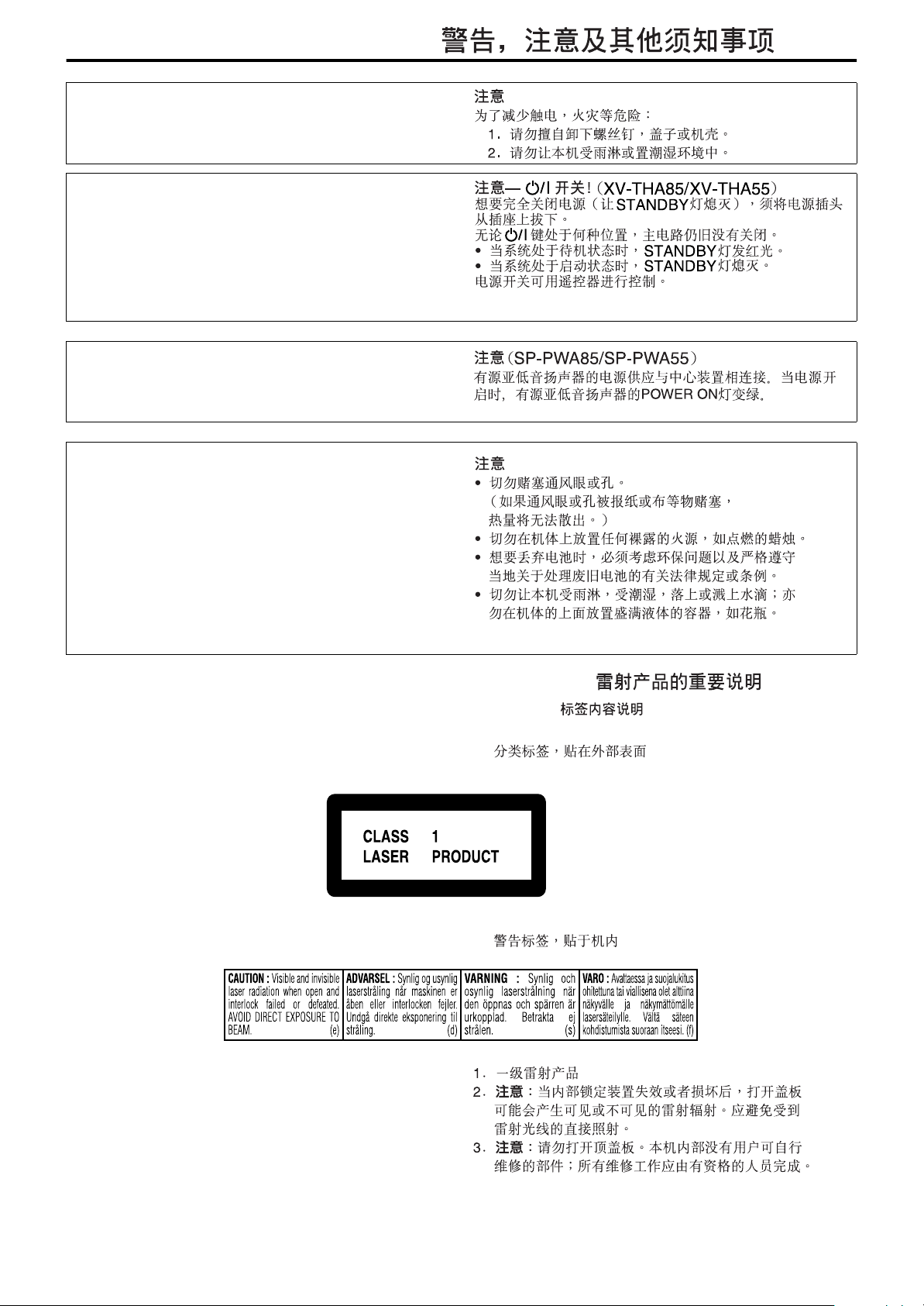
IMPORTANT FOR LASER PRODUCTS /
REPRODUCTION OF LABELS /
AAAA
CLASSIFICATION LABEL, PLACED ON EXTERIOR
SURFACE
2222
WARNING LABEL, PLACED INSIDE THE UNIT
1. CLASS 1 LASER PRODUCT
2.
CAUTION
interlock failed or defeated. Avoid direct exposure to beam.
3.
CAUTION
serviceable parts inside the Unit; leave all servicing to qualified
service personnel.
: Visible and invisible laser radiation when open and
: Do not open the top cover. There are no user
AAAA
2222
G-1
Page 3
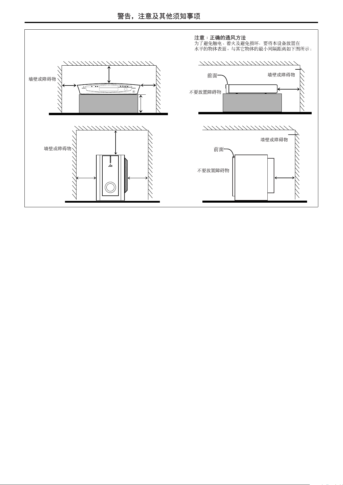
XV-THA85/XV-THA55
Wall or obstructions
10 cm
Front
No obstructions
SP-PWA85/SP-PWA55
15 cm
Wall or obstructions
Front
No obstructions
Warnings, Cautions and Others /
Caution: Proper Ventilation
To avoid risk of electric shock and fire and to protect from damage, place
the apparatus on a level surface. The minimal clearances are shown below:
Wall or
obstructions
obstructions
Wall or
XV-THA85/
XV-THA55
SP-PWA85/
SP-PWA55
15 cm 15 cm
8 cm
3 cm3 cm
15 cm
20 cm
G-2
Page 4

Table of contents
Introduction...................................... 2
Notes on handling..................................................................2
Supplied accessories .............................................................2
English
About discs ......................................3
Playable disc types ................................................................3
Disc structure ........................................................................4
Playback Control function (PBC) — VCD and SVCD only ......4
Names of parts and controls ...........5
Getting started................................. 8
Connections...........................................................................8
Using the remote control .....................................................16
Basic operations ............................ 19
Turning the system on/off....................................................19
Selecting the source to play.................................................20
Adjusting the volume ...........................................................20
Listening with headphones ..................................................20
Turning off the sound temporarily .......................................20
Adjusting the brightness ......................................................21
Using the Sleep Timer..........................................................21
Adjusting the output level of the subwoofer.........................21
Changing the decode mode .................................................22
Changing the scan mode .....................................................22
Adjusting the bass/treble sound...........................................22
Playback......................................... 23
Basic playback .....................................................................23
Playback features.................................................................25
Tuner operations............................ 27
Setting the AM tuner interval spacing ..................................27
Manual tuning......................................................................27
Preset tuning .......................................................................27
Selecting the FM reception mode.........................................28
Reducing the noise of AM broadcast ...................................28
Creating realistic sound fields ......29
Using the surround mode ....................................................31
Adjusting the sound.............................................................32
Advanced operations ..................... 33
Using the on-screen bar ......................................................33
Playing from a specified position on a disc..........................34
Using the MP3 control display.............................................36
Using the JPEG control display............................................37
Selecting a view angle of DVD .............................................38
Selecting the subtitle/audio languages.................................39
Special picture playback ......................................................41
Program Playback................................................................43
Random Playback................................................................44
Repeat Playback ..................................................................44
Setting DVD preferences ...............46
Using the choice menus ......................................................46
Menu description.................................................................48
Parental Lock.......................................................................51
System setting ............................... 54
AV COMPU LINK remote control
system ............................................55
References ..................................... 56
Maintenance ........................................................................56
Trouble shooting..................................................................56
Glossary...............................................................................59
Index....................................................................................60
Specifications ......................................................................61
1
Page 5
Introduction
Notes on handling
7
Important cautions
Installation of the system
• Select a place which is level, dry and neither too hot nor too cold;
between 5°C and 35°C (41°F and 95°F).
• Leave sufficient distance between the system and the TV.
• Do not use the system in a place subject to vibration.
Power cord
• Do not handle the power cord with wet hands!
• A small amount of power (2.5 watts) is always consumed while
the power cord is connected to the wall outlet (center unit only).
• When unplugging the power cord from the wall outlet, always
pull on the plug, not the power cord.
To prevent malfunctions of the system
• There are no user-serviceable parts inside. If anything goes
wrong, unplug the power cord and consult your dealer.
• Do not insert any metallic object into the system.
• Do not use any non-standard shape disc (like a heart, flower or
credit card, etc.) available on the market, because it may damage
the system.
• Do not use a disc with tape, stickers, or paste on it, because it
may damage the system.
Label sticker
7
Safety precautions
Avoid moisture, water and dust
Do not place the system in moist or dusty places.
Avoid high temperatures
Do not expose the system to direct sunlight and do not place it near
a heating device.
When you are away
When away on travel or for other reasons for an extended period of
time, disconnect the power cord plug from the wall outlet.
Do not block the vents
Blocking the vents may damage the system.
Care of the cabinet
When cleaning the system, use a soft cloth and follow the relevant
instructions on the use of chemically-coated cloths. Do not use
benzene, thinner or other organic solvents including disinfectants.
These may cause deformation or discoloring.
If water gets inside the system
Turn the system off and disconnect the power cord plug from the
wall outlet, then call the store where you made your purchase.
Using the system in this condition may cause fire or electrical
shock.
Supplied accessories
English
Sticker
Paste
Note about copyright laws
Check the copyright laws in your country before recording from
DVDs, Super Video CDs (SVCDs), Video CDs (VCDs) and Audio
CDs. Recording of copyrighted material may infringe copyright
laws.
Note about copyguard system
DVDs are protected by copyguard system. When you connect the
system to your VCR directly, the copyguard system activates and
the picture may not be played back correctly.
Check to be sure you have all of the supplied accessories.
The number in parentheses is the quantity of the pieces supplied.
If anything is missing, contact your dealer immediately.
• Remote control (1)
• Batteries (2)
• FM antenna (1)
• AM loop antenna (1)
•Power cord (1)
• System cord (1)
• Composite video cord (1)
• Speaker cords
5 m: For satellite (front left/right) and center speakers (3)
10 m: For satellite speakers (surround left/right) (2)
(Length of speaker cords is approximate.)
• Screws (with washer) (TH-A85 only)
M4 x 25 mm: For satellite speakers (16)
• AC plug adaptor (2) (not supplied for Hong Kong)
This product incorporates copyright protection technology that is protected by method claims of certain U.S. patents and other
intellectual property rights owned by Macrovision Corporation and other rights owners. Use of this copyright protection
technology must be authorized by Macrovision Corporation, and is intended for home and other limited viewing uses only
unless otherwise authorized by Macrovision Corporation. Reverse engineering or disassembly is prohibited.
2
Page 6
About discs
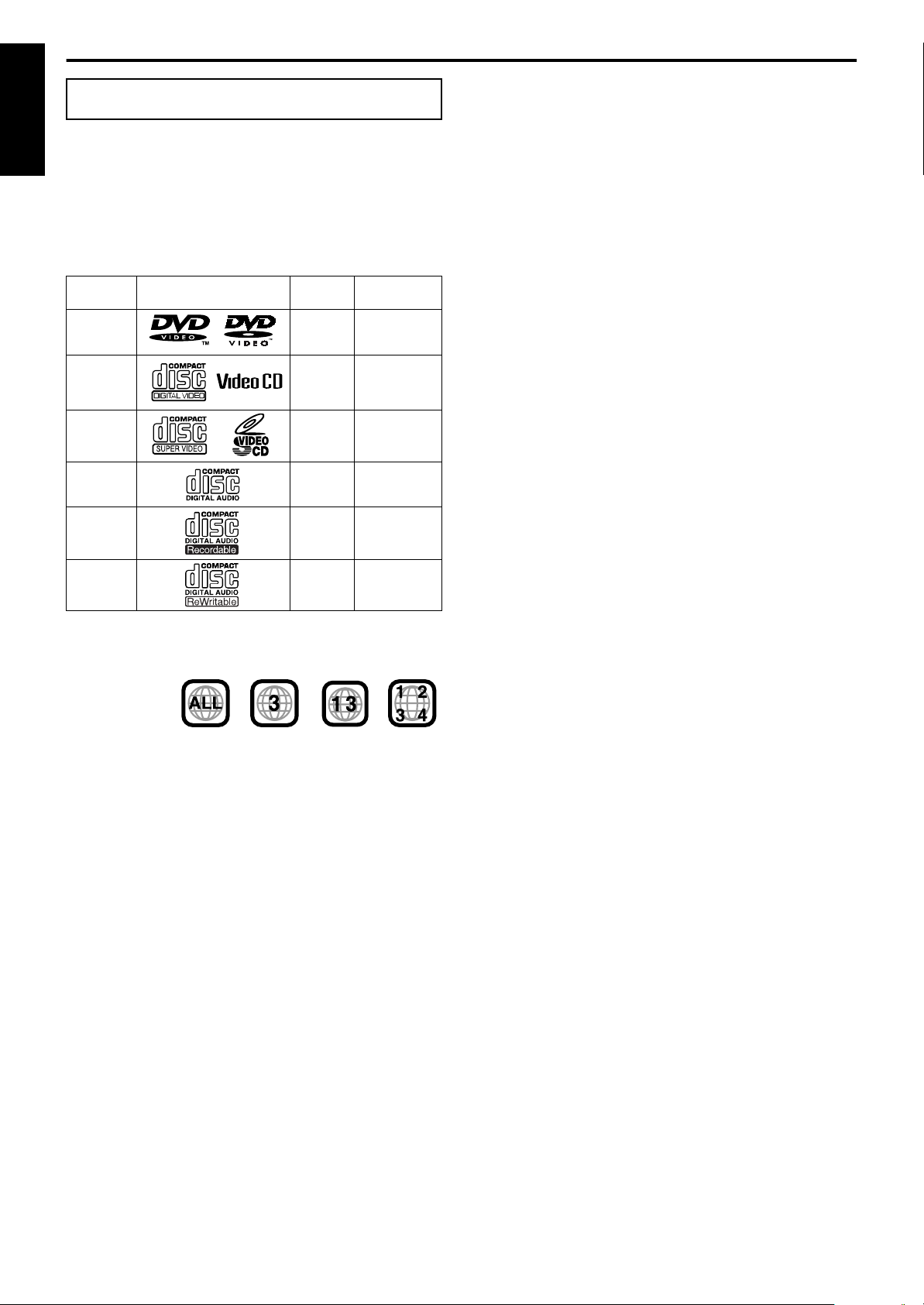
Playable disc types
This system has been designed to play back the following discs:
English
DVD Video (DVD), Video CD (VCD), Super Video CD (SVCD),
Audio CD, CD-R and CD-RW.
• This system can also play back MP3 and JPEG files recorded on
CD-Rs and CD-RWs. (A pg. 23)
• This system can also play back finalized DVD-Rs recorded in
DVD VIDEO format. However, some discs may not be played
back because of their disc characteristics or recording conditions.
Discs you can play:
Disc Type Mark (Logo)
DVD
VCD
SVCD
Audio CD — —
CD-R — —
CD-RW — —
* Note on Region Code
DVD players and DVDs have their own Region Code numbers. This
system can only play back DVDs recorded with the color system of
NTSC or PAL whose Region Code number includes “3”.
Examples:
If a DVD with an improper Region Code number is loaded,
“REGION CODE ERROR!” appears on the TV screen and playback
cannot start.
• The following discs cannot be played back:
DVD Audio, DVD-ROM, DVD-RAM, DVD-RW, CD-ROM,
CD-I (CD-I Ready), Photo CD, etc.
Playing back these discs will generate noise and damage the
speakers.
• On some DVDs, Video CDs or SVCDs, their actual
operation may be different from what is explained in this
manual. This is due to the disc programming and disc
structure, not a malfunction of this system.
Notes on CD-R and CD-RW
• User-edited CD-Rs (Recordable) and CD-RWs (Rewritable) can
be played back only if they are already “finalized”.
• This system can play back CD-Rs or CD-RWs recorded on a
personal computer if they have been recorded in the audio CD
format.
This system can also play back CD-Rs or CD-RWs if MP3 files
or JPEG files are recorded on them.
However, some discs may not be played back because of their
disc characteristics, recording conditions, or damage or stain on
them.
Video
Format
NTSC/
PA L
NTSC/
PA L
NTSC/
PA L
Region Code
Number
3/ALL
—
—
Especially, the configuration and characteristics of an MP3 disc
or a JPEG disc are determined by the writing (encoding) software
and hardware used for recording. Therefore, due to the software
and hardware used, the following symptoms may occur:
Some discs may not be played back.
•
Some tracks on an MP3 disc may be skipped or may not be
•
played back normally.
Some files on a JPEG disc may be played back distortedly.
•
• Before playing back CD-Rs or CD-RWs, read their instructions
or cautions carefully.
• CD-RWs may require a longer readout time. This is caused by
the fact that the reflectance of CD-RWs is lower than that of
regular CDs.
*
About MP3 discs
MP3 is an abbreviation for Motion Picture Experts Group 1 (or
MPEG-1) Audio Layer 3. MP3 is simply a compressed data file
format. By using MP3 format, one CD-R or CD-RW can contain 10
times as much data as one regular CD.
About JPEG discs
A still-picture data compression system proposed by the Joint
Photographic Expert Group, which features small decrease in
image quality in spite of its high compression ratio.
Notes on MP3/JPEGs discs
• MP3/JPEG discs (either CD-R or CD-RW) require a longer
readout time. (It differs due to the complexity of the directory/file
configuration.)
• When making an MP3/JPEG disc, select ISO 9660 Level 1 or
Level 2 for the disc format.
• This system supports “multi-session” discs (up to 5 sessions).
• This system cannot play “packet write” discs.
• The system can only play MP3/JPEG files with the following file
extensions;
MP3: “.MP3”, “.Mp3”, “.mP3” and “.mp3”
JPEG: “.jpg”, “.jpeg”, “.JPG”, “.JPEG” and any uppercase and
lowercase combination (such as “.Jpg”)
• If both MP3 files and JPEG files are recorded on a disc, set the
MP3/JPEG setting in the PICTURE menu to the appropriate
setting for the data to be read (“MP3” or “JPEG”). (A pg. 49)
• Some MP3/JPEG discs may not be played back because of their
disc characteristics or recording conditions.
Notes on MP3 discs only
• ID3* tags cannot be shown on the display.
* An MP3 file can contain file information called an “ID3 Tag”
where its album name, performer, track title, etc. are recorded.
There are two versions, ID3v1 (ID3 Tag version 1) and ID3v2
(ID3 Tag version 2).
• We recommend to record each piece of material (song) at a
sample rate of 44.1 kHz and at a data transfer rate of 128 kbps.
• Some tracks on an MP3 disc may be skipped or may not be
played back normally.
Notes on JPEG discs only
• We recommend to record a file at 640 x 480 resolution. (If a file
has been recorded at a resolution of more than 640 x 480, it will
take a longer time to be displayed.)
• This system can only play baseline JPEG files*. Progressive
JPEG files* or lossless JPEG files* cannot be played.
* Baseline JPEG format: Used for digital cameras, web, etc.
Progressive JPEG format:Used for web.
Lossless JPEG format: An old type and rarely used now.
• Some files on a JPEG disc may be played back distortedly.
3
Page 7
About discs
NOTE
Submenu
Menu screen
A: Moving picture
B: Still picture
Press RETURN.
Press RETURN.
Press
RETURN.
IMPORTANT
Before playing a disc, make sure of the following;
• Check the connection with the TV.
• Turn on your TV and select the correct input mode on the TV to view
the pictures or on-screen information on the TV screen.
• For DVD playback, you can change the initial setting to your
preference. (Apg. 46 – 53)
If B appears on the TV screen when pressing a button;
The disc cannot accept the operation you have tried to do, or the
information required for that operation is not recorded on the
disc.
NOTICE: In some cases, without showing B, operations will not
be accepted.
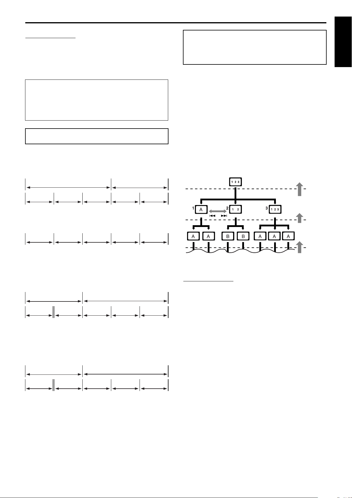
Disc structure
DVD
A DVD consists of “titles” and each title may be divided into
“chapters”.
For example, if a DVD contains movies, each movie may have its
own title number and may be further divided into chapters.
Title 1 Title 2
Chapter 1 Chapter 2 Chapter 3 Chapter 1 Chapter 2
Playback Control function
(PBC) — VCD and SVCD
only
The Playback Control function allows you to enjoy menu-driven
operation and high-resolution still images which have a resolution
four times greater than moving pictures.
High-resolution still image display
You can display high-quality images which are four times clearer
than moving pictures.
Menu-driven playback
A selection menu is displayed when you start playing a Video CD
or SVCD with the Playback Control feature. The selection menu
shows a list of numbers for selection. Some discs may show
moving pictures or a divided screen.
You can interact with the screen using a menu display to select and
play an entry.
See example illustration below about basic features of menu-driven
playback (for details about the operation through the menu, also see
page 35).
English
Video CD/SVCD/Audio CD
A Video CD, SVCD, Audio CD consists of “tracks”.
In general, each track has its own track number. (On some discs,
each track may also be further divided by indexes.)
Track 1Track 2Track 3Track 4Track 5
MP3 discs
On an MP3 disc, each song is recorded as a track (file). Tracks are
usually grouped into a group (folder). Groups can also include
other groups, creating hierarchical group layers. This system can
recognize up to 150 tracks per group and up to 99 groups per disc.
• If there is any type of file other than MP3 files in a group
(folder), those files are also counted in the total number of 150.
Group 1 Group 2
Track 1 Track 2 Group 3 Group 4 Group 5
JPEG discs
On a JPEG disc, each still picture is recorded as a file. Files are
usually grouped into a group (folder). Groups can also include
other groups, creating hierarchical folder layers. This system can
recognize up to 150 files per group and up to 99 groups per disc.
• If there is any type of file other than JPEG files in a group
(folder), those files are also counted in the total number of 150.
Group 1 Group 2
• When operating a Video CD or SVCD using the menu, some
functions such as Repeat Playback may not work.
File 1 File 2 Group 3 Group 4 Group 5
4
Page 8
Names of parts and controls
The illustrations of the center unit and the subwoofer used in this manual are of TH-A85 unless otherwise noted.
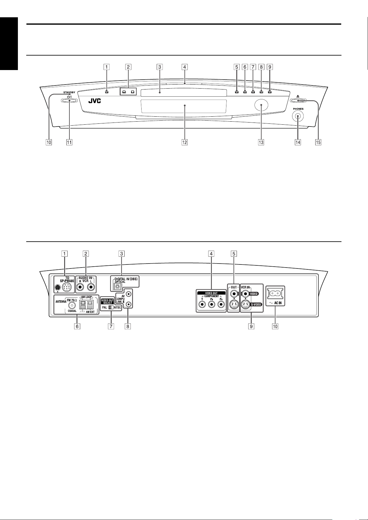
Front panel (center unit)
English
A
Source button (SOURCE) Apg. 20
B
Volume buttons (VOLUME +/–) Apg. 20
C
Disc tray Apg. 23
D
Illumination lamp Apg. 21
E
Stop button (
F
Play button (
G
Pause button (
H
Reverse skip button (
7
) Apg. 23
3
) Apg. 23
8
) Apg. 23
4
) Apg. 26
Rear panel (center unit)
I
Forward skip button (
J
Standby lamp (STANDBY) Apg. 19
K
Standby-on button (
L
Display window Apg.6,24
M
Remote sensor Apg. 16
N
Headphones jack (PHONES) Apg. 20
O
Open/close button (
¢
F
) Apg. 19
0
) Apg. 23
) Apg. 26
A
System cord connector Apg. 10
B
Audio input jacks (AUDIO IN VCR) Apg. 14
C
Digital input jack (DIGITAL IN (DBS)) Apg. 14
D
Video output jacks (VIDEO OUT) Apg. 8
COMPONENT (Y, P
E
Video output jacks (OUT) Apg. 8
VIDEO, S-VIDEO
F
Antenna terminals (ANTENNA) Apg. 9
G
Video output signal switch (VIDEO OUT SELECT)
A
pg. 8
PAL , N TSC
H
AV COMPU LINK-III jacks Apg. 55
I
Video input jacks (VCR IN) Apg. 14
VIDEO, S-VIDEO
J
Ó
AC IN socket Apg. 15
B,PR)
5
Page 9
Names of parts and controls
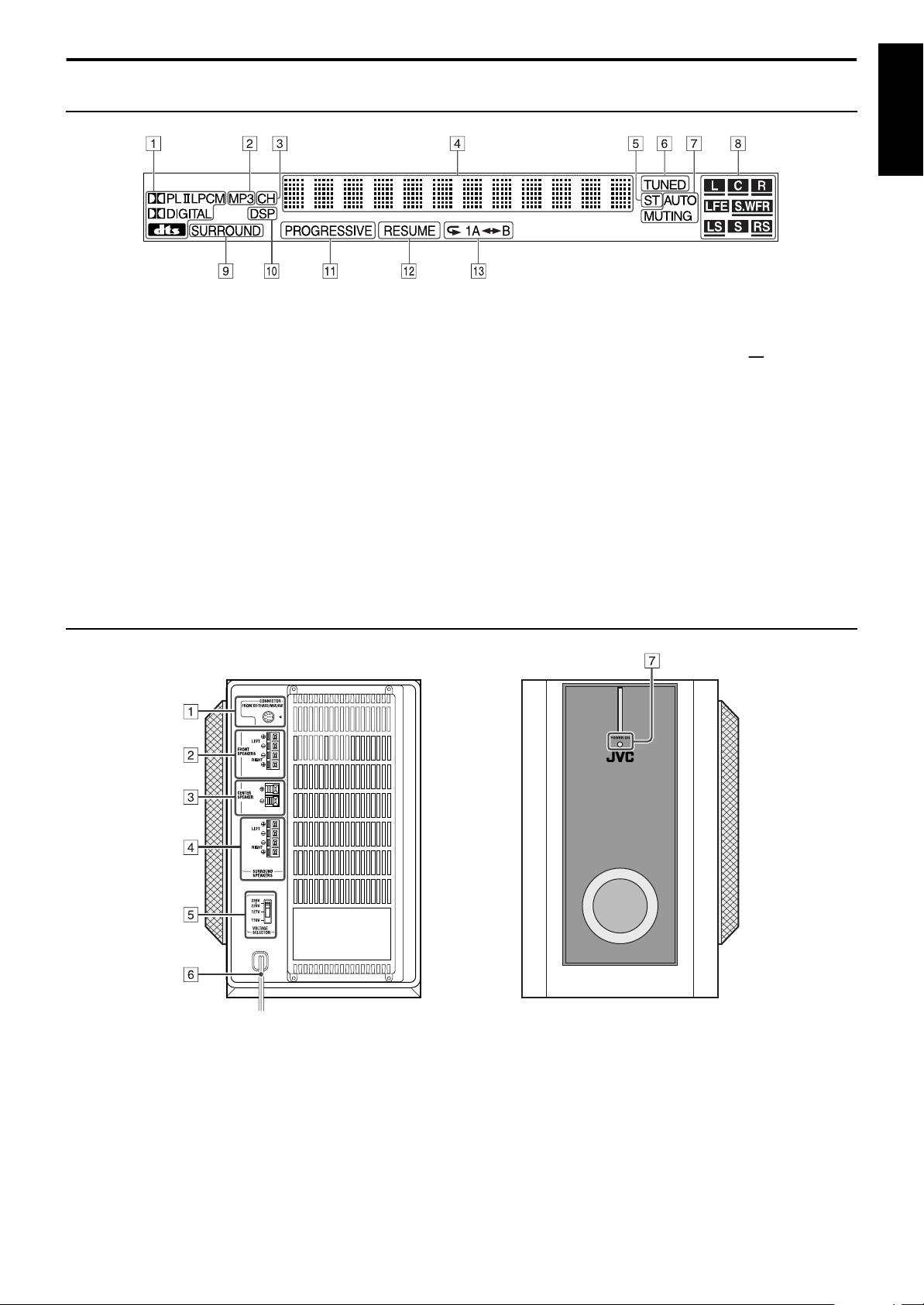
Display window (center unit)
English
A •
Dolby Pro Logic II indicator (GPLII) Apg. 29
•
Linear PCM indicator (LPCM) Apg. 30
•
Digital signal format indicators Apg. 30
Dolby Digital (
B
MP3 indicator Apg. 24
C
Channel indicator (CH) Apg. 28
D
Main display Apg. 24
E
Stereo indicator (ST) Apg. 27
F
Tuning indicator (TUNED) Apg. 27
G
Auto muting indicator (AUTO MUTING) Apg. 28
G
DIGITAL), DTS (C)
Powered subwoofer
H
•
Source signal indicators (
A
pg. 30
•
Subwoofer indicator (
•
Sound reproducing speaker indicator ( ) Apg. 30
I
Surround indicator (SURROUND) Apg. 31
J
DSP indicator Apg.29–31
K
Progressive mode indicator (PROGRESSIVE) Apg. 22
L
Resume indicator (RESUME) Apg. 24
M
Repeat mode indicators Apg. 44
abcdghi
f
) Apg. 30
)
Rear Front
A
System cord connector Apg. 10
B
Front speaker terminals (FRONT SPEAKERS) Apg. 12, 13
C
Center speaker terminals (CENTER SPEAKER) Apg. 12, 13
D
Surround speaker terminals (SURROUND SPEAKERS) Apg. 12, 13
E
Voltage selector switch (VOLTAGE SELECTOR) (except for Hong Kong) Apg. 15
F
Power cord Apg. 15
G
Power lamp (POWER ON) Apg. 19
6
Page 10
Names of parts and controls
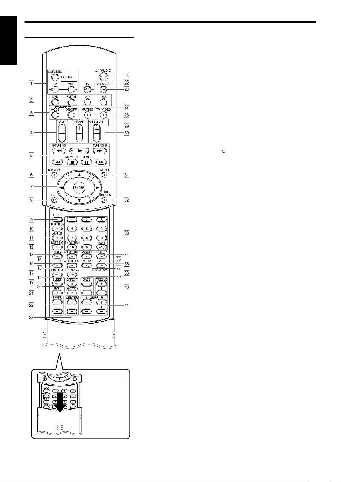
Remote control
English
NOTE
• To use buttons 9 –
and g – o, slide
W
down the remote
control cover.
A
Remote control mode selecting buttons (CONTROL) Apg.17–47
CATV/DBS, TV, VCR
B
Source selecting buttons Apg. 20
DVD, FM/AM, VCR, DBS
C
Surround buttons (SURR)
Mode (MODE), On/Off (ON/OFF) Apg. 31
D
TV volume buttons (TV VOL +/–) Apg. 17
E
Operating buttons
•
Play button (3) Apg. 24
•
Forward/reverse skip buttons (¢/4) Apg. 26
•
Fast-forward/reverse playback buttons (¡/1) Apg. 26
•
Stop button (7) Apg. 23
•
Pause button (8) Apg. 23
•
Tuning buttons (TUNINGª, TUNING·) Apg. 27
•
Memory button (MEMORY) Apg. 28
•
FM reception/Beat Cut mode button (FM MODE) Apg. 28
F
Top menu button (TOP MENU) Apg. 34
G
•
Cursor buttons (3/2///5) Apg. 34
•
Enter button (ENTER) Apg. 17
H •
One Touch Replay button ( ) Apg. 25
•
Record button (REC) Apg. 18
I
Audio button (AUDIO) Apg. 39, 40
J
Subtitle button (SUBTITLE) Apg. 39
K
Angle button (ANGLE) Apg. 38
L
Setting button (SETTING) Apg. 54
M
Choice menu button (CHOICE) Apg. 46
N
Group/title button (GROUP/TITLE) Apg. 35
O
Repeat button (REPEAT) Apg. 44
P
A-B repeat button (A-B REPEAT) Apg. 45
Q
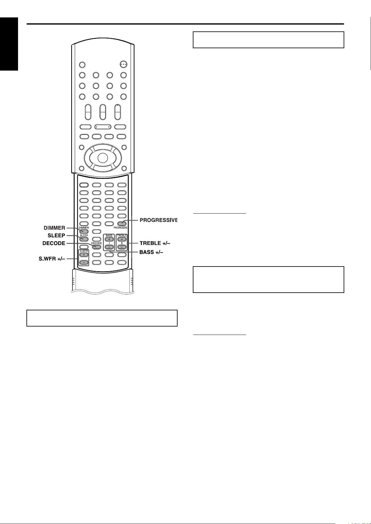
Dimmer button (DIMMER) Apg. 21
R
Effect button (EFFECT) Apg. 32
S
Sleep button (SLEEP) Apg. 21
T
Decode mode button (DECODE) Apg. 22
U
Test tone button (TEST) Apg. 32
V
Subwoofer adjustment buttons (S.WFR +/–) Apg. 21
W
Center speaker adjustment buttons (CENTER +/–) Apg. 32
X
Standby-on button (
Y
Standby-on button (
Z
Standby-on button (
a
Muting button (MUTING) Apg. 20
b
TV/Video mode button (TV/VIDEO) Apg. 17
c
Channel buttons (CHANNEL +/–) Apg. 17
d
Volume buttons (AUDIO VOL +/–) Apg. 20
e
Menu button (MENU) Apg. 34
f
On-screen button (ON SCREEN) Apg. 33
g
•
Number buttons Apg. 17, 26, 35
•
TV returning button (TV RETURN) Apg. 17
h
Return button (RETURN) Apg. 4, 35
i
Cancel button (CANCEL) Apg. 43
j
•
VFP setting button Apg. 42
•
Progressive mode button (PROGRESSIVE) Apg. 22
k
Zoom button (ZOOM) Apg. 41
l
Display window button (FL DISPLAY) Apg. 24
m
Bass adjustment buttons (BASS +/–) Apg. 22
n
Treble adjustment buttons (TREBLE +/–) Apg. 22
o
Surround speaker adjustment buttons (SURR) Apg. 32
F
AUDIO) Apg. 19
F
TV) Apg. 17
F
VCR/DBS) Apg. 17
Left (L +/–), Right (R +/–)
7
Page 11
Getting started
Connections
• Do not connect the AC power cord until all other connections have been made.
• Since different components often have different terminal names, carefully read the instructions supplied with the components you are going
to connect.
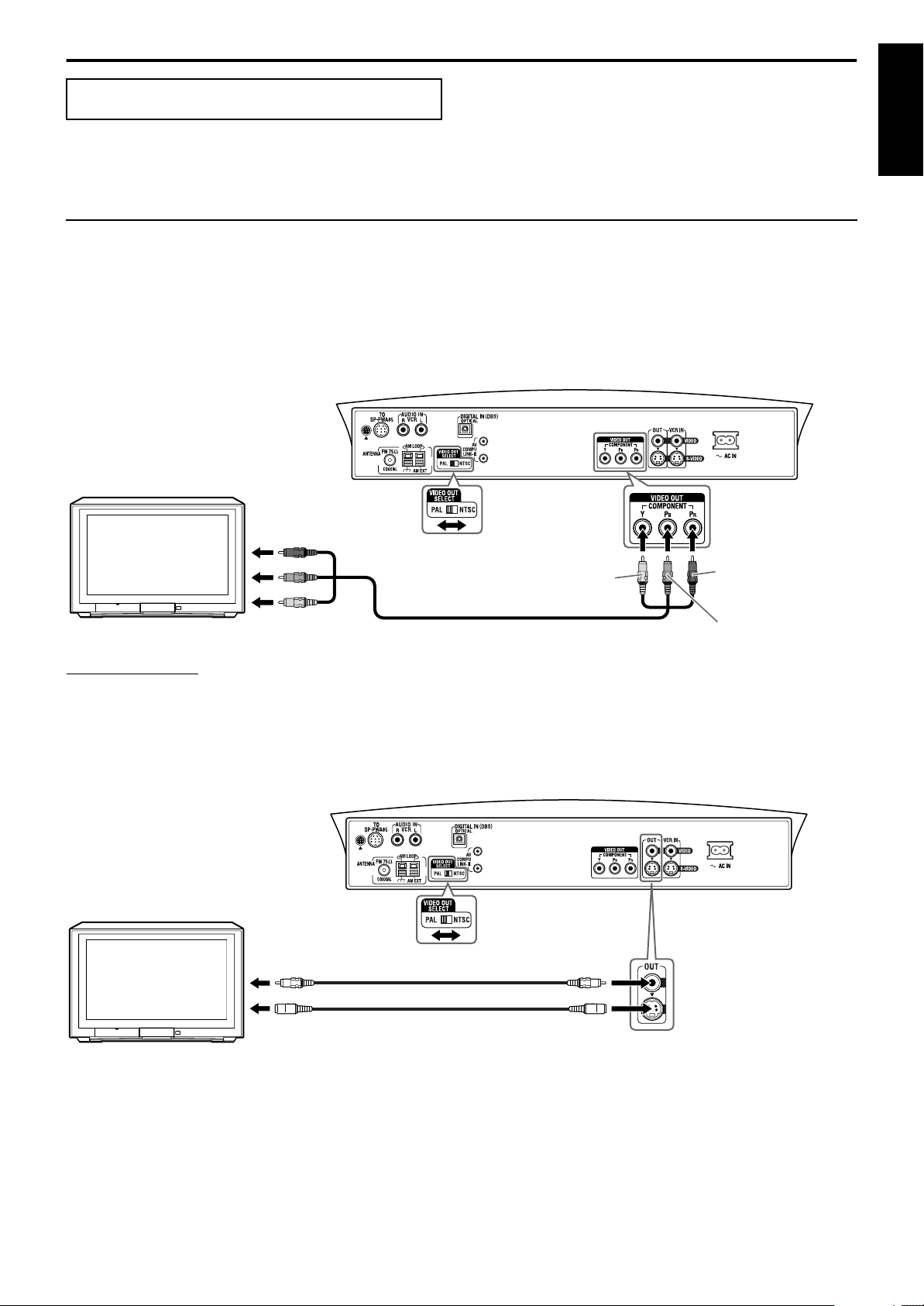
Connecting a TV
To view pictures and on-screen displays, connect the TV to the center unit.
• You can get better picture quality in the order — Component video > S-video > Composite video.
• Distortion of picture may occur when connecting to the TV via a VCR, or to a TV with a built-in VCR.
• You need to set “MONITOR TYPE” in the PICTURE menu correctly according to the aspect ratio of your TV. (A pg. 49)
7
To connect a TV through the component video input jacks
If your TV has component video input jacks, connect them using a component video cord (not supplied) to view a high quality picture.
• Connect “Y” to “Y”, “P
• If your TV supports progressive video input, you can enjoy a high quality picture by setting the progressive scan mode to active. (A pg. 22)
TV
” to “PB”, “PR” to “PR” correctly.
B
To component video input
VIDEO OUT
SELECT switch
(See below.)
Green
Component video cord (not supplied)
Center unit
Red
English
Blue
NOTE
• If the component video input jacks of your TV are of the BNC type, use a plug adapter (not supplied) to convert the pin plugs to BNC plugs.
• The component video signals can be output only when you select “DVD” as the source to play. (Apg. 20)
7
To connect a TV through the composite or S-video jacks
Connect the TV using the composite video cord (supplied) or an S-video cord (not supplied).
If your TV has an S-video (Y/C-separation) jack, you can get better picture quality than by using composite video connection.
• Connect the S-video cord by matching the / mark on the plug to the one on the rear of the center unit.
TV
7
Selecting the color system
The center unit is compatible with the PAL and NTSC systems. Set the VIDEO OUT SELECT switch on the rear panel in standby mode to
match the color system of your TV. Make sure that the color system of a DVD, Video CD, or SVCD disc labeled on the package matches your
TV.
• If you use a multi-system TV, by setting “MONITOR TYPE” in the PICTURE menu to an appropriate “MULTI” option, the system outputs
a video signal by the same format recorded on the disc (i.e. if you play an NTSC disc, the system outputs a signal by the NTSC format)
regardless of the VIDEO OUT SELECT switch setting. (A pg. 49).
VIDEO OUT SELECT
switch (See below.)
To composite video input
To S-video input
Composite
video cord
(supplied)
or
S-video cord (not supplied)
Center unit
8
Page 12
Getting started
NOTE
Outdoor single vinyl-covered wire
antenna (not supplied)
AM loop antenna
Extend the supplied FM
antenna horizontally.
Center unit
Outdoor FM antenna
(not supplied)
Outdoor FM antenna cord
(not supplied)
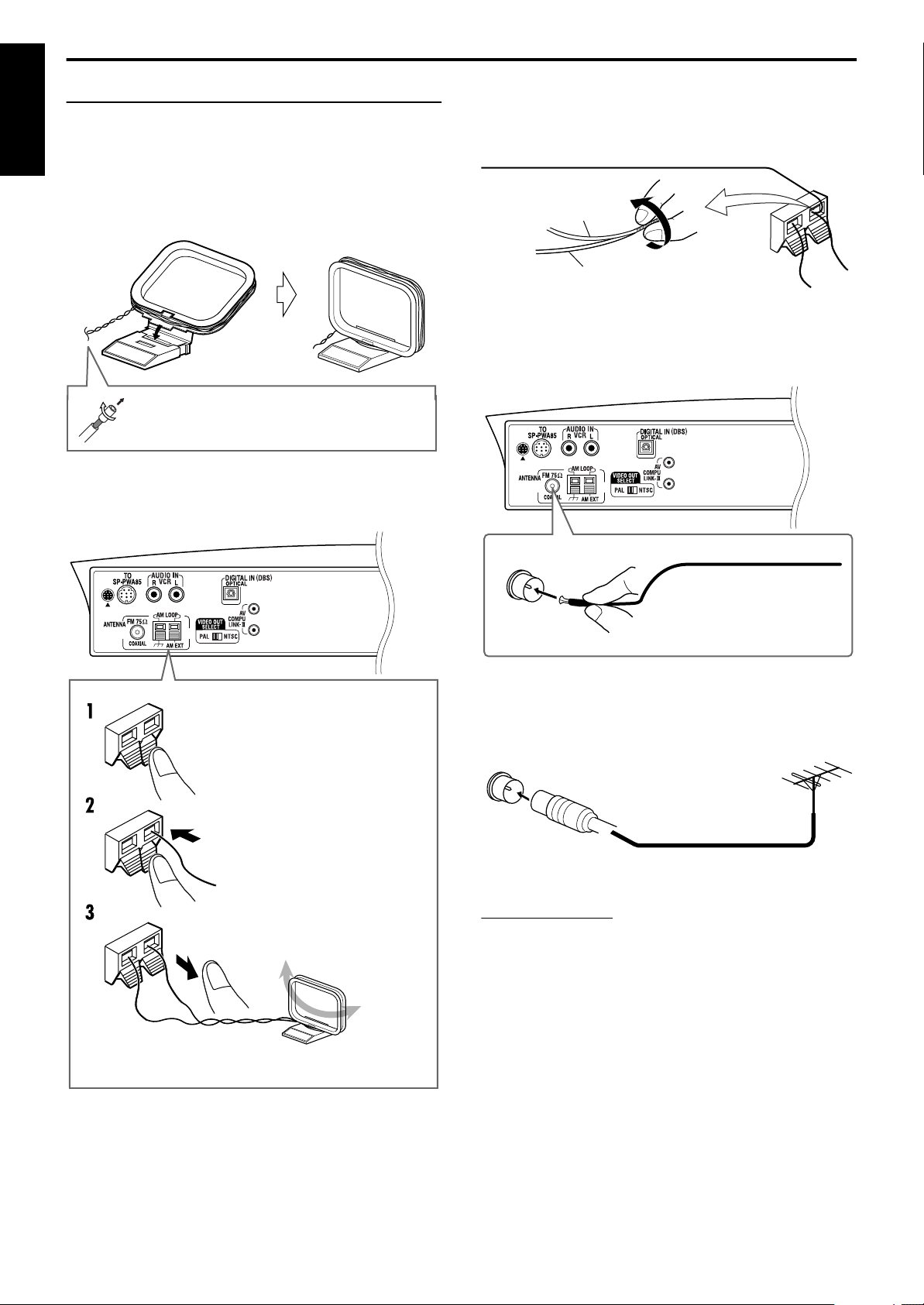
Connecting the FM and AM antennas
Make sure the antenna conductors do not touch any other terminals,
connecting cords and power cords. This could cause poor reception.
English
7
AM loop antenna
Setting up supplied AM loop antenna
Attach the AM loop to its base by snapping the tabs on the loop into
the slot on the base.
If the antenna cord is covered with the insulation
coat, twist and pull the insulation coat off and
remove.
Connecting AM loop antenna
Center unit
If reception is poor
Connect an outdoor single vinyl-covered wire antenna (not
supplied) to the AM EXT terminal. (Keep the AM loop antenna
connected.)
• Twist together both wires.
7
FM antenna
Connecting supplied FM antenna
Press and hold down the terminal
clamp.
Insert the antenna cord.
Release finger from the clamp.
• Turn the loop antenna until you have the best reception.
If reception is poor
Connect an outdoor FM antenna with standard type (75 C coaxial)
connector.
• Disconnect the supplied FM antenna before attaching a 75 C coaxial
connector (the kind with a round wire going to an outdoor antenna).
• We recommend that you use coaxial cable for the FM antenna as it is
well-shielded against interference.
9
Page 13
Getting started
NOTE
Front rightFront left
Center speaker
Powered subwoofer
Surround
left
Surround right
TH-A85
Front rightFront left
Center
speaker
Powered
subwoofer
Surround left Surround right
TH-A55
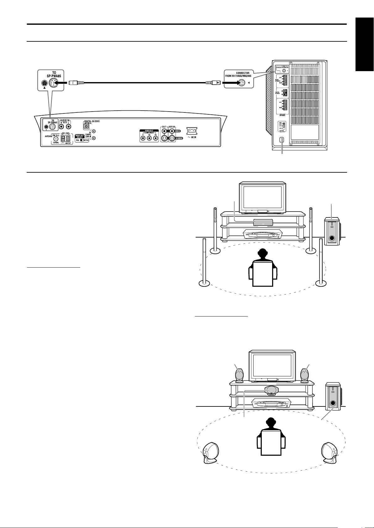
Connecting the powered subwoofer
Connect the supplied powered subwoofer (SP-PWA85/SP-PWA55) using the system cord (supplied).
• Connect the system cord by matching the 5 marks on the plugs to the ones on the center unit and powered subwoofer.
System cord (supplied)
English
Ensure that the
on the plug faces down.
5
mark
Connecting the satellite speakers
7
Speaker layout
When positioning the speakers, to obtain the best possible sound
from this system you need to place all satellite speakers at the same
distance from the listening position with the front of each speaker
facing toward the listener.
When you cannot place them at the same distance from the
listening position, you can make adjustment so that
speakers operate as if they are placed at the best position.
(
pg. 50)
AAAA
• Normally place the powered subwoofer in front of you. (Since
bass sound is non-directional, you do not need to place it at the
same distance as the other speakers.)
NOTE
• Although the satellite speakers and the powered subwoofer are
magnetically shielded, the TV screen may appear mottled. In this
case, keep the distance between them to the TV to over 10 cm.
• For safety reasons, always ensure that there is sufficient space behind
the powered subwoofer.
• When you position the satellite speakers in a relatively high place,
such as the top of your bookshelf, place them on a flat and level
surface.
• Speaker grilles are not removable (except SP-THA55C, SP-THA55F,
and SP-THA55S). Trying to remove them by force may damage
them.
• Be sure to place the powered subwoofer to the TV’s right. If you place
the powered subwoofer to the TV’s left, keep sufficient distance
between them to prevent the TV from appearing mottled.
Powered
subwoofer
Center unit
Only for TH-A85
• Do not lean against the satellite speakers, as the speakers could fall
down or break, possibly causing injury. Especially be careful not to
let children lean against them.
10
Page 14
Getting started
NOTE
Speaker section
Stand
Screws (4)
(supplied,
M4 x 25 mm)
Cushion (not supplied)
7
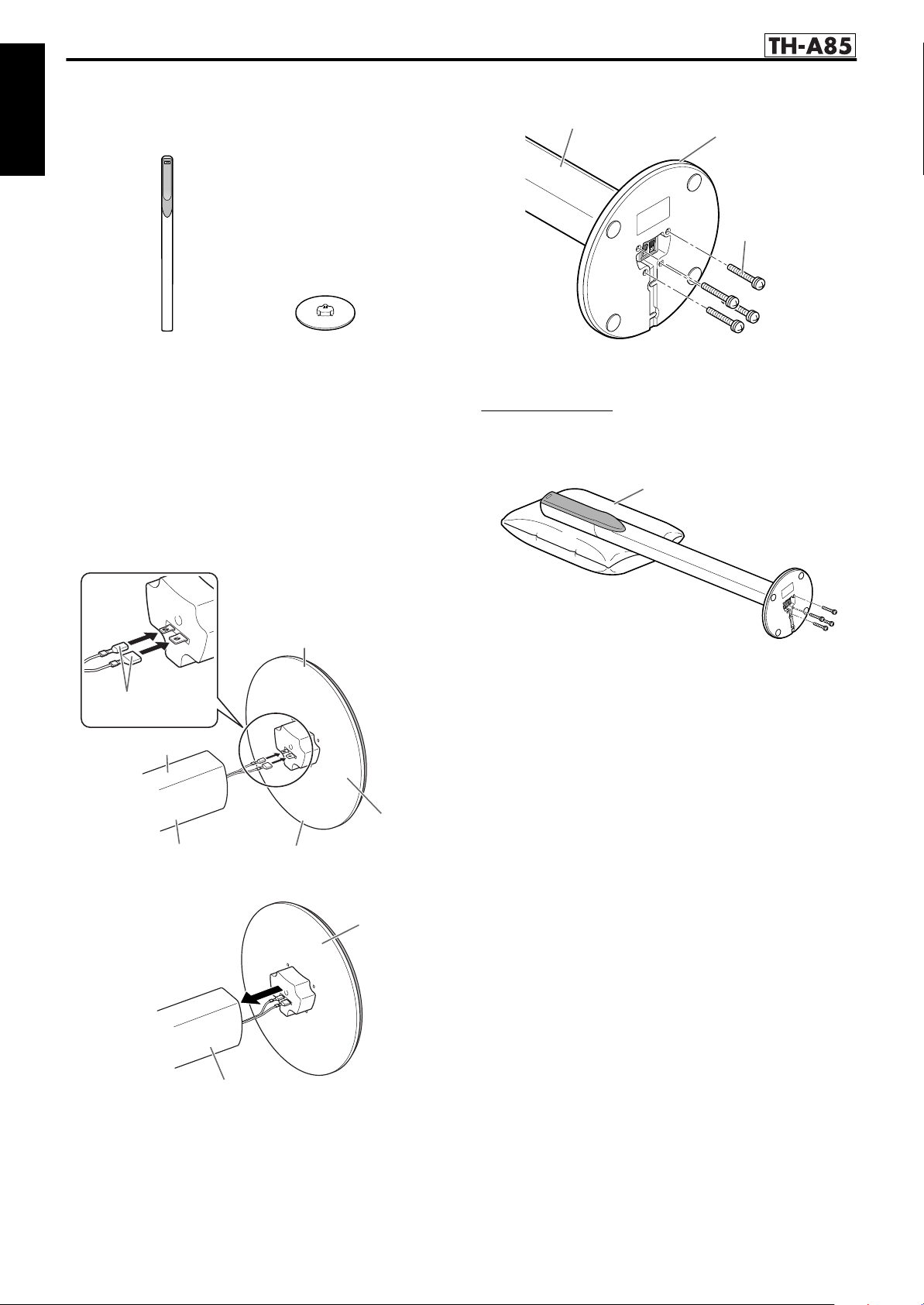
Assembling the satellite speakers (TH-A85 only)
Each speaker (except the center speaker) has been divided into two
parts for shipment. Before connecting the satellite speakers, first
assemble them by following the procedure below.
English
This page is for
3 Fix the stand to the speaker section.
• Be sure to tighten the screws firmly.
Speaker section
Before assembling —
• Prepare a Phillips screwdriver.
• Take care not to drop the stand while assembling; otherwise, it
may cause damage to the floor or injury.
• Ensure enough space exists for assembly and installation.
• Spread a large, thick cloth on the floor where you assemble the
speakers, so you can protect the floor and the speaker itself.
Stand
1 Connect the speaker connectors to the
stand connectors.
• Be sure to connect the speaker connectors by matching their
sizes.
Front
Speaker connectors
Front
Repeat the procedure from step 1 to assemble the other satellite
speakers.
• Use the speaker after assembly is fully and correctly done.
• It is recommended to place a cushion under the speaker section.
You can tighten the screws easily by placing the speaker section
horizontally.
Stand
Speaker section
Rear
2 Join the stand to the speaker section.
Stand
11
Speaker section
Page 15
Getting started
7
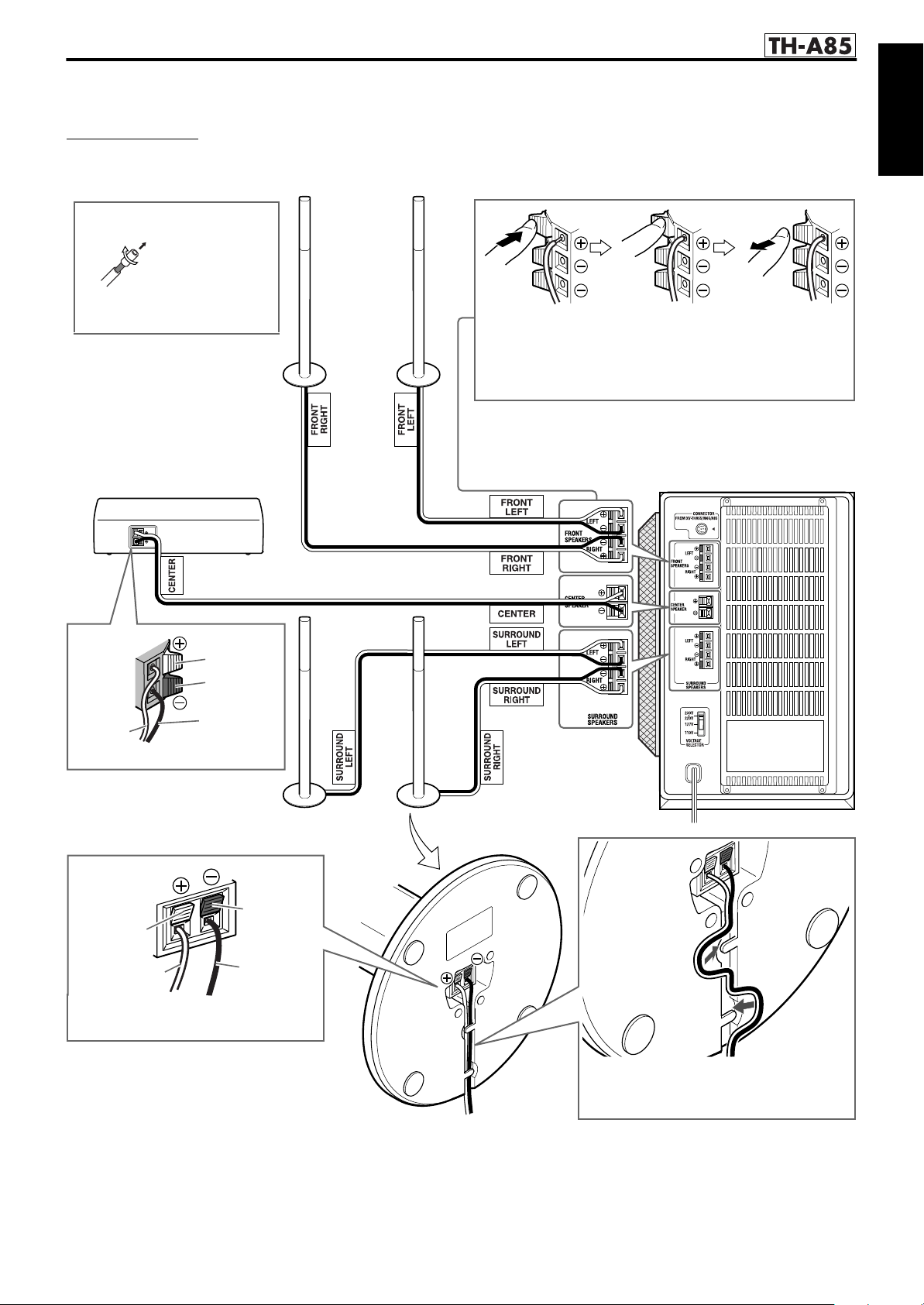
Connecting the satellite (front, center, surround) speakers (TH-A85)
Each speaker (SP-THA85F) can be used as a front or surround speaker.
CAUTION
• When you connect (larger) speakers other than the supplied ones, only use speakers with the same speaker impedance (SPEAKER IMPEDANCE)
as indicated by the speaker terminals on the rear of the powered subwoofer.
• DO NOT connect more than one speaker to one speaker terminal.
Before connecting the
speaker cords;
This page is for
English
Twist and pull the insulation coat
off and remove.
Center speaker
(SP-THA85C)
Red
Black
White
Black
Front speakers
(SP-THA85F)
Press and hold
the clamp.
• Connect the white cords to the red (ª) terminals and black
cords to the black (·) terminals.
Insert the bare end of the
speaker cord into the
terminal.
Release the
clamp.
Surround speakers
(SP-THA85F)
Black
Red
White
Insert the speaker cords into the speaker
terminals.
Black
Powered subwoofer
Route the speaker cord as shown at right.
• Be sure to remove all slack from the cord
so that the speaker cord lies flat.
12
Page 16
Getting started
7
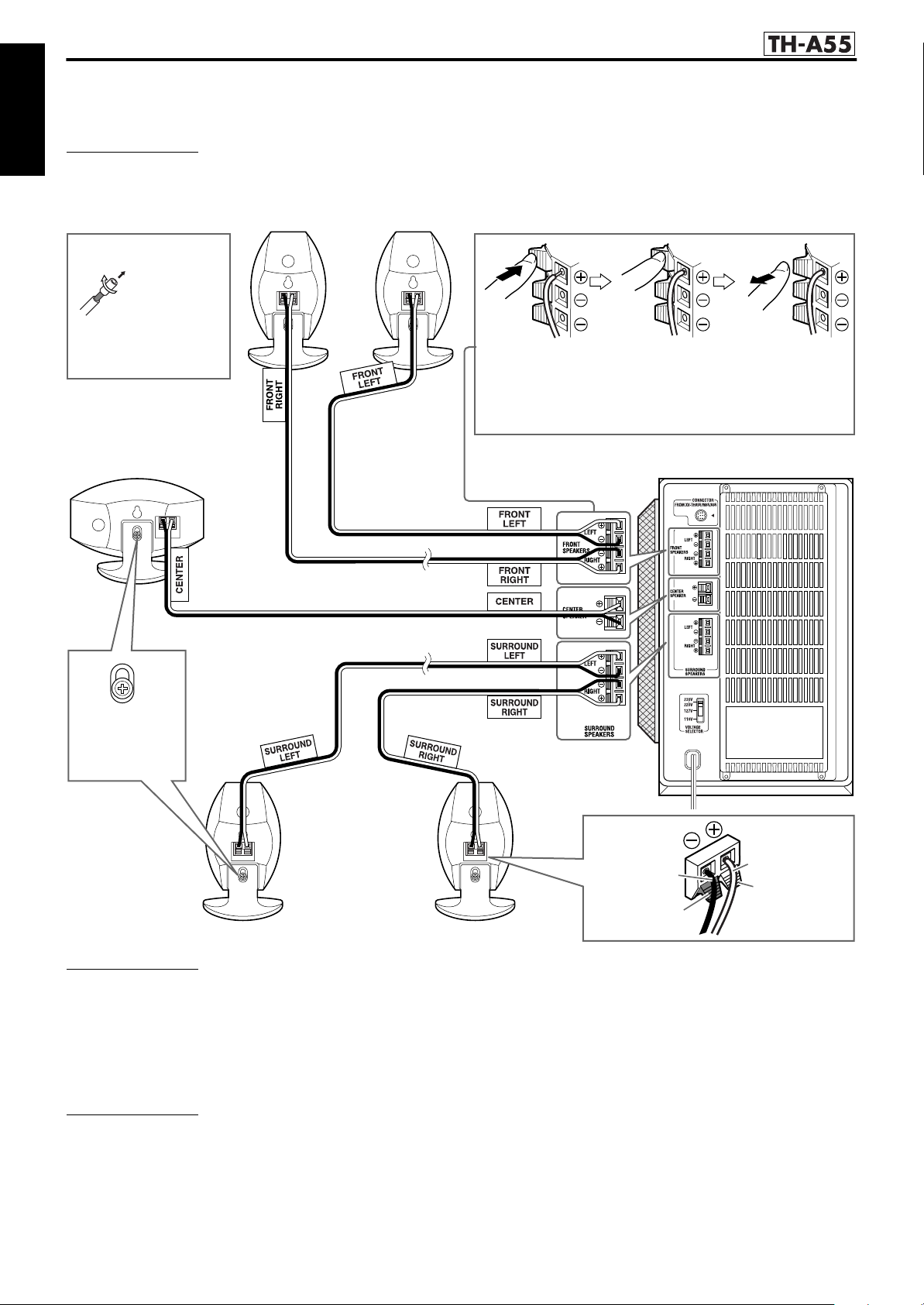
Connecting the satellite (front, center, surround) speakers (TH-A55)
Be sure to identify each speaker (SP-THA55C/SP-THA55F/SP-THA55S) and connect them to the corresponding terminals of the
powered subwoofer.
English
CAUTION
• When you connect (larger) speakers other than the supplied ones, only use speakers with the same speaker impedance (SPEAKER IMPEDANCE)
as indicated by the speaker terminals on the rear of the powered subwoofer.
• DO NOT connect more than one speaker to one speaker terminal.
Front speakers (SP-THA55F)
Before connecting the
speaker cords;
Twist and pull the
insulation coat off and
remove.
Center speaker
(SP-THA55C)
Press and hold
the clamp.
• Connect the white cords to the red (ª) terminals and black
cords to the black (·) terminals.
Insert the bare end of the
speaker cord into the
terminal.
This page is for
Release the
clamp.
Tilt adjustment
screw
Powered subwoofer
Surround speakers
(SP-THA55S)
CAUTION
When installing the satellite speakers on the wall (TH-A55 only);
• Be sure to have them installed on the wall by a qualified personnel.
DO NOT install the satellite speakers on the wall by yourself to avoid unexpected damage from their falling off the wall due to incorrect installation
or weakness in wall structure.
• Care must be taken in selecting a location for speaker installation on a wall. Injury to personnel or damage to equipment may result if the speakers
installed interfere with daily activities.
• Before installing the satellite speakers on the wall, be sure to detach the speaker stands equipped with the satellite speakers by removing the tilt
adjustment screws.
NOTE
• You can attach the satellite speakers to the separately sold TV stand instead of the stands attached to them at your purchase. For assembling the TV
stand and speakers, be sure to use the screws supplied with the TV stand. Using the screws attached to the speakers may damage the speakers. For
details, refer to the instructions manual supplied with the TV stand.
• You can tilt the satellite speakers and center speaker. Loosen the tilt adjustment screw, adjust the angle, then tighten the screw.
Black
Black
White
Red
13
Page 17
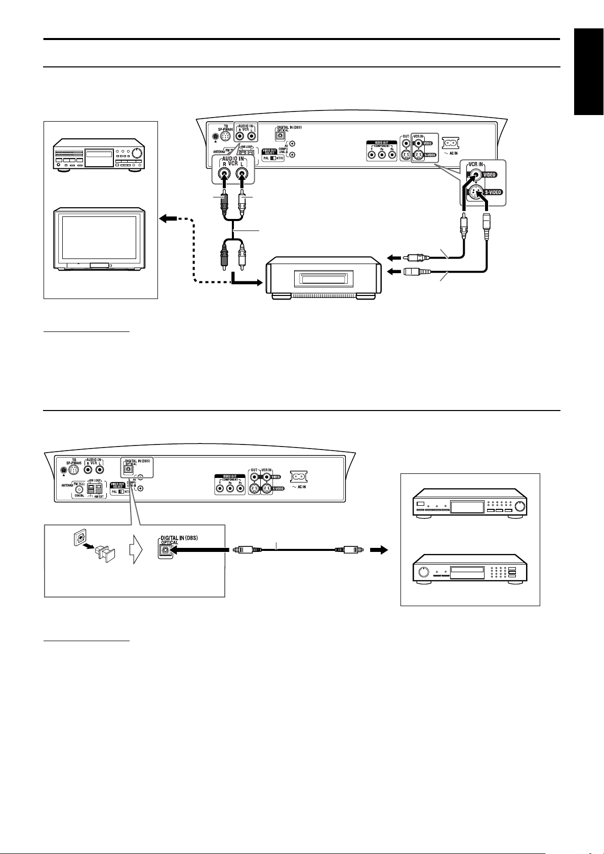
Getting started
Connecting to an analog component
You can enjoy the sound of an analog component such as a VCR, TV, or Cassette recorder with this system. Use RCA pin plug cords (not
supplied) for connection.
Center unit
English
Cassette recorder
Red
White
RCA pin plug cord
(not supplied)
A To composite video output
B To S-video output
C To audio output
Composite video cord
(not supplied)
A
or
TV
C
VCR
NOTE
• The signals input to the VIDEO jack of the VCR IN jacks will be output only from the VIDEO jack of the VIDEO OUT jacks, not from the S-VIDEO
jack of the VIDEO OUT jacks.
• If you connect a sound-enhancing device such as a graphic equalizer between the source components and this system, the sound output through this
system may be distorted.
B
S-video cord (not supplied)
Connecting to a digital component
You can enjoy the sound of a digital component such as a DBS (Direct Broadcast Satellite) tuner or MD recorder with this system. Use digital
optical cord (not supplied) for connection.
Center unit
MD recorder
Digital optical cord (not supplied)
To digital optical output
Before connecting a digital optical cord,
unplug the protective plug.
NOTE
When playing a video component such as a DBS tuner;
• To listen to the sound, select “DBS” as the source to play. (Apg. 20)
• To see the picture, connect the video output jack of the component to the video input jack of the TV directly, and select the correct input mode on the
TV.
DBS tuner
14
Page 18
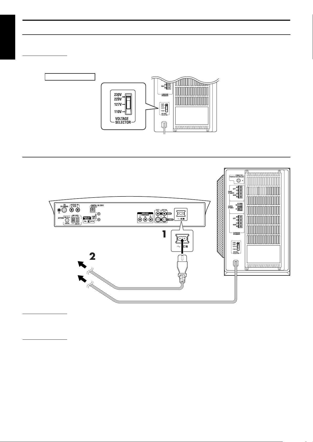
Getting started
Setting the VOLTAGE SELECTOR switch
To avoid damaging the powered subwoofer, set the VOLTAGE SELECTOR switch on the rear panel to the correct voltage for your area.
When you change the position of the VOLTAGE SELECTOR switch, use a tool such as a slotted screwdriver, etc.
English
CAUTION
DO NOT plug the power cord of the powered subwoofer before setting the VOLTAGE SELECTOR switch to the correct
voltage.
Except for Hong Kong
Powered subwoofer
Connecting the power cord
Make sure that all connections have been completed, before plugging in the power cords of the center unit and powered subwoofer.
1 Firmly insert the supplied power cord into the
unit.
Ó
AC IN socket on the rear of the center
2 Plug both power cords into AC outlets.
Center unit
Plug into AC outlets.
Power cord (supplied)
Power cord
CAUTION
• Disconnect the power cord before cleaning or moving the system.
• Do not touch the power cord with wet hands.
• Do not pull on the power cord to unplug the cord. When unplugging the cord, always grasp and pull the plug so as not to damage the cord.
NOTE
• Keep power cords away from other connected cords. The power cords may cause noise or screen interference.
• Preset settings, such as preset stations and surround mode adjustment, may be erased in a few days in the following cases;
If you unplug the power cord of the center unit.
•
If a power failure occurs.
•
• The speakers will not produce any sound if the power cord of the powered subwoofer is removed from the AC outlet while the center unit is turned on.
In this case, press
AUD IO
F
• If the AC outlets do not match the AC plugs, use the supplied AC plug adaptors (not supplied for Hong Kong).
or
F
F
again.
on the remote control or
AUD IO
on the center unit to turn the power off, plug in the powered subwoofer, then press
F
Powered subwoofer
15
Page 19
Getting started
Remote sensor
Using the remote control
The remote control makes it easy to use many of the system
functions from a distance of up to 7 m away.
• You can also use the remote control supplied for this system to
operate other manufacturers’ TVs (A pg. 17), VCRs (A pg. 18)
and DBS tuners/CATV converters (A pg. 17).
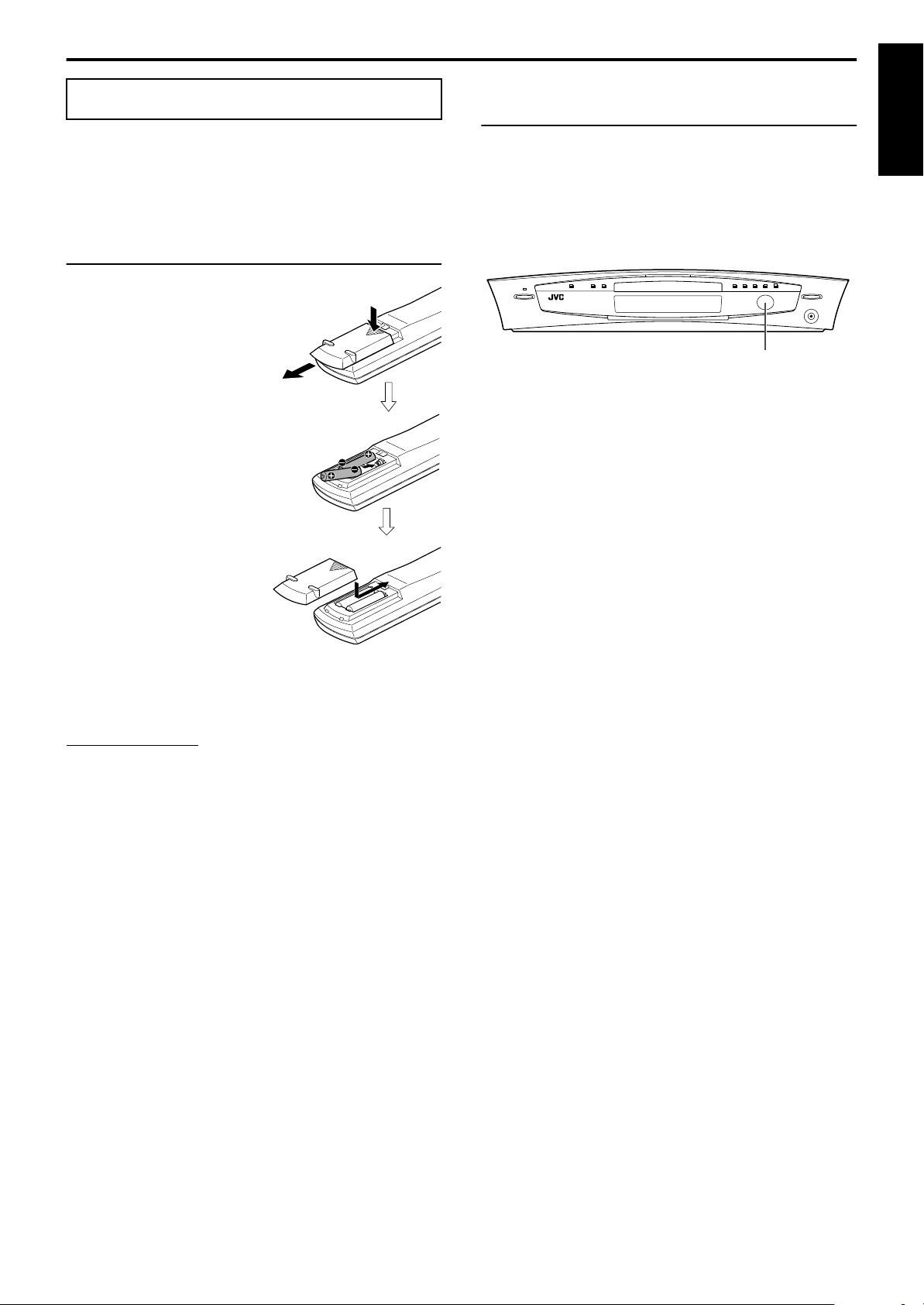
Putting batteries in the remote control
Before using the remote control, first put in the 2 supplied batteries.
1 Remove the battery
cover on the back of
the remote control.
2 Insert the batteries.
• Make sure to match polarity: (+) to
(+) and (–) to (–).
Operating the system from the remote
control
Aim the remote control directly at the remote sensor on the center
unit.
• To control other components, aim the remote control directly at
the remote sensor on each component. Refer also to their
instruction manuals.
• To operate the remote control properly, do not hide the remote
sensor by placing any obstructions in front of it.
English
3 Replace the cover.
If the range or effectiveness of the remote control decreases,
replace the batteries. Use two R6P (SUM-3)/AA (15F) type drycell batteries.
CAUTION
• Follow these precautions to avoid leaking or cracking batteries;
Use the correct type of batteries. Batteries that look similar may
•
differ in voltage.
Always replace both batteries at the same time.
•
Do not expose batteries to heat or flame.
•
16
Page 20
Getting started
NOTE
IMPORTANT
English
(play button)
4 Press number buttons (1-9, 0) to enter
the manufacturer’s code (2 digits).
Examples:
For a Hitachi TV: Press 1, then 0.
For a Toshiba TV: Press 0, then 8.
Manufacturer Code Manufacturer Code
JVC 01 Samsung 12
Hitachi 10 Sanyo 13
Magnavox 02 Sharp 06
Mitsubishi 03 Sony 07
Panasonic 04, 11 Toshiba 08
RCA 05 Zenith 09
Number buttons
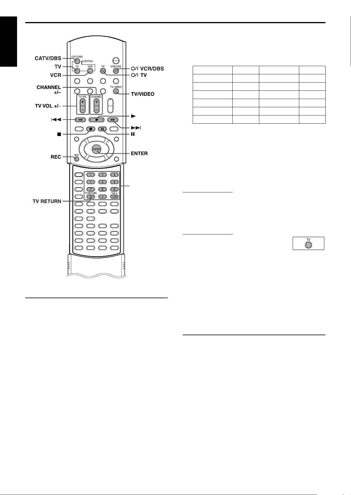
For TV operations
You can operate your TV using the remote control supplied with
this system.
• Refer also to the instruction manuals supplied with your TV.
7
To set the manufacturer’s code
You can operate a JVC TV without setting the remote control
signal.
1 Press TV.
2 Press and hold
Keep the button pressed until step 4 is finished.
F
TV.
3 Press ENTER.
5 Release
F
TV.
6 Try operating your TV by pressing
F
TV.
When your TV turns on or off, you have entered the correct
code.
If there is more than one code listed for corresponding brand,
try each one until you enter the correct one.
• Manufacturers’ codes are subject to change without notice. If they are
changed, this remote control cannot operate the equipment.
• Set the codes again after replacing the batteries of the remote control.
7
Operation
Before using the remote control to operate a TV;
• Press TV.
The following buttons are available:
TV
F
: Turns TV on and off.
TV VOL +/–
TV/VIDEO
CHANNEL +/–
1-10, 0, +10 (100+)
TV RETURN
: Adjusts the volume.
: Selects the input mode (either TV or
VIDEO).
: Changes the channels.
: Selects the channel.
: Alternates between the previously selected
channel and the current channel.
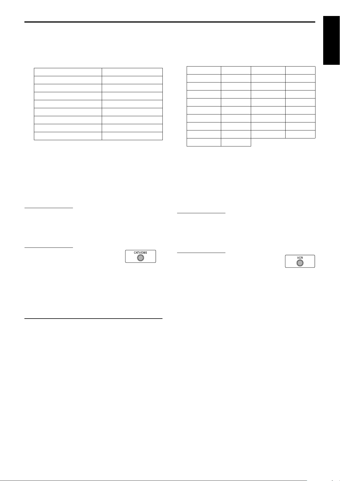
For DBS tuner or CATV converter
operations
You can operate your DBS tuner or CATV converter using the
remote control supplied with this system.
• Refer also to the instruction manuals supplied with your DBS
tuner or CATV converter.
7
To set the manufacturer’s code
1 Press CATV/DBS.
17
2 Press and hold
Keep the button pressed until step 4 is finished.
F
VCR/DBS.
3 Press ENTER.
Page 21
Getting started
NOTE
IMPORTANT
4 Press number buttons (1-9, 0) to enter
the manufacturer’s code (2 digits).
Examples:
For a GI Jerrold product:Press 0, then 1.
For a Sony product: Press 2, then 0.
Manufacturer Code
Echostar 21
GI Jerrold 01, 02, 03, 04, 05, 06, 07, 08
Hamin/Regal 15, 16, 17, 18
Pioneer 13, 14
RCA 19
Scientific Atlanta 09, 10
Sony 20
Zenith 11, 12
5 Release
F
VCR/DBS.
6 Try operating your DBS tuner or CATV
converter by pressing
When your DBS tuner or CATV converter turns on or off, you
have entered the correct code.
If there is more than one code listed for your brand, try each
one until you enter the correct one.
NOTE
• Manufacturers’ codes are subject to change without notice. If they are
changed, this remote control cannot operate the equipment.
• Set the codes again after replacing the batteries of the remote control.
7
Operation
IMPORTANT
Before using the remote control to operate a
DBS tuner or CATV converter;
CATV/DBS
• Press
The following buttons are available:
VCR/DBS
F
CHANNEL +/–
1-10, 0, +10 (100+)
.
: Turns DBS tuner or CATV converter on and
off.
: Changes the channels.
: Selects the channel.
For VCR operations
You can operate your VCR using the remote control supplied with
this system.
• Refer also to the instruction manuals supplied with your VCR.
7
To set the manufacturer’s code
F
VCR/DBS.
4 Press number buttons (1-9, 0) to enter
the manufacturer’s code (2 digits).
Examples:
For a Philips VCR: Press 0, then 9.
For an NEC VCR: Press 2, then 5.
Manufacturer Code Manufacturer Code
JVC 01, 02, 03 Philips 09
Emerson 11, 26 RCA 05, 06
Fisher 29 Samsung 24
Funai 10, 14, 15, 16 Sanyo 21, 22, 23
Gold Star 12 Sharp 27, 28
Hitachi 04 Shintom 30
Mitsubishi 13 Sony 18, 19, 20
NEC 25 Zenith 08
Panasonic 07, 17
5 Release
F
VCR/DBS.
6 Try operating your VCR by pressing
F
VCR/DBS.
When your VCR turns on or off, you have entered the correct
code.
If there is more than one code listed for your brand, try each
one until you enter the correct one.
• Manufacturers’ codes are subject to change without notice. If they are
changed, this remote control cannot operate the equipment.
• Set the codes again after replacing the batteries of the remote control.
7
Operation
Before using the remote control to operate a VCR;
• Press
The following buttons are available:
F
3
7
8
¢
4
REC
CHANNEL +/–
1-10, 0
VCR
(Remote control mode selecting
button).
VCR/DBS
(play button): Starts playback.
: Stops operation.
: Pauses playback.
: Fast forwards video tape.
: Rewinds video tape.
: Press this button together with 3 (play button) to
: Turns VCR on and off.
start recording or together with 8 to pause
recording.
: Changes the TV channels on the VCR.
: Selects the channel. (for the JVC’s VCR only)
English
1 Press VCR (Remote control mode
2 Press and hold
3 Press ENTER.
selecting button).
F
VCR/DBS.
Keep the button pressed until step 4 is finished.
18
Page 22
Basic operations
NOTE
Message area
This section mainly explains operations commonly used when you
enjoy this system.
• Turn on your TV and select the correct input mode on the TV.
English
Source
selecting
buttons
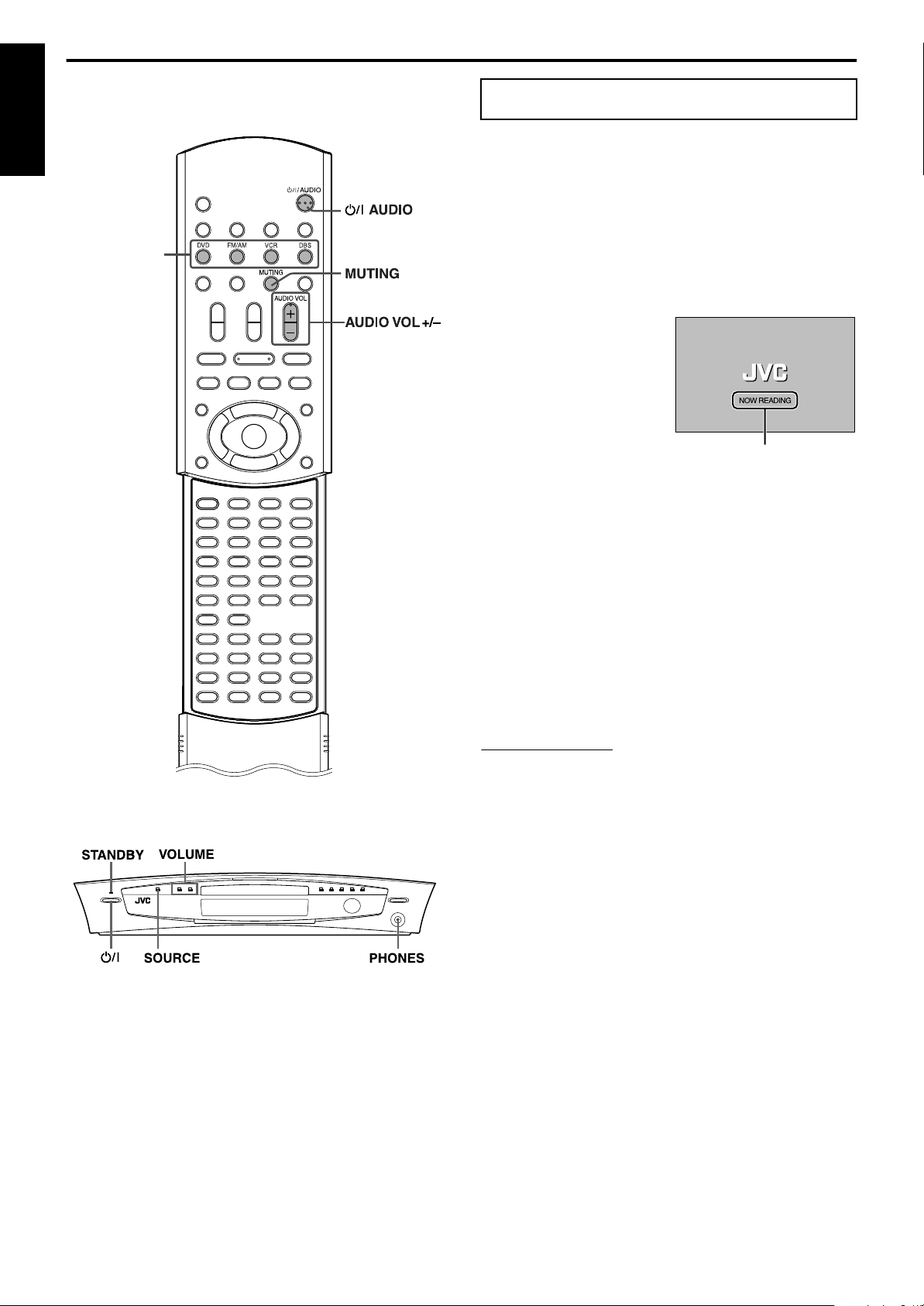
Turning the system on/off
7
To turn the power on
On the remote control:
Press
On the center unit:
Press F.
The STANDBY lamp goes off.
When DVD is selected as the source (A pg. 20), the opening
screen* appears on the TV screen.
* Opening screen
The following messages may
appear in the message area
depending on the status of this
system.
• “OPEN”/“CLOSE”:
• “NOW READING”:
• “REGION CODE ERROR!”:
•“NO DISC”:
F
AUDIO.
Appears when opening or
closing the disc tray.
Appears when the system is
reading the disc information.
Appears when the Region Code of the DVD does not match the
code the center unit supports. The DVD cannot be played back.
Appears when no disc is loaded to the disc tray.
7
To turn the power off
On the remote control:
Press
On the center unit:
F
AUDIO again.
Press F again.
The STANDBY lamp lights.
• The power supply to the subwoofer is linked to the center unit. The
POWER ON lamp on the subwoofer lights green when the power is
turned on.
• A small amount of the power is consumed even when the power is
turned off (center unit only). This is called standby mode and the
STANDBY lamp lights in this mode. Unplug the power cord from the
AC outlet to turn the power off completely.
• You can also turn on the system by pressing the following buttons;
The center unit’s
•
One of the source selecting buttons on the remote control
•
on the remote control (except after pressing
•
3
center unit
0
) or on the
FM/AM
19
Page 23
Basic operations
CAUTION
Selecting the source to
play
On the remote control:
Press one of the source selecting buttons
(DVD, FM/AM, VCR or DBS).
DVD
: To play back a disc (DVD, Video CD etc.). (A pg. 23, 25)
FM/AM
: To tune in an FM or AM station. (A pg. 27)
Each time you press the button, the band alternates
between FM and AM.
VCR
: To select the source from a component connected to the
VCR IN jacks and AUDIO IN (VCR) jacks. (A pg. 14)
DBS
: To select the source from a component connected to the
DIGITAL IN (DBS) jack. (A pg. 14)
On the center unit:
Press SOURCE repeatedly until the source
name you want appears on the display
window.
Each time you press the button, the source changes as follows;
DVD ] AM ] FM ] VCR ] DBS ] (back to the
]
beginning)
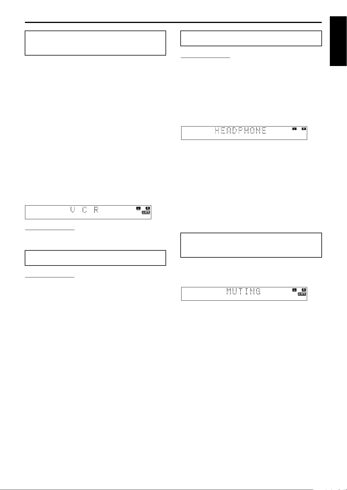
The selected source name appears on the display window.
Example:When “VCR” is selected.
NOTE
• When AM, FM or DBS is selected as the source, this system does not
output video signals.
Adjusting the volume
CAUTION
• Always set the volume to minimum level before starting any source.
If the volume is set at its high level, the sudden blast of sound could
permanently damage your hearing and/or blow out the speakers.
You can adjust the volume level within the range from “0”
(minimum) to “60” (maximum).
On the remote control:
Press AUDIO VOL + or –.
• Press + to increase volume.
• Press – to decrease volume.
Listening with headphones
Be sure to turn down the volume;
• Before connecting or putting on headphones as high volume may
damage both the headphones and your hearing.
• Before disconnecting headphones as high volume may be suddenly
output from the speakers.
Connect a pair of headphones to the PHONES jack on the center
unit. This cancels the surround mode (A pg. 31) currently selected,
deactivates the speakers, turns the subwoofer’s power off, and
activates the headphone mode. “HEADPHONE” appears on the
display window.
• Disconnecting a pair of headphones from the PHONES jack
cancels the headphone mode and activates the speakers at the
previously selected surround mode.
Headphone mode
When using the headphones, the following signals are output
regardless of your speaker setting;
• For 2 channel sources, the front left and right channel signals are
output directly from the left and right headphones.
• For multi-channel sources, the front left and right, center and
surround channel signals are down-mixed and then output from
the headphones.
You can enjoy the down-mixed multi-channel sound source using
the headphones.
Turning off the sound
temporarily
On the remote control:
Press MUTING.
“MUTING” appears on the display window and the sound turns off.
To restore the sound
MUTING
Press
• Pressing
also restores the sound.
again.
AUD IO VOL +/–
VOLUME +/–
(or
on the center unit)
English
On the center unit:
Press VOLUME + or –.
• Press + to increase volume.
• Press – to decrease volume.
The volume level appears on the display window.
20
Page 24
Basic operations
NOTE
NOTE
Using the Sleep Timer
English
Using the Sleep Timer, you can fall asleep while listening to music
and know the system will turn off by itself rather than play all night.
On the remote control:
Press SLEEP.
Each time you press the button, the shut-off time changes as
follows;
0min (cancelled) ] 10min (minutes) ] 20min ] 30min
]
60min ] 90min ] 120min ] 150min ] (back to the
]
beginning)
To check the remaining time until the shut-off time
SLEEP
Press
• The remaining time until the shut-off time appears on the display
window for a while.
To change the remaining time until the shut-off time
Press
• Each time you press the button, the shut-off time changes.
To cancel the Sleep Timer
Press
window.
• Turning off the power also cancels the Sleep Timer.
• When DVD is selected as the source to play, the system can also turn
off automatically if playback is not restarted within the length of time
you have specified (Auto Standby function). (Apg. 51)
• When both the Sleep Timer and Auto Standby function are activated,
if the shut-off time set by the Auto Standby function comes earlier
than the one set by the Sleep Timer, the Auto Standby function
controls shut-off time.
once.
SLEEP
repeatedly.
SLEEP
repeatedly until “0min” appears on the display
Adjusting the brightness
You can dim the indications on the display window and the
illumination lamp level on the center unit.
On the remote control:
Press DIMMER.
Each time you press the button, the brightness level changes as
follows;
OFF ] DIMMER1 ] DIMMER2 ] (back to the
]
beginning)
• OFF: Returns to the normal level.
• DIMMER1: Dims the display window and the illumination
lamp.
• DIMMER2: Dims the display window more than DIMMER1
and turns off the illumination lamp.
Adjusting the output level
of the subwoofer
You can adjust the output level within the range from –10 to +10.
On the remote control:
Press S.WFR +/–.
• You can also make adjustments using the choice menu shown on the
TV screen. (Apg. 50)
• The adjustments on a source take effect for the other sources.
21
Page 25
Basic operations
NOTE
Adjusting the bass/treble
sound
You can adjust each enhancement level from the front speakers
within the range from –10 to +10.
On the remote control:
Press BASS +/– for bass sound.
Press TREBLE +/– for treble sound.
NOTE
• You can also make adjustments using the choice menu shown on the
TV screen. (Apg. 49)
• The adjustments on a source take effect for the other sources.
• You can adjust bass/treble enhancement level only for front left/right
channel. However, the supplied speakers cannot add the effective
change to the bass sound because of their cutoff frequency even if the
bass sound adjustment is made. (Apg. 50)
To change the bass enhancement level more efficiently, adjust the
output level of the subwoofer. (A “Adjusting the output level of the
subwoofer”)
(When you change the front speakers to the larger ones and select
“LARGE” for the front speakers in the SIZE sub-menu (Apg. 50),
the effective adjustment of bass sound is also possible by pressing
BASS +/–
.)
Changing the decode
mode
When you play a disc (or software) encoded with Dolby Digital or
DTS Digital Surround, the following symptoms may occur;
• Sound does not come out at the beginning of playback.
• Noise comes out while searching for or skipping chapters or
tracks.
In these cases, change the decode mode to “DOLBY D” (for Dolby
Digital) or “DTS” (for DTS Digital Surround).
7
When DVD or DBS is selected as the source
On the remote control:
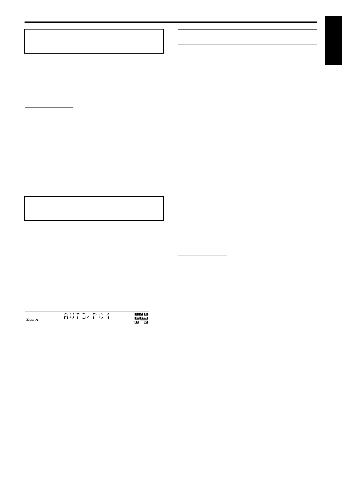
Press DECODE to select the decode mode.
The current decode mode appears on the display window.
Example:When “AUTO/PCM” is selected.
Changing the scan mode
This system supports the progressive scan system (525p*) as well
as the conventional interlaced scan system (525i*).
If your TV equipped with component jacks supports the
progressive video input, you can enjoy a high quality picture by
setting the progressive scan mode to active.
• Refer also to the instruction manuals supplied with your TV.
• If your TV equipped with component jacks does not support the
progressive video input, do not change the scan mode to the
progressive scan mode.
* 525p and 525i indicate the number of scanning lines and
scanning format of an image signal.
525p indicates 525 scanning lines with progressive format.
•
525i indicates 525 scanning lines with interlaced format.
•
7
When DVD is selected as the source
On the remote control:
1 Press DVD.
2 Press and hold PROGRESSIVE for
3 seconds.
Each time you perform this operation, the scan mode changes
as follows;
INTERLACE O PROGRESSIVE
• INTERLACE: Select this if your TV equipped with
component jacks supports the interlaced
video input only.
• PROGRESSIVE:Select this if your TV equipped with
component jacks supports the progressive
video input.
When “PROGRESSIVE” is selected, the PROGRESSIVE
indicator lights.
• When “PAL” is selected on the
(Apg. 8), the scan mode is fixed to “INTERLACE”. So the scan
mode cannot be changed.
• There are some progressive TVs and High-Definition TVs that are not
fully compatible with this system, resulting in an unnatural picture
when playing back a DVD in the progressive scan mode. In such a
case, change the scan mode to “INTERLACE”.
To check the compatibility of your TV, contact your local JVC
customer service center.
• All JVC progressive TVs and High-Definition TVs are fully
compatible with this system.
VIDEO OUT SELECT
switch
English
Each time you press the button, the decode mode changes as
follows;
AUTO/PCM ] DOLBY D ] DTS ] (back to the
]
beginning)
• AUTO/PCM: Normally select this. The system automatically
detects the incoming signals.
• DOLBY D: Select this if the symptoms above occur when
playing a disc (or software) encoded with Dolby
Digital.
• DTS: Select this if the symptoms above occur when
playing a disc (or software) encoded with DTS
Digital Surround.
NOTE
• When “DOLBY D” or “DTS” is selected, if a signal encoded with
another digital format comes in, you cannot listen to the sound. (The
DIGITAL or C indicator flashes.)
G
• Changing the source returns the decode mode to “AUTO/PCM”
automatically.
22
Page 26
Playback
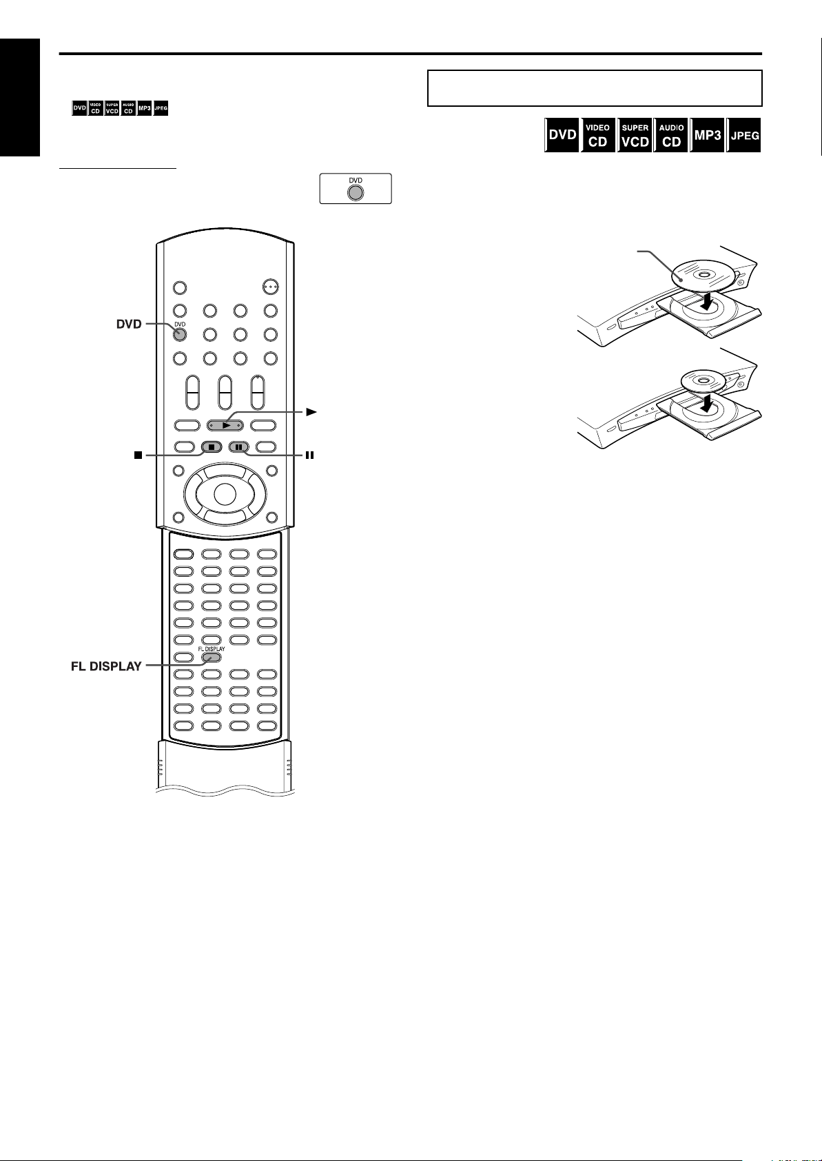
With the label side up
When placing an 8 cm disc
This section explains basic operations of DVD player.
For more details about DVD player operations, see pages 33 to 45.
• shows the types of discs the operation is
available for.
English
• Turn on your TV and select the correct input mode on the TV.
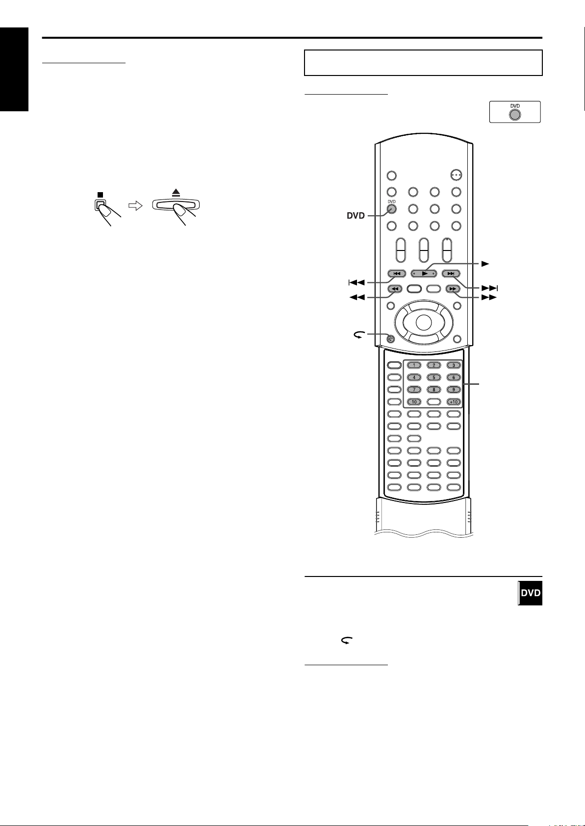
IMPORTANT
Before using the remote control for the following
operation;
DVD
• Press
.
(play button)
Basic playback
7
To load a disc
1 Press
0
on the center unit to open the
disc tray.
The system turns on and the disc tray comes out.
2 Place a disc on the disc tray.
7
To start playback
3 Press
The system starts playback after closing the disc tray.
You can use the same buttons on the center unit for operations
unless otherwise noted.
When loading an MP3 disc
The MP3 control display (A pg. 36) appears on the TV screen and
playback starts from the first track in the first group after pressing
3
(play button) in step 3. When all tracks in a group have been
played, the system starts playback of tracks in the next group.
When loading a JPEG disc
The slide-show* playback starts from the first file in the first group
after pressing 3 (play button) in step 3. When stopping playback of
a JPEG disc, the JPEG control display (A pg. 37) appears on the
TV screen.
* Slide-show
Each file (still picture) is shown on the TV screen for about 3
seconds, then changed to the next file one after another
automatically. When all files in a group have been played, the
system starts playback of files in the next group.
7
To pause playback
3
(play button).
Press 8.
To return to normal playback, press 3 (play button).
7
To stop playback
Press 7.
23
To remove a disc
Press 0 on the center unit.
Page 27
Playback
NOTE
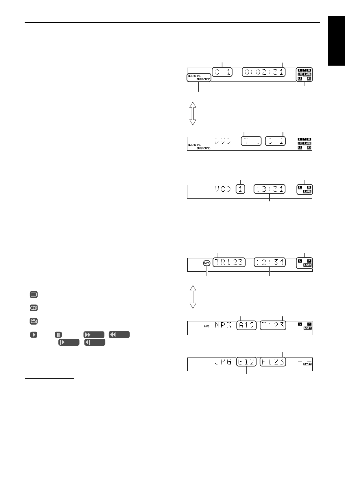
Signal and speaker indicators
Chapter number
Elapsed playing time
(hour:minute:second)
Surround mode and digital signal format
Title number
Each time
FL DISPLAY
is pressed, the indications
alternate between those shown above and below.
Chapter number
Track number
Elapsed playing time (minute:second)
Signal and speaker
indicators
Track number
Elapsed playing time (minute:second)
(during playback only)
Group number Track number
Each time
FL DISPLAY
is pressed, the indications
alternate between those shown above and below.
Signal and speaker
indicators
MP3 indicator
Group number
File number
Continued on next page
NOTE
• You can check playback information on the display window and the
TV screen. (Apg. 33)
• Some tracks on an MP3 disc may be skipped or may not be played
back normally.
• When you play back a JPEG disc, press buttons after the whole
picture appears on the TV screen. The system cannot accept
operations even though you press buttons while showing a picture.
• Some files on a JPEG disc may be played back distortedly.
• If a black screen continuously appears in the slide-show playback, the
file currently being played may be a non-baseline JPEG file. In this
case, select a playable file (a baseline JPEG file). For example, press
or
7
take a long time to select another file.
7
Resume Playback (DVD/Video CD/SVCD only)
When Resume Playback is set to “ON” (A pg. 51) and you stop
playback by the following operations, the position where playback
has been stopped is stored. (The RESUME indicator lights.)
• Turning off the power (A pg. 19)
• Pressing
• Changing the source (A pg. 20)
To start playback from the stored position
(The RESUME indicator goes off.)
• Press 3 (play button) on the remote control or the center unit.
• Select DVD as the source again if you changed the source.
to open the JPEG control display, etc. Note that it may
MENU
7
7
Playback information on the display window
DVD
Example:When a DVD encoded with Dolby Digital 5.1ch is played
Video CD/SVCD/Audio CD
Example:When a Video CD is played back
English
To clear the stored position
Press 7 again or open the disc tray.
• When the stored position has been cleared, playback starts from
the beginning of the disc.
7
To prevent screen burn-out with the screen saver
A TV screen may burn out if a static picture is displayed for a long
time. To prevent this, the system automatically dims the screen if a
static picture is displayed for over 5 minutes (the screen saver
function).
• Pressing any button will cancel the screen saver function.
• If you do not want to use the screen saver function, see page 49.
7
On-screen guide icons
During DVD playback, the following guide icons may appear for a
while on the TV screen;
• : appears at the beginning of a scene containing multi-
subtitle languages.
• : appears at the beginning of a scene containing multi-audio
languages.
• : appears at the beginning of a scene containing multi-angle
views.
• (Play), (Pause), / (Fast forward/
fast-reverse), / (Slow-motion forward/
reverse): appears when you perform each operation.
• If “B” appears on the TV screen when pressing a button, the disc
cannot accept an operation you have tried to do or information
required for that operation is not recorded to the disc.
NOTE
• In some cases, without showing “B”, operations will not be accepted.
• If you do not want the on-screen guide icons to appear, see page 51.
• When a Video CD or SVCD with PBC function is played, the elapsed
playing time does not appear, but “PBC” appears.
MP3 disc
JPEG disc
24
Page 28
Playback
IMPORTANT
NOTE
Number
buttons
(play button)
NOTE
• You can change the time information mode. (Apg. 34)
• You can also check the playback information on the TV screen.
English
(Apg. 33)
7
Tray lock
You can lock the tray and prohibit the unwanted disc ejection by
children.
On the center unit ONLY:
While the system is turned off
Press and hold 7, then press 0.
• The system turns on and “LOCKED” appears on the display
window.
• If you try to eject a disc, “LOCKED” appears and indicates that
the tray is locked.
To unlock the tray
When the system is turned off, press and hold 7, then press 0.
• The system turns on and “UNLOCKED” appears on the display
window.
Playback features
Before using the remote control for the following
operation;
• Press
DVD
.
25
One Touch Replay
You can move back the playback position by 10 seconds
from the current position.
7
During playback
On the remote control:
Press .
• This function works between chapters in the same title.
• This function may not work for some DVDs.
Page 29
Playback
NOTE
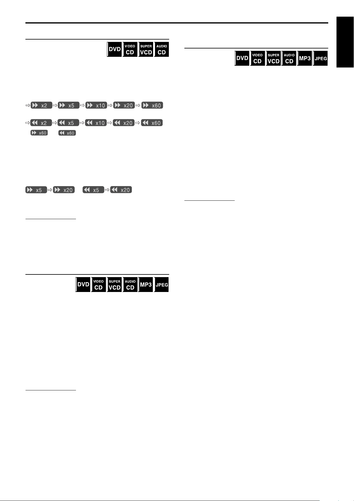
Fast-forward/fast-reverse search
You can search for a particular point
while playing a disc.
7
During playback
On the remote control:
Press
Each time you press the button, the search speed changes as
follows;
Forward:
Reverse:
* and are only available for DVD.
To return to normal speed playback
Press 3 (play button).
On the remote control and the center unit:
Press and hold
Continuously pressing ¢/4 increases the fast-forward/reverse
search speed as follows;
¡/1
.
¢/4
*
*
.
/
To return to normal speed playback
Release the button.
NOTE
• When a DVD, Video CD or SVCD is played back, no sound comes
out during fast-forward/reverse search.
• When an Audio CD is played back, sound is intermittent and low
during fast-forward/reverse search.
• This function may not work for some DVDs.
Locating a desired selection using number
buttons
You can locate the
desired title, chapter,
track or file by
selecting its number.
7
For DVD (title, chapter):
While stopped (the title number is selected.)
During playback (the chapter number is selected.)
For Video CD/SVCD (track): During playback without PBC
function
For Audio CD/MP3/JPEG (track/file): During playback or while
stopped
On the remote control:
Press number buttons (1-10, +10) to select
the desired title, chapter or track number.
Examples:
To select 3: Press 3.
To select 14: Press
To select 24: Press
To select 40: Press
The specified title, chapter, track or file number appears on the
display window and playback begins from that location.
• While playing a DVD, if a menu is shown on the TV screen, number
buttons may be used for selecting an item in the menu. (Apg. 34)
• While playing a Video CD or SVCD with the PBC function, if a menu
is shown on the TV screen, number buttons are used for selecting an
item in the menu. (Apg. 35)
+10
, then 4.
+10
twice, then 4.
+10
three times, then 10.
English
Locating the beginning of a desired
selection
You can locate the
beginning of a
chapter, track or file.
7
For DVD (chapter): During playback
For Video CD/SVCD (track): During playback without PBC
function
For Audio CD/MP3/JPEG (track/file): During playback or while
stopped
To skip chapters, tracks or files forward
Press
To skip to the beginning of the current chapter, track or
file
Press
To skip chapters, tracks or files backward
Press
NOTE
• This function may not work for some DVDs.
• When playing a Video CD or SVCD with the PBC function,
• When playing back an MP3/JPEG disc, you can make operations
¢
as many times as required.
4
once.
4
as many times as required.
may be used for the operations of menu-driven playback.
4
(Apg. 4, 35)
using the MP3/JPEG control display. (Apg. 36, 37)
¢
and
26
Page 30
Tuner operations
NOTE
NOTE
After a few seconds
You can browse through all the stations or use the preset function to
go immediately to a particular station.
IMPORTANT
English
Before using the remote control for the following
operation;
• Press FM/AM.
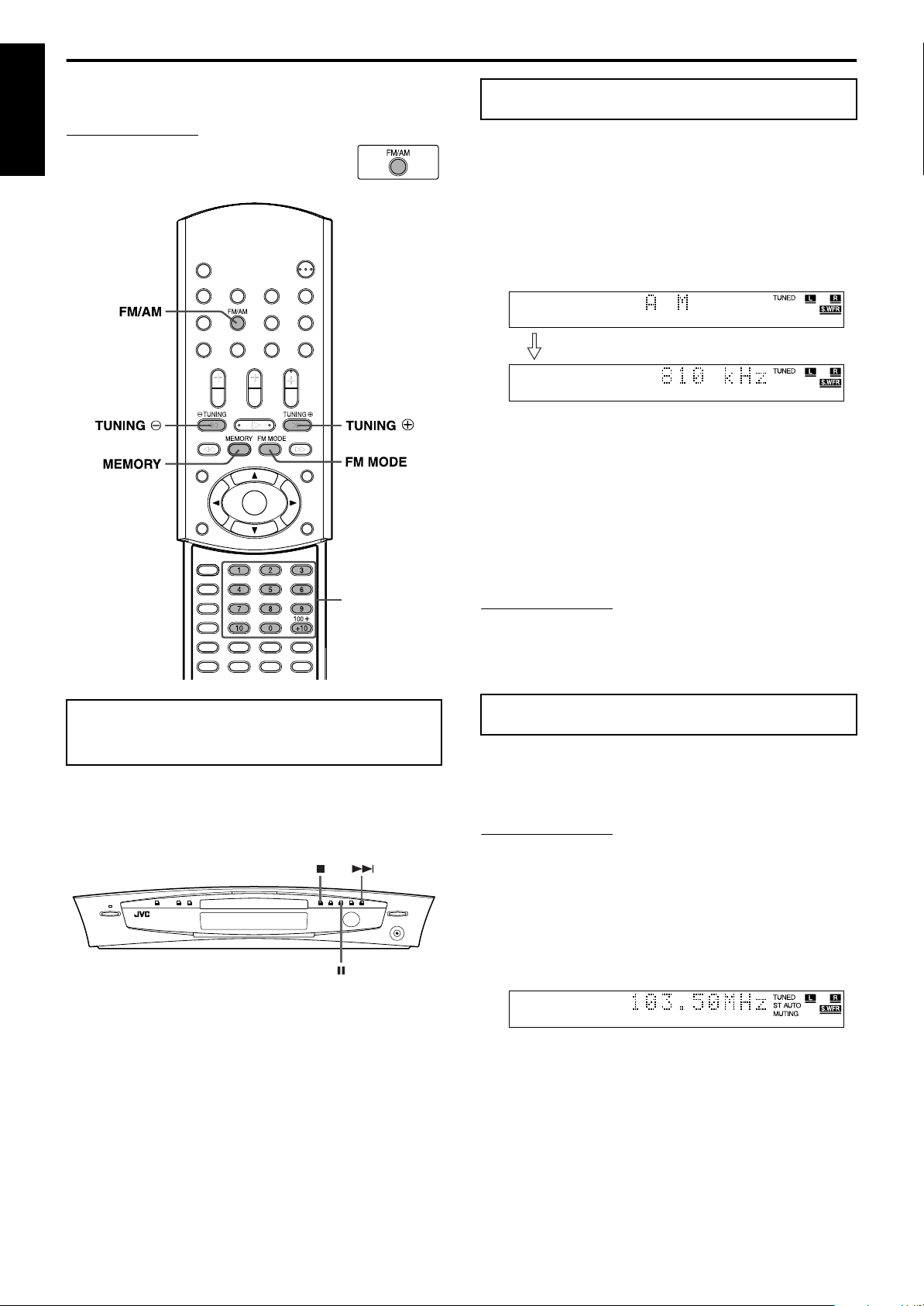
Manual tuning
On the remote control:
1 Press FM/AM repeatedly to select the
band.
Each time you press the button, the band alternates between
FM and AM.
The selected band appears on the display window, then the last
received station appears.
Example:When AM is selected
Number buttons
Setting the AM tuner
interval spacing
Some countries space AM stations 9 kHz apart, and other countries
use 10 kHz spacing.
• 9 kHz interval spacing is the initial setting.
On the center unit ONLY:
2 Press TUNING
or TUNING·
ª
repeatedly until you find the frequency
you want.
When you hold down the button until the system starts
searching for stations and then release it, the system stops
searching automatically when a station of sufficient signal
strength is tuned in to.
• TUNING ª: Increases frequency.
• TUNING ·: Decreases frequency.
• When a station of sufficient signal strength is tuned in, the TUNED
indicator lights on the display window.
• When an FM stereo program is received, the ST indicator lights on the
display window.
Preset tuning
Once a station is assigned to a channel number, the station can be
quickly tuned in. You can preset 30 FM and 15 AM stations.
To preset the stations
7
Before you start operation;
• There is a time limit when doing the following steps. If the setting is
cancelled before you finish, start from step 2 again.
7 When AM is selected as the source
To select the 10 kHz interval
Press and hold 8, then press ¢. “10k STEP” appears on the
display window. Now the 10 kHz interval is selected.
To select the 9 kHz interval
Press and hold 7, then press ¢. “9k STEP” appears on the
display window. Now the 9 kHz interval is selected.
27
1 Tune in the station you want to preset.
• For the detailed procedure, see “Manual tuning”.
• If you want to store the FM reception mode for an FM
station, select the reception mode you want. See “Selecting
the FM reception mode” (A pg. 28).
Page 31

Tuner operations
2 Press MEMORY.
The channel number position starts flashing on the display
window for about 5 seconds.
While the channel number position is flashing:
3 Press number button(s) (1-10, +10) to
select a channel number.
The channel number and the CH indicator start flashing.
Examples:
For channel number 3: Press 3.
For channel number 14: Press +10, then 4.
(For FM stations only)
For channel number 24: Press +10 twice, then 4.
For channel number 30: Press +10 twice, then 10.
While the selected number is flashing:
4 Press MEMORY again.
The selected number stops flashing.
The station is assigned to the selected preset number.
Selecting the FM
reception mode
When the stereo FM program currently tuned in is noisy, you can
change the FM reception mode to improve the reception.
• You can store the FM reception mode for each preset station. See
“Preset tuning” (A pg. 27).
7 While listening to an FM station
On the remote control:
Press FM MODE.
The FM reception mode appears on the display window.
Each time you press the button, the FM reception mode alternates
between “AUTO MUTING” and “MONO”.
• AUTO MUTING:
When a program is broadcast in stereo, you will hear stereo
sound. (The ST indicator lights on the display window.) When in
monaural, you will hear monaural sound. This mode is also
useful to suppress static noise between stations. The AUTO
MUTING indicator lights on the display window.
•MONO:
Reception will be improved although you will lose the stereo
effect. (The ST indicator goes off.) In this mode, you will hear
noise until you are tuned in to a station. (The AUTO MUTING
indicator also goes off.)
English
5 Repeat steps 1 to 4 until you store all
the stations you want.
To erase a stored preset station
Storing a new station to a used number erases the previously stored
one.
To tune in to a preset station
7
On the remote control:
1 Press FM/AM repeatedly to select the
band.
Each time you press the button, the band alternates between
FM and AM.
2 Press number button(s) (1-10, +10) to
select a preset channel number.
Examples:
For channel number 3: Press 3.
For channel number 14: Press +10, then 4.
(For FM stations only)
For channel number 24: Press +10 twice, then 4.
For channel number 30: Press +10 twice, then 10.
Reducing the noise of AM
broadcast
When listening to an AM broadcast with a lot of noise interference,
you can change the Beat Cut mode to reduce the noise.
7 While listening to an AM station
On the remote control:
Press FM MODE.
The current Beat Cut mode appears on the display window.
Each time you press the button, the Beat Cut mode alternates
between “BEAT CUT 1” and “BEAT CUT 2”.
• Choose “BEAT CUT 1” or “BEAT CUT 2” according to which
gives clearer sound.
28
Page 32

Creating realistic sound fields
You can use the following surround modes to reproduce a realistic
sound field.
• Dolby Surround
Dolby Pro Logic II
•
English
Dolby Digital
•
• DTS Digital Surround
•DSP modes
DAP modes
•
All Channel Stereo
•
7
Dolby Surround
Dolby Pro Logic II*
Dolby Pro Logic II has a newly developed multichannel playback
format to decode all 2 channel sources — stereo source and Dolby
Surround encoded source — into a 5.1 channel.
The matrix-based encoding/decoding method used by Dolby Pro
Logic II makes no limitation for the cutoff frequency of the treble
from surround channel and enables stereo surround sound
compared to conventional Dolby Pro Logic.
Dolby Pro Logic II enables to reproduce spacious sound from
original sound without adding any new sounds and tonal coloration.
Dolby Pro Logic II has two modes — Movie mode and Music
mode:
• Pro Logic II Movie (PL II MOVIE)
Suitable for reproduction of Dolby Surround encoded sources
bearing the mark . You can enjoy soundfield very
close to the one created with discrete 5.1 channel sounds.
• Pro Logic II Music (PL II MUSIC)
Suitable for reproduction of any 2 channel stereo music sources.
You can enjoy wide and deep sound by using this mode.
• When Dolby Pro Logic II is activated, the GPLII indicator
lights on the display window.
Dolby Digital*
Used to reproduce multichannel soundtracks of the software
encoded with Dolby Digital ( ).
Dolby Digital 5.1 ch (DOLBY D) encoding method (so-called
discrete multichannel digital audio format) records and digitally
compresses the front left channel, front right channel, center
channel, surround left channel, surround right channel and LFE
channel signals.
Since each channel is completely independent from the other
channel signals to avoid interference, you can obtain much better
sound quality with much stereo and surround effects.
NOTE
• Dolby Digital software can be roughly grouped into two categoriesmultichannel (up to “5.1” channel) and 2 channel software. To enjoy
surround sounds while playing Dolby Digital 2 ch software, you can
use Dolby Pro Logic II.
7
DTS Digital Surround
Used to reproduce multichannel soundtracks of the software
encoded with DTS Digital Surround ( ).
DTS Digital Surround (DTS) is another discrete multichannel
digital audio format available on CD, LD and DVD software.
Compared to Dolby Digital, audio compression ratio is relatively
low. This fact allows DTS Digital Surround format to add breadth
and depth to the reproduced sounds. As a result, DTS Digital
Surround features natural, solid and clear sound.
7
DSP modes
DAP (Digital Acoustic Processor) modes
DAP modes have been designed to create important acoustic
surround elements.
The sound heard in a live club, dance club, hall or pavilion consists
of direct sound and indirect sound — early reflections and
reflections from behind. Direct sounds reach the listener directly
without any reflection. On the other hand, indirect sounds are
delayed by the distances of the ceiling and walls (see the diagram
below).
These indirect sounds are important elements of the acoustic
surround effects. The DAP mode can reproduce a realistic sound
field by adding these indirect sounds.
The following DAP modes are provided with this system.
LIVE CLUB
DANCE CLUB
HALL
PAVILION
These DAP modes can be used to add the acoustic surround effects
while reproducing 2 channel stereo source, and can give you a real
“being there” feeling.
• When one of the DAP modes is selected, the DSP indicator lights
on the display window.
Gives the feeling of a live music club with a
low ceiling.
Gives a throbbing bass beat.
Gives clear vocal and the feeling of a concert
hall.
Gives the spacious feeling of a pavilion with a
high ceiling.
**
* Manufactured under license from Dolby Laboratories.
“Dolby”, “Pro Logic” and the double-D symbol are
trademarks of Dolby Laboratories.
29
** “DTS” and “DTS Digital Surround” are registered
trademarks of Digital Theater Systems, Inc.
Page 33

Creating realistic sound fields
Creating sound field
Reflections from behind
Early reflections
Direct sounds
All Channel Stereo
All Channel Stereo (ALL CH ST.) mode can reproduce a larger
stereo sound field using all the connected (and activated) speakers.
All Channel Stereo can be used while reproducing 2 channel stereo
source.
• When All Channel Stereo is selected, the DSP indicator lights on
the display window.
All Channel Stereo reproduction
Normal stereo sound All Channel Stereo
7
Indicators on the display window
Digital signal format indicators
LPCM: Lights when Linear PCM signal comes in.
G
DIGITAL: Lights when Dolby Digital signals come in.
C
: Lights when DTS Digital (Surround) signals come
in.
No indication: No digital signal indicator lights when analog
signals come in.
Source signal indicators, etc.
Light to indicate the incoming signals.
a
: Lights when the left channel signal comes
in.
b
: Lights when the center channel signal comes in.
c
: Lights when the right channel signal comes in.
d
: Lights when the LFE channel signal comes in.
g
: Lights when the surround left channel signal comes in.
i
: Lights when the surround right channel signal comes in.
h
: Lights when the monaural surround channel signal or 2
channel Dolby Surround signal comes in.
: Always lights.
The channel with “ ” shows that the corresponding speakers are
reproducing the channels’ sound.
If the channels’ sound decoded into 5.1 channel is reproduced, only
“ ” lights.
English
Available Surround modes for each input signal
The B marks show available surround modes.
Mode
Surround off
Signal
Dolby Digital
(Multichannel)
Dolby Digital
(2 channel)
DTS Digital
Surround
(Multichannel)
DTS Digital
Surround
(2 channel)
Analog (VCR/FM/
AM) or Linear PCM
(SURR OFF)
B —— B ——————
BBB———————
B —— — B ——— — —
B
BBB——BBB B B
* You can select these modes by pressing
Dolby Surround
PL II
MOVIE*
PL II
MUSIC*
BB———————
SURR-MODE
Dolby
Digital
. (A pg. 31)
DTS Digital
Surround
(DTS)
LIVE
CLUB*
DAP mode
DANCE
CLUB*
DSP mode
HALL* PAVILION*
ALL CH
ST.*
30
Page 34

Creating realistic sound fields
NOTE
NOTE
Using the surround mode
English
The system is set up to automatically select the optimal surround
mode for input signal from digital multichannel software.
When playing back 2 channel source, you can select the desired
surround mode manually.
On the remote control:
7
When playing back digital multichannel software
The appropriate multichannel surround mode is automatically
activated.
“DOLBY D”: When a software encoded with Dolby Digital is
“DTS”: When a software encoded with DTS Digital
In these cases, you can only turn on or off (“SURR OFF”) the
surround mode.
7
When playing back 2 channel source
You can select either mode of Dolby Pro Logic II (PL II MOVIE/
PL II MUSIC) or one of the DSP modes (LIVE CLUB/DANCE
CLUB/HALL/PAVILION/ALL CH ST.).
played back
Surround is played back
Press SURR-MODE.
The surround mode is turned on and the current surround mode
appears on the display window.
Each time you press the button, the surround mode changes as
follows;
PL II MOVIE ] PL II MUSIC ] LIVE CLUB ] DANCE
]
CLUB
beginning)
For details on each mode, see pages 29 and 30.
HALL ] PAVILION ] ALL CH ST. ] (back to the
]
To turn off the surround mode
Press SURR-ON/OFF.
Each time you press the button, the surround mode turns on and off
alternately.
SURR OFF (surround off) O current selected mode
(surround on)
• When selecting “PL II MUSIC”, “PL II MOVIE”, “DOLBY D” or
“DTS” as the surround mode, the SURROUND indicator lights.
• When selecting one of the DSP modes (“LIVE CLUB”/“DANCE
CLUB”/“HALL”/“PAVILION”/“ALL CH ST.”) as the surround
mode, the DSP indicator lights.
• For Dolby Digital 2 channel software, you can select “PL II MUSIC”
or “PL II MOVIE”.
Storing adjustments — auto memory
This system memorizes the surround mode settings for each source.
• When you turn the power off:
When turning the power on again, the memorized settings for the
current source are automatically recalled.
• When you change the source:
The memorized settings for the newly selected source are
automatically recalled.
• If the source is FM or AM, you can assign a different setting for each
band.
31
Page 35

Creating realistic sound fields
Adjusting the sound
On the remote control:
1 Press TEST.
Check if you can hear the sounds through all the speakers at
the equal level.
“TEST TONE” and the corresponding signal indicator starts
flashing on the display window, and the test tone comes out of
the speakers in the following order;
Front left speaker (a) ] Center speaker (b) ]
]
Front right speaker (
(
beginning)
Surround left speaker (g) ] (back to the
i) ]
Surround right speaker
c) ]
2 Adjust the speaker output levels (–10 to
+10).
Adjust the center speaker and surround speaker levels as much
as the sound from the front speakers. Use one of the following
buttons to adjust each speaker level.
CENTER +/–
•
SURR-L +/–
•
SURR-R +/–
•
for the center speaker
for the surround left speaker
for the surround right speaker
3 Press TEST again to stop the test tone.
English
7
For DAP modes (AAAA pg. 29) only
4 Press EFFECT to select the effect level
(1 to 5) you want.
Each time you press the button, the effect level changes as
follows;
DSP EFFECT 1 ] DSP EFFECT 2 ] DSP EFFECT 3
]
DSP EFFECT 4 ] DSP EFFECT 5 ] (back to the
]
beginning)
As the number increases, the selected mode will be more
effective. (Normally set the level to “DSP EFFECT 3”.)
NOTE
• You cannot adjust the center speaker output level for the DAP modes
and the effect level for All Channel Stereo.
• You can output the test tone in any surround mode, or even when
surround mode is not activated.
• Speaker output levels whose source signal indicator is lit can be
adjusted without pressing
• When selecting DVD as the source, you can also adjust the speaker
output levels using the choice menu. (Apg. 50)
TEST
.
32
Page 36

Advanced operations
This section explains advanced operations for disc playback using
the remote control.
• shows the types of discs an operation is
available for.
English
• Turn on your TV and select the correct input mode on the TV.
NOTE
•If “B” appears on the TV screen when pressing a button, the disc
cannot accept an operation you have tried to do or information
required for that operation is not recorded to the disc.
Using the on-screen bar
You can check disc information while the disc is loaded and you
can use some functions using the on-screen bar.
IMPORTANT
Before using the remote control for the following
operation;
• Press DVD.
Cursor
(3/2///5)
/ENTER
Contents of the on-screen bar during playback
7
DVD
Video CD
SVCD
CD
Showing the on-screen bar
Whenever a disc is loaded
7
Press ON SCREEN.
Each time you press the button, the on-screen bar changes as
follows on the TV screen.
Example:During DVD playback
(The on-screen bar disappears)
(back to the beginning)
OFF
A Shows disc type.
B Shows current transfer rate (Megabits per second).
C Shows current title (for DVD).
D Shows current chapter number (for DVD) or track number (for
other type of discs).
E Shows time information. (A pg. 34)
F Shows playback status.
: appears during playback.
/ : appears during fast forward/reverse.
/ : appears during playback in forward slow-motion/
reverse slow-motion.
: appears when paused.
: appears when stopped.
G Select this to change time information (E). (A pg. 34)
H Select this for Repeat Playback. (A pg. 44)
I Select this for time search function. (A pg. 36)
J Select this for chapter search function. (A pg. 35)
K Select this to change audio language or channel. (A pg. 39, 40)
L Select this to change subtitle language. (A pg. 39)
M Select this to change view angle. (A pg. 38)
N Select this for Program Playback. (A pg. 43)
O Select this for Random Playback. (A pg. 44)
33
Page 37

Advanced operations
NOTE
(back to the beginning)
Cursor
(3/2///5)
/ENTER
Example:
Basic operation on the on-screen bar
Example:When selecting the Repeat mode of DVD
During playback or while stopped
7
1 Press ON SCREEN twice.
The on-screen bar appears on the TV screen.
• The currently selected item shows green.
2 Press Cursor
to move H to .
3/2
3 Press ENTER.
The pop-up window appears under the selected item.
• The current setting appears.
4 Press Cursor
option.
Each time you press the button, the options change.
to select the desired
//5
Example: During DVD playback
• TIME: Elapsed playing time of current chapter/track
• REM: Remaining time of current chapter/track
• TOTAL: Elapsed time of disc
• T. REM: Remaining time of disc
To turn off the on-screen bar
Press ON SCREEN.
• While playing a Video CD, SVCD or Audio CD, the hour digit
indication does not appear.
Playing from a specified
position on a disc
You can start playing a title, chapter or track you specify. You can
also play a disc from specified time.
English
5 Press ENTER.
The setting changes and the pop-up window disappears.
To turn off the on-screen bar
Press ON SCREEN.
NOTE
• See the corresponding pages for details on each function.
Changing the time information
You can change the time information
in the on-screen bar on the TV screen
and the display window of the center
unit.
During playback or while stopped
7
1 Press ON SCREEN twice.
The on-screen bar appears on the TV screen.
2 Press Cursor
to move H to .
3/2
3 Press ENTER.
Each time you press the button, the time information changes
as follows;
Locating a desired scene from the DVD
menu
DVDs generally have their own menus which show disc
contents. These menus contain various items such as titles
of movies, names of songs or artist information, and you
can display them on the TV screen. You can locate a desired scene
by using these menus.
Whenever a DVD is loaded
7
1 Press TOP MENU or MENU.
The menu appears on the TV screen.
Normally, a DVD which contains more than one title will have
a “title” menu which lists the titles. Press TOP MENU to show
the title menu.
Some DVDs may also have a different menu which is shown
by pressing MENU.
See the instructions for each DVD regarding its particular
menu.
2 Use Cursor
desired item.
3/2///5
to select a
3 Press ENTER.
The system starts playback of the selected item.
• With some discs, you can also select items by entering the
corresponding number using number buttons.
34
Page 38

Advanced operations
NOTE
English
Cursor
(3/2///5)
/ENTER
Number buttons
Locating a desired scene using a Video
CD/SVCD menu with PBC
A Video CD or SVCD recorded with PBC has its
own menus such as a list of contained songs. You
can locate a specific scene by using these menus.
(A pg. 4)
When the menu appears on the TV screen during playback with
7
PBC function
Press number buttons (1-10, +10) to select
the number of the desired item.
The system starts playback from the selected item.
Example:
Locating a desired chapter using the onscreen bar
When playing back a DVD, you can locate the chapter
number to be played using the on-screen bar.
During playback
7
1 Press ON SCREEN twice.
The on-screen bar appears on the TV screen.
Press Cursor 3/2 to move H to .
2
3 Press ENTER.
The following pop-up window appears under the selected item.
4 Press number buttons (0-10) to enter
the desired chapter number.
Example:
To select 8: Press 8.
To select 10: Press 10.
To select 20: Press 2, then 0.
To select 37: Press 3, then 7.
To correct a misentry
Repeat step 4 until the correct number appears in the pop-up
window.
5 Press ENTER.
The system starts playback from the selected chapter.
To turn off the on-screen bar
Press ON SCREEN.
To select the number
Example:
To select 3: Press 3.
To select 11: Press +10, then 1.
To return to the menu
Press RETURN.
When “NEXT” or “PREVIOUS” is shown on the TV
screen:
• To go to the next page, press
• To return to the previous page, press
NOTE
• If you want to play a PBC-compatible Video CD/SVCD without
using the PBC function, perform any of the following:
Start playback by pressing number buttons while stopped.
•
Press ¢ repeatedly until the desired track number is displayed,
•
then start playback by pressing 3 (play button).
The track number appears on the display window instead of
“PBC”.
• To activate the PBC function when playing a PBC-compatible Video
CD/SVCD without using the PBC function, perform any of the
following:
Press
•
TOP MENU
Press 7 twice to stop playback, then press 3 (play button).
•
or
MENU
¢
.
.
.
4
•The
• You can select up to the 99th chapter.
button is not used by this function.
+10
Locating a desired title/group using
number buttons
When playing back a disc with more than
one title or one group, you can specify a
desired title or group to be played using
number buttons.
1 Press GROUP/TITLE.
“_ _” is shown in the title/group display area in the display
window.
Example: During DVD playback
35
Page 39

Advanced operations
NOTE
Total group number on
disc
Current track
Current group
Current track
number
Total track number on
disc
Total track number in
current group
Current group
number
*
Number buttons
(play button)
Cursor
(3/2///5)
/ENTER
Continued on next page
2 Use number buttons (0-10, +10) to enter
the desired title or group number.
The system starts playback from the first chapter/track/file of
the selected title/group.
Example:
To select 8: Press 8.
To select 10: Press 10.
To select 20: Press +10, then 10.
To select 25: Press +10 twice, then 5.
• Specify the number within 5 seconds after pressing
GROUP/TITLE (i.e. while the display window shows “_ _”
for the title/group number, instead of the current number).
• You can also specify the desired chapter/track/file by using
number button. (A pg. 26)
NOTE
• This function may not work for some DVDs.
Locating a desired position by specifying
the time
You can start playing at your desired
position by specifying the elapsed
playing time from the beginning of
the current title (for DVD), or from the beginning of the disc (for
Video CD/SVCD/Audio CD).
For DVD:
7
During playback
For Video CD/SVCD:
While stopped or during playback without PBC function
For Audio CD:
During playback or while stopped
Or press +10, then 0.
Or press +10 twice, then 0.
• You can also use the 10 button to enter “0”.
•The
• You can specify time in hours/minutes/seconds for DVD and in
minutes/seconds for Video CD/SVCD/Audio CD.
button is not used by this function.
+10
Using the MP3 control
display
You can search and play desired groups and tracks using the MP3
control display.
MP3 control display
7
The MP3 control display appears on the TV screen and playback
starts when a MP3 disc is selected.
English
1 Press ON SCREEN twice.
The on-screen bar appears on the TV screen.
2 Press Cursor
3 Press ENTER.
The following pop-up window appears under the selected item.
4 Use number buttons (0-9) to enter the
time.
Example:
To play back from a point 2 (hours): 34 (minutes): 08
(seconds) elapsed
TIME _ : _ _ : _ _
TIME _ : _ _ : _ _TIME 2 : 3 _ : _ _
TIME _ : _ _ : _ _TIME 2 : 3 4 : 0 _
To correct a misentry
Press Cursor
then press number buttons to enter the correct numbers.
5 Press ENTER.
The system starts playback from the specified time.
To turn off the on-screen bar
Press ON SCREEN.
to move H to .
3/2
TIME _ : _ _ : _ _TIME 2 : _ _ : _ _
Press 2 Press 3
TIME _ : _ _ : _ _TIME 2 : 3 4 : _ _
Press 4
TIME _ : _ _ : _ _TIME 2 : 3 4 : 0 8
Press 8
repeatedly until the wrong number is erased,
2
Press 0
*
Elapsed playing time of current track
Elapsed playing time is only shown during playback.
During playback
7
1 Press Cursor
to select the desired
//5
group.
2 Press Cursor
3 Press Cursor
to select the track list.
3
to select the desired
//5
track.
The playback starts from the selected track.
If you select the track while stopped
Press ENTER or
track.
(play button) to start playback of the selected
3
36
Page 40

Advanced operations
NOTE
Number buttons
Cursor
(3/2///5)
/ENTER
(play button)
To select the other group
Press Cursor
to select the desired group.
To skip groups/tracks during playback
English
Press Cursor
Press Cursor
To start playback by specifying the track number
to return to the group list, then press Cursor //5
2
repeatedly for forward-skip.
/
repeatedly for reverse-skip.
5
Press number buttons (0-10, +10) to enter
the track number.
Example:
To select 3: Press 3.
To select 14: Press +10, then 4.
To select 20: Press +10, then 10.
Or press +10 twice, then 0.
To select 24: Press +10 twice, then 4.
To select 110: Press +10 ten times, then 10.
The entered number appears in the track number indication and
playback starts from the track you have specified.
NOTE
• You can also check playback information on the display window.
(Apg. 24)
• Some group and track names may not be displayed correctly
depending on recording conditions.
• The order of groups and tracks on an MP3 disc may be displayed
differently from the order displayed on your personal computer.
• Up to 12 groups and tracks are displayed at once. Pressing Cursor //5
repeatedly scrolls the display to show the hidden groups and tracks one
by one.
Using the JPEG control
display
You can search and show desired groups and files using the JPEG
control display.
JPEG control display
7
The JPEG control display appears on the TV screen when stopping
playback of a JPEG disc.
Total group number on
disc
Current file
number
Total file number in
current group
While stopped
7
1 Press Cursor
to select the desired
//5
group.
2 Press Cursor
3 Press Cursor
to select the file list.
3
to select the desired
//5
file.
4 Press
(play button) to start the slide-
3
show playback from the selected file.
To show only the selected file
Press ENTER.
• When a still picture is completely shown on the TV screen, you
can zoom in on areas in the still picture. (A pg. 41)
To select the other group
Press Cursor
to select the desired group.
To start the slide-show playback by specifying the file
number
to return to the group list, then press Cursor //5
2
Press number buttons (0-10, +10) to enter
the file number.
Example:
To select 3: Press 3.
To select 14: Press +10, then 4.
To select 20: Press +10, then 10.
Or press +10 twice, then 0.
To select 24: Press +10 twice, then 4.
To select 110: Press +10 ten times, then 10.
The entered number appears in the file number indication and the
slide-show playback starts from the file you have specified.
To return to the JPEG control display
Press MENU.
37
Current group
number
Current group
Current file
Total file number on
disc
• Some group and file names may not be displayed correctly depending
on recording conditions.
• The order of groups and files on a JPEG disc may be displayed
differently from the order displayed on your personal computer.
• Up to 12 groups and files are displayed at once. Pressing Cursor //5
repeatedly scrolls the display to show the hidden groups and files one
by one.
Page 41

Advanced operations
Selecting a view angle of
DVD
While playing back a DVD containing multi-view angles, you can
enjoy the same scene at different angles.
Cursor
(3/2///5)
/ENTER
When using the on-screen bar:
1 Press ON SCREEN twice.
The on-screen bar appears on the TV screen.
2 Press Cursor
to move H to .
3/2
3 Press ENTER.
The following pop-up window appears under the selected item.
Example: The first view angle is selected out of 3 view angles
recorded.
English
Selecting a view angle
During playback
7
When using the ANGLE button:
1 Press ANGLE.
The following pop-up window appears on the TV screen.
Example: The first view angle is selected out of 3 view angles
recorded.
2 Press ANGLE repeatedly to select the
desired view angle.
Each time you press the button, the angle of the scene changes.
Example:
1/3 ] 2/3 ] 3/3 ] (back to the beginning)
]
4 Press Cursor
repeatedly to select
//5
the desired view angle.
Each time you press the button, the angle of the scene changes.
5 Press ENTER.
The pop-up window disappears.
To turn off the on-screen bar
Press ON SCREEN.
The pop-up window disappears if no operation is done for
about 5 seconds.
38
Page 42

Advanced operations
NOTE
Selecting the subtitle/
audio languages
English
When playing back a DVD (or SVCD) containing subtitles in
several languages, you can select the subtitle language to be
displayed on the TV screen.
When a DVD contains audio (sound track) in several languages,
you can also select the language (sound track) to listen to.
• You can also select specific audio channel(s) on Video CDs/
SVCDs.
Cursor
(3/2///5)
/ENTER
Selecting the subtitle language
During playback
7
When using the SUBTITLE button:
1 Press SUBTITLE.
The following pop-up window appears on the TV screen.
Example (DVD):“ENGLISH” is selected out of 3 subtitle
languages recorded.
When using the on-screen bar:
1 Press ON SCREEN twice.
The on-screen bar appears on the TV screen.
2 Press Cursor
to move H to .
3/2
3 Press ENTER.
The following pop-up window appears under the selected item.
Example (DVD):“ENGLISH” is selected out of 3 subtitle
4 Press Cursor
languages recorded.
repeatedly to select
//5
the desired subtitle language.
Each time you press the button, the subtitle language changes.
5 Press ENTER.
The pop-up window disappears.
To turn off the on-screen bar
Press ON SCREEN.
Selecting the audio language
During playback
7
When using the AUDIO button:
1 Press AUDIO.
The following pop-up window appears on the TV screen.
Example: “ENGLISH” is selected out of 3 audio languages
recorded.
2 Press SUBTITLE repeatedly to select
the desired subtitle language.
Each time you press the button, the subtitle language changes.
For SVCD
• An SVCD can contain up to four subtitles. Pressing
SUBTITLE changes the subtitles regardless of whether the
subtitles are recorded or not. (Subtitles will not change if no
subtitle is recorded.)
The pop-up window disappears if no operation is done for
about 5 seconds.
NOTE
• Some subtitle languages are abbreviated in the pop-up window. See
“The language codes list” (Apg. 48).
2 Press AUDIO repeatedly to select the
desired audio language.
Each time you press the button, the audio languages change.
The pop-up window disappears if no operation is done for
about 5 seconds.
• Some audio languages are abbreviated in the pop-up window. See
“The language codes list” (Apg. 48).
When using the on-screen bar:
1 Press ON SCREEN twice.
The on-screen bar appears on the TV screen.
2 Press Cursor
to move H to .
3/2
3 Press ENTER.
The following pop-up window appears under the selected item.
Example: “ENGLISH” is selected out of 3 audio languages
recorded.
39
Page 43

Advanced operations
4 Press Cursor
to select the desired
//5
audio language.
Each time you press the button, the audio language changes.
5 Press ENTER.
The pop-up window disappears.
To turn off the on-screen bar
Press ON SCREEN.
NOTE
• Some audio languages are abbreviated in the pop-up window. See
“The language codes list” (Apg. 48).
Selecting the audio channel
When you play certain karaoke (Video CD/SVCD),
you can enjoy karaoke by selecting the audio
channel to play.
• The sound of each audio channel depends on the contents of the
disc.
During playback
7
When using the AUDIO button:
1 Press AUDIO.
The following pop-up window appears on the TV screen.
Example: “ST” (stereo) is selected out of 3 audio channels
recorded.
When using the on-screen bar:
1 Press ON SCREEN twice.
The on-screen bar appears on the TV screen.
2 Press Cursor
to move H to .
3/2
3 Press ENTER.
The following pop-up window appears under the selected item.
Example: “ST” (stereo) is selected out of 3 audio channels
4 Press Cursor
recorded.
to select the desired
//5
audio channel(s).
Each time you press the button, the audio channel changes.
5 Press ENTER.
The pop-up window disappears.
To turn off the on-screen bar
Press ON SCREEN.
English
2 Press AUDIO repeatedly to select the
desired audio channel.
Each time you press the button, the audio channel changes.
Example for Video CD:
ST ] L ] R ] (back to the beginning)
]
• ST: To listen to normal stereo playback.
• L: To listen to L (left) audio channel only.
• R: To listen to R (right) audio channel only.
Example for SVCD:
] ST 1 ] ST 2 ] L 1 ] R 1 ] L 2 ] R 2 ] (back to
the beginning)
• ST 1/ST 2:
To listen to normal stereo playback of ST 1 or 2 channel.
• L 1/L 2:
To listen to L (left) 1 or 2 audio channel.
• R 1/R 2:
To listen to R (right) 1 or 2 audio channel.
The pop-up window disappears if no operation is done for
about 5 seconds.
40
Page 44

Advanced operations
NOTE
NOTE
Zoomed-in
area
Current
magnification
Special picture playback
This system provides special picture playback functions including
English
frame-by-frame, slow-motion and zoom.
To return to normal playback
Press
• Sound cannot be heard during slow-motion playback.
(play button).
3
(play button)
Cursor
(3/2///5)
/ENTER
Frame-by-frame playback
During playback
7
Press 8 repeatedly.
Each time you press the button, the still
picture advances by one frame.
To return to normal playback
(play button).
Press
3
NOTE
• You can perform the above operation using the buttons on the center
unit.
Zooming in
During playback or while paused
7
1 Press ZOOM.
Each time you press ZOOM, scene magnification changes as
follows;
x 1 (normal size) ] x 1.8 ] x 4 ] x 8 ] x 16 ]
]
x32 ] x 64 ] (back to the beginning)
Example: When x4 zoom is selected.
2 While zoomed in, press Cursor
to move zoom-in area.
5
3/2//
/
Playing back in slow-motion
7
1 Press
2 Press
To pause slow-motion playback
Press
During playback
at the point
8
where you want to start playback in
slow-motion from.
The system pauses playback.
.
¡
• Playback in forward slow-motion starts.
For DVD only:
• To play back in reverse slow-motion, press
Each time you press the button, the playback speed become
faster and on-screen guide icon changes as follows;
Forward:
Reverse:
.
8
1
.
To return to normal playback
Press ENTER.
• Picture may look coarse while zoomed in.
• During slide-show playback of a JPEG disc, zooming in is not
available. In such a case, press 8 or
playback, then perform the procedure above to zoom in.
to pause slide-show
ENTER
41
Page 45

Advanced operations
Changing the VFP setting
The VFP (Video Fine Processor) function
enables you to adjust the picture character
according to the type of programming,
picture tone or personal preference.
NOTE
Before you start operation;
• The VFP setting screen disappears if no operations are done for more
than about 10 seconds. If the setting screen disappears before you
finish, start from step 1 again.
To select a VFP mode
7
1 Press VFP during playback.
The current VFP settings appear on the TV screen.
Example: When “NORMAL” is selected.
4 Press Cursor
repeatedly to select a
//5
parameter you want to adjust.
Adjust gradually and confirm picture appearance results are as
preferred.
• GAMMA (–4 to +4):
Controls brightness of neutral tints while maintaining
brightness of dark and bright portions.
• BRIGHTNESS (–16 to +16):
Controls screen brightness.
• CONTRAST (–16 to +16):
Controls screen contrast.
• SATURATION (–16 to +16):
Controls screen color depth.
• TINT (–16 to +16):
Controls screen tint.
• SHARPNESS (+0 to +3):
Controls screen sharpness.
• Y DELAY (–2 to +2):
Controls screen color gap.
5 Press ENTER.
VFP menu disappears and the following pop-up window
appears on the TV screen.
English
2 Press Cursor
repeatedly to select
3/2
the VFP mode.
Each time you press the button, the VFP mode changes as
follows;
NORMAL O CINEMA O USER 1 O USER 2 O (back
O
to the beginning)
• NORMAL: Normally select this.
• CINEMA: Suitable for movies.
• USER 1 and USER 2:
You can adjust parameters that affect picture appearance and
store settings. Go to step 3.
NOTE
• You cannot adjust the parameters of “NORMAL” and “CINEMA”.
Press
To adjust picture appearance manually
7
3 Press Cursor
to return to normal screen.
VFP
3/2
repeatedly to select
“USER 1” or “USER 2”.
6 Press Cursor
repeatedly to change
//5
the setting.
7 Press ENTER.
The current VFP settings appear again.
8 Repeat steps 4 to 7 to adjust other
parameters.
To return to the normal screen
Press VFP.
To activate your setting
Press VFP, then press Cursor 3/2 repeatedly to select “USER 1”
or “USER 2” that you have changed the parameters.
42
Page 46

Advanced operations
NOTE
Program Playback
You can play up to 99 tracks in any order.
English
You may program the same track more than
once.
Cursor
(3/2///5)
/ENTER
While stopped
7
1 Press ON SCREEN twice.
The on-screen bar appears on the TV screen.
2 Press Cursor
to move H to .
3/2
3 Press ENTER.
The program menu appears on the TV screen.
• 10 orders appear at a time.
4 Press number buttons (1-10, +10) to
specify selections by track.
• At each program order use number buttons to specify track
number.
Example:
To specify “track 3”: Press 3.
(play button)
Number buttons
6 Press
(play button) to start Program
3
Playback.
When all of the programmed tracks have been played back,
playback stops and the program menu appears again. Note that
program setting remains.
When playing back an Audio CD:
The program menu remains on the TV screen during Program
Playback.
To check the program contents
During playback, press
appears.
To bring up the menu without stopping playback, carry out steps 1
to 3.
• You can also check playback status in the on-screen bar by
pressing ON SCREEN.
To stop Program Playback
Press
To clear the program
While stopped and the program menu is shown on the TV screen,
press
All of the programmed tracks are erased. You can also clear the
program by turning off the system.
To quit the Program mode
After clearing all programmed tracks, press
The program menu disappears.
• During Program Playback, you cannot edit program contents.
• During Program Playback, pressing ¢ skips to the next program
• The Resume function cannot be used with Program Playback.
• To close the program menu:
• To turn off the on-screen bar:
• Program Playback function cannot be used during Video CD/SVCD
• If you want to repeat the programmed tracks, set the Repeat mode
• Program Playback may not work for some discs.
. Note that program setting remains.
7
.
7
selection. Pressing 4 returns playback to the beginning of the
current selection.
Press
ON SCREEN
bar is shown.
Press
ON SCREEN
playback with PBC function.
during Program Playback. (Apg. 44)
. Playback stops and the program menu
7
(play button).
3
. The program menu is closed and the on-screen
repeatedly.
5 Repeat step 4 to program following
orders.
Each time you enter a track number in the order at the bottom
of the program menu, the program menu scrolls and the
following orders appear.
To erase an order
Press Cursor
press CANCEL.
43
to move H to the order to be erased, then
//5
Page 47

Advanced operations
Repeat mode indicator
Continued on next page
Random Playback
You can play tracks on a disc in random
order.
Cursor
(3/2///5)
/ENTER
While stopped
7
1 Press ON SCREEN twice.
The on-screen bar appears on the TV screen.
2 Press Cursor
Example: For Audio CD
to move H to .
3/2
3 Press ENTER.
The system starts Random Playback.
After playing all tracks on the disc, the system stops playback
and quits the Random mode.
To stop and quit Random Playback
.
Press
7
You can also clear the Random mode by turning off the system.
NOTE
• The same track will not be played back more than once during
Random Playback.
• To return to normal playback without stopping playback, carry out
steps 1 to 3 above.
Repeating the current selection
For DVD/Audio CD/MP3/JPEG:
7
During playback
For Video CD/SVCD:
During playback without PBC function
When using the REPEAT button:
1 Press REPEAT.
Each time you press REPEAT, the Repeat mode changes
cyclically.
• Repeat mode indicators appear on the display window and a
repeat mode indication appears on the TV screen.
Followings are the description of indicators on the display window
and indications on the TV screen.
Indicators Indications Meanings
REPEAT GROUP
REPEAT ALL
1 Repeats the current track for
REPEAT TRACK
No
indication
*
Repeats the current group for
MP3/JPEG disc.
Repeats the current title for DVD.
Repeats all tracks/files for
Video CD/SVCD/Audio CD/MP3/
*
JPEG.
Video CD/SVCD/Audio CD/MP3
disc.
Repeats the current chapter for
DVD.
Repeat mode is off.
The system plays back the disc
normally.
English
Repeat Playback
You can repeat playback of the currently selected title or chapter
(for DVD), track (for Video CD/SVCD/Audio CD), current group
(for MP3/JPEG), or track (for MP3).
You can also repeat playback of a desired part.
Cursor
(3/2///5)
/ENTER
* During playback of a JPEG disc, “REPEAT GROUP” and
“REPEAT ALL” do not appear on the TV screen.
To stop Repeat Playback
.
Press
7
• When a disc except DVD is selected, the system stops playback
but does not quit the Repeat mode.
• When a DVD is set, the system stops playback and quits the
Repeat mode.
To quit the Repeat mode
Press REPEAT until the Repeat mode indicator goes off from the
display window.
• You can also clear the Repeat mode by changing the disc.
44
Page 48

Advanced operations
NOTE
NOTE
• If you press
button) to start Repeat Playback.
English
• When the Program mode is active with a Video CD, SVCD, Audio
CD, the Repeat mode changes in the same manner.
Note that, however, in the “ ” mode the system repeats all the
programmed tracks, instead of all tracks on the disc.
• During playback in the Repeat mode of the title/chapter/group/track,
if you skip the title/chapter/group/track using ¢/4, etc., the
destination title/chapter/group/track is repeated.
•If B appears when pressing
cannot repeat the title or chapter because of disc contents.
When using the on-screen bar (except for MP3/
JPEG disc):
REPEAT
while stopped, you need to press 3 (play
REPEAT
during DVD playback, you
1 Press ON SCREEN twice.
The on-screen bar appears on the TV screen.
2 Press Cursor
to move H to .
3/2
3 Press ENTER.
The following pop-up window appears under the selected item.
4 Press Cursor
repeatedly to select
//5
the Repeat mode.
• You can select the Repeat modes as follows:
For DVD
CHAPTER O TITLE O A-B O OFF O (back to the
O
beginning)
For Video CD/SVCD/Audio CD
TRACK O ALL O A-B O OFF O (back to the
O
beginning)
5 Press ENTER.
To turn off the on-screen bar
Press ON SCREEN.
To cancel Repeat Playback
Repeat from step 1, select “OFF” in step 4, then press ENTER.
Repeating a desired part
You can repeat playback of a desired
part by specifying the beginning
(point A) and ending (point B).
During playback
7
When using the A-B REPEAT button:
2 Press A-B REPEAT again at the end of
the part you want to repeat (point B).
The repeat mode indicator on the display window changes to
“ ” and A-B Repeat Playback starts. The selected
part of the disc (between point A and B) is played repeatedly.
To cancel A-B Repeat Playback
Press A-B REPEAT during A-B Repeat Playback.
When using the on-screen bar:
1 Press ON SCREEN twice.
The on-screen bar appears on the TV screen.
2 Press Cursor
to move H to .
3/2
3 Press ENTER.
The following pop-up window appears under the selected item.
4 Press Cursor
repeatedly to select
//5
“A-B”.
5 Press ENTER at the beginning of the
part you want to repeat (point A).
The following display appears in the on-screen bar.
6 Press ENTER at the end of the part you
want to repeat (point B).
A-B Repeat Playback starts. The selected part of the disc
(between point A and B) is played repeatedly.
To turn off the on-screen bar
Press ON SCREEN.
To cancel A-B Repeat Playback
Repeat from step 1, select “OFF” in step 4, then press ENTER.
• When playing back a DVD, A-B Repeat Playback is possible only
within the same title.
• “A-B” cannot be selected during Program and Random Playback.
• “A-B” cannot be selected while stopped.
1 Press A-B REPEAT at the beginning of
the part you want to repeat (point A).
The repeat mode indicator “ ” appears on the display
window.
45
Page 49

Setting DVD preferences
You can adjust the initial settings for DVD playback according to
your preference or needs using 5 choice menus shown on the TV
screen.
• Adjustments are possible only when selecting DVD as the
source.
Using the choice menus
• Turn on your TV and select the correct input mode on the TV.
• You can only use the remote control for choice menu operations.
• You can change the language used in the choice menus.
(A pg. 48)
• You cannot show the choice menus when an MP3 disc or a JPEG
disc is accessed.
Choice menus
: Language menu (LANGUAGE) (
You can select the initial languages for the disc menu, audio and
subtitles.
You can also select the language used on the TV screen while
operating this system.
AAAA
pg. 48)
: Audio menu (AUDIO) (
You can adjust sound settings.
AAAA
pg. 49)
: Speaker setting menu (SPK. SETTING)
AAAA
(
pg. 50)
You can make speaker settings according to the size and layout of
your speakers.
You can also adjust the output level of the subwoofer, center
speaker and surround speakers.
English
: Picture menu (PICTURE) (
You can select the desired options concerning a picture or monitor
screen.
AAAA
pg. 49)
: Other setting menu (OTHERS) (
You can change settings for some of the functions. Also use this
menu to set Parental Lock.
AAAA
pg. 51)
46
Page 50

Setting DVD preferences
NOTE
Basic operation on the choice menus
IMPORTANT
English
Before using the remote control for the following
operation;
• Press DVD.
Cursor
(
3/2///5
)
/ENTER
1 Press CHOICE.
The language menu (LANGUAGE) appears on the TV screen.
4 Press ENTER.
The pop-up window, listing the selectable options, appears on
the choice menu.
5 Press Cursor //5 repeatedly to select
the desired option.
Example:When “FILM” is selected.
6 Press ENTER.
Your choice is stored.
2 Press Cursor 3/2 repeatedly to display
one of the choice menus.
Each time you press the button, the choice menus change as
follows;
LANGUAGE O PICTURE O AUD IO O
SPK. SETTING
beginning)
Example: When the picture menu (PICTURE) is selected.
OTHERS O (back to the
O
3 Press Cursor //5 repeatedly to move
to the item you want to set up.
H
Example: When “PICTURE SOURCE” is selected.
To set other items on the same choice menu
Repeat steps 3 to 6.
To move to another choice menu
Press Cursor 3/2 repeatedly to select a choice menu you want to
set up.
To return to the normal screen
Press CHOICE.
• Some items in the choice menus consist of sub-menus to set up.
Selecting these items and pressing
menu appear on the TV screen. You can set submenus using Cursor
3/2///5
and
(as explained in this basic operation).
ENTER
makes its related sub-
ENTER
47
Page 51

Setting DVD preferences
Menu description
:Language menu (LANGUAGE)
NOTE
• You can select “MENU LANGUAGE”, “AUDIO LANGUAGE” and
“SUBTITLE” only while playback is stopped.
MENU LANGUAGE
7
Some DVDs have their own menus in multiple languages.
• Select the initial language*.
ENGLISH, SPANISH, FRENCH, CHINESE, GERMAN,
ITALIAN, JAPANESE and language codes from AA to ZU
(see below)
AUDIO LANGUAGE
7
Some DVDs have multiple audio languages.
• Select the initial audio language*.
ENGLISH, SPANISH, FRENCH, CHINESE, GERMAN,
ITALIAN, JAPANESE and language codes from AA to ZU
(see below)
SUBTITLE
7
Some DVDs have multiple subtitle languages.
• Select the initial subtitle language*.
OFF (no indication of subtitles), ENGLISH, SPANISH,
FRENCH, CHINESE, GERMAN, ITALIAN, JAPANESE and
language codes from AA to ZU (see below)
ON SCREEN LANGUAGE
7
• Select the language shown on the TV screen when operating this
system.
ENGLISH, CHINESE and SPANISH
* When the language you have selected is not recorded to a disc,
the original language is automatically used as the initial
language.
English
The language codes list
AA Afar GL Galician
AB Abkhazian GN Guarani
AF Afrikaans GU Gujarati
AM Ameharic HA Hausa
AR Arabic HI Hindi
AS Assamese HR Croatian
AY Aymara HU Hungarian
AZ Azerbaijani HY Armenian
BA Bashkir IA Interlingua
BE Byelorussian IE Interlingue
BG Bulgarian IK Inupiak
BH Bihari IN Indonesian
BI Bislama IS Icelandic
BN Bengali, Bangla IW Hebrew
BO Tibetan JI Yiddish
BR Breton JW Javanese
CA Catalan KA Georgian
CO Corsican KK Kazakh
CS Czech KL Greenlandic
CY Welsh KM Cambodian
DA Danish KN Kannada
DZ Bhutani KO Korean (KOR)
EL Greek KS Kashmiri
EO Esperanto KU Kurdish
ET Estonian KY Kirghiz
EU Basque LA Latin
FA Persian LN Lingala
FI Finnish LO Laothian
FJ Fiji LT Lithuanian
FO Faroese LV Latvian, Lettish
FY Frisian MG Malagasy
GA Irish MI Maori
GD Scots Gaelic MK Macedonian
ML Malayalam SO Somali
MN Mongolian SQ Albanian
MO Moldavian SR Serbian
MR Marathi SS Siswati
MS Malay (MAY) ST Sesotho
MT Maltese SU Sundanese
MY Burmese SV Swedish
NA Nauru SW Swahili
NE Nepali TA Tamil
NL Dutch TE Telugu
NO Norwegian TG Tajik
OC Occitan TH Thai
OM (Afan) Oromo TI Tigrinya
OR Oriya TK Turkmen
PA Panjabi TL Tagalog
PL Polish TN Setswana
PS Pashto, Pushto TO Tonga
PT Portuguese TR Turkish
QU Quechua TS Tsonga
RM Rhaeto-Romance TT Tatar
RN Kirundi TW Twi
RO Rumanian UK Ukrainian
RU Russ ia n UR Urdu
RW Kinyarwanda UZ Uzbek
SA Sanskrit VI Vietnamese
SD Sindhi VO Volapuk
SG Sangho WO Wolof
SH Serbo-Croatian XH Xhosa
SI Singhalese YO Yoruba
SK Slovak ZU Zulu
SL Slovenian
SM Samoan
SN Shona
48
Page 52

Setting DVD preferences
NOTE
:Picture menu (PICTURE)
MONITOR TYPE
7
You can select the monitor type to match your TV when you play
English
DVDs recorded in the picture’s height/width ratio of 16:9.
• 16:9 NORMAL (Wide television conversion)
Select this when the aspect ratio of your TV is fixed to 16:9
(wide TV).
The system automatically adjusts the screen width of the
output signal correctly when playing back a picture whose
aspect ratio is 4:3.
• 16:9 AUTO (Wide television conversion)
Select this when the aspect ratio of your TV is 16:9 (wide
TV).
• 4:3 LB (Letter Box conversion)
Select this when the aspect ratio of your TV is 4:3
(conventional TV). While viewing a wide screen picture, the
black bars appear on the top and the bottom of the screen.
• 4:3 PS (Pan Scan conversion)
Select this when the aspect ratio of your TV is 4:3
(conventional TV). While viewing a wide screen picture, the
black bars do not appear, however, the left and right edges of
the pictures will not be shown on the screen.
Ex.: 16:9 Ex.: 4:3 LB Ex.: 4:3 PS
• 16:9 MULTI NORMAL
• 16:9 MULTI AUTO
• 4:3 MULTI LB
• 4:3 MULTI PS
These “MULTI” options should be selected when you connect
the system to a multi-color system TV. If you select one of
these options, the system outputs a PAL or NTSC video signal
according to the disc, regardless of the VIDEO OUT SELECT
switch setting. (A pg. 8)
NOTE
• Even if “4:3 PS” is selected, the screen size may become “4:3 LB”
with some DVDs. This depends on how DVDs are recorded.
• When you select “16:9 NORMAL” for a picture whose aspect ratio is
4:3, the picture slightly changes due to the process for converting the
picture width.
PICTURE SOURCE
7
You can obtain optimal picture quality by selecting whether the
content on the disc is processed by field (video source) or by frame
(film source).
Normally set to “AUTO”.
• VIDEO (NORMAL)
Suitable for playing back a video source disc with relatively a
few movements.
• VIDEO (ACTIVE)
Suitable for playing back a video source disc with relatively a
lot of movements.
•FILM
Suitable for playing back a film source disc.
•AUTO
Used to play a disc containing both video and film source
materials.
This system recognizes the source type (video or film) of the
current disc according to the disc information.
• If the playback picture is unclear or noisy, or the oblique
lines of the picture are rough, try to change to other modes.
SCREEN SAVER
7
You can activate or deactivate the screen saver function. (A pg. 24)
•ON
The picture on the TV screen becomes dark.
•OFF
Select this to deactivate the function.
MP3/JPEG
7
If both MP3 files and JPEG files are recorded on a disc, you can
select which files to play.
•MP3
Select this to play MP3 files.
•JPEG
Select this to play JPEG files.
: Audio menu (AUDIO)
L/R BALANCE
7
You can adjust the balance between the front left and front right
speakers.
L-21 to L-1 O CENTER O R-1 to R-21 (by 1 step)
• CENTER
The levels of the front left and right speakers are identical.
• L-21 to L-1 and R-1 to R-21
As the number increases, the level from one speaker lowered
than that of the other speaker. (When you select “-21”, no
sound comes out from the selected (L or R) speaker.)
BASS
7
You can adjust the enhancement level for bass sound from the front
speakers.
Within the range from –10 to +10. (by 2 step)
TREBLE
7
You can adjust the enhancement level for treble sound from the
front speakers.
Within the range from –10 to +10. (by 2 step)
• You can adjust bass/treble enhancement level only for front left/right
channel. However, the supplied speakers cannot add the effective
change to the bass sound because of their cutoff frequency even if the
bass sound adjustment is made. (Apg. 50)
To change the bass enhancement level more efficiently, adjust the
output level of the subwoofer. (Apg. 21)
(When you change the front speakers to the larger ones and select
“LARGE” for the front speakers in the SIZE sub-menu (Apg. 50),
the effective adjustment of bass sound is also possible.)
LFE ATT.
7
The Low Frequency Effect attenuater diminishes distortion of the
bass sound from the subwoofer when playing back a disc with
Dolby Digital or DTS Digital Surround.
•ON
Select this to diminish distortion of the bass sound from the
subwoofer.
•OFF
Select this to deactivate the function.
D. RANGE COMPRESSION
7
(Dynamic range compression)
You can enjoy low level recorded sound clearly at night even at a
low volume when listening to the sound with Dolby Digital.
•MAX
Select this when you want to fully apply the compression
effect (useful at midnight).
•MID
Select this when you want to reduce the dynamic range a
little.
•OFF
Select this when you want to enjoy surround sound with its
full dynamic range (no effect applied).
49
Page 53

Setting DVD preferences
Subwoofer
Front left
Center
speaker
Front right
3.0 m
2.7 m
2.4 m
2.1 m
Surround left Surround right
: Speaker setting menu
(SPK. SETTING)
SIZE
7
Accesses the SIZE sub-menu (speaker size setting
menu). (See following.)
LEVEL
7
Accesses the LEVEL sub-menu (speaker level setting
menu). (See following.)
DISTANCE
7
Accesses the DISTANCE sub-menu (speaker distance
setting menu). (See following.)
CROSS OVER
7
Small speakers cannot reproduce bass sounds efficiently. If you use
a small speaker in any position, this system automatically
reallocates the bass sound elements assigned to the small speaker to
one of the large speakers.
To use this function properly, set crossover frequency level
according to the size of the smallest speaker connected.
• 200 Hz
Select this when the cone speaker unit in the smallest speaker
connected is about 4 cm in diameter.
• 150 Hz (Select this when using the supplied speakers.)
Select this when the cone speaker unit in the smallest speaker
connected is about 6 cm in diameter.
• 120 Hz
Select this when the cone speaker unit in the smallest speaker
connected is about 8 cm in diameter.
• 100 Hz
Select this when the cone speaker unit in the smallest speaker
connected is about 10 cm in diameter.
• 80 Hz
Select this when the cone speaker unit in the smallest speaker
connected is about 12 cm in diameter.
* If you have selected “LARGE” for all speakers in the SIZE
menu, this function will not take effect.
RETURN TO INITIAL
7
Resets all speaker settings to the initial settings.
Size menu (SIZE)
7
CAUTION
• When using the supplied speakers, select “SMALL” for each.
Selecting “LARGE” may damage the speakers.
NOTE
• When “SMALL” is selected for the front speakers, you cannot select
“LARGE” for the center speaker and surround speakers.
FRONT SPEAKER/CENTER SPEAKER/SURROUND
SPEAKER
Select the speaker size according to the actual size of your
speakers.
• LARGE
Select this when the cone speaker unit in the speaker is larger
than 12 cm in diameter.
• SMALL (Select this when using the supplied speakers.)
Select this when the cone speaker unit in the speaker is
smaller than 12 cm in diameter.
SUB WOOFER
USE
This item is fixed to “USE”.
RETURN
Returns to the SPK. SETTING menu.
****
Level menu (LEVEL)
7
CENTER SPEAKER****/SURROUND LEFT SPEAKER****/
SURROUND RIGHT SPEAKER****/SUB WOOFER
Adjust the output level of related speakers.
Within the range from –10 dB to +10 dB.
TEST TONE********
Outputs the test tone.
RETURN
Returns to the SPK. SETTING menu.
* • You cannot select “CENTER SPEAKER” when one of the
DAP modes (A pg. 29) is selected as the surround mode.
(A pg. 31)
• You cannot select “CENTER SPEAKER”, “SURROUND
LEFT SPEAKER” and “SURROUND RIGHT SPEAKER”
when the surround mode is off (stereo). (A pg. 31)
** The test tone comes out of all of the activated speakers in the
following sequence:
Front left speaker ] Center speaker ] Front right
]
speaker
speaker
Distance menu (DISTANCE)
7
Example:
In this case, set the distance of each speaker as follows;
• Distance of front speakers: 3.0 m
• Distance of center speaker: 2.7 m
• Distance of surround speakers: 2.4 m
FRONT SPEAKER/CENTER SPEAKER/SURROUND
SPEAKER
Adjust the distance from the listening position to the speakers.
Within the range from 0.3 m to 9.0 m. (by 0.3 m)
TEST TONE****
Outputs the test tone.
RETURN
Returns to the SPK. SETTING menu.
* The test tone comes out of all of the activated speakers in the
following sequence:
Front left speaker ] Center speaker ] Front right
]
speaker
speaker
Surround right speaker ] Surround left
]
(back to the beginning)
]
Surround right speaker ] Surround left
]
(back to the beginning)
]
English
50
Page 54

Setting DVD preferences
:Other setting menu (OTHERS)
NOTE
English
• You can select “PARENTAL LOCK” only while playback is
stopped.
RESUME
7
You can activate or deactivate Resume Playback function.
•ON
Select this to activate the function.
•OFF
Select this to deactivate the function.
ON SCREEN GUIDE
7
You can activate or deactivate the on-screen guide icons.
(A pg. 24)
•ON
Select this to activate the function.
•OFF
Select this to deactivate the function.
AUTO STANDBY
7
When playback ends and does not restart for more than the time
you specify, this system turns off by itself.
•60
This system turns off by itself if playback does not restart
within 60 minutes.
•30
This system turns off by itself if playback does not restart
within 30 minutes.
•OFF
Select this to deactivate the function.
* When both the Auto Standby function and the Sleep Timer are
activated, if the shut-off time set by the Sleep Timer comes
earlier than the one set by the Auto Standby function, the Sleep
Timer controls shut-off time.
PARENTAL LOCK
7
You can restrict playback of a DVD containing violent scenes that
is not suitable for your other family members.
Accesses the PARENTAL LOCK sub-menu. (See
following “Parental Lock”.)
****
Setting Parental Lock
1 Press CHOICE.
2 Press Cursor 3/2 to display the
OTHERS menu.
3 Press Cursor //5 repeatedly to move
to “PARENTAL LOCK”, then press
H
ENTER.
The PARENTAL LOCK sub-menu appears on the TV screen.
4 Press Cursor //5 repeatedly to move
to “COUNTRY CODE”, then press
H
ENTER.
5 Press Cursor //5 repeatedly to select
the country code, then press ENTER.
See “Country/Area codes list for Parental Lock” (A pg. 53).
Example: “SG” has been selected.
Parental Lock
Using this function, you can restrict playback of a DVD containing
violent scenes or scenes not suitable for your other family
members. Nobody can play such a disc unless this function is
canceled.
• This setting takes effect only for DVDs containing the Parental
Lock level information — Level 1 (most restrictive) to Level 8
(least restrictive).
• You can set the Parental Lock only when playback is stopped.
Cursor
)
/ENTER
Number buttons
51
(
3/2///5
The H moves to “SET LEVEL”.
Page 55

Setting DVD preferences
NOTE
NOTE
6 Press ENTER.
7 Press Cursor //5 repeatedly to select
the level of restriction, then press
ENTER.
The H moves to “PASSWORD”.
• Select “NONE” to cancel this function.
8 Press number buttons (0-9) to enter a
four-digit number as your password,
then press ENTER.
The H moves to “EXIT”.
9 Press ENTER.
The OTHERS menu resumes.
To return to the normal screen
Press CHOICE.
NOTE
• Remember your password, or make a note of it.
4 Press number buttons (0-9) to enter
your password, then press ENTER.
• If you enter a wrong password, “WRONG! RETRY...”
appears under the PARENTAL LOCK sub-menu. You
cannot go to the next steps before you enter the correct
password.
5 Press Cursor //5 repeatedly to move
to the item you want to change, then
H
press ENTER.
6 Press Cursor //5 repeatedly to change
the setting, then press ENTER.
7 Press number buttons (0-9) to enter
your password, then press ENTER.
The new setting is stored.
• You cannot set the Parental Lock before you set your password.
• If you go out of the PARENTAL LOCK sub-menu before setting your
password in step 6, the new country code and parental lock level will
not become effective. The old country code and parental level will
remain in effect.
• When you enter wrong passwords more than three times, the
moves to “EXIT” automatically and Cursor
to exit from the PARENTAL LOCK sub-menu, then repeat
ENTER
from step 1.
• If you forget your password, enter “8888”.
do not work. Press
//5
Releasing Parental Lock temporarily
When you set a strict parental level, some discs may not be played
back at all. When you load such a disc and try to play it, the
following display appears on the TV screen. You can temporarily
release the Parental Lock.
H
English
Changing the Parental Lock setting
1 Press CHOICE.
2 Press Cursor 3/2 to display the
OTHERS menu.
3 Press Cursor //5 repeatedly to move
to “PARENTAL LOCK”, then press
H
ENTER.
The PARENTAL LOCK sub-menu appears on the TV screen.
• You can only move H to “PASSWORD” or to “EXIT”
before you enter your password.
1 Press Cursor //5 repeatedly to move
to “TEMPORARY RELEASE”, then
H
press ENTER.
The H moves to “PASSWORD”.
• When selecting “NOT RELEASE”, press 0 on the center
unit to remove the disc.
2 Press number buttons (0-9) to enter
your password.
Playback starts.
• If you enter a wrong password, “WRONG! RETRY...”
appears under the PARENTAL LOCK sub-menu. You
cannot play the disc before you enter the correct password.
• When you enter wrong passwords more than three times, the H
moves to “NOT RELEASE” automatically and Cursor
work. Press
on the center unit to remove the disc.
0
//5
do not
52
Page 56

Setting DVD preferences
Country/Area codes list for Parental Lock
AD Andorra ER Eritrea
English
AE United Arab Emirates ES Spain SA Saudi Arabia
AF Afghanistan ET Ethiopia LB Lebanon SB Solomon Islands
AG Antigua and Barbuda FI Finland LC Saint Lucia SC Seychelles
AI Anguilla FJ Fiji LI Liechtenstein SD Sudan
AL Albania FK Falkland Islands (Malvinas) LK Sri Lanka SE Sweden
AM Armenia
AN Netherlands Antilles LS Lesotho SH Saint Helena
AO Angola FO Faroe Islands LT Lithuania SI Slovenia
AQ Antarctica FR France LU Luxembourg SJ Svalbard and Jan Mayen
AR Argentina FX France, Metropolitan LV Latvia SK Slovakia
AS American Samoa GA Gabon LY Libyan Arab Jamahiriya SL Sierra Leone
AT Austria GB United Kingdom MA Morocco SM San Marino
AU Australia GD Grenada MC Monaco SN Senegal
AW Aruba GE Georgia MD Moldova, Republic of SO Somalia
AZ Azerbaijan GF French Guiana MG Madagascar SR Suriname
BA Bosnia and Herzegovina GH Ghana MH Marshall Islands ST Sao Tome and Principe
BB Barbados GI Gibraltar ML Mali SV El Salvador
BD Bangladesh GL Greenland MM Myanmar SY Syrian Arab Republic
BE Belgium GM Gambia MN Mongolia SZ Swaziland
BF Burkina Faso GN Guinea MO Macau TC Turks and Caicos Islands
BG Bulgaria GP Guadeloupe MP Northern Mariana Islands TD Chad
BH Bahrain GQ Equatorial Guinea MQ Martinique TF French Southern Territories
BI Burundi GR Greece MR Mauritania TG Togo
BJ Benin
BM Bermuda MT Malta TJ Tajikistan
BN Brunei Darussalam GT Guatemala MU Mauritius TK Tokelau
BO Bolivia GU Guam MV Maldives TM Turkmenistan
BR Brazil GW Guinea-Bissau MW Malawi TN Tunisia
BS Bahamas GY Guyana MX Mexico TO Tonga
BT Bhutan HK Hong Kong MY Malaysia TP East Timor
BV Bouvet Island
BW Botswana NA Namibia TT Trinidad and Tobago
BY Belarus HN Honduras NC New Caledonia TV Tuvalu
BZ Belize HR Croatia NE Niger TW Taiwan
CA Canada HT Haiti NF Norfolk Island TZ Tanzania, United Republic of
CC Cocos (Keeling) Islands HU Hungary NG Nigeria UA Ukraine
CF Central African Republic ID Indonesia NI Nicaragua UG Uganda
CG Congo IE Ireland NL Netherlands
CH Switzerland IL Israel NO Norway
CI Côte d’Ivoire IN India NP Nepal US United States
CK Cook Islands IO British Indian Ocean Territory NR Nauru UY Uruguay
CL Chile IQ Iraq NU Niue UZ Uzbekistan
CM Cameroon IR Iran (Islamic Republic of) NZ New Zealand VA Vatican City State (Holy See)
CN China IS Iceland OM Oman
CO Colombia IT Italy PA Panama
CR Costa Rica JM Jamaica PE Peru VE Venezuela
CU Cuba JO Jordan PF French Polynesia VG Virgin Islands (British)
CV Cape Verde JP Japan PG Papua New Guinea VI Virgin Islands (U.S.)
CX Christmas Island KE Kenya PH Philippines VN Vietnam
CY Cyprus KG Kyrgyzstan PK Pakistan VU Vanuatu
CZ Czech Republic KH Cambodia PL Poland WF Wallis and Futuna Islands
DE Germany KI Kiribati PM Saint Pierre and Miquelon WS Samoa
DJ Djibouti KM Comoros PN Pitcairn YE Yemen
DK Denmark KN Saint Kitts and Nevis PR Puerto Rico YT Mayotte
DM Dominica
DO Dominican Republic PW Palau ZA South Africa
DZ Algeria KR Korea, Republic of PY Paraguay ZM Zambia
EC Ecuador KW Kuwait QA Qatar ZR Zaire
EE Estonia KY Cayman Islands RE Réunion ZW Zimbabwe
EG Egypt KZ Kazakhstan RO Romania
EH Western Sahara RU Russian Federation
Micronesia (Fedelated States
FM
of)
South Georgia and the South
GS
Sandwich Islands
Heard Island and McDonald
HM
Islands
Korea, Democratic People’s
KP
Republic of
Lao People’s Democratic
LA
Republic
LR Liberia SG Singapore
MS Montserrat TH Thailand
MZ Mozambique TR Turkey
PT Portugal YU Yugoslavia
RW R wan da
United States Minor Outlying
UM
Islands
Saint Vincent and the
VC
Grenadines
53
Page 57

System setting
NOTE
You can adjust the sound and speaker settings of this system.
• The adjustments on a source take effect for the other sources.
Cursor
(3/2///5)
NOTE
Before you start operation;
• There is a time limit when doing the following steps. If the setting is
cancelled before you finish, start from step 1 again.
• When selecting DVD as the source, the settings of the corresponding
items in the choice menus also change.
On the remote control:
1 Press SETTING.
The item you last selected appears on the display window.
Example:“BAL” has been selected.
2 Press Cursor //5 repeatedly to select
the item you want to set.
Each time you press the button, the items shown on the display
window change as follows:
FRNT SP O CNTR SP O SURR SP O FRNT D O
O
CNTR D
D. COMP
beginning)
See the corresponding pages for details on the related
adjustments except for “AUDIO POS” and “M. OUT”.
• FRNT SP (front speakers),
CNTR SP (center speaker),
SURR SP (surround speakers):
Select the size of each speaker. (A pg. 50)
• FRNT D (front speakers distance),
CNTR D (center speaker distance),
SURR D (surround speakers distance):
Adjust distance from the listening position to the speakers.
(A pg. 50)
• CROSS:
Select the cutoff frequency of the subwoofer. (A pg. 50)
•LFE ATT.:
Diminish the distortion of the bass sound from the
subwoofer while playing back a disc with Dolby Digital or
DTS Digital Surround. (A pg. 49)
•BAL:
You can adjust the balance between the front left and front
right speakers. (A pg. 49)
• D. COMP (Dynamic Range Compression):
You can enjoy low level recorded sound clearly at night even
at a low volume level when listening to the sound with
Dolby Digital. (A pg. 49)
• AUDIO POS (Audio Position):
Set the audio position of subwoofer so that the subwoofer
level can be automatically adjusted properly. (The smaller
the number becomes, the more the level decreases
automatically when listening in stereo.)
SURR D O CROSS O LFE ATT. O BAL O
O
AUDIO POS O M. OUT O (back to the
O
• M. OUT (Monitor Out):
Select the video output jack type by which you watch DVD
playback after connecting your TV. (A pg. 8)
Set the video output to use AV COMPU LINK remote
control system. (A pg. 55)
VIDEO: To watch DVD playback via the VIDEO jack.
S: To watch DVD playback via the S-VIDEO jack.
COMPNT (component):
To watch DVD playback via the COMPONENT
VIDEO OUT jacks.
3 Press Cursor 3/2 to make an
adjustment or selection.
Example:
• FRNT SP, CNTR SP, SURR SP:
“SML” (small) O “LRG” (large)
• FRNT D, CNTR D, SURR D:
Within the range between 0.3 m and 9.0 m. (by 0.3 m
step)
• CROSS:
“80Hz” O “100Hz” O “120Hz” O “150Hz” O “200Hz”
(back to the beginning)
O
•LFE ATT.:
“ON” O “OFF”
•BAL:
“L-21” to “L-1” O “CENTER” O “R-1” to “R-21”
•D. COMP:
“MID” O “MAX” O “OFF” O (back to the beginning)
• AUDIO POS:
“0” O “–2” O “–4” O“–6” O (back to the beginning)
•M. OUT:
“VIDEO” O “S” O “COMPNT” O (back to the
beginning)
4 Repeat steps 2 and 3 to set other items.
• If you selected “SML” for the front speakers, you cannot select
“LRG” for the center and surround speakers.
• You can confirm your adjustment of speaker settings by listening to
the test tone. To output the test tone, press
TEST
. (Apg. 32)
English
54
Page 58

AV COMPU LINK remote control system
NOTE
NOTE
The AV COMPU LINK remote
control system allows you to operate
JVC TVs and VCRs through the center unit. This system is
equipped with the AV COMPU LINK-III, which adds a function to
English
operate JVC’s video components via the video components
terminals. To use this remote control system, you need to connect
the video components you want to operate as follows.
• Refer also to the manuals supplied with your TV and video
components.
Connecting a TV and VCR
CAUTION
Before connecting;
• If you have already plugged your VCR, TV and the center unit into
the AC outlets, unplug their AC power cords first.
1 Connect the center unit to a TV and
VCR.
• For details, see page 8 and 14.
2 Connect the center unit to a TV and VCR
using the optional AV COMPU LINK
cords.
• To correctly use the automatic selection of TV input mode, select the
correct “M. OUT” setting. (Apg. 54)
Available functions
The AV COMPU LINK remote control system allows you to use
the functions listed following.
One-touch video play
Simply by inserting a video cassette without its safety tab into the
VCR, you can enjoy video playback without manually setting other
switches. This system automatically turns on and changes the
source to VCR.
The TV automatically turns on and changes the input mode to the
appropriate position so that you can view the playback picture.
When you insert a video cassette with its safety tab in place, press
the play (3) button on the VCR or on the remote control to get the
same result.
One-touch DVD play
Simply by starting playback on the built-in DVD player, you can
enjoy playback without manually setting other switches. The TV
automatically turns on and changes the input mode to the
appropriate position so that you can view the playback picture.
Automatic selection of TV input mode
When you select DVD or VCR as the source to play on the system,
the TV automatically changes the input mode to the appropriate
position so that you can view the playback picture.
Automatic Power On/Off
The TV and VCR turn on and off along with the system.
When you turn on the system;
• If the previously selected source is “DVD”, only the TV will turn
on automatically.
• If the previously selected source is “VCR”, the TV and VCR will
turn on automatically.
When you turn off the system, the TV and VCR will turn off.
AV COMPU LINK cord
(not supplied)
TV
VCR
3 Plug the AC power cords of the VCR, TV
and the center unit into the AC outlets.
4 Turn on the connected components
first, then turn on the center unit.
• When turning on the TV for the first time after the AV
COMPU LINK connection, turn the TV volume to
minimum using the TV volume control on the TV.
• When turning on the VCR, use the remote control supplied
F
with this system. (Press
VCR/DBS.)
• If you turn off the system while recording on the VCR, the VCR will
not turn off and will continue recording.
55
Page 59

References
Maintenance
To get the best performance out of this system, keep your discs and
mechanism clean.
General Notes
7
In general, you will have the best performance by keeping your
discs and the mechanism clean.
• Store discs in their cases and keep them in cabinets or on shelves.
Handling Discs
7
• Remove the disc from its case by holding it at
the edge while pressing the center hole lightly.
• Do not touch the shiny surface of the disc or
bend the disc.
• Put the disc back in its case after use to
prevent warping.
• Be careful not to scratch the surface of the
disc when placing it back in its case.
• Avoid exposure to direct sunlight, temperature
extremes and moisture.
To clean the disc
Wipe the disc with a soft cloth in a straight line
from center to edge.
• DO NOT use any solvent — such as
conventional record cleaner, spray,
thinner or benzine — to clean the disc.
Cleaning the system
7
• Stains on the system should be wiped off with a soft cloth. If the
system is heavily stained, wipe it with a cloth soaked in waterdiluted neutral detergent and wrung well, then wipe clean with a
dry cloth.
• Since the system may deteriorate in quality, become damaged or
get its paint peeled off, be careful about the following.
DO NOT wipe it with a hard cloth.
•
DO NOT wipe it strong.
•
DO NOT wipe it with thinner or benzine.
•
DO NOT apply any volatile substance such as insecticides to it.
•
DO NOT allow any rubber or plastic to remain in contact with
•
it for a long time.
English
Trouble shooting
Use this chart to help you solve daily operational problems. If there is any problem you cannot solve, contact your JVC service center.
General
PROBLEM POSSIBLE CAUSE SOLUTION
Power does not come
on.
Power is not supplied to
the powered subwoofer.
The system does not
work correctly.
The remote control does
not work.
The power cord is not connected to the center unit or an
AC outlet.
The power cord of the subwoofer is not connected to an
AC outlet.
The system cord is not connected. Connect the system cord. (A pg. 10)
Lightning or electronic noise interferes with operation
of the microcomputer.
Immediately after beginning to heat the room, the
system was moved to a cold location causing
condensation to form inside.
It is too far from the center unit, or is not facing the
center unit.
There is something obstructing the remote sensor. Remove any obstacles. (A pg. 16)
The remote control is not aimed at the remote sensor on
the center unit or components.
The source equipment to be operated is not selected on
the remote control.
The batteries are exhausted. Replace the batteries. (A pg. 16)
The batteries have been inserted the wrong way round
(+/–).
The remote control is not set to operate the DVD player
or tuner (FM/AM).
Sunlight is falling directly on the remote sensor. Hide the remote sensor from direct sunlight.
The remote control signals are not set correctly. Enter the correct manufacturer’s code. (A pg. 17, 18)
Connect the power cord correctly. (A pg. 15)
Turn off the system, plug the power cord firmly into an
AC outlet, and turn on the system again. (A pg. 15, 19)
Switch the power off, then disconnect/reconnect the
power plug.
Switch the power off and leave the system a few hours
before switching the power on again.
Move closer to the center unit. (Operate the remote
control within 7 m of the center unit.) (A pg. 16)
Aim the remote control at the remote sensor on the
equipment you want to operate. (A pg. 16)
Select the desired source equipment with one of the
buttons among the remote control mode selecting
buttons and the source selecting buttons.
(A pg. 17, 18, 20)
Insert the batteries correctly. (A pg. 16)
For the DVD player, press DV D before you perform the
operations. (A pg. 23)
For the tuner, press FM/AM before you perform the
operations. (A pg. 27)
56
Page 60

References
PROBLEM POSSIBLE CAUSE SOLUTION
No sound. The system cord and/or speaker cord is not connected. Check the connection. (A pg. 10 – 13)
English
Sound from one front
speaker only.
No sound from the
center and/or surround
speakers.
Bass sound is heard
reinforced when
listening in stereo.
There is a short in the speaker cord. Reconnect the speaker cord.
The audio cord is not connected to AUDIO IN (VCR)
and/or DIGITAL IN (DBS) correctly.
An incorrect source has been selected. Select the correct source. (A pg. 20)
Muting is on. Press MUTING to cancel muting. (A pg. 20)
The decode mode is not set correctly. Select the proper decode mode. (A pg. 22)
The speaker cord is not connected correctly. Connect the speaker cord correctly. (A pg. 10)
Left-right balance is not set properly. Adjust the balance properly. (A pg. 49, 54)
The speaker setting is incorrect. Set the speaker setting properly. (A pg. 50, 54)
Appropriate bass level for stereo sound is not selected. Set “AUDIO POS” properly. (A pg. 54)
Connect the cord correctly. (A pg. 14)
DVD Playback
PROBLEM POSSIBLE CAUSE SOLUTION
No picture is displayed
on the TV screen.
No picture is displayed
on the TV screen, the
picture is blurred, or the
picture is divided into
two parts.
A disc cannot be played. The center unit’s and disc’s Region Code numbers are
A disc cannot be played
and “0:00” is displayed
on the display window.
Video and audio are
distorted.
The picture does not fit
the TV screen.
No subtitle appears on
the TV screen though
you have selected a
certain language as your
initial subtitle language.
Audio language is
different from the one
you have selected as
your initial audio
language.
The video cord is not connected correctly. Connect the cord correctly. (A pg. 8)
TV input selection is incorrect. Select the correct input on the TV.
The disc is not playable. Use a playable disc. (A pg. 3)
The scan mode is set to “PROGRESSIVE” though the
center unit is connected to the TV which does not
support the progressive video input such as a
conventional TV.
incompatible.
Parental Lock is in use. Enter password to change the Parental Lock level.
The disc is loaded with its label and data sides inverted. Load the disc correctly. (A pg. 23)
The unplayable disc is loaded. Replace the disc. (A pg. 3)
The disc is scratched or dirty. Replace or clean the disc. (A pg. 2)
A VCR is connected between the center unit and the
TV.
With some discs, a picture may be blurred when setting
“PICTURE SOURCE” to “FILM” or “AUTO”.
The monitor type is not set correctly. Set “MONITOR TYPE” properly. (A pg. 49)
The TV is not set correctly. Set the TV properly.
—
—
Change the scan mode to “INTERLACE”. (A pg. 22)
Replace the disc. (A pg. 3)
(A pg. 51)
Connect the center unit and TV directly. (A pg. 8)
Set “PICTURE SOURCE” to “VIDEO (NORMAL)” or
“VIDEO (ACTIVE)”. (A pg. 49)
Some DVDs are programmed to always display no
subtitle initially. If this happens, press SUBTITLE on
the remote control after starting play. (A pg. 39)
Some DVDs are programmed to always use the original
language initially. If this happens, press AUDIO on the
remote control after starting play. (A pg. 39)
57
Page 61

References
MP3 Playback
PROBLEM POSSIBLE CAUSE SOLUTION
A disc cannot be played. No MP3 files are recorded to the disc. Replace the disc.
Not MP3 files but JPEG
files are played.
The MP3 control display
appears on the TV
screen, but no operation
can be performed.
MP3 files do not have the file extension in their file
names.
MP3 files are not recorded in a format compliant with
ISO 9660 Level 1 or 2.
The different types of files are recorded to the disc. The disc which contains the different types of files may
The MP3/JPEG setting is set to “JPEG”. When both MP3 files and JPEG files are recorded to a
No MP3 files or JPEG files are recorded to the disc, or
the disc is an unplayable disc (such as CD-ROM).
Add correct file extension (.mp3, .Mp3, .mP3 or .MP3)
to their file names. (A pg. 3)
Replace the disc. (Record MP3 files using a compliant
application.)
not be played because of its disc characteristics or
recording conditions.
disc, set “MP3/JPEG” to “MP3” to play MP3 files.
(A pg. 49)
Replace the disc. (A pg. 3)
JPEG Playback
PROBLEM POSSIBLE CAUSE SOLUTION
A disc cannot be played. No JPEG files are recorded to the disc. Replace the disc.
Not JPEG files but MP3
files are played.
JPEG files do not have the correct file extension in their
file names.
JPEG files are not recorded in a format compliant with
ISO 9660 Level 1 or 2.
The MP3/JPEG setting is set to “MP3”. When both MP3 files and JPEG files are recorded to a
Add correct file extension (.jpg, .jpeg, .JPG, .JPEG or
any uppercase and lowercase combination such as
“.Jpg”) to their file names. (A pg. 3)
Replace the disc. (Record JPEG files using a compliant
application.)
disc, set “MP3/JPEG” to “JPEG” to play JPEG files.
(A pg. 49)
English
FM/AM
PROBLEM POSSIBLE CAUSE SOLUTION
Hard to listen to
broadcast because of
noise.
Continuous static during
FM broadcasts.
Antennas are disconnected. Reconnect the antennas correctly and securely.
The AM loop antenna is too close to the center unit. Change the position and direction of the AM loop
antenna.
The supplied FM antenna is not properly extended and
positioned.
Beat Cut mode is not set properly while listening to an
AM broadcast.
The received signal is too weak. Connect an external FM antenna (A pg. 9), or contact
The station is too far away. Select another station.
Extend the FM antenna to the best position.
Try to change the Beat Cut mode. (A pg. 28)
your dealer.
Others
PROBLEM POSSIBLE CAUSE SOLUTION
One-touch DVD play
does not work though
you have connected AV
COMPU LINK cord
correctly.
The system suddenly
turns off by itself.
NOTE
• Problems may be caused by components connected to the center unit, so also read all manuals for the connected components carefully.
The video output jack type to watch the DVD playback
is not set correctly.
The Sleep Timer or Auto Standby function is activated. Turn the functions off. (A pg. 21, 51)
Set “M. OUT” properly to watch the DVD playback.
(A pg. 54)
58
Page 62

References
Glossary
Aspect ratio
English
The ratio of vertical and horizontal sizes of a displayed image. The
horizontal vs. vertical ratio of conventional TVs is 4:3, and that of
wide-screens is 16:9.
Chapter
Refers to individual chapters included in a title.
Composite video signal
Refers to video signal comprised of three kinds of signals
combined: an image signal made up of luminance and chrominance
signals using the frequency multiplication technique; burst signal
providing the basis for color reproduction; and synchronization
signal.
Component video signal
A video signal system where parts of information necessary for
reproducing image signal comprised of the three primary colors of
light are transmitted via separate signal lines. Types of signal, such
as R/G/B, Y/P
Disc menu
A screen display prepared for allowing selection of images, sounds,
subtitles, multiangles, etc. recorded on a DVD.
Interlaced scan
In the conventional video system, a picture is shown on the display
monitor in two halves. The Interlaced scan system places lines of
the second half of the picture in-between lines of the first half of the
picture.
JPEG
A still-picture data compression system proposed by the Joint
Photographic Expert Group, which features small decrease in
image quality in spite of its high compression ratio.
Letter box
A method of displaying wide images like movies in the center of a
4:3 TV screen with no part of the image deleted, by placing black
bands on the top and bottom of the screen. This name has resulted
from the screen form looking literally like a letter box.
Linear PCM (PCM: Pulse Code Modulation)
A system for converting analog sound signal to digital signal for
later processing, with no data compression used in conversion.
MP3
A file format with a sound data compression system. “MP3” is the
abbreviation of Motion Picture Experts Group 1 (or MPEG-1)
Audio Layer 3. By using MP3 format, one CD-R or CD-RW can
contain about 10 times as much data volume as a regular CD can.
Multiangle
By recording multiple scenes progressing at the same time in a
single title, the user can select view angles. This feature is called
the multiangle function.
, etc., are available.
B/PR
Multichannel
DVD is specified to have each sound track constitute one sound
field. Multichannel refers to a structure of sound tracks having three
or more channels.
Multilanguage
When a title is created to cope with multiple languages, it is
generally called a multilanguage title.
Parental Lock
A feature of this system to automatically determine whether or not
to reproduce particular DVD software by comparing its parental
level (a measure of undesirability of scenes, etc. from educational
viewpoint) set for the software beforehand with that set on this
system by the user; if the software’s level is less restrictive than the
user-set level, it will be reproduced.
Playback control (PBC)
Refers to the signal recorded on video CDs or SVCDs for
controlling reproduction. By using menu screens recorded on a
Video CD or SVCD that supports PBC, you can enjoy interactivetype software as well as software having a search function.
Progressive scan
Progressive scan displays all the horizontal lines of a picture at one
time, as a single frame. This system can convert the interlaced
video from DVD into progressive format for connection to a
progressive display. It dramatically increases the vertical resolution.
Region Code
A system for allowing discs to be played back only in the regions
designated beforehand. All the countries in the world are divided
into six regions, each region being identified by a specified Region
Code (or region number). If the Region Code given to a disc
includes a numeral which matches one in the Region Code of a
player, the player can play back the disc.
Sampling frequency
Frequency of sampling data when analog data is converted to
digital data. Sampling frequency numerically represents how many
times the original analog signal is sampled per second.
Surround
A system for creating three-dimensional sound fields full of realism
by arranging multiple speakers around the listener.
Transfer rate
The rate of transferring digital data. Usually the measure is in baud
per second. The DVD system applies a variable transfer rate system
for high efficiency.
59
Page 63

References
Index
A
A-B Repeat Playback .................................................................... 45
All Channel Stereo (ALL CH ST.) ....................................... 30 – 32
Angle............................................................................................. 38
Audio CD .................................................................................... 3, 4
Audio language (AUDIO LANGUAGE) ............................... 39, 48
Auto standby (AUTO STANDBY) .............................................. 51
AUTO/PCM .................................................................................. 22
AV COMPU LINK ....................................................................... 55
B
Bass (BASS) ........................................................................... 22, 49
Beat cut mode (BEAT CUT) ........................................................ 28
C
CD-R ............................................................................................... 3
CD-RW ........................................................................................... 3
Chapter ............................................................................................ 4
Choice menu ......................................................................... 46 – 52
Audio menu (AUDIO)............................................................ 49
Distance menu (DISTANCE) ................................................. 50
Language menu (LANGUAGE)............................................. 48
Level menu (LEVEL) ............................................................. 50
Other setting menu (OTHERS) .............................................. 51
Picture menu (PICTURE)....................................................... 49
Size menu (SIZE) ................................................................... 50
Speaker setting menu (SPK. SETTING) ................................ 50
Component video ............................................................................ 8
Composite video ............................................................................. 8
Crossover (CROSS OVER) .................................................... 50, 54
D
DAP (Digital Acoustic Processor) mode .............................. 29 – 32
Dance club (DANCE CLUB) ......................................... 29 – 32
Hall (HALL) ................................................................... 29 – 32
Live club (LIVE CLUB)................................................. 29 – 32
Pavilion (PAVILION) .................................................... 29 – 32
Decode mode ................................................................................ 22
Dimmer ......................................................................................... 21
Dolby Digital ........................................................................ 29 – 31
Dolby Pro Logic II ................................................................ 29 – 31
Pro Logic II Movie (PL II MOVIE) ............................... 29 – 31
Pro Logic II Music (PL II MUSIC) ................................ 29 – 31
DSP mode ............................................................................. 29 – 32
DTS Digital Surround ........................................................... 29 – 31
DVD Video (DVD)..................................................................... 3, 4
Dynamic range compression
(D.RANGE COMPRESSION) ............................................... 49, 54
M
Menu language (MENU LANGUAGE)........................................48
Monitor type (MONITOR TYPE) .................................................49
16:9 AUTO..............................................................................49
16:9 NORMAL........................................................................49
4:3 LB......................................................................................49
4:3 PS ......................................................................................49
MP3........................................................................................3, 4, 36
Muting............................................................................................20
O
On-screen bar.................................................................................33
On-screen guide icons (ON SCREEN GUIDE) ......................24, 51
On-screen language (ON SCREEN LANGUAGE) ......................48
P
Parental Lock (PARENTAL LOCK).............................................51
Picture source (PICTURE SOURCE) ...........................................49
Playback Control function (PBC) ..............................................4, 35
Program Playback (PROGRAM) ..................................................43
Progressive mode (PROGRESSIVE) ............................................22
R
Random Playback ..........................................................................44
Region Code ..............................................................................3, 19
Repeat Playback.............................................................................44
Resume Playback (RESUME) .................................................24, 51
S
Screen saver (SCREEN SAVER) ............................................24, 49
Sleep Timer....................................................................................21
Slow-motion ..................................................................................41
Subtitle language (SUBTITLE)...............................................39, 48
Super Video CD (SVCD) ............................................................3, 4
Surround mode.......................................................................29 – 32
S-video.............................................................................................8
T
Test tone (TEST TONE)..........................................................32, 50
Title..................................................................................................4
Track ................................................................................................4
Tray lock ........................................................................................25
Treble (TREBLE) ....................................................................22, 49
V
Video CD (VCD).........................................................................3, 4
Video Fine Processor (VFP) ..........................................................42
Z
Zoom..............................................................................................41
English
F
Frame-by-frame playback ............................................................. 41
G
Group .............................................................................................. 4
I
Interlace mode (INTERLACE)..................................................... 22
J
JPEG ..................................................................................... 3, 4, 37
L
Left/Right speaker balance (L/R BALANCE)........................ 49, 54
Low frequency effect attenuater (LFE ATT.) ......................... 49, 54
60
Page 64

References
Specifications
English
7
Center unit (XV-THA85/XV-THA55)
Audio section
Total Harmonic Distortion 0.01 %
NOTE: This value is measured at System cord CONNECTOR for
reference.
Audio input sensitivity/Impedance (at 1 kHz)
Analog input:
AUDIO IN VCR: 360 mV/47 kC
Digital input*:
DIGITAL IN (DBS): –21 dBm to –15 dBm
(OPTICAL) (660 nm E30 nm)
* Corresponding to Linear PCM, Dolby Digital, and DTS Digital
Surround (with sampling frequency — 32 kHz, 44.1 kHz, 48 kHz)
Video section
Color System: NTSC/PAL selectable
Horizontal Resolution: 500 lines
Signal-to-Noise Ratio: 64 dB
Video output level
Composite: 1.0 V(p-p)/75 C
S-video-Y: 1.0 V(p-p)/75 C
S-video-C: 0.286 V(p-p)/75 C
Component-Y: 1.0 V(p-p)/75 C
Component-P
Video input sensitivity/Impedance (VCR IN)
Composite: 1.0 V(p-p)/75 C
S-video-Y: 1.0 V(p-p)/75 C
S-video-C: 0.286 V(p-p)/75 C
Tuner section
Tuning Range
FM: 87.50 MHz to 108.00 MHz
AM: 531 kHz to 1 602 kHz
General
Power Requirements: AC 110 – 230 V Ó,
Power Consumption: 20 W (at operation)
Dimensions (W M H M D):398 mm M 70 mm M 265 mm
Mass: 2.7 kg
: 0.7 V(p-p)/75 C
B/PR
(at 9 kHz intervals)
530 kHz to 1 600 kHz
(at 10 kHz intervals)
50 Hz/60 Hz
(except for Hong Kong)
AC 220 V Ó, 50 Hz
(for Hong Kong only)
2.5 W (in standby mode)
7
Subwoofer (SP-PWA85/SP-PWA55)
Amplifier section
Front/Center/Surround: 80 W per channel, RMS at 6 C at
1 kHz, with 10 % total harmonic
distortion.
Subwoofer: 120 W, RMS at 4 C at 100 Hz, with
10 % total harmonic distortion.
Speaker section
Speaker unit: 20 cm Bass-reflex, Magnetically
Shielded
Frequency Range: 25 Hz to 200 Hz
General
Power Requirements: AC 110 V/127 V/220 – 230 V Ó
selectable with the voltage selector,
50 Hz/60 Hz
(except for Hong Kong)
AC 220 V Ó, 50 Hz (for Hong Kong
only)
Power Consumption: 150 W (at operation)
0 W (in standby mode)
Dimensions (W M H M D):235 mm M 355 mm M 492 mm
Mass: 13.0 kg
7
Satellite Speakers (SP-THA85F)
Speakers: 5.5 cm M 2
Bass-reflex, Magnetically Shielded
Power Handling Capacity: 80 W
Impedance: 6 C
Frequency Range: 90 Hz to 20 kHz
Dimensions (W M H M D):250 mm M 1 103 mm M 250 mm
Mass: 3.77 kg
7
Center Speaker (SP-THA85C)
Speakers: 5.5 cm M 2
Bass-reflex, Magnetically Shielded
Power Handling Capacity: 80 W
Impedance: 6 C
Frequency Range: 90 Hz to 20 kHz
Dimensions (W M H M D):258 mm M 75 mm M 81 mm
Mass: 0.95 kg
61
Page 65

References
7
Front Speakers (SP-THA55F)
Speakers: 8 cm
Bass-reflex, Magnetically Shielded
Power Handling Capacity: 80 W
Impedance: 6 C
Frequency Range: 80 Hz to 20 kHz
Dimensions (W M H M D):103 mm M 194 mm M 128 mm
Mass: 0.77 kg
7
Center Speaker (SP-THA55C)
Speakers: 8 cm
Bass-reflex, Magnetically Shielded
Power Handling Capacity: 80 W
Impedance: 6 C
Frequency Range: 80 Hz to 20 kHz
Dimensions (W M H M D):165 mm M 130 mm M 128 mm
Mass: 0.77 kg
7
Surround Speakers (SP-THA55S)
Speakers: 8 cm
Bass-reflex, Magnetically Shielded
Power Handling Capacity: 80 W
Impedance: 6 C
Frequency Range: 80 Hz to 20 kHz
Dimensions (W M H M D):103 mm M 194 mm M 128 mm
Mass: 0.64 kg
English
7
Accessories
• Remote control (1)
• Batteries (2)
• FM antenna (1)
• AM loop antenna (1)
• Power cord (1)
• System cord (1)
• Composite video cord (1)
• Speaker cords
5 m: For satellite (front left/right) and center speakers (3)
10 m: For satellite speakers (surround left/right) (2)
(The length of the above speaker cords are approximate.)
• Screws (with washer) (TH-A85 only)
M4 x 25 mm: For the satellite speakers (16)
• AC plug adaptor (2) (not supplied for Hong Kong)
Designs & specifications are subject to change without notice.
62
Page 66

Mains (AC) Line Instruction (not applicable for Hong Kong,
Europe, U.S.A., Canada, Australia and U.K.)
SP-PWA85
SP-PWA55
CAUTION for mains (AC) line
BEFORE PLUGGING IN, do check that your mains (AC) line voltage
corresponds with the position of the voltage selector switch provided
on the outside of this equipment and, if different, reset the voltage
selector switch, to prevent from a damage or risk of fire/electric shock.
EN, CS
0603SKMIDEJEM© 2003 VICTOR COMPANY OF JAPAN, LIMITED
Page 67

DVD DIGITAL CINEMA SYSTEM
TH-A85
Consists of XV-THA85, SP-PWA85, SP-THA85C and SP-THA85F
English
dw
TH-A55
Consists of XV-THA55, SP-PWA55, SP-THA55C, SP-THA55F and SP-THA55S
INSTRUCTIONS
LVT1025-014B
[UG, UX]
Page 68

Warnings, Cautions and Others /
“ ≠ dc%dNJ« WUD« —WOzU F °
(XV-THA85/XV-THA55)
dNJ« WUD« fÐU qB«d« WOzUÐqł« s wOz
dNJ« WUD« qBTHDMð® ÆUOK “UN'« sŽ WOzUÐ
W³LK«STANDBYÆ©
dNJ« WUD« —“ qBH¹ ô WOzUÐFË ÍUÐ s l{
Ëô«dNJ« WUD« jš ŸU{d« WOzUÐÆ“UN'« sŽ wOz
•Ë w “UN'« ÊuJ¹ UbMŽ¨qOGA²K œ«bF²Ýô« l{
W³LK« ¡wCðSTANDBYÆdLŠô« ÊuKUÐ
•W³LK« THDMð ¨qOGAð WUŠ w “UN'« ÊuJ¹ UbMŽ
STANDBYÆ
dNJ« WUDUÐ rJײ« sJ1ÆbFÐ sŽ WOzUÐ
—bI« —bBd²« WŽULÝ v≈ …dH« WCOH)« «œœWOŽ
duUÐ j³ðu« …bŠÆWODÝ
W³LK« ¡wCðPOWER ONu*« ułWŽULÝ vKŽ …œ
d²«dH« WCOH)« «œœ—«œ≈ bMŽ dCš_« ÊuKUÐ WOŽ…
—bI«Ë v≈ …ÆqOGA²« l{
CAUTION
To reduce the risk of electrical shocks, fire, etc.:
1. Do not remove screws, covers or cabinet.
2. Do not expose this appliance to rain or moisture.
CAUTION — . button!
(XV-THA85/XV-THA55)
Disconnect the mains plug to shut the power off completely (the
STANDBY lamp goes off).
The . button in any position does not disconnect the mains line.
• When the system is on standby, the STANDBY lamp lights red.
• When the system is turned on, the STANDBY lamp goes off.
The power can be remote controlled.
CAUTION (SP-PWA85/SP-PWA55)
The power supply to the subwoofer is linked to the center unit. The
POWER ON lamp on the subwoofer lights green when the power
is turned on.
CAUTION
• Do not block the ventilation openings or holes.
(If the ventilation openings or holes are blocked by a newspaper
or cloth, etc., the heat may not be able to get out.)
• Do not place any naked flame sources, such as lighted candles,
on the apparatus.
• When discarding batteries, environmental problems must be
considered and local rules or laws governing the disposal of
these batteries must be followed strictly.
• Do not expose this apparatus to rain, moisture, dripping or
splashing and that no objects filled with liquids, such as vases,
shall be placed on the apparatus.
G-1
Page 69

WOB« WuN« ∫dc%
dNJ« WbB« dÞU VM−²Ë WOzUÐd(«o¹
Ë`DÝ vKŽ “UN'« l{ ¨—dC« s W¹UL×K
u U+uKK v½œ_« b(« Æu²0∫qHÝú `{
uŽ ÊËbÐoz«
XV-THA85/XV-THA55
10 cm
Wall or obstructions
Front
No obstructions
SP-PWA85/SP-PWA55
15 cm
Wall or obstructions
Front
No obstructions
Ðo
Warnings, Cautions and Others /
IMPORTANT FOR LASER PRODUCTS /
REPRODUCTION OF LABELS /
A
CLASSIFICATION LABEL, PLACED ON EXTERIOR
SURFACE
2
WARNING LABEL, PLACED INSIDE THE UNIT
1. CLASS 1 LASER PRODUCT
CAUTION
2.
: Visible and invisible laser radiation when open and
interlock failed or defeated. Avoid direct exposure to beam.
CAUTION
3.
: Do not open the top cover. There are no user
serviceable parts inside the Unit; leave all servicing to qualified
service personnel.
Caution: Proper Ventilation
To avoid risk of electric shock and fire and to protect from damage, place
the apparatus on a level surface. The minimal clearances are shown below:
Wall or
obstructions
rÝ ≥
Wall or
obstructions
XV-THA85/
XV-THA55
SP-PWA85/
SP-PWA55
15 cm
8 cm
rÝ ∏
20 cm
rÝ ≤∞
15 cm
3 cm3 cm
rÝ ≥
15 cm
uŽ ÊËb
z«
rÝ ±∞
G-2
Page 70

Table of contents
Introduction...................................... 2
Notes on handling..................................................................2
Supplied accessories .............................................................2
English
About discs ......................................3
Playable disc types ................................................................3
Disc structure ........................................................................4
Playback Control function (PBC) — VCD and SVCD only ......4
Names of parts and controls ...........5
Getting started................................. 8
Connections...........................................................................8
Using the remote control .....................................................16
Basic operations ............................ 19
Turning the system on/off....................................................19
Selecting the source to play.................................................20
Adjusting the volume ...........................................................20
Listening with headphones ..................................................20
Turning off the sound temporarily .......................................20
Adjusting the brightness ......................................................21
Using the Sleep Timer..........................................................21
Adjusting the output level of the subwoofer.........................21
Adjusting the bass/treble sound...........................................22
Changing the decode mode .................................................22
Changing the scan mode .....................................................22
Playback......................................... 23
Basic playback .....................................................................23
Playback features.................................................................25
Tuner operations............................ 27
Setting the AM tuner interval spacing ..................................27
Manual tuning......................................................................27
Preset tuning .......................................................................27
Selecting the FM reception mode.........................................28
Reducing the noise of AM broadcast ...................................28
Creating realistic sound fields ......29
Using the surround mode ....................................................31
Adjusting the sound.............................................................32
Advanced operations ..................... 33
Using the on-screen bar ......................................................33
Playing from a specified position on a disc..........................34
Using the MP3 control display.............................................36
Using the JPEG control display............................................37
Selecting a view angle of DVD .............................................38
Selecting the subtitle/audio languages.................................39
Special picture playback ......................................................41
Program Playback................................................................43
Random Playback................................................................44
Repeat Playback ..................................................................44
Setting DVD preferences ...............46
Using the choice menus ......................................................46
Menu description.................................................................48
Parental Lock.......................................................................51
System setting ............................... 54
AV COMPU LINK remote control
system ............................................55
References ..................................... 56
Maintenance ........................................................................56
Trouble shooting..................................................................56
Glossary...............................................................................59
Index....................................................................................60
Specifications ......................................................................61
1
Page 71

Introduction
Notes on handling
7
Important cautions
Installation of the system
• Select a place which is level, dry and neither too hot nor too cold;
between 5°C and 35°C (41°F and 95°F).
• Leave sufficient distance between the system and the TV.
• Do not use the system in a place subject to vibration.
Power cord
• Do not handle the power cord with wet hands!
• A small amount of power (2.5 watts) is always consumed while
the power cord is connected to the wall outlet (center unit only).
• When unplugging the power cord from the wall outlet, always
pull on the plug, not the power cord.
To prevent malfunctions of the system
• There are no user-serviceable parts inside. If anything goes
wrong, unplug the power cord and consult your dealer.
• Do not insert any metallic object into the system.
• Do not use any non-standard shape disc (like a heart, flower or
credit card, etc.) available on the market, because it may damage
the system.
• Do not use a disc with tape, stickers, or paste on it, because it
may damage the system.
Label sticker
7
Safety precautions
Avoid moisture, water and dust
Do not place the system in moist or dusty places.
Avoid high temperatures
Do not expose the system to direct sunlight and do not place it near
a heating device.
When you are away
When away on travel or for other reasons for an extended period of
time, disconnect the power cord plug from the wall outlet.
Do not block the vents
Blocking the vents may damage the system.
Care of the cabinet
When cleaning the system, use a soft cloth and follow the relevant
instructions on the use of chemically-coated cloths. Do not use
benzene, thinner or other organic solvents including disinfectants.
These may cause deformation or discoloring.
If water gets inside the system
Turn the system off and disconnect the power cord plug from the
wall outlet, then call the store where you made your purchase.
Using the system in this condition may cause fire or electrical
shock.
Supplied accessories
English
Sticker
Paste
Note about copyright laws
Check the copyright laws in your country before recording from
DVDs, Super Video CDs (SVCDs), Video CDs (VCDs) and Audio
CDs. Recording of copyrighted material may infringe copyright
laws.
Note about copyguard system
DVDs are protected by copyguard system. When you connect the
system to your VCR directly, the copyguard system activates and
the picture may not be played back correctly.
Check to be sure you have all of the supplied accessories.
The number in parentheses is the quantity of the pieces supplied.
If anything is missing, contact your dealer immediately.
• Remote control (1)
• Batteries (2)
• FM antenna (1)
• AM loop antenna (1)
•Power cord (1)
• System cord (1)
• Composite video cord (1)
• Speaker cords
5 m: For satellite (front left/right) and center speakers (3)
10 m: For satellite speakers (surround left/right) (2)
(Length of speaker cords is approximate.)
• Screws (with washer) (TH-A85 only)
M4 x 25 mm: For satellite speakers (16)
• AC plug adaptor (2)
This product incorporates copyright protection technology that is protected by method claims of certain U.S. patents and other
intellectual property rights owned by Macrovision Corporation and other rights owners. Use of this copyright protection
technology must be authorized by Macrovision Corporation, and is intended for home and other limited viewing uses only
unless otherwise authorized by Macrovision Corporation. Reverse engineering or disassembly is prohibited.
2
Page 72

About discs
Playable disc types
This system has been designed to play back the following discs:
English
DVD Video (DVD), Video CD (VCD), Super Video CD (SVCD),
Audio CD, CD-R and CD-RW.
• This system can also play back MP3 and JPEG files recorded on
CD-Rs and CD-RWs. (A pg. 23)
• This system can also play back finalized DVD-Rs recorded in
DVD VIDEO format. However, some discs may not be played
back because of their disc characteristics or recording conditions.
Discs you can play:
Disc Type Mark (Logo)
DVD
VCD
SVCD
Audio CD — —
CD-R — —
CD-RW — —
* Note on Region Code
DVD players and DVDs have their own Region Code numbers. This
system can only play back DVDs recorded with the color system of
NTSC or PAL whose Region Code number includes “2”.
Examples:
If a DVD with an improper Region Code number is loaded,
“REGION CODE ERROR!” appears on the TV screen and playback
cannot start.
• The following discs cannot be played back:
DVD Audio, DVD-ROM, DVD-RAM, DVD-RW, CD-ROM,
CD-I (CD-I Ready), Photo CD, etc.
Playing back these discs will generate noise and damage the
speakers.
• On some DVDs, Video CDs or SVCDs, their actual
operation may be different from what is explained in this
manual. This is due to the disc programming and disc
structure, not a malfunction of this system.
Notes on CD-R and CD-RW
• User-edited CD-Rs (Recordable) and CD-RWs (Rewritable) can
be played back only if they are already “finalized”.
• This system can play back CD-Rs or CD-RWs recorded on a
personal computer if they have been recorded in the audio CD
format.
This system can also play back CD-Rs or CD-RWs if MP3 files
or JPEG files are recorded on them.
However, some discs may not be played back because of their
disc characteristics, recording conditions, or damage or stain on
them.
Video
Format
NTSC/
PA L
NTSC/
PA L
NTSC/
PA L
Region Code
Number
2/ALL
—
—
Especially, the configuration and characteristics of an MP3 disc
or a JPEG disc are determined by the writing (encoding) software
and hardware used for recording. Therefore, due to the software
and hardware used, the following symptoms may occur:
Some discs may not be played back.
•
Some tracks on an MP3 disc may be skipped or may not be
•
played back normally.
Some files on a JPEG disc may be played back distortedly.
•
• Before playing back CD-Rs or CD-RWs, read their instructions
or cautions carefully.
• CD-RWs may require a longer readout time. This is caused by
the fact that the reflectance of CD-RWs is lower than that of
regular CDs.
*
About MP3 discs
MP3 is an abbreviation for Motion Picture Experts Group 1 (or
MPEG-1) Audio Layer 3. MP3 is simply a compressed data file
format. By using MP3 format, one CD-R or CD-RW can contain 10
times as much data as one regular CD.
About JPEG discs
A still-picture data compression system proposed by the Joint
Photographic Expert Group, which features small decrease in
image quality in spite of its high compression ratio.
Notes on MP3/JPEGs discs
• MP3/JPEG discs (either CD-R or CD-RW) require a longer
readout time. (It differs due to the complexity of the directory/file
configuration.)
• When making an MP3/JPEG disc, select ISO 9660 Level 1 or
Level 2 for the disc format.
• This system supports “multi-session” discs (up to 5 sessions).
• This system cannot play “packet write” discs.
• The system can only play MP3/JPEG files with the following file
extensions;
MP3: “.MP3”, “.Mp3”, “.mP3” and “.mp3”
JPEG: “.jpg”, “.jpeg”, “.JPG”, “.JPEG” and any uppercase and
lowercase combination (such as “.Jpg”)
• If both MP3 files and JPEG files are recorded on a disc, set the
MP3/JPEG setting in the PICTURE menu to the appropriate
setting for the data to be read (“MP3” or “JPEG”). (A pg. 49)
• Some MP3/JPEG discs may not be played back because of their
disc characteristics or recording conditions.
Notes on MP3 discs only
• ID3* tags cannot be shown on the display.
* An MP3 file can contain file information called an “ID3 Tag”
where its album name, performer, track title, etc. are recorded.
There are two versions, ID3v1 (ID3 Tag version 1) and ID3v2
(ID3 Tag version 2).
• We recommend to record each piece of material (song) at a
sample rate of 44.1 kHz and at a data transfer rate of 128 kbps.
• Some tracks on an MP3 disc may be skipped or may not be
played back normally.
Notes on JPEG discs only
• We recommend to record a file at 640 x 480 resolution. (If a file
has been recorded at a resolution of more than 640 x 480, it will
take a longer time to be displayed.)
• This system can only play baseline JPEG files*. Progressive
JPEG files* or lossless JPEG files* cannot be played.
* Baseline JPEG format: Used for digital cameras, web, etc.
Progressive JPEG format:Used for web.
Lossless JPEG format: An old type and rarely used now.
• Some files on a JPEG disc may be played back distortedly.
3
Page 73

About discs
NOTE
Submenu
Menu screen
A: Moving picture
B: Still picture
Press RETURN.
Press RETURN.
Press
RETURN.
IMPORTANT
Before playing a disc, make sure of the following;
• Check the connection with the TV.
• Turn on your TV and select the correct input mode on the TV to view
the pictures or on-screen information on the TV screen.
• For DVD playback, you can change the initial setting to your
preference. (Apg. 46 – 53)
If B appears on the TV screen when pressing a button;
The disc cannot accept the operation you have tried to do, or the
information required for that operation is not recorded on the
disc.
NOTICE: In some cases, without showing B, operations will not
be accepted.
Disc structure
DVD
A DVD consists of “titles” and each title may be divided into
“chapters”.
For example, if a DVD contains movies, each movie may have its
own title number and may be further divided into chapters.
Title 1 Title 2
Chapter 1 Chapter 2 Chapter 3 Chapter 1 Chapter 2
Playback Control function
(PBC) — VCD and SVCD
only
The Playback Control function allows you to enjoy menu-driven
operation and high-resolution still images which have a resolution
four times greater than moving pictures.
High-resolution still image display
You can display high-quality images which are four times clearer
than moving pictures.
Menu-driven playback
A selection menu is displayed when you start playing a Video CD
or SVCD with the Playback Control feature. The selection menu
shows a list of numbers for selection. Some discs may show
moving pictures or a divided screen.
You can interact with the screen using a menu display to select and
play an entry.
See example illustration below about basic features of menu-driven
playback (for details about the operation through the menu, also see
page 35).
English
Video CD/SVCD/Audio CD
A Video CD, SVCD, Audio CD consists of “tracks”.
In general, each track has its own track number. (On some discs,
each track may also be further divided by indexes.)
Track 1Track 2Track 3Track 4Track 5
MP3 discs
On an MP3 disc, each song is recorded as a track (file). Tracks are
usually grouped into a group (folder). Groups can also include
other groups, creating hierarchical group layers. This system can
recognize up to 150 tracks per group and up to 99 groups per disc.
• If there is any type of file other than MP3 files in a group
(folder), those files are also counted in the total number of 150.
Group 1 Group 2
Track 1 Track 2 Group 3 Group 4 Group 5
JPEG discs
On a JPEG disc, each still picture is recorded as a file. Files are
usually grouped into a group (folder). Groups can also include
other groups, creating hierarchical folder layers. This system can
recognize up to 150 files per group and up to 99 groups per disc.
• If there is any type of file other than JPEG files in a group
(folder), those files are also counted in the total number of 150.
Group 1 Group 2
• When operating a Video CD or SVCD using the menu, some
functions such as Repeat Playback may not work.
File 1 File 2 Group 3 Group 4 Group 5
4
Page 74

Names of parts and controls
The illustrations of the center unit and the subwoofer used in this manual are of TH-A85 unless otherwise noted.
Front panel (center unit)
English
A
Source button (SOURCE) Apg. 20
B
Volume buttons (VOLUME +/–) Apg. 20
C
Disc tray Apg. 23
D
Illumination lamp Apg. 21
E
Stop button (
F
Play button (
G
Pause button (
H
Reverse skip button (
7
) Apg. 23
3
) Apg. 23
8
) Apg. 23
4
) Apg. 26
Rear panel (center unit)
I
Forward skip button (
J
Standby lamp (STANDBY) Apg. 19
K
Standby-on button (
L
Display window Apg.6,24
M
Remote sensor Apg. 16
N
Headphones jack (PHONES) Apg. 20
O
Open/close button (
¢
F
) Apg. 19
0
) Apg. 23
) Apg. 26
A
System cord connector Apg. 10
B
Audio input jacks (AUDIO IN VCR) Apg. 14
C
Digital input jack (DIGITAL IN (DBS)) Apg. 14
D
Video output jacks (VIDEO OUT) Apg. 8
COMPONENT (Y, P
E
Video output jacks (OUT) Apg. 8
VIDEO, S-VIDEO
F
Antenna terminals (ANTENNA) Apg. 9
G
Video output signal switch (VIDEO OUT SELECT)
A
pg. 8
PAL , N TSC
H
AV COMPU LINK-III jacks Apg. 55
I
Video input jacks (VCR IN) Apg. 14
VIDEO, S-VIDEO
J
Ó
AC IN socket Apg. 15
B,PR)
5
Page 75

Names of parts and controls
Display window (center unit)
English
A •
Dolby Pro Logic II indicator (GPLII) Apg. 29
•
Linear PCM indicator (LPCM) Apg. 30
•
Digital signal format indicators Apg. 30
Dolby Digital (
B
MP3 indicator Apg. 24
C
Channel indicator (CH) Apg. 28
D
Main display Apg. 24
E
Stereo indicator (ST) Apg. 27
F
Tuning indicator (TUNED) Apg. 27
G
Auto muting indicator (AUTO MUTING) Apg. 28
G
DIGITAL), DTS (C)
Powered subwoofer
H
•
Source signal indicators (
A
pg. 30
•
Subwoofer indicator (
•
Sound reproducing speaker indicator ( ) Apg. 30
I
Surround indicator (SURROUND) Apg. 31
J
DSP indicator Apg.29–31
K
Progressive mode indicator (PROGRESSIVE) Apg. 22
L
Resume indicator (RESUME) Apg. 24
M
Repeat mode indicators Apg. 44
abcdghi
f
) Apg. 30
)
Rear Front
A
System cord connector Apg. 10
B
Front speaker terminals (FRONT SPEAKERS) Apg. 12, 13
C
Center speaker terminals (CENTER SPEAKER) Apg. 12, 13
D
Surround speaker terminals (SURROUND SPEAKERS) Apg. 12, 13
E
Voltage selector switch (VOLTAGE SELECTOR) Apg. 15
F
Power cord Apg. 15
G
Power lamp (POWER ON) Apg. 19
6
Page 76

Names of parts and controls
Remote control
English
NOTE
• To use buttons 9 –
and g – o, slide
W
down the remote
control cover.
A
Remote control mode selecting buttons (CONTROL) Apg.17–47
CATV/DBS, TV, VCR
B
Source selecting buttons Apg. 20
DVD, FM/AM, VCR, DBS
C
Surround buttons (SURR)
Mode (MODE), On/Off (ON/OFF) Apg. 31
D
TV volume buttons (TV VOL +/–) Apg. 17
E
Operating buttons
•
Play button (3) Apg. 24
•
Forward/reverse skip buttons (¢/4) Apg. 26
•
Fast-forward/reverse playback buttons (¡/1) Apg. 26
•
Stop button (7) Apg. 23
•
Pause button (8) Apg. 23
•
Tuning buttons (TUNINGª, TUNING·) Apg. 27
•
Memory button (MEMORY) Apg. 28
•
FM reception/Beat Cut mode button (FM MODE) Apg. 28
F
Top menu button (TOP MENU) Apg. 34
G
•
Cursor buttons (3/2///5) Apg. 34
•
Enter button (ENTER) Apg. 17
H •
One Touch Replay button ( ) Apg. 25
•
Record button (REC) Apg. 18
I
Audio button (AUDIO) Apg. 39, 40
J
Subtitle button (SUBTITLE) Apg. 39
K
Angle button (ANGLE) Apg. 38
L
Setting button (SETTING) Apg. 54
M
Choice menu button (CHOICE) Apg. 46
N
Group/title button (GROUP/TITLE) Apg. 35
O
Repeat button (REPEAT) Apg. 44
P
A-B repeat button (A-B REPEAT) Apg. 45
Q
Dimmer button (DIMMER) Apg. 21
R
Effect button (EFFECT) Apg. 32
S
Sleep button (SLEEP) Apg. 21
T
Decode mode button (DECODE) Apg. 22
U
Test tone button (TEST) Apg. 32
V
Subwoofer adjustment buttons (S.WFR +/–) Apg. 21
W
Center speaker adjustment buttons (CENTER +/–) Apg. 32
X
Standby-on button (
Y
Standby-on button (
Z
Standby-on button (
a
Muting button (MUTING) Apg. 20
b
TV/Video mode button (TV/VIDEO) Apg. 17
c
Channel buttons (CHANNEL +/–) Apg. 17
d
Volume buttons (AUDIO VOL +/–) Apg. 20
e
Menu button (MENU) Apg. 34
f
On-screen button (ON SCREEN) Apg. 33
g
•
Number buttons Apg. 17, 26, 35
•
TV returning button (TV RETURN) Apg. 17
h
Return button (RETURN) Apg. 4, 35
i
Cancel button (CANCEL) Apg. 43
j
•
VFP setting button Apg. 42
•
Progressive mode button (PROGRESSIVE) Apg. 22
k
Zoom button (ZOOM) Apg. 41
l
Display window button (FL DISPLAY) Apg. 24
m
Bass adjustment buttons (BASS +/–) Apg. 22
n
Treble adjustment buttons (TREBLE +/–) Apg. 22
o
Surround speaker adjustment buttons (SURR) Apg. 32
F
AUDIO) Apg. 19
F
TV) Apg. 17
F
VCR/DBS) Apg. 17
Left (L +/–), Right (R +/–)
7
Page 77

Getting started
Connections
• Do not connect the AC power cord until all other connections have been made.
• Since different components often have different terminal names, carefully read the instructions supplied with the components you are going
to connect.
Connecting a TV
To view pictures and on-screen displays, connect the TV to the center unit.
• You can get better picture quality in the order — Component video > S-video > Composite video.
• Distortion of picture may occur when connecting to the TV via a VCR, or to a TV with a built-in VCR.
• You need to set “MONITOR TYPE” in the PICTURE menu correctly according to the aspect ratio of your TV. (A pg. 49)
7
To connect a TV through the component video input jacks
If your TV has component video input jacks, connect them using a component video cord (not supplied) to view a high quality picture.
• Connect “Y” to “Y”, “P
• If your TV supports progressive video input, you can enjoy a high quality picture by setting the progressive scan mode to active. (A pg. 22)
TV
” to “PB”, “PR” to “PR” correctly.
B
To component video input
VIDEO OUT
SELECT switch
(See below.)
Component video cord
(not supplied)
Green
Center unit
Red
Blue
English
NOTE
• If the component video input jacks of your TV are of the BNC type, use a plug adapter (not supplied) to convert the pin plugs to BNC plugs.
• The component video signals can be output only when you select “DVD” as the source to play. (Apg. 20)
7
To connect a TV through the composite or S-video jacks
Connect the TV using the composite video cord (supplied) or an S-video cord (not supplied).
If your TV has an S-video (Y/C-separation) jack, you can get better picture quality than by using composite video connection.
• Connect the S-video cord by matching the / mark on the plug to the one on the rear of the center unit.
TV
7
Selecting the color system
The center unit is compatible with the PAL and NTSC systems. Set the VIDEO OUT SELECT switch on the rear panel in standby mode to
match the color system of your TV. Make sure that the color system of a DVD, Video CD, or SVCD disc labeled on the package matches your
TV.
• If you use a multi-system TV, by setting “MONITOR TYPE” in the PICTURE menu to an appropriate “MULTI” option, the system outputs
a video signal by the same format recorded on the disc (i.e. if you play an NTSC disc, the system outputs a signal by the NTSC format)
regardless of the VIDEO OUT SELECT switch setting. (A pg. 49).
VIDEO OUT SELECT
switch (See below.)
To composite video input
To S-video input
Composite
video cord
(supplied)
or
S-video cord
(not supplied)
Center unit
8
Page 78

Getting started
NOTE
Outdoor single vinyl-covered wire antenna
(not supplied)
AM loop antenna
Extend the supplied FM
antenna horizontally.
Center unit
Outdoor FM antenna
(not supplied)
Outdoor FM antenna cord
(not supplied)
Connecting the FM and AM antennas
Make sure the antenna conductors do not touch any other terminals,
connecting cords and power cords. This could cause poor reception.
English
7
AM loop antenna
Setting up supplied AM loop antenna
Attach the AM loop to its base by snapping the tabs on the loop into
the slot on the base.
If the antenna cord is covered with the insulation
coat, twist and pull the insulation coat off and
remove.
Connecting AM loop antenna
Center unit
If reception is poor
Connect an outdoor single vinyl-covered wire antenna (not
supplied) to the AM EXT terminal. (Keep the AM loop antenna
connected.)
• Twist together both wires.
7
FM antenna
Connecting supplied FM antenna
Press and hold down the terminal
clamp.
Insert the antenna cord.
Release finger from the clamp.
• Turn the loop antenna until you have the best reception.
If reception is poor
Connect an outdoor FM antenna with standard type (75 C coaxial)
connector.
• Disconnect the supplied FM antenna before attaching a 75 C coaxial
connector (the kind with a round wire going to an outdoor antenna).
• We recommend that you use coaxial cable for the FM antenna as it is
well-shielded against interference.
9
Page 79

Getting started
NOTE
Front rightFront left
Center speaker
Powered subwoofer
Surround
left
Surround right
TH-A85
Front rightFront left
Center
speaker
Powered
subwoofer
Surround left Surround right
TH-A55
Connecting the powered subwoofer
Connect the supplied powered subwoofer (SP-PWA85/SP-PWA55) using the system cord (supplied).
• Connect the system cord by matching the 5 marks on the plugs to the ones on the center unit and powered subwoofer.
System cord
(supplied)
English
Ensure that the
on the plug faces down.
5
mark
Connecting the satellite speakers
7
Speaker layout
When positioning the speakers, to obtain the best possible sound
from this system you need to place all satellite speakers at the same
distance from the listening position with the front of each speaker
facing toward the listener.
When you cannot place them at the same distance from the
listening position, you can make adjustment so that
speakers operate as if they are placed at the best position.
(
pg. 50)
AAAA
• Normally place the powered subwoofer in front of you. (Since
bass sound is non-directional, you do not need to place it at the
same distance as the other speakers.)
NOTE
• Although the satellite speakers and the powered subwoofer are
magnetically shielded, the TV screen may appear mottled. In this
case, keep the distance between them to the TV to over 10 cm.
• For safety reasons, always ensure that there is sufficient space behind
the powered subwoofer.
• When you position the satellite speakers in a relatively high place,
such as the top of your bookshelf, place them on a flat and level
surface.
• Speaker grilles are not removable (except SP-THA55C, SP-THA55F,
and SP-THA55S). Trying to remove them by force may damage
them.
• Be sure to place the powered subwoofer to the TV’s right. If you place
the powered subwoofer to the TV’s left, keep sufficient distance
between them to prevent the TV from appearing mottled.
Powered
subwoofer
Center unit
Only for TH-A85
• Do not lean against the satellite speakers, as the speakers could fall
down or break, possibly causing injury. Especially be careful not to
let children lean against them.
10
Page 80

Getting started
NOTE
Speaker section
Stand
Screws (4)
(supplied,
M4 x 25 mm)
Cushion
(not supplied)
7
Assembling the satellite speakers (TH-A85 only)
Each speaker (except the center speaker) has been divided into two
parts for shipment. Before connecting the satellite speakers, first
assemble them by following the procedure below.
English
This page is for
3 Fix the stand to the speaker section.
• Be sure to tighten the screws firmly.
Speaker section
Before assembling —
• Prepare a Phillips screwdriver.
• Take care not to drop the stand while assembling; otherwise, it
may cause damage to the floor or injury.
• Ensure enough space exists for assembly and installation.
• Spread a large, thick cloth on the floor where you assemble the
speakers, so you can protect the floor and the speaker itself.
Stand
1 Connect the speaker connectors to the
stand connectors.
• Be sure to connect the speaker connectors by matching their
sizes.
Front
Speaker connectors
Front
Repeat the procedure from step 1 to assemble the other satellite
speakers.
• Use the speaker after assembly is fully and correctly done.
• It is recommended to place a cushion under the speaker section.
You can tighten the screws easily by placing the speaker section
horizontally.
Stand
Speaker section
Rear
2 Join the stand to the speaker section.
Stand
11
Speaker section
Page 81

Getting started
7
Connecting the satellite (front, center, surround) speakers (TH-A85)
Each speaker (SP-THA85F) can be used as a front or surround speaker.
CAUTION
• When you connect (larger) speakers other than the supplied ones, only use speakers with the same speaker impedance (SPEAKER IMPEDANCE)
as indicated by the speaker terminals on the rear of the powered subwoofer.
• DO NOT connect more than one speaker to one speaker terminal.
Before connecting the
speaker cords;
This page is for
English
Twist and pull the insulation coat
off and remove.
Center speaker
(SP-THA85C)
Red
Black
White
Black
Front speakers
(SP-THA85F)
Press and hold
the clamp.
• Connect the white cords to the red (ª) terminals and black
cords to the black (·) terminals.
Insert the bare end of the
speaker cord into the
terminal.
Release the
clamp.
Surround speakers
(SP-THA85F)
Black
Red
White
Insert the speaker cords into the speaker
terminals.
Black
Powered subwoofer
Route the speaker cord as shown at right.
• Be sure to remove all slack from the cord
so that the speaker cord lies flat.
12
Page 82

Getting started
7
Connecting the satellite (front, center, surround) speakers (TH-A55)
Be sure to identify each speaker (SP-THA55C/SP-THA55F/SP-THA55S) and connect them to the corresponding terminals of the
powered subwoofer.
English
CAUTION
• When you connect (larger) speakers other than the supplied ones, only use speakers with the same speaker impedance (SPEAKER IMPEDANCE)
as indicated by the speaker terminals on the rear of the powered subwoofer.
• DO NOT connect more than one speaker to one speaker terminal.
Front speakers (SP-THA55F)
Before connecting the
speaker cords;
Twist and pull the
insulation coat off and
remove.
Center speaker
(SP-THA55C)
Press and hold
the clamp.
• Connect the white cords to the red (ª) terminals and black
cords to the black (·) terminals.
Insert the bare end of the
speaker cord into the
terminal.
This page is for
Release the
clamp.
Tilt adjustment
screw
Powered subwoofer
Surround speakers
(SP-THA55S)
CAUTION
When installing the satellite speakers on the wall (TH-A55 only);
• Be sure to have them installed on the wall by a qualified personnel.
DO NOT install the satellite speakers on the wall by yourself to avoid unexpected damage from their falling off the wall due to incorrect installation
or weakness in wall structure.
• Care must be taken in selecting a location for speaker installation on a wall. Injury to personnel or damage to equipment may result if the speakers
installed interfere with daily activities.
• Before installing the satellite speakers on the wall, be sure to detach the speaker stands equipped with the satellite speakers by removing the tilt
adjustment screws.
NOTE
• You can attach the satellite speakers to the separately sold TV stand instead of the stands attached to them at your purchase. For assembling the TV
stand and speakers, be sure to use the screws supplied with the TV stand. Using the screws attached to the speakers may damage the speakers. For
details, refer to the instructions manual supplied with the TV stand.
• You can tilt the satellite speakers and center speaker. Loosen the tilt adjustment screw, adjust the angle, then tighten the screw.
Black
Black
White
Red
13
Page 83

Getting started
Connecting to an analog component
You can enjoy the sound of an analog component such as a VCR, TV, or Cassette recorder with this system. Use RCA pin plug cords (not
supplied) for connection.
Center unit
English
Cassette recorder
Red
White
RCA pin plug cord
(not supplied)
A To composite video output
B To S-video output
C To audio output
Composite video cord
(not supplied)
A
or
TV
C
VCR
NOTE
• The signals input to the VIDEO jack of the VCR IN jacks will be output only from the VIDEO jack of the VIDEO OUT jacks, not from the S-VIDEO
jack of the VIDEO OUT jacks.
• If you connect a sound-enhancing device such as a graphic equalizer between the source components and this system, the sound output through this
system may be distorted.
B
S-video cord
(not supplied)
Connecting to a digital component
You can enjoy the sound of a digital component such as a DBS (Direct Broadcast Satellite) tuner or MD recorder with this system. Use digital
optical cord (not supplied) for connection.
Center unit
Digital optical cord
(not supplied)
To digital optical output
Before connecting a digital optical cord,
unplug the protective plug.
NOTE
When playing a video component such as a DBS tuner;
• To listen to the sound, select “DBS” as the source to play. (Apg. 20)
• To see the picture, connect the video output jack of the component to the video input jack of the TV directly, and select the correct input mode on the
TV.
MD recorder
DBS tuner
14
Page 84

Getting started
Setting the VOLTAGE SELECTOR switch
To avoid damaging the powered subwoofer, set the VOLTAGE SELECTOR switch on the rear panel to the correct voltage for your area.
When you change the position of the VOLTAGE SELECTOR switch, use a tool such as a slotted screwdriver, etc.
English
CAUTION
DO NOT plug the power cord of the powered subwoofer before setting the VOLTAGE SELECTOR switch to the correct
voltage.
Powered subwoofer
Connecting the power cord
Make sure that all connections have been completed, before plugging in the power cords of the center unit and powered subwoofer.
1 Firmly insert the supplied power cord into the
unit.
Ó
AC IN socket on the rear of the center
2 Plug both power cords into AC outlets.
Center unit
Plug into AC outlets.
Power cord
(supplied)
Power cord
CAUTION
• Disconnect the power cord before cleaning or moving the system.
• Do not touch the power cord with wet hands.
• Do not pull on the power cord to unplug the cord. When unplugging the cord, always grasp and pull the plug so as not to damage the cord.
NOTE
• Keep power cords away from other connected cords. The power cords may cause noise or screen interference.
• Preset settings, such as preset stations and surround mode adjustment, may be erased in a few days in the following cases;
If you unplug the power cord of the center unit.
•
If a power failure occurs.
•
• The speakers will not produce any sound if the power cord of the powered subwoofer is removed from the AC outlet while the center unit is turned on.
In this case, press
AUD IO
F
• If the AC outlets do not match the AC plugs, use the supplied AC plug adaptors.
or
F
F
again.
on the remote control or
AUD IO
on the center unit to turn the power off, plug in the powered subwoofer, then press
F
Powered subwoofer
15
Page 85

Getting started
Remote sensor
Using the remote control
The remote control makes it easy to use many of the system
functions from a distance of up to 7 m away.
• You can also use the remote control supplied for this system to
operate other manufacturers’ TVs (A pg. 17), VCRs (A pg. 18)
and DBS tuners/CATV converters (A pg. 17).
Putting batteries in the remote control
Before using the remote control, first put in the 2 supplied batteries.
1 Remove the battery
cover on the back of
the remote control.
2 Insert the batteries.
• Make sure to match polarity: (+) to
(+) and (–) to (–).
Operating the system from the remote
control
Aim the remote control directly at the remote sensor on the center
unit.
• To control other components, aim the remote control directly at
the remote sensor on each component. Refer also to their
instruction manuals.
• To operate the remote control properly, do not hide the remote
sensor by placing any obstructions in front of it.
English
3 Replace the cover.
If the range or effectiveness of the remote control decreases,
replace the batteries. Use two R6P (SUM-3)/AA (15F) type drycell batteries.
CAUTION
• Follow these precautions to avoid leaking or cracking batteries;
Use the correct type of batteries. Batteries that look similar may
•
differ in voltage.
Always replace both batteries at the same time.
•
Do not expose batteries to heat or flame.
•
16
Page 86

Getting started
NOTE
IMPORTANT
English
(play button)
4 Press number buttons (1-9, 0) to enter
the manufacturer’s code (2 digits).
Examples:
For a Hitachi TV: Press 1, then 0.
For a Toshiba TV: Press 0, then 8.
Manufacturer Code Manufacturer Code
JVC 01 Samsung 12
Hitachi 10 Sanyo 13
Magnavox 02 Sharp 06
Mitsubishi 03 Sony 07
Panasonic 04, 11 Toshiba 08
RCA 05 Zenith 09
Number buttons
For TV operations
You can operate your TV using the remote control supplied with
this system.
• Refer also to the instruction manuals supplied with your TV.
7
To set the manufacturer’s code
You can operate a JVC TV without setting the remote control
signal.
1 Press TV.
2 Press and hold
Keep the button pressed until step 4 is finished.
F
TV.
3 Press ENTER.
5 Release
F
TV.
6 Try operating your TV by pressing
F
TV.
When your TV turns on or off, you have entered the correct
code.
If there is more than one code listed for corresponding brand,
try each one until you enter the correct one.
• Manufacturers’ codes are subject to change without notice. If they are
changed, this remote control cannot operate the equipment.
• Set the codes again after replacing the batteries of the remote control.
7
Operation
Before using the remote control to operate a TV;
• Press TV.
The following buttons are available:
TV
F
: Turns TV on and off.
TV VOL +/–
TV/VIDEO
CHANNEL +/–
1-10, 0, +10 (100+)
TV RETURN
: Adjusts the volume.
: Selects the input mode (either TV or
VIDEO).
: Changes the channels.
: Selects the channel.
: Alternates between the previously selected
channel and the current channel.
For DBS tuner or CATV converter
operations
You can operate your DBS tuner or CATV converter using the
remote control supplied with this system.
• Refer also to the instruction manuals supplied with your DBS
tuner or CATV converter.
7
To set the manufacturer’s code
1 Press CATV/DBS.
17
2 Press and hold
Keep the button pressed until step 4 is finished.
F
VCR/DBS.
3 Press ENTER.
Page 87

Getting started
NOTE
IMPORTANT
4 Press number buttons (1-9, 0) to enter
the manufacturer’s code (2 digits).
Examples:
For a GI Jerrold product:Press 0, then 1.
For a Sony product: Press 2, then 0.
Manufacturer Code
Echostar 21
GI Jerrold 01, 02, 03, 04, 05, 06, 07, 08
Hamin/Regal 15, 16, 17, 18
Pioneer 13, 14
RCA 19
Scientific Atlanta 09, 10
Sony 20
Zenith 11, 12
5 Release
F
VCR/DBS.
6 Try operating your DBS tuner or CATV
converter by pressing
When your DBS tuner or CATV converter turns on or off, you
have entered the correct code.
If there is more than one code listed for your brand, try each
one until you enter the correct one.
NOTE
• Manufacturers’ codes are subject to change without notice. If they are
changed, this remote control cannot operate the equipment.
• Set the codes again after replacing the batteries of the remote control.
7
Operation
IMPORTANT
Before using the remote control to operate a
DBS tuner or CATV converter;
CATV/DBS
• Press
The following buttons are available:
VCR/DBS
F
CHANNEL +/–
1-10, 0, +10 (100+)
.
: Turns DBS tuner or CATV converter on and
off.
: Changes the channels.
: Selects the channel.
For VCR operations
You can operate your VCR using the remote control supplied with
this system.
• Refer also to the instruction manuals supplied with your VCR.
7
To set the manufacturer’s code
F
VCR/DBS.
4 Press number buttons (1-9, 0) to enter
the manufacturer’s code (2 digits).
Examples:
For a Philips VCR: Press 0, then 9.
For an NEC VCR: Press 2, then 5.
Manufacturer Code Manufacturer Code
JVC 01, 02, 03 Philips 09
Emerson 11, 26 RCA 05, 06
Fisher 29 Samsung 24
Funai 10, 14, 15, 16 Sanyo 21, 22, 23
Gold Star 12 Sharp 27, 28
Hitachi 04 Shintom 30
Mitsubishi 13 Sony 18, 19, 20
NEC 25 Zenith 08
Panasonic 07, 17
5 Release
F
VCR/DBS.
6 Try operating your VCR by pressing
F
VCR/DBS.
When your VCR turns on or off, you have entered the correct
code.
If there is more than one code listed for your brand, try each
one until you enter the correct one.
• Manufacturers’ codes are subject to change without notice. If they are
changed, this remote control cannot operate the equipment.
• Set the codes again after replacing the batteries of the remote control.
7
Operation
Before using the remote control to operate a VCR;
• Press
The following buttons are available:
F
3
7
8
¢
4
REC
CHANNEL +/–
1-10, 0
VCR
(Remote control mode selecting
button).
VCR/DBS
(play button): Starts playback.
: Stops operation.
: Pauses playback.
: Fast forwards video tape.
: Rewinds video tape.
: Press this button together with 3 (play button) to
: Turns VCR on and off.
start recording or together with 8 to pause
recording.
: Changes the TV channels on the VCR.
: Selects the channel. (for the JVC’s VCR only)
English
1 Press VCR (Remote control mode
2 Press and hold
3 Press ENTER.
selecting button).
F
VCR/DBS.
Keep the button pressed until step 4 is finished.
18
Page 88

Basic operations
NOTE
Message area
This section mainly explains operations commonly used when you
enjoy this system.
• Turn on your TV and select the correct input mode on the TV.
English
Source
selecting
buttons
Turning the system on/off
7
To turn the power on
On the remote control:
Press
On the center unit:
Press F.
The STANDBY lamp goes off.
When DVD is selected as the source (A pg. 20), the opening
screen* appears on the TV screen.
* Opening screen
The following messages may
appear in the message area
depending on the status of this
system.
• “OPEN”/“CLOSE”:
• “NOW READING”:
• “REGION CODE ERROR!”:
•“NO DISC”:
F
AUDIO.
Appears when opening or
closing the disc tray.
Appears when the system is
reading the disc information.
Appears when the Region Code of the DVD does not match the
code the center unit supports. The DVD cannot be played back.
Appears when no disc is loaded to the disc tray.
7
To turn the power off
On the remote control:
Press
On the center unit:
F
AUDIO again.
Press F again.
The STANDBY lamp lights.
• The power supply to the subwoofer is linked to the center unit. The
POWER ON lamp on the subwoofer lights green when the power is
turned on.
• A small amount of the power is consumed even when the power is
turned off (center unit only). This is called standby mode and the
STANDBY lamp lights in this mode. Unplug the power cord from the
AC outlet to turn the power off completely.
• You can also turn on the system by pressing the following buttons;
The center unit’s
•
One of the source selecting buttons on the remote control
•
on the remote control (except after pressing
• 3
center unit
0
) or on the
FM/AM
19
Page 89

Basic operations
CAUTION
Selecting the source to
play
On the remote control:
Press one of the source selecting buttons
(DVD, FM/AM, VCR or DBS).
DVD
: To play back a disc (DVD, Video CD etc.). (A pg. 23, 25)
FM/AM
: To tune in an FM or AM station. (A pg. 27)
Each time you press the button, the band alternates
between FM and AM.
VCR
: To select the source from a component connected to the
VCR IN jacks and AUDIO IN (VCR) jacks. (A pg. 14)
DBS
: To select the source from a component connected to the
DIGITAL IN (DBS) jack. (A pg. 14)
On the center unit:
Press SOURCE repeatedly until the source
name you want appears on the display
window.
Each time you press the button, the source changes as follows;
DVD ] AM ] FM ] VCR ] DBS ] (back to the
]
beginning)
The selected source name appears on the display window.
Example:When “VCR” is selected.
NOTE
• When AM, FM or DBS is selected as the source, this system does not
output video signals.
Adjusting the volume
CAUTION
• Always set the volume to minimum level before starting any source.
If the volume is set at its high level, the sudden blast of sound could
permanently damage your hearing and/or blow out the speakers.
You can adjust the volume level within the range from “0”
(minimum) to “60” (maximum).
On the remote control:
Press AUDIO VOL + or –.
• Press + to increase volume.
• Press – to decrease volume.
Listening with headphones
Be sure to turn down the volume;
• Before connecting or putting on headphones as high volume may
damage both the headphones and your hearing.
• Before disconnecting headphones as high volume may be suddenly
output from the speakers.
Connect a pair of headphones to the PHONES jack on the center
unit. This cancels the surround mode (A pg. 31) currently selected,
deactivates the speakers, turns the subwoofer’s power off, and
activates the headphone mode. “HEADPHONE” appears on the
display window.
• Disconnecting a pair of headphones from the PHONES jack
cancels the headphone mode and activates the speakers at the
previously selected surround mode.
Headphone mode
When using the headphones, the following signals are output
regardless of your speaker setting;
• For 2 channel sources, the front left and right channel signals are
output directly from the left and right headphones.
• For multi-channel sources, the front left and right, center and
surround channel signals are down-mixed and then output from
the headphones.
You can enjoy the down-mixed multi-channel sound source using
the headphones.
Turning off the sound
temporarily
On the remote control:
Press MUTING.
“MUTING” appears on the display window and the sound turns off.
To restore the sound
MUTING
Press
• Pressing
also restores the sound.
again.
AUD IO VOL +/–
VOLUME +/–
(or
on the center unit)
English
On the center unit:
Press VOLUME + or –.
• Press + to increase volume.
• Press – to decrease volume.
The volume level appears on the display window.
20
Page 90

Basic operations
NOTE
NOTE
Using the Sleep Timer
English
Using the Sleep Timer, you can fall asleep while listening to music
and know the system will turn off by itself rather than play all night.
On the remote control:
Press SLEEP.
Each time you press the button, the shut-off time changes as
follows;
0min (cancelled) ] 10min (minutes) ] 20min ] 30min
]
60min ] 90min ] 120min ] 150min ] (back to the
]
beginning)
To check the remaining time until the shut-off time
SLEEP
Press
• The remaining time until the shut-off time appears on the display
window for a while.
To change the remaining time until the shut-off time
Press
• Each time you press the button, the shut-off time changes.
To cancel the Sleep Timer
Press
window.
• Turning off the power also cancels the Sleep Timer.
• When DVD is selected as the source to play, the system can also turn
off automatically if playback is not restarted within the length of time
you have specified (Auto Standby function). (Apg. 51)
• When both the Sleep Timer and Auto Standby function are activated,
if the shut-off time set by the Auto Standby function comes earlier
than the one set by the Sleep Timer, the Auto Standby function
controls shut-off time.
once.
SLEEP
repeatedly.
SLEEP
repeatedly until “0min” appears on the display
Adjusting the brightness
You can dim the indications on the display window and the
illumination lamp level on the center unit.
On the remote control:
Press DIMMER.
Each time you press the button, the brightness level changes as
follows;
OFF ] DIMMER1 ] DIMMER2 ] (back to the
]
beginning)
• OFF: Returns to the normal level.
• DIMMER1: Dims the display window and the illumination
lamp.
• DIMMER2: Dims the display window more than DIMMER1
and turns off the illumination lamp.
Adjusting the output level
of the subwoofer
You can adjust the output level within the range from –10 to +10.
On the remote control:
Press S.WFR +/–.
• You can also make adjustments using the choice menu shown on the
TV screen. (Apg. 50)
• The adjustments on a source take effect for the other sources.
21
Page 91

Basic operations
NOTE
Adjusting the bass/treble
sound
You can adjust each enhancement level from the front speakers
within the range from –10 to +10.
On the remote control:
Press BASS +/– for bass sound.
Press TREBLE +/– for treble sound.
NOTE
• You can also make adjustments using the choice menu shown on the
TV screen. (Apg. 49)
• The adjustments on a source take effect for the other sources.
• You can adjust bass/treble enhancement level only for front left/right
channel. However, the supplied speakers cannot add the effective
change to the bass sound because of their cutoff frequency even if the
bass sound adjustment is made. (Apg. 50)
To change the bass enhancement level more efficiently, adjust the
output level of the subwoofer. (A “Adjusting the output level of the
subwoofer”)
(When you change the front speakers to the larger ones and select
“LARGE” for the front speakers in the SIZE sub-menu (Apg. 50),
the effective adjustment of bass sound is also possible by pressing
BASS +/–
.)
Changing the decode
mode
When you play a disc (or software) encoded with Dolby Digital or
DTS Digital Surround, the following symptoms may occur;
• Sound does not come out at the beginning of playback.
• Noise comes out while searching for or skipping chapters or
tracks.
In these cases, change the decode mode to “DOLBY D” (for Dolby
Digital) or “DTS” (for DTS Digital Surround).
7
When DVD or DBS is selected as the source
On the remote control:
Press DECODE to select the decode mode.
The current decode mode appears on the display window.
Example:When “AUTO/PCM” is selected.
Changing the scan mode
This system supports the progressive scan system (525p*) as well
as the conventional interlaced scan system (525i*).
If your TV equipped with component jacks supports the
progressive video input, you can enjoy a high quality picture by
setting the progressive scan mode to active.
• Refer also to the instruction manuals supplied with your TV.
• If your TV equipped with component jacks does not support the
progressive video input, do not change the scan mode to the
progressive scan mode.
* 525p and 525i indicate the number of scanning lines and
scanning format of an image signal.
525p indicates 525 scanning lines with progressive format.
•
525i indicates 525 scanning lines with interlaced format.
•
7
When DVD is selected as the source
On the remote control:
1 Press DVD.
2 Press and hold PROGRESSIVE for
3 seconds.
Each time you perform this operation, the scan mode changes
as follows;
INTERLACE O PROGRESSIVE
• INTERLACE: Select this if your TV equipped with
component jacks supports the interlaced
video input only.
• PROGRESSIVE:Select this if your TV equipped with
component jacks supports the progressive
video input.
When “PROGRESSIVE” is selected, the PROGRESSIVE
indicator lights.
• When “PAL” is selected on the
(Apg. 8), the scan mode is fixed to “INTERLACE”. So the scan
mode cannot be changed.
• There are some progressive TVs and High-Definition TVs that are not
fully compatible with this system, resulting in an unnatural picture
when playing back a DVD in the progressive scan mode. In such a
case, change the scan mode to “INTERLACE”.
To check the compatibility of your TV, contact your local JVC
customer service center.
• All JVC progressive TVs and High-Definition TVs are fully
compatible with this system.
VIDEO OUT SELECT
switch
English
Each time you press the button, the decode mode changes as
follows;
AUTO/PCM ] DOLBY D ] DTS ] (back to the
]
beginning)
• AUTO/PCM: Normally select this. The system automatically
detects the incoming signals.
• DOLBY D: Select this if the symptoms above occur when
playing a disc (or software) encoded with Dolby
Digital.
• DTS: Select this if the symptoms above occur when
playing a disc (or software) encoded with DTS
Digital Surround.
NOTE
• When “DOLBY D” or “DTS” is selected, if a signal encoded with
another digital format comes in, you cannot listen to the sound. (The
DIGITAL or C indicator flashes.)
G
• Changing the source returns the decode mode to “AUTO/PCM”
automatically.
22
Page 92

Playback
With the label side up
When placing an 8 cm disc
This section explains basic operations of DVD player.
For more details about DVD player operations, see pages 33 to 45.
• shows the types of discs the operation is
available for.
English
• Turn on your TV and select the correct input mode on the TV.
IMPORTANT
Before using the remote control for the following
operation;
DVD
• Press
.
(play button)
Basic playback
7
To load a disc
1 Press
0
on the center unit to open the
disc tray.
The system turns on and the disc tray comes out.
2 Place a disc on the disc tray.
7
To start playback
3 Press
The system starts playback after closing the disc tray.
You can use the same buttons on the center unit for operations
unless otherwise noted.
When loading an MP3 disc
The MP3 control display (A pg. 36) appears on the TV screen and
playback starts from the first track in the first group after pressing
3
(play button) in step 3. When all tracks in a group have been
played, the system starts playback of tracks in the next group.
When loading a JPEG disc
The slide-show* playback starts from the first file in the first group
after pressing 3 (play button) in step 3. When stopping playback of
a JPEG disc, the JPEG control display (A pg. 37) appears on the
TV screen.
* Slide-show
Each file (still picture) is shown on the TV screen for about 3
seconds, then changed to the next file one after another
automatically. When all files in a group have been played, the
system starts playback of files in the next group.
7
To pause playback
3
(play button).
Press 8.
To return to normal playback, press 3 (play button).
7
To stop playback
Press 7.
23
To remove a disc
Press 0 on the center unit.
Page 93

Playback
NOTE
Signal and speaker indicators
Chapter number
Elapsed playing time
(hour:minute:second)
Surround mode and digital signal format
Title number
Each time
FL DISPLAY
is pressed, the indications
alternate between those shown above and below.
Chapter number
Track number
Elapsed playing time (minute:second)
Signal and speaker
indicators
Track number
Elapsed playing time (minute:second)
(during playback only)
Group number Track number
Each time
FL DISPLAY
is pressed, the indications
alternate between those shown above and below.
Signal and speaker
indicators
MP3 indicator
Group number
File number
Continued on next page
NOTE
• You can check playback information on the display window and the
TV screen. (Apg. 33)
• Some tracks on an MP3 disc may be skipped or may not be played
back normally.
• When you play back a JPEG disc, press buttons after the whole
picture appears on the TV screen. The system cannot accept
operations even though you press buttons while showing a picture.
• Some files on a JPEG disc may be played back distortedly.
• If a black screen continuously appears in the slide-show playback, the
file currently being played may be a non-baseline JPEG file. In this
case, select a playable file (a baseline JPEG file). For example, press
or
7
take a long time to select another file.
7
Resume Playback (DVD/Video CD/SVCD only)
When Resume Playback is set to “ON” (A pg. 51) and you stop
playback by the following operations, the position where playback
has been stopped is stored. (The RESUME indicator lights.)
• Turning off the power (A pg. 19)
• Pressing
• Changing the source (A pg. 20)
To start playback from the stored position
(The RESUME indicator goes off.)
• Press 3 (play button) on the remote control or the center unit.
• Select DVD as the source again if you changed the source.
to open the JPEG control display, etc. Note that it may
MENU
7
7
Playback information on the display window
DVD
Example:When a DVD encoded with Dolby Digital 5.1ch is played
Video CD/SVCD/Audio CD
Example:When a Video CD is played back
English
To clear the stored position
Press 7 again or open the disc tray.
• When the stored position has been cleared, playback starts from
the beginning of the disc.
7
To prevent screen burn-out with the screen saver
A TV screen may burn out if a static picture is displayed for a long
time. To prevent this, the system automatically dims the screen if a
static picture is displayed for over 5 minutes (the screen saver
function).
• Pressing any button will cancel the screen saver function.
• If you do not want to use the screen saver function, see page 49.
7
On-screen guide icons
During DVD playback, the following guide icons may appear for a
while on the TV screen;
• : appears at the beginning of a scene containing multi-
subtitle languages.
• : appears at the beginning of a scene containing multi-audio
languages.
• : appears at the beginning of a scene containing multi-angle
views.
• (Play), (Pause), / (Fast forward/
fast-reverse), / (Slow-motion forward/
reverse): appears when you perform each operation.
• If “B” appears on the TV screen when pressing a button, the disc
cannot accept an operation you have tried to do or information
required for that operation is not recorded to the disc.
NOTE
• In some cases, without showing “B”, operations will not be accepted.
• If you do not want the on-screen guide icons to appear, see page 51.
• When a Video CD or SVCD with PBC function is played, the elapsed
playing time does not appear, but “PBC” appears.
MP3 disc
JPEG disc
24
Page 94

Playback
IMPORTANT
NOTE
Number
buttons
(play button)
NOTE
• You can change the time information mode. (Apg. 34)
• You can also check the playback information on the TV screen.
English
(Apg. 33)
7
Tray lock
You can lock the tray and prohibit the unwanted disc ejection by
children.
On the center unit ONLY:
While the system is turned off
Press and hold 7, then press 0.
• The system turns on and “LOCKED” appears on the display
window.
• If you try to eject a disc, “LOCKED” appears and indicates that
the tray is locked.
To unlock the tray
When the system is turned off, press and hold 7, then press 0.
• The system turns on and “UNLOCKED” appears on the display
window.
Playback features
Before using the remote control for the following
operation;
• Press
DVD
.
25
One Touch Replay
You can move back the playback position by 10 seconds
from the current position.
7
During playback
On the remote control:
Press .
• This function works between chapters in the same title.
• This function may not work for some DVDs.
Page 95

Playback
NOTE
Fast-forward/fast-reverse search
You can search for a particular point
while playing a disc.
7
During playback
On the remote control:
Press
Each time you press the button, the search speed changes as
follows;
Forward:
Reverse:
* and are only available for DVD.
To return to normal speed playback
Press 3 (play button).
On the remote control and the center unit:
Press and hold
Continuously pressing ¢/4 increases the fast-forward/reverse
search speed as follows;
¡/1
.
¢/4
*
*
.
/
To return to normal speed playback
Release the button.
NOTE
• When a DVD, Video CD or SVCD is played back, no sound comes
out during fast-forward/reverse search.
• When an Audio CD is played back, sound is intermittent and low
during fast-forward/reverse search.
• This function may not work for some DVDs.
Locating a desired selection using number
buttons
You can locate the
desired title, chapter,
track or file by
selecting its number.
7
For DVD (title, chapter):
While stopped (the title number is selected.)
During playback (the chapter number is selected.)
For Video CD/SVCD (track): During playback without PBC
function
For Audio CD/MP3/JPEG (track/file): During playback or while
stopped
On the remote control:
Press number buttons (1-10, +10) to select
the desired title, chapter or track number.
Examples:
To select 3: Press 3.
To select 14: Press
To select 24: Press
To select 40: Press
The specified title, chapter, track or file number appears on the
display window and playback begins from that location.
• While playing a DVD, if a menu is shown on the TV screen, number
buttons may be used for selecting an item in the menu. (Apg. 34)
• While playing a Video CD or SVCD with the PBC function, if a menu
is shown on the TV screen, number buttons are used for selecting an
item in the menu. (Apg. 35)
+10
, then 4.
+10
twice, then 4.
+10
three times, then 10.
English
Locating the beginning of a desired
selection
You can locate the
beginning of a
chapter, track or file.
7
For DVD (chapter): During playback
For Video CD/SVCD (track): During playback without PBC
function
For Audio CD/MP3/JPEG (track/file): During playback or while
stopped
To skip chapters, tracks or files forward
Press
To skip to the beginning of the current chapter, track or
file
Press
To skip chapters, tracks or files backward
Press
NOTE
• This function may not work for some DVDs.
• When playing a Video CD or SVCD with the PBC function,
• When playing back an MP3/JPEG disc, you can make operations
¢
as many times as required.
4
once.
4
as many times as required.
may be used for the operations of menu-driven playback.
4
(Apg. 4, 35)
using the MP3/JPEG control display. (Apg. 36, 37)
¢
and
26
Page 96

Tuner operations
NOTE
NOTE
After a few seconds
You can browse through all the stations or use the preset function to
go immediately to a particular station.
IMPORTANT
English
Before using the remote control for the following
operation;
• Press FM/AM.
Number buttons
Manual tuning
On the remote control:
1 Press FM/AM repeatedly to select the
band.
Each time you press the button, the band alternates between
FM and AM.
The selected band appears on the display window, then the last
received station appears.
Example:When AM is selected
2 Press TUNING ª or TUNING ·
repeatedly until you find the frequency
you want.
When you hold down the button until the system starts
searching for stations and then release it, the system stops
searching automatically when a station of sufficient signal
strength is tuned in to.
ª
• TUNING
• TUNING
• When a station of sufficient signal strength is tuned in, the TUNED
indicator lights on the display window.
• When an FM stereo program is received, the ST indicator lights on the
display window.
: Increases frequency.
·
: Decreases frequency.
Setting the AM tuner
interval spacing
Some countries space AM stations 9 kHz apart, and other countries
use 10 kHz spacing.
• 9 kHz interval spacing is the initial setting.
On the center unit ONLY:
7
When AM is selected as the source
To select the 10 kHz interval
8
Press and hold
display window. Now the 10 kHz interval is selected.
To select the 9 kHz interval
Press and hold
display window. Now the 9 kHz interval is selected.
, then press ¢. “10k STEP” appears on the
7
, then press ¢. “9k STEP” appears on the
Preset tuning
Once a station is assigned to a channel number, the station can be
quickly tuned in. You can preset 30 FM and 15 AM stations.
To preset the stations
7
Before you start operation;
• There is a time limit when doing the following steps. If the setting is
cancelled before you finish, start from step 2 again.
1 Tune in the station you want to preset.
• For the detailed procedure, see “Manual tuning”.
• If you want to store the FM reception mode for an FM
station, select the reception mode you want. See “Selecting
the FM reception mode” (A pg. 28).
27
Page 97

Tuner operations
2 Press MEMORY.
The channel number position starts flashing on the display
window for about 5 seconds.
While the channel number position is flashing:
3 Press number button(s) (1-10, +10) to
select a channel number.
The channel number and the CH indicator start flashing.
Examples:
For channel number 3: Press 3.
For channel number 14: Press +10, then 4.
(For FM stations only)
For channel number 24: Press +10 twice, then 4.
For channel number 30: Press +10 twice, then 10.
While the selected number is flashing:
4 Press MEMORY again.
The selected number stops flashing.
The station is assigned to the selected preset number.
Selecting the FM
reception mode
When the stereo FM program currently tuned in is noisy, you can
change the FM reception mode to improve the reception.
• You can store the FM reception mode for each preset station. See
“Preset tuning” (A pg. 27).
7
While listening to an FM station
On the remote control:
Press FM MODE.
The FM reception mode appears on the display window.
Each time you press the button, the FM reception mode alternates
between “AUTO MUTING” and “MONO”.
• AUTO MUTING:
When a program is broadcast in stereo, you will hear stereo
sound. (The ST indicator lights on the display window.) When in
monaural, you will hear monaural sound. This mode is also
useful to suppress static noise between stations. The AUTO
MUTING indicator lights on the display window.
•MONO:
Reception will be improved although you will lose the stereo
effect. (The ST indicator goes off.) In this mode, you will hear
noise until you are tuned in to a station. (The AUTO MUTING
indicator also goes off.)
English
5 Repeat steps 1 to 4 until you store all
the stations you want.
To erase a stored preset station
Storing a new station to a used number erases the previously stored
one.
To tune in to a preset station
7
On the remote control:
1 Press FM/AM repeatedly to select the
band.
Each time you press the button, the band alternates between
FM and AM.
2 Press number button(s) (1-10, +10) to
select a preset channel number.
Examples:
For channel number 3: Press 3.
For channel number 14: Press +10, then 4.
(For FM stations only)
For channel number 24: Press +10 twice, then 4.
For channel number 30: Press +10 twice, then 10.
Reducing the noise of AM
broadcast
When listening to an AM broadcast with a lot of noise interference,
you can change the Beat Cut mode to reduce the noise.
7
While listening to an AM station
On the remote control:
Press FM MODE.
The current Beat Cut mode appears on the display window.
Each time you press the button, the Beat Cut mode alternates
between “BEAT CUT 1” and “BEAT CUT 2”.
• Choose “BEAT CUT 1” or “BEAT CUT 2” according to which
gives clearer sound.
28
Page 98

Creating realistic sound fields
You can use the following surround modes to reproduce a realistic
sound field.
• Dolby Surround
Dolby Pro Logic II
•
English
Dolby Digital
•
• DTS Digital Surround
•DSP modes
DAP modes
•
All Channel Stereo
•
7
Dolby Surround
Dolby Pro Logic II*
Dolby Pro Logic II has a newly developed multichannel playback
format to decode all 2 channel sources — stereo source and Dolby
Surround encoded source — into a 5.1 channel.
The matrix-based encoding/decoding method used by Dolby Pro
Logic II makes no limitation for the cutoff frequency of the treble
from surround channel and enables stereo surround sound
compared to conventional Dolby Pro Logic.
Dolby Pro Logic II enables to reproduce spacious sound from
original sound without adding any new sounds and tonal coloration.
Dolby Pro Logic II has two modes — Movie mode and Music
mode:
• Pro Logic II Movie (PL II MOVIE)
Suitable for reproduction of Dolby Surround encoded sources
bearing the mark . You can enjoy soundfield very
close to the one created with discrete 5.1 channel sounds.
• Pro Logic II Music (PL II MUSIC)
Suitable for reproduction of any 2 channel stereo music sources.
You can enjoy wide and deep sound by using this mode.
/
• When Dolby Pro Logic II is activated, the
lights on the display window.
Dolby Digital*
Used to reproduce multichannel soundtracks of the software
encoded with Dolby Digital ( ).
Dolby Digital 5.1 ch (DOLBY D) encoding method (so-called
discrete multichannel digital audio format) records and digitally
compresses the front left channel, front right channel, center
channel, surround left channel, surround right channel and LFE
channel signals.
Since each channel is completely independent from the other
channel signals to avoid interference, you can obtain much better
sound quality with much stereo and surround effects.
NOTE
• Dolby Digital software can be roughly grouped into two categoriesmultichannel (up to “5.1” channel) and 2 channel software. To enjoy
surround sounds while playing Dolby Digital 2 ch software, you can
use Dolby Pro Logic II.
PLII indicator
7
DTS Digital Surround
Used to reproduce multichannel soundtracks of the software
encoded with DTS Digital Surround ( ).
DTS Digital Surround (DTS) is another discrete multichannel
digital audio format available on CD, LD and DVD software.
Compared to Dolby Digital, audio compression ratio is relatively
low. This fact allows DTS Digital Surround format to add breadth
and depth to the reproduced sounds. As a result, DTS Digital
Surround features natural, solid and clear sound.
7
DSP modes
DAP (Digital Acoustic Processor) modes
DAP modes have been designed to create important acoustic
surround elements.
The sound heard in a live club, dance club, hall or pavilion consists
of direct sound and indirect sound — early reflections and
reflections from behind. Direct sounds reach the listener directly
without any reflection. On the other hand, indirect sounds are
delayed by the distances of the ceiling and walls (see the diagram
below).
These indirect sounds are important elements of the acoustic
surround effects. The DAP mode can reproduce a realistic sound
field by adding these indirect sounds.
The following DAP modes are provided with this system.
LIVE CLUB
DANCE CLUB
HALL
PAVILION
These DAP modes can be used to add the acoustic surround effects
while reproducing 2 channel stereo source, and can give you a real
“being there” feeling.
• When one of the DAP modes is selected, the DSP indicator lights
on the display window.
Gives the feeling of a live music club with a
low ceiling.
Gives a throbbing bass beat.
Gives clear vocal and the feeling of a concert
hall.
Gives the spacious feeling of a pavilion with a
high ceiling.
**
* Manufactured under license from Dolby Laboratories.
“Dolby”, “Pro Logic” and the double-D symbol are
trademarks of Dolby Laboratories.
29
** “DTS” and “DTS Digital Surround” are registered
trademarks of Digital Theater Systems, Inc.
Page 99

Creating realistic sound fields
Creating sound field
Reflections from behind
Early reflections
Direct sounds
All Channel Stereo
All Channel Stereo (ALL CH ST.) mode can reproduce a larger
stereo sound field using all the connected (and activated) speakers.
All Channel Stereo can be used while reproducing 2 channel stereo
source.
• When All Channel Stereo is selected, the DSP indicator lights on
the display window.
All Channel Stereo reproduction
Normal stereo sound All Channel Stereo
7
Indicators on the display window
Digital signal format indicators
LPCM: Lights when Linear PCM signal comes in.
/
DIGITAL: Lights when Dolby Digital signals come in.
+
: Lights when DTS Digital (Surround) signals come
in.
No indication: No digital signal indicator lights when analog
signals come in.
Source signal indicators, etc.
Light to indicate the incoming signals.
=
: Lights when the left channel signal comes
in.
>
: Lights when the center channel signal comes in.
?
: Lights when the right channel signal comes in.
@
: Lights when the LFE channel signal comes in.
C
: Lights when the surround left channel signal comes in.
E
: Lights when the surround right channel signal comes in.
D
: Lights when the monaural surround channel signal or 2
channel Dolby Surround signal comes in.
: Always lights.
The channel with “ ” shows that the corresponding speakers are
reproducing the channels’ sound.
If the channels’ sound decoded into 5.1 channel is reproduced, only
“ ” lights.
English
Available Surround modes for each input signal
The B marks show available surround modes.
Mode
Surround off
Signal
Dolby Digital
(Multichannel)
Dolby Digital
(2 channel)
DTS Digital
Surround
(Multichannel)
DTS Digital
Surround
(2 channel)
Analog (VCR/FM/
AM) or Linear PCM
(SURR OFF)
BBBB —— BBBB ——————
BBBBB
BBBB —— — BBBB ——— — —
BBBB
BBBBB
* You can select these modes by pressing
Dolby Surround
PL II
MOVIE*
BB
BB
BBBBB
BB
BB
PL II
MUSIC*
B ———————
BB
B ———————
BB
B ——BBBBB
BB
SURR-MODE
Dolby
Digital
. (A pg. 31)
DTS Digital
Surround
(DTS)
LIVE
CLUB*
DSP mode
DAP mode
DANCE
CLUB*
HALL* PAVILION*
BB
BB
BB
BB
ALL CH
ST.*
BB
BB
B
BB
30
Page 100

Creating realistic sound fields
NOTE
NOTE
Using the surround mode
English
The system is set up to automatically select the optimal surround
mode for input signal from digital multichannel software.
When playing back 2 channel source, you can select the desired
surround mode manually.
On the remote control:
7
When playing back digital multichannel software
The appropriate multichannel surround mode is automatically
activated.
“DOLBY D”: When a software encoded with Dolby Digital is
“DTS”: When a software encoded with DTS Digital
In these cases, you can only turn on or off (“SURR OFF”) the
surround mode.
7
When playing back 2 channel source
You can select either mode of Dolby Pro Logic II (PL II MOVIE/
PL II MUSIC) or one of the DSP modes (LIVE CLUB/DANCE
CLUB/HALL/PAVILION/ALL CH ST.).
played back
Surround is played back
Press SURR-MODE.
The surround mode is turned on and the current surround mode
appears on the display window.
Each time you press the button, the surround mode changes as
follows;
PL II MOVIE ] PL II MUSIC ] LIVE CLUB ] DANCE
]
CLUB ] HALL ] PAVILION ] ALL CH ST. ] (back to the
beginning)
For details on each mode, see pages 29 and 30.
To turn off the surround mode
Press SURR-ON/OFF.
Each time you press the button, the surround mode turns on and off
alternately.
SURR OFF (surround off) O current selected mode
(surround on)
• When selecting “PL II MUSIC”, “PL II MOVIE”, “DOLBY D” or
“DTS” as the surround mode, the SURROUND indicator lights.
• When selecting one of the DSP modes (“LIVE CLUB”/“DANCE
CLUB”/“HALL”/“PAVILION”/“ALL CH ST.”) as the surround
mode, the DSP indicator lights.
• For Dolby Digital 2 channel software, you can select “PL II MUSIC”
or “PL II MOVIE”.
Storing adjustments — auto memory
This system memorizes the surround mode settings for each source.
• When you turn the power off:
When turning the power on again, the memorized settings for the
current source are automatically recalled.
• When you change the source:
The memorized settings for the newly selected source are
automatically recalled.
• If the source is FM or AM, you can assign a different setting for each
band.
31
 Loading...