

Page 1
SERVICE MANUAL
DVD DIGITAL CINEMA SYSTEM
MB04020039
TH-A85
Area suffix
B ------------------------------- U.K.
E ----------- Continental Europe
EN ------------ Northern Europe
TABLE OF CONTENTS
1 PRECAUTION. . . . . . . . . . . . . . . . . . . . . . . . . . . . . . . . . . . . . . . . . . . . . . . . . . . . . . . . . . . . . . . . . . . . . . . . . 1-3
2 SPECIFIC SERVICE INSTRUCTIONS. . . . . . . . . . . . . . . . . . . . . . . . . . . . . . . . . . . . . . . . . . . . . . . . . . . . . . 1-7
3 DISASSEMBLY . . . . . . . . . . . . . . . . . . . . . . . . . . . . . . . . . . . . . . . . . . . . . . . . . . . . . . . . . . . . . . . . . . . . . . . 1-8
4 ADJUSTMENT . . . . . . . . . . . . . . . . . . . . . . . . . . . . . . . . . . . . . . . . . . . . . . . . . . . . . . . . . . . . . . . . . . . . . . . 1-25
5 TROUBLESHOOTING . . . . . . . . . . . . . . . . . . . . . . . . . . . . . . . . . . . . . . . . . . . . . . . . . . . . . . . . . . . . . . . . . 1-26
COPYRIGHT © 2003 VICTOR COMPANY OF JAPAN, LIMITED
No.MB040
2003/11
Page 2
SPECIFICATION
Center Unit
Audio Audio Input Sensitivity/Impedance (1 kHz), Total Harmonic Distortion 0.01%
Analog input AUX IN 360 mV/47 kΩ
Digital input* Optical -21 dBm to -15 dBm (660 nm ±30 nm)
* Corresponding to Linear PCM, Dolby Digital, and DTS Digital Surround (with sampling frequency - 32 kHz, 44.1 kHz, 48 kHz).
Video Color System PAL
Horizontal Resolution 500 lines
Signal-to-Noise Ratio 64 dB(Composite signal when "RGB" is selected)
Video Output Level Composite video 1 V(p-p)/75 Ω
S-video (Y: luminance) : 1 V(p-p)/75 Ω
(C: chrominance, burst) : 0.286 V(p-p)/75 Ω
Tuner Tuning Range FM 87.5 MHz to 108.0 MHz
AM(MW) 552 kHz to 1629 kHz
General Power Requirements AC 230 over, 50 Hz
Power Consumption 20 W (at operation) 2.5 W (in standby mode)
Dimensions (W × H × D) 398 mm × 70 mm × 265 mm
Mass 2.7 kg
Subwoofer
Amplifier Front/Center/Surround 80 W per channel, RMS at 6 Ω at 1kHz, with 10% total harmonic distortion.
Subwoofer 100 W, RMS at 4 Ω at 100Hz, with 10% total harmonic distortion.
General Power Requirements AC 230 over, 50 Hz
Power Consumption 150 W (at operation) 0 W (in standby mode)
Dimensions (W × H × D) 235 mm × 335 mm × 492 mm
Mass 13.0 kg
Sparker
Satellite Power Handing Capacity 80W
Impedance 6 Ω
Dimensions (W × H × D) 250 mm × 1103 mm × 250 mm
Mass 3.77 kg
Center Power Handing Capacity 80W
Impedance 6 Ω
Dimensions (W × H × D) 258 mm × 75 mm × 81 mm
Mass 0.95 kg
Designs & Specifications are subject to change without notice.
1-2 (No.MB040)
Page 3
SECTION 1
PRECAUTION
1.1 Safety Precautions
(1) This design of th is product contains special hardw are and
many circuits and components specially for safety purposes. For continued protection, no changes should be made
to the original design unless authorized in writing by the
manufacturer. Replacement parts must be identical to
those used in the original circuits. Services should be performed by qualified personnel only.
(2) Alterations of the design or circuitry of the product should
not be made. Any design alterations of the product should
not be made. Any design alterations or additions will void
the manufacturers warranty and will further relieve the
manufacture of responsibility for personal injury or property
damage resulting therefrom.
(3) Many electrical and mechanical parts in the products have
special safety-related characteristics. These characteristics are often not evident from visual inspection nor can the
protection afforded by them necessarily be obtained by using replacement components rated for higher voltage, wattage, etc. Replacement parts which have these special
safety characteristics are identified in the Parts List of Service Manual. Electrical components having such features
are identified by shading on the schematics and by ( ) on
the Parts List in the Service Manual. The use of a substitute
replacement which does not have the same safety characteristics as the recommended replacement parts shown in
the Parts List of Service Manual may create shock, fire, or
other hazards.
(4) The leads in the products are routed and dressed with ties,
clamps, tubings, barriers and the like to be separated from
live parts, high temperature parts, moving parts and/or
sharp edges for the prevention of electric shock and fire
hazard. When service is required, the original lead routing
and dress should be observed, and it should be confirmed
that they have been returned to normal, after reassembling.
(5) Leakage shock hazard testing
After reassembling the product, always perform an isolation check on the exposed metal parts of the product (antenna terminals, knobs, metal cabinet, screw heads,
headphone jack, control shafts, etc.) to be sure the product
is safe to operate without danger of electrical shock.Do not
use a line isolation transformer during this check.
• Plug the AC line cord directly into the AC outlet. Using a
"Leakage Current Tester", measure the leakage current
from each exposed metal parts of the cabinet, particularly any exposed metal part having a return path to the
chassis, to a known good earth ground. Any leakage current must not exceed 0.5mA AC (r.m.s.).
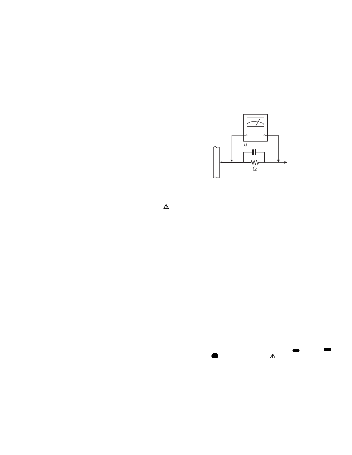
• Alternate check method
Plug the AC line cord directly into the AC outlet. Use an
AC voltmeter having, 1,000Ω per volt or more sensitivity
in the following manner. Connect a 1,500Ω 10W resistor
paralleled by a 0.15µF AC-type capacitor between an exposed metal part and a known good earth ground.
Measure the AC voltage across the resistor with the AC
voltmeter.
Move the resistor connection to each exposed metal
part, particularly any exposed metal part having a return
path to the chassis, and measure the AC voltage across
the resistor. Now, reverse the plug in the AC outlet and
repeat each measurement. Voltage measured any must
not exceed 0.75 V AC (r.m.s.). This corresponds to 0.5
mA AC (r.m.s.).
AC VOLTMETER
(Having 1000
ohms/volts,
or more sensitivity)
0.15 F AC TYPE
Place this
probe on
Good earth ground
1.2 Warning
(1) This equipment has been designed and manufactured to
meet international safety standards.
(2) It is the legal resp onsibility of the repairer to ensure that
these safety standards are maintained.
(3) Repairs must be made in accordance with the relevant
safety standards.
(4) It is essential that safety critical compone nts are replaced
by approved parts.
(5) If mains voltage selector is provided, check setting for local
voltage.
1.3 Caution Burrs formed during molding may be left over on some parts
of the chassis.
Therefore, pay attention to such burrs in the case of preforming repair of this system.
1.4 Critical parts for safety
In regard with component parts appearing on the silk-screen
printed side (parts side) of the PWB diagrams, the parts that are
printed over with black such as the resistor ( ), diode ( )
and ICP ( ) or identified by the " " mark nearby are critical
for safety. When replacing them, be sure to use the parts of the
same type and rating as specified by the manufacturer.
(This regulation dose not Except the J and C version)
each exposed
metal part.
(No.MB040)1-3
Page 4
1.5 Safety Precautions (U.K only)
(1) This design of this product contains special hardware and many circuits and components specially for safety purposes. For con-
tinued protection, no changes should be made to the original design unless authorized in writing by the manufacturer. Replacement parts must be identical to those used in the original circuits.
(2) Any unauthorised design alterations or additions will void the manufacturer's guara ntee; furthermore the manu facturer cannot
accept responsibility for personal injury or property damage resulting therefrom.
(3) Essential safety critical components are identified by ( ) on the Parts List and by shading on the schematics, and must never
be replaced by parts other than those listed in the man ual. Please note however that many el ectrical and mechanical parts in
the product have special safety related characteristics. These characteristics are often not evident from visual inspection. Parts
other than specified by the manufacturer may not have the same safety characteristics as the recommended replacement parts
shown in the Parts List of the Service Manual and may create shock, fire, or other hazards.
(4) The leads in the products are routed and dressed with ties, clamps, tubings, barriers and the like to be separated from live parts,
high temperature parts, moving parts and/or sharp edges for the prevention of electric sh ock and fire ha zard. When se rvice is
required, the original lead routing and dress should be observed, and it should be confi rmed that they have been returned to
normal, after re-assembling.
1.5.1 W arning
(1) Service should be performed by qualified personnel only.
(2) This equipment has been designed and manufactured to meet international safety standards.
(3) It is the legal responsibility of the repairer to ensure that these safety standards are maintained.
(4) Repairs must be made in accordance with the relevant safety standards.
(5) It is essential that safety critical components are replaced by approved parts.
(6) If mains voltage selector is provided, check setting for local voltage.
Burrs formed during molding may be left over on some parts of the chassis. Therefore,
pay attention to such burrs in the case of preforming repair of this system.
1-4 (No.MB040)
Page 5
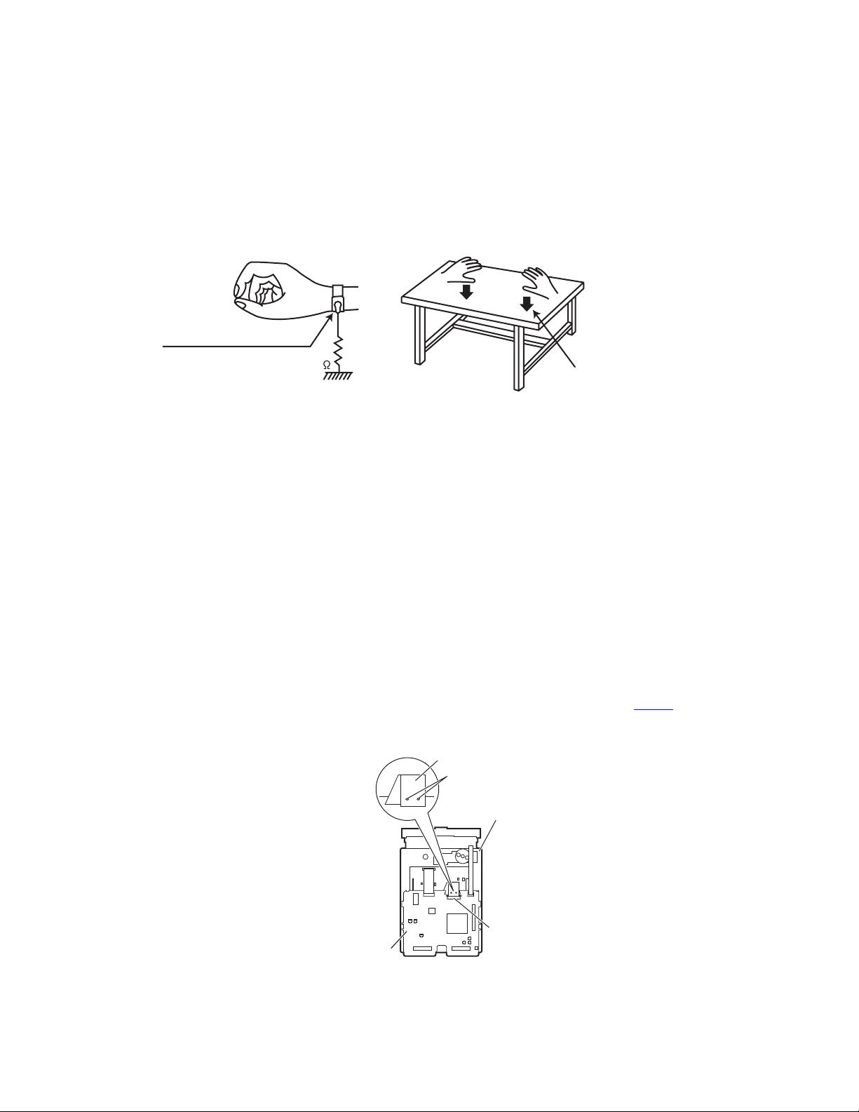
1.6 Preventing static electricity
Electrostatic discharge (ESD), which occurs when static electricity stored in the body, fabric, etc. is discharged, can destroy the laser
diode in the traverse unit (optical pickup). Take care to prevent this when performing repairs.
1.6.1 Grounding to prevent damage by static electricity
Static electricity in the work area can destroy the optical pickup (laser diode) in devices such as DVD players.
Be careful to use proper grounding in the area where repairs are being performed.
(1) Ground the workbench
Ground the workbench by laying conductive material (such as a conducti ve sheet) or an iron plate over it before placing the
traverse unit (optical pickup) on it.
(2) Ground yourself
Use an anti-static wrist strap to release any static electricity built up in your body.
(caption)
Anti-static wrist strap
1M
Conductive material
(conductive sheet) or iron palate
(3) Handling the optical pickup
• In order to maintain quality during transport and before insta llation, both sides of the lase r diode on the replacement o ptical
pickup are shorted. After replacement, return the shorted parts to their original condition.
(Refer to the text.)
• Do not use a tester to check the condition of the laser diode in the optical pickup. The tester's internal power source can easily
destroy the laser diode.
1.7 Handling the traverse unit (optical pickup)
(1) Do not subject the traverse unit (optical pickup) to strong shocks, as it is a sensitive, complex unit.
(2) Cut off the shorted part of the flexible cable using nippers, etc. after replacing the optical pickup. For specific details, refer to the
replacement procedure in the text. Remove the anti-static pin when replacing the traverse unit. Be careful not to take too long
a time when attaching it to the connector.
(3) Handle the flexible cable carefully as it may break when subjected to strong force.
(4) I t is not possible to adjust the semi-fixed resistor that adjusts the laser power. Do not turn it.
1.8 Attention when traverse unit is decomposed *Please refer to "Disassembly method" in the text for the DVD pickup unit.
• Apply solder to the short land sections before the flexible wire is disconnected from the connector CN101
on the DVD servo board.
(If the flexible wire is disconnected without applying solder, the DVD pickup may be destroyed by static electricity.)
• In the assembly, be sure to remove solder from the short land sections after connecting the flexible wire.
Flexible wire
Short land sections
DVD servo board
DVD mechanism assembly
CN101
(No.MB040)1-5
Page 6
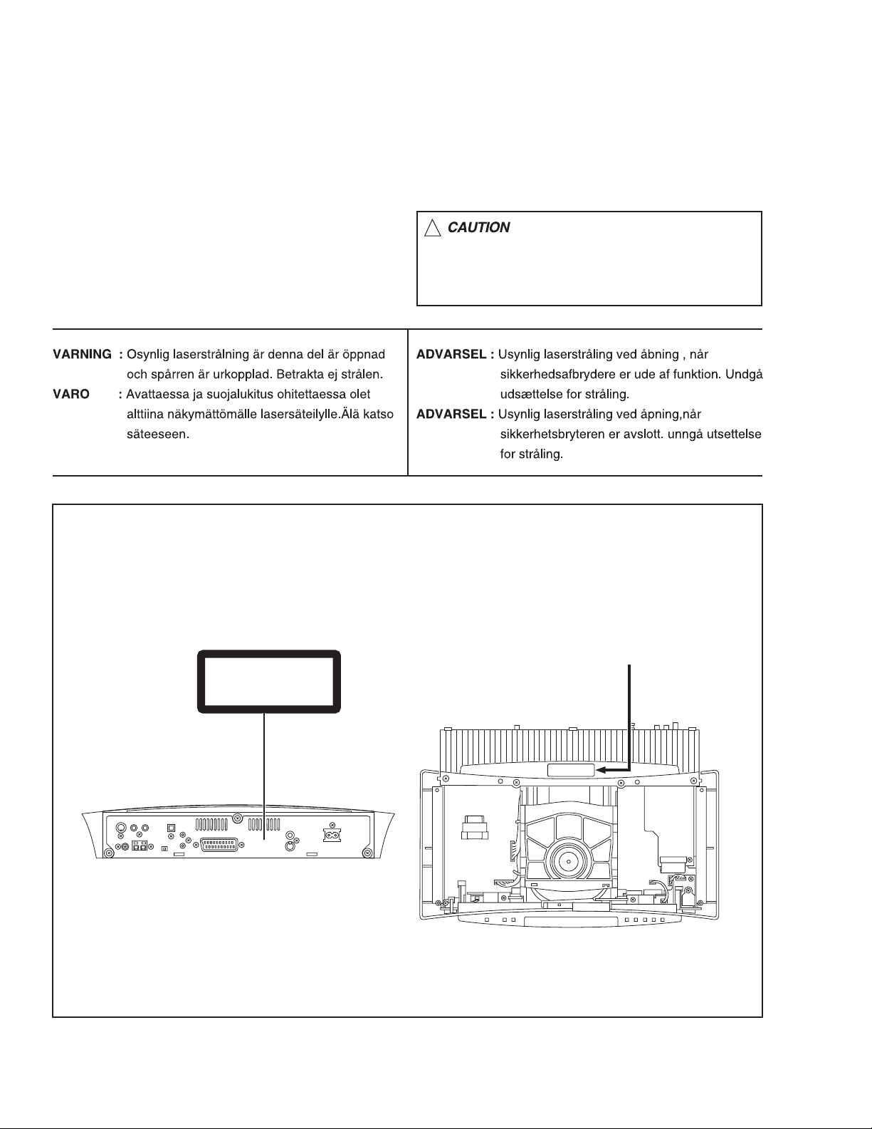
1.9 Important for laser products
1.CLASS 1 LASER PRODUCT
2.DANGER : Invisible laser radiation when open and inter
lock failed or defeated. Avoid direct exposure to beam.
3.CAUTION : There are no serviceable parts inside the
Laser Unit. Do not disassemble the Laser Unit. Replace
the complete Laser Unit if it malfunctions.
4.CAUTION : The compact disc player uses invisible laser
radiation and is equipped with safety switches which
prevent emission of radiation when the drawer is open and
the safety interlocks have failed or are de
feated. It is dangerous to defeat the safety switches.
5.CAUTION : If safety switches malfunction, the laser is able
to function.
6.CAUTION : Use of controls, adjustments or performance of
procedures other than those specified herein may result in
hazardous radiation exposure.
!
Please use enough caution not to
see the beam directly or touch it
in case of an adjustment or operation
check.
REPRODUCTION AND POSITION OF LABEL and PRINT
WARNING LABEL and PRINT
CLASS 1
LASER PRODUCT
CAUTION LABEL
1-6 (No.MB040)
Page 7

SECTION 2
SPECIFIC SERVICE INSTRUCTIONS
This service manual does not describe SPECIFIC SERVICE INSTRUCTIONS.
(No.MB040)1-7
Page 8
SECTION 3
DISASSEMBLY
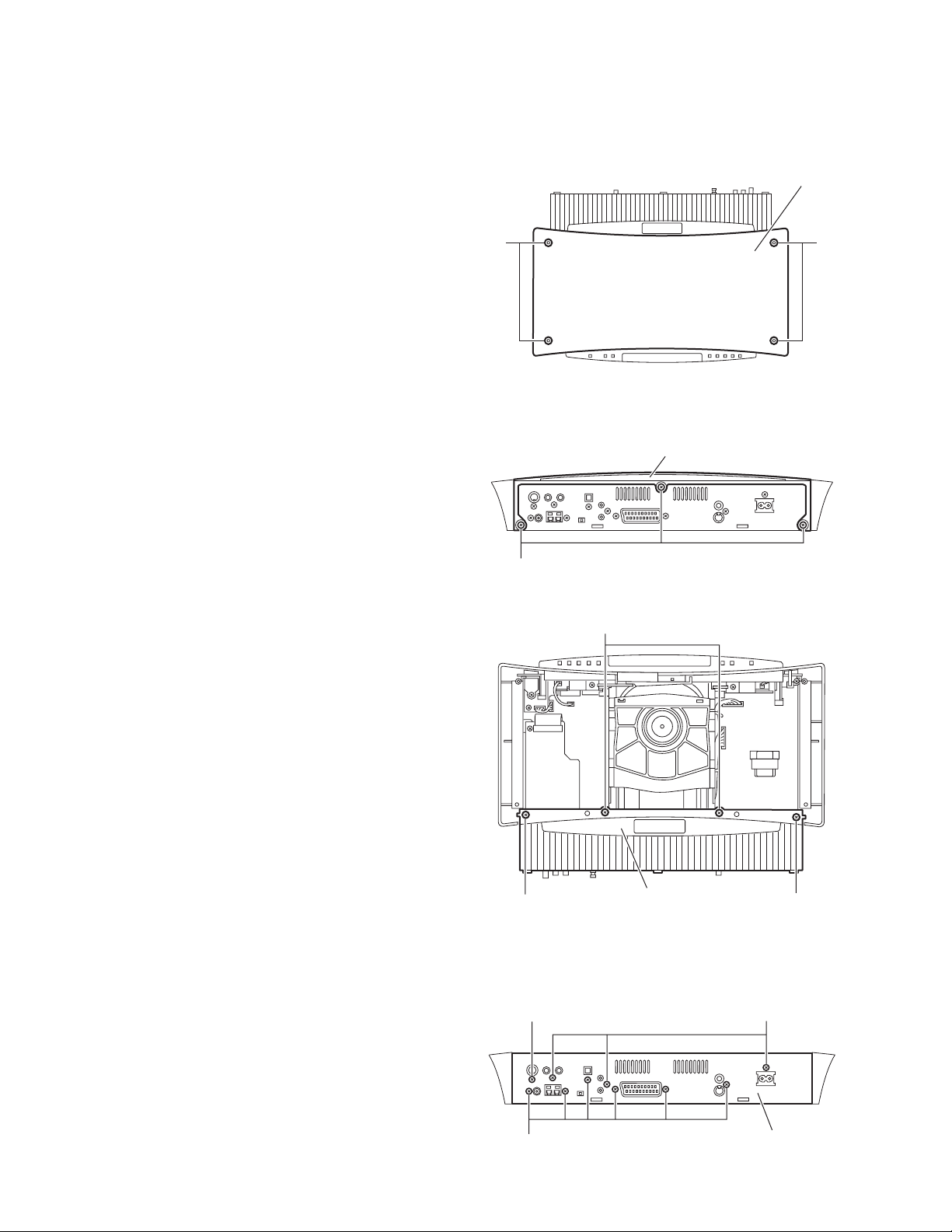
3.1 Main body section
3.1.1 R emoving the top plate
(See Fig.1)
(1) From the top side of the main body, remove the four screws
A attaching the top plate.
(2) Remove the top plate from main body.
3.1.2 Removing the rear cover
(See Figs.2 and 3)
• Prior to performing the following procedures, remove the top
plate.
(1) From the rear side of the main body, remove the three
screws B attaching the rear cover. (See Fig.2)
(2) From the top side of the main body, remove the two screws
C and two screws D attaching the rear cover. (See Fig.3)
(3) Remove the rear cover upward.
Top plate
AA
Fig.1
Rear cover
3.1.3 Removing the rear panel
(See Fig.4)
• Prior to performing the following procedures, remove the top
plate and rear cover.
(1) From the rear side of the main body, remove the nine
screws E and screw F attaching the rear panel.
(2) Remove the rear panel from main body.
B
Fig.2
D
C
Rear cover
Fig.3
C
FE
1-8 (No.MB040)
E
Rear panel
Fig.4
Page 9
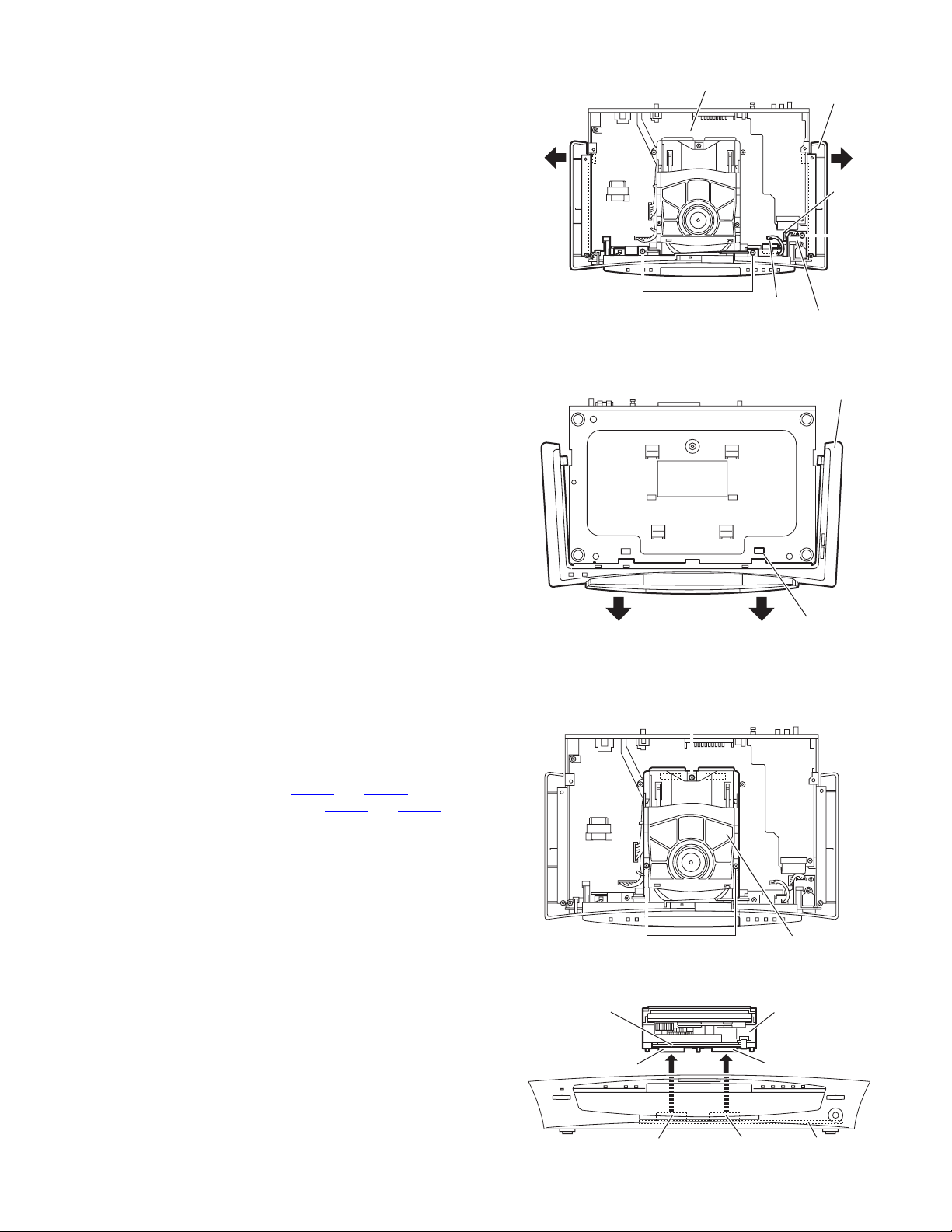
3.1.4 Removing the front panel assembly
(See Figs.5 and 6)
• Prior to performing the following procedures, remove th e top
plate.
(1) From the top side of the head phone board, remove the
three screws G attaching the front panel assembly. (See
Fig.5)
(2) Disconnect the card wires from the connectors CN408
on the main board. (See Fig.5)
CN412
(3) Extend the side of the front panel assembly in the direction
of the arrows a. (See Fig.5)
(4) Remove the front panel assembly in the direction of the ar-
rows c, while releasing the claw b. (See Fig.6)
and
G
Main board
Fig.5
Front panel
assembly
aa
CN412
G
CN408
Head phone
board
Front panel
assembly
3.1.5 Removing the DVD mechanism assembly
(See Figs.7 and 8)
• Prior to performing the following procedures, remove th e top
plate and rear cover.
(1) From the top side of the main body, remove the two screws
H and screw J on the DVD mechanism assembly. (See
Fig.7)
(2) Disconnect the connectors CN502
servo board from the connectors CN405
main board while lifting the DVD mechanism assembly upward. (See Fig.8)
(3) Take out the DVD mechanism assembly from the main
board.
and CN503 on the DVD
and CN406 on the
DVD servo
board
CN502
claw
c
Fig.6
c
b
J
H
Fig.7
DVD mechanism
assembly
DVD mechanism
assembly
CN503
CN406
Fig.8
CN405
Main board
(No.MB040)1-9
Page 10

3.1.6 Removing the DSP board
(See Figs.9 and 10)
• Prior to performing the following procedures, remove the top
plate and rear cover.
(1) From the top side of the DSP board, disconnect the card
wires from the connectors CN401
Fig.10)
(2) Remove the screw K attaching the DSP board from the
section d of the barrier. (See Fig.10)
(3) From the back side of the main body, remove the screw L
and two screws M attaching the DSP board. (See Fig.9)
Reference:
• When attaching the DSP board, hang the DSP board on the
section d of the barrier. (See Fig.10)
3.1.7 Removing the tuner
(See Figs.9 and 11)
• Prior to performing the following procedures, remove the top
plate, rear cover and DSP board.
(1) From the top side of the tuner, disconnect the card wire
from the connector CN1
(2) From the back side of the main body, remove the two
screws N attaching the tuner. (See Fig.9)
(3) Take out the tuner from the main bod y.
on the tuner. (See Fig.11)
on the DSP board. (See
LM
N
Section d
K
CN401
Rear panel
Fig.9
DSP board
Tuner
Fig.10
CN1
Fig.11
1-10 (No.MB040)
Page 11

3.1.8 Removing the main board
(See Fig.12)
• Prior to performing the following procedures, remove th e top
plate, rear cover, rear panel, DVD mechanism, DSP board and
tuner.
(1) From the top side of the main b oard, disconnect the card
wires from the connectors CN408
board.
(2) From the top side of the power board, disconnect the card
wires from the connectors CN901
board.
(3) Remove the three screws P attaching the main board.
(4) Take out the main board from the main body.
Reference:
• After connecting the wire to the connectors CN901
on the power board, fix the wire by the wire clamp.
CN902
and CN412 on the main
and CN902 on the power
and
CN412
CN408
P
CN901
CN902
3.1.9 Removing the power board
(See Fig.13)
• Prior to performing the following procedures, remove th e top
plate, rear cover and rear panel.
(1) From the top side of the main bo dy, disconnect the card
wires from the connectors CN901
board.
(2) Remove the four screws Q attaching the power board.
(3) Take out the power board from the bottom chassis.
Reference:
• Remove the front panel assembly and DVD mechanism as-
sembly as required.
• After connecting the wire to the connectors CN901
CN902 on the power board, fix the wire by the wire clamp.
and CN902 on the power
and
P
Wire clamp
Wire clamp
Power board
Main board
Fig.12
Q
CN901
CN902
Power board
Q
Fig.13
(No.MB040)1-11
Page 12

3.2 Front panel assembly section
• Prior to performing the following procedures, remove the top
plate and front panel assembly.
3.2.1 Removing the FL board
(See Figs.1 and 2)
(1) From the inside of the FL board, disconnect the wire from
the connector CN502
(2) Remove the FL board in the direction of the arrow e, while
lifting the claws f upward. (See Fig.1)
(3) Take out the FL board from front panel assembly.
Reference:
• Before attaching the FL board, be careful not to damage the
projection part g.
• Before attaching the FL board, insert FL board in the section
h.
3.2.2 Removing the head phone board
(See Fig.1)
• Remove the screw R attaching the head phone board, take out
the head phone board.
on the volume board. (See Fig.2)
R
Head phone board
Projection part g
Claw f
FL board
e
Fig.1
e
Claw f
3.2.3 Removing the switch board
(See Fig.3)
• Prior to performing the following procedures, remove the FL
board.
• Remove the two screws S attaching the switch board, take out
the switch board.
3.2.4 Removing the volume board
(See Fig.3)
• Prior to performing the following procedures, remove the FL
board.
• Remove the two screws T attaching the volume board, take out
the volume board.
Claw
f Claw f
Section h
Switch board Volume board
S
CN502
FL board
Fig.2
T
Fig.3
1-12 (No.MB040)
Page 13

3.3 DVD mechanism section
• Prior to performing the following procedures, remove the top plate
and rear cover, and remove the DVD mechanism assembly.
3.3.1 Removing the tray
(See Figs.1 and 2)
(1) From the left side of the DVD mechanism a ssembly, push
the slide cam in the direction of the arrow 1 and then pull
out the tray in the direction of the arrow 2. (See Fig.1)
(2) Push the tray stoppers a in the direction of the arrow 3, pull
out the tray in the direction of the arrow 4. (See Fig.2)
3.3.2 Attaching the tray
(See Fig.2)
When attaching the tray, insert the tray to the rail of the DVD
mechanism assembly and then push th e tray in the DVD mechanism assembly.
Tray
2
1
Slide cam
Fig.1
Tray stoppers a
3
4
Tray
3.3.3 Removing the DVD servo board
(See Fig.3)
(1) From the bottom side of the DVD mechanism assembly,
disconnect the card wires from the connectors CN201
on the DVD servo board.
CN202
Caution:
disconnecting the flexible wire from connector CN101
the DVD servo board.
If the flexible wire is disconnected without attaching solder, the DVD pickup unit may be destroyed by static
electricity.
(2) Release the locks of the connector CN101
of the arrow 1) on the DVD servo board, disconnect the
flexible wire.
(3) Release the locks of the connector CN101
vo board in the direction of the arrow 1, disconnect the flexible wire.
Caution:
In the assembly, be sure to remove solders from the
short land sections b after connecting the flexible wire to
the connector CN101
(4) While pushing the claw c of the DVD mechanism assembly
in the direction of the arrow 2, remove the DVD servo board
in an upward direction.
on the DVD servo board.
(in the direction
on the DVD ser-
and
on
Card wire
CN201
Claw c
DVD mechanism assembly
Fig.2
Flexible wire
Short land sections b
DVD mechanism assembly
11
2 22
Card wire
CN202
Claw c
DVD servo board
CN101
Fig.3
(No.MB040)1-13
Page 14

3.3.4 Removing the clamper base
(See Fig.4)
(1) From the top side of the DVD mechanism assembly, re-
move the four screws A attaching the clamper base.
(2) Remove the clamper base from the bosses d of the loading
base in an upward direction, remove the clamper base
from the sections e while sliding it in the direction of the arrow.
Boss d
Clamper base
AA
Section e
3.3.5 Removing the tray drive board
(See Fig.5)
• Prior to performing the following procedures, remove the
clamper base.
(1) From the bottom side of the DVD mechanism assembly, re-
move the solders from the soldered sections f on the tray
drive board.
(2) Remove the screw B attaching th e tray drive board to the
DVD mechanism assembly.
Boss d
Connector
A A
Fig.4
Card wire
Soldered
sections f
Loading base
Section e
DVD mechanism assembly
1-14 (No.MB040)
Motor
B
Tray drive board
Fig.5
Page 15

3.3.6 Removing the motor
(See Fig.6)
• Prior to performing the following procedures, remove the
clamper base and tray drive board.
(1) From the top side of the DVD mechan ism assembly, re-
move the belt of the pulley gear.
Note:
Take care not to attach grease on the belt.
(2) Remove the screw C attaching the motor to the DVD mech-
anism assembly.
3.3.7 Removing the DVD traverse mechanism assembly
(See Fig.7)
• Prior to performing the following procedures, remove the DVD
servo board and clamper base.
(1) From the top side of the DVD mechan ism assembly, re-
move the four screws D attaching the DVD traverse mechanism assembly to the loading base.
(2) Take out the DVD traverse mechanism assembly from the
loading base.
Pulley gear
DVD mechanism assembly
Belt
C
Motor
Fig.6
DVD traverse mechanism assembly
D D
DD
Fig.7
Loading base
(No.MB040)1-15
Page 16

3.3.8 Removing the DVD pickup unit
t
t
w
(See Figs.8 to 10)
• Prior to performing the following procedures, remove the DVD
servo board, clamper base and DVD traverse mechanism assembly.
(1) From the top side of the DVD traverse mechanism assem-
bly, remove the screw E attaching the plate and torsion
spring. (See Fig.8)
(2) Remove the shaft from the section g and then remove the
shaft from the section h. (See Fig.9)
(3) Disengage the section i of the DVD pickup unit and then re-
move the DVD pickup unit with the shaft. (See Fig.9)
(4) Pull the shaft out of the DVD pickup unit. (See Fig.10)
(5) Remove the two screws F attaching the SW. actuator. (See
Fig.10)
DVD pickup unit
Section i
Section h
Shaf
Section g
Fig.9
3.3.9 Attaching the DVD pickup unit
(See Figs.8, 10 to 12)
Reference:
Refer to the explanation of "Removing the DVD pickup unit" on
the preceding page.
(1) Attach the SW. actuator and shaft to the DVD p ickup unit.
(See Fig.10)
(2) Engage the section i of the DVD pickup unit to the shaft of
the DVD traverse mechanism assembly first, and set the
both ends of the shaft of the DVD pickup unit in the sections
g and h of the DVD traverse mechanism assembly. (See
Fig.11)
(3) Slide the DVD pickup unit all the way in the direction of the
arrow. (See Fig.12)
(4) Mesh the lead screw to the section j of DVD pickup unit and
then set the end of the lead screw to the section k. (See
Fig.12)
(5) Attach the torsion spring. (See Fig.8)
(6) Attach the plate. (See Fig.8)
E
Plate
Torsion spring
DVD pickup unit
SW. actuator
Section i
Shaft
F
DVD pickup uni
Shaft
Fig.10
DVD pickup unit
Section h
1-16 (No.MB040)
DVD traverse mechanism assembly
Fig.8
Section g
DVD pickup unit
DVD traverse mechanism assembly
Fig.11
Section k
Section j
Lead scre
Fig.12
Page 17

3.3.10 Removing the spindle motor boar d
r
(See Figs.13 and 14)
• Prior to performing the following procedures, remove the DVD
servo board, clamper base and DVD traverse mechanism assembly.
(1) From the top side of the DVD traverse mechanism assem-
bly, remove the feed motor wire that is soldered to the spindle motor board. (See Fig.13)
(2) From the bottom side of the DVD traverse mechanism as-
sembly, remove the three screws G attaching the spindle
motor board. (See Fig.14)
Spindle motor board
Remove the solders.
Feed moto
wire
DVD traverse mechanism assembly
Fig.13
G
DVD traverse mechanism assembly
Fig.14
G
(No.MB040)1-17
Page 18

3.3.11 Removing the feed motor
r
(See Figs.15 to 17)
• Prior to performing the following procedures, remove the DVD
servo board, clamper base and DVD traverse mechanism assembly.
(1) From the top side of the DVD traverse mechanism assem-
bly, remove the feed motor wire that is soldered to the spindle motor board. (See Fig.15)
(2) Remove the screw H attaching the feed holder assembly
and then take out the feed holder assembly. (See Fig.15)
(3) Remove the screw J attaching the thrust spring. (See
Fig.16)
(4) Remove the feed gear and lead screw in the direction of the
arrow. (See Fig.16)
(5) Remove the two screws K attaching the feed motor. (See
Fig.17)
Spindle motor board
DVD traverse mechanism assembly
Fig.15
Feed holder assembly
Remove the solders.
Feed holde
assembly
H
Feed motor
wire
Feed motor
H
Lead screw
Feed motor
Feed gear
Thrust spring
J
Fig.16
Feed holder assembly
1-18 (No.MB040)
K
Fig.17
Page 19

3.4 Speaker section
A
3.4.1 Removing the amplifier assembly
(See Figs.1 and 2)
(1) From the rear side of the speaker main body, remove four
screws A attaching the heat sink cover. (See Fig.1)
(2) Remove the nine screws B attaching amplifier assembly.
(See Fig.2)
(3) Move the amplifier assembly backward and disconnect the
wire from connector CN402
assembly. (See Fig.2)
in the lower part of the amplifier
A
Amplifier
assembly
Heat sink
cover
A
Fig.1
mplifier
assembly
B
B
CN402
Fig.2
(No.MB040)1-19
B
Page 20

3.4.2 Removing the rear panel
(See Fig.3)
• Prior to performing the following procedures, remove the am-
plifier assembly.
(1) Remove the four screws C, twelve screws D and screw E
attaching the rear panel.
(2) Take out the rear panel from the ampli fier assembly.
D
E
Rear panel
C
D
D
3.4.3 Removing the SP terminal board
(See Figs.4 and 5)
• Prior to performing the following procedures, remove the am-
plifier assembly and rear panel.
(1) From the top side of the amplifier assembly, disconnect the
card wires from the connectors CN101
mother board. (See Figs.4 and 5)
(2) Disconnect the connectors CN401
the SP terminal board from the connectors CN501, CN503
and CN504 on the mother board while lifting the SP terminal board upward. (See Fig.5)
(3) Take out the SP terminal board from the amplifier assem-
bly.
Reference:
When attaching the SP terminal board, insert the SP terminal
board in the section a of the barrier.
and CN102 on the
, CN403 and CN404 on
C
D
C
Mother
board
SP terminal
board
CN101
CN102
Tie band
Section a
C
D
Fig.3
1-20 (No.MB040)
Amplifier
assembly
CN101
CN102
Tie band
Fig.4
CN401
CN403
CN404
Fig.5
Amplifier
assembly
CN501
CN503
CN504
Mother
board
SP terminal
board
Page 21

3.4.4 Removing the mother board assembly
(See Fig.6)
• Prior to performing the following procedures, remove the am-
plifier assembly, rear panel and SP terminal board.
(1) From the top side of the amplifier assembly, disconnect the
card wires from the connectors CN151
board.
(2) From the top side of the amplifier assembly, remove the
five screws F attaching the mother board.
(3) Take out the mother board assembly from the amplifier as-
sembly.
3.4.5 Removing the mother board
(See Fig.7)
• Prior to performing the following procedures, remove the am-
plifier assembly, rear panel, SP terminal board and mother
board assembly.
(1) From the bottom side of the mother board, remove the two
screws G and two screws H attaching the mother board.
(2) Disconnect the connectors CN521
CN532 on the mother board while lifting the mother board
upward, and take out the mother board.
on the mother
, CN522, CN531 and
Mother
board
F
CN151
CN522
G
Fig.6
H
F
Amplifier
assembly
Mother board
CN531
CN521
G
CN532
H
Fig.7
(No.MB040)1-21
Page 22

3.4.6 Removing the power amplifier board (A)
(See Figs.8 and 9)
• Prior to performing the following procedures, remove the am-
plifier assembly, rear panel, SP terminal board, mother board
assembly and mother board.
(1) Remove the three screws J attaching the heat sink to the
power amplifier board (A). (See Fig.8)
(2) From the bottom side of the power amplifier board (A), dis-
engage the four sections b of the engagement. (See Fig.9)
(3) From the top side of the power amplifier board (A), dise n-
gage the section c of the engagement to the direction of the
arrow. (See Fig.9)
(4) Remove the power amplifier board (A) from the P.TR hold-
er (A).
3.4.7 Removing the power amplifier board (B)
(See Figs.8 and 10)
• Prior to performing the following procedures, remove the am-
plifier assembly, rear panel, SP terminal board, mother board
assembly and mother board.
(1) Remove the three screws K attaching the heat sink to the
power amplifier board (B). (See Fig.8)
(2) From the bottom side of the power amplifier board (B), dis-
engage the four sections c of the engagement. (See Fig.9)
(3) From the top side of the power amplifier board (B), dise n-
gage the section d of the engagement to the direction of the
arrow. (See Fig.9)
(4) Remove the power amplifier board (B) from the P.TR hold-
er (B).
J
Power
amplifier
board (A)
1
2
(Bottom side)
P.TR holder (A)
P.TR holder (B)
Fig.8
Sections b
CN251
K
Power
amplifier
board (B)
K
Heat sink
P.TR holder (A)
Power amplifier
board (A)
2
1
(Bottom side)
Section e
CN252
Sections b
Fig.9
Sections d
CN351
CN352
Section c
1
2
(Bottom side)
Power amplifier
board (B)
2
1
1-22 (No.MB040)
P.TR holder (B)
(Bottom side)
Sections d
Fig.10
Page 23

3.4.8 Removing the power transformer
r
A
L
(See Fig.11)
• Prior to performing the following procedures, remove the am-
plifier assembly, rear panel, SP terminal board and mother
board assembly.
(1) Remove the tie band, and remove the four screws L attach-
ing the power transformer.
(2) Take out the power transformer from the amplifier assem-
bly.
3.4.9 Removing the speaker net
(See Figs.12 and 13)
(1) Insert the tip of a flat-bladed screwdriver or similar tool into
the space between the speaker main body and speaker
net, and lift the speaker net little by little to remove. (See
Figs.12 and 13)
Note:
To prevent damaging the speaker net and speaker main
body, insert cushioning plates etc. to the section f and
below the tip of the flat-bladed screwdriver or similar tool.
(2) Take out the speaker net from the speaker main body.
L
Power
transforme
Tie band
C bracket
L
Fig.11
Speaker net
Section f
Speaker net
Speaker main body
Section f
Fig.12
Chshioning
blate,etc.
Fig.13
Speaker main body
Flat-bladed
screwdriver,etc.
(No.MB040)1-23
Page 24

3.4.10 Removing the speaker
(See Figs.14 and 15)
(1) From right side of the speaker main body, remove the eight
screws M attaching the speaker. (See Fig.14)
(2) Take out the speaker from the speaker main body. (See
Fig.15)
(3) Disconnect the wires from the terminal of the speaker. (See
Fig.15)
M
Speaker
Speaker main body
M
Fig.14
Speaker main body
Terminal
Fig.15
Speaker
1-24 (No.MB040)
Page 25

SECTION 4
ADJUSTMENT
4.1 TEST mode (See Fig.1)
(1) This model is provided with a test mode for use in production QC, service and repair.
(2) Before executing the test mode, if a tray is not completely close up, make power to standby from on to close up the tray.
(3) After confirm that a tray is completely close up, pull off the power plug.
(4) Insert the power plug to the outlet while pressing the "STOP" and "OPEN/CLOSE" buttons on the main unit at the same time.
(5) The opening screen showing the version number is displayed.
(6) The test mode includes the following four different states, which are switched over every time the "CHOICE" button on the remote
control unit is pressed.
(7) The test mode is exited when the power is switched on or off.
The FL display shows "TEST ". : Area code
STOP button
STANDBY/ON button
CHOICE button
FL display
Fig.1
NOTE:
(1) Press the "CHOICE" button once: Firmware version di splay mod e / The F L display shows the versio n numbers of the micro-
computers in use.
Displayed information: [System firm] [Front-end (FE) firm] [Back-end (BE) firm]
(2) Press the "CHOICE" button twice: Indicator check mode / All FL and LED segments lig ht up.
(3) Press the "CHOICE" button three times: Mechanism check mode / The FL display shows "CHECK".
(4) Press the "CHOICE" button four times: Front-end check mode / The FL display shows "EXPERT".
OPEN/CLOSE button
(No.MB040)1-25
Page 26

SECTION 5
TROUBLESHOOTING
This service manual does not describe TROUBLESHOOTING.
1-26 (No.MB040)
Page 27

(No.MB040)1-27
Page 28

VICTOR COMPANY OF JAPAN, LIMITED
AV & MULTIMEDIA COMPANY AUDIO/VIDEO SYSTEMS CATEGORY 10-1,1chome,Ohwatari-machi,Maebashi-city,371-8543,Japan
(No.MB040)
Printed in Japan
WPC
 Loading...