

Page 1
SCHEMATIC DIAGRAMS
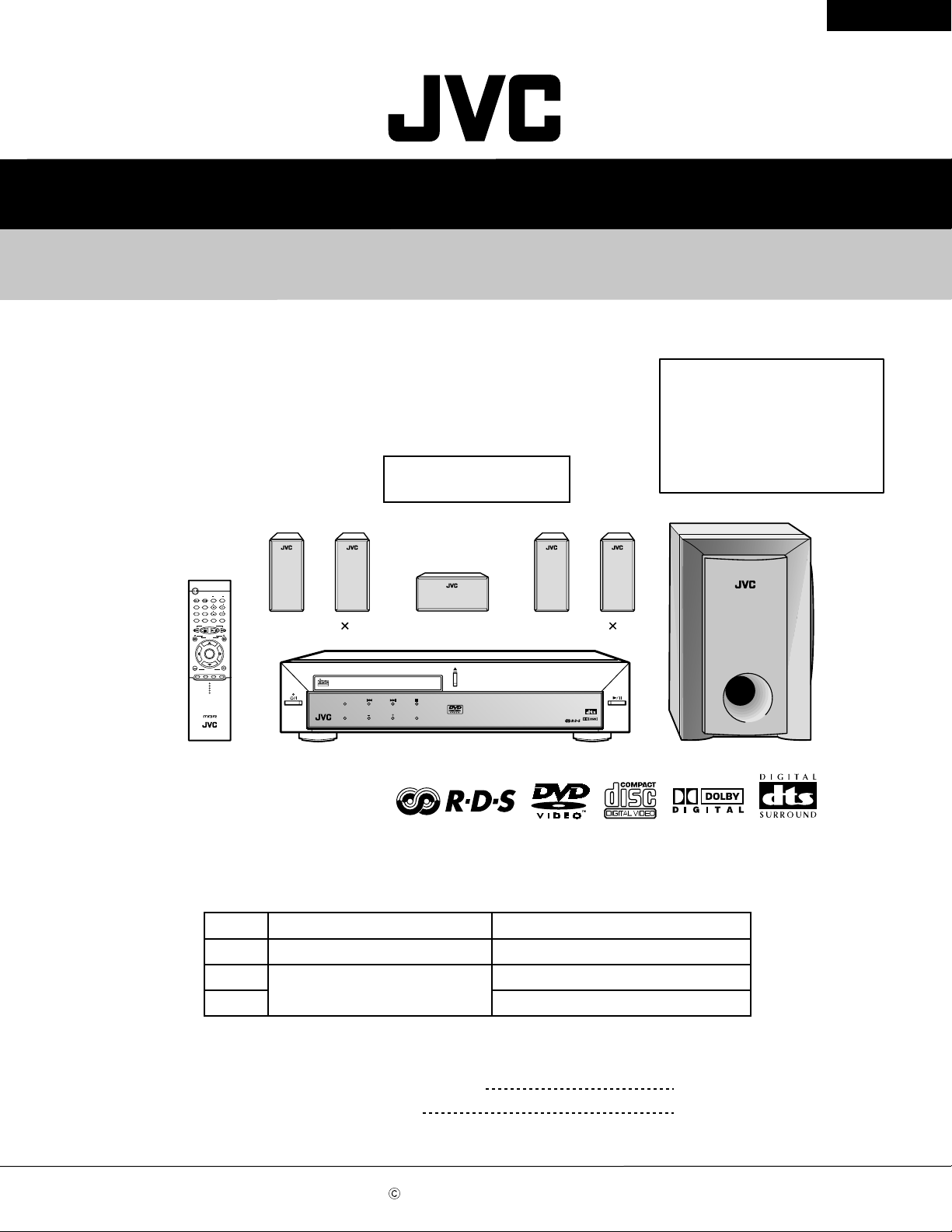
DVD DIGITAL CINEMA SYSTEM
TH-A5R
STANDBY/ON
AUDIO
CONTROL
VCR
TV
OFF
TV CHANNEL
MENU
TOP MENU
AUDIO/
SUBTITLE
TV VOLUME
FM MODE
STEP
DISPLAY
RETURN
TUNER PRESET
DOWN UP
REW FF
VCR CHANNEL
TUNING
B.SEARCH F.SEARCH
ENTER
VOLUME
DVD FM/AM AUX MUTING
RM-STHA5R
DVD CINEMA SYSTEM
TH-A5R
Area suffix
B -------------------------- U.K.
E ------ Continental Europe
CD-ROM No.SML200212
EN ------- Northern Europe
EV --------- Eastern Europe
Supplement
VCR
ON
TV/VIDEO
COMPACT
DIGITAL VIDEO
STANDB
Y
AUDIO/FM MOD
STANDBY/ON
E
D
SP
OLUMESOURC
V
SP-XCA5SP-XSA5 2
E
DVD DIGITAL CINEMA
SYSTEM TH-A5R
SP-XSA5 2
DIGITAL
SURROUND
DIGITAL
XV-THA5R SP-WA5
EE ---- Russian Federation
In No.21046BSCH, change of the schematic diagram & circuit board of MPEG
section were missing. Please add this supplement to No.21046BSCH.
Page
2-8
2-12
Contents
Standard schematic diagrams
Items
DVD MPEG section
DVD MPEG board (Forward side)
Printed circuit boards
2-13
DVD MPEG board (Reverse side)
Contents
Standard schematic diagram
Printed circuit boards
COPYRIGHT 2002 VICTOR COMPANY OF JAPAN, LTD.
2-1
2-2
No.21046CSCH
Dec. 2002
Page 2

TH-A5R
In regard with component parts appearing on the silk-screen pr inted side (par ts side) of
the PWB diagrams, the parts that are printed over with black such as the resistor ( ),
diode ( ) and ICP ( ) or identified by the " " mark nearby are critical for safety.
(This regulation does not correspond to J and C version.)
Page 3
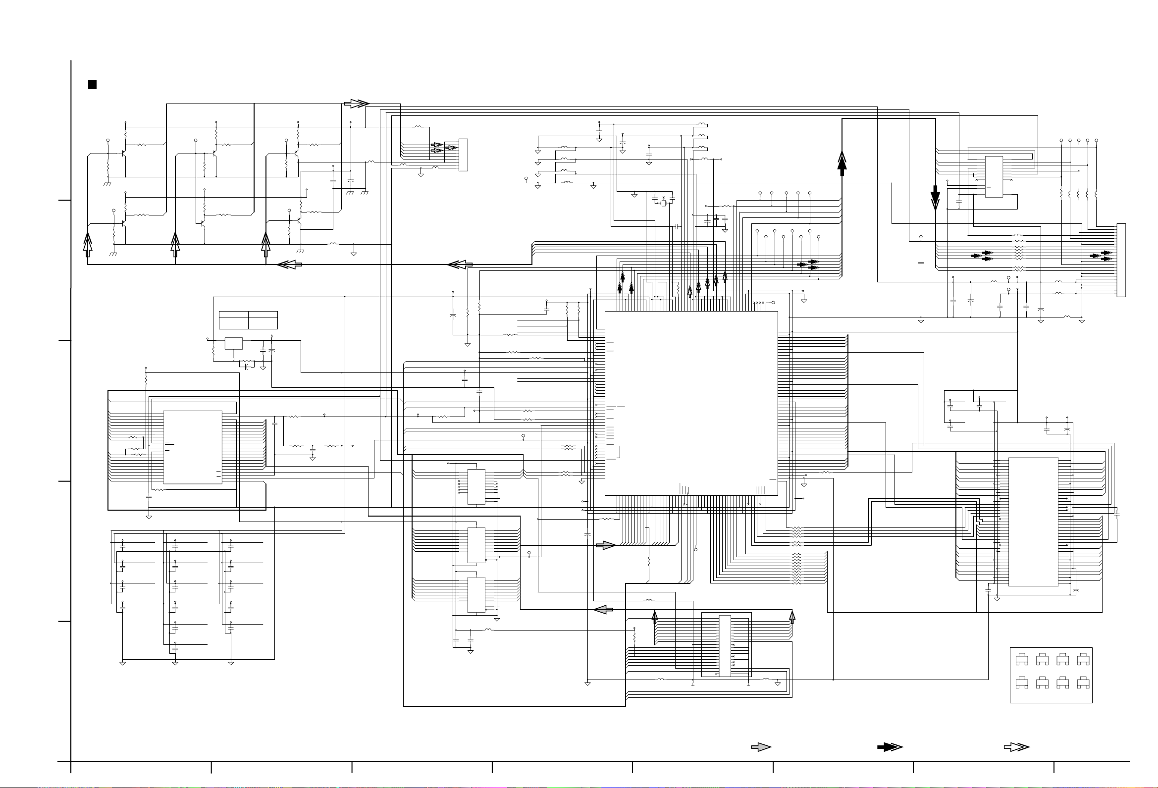
Standard schematic diagram
DVD MPEG section
TH-A5R
+5V_VID
VR1
150
5
C
VID_C
VOGND
VID_U
VR9
82
VR3
000
1
VR2
82
S_VIDEO_C
23
Q3
1
KSA812
+5V_VID
VR10
U
VR11
150
000
23
Q6
KSA812
VIDEO_U
1
1
VOGND
+5V_VID
VR5
150
Y
1
VID_Y
1
VR4
82
+5V_VID
VR7
150
23
Q5
1
KSA812
I_SAT_OPT(DEL)
+5V_VID
VR16
COMP
150
VR6
000
S_VIDEO_Y
23
Q4
KSA812
VID_COMP
VR17
000
1
1
VR15
56
COMP_OUT
23
Q8
KSA812
+5_VID
+5V_VID
VR13
VR14
VR8
000
VIDEO_Y1
VID_V
150
000
V
1
VIDEO_V
23
Q7
1
KSA812
VR12
82
VOGND
+5V_VID
VJL1
000(2012)
C30
VC10
220u/16
0.1u
VOGND
VOGND
VL1
FBSMT
GND
OL1
FBSMT
FBSMT
COMP_OUT
S_VIDEO_C
S_VIDEO_Y
VIDEO_Y1
VIDEO_U
VIDEO_V
IL1
DEL
GND
CON_WAFER_1m/m_SMD_ST
OL2
FBSMT
J21
1
2
3
4
5
6
7
8
9
10
T o VW2
TPN3
VGND
PLL_VDD
C71
0.1u
REF_VDD
C68
MGND
PLL_GND
+
47u/16
REF_GND
PLL_GND
PLL_GND
DVDD
C67
0.1u
DVSS
13.5MHz Fundamental
C96
3
1
15pF
X1
L52
FBSMT
PLL_GND
L54
FBSMT
REF_GND
L53
FBSMT
DVSS
L55
CIC21C
VGND
1
VID_V
VID_U
VID_Y
VID_C
VID_COMP
4
R56
R98
4.7K
4.7K
R6 33 ohm
R8 33 ohm
3.3V
VDD
47u/16
VDD
140
141
142
143
144
139
145
146
147
148
149
150
152
153
151
154
155
156
XCK
BCK
VDD
GND
LRCK
VDDP
GNDP
IEC958
ADATA1
ADATA2
ADATA3
157
DAI_DATA
158
DAI_BCK/SYSCLKBP
159
DAI_LRCK/IEC958BP
160
I2C_CL
161
I2C_DA
162
RTS1
163
RXD1
164
TXD1
165
CTS1
166
GNDP
167
VDDP
168
SDDATA7
169
SDDATA6
170
SDDATA5
171
SDDATA4
172
GND
173
VDD
174
SDDATA3
175
SDDATA2
176
SDDATA1
177
SDDATA0
178
SDREQ
179
SDEN
180
GNDP
181
VDDP
182
SDERROR
183
SDCLK
184
VSYNC / HIRQ1
185
RTS2
186
RXD2
187
TXD2
188
CTS2
189
VNW
190
ALE
191
HCS4
192
HCS3
193
HCS2
194
HCS1
195
HCS0
196
VDDP
197
TRST
198
TDO
JTAG
199
TDI
200
TMS
201
TCK
202
RESET
203
BUSCLK
204
GND
205
VDD
206
HA3
207
HA2
208
GNDP
GND
R63
C73
+
HD13
HD12
HA1
HD15
HD14
VDDP
567891011131214151617181922202123242526272829
234
1
33 ohm
UPD15
UPD12
UPD11
UPD14
UPD13
(UPD0-15)
XVDD
AVSS2
AVSS1
AVDD2
AVDD1
ADATA0
XIN / VCLK216BP
ZiVA-5Xi MPEG DECODER
HD11
HD10
HD9
HD8
HD7
GNDP
VDDP
HD6
HD5
HD4
HD3
HD2
UPD2
UPD9
UPD5
UPD10
UPD8
UPD4
UPD7
UPD3
UPD6
R9
33 ohm
UPD_7
PL3
FBSMT
UPD[15:0]
(UPD0-15)
GND
/LDRRST
UPD15 DD7
3.3V
UPD13 DD5
UPD11 DD3
UPD10 DD2
R99
1K
HDMARQ DMARQ
UDS
/DTACK
HDMACK
HIRQ1
UPA_2
/IDE_CS0
L32
FBSMT
/IDE_CS1
UPA_3
UPD_7
VDD
I2C_CL
I2C_DA
DEMPH
4.7K
R107
D_MUTE
PWR_CNTL
R112 4.7K
R111 4.7K
1
UPA3
UPA2
UPA1
ALE
1
3.3V
NO CONNECT
NO CONNECT
NO CONNECT
5.6K
NO CONNECT
NO CONNECT
CTS2
ALE
/FLASH_CS
C55
0.1u
R57 33 ohm
R59 33 ohm
R54
R
R53
+
C85
AMS317
R60:220OHM
R61:120OHM
LM1117DT-1.8
VDD 3.3V
2
R60
220
3.3V_FLASH
R31
4.7K
/SYS_RST
UPA177
3
2
UPA16
UPA15
UPA14
UPA13
UPA12
UPA11
UPA10
UPA9
UPA22
UPA21
UPA20
UPA19
UPA18
UPA8
UPA7
UPA6
UPA5
UPA4
UPA3
UPA2
3.3V
VDD
3.3V
3.3V
GND
UDS
2
A14
3
A13
4
A12
5
A11
6
A10
7
A9
841
A8 DQ13
R34
9
A21
10
0ohm
R33
DEL
0ohm
U8/12PIN
C80
0.1u
U8/30PIN
C90
0.1u
U8/32PIN
C106
0.1u
C77
0.1u
A20
11
WE
12
RESET
13
SST39VF800A
ACC
14
WP
R10
15
A19
0ohm
16
A18
17
A17
18
A7
19
A6
20
A5
21
A4
22
A3
23
A2
24
A1
R32
4.7K
8M FLASH MEMORY
3.3V
C75
0.1u
3.3V
C64
0.1u
VDD
C89
0.1u
3.3V
C62
0.1u
3.3V
C61
0.1u
3.3V
U8/104PIN
C59
0.1u
C101
0.1u
GND
GND
ADJ_2.5V
481
A16A15
47
Vi/o
46
VSS
45
DQ15
44
DQ7
43
DQ14
42
DQ6
40
DQ5
U6
39
DQ12
38
DQ4
37
VCC
36
DQ11
35
DQ3
34
DQ10
33
DQ2
32
DQ9
31
DQ1
30
DQ8
29
DQ0
28
OE
27
VSS
26
CE
25
A0
U8/63PIN
U8/74PIN U8/173PIN
U8/80PIN
U8/87PIN
U8/98PIN
OUT
VDD
VDD
3.3V
3.3V
VDD
GND
U9
IN
ADJ
1
R61
C84
10u/16
U8/145PIN
C88
0.1u
C87
0.1u
U8/181PIN
C79
0.1u
U8/196PINU8/44PIN
C107
0.1u
U8/205PIN
C86
0.1u
LM1117
R60:DEL
R61:22OHM
3
C83
0.1u
22ohm
+
GND
UPA[22:1]
HOST MEMORY
UPD15
UPD7
UPD14
UPD6
UPD13
UPD5
UPD12
UPD4
UPD11
UPD3
UPD10
UPD2
UPD9
UPD1
UPD8
UPD0
R/W
/FLASH_CS
UPA1
+
C82
47u/16
/SYS_RST
UDS
L57
C100
0ohm(2012)
DEL
0.1u
R3
DEL
6
0ohm
UPD[15:0]
+5V
R5V
2
C3
0.1u
3.3V_FLASH
0ohm
GND
R/W
+5V
/FLASH_CS
HDMARQ
HDMACK
/LDRRST
HIRQ1
/IDE_CS1
/IDE_CS0
UPA_3
UPA_2
3.3V_FLASH
R110 4.7K
UPA20
UPA21
UPA22
UPA12
UPA13
UPA14
UPA15
UPA16
UPA17
UPA18
UPA19
UPA4
UPA5
UPA6
UPA7
UPA8
UPA9
UPA10
UPA11
4.7K
47u/16
GND
3.3V
C76
0.1u
C66
0.1u
+5V
U10
74LVT573
20
2
19
Q1
D1
3
18
Q2
D2
4
17
D3
Q3
5
16
D4
Q4
6
15
D5
Q5
7
14
D6
Q6
8
13
D7
Q7
9
12
Q8
D8
11
C
1
OC
10
BICMOS LOGIC/FLIP-FLOP
U11
74LVT573
20
19
2
D1
Q1
18
3
Q2
D2
VCCGNDVCCGND
17
4
D3
Q3
16
5
Q4
D4
15
6
Q5
D5
14
7
Q6
D6
13
8
Q7
D7
12
9
Q8
D8
11
C
1
OC
10
U12
74LVT573
2010
2
19
D1
Q1
3
18
D2
Q2
4
17
D3
Q3
5
16
D4
Q4
6
15
D5
Q5
7
14
D6
Q6
8
13
D7
Q7
9
12
D8
Q8
11
C
1
OC
L56
FBSMT
C98
C99
0.1u
0.1u
R114
000
R109
/FLASH_CS
UPA1
UPA2
UPA3
UPD8
UPD9
UPD10
UPD11
UPD12
UPD13
UPD14
UPD15
UPD0
UPD1
UPD2
UPD3
UPD4
UPD5
UPD6
UPD7
1
2
138
UPD1
137
XOUT
HD1
VDAC_VDD
C97
20pF
C54
0.1u
1.2K/1%
R55
136
135
XVSS
VDAC_Ref
VDAC_RefVSS
HD0
VDDP
GNDP
UPD0
UPA1
REF_VDD
134
VDAC_RefVDD
HDTACK
/DTACK
DVDD
133
DVSS
132
VDAC_DVDD
HIRQ0
UDS
AT_GND
130
131
VDAC_0
VDAC_VDD0
VDAC_DVSS
U8
HUDS
HLDS
HREAD
R/W
LDS
L48
FBSMT
L49
FBSMT
L47
FBSMT
L50
CIC21C
3.3V
VGND
C48
+
47u/16
127
128
129
123
124
125
126
VDAC_2
VDAC_1
VDAC_1B
VDAC_2B
VDAC_0B
VDAC_VDD2
VDAC_VDD1
IRRX1
GND
VDD
GND25
VDD25
MA9
MA8
30
31
32
333435363738394041
IR
1
IR
RESET
DD6UPD14
DD4UPD12
DD1UPD9
DD0UPD8
/DIOWLDS
/DIOR
/IORDY
DMACK
INTRQ
DA1
DA0
/CS0
FPC/FFC_40P_1M/M_SMD
To DJ3
R108
C50
0.1u
122
121
VDAC_3
MA7
3.3V
C51
0.1u
VGND
118
119
120
VDAC_4
VDAC_3B
VDAC_VDD3
MA6
MA5
MA4
J6
12
34
56
78
10
9
11 12
13 14
15 16
17 18
19 20
21 22
23 24
25 26
27 28
29 30
31 32
33 34
35 36
37 38
39 40
4.7K
116
117
VDAC_4B
VDAC_VDD4
MA3
MA2
RDY_FM
ATN_FM
1
1
RDY_FM
ATN_FM
SCK
D_FM
D_HOST
DATA2
DAI_DATA
DATA3
1
1
1
TUNE_CLK
105
115
114
113
110
109
111
112
108
107
106
VCLK
VDDP
GNDP
VDATA0
VDATA1
VDATA2
VDATA3
VDATA4
VDATA5
VDATA6
VDATA7
HSYNC / IRQ2
MA1
42
VDD25
GND25
MD31
MD30
MD29
MD28
VDD25
MDQM3
GND25
MD27
MD26
MD25
MD24
MD23
MD22
MD21
MD20
VDD25
MDQM2
GND25
MD19
MD18
MD17
MD16
VDD
GND
MD15
MD14
MD13
MD12
VDD25
MDQM1
GND25
MD11
MD10
MD9
MD8
MD7
MD6
MD5
MD4
VDD25
MDQM0
GND25
MD3
MD2
MD1
MD0
MCLK
VDD25
GND25
MWE
MCAS
MRAS
MCS0
MCS1
BA0
BA1
MA11
MA10
VDD25
GND25
MA0
525149504847464544
43
R78
R79
R80
R81
R82
R83
R84
R85
R86
R88
R90
DD8 UPD0
DD10 UPD2
DD12 UPD4
DD13 UPD5
DD15 UPD_7
DA2
/CS1
L30
FBSMT
AT_GND
DATA1
1
TPN1
104
103
102
101
100
99
98
97
96
95
94
93
92
91
90
89
88
87
86
85
84
83
82
81
80
79
78
77
76
75
74
73
72
71
70
69
68
67
66
65
64
63
62
61
60
59
58
57
56
55
54
53
UPD1DD9
UPD3DD11
UPD6DD14
UPA_3
/IDE_CS1
GND
33 ohm
33 ohm
33 ohm
33 ohm
33 ohm
33 ohm
33 ohm
33 ohm
33 ohm
33 ohm
33 ohm
SCK
1
D_FM
1
1
DATA0
BCK
1
1
NO CONNECT
GND
GND
VDD
R64
33 ohm
R66 33 ohm
R68 33 ohm
R71 33 ohm
R73 33 ohm
R75 33 ohm
ATAPI
CONNECTOR
3.3V
D_HOST
1
LRCK
1
3.3V
MADDR10
MADDR0
MADDR1
MADDR2
MADDR3
MADDR4
MADDR5
MADDR6
MADDR7
MADDR8
MADDR9
Front Panel Board
Connector
SRQ_SCE
RRQ_MCE
CLK_MCK
TXD_SDATA
RXD_MDATA
XCK
1
DAI_DATA
IEC_958
DA_DATA3
DA_DATA2
DA_DATA1
DA_DATA0
DA_BCK
DA_LRCK
DA_XCK
MDATA31
MDATA30
MDATA29
MDATA28
MDATA27
MDATA26
MDATA25
MDATA24
MDATA23
MDATA22
MDATA21
MDATA20
MDATA19
MDATA18
MDATA17
MDATA16
MDATA15
MDATA14
MDATA13
MDATA12
MDATA11
MDATA10
MDATA9
MDATA8
MDATA7
MDATA6
MDATA5
MDATA4
MDATA3
MDATA2
MDATA1
MDATA0
R58 33 ohm
MDQM1
/MWE
/MCAS
/MRAS
/MCS0
BA0
BA1
MDQM3
MDQM2
MDQM0
SD_CLK
MDATA[31..0]
MADDR[10..0]
/SYS_RST
C102
103
TXD
IEC_958
GND
C37
0.1u
U5
BB
12
DAP202K
BA
12
DAN202K
DR7
100
L38
F/B_CIC21J121NE
L39
F/B_CIC21J121NE
+
C28
220u/16
3.3V
C38
47u/16
VSS
DQ15
VSSQ
DQ14
DQ13
VDDQ
DQ12
DQ11
VSSQ
DQ10
DQ9
VDDQ
DQ8
NC
VSS
DQM1
NC
NC
CLK
CKE
A9
A8
A7
A6
A5
A4
A3
DQM3
VSS
NC
DQ31
VDDQ
DQ30
DQ29
VSSQ
DQ28
DQ27
VDDQ
DQ26
DQ25
VSSQ
DQ24
3
C
3
C
1
2
1
PL1
FBSMT
86
85
84
83
82
81
80
79
78
77
76
75
74
73
72
71
70
69
68
67
66
65
64
63
62
61
60
59
58
57
56
55
54
53
52
51
50
49
48
47
46
45
3
BE
12
R1103
3
BE
12
KSA812
RXD_MDATA
RRQ_MCE
SRQ_SCE
CLK_MCK
TXD_SDATA
IEC_958
+5V
DC1
1000p
1
DA_LRCK
DA_BCK
DA_DATA3
DA_DATA2
DA_DATA1
12
DA_DATA0
DA_XCK
+5V_VID
12
C70
1000p
U15
RRQ_MCE
2
18
B1
A1
3
17
A2
B2
4
16
A3
B3
RXD_MDATA
5
15
B4
A4
6
14
A5
B5
OPT_OUT
7
13
A6
B6
8
12
B7
A7
9
11
A8
B8
1
DIR
19
OE
10
20
VCC
GND
74HCT245
COMS LOGIC/TRANSCEIVER
L44
DR1 100
12
DR4 100
12
DR3 100
12
DR2 100
12
DR5 100
12
DR6 100
12
DR8
12
DR9
12
+5V
L1
1000p
1
+3.3V
1
C31
F/B_CIC21J121NE
+
C69
220u/16V
FBSMT
100
100
+5V
3.3V
C29
1000p
GND
3.3V
MDQM3
MDQM2
MDQM0
MDQM1
3.3V
U5/1PIN
C36
0.1u
3.3V
U5/15PIN
C103
0.1u
MDATA8
MDATA9
MDATA10
MDATA11
MDATA12
MDATA13
MDATA14
MDATA15
MDQM1
MDATA7
MDATA6
MDATA5
MDATA4
MDATA3
MDATA2
MDATA1
MDATA0
SD_CLK
U5/3PIN
C104
0.1u
1
2
3
4
5
6
7
8
9
10
11
12
13
14
15
MDQM0
16
17
18
19
20
21
BA0
22
BA1
23
MADDR10
24
MADDR0
25
MADDR1
26
MADDR2
27
28
29
30
31
32
33
34
35
36
37
38
39
40
41
42
43 44
C46
0.1u
GND
VDD
DQ0
VDDQ
DQ1
DQ2
VSSQ
DQ3
DQ4
VDDQ
DQ5
DQ6
VSSQ
DQ7
NC
VDD
DQM0
/WE
/CAS
/RAS
/CS
NC
BA0
BA1
A10/AP
A0
A1
A2
DQM2
VDD
NC
DQ16
VSSQ
DQ17
DQ18
VDDQ
DQ19
DQ20
VSSQ
DQ21
DQ22
VDDQ
DQ23
VDD VSS
WINBOND_W986432DH-7
64Mb_SDRAM
3
C
BE
12
2SB1197
3
IN
OUT GND
21
XC61AN1902MR
TR/ DIODE MODEL
SRQ
1
L40FBSMT
3.3V
+
C
C
CLK
1
1
L43
L42
FBSMT
FBSMT
FPC_CON24P_SMD
WAFER_1m/m
MGND
MDATA24
MDATA25
MDATA26
MDATA27
MDATA28
MDATA29
MDATA30
MDATA31
MDQM3
MADDR9
MADDR8
MADDR7
MADDR6
MADDR5
MADDR4
MADDR3
MDQM2
MDATA23
MDATA22
MDATA21
MDATA20
MDATA19
MDATA18
MDATA17
MDATA16
+
C33
47u/16
3
C
BE
12
2SC1623
3
C
BE
12
R2101
RRQ
1
L41
FBSMT
RRQ(MCE)
CLK(MCK)
TXD(SDATA)
RXD(MDATA)
SRQ(SCE)
To J3
J14
1
2
3
4
5
6
7
8
9
10
11
12
13
14
15
16
17
18
19
20
CON_WAFER_24P_1M/M_SMD_ST
21
22
23
24
C105
0.1u
Digital audio signalDigital data signal Video signal
ABCD E F G
2-1
Page 4

TH-A5R TH-A5R
Printed circuit boards
DVD MPEG board
(Reverse side)(Forward side)
5
4
3
2
1
2-2
HABC DEFG
Page 5

< MEMO >
TH-A5R
Page 6

TH-A5R
VICTOR COMPANY OF JAPAN, LIMITED
AUDIO & COMMUNICATION BUSINESS DIVISION
PERSONAL & MOBILE NETWORK BUSINESS UNIT. 10-1,1chome,Ohwatari-machi,Maebashi-city,371-8543,Japan
No.21046CSCH
Printed in Japan
200212
 Loading...