

Page 1
MB128200312
SERVICE MANUAL
DVD DIGITAL CINEMA SYSTEM
TH-A25
Area suffix
B ------------------------------- U.K.
E ----------- Continental Europe
EN ------------ Northern Europe
EV -------------- Eastern Europe
EE --------- Russian Federation
SOUND
VOLUME
STANDBY/ON
STANDBY
DVD DIGITAL CINEMA SYSTEM TH-A25
SOURCE
TABLE OF CONTENTS
1 PRECAUTION. . . . . . . . . . . . . . . . . . . . . . . . . . . . . . . . . . . . . . . . . . . . . . . . . . . . . . . . . . . . . . . . . . . . . . . . . 1-3
2 SPECIFIC SERVICE INSTRUCTIONS. . . . . . . . . . . . . . . . . . . . . . . . . . . . . . . . . . . . . . . . . . . . . . . . . . . . . . 1-7
3 DISASSEMBLY . . . . . . . . . . . . . . . . . . . . . . . . . . . . . . . . . . . . . . . . . . . . . . . . . . . . . . . . . . . . . . . . . . . . . . . 1-8
4 ADJUSTMENT . . . . . . . . . . . . . . . . . . . . . . . . . . . . . . . . . . . . . . . . . . . . . . . . . . . . . . . . . . . . . . . . . . . . . . . 1-14
5 TROUBLESHOOTING . . . . . . . . . . . . . . . . . . . . . . . . . . . . . . . . . . . . . . . . . . . . . . . . . . . . . . . . . . . . . . . . . 1-15
COPYRIGHT © 2003 VICTOR COMPANY OF JAPAN, LIMITED
No.MB128
2003/12
Page 2
SPECIFICATION
Center unit (XV-THA25)
Amplifier Front/Center/Rear 30 W per channel, min. RMS at 6 Ω as 1 kHz, with no more than 10% total harmonic distortion
Subwoofer 55 W, min. RMS at 3 Ω as 100 Hz, with no more than 10% total harmonic distortion
Audio Audio input sensitivity/Impedance (at 1 kHz)
Analog input AUX ("AUDIO IN") 500 mV/47 kΩ
Digital input* DIGITAL IN (OPTICAL) -24 dBm to -14.5 dBm (700 nm ±50 nm)
* Corresponding to Linear PCM, Dolby Digital, and DTS Digital Surround (with sampling freq uency-32 kHz, 44.1 kHz, 48
kHz)
Video Color System PAL
Horizontal Resolution 480 lines
Signa-to-Noise Ratio 68 dB
Output Level VIDEO(Composite) 1.0 V(p-p)/75 Ω
RGB (R) 0.7 V(p-p)/75 Ω
(G) 0.7 V(p-p)/75 Ω
(B) 0.7 V(p-p)/75 Ω
Tuner Tuning Range FM 87.50 MHz - 108.00 MHz
AM 522 kHz - 1 629 kHz
Usable Sensitivity FM 8.0 dBf (0.9 µV/75 Ω)
AM loop antenna 650 µV/m
General Readable Discs DVD VIDEO, Video CD, Super Video CD, Audio CD, CD-R/RW (Audio CD,
Video CD, Super Video CD, MP3, JPEG),DVD-R/RW (Video format)
Power Requirements AC 230 V , 50 Hz
Power Consumption 110 W (at operation) 2 W (in standby mode)
Dimensions (W × H × D) 360 mm × 65 mm × 404 mm
Mass 6.3 kg
Subwoofer (SP-WA25)
Speaker 15 cm Bass-reflex, Magnetically Shielded
Power Handling Capacity 55 W
Impedance 3 Ω (min)
Frequency Range 30 Hz to 200 Hz
Dimensions (W × H × D) 210 mm × 382 mm × 338 mm
Mass 6 kg
Satellite Speakers (SP-XTHA25)
Speaker 8 cm Bass-reflex, Magnetically Shielded
Power Handling Capacity 30 W
Impedance 6 Ω (min)
Frequency Range 80 Hz to 20 kHz
Dimensions (W × H × D) 105 mm × 114 mm × 116 mm
Mass 640 g
Designs & specifications are subject to change without notice.
1-2 (No.MB128)
Page 3
SECTION 1
PRECAUTION
1.1 Safety Precautions
(1) This design of th is product contains special hardw are and
many circuits and components specially for safety purposes. For continued protection, no changes should be made
to the original design unless authorized in writing by the
manufacturer. Replacement parts must be identical to
those used in the original circuits. Services should be performed by qualified personnel only.
(2) Alterations of the design or circuitry of the product should
not be made. Any design alterations of the product should
not be made. Any design alterations or additions will void
the manufacturers warranty and will further relieve the
manufacture of responsibility for personal injury or property
damage resulting therefrom.
(3) Many electrical and mechanical parts in the products have
special safety-related characteristics. These characteristics are often not evident from visual inspection nor can the
protection afforded by them necessarily be obtained by using replacement components rated for higher voltage, wattage, etc. Replacement parts which have these special
safety characteristics are identified in the Parts List of Service Manual. Electrical components having such features
are identified by shading on the schematics and by ( ) on
the Parts List in the Service Manual. The use of a substitute
replacement which does not have the same safety characteristics as the recommended replacement parts shown in
the Parts List of Service Manual may create shock, fire, or
other hazards.
(4) The leads in the products are routed and dressed with ties,
clamps, tubings, barriers and the like to be separated from
live parts, high temperature parts, moving parts and/or
sharp edges for the prevention of electric shock and fire
hazard. When service is required, the original lead routing
and dress should be observed, and it should be confirmed
that they have been returned to normal, after reassembling.
(5) Leakage shock hazard testing
After reassembling the product, always perform an isolation check on the exposed metal parts of the product (antenna terminals, knobs, metal cabinet, screw heads,
headphone jack, control shafts, etc.) to be sure the product
is safe to operate without danger of electrical shock.Do not
use a line isolation transformer during this check.
• Plug the AC line cord directly into the AC outlet. Using a
"Leakage Current Tester", measure the leakage current
from each exposed metal parts of the cabinet, particularly any exposed metal part having a return path to the
chassis, to a known good earth ground. Any leakage current must not exceed 0.5mA AC (r.m.s.).
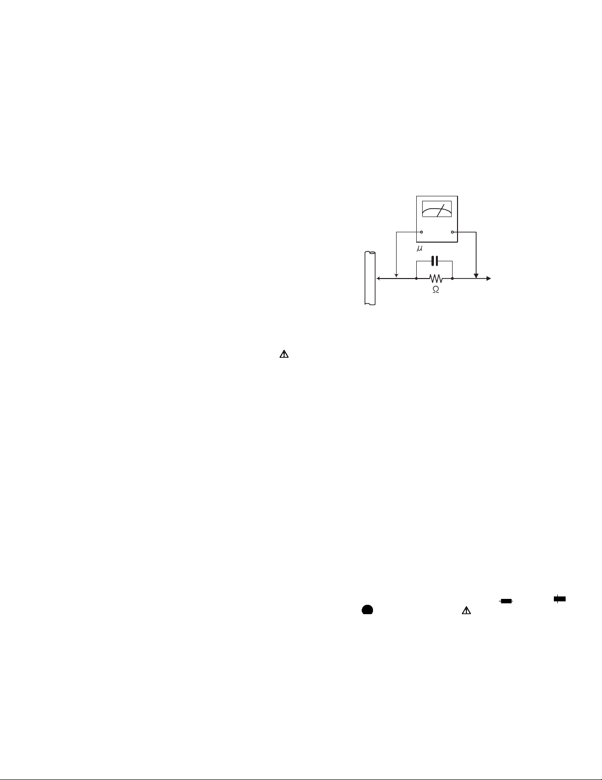
• Alternate check method
Plug the AC line cord directly into the AC outlet. Use an
AC voltmeter having, 1,000Ω per volt or more sensitivity
in the following manner. Connect a 1,500Ω 10W resistor
paralleled by a 0.15µF AC-type capacitor between an exposed metal part and a known good earth ground.
Measure the AC voltage across the resistor with the AC
voltmeter.
Move the resistor connection to each exposed metal
part, particularly any exposed metal part having a return
path to the chassis, and measure the AC voltage across
the resistor. Now, reverse the plug in the AC outlet and
repeat each measurement. Voltage measured any must
not exceed 0.75 V AC (r.m.s.). This corresponds to 0.5
mA AC (r.m.s.).
AC VOLTMETER
(Having 1000
ohms/volts,
or more sensitivity)
0.15 F AC TYPE
Place this
probe on
Good earth ground
1.2 Warning
(1) This equipment has been designed and manufactured to
meet international safety standards.
(2) It is the legal resp onsibility of the repairer to ensure that
these safety standards are maintained.
(3) Repairs must be made in accordance with the relevant
safety standards.
(4) It is essential that safety critical compone nts are replaced
by approved parts.
(5) If mains voltage selector is provided, check setting for local
voltage.
1.3 Caution Burrs formed during molding may be left over on some parts
of the chassis.
Therefore, pay attention to such burrs in the case of preforming repair of this system.
1.4 Critical parts for safety
In regard with component parts appearing on the silk-screen
printed side (parts side) of the PWB diagrams, the parts that are
printed over with black such as the resistor ( ), diode ( )
and ICP ( ) or identified by the " " mark nearby are critical
for safety. When replacing them, be sure to use the parts of the
same type and rating as specified by the manufacturer.
(This regulation dose not Except the J and C version)
each exposed
metal part.
(No.MB128)1-3
Page 4

1.5 Safety Precautions (U.K only)
(1) This design of this product contains special hardware and many circuits and components specially for safety purposes. For con-
tinued protection, no changes should be made to the original design unless authorized in writing by the manufacturer. Replacement parts must be identical to those used in the original circuits.
(2) Any unauthorised design alterations or additions will void the manufacturer's guara ntee; furthermore the manu facturer cannot
accept responsibility for personal injury or property damage resulting therefrom.
(3) Essential safety critical components are identified by ( ) on the Parts List and by shading on the schematics, and must never
be replaced by parts other than those listed in the man ual. Please note however that many el ectrical and mechanical parts in
the product have special safety related characteristics. These characteristics are often not evident from visual inspection. Parts
other than specified by the manufacturer may not have the same safety characteristics as the recommended replacement parts
shown in the Parts List of the Service Manual and may create shock, fire, or other hazards.
(4) The leads in the products are routed and dressed with ties, clamps, tubings, barriers and the like to be separated from live parts,
high temperature parts, moving parts and/or sharp edges for the prevention of electric sh ock and fire ha zard. When se rvice is
required, the original lead routing and dress should be observed, and it should be confi rmed that they have been returned to
normal, after re-assembling.
1.5.1 W arning
(1) Service should be performed by qualified personnel only.
(2) This equipment has been designed and manufactured to meet international safety standards.
(3) It is the legal responsibility of the repairer to ensure that these safety standards are maintained.
(4) Repairs must be made in accordance with the relevant safety standards.
(5) It is essential that safety critical components are replaced by approved parts.
(6) If mains voltage selector is provided, check setting for local voltage.
Burrs formed during molding may be left over on some parts of the chassis. Therefore,
pay attention to such burrs in the case of preforming repair of this system.
1-4 (No.MB128)
Page 5
1.6 Preventing static electricity
Electrostatic discharge (ESD), which occurs when static electricity stored in the body, fabric, etc. is discharged, can destroy the laser
diode in the traverse unit (optical pickup). Take care to prevent this when performing repairs.
1.6.1 Grounding to prevent damage by static electricity
Static electricity in the work area can destroy the optical pickup (laser diode) in devices such as DVD players.
Be careful to use proper grounding in the area where repairs are being performed.
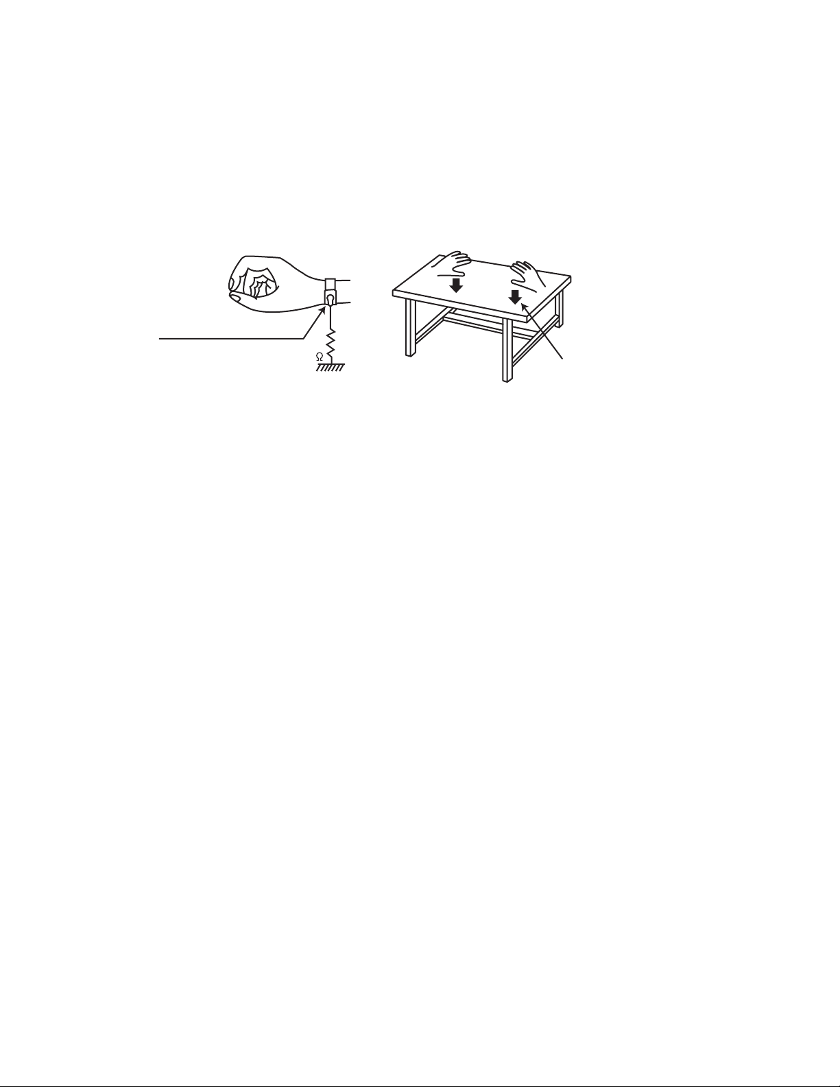
(1) Ground the workbench
Ground the workbench by laying conductive material (such as a conducti ve sheet) or an iron plate over it before placing the
traverse unit (optical pickup) on it.
(2) Ground yourself
Use an anti-static wrist strap to release any static electricity built up in your body.
(caption)
Anti-static wrist strap
1M
Conductive material
(conductive sheet) or iron palate
(3) Handling the optical pickup
• In order to maintain quali ty during transport and before insta llation, both sides of the la ser diode on the replacemen t optical
pickup are shorted. After replacement, return the shorted parts to their original condition.
(Refer to the text.)
• Do not use a tester to check the condition of the laser diode in the optical pickup. The tester's internal power source can easily
destroy the laser diode.
1.7 Handling the traverse unit (optical pickup)
(1) Do not subject the traverse unit (optical pickup) to strong shocks, as it is a sensitive, complex unit.
(2) Cut off the shorted part of the flexible cable using nippers, etc. after replacing the optical pickup. For specific details, refer to the
replacement procedure in the text. Remove the anti-static pin when replacing the traverse unit. Be careful not to take too long
a time when attaching it to the connector.
(3) Handle the flexible cable carefully as it may break when subjected to strong force.
(4) I t is not possible to adjust the semi-fixed resistor that adjusts the laser power. Do not turn it.
1.8 Attention when traverse unit is decomposed *Please refer to "Disassembly method" in the text for the DVD pickup unit.
• Apply solder to the short land sections before the flexible wire is disconn ected from the con nector on the DVD servo board. (If the
flexible wire is disconnected without applying solder, the DVD pickup may be destroyed by static electricity.)
• In the assembly, be sure to remove solder from the short land sections after connecting the flexible wire.
(No.MB128)1-5
Page 6
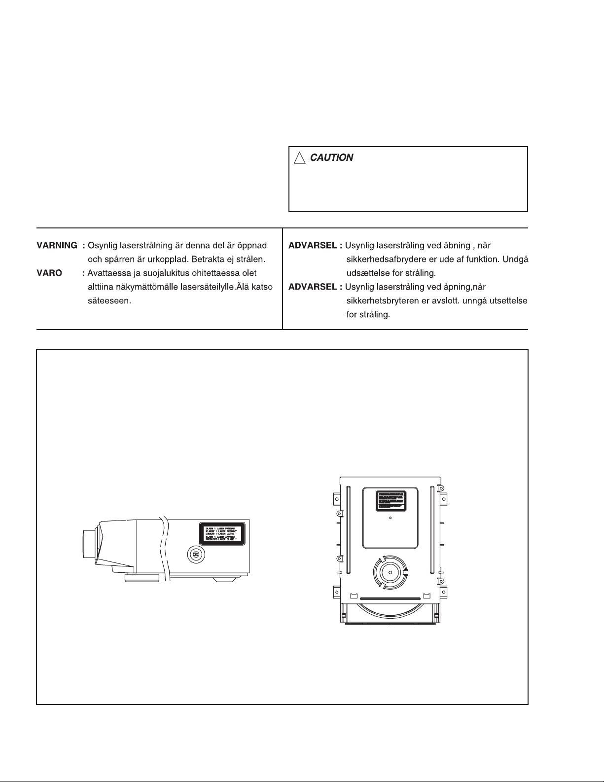
1.9 Important for laser products
1.CLASS 1 LASER PRODUCT
2.DANGER : Invisible laser radiation when open and inter
lock failed or defeated. Avoid direct exposure to beam.
3.CAUTION : There are no serviceable parts inside the
Laser Unit. Do not disassemble the Laser Unit. Replace
the complete Laser Unit if it malfunctions.
4.CAUTION : The compact disc player uses invisible laser
radiation and is equipped with safety switches which
prevent emission of radiation when the drawer is open and
the safety interlocks have failed or are de
feated. It is dangerous to defeat the safety switches.
5.CAUTION : If safety switches malfunction, the laser is able
to function.
6.CAUTION : Use of controls, adjustments or performance of
procedures other than those specified herein may result in
hazardous radiation exposure.
!
Please use enough caution not to
see the beam directly or touch it
in case of an adjustment or operation
check.
REPRODUCTION AND POSITION OF LABEL and PRINT
WARNING LABEL and PRINT
1-6 (No.MB128)
Page 7

SECTION 2
SPECIFIC SERVICE INSTRUCTIONS
This service manual does not describe SPECIFIC SERVICE INSTRUCTIONS.
(No.MB128)1-7
Page 8
SECTION 3
DISASSEMBLY
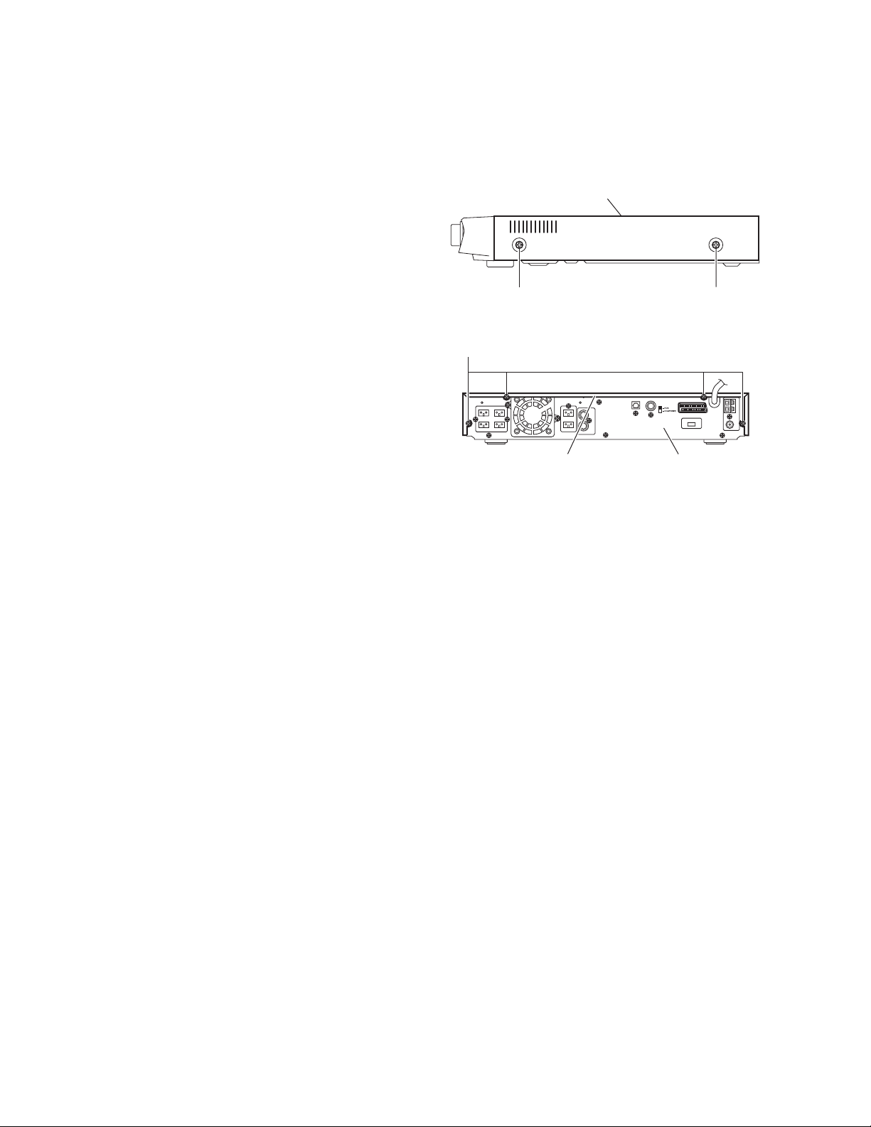
3.1 Main body section
3.1.1 R emoving the top cover
(See Figs.1 and 2)
(1) From the both sides of the main body, remove the four
screws A attaching the top cover. (See Fig.1)
(2) From the back side of the main body, remove the four
screws B attaching the top cover. (See Fig.2)
(3) Take out the top cover in the upward direction while ex-
tending the lower sections of the top cover in the direction
of right and left.
Top cover
AA
Fig.1
B
Top cover Rear panel
Fig.2
1-8 (No.MB128)
Page 9
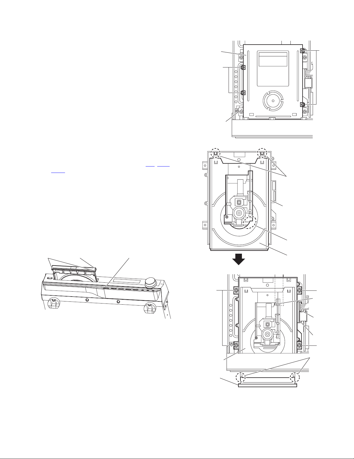
3.1.2 Removing the tray door
(See Figs.3 to 6)
• Prior to performing the follow ing procedures, remove the top
cover.
• The following pr ocedures are performe d in the case of power
on.
(1) From the front side of the main body, push the disk open
bottom and eject the disc tray. (See Fig.3)
(2) Release the joints a in the upward dire ction and take out
the tray door. (See Fig.3)
NOTE:
The following procedures are performed in the case of power
off.
(1) From the top side of the main body, remove the four
screws C attaching the DVD top cover. (See Fig.4)
(2) Take out the disc tray in the directi on of the arrow whi le
lifting the section b. (See Fig.5)
(3) Release the joints a in an upward direction and take out
the tray door. (See Fig.6)
(4) Remove the four screws D attaching the DVD mecha-
nism assembly. (See Fig.6)
(5) Disconnect the wires from the connectors AJ1
on the DVD mechanism assembly, and take out
PCN1
the DVD mechanism assembly. (See Fig.6)
(6) Push in the disc tray while lifting the section b. (See
Fig.5)
Reference:
• When pushing in the disc tray, push it until the position of the claw c. (See Fig.5)
(7) Attach the DVD top cover with the four screws C to the
DVD mechanism assembly.
Reference:
• Attaching method of the DVD mechanism assembly
refers to the section 3.1.3.
Joints a Disk open buttonTray door
, AJS1 and
DVD
top cover
C
DVD
mechanism
assembly
C
Fig.4
Claws c
DVD mechanism
assembly
Section b
Disk tray
Fig.3
D
DVD
mechanism
assembly
Tray door
Fig.5
D
AJ1
PCN1
AJS1
D
Joints a
Fig.6
(No.MB128)1-9
Page 10

3.1.3 Removing the DVD mechanism assembly
(See Fig.7)
• Prior to performing the following procedures, remove the top
cover and tray door.
(1) From the top side of the main body, remove the four screws
D attaching the DVD mechanism assembly.
(2) Disconnect the wires from the conn ectors AJ1
PCN1 on the DVD mechanism assembly, and take out the
DVD mechanism assembly.
, AJS1 and
D
D
JS1
PCN1
AJS1
3.1.4 R emoving the front panel assembly (See Figs.8 and 9)
• Prior to performing the following procedures, remove the top
cover and tray door.
(1) From the top side of the main bod y, disconnect the card
wire from the connector UW4
Fig.8)
(2) From the bottom side of the main body, remove the four
screws E attaching the front panel assembly. (See Fig.9)
(3) From the both sides of the main body, remove the two
screws F attaching the front panel assembly. (See Fig.9)
(4) Release the joints d in fo rward direction and take out the
front panel assembly. (See Fig.9)
3.1.5 Removing the tuner pack
(See Figs.8 and 10)
• Prior to performing the following procedures, remove the top
cover.
(1) From the top side of the main bod y, disconnect the card
wire from the connector VW4
(2) Remove the screw G attaching the tuner pack. (See Fig.8)
(3) From the back side of the main body, remove the screw H
attaching the tuner pack. (See Fig.10)
on the function board. (See
on video board. (See Fig.8)
DVD
mechanism
assembly
E
Front panel assembly
Fig.7
Front panel assembly
Fig.8
UW4
D
F
Joint d
3.1.6 Removing the fan motor (See Figs.8 and 10)
• Prior to performing the following procedures, remove the top
cover.
(1) From the top side of the main body, disconnect the fan
motor wire from the connector UW9
(See Fig.8)
(2) From the back side of the main body, remove two screws J
attaching the fan motor. (See Fig.10)
1-10 (No.MB128)
on the function board.
Fan motor
J H
UW9
Fan motor
Video board
Fig.9
Rear panel
Fig.10
Function
board
G
Tuner
pack
VW4
Page 11

3.1.7 Removing the rear panel
(See Fig.11)
• Prior to performing the follow ing procedures, remove the top
cover and fan motor.
(1) From the back side of the main body, remove the p ower
cord from the rear panel in the direction of the arrow.
(2) Remove the screw H, two screws K, five screws L three
screws M and attaching the rear panel.
(3) Take out the rear panel.
L
Rear panel
K
Power cord
3.1.8 Removing the video board
(See Fig.12)
• Prior to performing the follow ing procedures, remove the top
cover, fan motor and rear panel.
(1) From the top side of the main body, disconnect the power
cord from the connector ACW1
(2) Disconnect the card wire from th e connector VW4
video board.
(3) Disconnect the video board from the connector UW7
on the function board, and turn over the video board.
UW8
(4) From the reverse side of the video board, disconnect the
card wire from the connector VW3
take out the video board.
Reference:
• Remove the tie band as required.
3.1.9 Removing the function board
(See Fig.13)
• Prior to performing the follow ing procedures, remove the top
cover, fan motor, rear panel and video board.
(1) From the top side of the ma in body, disconnect the wires
from the connector PCN1
assembly.
(2) Disconnect the card wire from the connector UW4
on the function board.
UW6
(3) Remove the screw N attaching the function board.
(4) Disconnect the function board from the connector CW5
and CW7 on the main board.
CW6
on the main board.
on the
and
on the video board, and
on the DVD mechanism
and
M
Fig.11
Function board
Video board
,
VW3 VW4
Fig.12
UW4UW6 DVD mechanism
PCN1
H
UW7
UW8
ACW1
Tie band
Power cord
assembly
N
CW5
CW6
CW7
Main boardFunction board
Fig.13
(No.MB128)1-11
Page 12

3.1.10 Removing the main board
A
A
A
(See Fig.14)
• Prior to performing the following procedures, remove the top
cover, tray door, DVD mechanism assembly, fan motor, rear
panel, video board and function board.
(1) From the top side of the main body, remove the nine
screws P attaching the main board.
(2) Disconnect the wires from the connectors ACW2
and ACW5 on the main board and take out the main
ACW4
board.
Reference:
• When attaching the screw P, attach the wire clamp together
with it.
• After connecting the wire to the connector ACW2
wire using the wire clamp.
3.1.11 Removing the power trans
(See Fig.14)
• Prior to performing the following procedures, remove the top
cover, tray door, DVD mechanism assembly, fan motor, rear
panel, video board and function board.
(1) From the top side of the main body, disconnect the wires
from the connectors ACW2
the main board.
(2) Remove the four screws Q attaching the power trans.
, ACW3, ACW4 and ACW5 on
, ACW3,
, bundle the
Power trans
Q
CW4
P
CW3
CW5
P
P
Q
Fig.14
Wire clamp
ACW2
1-12 (No.MB128)
Page 13

3.2 Front panel assembly section
3.2.1 Removing the front board (See Fig.15)
• Prior to performing the follow ing procedures, remove the top
cover, tray door and front panel assembly.
(1) From the back side of the front panel assembly, remove the
five screws R attaching the FRONT board.
(2) Disconnect the wire from the connector UCW13
front board.
(3) Take out the front board from the front panel assembly.
3.2.2 Removing the power SW board
(See Fig.15)
• Prior to performing the follow ing procedures, remove the top
cover, tray door, front panel assembly and front board.
(1) Remove the screw S attaching the power SW board.
(2) Take out the power SW board from the front panel
assembly.
on the
Front board Power SW boardUCW13
Wire
R S
Fig.15
(No.MB128)1-13
Page 14

SECTION 4
ADJUSTMENT
This service manual does not describe ADJUSTMENT.
1-14 (No.MB128)
Page 15

5.1 MAIN
5.1.1 POWER
SECTION 5
TROUBLESHOOTING
Check for VCC(5V)
FRONT PCB
at
;pin #17,46,72,90 of UIC1
YES
Check for power-sense(5V)at FRONT PCB
;pin #77 of UIC1
YES
When power on for FRONT PCB
Check for High Voltage(5V) at"M"com
74 of UIC1
;pin#
NO
NO
Check for Input voltage
POWER PCB
at
;AIC1(7805)
YES
Replace
Check normal Voltage
at
POWER PCB
AZD1 (5.1V, 1/2W)
YES
Check pattern from VCW7
to pin#77 of UIC1
NO
AIC1
NO
Check for circuit at Sub Trans
;PBD2, PT1, AFS3(Fuse)
Replace AZD1
NO
Check resistant from GND
to pin #77 of MICOM(UIC1)
if the short(0 ohm),to replace
Micom(UIC1)
YES
Check low Voltage(0V)
at
EXPAND IC (M66010)
;pin#32 of UIC500
YES
Check for connector from DSP PCB to FRONT PCB
;VCW7
Replace Micom(UIC1)
NO
If High Voltage (5V), check for Circuit protection
Check connector wire Ass'y of power
P/T - MAIN PCB(7P,ACW3)
MAIN PCB (8P,PW3)
(No.MB128)1-15
Page 16

5.1.2 OUTPUT
Check voltage at Main PCB
; VM, VL
YES
Check Audio channel at CW5
for input:5.1 channel Audio signal
YES
NO
Check Connector PW1
Check ABD2,4
NO
Check Voltage for CW7
; 12V
Check signal for FR/FL/C/W/RL/RR
at MAIN PCB
YES
Check voltage for CW7(SPK Relay)
;High(5V)
Check Q4,Q5
NO
NO
Check circuit for AMP channel
;Out ports of FIC6, IC7, RIC5
Reference to NEXT page
; "A" position
Check circuit for Speak Relay
1-16 (No.MB128)
Page 17

5.1.3 Protection(When High Voltage at Protectiion port)
5.1.3.1 In this case "LOW" for, Base port of Q12(R2003 TR) at MAIN PCB
Check voltage for IC4
-12V
YES
Check Voltage
for Main AMP of Main PCB
VM, VL
YES
"A"
Check DC Voltage for Speaker port
NO
Check circuit for voltage(-12V)
NO
Check ABD2,4
NO
Check circuit for DC Voltage
YES
Check the parts is normal?
;ZD6,ZD5(3.9V)
;R33,R36(27K)
R34,R37 (150 O h m)
YES
Check normal condition for Q15(C945)
;temperature-sense S/W be operated in the Power Trans
is Turn on
YES
Check electric potention for PBD 1, ABD1, PD3 at DVD Power PCB
NO
NO
Replace P/T, Q15
Check circuit for
Diode behind position
(No.MB128)1-17
Page 18

5.1.3.2 In this case "LOW" for Base of Q13(A733) at Main PCB
Check the Turn on for channel of Q35(C945)
Check circuit for channel(Turn on)
according feedback "A"position of
previous page
5.1.3.3 Check the Connector Wire Ass'y Connectin of each PCB
;DVD MECHA - Main PCB (8P,PW3)
;POWER TRANS - Main PCB (ACW3)
1-18 (No.MB128)
Page 19

5.2 DVD Servo parts
5.2.1 Initial operation after power ON
POWER ON
3
4
DVD single or
Dual layer judgement
Is Tray closed?
Y
Pick up headinit ial position.
Disc present or not
Disc present
Y
CD or DVD judgement
DVD
N
CD
Tray close operation.
about 3sec.
Y
Is Tray closed?
Stop Close operation.
Wait Open Command from MPEG
N
Laser Off
Monitor Display=NO DISC
CD or CDRW
judgement
N
Single
DVD single
initial setting
Dual
DVD Dual
initial setting
To Each disc playback
(DVD Dual) (DVD single)
CD CDRW
CD
initial setting
CDRW
initial setting
(No.MB128)1-19
Page 20

5.2.2 Play operation
Play
5
Disc Motor forced accelleration
Repeat
seveal times
Change
Disc Type
Focus Seach
Is focus servo
on?
Track servo ON
CLV servo ON
6
7
8
Automatic Adjustment
Automatic Adjustment is done once
when the disc is replaced
Read TOC
Search Picture appears
1-20 (No.MB128)
Page 21

5.2.3 PickUp Head Initial Position
PickUp Head Initial Position
(1) 1. Move Pick Up Head to inner direction until pin5 of MJ4="L"
(2) 2. If pin5 of MJ4="L", then move Pick Up Head to outer direction for a short time.
(3) 3. Turn On the Laser of Pick Up Head to judge that disc is present or not.
3
OK
Does Pick Up
Move to inner
direction?
Y
Does Pick Up
Move to out
direction again?
Y
Does Laser Turn
On?
N
Is pulse of 2.5
Y
+-2.5V developed
at pin3,4 of MJ4?
Check
connection
between PCB
and MECHA
N
Is pulse of 2.5
+-2.5V developed
at pin13 of SIC1
Y
N
Check
peripheral
circuit of SIC1
and DRIC1
Check BUS
line between
SIC1 and MIC1
N
Is pin5 of MJ4 =
N
"L" appeared?
Check
connection
between PCB
Y
Check line between SIC1
and MJ4
and MECHA
N
Check voltage at
pin8 of RCN1 is
about 2.5V?
N
Check BUS line between RIC1 and
SIC1,SIC1 and MIC1
Y
Replace Pick Up Head
(No.MB128)1-21
Page 22

5.2.4 Disc Presence/Absense Judgment
4
Disc Presence Judgment
Turn On Laser
Does lens move
with UP/DOWN
full stroke in focus
direction?
Y
Check PI
(pin36 of RU1)
signal and FE
(pin42 of RIC1)signal
Normal
Disc is presence
N
Is focus search
voltage developed
at pin 11 of SIC1
N
Check
Y
peripheral
circuit of DRIC1
Check BUS
line between
SIC1 and MIC1
YNo signal
No Disc OK
N
Check connection between RIC1 and RCN1.
Check BUS line RIC1and SIC1.
Check RIC1
1-22 (No.MB128)
Page 23

5.2.5 Disc Motor Does Not Rotate
Disc Motor Does Not Rotate
5
Is Voltage of 0V
developed at
pin15 of SIC1
Check peripheral circuit of SIC1.
Check SIC1
5.2.6 Focus Servo does not Work
Focus Servo does not Work
Are FE(pin42 of RIC1)
and PI(pin36 of RIC1)
normal?
Y
Check peripheral circuit of DRIC1
N
6
N
Check peripheral circuit of SIC1 and
RIC1
Y
Check peripheral circuit of SIC1 and
RIC1
Check peripheral circuit of DRIC1
Check Connection between PCB and
MECHA
(CD-RW)
(DVD Dual)(DVD Single)(CD)
(No.MB128)1-23
Page 24

5.2.7 Tracking Servo Does Not Work
Tracking Servo Does not Work
7
Check Voltage of
PI(pin36 of RIC1) is
normal
Y
Is TE(pin41 of RIC1)
normal?
Y
Check peripheral circuit or RCN1 and
DRIC1
Check connection between PCB
and MECHA
N
Disc Judgment Error
N
Check peripheral circuit or RIC1
Change PickUp or RIC1
Change SIC1
1-24 (No.MB128)
(CD)
(DVD Single) (DVD Dual)
(CD-RW)
Page 25

5.2.8 CLV Servo Does Not Work
CLV Servo Does not Work
8
Y
Is XSRFIN(pin2 of SIC1)
normal?
N
Is RF(pin21 of RCN1)
normal?
N
Check connection between PCB
and MECHA
Check peripheral circuit of SIC1
Check peripheral circuit of DRIC1
Y
Check peripheral circuit of RIC1
(No.MB128)1-25
Page 26

5.3 DVD MPEG Parts
5.3.1 Initial operation after NO
POWER ON
WAIT
N
2
LOGO ON
N
Check Reset Voltage at 24pin of
U13
Y
"NO DISC" DISPLAY
(in time of absence)
N
Check Servo parts and MPEG
ATAPI Line
Y
Loading
(in time of presence)
N
Check Servo spindle motor
parts
Y
Play
Y
Audio out/ in
normal
Y
OK
N
Check
Pick up Lens and Pick up Flat
Cable
N
3
1-26 (No.MB128)
Page 27

5.3.2 Logo operation
2
Fig.1
5.3.3 Audio operation
Check 27MHZ crystal
FIg.1
Check 114MHZ(pin 102
of U13)
Video OK
OK
3
Check Voltage
of REG2 2.85V
REG3 3.50V
Y
Y
N
Check Video signal of
VQ1,VQ3,VQ4,VQ5,VQ6
Y
Check Audio Digital signal
at pin 33,36,37 of U13
Y
Audio out
Y
OK
N
Check NEW DSP Parts
N
Check Main AMP parts
(No.MB128)1-27
Page 28

VICTOR COMPANY OF JAPAN, LIMITED
AV & MULTIMEDIA COMPANY AUDIO/VIDEO SYSTEMS CATEGORY 10-1,1chome,Ohwatari-machi,Maebashi-city,371-8543,Japan
(No.MB128)
Printed in Japan
WPC
 Loading...