

Page 1
SPEAKER SYSTEM
ENCEINTE ACOUSTIQUE
SX-WD8
EnglishFrançais
INSTRUCTIONS
MANUEL D’INSTRUCTIONS
For Customer Use:
Enter below the Model No. and Serial
No. which are located either on the rear,
bottom or side of the cabinet. Retain this
information for future reference.
Model No.
Serial No.
LVT1293-006A
[J]
Page 2
Warnings, Cautions and Others
Preparation
7 Precautions for installation
English
• Do not install the speakers on an uneven surface or in a place
subject to vibration; otherwise, they may fall over, causing
damage or injury.
– Take the occurrence of earthquakes or other physical
shocks into consideration when selecting the installation
place, and secure the speakers thoroughly.
• To prevent deformation or discoloration of the cabinet, do not
install the speakers where they are exposed to direct sunlight
or high humidity, and avoid installation near air conditioning
outlets.
• Speaker vibrations may cause howling. Place the speakers as
far away from the player as possible.
• The speakers are magnetically shielded to avoid color
distortions on TVs. However, if not installed properly, it may
cause color distortions. So, pay attention to the following when
installing the speakers.
– When placing the speakers near a TV set, turn off the TV’s
main power switch or unplug it before installing the
speakers.
Then wait at least 30 minutes before turning on the TV’s
main power switch again.
Some TVs may still be affected even though you have followed
the above.
If this happens, move the speakers further away from the TV.
• Tuner reception may become noisy or hissing if a speaker is
installed near the tuner.
In this case, leave more distance between the tuner and the
speakers or use an outdoor antenna for better tuner reception
without interference from the speakers.
7 Precautions for daily use
• To maintain the appearance of the speakers
– Wipe with a dry, soft cloth if the cabinet should become
dirty.
If very dirty, wipe with a cloth applied a small amount of
water or neutral detergent, then wipe with a dry cloth.
– Do not use chemicals such as benzine and thinner for
cleaning the cabinet.
• To improve the sound field
– It is recommended to leave a space of more than 50 cm
between the speakers and the wall.
– If the speakers are facing a solid wall or glass door, etc., it is
recommended to furnish the wall with materials that absorb
sounds, for example by hanging up thick curtains, to prevent
reflections and standing waves.
• To use the speakers without any trouble
– Do not reproduce sounds at so high a volume that they are
distorted; otherwise, the speakers may be damaged by
internal heat buildup.
– When moving the speakers, do not pull the speaker cords;
otherwise, the speakers may fall over, causing damage or
injury.
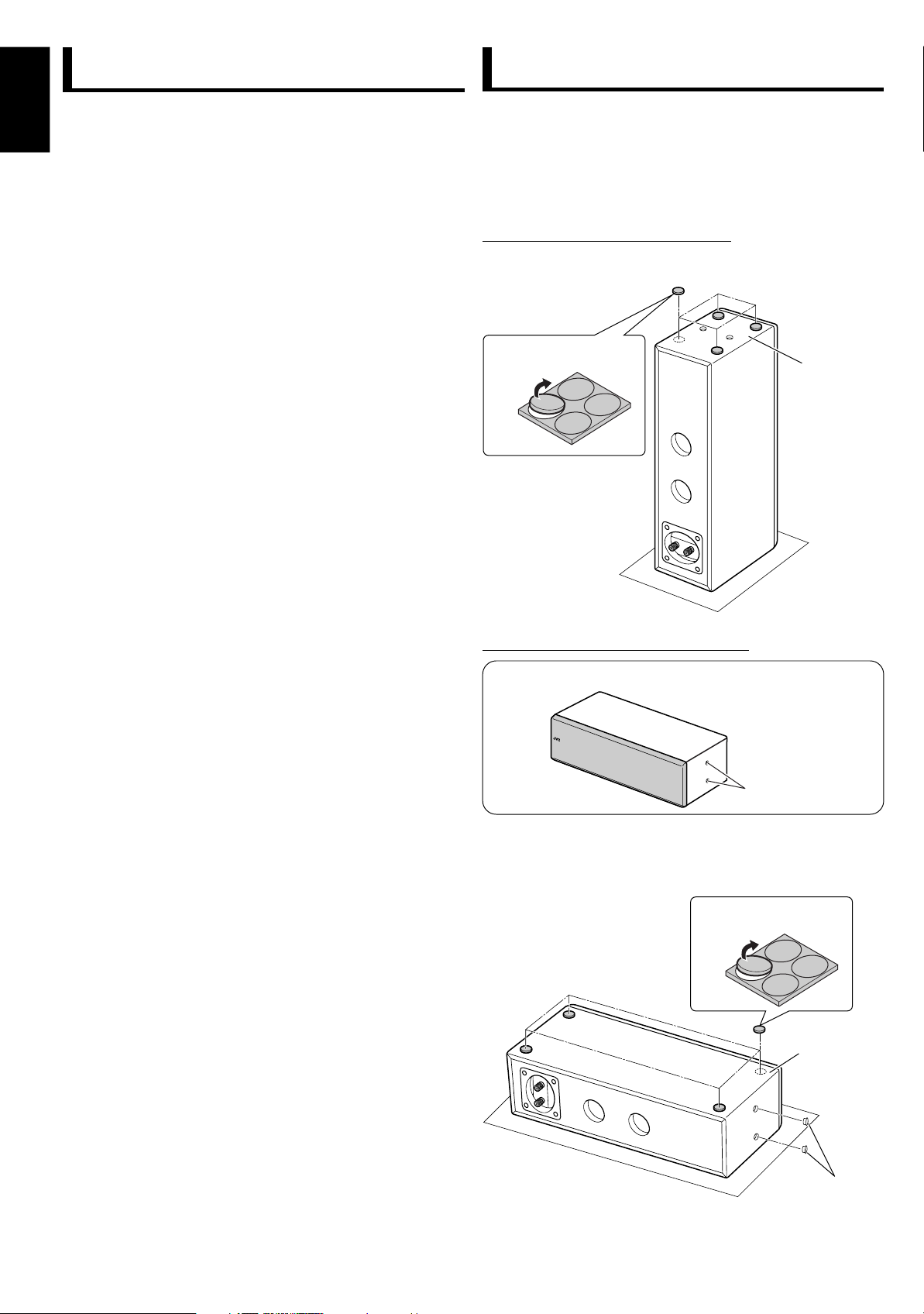
7 Attaching the feet
Attach the supplied feet on the bottom of the speaker, so that you
can protect the speaker cabinet, absorb the speaker vibration,
and prevent the speaker slipping.
• Place a large, thick cloth under the speaker in order to protect
the floor and the speaker.
When installing the speaker vertically
1
Stand the speaker upside down.
2
Attach the feet.
Peel off the feet
When installing the speaker horizontally
Install the speaker with the screw holes facing rightward.
Screw holes
1
Place the speaker with the side, where you attach the feet,
facing upward.
2
Attach the feet.
3
Attach the screw hole caps to the screw holes.
Peel off the feet
Bottom
Bottom
Screw hole caps
2
Page 3
Connection
123
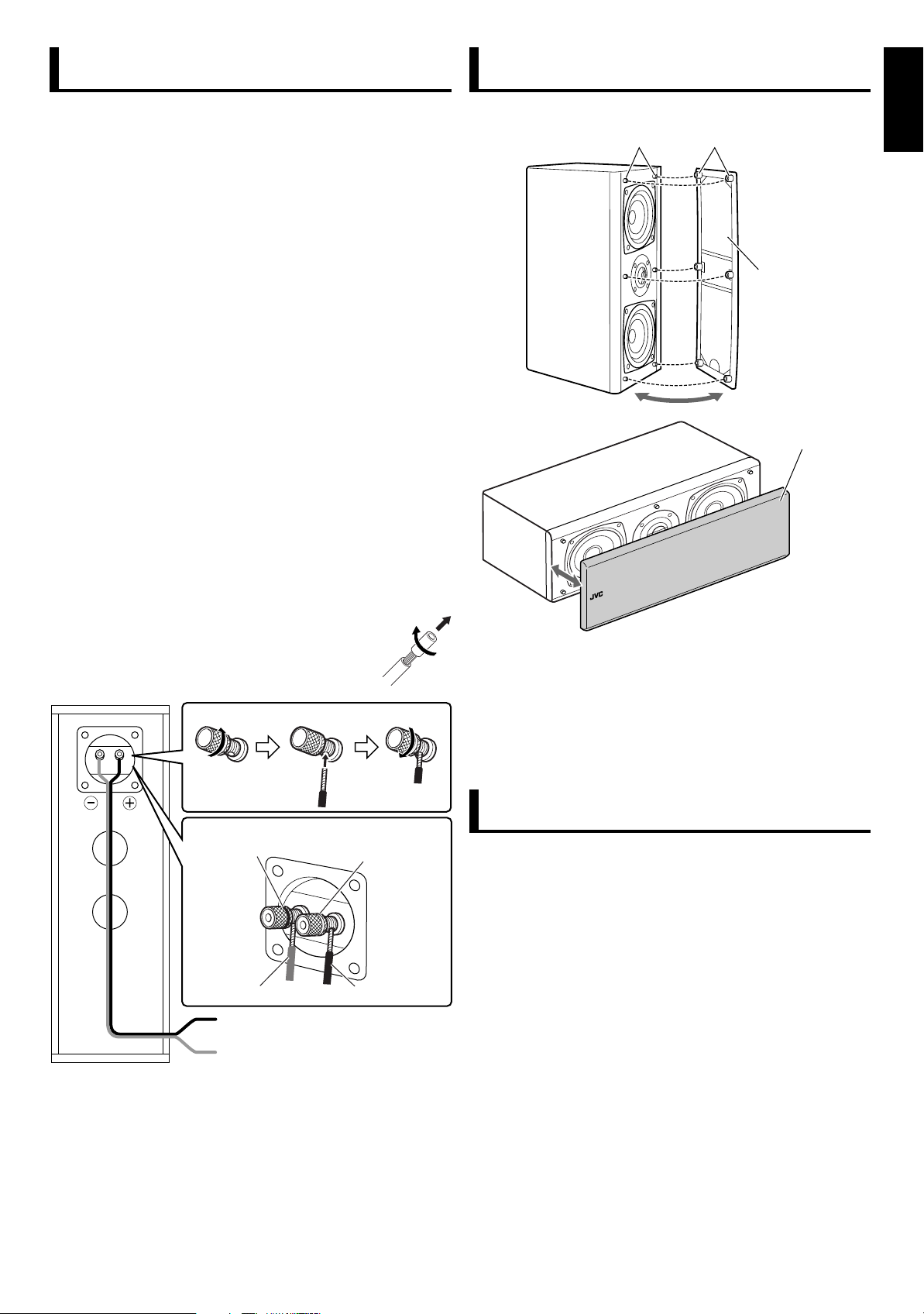
About Speaker Grille
7 Precautions
Before connecting:
• Turn off the power to the amplifier before connecting the
speaker system; otherwise, the speakers may be damaged.
• The impedance of the speaker is 6 Ω.
If this does not match with the speaker impedance range
indicated on the amplifier, you cannot connect this system to
the amplifier.
• The maximum power handling capacity of the SX-WD8 is
150 W. Excessive input will result in abnormal noise and
possible damage.
• Be sure to turn down the volume level on the amplifier to
prevent unwanted noise before performing following
operations:
– Turning on or off other components
– Operating the amplifier
– Tuning FM stations
– Fast-forwarding a tape
– Continuously reproducing high frequency oscillation or high
pitch electronic sounds
– Connecting or disconnecting a microphone
• When using a microphone, do not aim it at the speakers or
use it near the speakers; otherwise, the howling which occurs
may damage the speakers.
• Before replacing the cartridge, always turn off the power both
to the amplifier and to the turntable; otherwise, the clicking
noise may damage the speakers.
The speaker grille is removable as illustrated below:
Projections
Holes
Speaker grille
Speaker grille
English
7 Connecting the speaker system to the amplifier
• Twist and remove the insulation at the end of
each speaker cord before connecting.
· terminal
(Black hoop)
Silver
To the speaker ª terminal of amplifier
To the speaker · terminal of amplifier
• Make sure to match the polarity (ª and ·); otherwise, the
surround effect will become less effective.
ª terminal
(Red hoop)
Copper
To remove the speaker grille, insert your fingers at the top of
the speaker grille, then pull towards you. Repeat the procedure at
the bottom of the speaker grille.
To attach the speaker grille, put the projections of the speaker
into the holes of the speaker grille.
• Do not push the speaker grille strongly.
Specifications
Type: 2-way 3-speaker bass-reflex type
Magnetically-shielded type
Speakers
Mid and low range: 10.5 cm (4
Tweeter: 2.0 cm (
Power handling capacity: 150 W
Impedance: 6 Ω
Crossover frequency: 3 800 Hz
Frequency range: 50 Hz to 50 000 Hz
Sound pressure level: 84.5 dB/W•m
Dimensions (W x H x D): 143 mm x 405 mm x 249 mm
Mass: 6.3 kg (13.9 lbs)
Supplied accessories: • Feet (4)
11
(5
• Speaker cord (3 m) (1)
• Screw hole caps (2)
3
/16 in.) wooden cone
13
/16 in.) wooden dome
/
in. x 16 in. x 9 13/16 in.)
16
Design and specifications subject to change without notice.
3
Page 4

Avertissements, précautions et autres
Préparation
7 Précautions pour l’installation
• N’installez pas les enceintes sur une surface accidentée ou
dans un endroit sujet aux vibrations; sinon, elles risquent de
tomber causant des dommages ou des blessures.
– Lors de la sélection de l’emplacement d’installation des
enceintes prenez aussi en considération les tremblements
de terre ou d’autres chocs physiques, et fixez les en
Français
conséquence.
• Pour éviter la déformation ou la décoloration du boîtier,
n’installez pas les enceintes dans un endroit exposé
directement au soleil ou à une forte humidité, et évitez de les
installer près d’une sortie de climatiseur.
• Les vibrations des enceintes peuvent causer des hurlements.
Placez-les aussi loin que possible du lecteur.
• Les enceintes sont blindées magnétiquement pour éviter toute
distorsion des couleurs sur les téléviseurs. Cependant, si elles
ne sont pas installées correctement, elles peuvent causer des
distorsions des couleurs. Faites attention aux points suivants
lors de l’installation des enceintes.
– Lors de l’installation des enceintes près d’un téléviseur,
mettez le téléviseur hors tension ou débranchez-le avant
d’installer les enceintes.
Attendez ensuite 30 minutes avant de remettre le téléviseur
sous tension.
Certains téléviseurs peuvent quand même être affectés même
si vous avez suivi les points ci-dessus.
Si cela se produit, éloigné les enceintes du téléviseur.
• La réception du tuner peut devenir parasitée ou des
sifflements peuvent se produire si une enceinte est installée
près du tuner.
Dans ce cas, éloigné un peu plus le tuner de l’enceinte ou
utilisez une antenne extérieure pour obtenir une meilleure
réception du tuner sans interférence des enceintes.
7 Fixation des pieds
Attachez les pieds fournis au-dessous de l’enceinte de façon à
protéger le boîtier de l’enceinte, d’absorber les vibrations et de
l’empêcher de glisser.
• Placez un grand tissu épais sous l’enceinte pour protéger le
sol et l’enceinte.
Lors de l’installation de l’enceinte verticalement
1
Mettez l’enceinte à l’envers.
2
Fixez les pieds.
Décollez les pieds.
Lors de l’installation des enceintes horizontalement
Placez l’enceinte avec les trous de vis dirigés vers la droite.
Dessous de
l’enceinte
7 Précautions pour une utilisation quotidienne
• Pour conserver l’apparence des enceintes
– Frottez le boîtier avec un chiffon sec et doux s’il est sale.
S’il est très sale, frottez-le avec un chiffon imprégné d’une
petite quantité de détergent neutre, puis essuyez avec un
chiffon sec.
– N’utilisez pas de produits chimiques tels que la benzine ou
des diluants pour nettoyer le boîtier.
• Amélioration du champ acoustique
– Il est recommandé de laisser un espace d’au moins 50 cm
entre les enceintes et le mur.
– Si les enceintes font face à un mur solide ou à une porte
vitrée, etc., il est recommandé de recouvrir le mur de
matériaux absorbant le son, comme par exemple en
suspendant des rideaux épais, afin d’éviter les réflexions et
les ondes stationnaires.
• Pour utiliser les enceintes sans aucun problème
– Ne reproduisez pas des sons à un volume si élevé qu’ils
sont déformés; sinon, les enceintes peuvent être
endommagées par un échauffement interne.
– Lors du déplacement des enceintes, ne tirez pas sur les
cordons d’enceinte; sinon, les enceintes risquent de tomber
et de causer des dommages ou des blessures.
Trous de vis
1
Placez l’enceinte avec la face sur laquelle vous souhaitez
fixer les pieds, dirigée vers le haut.
2
Fixez les pieds.
3
Fixez les caches de trou de vis sur les trous de vis.
Décollez les pieds.
Dessous de
l’enceinte
Caches de trou de vis
4
Page 5

Connexions
123
À propos de la grille de l’enceinte
7 Précautions
Avant la connexion:
• Mettez l’amplificateur hors tension avant de connecter le système
d’enceinte; sinon les enceintes risquent d’être endommagées.
• L’impédance de l'enceinte est de 6 Ω.
Si cela ne correspond pas avec la plage d’impédance
d’enceinte indiquée sur l’amplificateur, vous ne pouvez pas
connecter ce système à l’amplificateur.
• La capacité de puissance soutenue maximale du SX-WD8 est
de 150 W. Un niveau d’entrée excessif peut entraîner des
bruits anormaux et d’éventuels dommages.
• Assurez-vous de réduire le niveau de volume sur
l’amplificateur pour éviter que du bruit indésirable ne soit
produit pendant les opérations suivantes:
– Mise sous ou hors tension des autres appareils
– Utilisation de l’amplificateur
– Accord des stations FM
– Avance rapide d’une bande
– Reproduction continue d’oscillation à haute fréquence ou de
sons électroniques très hauts
– Lors de la connexion ou déconnexion d’un microphone
• Lors de l’utilisation d’un microphone, ne le dirigez pas vers les
enceintes ni ne l’utilisez près des enceintes; sinon, un hurlement
risquerait de se produire et d’endommager les enceintes.
• Avant de remplacer la cellule, coupez toujours le son sur
l’amplificateur et sur le tourne-disque; sinon, le bruit de
craquement peut endommager les enceintes.
La grille de l’enceinte peut être retirée comme montré sur l’illustration.
Bossages
Trous
Grille de l’enceinte
Grille de l’enceinte
Français
7 Connexion du système d’enceinte à
l’amplificateur
• Torsadez et retirez l’isolant à l’extrémité de
chaque cordon d’enceinte avant la connexion.
Prise ·
(vis noire)
Argent
À la prise d’enceinte ª de l’amplificateur
À la prise d’enceinte · de l’amplificateur
• Assurez-vous de respecter les polarités (ª et ·); sinon,
l’effet Surround sera moins fort.
Prise ª
(vis rouge)
Cuivre
Pour retirer la grille de l’enceinte, insérez vos doigts en haut
de la grille, puis tirez vers vous. Répétez cette procédure en bas
de la grille de l’enceinte.
Pour attacher la grille de l’enceinte, insérez les bossages de
l’enceinte dans les trous de la grille.
• Ne poussez pas trop fort sur la grille de l’enceinte.
Spécifications
Type: Enceinte acoustique à évent
accordé à 2 voies et 3 hautparleurs, blindé
magnétiquement
Haut-parleurs
Plage des médiums et des graves:
Haut-parleur d’aigus: 2,0 cm (13/16 pouces) wooden
Capacité de puissance soutenue:
Impédance: 6 Ω
Fréquence de transition: 3 800 Hz
Plage de fréquences: 50 Hz à 50 000 Hz
Niveau de pression acoustique: 84,5 dB/W•m
Dimensions (L x H x P): 143 mm x 405 mm x 249 mm
Masse: 6,3 kg (13.9 livres)
Accessoires fournis: • Pieds (4)
10,5 cm (4 3/16 pouces)
wooden cone
dome
150 W
11
/
pouces x 16 pouces x
(5
16
13
/16 pouces)
9
• Cordon d’enceinte (3 m) (1)
• Caches de trou de vis (2)
La conception et les spécifications sont sujettes à changement
sans notification.
5
Page 6

LIMITED WARRANTY
JVC COMPANY OF AMERICA (JVC) warrants this product and all parts thereof, except as set forth below ONLY TO
THE ORIGINAL RETAIL PURCHASER to be FREE FROM DEFECTIVE MATERIALS AND WORKMANSHIP from the
date of original purchase for the period as shown below. (”The Warranty Period”)
PARTS LABOR
THIS LIMITED WARRANTY IS VALID ONLY IN THE FIFTY (50) UNITED STATES, THE DISTRICT OF COLUMBIA
AND IN THE COMMONWEALTH OF PUERTO RICO.
WHAT WE WILL DO:
If this product is found to be defective within the warranty period, JVC will repair or replace defective parts with new or rebuilt
equivalents at no charge to the original owner. Such repair and replacement services shall be rendered by JVC during normal
business hours at JVC authorized service centers. Parts used for replacement are warranted only for the remainder of the
Warranty Period. All products may be brought to a JVC authorized service center on a carry-in basis. Color television with a
screen size of 27" and or greater qualify for in-home service. In such cases, a technician will come to your home and either
repair the TV there or remove and return it if it cannot be repaired in your home.
WHAT YOU MUST DO FOR WARRANTY SERVICE:
Please do not return your product to the retailer
Instead, return your product to a JVC authorized service center nearest you. If shipping the product to the service
center, please be sure to package it carefully, preferably in the original packaging, and include a brief description of
the problem(s). Please call 1-800-252-5722 to locate the nearest JVC authorized service center. Service locations can
also be obtained from our website http:www.jvc.com. If your product qualifies for in-home service, the service
representative will require clear access to the product.
If you have any questions concerning your Product, please contact our Customer Relations Department at 800-252-5722.
WHAT IS NOT COVERED:
This limited warranty provided by JVC does not cover:
1.
Products which have been subject to abuse, accident, alteration, modification, tampering, negligence, misuse, faulty
installation, lack of reasonable care, or if repaired or serviced by anyone other than a service facility authorized by JVC
to render such service, or if affixed to any attachment not provided with the products, or if the model or serial number
has been altered, tampered with, defaced or removed;
2.
Initial installation and installation and removal from cabinets or mounting systems;
3.
Operational adjustments covered in the Owner’s Manual, normal maintenance, video and audio head cleaning;
4.
Damage that occurs in shipment, due to act of God, and cosmetic damage;
5.
Signal reception problems and failures due to line power surge;
6.
Video Pick-up Tubes/CCD Image Sensors are covered for 90 days from the date of purchase;
Accessories;
7.
8.
Batteries (except that Rechargeable Batteries are covered for 90 days from the date of purchase);
Products used for commercial purposes, including, but not limited to rental.
9.
There are no express warranties except as listed above.
THE DURATION OF ANY IMPLIED WARRANTIES, INCLUDING THE IMPLIED WARRANTY OF MERCHANTABILITY, IS
LIMITED TO THE DURATION OF THE EXPRESS WARRANTY HEREIN.
JVC SHALL NO T BE LIABLE FOR THE LOSS OF USE OF THE PRODUC T, INCONVENIENCE, OR ANY OTHER
DAMAGES, WHETHER DIRECT, INCIDENTAL OR CONSEQUENTIAL (INCLUDING, WITHOUT LIMITATION, DAMAGE TO
TAPES, RECORDS OR DISCS) RESULTING FROM THE USE OF THIS PRODUCT, OR ARISING OUT OF ANY BREACH
OF T H I S WARRANT Y . AL L EX PRESS A N D IM PLIED W A R R ANTIES, IN C L U D ING T H E WA R R ANTIES OF
MERCHANTABILITY AND FITNESS FOR PARTICULAR PURPOSE, ARE LIMITED TO THE WARRANTY PERIOD SET
FORTH ABOVE.
Some states do not allow the exclusion of incidental or consequential damages or limitations on how long an implied warranty
lasts, so these limitations or exclusions may not apply to you. This warranty gives you specific legal rights and you may also
have other rights which vary from state to state.
JVC COMPANY OF AMERICA
DIVISION OF JVC AMERICAS CORP.
1
YR
Wayne, New Jersey 07470
http:www.jvc.com
1
YR
1700 Valley Road
AUDIO-1
REFURBISHED PRODUCTS CARRY A SEPARATE WARRANTY, THIS WARRANTY DOES NOT APPLY. FOR DETAILS
OF REFURBISHE D PRODUC T WARRANTY, PL EASE REFER TO THE REFU RBISHED PRODUCT WARRANTY
INFORMATION PACKAGED WITH EACH REFURBISHED PRODUCT.
For customer use:
Enter below the Model No. which is located either on the rear, bottom or side of the cabinet. Retain this information for future
reference.
Model No. : Serial No. :
Page 7

Page 8

SX-WD8
SPEAKER SYSTEM
EN, FR
0405NSMMAMHCE© 2005 Victor Company of Japan, Limited
 Loading...