

Page 1
R
SR-9240E/EK VIDEO CASSETTE RECORDER
VIDEO CASSETTE RECORDER
INTRODUCTION
CONTROLS AND
CONNECTORS
CONNECTIONS
MONITOR
ON-SCREEN
DISPLAY
SR-9240E
SR-9240EK
REC
REVERSE
STOP/EJECT
PAUSE/
STILL
PAL
CHECK
PLAY
FFREW
REC
VIDEO CASSETTE RECORDER
COUNT/
CLOCK
TIME
MODE
MENU
TIMER
REC
SHIFT/TRACKING
SET/V.LOCK
RESET
/CANCEL
AL/PL
RESET
INSTRUCTIONS
SR-9240E
OPERATE
OPE. LOCK
PAL
SETTING OF THE
FUNCTION MENU
SWITCHES
PREPARATION
RECORDING
PLAYBACK AND
SPECIAL-EFFECTS
PLAYBACK
TROUBLE-
SHOOTING
Thank you for purchasing this JVC product.
Before operating this unit, please read
the instructions carefully to ensure the
best possible performance.
This instruction book is made from
100% recycled paper.
SL96166
OPTIONAL SA-K97U
RS-232C
INTERFACE BOARD
APPENDIXES
Page 2

SAFETY PRECAUTIONS
Warning Notice
FOR YOUR SAFETY (Australia)
1.Insert this plug only into effectively earthed threepin power outlet.
2.If any doubt exists regarding the earthing, consult
a qualified electrician.
3. Extension cord, if used, must be three-core
correctly wired.
IMPORTANT
Connection to the mains supply in the United Kingdom.
DO NOT cut off the mains plug from this equipment.
If the plug fitted is not suitable for the power points in
your home or the cable is too short to reach a power
point, then obtain a proper safety approved extension
lead/adapter or consult your dealer.
BE SURE to replace the fuse only with an identical
approved type, as originally fitted, and to replace the
fuse cover.
If nonetheless the mains plug is cut off remove the
fuse and dispose of the plug immediately, to avoid a
possible shock hazard by inadvertent connection to
the mains supply.
If this product is not supplied fitted with a mains plug
then follow the instructions given below:
DO NOT make any connection to the Larger Terminal
coded E or Green.
The wires in the mains lead are coloured in accordance
with the following code:
POWER SYSTEM
Connection to the mains supply
This unit operates on voltages of 220 to 240 V AC, 50/
60 Hz.
WARNING:
TO PREVENT FIRE OR SHOCK HAZARD, DO
NOT EXPOSE THIS APPLIANCE TO RAIN OR
MOISTURE.
CAUTION
To prevent electric shock, do not open the cabinet. No
user serviceable parts inside. Refer servicing to qualified
service personnel.
Note:
The rating plate and the safety caution are on the rear
of the unit.
The OPERATE button does not completely shut off
mains power from the unit, but switches operating
current on and off.
Notes on the built-in lithium battery
Blue to N (Neutral) or Black
Brown to L (Live) or Red
If these colours do not correspond with the terminal
identifications of your plug, connect as follows:
Blue wire to terminal coded N (Neutral) or coloured
Black.
Brown wire to terminal coded L (Live) or coloured Red.
If in doubt — consult a competent electrician.
CAUTION
When you are not using the recorder for a long
period of time, it is recommended that you
disconnect the power cord from the mains outlet.
Dangerous voltage inside. Refer internal servicing
to qualified service personnel. To prevent electric
shock or fire hazard, remove the power cord from
the mains outlet prior to connecting or
disconnecting any signal lead or aerial.
WARNING:
THE UNIT CONTAINS A BUILT-IN LITHIUM
BATTERY FOR MEMORY BACK-UP THAT
MUST ONLY BE REPLACED BY SUITABLY
QUALIFIED SERVICE PERSONNEL.
FOR BATTERY REPLACEMENT, TAKE THE
UNIT TO YOUR DEALER OR A JVC SERVICE
STATION.
(Danish)
ADVARSELI
Lithiumbatteri — Eksplosionsfare.
Udskiftning ma kun foretages al en
sagkynding.
og som beskrevet i servicemanualen.
COPYRIGHT © 1999 VICTOR COMPANY OF JAPAN, LIMITED
Printed in Japan
2
Page 3
OPERATION LOCK
By engaging the operation lock system [OPE.LOCK], you can prevent accidental or deliberate interference with
recording operation or power supply.
When this function is activated, all operation buttons are disabled. However, you can still control the recorder with the
remote control or RS-232C control.
SR-9240E
REC
STOP/EJECT
REC
CHECK
VIDEO CASSETTE RECORDER
OPERATE
”
REVERSE
PAUSE/
STILL
PLAY
FFREW
COUNT/
CLOCK
TIME
MODE
MENU
TIMER
REC
SHIFT/TRACKING
SET/V.LOCK
RESET
/CANCEL
AL/PL
RESET
OPE. LOCK
PAL
[TIME MODE] button“LOCK” indicator [OPE.LOCK]
button
1
Engage the Rec or Play mode.
2
While pressing the [OPE.LOCK] button, press the [TIME MODE] button. “LOCK” is shown on the display, indicating
that the Operation Lock mode is engaged.
3
To unlock the VCR, press the [TIME MODE] button while pressing the [OPE.LOCK] button. The “LOCK” indication
on the display disappears and the unit can now be operated normally.
To prevent unauthorized use, detach this page and keep it in a safe place.
3
Page 4

CONTENTS
1 INTRODUCTION
1-1 Major Features .............................................. 6
1-2 Periodical Maintenance ................................ 6
1-3 Precautions ................................................... 7
1-4 Daily Inspection ............................................ 7
2 CONTROLS AND CONNECTORS
2-1 Front Panel .................................................. 8
2-2 Display ....................................................... 10
2-3 Rear Panel ................................................. 11
3 CONNECTIONS
3-1 Connecting to a Camera ............................ 13
3-2 Connecting a System Using a Sequential
Switcher ..................................................... 14
3-3 Connecting the Rear Panel Input/Output
Terminal Connections ................................ 15
4 MONITOR ON-SCREEN DISPLAY
4-1 On-Screen Display in the Time/Date and
Record Mode ............................................. 16
4-2 Main Menu Display .................................... 17
4-3 Alarm Input/Power Loss Data Display ....... 18
4-4 Hour Meter Display .................................... 18
5 SETTING OF THE FUNCTION MENU
SWITCHES
5-1 Function Menu Switche Setting ................. 19
5-2 Contents of the Function Menu
Switches .................................................... 20
6 PREPARATION
6-1 Cassette Loading/Unloading ...................... 23
6-2 Date and Time setting ................................ 23
6-3 Summer Time Compensation .................... 25
6-4 Selection of Record/Play Mode.................. 25
7 RECORDING
7-1 Preparation ................................................ 26
7-2 Recording................................................... 27
7-3 Timer Recording ........................................ 28
7-4 Alarm Recording ........................................ 33
7-5 Sensor Recording ...................................... 35
7-6 Repeat Recording ...................................... 36
7-7 Series Recording ..... ................................. 37
7-8 Recording with External VCR Activation
Signal ... ..................................................... 38
7-9 How to Restore Recording After Power
Failure ........................................................ 39
7-10 External Timer Recording .......................... 39
7-11 Tape End Buzzer ....................................... 39
8 PLAYBACK AND SPECIAL-EFFECTS
PLAYBACK
8-1 Preparation ................................................ 40
8-2 Playback .................................................... 40
8-3 Special-Effects Playback ........................... 41
8-4 Index Search .............................................. 42
8-5 Tracking/V. Lock Adjustment ..................... 42
9 TROUBLESHOOTING
9-1 Error Indication .......................................... 43
9-2 No Error Indication ..................................... 44
10 OPTIONAL SA-K97U RS-232C INTERFACE
BOARD
10-1 Installation of the SA-K97U ...... ................. 45
10-2 SA-K97U Specifications..... ........................ 46
10-3 SA-K97U RS-232C Protocol &
Commands................................................. 46
11 APPENDIXES
11-1 Tape Reel Counter/Tape Remaining Time
Table .......................................................... 53
11-2 Rear Panel's Input/Output.......................... 54
11-3 Specifications ............................................. 55
PAL
The SR-9240E/EK is a video cassette recorder able to
execute timelapse recording with VHS cassettes.
Use only video cassettes bearing the
This unit is designed for professional use.
mark.
PAL
JVC is not liable for compensation for loss or damage
to recordings in the event this unit fails to record or play
back properly because the unit malfunctions or a
defective video cassette tape is used.
Please note that it may be unlawful to use any material
recorded from TV broadcast programs or pre-recorded
programs without the consent of the owner of
copyright, except in cases where this material is
recorded exclusively for personal use.
5
Page 5

1 INTRODUCTION
1-1 Major Features
5 240-hour long-time recording with a 180-minute tape
Recording times are selectable from 3 hours (SP mode) and
12/24/48/72/96/120/168/240 hours (Timelapse mode). Monitor
image recording for up to one-day (24-hour) is possible with a
180-minute tape.
5 Audio monitoring
Audio signals can be recorded in the 12-hour/24-hour
Timelapse mode, as well as in the conventional 3-hour mode.
This strengthens surveillance capabilities by providing both
audio and video information.
5 Alarm recording function
When an alarm signal is input in the Timelapse Record mode,
the 3-hour mode is automatically engaged. Alarm recording
time can be selected from 5, 15, 30, 60, 120, or 180 sec., to
tape end or set manually.
An index code is automatically recorded when alarm recording
starts. Used as an alarm cue signal, this allows quick access to
alarm recording points with the Index Search function.
5 Sensor recording
Whenever an alarm signal is input in the Stop mode, the
Record mode is automatically engaged.
5 Time/date generator
Superimposes the year, month, date, minute and second on
the image during recording. Also allows you to use the menu
screen to display the number of alarms, alarm time, and the
number of the power failures.
5 Timer recording function
Two types of timer recording are available: based on the date
(up to 8 programs) or based on the day of the week.
5 Recording Check function
Pressing the [REC CHECK] button during recording allows you
to check the status of the recording in progress. When
activated via the corresponding function menu switch, the builtin head cleaner automatically cleans the heads whenever
inferior picture quality is detected during Recording Check.
After cleaning, the Recording Check operation is executed
again automatically (Auto Recording Check function).
5 Operation lock system
To prevent accidental or deliberate interference with VCR
operation, a secret operation lock system is provided.
5 Warning function
Error indications are shown on the front panel display.
5 Power-off video throughput function
Even when the power is off, the camera's EE input can be
output from the VCR.
5 Camera switching signal output terminal
5 Automatic re-start of recording after a power failure
5 Digital hour meter display
5 Repeat recording/series recording function
5 Recording control with external activation signal
5 Alarm recording, tape end and warning electronic buzzer
5 Summer time compensation function
5 Wired remote control (optional)
5 RS-232C control (with optional SA-K97U RS-232C interface
board installed)
The SR-9240E/EK can be controlled via a personal computer.
Operation status can be monitored on the computer.
1-2 Periodical Maintenance
This VCR incorporates precision mechanical parts which will collect dirt over time and ultimately deteriorate and wear out.
Over long periods of use, dirt and dust accumulates on the heads, drums and tape transport mechanisms. Dust which
penetrates the VCR (especially during outdoor use) also promotes the wear and deterioration of mechanical parts by causing
poor contact between tape and heads. This also prevents the VCR from maintaining video and audio quality at high levels. To
prevent wear and deterioration, clean the heads regularly using a head cleaning tape. However, because a head cleaning
tape alone cannot clean the entire tape transport mechanism, this should also be inspected periodically to prevent any
problems that could result from a sudden failure.
As replacement and adjustment of parts require advanced skills and specialized equipment, please contact the person in
charge of professional video equipment at your nearest JVC-authorized service agent for servicing.
Monitoring Usage Time
The total operation time reached by an ordinary home VCR
in 5 or 6 years may be reached by a professional VCR in
as few as 5 or 6 months. Therefore, it is important that the
total hours of operation be carefully monitored. An hour
meter in the on-screen display (see page 18) shows the
accumulated time. In the chart below, the hours
accumulated in each month are shown in relation to the
number of hours used per day. Times shown inside
shaded area indicate that maintenance should be
performed.
Usage
time per
day
2 hours 60 120 180 360 720
8 hours 240 480 720 1440 2880
12 hours 360 720 1080 2160 4320
24 hours 720 1440 2160 4320 8640
1 month 2 months 3 months 6 months 12 months
Periodic Maintenance
Check or replace the following mechanical parts according
to the running time.
Running time 1000H 2000H 3000H 4000H
Drum ass’y (including heads) ^
Pinch rollers ^
Drive parts ^^ ^
^ : Cleaning
: Check or replace as required.
: Replace
• Maintenance requirements may vary depending on the
operating environment and usage. The information
above should be used as a reference guide.
6
For servicing
→
See page 2-2 “2.2 MENTENANCE AND CHECK”
Page 6
1 INTRODUCTION
1-3 Precautions
Handling and storage place
5 Avoid using the unit in places subject to the
following conditions:
• extreme heat or cold
• strong magnetic fields (do not use a transceiver within
2 meters of this unit)
• high humidity
• dust and soil
• vibrations
• variations in temperature
5 Use this unit in horizontal (flat position) only.
5 Do not leave the unit in the Still or Record Pause
mode for a long time as this may damage the tape.
To minimize tape damage, this VCR automatically
enters the Stop mode after about 5 minutes have
passed in the Still or Record Pause mode.
Condensation
5 Condensation
When cold beer is poured into a glass, water drops
appear on the glass’s surface. This phenomenon is
called “condensation”. When condensation occurs on
the VCR’s head drum and tape guides it may damage
the tape.
5 Handle the unit carefully
• Do not place anything heavy on the unit (a monitor,
etc.). A malfunction may occur.
• Do not put any foreign substance into the cassette
loading slot.
• Avoid violent shocks to the recording chassis during
transportation. Remove the cassette tape from the unit
for transportation.
5 Turn off the power to save electricity when not using the
unit.
5 Condensation occurs in the
following cases.
• When the VCR is moved from a
cold place to a warm place.
• In a room that has just been heated
or in an area directly exposed to a
cooler.
• When there is excessive humidity
Head drum
Video tape
5 When condensation is expected to occur
Turn the power of the VCR on before use.
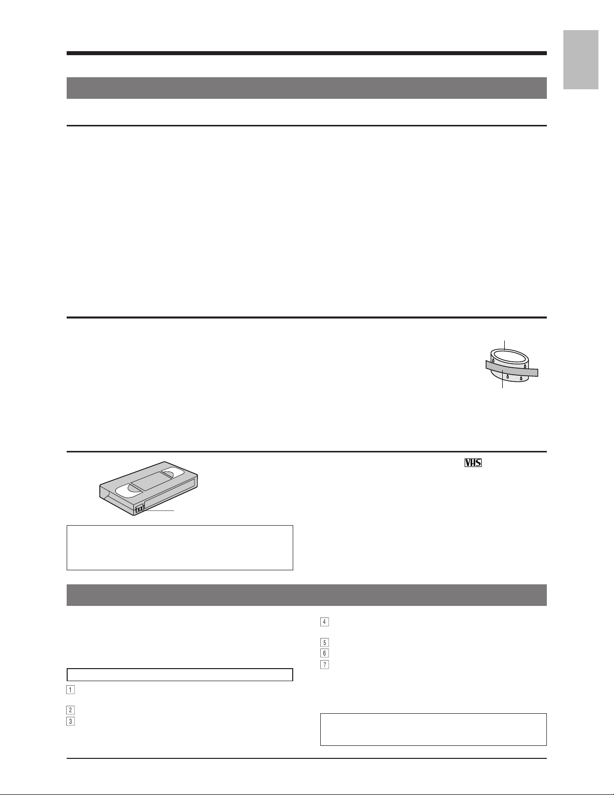
Video cassette
Erasure prevention tab
Timelapse recording is performed over very long periods of time
which means that a durable tape is required.
• Use an E-180 tape or shorter.
• Do not use extended tapes (180 minutes or more such as E-240).
1-4 Daily Inspection
Although this unit has been designed for reliable operation
over a long period of time, a daily inspection is recommended
to ensure optimum performance. In particular, be sure to
check the repeat recording function on a daily basis.
Inspection procedure
1
Turn on the power for all units connected to the
surveillance system.
2
Check the quality of the image shown on the monitor.
3
Check that the date and time shown on the monitor are
correct.
• Only use video cassette bearing the
• To prevent accidental erasure of a recorded tape, break
the erasure prevention tab on the cassette. To use a
cassette with a broken tab, place a piece of cellophane
tape over the broken tab.
• Video cassettes cannot be used upside down.
• Leaving the tape in a partially wound condition for a long
time may damage the tape. Rewind the tape to the
beginning before storage.
4
Rewind the tape recorded the previous day for several
seconds.
5
Press the play button for playback.
6
Check that the playback picture is normal.
7
Check that the recorded date and time are correct.
• This unit includes a Recording Check function (using
the [REC CHECK] button) and an Automatic
Recording Check function for daily checking of
recording quality.
If any problems are found after inspection, turn the power off,
unplug the power plug from the AC outlet, and contact your
JVC dealer.
mark.
PAL
7
Page 7
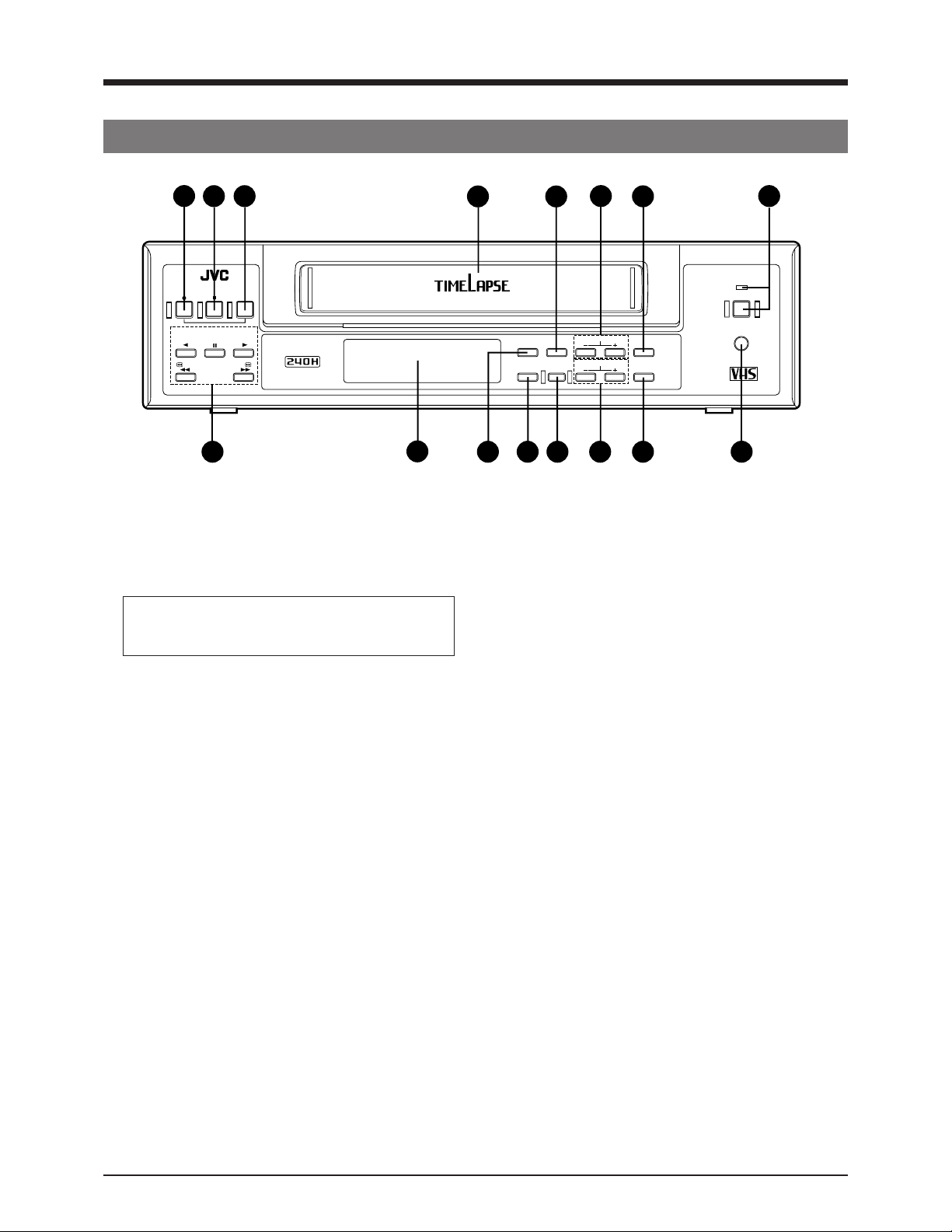
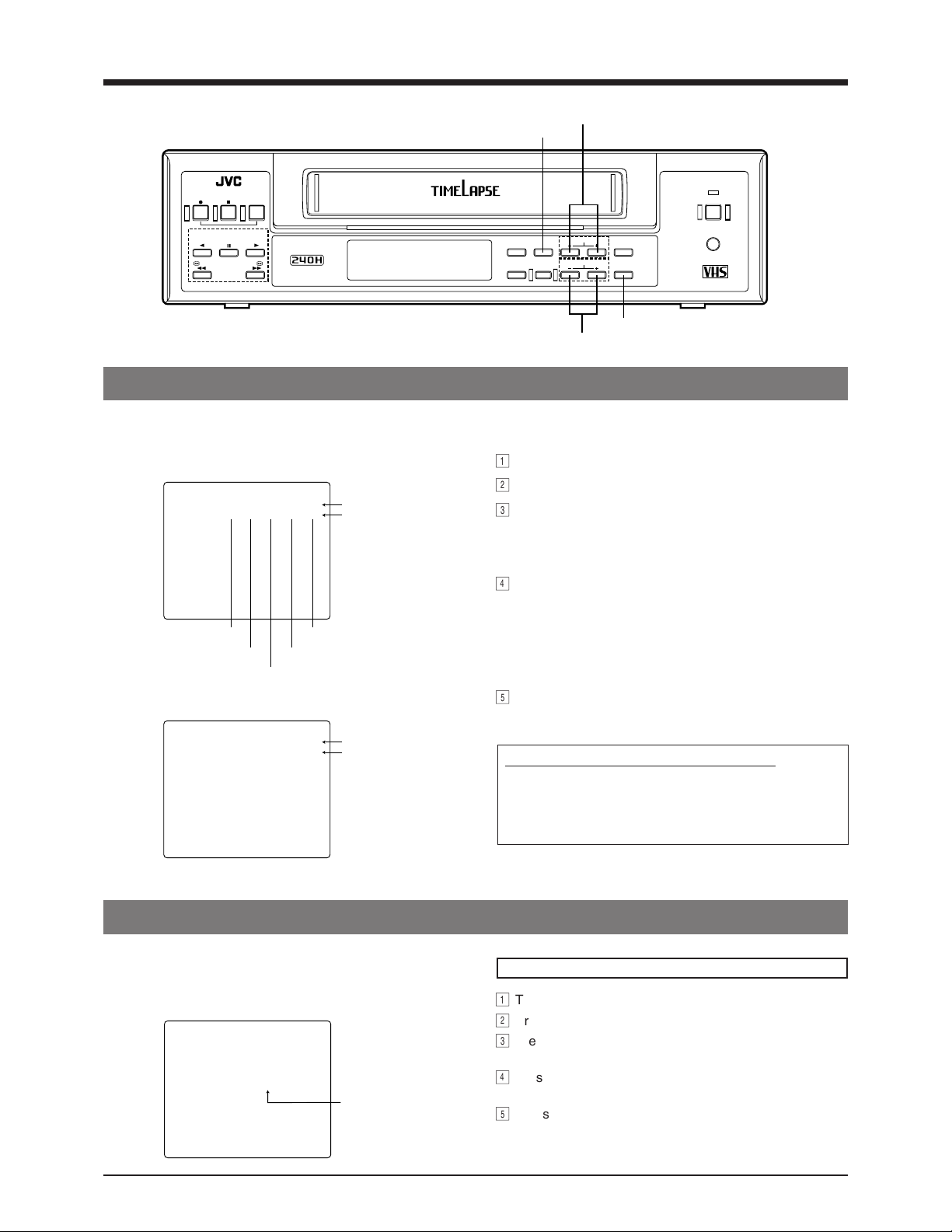
2 CONTROLS AND CONNECTORS
2-1 Front Panel
5
4
3
REC
STOP/EJECT
REC
REVERSE
PAUSE/
STILL
CHECK
PLAY
FFREW
6
1 [OPERATE] button
Press to turn the operating power ON/OFF. When this
button is ON, the OPERATE indicator lights and the unit
can be operated. When a cassette is inserted, the
power switches on and the OPERATE indicator lights
automatically.
The OPERATE button does not completely shut off
the mains power to the unit, but switches the
operating current on and off.
2 Cassette loading slot
For cassette loading and unloading. Use a VHS
cassette tape.
3 [REC CHECK] button
Use to check recording.
When pressed in the Record mode, this will rewind the
tape about 4 seconds and then play back the rewound
section so that the recording quality can be checked.
After playback, the Record mode is automatically reengaged at the point where recording was interrupted.
• The FM level is checked during playback in Recording
Check operation to determine whether or not picture
quality is defective. If it is judged defective, the heads
are automatically cleaned. How this operation is
performed is determined by the setting of the [REC
CHECK] switch in the function menu.
– When set to "MANUAL":
Head cleaning is performed once and recording
resumes.
– When set "AUTO":
Head cleaning is performed once and recording is
resumed for several seconds. Then, Recording
Check operation is performed again.
If picture quality is again judged defective, head
cleaning is performed once again and "E-09" is shown
on the display to indicate that there is a problem.
Recording will continue, however.
2
VIDEO CASSETTE RECORDER
7
12
13
14
RESET
/CANCEL
AL/PL
RESET
15
SR-9240E
11
COUNT/
CLOCK
TIME
MODE
8
9 10
MENU
TIMER
REC
SHIFT/TRACKING
SET/V.LOCK
1
OPERATE
OPE. LOCK
PAL
16
4 [STOP/EJECT] button
• Stops the tape.
• Ejects the tape when pressed in the Stop mode.
5 [REC] button
Starts recording when pressed in the Stop mode.
6 Operation buttons
[PLAY] button
Starts playback.
[PAUSE/STILL] button
• Temporarily stops recording when pressed in the
Record mode.
• Displays a still picture when pressed in the Play mode.
• Advances field by field when pressed in the Still mode.
[REVERSE] button
Starts reverse playback when pressed in the Play or Still
mode.
[FF] button
• Fast forwards the tape.
• Starts fast-forward shuttle search when pressed in the
Play mode.
• If the function menu switch <INDEX SEARCH> is set
to ON and an alarm-recorded tape is loaded, Index
(alarm) Search starts in the forward direction when this
button is pressed in the Stop or Play mode.
[REW] button
• Rewinds the tape.
• Starts reverse shuttle search when pressed in the Play
mode.
• If the function menu switch <INDEX SEARCH> is set
to ON and an alarm-recorded tape is loaded, Index
(alarm) Search starts in the reverse direction when this
button is pressed in the Stop or Play mode.
8
Page 8

2 CONTROLS AND CONNECTORS
2-1 Front Panel
7 Display section
For details, refer to page 10.
8 [COUNT/CLOCK] button
Press this button to select the time display or tape
counter in the display.
When the power is turned off, the time is displayed.
9 [TIME MODE] button
Use to select the recording or playback time mode.
Each time this button is pressed, the recording/playback
time mode changes in the following sequence.
3H (VHS SP mode)
72H[ 96H[ 120H[ 168H[ 240H[ 3H (VHS
SP mode) ....
The selected recording/playback time mode is shown on
the display.
[ L12H[ L24H[ 48H[
0 [TIMER REC] button
Press this button to execute the timer recording. For
details, refer to "Timer Recording" on page 28.
! [MENU] button
Press this button to display the date/time setting, timer
program setting, various function menu setting and hour
meter. Press again to cancel the display.
@ [SHIFT/TRACKING +, -] buttons
• Press to select an item in date/time setting, timer
program setting and function menu setting.
• Press to adjust tracking and reduce noise if there are
tracking problems in the 3H (VHS SP) mode or during
search.
* Tracking adjustment is not possible in the Timelapse
Play mode.
# [SET/V. LOCK +, -] buttons
• Press to set values in date/time setting, timer program
setting and function menu setting.
• Press to reduce the vertical shifting of the picture in
the Still mode.
$ [RESET/CANCEL] button
• Normally press this button to reset the tape counter to
0000.
• When the buzzer sounds, press this button to stop the
buzzer sound.
• In the Timer Program Setting mode, press this button
to cancel the program settings. For details, refer to
"Timer Recording" on page 31.
% [AL/PL RESET] alarm/power loss reset button
Press this button to stop alarm recording or reset the
alarm input or power loss data. For details, refer to
page 34.
^ [OPE. LOCK] button
Press to activate the operation lock function.
9
Page 9
2 CONTROLS AND CONNECTORS
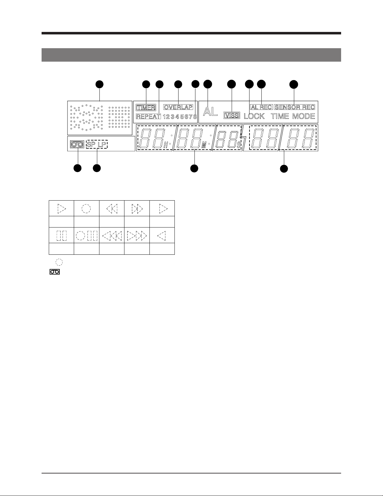
2-2 Display
1 6 8
7 10
2 3
1 Operation mode display
Shows the operation modes.
Playback Recording
Still
* (
) mark in the Rec/Pause mode is shown in red.
Recordpause
Rewind
Rewind
search
Fastforward
Fast-forward
search
2 Cassette indication
Lights when a cassette is loaded. Blinks when a
cassette is being ejected.
3 SP/LP indication
Shows the VHS standard (SP) mode during recording/
playback.
During Timelapse Recording/Playback mode, the SP
indicator is shown.
When a tape recorded in the LP mode is played back,
the "LP" indication is shown.
4 Tape counter/time indication
• When the power is turned on, the tape counter or
current time are shown. The display can be selected
with the [COUNT/CLOCK] button.
• When the power is turned off, the present time (hour,
minute, second) is shown.
5 Recording/playback mode time display
• Shows the recording/playback mode set with the [TIME
MODE] button.
• When a tape ends in the Record mode, the record time
mode indication goes out and the "End" indication
blinks (when the <REC REMAIN> menu switch is set
to "OFF"). If the <REC REMAIN> menu switch is set
to "180S" or "360S", the "End" indication blinks
3 minutes or 6 minutes before the tape ends.
• When an problem occurs, the error indication “E-∗∗”
blinks. For details, refer to page 43.
Timelapse
playback
Reverse
playback
9
11 12
4
13
14
5
6 TIMER indication
Lights during timer recording programming/operation.
7 REPEAT indication
Lights when the VCR is in the Repeat Record mode.
8 OVERLAP indication
Blinks when programs scheduled for timer recording
overlap.
9 Timer program number
During timer recording, the number of program being
recorded blinks.
When the timer recording ends, this number goes out.
0 AL (alarm) indication
Shown during alarm recording. Blinks when alarm
recording ends.
! VISS indication
Shown when the alarm recording start point is indexsearched. For details, refer to “Index Search” on page
42.
@ LOCK indication
Lights when the operation lock function is activated.
# AL REC (alarm recording) indication
Lights when the function menu switch <ALARM REC> is
set to “ON”.
$ SENSOR REC (sensor recording) indication
Lights when the function menu switch <SENSOR REC>
is set to “ON”.
10
Page 10
2 CONTROLS AND CONNECTORS
2-1 FRONT PANEL
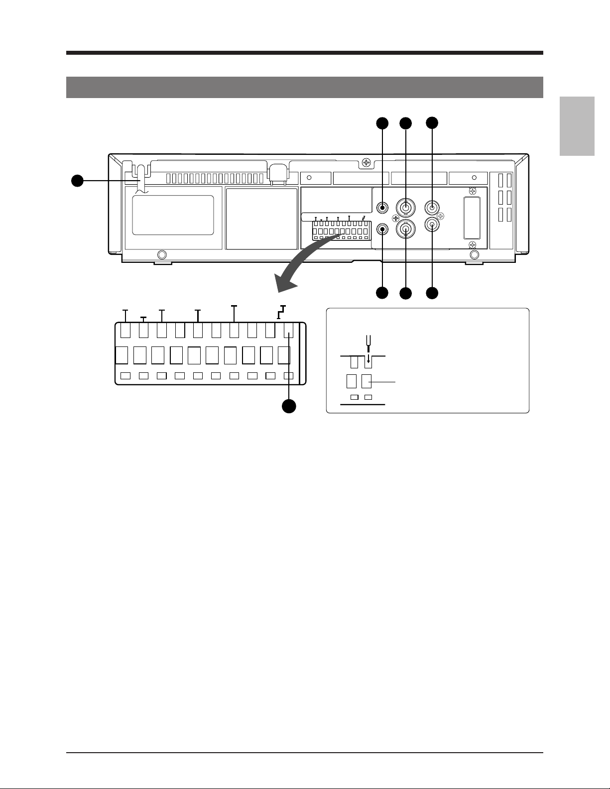
2-3 Rear Panel
2 3
4
1
MIC
VIDEO
CAM SW
OUT
COM
ALARM
IN
ALARM
RESET
ALARM
REC OUT
END OUT
TAPE
COM
WARNING
SERIES/CLOCK
/REC
OUT
IN OUT
IN
CAM SW
ALARM
ALARM
SERIES/CLOCK
OUT
COM
IN
REC OUT
WARNING
ALARM
TAPE
COM
/REC
END OUT
OUT
IN OUT
REMOTE
RESET
7
Connecting the wires to the terminals
6
AUDIO
IN IN
OUT
5
OUT
8
1. Hold the button down
and insert the wire
over the top of the
terminal.
button
2. Release the button to
lock the wire in the
terminal.
8
1 Power cable
Connect the power plug to an AC 220-240 V, 50/60 Hz
outlet.
2 [MIC IN] mic input connector
Connect a microphone with 3.6-mm dia. plug. When
signals are input from both the microphone connector
and the audio input connector, audio signals are mixed
and recorded.
3 [VIDEO IN] video input connector (BNC)
Receives composite video signals from a connected
camera or other video source.
4 [AUDIO IN] audio input connector (RCA)
Receives audio signals from a connected audio source.
5 [AUDIO OUT] audio output connector (RCA)
Outputs audio signals.
6 [VIDEO OUT] video output connector (BNC)
Outputs composite video signals. Input camera signals
(composite video signals) can still be output through this
connector even when no power is supplied to the unit
(Power-Off Video Throughput function).
7 [REMOTE] remote connector
Connect the optional RM-G30U remote control.
8 [SERIES/CLOCK OUT] series recording signal/clock
reset signal output terminal
Outputs the series recording signals or clock reset
signals.
Select the output signal with the <TERMINAL SEL 1>
menu switch.
• Series recording signal output
When the <TERMINAL SEL 1> menu switch is set to
“SERIES”, the series recording signal is output.
• Connect to the other VCR series recording signal input
terminal. When the tape being recorded in this unit
ends, a signal is output from this terminal to the
connected VCR.
• Set the signal output timing with the menu switch
<REC REMAIN> in the 3H to L24H Record modes or
with the menu switch <COUNT END> in the 48H to
240H modes.
For details on settings, refer to the menu switch
descriptions on page 21.
• Clock reset signal output
When the <TERMINAL SEL 1> menu switch is set to
“C.ADJ”, the clock reset signal is output when the
internal clock is at AM0:00 and PM0:00. When
connected to the [CLOCK IN] terminal of another
SR-9240E/EK, this unit’s time can be synchronised
with the time on the other VCR if the time difference is
within ±30 seconds.
11
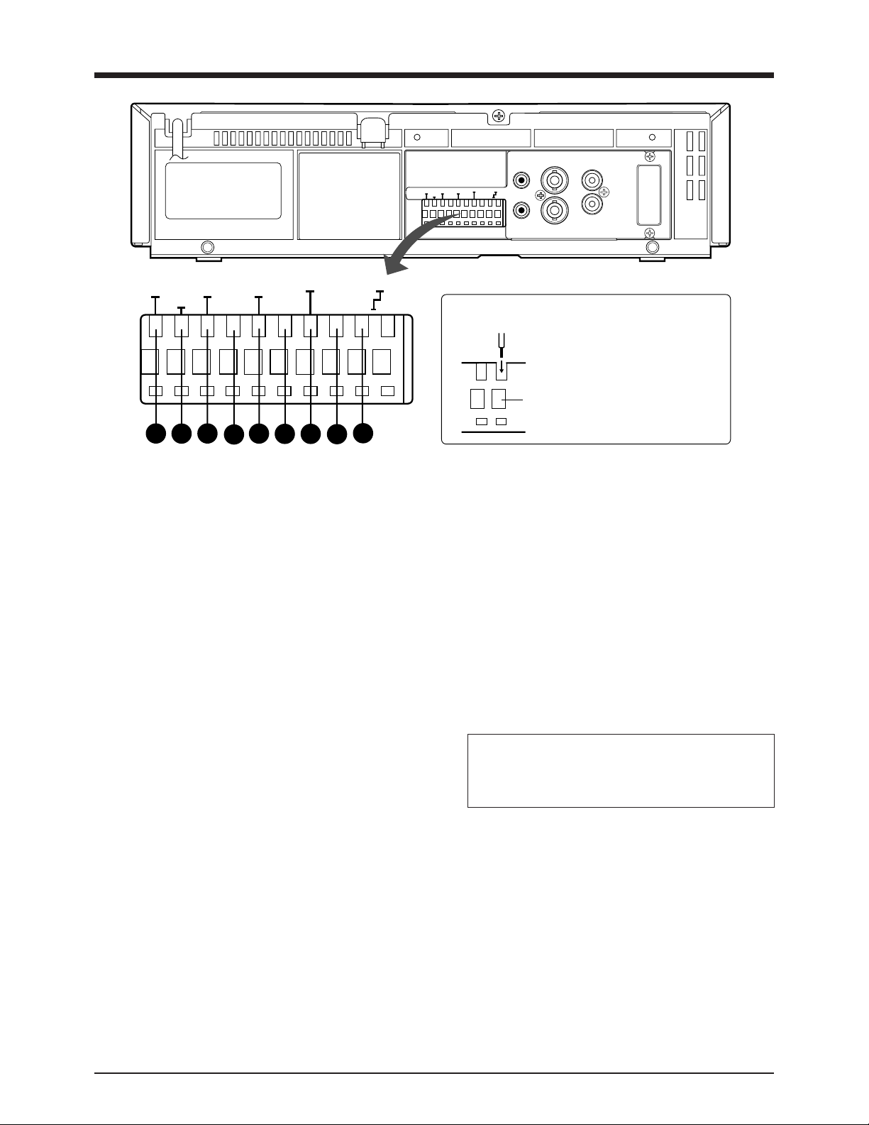
Page 11
2 CONTROLS AND CONNECTORS
CAM SW
MIC
VIDEO
IN
ALARM
ALARM
SERIES/CLOCK
OUT
COM
IN
REC OUT
WARNING
ALARM
TAPE
COM
/REC
END OUT
OUT
IN OUT
REMOTE
RESET
AUDIO
IN IN
OUT
OUT
CAM SW
OUT
17
COM
16
ALARM
IN
15
ALARM
RESET
14
ALARM
REC OUT
END OUT
13
TAPE
12
COM
WARNING
11
SERIES/CLOCK
/REC
OUT
IN OUT
9
10
9 [SERIES/CLOCK IN] series recording signal/clock
reset signal input terminal
Input the series recording signals, VCR activation
signals from the external control equipment or clock
reset signals.
Select the input signal with the <TERMINAL SEL 1>
menu switch.
• Series recording signal input
When the <TERMINAL SEL 1> menu switch is set to
“SERIES”, the series recording signal is input.
• Connect to the other VCR series recording signal
output terminal.
• When a series recording signal is received from the
other VCR, recording starts automatically.
• VCR activation signal input
• When the <TERMINAL SEL 1> menu switch is set to
“EXT”, recording start and stop can be controlled with
external signal input.
• Connect to an external control device.
When a VCR activation signal (ground input) is
received, recording starts automatically and continues
for as long as the VCR activation signals are input.
• Clock reset signal input
When the <TERMINAL SEL 1> menu switch is set to
“C.ADJ”, the clock reset signal from the master clock
can be received.
• Inputting the clock reset signal synchronises the time
with the master clock time if the time difference is
within ±30 seconds. If the difference exceeds
30 seconds, the time will not be adjusted correctly.
0 [WARNING/REC OUT] warning signal/rec signal
output terminal
Outputs a warning signal or recording mode signal. The
type of output signal can be selected with the
<TERMINAL SEL 2> menu switch.
• Warning signal output
When the <TERMINAL SEL 2> menu switch is set to
“WARNING”, a warning signal (+12 V) is output if an
abnormality occurs in tape transport or mechanism
operation.
Connecting the wires to the terminals
9 to &
1. Hold the button down
and insert the wire
over the top of the
terminal.
button
2. Release the button to
lock the wire in the
terminal.
• Recording mode signal output
When the <TERMINAL SEL 2> menu switch is set to
REC and the unit is in the Record mode, the recording
mode signal (+12 V) is output.
! [COM] common ground terminal
Connect to the ground terminal of a connected unit.
@ [TAPE END OUT] tape end signal output terminal
Outputs a Tape End signal when the tape ends during
recording.
• Outputs a +12 V signal during recording, playback, FF
and rewind. When the tape ends during recording, a 0
V (GND level) signal is output.
• When the tape ends during auto repeat recording,
signals are output for about 2 seconds.
• Connect an external alarm lamp or buzzer via an
external interface.
• To cancel the output, press the EJECT button, STOP
button or REW button.
Set the signal output timing with the menu switch <REC
REMAIN> in the 3H to L24H Record modes or with the
menu switch <COUNT END> in the 48H to 240H modes.
For details on settings, refer to the menu switch descriptions
on page 21.
# [ALARM REC OUT] alarm recording mode signal
output terminal
Outputs +12 V signals during alarm recording.
$ [ALARM RESET] alarm signal reset input terminal
Receives signals to cancel alarm recording.
• Alarm input data is not reset.
% [ALARM IN] alarm signal input terminal
Receives signals to start alarm or sensor recording.
^ [COM] common ground terminal
Connect to the ground terminal of a connected unit.
& [CAM SW OUT] camera switching signal output
terminal
When a sequential switcher is connected, this terminal
outputs camera switching timing control signals. For
details, refer to page 54.
12
Page 12
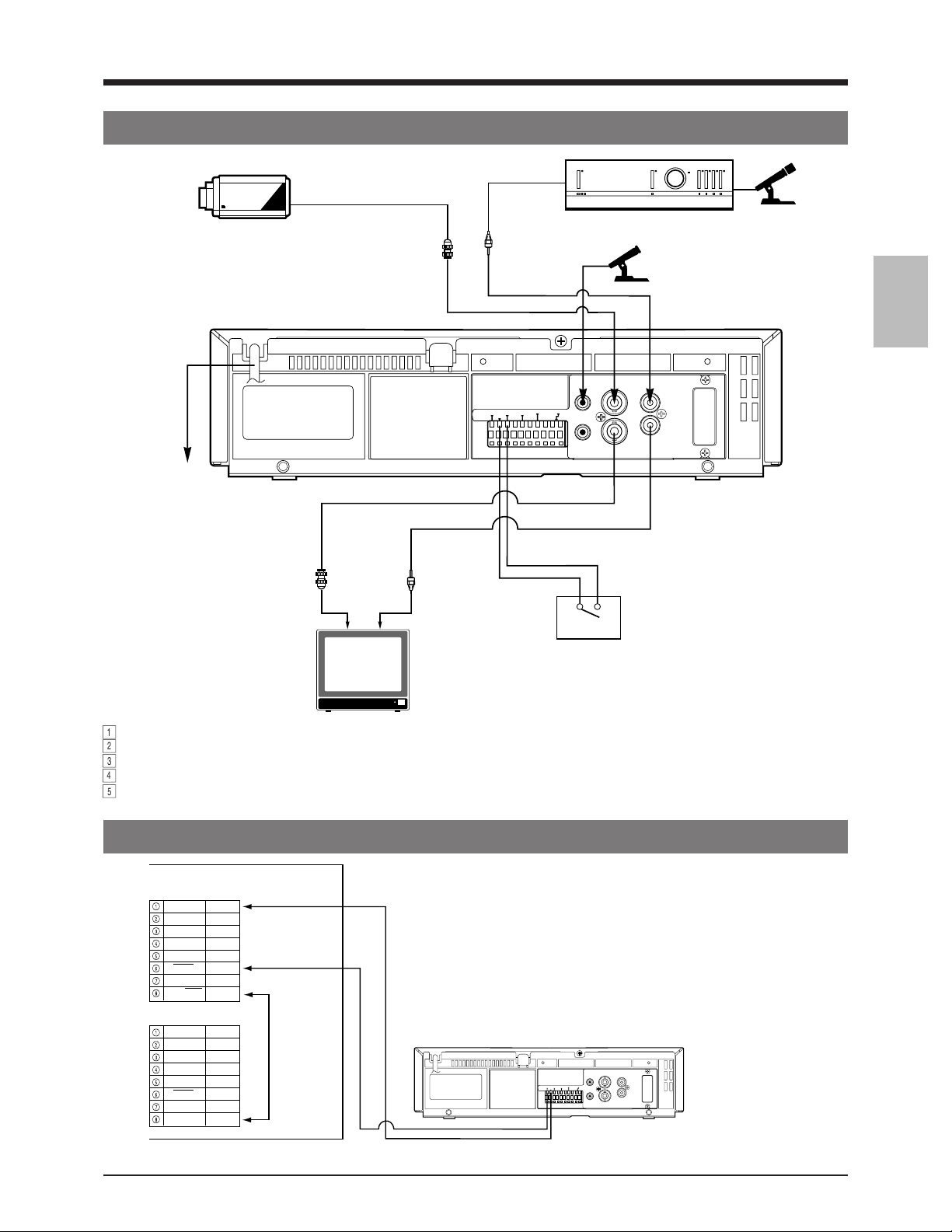
3 CONNECTIONS
3-1 Connecting to a Camera
AC 220-240 V
CCD
Video camera
Monitor TV
BNC
BNC
RCA
CAM SW
OUT
RCA
ALARM
IN
ALARM
COM
RESET
ALARM
REC OUT
END OUT
COM
WARNING
TAPE
/REC
OUT
MIC
VIDEO
IN
SERIES/CLOCK
IN OUT
REMOTE
Alarm sensor
Amplifier
Microphone
AUDIO
IN IN
OUT
OUT
Microphone
1
Connect the monitor’s video/audio input connectors to the SR-9240E/EK’s video/audio output connectors.
2
Connect the video camera’s video output connector to the SR-9240E/EK’s video input connector.
3
Input audio signals to the audio input connectors via an amplifier.
4
When connecting an alarm sensor, connect it to the SR-9240E/EK’s alarm input terminal.
5
When the connection is complete, connect the power plug to an AC 220-240 V, 50/60 Hz outlet.
CONNECTION TO THE SW-501E/SW-502E SEQUENTIAL SWITCHER
SW-501E/SW-502E
JK102/JK202
D.GND
AT 1
AT 0
CS1 0
CS0 1
TMP1
SODT
IN/OUT
SLV/MST
JK103/JK203
D.GND
AT 0
AT 1
CS0 1
CS1 0
TMP0
SODT
IN/OUT
D. +5 V
Sequential switcher
SW-501E/SW-502E
IN
OUT
IN
OUT
IN
IN
OUT
IN
OUT
IN
OUT
OUT
–
TIMER INPUT
connector
–
TIMER OUT
connector
1. Connect pin 6 on the sequential switcher's TIMER INPUT
connector to the VCR's CAMERA SW OUT terminal. Connect
pin 1 to the GND terminal.
2. Connect pin 8 on the sequential switcher's TIMER INPUT
connector to pin 8 on its TIMER OUT connector.
Note:
● Be sure to use two DIN connectors for connections.
MIC
VIDEO
AUDIO
IN
CAM SW
ALARM
ALARM
OUT
IN
REC OUT
ALARM
TAPE
COM
RESET
END OUT
IN IN
SERIES/CLOCK
COM
WARNING
/REC
OUT
IN OUT
REMOTE
OUT
OUT
13
Page 13
3 CONNECTIONS
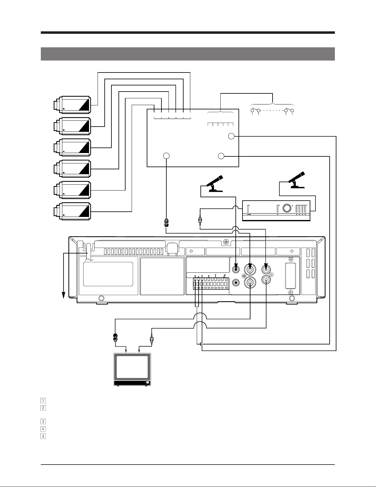
3-2 Connecting a System Using a Sequential Switcher
Video cameras
CCD
CCD
CCD
CCD
CCD
1 2 3 4 5 6
Alarm signal output
Video output
Alarm sensor input
1 2 3 4 5 6
Camera
switching
signal input
Microphone
Alarm sensor
Sequential switcher
Microphone
CCD
AC 220-240 V
BNC
Monitor TV
BNC
RCA
CAM SW
RCA
MIC
VIDEO
IN
ALARM
ALARM
SERIES/CLOCK
OUT
COM
IN
REC OUT
WARNING
ALARM
TAPE
COM
/REC
END OUT
OUT
IN OUT
REMOTE
RESET
AUDIO
IN IN
OUT
OUT
1
Connect video cameras and alarm sensor to a sequential switcher (frame switcher).
2
Connect the sequential switcher’s (frame switcher) alarm signal output, camera switching signal input and video output to
the SR-9240E/EK.
3
Connect the monitor’s video/audio input connectors to the SR-9240E/EK’s video/audio output connectors.
4
When the connection is complete, connect the power plug to an AC 220-240 V, 50/60 Hz outlet.
5
Synchro should be applied to all connected video cameras.
14
Page 14
3 CONNECTIONS
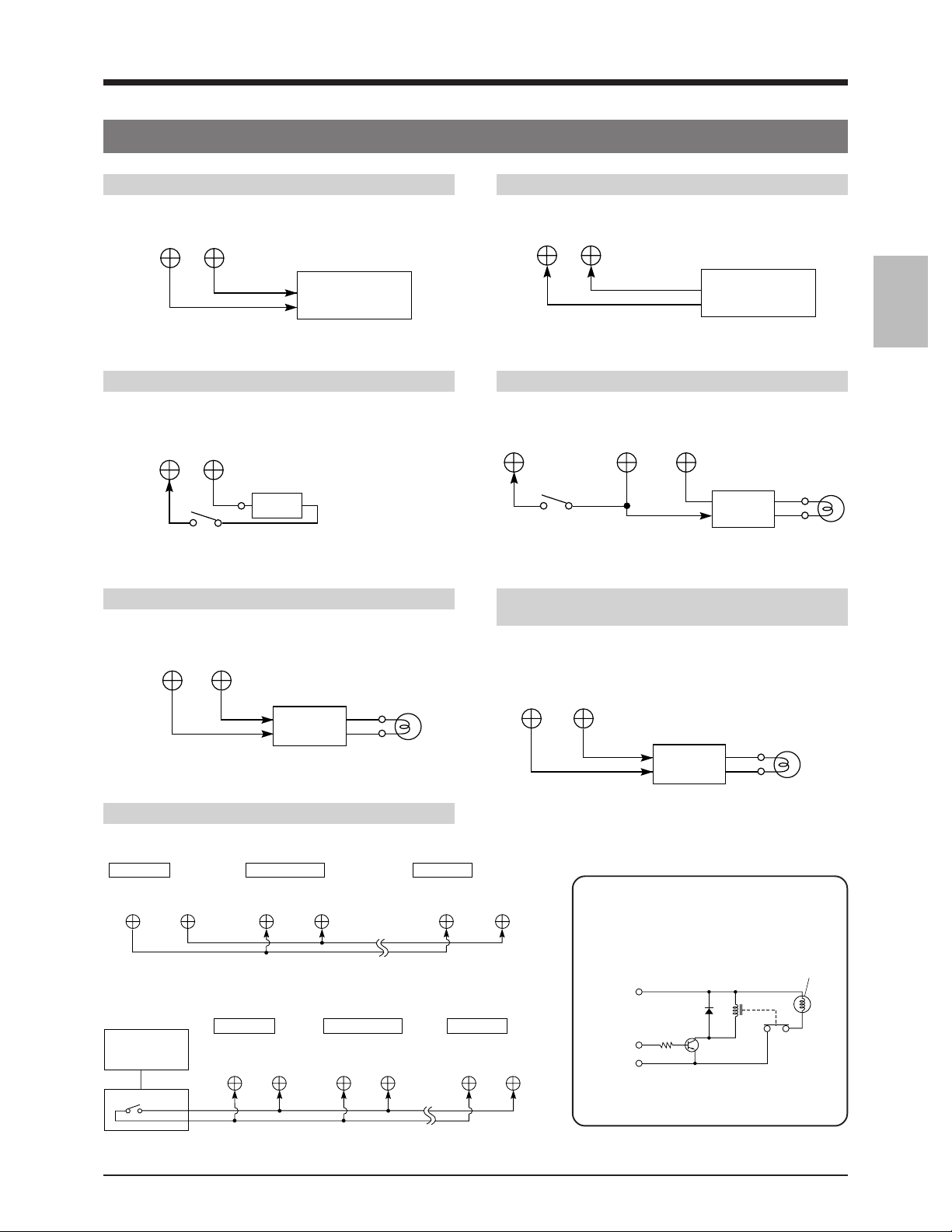
3-3 Connecting the Rear Panel Input/Output Terminal Connections
[CAM SW OUT] camera switching signal output terminal
CAM SW
COM
OUT
Sequential switcher
camera switching
signal input
[ALARM RESET] alarm reset terminal
ALARM
RESET
COM
Vcc
Switch
Vcc: 5V–12V
[ALARM IN] alarm signal input terminal
ALARM
COMIN
Sequential switcher
alarm output
terminal
[ALARM REC OUT] alarm recording mode signal output terminal
ALARM
RESET
Switch
ALARM
REC OUT COM
External
interface
[TAPE END OUT] tape end output terminal [WARNING/REC OUT] warning signal/recording
mode signal output terminal
TAPE
END OUT
COM
WARNING
/REC
COM
Alarm lamp
External
interface
External
interface
Alarm lamp
OUT
Alarm
lamp
[CLOCK IN/OUT] clock reset terminal
5 When setting the clock to the first VCR’s clock
First VCR Second VCR Last VCR
CLOCK
OUT
CLOCK
INCOM
COM
CLOCK
5 When setting the clock to the external master clock
First VCR Second VCR Last VCR
External
master clock
CLOCK
IN
COM
CLOCK
COM
IN COM
IN
CLOCK
COM
External interface example
Example: Lamp lights with HIGH signal
Power
supply
Control
IN
signal
GND
(Lamp, etc.)
Relay
5 Use appropriately rated devices.
15
Page 15
4 MONITOR ON-SCREEN DISPLAY
Status information and other data including date/time, alarm input data, power loss (power failure) data and total operation
hours can be displayed on a connected monitor. Function settings can be switched via the on-screen function menu switches
and menu screens are also provided for timer recording program setting and date/time setting.
• Normally, the time/date data is shown on screen.
• Additional data displays and menu screens can be displayed by pressing the [MENU] button. This calls up the main menu
screen where you can select items as desired.
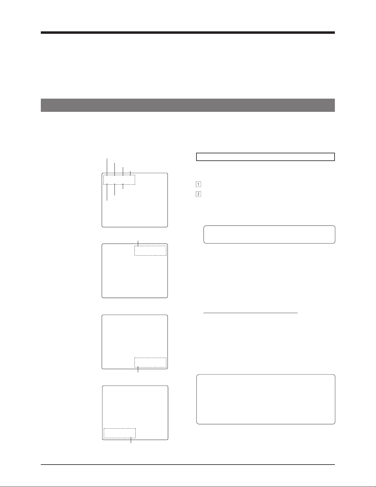
4-1 On-Screen Display in the Time/Date and Record Modes
Time/date and recording mode data is recorded and displayed on screen.
In the Stop, Record and Record Pause modes, data is superimposed on the input video signals.
• The on-screen display can switched ON/OFF using the <POSITION> switch in the function menu's ON SCREEN MODE
setting screen. You can also change the on-screen display position using this switch.
Menu switch
<POSITION> setting
• "L-UP"
• "R-UP"
• "R-BOTTOM"
• "L-BOTTOM"
Hour
Minute
Second
1 2 : 3 0 : 4 5 3 H
1 1 – 6 – 1 9 9 9
Year (last two digits)
Month
Day
Recording mode
Recording mode
3 H 1 2 : 3 0 : 4 5
1 1 – 6 – 1 9 9 9
1 1 – 6 – 1 9 9 9
3 H 1 2 : 3 0 : 4 5
Recording mode
Display
5 Connect the VCR's video output connector to the
monitor's video input connector.
1
Turn the power on (monitor and VCR).
2
• When a video signal is input to the video input
connector, time/date, and recording mode are
superimposed on the picture.
• If there is no signal input, display data is
superimposed on a black background.
* If the date and time have not been set, correct date
and time indications are not available.
5 If no on-screen data is displayed, set the <POSITION>
menu switch in the function menu's ON SCREEN MODE
setting screen to the desired position (except "OFF").
5 Changing the display position
You can select the position on screen where data is
displayed with the <POSITION> menu switch in the ON
SCREEN MODE setting screen. Data can be displayed
in any one of the four corners of the screen.
Setting of the menu switch <POSITION>
– L-UP : Left top (factory setting)
– R-UP : Right top
– R-BOTTOM : Right bottom
– L-BOTTOM : Left bottom
– OFF : Display is off. No indications are
shown.
● For "Function menu switch setting", refer to page 19.
• In the Record mode, on-screen time/date and
recording mode data is recorded together with video
signals.
If you do not want to record on-screen data, set the
<POSITION> menu switch to "OFF".
• In the Play mode, on-screen data recorded on the tape
is displayed.
16
1 1 – 6 – 19 9 9
1 2 : 3 0 : 4 5 3 H
Recording mode
Page 16
4 MONITOR ON-SCREEN DISPLAY
4-2 Main Menu Display
You can display date and time data recorded when an alarm input or power failure occurs, as well as the hour meter (drum
rotating time) by selecting the desired item in the main menu.
The timer recording program setting screen, function menu switch setting screen, and date/time setting screen can also be
displayed by selecting the desired item in the main menu.
VIDEO CASSETTE RECORDER
[MENU] button
COUNT/
MENU
CLOCK
TIME
TIMER
MODE
REC
[SET +/–] buttons
Main menu screen
PROGRAM TIMER
FUNCTION
ALARM IN
POWER LOSS
HOUR METER
CLOCK ADJUST
PRESS (SHIFT, SET)
PRESS (MENU) TO END
[SHIFT +/–] buttons
SHIFT/TRACKING
MAIN MENU
SET/V.LOCK
RESET
/CANCEL
AL/PL
RESET
SR-9240E
OPERATE
OPE. LOCK
Operation
5 Connect the VCR's video output connector to the
monitor's video input connector.
1
Turn on the VCR and the monitor.
2
Press the [MENU] button.
PAL
[ The main menu screen is displayed.
3
Press the [SHIFT +/-] button to move the cursor arrow to
the item you want to display.
• Press the [SHIFT +] button to move the cursor arrow
down. Press the [SHIFT -] button to move it up.
4
Press the [SET +] or [SET -] button to display the
selected item.
5
To end menu operation and restore the normal screen,
press the [MENU] button.
● PROGRAM TIMER:
Displays the program setting screen for timer recording.
* Timer programming is not possible if the date and
time are not set. In this case, the date/time setting
screen will be displayed.
● FUNCTION:
Displays the function menu setting screen.
● ALARM IN:
Displays the date and time when an alarm signal was
input.
● POWER LOSS
Displays the date and time when a power failure
occurred.
● HOUR METER:
Displays the hour meter (drum rotating time).
● CLOCK ADJUST:
Displays the date/time setting screen.
* Set the date and time before using this unit.
• When the [MENU] button is pressed during playback,
the monitor screen display switches from the playback
picture to the input video signal (EE picture) and the
main menu is shown on the screen.
This means that even during playback you can check
menu contents. Press the [MENU] button again to
restore the playback picture.
17
Page 17
4 MONITOR ON-SCREEN DISPLAY
[MENU] button
[SHIFT +/–] buttons
REC
REVERSE
STOP/EJECT
PAUSE/
STILL
REC
CHECK
PLAY
FFREW
VIDEO CASSETTE RECORDER
COUNT/
CLOCK
TIME
MODE
MENU
TIMER
REC
SHIFT/TRACKING
SET/V.LOCK
RESET
/CANCEL
AL/PL
RESET
[AL/PL RESET]
[SET +/–] buttons
button
4-3 Alarm Input/Power Loss Data Display
The dates and times of up to nine (9) alarm inputs or power losses (failures) can be displayed.
1
Alarm input data screen
A L – 0 0 1 2 0 : 3 0 9 – 6 – 9 9
A L – 0 0 2 2 1 : 4 4 1 0 – 6 – 9 9
A L – – – – – – : – – – – – – – – – –
A L – – – – – – : – – – – – – – – – –
A L – – – – – – : – – – – – – – – – –
A L – – – – – – : – – – – – – – – – –
A L – – – – – – : – – – – – – – – – –
A L – – – – – – : – – – – – – – – – –
A L – – – – – – : – – – – – – – – – –
PRESS (AL / PL) TO ALL RESET
PRESS (MENU) TO END
ALARM IN
Hour
Minute
Year
Month
Day
Power loss (failure) data screen
POWER LOSS
P L – 0 0 1 2 1 : 3 0 9 – 6 – 9 9
P L – 0 0 2 1 7 : 4 4 1 0 – 7 – 9 9
P L – – – – – – : – – – – – – – – – –
P L – – – – – – : – – – – – – – – – –
P L – – – – – – : – – – – – – – – – –
P L – – – – – – : – – – – – – – – – –
P L – – – – – – : – – – – – – – – – –
P L – – – – – – : – – – – – – – – – –
P L – – – – – – : – – – – – – – – – –
PRESS (AL / PL) TO ALL RESET
PRESS (MENU) TO END
First alarm
Second alarm
First power failure
Second power
failure
Turn on the VCR and monitor.
2
Press the [MENU] button to display the main menu.
3
Press the [SHIFT +] or [SHIFT -] button to select
ALARM IN or POWER LOSS.
• To display alarm input data, select ALARM IN. To
display power failure data, select POWER LOSS.
4
Press the [SET +] or [SET -] button to display the
selected data (alarm input or power loss).
• When 10 or more alarm input or power loss data
items have been stored, subsequent data will
replace earlier items, beginning from the second
item.
5
Press the [MENU] button to end menu operation and
restore the normal screen.
Resetting alarm input/power loss (failure) data
When the "AL" (alarm) display is off and the VCR is in
the normal screen mode, press the [AL/PL RESET]
button to reset the alarm input and power loss data
stored in memory.
SR-9240E
OPERATE
OPE. LOCK
PAL
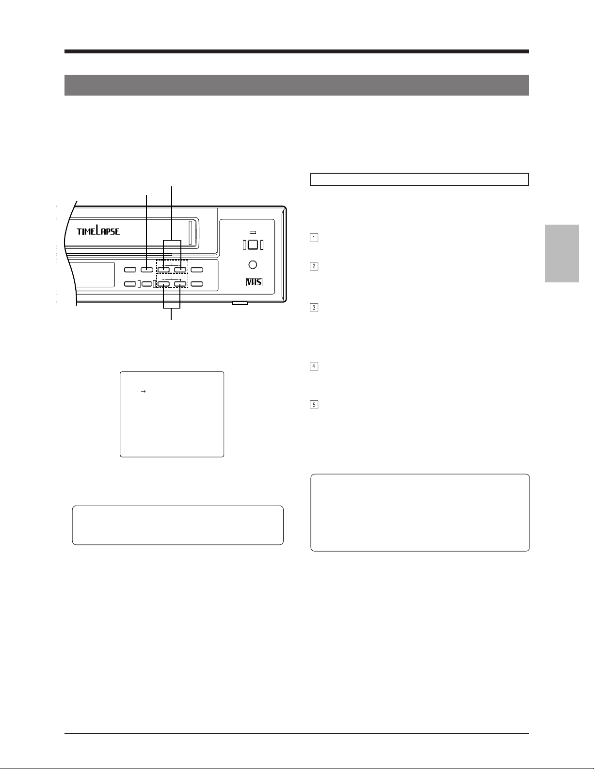
4-4 Hour Meter Display
Drum rotating time is displayed in the form of an hour
meter. Use this data to schedule maintenance.
Hour meter screen
HOUR METER
DRUM ON 02345H
18
PRESS (MENU) TO END
Drum rotating time
Operation
1
Turn on the VCR and monitor.
2
Press the [MENU] button to display the main menu.
3
Press the [SHIFT +] or [SHIFT -] button to select HOUR
METER.
4
Press the [SET +] or [SET -] button to display the hour
meter (drum rotating time).
5
Press the [MENU] button to end menu operation and
restore the normal screen.
Page 18

5 SETTING OF THE FUNCTION MENU SWITCHES
You can customize the VCR's functions to suit the requirements of your application using on-screen menu's function switches.
[MENU] button
COUNT/
CLOCK
PAL
TIME
MODE
MENU
TIMER
REC
SHIFT/TRACKING
[SET –] button
[SHIFT +] button
SET/V.LOCK
[SET +] button
RESET
/CANCEL
AL/PL
RESET
● Menu function switches are available on four setting screens: ON SCREEN MODE, VTR MODE 1, VTR MODE 2 and
ALARM/SENSOR REC mode. (When the optional SA-K97U RS-232C interface board is installed, the RS-232C
PARAMETER setting screen is also available.)
5-1 Function Menu Switch Setting
[MENU] button
Normal screen
[SHIFT –] button
[MENU]
button
Main menu screen
PRESS (SHIFT, SET)
PRESS (MENU) TO END
[MENU]
button
On-screen mode setting VTR mode 1 setting VTR mode 2 setting
MAIN MENU
PROGRAM TIMER
FUNCTION
ALARM IN
POWER LOSS
HOUR METER
CLOCK ADJUST
• When the optional SA-K97U RS-232C interface
board is installed, the RS-232C PARAMETER
setting screen is also available.
[SET
+/-]
buttons
ON SCREEN MODE
(POSITION) L –UP
●
PRESS (SHIFT, SET)
PRESS (MENU) TO END
VTR MODE 1
(SHARPNESS) NORMAL
(VIDEO MODE) AUTO
(AUTO REC) OFF
(REC CHECK) NORMAL
(TAPE END MODE) REPEAT
(INDEX SEARCH) OFF
(CAMERA SW) OFF
(TAPE END BUZZER) OFF
(WARNING BUZZER) OFF
PRESS (SHIFT, SET)
PRESS (MENU) TO END
• Select an item with the [SHIFT +/-] buttons.
• Enter the selected values with the [SET +/-] buttons.
VTR MODE 2
(SUMMER TIME) OFF
(TAERMINAL SEL 1) SERIES
(TAERMINAL SEL 2) WARN
(REC REMAIN) OFF
(COUNT END) OFF
PRESS (SHIFT, SET)
PRESS (MENU) TO END
Alarm/sensor recording
mode setting
A LARM / SENSOR REC MODE
(ALARM REC) OFF
(SENSOR REC) OFF
(DURATION) 180SEC
(BUZZER) OFF
(TAPE END MODE) STOP
PRESS (SHIFT, SET)
PRESS (MENU) TO END
Preparation
5 Connect the VCR's video output connector to the
monitor's video input connector.
5 Turn on the VCR and the monitor.
1
Press the [MENU] button to display the main menu.
2
Press the [SHIFT +] or [SHIFT –] button to select
FUNCTION.
3
Press the [SET +] or [SET –] button.
[ The ON SCREEN MODE setting screen is
displayed.
• Only one menu switch is available in the ON SCREEN
MODE setting screen. This switch (<POSITION>)
allows you to select the screen position of the onscreen display and to switch it ON/OFF.
4
Press the [SET +] or [SET –] button to enter the selected
position.
5
To display another setting screen, press the [SHIFT +/–]
button.
• Press the [SHIFT +] button to display the VTR mode 1
setting screen.
• Press the [SHIFT –] button to display the alarm/sensor
recording mode setting screen.
6
The VTR mode 1, VTR mode 2 and alarm/sensor
recording mode setting screens include several menu
switches.
Press the [SHIFT +] or [SHIFT –] button to select the
item you want to set.
• When the cursor arrow reaches the last item (bottom of the
screen) pressing the [SHIFT +] button advances the
display to the next menu switch setting screen.
e.g.: (WARNING BUZZER)
[ (SUMMER TIME)
• When the cursor arrow is at the first item (top of the
screen), pressing the [SHIFT -] button will change the
display to the previous menu switch setting screen.
e.g.: (SHARPNESS)
7
Press the [SET +] or [SET –] button to enter the selected
[ (POSITION)
value.
To set more than one menu switch, repeat steps
6 and 7.
8
End menu switch setting.
Press the [MENU] button twice.
[ The normal screen is restored.
• Set values are stored in the VCR's memory. This
data is retained even when the power is turned off.
19
Page 19

5 SETTING OF THE FUNCTION MENU SWITCHES
5-2 Contents of the Function Menu Switches
Three function menu switch setting screens are available.
[ ]: Factory setting
On-screen POSITION [L-UP]
mode setting R-UP
R-BOTTOM
L-BOTTOM
OFF
VTR mode 1 SHARPNESS [NORMAL]
setting SHARP
VIDEO MODE [AUTO]
B/W
AUTO REC [OFF]
ON
REC CHECK [MANUAL]
AUTO
TAPE END [STOP]
MODE REW
REPEAT
EJECT
Sets the on-screen position of time/date and recording mode data. If no onscreen display is required, use this menu switch to turn it off.
L-UP : Display is shown in the top left corner of the screen.
R-UP : Display is shown in the top right corner of the screen.
R-BOTTOM : Display is shown in the bottom right corner of the screen.
L-BOTTOM : Display is shown in the bottom left corner of the screen.
OFF : The on-screen display is not shown.
Selects the picture quality in the Play mode.
NORMAL : Normal picture quality.
SHARP : Picture contours are emphasized.
Allows you to force Black and White recording regardless of the type of signal
input.
AUTO : Normally set to this mode. Recording automatically conforms to the
type of signal input (Colour or Black and White).
B/W : Even if a colour video signal is input, recording is performed in the
Black and White mode. A higher resolution picture can be obtained
than in the Colour mode.
Enables or disables automatic external timer recording or automatic restart of
recording after a power failure.
OFF : External timer recording or automatic recording after power failure is
disabled.
ON : Recording starts automatically when power is turned on.
Sets whether or not Recording Check is automatically performed at the
beginning of a tape in the Repeat Recording mode. Also sets what action is
taken if picture quality is found to be defective when Recording Check is
activated with the [REC CHECK] button.
MANUAL:
• If picture quality is found to be defective when Recording Check is activated
with the [REC CHECK] button, head cleaning is performed once and recording
resumes. The error indication "E-09" is shown on the display for 10 seconds.
• Automatic Recording Check is not performed at the beginning of a tape set to
record repeatedly.
AUTO:
• If picture quality is found to be defective when Recording Check is activated
with the [REC CHECK] button, head cleaning is performed and recording
resumes for several seconds, then the recording is automatically checked
again. If the picture quality is still defective, head cleaning is performed again
and the error indication "E-09" is shown on the display. The error indication
remains displayed while recording continues.
• Automatic Recording Check is performed at the beginning of a tape set to
record repeatedly.
If the picture quality is defective, Recording Check is performed again. If the
picture quality is still defective, head cleaning is performed again and the error
indication "E-09" is shown on the display. The error indication remains
displayed while recording continues.
Sets the operation mode when the tape ends in the Record mode.
( In the Play and FF modes, the tape stops.)
STOP : The tape stops.
REW : The tape automatically rewinds and enters the Stop mode.
REPEAT : In the Record mode, the tape automatically rewinds and then restarts
recording (repeat recording).
EJECT : The tape is ejected.
FunctionScreens Items Set values
20
The operation mode at tape end during recording, in the case
when alarm or sensor recording is executed even once, can be
set with the menu switch <TAPE END MODE> on the alarm/
sensor recording mode setting screen.
Page 20

5 SETTING OF THE FUNCTION MENU SWITCHES
5-2 Contents of the Function Menu Switches
[ ]: Factory setting
VTR mode 1 INDEX [OFF]
setting SEARCH ON
CAMERA SW [OFF]
1 FIELD
1 FRAME
TAPE END [OFF]
BUZZER ON
WARNING [OFF]
BUZZER ON
VTR mode 2 SUMMER TIME [OFF]
setting ON
TERMINAL [SERIES]
SEL 1 EXT
C.ADJ
Enables or disables the Index Search function.
OFF : The index search function is disabled.
ON : When an alarm-recorded tape is put in the FF or REV. Shuttle Search
mode, the VCR searches for the nearest recorded index code (VISS
signal) and engages playback at the indexed position.
When an alarm-recorded tape is fast-forwarded or rewound, the VCR
searches for the nearest index code and enters the Stop mode at the
indexed position.
Sets the camera switching interval for output to an external sequential switcher
during recording.
OFF : No camera switching signal is output.
1 FIELD : Set to this position to switch the camera every 1 field.
1 FRAME: Set to this position to switch cameras every 1 frame.
Turns the Tape End buzzer on or off.
OFF : The buzzer does not sound at tape end.
ON : When the tape reaches the position set with the <REC REMAIN> or
<COUNT END> menu function switch during recording, a buzzer sounds.
To stop the buzzer sound, press the [REW] button, [EJECT] button,
[STOP] button, [RESET/CANCEL] button or [OPERATE] button.
When the mode is changed, the buzzer sound stops.
Turns the warning buzzer on or off.
OFF : The buzzer does not sound.
ON : The buzzer sounds. To stop the buzzer sound, press the [OPERATE]
button or [RESET/CANCEL] button.
Turns summer time compensation on or off.
OFF : Clock is not adjusted for summer (daylight saving) time.
ON : Clock is adjusted for summer (daylight saving) time.
Selects the signal to be input or output to the [SERIES/CLOCK IN·OUT]
terminals on the rear panel.
SERIES : Set to this position to input or output a series recording signal.
EXT : Set to this position to start or stop the recording with the VCR
activation signal input from an external control device.
C.ADJ : Set to this position to input or output a clock reset signal.
FunctionScreens Items Set values
TERMINAL [WARN.]
SEL 2 REC
REC REMAIN [OFF]
180S
360S
Selects the signal output from the rear panel’s [WARNING/REC OUT] terminal.
WARN. : Set to this position to output a warning signal. The warning signal is
REC : Set to this position to output a recording mode signal (+12 V) in the
Sets the timing to process tape end before the actual tape end. This menu
switch setting is effective in the 3H to L24H Record modes. For the 48H to
240H modes, set with <COUNT END>. The following operations are executed
at the timing set with this menu switch.
• The tape end signal is output from the rear panel's [TAPE END] terminal.
• The series recording signal is output from the rear panel's [CLOCK/SERIES
OUT] terminal (with the TERMINAL SEL 1> function menu switch set to
"SERIES").
• The tape end buzzer sounds (with the <TAPE END BUZZER> function menu
switch set to "ON").
• "End" is shown on the counter display.
The set values (180S/360S) are for the 3H mode. The relation between the
recording mode and the recording time is shown below.
These values should be used as a reference only. Actual values may differ depending on
the tape used.
output if an abnormality occurs in tape transport or mechanism
operation.
Record mode.
Setting
OFF Tape end Tape end Tape end
180S 3 minutes 15 minutes 27 minutes
360S 6 minutes 30 minutes 54 minutes
3H L12H L24H
Record modes
21
Page 21

5 SETTING OF THE FUNCTION MENU SWITCHES
5-2 Contents of the Function Menu Switches
[ ]: Factory setting
FunctionScreens Items Set values
VTR mode 2 COUNT END [OFF]
setting 500
Alarm/sensor ALARM REC [OFF]
recording mode ON
setting
SENSOR REC [OFF]
DURATION 5
BUZZER [OFF]
TAPE END [STOP]
MODE REW
RS-232C
parameter
setting
This screen is displayed on the on-screen mode setting screen only when the (optional) RS-232C
board SA-K97U is installed.
BAUD RATE 1200
1000
:
:
9500
ON
15
30
60
120
[180]
TAPE END
MANUAL
ON
REPEAT
EJECT
2400
4800
[9600]
Sets the timing to process tape end at a specified counter value rather than at
the actual tape end. This menu switch setting is effective in the 48H to 240H
Record modes. For the 3H to L24H modes, set with <REC REMAIN>. The
following operations are executed at the timing set with this menu switch.
• The tape end signal is output from the rear panel's [TAPE END] terminal.
• The series recording signal is output from the rear panel's [CLOCK/SERIES
OUT] terminal (with the TERMINAL SEL 1> function menu switch set to
"SERIES").
• The tape end buzzer sounds (with the <TAPE END BUZZER> function menu
switch set to "ON").
• "End" is shown on the counter display.
OFF: Executes tape end processing at the actual tape end.
5000 - 9500: Executes tape end processing at the set tape counter value.
To determine the set tape counter value according to the tape length, refer to
the table on page 53.
Turns the alarm recording function on or off.
Alarm recording is enabled only in the Timelapse Record mode.
An index code (VISS signal) is also recorded at the start point of alarm
recording as an alarm cue signal.
OFF : Alarm recording is disabled.
ON : This unit enters the VHS SP Record mode,
to the rear panel's [ALARM IN] terminal during timelapse recording.
Turns the sensor recording function on or off. Sensor recording is enabled in
the Stop mode. An index code (VISS signal) is also recorded at the start point of
sensor recording.
OFF : Sensor recording is disabled.
ON : When an alarm signal is input to the rear panel's [ALARM IN] terminal in
the Stop mode. this unit automatically starts recording in the VHS SP
Recrd mode.
Selects the recording duration for alarm recording or sensor recording.
5 ..... 180 : Alarm or sensor recording is performed for the time specified (5 sec.
to 180 sec.).
TAPE END: Alarm or sensor recording continues until the tape ends.
MANUAL : Alarm or sensor recording continues for as long as alarm signals
are input.
Set to this position when specifying the alarm recording time with a
switcher.
Selects whether or not the alarm buzzer sounds during alarm or sensor
recording.
OFF : The buzzer does not sound.
ON : The buzzer sounds.
Set the operation mode at tape end during recording in the case when alarm or
sensor recording is executed even once.
STOP : Stops at tape end.
REW : Rewinds the tape automatically and stops.
REPEAT : Rewinds the tape automatically to the beginning and restarts
recording.
EJECT : The tape is ejected.
Select the RS-232C data transfer speed from 1200 bps, 2400 bps, 4800 bps or
9600 bps.
when an alarm signal is input
22
Page 22

6 PREPARATION
6-1 Cassette Loading/Unloading
Loading
Turn on the main power.
Insert the cassette with its label side facing you.
Gently push the center of the cassette until the machine starts automatic loading.
[EJECT] button
PAL
(
) indication
TIMER indication
Note:
• Do not force to push in the cassette if the main power is not on. Doing so could damage the tape when the power is
turned on.
• To avoid damage or injury, do not insert your hand or other foreign objects into the cassette loading slot..
[TIMER REC] button
Auto power on
When a cassette is loaded, the power automatically turns
on and the (
) cassette indication appears.
Auto play
When a cassette with no erasure prevention tab is loaded,
playback starts automatically.
Unloading
5 Press the [EJECT] button.
[ The cassette is ejected.
If the power is not on when the [EJECT] button is
pressed, power is automatically switched on and the
cassette is ejected. Once the cassette is unloaded, the
power turns off again automatically.
If the Timer Recording Standby mode is engaged (TIMER
indication is shown on the display), the cassette will not be
ejected when the [EJECT] button is pressed.
To unload the cassette, press the [TIMER REC] button to
release the Timer Recording Standby mode, then press the
[EJECT] button.
6-2 Date and Time Setting
The time/date generator and timer recording will not function if the date and time are not set.
The time/date setting can be enabled on the CLOCK ADJUST menu screen or the front panel display.
[SHIFT –] button
[OPERATE] button
PAL
[MENU] button
COUNT/
CLOCK
TIME
MODE
TIMER
MENU
REC
SHIFT/TRACKING
[SHIFT +] button
SET/V.LOCK
RESET
/CANCEL
AL/PL
RESET
[SET –] button
[SET +] button
• Time-keeping continues even when the power cable is unplugged from the AC outlet or a power failure occurs.
• If the power cable has been unplugged for a long time of period, check the current time before using the VCR. (Time shift
may occur under certain operating or environmental conditions.)
23
Page 23

6 PREPARATION
(Main menu)
MAIN MENU
PROGRAM TIMER
FUNCTION
ALARM IN
POWER LOSS
HOUR METER
CLOCK ADJUST
PRESS (SHIFT, SET)
PRESS (MENU) TO END
[SET +/-] button
(Date/time setting screen)
CLOCK ADJUST
YEAR 2000
MONTH 1
DAY 1
HOUR 0
MINUTE 0
PRESS (SHIFT, SET)
PRESS (MENU) TO END
[SHIFT +/-] button and
[SET +/-] button
CLOCK ADJUST
YEAR 1999
MONTH 6
DAY 30
HOUR 17
MINUTE 30
PRESS (SHIFT, SET)
PRESS (MENU) TO END
[MENU] button
(Normal screen)
1 7 : 3 0 : 0 1 3 H
30 – 6 –1999
Set the date and time using the CLOCK ADJUST menu
screen.
1
Turn on this unit and the monitor and engage the Stop mode.
2
Press the [MENU] button to display the main menu screen.
3
Press the [SHIFT +] or [SHIFT -]button to select <CLOCK ADJUST>.
(Set the cursor arrow to <CLOCK ADJUST>.)
4
Press the [SET +] or [SET -] button to display the CLOCK ADJUST
screen on the monitor.
5
Select the item to be set.
• Press the [SHIFT +] or [SHIFT -] button to select the item.
[ The selected item will blink.
6
Enter the value for the selected item with the [SET +/-] button.
• Press the [SET +] button to increase the number.
• Press the [SET -] button to decrease the number.
• The setting range for the year is from 1997 to 2096.
• This VCR uses the 24-hour clock.
• If an invalid date is set, it is automatically corrected.
(e.g.) 1999-2-29 [ 1999-2-28
Repeat steps 5 and 6 until the year, month, date, hour, and minutes
have all been set.
7
End date and time setting.
• Press the [MENU] button twice.
[ The normal display is restored and the set date and time are shown
on screen. The time count starts from 00 seconds.
Note:
• If you press the [OPERATE] button after setting the date and time
without first pressing the [MENU] button, the set date and time are
canceled.
(Menu switch <POSITION> set to L-UP)
Set the date and time on the front panel display
YEAR
1
Turn the power on.
2
Press the [COUNT/CLOCK] button for at least 2 seconds.
• The “year” indication blinks in the display.
3
Enter the value for the year with the [SET+] or [SET-] button.
4
Press the [SHIFT+] button: the “month” indication blinks.
• Press the [SHIFT+] or [SHIFT-] button to move the blinking section.
MONTH DAY
• Enter the value for the blinking section with the [SET+] or [SET-]
button.
5
Set the “month”, “day”, “hour” and “minute” with the [SHIFT+/-] and
[SET+/-] buttons.
6
When you have finished setting, press the [COUNT/CLOCK] button.
• The display returns to the clock display mode and the time count
HOUR
MINUTE
starts from 00 seconds.
Time indication on the VCR's display
• When the power is turned off, the time is displayed. When the power is turned on, set the time display mode with the
[COUNT/CLOCK] button to display the current time.
• The first time you turn on the power, the time display shows a blinking "0:00:00".
• When the built-in backup battery capacity is low, the error indication E-10 appears on the display. Contact your local JVC
dealer to replace the built-in battery.
24
Page 24

6 PREPARATION
6-3 Summer Time Compensation
Set whether or not the Summer Time mode is engaged with
the <SUMMER TIME> function menu switch on the VTR
mode 2 setting screen.
When the <SUMMER TIME> switch is set to "ON", the
currently set time is advanced one hour.
During daylight savings time
1
Set the time with one-hour delay.
2
After setting the time, set the <SUMMER TIME> switch
to "ON".
• The set time advances one hour.
3
At the end of the daylight savings time season, set the
<SUMMER TIME> switch to OFF.
• The standard time instead of "Summer Time" is
displayed.
6-4 Selection of Record/Play Mode
[TIME MODE] button
• When setting the time, make sure the <SUMMER TIME>
switch is set to "OFF".
When the unit is shipped, this switch is set to "OFF".
• Clock setting is not possible during timer recording.
Standard time
1
Set the clock to the actual time.
2
When daylight savings starts, set the <SUMMER TIME>
menu switch to "ON".
• The time advances one hour on the display
PAL
Display section
Recording/playback time
mode indication
1
Press the [OPERATE] button to turn the operating mode on.
SP indication
LP indication
The [OPERATE] indicator lights.
2
Select the recording/playback time mode with the [TIME MODE] button. Refer to the table below for more information on
each mode.
• Each time the [TIME MODE] button is pressed, the recording/playback mode changes in the following order:
3H (VHS SP mode)
[ L12H (12-hour Timelapse mode) [ L24H [ 48H [ 72H [ 96H [ 120H [ 168H [ 240H [
3H ...
• The selected recording or playback time mode is shown on the display.
• The SP indicator lights.
Note:
• When a tape recorded in the VHS Long Play (LP) mode is played back, the LP indicator lights. Recording in the LP
mode is not possible with this unit.
Display
indi-cations
3H VHS Standard (SP) 0.5 1 1.5 2 3 — Possible
L12H 12-hour Timelapse 2 4 6 8 12 0.1 Possible
L24H 24-hour Timelapse 4 8 12 16 24 0.18 Possible
48H 48-hour Timelapse 8 16 24 32 48 0.34 N/A
72H 72-hour Timelapse 12 24 36 48 72 0.5 N/A
96H 96-hour Timelapse 16 32 48 64 96 0.66 N/A
120H 120-hour Timelapse 20 40 60 80 120 0.82 N/A
168H 168-hour Timelapse 28 56 84 112 168 1.14 N/A
240H 240-hour Timelapse 40 80 120 160 240 1.6 N/A
Modes
Available recording time (hour)
E-30 E-60 E-90 E-120 E-180
Recording/playback
interval (sec.)
Audio recording
* Recording time varies depending on the type of cassette used.
* For optimum performance and reliability, use a tape with a standard recording time of 180 minutes (E-180) or less.
25
Page 25

7 RECORDING
7-1 Preparation
[MENU] button
PAL
[TIME MODE] button
Connection
Make sure the input/output connectors on the rear panel
are properly connected. For details, refer to
"CONNECTIONS" on page 13 to 15.
Menu switch setting
Set the function menu switches as required.
5 <POSITION> ... Factory setting: L-UP
• Sets the position of the on-screen time/date and
recording mode display. Select one of the four corners
of the screen.
During recording, the on-screen data is recorded in the
selected position together with the video signals.
• If on-screen data recording is not required, set this
switch to OFF.
5 <VIDEO MODE> ... Factory setting: AUTO
Set to "B/W" to record colour video signals in the Black
and White mode.
<AUTO REC> ... Factory setting: OFF
• Set to ON to execute timer recording using a
commercially available external timer or to
automatically resume recording when power is
restored after a power failure.
• For details, refer to "How To Restore Recording
After Power Failure" and "External Timer Recording"
on page 39.
5 <REC CHECK> ... Factory setting: MANUAL
Selects between manual and automatic Recording
Check operation.
• When set to AUTO, Recording Check is automatically
executed at the beginning of a tape set to record
repeatedly or when inferior picture quality is detected.
In the Auto mode, Recording Check and head cleaning
is automatically repeated up to two times. If the
inferior picture quality is detected on both checks, the
warning code E-09 is displayed. The warning code
remains displayed while recording continues.
• When set to MANUAL, the Recording Check operation
is executed only when the [REC CHECK] button is
pressed. If inferior picture quality is detected, head
cleaning is performed once and recording resumes.
The warning code "E-09" is shown on the display for
10 seconds.
5 <TAPE END MODE> ... Factory setting: STOP
Selects the mode engaged when the tape ends during
recording.
• When set to STOP, the Stop mode is engaged.
• When set to REW, the tape is rewound to the
beginning.
• When set to REPEAT, the tape is rewound to the
beginning and recording re-starts (repeat recording).
• When set to EJECT, the tape is ejected.
5 <CAMERA SW> ... Factory setting: OFF
Sets the switching timing for cameras connected to an
external sequential switcher.
• To switch cameras after each field or frame, set this
menu switch to FIELD or FRAME.
5 <TAPE END BUZZER> ... Factory setting: OFF
• Set to ON to sound the buzzer when the tape ends
during recording.
5 <TERMINAL SEL 1> ... Factory setting: SERIES
Set the rear panel’s [SERIES/CLOCK] terminal as
required.
• Set to “SERIES” when to use the series recording
function.
• Set to “EXT” when to control recording start/stop from
an external device.
5 <TERMINAL SEL 2> ... Factory setting: WARN
Selects the signal output from the rear panel’s
[WARNING/REC OUT] terminal.
• Set to WARN to output a warning signal.
• Set to “REC” to output a recording mode signal (+12 V)
during recording.
5 <REC REMAIN> ... Factory setting: OFF
Selects the timing to send the tape end information.
Selects the timing for tape end operation in the 3H to
L24H Record modes. The timing differs depending on
the recording mode. For details, refer to "Contents of
the Function Menu Switches" on page 21.
5 <COUNT END> ... Factory setting: OFF
Selects the timing for tape end operation in the 48H to
240H Record modes. The timing differs depending on
the recording mode. For details, refer to "Contents of
the Function Menu Switches" on page 22.
5 <ALARM REC> ... Factory setting: OFF
• Set to ON to perform alarm recording.
For details, refer to "Alarm Recording" on page 33.
5 <SENSOR REC> ... Factory setting: OFF
• Set to ON to perform sensor recording.
For details, refer to "Sensor Recording" on page 35.
Setting on the front panel
• Select the recording time mode with the [TIME MODE]
button. For details, refer to "Selection of the Record/
Play mode" on page 25.
26
Page 26

7 RECORDING
7-2 Recording
[REC] button
[STOP/EJECT] button
[REC CHECK] button
[OPERATE] button
PAL
[PAUSE/STILL] button
1
Press the [OPERATE] button to turn the operating
[PLAY] button
mode on.
[ The [OPERATE] indicator lights.
2
Insert a cassette with safety tab in place.
[The ( ) cassette indication lights on the display.
* If a cassette is loaded when the operating mode is off,
the operating mode is switched on automatically (auto
operate on function).
3
Press the [REC] button to start recording.
[ The recording indicator lights on the display,
showing that the Record mode is engaged.
To stop recording temporarily
4
Press the [PAUSE/STILL] button.
[ The record-pause indicator is shown on
the display and the Pause mode is
engaged.
To start recording again
5
Press the [PLAY] button.
[ The recording indicator is shown on the
display and the Recording mode is engaged.
Recording Check
For Record Check to operate correctly, at least 1
minute of recording (in the L24H mode) is required. In
the 240H mode, a recording time of about 7 minutes is
necessary.
5 Press the [REC CHECK] button during recording.
[The tape is played back in reverse for about 4
seconds, then, the Play mode is engaged to check
the recording. After playback, the VCR enters the
Record mode at the point where the recording was
interrupted.
• During Recording Check, the FM level of the signal
recorded on the tape is checked in the Play mode to
determine whether or not the recording quality is
suitable. If the recording quality is judged inferior,
subsequent operation depends on the setting of the
<REC CHECK> function menu switch.
When set to MANUAL
[REC CHECK] button
During
recording
Recording
check
Normal
Recording
Note
If the VCR is left in the Record Pause mode for
more than 5 minutes, the transition between
scenes may be distorted when recording is restarted.
To stop recording
6
Press the [STOP/EJECT] button.
[ The tape stops and the Stop mode is engaged.
When set to AUTO
[REC CHECK] button
During
recording
Recording
check
Auto head
cleaning
Auto recording
for about 7
seconds
Defective
Defective
Auto head
cleaning
Error indicator E-09 (for 10 sec.)
Normal
Recording
check
Defective
Display
Error indicator E-09 display
Recording
Recording
Normal
Auto head
cleaning
Recording
Recording
27
Page 27

7 RECORDING
7-3 Timer Recording
Two types of timer recording are available: daily timer (by specifying the date) and weekly timer (by specifying the day of the
week).
• Daily timer : Set the date to any date within one year of the current date. Up to 8 programs can be set.
• Weekly timer : Set the day of the week. Recording will automatically be performed on that day each week.
You can program the timer using the on-screen menu display.
[OPERATE] button
PAL
[MENU] button
COUNT/
CLOCK
TIME
MODE
MENU
TIMER
REC
[TIMER REC] button
[SET–] button
[SHIFT+] button
SHIFT/TRACKING
SET/V.LOCK
[SET+] button
RESET
/CANCEL
AL/PL
RESET
Note:
• Timer programming is not possible if the date and time have not been set.
Preparation
• Make sure all necessary equipment is properly connected to the input/output connectors on the rear panel.
• Check the current time.
• Load a cassette with the safety tab in place. If the power is off, loading the cassette automatically turns the VCR on
(auto power on function).
[SHIFT–] button
Main menu screen
MAIN MENU
PROGRAM TIMER
FUNCTION
ALARM IN
POWER LOSS
HOUR METER
CLOCK ADJUST
PRESS (SHIFT, SET)
PRESS (MENU) TO END
Setting the daily timer
1
Turn on this unit and the monitor.
2
Press the [MENU] button.
[The main menu screen is displayed on the monitor.
3
Press the [SHIFT +] or [SHIFT -] button to move the cursor arrow to
<PROGRAM TIMER> in the main menu, then press the [SET +] or [SET -]
button.
[The daily timer program setting screen is displayed.
Daily timer program setting screen
PROGRAM TIMER
( DAILY) START END MODE
1. – – – – – – – : – – – – : – – – – H
2. – – – – – – – : – – – – : – – – – H
3. – – – – – – – : – – – – : – – – – H
4. – – – – – – – : – – – – : – – – – H
5. – – – – – – – : – – – – : – – – – H
6. – – – – – – – : – – – – : – – – – H
7. – – – – – – – : – – – – : – – – – H
8. – – – – – – – : – – – – : – – – – H
PRESS (SHIFT, SET, RESET)
PRESS (MENU) TO END
Weekly timer program setting screen
PROGRAM TIMER
(WEEKLY) START END MODE
( MON ) – – : – – – – : – – – – H
( T UE ) – – : – – – – : – – – – H
( WED ) – – : – – – – : – – – – H
( T HU ) – – : – – – – : – – – – H
( F R I ) – – : – – – – : – – – – H
( S AT ) – – : – – – – : – – – – H
( SUN ) – – : – – – – : – – – – H
PRESS (SHIFT, SET, RESET)
PRESS (MENU) TO END
• <DAILY> is shown on the second line of the daily timer program setting
screen.
• If the date and time have not been set, the date and time setting
screen will be shown. Once the correct date and time have been set,
repeat steps 2 and 3.
When the weekly timer program setting screen is displayed,
<WEEKLY> is shown on the second line.
• Press the [SHIFT +] or [SHIFT -] button to set the cursor arrow to
<WEEKLY> and press the [SET +/-] or [SET -] button.
[The daily timer program setting screen is displayed.
28
Page 28

7 RECORDING
7-3 Timer Recording
Start time (minute)
Start time (hour)
Month
Day
PROGRAM TIMER
( DAILY) START END MODE
1. – – – – – – – : – – – – : – – – – H
2. – – – – – – – : – – – – : – – – – H
3. – – – – – – – : – – – – : – – – – H
Program No.
4. 5
6
4. – – – – – – – : – – – – : – – – – H
5. – – – – – – – : – – – – : – – – – H
6. – – – – – – – : – – – – : – – – – H
7. – – – – – – – : – – – – : – – – – H
8. – – – – – – – : – – – – : – – – – H
PRESS (SHIFT, SET, RESET)
PRESS (MENU) TO END
Blinking
PROGRAM TIMER
( DAILY) START END MODE
1. – – – – – – – : – – – – : – – – – H
2. – – – – – – – : – – – – : – – – – H
3. – – – – – – – : – – – – : – – – – H
4. – – – – – – – : – – – – : – – – – H
5. – – – – – – – : – – – – : – – – – H
6. – – – – – – – : – – – – : – – – – H
7. – – – – – – – : – – – – : – – – – H
8. – – – – – – – : – – – – : – – – – H
PRESS (SHIFT, SET, RESET)
PRESS (MENU) TO END
.
7
8
.
PROGRAM TIMER
( DAILY) START END MODE
1. 3 0 – –6 – 8 : 3 0 1 7 : 1 5 – 3 H
2. – – – – – – – : – – – – : – – – – H
3. – – – – – – – : – – – – : – – – – H
4. – – – – – – – : – – – – : – – – – H
5. – – – – – – – : – – – – : – – – – H
6. – – – – – – – : – – – – : – – – – H
7. – – – – – – – : – – – – : – – – – H
8. – – – – – – – : – – – – : – – – – H
PRESS (SHIFT, SET, RESET)
PRESS (MENU) TO END
PROGRAM TIMER
( DAILY) START END MODE
1. 3 0 – –6 – 8 : 3 0 1 7 : 1 5 – 3 H
2. 1 – 7 1 0 : 0 0 2 2 : 0 0 2 4 H
3. – – – – – – – : – – – – : – – – – H
4. – – – – – – – : – – – – : – – – – H
5. – – – – – – – : – – – – : – – – – H
6. – – – – – – – : – – – – : – – – – H
7. – – – – – – – : – – – – : – – – – H
8. – – – – – – – : – – – – : – – – – H
PRESS (SHIFT, SET, RESET)
PRESS (MENU) TO END
Stop time (hour)
Stop time (minute)
Record mode
4
Select the timer program No.
Press the [SHIFT +] or [SHIFT -] button to move the
cursor arrow to the program No. to be set.
• Press the [SHIFT +] button to move the cursor arrow
down and the [SHIFT -] button to move it up.
5
Set the selected program No.
Press the [SET +] or [SET -] button.
[ The selected program No. blinks.
• Press the [SET +] button. The day blinks.
• Press the [SET -] button. The record mode blinks.
6
Set the timer.
1
Press the [SHIFT +] or [SHIFT -] button until the item
you want to set starts blinking.
• Press the [SHIFT +] button to shift the blinking to
the right.
"Day"
[ "Month"[ "Start time (hour)" [ "Start time
(minute)"
[ "Stop time (hour)"[ "Stop time (minute)"
[ "Record mode" [ Select the next program No.
• Press the [SHIFT -] button to move the blinking to
the left.
2
Press the [SET +] or [SET -] button to set the value
for the blinking item.
• Press the [SET +] button to increase the value and
the [SET -] button to decrease it.
Set the "Day", "Month", "Start time (hour)", "Start time
(minute)", "Stop time (hour)", "Stop time (minute)" and
"Record mode" with the [SHIFT +/-] and [SET +/-]
buttons.
[ When all values are set, the set program No. is
shown on the VCR's display.
7
Accessing another program No.
• Select the "Record mode" (so that it is blinking) and
press the [SHIFT +] button. Or, select "Day" (so that it
is blinking) and press the [SHIFT -] button.
[ The selected item stops blinking. You may now
select another program No.
8
To set more than one daily timer program, repeat
steps 4 to 7.
• To switch the daily timer program to the weekly
timer program, move the cursor arrow on the
second line <DAILY> and press the [SET+] or
[SET-] button. (For details, refer to page 30.)
Timer
TIMER
2
1
16.30.00
VCR's display
Program No.
9
To end timer programming, press the [MENU] button
twice.
[ The normal screen is restored.
Press the [TIMER REC] button.
[ • The TIMER indication and the daily timer
program numbers light in the VCR's display.
Power is switched off automatically and the VCR
enters the Timer Record Standby mode.
• During timer recording, the number of the daily
timer program currently being executed blinks.
29
Page 29
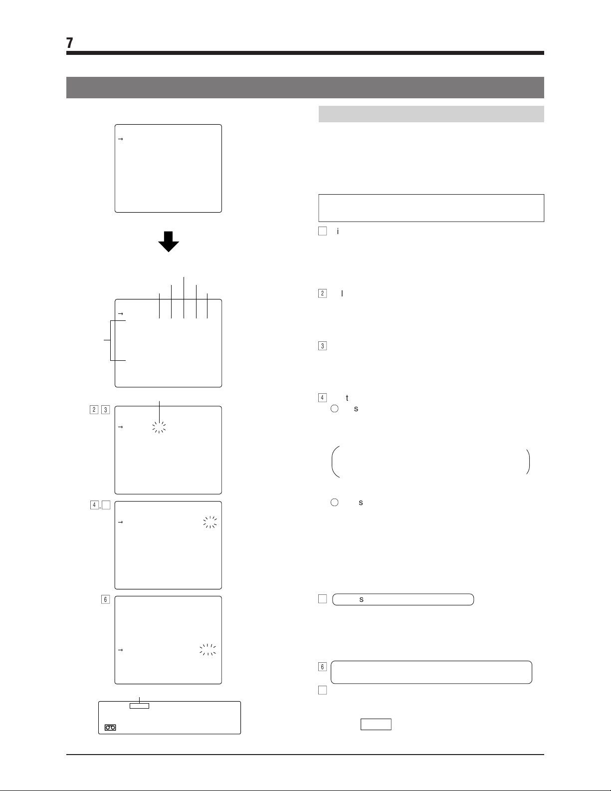
7 RECORDING
7-3 Timer Recording
Days of the
week
(Monday to
Sunday)
2, 3
4
Daily timer program setting screen
PROGRAM TIMER
( DAILY) START END MODE
1. – – – – – – – : – – – – : – – – – H
2. – – – – – – – : – – – – : – – – – H
3. – – – – – – – : – – – – : – – – – H
4. – – – – – – – : – – – – : – – – – H
5. – – – – – – – : – – – – : – – – – H
6. – – – – – – – : – – – – : – – – – H
7. – – – – – – – : – – – – : – – – – H
8. – – – – – – – : – – – – : – – – – H
PRESS (SHIFT, SET, RESET)
PRESS (MENU) TO END
• Set the cursor arrow to the second
line <DAILY> and press the [SET +/] button.
Weekly timer program setting screen
Stop time (hour)
Start time (minute)
Start time (hour)
PROGRAM TIMER
(WEEKLY) START END MODE
( MON ) – – : – – – – : – – – – H
( T UE ) – – : – – – – : – – – – H
( WED ) – – : – – – – : – – – – H
( T HU ) – – : – – – – : – – – – H
( F R I ) – – : – – – – : – – – – H
( S AT ) – – : – – – – : – – – – H
( SUN ) – – : – – – – : – – – – H
PRESS (SHIFT, SET, RESET)
PRESS (MENU) TO END
Blinking
PROGRAM TIMER
(WEEKLY) START END MODE
( MON ) – – : – – – – : – – – – H
( T UE ) – – : – – – – : – – – – H
( WED ) – – : – – – – : – – – – H
( T HU ) – – : – – – – : – – – – H
( F R I ) – – : – – – – : – – – – H
( S AT ) – – : – – – – : – – – – H
( SUN ) – – : – – – – : – – – – H
PRESS (SHIFT, SET, RESET)
PRESS (MENU) TO END
,
5
6
PROGRAM TIMER
(WEEKLY) START END MODE
( MON ) – 8 : 3 0 1 9 : 3 0 12 H
( T UE ) – – : – – – – : – – – – H
( WED ) – – : – – – – : – – – – H
( T HU ) – – : – – – – : – – – – H
( F R I ) – – : – – – – : – – – – H
( S AT ) – – : – – – – : – – – – H
( SUN ) – – : – – – – : – – – – H
PRESS (SHIFT, SET, RESET)
PRESS (MENU) TO END
PROGRAM TIMER
(WEEKLY) START END MODE
( MON ) – 8 : 3 0 1 9 : 3 0 12 H
( T UE ) – 8 : 3 0 1 9 : 3 0 12 H
( WED ) – 8 : 3 0 1 7 : 3 0 – 3 H
( T HU ) – 8 : 3 0 1 9 : 3 0 – 3 H
( F R I ) – 8 : 3 0 2 2 : 3 0 2 4 H
( S AT ) 1 0 : 0 0 2 2 : 0 0 2 4 H
( SUN ) – – : – – – – : – – – – H
PRESS (SHIFT, SET, RESET)
PRESS (MENU) TO END
Stop time (minute)
Record mode
Timer
TIMER
16.30.00
VCR's display
Setting the weekly timer
You can program the VCR to record on a specified day
each week.
Using the same procedure as in daily timer program
setting, select <PROGRAM TIMER> in the main menu to
display the timer program setting screen on the monitor.
(Refer to steps 1 to 3 in daily timer programming.)
• When the timer program setting screen is displayed,
the daily timer program setting screen is shown first.
1
Display the weekly timer program setting screen.
(<WEEKLY> is shown on the second line.)
Press the [SHIFT +] or [SHIFT -] button to move the
cursor arrow to <DAILY> and press the [SET +] or
[SET -] button.
[The weekly timer program setting screen is shown.
2
Select the day of the week you want to record on.
Press the [SHIFT +] or [SHIFT -] button to set the cursor
arrow to the day of the week to be set.
• Press the [SHIFT +] button to move the cursor arrow
down and the [SHIFT -] button to move it up.
3
Set the selected day of the week.
Press the [SET +] or [SET -] button.
[The selected day of the week blinks.
• Press the [SET +] button. The start time (hour) blinks.
• Press the [SET -] button. The record mode blinks.
4
Set the timer.
1
Press the [SHIFT +] or [SHIFT -] button until the item
you want to set starts blinking.
• Press the [SHIFT +] button to shift the blinking to
the right.
"Start time (hour)"
"Stop time (hour)" [ "Stop time (minute)"[
"Record mode" [ Select the next program No.
• Press the [SHIFT -] button to move the blinking to
the left.
2
Press the [SET +] or [SET -] button to set the value
for the blinking item.
• Press the [SET +] button to increase the value and
the [SET -] button to decrease it.
Set the "Start time (hour)", "Start time (minute)", "Stop
time (hour)", "Stop time (minute)" and "Record mode"
with the [SHIFT +/-] and [SET +/-] buttons.
When all values are set, the set program No. is shown
on the VCR's display.
5
Accessing another day of the week.
• Select the "Record mode" (so that it is blinking) and
press the [SHIFT +] button. Or, select "Start time" (so
that it is blinking) and press the [SHIFT -] button.
[The blinking part stops blinking. You may now select
another day of the week.
6
To set more than one weekly timer program, repeat
steps 2 to 5.
7
To end timer programming, press the [MENU] button twice.
[The normal screen is restored.
Press the [TIMER REC] button.
[The TIMER indication lights in the VCR's display.
Power is switched off automatically and the VCR
enters the Timer Record Standby mode.
[ "Start time (minute)" [
30
Page 30

7 RECORDING
7-3 Timer Recording
Setting dates when timer recording is not
executed (cancel program)
Up to 16 days of timer-recorded programming within a year
can be canceled. This function is useful for irregular days
such as holidays, national holidays or special days. This
setting can only be performed when the unit is turned ON.
Cancel program setting screen
PROGRAM TIMER
(CANCEL)
1. 3 0 – 1 0 – – : – –9. – – – – – –
Day
Month
2. – – – – – – – : – 10. – – – – – –
3. – – – – – – – : 11. – – – – – –
4. – – – – – – – : – 12. – – – – – –
5. – – – – – – – : – 13. – – – – – –
6. – – – – – – – : – 14. – – – – – –
7. – – – – – – – : – 15. – – – – – –
8. – – – – – – – : – 16. – – – – – –
PRESS (SHIFT, SET, RESET)
PRESS (MENU) TO END
[MENU] button
COUNT/
CLOCK
TIME
MODE
[TIMER REC] button
[SHIFT–] button
MENU
TIMER
REC
[SET–] button
[SHIFT+] button
SHIFT/TRACKING
SET/V.LOCK
[SET+] button
Canceling timer programming
To stop timer programming
[RESET/CANCEL] button
RESET
/CANCEL
AL/PL
RESET
1
Display the cancel program setting screen.
Set the cursor arrow to the second line (WEEKLY) on
the weekly timer program setting screen, then press the
[SET+] or [SET-] button.
2
Press the [SHIFT+] or [SHIFT-] button to set the cursor
arrow to the number of the day when timer recording is
not to be executed.
3
Engage the Cancel Program Setting mode.
Press the [SET+] or [SET-] button.
When the [SET+] button is pressed, the month blinks.
When the [SET-] button is pressed, the day blinks.
4
Set the data.
Press the [SET+] or [SET-] button to set the value for the
blinking item.
Press the [SET+] button to increase the value and the
[SET-] button to decrease it.
* Set the "Month" and "Day" with the [SHIFT+/-] and
[SET+/-] buttons.
5
To program additional cancel program days, repeat
steps 2 to 4.
6
To quit the Cancel Program Setting mode, press the
[MENU] button twice.
[The normal screen is restored.
1
Press the [RESET/CANCEL] button.
The program being set is canceled.
2
Press the [MENU] button twice.
[The normal screen mode is restored.
To cancel a preset timer program
1
Press the [TIMER REC] button to turn off the TIMER
indication in the display.
2
Turn the VCR and the monitor on.
3
Press the [MENU] button to display the main menu
screen and select <PROGRAM TIMER> with the [SHIFT
+/-] button. Then, press the [SET +/-] button.
[The timer program setting screen is displayed.
4
Press the [SHIFT +/-] button to move the cursor arrow to
the program No. or the day of the week to be canceled.
5
Press the [RESET/CANCEL] button.
[The specified timer program data is canceled.
6
Press the [MENU] button twice.
[The normal screen is restored.
To cancel programmed data
Set the cursor arrow to the desired number and press the
[RESET/CANCEL] button.
31
Page 31

7 RECORDING
7-3 Timer Recording
Changing a preset timer program
1
Press the [TIMER REC] button to turn off the TIMER
indication in the display.
2
Turn the VCR and the monitor on.
3
Press the [MENU] button to display the main menu
screen and select <PROGRAM TIMER> with the [SHIFT
+/-] button. Then, press the [SET +/-] button.
[The timer program setting screen is displayed.
4
Press the [SHIFT +/-] button to move the cursor arrow to
the program No. or the day of the week to be changed.
Press the [SET +/-] button.
5
Select the item to be changed (so that it is blinking) with
the [SHIFT +/-] button.
6
Change the value with the [SET +/-] button.
7
Press the [MENU] button twice.
[The normal screen is restored.
Using the VCR in the Timer Record
Standby mode
Press the [TIMER REC] button to turn off the TIMER
indication for normal use.
Press the [TIMER REC] button again to turn on the TIMER
indication. The Timer Record Standby mode is engaged.
When all timer recording programs have been executed,
the TIMER indication goes off.
Notes on timer recording
If you make a mistake when programming
The TIMER indication blinks and the Timer Record
Standby mode is engaged.
The blinking of the TIMER indication differs depending
on the programming status.
• When correct programs exist, the indication blinks for
about 10 seconds and then lights.
• If mistakes are detected in all programs, the indication
blinks for about 10 seconds.
Incorrect programs are canceled automatically. So, if
necessary, program the timer again.
If no programs have been set
The TIMER indication blinks for about 10 seconds. The
Timer Record Standby mode cannot be engaged.
Program the timer.
If program data overlaps
The Timer Record Standby mode is engaged and the
OVER LAP indication blinks for about 10 seconds.
The OVER LAP indication is not shown, however, if the
DAILY timer program and WEEKLY timer program
overlap.
Check the program contents.
● When program data overlaps, the timer recording
priority is determined as follows.
1
The daily timer has priority over the weekly timer.
2
The program with shorter recording time
(3H>12H>24H>48H>72H>96H>120H>168H>240H)
has priority.
3
The program which starts earlier has priority.
4
When the start time is the same, the program with
the lower program No. has priority.
Priority for the conditions above is in the order of
(1)>(2)>(3)>(4).
During timer recording
The PAUSE/STILL button has no effect.
To operate the VCR, first press the [TIMER REC]
button.
Timer recording
Power is turned on about 20 seconds before recording is
programmed to start and the VCR enters the RecordPause mode. Recording starts about 2 seconds before
the programmed start time.
If no cassette is loaded
The TIMER and (
Load a cassette with safety tab in place. Cassettes with
no tab are ejected.
When the <TAPE END MODE> function menu switch on
the VTR mode 1 setting is set to STOP, REW or EJECT
and the tape ends during timer recording.
The cassette is ejected.
Recording will start again when a cassette with safety tab
in place is loaded.
) indications blink.
32
Page 32

7 RECORDING
7-4 Alarm Recording
Alarm recording functions during timelapse recording. When an alarm signal is input to the rear panel's ALARM IN terminal,
an index code is recorded on the tape and the VCR automatically switches to the VHS Standard (SP) mode for realtime
recording of the alarm situation. Normal timelapse recording is restored after the preset alarm recording duration has passed.
* Alarm recording will not start from the Pause mode.
“AL” indication
PAL
• Set the alarm recording mode, alarm recording duration,
buzzer ON/OFF during alarm recording and the operation
mode at the tape end during alarm recording with the
function menu switches. (Menu switches for alarm/sensor
recording mode setting)
Display "AL"
indication
Record mode
Extinguished
Timelapse
mode
Timelapse
recording
Lit
VHS
Standard (SP)
Alarm
recording
AL
TIME MODE
5 During alarm recording, the AL indication is lit on the
display. After alarm recording is complete, the AL
indication blinks on the display to show that an alarm
signal has been input.
Blinking
Timelapse
mode
Timelapse
recording
Lit
VHS
Standard (SP)
Alarm
recording
Blinking
Timelapse
mode
Timelapse
recording
Alarm signal input
* An index code (VISS) is recorded at the start point of the alarm recording as an alarm cue signal.
* During alarm recording, a +12 V signal is output from the rear panel’s ALARM REC OUT terminal.
Alarm signal input
33
Page 33

7 RECORDING
7-4 Alarm Recording
Preparation
1
Press the [OPERATE] button to turn the operating mode
Connect an alarm sensor to the rear panel’s alarm input terminal.
on.
Setting the function menu switches for the Alarm
Record mode
2
Press the [MENU] button to display the main menu
screen on the monitor.
3
Press the [SHIFT +/-] button to select <FUNCTION> and
press the [SET +/-] button.
[The function menu switch setting screen is
displayed.
4
Press the [SHIFT +/-] button to display the alarm/sensor
recording mode setting screen.
5
Select the item to be set with the [SHIFT +/-] button. Set
the value with the [SET +/-] button.
• Set <ALARM REC> to ON to activate the alarm
recording function. The AL REC indication in the
display lights.
• Set the alarm recording duration.
Set duration to 5 sec., 15 sec., 30 sec., 60 sec.,
120 sec., 180 sec., TAPE END or MANUAL (for as
long as alarm signals are input).
* When the alarm recording time is set to MANUAL,
the alarm cue signal (index code) will not be
recorded correctly if alarm input lasts for less than
30 seconds.
* When alarm recording duration is set with an
external switcher, set the alarm recording duration
to MANUAL.
• To sound the buzzer during alarm recording, set
<BUZZER> to ON.
• Set the operation mode at tape end in the case when
alarm recording is executed even once with the menu
switch <TAPE END MODE> on the alarm/sensor
recording mode setting screen.
STOP : The tape stops.
REW : The tape is rewound to the beginning and
stops.
REPEAT : Recording continues from the beginning of
the tape.
EJECT : The tape is ejected.
6
After setting the function menu switches, press the
[MENU] button twice.
[The normal screen is restored.
A LARM / SENSOR REC MODE
Alarm recording function
Alarm recording duration
Buzzer
Tape end mode
7
Select the timelapse recording mode with the
(ALARM REC) ON
(SENSOR REC) OFF
(DURATION) 180SEC
(BUZZER) OFF
(TAPE END MODE) STOP
PRESS (SHIFT, SET)
PRESS (MENU) TO END
Alarm/sensor recording
mode setting screen
[TIME MODE] button on the front panel.
[ The selected recording mode is shown on the VCR's
display and the on-screen display.
8
Follow the procedures for "Recording" on page 27.
9
When an alarm signal is input to the rear panel's
ALARM IN terminal, alarm recording is executed as
specified.
0
To stop alarm recording and clear the alarm indication,
press the [AL/PL RESET] button.
• When the AL indication is lit on the display (during
alarm recording), press the [AL/PL RESET] button to
stop alarm recording. Timelapse recording is resumed
and the AL indication goes out. If the alarm buzzer is
on, it stops as well.
• When the AL indication is blinking on the display,
press the [AL/PL RESET] button. The AL indication
goes out.
!
When the AL indication goes out, press the [AL/PL
RESET] button again to reset the alarm input/power loss
data.
* There may be some picture distortion at the start or
end of an alarm recording. This is not a malfunction.
Check the time and data shown on the monitor's onscreen display.
If the time and date are not shown on the monitor or if
you want to change the display position, use the
<POSITION> function menu switch.
34
Page 34

7 RECORDING
7-5 Sensor Recording
Sensor recording is executed only when the VCR is in the Stop mode (Stop or Timer Record Standby mode) and an alarm
signal is input to the rear panel’s ALARM IN terminal.
Perform the settings for sensor recording in the same way as for "Alarm Recording" on page 33.
The mechanism of the SR-9240E/EK cannot be guaranteed if the sensor recording function is used frequently (100 times/
day or more). If alarm inputs are frequent, use the alarm recording function instead and carry out regular maintenance/
inspection and parts replacement.
Preparation
1
Press the [OPERATE] button to turn the operating mode
Connect an alarm sensor to the rear panel’s alarm input terminal.
on.
Setting the function menu switches for the Sensor
Record mode
2
Press the [MENU] button to display the main menu
screen.
3
Press the [SHIFT +/-] button to select <FUNCTION>
and press the [SET +/-] button.
[ The function menu switch setting screen is
displayed.
4
Press the [SHIFT +/-] button to display the alarm/sensor
recording mode setting screen.
5
Select the item to be set with the [SHIFT +/-] button. Set
the value with the [SET +/-] button.
• Set the <SENSOR REC> to ON to activate the sensor
recording function. The SENSOR REC indication in
the display lights.
• Set the sensor recording duration.
Set <DURATION> to 5 sec., 15 sec., 30 sec., 60 sec.,
120 sec., 180 sec., TAPE END or MANUAL (for as
long as alarm signals are input).
* The sensor recording time will be shorter than the
specified value.
* When the sensor recording time is set to MANUAL,
the alarm cue signal (index code) will not be
recorded correctly if alarm input lasts for less than
30 seconds.
* When sensor recording duration is set with an
external switcher, set the sensor recording duration
to MANUAL.
• To sound the buzzer during sensor recording, set
<BUZZER> to ON.
• Set the operation mode at tape end in the case when
sensor recording is executed even once with the menu
switch <TAPE END MODE> on the alarm/sensor
recording mode setting screen.
STOP : The tape stops.
REW : The tape is rewound to the beginning and
stops.
REPEAT: Sensor recording continues from the
beginning of the tape.
EJECT : The tape is ejected.
Sensor recording function
Sensor recording duration
Buzzer
Tape end mode
6
After completing function menu switch setting, press the
A LARM / SENSOR REC MODE
(ALARM REC) OFF
(SENSOR REC) ON
(DURATION) 180SEC
(BUZZER) OFF
(TAPE END MODE) STOP
PRESS (SHIFT, SET)
PRESS (MENU) TO END
Alarm/sensor recording
mode setting screen
[MENU] button twice.
[ The normal screen is restored.
Check the time and data shown on the monitor's onscreen display.
If the time and date are not shown on the monitor or if
you need to change the display position, use the
<POSITION> function menu switch.
7
• When an alarm signal is input to the rear panel's
ALARM IN terminal, recording starts automatically in
the specified record mode and the AL indication is lit.
• After the specified recording duration expires,
recording stops and the Stop mode is engaged.
* Because sensor recording starts from the Stop
mode, it takes several seconds from the time an
alarm input is received to the time recording actually
starts.
8
To stop sensor recording and clear the AL indication,
press the [AL/PL RESET] button.
9
To disable sensor recording, set menu switch
<SENSOR REC> to OFF.
During playback, there may be some noise or picture
distortion at the point where one sensor recording
stops and another starts. This is not a malfunction.
35
Page 35

7 RECORDING
7-6 Repeat Recording
When the tape reaches the end during recording, it is automatically rewound and recording starts again from the beginning.
5 To execute repeat recording, set <TAPE END MODE>
on the VTR mode 1 setting screen to REPEAT.
Setting the function menu switch <TAPE END MODE>
5
on the alarm/sensor recording mode setting screen
• When the tape ends during recording in the case when
alarm or sensor recording is executed even once, the
tape stops or rewinds and stops at the beginning if this
menu switch set to “STOP” or “REW”,.
If this menu switch is set to "EJECT", the tape is
ejected.
To continue repeat recording even when alarm/
sensor recording is executed, set this menu
switch to “REPEAT” .
Auto recording
check function
Tape end mode
PRESS (SHIFT, SET)
PRESS (MENU) TO END
VTR mode 1 setting screen
* When repeat recording is performed, the previously-
recorded alarm recording is erased.
VTR MODE 1
(SHARPNESS) NORMAL
(VIDEO MODE) AUTO
(AUTO REC) OFF
(REC CHECK) AUTO
(TAPE END MODE) REPEAT
(INDEX SEARCH) OFF
(CAMERA SW) OFF
(TAPE END BUZZER) OFF
(WARNING BUZZER) OFF
Set to
REPEAT
Auto Recording Check function
This function automatically checks recording quality at
the beginning of the tape during repeat recording.
• To activate the Auto Recording Check function, set the
<REC CHECK> function menu switch in the VTR mode 1
setting screen to AUTO.
Operation of the Auto Recording Check function
• The recorded section at the beginning of the tape is
automatically played back in the Repeat Record mode
and the FM level recorded on the tape is checked. If
the level is satisfactory, recording continues.
• If recording quality is deemed inferior, the heads are
cleaned automatically. After several seconds of
recording, the recording state is checked again.
If recording quality is still unsatisfactory after two
consecutive checks, the error indicator E-09 is shown
in the display and recording continues.
Function menu switch <REC CHECK> set to AUTO
Repeat recording
Beginning of
the tape
Recording
check
Defective
Auto head
cleaning
Auto recording
for several
seconds
Normal
Recording
check
Defective
Display
Error indicator E-09 display
Recording
Normal
Auto head
cleaning
Recording
Recording
36
Page 36

7 RECORDING
7-7 Series Recording
The series recording function facilitates recording over much longer periods using several connected SR-9240E/EKs.
As soon as the tape ends in one VCR, the next VCR in the series starts recording.
Connections
5 Connect the first VCR’s [SERIES/CLOCK OUT] terminal
to the second VCR’s [SERIES/CLOCK IN] terminal.
Connect the second VCR’s [SERIES/CLOCK OUT]
terminal to the third VCR’s [SERIES/CLOCK IN]
terminal. Repeat for all connected VCRs. Connect the
VCR’s [COM] terminals as well.
5 Connect a video camera and/or other source equipment
to the first VCR’s video and audio input connectors.
Connect the first VCR’s video and audio output
connectors to the second VCR’s video and audio input
connectors. Connect the second VCR’s video and audio
output connectors to the third VCR’s video and audio
input connectors. Repeat for all connected VCRs.
Connect the last VCR’s video and audio output
connectors to the monitor’s video and audio input
connectors.
Video input signal
Rear
panel
First VCR
Audio input signal
IN
OUT
IN
OUT
Rear panel
SERIES/CLOCK
COM
IN OUT
First VCR Second VCR Third VCR
COM
SERIES/CLOCK
IN OUT
COM
SERIES/CLOCK
Operations
1
Set the <TERMINAL SEL 1> function menu switch on
the VTR mode 2 setting screen to “SERIES” (series
recording) for all connected VCRs.
VTR MODE 2
(SUMMER TIME) OFF
TERMINAL
SEL 1
REC
REMAIN
(TERMINAL SEL 1) SERIES
(TERMINAL SEL 2) WARN
(REC REMAIN)) OFF
(COUNT END) OFF
PRESS (SHIFT, SET)
PRESS (MENU) TO END
Set to
SERIES
VCR mode-2
setting screen
IN OUT
Second VCR
• Output a series recording signal from the [SERIES/
CLOCK OUT] terminal to start recording. Set the
signal output timing with <REC REMAIN> or <COUNT
END>. For details, refer to "Contents of the Function
Menu Switches" on page 21.
2
To end function setting, press the MENU button to close
the menu display and restore the time/date display.
3
Load cassettes with safety tab in place in all connected
VCRs.
4
Engage the Record mode on the first VCR.
Turn on all connected VCRs and put them in the
Standby mode. This allows you to check picture and
sound on the monitor.
Last VCR
Video output
IN
OUT
Audio output
When the recording is complete on the first VCR, the
second VCR automatically starts recording. This is
repeated for all connected VCRs.
Monitor TV
Note
• If a cassette has not been loaded in any VCR in the series, series recording will stop when that VCR is reached.
37
Page 37

7 RECORDING
7-8 Recording with External VCR Activation Signal
Recording start/stop can be controlled externally by inputting a VCR activation signal to the [SERIES/CLOCK IN] terminal on
the SR-9240E/EK’s rear panel.
Rear panel
To [SERIES/CLOCK IN] terminalTo [COM] terminal
External control
equipment
Connection
VCR control signal (ground signal)
LV: 0 V
Start of recording
Stop or power off
Operation
VTR MODE 2
(SUMMER TIME) OFF
TERMINAL
SEL 1
• This function has no effect in the Timer Record
Standby mode.
• If a VCR activation signal is input while the unit is
already recording (started with the [REC] button),
recording continues and stops when the activation
signal is no longer input.
(TERMINAL SEL 1) EXT
(TERMINAL SEL 2) WARN
(REC REMAIN)) OFF
(COUNT END) OFF
PRESS (SHIFT, SET)
PRESS (MENU) TO END
VTR mode 2 setting screen
Set to EXT.
(External
recording
function)
Connect the [SERIES/CLOCK IN] terminal and [COM]
terminal on the SR-9240E/EK’s rear panel to the external
control equipment.
1
Set the function menu switch <TERMINAL SEL 1> on
the VTR mode 2 setting screen to “EXT” to use the
external recording function.
2
Press the MENU button to switch the on-screen display
to the time/date display.
3
Load a cassette with a safety tab in place and engage
the Stop mode, the Pause mode or turn the operating
mode off.
• When a VCR activation signal (ground input) is input to
the rear panel’s [SERIES/CLOCK IN] terminal,
recording starts automatically and continues for as
long as the activation signal is input.
When the activation signal stops, the Stop or Pause
mode is engaged or the operating mode is turned off
(depending on the VCR status before the external
recording function is used).
• When the activation signal is input again, recording
starts.
38
Page 38

7 RECORDING
7-9 How to Restore Recording After Power Failure
If a power failure occurs during recording, recording will
restart in the same mode as soon as power is restored.
To use this function, set the function menu switch <AUTO
REC> on the VTR mode 1 setting screen to ON.
* If this function menu switch is set to ON and power is
turned off and on again in the Stop mode, the VCR
enters the Record mode automatically. Be careful.
AUTO REC
(SHARPNESS) NORMAL
(VIDEO MODE) AUTO
(AUTO REC) ON
(REC CHECK) MANUAL
(TAPE END MODE) REPEAT
(INDEX SEARCH) OFF
(CAMERA SW) OFF
(TAPE END BUZZER) OFF
(WARNING BUZZER) OFF
PRESS (SHIFT, SET)
PRESS (MENU) TO END
VTR mode 1 setting screen
7-10 External Timer Recording
External timer recording can be performed by connecting the SR-9240E/EK to an external timer.
1
Check that a cassette is loaded in the VCR.
* If the cassette’s safety tab has been removed,
recording will not take place.
* This function does not work when the Timer Record
mode is engaged.
2
Set the function menu switch <AUTO REC> to ON.
Power is supplied from the external timer at the
specified time and recording starts.
VTR MODE 1
Set to
ON
7-11 Tape End Buzzer
When set to ON, a buzzer sounds when the tape ends
during recording. To set the buzzer sound on, set the
function menu switch <TAPE END BUZZER> to ON.
5 Set the timing for the buzzer with <REC REMAIN> or
<COUNT END>. For details, refer to "Contents of the
Function Menu Switches" on page 21.
5 To stop the buzzer sound, you can set the <TAPE END
BUZZER> function menu switch to OFF, turn off the
power, or press another operation button.
5 During repeat recording and AUTO REW, the buzzer
sounds for about 2 seconds.
TAPE END
BUZZER
VTR MODE 1
(SHARPNESS) NORMAL
(VIDEO MODE) AUTO
(AUTO REC) ON
(REC CHECK) MANUAL
(TAPE END MODE) REPEAT
(INDEX SEARCH) OFF
(CAMERA SW) OFF
(TAPE END BUZZER) ON
(WARNING BUZZER) OFF
PRESS (SHIFT, SET)
PRESS (MENU) TO END
VTR mode 1 setting screen
Set to
ON
39
Page 39

8 PLAYBACK AND SPECIAL-EFFECTS PLAYBACK
[STOP/EJECT] button
[PLAY] button
Playback mode
indication
8-1 Preparation
Connection
Make sure the output connectors on the rear panel are
properly connected.
Function menu switch settings
Set the function menu switches as required.
5 [SHARPNESS] . . . Factory setting: NORMAL
Set to SHARP to emphasize contours for sharper
playback pictures.
5 [INDEX SEARCH] . . . Factory setting: OFF
To enable or disable index search.
• Set to ON to search the alarm-recorded positions
(index code).
[OPERATE] button
PAL
[TIME MODE] button
8-2 Playback
1
Press the [OPERATE] button to turn the operating mode
on.
[ The [OPERATE] indicator lights.
2
Press the [TIME MODE] button to set the Play mode to
the VHS Standard (3H).
The 3H indicator is shown on the display.
• To use playback in the Timelapse Play mode, make
sure the same mode (L12H or L24H) is set for
playback as was used for timelapse recording.
3
Load the recorded cassette correctly.
* If a cassette is loaded when the power is off, power is
switched on automatically (auto-power on function).
If the cassette's safety tab has been removed, power is
switched on and play starts automatically (auto play
function).
4
Press the [PLAY] button to start play.
The play indicator is shown on the display and
the Play mode is engaged.
Notes
• When a tape recorded in the VHS standard
(3H) mode is played back in the Timelapse
mode, noise appears in the playback picture.
• Tapes recorded in the Long Play (LP) mode
can be played back only.
Still, Reverse Play and Shuttle Search modes
are not available with LP tapes.
Menu check during playback
• When the [MENU] button is pressed during
playback, the monitor screen display switches from
the playback picture to the input video signal (EE
picture) and the main menu is shown on the screen.
This means that even during playback you can
check menu contents.
Press the [MENU] button again to restore the
playback picture.
40
• Cassettes recorded in the VHS Long Play mode
(LP) are played back in the VHS Long Play mode.
• "006H" is shown in the display.
To stop playback
5
Press the [STOP] button.
The tape stops and the Stop mode is engaged.
Audio playback of a timelapse-recorded tape
• Due to the difference in tape speed, audio signals
cannot be monitored when a tape recorded in the
L12H or L24H Timelapse mode is played back in the
VHS Standard (3H) mode.
To monitor audio recorded in the Timelapse mode,
play back the tape in the same mode (L12H or L24H)
as it was recorded in.
Page 40

8 PLAYBACK AND SPECIAL-EFFECTS PLAYBACK
[REVERSE] button
[PLAY] button
PAL
[REW] button
[FF] button
[PAUSE/STILL] button
8-3 Special-Effects Playback
Still and field/frame advance
1
Press the [PAUSE/STILL] button during playback.
The still indicator is shown on the display and a
still picture is displayed.
2
Each time the [PAUSE/STILL] button is pressed in the
Still mode, the picture is advanced one field.
3
Press the [PLAY] button to restore the Normal Play
mode.
The Stop mode is automatically engaged if the VCR
remains in the Still mode for 5 minutes (approx.).
Shuttle search (reverse and fast-forward) playback
Reverse playback
1
Press the [REVERSE] button in the Play or Still mode.
The reverse indicator is shown on the display
and the Reverse mode is engaged.
Reverse playback is executed at VHS SP mode speed.
When the play time mode is set to 3H,L12H or L24H,
reverse playback is executed at the VHS SP mode’s
speed.
* No sound is output.
2
To return to the Normal Play mode, press the [PLAY]
button.
Reverse shuttle search
Press the [REW] button during play.
The rewind search indicator is shown on
the display and the Reverse Shuttle
Search mode is engaged.
* No sound is output.
Shuttle search operations vary according to how the [REW] or [FF] button is pressed. Refer to the table below for details.
Operation of the [REW] or
[FF] button
Press the button once.
Hold the button pressed
for more than 2 seconds.
Tape recorded in the Standard mode or the Timelapse mode
9 times normal speed (lock). Pressing the [PLAY] button restores the Normal Play mode.
9 times normal speed. Releasing the finger restores the Normal Play mode.
Press the [FF] button during playback.
Fast-forward shuttle search
The fast-forward search indicator is shown
on the display and the Fast-Forward
Shuttle Search mode is engaged.
* No sound is output.
Note
Still and Reverse Play modes are not available with tapes recorded in the Long Play (LP) mode.
41
Page 41

8 PLAYBACK AND SPECIAL-EFFECTS PLAYBACK
8-4 Index Search
Searching the index code (VISS signal) recorded at the
start of alarm recording helps you quickly locate alarm
recordings (index search function).
• To use the index search function, set the function menu
switch [INDEX SEARCH] to ON.
VTR MODE 1
(SHARPNESS) NORMAL
(VIDEO MODE) AUTO
(AUTO REC) OFF
(REC CHECK) MANUAL
(TAPE END MODE) STOP
INDEX
SEARCH
(INDEX SEARCH) ON
(CAMERA SW) OFF
(TAPE END BUZZER) OFF
(WARNING BUZZER) OFF
PRESS (SHIFT, SET)
PRESS (MENU) TO END
Set to
ON
VTR mode 1 setting screen
8-5 Tracking/V. Lock Adjustment
5 When reverse shuttle search or fast-forward shuttle
search is executed, the Index Search mode is engaged.
When an index code is located, playback starts
automatically.
To engage the Reverse Shuttle Search mode or the
Fast-Forward Shuttle Search mode, press the
[REW] or [FF] button once during playback.
5 When an index code is searched in the Fast-Forward
mode or the Rewind mode, the Stop mode is
automatically engaged when the code is located.
• The VISS indicator is shown on the display whenever
the Index Search mode is engaged.
Index Search does not function in the Auto Rewind
mode.
[TRACKING +/-] button
When noise appears in the picture in the Play/
Field Advance Play/Search mode
Tracking can only be adjusted in the following modes:
• VHS Standard (3H) Play and Long Play (LP)
• Field Advance Playback with the [PAUSE/STILL]
button
• Search mode
Press the [TRACKING +/-] button to reduce noise.
To restore the tracking preset mode, press the + and -
buttons simultaneously.
* Tracking adjustment cannot be performed in the
Timelapse Play modes.
PAL
[V. LOCK +/-] button
When the picture moves up and down in the
Still mode
Press the [V. LOCK +/-] button to minimize vertical jitter.
42
Page 42

VTR MODE 1
(SHARPNESS) NORMAL
(VIDEO MODE) AUTO
(AUTO REC) OFF
(REC CHECK) MANUAL
(TAPE END MODE) REPEAT
(INDEX SEARCH) OFF
(CAMERA SW) OFF
(TAPE END BUZZER) OFF
(WARNING BUZZER) ON
PRESS (SHIFT, SET)
PRESS (MENU) TO END
9 TROUBLESHOOTING
9-1 Error Indication
Error indications are shown on the display whenever there
are problems with cassette loading, unloading or
mechanism operation.
Display section
5 When a problem occurs, the error indication E-
– –
blinks.
5 When any one of the error indications is shown, a 12 V
warning signal is output from the rear panel's WARNING
OUT connector (for E-01 to E07, and E-11 during
recording) (only when the <TERMINAL SEL 2> menu
function switch is set to "WARN").
5 When the function menu switch <WARNING BUZZER>
is set to ON, the buzzer sounds whenever a problem
occurs (for E-01 to E07, and E-11 during recording).
When an error indication appears or the buzzer
sounds, turn the operating mode off and then on again
to clear the error indication and buzzer sound.
When the error indication Eoperating mode on again may not clear the problem. In
this case, consult your local JVC dealer (for E-01 to E-
07).
Error
Contents
indication
E-01
E-02
E-03
E-04
E-05
E-06
E-07
E-09
Problem with loading operation
Problem with unloading operation
Problem with supply reel rotation
Problem with drum rotation
Problem with take-up reel rotation
Problem with capstan rotation
Problem with eject operation
Error with recording check
(inferior recording performance)
is shown, turning the
– –
The operating mode is turned off.
The operating mode is turned off.
The operating mode is turned off.
The operating mode is turned off.
The operating mode is turned off.
The operating mode is turned off.
The operating mode is turned off.
Cleans the heads with the VCR's
head cleaner.
Buzzer sound
VCR operation
TIME MODE
Error indication
VTR mode 1 setting screen
Measures
Turn the operating mode on again.
Turn the operating mode on again.
Turn the operating mode on again.
Turn the operating mode on again.
Turn the operating mode on again.
Turn the operating mode on again.
Turn the operating mode on again.
Cleans the heads with the head
cleaning tape, then check the
recording picture quality again. The
tape may be defective. Replace the
tape and check again.
If the picture quality is still inferior,
consult your local JVC dealer.
E-10
E-11
This unit uses a microprocessor and may not function properly if there is external noise or interference. In this case, turn
the operating mode off and unplug the power cord from the AC outlet. Then plug the power cord in again and check
operation.
Insufficient capacity of the built-in
battery for backup (Displayed
only in the operating off mode.)
No video signals input to the
[VIDEO IN] connector
For servicing
→
See page 1-10 “1.7 WARNING DETECTION CIRCUIT”
—
—
Contact your local JVC dealer to
replace the built-in battery.
Input video signals.
43
Page 43

9 TROUBLESHOOTING
9-2 No Error Indication
Symptoms
No power is supplied.
Operation buttons have no effect
during recording and playback.
No picture is shown during
playback.
Noise appears in the picture in
the Shuttle Search mode and
Still mode.
Noise appears in part of the
playback picture.
When the cassette is played
back, the picture becomes rough
or disappears.
During playback, sound is highpitched and hard to hear.
Recording is impossible.
Timer recording is not working.
The clock cannot be set.
Tape running sound is heard in
the Record, Play, FF and REW
modes.
The time/date is not shown.
During recording, repeat
recording does not take place.
Causes
q Is the power cord disconnected?
q Is the TIMER indication shown?
q Is the Operation Lock mode
engaged?
Is the Operation Lock mode
engaged?
Is the monitor connected correctly?
This is not a malfunction.
q Is the tracking adjusted properly?
q Are you playing back a tape
recorded in the VHS SP (3H)
mode in the Timelapse mode?
In this case, noise appears in the
playing picture.
Dust may have accumulated on the
video heads.
Are you playing back a tape
recorded in the 12H or 24H
Timelapse mode in the VHS
Standard (3H) mode? In this case,
sound is high-pitched.
Has the cassette safety tab been
removed?
q Is the clock set correctly? Is the
timer properly programmed?
q Is the TIMER indication lit?
Is the TIMER indication lit?
This is normal.
q Is the clock set?
q Is the <POSITION> function
menu switch set to OFF?
Is the function menu switch <TAPE
END MODE> in the alarm/sensor
recording mode setting screen set to
STOP, EJECT or REW?
If so, when the tape ends during
recording in the case when alarm
recording is executed even once, it
stops or is rewound to the beginning
and stops.
Remedies
q Connect the power cord to an AC
outlet.
q Press the TIMER REC button so that
the TIMER indication goes out.
q Release the Operation Lock mode.
Release the Operation Lock mode.
Connect the monitor correctly.
—
Adjust the tracking with the
[TRACKING+/–] button.
Tracking adjustment is not possible in
the Timelapse Play mode.
Clean the video heads. Consult your
nearest JVC dealer.
Play back the tape in the same mode
(12H or 24H) as that used for recording.
Paste a piece of cellophane tape over
the hole.
q Check again.
q Check it again.
Press the TIMER button so that the
TIMER indication goes out.
If you feel it is too noisy, install the VCR
in a rack.
q Set the clock.
q Set the <POSITION> function menu
switch to another position.
To continue repeat recording even when
the alarm recording is executed, set the
function menu switch <TAPE END
MODE> on the alarm/sensor recording
mode setting screen to REPEAT.
Camera image is not switched.
44
Is the <CAM SW> function menu
switch set to "OFF"?
When setting the camera switching
timing, set it to "1 FIELD" or "1 FRAME".
Page 44
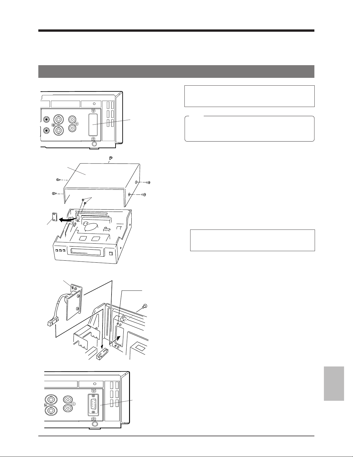
10. OPTIONAL SA-K97U RS-232C INTERFACE BOARD
Functions that can be controlled with front panel buttons and switches can also be controlled from a personal computer when
the optional SA-K97U RS-232C interface board is installed. Operation status can also be monitored on the computer.
10-1. Installation of the SA-K97U
MIC
IN
REMOTE
Top cover
Plate
VIDEO
AUDIO
IN IN
OUT
Rear panel
OUT
Screws
SA-K97U
installation
section
The procedure is shown below. However, to avoid
electric shock or injury, contact your local JVC
service center for details.
Note:
When installing this board, be careful not to injure
yourself on sharp edges and metal parts inside
the VCR.
Before installing the board, turn the power off and unplug
the power cord from an AC outlet.
1. Detach the top cover.
Remove the 5 screws securing the top cover and lift it off.
2. Detach the plate in the VCR.
Remove the 2 screws on the rear panel. Detach the plate
from the inside of the VCR.
3. Connect the SA-K97U’s connector to the VCR.
Insert the SA-K97U connector into the connector (CN607)
on the board in the VCR using a tool such as a pincette.
• During insertion, make sure the connector is aligned
properly.
• Press both edges of the connector to insert it securely.
Positioning
holes
(2 positions)
VIDEO
IN IN
OUT
SA-K97U
RS-232C board
AUDIO
OUT
Projection sections
(2 positions)
CN607
Screws (2)
SA-K97U
4. Install the SA-K97U in the VCR.
Make sure the SA-K97U bracket is facing the correct
direction and align the positioning holes on the bracket
with the projections (2 positions) on the VCR’s case.
Secure the bracket with the 2 screws removed in step 2.
5. Attach the top cover as before.
Attach the top cover to the VCR using the 5 screws
removed in step 1.
Make sure you use the correct screws.
45
Page 45

10. OPTIONAL SA-K97U RS-232C INTERFACE BOARD
10-2. SA-K97U Specifications
9-pin connector specifications
Pin NO. Signals Operations Direction of signals
2 RXD Receive data VTR p CPU
3 TXD Transmit data VTR [ CPU
4 DTR Data terminal ready VTR [ CPU
5 GND Signal ground
6 DSR Data set ready VTR p CPU
Output level
ON : +5 V or more
Data format
OFF: –5 V or less
6
9
1
2
3
4
5
5 Mode :
5 Character length :
5 Data rate :
5 Parity check :
5 Stop bit :
Non-synchronized
8 bits
1200, 2400, 4800, 9600 bps
(switched with function menu switch, set to 9600 bps before shipment)
No
1 bit
10-3. SA-K97U RS-232C Protocol & Commands
RS-232C protocol
JVC table-1
0123 4 5 6 7 8 9A B C D E F
0 Data “0” ENTER TIMER ON SCREEN VISS FRAME CODE
1 COMPLE- Data “1” CLEAR TIMER ON SCREEN VISS REC DEVICE AL . PL
TION ERROR OFF OFF REV CHECK TYPE RESET
2 ERROR Data “2” PRG/CLK ROM VER HOUR METER COUNT
3 CASSETTE Data “3” SHFT+ EJECT SEARCH
OUT (VISS)
4 Data “4” SHFT– ON SCREEN
5 NOT Data “5” SET+ PL .AL COUNT
TARGET SENSE
6 ALARM Data “6” CLEAR SET– TL STATUS TL STATUS JVC
INPUT SET SENSE TABLE1 ON
7 Data “7” CANCEL STATUS JVC
8 Data “8”
9 Data “9” OPE LOCK
A ACK PLAY REV OPE LOCK REC REC
B NAK
C
D MODE F-FIELD
E MODE DATE SET DATE S
F STOP STILL TIME SET TIME S
Functions in the shaded section are effective only when JVC table-1 is set to ON.
ON ON FWD (COUNT)
SENSE RESET
SELECT
SENSE TABLE1 OFF
ON
PLAY OFF REQUEST
OPERATE ON
OPERATE OFF
SHIFT STEP
FF REC VTR INQ
REW
PAUSE
46
Page 46

10. OPTIONAL SA-K97U RS-232C INTERFACE BOARD
10-3. SA-K97U RS-232C Protocol & Commands
This section provides technical data for programmers.
Command description
To use the commands described in the following pages, prepare the VCR for communications as follows:
Transmit the command “JVC TABLE 1 ON” (F6H) to the VCR. The VCR will return “ACK” (0AH).
The VCR can now receive any command described in this section. To cancel the communications mode, transmit the command “JVC
TABLE 1 OFF” (F7H).
2-1 VCR control commands
Commands (1) through (12) are 1-byte commands. The VCR will return “ACK” (0AH) when the command is received. Confirm that “ACK”
(0AH) has been returned before transmitting the next command.
(1) OPERATE ON (7BH) : VCR operating mode is turned “ON”.
OPERATE OFF (7CH) : VCR operating mode is turned “OFF”.
(2) PLAY (3AH) : Playback
(3) STILL (4FH) : Pause/Still
(4) STOP (3FH) : Stop
(5) FF (ABH) : FF/Forward search in the Play mode. (INDEX Search when Menu switch <INDEX SRCH> is set to
(6) REW (ACH) : REW/Reverse search in the Play mode. (INDEX Search when Menu switch <INDEX SRCH> is set
(7) REV PLAY (4AH) : Reverse playback at normal speed
(8) TIMER ON (60H) : Timer “ON”
TIMER OFF (61H) : Timer “OFF”
(9) OPE LOCK ON (69H) : Operation lock “ON”
OPE LOCK OFF (6AH) : Operation lock “OFF”
(10) EJECT (A3H) : Cassette ejection
(11) F-FIELD STEP (ADH) : Engages field advance when the VCR is in the Still mode. The tape is advanced by one field in the
(12) REC CHECK (C1H) : Engages REC CHECK. (function is the same as when locally controlled on the VCR.)
ON.)
to ON.)
VCR returns “ACK”, and then returns CASSETT OUT (03H) after cassette has been ejected.
3H/Timelapse mode.
If the VCR is in any other mode, the Still mode is engaged.
Before transmitting either of the following commands ((13) or (14)), first transmit REC/DUB REQUEST (FAH), and confirm that “ACK” is
returned by the VCR.
(13) REC (CAH) : Starts recording. The VCR returns “ACK”.
(14) REC PAUSE (CBH) : Engages Record-Pause mode. The VCR returns “ACK”.
However, if the loaded cassette’s safety tab has been removed, recording is not possible regardless of the fact that “ACK” has been
returned. Use the STATUS SENSE (D7H) command to confirm tape status. (See Section 2-3 (9)).
After transmitting commands VISS FWD (15) or VISS REV (16), transmit the appropriate numeric data (1-byte ASCII codes from 30H to 39H)
and the data input command (40H).
ASCII codes “30H – 39H” correspond with the numbers “0 – 9” (ie.: 0: 30H, 1: 31H, ... 9: 39H).
Each byte of numeric data and the data input command should be transmitted separately with “ACK” (0AH) confirmation from the VCR after
each transmission. The VCR’s Menu switch <INDEX SRCH> is set to OFF.
(15) VISS FWD (B0H) : To advance the tape in the forward search mode to the designated alarm-input point. The alarm
(16) VISS REV (B1H) : To reverse the tape in the reverse search mode to the designated alarm-input point. The alarm
Eg: To search for the 3rd alarm-input point from the current position.
TXD
RXD
The VCR starts INDEX search after returning “ACK”. When the specified point is reached, the VCR returns COMPLETION (01H). If the end
or beginning of the tape is reached before the specified point, the VCR returns NOT TARGET (05H). (Sending either the 30H,30H or
30H,31H command will cause the VCR to search for the 1st alarm-input point).
B0H 33H 40H
30H
0AH 0AH 0AH 01H (or 05H)
• To re-start recording, transmit REC (FAH+CAH).
• To cancel Record-Pause, transmit STOP (3FH). The VCR will enter the Stop mode.
point’s 2-byte numeric data should be input after transmission of this command.
point’s 2-byte numeric data should be input after transmission of this command.
0AH
Search start
Time
47
Page 47

10. OPTIONAL SA-K97U RS-232C INTERFACE BOARD
TXD
86H 1st byte
0AH 0AH
Time
2nd byte
0AH
3rd byte
0AH
RXD
After transmitting the VISS SEARCH command (17), transmit the appropriate 2-byte numeric data (from 30H to 39H), the data input command
(40H), and either FF (ABH) or REW (ACH). All commands should be transmitted separately one byte at a time with “ACK” (0AH) confirmation
from the VCR after each transmission.
(17) VISS SEARCH (B3H) : To search for a designated INDEX point on the tape.
The VCR starts INDEX search after returning “ACK”. When the specified point is reached, the VCR returns COMPLETION (01H). If the end
or beginning of the tape is reached before the specified point, the VCR returns NOT TARGET (05H).
This command differs from commands (15) and (16) only in that the FF (ABH) or REW (ACH) command is included separately.
2-2 VCR setting commands
Commands available include control of recording/playback mode setting, timelapse VCR operation mode setting, date and time setting, timer
programming, on-screen setting, and others.
5 Recording/playback mode setting commands
Two commands are available. One allows you to rotate through recording/playback modes, the other permits you to directly select the
mode.
(1) MODE SHIFT (7DH) :Switches from one recording/playback mode to the next each time
(2) MODE (7EH) :Sets recording/playback mode directly.
Eg: To set to “L24H”.
TXD
RXD
5 Timelapse VCR operation mode setting commands
(1) TL STATUS SET (86H) : Set the timelapse VCR operation mode with 3-byte data. Send one byte at a time by checking
1st byte 2nd byte
3rd byte
7EH 30H 33H
BIT When the bit is “1” BIT When the bit is “1”
0 Repeat recording function ON 0 Unused
1 Unused 1 Alarm recording function ON
2 Auto REC mode ON 2 Unused
3 Auto rewind ON 3 Sensor recording function ON
4 Unused 4 External recording function ON
5 Series recording function ON 5 Unused
6 Tape end buzzer ON during recording 6 Index search function ON
7 Alarm recording buzzer ON 7 Warning buzzer ON
BIT When the bit is “1”
0 Unused
1 Summer time compensation ON
2 Unused
3 Unused
4 Unused
5 Video mode set to “B/W” (black and white)
6 Unused
7 Unused
the command is transmitted. Use the TL STATUS SENSE (D6H)
command to check the current mode. (See section 2-3 (8).)
Transmit 1 byte at a time with “ACK” (0AH) confirmation from the
VCR after each transmission.
After transmitting this command, transmit the appropriate 2-byte
ASCII codes (from 30H to 39H) and the data input command (40H).
Correspondence of ASCII codes with recording/playback modes is as
shown below.
0AH 0AH 0AH
ACK (0AH) from the VCR.
• The setting details for the first to the third bytes are shown below.
40H
0AH
Time
Modes in parentheses are
available only in the Play mode.
Mode 1st byte 2nd byte
SP 30H 30H
(LP 30H 31H)
L12H 30H 32H
L24H 30H 33H
48H 30H 34H
72H 30H 35H
96H 31H 36H
120H 30H 37H
168H 30H 38H
240H 30H 39H
48
Page 48

10. OPTIONAL SA-K97U RS-232C INTERFACE BOARD
5 Date and time setting commands
(1) DATE SET (8EH) : Set the current date (month, day, year) for the VCR. After this command (8EH) is sent, input 1-
(Example) June, 30, 1999
TXD
RXD
(2) TIME SET (8FH) : Set the current time (hour, minute, second) for the VCR.
(Example) 15 hours, 29 minutes, 59 seconds
TXD
RXD
5 Timer programming commands
(1) PRG/CLK (62H) : Engages timer programming mode.
(2) SHIFT → (–) (64H) : Selects setting items. (–)
SHIFT ← (+) (63H) : Selects setting items. (+)
(3) SET – (66H) : Sets data selected with SHIFT.
SET + (65H) : Sets data selected with SHIFT.
(4) CANCEL (67H) : Cancels program data in timer programming or engages the Cancel Program mode.
Setting procedure is the same as when using the VCR controls. Be sure to transmit commands 1 byte at a time with “ACK” (0AH)
confirmation from the VCR after each transmission.
byte numerical data (30H — 39H).
8EH
After this command (8FH) is sent, input 1-byte numerical data (30H — 39H).
8FH
0AH
0AH
30H
31H
0AH
Month
0AH
36H
35H
0AH
0AH
33H
32H
30H
0AH
Day Year
0AH
Minute SecondHour
0AH
39H
0AH
39H
0AH
35H
0AH
39H
39H
0AH
0AH
Time
Time
5 On-screen setting command
(1) ON SCREEN ON (70H) : Activates time/date on-screen indication.
ON SCREEN OFF (71H) : Deactivates on-screen indication.
Setting procedure for the following command (2) is the same as when using the VCR controls. Be sure to transmit commands 1 byte at a
time with “ACK” (0AH) confirmation from the VCR after each transmission.
(2) ON SCREEN SELECT (74H) : Changes the time display position on screen.
5 Other commands
(1) AL/PL RESET (E1H) : When transmitted during alarm recording, the recording mode switches back to the previous mode.
(2) COUNT RESET (E2H) : Resets the tape counter to “0000”.
The VCR’s “AL” indication goes off. Transmit again after “AL” indicator goes off to reset the alarm/
power loss memory.
49
Page 49

10. OPTIONAL SA-K97U RS-232C INTERFACE BOARD
2-3 Commands for VCR status verification
(1) DATE SENSE (BEH) : The VCR returns the currently set month, day and year as 6 bytes. Each byte has a value of 30H to
(2) TIME SENSE (BFH) : The VCR returns the currently set hour, minute and second as 6 bytes. Each byte has a value of
(3) COUNT CODE (D0H) : VCR returns the counter data beginning with the 4th digit from the right in 4 bytes. ASCII codes
(4) DEVICE TYPE (D1H) : VCR returns the last 4 characters of the SR-9240 model name in ASCII code.
(5) VTR INQ (FBH) : Used to make sure that the connected unit is the VCR. The VCR will return “ACK” (0AH).
(6) PL/AL COUNT SENSE (D5H) : VCR will return a total of 6 bytes. The first 3 bytes show the number of alarm inputs in 3 digits and
(7) HOUR METER SENSE (D2H) : VCR returns the hour meter data in 5 bytes. (eg: 12345 hours: 31H, 32H, 33H, 34H, 35H).
(8) TL STATUS SENSE (D6H) : VCR returns Timelapse mode data in 6 bytes. The contents of each byte are as follows:
1st/2nd byte
Recording/playback mode
Correspondence of the code and the mode is the same as that described in “2-2 Recording/playback mode setting commands
(2) MODE (7EH)”.
3rd byte 5th byte
Conditions of each setting Settings status
BIT Status when BIT is “1”. BIT Status when BIT is “1”.
0 Not difined. Always 0. 0 REMOTE is ON.
1 Power is ON. 1 SUMMER TIME is ON.
2 Auto REC mode is ON. 2 Always 0.
3 Auto rewind mode is ON. 3 Always 0.
4 Operation lock is ON.
5 Series recording is ON. 5 B/W mode (forced Black and White mode) ON
6 Tape end buzzer is ON. 6 Always 0.
7 Alarm buzzer is ON. 7 Always 0.
4th byte 6th byte
Conditions of each setting Types of warnings
BIT Status when BIT is “1”. HEX.Data Types of warnings
0 Alarm recording is in progress. 0 No abnormality
1 ALARM REC function is ON. 1 Loading error
2 Not defined. Always 0. 2 Unloading error
3 Sensor recording is ON. 3 Supply reel error
4 External recording function is ON. 4 Drum error
5 Always 0. 5 Take-up reel error
6 Index search mode is ON. 6 Capstan error
7 Warning buzzer is ON. 7 Cassette eject error
39H. 30H corresponds to 0 and 39H to 9.
(Example: For June. 14, 1999, the VCR returns 30H, 36H, 31H, 34H, 39H and 39H.)
30H to 39H. 30H corresponds to 0 and 39H to 9.
(Example: For 15:30:45, the VCR returns 31H, 35H, 33H, 30H, 34H and 35H.)
“30H – 39H” correspond with the numbers “0 – 9” (eg: 1234: 31H, 32H, 33H, 34H).
9: 39H, 2: 32H, 4: 34H, 0: 30H
the last 3 bytes show the number of power losses in 3 digits. ASCII codes “30H – 39H” correspond
with the numbers “0 – 9” (eg: 123 alarm inputs and 45 power losses: 31H, 32H, 33H, 30H, 34H,
35H).
* 4 Always 0.
8 Not defined.
9 Recording check error
A Battery backup error
B Input signal error
* Operation with commands from the RS-232C is accepted
even in the Operation Lock mode.
50
Page 50

10. OPTIONAL SA-K97U RS-232C INTERFACE BOARD
(9) STATUS SENSE (D7H) : The VCR will return current status information in 5 bytes.
1st byte
BIT Status when BIT is “1”.
0 Error Indicates that an illegal command has been received. No further commands will be accepted.
1 Not defined Always 0.
2 Not defined Always 0.
3 Cassette out The tape has not been loaded.
4 REC inhibit A tape with no safety tab has been loaded. In this case, no recording commands
5 Not defined Always 0.
6 Not defined Always 0.
7 Not defined Always 1.
2nd byte
BIT Status when BIT is “1”.
0 Tape End Tape end sensor is detected.
1 Tape Begin Tape begin sensor is detected.
2 Not defined Always 0.
3 Warning VCR malfunction.
4 Not defined Always 0.
5 Not defined Always 0.
6 A EE Mode An externally-input audio signal is being output.
7 V EE Mode An externally-input video signal is being output.
3rd byte
BIT Status when BIT is “1”.
0 Not defined Always 0.
1 Search Mode Search is in progress. (VISS)
2 Repeat Mode Repeat recording/playback is in progress.
3 Not defined Always 0.
4 Repeat VCR’s function menu switch <TAPE END MODE> is set to REPEAT.
5 Not defined Always 0.
6 Timer REC ON VCR’s TIMER REC button is set to ON.
7 Not defined Always 0.
4th byte
BIT Status when BIT is “1”.
0 Not defined Always 0.
1 REC Mode VCR is in the Record mode.
2 Eject A cassette is being ejected.
3 Not defined Always 1.
4 Stop Mode VCR is in the Stop mode.
5 REW Mode VCR is in the Rewind mode.
6 FF Mode VCR is in the Fast-Forward mode.
7 Play Mode VCR is in the Play mode.
5th byte
BIT Status when BIT is “1”.
0 Speed Code 0 VCR’s current tape running mode. See below.
1 Speed Code 1 VCR’s current tape running mode. See below.
2 Speed Code 2 VCR’s current tape running mode. See below.
3 Speed Code 3 VCR’s current tape running mode. See below.
4 Shuttle REV Reverse search is in progress.
5 Shuttle FWD Forward search is in progress.
6 Not defined Always 0.
7 Pause Mode VCR is in the Pause mode.
Contents of 5th byte BIT 0/1/2/3 “Speed Code”
Speed Code 3210
BIT 0000Still
To restore to normal operation, transmit CLEAR ERROR (41H) to the VCR.
will be accepted.
*
0001Timelapse playback
0101Timelapse recording/1X playback
10009X search
* When an error occurs in the VCR and the Warning mode is engaged, the third bit of the second byte sent back with the STATUS
SENSE (D7H) is set to “1”, showing the warning status.
In this case, release the warning via the RS-232C with the CLEAR (56H). To release it on the VCR, turn the [OPERATE] button
off and on again.
(10) ALARM INPUT (06H) : SR-9240E/EK return code
This is returned when an alarm signal is input during recording.
51
Page 51

10. OPTIONAL SA-K97U RS-232C INTERFACE BOARD
2-4 Others (Input data correction/Error cancellation)
These are return codes from the SR-9240E/EK. (Error-related codes only)
(1) ERROR (02H) : This is returned when commands of more than 1 byte are transmitted to the VCR and an illegal command is
(2) NAK (0BH) : VCR will return this code when non-defined or non-functional command is received in the 1st byte of the
received in the 2nd byte (or later) of the transmitted command.
In this status, no command can be accepted and only STATUS SENSE will be returned.
To restore normal operation, transmit CLEAR ERROR (41H) or CLEAR (56H) to the VCR.
CLEAR ERROR (41H) : Used to cancel previously-transmitted 1-byte numeric data when inputting
CLEAR (56H) : Clears the whole command. Cancels the current status and stops the VCR. Also
Eg : After setting the recording/playback mode to “L24H”, 32H is mistakenly transmitted . Cancel 32H with
“41H” and input “33H” instead.
TXD
7EH 30H 32H
RXD
transmitted command. In this case, it is not necessary to input CLEAR. Check whether the transmitted command
is acceptable to the VCR or not.
numeric data such as an Index search point. Also used to cancel error status.
cancels the error status.
0AH 0AH 0AH
41H
0AH
33H
40H
0AH
0AH
3 Commands reference chart
VCR control commands
Page
OPERATE ON/OFF 47
PLAY/REV PLAY 47
STOP 47
FF/REW 47
TIMER ON/OFF 47
OPE ON/OFF 47
EJECT 47
F-FIELD STEP 47
REC CHECK 47
REC/REC PAUSE 47
VISS FWD/REV 47
VISS SEARCH 48
VCR setting commands
5 Recording/playback mode 48
MODE SHIFT 48
MODE 48
5 Timelapse VCR operation mode 48
TL STATUS 48
5 Date and time setting 49
DATE SET 49
TIME SET 49
5 Timer programming 49
PRG 49
SHIFT –/+ 49
SET –/+ 49
CANCEL 49
5 On-screen setting 49
ON SCREEN ON/OFF 49
ON SCREEN SELECT 49
5 Others 49
AL/PL RESET 49
COUNT RESET 49
Time
Page
Commands for VCR status verification
Page Byte returned
from VCR
COUNT CODE 50 4 bytes
DEVICE TYPE 50 4 bytes
VTR INQ 50 1 byte
PL/AL COUNT SENSE 50 6 bytes
HOUR METER SENSE 50 5 bytes
TL STATUS SENSE 50 6 bytes
STATUS SENSE 51 5 bytes
DATA SENSE 50 6 bytes
TIME SENSE 50 6 bytes
52
Return codes from VCR
Page
ACK 47
NAK 52
ERROR 52
CASSETTE OUT 47
COMPLETION 47
NOT TARGET 47
ALARM INPUT 51
Others
Page
JVC TABLE 1 ON/OFF 47
Page 52

11 APPENDIXES
11-1 Tape Reel Counter/Tape Remaining Time Table
The table below shows the tape remaining time with the tape reel counter value in each record/playback speed mode (when a E180 tape is used).
Since actual tape remaining time may differ from the values in the table below, use these values for reference only.
When a E-180 tape is used: Tape remaining time when the tape reel counter is “0000” at the beginning of the tape.
Record/playback speed modes
72H
73 h 32 m
64 h 29 m
55 h 58 m
48 h 0 m
40 h 33 m
33 h 38 m
27 h 15 m
21 h 23 m
16 h 4 m
11 h 17 m
7 h 1 m
3 h 18 m
0 m
0
500
1,000
1,500
2,000
2,500
3,000
3,500
4,000
Tape reel counter
4,500
5,000
5,500
6,018
3H
3 h 3 m
2 h 41 m
2 h 19 m
2 h 0 m
1 h 41 m
1 h 24 m
1 h 8 m
53 m
40 m
28 m
17 m
8 m
0 m
L12H
12 h 15 m
10 h 44 m
9 h 19 m
8 h 0 m
6 h 45 m
5 h 36 m
4 h 32 m
3 h 33 m
2 h 40 m
1 h 52 m
1 h 10 m
33 m
0 m
L24H
24 h 30 m
21 h 29 m
18 h 39 m
16 h 0 m
13 h 31 m
11 h 12 m
9 h 5 m
7 h 7 m
5 h 21 m
3 h 45 m
2 h 20 m
1 h 6 m
0 m
48H
49 h 1 m
42 h 59 m
37 h 19 m
32 h 0 m
27 h 2 m
22 h 25 m
18 h 10 m
14 h 15 m
10 h 43 m
7 h 31 m
4 h 41 m
2 h 12 m
0 m
Record/playback speed modes
96H
0
500
1,000
1,500
2,000
2,500
3,000
3,500
4,000
Tape reel counter
4,500
5,000
5,500
6,018
• When the cassette tape is ejected, the tape reel counter is reset to “0000”.
• When the tape is rewound to the beginning in the Repeat Recording or Auto Rewind mode using the counter end output function,
the tape reel counter is reset to “0000”.
Counter end output function: Set the menu switch <COUNT END> to any position except “OFF”.
98 h 2 m
85 h 59 m
74 h 38 m
64 h 0 m
54 h 4 m
44 h 50 m
36 h 20 m
28 h 31 m
21 h 26 m
15 h 2 m
9 h 22 m
4 h 24 m
0 m
120H
122 h 33 m
107 h 29 m
93 h 18 m
80 h 0 m
67 h 35 m
56 h 3 m
45 h 25 m
35 h 39 m
26 h 47 m
18 h 48 m
11 h 42 m
5 h 30 m
0 m
168H
171 h 34 m
150 h 28 m
130 h 37 m
112 h 0 m
94 h 37 m
78 h 28 m
63 h 35 m
49 h 55 m
37 h 30 m
26 h 19 m
16 h 23 m
7 h 42 m
0 m
240H
245 h 7 m
214 h 58 m
186 h 36 m
160 h 0 m
135 h 10 m
112 h 7 m
90 h 50 m
71 h 19 m
53 h 35 m
37 h 37 m
23 h 25 m
11 h 0 m
0 m
53
Page 53

11 APPENDIXES
11-2 Rear Panel’s Input/Output
[CAM SW OUT] camera switching signal output
The CAM SW OUT terminal outputs a camera switching timing signal to the connected sequential switcher. The switching interval
can be set with the <CAM SW> on the VTR mode 1 setting screen. The camera switching signal is output at ground level.
Camera
switching
signal output
timing
During recording
During standby
1 field
Timelapse recording
With the <CAM SW>
function menu switch
set to "1 FIELD"
Time
5m sec
GND
Camera switching signal
(open-collector output)
Other input/output terminal signal levels
Terminals Signal levels Remarks
ALARM IN
Alarm signal input
ALARM RST IN
Alarm signal reset
input
ALARM REC OUT
Alarm recording
mode signal output
TAPE END OUT
Tape end signal
output
Record mode:
repeat recording ON/auto rewind ON
LV: 0 V
About 2
seconds
Max. 10 mA
Min. 400 ms
Min. 400 ms
Alarm
Record mode
LV: 0 V
HV: 5 V ~ 12 V
HV:12 V
(output impedance: 4.7 kohms)
Record mode:
repeat recording OFF/auto rewind OFF
Tape end
Manual
operation
Input at ground level
Input at high level
Output at high level
Output at ground level
WARNING/REC
OUT
Warning signal/Rec
mode signal output
CLOCK RESET IN
Clock reset input
CLOCK RESET
OUT
Clock reset output
54
HV: 12 V
(output impedance: 4.7 kohms)
Warning Warning reset
Min. 150 ms
About 150 ms
LV: 0 V
LV: 0 V
Output at high level
Input at ground level
Output at ground level
Page 54

11 APPENDIXES
11-3 Specifications
5 Recording system
5 Signal system
5 Tape speed
5 Recording and
playback time
5 Fast-forward/
rewind time
5 Power supply
5 Power
consumption
5 Dimensions
5 Weight
5 Operating
temperature
5 Operating humidity
5 Storage
temperature
[Video System]
5 Signal input
5 Signal output
5 Horizontal
resolution
5 Video S/N
[Audio system]
5 Number of tracks
5 Line input
5 Mic input
5 Line output
5 Frequency
response
5 Audio S/N
5 Wow and flutter
Luminance: FM recording
Colour: down-converted direct
recording
PAL-type colour signal, CCIR
monochrome signal, 625 lines/
50 fields
23.39 mm/sec.,
VHS Standard mode (SP)
3 hours (VHS Standard (SP) mode)
L12, L24, 48, 72, 96, 120, 168, 240
hours
(Timelapse mode: field recording)
(with E-180 cassette)
Approx. 4 minutes
(with E-180 cassette)
AC 220 – 240 V, 50/60 Hz
19 watts
360 (W) x 94 (H) x 294 (D) mm
Approx. 4.5 kg
5°C — 40°C
30%RH or more, 80%RH or less
–20°C — 60°C
0.5 — 2.0 Vp-p, 75 ohms,
unbalanced BNC
Signal output 1.0 Vp-p, 75 ohms,
unbalanced BNC
Colour mode: 240 lines or more
(SP mode)
B & W mode : 280 lines or more
(SP mode)
43 dB or more (SP mode)
1 (normal)
–8 dBs, 50 kohms, unbalanced RCA
–67 dBs, 600 ohms, unbalanced
–8 dBs, 1 kohm, unbalanced RCA
100 Hz — 10 kHz (SP mode)
40 dB or more (SP mode at 4%
distortion level)
0.20% WRMS or less (SP mode)
[Time/date]
5 Display
5 Display position
5 Character size
5 Power backup
Day, month, year, hours, minutes,
seconds, recording mode
Variable (four coners)
16H
Approx. five years (may be less
depending on the operating
environment)
[Alarm]
5 Alarm input
5 Camera switching
output
Outer dimensions
360
* Design and specifications subject to change without
notice.
Input at ground level
Negative pulse output (5 msec.)
Open-collector output
294
92
PAL
(94)
2
Unit: mm
55
Page 55

SR-9240E/EK VIDEO CASSETTE RECORDER
VICTOR COMPANY OF JAPAN, LIMITED
is a registered Trademark owned by VICTOR COMPANY OF JAPAN,LTD.
is a registered Trademark in Japan,the U.S.A., the U.K. and many other countries.
© 1999 VICTOR COMPANY OF JAPAN, LIMITED
R
Printed in Japan
SL96166
 Loading...