

Page 1
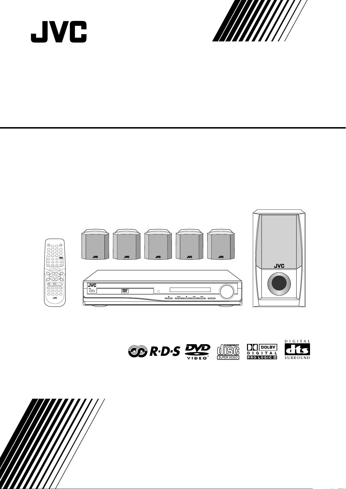
DVD DIGITAL CINEMA SYSTEM
SOUND
VOLUME
SOURCE
STANDBY
STANDBY/ON
DVD DIGITAL CINEMA SYSTEM TH-A25
TH-A25
Consists of XV-THA25 and SP-THA25
INSTRUCTIONS
LVT1111-003C
[B]
Page 2
Warnings, Cautions and Others
IMPORTANT for the U.K.
DO NOT cut off the mains plug from this equipment. If the plug
fitted is not suitable for the power points in your home or the
cable is too short to reach a power point, then obtain an
appropriate safety approved extension lead or consult your
dealer.
BE SURE to replace the fuse only with an identical approved
type, as originally fitted.
If nonetheless the mains plug is cut off ensure to remove the
fuse and dispose of the plug immediately, to avoid a possible
shock hazard by inadvertent connection to the mains supply.
If this product is not supplied fitted with a mains plug then follow
the instructions given below:
IMPORTANT.
DO NOT make any connection to the terminal which is marked
with the letter E or by the safety earth symbol or coloured green
or green-and-yellow.
The wires in the mains lead on this product are coloured in
accordance with the following code:
Blue : Neutral
Brown : Live
As these colours may not correspond with the coloured
markings identifying the terminals in your plug proceed as
follows:
The wire which is coloured blue must be connected to the
terminal which is marked with the letter N or coloured black.
The wire which is coloured brown must be connected to the
terminal which is marked with the letter L or coloured red.
IF IN DOUBT - CONSULT A COMPETENT ELECTRICIAN.
CAUTION
To reduce the risk of electrical shocks, fire, etc.:
1. Do not remove screws, covers or cabinet.
2. Do not expose this appliance to rain or moisture.
Caution ––STANDBY/ON switch!
Disconnect the mains plug to shut the power off completely.
The STANDBY/ON button in any position does not disconnect the mains line.
The power can be remote controlled.
CAUTION
• Do not block the ventilation openings or holes.
(If the ventilation openings or holes are blocked by a newspaper or cloth, etc., the heat may not be able to get out.)
• Do not place any naked flame sources, such as lighted
candles, on the apparatus.
• When discarding batteries, environmental problems must be
considered and local rules or laws governing the disposal of
these batteries must be followed strictly.
• Do not expose this apparatus to rain, moisture, dripping or
splashing and that no objects filled with liquids, such as vases,
shall be placed on the apparatus.
G-1
Page 3
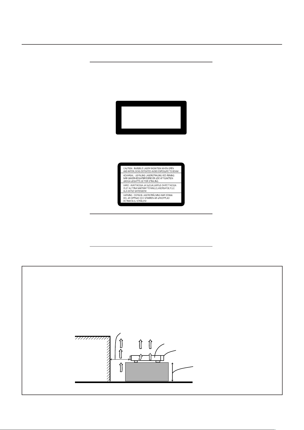
IMPORTANT FOR LASER PRODUCTS
CLASS 1 LASER PRODUCT
KLASSE 1 LASER PRODUKT
LUOKAN 1 LASER LAITE
KLASS 1 LASER APPARAT
PRODUCTO LASER CLASE 1
REPRODUCTION OF LABELS
1 CLASSIFICATION LABEL, PLACED ON EXTERIOR SURFACE
2 WARNING LABEL, PLACED INSIDE THE UNIT
1. CLASS 1 LASER PRODUCT
2. CAUTION: Invisible laser radiation when open and interlock
failed or defeated. Avoid direct exposure to beam.
3. CAUTION: Do not open the top cover. There are no user
serviceable parts inside the Unit; leave all servicing to
qualified service personnel.
Caution: Proper Ventilation
To avoid risk of electric shock and fire and to protect from damage.
Locate the apparatus as follows:
Front: No obstructions open spacing.
Sides: No obstructions in 10 cm from the sides.
Top: No obstructions in 10 cm from the top.
Back: No obstructions in 15 cm from the back
Bottom: No obstructions, place on the level surface.
In addition, maintain the best possible air circulation as illustrated.
Spacing 15 cm or more
Wall or obstructions
XV-THA25
Front
Stand height 15 cm or more
Floor
G-2
Page 4

SAFETY INSTRUCTIONS
“SOME DOS AND DON’TS ON THE SAFE USE OF EQUIPMENT”
This equipment has been designed and manufactured to meet international safety standards but, like any electrical equipment, care must be
taken if you are to obtain the best results and safety is to be assured.
Do read the operating instructions before you attempt to use the equipment.
Do ensure that all electrical connections (including the mains plug, extension leads and interconnections between pieces of equipment) are
properly made and in accordance with the manufacturer’s instructions. Switch off and withdraw the mains plug when making or changing
connections.
Do consult your dealer if you are ever in doubt about the installation, operation or safety of your equipment.
Do be careful with glass panels or doors on equipment.
DON’T continue to operate the equipment if you are in any doubt about it working normally, or if it is damaged in any way–switch off, withdraw
the mains plug and consult your dealer.
DON’T remove any fixed cover as this may expose dangerous voltages.
DON’T leave equipment switched on when it is unattended unless it is specifically stated that it is designed for unattended operation or has
a standby mode.
Switch off using the switch on the equipment and make sure that your family know how to do this.
Special arrangements may need to be made for infirm or handicapped people.
DON’T use equipment such as personal stereos or radios so that you are distracted from the requirements of traffic safety. It is illegal to watch
television whilst driving.
DON’T listen to headphones at high volume as such use can permanently damage your hearing.
DON’T obstruct the ventilation of the equipment, for example with curtains or soft furnishings.
Overheating will cause damage and shorten the life of the equipment.
DON’T use makeshift stands and NEVER fix legs with wood screws — to ensure complete safety always fit the manufacturer’s approved
stand or legs with the fixings provided according to the instructions.
DON’T allow electrical equipment to be exposed to rain or moisture.
ABOVE ALL
— NEVER let anyone, especially children, push anything into holes, slots or any other opening in the case -this could result in a fatal
electrical shock.;
— NEVER guess or take chances with electrical equipment of any kind — it is better to be safe than sorry!
G-3
Page 5

Table of Contents
Parts Identification ...................................... 2
Center Unit ................................................................................. 2
Remote Control .......................................................................... 3
Getting Started ........................................... 4
Before Installation ...................................................................... 4
Checking the Supplied Accessories ........................................... 4
Putting Batteries in the Remote Control .................................... 4
Connecting the FM and AM Antennas ....................................... 5
Speaker Layout Diagram ............................................................ 6
Connecting the Speakers ............................................................ 7
Connecting Audio/Video Component ........................................ 8
Basic Disc Operations ................................ 10
1 Turn On the Power ............................................................... 10
2 Select the Source .................................................................. 10
3 Load a Disc .......................................................................... 10
4 Start Playback ...................................................................... 11
5 Adjust the Volume ................................................................ 11
6 Activate Surround ................................................................ 11
Moving to Another Chapter/Track/File .................................... 12
Stopping Playback .................................................................... 12
Basic Tuner Operations .............................. 13
1 Turn On the Power ............................................................... 13
2 Select the Band .................................................................... 13
3 Adjust the Volume ................................................................ 13
4 Tune into a Station ............................................................... 13
Other Basic Operations .............................. 14
Enjoying Sounds from the External Component ..................... 14
Turning Off the Power with the Timer ..................................... 14
Adjusting the Display Brightness ............................................. 14
Creating Realistic Sound Fields ................... 15
Using the Test Tone .................................................................. 15
Adjusting the Sound ................................................................. 15
7 Basic sound adjustment procedure ....................................... 16
Surround Mode Introduction .................................................... 17
7 Dolby Digital and DTS Digital Surround ............................. 17
7 Dolby Pro Logic II modes .................................................... 17
Activating the Surround Mode ................................................. 18
Disc Introduction—DVD/VCD/SVCD/CD ...... 19
Disc Playback ............................................ 20
Using the On-Screen Bar ......................................................... 20
7 Showing the On-Screen Bar ................................................. 20
7 Basic operation through the On-Screen Bar ......................... 21
Selecting the Audio Languages ................................................ 22
Selecting the Subtitles .............................................................. 22
Selecting the Playback Channel ............................................... 23
Selecting the Multi-Angle Views ............................................. 23
Checking the Remaining Time ................................................. 23
Disc Menu-Driven Playback .................................................... 24
Moving to a Particular Portion Directly ................................... 25
Searching for a Particular Point ............................................... 25
Repeating Playback .................................................................. 26
7 Repeat Play ........................................................................... 26
7 A–B Repeat ........................................................................... 26
Special Picture Playback .......................................................... 27
7 Still Picture/Frame-by-Frame Playback ............................... 27
7 Slow Motion Playback ......................................................... 27
7 Zoom .................................................................................... 27
MP3/JPEG Introduction ............................ 28
MP3/JPEG Playback ................................. 29
Starting Playback ..................................................................... 29
Showing the On-Screen Bar ..................................................... 29
Operations Using the On-Screen Display ................................ 30
Selecting a Particular File/Folder Directly ............................... 31
Repeating Playback .................................................................. 31
Browsing Pictures in the Current Folder .................................. 31
Rotating and Flipping a Picture ................................................ 31
Tuner Operations ....................................... 32
Tuning in Stations .................................................................... 32
Using Preset Tuning ................................................................. 33
Selecting the FM Reception Mode ........................................... 33
Using the RDS (Radio Data System)
to Receive FM Stations ...................................................... 34
Searching for a Program by PTY Codes .................................. 35
Switching to a Selected Program ............................................. 35
7 Description of the PTY codes .............................................. 36
Setting Up the DVD Preferences ................. 37
Setting the System Preferences ................................................ 37
7 The basic procedure to set up the system preferences .......... 38
7 To adjust the DRC (Dynamic Range Compression) ............. 38
Setting the Preferences ............................................................. 39
7 The basic procedure to set up preferences ............................ 39
7 To set the parental (rating) level ........................................... 40
7 To change the password ........................................................ 40
7 To release the parental lock temporarily .............................. 41
7 Language Code List .............................................................. 41
Operating TV............................................. 42
Maintenance ............................................. 43
Troubleshooting ......................................... 44
Specifications............................................ 45
1
Page 6
Parts Identification
VOLUME
SOURCE
STANDBY
STANDBY/ON
DVD DIGITAL CINEMA SYSTEM TH-A25
2
6 7
98
4 5
3
1
RT
MHz
k
Hz
RDS
PRGM
CHAP TUNEDPBC
TITLE
LINEAR PCM
ST
L C R
SW
LS
S RS
1
wp
5 63 42 7 8 9
q
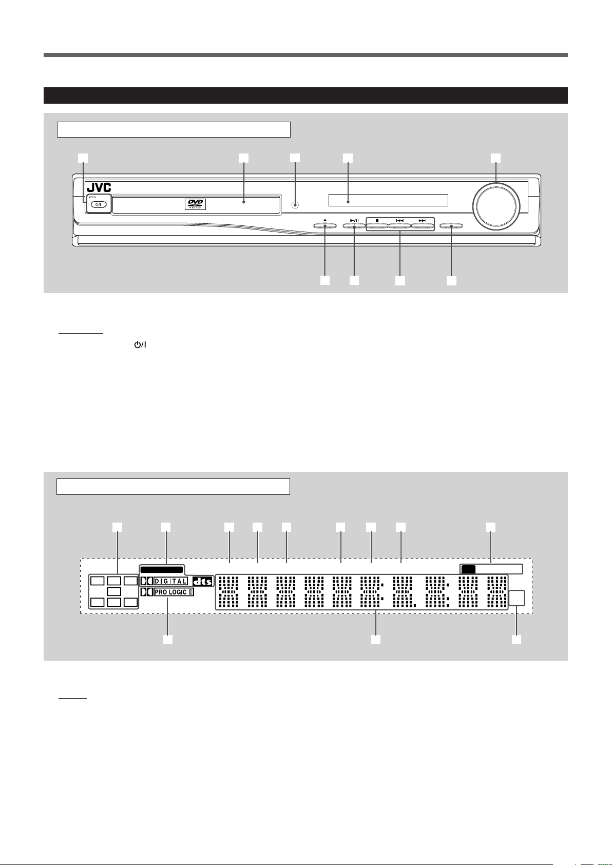
Center Unit
Front Panel
See pages in the parentheses for details.
Front Panel
1 STANDBY/ON button and STANDBY lamp (10–13)
2 Disc tray (10)
3 Remote sensor
4 Display
5 VOLUME control (11, 13)
6 0 (open/close) button (10, 12)
• Pressing this button also turns on the power and
changes the source to the DVD/CD.
7 3/8 (play/pause) button (11, 12, 29)
• Pressing this button also turns on the power and
changes the source to the DVD/CD.
8 Multi operation buttons
• 4, ¢, and 7
9 SOURCE button (10, 13, 14)
See pages in the parentheses for details.
Display
1 Audio channel indicators
• Indicates audio channels currently being reproduced.
2 Digital signal indicators (11, 17, 18)
• LINEAR PCM, DOLBY DIGITAL, and DTS.
3 TITLE indicator (11)
• Indicates the current title number with main display.
4 PBC (Play Back Control) indicator
• Goes on when the PBC function is activated.
5 CHAP (chapter) indicator (11)
• Indicates the current chapter number with main display.
Display
6 PRGM (program) indicator (33)
7 RDS indicator (34)
8 RT indicator (34)
9 Tuner mode indicators (13, 32, 33)
• ST (stereo) and TUNED
p Dolby PRO LOGIC II indicator (11, 17, 18)
q Main display
w Frequency unit indicators
• kHz (for AM band station) and MHz (for FM band
station)
2
Page 7
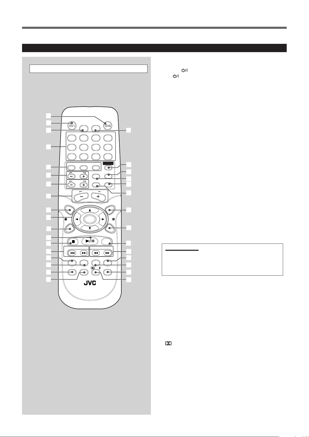
Remote Control
1
2
3
4
5
6
7
8
9
y
p
q
e
w
u
i
;
a
s
d
r
t
f
g
h
k
l
/
o
z
x
AUDIOTV
SLEEPDIMMER
DVD FM/AM
TV CH
AUX
TV/VIDEO
MUTING
CONTROL
TEST TONE
TOP
MENU
MENU
PTY
NEWS/INFO
PTY SEARCH
CHOICE/TIME
DOWN - TUNING - UP
AUDIO
SLOW RETURN PL
RDS
RM-STHA25R
DVD CINEMA SYSTEM
REPEAT
SUBTITLE ANGLE ZOOM
ON SCREEN
TV VOL
AUDIO VOL
1234
5678
9
TV
0
MEMORY
CANCEL
ENTER
SOUND
STEP
FM MODE
PTY
j
See pages in the parentheses for details.
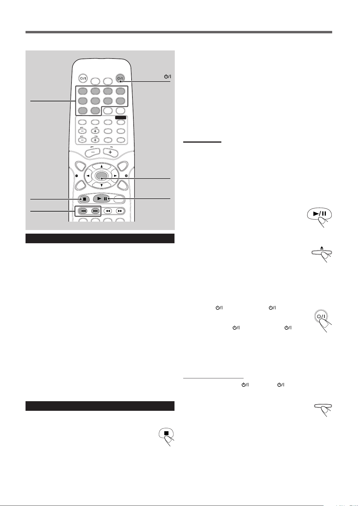
Remote Control
1 AUDIO
2 TV
button (10, 12, 13)
button (10, 42)
3 DIMMER button (14)
4 • Number buttons
• MEMORY button (33)
• CANCEL button
5 Source selecting buttons
• DVD, FM/AM, AUX (10, 13, 14)
• Pressing one of these buttons also turns on the power.
6 TV CH + and – buttons (42)
7 TV VOL + and – buttons (42)
8 AUDIO VOL + and – buttons (11, 13)
9 TOP MENU button (24)
p • 3, 2, 5, and ∞ buttons
• ENTER button
• NEWS/INFO button (35)
• PTY 9 and ( buttons (35)
• PTY SEARCH button (35)
q CHOICE/TIME button (23, 29, 38–40)
w 3/8 button
e 7 button
r 4 and ¢ buttons
t AUDIO button (22, 23)
y SUBTITLE button (22)
u • SLOW button (27)
• RDS button (34)
i RETURN button (24)
o SLEEP button (14)
; SOUND button (16)
a TEST TONE button (15)
s CONTROL TV button (42)
IMPORTANT:
When you press CONTROL TV, some buttons on the remote control
cannot work for operating the center unit. To operate the center
unit, press DVD, FM/AM, or AUX depending on your target
operation.
d MUTING button (11)
f TV/VIDEO button (10, 42)
g MENU button (24, 31)
h ON SCREEN button (20–26, 29)
j STEP button (27)
k • 1 and ¡ buttons
• TUNING UP and DOWN buttons (13, 32)
l ZOOM button (27)
/ ANGLE button (23)
z • REPEAT button (26, 31)
• FM MODE button (33)
x
PL II button (11, 18)
3
Page 8
Getting Started
Before Installation
General Precautions
• DO NOT insert any metal object into the center unit.
• DO NOT disassemble the center unit or remove screws, covers, or
cabinet.
• DO NOT expose the center unit to rain or moisture.
Locations
• Install the center unit in a location that is level and protected from
moisture.
• The temperature around the center unit must be between 5˚C and
35˚C.
• Make sure there is good ventilation around the center unit. Poor
ventilation could cause overheating and damage the center unit.
Handling the center unit
• DO NOT touch the power cord with wet hands.
• DO NOT pull on the power cord to unplug the cord. When
unplugging the cord, always grasp the plug so as not to damage
the cord.
• Keep the power cord away from the connecting cords and the
antenna. The power cord may cause noise or screen interference. It
is recommended to use a coaxial cable for antenna connection,
since it is well-shielded against interference.
• When a power failure occurs, or when you unplug the power cord,
the preset settings such as preset FM/AM channels and sound
adjustments may be erased in a few days.
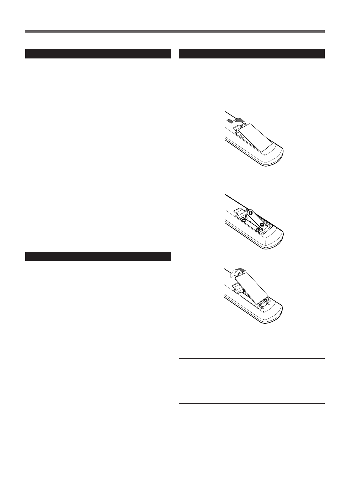
Putting Batteries in the Remote Control
Before using the remote control, put two supplied batteries first.
• When using the remote control, aim the remote control directly at
the remote sensor on the center unit.
1. On the back of the remote control, remove the
battery cover.
2. Insert batteries. Make sure to match the polarity:
(+) to (+) and (–) to (–).
Checking the Supplied Accessories
Check to be sure you have all of the following supplied accessories.
The number in the parentheses indicates the quantity of the pieces
supplied.
• Remote Control (1)
• Batteries (2)
• AM Loop Antenna (1)
• FM Antenna (1)
• Video Cord (1)
• Speaker Cords
6 m (4): For subwoofer
For the satellite speakers on the following positions:
left front, right front, and center
10 m (2): For the satellite speakers on left and right rear
positions
If anything is missing, contact your dealer immediately.
3. Replace the cover.
If the range or effectiveness of the remote control decreases, replace
the batteries. Use two R6P(SUM-3)/AA(15F) type dry-cell batteries.
CAUTION:
Follow these precautions to avoid leaking or cracking cells:
• Place batteries in the remote control so they match the polarity: (+)
to (+) and (–) to (–).
• Use the correct type of batteries. Batteries that look similar may
differ in voltage.
• Always replace both batteries at the same time.
• Do not expose batteries to heat or flame.
4
Page 9
COMPOSITE
RGB
L
R
CENTER
WOOFERFRONT
L
R
REAR
AUDIO IN
DIGITAL IN
OPTICAL
AUX
IMPEDANCE
WOOFER:MIN 3
FRONT/CENTER
MIN 6
REAR
MIN 6
1
2
3
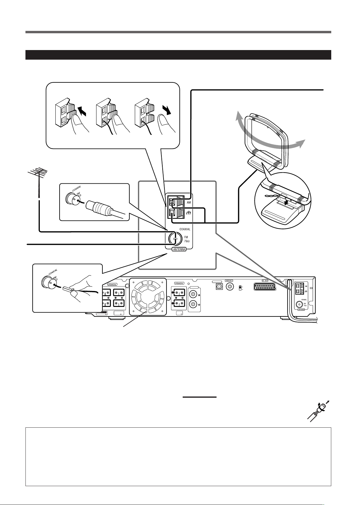
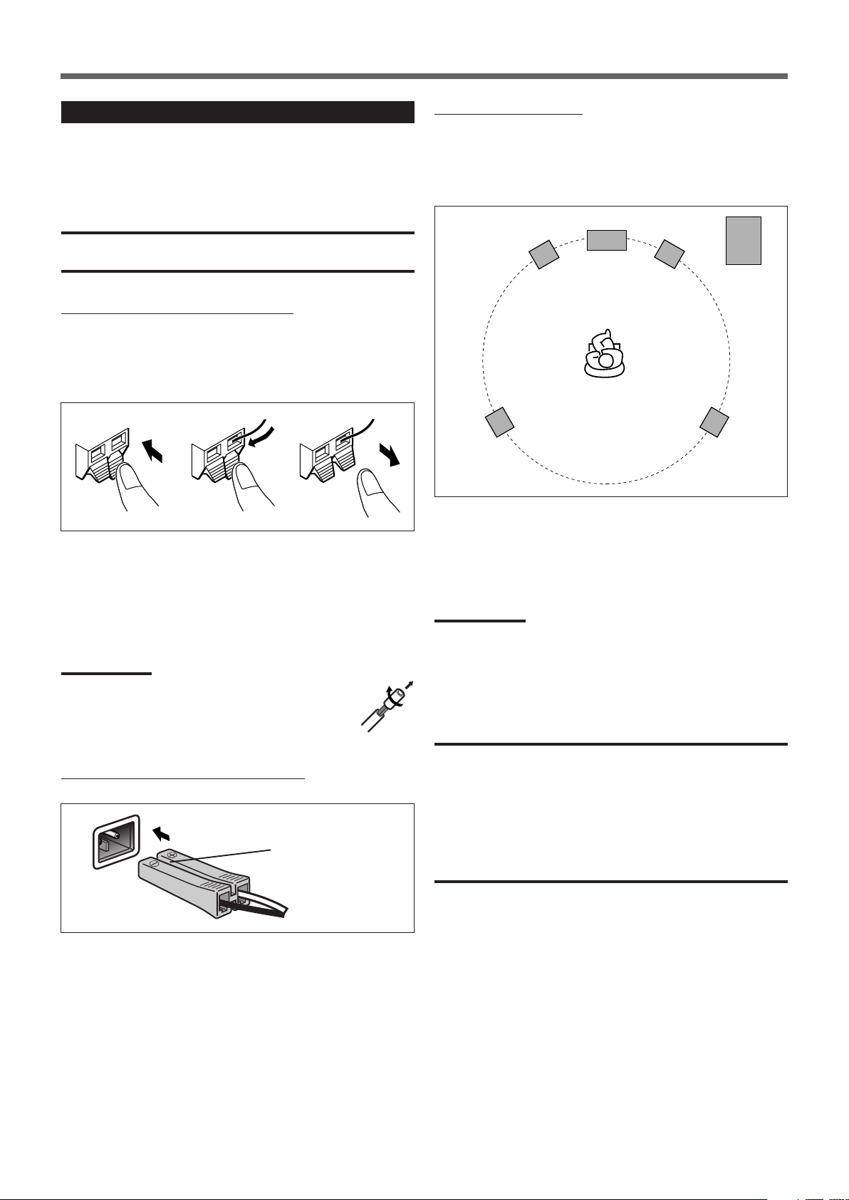
Connecting the FM and AM Antennas
If FM reception is poor, connect
outdoor FM antenna (not supplied).
If AM reception is poor, connect single vinyl-covered
wire (not supplied).
AM Loop antenna
(supplied)
FM antenna (supplied)
Cooling fan
(See “About the cooling fan” below.)
FM antenna connection
Connect the supplied FM antenna to the COAXIAL FM 75 Ω
terminal as temporary measure.
Extend the supplied FM antenna horizontally.
• If reception is poor, connect an outdoor antenna. Before attaching
a 75 Ω coaxial cable (with a standard type connector), disconnect
the supplied FM antenna.
Snap the tabs on the loop into
the slots of the base to
assemble the AM Loop
antenna.
Center unit
AM antenna connection
Connect the supplied AM Loop antenna to the AM and H terminals.
Turn the loop until you have the best reception.
• If reception is poor, connect an outdoor single vinyl-covered wire
to the AM terminal. (Keep the AM Loop antenna connected.)
Notes:
If the AM Loop antenna wire is covered with vinyl, remove
the vinyl by twisting it as shown in the diagram.
About the cooling fan
A cooling fan is mounted on the rear panel of the center unit to
prevent abnormal temperature inside the center unit, thus assuring
normal operation of the unit. The cooling fan automatically starts
rotating to intake external cool air when the internal temperature
goes up.
For safety, observe the following carefully.
• Make sure there is good ventilation around the center unit. Poor
ventilation could overheat and damage the center unit.
• DO NOT block the cooling fan and the ventilation openings or
holes. (If they are blocked by a newspaper or cloth, etc., the
heat may not be able to get out.)
• DO NOT touch the speaker cords to the cooling fan.
5
Page 10
Getting Started
Subwoofer
(WOOFER)
Left rear
position
Right front
position
Right rear
position
To the speaker
on left front
(White connector)
To subwoofer (WOOFER)
(Purple connector)
Left front
position
Center unit
Center position
VOLUME
SOURCE
STANDBY
STANDBY/ON
DVD DIGITAL CINEMA SYSTEM TH-A25
VOLUME
SOURCE
STANDBY
STANDBY/ON
DVD DIGITAL CINEMA SYSTEM TH-A25
L
R
CENTER
WOOFERFRONT
L
R
REAR
AUDIO IN
AUX
L
R
CENTER
WOOFERFRONT
L
R
REAR
AUDIO IN
AUX
L
R
CENTER
WOOFERFRONT
L
R
REAR
AUDIO IN
AUX
L
R
CENTER
WOOFERFRONT
L
R
REAR
AUDIO IN
AUX
To the speaker
on right front
(Red connector)
To the speaker on left rear
(Blue connector)
IMPEDANCE
WOOFER:MIN 3
FRONT/CENTER
MIN 6
REAR
MIN 6
To the speaker on center
(Green connector)
To the speaker on right rear
(Gray connector)
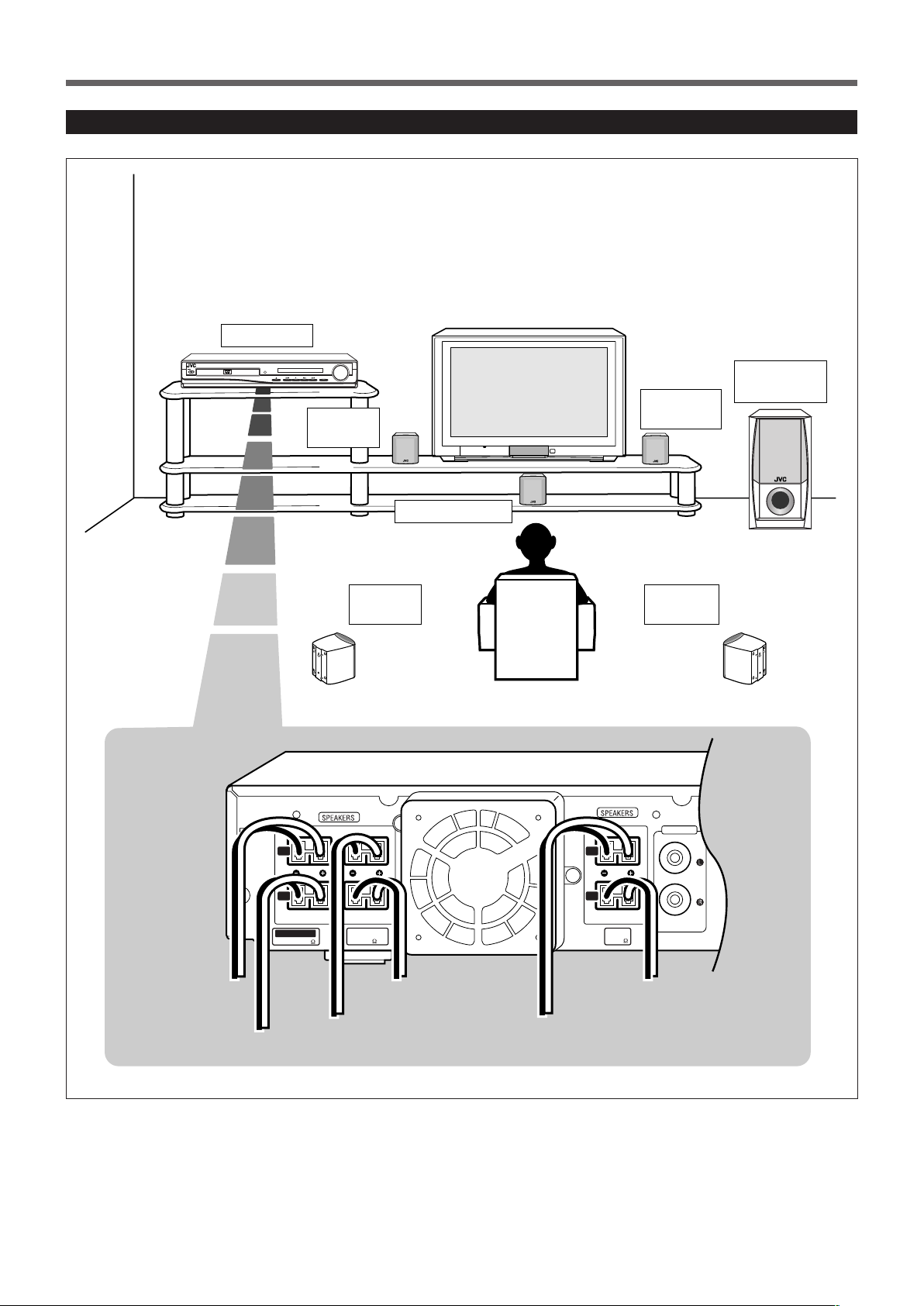
Speaker Layout Diagram
6
Page 11
Connecting the Speakers
Left front
speaker
Right front
speaker
Right rear
speaker
Subwoofer
Left rear
speaker
Center speaker
132
Connect the satellite speakers and subwoofer to the terminals on the
rear panel using speaker cords supplied.
The ends of the speaker cords are colored to indicate the terminals to
be connected.
CAUTION:
Use speakers with the SPEAKER IMPEDANCE indicated by the
speaker terminals.
Connecting speaker cords to the speakers
• Connect the cord with a gray tube to the red (+) terminal, and the
cord with a black tube to the black (–) terminal respectively.
• You can use the satellite speakers interchangeably for any position
except for subwoofer. Make sure not to connect the subwoofer
terminal and the satellite speaker.
1
Press and hold the terminal clamp.
2
Insert the speaker cord.
When setting the speakers
To obtain the best possible sound from this system, you need to
place all the speakers except the subwoofer at the same distance
from the listening position with each front faced toward the listener.
Since bass sound is non-directional, you can place a subwoofer
wherever you like. Normally place it in front of you.
If your speakers cannot be placed at the same distance from the
listening position
You can adjust the delay time of the center speaker and rear
speakers. For in-depth information about adjusting the delay time,
see “Adjusting the Sound” on page 15.
3
Release the finger from the clamp.
Notes:
• If the speaker cord is covered with vinyl, remove the vinyl
by twisting it as shown in the diagram.
• Make sure the core wire of speaker cords do not expose
to out of the terminals. This could cause
short-circuit.
Connecting speaker cords to the center unit
With the Side marked ª and
· upward.
Speaker Connector
Insert the speaker connectors to the speaker
terminals on the rear panel.
• Make sure to match the color of the connector and the terminal.
Notes:
You can change the phase of subwoofer sounds by connecting the
speaker cords to the terminals inversely—the cord with a gray tube to
the black terminal, and the cord with a black tube to the red terminal.
You may get more effective bass sounds by changing the phase.
CAUTIONS:
• When attaching the satellite speakers on the wall, have them
attached to the wall by a qualified person.
DO NOT attach the satellite speakers on the wall by yourself to
avoid an unexpected damage of their falling from the wall, caused
by incorrect attachment or weakness in the wall.
• Care is required in selecting a location for attaching speakers to the
wall. Injury to personnel, or damage to equipment, may result if the
speakers are attached in a location which interferes with daily
activities.
7
Page 12
Getting Started
COMPOSITE
RGB
COMPOSITE
RGB
A
B
COMPOSITE
RGB
L
R
REAR
AUDIO IN
DIGITAL IN
OPTICAL
AUX
1
REAR
MIN 6
TV
A
COMPOSITE
RGB
B
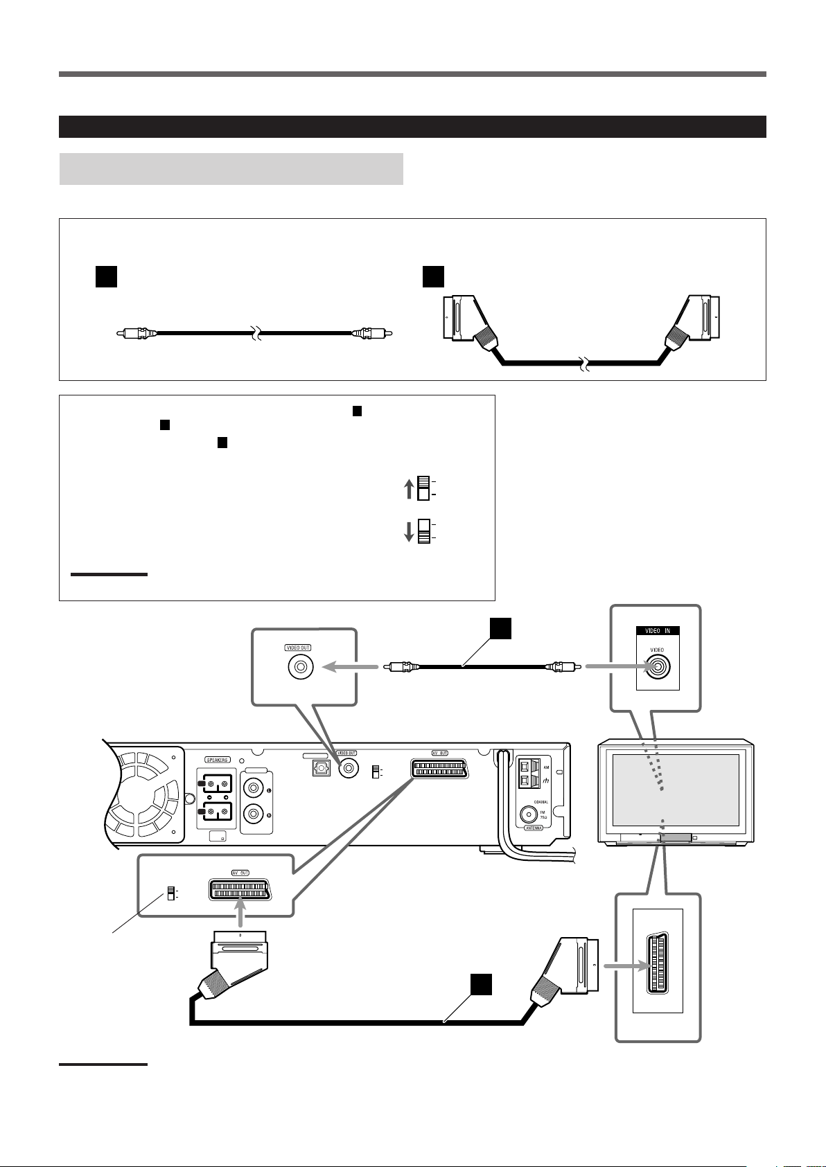
Connecting Audio/Video Component
Turn the power off to all components before connections.
TV connection
The SCART cable is not supplied with this system.
Use the cable supplied with the other component or purchase one at an electric appliance store.
Video cord (supplied) SCART cable (not supplied)
You can connect TV with either the composite video cord (A) or
the SCART cable (B).
For using the SCART cable (B)
Turn off the power of the system and your TV before setting RGB/
COMPOSITE selector.
• If RGB input is equipped for your TV, set RGB/COMPOSITE
selector on the rear panel to “RGB.” You can get a better picture
quality by using RGB out setting.
• If RGB input is not equipped for your TV, set RGB/COMPOSITE
selector to “COMPOSITE.”
Notes:
The AV OUT on this unit is not compatible with the S-VIDEO signal.
RGB/COMPOSITE
selector
Notes:
The SCART terminal on the rear panel is indicated as “AV OUT.” However, this terminal is designed as video output. So, no audio signals are
emitted through this terminal.
8
Page 13
A
B
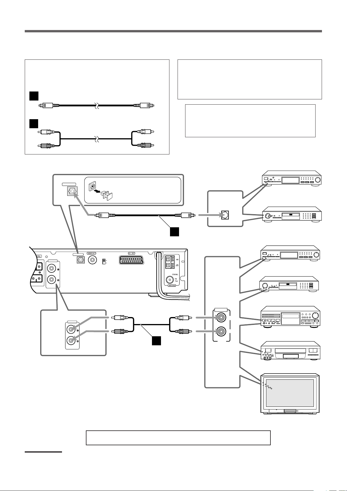
Audio component connection
COMPOSITE
RGB
L
R
REAR
AUDIO IN
DIGITAL IN
OPTICAL
AUX
DBS Tuner
Center unit
MD Recorder
Cassette Deck
OUT
LEFT
RIGHT
AUDIO
VCR
TV
MD Recorder
DIGITAL
OPTICAL OUT
A
B
DBS Tuner
AUDIO IN
AUX
DIGITAL IN
OPTICAL
Connect other components to the center unit with the audio
cord.
Use the cord supplied with the other component or purchase
one at an electric appliance store.
Optical digital cord (not supplied)
Audio cord (not supplied)
Before connecting an optical
digital cord, unplug the
protective plug.
Illustrations of the input/output terminals below are typical
examples.
When you connect other components, refer also to their
manuals since the terminal name actually printed on the rear
vary among the components.
If you connect a sound-enhancing device such as a
graphic equalizer between the source component and
the center unit, the sound output through this system
may be distorted.
Notes:
Now, you can plug the power cord of the center unit into the AC outlet.
• Keep the power cord away from the connecting cords and the antenna. The power cord may cause noise or screen interference.
• Connecting to a TV through a VCR, or to a TV with a built-in VCR, may cause distortion of picture.
9
Page 14
AUDIOTV
SLEEPDIMMER
DVD FM/AM
TV CH
AUX
TV/VIDEO
MUTING
CONTROL
TEST TONE
TOP
MENU
MENU
PTY
NEWS/INFO
PTY SEARCH
CHOICE/TIME
AUDIO
SLOW RETURN PL
RDS
RM-STHA25R
DVD CINEMA SYSTEM
SUBTITLE ANGLE ZOOM
ON SCREEN
TV VOL
AUDIO VOL
1234
5678
9
TV
0
MEMORY
CANCEL
ENTER
SOUND
/
REPEAT
FM MODE
STEP
PTY
DOWN - TUNING - UP
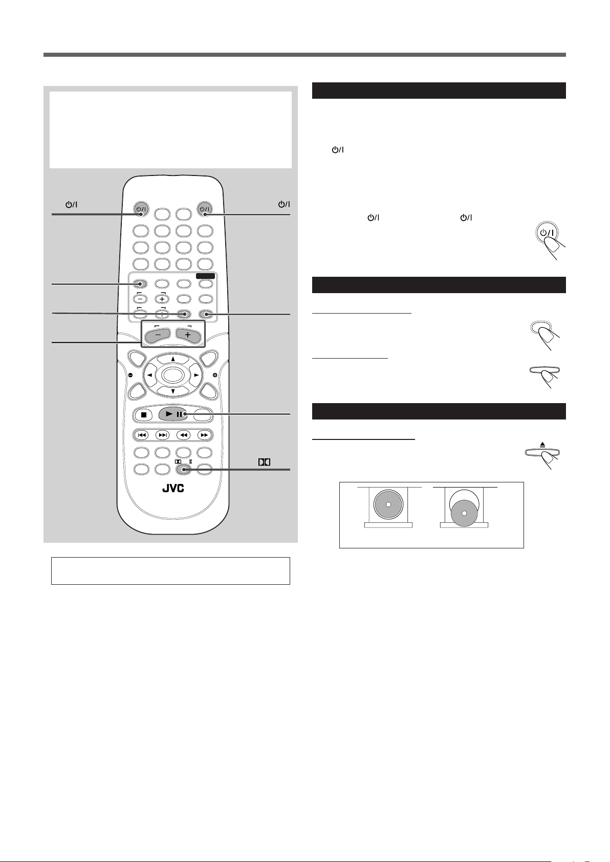
Basic Disc Operations
DVD
SOURCE
AUDIO
This manual mainly explains operations using the buttons on
the remote control. You can also use the buttons on the center
unit if they have the similar names (or marks) as those on the
remote control.
If operations using the center unit are different from those
using the remote control, they are then explained.
1
TV
2
DVD
AUDIO
1
Turn On the Power
Before turning on the system, turn on your TV and select the correct
video input. (See the manual supplied with your TV.)
• When you use a JVC’s TV, you can turn on your TV by pressing
on the remote control, and select the video input by
TV
pressing TV/VIDEO.
• For changing the OSD messages—the information on the TV
screen—into the desired language, see “Setting the System
Preferences” on page 37.
Press AUDIO
(or STANDBY/ON on the front
panel).
The STANDBY lamp goes off.
The source indication selected previously appears on the
display.
2
Select the Source
TV/VIDEO
5
AUDIO VOL
+/–
For in-depth information about disc operations, see
pages 20 to 31.
MUTING
4
6
3/8
PL II
From the remote control:
Press DVD.
The source changes to the DVD/CD player.
On the front panel:
Press SOURCE repeatedly until “DVD/CD” appears
on the display.
3
Load a Disc
On the front panel ONLY:
Press 0 to open the disc tray, then place a disc
correctly with its label side up (for double-sided DVD,
the side you want to playback up).
CORRECT INCORRECT
• When using an 8 cm disc, place it on the inner circle of the disc
tray.
• Continued use of irregular shape discs (heart-shape, octagonal,
etc.) can damage the center unit.
• DO NOT use the disc stabilizer.
10
Page 15
4
AUDIO VOL
MUTING
PL
PLII MUSIC PLII MOVIE
STEREO
(PL II OFF)
PRO LOGIC
PLII MATRIX
VOLUME
CHAP
TITLE
L C R
SW
LS
RS
LINEAR PCM
L R
SW
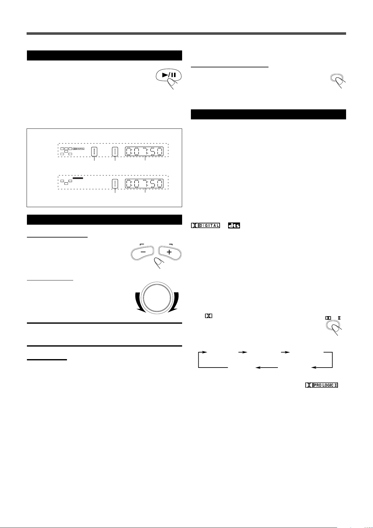
Start Playback
Press 3/8.
The disc tray closes. “LOADING” appears on the
display for a while.
• You can also start playback by closing the disc tray
using 0 on the front panel.
• Some discs show menus on the TV screen after you press 3/8.
See “Disc Menu-Driven Playback” on page 24 and refer to the
instructions supplied for the discs to use the menus.
Playback Information on the display
DVD
Title No. Chapter No. Elapsed playing
time
CD/VCD
To turn off the sounds temporarily
From the remote control ONLY:
Press MUTING.
To restore the sound, press MUTING again.
• Adjusting the volume also restores the sound.
6
Activate Surround
You can enjoy two kinds of surround—Digital Multichannel
Surround (Dolby Digital and DTS Digital Surround) and Dolby Pro
Logic II.
Digital Multichannel Surround—Dolby Digital
and DTS Digital Surround
Dolby Digital or DTS Digital Surround takes effect only when you
play back a disc encoded with these signals.
5
Adjust the Volume
Track No. Elapsed playing
time
From the remote control:
To increase the volume,
press and hold AUDIO VOL +.
To decrease the volume,
press and hold AUDIO VOL –.
On the front panel:
To increase the volume,
turn VOLUME control clockwise.
To decrease the volume,
turn VOLUME control counterclockwise.
CAUTION:
Always set the volume to the minimum before starting any source. If
the volume is set at its high level, the sudden blast of sound energy
can permanently damage your hearing and/or ruin your speakers.
Notes:
• By pressing AUDIO VOL + or – repeatedly, you can adjust the
volume level step by step.
• The volume level can be adjusted within 51 steps—
“MIN (minimum),” “1” to “49,” and “MAX (maximum).”
• If you have turned off the unit with the volume level set at more than
level “25,” the volume level will be automatically set at level “25” next
time you turn on the unit.
To activate Dolby Digital or DTS Digital Surround
When a Dolby Digital or DTS multi-channel disc is loaded, the
system detects it and starts playing the disc automatically with
Multichannel Surround activated.
or indicator lights up on the display according to
the signal detected.
– For in-depth information about Multichannel Surround, see
“Surround Mode Introduction” on page 17.
Dolby Pro Logic II modes—Pro Logic II Music,
Pro Logic II Movie, Matrix, and Pro Logic
To activate Pro Logic II modes
You can use these modes when playing back any 2-channel sources
either digital or analog.
Press
The current Pro Logic II mode appears on the display for
a while.
• Each time you press the button, Pro Logic II mode
• When Dolby Pro Logic II mode is activated, the
– For in-depth information about Dolby Pro Logic II modes, see
PL II.
changes as follows:
indicator lights up on the display.
“Surround Mode Introduction” on page 17.
11
Page 16
DOWN - TUNING - UP
AUDIO
SOURCE
Basic Disc Operations
AUDIOTV
SLEEPDIMMER
Number buttons
7
1234
5678
9
DVD FM/AM
TV CH
TV VOL
TOP
MENU
PTY
CHOICE/TIME
MEMORY
0
AUX
CONTROL
TV
TV/VIDEO
AUDIO VOL
NEWS/INFO
ENTER
PTY SEARCH
/
CANCEL
SOUND
TEST TONE
MUTING
MENU
PTY
ON SCREEN
STEP
¢/4
AUDIO SUBTITLE ANGLE ZOOM
Moving to Another Chapter/Track/File
To go to another chapter (for DVD), track (for
CD and VCD), or file (for MP3 and JPEG)
Press ¢ or 4 repeatedly during playback.
• ¢: Skips to the beginning of the next or succeeding chapter,
track, or file.
• 4: Goes back to the beginning of the current or previous
chapter, track, or file.
• You can skip some 5 minutes forward/back with pressing ¢/
4 while you are playing back a VCD track which is longer than
some 15 minutes.
To go to another track (only possible on a CD
and VCD without PBC) directly using the
number buttons
Pressing the number buttons before or during play allows you to start
playing the track number you want. If your TV is turned on, “SELECT
XX” (XX is the selected track number) appears on the TV screen.
• To select number 1 to 9, press the corresponding number button,
then press ENTER.
• To select number 15, press 1, 5, then press ENTER.
• To select number 23, press 2, 3, then press ENTER.
Stopping Playback
To stop playback
Press 7.
Playback stops.
AUDIO
ENTER
3/8
• This system can memorize the end point even when you press 7
once when playing back a DVD (“PRESS PLAY TO
CONTINUE” appears on the TV screen). When you start playback
again by pressing 3/8, playback begins from where it has been
stopped—Resume play.
Press 7 again, then press 3/8 to play back the DVD from the
beginning.
• When you start playback an MP3 or a JPEG file again by pressing
3/8, playback begins from the beginning of the file which had
been played before you stopped playback.
– For in-depth information about MP3/JPEG playback, see “MP3/
JPEG Playback” on pages 29–31.
Notes:
• The TV screen gets dark to save the screen when you leave the
system for a few minutes without any operations after stopping
playback. Press some button to restore the screen brightness.
• When the source is “DVD/CD,” the center unit turns off automatically
to save electrical consumption in the following cases:
–No playback starts for more than 20 minutes.
–“NO DISC” is shown on the display for more than 20 minutes.
Turn on the power again to use the system.
To stop playback for a moment
Press 3/8.
While pausing, the elapsed playing time flashes on the
display.
• To resume play, press 3/8 again.
To remove the disc
Press 0.
“OPEN” appears on the display and the disc tray comes out.
To close the disc tray, press 0 again.
• If you do not press the button, the disc tray closes automatically in
a few minutes.
To turn off the power (into standby)
Press AUDIO (or STANDBY/ON on the front
panel).
The STANDBY lamp lights up.
• If you press AUDIO
(or STANDBY/ON on the
front panel) while the disc tray is kept open, the disc tray
closes automatically, then the system is turned off.
• A small amount of power is consumed even in standby mode. To
turn the power off completely, unplug the AC power cord.
To prohibit disc ejection
On the front panel ONLY:
1 Press STANDBY/ON
control) to turn off the power.
The STANDBY lamp lights up.
2 Press and hold SOURCE for more than 5 seconds.
“LOCKED” appears on the display for a moment and
the disc tray is locked.
To unlock the disc tray, turn off the power, then press and hold
SOURCE for more than 5 seconds.
“UNLOCKED” appears on the display for a moment and the disc
tray is unlocked.
(or AUDIO on the remote
• You can neither lock nor unlock the disc tray while the system is
turned on.
12
Page 17

AUDIOTV
SLEEPDIMMER
DVD FM/AM
TV CH
AUX
TV/VIDEO
MUTING
CONTROL
TEST TONE
TOP
MENU
MENU
PTY
NEWS/INFO
PTY SEARCH
CHOICE/TIME
AUDIO
SLOW RETURN PL
RDS
RM-STHA25R
DVD CINEMA SYSTEM
SUBTITLE ANGLE ZOOM
ON SCREEN
TV VOL
AUDIO VOL
1234
5678
9
TV
0
MEMORY
CANCEL
ENTER
SOUND
/
REPEAT
FM MODE
STEP
PTY
DOWN - TUNING - UP
Basic Tuner Operations
AUDIO
FM/AM
SOURCE
AUDIO
DVD/CD DIGITAL IN
FMAM
AUX
AUDIO VOL
VOLUME
DOWN - TUNING - UP
1
AUDIO
2
FM/AM
On the front panel:
Press SOURCE repeatedly until the desired band (FM
or AM) appears on the display.
The last received station of the selected band is tuned into.
• Each time you press the button, the source changes as follows:
3
Adjust the Volume
3
AUDIO VOL
+/–
4
TUNING
UP/DOWN
For in-depth information about tuner operations, see
“Tuner Operations” on pages 32 to 36.
1
Turn On the Power
Press AUDIO (or STANDBY/ON on the front
panel).
The STANDBY lamp goes off.
The source indication selected previously appears on the
display.
2
From the remote control:
Press FM/AM.
The last received station of the selected band is tuned in.
• Each time you press the button, the band alternates between
FM and AM.
Select the Band
From the remote control:
To increase the volume,
press and hold AUDIO VOL +.
To decrease the volume,
press and hold AUDIO VOL –.
On the front panel:
To increase the volume,
turn VOLUME control clockwise.
To decrease the volume,
turn VOLUME control counterclockwise.
4
Tune into a Station
From the remote control:
Press and hold TUNING UP or DOWN until the
station frequency starts changing continuously on
the display.
The system starts searching for a station.
• When a station of sufficient signal strength is tuned in, the system
stops searching, and the
indicator lights up on the display.
On the front panel:
1 Press 7 so that “MANUAL” appears on the display.
2 Press and hold ¢ or 4 until the station frequency starts
changing continuously on the display.
The system starts searching for a station.
Notes:
• When an FM stereo program is received, the indicator also
lights up.
• When you press the button repeatedly, the frequency changes step
by step.
To turn off the power (into standby)
Press AUDIO (or STANDBY/ON on the front
panel).
The STANDBY lamp lights up.
• A small amount of power is consumed even in standby
mode. To turn the power off completely, unplug the AC
power cord.
13
Page 18

AUDIOTV
SLEEPDIMMER
DVD FM/AM
TV CH
AUX
TV/VIDEO
MUTING
CONTROL
TEST TONE
TOP
MENU
MENU
PTY
NEWS/INFO
PTY SEARCH
CHOICE/TIME
DOWN - TUNING - UP
AUDIO
SLOW RETURN PL
RDS
RM-STHA25R
DVD CINEMA SYSTEM
SUBTITLE ANGLE ZOOM
ON SCREEN
TV VOL
AUDIO VOL
1234
5678
9
TV
0
MEMORY
CANCEL
ENTER
SOUND
/
REPEAT
FM MODE
STEP
PTY
Other Basic Operations
10 20 30 60
150 120 90
OFF
(Canceled)
Dim
Dimmer
Canceled
(Normal Display)
AUX
SOURCE
SLEEP
SLEEP
SLEEP
DIMMER
AUX
DIGITAL IN
DVD/CD DIGITAL IN
FMAM
AUX
DIMMER
AUX
SLEEP
2
Start playback on the external component.
• For in-depth information about the external component, see
the manual supplied with it.
Notes:
• When “DIGITAL IN” is selected as the source and the Dolby Digital
or DTS multi-channel signal is detected, Multichannel Surround is
activated automatically.
For in-depth information about Multichannel Surround, see
“Surround Mode Introduction” on page 17.
• You can enjoy Dolby Pro Logic II mode when you playback any 2-
channel sources, either digital or analog.
For in-depth information about Dolby Pro Logic II modes, see
“Surround Mode Introduction” on page 17.
Turning Off the Power with the Timer
You can fall asleep while listening to music—Sleep Timer.
From the remote control ONLY:
Press SLEEP.
“SLEEP” and the shut-off time appear on the display.
• Each time you press the button, the shut-off time changes as
follows:
Enjoying Sounds from the External
Component
You can enjoy sounds from the external components connected to
the AUDIO IN jacks and the DIGITAL IN terminal on the rear panel
of the center unit.
1
Select AUX or DIGITAL IN as the source.
From the remote control:
Press AUX.
• Each time you press the button, the source changes as
follows:
On the front panel:
Press SOURCE repeatedly until “DIGITAL IN” or
“AUX” appears on the display.
When the shut-off time comes, the system turns off automatically.
To check or change the time remaining until the
shut-off time
Press SLEEP once.
The remaining time (in minutes) appears on the display.
• By pressing SLEEP, you can change the shut-off time.
To cancel the Sleep Timer
Press SLEEP repeatedly until “OFF” appears on the
display.
• Turning off the power also cancels the Sleep Timer.
Adjusting the Display Brightness
You can dim the display.
From the remote control ONLY:
Press DIMMER.
• Each time you press the button, the brightness level of the
display changes as follows:
DIGITAL IN: select this to enjoy the external component
AUX: select this to enjoy the external component
14
connected to DIGITAL IN terminal.
connected to AUDIO IN jacks.
Page 19

AUDIOTV
SLEEPDIMMER
DVD FM/AM
TV CH
AUX
TV/VIDEO
MUTING
CONTROL
TEST TONE
TOP
MENU
MENU
PTY
NEWS/INFO
PTY SEARCH
CHOICE/TIME
AUDIO
SLOW RETURN PL
RDS
RM-STHA25R
DVD CINEMA SYSTEM
SUBTITLE ANGLE ZOOM
ON SCREEN
TV VOL
AUDIO VOL
CENTER
TREBLE
L-F.BLANCE-R
SUBWOOFER
REAR
BASS
1234
5678
9
TV
0
MEMORY
CANCEL
ENTER
SOUND
/
PTY
REPEAT
FM MODE
STEP
DOWN - TUNING - UP
Creating Realistic Sound Fields
TEST TONE
Left front speaker
Right front speaker
Left rear speaker Right rear speaker
Center speaker
Subwoofer
L C R
SW
LS
RS
ENTER
■ To adjust speaker output level
You can adjust the output level of the center speaker, rear speakers,
and subwoofer listening to the test tone.
Press 3/2 while the test tone comes out of the
speaker you want to adjust.
The speaker output level appears on the display.
3: Increases the output level (to +06 dB).
2: Decreases the output level (to –06 dB).
TEST TONE
SOUND
3/2
To stop the test tone, press TEST TONE again.
Notes:
• You cannot use this function while playing back a disc. Stop the disc
playback to use this function when the source is DVD/CD.
• If no sounds come out of a speaker, check the speaker’s
connection (see pages 6 and 7).
• You cannot adjust the output level of rear speakers separately. See
“Adjusting the Sound” below to adjust the balance of rear speakers.
Adjusting the Sound
You can adjust the sound balance and the tone.
It is recommended to turn on your TV and make adjustments from
your actual listening point.
Using the Test Tone
You can check whether each speaker is connected properly.
From the remote control ONLY:
1
Press PL II repeatedly to activate all the
speakers.
The audio channel indicators light up on the display as follows
when all the speakers are activated:
• You can also activate all the speakers by loading a digital
2
Press TEST TONE.
The test tone comes out of the speakers in the following
order:
multichannel disc.
PL II
You can adjust the following settings:
Balance
FRONT BALANCE: To adjust the output balance for the front
speakers (from –00 to –06, OFF).
REAR BALANCE: To adjust the output balance for the rear
speakers (from –00 to –06, OFF).
CEN LEVEL: To adjust the output level of the center
Output level Tone
speaker (from –06 dB to +06 dB).
REAR LEVEL: To adjust the output level of the rear
speakers (from –06 dB to +06 dB).
S/W LEVEL: To adjust the output level of the
subwoofer (from –06 dB to +06 dB).
BASS: To adjust the output level of the bass
tone (from –10 dB to +10 dB, with 2 dB
step).
TREBLE: To adjust the output level of the treble
tone (from –10 dB to +10 dB, with 2 dB
step).
C-DLY: To adjust delay time for the center
Delay
speaker when the digital multichannel
surround is activated (from 0 msec to 5
msec).
R-DLY: To adjust delay time of the rear speakers
for each surround mode.
Notes:
You can also adjust the output level (CEN LEVEL, REAR LEVEL, and
S/W LEVEL) while using the test tone. See “Using the Test Tone” on
the left column.
15
Page 20

Creating Realistic Sound Fields
SOUND
L C R
SW
LS
RS
ENTER
C-DLY
*1*
2
R-DLY
*1*
3
REAR BALANCE
CEN LEVEL 0dB
REAR LEVEL 0dB
BASS 00dB
S/W (subwoofer) LEVEL 0dB
TREBLE 00dB
FRONT BALANCE
LR
L
R
L C R
SW
LS
RS
2.1 m
2.4 m
2.7 m
3.0 m
Left front
speaker
Right front
speaker
Subwoofer
Center speaker
Left rear
speaker
Right rear
speaker
L C R
SW
LS
RS
■ Basic sound adjustment procedure
Ex. : To adjust the front speaker balance
From the remote control ONLY:
1
Play the disc you want to use for the sound
adjustment.
2
Press SOUND repeatedly until “FRONT
BALANCE” and the adjustment bar
appear on the TV screen.
Each time you press the button, the adjustment indication on the
TV screen changes as follows:
• You can also adjust the sound setting referring to the display
on the center unit. Refer to the display indication when you
want to adjust the sound using sources other than discs.
Sound adjustment indication on the display
Ex.: Front balance
Left front level
Right front level
Ex.: Center level
Center output
level
Ex.: Rear delay time
Rear delay time
4
Repeat steps 2 and 3 to adjust the other items.
• On delay time adjustment
You can adjust and store the delay time setting for each
surround mode. Select the surround mode you want to adjust
before starting delay time adjustment.
• Adjustable range
1
*
: No adjustment bar appears on the TV screen when you
adjust the delay time. Refer to the display on the center unit
to adjust the delay time.
2
: “C-DLY” is adjustable only when the digital multichannel
*
surround (Dolby Digital or DTS Digital Surround) is
activated.
3
: “R-DLY” is adjustable only when the digital multichannel
*
surround or one of Dolby Pro Logic II modes is activated.
There is a time limit in doing the following steps. If the setting is
canceled before you finish, press SOUND and start from step
again.
3
Press 3 or 2 to adjust the output
balance (–00 to –06, OFF).
3: Decreases the left speaker output, or
restores the right speaker output.
2: Decreases the right speaker output, or
restores the left speaker output.
16
Digital Multichannel
Surround:
C-DLY: 0 msec to 5 msec
R-DLY: 0 msec to 15 msec
Dolby Pro Logic II modes (R-DLY only)
PLII MUSIC: 0 msec to 15 msec
PLII MOVIE: 10 msec to 25 msec
PLII MATRIX: 0 msec to 15 msec
PRO LOGIC: 10 msec to 25 msec
1 msec increase (or decrease) in delay time corresponds to
30 cm increase (or decrease) in distance.
2
Ex. : In this case, set R-DLY to “3MS”
Page 21

DOLBY SURROUND
Surround Mode Introduction
You can use the following surround to reproduce a realistic sound
field.
• Multichannel Surround—Dolby Digital and DTS Digital Surround
• Dolby Pro Logic II modes
■ Dolby Digital and DTS Digital Surround
To enjoy surround effectively, all the speakers need to be
connected and activated.
Dolby Digital*
Used to reproduce multichannel sound tracks of the software
encoded with Dolby Digital (
Dolby Digital encoding method (so-called discrete 5.1 channel
digital audio format) records and digitally compresses the left front
channel, right front channel, center channel, left surround channel,
right surround channel, and LFE channel signals (total 6 channels,
but LFE channel is counted as 0.1 channel. Therefore, called 5.1
channel).
Since each channel is completely independent from the other
channel signals to avoid interference, you can obtain much better
sound quality with much stereo and surround effects.
When the system detects Dolby Digital signals, the
indicator lights up on the display.
).
■ Dolby Pro Logic II modes
Dolby Pro Logic II
Dolby Pro Logic II is the multichannel playback format to decode
any 2 channel (stereo) sources—either digital or analog—into 5.1
channel.
Matrix-based encoding/decoding method for Dolby Pro Logic II
makes no limitation for the cutoff frequency of the rear treble and
enables stereo rear sound compared to conventional Dolby Pro
Logic.
Dolby Pro Logic II enables to reproduce spacious sound from
original sound without adding any new sounds and tonal colorations.
Dolby Pro Logic II has four modes—Music mode, Movie mode,
Matrix mode, and Pro Logic mode:
Pro Logic II Music (PLII MUSIC)—suitable for reproduction of
any 2 channel stereo music sources. You can enjoy wide and deep
sound by using this mode.
Pro Logic II Movie (PLII MOVIE)—suitable for reproduction of
Dolby Surround encoded sources bearing the mark
You can enjoy sound field very close to the one created with discrete
5.1 channel sounds.
Pro Logic II Matrix (PLII MATRIX)—suitable for reproduction
of monaural sources.
Pro Logic (PRO LOGIC)—suitable for reproduction of sources
encoded with Dolby Surround.
• When one of Dolby Pro Logic II modes is activated, the
*
.
indicator lights up on the display.
DTS Digital Surround**
Used to reproduce multichannel sound tracks of the software
encoded with DTS (
DTS Digital Surround is another discrete 5.1 channel digital audio
format available on CD, LD, and DVD software.
Compared to Dolby Digital, audio compression rate is relatively low.
This fact allows DTS Digital Surround format to add breadth and
depth to the reproduced sounds. As a result, DTS Digital Surround
features natural, solid and clear sound.
When the system detects DTS signals, the indicator lights up
on the display.
or ).
*
Manufactured under license from Dolby Laboratories. “Dolby,” “Pro
Logic,” and the double-D symbol are trademarks of Dolby
Laboratories. Confidential Unpublished Works. ©1992–1997 Dolby
Laboratories. All rights reserved.
**
“DTS” and “DTS Digital Surround” are registered trademarks of
Digital Theater Systems, Inc.
17
Page 22

AUDIOTV
SLEEPDIMMER
DVD FM/AM
TV CH
AUX
TV/VIDEO
MUTING
CONTROL
TEST TONE
TOP
MENU
MENU
PTY
NEWS/INFO
PTY SEARCH
CHOICE/TIME
AUDIO
SLOW RETURN PL
RDS
RM-STHA25R
DVD CINEMA SYSTEM
SUBTITLE ANGLE ZOOM
ON SCREEN
TV VOL
AUDIO VOL
1234
5678
9
TV
0
MEMORY
CANCEL
ENTER
SOUND
/
REPEAT
FM MODE
STEP
PTY
DOWN - TUNING - UP
PL
PLII MUSIC PLII MOVIE
STEREO
(PL II OFF)
PRO LOGIC
PLII MATRIX
Creating Realistic Sound Fields
PL II
Activating the Surround Mode
You can enjoy Digital Multichannel Surround (Dolby Digital and
DTS Digital Surround) and Dolby Pro Logic II.
To activate Digital Multichannel Surround
When you start playback a Dolby Digital or DTS multi channel disc,
the system detects it and activate Multichannel Surround
automatically.
• When Dolby Digital is detected, the indicator lights
up on the display.
• When DTS Digital Surround is detected, the
up on the display.
To activate Dolby Pro Logic II modes
You can use Dolby Pro Logic II when you playback any 2 channel
sources, either digital or analog.
Press PL II.
The current Pro Logic II mode appears on the display for a
while.
• Each time you press the button, Pro Logic II mode
changes as follows:
indicator lights
Available surround according to the input signal format
Surround
Analog × ‡‡‡‡‡
Linear PCM × ‡‡‡‡‡
Dolby Digital
Multichannel
Dolby Digital
2 channel
Dolby
Surround
Input Signal format
DTS Digital
Multichannel
18
DTS 2 ch ЧЧЧЧЧ‡
MP3 × ‡‡‡‡‡
• When one of the Dolby Pro Logic II modes is activated, the
indicator lights up on the display.
‡: Possible ×: Impossible
Digital
Multichannel
Surround
PLII MUSIC PLII MOVIE
‡ ЧЧЧЧЧ
× ‡* ‡* ‡* ‡* ‡*
× ‡* ‡* ‡* ‡* ‡*
‡ ЧЧЧЧЧ
Pro Logic II canceled
PLII MATRIX PRO LOGIC
(STEREO)
* Some discs have a certain fixed
surround mode which cannot be
changed.
Page 23

Disc Introduction—DVD/VCD/SVCD/CD
COMPACT
DIGITAL AUDIO
This system has been designed to play back the following discs: DVD,
DVD-R, DVD-RW, Video CD (VCD), Super Video CD (SVCD), Audio
CD (CD), CD-R, and CD-RW.
• This system can also play back MP3 and JPEG files recorded on
CD-Rs and CD-RWs. For in-depth information about what MP3
and JPEG are, see “MP3/JPEG Introduction” on page 28.
Discs you can play:
Disc Mark Color Region Code
Type (Logo) System Number*
DVD
Video
Video
CD
Super
Video
CD
Audio
CD
PA L
2
ALL
If “ ” appears on the TV screen when pressing a button, the
disc cannot accept an operation you have tried to do, or
information required for that operation is not recorded in the disc.
NOTICE : In some cases, without showing “
not be accepted.
Disc structure—DVD, Video CD (VCD/SVCD) and Audio CD (CD)
A DVD consists of Titles, and each title may be divided into some
Chapters. (See Example 1.)
For example, if a DVD contains some movies, each movie may have
its own title number, and it may be further divided into some
chapters.
On the other hand, a VCD/SVCD/CD consists of Tracks. (See
Example 2.)
In general, each song has its own track number. (On some discs,
each track may also be divided by Indexes.)
When playing back a VCD/SVCD with Playback Control (PBC)
function, you can select what to view using the menu shown on the
TV screen. (While operating a VCD/SVCD using the menu, some of
the functions such as Repeat and Track Search may not work.)
Example 1: DVD
,” operations will
• On some DVD or VCD/SVCD discs, their actual operations
may be different from what is explained in this manual. This is
due to the disc programming and disc structure, but not a
malfunction of this system.
• DVD-R/RW discs recorded with the DVD VIDEO format can be
played back. However, some discs may not be played back
because of the disc characteristics or recording conditions.
Note that unfinalized disc cannot be played back.
• The following discs cannot be played back:
– DVD-Audio, DVD-ROM, DVD-RAM, CD-ROM, CD-I, (CD-I
Ready), Photo CD, SACD, etc.
Playing back these discs will generate noise and damage the
speakers.
* Note on Region Code
DVD players and DVD have their own Region Code numbers. This
system only can play back DVD whose Region Code numbers
include “2.”
Examples:
If a DVD with the inadequate Region Code numbers is loaded,
“REGION ERR” appears on the display and playback cannot
start.
IMPORTANT: Before performing any operations, make sure of
the following....
• Check the connection with the TV.
• Turn on the TV and select the correct input on the TV to view the
pictures or on-screen indications on the TV screen.
• For DVD playback, you can change the Setup menu setting to
your preference. (See pages 39 to 41.)
Example 2: VCD/SVCD/CD
Notes on CD-R and CD-RW
User-edited CD-Rs (Recordable) and CD-RWs (Rewritable) can be
played back only if they are already “finalized.”
• The system can play back CD-Rs or CD-RWs recorded on a
personal computer if they have been recorded in the VCD/SVCD
format, audio CD format, MP3 format, and JPEG format (see page
28).
However, they may not be played back depending on their
characteristics or recording conditions.
• Before playing back CD-Rs or CD-RWs, read their instructions or
cautions carefully.
• Some CD-Rs or CD-RWs may not be played back on this system
because of their disc characteristics, damage or stain on them, or if
the built-in lens is dirty.
• CD-RWs may require a longer readout time. This is caused by the
fact that the reflectance of CD-RWs is lower than for regular CDs.
This product incorporates copyright protection technology
that is protected by method claims of certain U.S. patents
and other intellectual property rights owned by
Macrovision Corporation and other rights owners. Use of
this copyright protection technology must be authorized by
Macrovision Corporation, and is intended for home and
other limited viewing uses only unless otherwise
authorized by Macrovision Corporation. Reverse
engineering or disassembly is prohibited.
19
Page 24

Disc Playback
3
3
3
AUDIOTV
SLEEPDIMMER
DVD FM/AM
TV CH
AUX
TV/VIDEO
MUTING
CONTROL
TEST TONE
TOP
MENU
MENU
PTY
NEWS/INFO
PTY SEARCH
CHOICE/TIME
AUDIO
SLOW RETURN PL
RDS
RM-STHA25R
DVD CINEMA SYSTEM
SUBTITLE ANGLE ZOOM
ON SCREEN
TV VOL
AUDIO VOL
1234
5678
9
TV
0
MEMORY
CANCEL
ENTER
SOUND
/
REPEAT
FM MODE
STEP
PTY
DOWN - TUNING - UP
DVD 01/05 004/030 0:00:28 1/1
DVD EN 1/3 DE 02/17 OFF
D
CD 01/12 LR OFF 0:00:28
SVCD
01/01 OFF 0:00:28
SVCD
LR
1/2
1/4
ON SCREEN
VCD
You can only use the remote control for the operations
in this “Disc Playback” section.
3/2/5/∞
ENTER
ON SCREEN
Using the On-Screen Bar
You can check the following information on a disc while the disc is
loaded, and you can use some functions through the on-screen bar.
7 Showing the On-Screen Bar
From the remote control ONLY:
Press ON SCREEN.
• Each time you press the button, the following
on-screen bar appears on the TV screen in sequence.
• DVD
The on-screen bar disappears
• For basic disc operations such as inserting a disc, starting
playback, and moving to another chapters/tracks, see “Basic
Disc Operations” from pages 10 to 12.
•
operations explained in each section.
Some discs contain several audio languages, subtitles, and multiangle views.
When you find the following marks on the disc or its package, you
can select these elements recorded on the disc.
shows which types of disc are supported for the
Subtitles are recorded on the disc. The number
inside the mark indicates the total number of the
recorded subtitles.
Several audio languages are recorded on the disc.
The number inside the mark indicates the total
number of the recorded audio languages.
Multi-angle views are recorded on the disc. The
number inside the mark indicates the total number
If you cannot find out whether your disc contains these features
listed above, you can check it by showing the on-screen bar.
20
of the recorded multi-angle views.
• SVCD
The on-screen bar disappears
• VCD/CD
*
*
icon appears when you play back a VCD.
Notes:
DVD and SVCD on-screen bar consist of two pages. You can also
press 3 repeatedly to select next page instead of pressing
ON SCREEN.
The on-screen bar disappears
Page 25

DVD
SVCD
VCD CD
D
DVD 01/05 004/030 0:00:28 1/1
ENTER
ENTER
DVD EN 1/3 DE 02/17 OFF
D
DVD EN 1/3 DE 02/17 TITL
D
ENTER
Contents of the on-screen bar
ON SCREEN
ON SCREEN
•
: Disc Type icon
• : Title icon
Shows current title and total number of the titles on the disc.
7 Basic operation through the On-Screen Bar
See the corresponding pages for details of each function.
Ex.: To select “ TITL (Repeat Title)” for the repeat mode
during DVD play.
• : Chapter icon
Shows current chapter and total number of the chapters in the
current title.
• : Track icon
Shows current track and total number of the tracks on the disc.
• : Time icon
Shows the elapsed playing time or remaining time. See page 23.
• : Multi-angle icon
Shows current angle and total number of the angle views in the
scene. See page 23.
• : Audio language icon
Shows current audio language and total number of languages in
the current chapter or track. See page 22.
•
: Sound signal icon (Ex.: Dolby Digital)
When the sound signal is Dolby Digital or DTS, the sound signal
icon appears.
• : Subtitle language icon
Shows current subtitle language and total number of languages
in the current chapter or track. See page 22.
• : Sound channel icon
Shows current output sound channel. See page 23.
1
Press ON SCREEN.
The following on-screen bar appears on the TV
screen.
2
Press 3/2 repeatedly to select
OFF.”
“
The color of the icon changes when
selected.
• Each time you press the button, the
selected icon changes one after
another.
3
Press 5/∞ repeatedly to select
the desired option.
• Each time you press the button, the
options change.
• :Repeat mode icon
Shows current Repeat Play mode. See page 26.
4
Press ENTER.
The setting changes.
5
Press ON SCREEN.
The on-screen bar disappears.
21
Page 26

AUDIOTV
SLEEPDIMMER
DVD FM/AM
TV CH
AUX
TV/VIDEO
MUTING
CONTROL
TEST TONE
TOP
MENU
MENU
PTY
NEWS/INFO
PTY SEARCH
CHOICE/TIME
AUDIO
SLOW RETURN PL
RDS
RM-STHA25R
DVD CINEMA SYSTEM
SUBTITLE ANGLE ZOOM
ON SCREEN
TV VOL
AUDIO VOL
1234
5678
9
TV
0
MEMORY
CANCEL
ENTER
SOUND
/
REPEAT
FM MODE
STEP
PTY
DOWN - TUNING - UP
Disc Playback
SUBTITLE
ON SCREEN
ON SCREEN
DVD DE 02/17EN 1/3 OFF
EN 1/3
FR 2/3
ES 3/3
D
ENTER
ENTER
ENTER
AUDIO: 2/3 AC-3 5.1 FR
AUDIO: 3/3 AC-3 5.1 ES
AUDIO: 1/3 AC-3 5.1 EN
AUDIO
SUBTITLE 01/03 EN SUBTITLE 02/03 FR
SUBTITLE 03/03 ESSUBTITLE OFF
TIME
3/2/5/∞
ENTER
ON SCREEN
Ex.: When the DVD has 3 audio languages—
English (EN), French (FR), and Spanish (ES).
4
Press ENTER.
The setting changes.
5
Press ON SCREEN.
The on-screen bar disappears.
Notes:
Language names are not appear on the on-screen bar when you play
back an SVCD.
AUDIO
ANGLE
SUBTITLE
Selecting the Audio Languages
While playing back a DVD/SVCD containing audio languages
(sound track), you can select the language (sound track) to listen to.
• You can set your favorite audio language as the initial audio
language (for DVD only). (See page 39.)
1
Press ON SCREEN.
The on-screen bar appears on the TV screen.
2
Press 3/2 repeatedly to select
“
The color of the icon changes when
.”
selected.
3
Press 5/∞ repeatedly to select
the desired language.
To change the DVD audio language with one
button
Press AUDIO.
• Each time you press the button, the audio language
changes as follows:
Ex.: When the DVD has 3 audio languages—
English (EN), French (FR), and Spanish (ES).
Selecting the Subtitles
While playing back a DVD containing subtitles in different
languages, you can select the subtitle to be displayed on the TV
screen.
• You can set your favorite subtitle language as the initial language
shown on the screen. (See page 39.)
Press SUBTITLE.
The on-screen bar appears on the TV screen for a while.
• Each time you press the button, the subtitle language
changes as follows:
Ex.: When the DVD has 3 selections—English,
French, Spanish and no subtitle (OFF)
Notes:
You can also change the subtitle by using the on-screen bar.
22
Page 27

ANGLE
1/3
2/3
3/3
CHOICE/TIME
1/3 2/3
3/3
Selecting the Playback Channel
AUDIO
TITLE REMAIN
CHAPTER ELAPSED
TITLE ELAPSED
CHAPTER REMAIN
TOTAL REMAIN
TRACK REMAIN
TOTAL ELAPSED
TRACK ELAPSED
MONO RIGHT
STEREO
MONO LEFT
Checking the Remaining Time
When you play back a karaoke VCD/SVCD or CD, you can select
the left channel or right channel to listen to.
Press AUDIO repeatedly.
• Each time you press the button, the sound mode changes as
follows:
MONO LEFT: Select this to listen to the left channel sound.
MONO RIGHT: Select this to listen to the right channel sound.
STEREO: Select this to listen to both channel sounds.
REMEMBER to select “STEREO” to restore normal stereo
playback after playing back a karaoke VCD/SVCD or CD using
“MONO LEFT” or “MONO RIGHT.”
Notes:
• You can also change the playback channel by using the on-screen
bar.
• This function does not work on a DTS CD though the mode
indication appears and changes.
Selecting the Multi-Angle Views
While playing back a DVD containing multi-angle views, you can
view the same scene at different angles.
• When you play back the DVD containing multi-angle views,
appears on the TV screen.
While playing back a disc, you can check the remaining time to be
played back.
From the remote control ONLY:
Press TIME.
The on-screen bar and the current playing time
indication appear on the TV screen.
• Each time you press the button, the following indication appears
on the TV screen:
For DVD
TITLE ELAPSED:
Select this to show the elapsed playing time of the current title.
TITLE REMAIN:
Select this to show the remaining time of the current title.
CHAPTER ELAPSED:
Select this to show the elapsed playing time of the current
chapter.
CHAPTER REMAIN:
Select this to show the remaining time of the current chapter.
For VCD/SVCD/CD
From the remote control ONLY:
Press ANGLE.
• Each time you press the button, the view angle changes.
Ex.: When the disc has 3 multi-angle views
Notes:
• You can also change the view angle by using the on-screen bar.
• When the on-screen bar is shown on the TV screen, Multi-angle
view indication also changes as follows:
• You cannot change the view angle in the chapter where does
not appear even if the on-screen bar indicate multi-angle view (the
on-screen bar shows the number of angles contained in the current
title, not chapter).
TRACK ELAPSED:
Select this to show the elapsed playing time of the current track.
TRACK REMAIN:
Select this to show the remaining time of the current track.
TOTAL ELAPSED:
Select this to show the total elapsed playing time of the disc.
TOTAL REMAIN:
Select this to show the total remaining time of the disc.
23
Page 28

AUDIOTV
SLEEPDIMMER
DVD FM/AM
TV CH
AUX
TV/VIDEO
MUTING
CONTROL
TEST TONE
TOP
MENU
MENU
PTY
NEWS/INFO
PTY SEARCH
CHOICE/TIME
AUDIO
SLOW RETURN PL
RDS
RM-STHA25R
DVD CINEMA SYSTEM
SUBTITLE ANGLE ZOOM
ON SCREEN
TV VOL
AUDIO VOL
1234
5678
9
TV
0
MEMORY
CANCEL
ENTER
SOUND
/
REPEAT
FM MODE
STEP
PTY
DOWN - TUNING - UP
MENU
MENU
TOP
MENU
ENTER
Disc Playback
TOP MENU
3/8
¢/4
Number
buttons
MENU
3/2/5/∞
ENTER
ON SCREEN
¡/1
For VCD/SVCD
Some VCDs and SVCDs have menus for interactive operations or a
contents search function. The Play Back Control function (PBC)
allows you to operate the VCD/SVCD using such menus.
When you start playing a VCD/SVCD with PBC function, a menu
will automatically appear on the TV screen. (“MENU” will also
appear on the display.)
• Some VCDs or SVCDs with PBC function do not show menus
automatically. This is due to their disc structures.
• A menu may be a list of items, divided screens, or some moving
pictures. See “PBC operation concept” below.
When a menu appears, you can select a desired item on the menu.
• When a list of items is displayed on the TV screen, press the
number buttons to select an item.
• When “3” or “SELECT” is displayed on the TV screen, press
3/8 to start playback.
To go to the next submenu
Press ¢.
To return to the previous submenu
Press 4.
RETURN
Disc Menu-Driven Playback
For DVD
Disc menu-driven playback is possible while playing back a DVD
with menu (the menu may consist of still pictures or moving pictures
depending on the disc).
• When operating a DVD using the DVD menu, refer also to the
instructions supplied for the DVD.
DVD generally have their own menus or title lists. A menu usually
contains various information about the disc and playback selections.
On the other hand, a title list usually contains titles of movies and
songs recorded.
From the remote control ONLY:
1
Press MENU or TOP MENU.
A menu or title list will appear on the TV screen.
“MENU” appears on the display.
• On some DVDs, a menu will automatically appear
on the screen after playback starts.
To cancel the PBC playback
You can cancel the menu-driven operations (PBC function):
1 Press 7 to stop playback.
2 Press the number buttons to select a track, then press ENTER.
Normal playback starts from the selected track.
• You can also turn on and off the PBC function by
pressing MENU on the remote control. Each time you
press the button, the PBC function turns on and off.
PBC operation
concept
Notes:
While operating a VCD/SVCD using menu, some of the functions
such as repeat play may not work.
2
Select a desired item on the menu
or on the title list, using 3/2/5/∞
and ENTER.
The unit starts playback of the selected item.
• On some DVDs, you can also select items
by pressing the number buttons
corresponding to the item numbers listed.
24
Page 29

Moving to a Particular Portion
PLAY (Normal play)
FR (Fast Reverse)2x
FR 32x
FR 8x
FR 4x
PLAY (Normal play)
FF (Fast Forward)2x
FF 32x
FF 8x
FF 4x
ENTER
1234
5678
90
MEMORY
CANCEL
ON SCREEN
Directly
You can move to another title, chapter, track, or particular portion in
the chapter/title (DVD) or the disc (CD/VCD/SVCD) directly.
From the remote control ONLY:
1
Press ON SCREEN.
The on-screen bar will appear on the TV screen.
2
Press 3/2 to select one of the
icons below.
For DVD
: Select this to move to another title.
: Select this to move to another chapter.
: Select this to move to a particular portion.
• You can input the chapter elapsed time when the on-screen
bar shows the chapter elapsed/remaining time. While the
title elapsed/remaining time is shown, you can input the
title elapsed time. See “Checking the Remaining Time” on
page 23 to change the time indication.
For VCD/SVCD/CD
: Select this to move to another track.
: Select this to move to a particular portion.
• You can only input the total elapsed time of the disc even
if the track elapsed/remaining time is shown.
Notes:
• You can also select a desired title, chapter or track by using
step 3.
• You can move to another track directly by simply pressing the
corresponding number buttons, then ENTER while playing back a
CD/ VCD/SVCD (you can skip steps 1 and 2).
• Some DVDs reject the playing time input. This is due to their disc
structures, and not a malfunction.
5/∞
Searching for a Particular
Point
You can search for a particular point while playing a disc—Va r i a b l e
Speed Forward/Reverse Search.
• No sound comes out during Variable Speed Forward/Reverse
Search except for CD double-speed search.
• Normal playback begins automatically when playback moves to
the next or previous title/track.
To fast-forward the chapter/track—Variable
Speed Forward Search
From the remote control ONLY:
Press ¡ during playback or pause.
• Each time you press the button, the search speed changes
and is shown on the TV screen as follows:
in
3
Press the number buttons to
select a desired title, chapter,
track, or playing time.
The system starts playback of the
selected item.
How to input the title, chapter and track
number
Select the title/chapter/track number with the number buttons, then
press ENTER to start playback.
• To select number 5, press 5.
• To select number 12, press 1, 2.
• To select number 22, press 2, 2.
About 3 seconds after you pressed number buttons, playback
starts automatically from the selected title/chapter/track without
pressing ENTER.
How to input the playing time
Press the number buttons to input the playing time, then press
ENTER to start playback from the selected elapsed playing time.
• To input time “00:45:23,” press 4, 5, 2, 3.
• To input time “01:23:45,” press 1, 2, 3, 4, 5.
• To cancel a mis-entry, press CANCEL.
Each time you press the button, the last entry will be erased.
To reverse the chapter/track—Variable Speed
Reverse Search
From the remote control ONLY:
Press 1 during playback or pause.
• Each time you press the button, the search speed changes
and is shown on the TV screen as follows:
To resume normal play
Press 3/8.
Notes:
The displayed search speed is an approximate value.
About 3 seconds after you pressed number buttons, playback
starts automatically from the selected time without pressing
ENTER.
25
Page 30

AUDIOTV
SLEEPDIMMER
DVD FM/AM
TV CH
AUX
TV/VIDEO
MUTING
CONTROL
TEST TONE
TOP
MENU
MENU
PTY
NEWS/INFO
PTY SEARCH
CHOICE/TIME
AUDIO
SLOW RETURN PL
RDS
RM-STHA25R
DVD CINEMA SYSTEM
SUBTITLE ANGLE ZOOM
ON SCREEN
TV VOL
AUDIO VOL
1234
5678
9
TV
0
MEMORY
CANCEL
ENTER
SOUND
/
REPEAT
FM MODE
STEP
PTY
DOWN - TUNING - UP
REPEAT:A–
REPEAT:A–B
ENTER
ENTER
ENTER
ENTER
Disc Playback
ON SCREEN
REPEAT:TITLE
REPEAT:OFF
REPEAT:CHAPTER
(REPT CHAPT)* (REPT TITLE)*
(REPEAT OFF)*
REPEAT:DISC
REPEAT:OFF
REPEAT:TRACK
(REPT TRACK)* (REPT DISC)*
(REPEAT OFF)*
FM MOD
REPEAT
3/8
3/2/5/∞
ENTER
ON SCREEN
STEP
For VCD/SVCD/CD
* appearing on the display
REPEAT:TRACK: Current track will be repeated.
REPEAT:DISC: All the disc will be repeated.
REPEAT:OFF: Repeat play is canceled. (Normal play is
resumed.)
To cancel Repeat Play
Press REPEAT repeatedly to select “REPEAT:OFF.”
7 A–B Repeat
During playback, you can also select a portion you want to repeat.
• A–B repeat is not performed between different titles.
• An interval of more than 5 seconds is required between point A
and point B.
ZOOM
SLOW
REPEAT
Repeating Playback
During the VCD playback using the PBC function, you can only use
the A-B repeat function.
7 Repeat Play
From the remote control ONLY:
Press REPEAT repeatedly to select the repeat
mode.
The repeat mode appears on the TV screen and the display.
• Each time you press the button, the repeat mode changes as follows:
For DVD
Example:
From the remote control ONLY:
1
Press ON SCREEN.
The on-screen bar will appear on the TV screen.
2
Press 3/2 to select the repeat
mode icon “ ” on the on
screen bar.
3
Press 5/∞ repeatedly to select
A-.”
“
* appearing on the display
REPEAT:CHAPTER: Current chapter will be repeated.
REPEAT:TITLE: Current title will be repeated.
REPEAT:OFF: Repeat play is canceled. (Normal play is
26
resumed.)
4
Press ENTER to select the start point.
“REPEAT A–” appears on the display and “ A–”
changes to “
5
Press ENTER again to select the end
A–?” on the on-screen bar.
point.
“REPEAT A–” changes to “REPEAT A–B” and “
A–?” changes to “ A–B,” then A–B repeat begins.
The unit automatically locates point A and starts repeated
playback between points A and B.
Page 31

STEP
STEP STEP STEP STEP STEP STEP
STEP
PLAY
(Normal play)
1/2
1/4 1/8
1/8 1/4 1/2
SF(Slow Forward)
SR(Slow Reverse)
SF SF
SR SR
PLAY
(Normal play)
1/2
1/4 1/6
SF(Slow Forward)
SF SF
+
To cancel A–B Repeat
SLOW
RDS
ZOOM
ENTER
ENTER
ZOOM x1.5
ZOOM x1.5
ZOOM x2
ZOOM x2
ZOOM x3
ZOOM OFF
+
SELECT ZOOM POSITION
STEP
Press 5/∞ to select “ OFF” in step 3, then press ENTER.
“REPEAT A-B” disappears from the display and “REPEAT:OFF”
appears on the TV screen.
On some DVDs, A–B Repeat may not be used even within the
same title. This is due to their disc structures, and not a
malfunction of the unit.
7 Slow Motion Playback
You can enjoy slow motion playback while playing a DVD, VCD, or
SVCD.
From the remote control ONLY:
Press SLOW repeatedly during playback or pause.
• Each time you press the button, slow motion speed
changes and is shown on the TV screen as follows:
For DVD:
Special Picture Playback
7 Still Picture/Frame-by-Frame Playback
You can advance the motion picture frame by frame.
From the remote control ONLY:
1
Press STEP once during playback.
Playback is paused and “STEP” appears on the TV
screen
.
2
Press STEP repeatedly to advance the
picture frame by frame.
• Each time you press the button, the picture advances
frame by frame.
For SVCD/VCD:
Notes:
Reverse slow playback does not work with SVCD/VCDs.
7 Zoom
You can zoom in on the picture while playing back a DVD, VCD, or
SVCD.
From the remote control ONLY:
1
Press ZOOM.
The zoom indicator and “SELECT ZOOM POSITION”
appears on the TV screen.
Zoom indicator
2
Press 3/2/5/∞ to move the area
you want to watch.
To resume normal play
Press 3/8.
3
Press ENTER.
• Each time you press the button while the indication
appears, the magnification changes as follows:
• You can move the zoomed area with pressing 3/2/5/∞
repeatedly.
To cancel the ZOOM
Press ZOOM again.
Notes:
You cannot zoom a JPEG picture.
27
Page 32

MP3/JPEG Introduction
L RSWL RSWL R
SW
L R
SW
This system is incorporated with an MP3 decoder and JPEG
decoder. You can play back MP3 tracks (files) and JPEG files
recorded on CD-Rs and CD-RWs.
• Notice that “files” and “tracks” are used interchangeably in the
MP3 explanation.
Notes:
This system can play back a disc containing both MP3 and JPEG
files.
What is MP3?
MP3 is an abbreviation of Motion Picture Experts Group (or MPEG)
Audio Layer 3. MP3 is simply a file format with a data compression
ratio of 1:10 (128 Kbps*). That means, by using MP3 format, one
CD-R or CD-RW can contain 10 times as much data volume as a
regular CD can.
* Bit rate is the average number of bits that one second of audio data
will consume. The measuring unit used is Kbps (1000 bits per
second).
To get a better audio quality, choose a higher bit rate. The most
popular bit rate for encoding (recording) is 128 Kbps.
MP3 File Compatibility
• This system can only read MP3 files that are recorded in the
format that is compliant with ISO 9660 Level 1 and Level 2, and
Joliet.
• The system can read or play MP3 files only with the extension
code—“.mp3”.
Disc structure—How are MP3 files recorded
and played back?
“MP3 files (tracks)” can be recorded in “directories (or folders),” in
PC terminology.
During recording, the files and directories can be arranged in a way
similar to arranging files and folder/directories of computer data.
“Root” is similar to the root of a tree. Every file and directory can be
linked to the root.
In compliance with ISO 9660, the maximum allowable depth of
nested directories—so-called “hierarchy”—is 300 (inclusive of the
root).
Playback order, files search order, and directory search order of the
MP3 files recorded on a disc are determined by the writing (or
encoding) application; therefore, playback order may be different
from the one you have intended while recording the folders/
directories and the files.
What is JPEG?
A still-picture data compression system proposed by the Joint
Photographic Expert Group, which features small decrease in image
quality in spite of its high compression ratio.
Disc structure
On a JPEG disc, each still picture (material) is recorded as a file.
Files are usually grouped into a folder. Folders can also include
another folders, creating hierarchical folder layers.
• A maximum of 5 000 images can be stored on one CD.
• If there is any type of files other than JPEG files in a folder, those
files are also counted in the total number of 5 000.
NOTES on JPEG discs
• JPEG discs (either CD-R or CD-RW) require a longer readout
time. (It differs due to the complexity of the directory/file
configuration.)
• When making a JPEG disc, select ISO 9660 Level 1, Level 2 or
Joliet as the disc format.
• This system supports “multi-session” discs (up to 99 sessions).
• This system cannot play “packet write” discs.
• The system can read or play JPEG files only with the extension
code—“.jpg”.
• Some JPEG discs may not be played back because of their disc
characteristics or recording conditions.
For in-depth information about a disc to be played back, see
“Disc Introduction—DVD/VCD/SVCD/CD” on page 19.
Playback Information on the display
MP3
File name
File No.
JPEG
Elapsed playing
time
Note on MP3 discs
MP3 discs (either CD-R or CD-RW) require a longer readout time.
(It differs due to the complexity of the directory/file configuration.)
28
File No.
File name
Fixed to “0: 00: 00”
Page 33

MENU
MENU
NEWS/INFO
DOWN - TUNING - UP
MP3/JPEG Playback
0001/0003 OFF0:00:28
1 2 3
ON SCREEN
ROOT ..
ALPHA
BETA
GAMMA
DELTA
AAA
0
1
2
3
ALFA01
BRAVO02
CHINA03 4
0002/0003 OFF0:00:28
REPEAT:DIRREPEAT:TRACK
REPEAT:DISCREPEAT OFF
DISC
OFF
TRACK DIR
PTY
ENTER
PTY
TIME
7
CHOICE/TIME
PTY SEARCH
/
ON SCREEN
STEP
4/¢
AUDIO
SUBTITLE ANGLE ZOOM
SLOW RETURN PL
RDS
RM-STHA25R
DVD CINEMA SYSTEM
REPEAT
FM MODE
Starting Playback
It is recommended to turn on your TV when playing back MP3 or
JPEG files.
Insert a disc.
After detecting the disc, playback starts automatically.
• The contents recorded on the disc are shown on the TV screen
while playing back an MP3 file.
• JPEG files (still pictures) are automatically shown on TV screen
one after another with the on-screen bar.
• Press ON SCREEN to show the on-screen bar.
ENTER
ON SCREEN
3/8
To stop playback for a moment
Press 3/8.
The picture stays on the TV screen when you play back
a JPEG file.
To resume play, press 3/8 again or ENTER.
To stop during playback
Press 7.
• The picture disappears and the on-screen display appears
on the TV screen when you stop playing back a JPEG file.
To remove the disc
Press 0.
“OPEN” appears on the display and the disc tray comes out.
To close the disc tray, press 0 again.
Showing the On-Screen Bar
You can show the following information on the TV screen while a
disc is loaded.
From the remote control ONLY:
Press ON SCREEN.
• Each time you press the button, the following on-screen
bar appears and disappears.
The on-screen bar
On-screen bar
On-screen display
Notes:
• If the loaded disc is recorded in an unplayable format, “WRONG
DISC” appears on the display. See also “Disc Introduction—DVD/
VCD/SVCD/CD” on page 19 for the disc compatibility.
• The picture size of the JPEG file changes automatically to fit the TV
screen.
• You cannot zoom a JPEG picture.
To go to another file
Press ¢ or 4 during playback.
• ¢: Skip to the beginning of the next file.
• 4: Skip to the beginning of the current or
previous file.
Notes:
It requires a longer time to read out data when playback moves to files
in another folder. It is not malfunction. The time varies with the number
and type of files in the folder.
1: Current file and total number of the items in the
current folder
• Ex.: 1st file is playing out of 3 files in the current folder.
2: Time indicator
Each time you press TIME while playing back MP3 files, the
indication changes between the elapsed playing time and the
remaining time of the current file.
The indication is fixed “0:00:00” when a JPEG file is played
back.
3: Repeat mode indicator
You can check the current repeat mode. The indication
changes according to the repeat mode as follows:
See “Repeating Playback” on page 31 for the detail of each
repeat mode.
29
Page 34

AUDIOTV
SLEEPDIMMER
DVD FM/AM
TV CH
AUX
TV/VIDEO
MUTING
CONTROL
TEST TONE
TOP
MENU
MENU
PTY
NEWS/INFO
PTY SEARCH
CHOICE/TIME
AUDIO
SLOW RETURN PL
RDS
RM-STHA25R
DVD CINEMA SYSTEM
SUBTITLE ANGLE ZOOM
ON SCREEN
TV VOL
AUDIO VOL
1234
5678
9
TV
0
MEMORY
CANCEL
ENTER
SOUND
/
REPEAT
FM MODE
STEP
PTY
DOWN - TUNING - UP
MP3/JPEG Playback
.. ..
ALPHA
BETA
GAMMA
DELTA
AAA
0
1
2
3
ANT01
BULL02
COOT03
DOG04
ELEPHANT05
FOX06
4
5
6
7
0001/0003 OFF0:00:28
1
2
3
4
5
6
7
ENTER
Number
buttons
3/2/5/∞
ENTER
Operations Using the On-Screen Display
You can select the file to play back on the on-screen display while
playback is stopped.
MENU
REPEAT
The on-screen display
1 : Folder column
• Ex.: 4 folders exist in the current level: ALPHA, BETA,
GAMMA, and DELTA.
2 : Current folder
The name of the current folder is highlighted.
3 : Content column
The contents of the current folder are shown on this column.
• Ex.: 1 folder and 6 or more* files in the current folder.
* Only 7 file/folder names can be shown on the column at
once. You can scroll the column with ∞/5 buttons.
4 : Top cells
You can move back to the folder that contains the current
folder by selecting the top cell of either column.
5 : Current file (Ex.: MP3 file)
The name of the current file is highlighted.
6 : Item number
Use this number when you select a particular file or folder
with the number buttons.
7 : Item type indicator
The item type (folder, MP3 file, or JPEG file) is shown.
Notes:
• Only the first 11 letters of the file or folder name appear on the TV
screen.
• The file extensions—“.mp3” and “.jpg” —are not displayed.
From the remote control ONLY:
Button
ENTER
To do
Start playback or go into a folder.
30
3/2/5/∞
To start playback of the selected file
Press 3/2/5/∞ to select the file, then press
ENTER.
The system starts playback from the selected file.
Select a file or folder.
Page 35

Selecting a Particular File/Folder Directly
1234
5678
90
.. ..
ALPHA
BETA
GAMMA
DELTA
AAA
0
1
2
3
ANT01
BULL02
COOT03
DOG04
ELEPHANT05
FOX06
4
5
6
7
0001/0003 OFF0:00:28
FM MOD
REPEAT
REPEAT:TRACK REPEAT:DIR
REPEAT:OFF REPEAT:DISC
ENTER
MENU
Browsing Pictures in the Current Folder
You can move to a particular file/folder in the current folder directly.
From the remote control ONLY:
Press the number buttons to select a file/folder
number (item number) you want, then press
ENTER.
The system starts playback from the selected file.
Item numbers
• To select number 5, press 5, then
ENTER.
• To select number 10, press 1, 0, then
ENTER.
• To select number 23, press 2, 3, then
ENTER.
• To select number 123, press 1, 2, 3, then ENTER.
You can browse pictures in the current folder in smaller size.
JPEG file ONLY:
1
Press MENU.
JPEG files in the current folder are shown on nine
windows.
Selected picture
Select to go to the previous page (4)
or the next page (¢).
2
Press 3/2/5/∞ to select the
desired picture, then press
ENTER.
Normal playback starts from the file you
select.
Notes:
When selecting the number of a folder, the contents of the folder
appear on the content column.
Repeating Playback
A–B repeat cannot be used when MP3 or JPEG files are played
back. You can enjoy only repeat play.
To repeat playback—Repeat Play
From the remote control ONLY:
Press REPEAT repeatedly.
• Each time you press the button, repeat mode changes and
appears on the TV screen as follows:
REPEAT:TRACK: Current file will be repeated. The picture
stand still when playing back a JPEG file.
REPEAT:DIR: Files in the current folder (directory) will
be repeated.
REPEAT:DISC: All files on the disc will be repeated.
REPEAT:OFF: Repeat play is canceled. (Normal play is
resumed.)
Notes:
• The pictures appearing on the windows at first vary with the picture
you have selected or played back before pressing MENU.
• It requires a longer time to show pictures on the windows. The time
varies with the number and size of items in the current folder.
Rotating and Flipping a Picture
You can rotate/flip a picture during JPEG file playback.
JPEG file ONLY:
Press 3/2/5/∞.
The picture rotates/flips each time you press the buttons.
3: Rotate the picture 90˚ clockwise.
2: Rotate the picture 90˚ counter-clockwise.
5: Flip the picture vertically.
∞: Flip the picture horizontally.
Ex.: Flipping a picture
Pressing ∞ once
Pressing 5 once
Notes:
You can check the repeat mode with on-screen bar. See “Showing the
On-Screen Bar” on page 29 for the detail.
31
Page 36

Tuner Operations
FM/AM
DOWN - TUNING - UP
SOURCE
DVD/CD DIGITAL IN
FMAM
AUX
AUDIOTV
SLEEPDIMMER
DVD FM/AM
TV CH
AUX
TV/VIDEO
MUTING
CONTROL
TEST TONE
TOP
MENU
MENU
PTY
NEWS/INFO
PTY SEARCH
CHOICE/TIME
AUDIO
SLOW RETURN PL
RDS
RM-STHA25R
DVD CINEMA SYSTEM
SUBTITLE ANGLE ZOOM
ON SCREEN
TV VOL
AUDIO VOL
1234
5678
9
TV
0
MEMORY
CANCEL
ENTER
SOUND
/
REPEAT
FM MODE
STEP
PTY
DOWN - TUNING - UP
FM/AM
MEMORY
Tuning in Stations
From the remote control:
1
Press FM/AM repeatedly to select the
band.
The last received station of the selected band is tuned
in.
• Each time you press the button, the band alternates between
FM and AM.
2
Press and hold TUNING UP or
DOWN.
• TUNING UP: Increases the frequency.
• TUNING DOWN: Decreases the frequency.
The system starts searching for stations and stops when a station
of sufficient signal strength is tuned in.
¢/4
TUNING
UP/DOWN
FM MODE
For basic tuner operations, see “Basic Tuner Operations” on page
13.
• When you press the button repeatedly, the frequency changes
step by step.
On the front panel:
1
Press SOURCE repeatedly until the desired
band appears on the display.
The last received station of the selected band is tuned in.
• Each time you press the button, the source changes as follows:
2
Press 7 so that “MANUAL” appears on
the display.
• Each time you press the button, the operation mode of
¢ and 4 buttons alternates between “PRESET” and
“MANUAL.”
PRESET: Select this for using ¢ and 4 as the
buttons to select the preset station.
MANUAL: Select this for using ¢ and 4 as the
buttons to change the frequency manually.
3
Press and hold ¢ or 4.
• ¢: Increases the frequency.
• 4: Decreases the frequency.
The system starts searching for stations and stops when a station
of sufficient signal strength is tuned in.
32
• When you press the button repeatedly, the frequency changes
step by step.
Notes:
• When a station of sufficient signal strength is tuned in, the
indicator lights up on the display.
• When an FM stereo program is received, the indicator also
lights up.
Page 37

Using Preset Tuning
MHz
TUNED
ST
L R
SW
MEMORY
MEMORY
FM/AM
SOURCE
FM MODE
REPEAT
MHz
PRGM
TUNED
ST
L R
SW
Once a station is assigned to a channel number, the station can be
quickly tuned. You can preset up to 30 FM and 15 AM stations.
To store the preset stations
From the remote control ONLY:
1
Tune in the station you want to preset (see
“Tuning in Stations”).
There is a time limit in doing the following steps. If the setting is
2
canceled before you finish, start from step
2
Press MEMORY.
The preset number appears on the display and the
PRGM (program) indicator flashes.
Preset number
3
Press ¢ or 4 to select a preset
again.
number.
• Press and hold ¢ or 4 to change the preset
number continuously.
4
Press MEMORY to store the preset station.
The PRGM indicator goes off, and the station is
assigned to the selected preset number.
5
Repeat steps 1 to 4 until you store all the stations
you want.
To erase a stored preset station
Storing a new station on a used number erases the previously stored
one.
To tune in a preset station
From the remote control:
1
Press FM/AM repeatedly to select the
band.
The last received station of the selected band is tuned
in.
• Each time you press the button, the band alternates between
FM and AM.
2
Press ¢ or 4 repeatedly until the
desired preset station appears on the
display.
• ¢: Increases the preset number.
• 4: Decreases the preset number.
• Press and hold ¢ or 4 to change the preset number
continuously.
On the front panel:
1
Press SOURCE repeatedly until the
desired band appears on the display.
2
Press 7 so that “PRESET” appears on the
display.
• Each time you press the button, the operation mode of
¢ and 4 buttons alternates between “PRESET” and
“MANUAL.”
PRESET: Select this for using ¢ and 4 as the
buttons to select the preset station.
MANUAL: Select this for using ¢ and 4 as the
buttons to change the frequency manually.
3
Press ¢ or 4 repeatedly until
the desired preset station appears on
the display.
• ¢: Increases the preset number.
• 4: Decreases the preset number.
• Press and hold ¢ or 4 to change the preset number
continuously.
Selecting the FM Reception Mode
When an stereo FM program tuned currently is noisy, you can
change the FM reception mode to improve the reception.
From the remote control ONLY:
Press FM MODE.
The indicator goes off from the display and the
program loses the stereo effect.
To resume the stereo effect, press FM MODE again.
The stereo effect resumes.
Notes:
Be sure to change the FM reception mode to stereo when you change
a station.
33
Page 38

PS NAME RT
CTNormal indication
(Frequency)
SLOW
RDS
MHz
RDS TUNED
ST
L R
SW
AUDIOTV
SLEEPDIMMER
DVD FM/AM
TV CH
AUX
TV/VIDEO
MUTING
CONTROL
TEST TONE
TOP
MENU
MENU
PTY
NEWS/INFO
PTY SEARCH
CHOICE/TIME
AUDIO
SLOW RETURN PL
RDS
RM-STHA25R
DVD CINEMA SYSTEM
SUBTITLE ANGLE ZOOM
ON SCREEN
TV VOL
AUDIO VOL
1234
5678
9
TV
0
MEMORY
CANCEL
ENTER
SOUND
/
REPEAT
FM MODE
STEP
PTY
DOWN - TUNING - UP
Tuner Operations
RDS
NEWS/INFO
PTY 9/(
PTY SEARCH
What information can RDS signals provide?
You can see the following RDS signals the station sends on the
display.
PS NAME (Program Service):
While searching, “PS NAME” appears, then the station names will
be displayed. “NO PS” appears if no signal is sent.
RT (Radio Text):
While searching, “RT” appears, then text messages the station sends
will be displayed. “NO RT” appears if no signal is sent.
CT (Clock Time):
While searching, “CT” appears, then clock signals the station sends
will be displayed. “NO CT” appears if no signal is sent.
Frequency:
Station frequency (non-RDS service)
From the remote control ONLY:
Make sure that the remote control is for the tuner operation. If not,
press FM/AM on the remote control so that the remote control can
be used for the tuner operation.
Press RDS while listening to an FM station to show the
RDS signals.
• Each time you press the button, the display changes to
show the following information:
If the remote control is not for the tuner operations, the
button for the RDS operations—PTY 9 and (, NEWS/
INFO, and PTY SEARCH—do not work. In this case, press
FM/AM on the remote control so that the remote control can
be used for the tuner operation.
Using the RDS (Radio Data System)
to Receive FM Stations
RDS allows FM stations to send an additional signal along with their
regular program signals. For example, the stations send their station
names, as well as information about what type of program they
broadcast, such as sports or music, etc.
When tuned to an FM station which provides the RDS service, the
RDS indicator lights up on the display.
Notes:
• RDS is not available for AM broadcasts.
• RDS may not operate correctly if the tuned station is not
transmitting RDS signals properly or if the signal strength is weak.
Then, the display shows its PS name.
RDS indicator
To check the PTY, press PTY SEARCH once so that the current
PTY code appears. (See page 35.)
•“NO PTY” appears if no signal is sent.
About characters shown on the display
When the display shows PS NAME, RT, or CT signals, the
following characters are used.
• The display cannot differentiate upper case and lower case letters
and always uses upper case letters.
• The display cannot show accented letters, “A,” for instance, may
stand for accented “A’s” like “Å, Ä, Ã, Á, À, Â, å, ä, ã, á, à, and
â.”
Notes:
If searching finishes at once, “PS NAME,” “RT,” and “CT” will not
appear on the display.
34
Page 39

Searching for a Program by PTY Codes
TRAVEL
AFFAIRS
ROCK M (Music)
RELIGION
EASY M (Music)
CHILDREN
CLASSICS
FINANCE
WEATHER
SOCIAL A
PHONE IN
LIGHT M (Music)
INFO (Information)
SPORT
EDUCATE (Education)
FOLK M (Music)
OLDIES
DRAMA
NATIONAL
CULTURE
JAZZ
VARIED
POP M (Music)
COUNTRY
SCIENCE
LEISURE
DOCUMENT
NEWS
OTHER M (Music)
PTY SEARCH
PTYPTY ENTER
PTY SEARCH
NEWS/INFO
NEWS
INFO
E. OFF
PTY SEARCH
One of the advantages of the RDS service is that you can locate a
particular kind of program from the preset channels (see page 33) by
specifying the PTY codes.
To search for a program using the PTY codes
Before you start, remember...
• The PTY Search is only applicable to preset stations.
• There is a time limit in doing the following steps. If the setting is
1
canceled before you finish, start from step
From the remote control ONLY:
Make sure that the remote control is for the tuner operation. If not,
press FM/AM on the remote control so that the remote control can
be used for the tuner operation.
1
Press PTY SEARCH while listening to
again.
an FM station.
The currently selected PTY code appears on the display.
2
Press PTY 9 or ( PTY
until the PTY code you want
appears on the display.
• For details, see “Description of the
PTY codes” on page 36.
2
Press PTY 9 or ( PTY to select the desired
program.
Each time you press the button, the display changes to show the
following.
NEWS: News.
INFO: Program the purpose of which is to impart advice in the
widest sense.
E. OFF: The search function is canceled.
The system starts to search FM stations automatically after you
selected. When it finds the one you have selected, it tunes in that
station.
Notes:
The search function is automatically canceled when you change the
source or turn off the power.
3
Press PTY SEARCH again, while the
PTY code selected in the previous step is
still on the display.
The system searches FM preset stations, stops when it finds the
one you have selected, and tunes in that station.
To stop during searching
Press PTY SEARCH again.
Switching to a Selected Program
You can locate a particular kind of program from an FM RDS
station.
From the remote control ONLY:
Make sure that the remote control is for the tuner operation. If not,
press FM/AM on the remote control so that the remote control can
be used for the tuner operation.
1
Press NEWS/INFO.
•“E. SELECT” appears on the display.
PTY codes
35
Page 40

Tuner Operations
■ Description of the PTY codes:
NEWS: News.
AFFAIRS: Topical program expanding or enlarging upon the
news—debate, or analysis.
INFO: Programs the purpose of which is to impart advice in
the widest sense.
SPORT: Programs concerned with any aspect of sports.
EDUCATE: Educational programs.
DRAMA: All radio plays and serials.
CULTURE: Programs concerning any aspect of national or
regional culture, including language, theater, etc.
SCIENCE: Programs about natural sciences and technology.
VARIED: Used for mainly speech-based programs such as
quizzes, panel games and personality interviews.
POP M: Commercial music of current popular appeal.
ROCK M: Rock music.
EASY M: Current contemporary music considered to be “easy-
listening.”
LIGHT M: Instrumental music, and vocal or choral works.
CLASSICS: Performances of major orchestral works,
symphonies, chamber music, etc.
OTHER M: Music not fitting into any of the other categories.
WEATHER: Weather reports and forecasts.
FINANCE: Stock Market reports, commerce, trading etc.
CHILDREN: Programs targeted at a young audience.
SOCIAL A: Programs about sociology, history, geography,
psychology and society.
RELIGION: Religious programs.
PHONE IN: Involving members of the public expressing their
views either by phone or at a public forum.
TRAVEL: Travel information.
LEISURE: Programs about recreational activities.
JAZZ: Jazz music.
COUNTRY: Songs which originate from, or continue the musical
tradition of the American Southern States.
NATIONAL: Current popular music of the nation or region in that
country’s language.
OLDIES: Music from the so-called “golden age” of popular
music.
FOLK M: Music which has its roots in the musical culture of a
particular nation.
DOCUMENT: Programs concerning factual matters, presented in an
investigative style.
Classification of the PTY codes for some FM stations
may be different from the above list.
36
Page 41

Setting Up the DVD Preferences
TV DISPLAY
OSD LANG ENGLISH
FRENCH
GERMAN
ITALIAN
SPANISH
DRC
MAIN PAGE
- - GENERAL PAGE - -
AUDIOTV
SLEEPDIMMER
DVD FM/AM
TV CH
AUX
TV/VIDEO
MUTING
CONTROL
TEST TONE
TOP
MENU
MENU
PTY
NEWS/INFO
PTY SEARCH
CHOICE/TIME
AUDIO
SLOW RETURN PL
RDS
RM-STHA25R
DVD CINEMA SYSTEM
SUBTITLE ANGLE ZOOM
ON SCREEN
TV VOL
AUDIO VOL
1234
5678
9
TV
0
MEMORY
CANCEL
ENTER
SOUND
/
REPEAT
FM MODE
STEP
PTY
DOWN - TUNING - UP
Setting the System Preferences
You can only use the remote control for the setup menu
operations.
3/2/5/∞
ENTER
CHOICE
On the setup menu, you can do the two main important settings—
system preference (GENERAL SETUP) menu and DVD preference
(PREFERENCES) menu.
• Setup menu can only be displayed while a disc is not playing.
(The DVD/CD must be selected as the source.)
You can set the system preferences to match it to your usage and
operating circumstances.
On the general setting menu, you can set the following:
TV DISPLAY: Select the TV screen size for playing back a DVD
recorded with 16:9 wide screen video signal.
• WIDE: Select “WIDE” when the
• 4:3 LB: Select “4:3 LB (Letter Box)” when the aspect
• 4:3 PS: Select “4:3 PS (Pan-Scan)”
OSD LANG (OSD language): Select the indication language
shown on the TV screen while operating the system. (Ex. PLAY,
STOP, PAUSE, etc.)
You can select the following languages: English, French,
German, Italian, Spanish.
DRC (Dynamic Range Compression): You can enjoy a powerful
sound at night even at a low volume when listening to the sound
with Dolby Digital. The higher the tab is set, the deeper the
effect become.
aspect ratio of the TV is
16:9. (Set the screen size to
full on your TV.)
ratio of your TV is 4:3. While
viewing a wide screen picture,
the black bars appear on the top
and the bottom of the screen.
when the aspect ratio of your
TV is 4:3. While viewing a
wide screen picture, the black
bars do not appear, however,
the left and right edge sides of the pictures will
not be shown on the screen.
37
Page 42

Setting Up the DVD Preferences
GENERAL SETUP
PREFERENCES
EXIT SETUP
SETUP MENU - - MAIN PAGE
TV DISPLAY
OSD LANG
WIDE
4:3 LB
4:3 PS
DRC
MAIN PAGE
- - GENERAL PAGE --
CHOICE/TIME
ENTER
ENTER
ENTER
TV DISPLAY
OSD LANG ENGLISH
FRENCH
GERMAN
ITALIAN
SPANISH
DRC
MAIN PAGE
- - GENERAL PAGE - -
TV DISPLAY
OSD LANG
DRC
MAIN PAGE
- - GENERAL PAGE --
– – FULL
– –
– – 6/8
– –
– – 4/8
– –
– – 2/8
– –
– – OFF
AUDIOTV
SLEEPDIMMER
3
Press 5/∞ to select (highlight) the
menu item you want to adjust.
Select “TV DISPLAY” here. The sub menu
for “TV DISPLAY” appears on the right
column.
Number
buttons
1234
5678
9
DVD FM/AM
TOP
MENU
PTY
TV CH
TV VOL
MEMORY
0
AUX
CONTROL
TV
TV/VIDEO
AUDIO VOL
NEWS/INFO
ENTER
CANCEL
SOUND
TEST TONE
MUTING
MENU
PTY
3/2/5/∞
ENTER
CHOICE
CHOICE/TIME ON SCREEN
PTY SEARCH
■ The basic procedure to set up the system
preferences
Ex.: To select the TV screen size.
1
Press CHOICE.
The main page of the setup menu appears on the TV
screen.
4
Press 3.
The current setting on the sub menu is highlighted.
5
Press 5/∞ to select the desired setting.
6
Press ENTER.
The selected setting is highlighted.
7
Press 2 and repeat steps 3 to 6 to set up other
items.
To return to the main page
Press 3/2/5/∞ to select “MAIN PAGE,” then press ENTER.
To erase the setup menu
Press CHOICE.
■ To adjust the DRC (Dynamic Range Compression)
2
setup menu
38
Press ∞ (or 5) to select (highlight)
“GENERAL SETUP,” then press
ENTER.
The general page appears on the TV screen.
The general setup menu is shown on the left
column, and the sub menu for the selected (highlighted) item is
shown on the right column.
General
Sub menu
for the
selected item
Select to return to
the main page.
1
Repeat steps 1 to 3 of “The basic procedure to
set up the system preferences” to select
(highlight) “DRC.”
The DRC adjustment tab appears on the right column.
Adjustment tab
2
Press 3.
“DRC” gets dark and the adjustment tab becomes adjustable.
3
Press 5/∞ to move the tab to the desired setting.
5: Increase the effect.
∞: Decrease the effect.
To return to the main page
Press 3/2/5/∞ to select “MAIN PAGE,” then press ENTER.
To erase the setup menu
Press CHOICE.
Page 43

Setting the Preferences
AUDIO
SUBTITLE
DISC MENU
PARENTAL
PASSWORD
JAPANESE
ENGLISH
FRENCH
SPANISH
CHINESE
GERMAN
ITALIAN
OTHERS
MAIN PAGE
- - PREFERENCES PAGE - -
GENERAL SETUP
PREFERENCES
EXIT SETUP
SETUP MENU - - MAIN PAGE
AUDIO
SUBTITLE
DISC MENU
PARENTAL
PASSWORD
JAPANESE
ENGLISH
FRENCH
SPANISH
CHINESE
GERMAN
ITALIAN
OTHERS
MAIN PAGE
- - PREFERENCES PAGE - -
CHOICE/TIME
ENTER
ENTER
ENTER
You can select your favorite language to listen to or read on the TV
screen. You can also restrict playback of DVDs containing violent
scenes or those not suitable for your family members.
On the preferences menu, you can set the following:
■ The basic procedure to set up preferences
Ex.: To select the desired language as the initial language for
“AUDIO.”
1
Press CHOICE.
The main page of the setup menu appears on the TV
screen.
Preferences
menu
Sub menu
for the
selected
item
Select to return to
the main page.
AUDIO: Select the language you listen to while
watching a DVD.
SUBTITLE: Select the subtitle language you read
while watching a DVD.
DISC MENU: Select the menu language recorded on a
DVD which you use while operating the
DVD’s own menu.
PARENTAL: Select the restriction level of DVD
playback (parental level).
• This setting takes effect only for the
DVDs containing the rating level
information—Level 1 (most restrictive)
to Level 8 (least restrictive).
PASSWORD: Change the password of PARENTAL.
2
Press ∞ (or 5) to select (highlight)
“PREFERENCES,” then press
ENTER.
The preferences page appears on the TV
screen. The main menu of the preferences is
on the left column, and the sub menu for the selected
(highlighted) item is shown on the right column.
3
Press 5/∞ to select (highlight) the
menu item you want to adjust.
Select “AUDIO” in this case. The sub menu
for “AUDIO” appears on the right column.
Languages you can select on this menu
You can select the following languages separately for “AUDIO,”
“SUBTITLE,” and “DISC MENU.”
English, Japanese, French, Spanish, Chinese, German, and
Italian*.
* You can set languages other than those above as the audio
language or the subtitle language by selecting “Others.” See “The
basic procedure to set up preferences” below for the detail.
Notes:
The original language will be selected as the initial language
regardless of your setting in the following cases:
• If the language you have selected is not recorded on the disc.
• If the disc is programmed to be played back in the original
language.
4
Press 3.
The current setting on the sub menu is highlighted.
5
Press 5/∞ to select the desired setting.
Select the audio language in this case.
6
Press ENTER.
The selected language is highlighted.
• When you select “OTHERS,” the “INPUT
LANGUAGE CODE” page appears. Press the number buttons
to enter the code (4 digits) of the language you want to set,
then press ENTER. The language code list is on page 41.
7
Press 2 and repeat steps 3 to 6 to set up other
items.
To return to the main page
Press 3/2/5/∞ to select “MAIN PAGE,” then press ENTER.
To erase the setup menu
Press CHOICE.
39
Page 44

Setting Up the DVD Preferences
1234
5678
90
OLD PASSWORD:
NEW PASSWORD:
CONFIRM PWD:
PASSWORD CHANGE PAGE
INPUT PASSWORD:
PASSWORD VERIFY PAGE
AUDIOTV
SLEEPDIMMER
Number
buttons
CHOICE
1234
5678
MEMORY
AUX
CONTROL
TV
TV/VIDEO
CANCEL
SOUND
TEST TONE
MUTING
MENU
PTY
9
0
DVD FM/AM
TV CH
TV VOL
AUDIO VOL
TOP
MENU
CHOICE/TIME ON SCREEN
PTY
NEWS/INFO
ENTER
PTY SEARCH
3/2/5/∞
ENTER
■ To change the password
1
Repeat steps 1 to 5 of “The basic procedure to
set up preferences” to select
“CHANGE” then
press ENTER.
The “PASSWORD CHANGE PAGE” appears.
2
Press the number button to enter the current
password (4 digits) in the “OLD PASSWORD”
box.
Four asterisks appear in the box after entering the right
password.
• When shipped from the factory, the password is “7890.”
■ To set the parental (rating) level
Using this function, you can restrict playback of DVD containing
violent scenes and those not suitable for your family members.
Nobody can play such a disc unless this function is canceled.
• This setting takes effect only for the DVDs containing the rating
level information—Level 1 (most restrictive) to Level 8 (least
restrictive).
1
Repeat steps 1 to 5 of “The basic procedure to
set up preferences” to select the desired parental
level, then press ENTER.
The “PASSWORD VERIFY PAGE” appears.
2
Press the number button to
enter the password (4 digits),
then press ENTER.
The preferences page appears again
and the selected parental level is
highlighted.
• When shipped from the factory, the password is “7890.”
To clear the password entry, press ENTER.
You can enter the password again from the first digit.
• A wrong password is automatically cleared after entering the
last digit.
3
Press the number button to enter the new
password (4 digits) in the “NEW PASSWORD”
box.
Four asterisks appear in the box after entering the new password.
4
Press the number button to enter the new
password (4 digits) again in the “CONFIRM
PWD” box to verify the password.
Four asterisks appear in the box after entering the right new
password.
• Both “NEW PASSWORD” box and “CONFIRM PWD” box
are cleared when you enter a wrong password. Start from step
3
again in that case.
4
• You cannot cancel the password change after step
steps
1
to 4 to change the password again to restore the old
password.
To erase the setup menu
Press CHOICE.
. Repeat
To clear the password entry, press ENTER.
You can enter the password again from the first digit.
• A wrong password is automatically cleared after entering the
last digit.
To erase the setup menu
Press CHOICE.
40
Page 45

7 To release the parental lock temporarily
When you set a strict parental level, some discs may not be played
back at all.
If you try to play back such a disc, you need to input the password to
release parental lock temporarily (“INPUT PASSWD:” appears on
the TV.) You cannot play the disc before you enter the correct
password.
When you enter a wrong password, “PASSWD WRONG” appears
on the TV and playback is refused.
■ Language Code List
Code Language
6565 Afar
6566 Abkhazian
6570 Afrikaans
6577 Ameharic
6582 Arabic
6583 Assamese
6588 Aymara
6590 Azerbaijani
6665 Bashkir
6669 Byelorussian
6671 Bulgarian
6672 Bihari
6678 Bengali; Bangla
6679 Tibetan
6682 Breton
6765 Catalan
6779 Corsican
6783 Czech
6789 Welsh
6865 Danish
6869 German
6890 Bhutani
6976 Greek
6978 English
6979 Esperanto
6983 Spanish
6984 Estonian
6985 Basque
7065 Persian
7073 Finnish
7074 Fiji
Code Language
7079 Faroese
7082 French
7089 Frisian
7165 Irish
7168 Scots Gaelic
7176 Galician
7178 Guarani
7185 Gujarati
7265 Hausa
7273 Hindi
7282 Croatian
7285 Hungarian
7289 Armenian
7365 Interlingua
7378 Indonesian
7383 Icelandic
7384 Italian
7387 Hebrew
7465 Japanese
7473 Yiddish
7487 Javanese
7565 Georgian
7575 Kazakh
7576 Greenlandic
7577 Cambodian
7578 Kannada
7579 Korean
7583 Kashmiri
7585 Kurdish
7589 Kirghiz
7665 Latin
Code Language
7678 Lingala
7679 Laothian
7684 Lithuanian
7686 Latvian, Lettish
7771 Malagasy
7773 Maori
7775 Macedonian
7776 Malayalam
7778 Mongolian
7779 Moldavian
7782 Marathi
7783 Malay
7784 Maltese
7789 Burmese
7865 Nauru
7869 Nepali
7876 Dutch
7879 Norwegian
7982 Oriya
8065 Panjabi
8076 Polish
8083 Pashto, Pushto
8084 Portuguese
8185 Quechua
8277 Rhaeto-Romance
8279 Rumanian
8285 Russian
8365 Sanskrit
8368 Sindhi
8372 Serbo-Croatian
8373 Singhalese
Code Language
8375 Slovak
8376 Slovenian
8377 Samoan
8378 Shona
8379 Somali
8381 Albanian
8382 Serbian
8385 Sudanese
8386 Swedish
8387 Swahili
8465 Tamil
8469 Telugu
8471 Tajik
8472 Thai
8473 Tigrinya
8475 Turkmen
8476 Tagalog
8479 Tonga
8482 Turkish
8484 Tatar
8487 Twi
8575 Ukrainian
8582 Urdu
8590 Uzbek
8673 Vietnamese
8679 Volapük
8779 Wolof
8872 Xhosa
8979 Yoruba
9072 Chinese
9085 Zulu
41
Page 46

AUDIOTV
SLEEPDIMMER
DVD FM/AM
TV CH
AUX
TV/VIDEO
MUTING
CONTROL
TEST TONE
TOP
MENU
MENU
PTY
NEWS/INFO
PTY SEARCH
CHOICE/TIME
AUDIO
SLOW RETURN PL
RDS
RM-STHA25R
DVD CINEMA SYSTEM
SUBTITLE ANGLE ZOOM
ON SCREEN
TV VOL
AUDIO VOL
1234
5678
9
TV
0
MEMORY
CANCEL
ENTER
SOUND
/
REPEAT
FM MODE
STEP
PTY
DOWN - TUNING - UP
Operating TV
CONTROL
TV
You can use the remote control to operate not only this unit but also JVC’s TV.
• Refer also to the manuals supplied for the other products.
• To operate the other products, aim the remote control directly at the remote sensor on the target product.
❏ To operate a JVC’s TV
You can perform the following operations on the TV.
TV
TV CH +/–
TV VOL +/–
Number
Buttons/
MEMORY
CONTROL TV
TV/VIDEO
TV : Turn on or off the TV.
TV VOL +/–: Adjust the volume.
TV/VIDEO: Set the input mode (either TV or
VIDEO).
TV CH +/–: Change the channels.
1–9, 0, MEMORY: Select the channels.
After pressing CONTROL TV on the remote control,
you can select TV channel directly with the number
buttons and MEMORY.
• For some TVs, MEMORY works to change the channel digit
between one digit and two digits.
IMPORTANT:
When you press CONTROL TV, some buttons on the remote
control cannot work for operating the system.
To operate the system, press DVD, FM/AM, or AUX.
42
Page 47

Maintenance
To get the best performance of the unit, keep your discs and
mechanism clean.
General Notes
In general, you will have the best performance by keeping your
discs, and the mechanism clean.
• Store discs in their cases, and keep them in cabinets or on shelves.
• Keep the disc tray closed when not in use.
Handling Discs
• Remove the disc from its case by
holding it at the edge while
pressing the center hole lightly.
• Do not touch the shiny surface of
the disc, or bend the disc.
• Put the disc back in its case after
use to prevent warping.
• Be careful not to scratch the
surface of the disc when placing it
back in its case.
• Avoid exposure to direct sunlight,
temperature extremes, and
moisture.
Cleaning the unit
• Stains on the unit
Should be wiped off with a soft cloth. If the system is heavily
stained, wipe it with a cloth soaked in water-diluted neutral
detergent and wrung well, then wipe clean with a dry cloth.
• Since the system may deteriorate in quality, become damaged
or get its paint peeled off, be careful about the following.
— DO NOT wipe it with a hard cloth.
— DO NOT wipe it strong.
— DO NOT wipe it with thinner or benzine.
— DO NOT apply any volatile substance such as insecticides to it.
— DO NOT allow any rubber or plastic to remain in contact with
it for a long time.
To clean the disc
Wipe the disc with a soft cloth in a
straight line from center to edge.
DO NOT use any solvent—such as conventional record
cleaner, spray, thinner, or benzine—to clean the disc.
43
Page 48

Troubleshooting
Use this chart to help you solve daily operational problems. If there is any problem you cannot solve, contact your JVC service center.
PROBLEM
Power does not come on.
The remote control does not work.
No sound.
Sound is emitted from only one speaker.
No video.
A disc cannot be played.
“WRONG DISC” appears on the display.
“NO DISC” appears on the display though a
disc is inserted.
Video and audio are distorted.
The edge is missing on the video image.
Continuous static during FM broadcasts.
The system does not work correctly.
POSSIBLE CAUSE
The power cord is not plugged in.
• It is too far from the center unit, or is not
facing the center unit.
• There is something obstructing the remote
sensor.
• The CONTROL TV button has been
pressed.
• The battery is flat.
• The battery has been inserted the wrong
way round (+/–).
• Sunlight is falling directly on the remote
sensor.
• There is a short in the speaker cord.
• The audio cord is not connected properly.
• An incorrect source has been selected.
• Muting is on.
• The speaker cord is not connected correctly.
• Left-right balance is incorrect.
• The video cord is not connected properly.
• TV input selection is incorrect.
• The system and disc region code numbers
are incompatible.
• The disc causes the parental (rating) error.
• An incompatible disc is loaded. (See page
19.)
• The disc is dirty.
• The disc is scratched.
• The disc is dirty.
• A VCR is connected between the center unit
and the TV.
• Initial setup (TV screen size) is incorrect.
• The received signal is too weak.
• The station is too far away.
• The antenna is not connected correctly.
• Lightning or electronic noise interferes with
operation of the microcomputer.
• Abrupt change of the temperature inside the
unit from cold to hot causes condensation of
the unit inside.
SOLUTION
Insert the plug into the socket.
• Come close to the center unit.
• Avoid any obstacles.
• Press DVD, FM/AM, or AUX to operate
the system. (See page 42.)
• Replace the battery.
• Insert the battery correctly.
• Shade the remote sensor from direct
sunlight.
• Reconnect the speaker cord.
• Connect the cord properly. (See page 9.)
• Select the correct source.
(See pages 10 to 14.)
• Press MUTING to cancel muting.
• Connect the cord properly. (See page 7.)
• Adjust balance. (See page 15.)
• Connect the cord properly. (See page 8.)
• Select the correct input.
• Replace the disc. (See page 19.)
• Enter password to change the parental
(rating) level. (See page 40.)
• Replace the disc.
• Clean the disc.
• Replace the disc.
• Clean the disc.
• Connect the center unit and TV directly.
• Set TV screen size correctly.
(See page 37.)
• Connect an external FM antenna
(see page 5), or contact your dealer.
• Select another station.
• Check the connection. (See page 5.)
• Switch power off, and remove and re-insert
the power plug in the socket.
• Switch power off and leave the unit a few
hours before switching power on again.
44
Page 49

Specifications
Center unit (XV-THA25)
Amplifier section
Front/Center/Rear:
30 W per channel, min. RMS at 6 Ω as 1 kHz,
with no more than 10% total harmonic distortion
Subwoofer:
55 W, min. RMS at 3 Ω as 100 Hz,
with no more than 10% total harmonic distortion
Audio section
Audio input sensitivity/Impedance (at 1 kHz)
Analog input:
AUX (“AUDIO IN”): 500 mV/47 kΩ
Digital input*:
DIGITAL IN (OPTICAL): –24 dBm to –14.5 dBm
(700 nm ±50 nm)
* Corresponding to Linear PCM, Dolby Digital, and DTS Digital
Surround (with sampling frequency—32 kHz, 44.1 kHz, 48 kHz)
Video section
Color System: PAL
Horizontal Resolution: 480 lines
Signal-to-Noise Ratio: 68 dB
Output Level
VIDEO(Composite): 1.0 V(p-p)/75 Ω
RGB: (R): 0.7 V(p-p)/75 Ω
(G): 0.7 V(p-p)/75 Ω
(B): 0.7 V(p-p)/75 Ω
Subwoofer (SP-WA25)
Speaker: 15 cm
Bass-reflex, Magnetically Shielded
Power Handling Capacity: 55 W
Impedance: 3 Ω (min)
Frequency Range: 30 Hz to 200 Hz
Dimensions (W × H × D): 210 mm × 382 mm × 338 mm
Mass: 6 kg
Satellite Speakers (SP-XTHA25)
Speakers: 8 cm
Bass-reflex, Magnetically Shielded
Power Handling Capacity: 30 W
Impedance: 6 Ω (min)
Frequency Range: 80 Hz to 20 kHz
Dimensions (W × H × D): 105 mm × 114 mm × 116 mm
Mass: 640 g
Designs & specifications are subject to change without notice.
Tuner section
Tuning Range FM: 87.50 MHz – 108.00 MHz
AM: 522 kHz – 1 629 kHz
Usable Sensitivity FM: 8.0 dBf (0.9 µV/75 Ω)
AM loop antenna: 650 µV/m
General
Readable Discs: DVD VIDEO, Video CD,
Super Video CD, Audio CD,
CD-R/RW (Audio CD, Video CD,
Super Video CD, MP3, JPEG),
DVD-R/RW (Video format)
Power Requirements: AC 230 V , 50 Hz
Power Consumption: 110 W (at operation)
2 W (in standby mode)
Dimensions (W × H × D): 360 mm × 65 mm × 404 mm
Mass: 6.3 kg
45
Page 50

MEMO
46
Page 51

VICTOR COMPANY OF JAPAN, LIMITED
TH-A25
DVD DIGITAL CINEMA SYSTEM
EN
0803TMMMDWSAM
 Loading...