

Page 1
SERVICE MANUAL
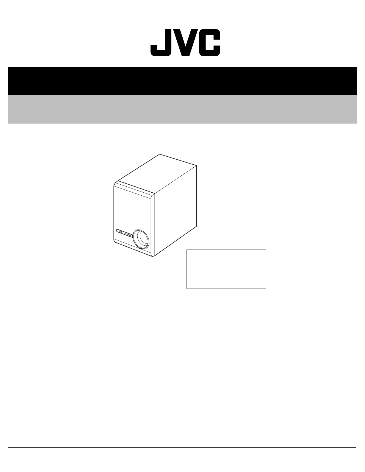
POWERED SUBWOOFER
MB23920044
SP-PWE5
Area suffix
B ------------------------------- U.K.
EV -------------- Eastern Europe
A ------------------------- Australia
TABLE OF CONTENTS
1 PRECAUTION. . . . . . . . . . . . . . . . . . . . . . . . . . . . . . . . . . . . . . . . . . . . . . . . . . . . . . . . . . . . . . . . . . . . . . . . . 1-3
2 SPECIFIC SERVICE INSTRUCTIONS . . . . . . . . . . . . . . . . . . . . . . . . . . . . . . . . . . . . . . . . . . . . . . . . . . . . . . 1-5
3 DISASSEMBLY . . . . . . . . . . . . . . . . . . . . . . . . . . . . . . . . . . . . . . . . . . . . . . . . . . . . . . . . . . . . . . . . . . . . . . . 1-6
4 ADJUSTMENT . . . . . . . . . . . . . . . . . . . . . . . . . . . . . . . . . . . . . . . . . . . . . . . . . . . . . . . . . . . . . . . . . . . . . . . 1-13
5 TROUBLESHOOTING . . . . . . . . . . . . . . . . . . . . . . . . . . . . . . . . . . . . . . . . . . . . . . . . . . . . . . . . . . . . . . . . . 1-14
COPYRIGHT © 2004 VICTOR COMPANY OF JAPAN, LIMITED
No.MB239
2004/4
Page 2
SPECIFICATION
Type Powered Subwoofer
Bass-reflex type
(magnetically shielded type)
Speaker 16.0 cm cone × 1
Frequency Range 25 Hz 200 Hz
Impedance 4 Ω
Input terminals INPUT (LOW-LEVEL)
Power requirements AC 230 V , 50 Hz
Output power of built-in amp 60 W (70 Hz, 4 Ω, 10 % THD)
Power Handling Capacity 30 W
Dimensions (W × H × D) 214 mm × 299 mm × 340 mm
Mass 8.1 kg
Design and specifications subject to change without notice.
1-2 (No.MB239)
Page 3
SECTION 1
PRECAUTION
1.1 Safety Precautions
(1) This design of this product contains special hardware and
many circuits and components specially for safety purposes. For continued protection, no changes should be made
to the original design unless authorized in writing by the
manufacturer. Replacement parts must be identical to
those used in the original circuits. Services should be performed by qualified personnel only.
(2) Alterations of the design or circuitry of the product should
not be made. Any design alterations of the product should
not be made. Any design alterations or additions will void
the manufacturers warranty and will further relieve the
manufacture of responsibility for personal injury or property
damage resulting therefrom.
(3) Many electrical and mechanical parts in the products have
special safety-related characteristics. These characteristics are often not evident from visual inspection nor can the
protection afforded by them necessarily be obtained by using replacement components rated for higher voltage, wattage, etc. Replacement parts which have these special
safety characteristics are identified in the Parts List of Service Manual. Electrical components having such features
are identified by shading on the schematics and by ( ) on
the Parts List in the Service Manual. The use of a substitute
replacement which does not have the same safety characteristics as the recommended replacement parts shown in
the Parts List of Service Manual may create shock, fire, or
other hazards.
(4) The leads in the products are routed and dressed with ties,
clamps, tubings, barriers and the like to be separated from
live parts, high temperature parts, moving parts and/or
sharp edges for the prevention of electric shock and fire
hazard. When service is required, the original lead routing
and dress should be observed, and it should be confirmed
that they have been returned to normal, after reassembling.
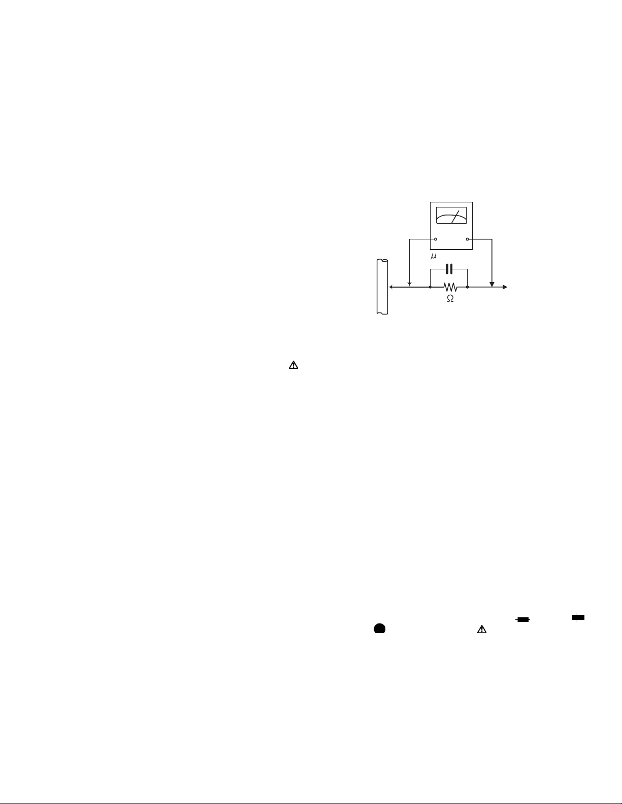
(5) Leakage shock hazard testing
After reassembling the product, always perform an isolation check on the exposed metal parts of the product (antenna terminals, knobs, metal cabinet, screw heads,
headphone jack, control shafts, etc.) to be sure the product
is safe to operate without danger of electrical shock.Do not
use a line isolation transformer during this check.
• Plug the AC line cord directly into the AC outlet. Using a
"Leakage Current Tester", measure the leakage current
from each exposed metal parts of the cabinet, particularly any exposed metal part having a return path to the
chassis, to a known good earth ground. Any leakage current must not exceed 0.5mA AC (r.m.s.).
• Alternate check method
Plug the AC line cord directly into the AC outlet. Use an
AC voltmeter having, 1,000Ω per volt or more sensitivity
in the following manner. Connect a 1,500Ω 10W resistor
paralleled by a 0.15µF AC-type capacitor between an ex-
posed metal part and a known good earth ground.
Measure the AC voltage across the resistor with the AC
voltmeter.
Move the resistor connection to each exposed metal
part, particularly any exposed metal part having a return
path to the chassis, and measure the AC voltage across
the resistor. Now, reverse the plug in the AC outlet and
repeat each measurement. Voltage measured any must
not exceed 0.75 V AC (r.m.s.). This corresponds to 0.5
mA AC (r.m.s.).
AC VOLTMETER
(Having 1000
ohms/volts,
or more sensitivity)
0.15 F AC TYPE
Place this
probe on
1500 10W
Good earth ground
1.2 Warning
(1) This equipment has been designed and manufactured to
meet international safety standards.
(2) It is the legal responsibility of the repairer to ensure that
these safety standards are maintained.
(3) Repairs must be made in accordance with the relevant
safety standards.
(4) It is essential that safety critical components are replaced
by approved parts.
(5) If mains voltage selector is provided, check setting for local
voltage.
1.3 Caution
Burrs formed during molding may be left over on some parts
of the chassis.
Therefore, pay attention to such burrs in the case of preforming repair of this system.
1.4 Critical parts for safety
In regard with component parts appearing on the silk-screen
printed side (parts side) of the PWB diagrams, the parts that are
printed over with black such as the resistor ( ), diode ( )
and ICP ( ) or identified by the " " mark nearby are critical
for safety. When replacing them, be sure to use the parts of the
same type and rating as specified by the manufacturer.
(This regulation dose not Except the J and C version)
each exposed
metal part.
(No.MB239)1-3
Page 4
1.5 Safety Precautions (U.K only)
(1) This design of this product contains special hardware and many circuits and components specially for safety purposes. For con-
tinued protection, no changes should be made to the original design unless authorized in writing by the manufacturer. Replacement parts must be identical to those used in the original circuits.
(2) Any unauthorised design alterations or additions will void the manufacturer's guarantee; furthermore the manufacturer cannot
accept responsibility for personal injury or property damage resulting therefrom.
(3) Essential safety critical components are identified by ( ) on the Parts List and by shading on the schematics, and must never
be replaced by parts other than those listed in the manual. Please note however that many electrical and mechanical parts in
the product have special safety related characteristics. These characteristics are often not evident from visual inspection. Parts
other than specified by the manufacturer may not have the same safety characteristics as the recommended replacement parts
shown in the Parts List of the Service Manual and may create shock, fire, or other hazards.
(4) The leads in the products are routed and dressed with ties, clamps, tubings, barriers and the like to be separated from live parts,
high temperature parts, moving parts and/or sharp edges for the prevention of electric shock and fire hazard. When service is
required, the original lead routing and dress should be observed, and it should be confirmed that they have been returned to
normal, after re-assembling.
1.5.1 Warning
(1) Service should be performed by qualified personnel only.
(2) This equipment has been designed and manufactured to meet international safety standards.
(3) It is the legal responsibility of the repairer to ensure that these safety standards are maintained.
(4) Repairs must be made in accordance with the relevant safety standards.
(5) It is essential that safety critical components are replaced by approved parts.
(6) If mains voltage selector is provided, check setting for local voltage.
Burrs formed during molding may be left over on some parts of the chassis. Therefore,
pay attention to such burrs in the case of preforming repair of this system.
1-4 (No.MB239)
Page 5

SECTION 2
SPECIFIC SERVICE INSTRUCTIONS
This service manual does not describe SPECIFIC SERVICE INSTRUCTIONS.
(No.MB239)1-5
Page 6

SECTION 3
DISASSEMBLY
3.1 Removing the amplifier assembly (See Figs.1 and 2)
(1) From the back side of the main body, remove the eleven
screws A attaching the amplifier assembly. (See Fig.1.)
(2) Take out the amplifier assembly from the main body.
(3) Disconnect the wire connectors from the back side of the
amplifier assembly. (See Fig. 2.)
3.2 Removing the back panel (See Figs.1 to 3)
(1) From the back side of the main body, remove the eleven
screws A attaching the amplifier assembly. (See Fig.1.)
Reference:
Remove the amplifier assembly as required. (See Fig.2.)
(2) Remove the screw B attaching the back panel. (See Fig.3.)
(3) Remove the back panel from the amplifier assembly.
Amplifier assembly
A
Main body
Wire connectors
Fig.2
Back panel
B
AA
1-6 (No.MB239)
A
Fig.1
Amplifier assembly
Amplifier assembly
Fig.3
Page 7

3.3 Removing the power board (See Fig.4)
• Prior to performing the following procedures, remove the back
panel.
• Remove the amplifier assembly as required.
(1) Remove the three screws C attaching the AC bracket.
(2) Take out the power board with the power cord and discon-
nect the wire from the connector CN899
board.
Reference:
When attaching the power board, insert the edge of the power
board in the groove a of the amplifier assembly.
on the power
Amplifier assembly
a
Power board
C
3.4 Removing the input board (See Figs.5)
• Prior to performing the following procedures, remove the back
panel.
• Remove the amplifier assembly as required.
(1) Disconnect the wire from the connector CN851
board.
(2) Remove the two screws D attaching the volume bracket.
(3) Disconnect the input board from the connector CN821
the amplifier board toward this side.
(4) Take out the input board from the amplifier assembly.
on the input
on
AC bracket
Power cord
CN899
C
Fig.4
Volume bracket
D
CN821
Input board
CN851
Amplifier assembly
Fig.5
(No.MB239)1-7
Page 8

3.5 Removing the amplifier board (See Fig.6)
• Prior to performing the following procedures, remove the back
panel and input board.
• Remove the amplifier assembly as required.
(1) Remove the five screws E and screw E' attaching the am-
plifier board.
(2) Take out the amplifier board and disconnect the wires from
the connectors (CN881
Reference:
• When attaching the screw E', attach the wire clamp with it.
• After attaching the amplifier board , fix the wire with the wire
clamp as before.
, CN891) on the amplifier board.
E
E
Amplifier board
E
CN881
Wire clamp
CN891
E'
Fig.6
1-8 (No.MB239)
Page 9

3.6 Removing the heat sink (See Figs.7 and 8)
• Prior to performing the following procedures, remove the back
panel, input board and amplifier board.
• Remove the amplifier assembly as required.
(1) From the reverse side of the amplifier board , bend the
claws b in the direction of the arrow. (See Fig.7.)
(2) From the forward side of the amplifier board , remove the
two screws F, screw G and screw G' attaching the heat
sink 1 and heat sink 2. (See Fig.8.)
Reference:
When attaching the screw G', attach the earth wire with it. (See
Fig.8.)
Amplifier board
b
b
Fig.7
Heat sink2
F
G
Amplifier board
Heat sink1
F
Earth wire
G'
Fig.8
(No.MB239)1-9
Page 10

3.7 Removing the power transformer (See Fig.9)
• Prior to performing the following procedures, remove the back
panel.
• Remove the amplifier assembly as required.
(1) Remove the tie bands bundling the wires.
(2) Disconnect the wire from the connector CN899
er board.
Reference:
Remove the power board as required.
(3) Disconnect the wire from the connector CN891
plifier board.
(4) Remove the four screws H attaching the power transformer
and take out the power transformer form the amplifier assembly.
Reference:
• When attaching the screws H, attach the washers with them.
• After attaching the power transformer, bundle the wires with
the new tie bands.
on the pow-
on the am-
CN899
Power
board
Amplifier board
Power
transformer
CN891
Tie
bands
HH
H
Fig.9
Washer
1-10 (No.MB239)
Page 11

3.8 Removing the ornament (See Figs.10 and 11)
(1) Insert the tip of a flat-bladed screwdriver or similar tool into
the space between the main body and ornament, and lift
the ornament little by little to remove the sections c. (See
Fig.10.)
Note:
To prevent damaging the ornament and main body, insert cushioning plates etc. into the space between the
main body and ornament. (See Fig.10.)
(2) From the inside of the ornament, disconnect the wire from
the connector CN061
3.9 Removing the LED board (See Fig.11)
(1) From the inside of the ornament, remove the two screws J
attaching the LED board.
(2) Take out the LED board from the ornament.
on the LED board. (See Fig.11.)
Ornament
Flat-bladed
screwdriver,etc.
Cushioning
c
plate, etc.
Fig.10
Ornament
LED board
J
J
Fig.11
CN061
Wire
(No.MB239)1-11
Page 12

3.10 Removing the cone speaker (See Figs.12 and 13)
• Prior to performing the following procedures, remove the orna-
ment.
(1) Remove the four screws K attaching the cone speaker.
(See Fig.12.)
(2) Take out the cone speaker from the main body. (See
Fig.12.)
(3) Disconnect the wire from the speaker terminals on the back
side of the cone speaker. (See Fig.13.)
K
KK
Cone speaker
Fig.12
Wire
Speaker terminals
1-12 (No.MB239)
Cone speaker
Fig.13
Page 13

SECTION 4
ADJUSTMENT
This service manual does not describe ADJUSTMENT.
(No.MB239)1-13
Page 14

SECTION 5
TROUBLESHOOTING
This service manual does not describe TROUBLESHOOTING.
1-14 (No.MB239)
Page 15

(No.MB239)1-15
Page 16

VICTOR COMPANY OF JAPAN, LIMITED
AV & MULTIMEDIA COMPANY AUDIO/VIDEO SYSTEMS CATEGORY 10-1,1chome,Ohwatari-machi,Maebashi-city,371-8543,Japan
(No.MB239)
Printed in Japan
WPC
 Loading...