

Page 1
SERVICE MANUAL
POWERED SUB WOOFER
MB25120046
SP-DWF10
J ---------------------------- U.S.A.
A ------------------------ Australia
E ---------- Continental Europe
US ------------------------ Singapore
UF ------------------------------ China
UP ----------------------------- Korea
UT ---------------------------- Taiwan
UX -------------------- Saudi Arabia
UJ ---------------------- U.S.Military
Area suffix
TABLE OF CONTENTS
1 PRECAUTION. . . . . . . . . . . . . . . . . . . . . . . . . . . . . . . . . . . . . . . . . . . . . . . . . . . . . . . . . . . . . . . . . . . . . . . . . 1-3
2 SPECIFIC SERVICE INSTRUCTIONS . . . . . . . . . . . . . . . . . . . . . . . . . . . . . . . . . . . . . . . . . . . . . . . . . . . . . . 1-5
3 DISASSEMBLY . . . . . . . . . . . . . . . . . . . . . . . . . . . . . . . . . . . . . . . . . . . . . . . . . . . . . . . . . . . . . . . . . . . . . . . 1-6
4 ADJUSTMENT . . . . . . . . . . . . . . . . . . . . . . . . . . . . . . . . . . . . . . . . . . . . . . . . . . . . . . . . . . . . . . . . . . . . . . . . 1-9
5 TROUBLESHOOTING . . . . . . . . . . . . . . . . . . . . . . . . . . . . . . . . . . . . . . . . . . . . . . . . . . . . . . . . . . . . . . . . . 1-10
COPYRIGHT © 2004 Victor Company of Japan, Limited
No.MB251
2004/6
Page 2
SPECIFICATION
Type Powered Subwoofer Bass-reflex type (magnetically shielded type)
Speaker 16.0 cm cone × 1 (6-5/16")
Frequency Range 32 Hz 200 Hz
Impedance 4 Ω
Input terminals INPUT (LOW-LEVEL)
Power requirements AC 120 V , 60 Hz
Output power of built-in amp 100 W (45 Hz, 4 Ω, 10 % THD)
Power Handling Capacity 25 W
Dimensions (W × H × D) 185 mm × 374 mm × 345 mm (7-5/16" × 14-3/4" × 13-5/8")
Mass 8.86 kg (19.6 lbs)
Design and specifications are subject to change without notice.
1-2 (No.MB251)
Page 3
SECTION 1
PRECAUTION
1.1 Safety Precautions
(1) This design of this product contains special hardware and
many circuits and components specially for safety purposes. For continued protection, no changes should be made
to the original design unless authorized in writing by the
manufacturer. Replacement parts must be identical to
those used in the original circuits. Services should be performed by qualified personnel only.
(2) Alterations of the design or circuitry of the product should
not be made. Any design alterations of the product should
not be made. Any design alterations or additions will void
the manufacturers warranty and will further relieve the
manufacture of responsibility for personal injury or property
damage resulting therefrom.
(3) Many electrical and mechanical parts in the products have
special safety-related characteristics. These characteristics are often not evident from visual inspection nor can the
protection afforded by them necessarily be obtained by using replacement components rated for higher voltage, wattage, etc. Replacement parts which have these special
safety characteristics are identified in the Parts List of Service Manual. Electrical components having such features
are identified by shading on the schematics and by ( ) on
the Parts List in the Service Manual. The use of a substitute
replacement which does not have the same safety characteristics as the recommended replacement parts shown in
the Parts List of Service Manual may create shock, fire, or
other hazards.
(4) The leads in the products are routed and dressed with ties,
clamps, tubings, barriers and the like to be separated from
live parts, high temperature parts, moving parts and/or
sharp edges for the prevention of electric shock and fire
hazard. When service is required, the original lead routing
and dress should be observed, and it should be confirmed
that they have been returned to normal, after reassembling.
(5) Leakage shock hazard testing
After reassembling the product, always perform an isolation check on the exposed metal parts of the product (antenna terminals, knobs, metal cabinet, screw heads,
headphone jack, control shafts, etc.) to be sure the product
is safe to operate without danger of electrical shock.Do not
use a line isolation transformer during this check.
• Plug the AC line cord directly into the AC outlet. Using a
"Leakage Current Tester", measure the leakage current
from each exposed metal parts of the cabinet, particularly any exposed metal part having a return path to the
chassis, to a known good earth ground. Any leakage current must not exceed 0.5mA AC (r.m.s.).
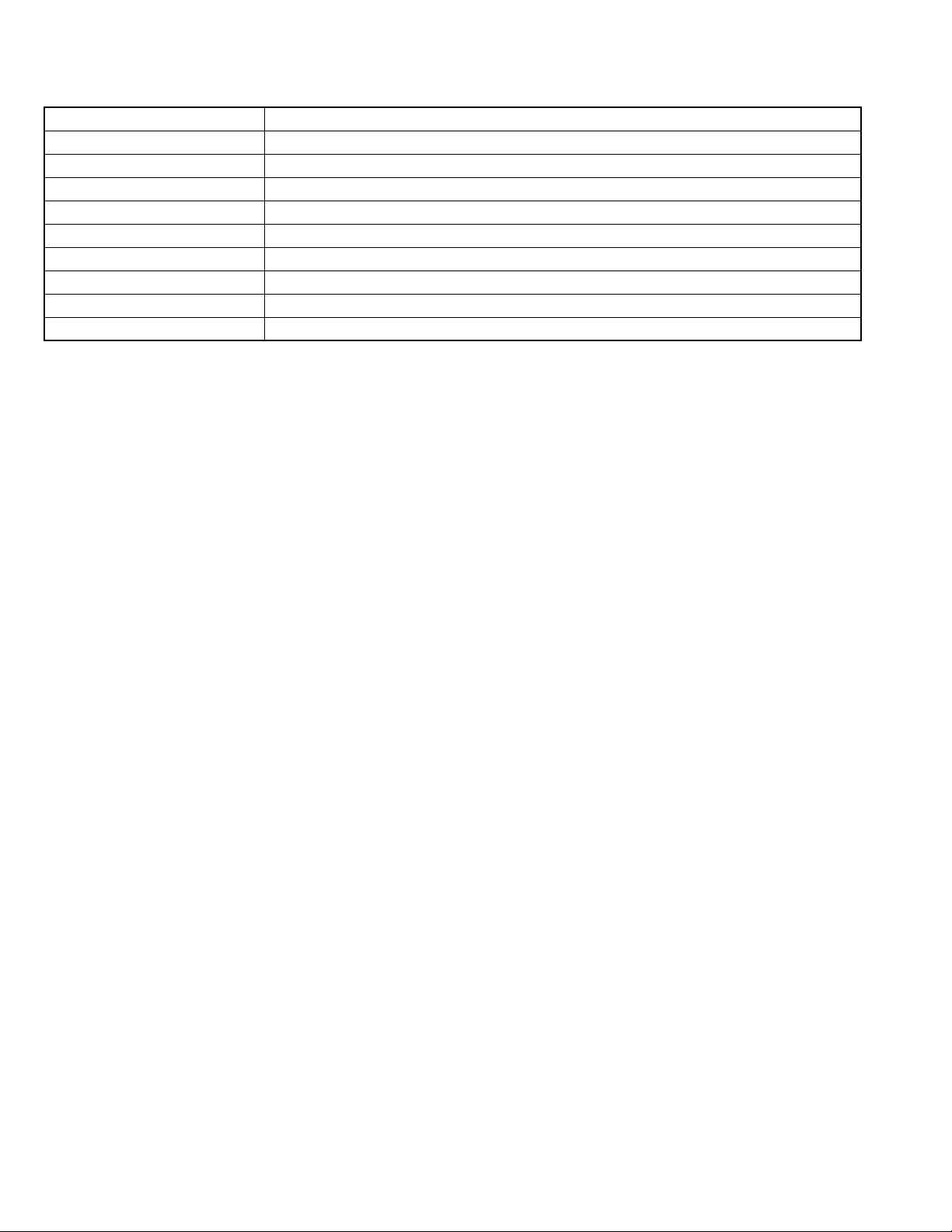
• Alternate check method
Plug the AC line cord directly into the AC outlet. Use an
AC voltmeter having, 1,000Ω per volt or more sensitivity
in the following manner. Connect a 1,500Ω 10W resistor
paralleled by a 0.15µF AC-type capacitor between an ex-
posed metal part and a known good earth ground.
Measure the AC voltage across the resistor with the AC
voltmeter.
Move the resistor connection to each exposed metal
part, particularly any exposed metal part having a return
path to the chassis, and measure the AC voltage across
the resistor. Now, reverse the plug in the AC outlet and
repeat each measurement. Voltage measured any must
not exceed 0.75 V AC (r.m.s.). This corresponds to 0.5
mA AC (r.m.s.).
AC VOLTMETER
(Having 1000
ohms/volts,
or more sensitivity)
0.15 F AC TYPE
Place this
probe on
1500 10W
Good earth ground
1.2 Warning
(1) This equipment has been designed and manufactured to
meet international safety standards.
(2) It is the legal responsibility of the repairer to ensure that
these safety standards are maintained.
(3) Repairs must be made in accordance with the relevant
safety standards.
(4) It is essential that safety critical components are replaced
by approved parts.
(5) If mains voltage selector is provided, check setting for local
voltage.
1.3 Caution
Burrs formed during molding may be left over on some parts
of the chassis.
Therefore, pay attention to such burrs in the case of preforming repair of this system.
1.4 Critical parts for safety
In regard with component parts appearing on the silk-screen
printed side (parts side) of the PWB diagrams, the parts that are
printed over with black such as the resistor ( ), diode ( )
and ICP ( ) or identified by the " " mark nearby are critical
for safety. When replacing them, be sure to use the parts of the
same type and rating as specified by the manufacturer.
(This regulation dose not Except the J and C version)
each exposed
metal part.
(No.MB251)1-3
Page 4
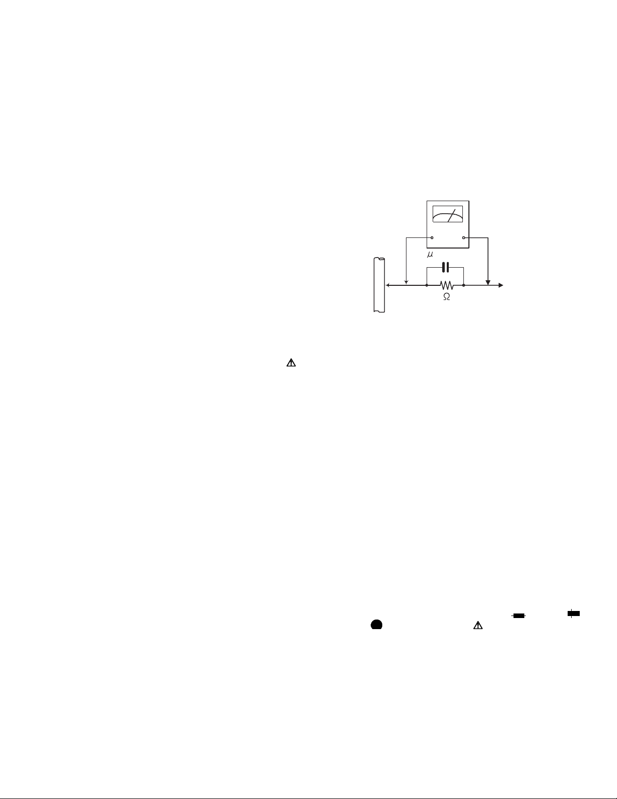
1.5 Importance administering point on the safety
Power switch board
F9001
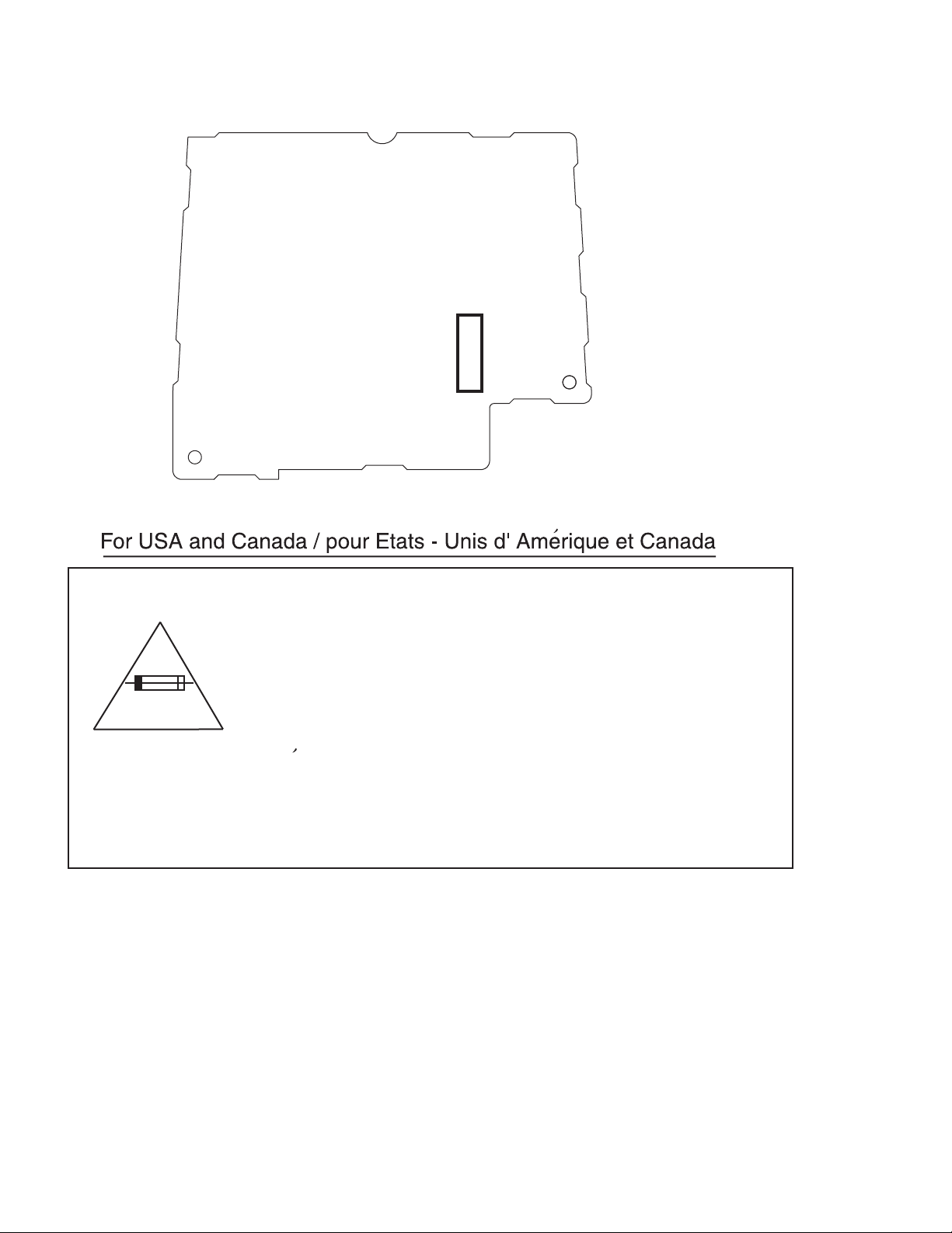
Caution: For continued protection against risk of fire,
replace only with same type 3 A/125 V for F901.
This symbol specifies the type of fast operating fuse.
Precaution: Pour la protection continue contre les
risques d'incendie, remplacer uniquement par le
meme type: fusible 3 A/125 V pour les F901.
^
Ce symbole specifie le type de fusible a action rapide.
1-4 (No.MB251)
Page 5

SECTION 2
SPECIFIC SERVICE INSTRUCTIONS
This service manual does not describe SPECIFIC SERVICE INSTRUCTIONS.
(No.MB251)1-5
Page 6
SECTION 3
A
DISASSEMBLY
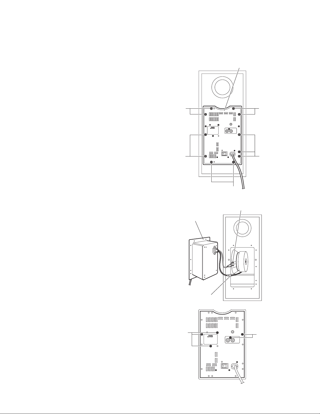
3.1 Removing the Amplifier assembly
(See Figs.1 and 2)
(1) From the back side of the main body, remove the eleven
screws A attaching the amplifier assembly. (See Fig.1.)
(2) Take out the amplifier assembly from the main body.
(3) Disconnect the wire connector from the back side of the
amplifier assembly. (See Fig. 2.)
(4) Disconnect the speaker wire from the speaker terminal.
(See Fig.2.)
Amplifier assembly
3.2 Removing the back panel
(See Figs.1 to 3)
(1) From the back side of the main body, remove the eleven
screws A attaching the amplifier assembly. (See Fig.1.)
Reference:
Remove the amplifier assembly from the main body as
required. (See Fig.2.)
(2) Remove the five screws B attaching the back panel. (See
Fig.3.)
A
A
mplifier assembly
A
A
A
Fig.1
Speaker terminal
1-6 (No.MB251)
Wire connector
B
Fig.2
B
Fig.3
Page 7
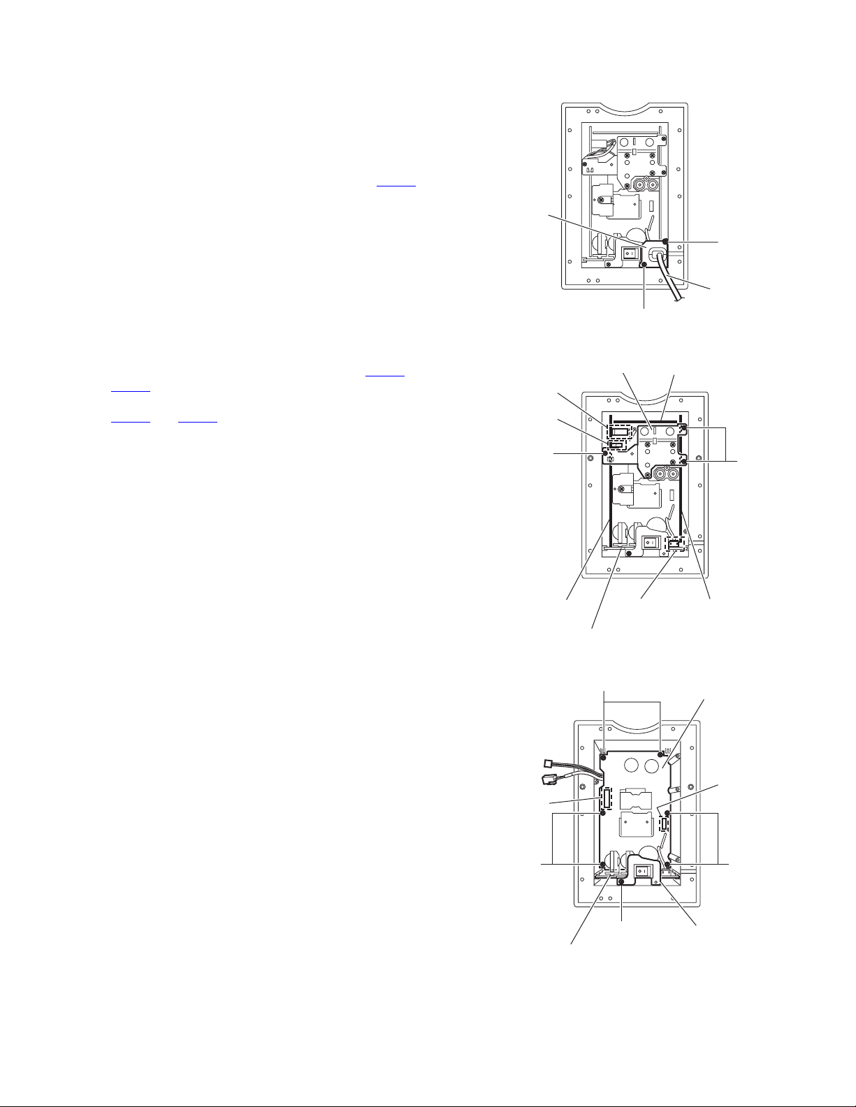
3.3 Removing the power cord
(See Figs.4 and 5)
• Prior to performing the following procedures, remove the back
panel.
(1) Remove the two screws C attaching the bracket a. (See
Fig.4.)
(2) Pull out the bracket a toward you.
(3) Disconnect the power cord from the connector CN901
the power switch board. (See Fig.5.)
3.4 Removing the amplifier board assembly (Amp board,
volume board, switch board)
(See Figs.5 and 6)
• Prior to performing the following procedures, remove the back
panel and the power cord.
• Remove the amplifier assembly from the main body as re-
quired. (See Figs.1 and 2.)
(1) Remove the three screws D attaching the bracket b. (See
Fig 5.)
(2) Disconnect the wire from the connectors CN102
on the amp board. (See Fig.5.)
CN503
(3) Remove the amplifier board assembly from the connectors
and CN952 on the regulator board. (See Fig.6.)
CN951
(4) Take out the amplifier board assembly.
on
and
Bracket a
CN503
CN102
Bracket b
C
Power cord
C
Fig.4
Volume board
3.5 Removing the power supply board assembly (Regulator board, power switch board)
(See Fig.6)
• Prior to performing the following procedures, remove the back
panel, power cord and amplifier board assembly.
• Remove the amplifier assembly from the main body as re-
quired. (See Figs.1 and 2.)
(1) Remove the screw E attaching the bracket c. (See Fig.6.)
(2) Remove the two screws F and four screws G attaching the
regulator board.
(3) Take out the power supply board assembly.
D
Amp board
CN951
CN901
Power switch board
Fig.5
F
D
Switch board
Regulator board
CN952
Power switch board
E
Fig.6
GG
Bracket c
(No.MB251)1-7
Page 8
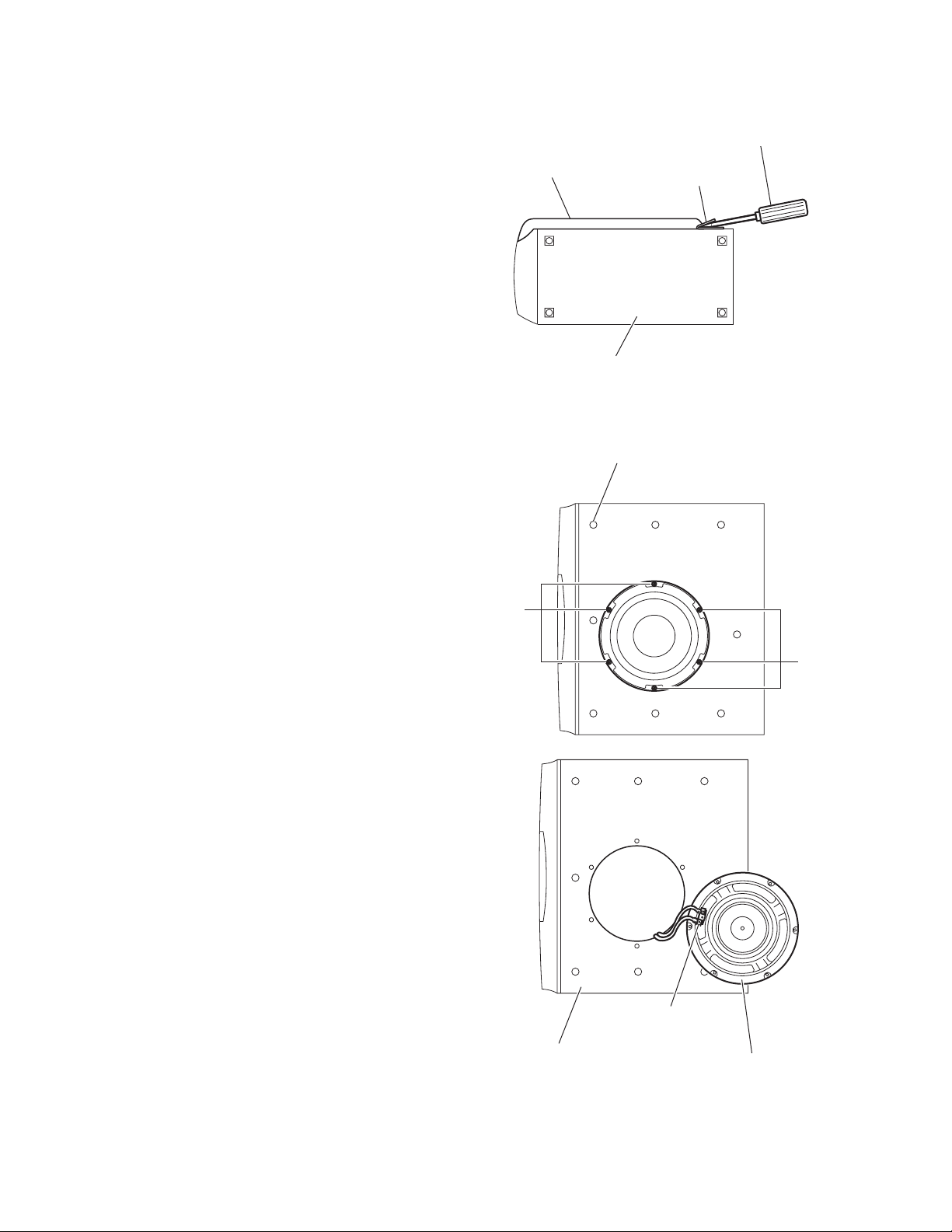
3.6 Removing the net assembly
(See Fig 7)
(1) From side of the main body, insert the tip of the flat-bladed
screwdriver or similar tool into the space between the main
body and net assembly, and lift the net assembly little by
little to remove. (See Fig 7)
Note:
To prevent damaging the net assembly and main body, insert
cushioning plates etc. and below the tip of the flat-bladed
screwdriver or similar tool.
From right side of the main body, release the eight joints d, and
take out the net assembly from the main body. (See Fig 7)
3.7 Removing the speaker.
(See Fig 8 and Fig 9)
• Prior to performing the following procedures, remove the net
assembly.
(1) Remove the six screws H attaching the speaker. (Fig 8)
(2) Take out the speaker from the main body.
(3) Disconnect the wires from the terminal of the speaker. (See
Fig 9)
Net assembly
Joint d (eight joints)
Flat-bladed
screwdriver,etc.
Cushioning
plate,etc.
Main body
Fig.7
H
Main body
H
Fig.8
Terminal
Speaker
Fig.9
1-8 (No.MB251)
Page 9

SECTION 4
ADJUSTMENT
This service manual does not describe ADJUSTMENT.
(No.MB251)1-9
Page 10

SECTION 5
TROUBLESHOOTING
This service manual does not describe TROUBLESHOOTING.
1-10 (No.MB251)
Page 11

(No.MB251)1-11
Page 12

Victor Company of Japan, Limited
AV & MULTIMEDIA COMPANY AUDIO/VIDEO SYSTEMS CATEGORY 10-1,1chome,Ohwatari-machi,Maebashi-city,371-8543,Japan
(No.MB251)
Printed in Japan
WPC
Page 13

SCHEMATIC DIAGRAMS
POWERED SUBWOOFER
SP-DWF10
CD-ROM No.SML200406
Area suffix
J ---------------------------- U.S.A.
A ------------------------ Australia
E ---------- Continental Europe
US ------------------------ Singapore
UF ------------------------------ China
UP ----------------------------- Korea
UT ---------------------------- Taiwan
UX -------------------- Saudi Arabia
UJ ---------------------- U.S.Military
Contents
Block diagram
Standard schematic diagram
Printed circuit boards
COPYRIGHT 2004 Victor Company of Japan, Limited.
2-1
2-2
2-3 to 4
No.MB251SCH
2004/6
Page 14

In regard with component parts appearing on the silk-screen printed side (parts side) of the PWB diagrams, the
parts that are printed over with black such as the resistor ( ), diode ( ) and ICP ( ) or identified by the " "
mark nearby are critical for safety.
(This regulation does not correspond to J and C version.)
Page 15

Block diagram
Volume board
IC501
Amp.
VR501
Off set
IC502
Comparator
IC503
IC504
Driver
VR502
Carrier Freq.
CN504
CN501
CN505
Amp board
IN
IC505
INV.
MUTE
LED
IC506
DRV.
IC571
INV.
+B
Q5006
Q5007
Q5706
REGULATOR
Q5902
Q5903
Q5904
Q5905
CN502
RY502
SPEAKER
OUT
CN503
CN102
CN861
RED GREEN
INDICATOR
J101
INPUT
Switch board
IC101
AMP
1/2
IC102
IC103
1/2
AMP
IC104 1/2
AUTO POWER ON
CANCEL / ON
MUTE
IC103
2/2
AMP
IC104 2/2
LED CONT.
CN101
Regulator board
POWER-SUPPLY
CIRCUIT
Power switch board
IC951
W9001 to 4
W9001 to 4
+B
CN951
T9501
TRANS
POWER
CN901
MAIN
PLUG
2-1
Page 16

Standard schematic diagram
W9001
W9002
W9003
W9004
J1001
QNN0090-001
!
C1002 C1001
0.001 0.001
R1002 R1001
C9501
!
C1003
10/50
C1004
10/50
470k 470k
K1001
NQR0129-003X
HA17558AF-X
( J/C) 470/200
R9501
CN901
QGA7901F2-02
!
R1003
56k
R1004
56k
IC101
2.2k
R1049
C1028
4.7/50
0.01
C1027
!
IC951
STR-F6676
C9502
K9501
QQR0779-001Z
R9502
0.33/1W
0.33/1W
F9001
!!
D8601
SPR325MVW
C1005
0.01
R1005
22K
C1009
47k
R1050
0.001/2K
D9501
AW04
!
R9503
680
0.01/275
IC101
HA17558AF-X
C1008
100/16
100/16
HA17558AF-X
R1051
C1029
1.2K
R1052
C9503
S9001
QSW1001-001
!
C9005
R9002
!
CN861
R8601
220
D8602
C1010
0.15
R1015
R1017
IC104
1M
47p
C9504
3.3k
470P
R9504
C9001
!
0.22/275
QQR1360-001 QQR1360-001
3.3M
C1011
0.15
R1021R1020
4.7K3.9K
12K
R1022
47
47
Q1002
2SC2412K
C1030
R1053
4.7k
4.7/50
0.01
47k
R1066
C1031
R9528
75K/1/4W
R9529
75K/1/4W
D9504
MTZJ20B
Q9504
D9503
2SC2412K
AG01Z
100/35
2.2k
R9505
D9502
AG01Z
D9505
C9505
470P
!!
LF901 LF902
R1023
R1048
1SS133
D1001
R9510
75K/1/4W
R9506
MTZJ20B
IC102
HA17558AF-X
68K
1k
2SC2412K
Q1003
2SC2412K
D9507 C9506
D9506
AG01Z
10k
C9002
!
C1013
100/16
Q1001
R1054
0.01/630
SARS03
R9508
22/1W
0.1/275
R1047
100K
!
S1001
QSW0834-001
56
!
PC951
PC123Y22
C9003C9004
!!
R1028
47
QAD0141-6R0
0.001/2500.001/250
47
R1025
C1012
100/16
R1046C1023
47K1/50
R1067
!
T9501
QQS0172-001
!
C9515
0.0033/250
!
D9001
!
TH901
R1030 R1031
7.5K 7.5K
1.5k
R1055
Q1004
2SA1037AK
56
10k
R1056
2.2k
R9527
RBV-606
R9001
100k/2W
Parts are safety assurance parts.
When replacing those parts make
sure to use the specified one.
C1015
0.22
IC103
HA17558AF-X
C1016
IC102
HA17558AF-X
47
C1033
R9516
MTZJ15A
2200/50
R9517
R9520
MTZJ15A
2200/50
R9521
10/16
R1064
13K
D9511
C9513
10k
13K10k
D9512
C9514
0.01
Q1007
2SC2412K
Q1006
2SA1037AK
47
R9518
0.01
R9522
10/50
10K
Q9508
2SA1514K
10k
Q9509
2SA1514K
R9524
4.7k
R9519
R9523
R9525
R1016
IC103
HA17558AF-X
22k
R1039
R1065
100
R1068
100
10k
1k
1k
C1014 R1032
0.082 680K
150K
100k
R1059
R1057
R1061
1M
IC104
HA17558AF-X
470/16
220k
C1034
C1032
R1060
D9509
FML-G22S
C9507
0.0047/1K
C9509
0.022/100
C9510
0.022/100
C9508
0.0047/1K
D9510
FML-G22S
W9001
W9002
W9003
W9004
R1062
10/16
C9511C9512
R1041
15K
C1021
100/16
C1020
0.0022
R1040
68K
C1022
QGB2016J1-05
CN103
CN952
QGB2016K1-05
Q9510
2SC2412K
10k
R9526
EP951
47
100/16
D1002
1SS133
D1003
1SS133
R1044
47
EP952
CN101
CN501
QGB2016K1-08
CN951
CN502
QGB2510J1-10
QGB2016J1-08
QGB2510K1-10
R5034
D5901
D5706
D5707
1SS355-X
R5733
10K
D5003
1SS133
R5036
10k
C5015
D5011D5012
R5902
MTZJ16B
Q5712
1SS355-X
2.2
R5037
R5038
TC74HC14AF-X
47p
D5004
0.01/100
C5901
M1FL20UM1FL20U
C5902
0.01/100
R5901
!
10/1/4W
Q5901
6.8k
2SD2395/EF/
C5905
4.7/25
KRA104S
R5720
R5721
47k
220k
Q5713
2SK303/3-4/-X
470k
R5734
C5708
2.2k 12K
IC504
10K
R5039
1SS133
D5013
1SS355
C5903
220/50
C5904
220/50
2.2k
C5704
R5723
R5722
IC571
TC74HC14AF-X
10k
R5735
R5736
3.3/10
C5918
C5917
0.01
47k
C5709
470k
0.018
0.018
D5709
R5737
0.082
C5024
D5710
1SS355-X
D5712
D5708
MA3300/L/
MA3200/H/
C5705
MA3200/H/
10k
R5738
C5710
2.2/10
R5059
11k
R5058
C5023
!
( D) QQR1352-001
15
R5061
15
R5060
15
15
R5063
R5062
R5701
1k
D5711
1SS355-X
0.01
R5739
100K
2.2/10
TC74HC00AF-W
180k
2.2/50
L5001
C5027C5028
C5702
39K
R5724
R5726
Q5714
68K
DTC115EKA-X
R5725
10k
D5715
R5740
IC503
0.1
C5012
22K
R5057
R5744
270P270P
0.0039/100
C5022
220/35
100k
R5727
D5713
R5729 R5728
68K
1SS355-X
47k
Q5720
KRA104S
C5913
10/16
NJM78L05A
IC591
C5916
10/16
D5905
MTZJ6.8B
Q5722
DTC144TKA
R5743
2.2k
390
K5001
QQR1183-001Z
D5703
1SS133
Q5706
2SC2412K
R5702
10k
100k
MA3300/L/
33K
C5914
10/16
C5915
10/16
D5906
MTZJ6.8B
RY502
QSK0149-001
AN79L05
IC592
QQR1183-001Z
K5002
CN102
QGA2501C1-02
CN503
QGA3901C1-02
R5021
15K
R5003
10k
10k
10K
R5002 R5001
R5004
C5001
100/16
R5005
10k
VR501
R5007
5K
13K
R5008
7.5K
R5006
10k
C5002
100/16
C5003
100/16
+13V
-13V
LED
+5V
-5V
MTZJ16BMTZJ16B
D5907
D5908
AHB
5.6k 1k
R5041 R5040
L5903 L5901
NQL114K-471X
C5911
100/25
C5912
100/25
L5904
NQL114K-471X
R5042
R5043
D5909
D5910
L5902
R5009
4.7
R5020
QGB2016J1-11
CN504
CN505
QGB2016K1-11
1k
Q5005
2SA1514K
R5044
560
3.3K
R5911
C5907
Q5904
RB160L-40-XRB160L-40-X
2SC2412K
Q5905
2SA1037AK
C5908
R5912
R5010
IC501
HA17558AF-X
10k
C5004
100/16
C5016
R5748R5747
Q5902
2SA1037AK
12K12K
220P220P
R5909
R5910
Q5903
2SC2412K
D5005
1SS133
R5045
56P
D5911
1SS355
D5912
1SS355
10k
R5012
10k
8.2K
100K100K
1K
1K
R5913R5914
R5011
10k
C5005
2SK303/3-4/-X
R5749
100K
C5711
0.22/25
330330
R5905
MTZJ15A
D5903
D5904
MTZJ15A
R5906
R5019
100/16
BU4584BF-X
D5006
1SS133
R5046
8.2K
C5017
Q5723
47K
C5909
C5910
47K
C5006
IC505
56P
C5025
R5013
4.7
R5014
1SS355-X
!
22/1/4W
100/50
100/50
22/1/4W
4.7k
4.7k
0.1
D5717
R5915
!
R5916
100/16
D5718
2.2k2.2K/1/4W
R5015
Q5001
2SA1037AK
Q5002
2SC2412K
R5016
1SS355-X
TH591
!
!
TH593
1K1K
R5017R5018
R5022
15K
R5713R5714
1SS355-X
Q5707
2SA1037AK
R5746
100K
TH592
!
NAD0032-330X
!
TH594
NAD0032-330X
NAD0032-330X
4.7
R5025
4.7
IC502
NJM311M-XE
R5023
100
0
0.022
470p
0.1
C5008
C5009
C5007
R5024
4.7
IR2113S-X
R5048
10k
D5007
MTZJ16B
0.22
C5018
Q5721
KRC104S-X
!
TH501
D5704
QAD0015-153Z
Q5708
KRC104S
47k
4.7k
R5715
Q5715
KRA104S-X
100k
D5716
1SS133
R5730
C5706
Q5717 Q5718 Q5719
DTC115EKA-X DTC115EKA-X KRC104S-X
3.3/10
NAD0032-330X
Q5716
KRC104S-X 10k
2SA1037AK
IC506
!
R5049
2.2/1/2W
Q5709
2SC2412K
R5731
R5732
100K
R5028
1k
Q5003
R5027
2.2
4.7
R5026
22/1/4W
C5703
R5029
Q5004
2SC4452/3-4/-X
R5050
R5717
47/16
R5716
6.8k
C5021
0.68
C5019
100k
0.22/100
220k
D5001D5002
R5030
C5026
4.7/100
C5020
10/50
R5051
!
Q5710
2SA1037AK
6.8k
R5718
1SS133
1SS133
R5031
R5032
!
10/1/2W
47k
R5033
4.7k
2.2k
R5053R5054
R5052
D5008
R5719
2.2
0.1
0.1
C5010
C5011
R5055
6.8/1W
1M1M
D5009
MTZJ18B
R5056
6.8/1W
22/1/2W
D5902
M1FL20U
Q5711
2SC2412K
47k
R5742
2.2
R5750
220K
R5035
0.1
C5013
D5010
MTZJ18B
MTZJ18B
R5745
VR502
2.2
IRFI540N
IRFI540N
C5906
C5014
22K
0.1
C5707
20K
680p
Q5006
Q5007
D5705
47/25
1SS355-X
1SS355-X
D5714
2-2
Page 17

Printed circuit boards
Main board
(Switch board)
CN101
R1016
C1016
C1015
R1031
S1001
J1001
C1001
C1002
R1001
K1001
R1002
C1004
C1003
R1003
R1004
C1010
C1028
C1032
R1017
R1049
C1033
C1027
R1032
R1020
C1009
C1011
R1021
IC101
R1066
C1030
R1062
R1022
C1031
C1034
C1014
R1053
R1064
R1060
R1030
R1059
R1025
R1005
Q1003
R1061
C1012
C1005
C1008
R1015
R1054
D1001
R1067
IC104
IC103
Q1007
R1023
D1003
D1002
IC102
C1023
Q1006
C1021 C1022
R1044
R1040
R1047
R1050
C1020
C1013
Q1004
R1056
R1052
R1039
R1041
Q1002
R1048
R1057
R1055
R1051
R1028
R1046
Q1001
C1029
R1065
CN103
R1068
R5719
D5707
R5723
CN502
D5709
D5706
R5915
TH501
R5715
R5714
R5713
D5704
Q5707
Q5708
C5909
C5910
R5721 R5722
Q5904
D5911
R5916
R5914
Q5709
R5717
Q5713
R5720
D5912
C5703
Q5710
R5718
Q5711
C5705
D5904
R5749
R5909
D5903
Q5905
R5906
Q5903
R5045
C5016
R5745
D5718
D5005
C5704
R5905
R5913
R5910
B8110
C5017
D5006
R5901
R5902
D5705
D5708
Q5902
B8111
Q5005
C5025
R5042
Q5723
Q5712
L5901
R5040
R5050
D5902
R5725
D5716
R5046
R5041
R5911
B8106
D5710
D5711
(Amp. board)
C5907
L5903
D5907 D5908
C5911 C5912
D5909
D5910
L5904
L5902
C5908
R5912
IC505
R5049
C5020
D5901
R5051
C5905
Q5901
C5906
R5726
R5724
R5727
R5728
D5713
Q5714
R5730
R5729
D5712
R5731
Q5721
R5043
B8112
C5706
B8102
R5747
R5702
R5701
R5044
Q5715
Q5716
Q5719
Q5717
Q5718
C5711
R5048
D5007
C5902
R5054
C5019
D5008
TH591
TH592
D5703
C5018
B8113
CN505
RY502
Q5706
C5903 C5904
R5056
R5748
C5022
C5901
R5055
R5052
TH593
TH594
D5717
C5702
R5053
IC506
C5021
C5024
K5002
C5027
R5732
R5741
D5013
L5001
R5062
R5750
R5733
B8103
R5742
C5707
K5001
C5028
C5026
C5709
Q5720
IC571
C5023
R5744
D5009
D5010
R5057
C5708
R5059
CN102
Q5006
Q5007
R5734
B8105
R5058
R5743
R5060
R5063
R5735
R5061
D5011
B8104
C5710
D5714
Q5722
C5918
R5736
R5740
D5715
B8107
R5746
C5917
D5012
R5737
R5738
R5716
CN503
R5739
D5906
IC592
TP501 VR501 VR502
C5914
C5913
R5035
C5010
R5029
R5037
D5003
C5915
R5030
R5033
R5032
Q5003
R5006
IC591
C5007
Q5004
C5916
C5015
D5905
R5027
D5002
R5038
R5031
R5036
C5014
R5024
D5001
C5009
R5026
C5002
R5025
R5039
C5008
R5023
R5028
C5011
D5004
(Volume board)
CN501
IC504
Q5002
IC502
CN504
C5013
B5101
IC503
C5006
R5021
R5016
C5012
R5019
C5005
R5007
R5034
R5014
R5018
R5013
R5009
R5015
Q5001
R5008
R5011
R5003
R5017
IC501
R5020
R5010
R5022
R5012
R5004
R5005
C5004
C5003
C5001
R5002
R5001
2-3
Page 18

Main board
(Regulator board)
W9004
EP951
CN952
HS953 HS952
T9501
C9515
R9508
D9506
D9504
Q9504
R9506
C9509
C9510
C9502
HS954
D9509 D9510
C9511 C9512
C9507 C9508
IC951
D9507
R9518
Q9508
R9519
Q9510
C9506
R9503
C9513
R9516
R9524
R9527
R9517
R9510
R9529
R9528
C9514
D9511
R9520
R9526
R9525
R9504
EP952
R9521
R9522
Q9509
R9523
CN951
PC951
D9512
W9004
W9002
CN901
W9002
D9505
C9501
W9003
(Power switch board)
C9003
4
0
0
9
C
TH901
Z9001 Z9002
R9002
C9005
C9001
C9504
K9501
W9001
R9505
W9003
D9001
C9505
D9501
W9001
D9503
R9501
R9502
C9503
D9502
R9001
C9002
2-4
S9001
LF902
LF901
Page 19

< MEMO >
Page 20

Victor Company of Japan, Limited
AV & MULTIMEDIA COMPANY AUDIO/VIDEO SYSTEMS CATEGORY 10-1,1chome,Ohwatari-machi,Maebashi-city,371-8543,Japan
(No.MB251SCH)
Printed in Japan
WPC
Page 21

PARTS LIST
[ SP-DWF10]
* All printed circuit boards and its assemblies are not available as service parts.
Area suffix
J ------------------------------ U.S.A.
A -------------------------- Australia
E ------------ Continental Europe
US ---------------------- Singapore
UF ---------------------------- China
UP ---------------------------- Korea
UT --------------------------- Taiwan
UX ------------------- Saudi Arabia
UJ --------------------- U.S.Military
MB251
- Contents -
Exploded view of general assembly and parts list (Block No.M1)
Electrical parts list (Block No.01)
Packing materials and accessories parts list (Block No.M3)
3- 2
3- 6
3-10
3-1
Page 22

Exploded view of general assembly and parts list
E
Block No.
M
43
M
1
M
41
47
41
53
42
J
51
45
48
49
50
16
15
46
52
J
3
7
A
B
3-2
D
Amp board
Page 23

38
38
61
59 60
J
A
oard
b
1
4
6
Volume board
E
B
A
62
26
27
4
Regulator board
G
4
F
39
40
17
b
20
a
20
58
56
2
4
18
57
55
D
10
28
Power
switch board
19
29
Switch board
26
F
Terminal board
9
12
12
C
a
5
b
54
26
28
44
11
14
C
21
13
G
8
13
4
25
22
24
23
25
29
30
32
32
37
33
34
35
31
36
3-3
Page 24

General Assembly
Symbol No. Part No. Part Name Description Local
Block No. [M][1][M][M]
1 LV21341-002A SHIELD DWF10J
1 LV21341-001A SHIELD
2 LV10709-002A COVER
3 LV30225-0R9A SPACER
4 LV30225-0S1A SPACER (x5)
5 LV30225-079A SPACER
6 LV30225-0E4A SPACER
7 LV30225-0R8A SPACER
8 LV30225-044A SPACER
9 QYSBSG3016E TAP SCREW M3 x 16mm(x2)
10 QYSBSF3008Z TAP SCREW M3 x 8mm(x4)
11 LV43179-002A BKT(SW)
12 LV30225-0H6A SPACER (x2)
13 LV30225-0H7A SPACER (x2)
14 QYSBSF2612M TAP SCREW M2.6 x 12mm
15 LV41148-002A CORD COVER
16 QYSBSF4012Z TAP SCREW M4 x 12mm(x2)
17 LV43178-001A BKT(CORD)
18 QZW0033-001 STRAIN RELIEF
19 QMPG150-244-JC POWER CORD(EU) 2.44m BLACK DWF10A
19 QMPD280-200-JC POWER CORD(EU) 2m BLACK DWF10J
19 QMPR480-200-JC POWER CORD(EU) 2m BLACK DWF10UF
19 QMPR310-200-JC POWER CORD(EU) 2m BLACK DWF10UP
19 QMPK190-200-JC POWER CORD(EU) 2m BLACK DWF10E,DWF10UJ,DWF10US
19 QMPR600-200-JD POWER CORD(EU) 2m BLACK DWF10UT
19 QMPR270-200-JD POWER CORD(EU) 2m BLACK DWF10UX
20 QYSBSF2612M TAP SCREW M2.6 x 12mm(x2)
21 LV33804-002A BKT(KNOB)
22 QYSBST3006Z TAP SCREW M3 x 6mm(x2)
23 E407321-002SM PUSH BUTTON
24 LV30225-0H5A SPACER
25 QYSBSF2612M TAP SCREW M2.6 x 12mm(x3)
26 LV30225-0H5A SPACER (x3)
27 LV30225-0E5A SPACER
28 LV30225-0E5A SPACER (x2)
29 LV30225-0A4A SPACER (x2)
30 LV30225-074A SPECER
31 LV21342-020A BACK PANEL DWF10A
31 LV21342-025A BACK PANEL DWF10E
31 LV21342-023A BACK PANEL DWF10J
31 LV21342-021A BACK PANEL DWF10UF
31 LV21342-024A BACK PANEL DWF10UJ
31 LV21342-019A BACK PANEL DWF10UP
31 LV21342-018A BACK PANEL DWF10US,DWF10UT
31 LV21342-022A BACK PANEL DWF10UX
32 LV30225-0H4A SPACER (x2)
33 LV30225-0H5A SPACER
34 QYSBSGY3008E TAP SCREW M3 x 8mm
35 QYSBSGY3008E TAP SCREW M3 x 8mm
36 QYSBSGY3008E TAP SCREW M3 x 8mm
37 QYSBSGY3008E TAP SCREW M3 x 8mm(x2)
38 QYSDSA4020M TAP SCREW M4 x 20mm(x11)
39 LV33803-001A HEAT SINK
40 QYSBSG3012Z TAP SCREW M3 x 12mm
41 LV30225-0G7A SPACER (x2)
42 LV30225-0G4A SPACER
43 LV43211-001A SPACER
44 QMF51E2-2R0-J1 FUSE 2A AC250V DWF10A,DWF10E
44 QMF51N2-3R0-J1 FUSE 3A AC250V DWF10J
44 QMF51E2-2R5-J1 FUSE 2.5A AC250V DWF10UF,DWF10UP
44 QMF51E2-3R15-J1 FUSE 3.15A AC250V
45 WJJ0098-001A E-SI C WIRE C-C
46 WJJ0390-001A E-SI C WIRE C-C DWF10J
46 WJN0095-001A E-SH C WIRE C-C
47 CR160063-01 CONE SPK
48 7001842004 SCREW (x6)
49 9916012101 ORNAMENT
50 9916012201 NET ASSY
51 5600006901 RUBBER FOOT (x4)
52 QQR0919-001 FERRITE CORE K 5003 DWF10J
53 LV43835-001A EMC LABEL DWF10J
54 QYSBSGY3008M TAP SCREW M3 x 8mm(x2)
DWF10A,DWF10E,DWF10UF,DWF10UJ,D
WF10UP,DWF10US,DWF10UT,DWF10UX
DWF10UJ,DWF10US,DWF10UT,DWF10U
X
DWF10A,DWF10E,DWF10UF,DWF10UJ,D
WF10UP,DWF10US,DWF10UT,DWF10UX
3-4
Page 25

Symbol No. Part No. Part Name Description Local
55 QYSBSG3010Z TAP SCREW M3 x 10mm
56 LV33802-001A HEAT SINK1 HS 951
57 E70306-001 HEAT SINK HS 954
58 QYSBSG3008Z TAP SCREW M3 x 8mm
59 E70306-001 HEAT SINK HS 952
60 E70306-001 HEAT SINK HS 953
61 QYSBSG3008Z TAP SCREW M3 x 8mm(x2)
62 VYSH101-034 SPACER
3-5
Page 26

Electrical parts list
Main board
Symbol No.
IC101 HA17558AF-X IC
IC102 HA17558AF-X IC
IC103 HA17558AF-X IC
IC104 HA17558AF-X IC
IC501 HA17558AF-X IC
IC502 NJM311M-XE IC
IC503 TC74HC00AF-W IC
IC504 TC74HC14AF-X IC
IC505 BU4584BF-X IC
IC506 IR2113S-X GATE DRIVER
IC571 TC74HC14AF-X IC
IC591 NJM78L05A-T IC
IC592 AN79L05-T IC
IC951 STR-F6656 IC
IC951 STR-F6676 IC
Q1001 2SC2412K/RS/-X TRANSISTOR
Q1002 2SC2412K/RS/-X TRANSISTOR
Q1003 2SC2412K/RS/-X TRANSISTOR
Q1004 2SA1037AK/RS/-X TRANSISTOR
Q1006 2SA1037AK/RS/-X TRANSISTOR
Q1007 2SC2412K/RS/-X TRANSISTOR
Q5001 2SA1037AK/RS/-X TRANSISTOR
Q5002 2SC2412K/RS/-X TRANSISTOR
Q5003 2SA1037AK/RS/-X TRANSISTOR
Q5004 2SC4452/3-4/-X TRANSISTOR
Q5005 2SA1514K/RS/-X TRANSISTOR
Q5006 IRFI540N FET
Q5007 IRFI540N FET
Q5706 2SC2412K/RS/-X TRANSISTOR
Q5707 2SA1037AK/RS/-X TRANSISTOR
Q5708 KRC104S-X TRANSISTOR
Q5709 2SC2412K/RS/-X TRANSISTOR
Q5710 2SA1037AK/RS/-X TRANSISTOR
Q5711 2SC2412K/RS/-X TRANSISTOR
Q5712 KRA104S-X DIGI TRANSISTOR
Q5713 2SK303/3-4/-X FET
Q5714 DTC115EKA-X DIGI TRANSISTOR
Q5715 KRA104S-X DIGI TRANSISTOR
Q5716 KRC104S-X TRANSISTOR
Q5717 DTC115EKA-X DIGI TRANSISTOR
Q5718 DTC115EKA-X DIGI TRANSISTOR
Q5719 KRC104S-X TRANSISTOR
Q5720 KRA104S-X DIGI TRANSISTOR
Q5721 KRC104S-X TRANSISTOR
Q5722 DTC144TKA-X TRANSISTOR
Q5723 2SK303/3-4/-X FET
Q5901 2SD2395/EF/ TRANTRANSISTOR
Q5902 2SA1037AK/RS/-X TRANSISTOR
Q5903 2SC2412K/RS/-X TRANSISTOR
Q5904 2SC2412K/RS/-X TRANSISTOR
Q5905 2SA1037AK/RS/-X TRANSISTOR
Q9504 2SC2412K/RS/-X TRANSISTOR
Q9508 2SA1514K/RS/-X TRANSISTOR
Q9509 2SA1514K/RS/-X TRANSISTOR
Q9510 2SC2412K/RS/-X TRANSISTOR
D1001 1SS133-T2 DIODE
D1002 1SS133-T2 DIODE
Part No. Part Name Description Local
Block No. [0][1]
DWF1
0J
DWF1
0A,D
WF10
E,DW
F10U
F,D W
F10UJ
,DWF
10UP,
DWF1
0US,D
WF10
UT,D
WF10
UX
Symbol No.
D1003 1SS133-T2 DIODE
D5001 1SS133-T2 DIODE
D5002 1SS133-T2 DIODE
D5003 1SS133-T2 DIODE
D5004 1SS133-T2 DIODE
D5005 1SS133-T2 DIODE
D5006 1SS133-T2 DIODE
D5007 MTZJ16B-T2 Z DIODE
D5008 M1FL20U-X FR DIODE
D5009 MTZJ18B-T2 Z DIODE
D5010 MTZJ18B-T2 Z DIODE
D5011 M1FL20U-X FR DIODE
D5012 M1FL20U-X FR DIODE
D5013 1SS355-X SI DIODE
D5703 1SS133-T2 DIODE
D5704 1SS355-X SI DIODE
D5705 1SS355-X SI DIODE
D5706 1SS355-X SI DIODE
D5707 1SS355-X SI DIODE
D5708 MA3200/H/-X Z DIODE
D5709 MA3200/H/-X Z DIODE
D5710 1SS355-X SI DIODE
D5711 1SS355-X SI DIODE
D5712 MA3300/L/-X Z DIODE
D5713 MA3300/L/-X Z DIODE
D5714 1SS355-X SI DIODE
D5715 1SS355-X SI DIODE
D5716 1SS133-T2 DIODE
D5717 1SS355-X SI DIODE
D5718 1SS355-X SI DIODE
D5901 MTZJ16B-T2 Z DIODE
D5902 MTZJ18B-T2 Z DIODE
D5903 MTZJ15A-T2 Z DIODE
D5904 MTZJ15A-T2 Z DIODE
D5905 MTZJ6.8B-T2 Z DIODE
D5906 MTZJ6.8B-T2 Z DIODE
D5907 MTZJ16B-T2 Z DIODE
D5908 MTZJ16B-T2 Z DIODE
D5909 RB160L-40-X SB DIODE
D5910 RB160L-40-X SB DIODE
D5911 1SS355-X SI DIODE
D5912 1SS355-X SI DIODE
D9001 RBV-606 BRIDGE DIODE
D9501 AW04-T2 SB DIODE
D9502 AG01Z-T2 DIODE
D9503 AG01Z-T2 DIODE
D9504 MTZJ20B-T2 Z DIODE
D9505 MTZJ20B-T2 Z DIODE
D9506 AG01Z-T2 DIODE
D9507 SARS03 SI DIODE
D9509 FML-G22S SI DIODE
D9510 FML-G22S SI DIODE
D9511 MTZJ15A-T2 Z DIODE
D9512 MTZJ15A-T2 Z DIODE
PC951 PC123Y22FZ PHOTO COUPLER
C1001 NCB31HK-102X C CAPACITOR 1000pF 50V K
C1002 NCB31HK-102X C CAPACITOR 1000pF 50V K
C1003 QETN1HM-106Z E CAPACITOR 10uF 50V M
C1004 QETN1HM-106Z E CAPACITOR 10uF 50V M
C1005 NCB31HK-103X C CAPACITOR 0.01uF 50V K
C1008 QERF1CM-107Z E CAPACITOR 100uF 16V M
C1009 QERF1CM-107Z E CAPACITOR 100uF 16V M
C1010 QFVF1HJ-154Z MF CAPACITOR 0.15uF 50V J
C1011 QFVF1HJ-154Z MF CAPACITOR 0.15uF 50V J
C1012 QEKC1CM-107Z E CAPACITOR 100uF 16V M
C1013 QEKC1CM-107Z E CAPACITOR 100uF 16V M
C1014 QFN31HJ-823Z M CAPACITOR 0.082uF 50V J
C1015 QFVF1HJ-224Z MF CAPACITOR 0.22uF 50V J
C1016 QETN1HM-106Z E CAPACITOR 10uF 50V M
C1020 NCB31HK-222X C CAPACITOR 2200pF 50V K
C1021 QEKC1CM-107Z E CAPACITOR 100uF 16V M
C1022 QEKC1CM-107Z E CAPACITOR 100uF 16V M
C1023 QERF1HM-105Z E CAPACITOR 1uF 50V M
C1027 NCB31HK-103X C CAPACITOR 0.01uF 50V K
Part No. Part Name Description Local
3-6
Page 27

Symbol No.
Part No. Part Name Description Local
Symbol No.
Part No. Part Name Description Local
C1028 QETN1HM-475Z E CAPACITOR 4.7uF 50V M
C1029 NCS31HJ-470X C CAPACITOR 47pF 50V J
C1030 QEKC1HM-475Z E CAPACITOR 4.7uF 50V M
C1031 NCB31HK-103X C CAPACITOR 0.01uF 50V K
C1032 QETN1CM-477Z E CAPACITOR 470uF 16V M
C1033 QEKC1CM-106Z E CAPACITOR 10uF 16V M
C1034 QEKC1CM-106Z E CAPACITOR 10uF 16V M
C5001 QERF1CM-107Z E CAPACITOR 100uF 16V M
C5002 QERF1CM-107Z E CAPACITOR 100uF 16V M
C5003 QERF1CM-107Z E CAPACITOR 100uF 16V M
C5004 QERF1CM-107Z E CAPACITOR 100uF 16V M
C5005 QERF1CM-107Z E CAPACITOR 100uF 16V M
C5006 QERF1CM-107Z E CAPACITOR 100uF 16V M
C5007 NCS31HJ-471X C CAPACITOR 470pF 50V J
C5008 NCB31HK-223X C CAPACITOR 0.022uF 50V K
C5009 NCB31EK-104X C CAPACITOR 0.1uF 25V K
C5010 NCB31EK-104X C CAPACITOR 0.1uF 25V K
C5011 QCBB1HK-104Y C CAPACITOR 0.1uF 50V K
C5012 NCB31EK-104X C CAPACITOR 0.1uF 25V K
C5013 QCBB1HK-104Y C CAPACITOR 0.1uF 50V K
C5014 NCS31HJ-681X C CAPACITOR 680pF 50V J
C5015 NCS31HJ-470X C CAPACITOR 47pF 50V J
C5016 NCS31HJ-560X C CAPACITOR 56pF 50V J
C5017 NCS31HJ-560X C CAPACITOR 56pF 50V J
C5018 NCB11EK-224X C CAPACITOR 0.22uF 25V K
C5019 NCB11EK-684X C CAPACITOR 0.68uF 25V K
C5020 QER61HM-106Z E CAPACITOR 10uF 50V M
C5021 QFV72AJ-224Z MF CAPACITOR 0.22uF 100V J
C5022 QFG32AJ-392Z PP CAPACITOR 3900pF 100V J
C5023 QENC1HM-225Z BP E CAPACITOR 2.2uF 50V M
C5024 NCB31CK-823X C CAPACITOR 0.082uF 16V K
C5025 NCF21HZ-104X C CAPACITOR 0.1uF 50V Z
C5026 QETN2AM-475Z E CAPACITOR 4.7uF 100V M
C5027 NCS31HJ-271X C CAPACITOR 270pF 50V J
C5028 NCS31HJ-271X C CAPACITOR 270pF 50V J
C5702 QETN1VM-227Z E CAPACITOR 220uF 35V M
C5703 QER61CM-476Z E CAPACITOR 47uF 16V M
C5704 NCB31HK-103X C CAPACITOR 0.01uF 50V K
C5705 NCB31HK-103X C CAPACITOR 0.01uF 50V K
C5706 NCB11AK-335X C CAPACITOR 3.3uF 10V K
C5707 NCB31EK-104X C CAPACITOR 0.1uF 25V K
C5708 NCB11AK-335X C CAPACITOR 3.3uF 10V K
C5709 NCB21AK-225X C CAPACITOR 2.2uF 10V K
C5710 NCB21AK-225X C CAPACITOR 2.2uF 10V K
C5711 NCB11EK-224X C CAPACITOR 0.22uF 25V K
C5901 QFV72AJ-103Z MF CAPACITOR 0.01uF 100V J
C5901 QFG32AJ-223Z PP CAPACITOR 0.022uF 100V J
C5902 QFV72AJ-103Z MF CAPACITOR 0.01uF 100V J
DWF1
0J,D
WF10
UT
DWF1
0J,D
WF10
UT
DWF1
0A,D
WF10
E,DW
F10J
DWF1
0UF,D
WF10
UJ,D
WF10
UP,D
WF10
US,D
WF10
UT,D
WF10
UX
DWF1
0A,D
WF10
E,DW
F10J
C5902 QFG32AJ-223Z PP CAPACITOR 0.022uF 100V J
C5903 QEHR1HM-227Z E CAPACITOR 220uF 50V M
C5904 QEHR1HM-227Z E CAPACITOR 220uF 50V M
C5905 QER61EM-475Z E CAPACITOR 4.7uF 25V M
C5906 QER61EM-476Z E CAPACITOR 47uF 25V M
C5907 NCS31HJ-221X C CAPACITOR 220pF 50V J
C5908 NCS31HJ-221X C CAPACITOR 220pF 50V J
C5909 QEHR1HM-107Z E CAPACITOR 100uF 50V M
C5910 QEHR1HM-107Z E CAPACITOR 100uF 50V M
C5911 QEHR1EM-107Z E CAPACITOR 100uF 25V M
C5912 QEHR1EM-107Z E CAPACITOR 100uF 25V M
C5913 QERF1CM-106Z E CAPACITOR 10uF 16V M
C5914 QERF1CM-106Z E CAPACITOR 10uF 16V M
C5915 QERF1CM-106Z E CAPACITOR 10uF 16V M
C5916 QERF1CM-106Z E CAPACITOR 10uF 16V M
C5917 NCB31HK-183X C CAPACITOR 0.018uF 50V K
C5917 NCB21HK-104X C CAPACITOR 0.1uF 50V K
C5918 NCB31HK-183X C CAPACITOR 0.018uF 50V K
C5918 NCB21HK-104X C CAPACITOR 0.1uF 50V K
C9001 QFZ9075-224 MPP CAPACITOR 0.22uF AC275V M
C9002 QFZ9075-104 MPP CAPACITOR 0.1uF AC275V M
C9003 QCZ9079-102 C CAPACITOR 1000pF AC250V M
C9004 QCZ9079-102 C CAPACITOR 1000pF AC250V M
C9005 QFZ9075-103 MPP CAPACITOR 0.01uF AC275V M
C9501 QEZ0602-477 E CAPACITOR 470uF
C9501 QEZ0603-227 E CAPACITOR 220uF
C9501 QEZ0603-477 E CAPACITOR 470uF
DWF1
0UF,D
WF10
UJ,D
WF10
UP,D
WF10
US,D
WF10
UT,D
WF10
UX
DWF1
0A,D
WF10
E
DWF1
0J,D
WF10
UF,D
WF10
UJ,D
WF10
UP,D
WF10
US,D
WF10
UT,D
WF10
UX
DWF1
0A,D
WF10
E
DWF1
0J,D
WF10
UF,D
WF10
UJ,D
WF10
UP,D
WF10
US,D
WF10
UT,D
WF10
UX
DWF1
0J
DWF1
0A,D
WF10
E,DW
F10U
F, DW
F10U
P
DWF1
0UJ,D
WF10
US,D
WF10
UT,D
WF10
UX
3-7
Page 28

Symbol No.
Part No. Part Name Description Local
Symbol No.
Part No. Part Name Description Local
C9502 QCZ0366-102 C CAPACITOR 1000pF
C9503 NCB31HK-471X C CAPACITOR 470pF 50V K
C9504 QETN1VM-107Z E CAPACITOR 100uF 35V M
C9505 NCB31HK-471X C CAPACITOR 470pF 50V K
C9506 QFKB2JK-103 MM CAPACITOR 0.01uF 630V K
C9507 QCZ0213-472 C CAPACITOR 4700pF 1kV K
C9508 QCZ0213-472 C CAPACITOR 4700pF 1kV K
C9509 QFG32AJ-223Z PP CAPACITOR 0.022uF 100V J
C9509 QFV72AJ-104Z MF CAPACITOR 0.1uF 100V J
C9510 QFG32AJ-223Z PP CAPACITOR 0.022uF 100V J
C9510 QFV72AJ-104Z MF CAPACITOR 0.1uF 100V J
C9511 QEHQ1HM-228 E CAPACITOR 2200uF 50V M
C9512 QEHQ1HM-228 E CAPACITOR 2200uF 50V M
C9513 NCB31HK-103X C CAPACITOR 0.01uF 50V K
C9514 NCB31HK-103X C CAPACITOR 0.01uF 50V K
C9515 QCZ9079-332 C CAPACITOR 3300pF AC250V M
R1001 NRSA63J-474X MG RESISTOR 470k
R1002 NRSA63J-474X MG RESISTOR 470k
R1003 NRSA63J-563X MG RESISTOR 56k
R1004 NRSA63J-563X MG RESISTOR 56k
R1005 NRSA63J-223X MG RESISTOR 22k
R1015 QRE141J-470Y C RESISTOR 47
R1016 NRSA63J-153X MG RESISTOR 15k
R1017 QRE141J-470Y C RESISTOR 47
R1020 NRSA63J-392X MG RESISTOR 3.9k
R1021 NRSA63J-472X MG RESISTOR 4.7k
R1022 NRSA63J-123X MG RESISTOR 12k
R1023 NRSA63J-683X MG RESISTOR 68k
R1025 QRE141J-470Y C RESISTOR 47
R1028 QRE141J-470Y C RESISTOR 47
R1030 NRSA63J-752X MG RESISTOR 7.5k
R1031 NRSA63J-752X MG RESISTOR 7.5k
R1032 NRSA63J-684X MG RESISTOR 680k
R1039 NRSA63J-223X MG RESISTOR 22k
R1040 NRSA63J-683X MG RESISTOR 68k
R1041 QRE141J-470Y C RESISTOR 47
R1044 QRE141J-470Y C RESISTOR 47
R1046 NRSA63J-473X MG RESISTOR 47k
R1047 NRSA63J-104X MG RESISTOR 100k
R1048 NRSA63J-102X MG RESISTOR 1k
R1049 NRSA63J-222X MG RESISTOR 2.2k
R1050 NRSA63J-473X MG RESISTOR 47k
R1051 NRSA63J-105X MG RESISTOR 1M
R1052 NRSA63J-122X MG RESISTOR 1.2k
R1053 NRSA63J-472X MG RESISTOR 4.7k
R1054 NRSA63J-560X MG RESISTOR 56
R1055 NRSA63J-152X MG RESISTOR 1.5k
R1056 NRSA63J-103X MG RESISTOR 10k
R1057 NRSA63J-154X MG RESISTOR 150k
R1059 NRSA63J-104X MG RESISTOR 100k
R1060 NRSA63J-224X MG RESISTOR 220k
Ω
1/16W J
Ω
1/16W J
Ω
1/16W J
Ω
1/16W J
Ω
1/16W J
Ω
1/4W J
Ω
1/16W J
Ω
1/4W J
Ω
1/16W J
Ω
1/16W J
Ω
1/16W J
Ω
1/16W J
Ω
1/4W J
Ω
1/4W J
Ω
1/16W J
Ω
1/16W J
Ω
1/16W J
Ω
1/16W J
Ω
1/16W J
Ω
1/4W J
Ω
1/4W J
Ω
1/16W J
Ω
1/16W J
Ω
1/16W J
Ω
1/16W J
Ω
1/16W J
Ω
1/16W J
Ω
1/16W J
Ω
1/16W J
Ω
1/16W J
Ω
1/16W J
Ω
1/16W J
Ω
1/16W J
Ω
1/16W J
Ω
1/16W J
DWF1
0A,D
WF10
E,DW
F10J
DWF1
0UF,D
WF10
UJ,D
WF10
UP,D
WF10
US,D
WF10
UT,D
WF10
UX
DWF1
0A,D
WF10
E,DW
F10J
DWF1
0UF,D
WF10
UJ,D
WF10
UP,D
WF10
US,D
WF10
UT,D
WF10
UX
R1061 NRSA63J-105X MG RESISTOR 1MΩ 1/16W J
R1062 QRE141J-470Y C RESISTOR 47
R1064 QRE141J-470Y C RESISTOR 47
R1065 QRE141J-101Y C RESISTOR 100
R1066 NRSA63J-473X MG RESISTOR 47k
R1067 NRSA63J-560X MG RESISTOR 56
R1068 QRE141J-101Y C RESISTOR 100
R5001 NRSA63J-153X MG RESISTOR 15k
R5002 NRSA63J-103X MG RESISTOR 10k
R5003 NRSA63J-103X MG RESISTOR 10k
R5004 NRSA63J-103X MG RESISTOR 10k
R5005 NRSA63J-103X MG RESISTOR 10k
R5006 NRSA63J-752X MG RESISTOR 7.5k
R5007 NRSA63J-133X MG RESISTOR 13k
R5008 NRSA63J-103X MG RESISTOR 10k
R5009 NRSA63J-103X MG RESISTOR 10k
R5010 NRSA63J-103X MG RESISTOR 10k
R5011 NRSA63J-103X MG RESISTOR 10k
R5012 NRSA63J-103X MG RESISTOR 10k
R5013 NRSA63J-472X MG RESISTOR 4.7k
R5014 NRSA63J-472X MG RESISTOR 4.7k
R5015 NRSA63J-222X MG RESISTOR 2.2k
R5016 QRE141J-222Y C RESISTOR 2.2k
R5017 NRSA63J-102X MG RESISTOR 1k
R5018 NRSA63J-102X MG RESISTOR 1k
R5019 NRSA63J-4R7X MG RESISTOR 4.7
R5020 NRSA63J-4R7X MG RESISTOR 4.7
R5021 NRSA63J-4R7X MG RESISTOR 4.7
R5022 NRSA63J-4R7X MG RESISTOR 4.7
R5023 NRSA63J-101X MG RESISTOR 100
R5024 NRSA63J-0R0X MG RESISTOR 0
R5025 NRSA63J-4R7X MG RESISTOR 4.7
R5026 NRSA63J-4R7X MG RESISTOR 4.7
R5027 NRSA63J-2R2X MG RESISTOR 2.2
R5028 NRSA63J-102X MG RESISTOR 1k
R5029 NRSA63J-682X MG RESISTOR 6.8k
R5030 NRSA63J-682X MG RESISTOR 6.8k
R5031 NRSA63J-472X MG RESISTOR 4.7k
R5032 NRSA63J-222X MG RESISTOR 2.2k
R5033 NRSA63J-2R2X MG RESISTOR 2.2
R5034 NRSA63J-2R2X MG RESISTOR 2.2
R5035 NRSA63J-2R2X MG RESISTOR 2.2
R5036 NRSA63J-103X MG RESISTOR 10k
R5037 NRSA63J-123X MG RESISTOR 12k
R5038 NRSA63J-222X MG RESISTOR 2.2k
R5039 NRSA63J-103X MG RESISTOR 10k
R5040 NRSA63J-102X MG RESISTOR 1k
R5041 NRSA63J-562X MG RESISTOR 5.6k
R5042 NRSA63J-102X MG RESISTOR 1k
R5043 NRSA63J-332X MG RESISTOR 3.3k
R5044 NRSA63J-561X MG RESISTOR 560
R5045 NRSA63J-822X MG RESISTOR 8.2k
R5046 NRSA63J-822X MG RESISTOR 8.2k
R5048 NRSA63J-103X MG RESISTOR 10k
R5049 QRZ9038-220X FUSI RESISTOR 22
R5050 QRZ9015-2R2X FUSI RESISTOR 2.2
R5051 QRZ9015-100X FUSI RESISTOR 10
R5052 QRZ9015-220X FUSI RESISTOR 22
R5053 NRSA63J-105X MG RESISTOR 1MΩ 1/16W J
R5054 NRSA63J-105X MG RESISTOR 1M
R5055 QRT01DJ-6R8X MF RESISTOR 6.8
R5056 QRT01DJ-6R8X MF RESISTOR 6.8
R5057 NRSA63J-223X MG RESISTOR 22k
R5058 NRSA63J-184X MG RESISTOR 180k
R5059 NRSA63J-113X MG RESISTOR 11k
R5060 NRSA02J-150X MG RESISTOR 15
R5061 NRSA02J-150X MG RESISTOR 15
R5062 NRSA02J-150X MG RESISTOR 15
Ω
1/4W J
Ω
1/4W J
Ω
1/4W J
Ω
1/16W J
Ω
1/16W J
Ω
1/4W J
Ω
1/16W J
Ω
1/16W J
Ω
1/16W J
Ω
1/16W J
Ω
1/16W J
Ω
Ω
1/16W J
Ω
1/16W J
Ω
1/16W J
Ω
1/16W J
Ω
1/16W J
Ω
1/16W J
Ω
Ω
Ω
Ω
Ω
1/16W J
Ω
1/16W J
Ω
1/16W J
Ω
1/16W J
Ω
1/16W J
Ω
1/16W J
Ω
1/16W J
Ω
1/16W J
Ω
1/16W J
Ω
1/16W J
Ω
1/16W J
Ω
1/16W J
Ω
Ω
Ω
Ω
Ω
1/16W J
Ω
1/16W J
Ω
1/16W J
Ω
1/16W J
Ω
1/16W J
Ω
Ω
1/16W J
Ω
1/16W J
Ω
Ω
1/16W J
Ω
Ω
1/16W J
Ω
Ω
Ω
1/16W J
Ω
Ω
Ω
Ω
Ω
1/16W J
Ω
1W J
Ω
1W J
Ω
1/16W J
Ω
Ω
1/16W J
Ω
1/10W J
Ω
1/10W J
Ω
1/10W J
1/16W J
1/16W J
1/16W J
1/16W J
1/4W J
1/16W J
1/16W J
1/16W J
1/16W J
1/16W J
1/16W J
1/16W J
1/16W J
1/16W J
1/16W J
DWF1
0J,D
WF10
UT
DWF1
0J,D
WF10
UT
DWF1
0J,D
WF10
UT
3-8
Page 29

Symbol No.
Part No. Part Name Description Local
Symbol No.
Part No. Part Name Description Local
R5063 NRSA02J-150X MG RESISTOR 15Ω 1/10W J
Ω
R5701 QRE141J-102Y C RESISTOR 1k
R5702 NRSA63J-103X MG RESISTOR 10k
R5713 NRSA63J-153X MG RESISTOR 15k
R5714 NRSA63J-473X MG RESISTOR 47k
R5715 NRSA63J-472X MG RESISTOR 4.7k
R5716 NRSA63J-224X MG RESISTOR 220k
R5717 NRSA63J-104X MG RESISTOR 100k
R5718 NRSA63J-473X MG RESISTOR 47k
R5719 NRSA63J-473X MG RESISTOR 47k
R5720 NRSA63J-222X MG RESISTOR 2.2k
R5721 NRSA63J-473X MG RESISTOR 47k
R5722 NRSA63J-473X MG RESISTOR 47k
R5723 NRSA63J-224X MG RESISTOR 220k
R5724 NRSA63J-393X MG RESISTOR 39k
R5725 NRSA63J-683X MG RESISTOR 68k
R5726 NRSA63J-104X MG RESISTOR 100k
R5727 NRSA63J-104X MG RESISTOR 100k
R5728 NRSA63J-333X MG RESISTOR 33k
R5729 NRSA63J-683X MG RESISTOR 68k
R5730 NRSA63J-104X MG RESISTOR 100k
R5731 NRSA63J-103X MG RESISTOR 10k
R5732 NRSA63J-104X MG RESISTOR 100k
R5733 NRSA63J-103X MG RESISTOR 10k
R5734 NRSA63J-474X MG RESISTOR 470k
R5735 NRSA63J-103X MG RESISTOR 10k
R5736 NRSA63J-474X MG RESISTOR 470k
R5737 NRSA63J-103X MG RESISTOR 10k
R5738 NRSA63J-104X MG RESISTOR 100k
R5739 NRSA63J-103X MG RESISTOR 10k
R5740 NRSA63J-473X MG RESISTOR 47k
R5741 NRSA63J-0R0X MG RESISTOR 0
R5742 NRSA63J-2R2X MG RESISTOR 2.2
R5743 NRSA63J-222X MG RESISTOR 2.2k
R5744 NRSA63J-391X MG RESISTOR 390
R5745 NRSA63J-223X MG RESISTOR 22k
R5746 NRSA63J-104X MG RESISTOR 100k
R5747 NRSA63J-104X MG RESISTOR 100k
R5748 NRSA63J-104X MG RESISTOR 100k
R5749 NRSA63J-104X MG RESISTOR 100k
R5750 NRSA63J-224X MG RESISTOR 220k
R5901 QRZ9005-100X FUSI RESISTOR 10
R5902 NRSA63J-682X MG RESISTOR 6.8kΩ 1/16W J
R5905 NRSA63J-473X MG RESISTOR 47k
R5906 NRSA63J-473X MG RESISTOR 47k
R5909 QRE141J-102Y C RESISTOR 1k
R5910 QRE141J-102Y C RESISTOR 1k
R5911 NRSA63J-123X MG RESISTOR 12k
R5912 NRSA63J-123X MG RESISTOR 12k
R5913 NRSA63J-331X MG RESISTOR 330
R5914 NRSA63J-331X MG RESISTOR 330
R5915 QRZ9038-220X FUSI RESISTOR 22
R5916 QRZ9038-220X FUSI RESISTOR 22
R9001 QRL027J-104 OMF RESISTOR 100kΩ 2W J
R9002 QRZ9037-335 COMP RESISTOR 3.3MΩ 1/2W K
R9501 QRT017J-R33 MF RESISTOR 0.33
R9502 QRT017J-R33 MF RESISTOR 0.33
R9503 QRZ9005-681X FUSI RESISTOR 680
R9504 NRSA63J-332X MG RESISTOR 3.3kΩ 1/16W J
R9505 NRSA63J-222X MG RESISTOR 2.2k
R9506 NRSA63J-103X MG RESISTOR 10k
R9508 QRL01DJ-220X OMF RESISTOR 22
R9510 QRE141J-753Y C RESISTOR 75k
R9516 NRSA63J-133X MG RESISTOR 13k
R9517 NRSA63J-103X MG RESISTOR 10k
R9518 NRSA63J-103X MG RESISTOR 10k
R9519 NRSA63J-103X MG RESISTOR 10k
R9520 NRSA63J-133X MG RESISTOR 13k
R9521 NRSA63J-103X MG RESISTOR 10k
R9522 NRSA63J-103X MG RESISTOR 10k
R9523 NRSA63J-102X MG RESISTOR 1k
R9524 NRSA63J-472X MG RESISTOR 4.7k
R9525 NRSA63J-102X MG RESISTOR 1k
R9526 NRSA63J-103X MG RESISTOR 10k
R9527 NRSA63J-222X MG RESISTOR 2.2k
R9528 QRE141J-753Y C RESISTOR 75k
1/4W J
Ω
1/16W J
Ω
1/16W J
Ω
1/16W J
Ω
Ω
Ω
Ω
1/16W J
Ω
1/16W J
Ω
Ω
1/16W J
Ω
1/16W J
Ω
Ω
1/16W J
Ω
1/16W J
Ω
Ω
Ω
1/16W J
Ω
1/16W J
Ω
Ω
1/16W J
Ω
Ω
1/16W J
Ω
Ω
1/16W J
Ω
Ω
1/16W J
Ω
Ω
1/16W J
Ω
1/16W J
Ω
1/16W J
Ω
1/16W J
Ω
Ω
1/16W J
Ω
1/16W J
Ω
Ω
Ω
Ω
Ω
Ω
Ω
1/16W J
Ω
1/16W J
Ω
1/4W J
Ω
1/4W J
Ω
1/16W J
Ω
1/16W J
Ω
1/16W J
Ω
1/16W J
Ω
Ω
Ω
Ω
Ω
Ω
Ω
1/16W J
Ω
1W J
Ω
1/4W J
Ω
1/16W J
Ω
1/16W J
Ω
1/16W J
Ω
1/16W J
Ω
1/16W J
Ω
1/16W J
Ω
1/16W J
Ω
1/16W J
Ω
Ω
1/16W J
Ω
1/16W J
Ω
Ω
1/4W J
1/16W J
1/16W J
1/16W J
1/16W J
1/16W J
1/16W J
1/16W J
1/16W J
1/16W J
1/16W J
1/16W J
1/16W J
1/16W J
1/16W J
1/16W J
1/16W J
1/16W J
1/16W J
1/16W J
1/16W J
1/16W J
1W J
1W J
DWF1
0J,D
WF10
UT
R9529 QRE141J-753Y C RESISTOR 75kΩ 1/4W J
VR501 QVP0008-502Z TRIM RESISTOR 5k
VR502 QVP0008-203Z TRIM RESISTOR 20k
L5001 QQR1361-001 TOROIDAL COIL
L5901 NQL114K-471X COIL 470uH K
L5902 NQL114K-471X COIL 470uH K
L5903 NQL114K-471X COIL 470uH K
L5904 NQL114K-471X COIL 470uH K
T9501 QQS0172-001 SW TRANSF
BK501 LV33818-001A BKT(FET)
CN101 QGB2016K1-08 CONNECTOR B-B (1-8)
CN102 QGA2501C1-02 CONNECTOR W-B (1-2)
CN103 QGB2016J1-05 CONNECTOR B-B (1-5)
CN501 QGB2016J1-08 CONNECTOR B-B (1-8)
CN502 QGB2510K1-10 CONNECTOR B-B (1-10)
CN503 QGA3901C1-02 CONNECTOR W-B (1-2)
CN504 QGB2016J1-11 CONNECTOR B-B (1-11)
CN505 QGB2016K1-11 CONNECTOR B-B (1-11)
CN901 QGA7901F2-02 CONNECTOR W-B (1-2)
CN951 QGB2510J1-10 CONNECTOR B-B (1-10)
CN952 QGB2016K1-05 CONNECTOR B-B (1-5)
EP951 QNZ0136-001Z EARTH PLATE
EP952 QNZ0136-001Z EARTH PLATE
J1001 QNN0090-001 PIN JACK
K1001 NQR0129-003X FERRITE BESDA
K5001 QQR1183-001Z FERRITE BEADS
K5002 QQR1183-001Z FERRITE BEADS
K9501 QQR0779-001Z COIL
LF901 QQR1360-001 LINE FILTER
LF902 QQR1360-001 LINE FILTER
RY502 QSK0149-001 RELAY
S1001 QSW0834-001 PUSH SW
S9001 QSW1001-001 POWER SW
TH501 QAD0015-153Z THERMISTOR 15k
TH591 NAD0032-330X P THERMISTOR 33
TH592 NAD0032-330X P THERMISTOR 33
TH593 NAD0032-330X P THERMISTOR 33
TH594 NAD0032-330X P THERMISTOR 33
TH901 QAD0143-5R1 THERMISTOR 5.1
TH901 QAD0141-6R0 THERMISTOR 6
Z9001 QNG0003-001Z FUSE CLIP
Z9002 QNG0003-001Z FUSE CLIP
Ω
Ω
Ω
Ω
Ω
Ω
Ω
Ω
Ω
DWF1
0J
DWF1
0A,D
WF10
E,DW
F10U
F, DW
F10UJ
,DWF
10UP,
DWF1
0US,D
WF10
UT,D
WF10
UX
3-9
Page 30

Packing materials and accessories parts list
Block No.
P2
A1A3 A6
US, UJ
M
3
M
M
P7
P2
A1A2 A3
P5
A, E, UP,
A
P3
A4
P2
A1A3
A11A12
J
P6
P2
A1A3 A5
UT, UX
P2
A1A2 A3
A7
A8 A9
A10
UF
3-10
P4
P1
Page 31

Packing and Accessories
Block No. [M][3][M][M]
Symbol No. Part No. Part Name Description Local
A 1 LVT1145-007A INST BOOK ENG DWF10A
A 1 LVT1145-002C INST BOOK GER FRE DUT SPA ITA SWE FIN DAN DWF10E
A 1 LVT1145-010A INST BOOK ENG DWF10J
A 1 LVT1145-009A INST BOOK CHI(PEKIN) DWF10UF
A 1 LVT1145-006A INST BOOK ENG SPA CHI(PEKIN) POR ARA DWF10UP
A 1 LVT1145-004A INST BOOK KOR DWF10UJ,DWF10US
A 1 LVT1145-008A INST BOOK CHI(TAIWAN) DWF10UT
A 1 LVT1145-005A INST BOOK ENG ARA PER DWF10UX
A 2 BT-56012-1 WARRANTY CARD DWF10A
A 2 BT-54008-6 WARRANTY CARD DWF10E
A 2 BT-59019-1 WARRANTY CARD DWF10UF
A 2 BT-56013-1 WARRANTY CARD DWF10UP
A 3 QAM0570-001 PIN CABLE
A 4 SPDWF10E-SPBOX SPK WITH BOX
A 5 QAM0027-002 CONVERSION PLUG DWF10UT,DWF10UX
A 6 QAM0112-002 PLUG ADAPTOR DWF10UJ,DWF10US
A 7 BT-59020-1 SEAL DWF10UF
A 8 BT-59021-2 SVC CENTER LIST DWF10UF
A 9 E310162-001 CERTIFICATE TAG DWF10UF
A 10 GN30020-003A SURVEY CARD DWF10UF
A 11 YU20333 SAFETY INST. DWF10J
A 12 BT-51034-2 J=REGIST CARD DWF10J
P 1 LV31492-060A CARTON DWF10A
P 1 LV31492-070A CARTON DWF10E
P 1 LV35232-003A CARTON DWF10UF
P 1 LV31492-090A CARTON DWF10J,DWF10UJ
P 1 LV31492-058A CARTON DWF10UP,DWF10US,DWF10UT
P 1 LV31492-059A CARTON DWF10UX
P 2 QPA02503503P POLY BAG 25cm x 35cm
P 3 QPA07007505P POLY BAG 70cm x 75cm
P 3 LV34587-001A POLY BAG DWF10US,DWF10UT,DWF10UX
P 4 8500051801 MIRROR MAT
P 5 8000055101 TOP CUSHION
P 6 8000055111 BOTTOM CUSHION
P 7 LV33489-010A CARTON SHEET DWF10A
DWF10A,DWF10E,DWF10J,DWF10UF,DW
F10UJ,DWF10UP
3-11
 Loading...