

Page 1
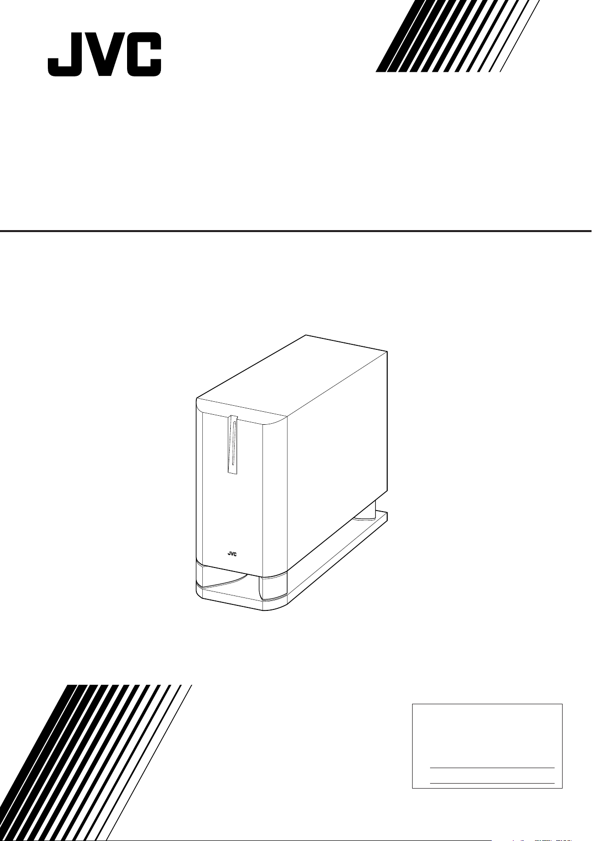
POWERED SUBWOOFER
For Customer Use:
Enter below the Model No. and Serial
No. which are located either on the rear,
bottom or side of the cabinet. Retain this
information for future reference.
Model No.
Serial No.
SP-DW103
English
INSTRUCTIONS
– 1 –
LVT1030-001A
[J]
Page 2
Warnings, Cautions, and Others/
CAUTION: TO REDUCE THE RISK OF ELECTRIC SHOCK.
DO NOT REMOVE COVER (OR BACK)
NO USER SERVICEABLE PARTS INSIDE.
REFER SERVICING TO QUALIFIED SERVICE PERSONNEL.
RISK OF ELECTRIC SHOCK
DO NOT OPEN
The lightning flash with arrowhead symbol,
within an equilateral triangle is intended to
alert the user to the presence of uninsulated
"dangerous voltage" within the product's
enclosure that may be of sufficient
magnitude to constitute a risk of electric
shock to persons.
The exclamation point within an equilateral
triangle is intended to alert the user to the
presence of important operating and
maintenance (servicing) instructions in the
literature accompanying the appliance.
CAUTION
WARNING: TO REDUCE THE RISK OF FIRE
OR ELECTRIC SHOCK, DO NOT EXPOSE
THIS APPLIANCE TO RAIN OR MOISTURE.
For Canada/pour le Canada
CAUTION: TO PREVENT ELECTRIC SHOCK, MATCH WIDE
BLADE OF PLUG TO WIDE SLOT, FULLY INSERT
ATTENTION: POUR EVITER LES CHOCS ELECTRIQUES,
INTRODUIRE LA LAME LA PLUS LARGE DE LA FICHE DANS LA
BORNE CORRESPONDANTE DE LA PRISE ET POUSSER
JUSQUAU FOND
THIS DIGITAL APPARATUS DOES NOT EXCEED THE CLASS
B LIMITS FOR RADIO NOISE EMISSIONS FROM DIGITAL
APPARATUS AS SET OUT IN THE INTERFERENCE-CAUSING
EQUIPMENT STANDARD ENTITLED “DIGITAL APPARATUS,”
ICES-003 OF THE DEPARTMENT OF COMMUNICATIONS.
CET APPAREIL NUMERIQUE RESPECTE LES LIMITES DE
BRUITS RADIOELECTRIQUES APPLICABLES AUX
APPAREILS NUMERIQUES DE CLASSE B PRESCRITES
DANS LA NORME SUR LE MATERIEL BROUILLEUR;
“APPAREILS NUMERIQUES”, NMB-003 EDICTEE PAR LE
MINISTRE DES COMMUNICATIONS.
For U.S.A
This equipment has been tested and found to comply with the limits
for a Class B digital device, pursuant to part 15 of the FCC Rules.
These limits are designed to provide reasonable protection against
harmful interference in a residential installation.
This equipment generates, uses and can radiate radio frequency
energy and, if not installed and used in accordance with the
instructions, may cause harmful interference to radio
communications. However, there is no guarantee that interference
will not occur in a particular installation. If this equipment does cause
harmful interference to radio or television reception, which can be
determined by turning the equipment off and on, the user is
encouraged to try to correct the interference by one or more of the
following measures:
Reorient or relocate the receiving antenna.
Increase the separation between the equipment and receiver.
Connect the equipment into an outlet on a circuit different from that
to which the receiver is connected.
Consult the dealer or an experienced radio/TV technician for help.
Changes or modifications not expressly approved by the
manufacturer for compliance could void the user’s authority to
operate the equipment.
Mises en garde, précautions et indications diverses
English
CAUTION
To reduce the risk of electrical shocks, fire, etc.:
1. Do not remove screws, covers or cabinet.
2. Do not expose this appliance to rain or moisture.
ATTENTION
Afin d’éviter tout risque d’électrocution, d’incendie, etc.:
1. Ne pas enlever les vis ni les panneaux et ne pas ouvrir le
coffret de l’appareil.
2. Ne pas exposer l’appareil à la pluie ni à l’humidité.
Caution—POWER switch
This apparatus is provided with the POWER switch to
minimize power consumption for safe use. Therefore,
1. Before doing initial settings, complete all the connections
required, connect the mains plug into the wall outlet, then
set the POWER switch to ON [ ❙ ].
2. When not in use, set the POWER switch to OFF [ ‡ ].
This disconnects the mains line.
Précaution—Interrupteur POWER
Cet appareil possède un interrupteur POWER permettant
de réduire la consommation électrique et d’assurer une
utilisation en toute sécurité. Par conséquent:
1. Avant de réaliser les réglages initiaux, effectuez toutes
les connexions nécessaires, connectez la fiche
d’alimentation sur une prise secteur murale, puis mettez
l’interrupteur POWER sur la position ON [ ❙ ].
2. Quand l’appareil n’est pas utilisé, mettez l’interrupteur
POWER sur la position OFF [ ‡ ].
De cette façon, l’appareil est déconnecté du secteur.
– 2 –
Page 3
Precautions for installation
• To prevent deformation or discoloration
of the cabinet, do not install the unit
where it is exposed to direct sunlight or
high humidity, and avoid installation near
air conditioning outlets.
Precautions for Daily Use
• To maintain the appearance of the unit
Wipe with a dry, soft cloth if the cabinet or control
panel should become dirty.
If very dirty, apply a small amount of water or
neutral detergent to the cloth and wipe clean. Then
wipe with a dry cloth.
English
• Speaker vibrations may cause howling.
Place the unit as far away from the
player as possible.
• Take the occurrence of earthquakes or
other physical shocks into consideration
when selecting the installation place,
and secure the unit thoroughly.
• This unit is magnetically shielded to avoid color
distortions on TVs. However, if not installed
properly, it may cause color distortions. So, pay
attention to the following when installing the unit.
– When placing this unit near a TV set, turn off the
TV’s main power switch or unplug it before
installing this unit.
Then wait at least 30 minutes before turning on
the TV’s main power switch again.
Some TVs may still be affected even though you
have followed the above. If this happens, move this
unit away from the TV.
• To improve the sound field
If the speakers are facing a solid wall or
glass door, etc., it is recommended to
furnish the wall with materials that
absorb sounds, for example by hanging
up thick curtains, to prevent reflections
and standing waves.
Checking the Supplied Accessories
Check to be sure you have the following supplied
accessories.
The number in parenthesis indicates the quantity of
the piece supplied.
• Monaural audio cord (1)
If the item mentioned above is missing, contact your
dealer immediately.
• Tuner reception may become noisy or hissing if this
unit is installed nearby the tuner. In this case, leave
a more distance between the tuner and this unit or
use an outdoor antenna for better tuner reception
without interference from this unit.
CONTENTS
Warnings, Cautions and Others ............................................................... 2
Connections............................................................................................ 4
Checking Your Amplifier ............................................................................ 4
Connecting to the Amplifier ...................................................................... 4
Operations .............................................................................................. 6
Additional Information ........................................................................... 8
Speaker layout.......................................................................................... 8
Troubleshooting ........................................................................................ 9
Specifications ........................................................................................... 9
– 3 –
Page 4
Connections
SUBWOOFER
OUT
LINE OUT
L
R
RIGHT
LEFT
FRONT SPEAKERS
2
1
SUBWOOFER
OUT
RIGHT LEFT/MONO
(LOW-LEVEL)
INPUT 1
TO MAIN
SPEAKERS
RIGHT
RIGHT LEFT
RIGHT LEFT
LEFT/MONO
MAX
VOLUME
50Hz
200Hz
MIN
ONOFF
FIXED
VARIABLE
POWER
FREQUENCY
CUT OFF FILTER
INPUT 2
(HIGH-LEVEL)
(LOW-LEVEL)
INPUT 1
AUTO POWER ON/STANDBY
PHASE
CANCEL
ON
REVERSE
NORMAL
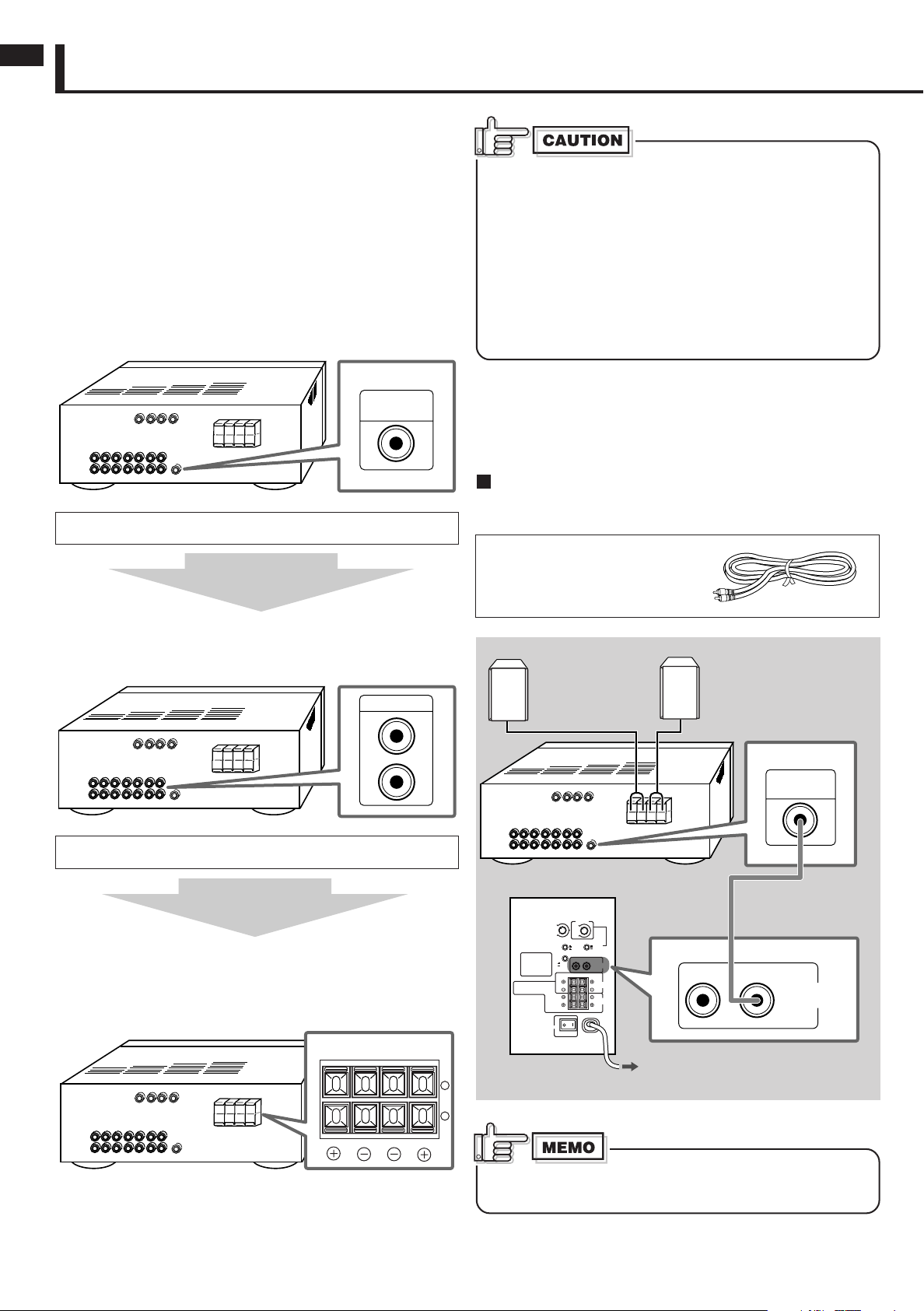
Checking Your Amplifier
English
Before connecting this unit to your amplifier (or receiver), check
what types of connecting terminals your amplifier has.
Follow the instructions below to find a proper connection method
for your equipment.
• Illustrations of jacks and terminals in this manual may be
different from the ones actually used for your amplifier. The
illustrations are of the most used type.
First check whether your amplifier has a subwoofer output
jack.
It is usually named and printed as the “SUBWOOFER OUT” or
“SUBWOOFER.”
If you find it on your amplifier, follow Connecting Method Å.
If you cannot
find any
Before connecting this unit to the amplifier (or receiver),
observe the following carefully.
• Before connecting this unit to an amplifier, turn off the
amplifier first.
• Make all connections before plugging in this unit.
• DO NOT use the INPUT 1 (LOW-LEVEL) and INPUT 2
(HIGH-LEVEL) terminals on the rear of this unit at the
same time; otherwise, noise will be heard and may
damage the unit.
• DO NOT connect this unit to the REC OUT jacks of your
amplifier.
Connecting to the Amplifier
When connecting to your amplifier (or receiver), refer also the
manual supplied for your equipment.
Connecting Method Å
Connect an amplifier having a subwoofer output jack to the
LEFT/MONO jack of the INPUT 1 (LOW-LEVEL) terminal.
Preparation:
Use the supplied monaural
audio cord.
Next check whether your amplifier has line output jacks.
They are usually named and printed as “LINE OUT” or “LINE
OUTPUT.”
If you find them on your amplifier, follow Connecting Method ı.
If you cannot
find any
Follow Connecting Method Ç.
This connection can be used for any amplifier, by connecting the
front speaker terminals of the amplifier (usually named and
printed as “FRONT SPEAKERS” or “MAIN SPEAKERS”).
Main (Front) Speakers
(not supplied)
Your Amplifier
SP-DW103
To an AC outlet
Monaural audio cord
(supplied)
When using Connecting Method Å, no signal comes out of
the TO MAIN SPEAKERS terminal.
– 4 –
Page 5

TO MAIN
SPEAKERS
RIGHT
RIGHT LEFT
RIGHT LEFT
LEFT/MONO
MAX
VOLUME
50Hz
200Hz
MIN
ONOFF
FIXED
VARIABLE
POWER
FREQUENCY
CUT OFF FILTER
RIGHT
LEFT
FRONT SPEAKERS
TO MAIN
SPEAKERS
INPUT 2
(HIGH-LEVEL)
RIGHT LEFT
RIGHT LEFT
INPUT 2
(HIGH-LEVEL)
(LOW-LEVEL)
INPUT 1
AUTO POWER ON/STANDBY
PHASE
CANCEL
ON
REVERSE
NORMAL
2
1
Connecting Method ı
TO MAIN
SPEAKERS
RIGHT
RIGHT LEFT
RIGHT LEFT
LEFT/MONO
MAX
VOLUME
50Hz
200Hz
MIN
ONOFF
FIXED
VARIABLE
POWER
FREQUENCY
CUT OFF FILTER
LINE OUT
L
R
RIGHT LEFT/MONO
(LOW-LEVEL)
INPUT 1
INPUT 2
(HIGH-LEVEL)
(LOW-LEVEL)
INPUT 1
AUTO POWER ON/STANDBY
PHASE
CANCEL
ON
REVERSE
NORMAL
123
Connect an amplifier having line output jacks to the INPUT 1
(LOW-LEVEL) terminal.
Preparation:
Purchase a stereo audio cord at
an audio shop or electric shop.
Main (Front) Speakers
(not supplied)
English
Your Amplifier
Speaker cords
(not supplied)
SP-DW103
To an AC
outlet
Your Amplifier
Stereo audio cord
(not supplied)
SP-DW103
If your amplifier has only a monaural line output (MONO)
jack, connect it to the LEFT/MONO jack of the INPUT 1
(LOW-LEVEL) terminal (see Connecting Method Å).
Connecting Method Ç
Connect an amplifier without a subwoofer output jack and line
output jacks to the INPUT 2 (HIGH-LEVEL) terminal.
• When this method is used, connect your main (front) speakers
to the TO MAIN SPEAKERS terminal on the rear of this unit.
Preparation:
Purchase speaker cords at an
audio shop or electric shop.
To an AC outlet
Speaker cords
(not supplied)
Main (Front) Speakers
(not supplied)
Right speaker
Left speaker
How to connect the speaker cords:
1 Press and hold the clamp of the speaker terminal.
2 Insert the end of the speaker cord into the terminal as
illustrated below.
• Match the polarity of the speaker terminals: ª to ª and ·
to ·.
3 Release the finger from the clamp.
• When you connect main (front) speakers to the TO MAIN
SPEAKERS terminal, use the speakers within the
impedance range indicated by the amplifier connected to
the INPUT 2 (HIGH-LEVEL) terminal. If not, the amplifier
connected to the INPUT 2 (HIGH-LEVEL) terminal may
malfunction and be damaged.
• DO NOT connect more than one speaker to one speaker
terminal.
– 5 –
Page 6
Operations
MAX
VOLUME
MIN
MAX
VOLUME
MIN
TO MAIN
INPUT 2
(HIGH-LEVEL)
(LOW-LEVEL)
RIGHT
RIGHT LEFT
RIGHT LEFT
LEFT/MONO
MAX
VOLUME
50Hz
200Hz
MIN
CANCEL
ON
ONOFF
REVERSE
NORMAL
FIXED
VARIABLE
INPUT 1
POWER
FREQUENCY
AUTO POWER ON/STANDBY
PHASE
CUT OFF FILTER
Å
Ç
ı
Ç
Î
‰
POWER
PHASE
AUTO POWER
ON/STANDBY
VOLUME
FREQUENCY
CUT OFF
FILTER
SPEAKERS
English
Front view
Rear view
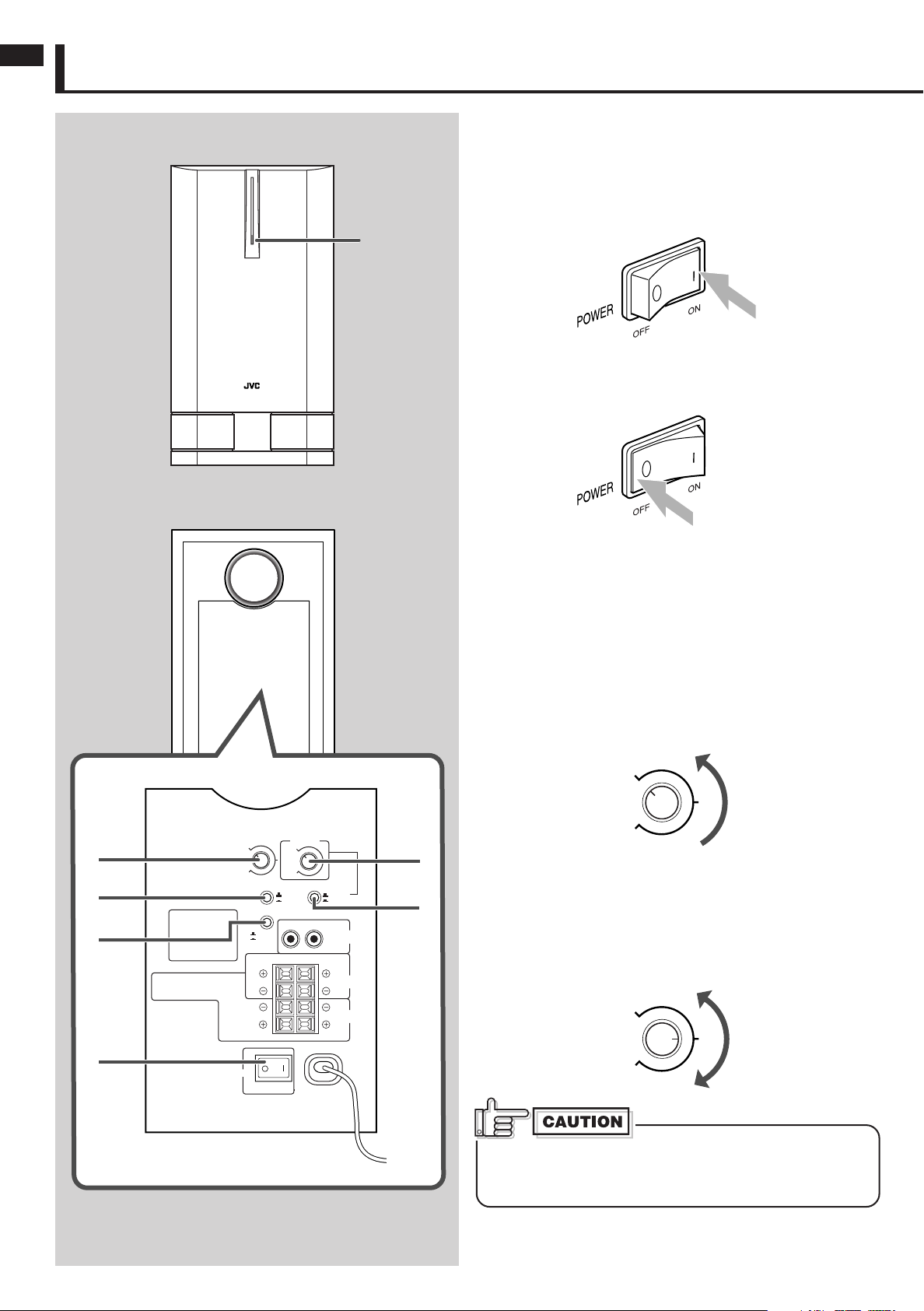
Turning On the Power—POWER Å
Press the ON [ ❙ ] portion of the POWER switch.
The main power turns on and the power lamp in the front panel
lights in green.
• The power lamp lights in red when the Auto Power On/
Standby places the unit into standby mode (see page 7).
Power
lamp
To completely cut off the power to this unit
Press the OFF [ ‡ ] portion of the POWER switch.
This will disconnect the mains lead.
Adjusting the Volume—VOLUME ı
Adjust the volume output level through this unit while comparing
with the sounds coming out of the main (front) speakers.
• Once you have adjusted the volume output level of this unit,
you do not need to adjust it each time you use this unit.
Adjusting the volume level on the connected amplifier will also
adjust the volume level through this unit.
1 Turn the VOLUME knob to the MIN position.
2 Turn on the connected amplifier and start playing a
source.
Playback sounds come out of the main (front) speakers and
this unit.
3 Adjust the VOLUME knob to obtain a well-balanced sound
level with that of the main (front) speakers.
If the volume is set at a high level before starting play, the
sudden blast of sound energy can permanently damage
your hearing and/or ruin your speakers.
– 6 –
Page 7
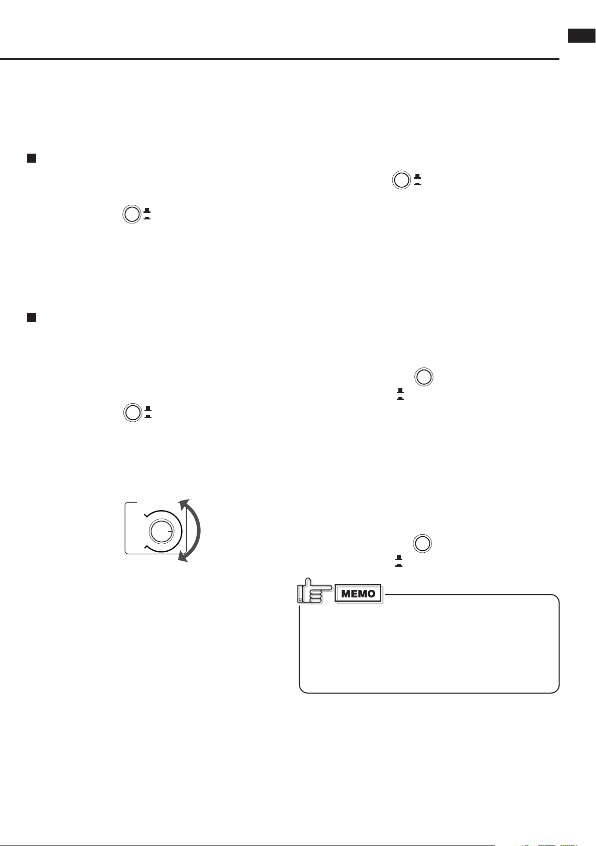
Adjusting the Crossover Frequency
200Hz
FREQUENCY
50Hz
FIX
VARIABLE
CUT OFF FILTER
REVERSE
NORMAL
PHASE
CANCEL
ON
AUTO POWER ON / STANDBY
CANCEL
ON
AUTO POWER ON / STANDBY
FIX
VARIABLE
CUT OFF FILTER
—CUT OFF FILTER and FREQUENCY Ç
You can adjust the crossover frequency to determine the bass
sound level this unit handles.
• Once it is set, only the sounds below the frequency come out
of the built-in speaker.
When the main speakers in use are JVC’s SX-XD33
Press in the CUT OFF FILTER button to set it to the _ FIX
position.
• The FREQUENCY knob is deactivated.
• When your amplifier is equipped with crossover frequency
setting, set it within the range of 100 Hz to 150 Hz.
• When your amplifier is equipped with speaker size setting,
select “small.”
If your amplifier is not provided with a crossover
frequency setting:
1 Press out the CUT OFF FILTER button to set it to the —
VARIABLE position.
Now the FREQUENCY knob is activated and you can adjust
the crossover frequency on this unit.
Changing the Phase—PHASE Î
You can change the sound phase to match your preference.
Select either “NORMAL” or “REVERSE” to obtain a better bass
sound.
Press in or out the PHASE button to select either the
NORMAL position or the REVERSE position.
• NORMAL : Normally select this.
• REVERSE: Select this when you feel the bass sound is better
with this mode rather than with “NORMAL.”
Operating the Unit Automatically According to the
Incoming Signals—AUTO POWER ON/STANDBY ‰
By using this function, this unit automatically enters standby
mode even though the POWER switch is turned ON [ ❙ ].
Press the AUTO POWER ON/STANDBY button to the — ON
position.
English
2 Turn the FREQUENCY knob to obtain the best matching
crossover frequency with your main speakers.
Adjust the frequency (50 Hz to 200 Hz) while listening to
playback sound coming out of both the main speakers and this
unit.
• If your main speakers can reproduce the bass sound well,
adjust the frequency at a lower level.
• If you feel bass sounds are not sufficient, adjust the
frequency at a higher level.
• If no sound comes in for about 10 minutes, the unit
automatically enters standby mode. The power lamp lights in
red. Then if the unit detects incoming signals, this unit starts
operating automatically (the power lamp now lights in green).
If Auto Power On/Standby does not work correctly (see
“MEMO” below), press out the AUTO POWER ON/STANDBY
button to set it to the _ CANCEL position. Auto Power On/
Standby is canceled.
When the volume level of the amplifier is so low or the
incoming signals are so weak that this unit cannot detect
sounds, Auto Power On/Standby may not work correctly.
• This unit may enter standby mode even though signals
are coming in.
• This unit may not start operating after entering standby
mode, even though signals start coming in.
– 7 –
Page 8

Additional Information
Subwoofer
Left front
speaker
Right front
speaker
Center
speaker
Listening position
Left surround
speaker
Right surround
speaker
Speaker layout
English
To obtain the best possible sound from your unit:
—Place a subwoofer wherever you like since bass sound is non-
directional. Normally place it in front of you.
—Place all the main speakers at the same distance from the
listening position.
– 8 –
Page 9

Troubleshooting
Use this chart to help you solve daily operational problems. If there is any problem you cannot solve, contact your dealer.
English
Symptom
Power does not come on.
Auto Power On/Standby does not
function correctly.
No sound is heard.
Sounds fluctuate (suddenly
become loud or soft).
Suddenly no sound comes out.
—the power lamp lights in red.
Suddenly no sound comes out.
—the power lamp still lights in
green.
Possible Cause
Is the unit pugged in?
Signals are too weak or volume
level is too low.
Is the VOLUME knob turned to
the MIN position?
Connections are incorrect, or
loose.
Audio signals through the
amplifier are extremely weak.
The built-in protective circuit is
working.
The VOLUME knob on the rear is
set to a very high level.
The volume of the playback
source is too high.
Action
Plug the AC power cord firmly into the
AC outlet.
This is not a malfunction. If this
happens, cancel Auto Power On/
Standby.
Turn the VOLUME knob until a
suitable volume is found.
Check the connections. If incorrect,
redo the corrections. (See pages 4
and 5.)
Increase the volume level on the
amplifier.
Lower the volume level on the
amplifier so that the symptom will not
occur.
Turn down the volume, then turn off
and on this unit.
Turn down the volume of the playback
source, turn off and on the source,
then adjust the volume properly on the
source.
Specifications
Type : Powered Subwoofer
Bass-reflex type, (magnetically shielded type)
Speaker unit : 16.0 cm (65/16 in.) cone (× 1)
Frequency range : 30 Hz to 200 Hz
Input impedance : 50 kΩ (LOW-LEVEL)
470 Ω (HIGH-LEVEL)
Input terminals : INPUT 1 (LOW-LEVEL)
INPUT 2 (HIGH-LEVEL)
Power requirements : AC 120 V , 60 Hz
Output power of built-in amp : 100 W (45 Hz, 4 Ω, 10 % THD)
Power consumption : 25 W
Dimensions : (W/H/D) 210 × 392 × 348 mm (85/16 × 157/
Mass : 10 kg (22.1 lbs)
Accessories : Monaural audio cord (× 1)
– 9 –
× 133/4 in.)
16
Page 10

THIS LIMITED WARRANTY IS VALID ONLY IN THE FIFTY (50) UNITED STATES, THE DISTRICT OF COLUMBIA AND
IN COMMONWEALTH OF PUERTO RICO.
WHAT WE WILL DO:
If this product is found to be defective, JVC will repair or replace defective parts at no charge to the original owner.
Such repair and replacement services shall be rendered by JVC during normal business hours at JVC authorized service
centers. Parts used for replacement are warranted only for the remainder of the Warranty Period. All products and parts
thereof may be brought to a JVC authorized service center on a carry-in basis except for Television sets having a screen
size 25 inches and above which are covered on an in-home basis.
WHAT YOU MUST DO FOR WARRANTY SERVICE:
Return your product to a JVC authorized service center with a copy of your bill of sale. For your nearest JVC authorized
service center, please call toll free: (800) 537-5722.
If service is not available locally, box the product carefully, preferably in the original carton, and ship, insured, with
a copy of your bill of sale plus a letter of explanation of the problem to the nearest JVC Factory Service Center, the
name and location of which will be given to you by the toll-free number.
If you have any questions concerning your JVC Product, please contact our Customer Relations Department.
WHAT IS NOT COVERED:
This limited warranty provided by JVC does not cover:
1. Products which have been subject to abuse, accident, alteration, modification, tampering, negligence, misuse, faulty
installation, lack of reasonable care, or if repaired or serviced by anyone other than a service facility authorized by
JVC to render such service, or if affixed to any attachment not provided with the products, or if the model number
or serial number has been altered, tampered with, defaced or removed;
2. Initial installation and installation and removal for repair;
3. Operational adjustments covered in the Owner's Manual, normal maintenance, video and audio head cleaning;
4. Damage that occurs in shipment, due to act of God, and cosmetic damage;
5. Signal reception problems and failures due to line power surge;
6. Video Pick-up Tubes/CCD Image Sensor, Cartridge, Stylus (Needle) are covered for 90 days from the date of purchase;
7. Batteries (except that Rechargeable Batteries are covered for 90 days from the date of purchase);
There are no express warranties except as listed above.
THE DURATION OF ANY IMPLIED WARRANTIES, INCLUDING THE IMPLIED WARRANTY OF MERCHANTABILITY, IS
LIMITED TO THE DURATION OF THE EXPRESS WARRANTY HEREIN.
JVC SHALL NOT BE LIABLE FOR THE LOSS OF USE OF THE PRODUCT, INCONVENIENCE, LOSS OR ANY OTHER
DAMAGES, WHETHER DIRECT, INCIDENTAL OR CONSEQUENTIAL (INCLUDING, WITHOUT LIMITATION, DAMAGE
TO TAPES, RECORDS OR DISCS) RESULTING FROM THE USE OF THIS PRODUCT, OR ARISING OUT OF ANY BREACH
OF THIS WARRANTY. ALL EXPRESS AND IMPLIED WARRANTIES, INCLUDING THE WARRANTIES OF MERCHANTABILITY AND FITNESS FOR PARTICULAR PURPOSE, ARE LIMITED TO THE WARRANTY PERIOD SET FORTH ABOVE.
Some states do not allow the exclusion of incidental or consequential damages or limitations on how long an
implied warranty lasts, so these limitations or exclusions may not apply to you. This warranty gives you specific
legal rights and you may also have other rights which vary from state to state.
LIMITED WARRANTY
JVC COMPANY OF AMERICA warrants this product and all parts thereof, except as set forth below ONLY TO THE
ORIGINAL PURCHASER AT RETAIL to be FREE FROM DEFECTIVE MATERIALS AND WORKMANSHIP from the date
of original retail purchase for the period as shown below. ("The Warranty Period")
PARTS LABOR
1
YR
1
YR
JVC COMPANY OF AMERICA
DIVISION OF JVC AMERICAS CORP.
1700 Valley Road
Wayne, New Jersey 07470
REFURBISHED PRODUCTS CARRY A SEPARATE WARRANTY, THIS WARRANTY DOES NOT APPLY. FOR DETAILS OF
REFURBISHED PRODUCT WARRANTY, PLEASE REFER TO THE REFURBISHED PRODUCT WARRANTY INFORMATION
PACKAGED WITH EACH REFURBISHED PRODUCT.
For customer use:
Enter below the Model No. which is located either on the rear, bottom or side of the cabinet. Retain this information
for future reference.
Model No. : Serial No. :
Purchase data : Name of dealer :
AUDIO-1
ONLY FOR PRODUCT PURCHASED IN U.S.A.
USA ONLY
Page 11

Authorized Service Centers
®
QUALITY
SERVICE
HOW TO LOCATE YOUR JVC SERVICE CENTER
TOLL FREE: 1 (800) 537-5722
http://www.jvc.com
Dear Customer,
In order to receive the most satisfaction from your purchase,please read the instruction booklet before
operating the unit.In the event that repairs are necessary, please call 1 (800)537-5722 for your nearest
authorized servicer or visit our website at www.JVC.com
Remember to retain your Bill of Sale for Warranty Service.
Do not service the television yourself
Caution
To prevent electrical shock,do not open the cabinet.There are no user serviceable
parts inside.Please refer to qualified service personnel for repairs.
Accessories
To purchase accessories for your JVC product,please call toll free:1 (800)882-2345 or
on the web at www.JVC.com
BT-51018-3
(0301)
Page 12

VICTOR COMPANY OF JAPAN, LIMITED
EN
©2003 VICTOR COMPANY OF JAPAN LIMITED
0303NSMMDWJSC
Page 13

CAUTION
Handling the subwoofer (SP-DW103)
This subwoofer has a speaker unit attached underneath the cabinet. Be careful
not to touch the speaker unit directly by hand when you carry the subwoofer.
Touching the speaker unit directly by hand can result in damaging the unit.
PRECAUCIÓN
Manejo del subwoofer (SP-DW103)
Este subwoofer cuenta con una unidad de altavoz fijada en la parte inferior del gabinate.
Tenga la precaución de no tocar directamente la unidad de altavoz con la mano
cuando transporte el subwoofer.
CUIDADO
Para manusear o subwoofer (SP-DW103)
Este subwoofer possui um alto-falante acoplado sob o gabinete.
Tenha o cuidado de não tocar no alto-falante diretamente com as mãos ao transportá-lo.
Tocar no alto-falante com as mãos pode provocar danos no aparelho.
(SP-DW103)
Subwoofer
Subwoofer
Subwoofer
Speaker Unit
Unidad de altavoz
Alto-falante
LV43479-001A
[J/US/UJ/UF/UP]
 Loading...