

Page 1
English
Deutsch
INSTRUCTIONS
Français
Español
ISTRUZIONI
INSTRUCCIONES
BEDIENUNGSANLEITUNG
MANUEL D’INSTRUCTIONS
Italiano
This instruction book is made from
100% recycled paper.
Enter below the Serial No. which is
located on the case. Retain this
information for future reference.
For Customer Use:
Model No. SA-DV6000
LST0124
Serial No.
NETWORK PACK STARTUP GUIDE
NETZWERKPACK BEDIENUNGSLEITFADEN
SA-DV6000 INSTRUCTIONS
BACK DE RESEAU GUIDE DE DEMARRAGE
GUÍA DE INICIO DEL ADAPTADOR DE RED
GUIDA RAPIDA AL CORREDO DI RETE
SA-DV6000
Printed in Japan
LST0124
VICTOR COMPANY OF JAPAN, LIMITED
is a registered trademark owned by VICTOR COMPANY OF JAPAN, LTD.
®
is a registered trademark in Japan, the U.S.A., the U.K. and many other countries.
®
© 2003 VICTOR COMPANY OF JAPAN, LIMITED
Page 2
INFORMATION
This equipment has been tested and found to comply
with the limits for a Class B digital device, pursuant
to Part 15 of the FCC Rules.
These limits are designed to provide reasonable
protection against harmful interference in a
INFORMATION FOR USA
residential installation. This equipment generates,
CAUTION
DO NOT OPEN
RISK OF ELECTRIC SHOCK
FOR USA AND CANADA
English
receiver.
different from that to which the receiver is
connected.
uses, and can radiate radio frequency energy and, if
not installed and used in accordance with the
instructions, may cause harmfull interfrence to radio
communications. However, there is no guarantee that
interference will not occur in a particular installation.
If this equipment does cause harmful interference to
radio or television reception, which can be
determined by turning the equipment off and on, the
user is encouraged to try to correct the interference
by one or more of the following measures:
• Reorient or relocate the receiving antenna.
• Increase the separation between the equipment and
SHOCK. DO NOT REMOVE COVER (OR
BACK). NO USER-SERVICEABLE PARTS
INSIDE.REFER SERVICING TO
QUALIFIED SERVICE PERSONNEL.
The lightning flash wish arrowhead symbol,
within an equilateral triangle is intended to
alert the user to the presence of uninsulated
“dangerous voltage” within the product’s
enclosure that may be of sufficient
CAUTION:TO REDUCE THE RISK OF ELECTRIC
technician for help.
• Connect the equipment into an outlet on a circuit
• Consult the dealer or an experienced radio/TV
CAUTION
CHANGES OR MODIFICATIONS NOT APPROVED
BY JVC COULD VOID USER’S AUTHORITY TO
magnitude to constitute a risk of electric
shock to persons.
The exclamation point within an equilateral
triangle is intended to alert the user to the
presence of important operating and
maintenance (servicing) instructions in the
literature accompanying the appliance.
OPERATE THE EQUIPMENT.
THIS DEVICE COMPLIES WITH PART 15 OF THE
FCC RULES. OPERATION IS SUBJECT TO THE
FOLLOWING TWO CONDITIONS : (1) THIS DEVICE
MAY NOT CAUSE HARMFUL INTERFERENCE,
AND (2) THIS DEVICE MUST ACCEPT ANY
INTERFERENCE RECEIVED, INCLUDING
INTERFERENCE THAT MAY CAUSE UNDESIRED
OPERATION
Information for USA
This device complies with part 15 of the FCC Rules.
Changes or modifications not approved by JVC could
void the user’s authority to operate the equipment.
INFORMATION (FOR CANADA)
This Class B digital apparatus complies with
Canadian ICES-003.
(POUR CANADA)
RENSEIGNEMENT
Cet appareil numérique de la Class B est conforme
á la norme NMB-003 du Canada.
Supplement (SA-DV6000U)
This equipment is in conformity with the provisions and protection requirements of the corresponding
Port Cable Length
LAN SHIELDED TWIST PAIR CABLE 10 meters
Residential (including both of the location type class 1 and 2 found in IEC 1000-2-5)
Commercial and light industrial (including, for example, theatres)
European Directives. This equipment is designed for professional video appliances and can be used in the
Urban outdoors (based on the definition of location type class 6 in IEC 1000-2-5)
following environments:
5
5
5
In order to keep the best performance and furthermore for electromagnetic compatibility we recommend to
use cables not exceeding the following lengths:
II
IMPORTANT SAFEGUARDS
Use a damp cloth for cleaning.
basement, or near a swimming pool, etc.
serious injury to a child or adult, and serious damage to the appliance.
Use only with a cart or stand recommended by the manufacturer, or sold with the appliance.
Wall or shelf mounting should follow the manufacturer’s instructions, and should use a mounting
kit approved by the manufacturer.
1. Read all of these instructions.
2. Save these instructions for later use.
3. All warnings on the product and in the operating instructions should be adhered to.
4. Unplug this appliance system from the wall outlet before cleaning. Do not use liquid cleaners or aerosol cleaners.
5. Do not use attachments not recommended by the appliance manufacturer as they may cause hazards.
6. Do not use this appliance near water – for example, near a bathtub, washbowl, kitchen sink, or laundry tub, in a wet
7. Do not place this appliance on an unstable cart, stand, or table. The appliance may fall, causing
S3125A
An appliance and cart combination should be moved with care. Quick stops, excessive force,
and uneven surfaces may cause the appliance and cart combination to overturn.
insure reliable operation of the appliance and to protect it from overheating, these openings
must not be blocked or covered. The openings should never be blocked by placing the appliance on a bed, sofa, rug,
or other similar surface. This appliance should never be placed near or over a radiator or heat register. This appliance
8. Slots and openings in the cabinet and the back or bottom are provided for ventilation, and to
should not be placed in a built-in installation such as a bookcase unless proper ventilation is provided.
sure of the type of power supplied to your home, consult your dealer or local power company. For appliance designed
to operate from battery power, refer to the operating instructions.
9. This appliance should be operated only from the type of power source indicated on the marking label. If you are not
10. This appliance system is equipped with a 3-wire grounding type plug (a plug having a third (grounding) pin). This plug
will only fit into a grounding-type power outlet. This is a safety feature. If you are unable to insert the plug into the
outlet, contact your electrician to replace your obsolete outlet. Do not defeat the safety purpose of the grounding
plug.
periods of time, unplug it from the wall outlet and disconnect the antenna or cable system. This will prevent damage
to the product due to lightning and power-line surges.
11. For added protection for this product during a lightning storm, or when it is left unattended and unused for long
persons walking on it.
12. Do not allow anything to rest on the power cord. Do not locate this appliance where the cord will be abused by
13. Follow all warnings and instructions marked on the appliance.
or short out parts that could result in a fire or electric shock. Never spill liquid of any kind on the appliance.
14. Do not overload wall outlets and extension cords as this can result in fire or electric shock.
15. Never push objects of any kind into this appliance through cabinet slots as they may touch dangerous voltage points
conditions:
a. When the power cord or plug is damaged or frayed.
b. If liquid has been spilled into the appliance.
voltage or other hazards. Refer all servicing to qualified service personnel.
17. Unplug this appliance from the wall outlet and refer servicing to qualified service personnel under the following
16. Do not attempt to service this appliance yourself as opening or removing covers may expose you to dangerous
ating condition.
are covered by the operating instructions as improper adjustment of other controls may result in damage and will
often require extensive work by a qualified technician to restore the appliance to normal operation.
c. If the appliance has been exposed to rain or water.
d. If the appliance does not operate normally by following the operating instructions. Adjust only those controls that
e. If the appliance has been dropped or the cabinet has been damaged.
f. When the appliance exhibits a distinct change in performance – this indicates a need for service.
manufacturer that have the same characteristics as the original part. Unauthorized substitutions may result in fire,
electric shock, or other hazards.
checks to determine that the appliance is in safe oper
18. When replacement parts are required, be sure the service technician has used replacement parts specified by the
19. Upon completion of any service or repairs to this appliance, ask the service technician to perform routine safety
I
Page 3
(This document)
Network Pack Startup Guide
SA-DV6000
Network Pack
English
This document describes the basic matters
for use of the Network Pack.
Application software to enable this product to be used more conveniently.
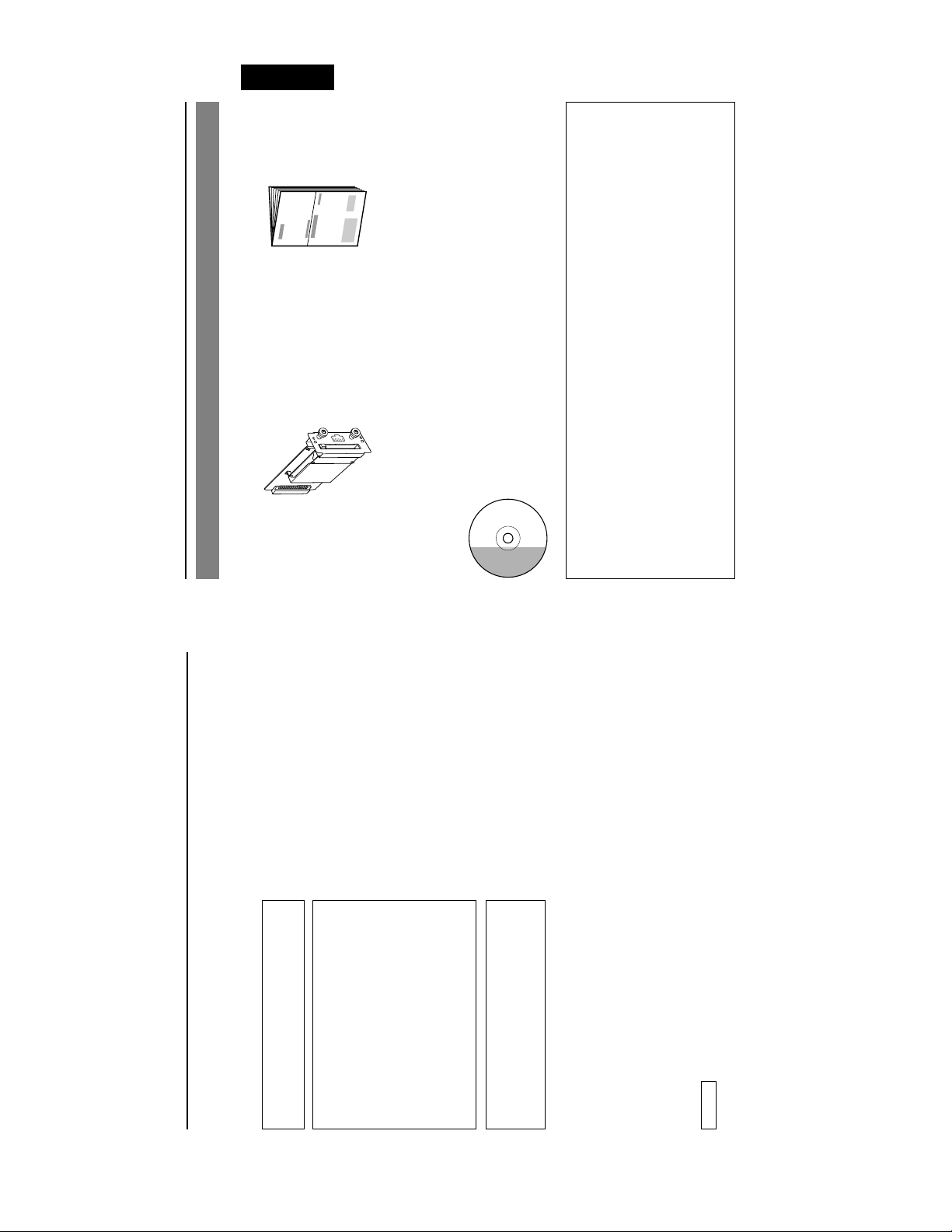
The following software and these Instructions are included on the provided
CD-ROM.
• PC Application Software
Reference guide for the Network Pack.
User's guide for the provided PC application software.
• Network Pack User’s Guide (pdf)
• PC Application Software User's Guide
E-3
Product Components
CD-ROM
Board for encoding/decoding video/audio
data by connecting to BR-DV6000.
Setting of the SA-DV6000 is performed on the menu screen of the BR-DV6000 VCR.
For details on the setting methods, please see the Network Pack User’s Guide (pdf) included
on the provided CD-ROM.
SA-DV6000 Users Guide (pdf)
When the Streamproducer program included on the provided CD-ROM is installed, the Net-
work Pack User’s Guide (pdf) is automatically installed on the PC and added to the Start
menu.
[Start/Programs/JVC/SA-DV6000U/User’s Guide]
The Adobe Acrobat Reader is required to view PDF files.
Safety Precautions
Thank you for purchasing this product.
(These instrustions are for SA-DV6000U)
Due to design modifications, data given in this
instruction book are subject to possible change
Before beginning to operate this unit, please read the instruction manual carefully in order
to make sure that the best possible performance is obtained.
without prior notice.
WARNING:
TO REDUCE THE RISK OF FIRE OR
ELECTRIC SHOCK, DO NOT EXPOSE
THIS APPLIANCE TO RAIN OR
MOISTURE.
AVERTISSEMENT:
POUR EVITER LES RISQUES
D’INCENDIE OU D’ELECTRO-CUTION,
POWER SYSTEM
Connection of POWER supply
The power for the network pack is supplied through
NE PAS EXPOSER L’APPAREIL A
L’HUMIDITE OU A LA PLUIE.
the VCR that is connected to the network pack.
This equipment is in conformity with the provisions and protection requirements of the correspond-
ing European Directives. This equipment is designed for professional video appliances and can be
used in the following environments:
• residential area (in houses) or rural area
• commercial and light industry; e.g. offices or theatres
• urban outdoors
In order to keep the best performance and furthermore for electromagnetic compatibility. Use the
PC Card which acquired a CE mark.
Caution
Where there are strong electromagnetic waves or magnetism, for example near a radio or TV
transmitter, transformer, motor, etc., the picture may be disturbed. In such case, please keep the
apparatus away from the sources of the disturbance.
E-2
Page 4

English
E-5
Precautions (cont’d)
• When using 1 VCR or 1 file.
Streamproducer Operating Environment
● Under the following conditions, the Streamproducer can be used in the required operating environment.
• When recording of the image is not performed.
• When switched distribution is not performed.
Hardware
Required operating environment
CPU Pentium 3 700 MHz
Memory 128 MB
Display XGA (1024 X 768)
compression) to 200 MB (low compression).
* 1 hour viewing time requires empty hard disk space equivalent to 25 MB (high
Hard disk * 50 MB for installation
* Other network environment for distribution if distribution is to be performed in other
Network * 1 LAN system for connecting the network pack
environment than that described above.
Software
OS Windows 2000 Professional, Windows XP Home Edition, Windows XP Professional
Please check the compatibility of the latest version of Windows Media from the JVC
website.
(English)
Others Streamproducer is an application applicable to Microsoft Windows Media.
make full use of the application’s functions.
Hardware
CPU Pentium 15 2.2 GHz or higher
Memory 512 MB or more
● When using multiple VCRs or files, the following operating environment is recommended in order to
Recommended Operation Environment
*1
Display SXGA (1280 X 1024) or more
*2
MEMO
Other operating environment demands are the same as the required operating environment demands.
*1
The described required operating environment and recommend operating environment are both
meant as guidelines to ensure optimal use of the application but are not meant as guarantee of
operation. Also, even if you use a computer that complies with the operating environment, optimal
use of the application may not be obtainable due to the configuration of your system.
Contents
Features ................................................................................................................................................. 4
Precautions ............................................................................................................................................ 4
What the SA-DV6000 can be used for ................................................................................................... 6
Names and Functions of Parts ............................................................................................................... 8
Europe: EA2903-162 (Revision C) (Name of manufacturer: Socket Communications, Inc)*1Asia: EA2906-194 (Revision C) (Name of manufacturer: Socket Communications, Inc)*1(The Revision designation is indicated in the upper right of the serial number label affixed to the
Features
input or tape playback in real-time, as well as to decode streaming data that has been stored on
CompactFlash memory card. Video data is converted to MPEG-4 and audio data is converted to
G726 or µlaw.
Installation Method ................................................................................................................................. 9
Check if Correctly Installed .................................................................................................................. 10
Specifications ....................................................................................................................................... 11
● By installing this product to the BR-DV6000, it is possible to encode the image/sound from VCR
enables real-time streaming.
● Connecting a network cable to the LAN connector or installing a LAN-card etc. in the PC card slot
● The real-time streaming data can be viewed by using Windows Media Player or Quick Time.
● Installing a Compact Flash card in the PC card slot enables real-time capturing.
Precautions
“Streamproducer” program included on the provided CD-ROM is installed on the PC.
● Network distribution of the video/audio file created by the SA-DV6000 is possible when the
cards, etc., into and from the VCR. Inserting or removing cards while the VCR’s power supply is
turned ON can result in corruption of the recorded sections of the card or damage to the card itself.
● Be sure to turn the VCR’s power supply OFF before the SA-DV6000 is attached to the VCR.
● Be sure to turn the VCR’s power supply OFF before inserting or removing CF (Compact Flash)
2003)
● The SA-DV6000 accepts the following cards for which operation has been confirmed: (As of June
US: EA2900-117 (Revision C) (Name of manufacturer: Socket Communications, Inc)
Operating voltage 3.3 V/5 V
Current consumption 250 mA
• Wired LAN-card
package.)
• Wireless LAN-card
SDCFB-16 ~ SDCFB-256 (Name of manufacturer: SanDisk)
TEW-201PC,TEW-202CF (Name of manufacturer: TRENDware)
WCF11 (Name of manufacturer: LINKSYS)
*1: Use PCMCIA card TYPE 1 or TYPE 2 adapter
*2: Use PCMCIA card TYPE 2 adapter
• CF (Compact Flash) card
Do not use other cards that those for which operation has been confirmed. Improper installation
may cause damage to the SA-DV6000.
For the latest operational check card, visit the website below or contact your JVC dealer.
http://www.jvc-victor.co.jp/english/pro/prodv/
registered trademarks of their respective owners.
In this document, symbols like ™, ®, ©, etc. have been omitted.
* The names of actual companies and products mentioned in this document may be the trademarks or
E-4
Page 5
REC
CAM
VTR
VTR CONTR
OL
REW
PLA
USE
FF
ST
OP
English
CAM
VTR CONTR
PLA
ST
OP
GE
POR
T SETUP
CONTR
OL
STREAM
CAPTURE
E-7
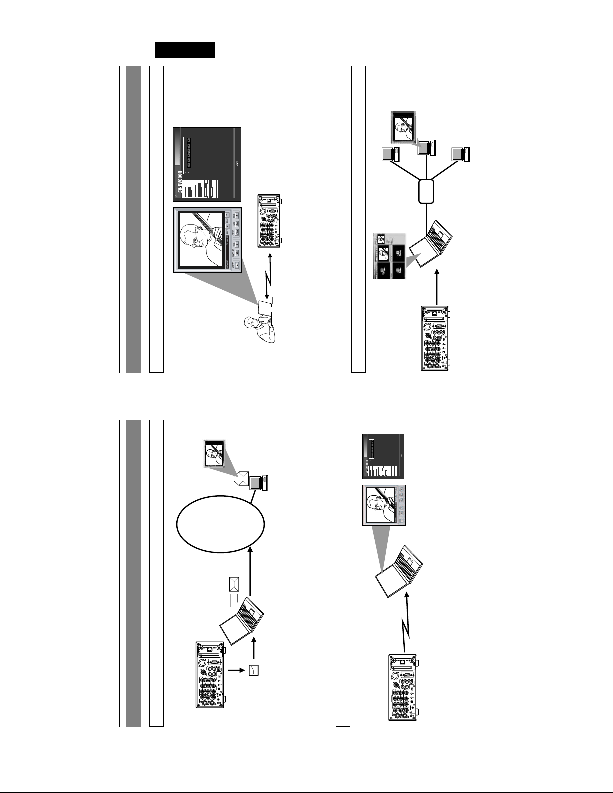
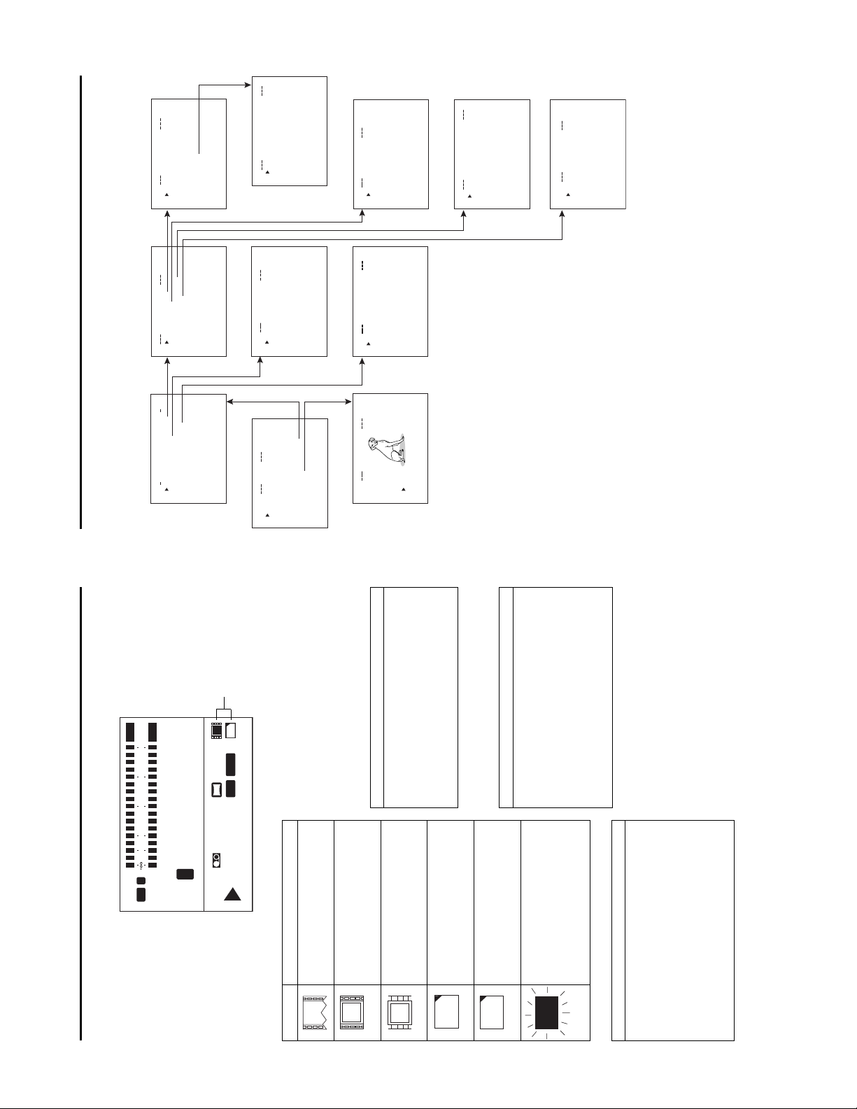
What the SA-DV6000 can be used for (cont’d)
Connecting a notebook computer for remote control with monitor
YPAUSE
OL
FF
OP
ST
VTR CONTR
CAM&VTR CONTROL
REW PLA
REC
VTR
CAM
OL
T SETUP
ENCODE
PARAMETERS
CAMERA&VTR
CONTR
POR
TOP PAGE
NETWORK
SETUP
(c) copyright 2002 VICTOR COMPANY OF JAPAN, LIMITED. All rights reserved
CAPTURE
STREAM
LAN
REMOTE1
IN
OUT
OUT
MONITOR
AUDIO
REMOTE2
CH 1/3 CH 2/4
OFF
TIMER
IN
OUT
REC PLAY
B-YR-Y
SERIAL
REMOTE
TIME CODE
IN OUT
IN OUT
COMPONENT
DV
IN/OUT
Y
SYNC IN
DC12V
VIDEO
IN
OUT
LINE
OUT
MONITOR
GND
SIGNAL
Y/C
VCR settings and VCR control can be performed using a notebook computer.
Operation method
Distributing VCR images on an intranet
☞ See “Streamcodec” in the Network Pack User’s Guide.
HUB
REMOTE2
IN
B-YR-Y
COMPONENT
VIDEO
IN
LINE
Y/C
LAN
IN
OUT
AUDIO
CH 1/3 CH 2/4
OUT
Y
OUT
Windows Media Server
REMOTE1
OUT
MONITOR
OFF
TIMER
REC PLAY
SERIAL
REMOTE
TIME CODE
IN OUT
IN OUT
DV
IN/OUT
SYNC IN
DC12V
OUT
MONITOR
GND
SIGNAL
to view the distributed VCR
3. Using Windows Media Player
redistribute the VCR images
2. Using Streamproducer to
to transfer the VCR
1. Using the SA-DV6000
XP
images on a PC
Operating environment
• Windows 98 (SE), Me, 2000,
transferred to the PC
Operating environment
• Windows 2000, XP
• Internet Explorer 5.01, 5.5 or 6.0
• JavaScript enabled
images to a PC
Operation method
☞ • See the User’s Guide to the “Streamproducer” software for network distribution.
• See “Network settings”, “LAN card” in the Network Pack User’s Guide (pdf)
YPAUSE
PLA
OL
FF
OP
ST
VTR CONTR
CAM&VTR CONTROL
REW
REC
VTR
CAM
TOP PAGE
NETWORK
(c) copyright 2002 VICTOR COMPANY OF JAPAN, LIMITED. All rights reserved
STREAM
CAPTURE
ENCODE
PARAMETERS
CAMERA&VTR
CONTROL
PORT SETUP
SETUP
viewing and/or filing the
VCR images on a PC
2. Using Streamcapture for
INTERNET
CF card as an e-mail attachment
2. Sending an image file stored on a
What the SA-DV6000 can be used for
Sending VCR video/audio by e-mail using CF (Compact Flash) card
LAN
REMOTE1
IN
OUT
OUT
MONITOR
AUDIO
REMOTE2
CH 1/3 CH 2/4
OFF
TIMER
IN
OUT
REC PLAY
B-YR-Y
SERIAL
REMOTE
TIME CODE
IN OUT
IN OUT
COMPONENT
DV
IN/OUT
Y
SYNC IN
DC12V
VIDEO
IN
OUT
LINE
OUT
MONITOR
GND
SIGNAL
Y/C
the VCR image on a CF card.
1. Using the SA-DV6000 for recording
Operation method
Viewing and filing VCR images on your PC using “Streamcapture”
☞ See Network Pack User’s Guide (pdf) “CF card recording”
LAN
REMOTE1
IN
OUT
OUT
MONITOR
AUDIO
REMOTE2
CH 1/3 CH 2/4
OFF
TIMER
IN
OUT
REC PLAY
B-YR-Y
SERIAL
REMOTE
TIME CODE
IN OUT
IN OUT
COMPONENT
DV
IN/OUT
Y
SYNC IN
DC12V
VIDEO
IN
OUT
LINE
OUT
MONITOR
GND
SIGNAL
Y/C
to transfer the VCR
images to a PC
1. Using the SA-DV6000
• See the User’s Guide to the “Streamproducer” software for network distribution.
Operation method
Operating environment
• Windows 2000, Windows XP Home Edition, Windows XP Professional
☞ • See “LAN card”, “Streamcapture” in the Network Pack User’s Guide (pdf)
• Internet Explorer 5.01, 5.5 or 6.0
• JavaScript enabled
E-6
Page 6
English
1
LOCAL
SELECT
DV
Y/C
LINE
(CPN)
PLAY PAUSE
OPERATE
Front Panel
MIX
AUDIO INPUT
CH-1/2
CH-3/4
REC
REW STOP FF
R
MONITOR OUTPUT REMOTE
MIX
A.DUB
EJECT
TC
COUNTER
UB
CTL L
PROFESSIONAL
BR-DV6000
BR-DV6000
SET SEARCH+
DISP
CH-1/3 CH-2/4
BLANK CUE UP
MENU RESET
HOLD
SEARCH–
PHONES REC LEVEL
MIC
Mini
of the optional board installation slot on
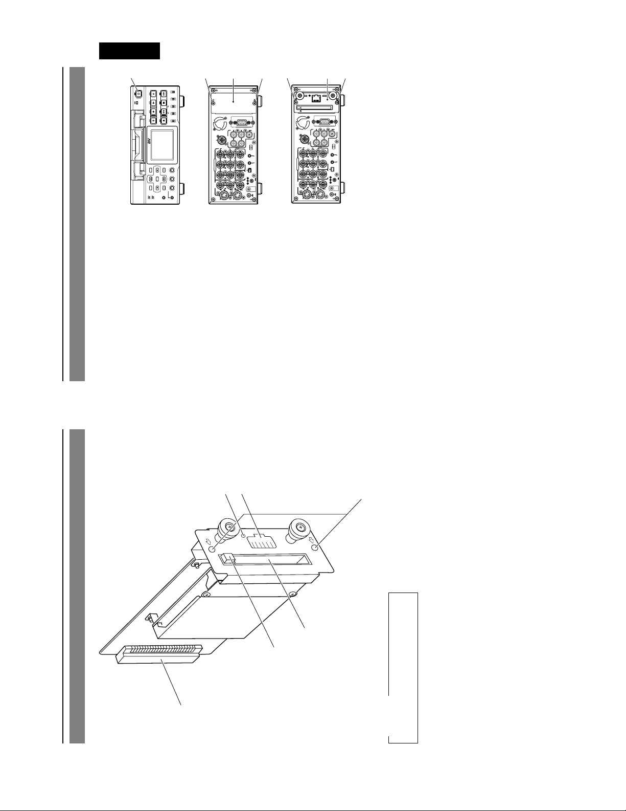
Installation Method
Follow the following procedure to install this
product to the BR-DV6000 DV Video Cassette
Recorder.
1 Switch off the VCR power.
the far right side of the rear panel.
2 Remove the two screws 2 from the cover
3 Remove the cover 3.
2
AUDIO
REMOTE2
CH 1/3 CH 2/4
IN
OUT
B-YR-Y
COMPONENT
Y
VIDEO
IN
OUT
LINE
Y/C
DV6000) along the guide rails, correctly
align the connectors and push in.
4 Insert the board of this product (SA-
main unit using the two screws 2 that
5 Fix the SA-DV6000 onto the BR-DV6000
235
REMOTE1
IN
OUT
TIME CODE
IN OUT
SYNC IN
OUT
MONITOR
Rear Panel
OUT
MONITOR
OFF
TIMER
REC PLAY
SERIAL
REMOTE
IN OUT
DV
IN/OUT
DC12V
GND
SIGNAL
REMOTE2
COMPONENT
VIDEO
LINE
were removed in step 2.
5
4
LAN
REMOTE1
IN
OUT
OUT
MONITOR
AUDIO
CH 1/3 CH 2/4
OFF
TIMER
IN
OUT
REC PLAY
B-YR-Y
SERIAL
REMOTE
TIME CODE
IN OUT
IN OUT
DV
IN/OUT
Y
SYNC IN
IN
Y/C
DC12V
OUT
OUT
MONITOR
GND
SIGNAL
E-9
5
6
3
Connects by pushing in the connector for
connecting to the VCR main unit.
4 Connector
Connect LAN cable here.
5 LAN Connector
Lights up when network is connected.
6 LINK LED
1
2
4
Names and Functions of Parts
CAUTION
Please don’t touch the metal parts other
than the panel.
Insert LAN card, CompactFlash card, etc.
here.
Push to eject the card.
Used to install this product to the rear
panel of the BR-DV6000 with screws.
1 PC Card Slot
2 EJECT Button
3 Mounting screw holes
E-8
Page 7
English
E-11
250 mA (main unit only)
---
—
Specifications
● Allowable storage temperature: –20°C to 60°C
● Power consumption: DC 12 V
● Power supply: Supplied from the BR-DV6000
PLAY PAUSE
OPERATE
REC
A.DUB
PROFESSIONAL
DISP
MENU RESET
Mini
SET SEARCH+
SEARCH–
● Allowable operating temperature: 0°C to 40°C
LOCAL
SELECT
DV
Y/C
LINE
(CPN)
MIX
AUDIO INPUT
CH-1/2
CH-3/4
REW STOP FF
R
MONITOR OUTPUT REMOTE
MIX
EJECT
TC
COUNTER
UB
CTL L
BR-DV6000
CH-1/3 CH-2/4
BLANK CUE UP
HOLD
PHONES REC LEVEL
MIC
● Mass: 190 g (main unit only)
1
TYPE 2 x 1 (Not compatible with Card Bus)
INSTRUCTIONS
Warranty Card (USA and Canada only)
● Allowable operating humidity: 30% to 80% RH
● Network interface: RJ-45 (category 5), 10 BASE-T/100 BASE-Tx
● PC card slot:
● Provided accessories CD-ROM
2
LAN
5
REMOTE1
IN
OUT
OUT
MONITOR
AUDIO
REMOTE2
CH 1/3 CH 2/4
OFF
TIMER
OUT
REC PLAY
SERIAL
REMOTE
TIME CODE
IN OUT
IN OUT
DV
IN/OUT
Y
SYNC IN
DC12V
OUT
OUT
MONITOR
GND
SIGNAL
COMPONENT
VIDEO
LINE
IN
B-YR-Y
IN
Y/C
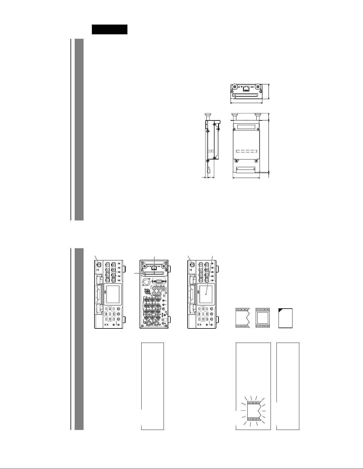
LAN
38
81
18
133.51.7
16 6
● External Dimensions (Unit: mm)
3
OPERATE
4
LOCAL
SELECT
DV
Y/C
LINE
(CPN)
PLAY PAUSE
MIX
AUDIO INPUT
CH-1/2
CH-3/4
REC
REW STOP FF
R
MONITOR OUTPUT REMOTE
MIX
A.DUB
EJECT
TC
COUNTER
UB
CTL L
PROFESSIONAL
BR-DV6000
SET SEARCH+
DISP
CH-1/3 CH-2/4
BLANK CUE UP
MENU RESET
HOLD
SEARCH–
PHONES REC LEVEL
MIC
Mini
68.5
(When power on)
: Blinks during initialization
internal LAN
: Effective for LAN Card or
Design and specifications are subject to change without notice.
: CompactFlash Card
e
F
C
Check if Correctly Installed
Follow the following procedure to check
whether this product has been correctly in-
stalled.
1 Tu rn OFF the power of the BR-DV6000.
Memo
product (SA-DV6000).
2 Insert a card into the Card Slot of this
The card status can be confirmed when
VCR.
the slot denotes the direction of the card.)
Insert the card with it’s surface facing the
LAN connector. (The < mark located near
3 Tu rn ON the power of the BR-DV6000
Make sure that the correct card status
4 Confirm the card status.
❈
indicator that matches the type of card you
inserted is displayed on the LCD of BR-
DV6000.
When the power is
turned on and the ini-
tialization process
takes place, the card
status indicators sho-
wn on the left will blink.
BR-DV6000 LCD screen is in enlarged
display mode.
NOTE
CAUTION
power off, and then press the Eject button
5 to eject the card.
To remove the card, turn the BR-DV6000’s
E-10
Page 8
User’s Guide
LST0154
SA-DV6000
NETWORK PACK
NETWORK PACK
SA-DV6000
LST0154
VICTOR COMPANY OF JAPAN, LIMITED
is a registered trademark in Japan, the U.S.A., the U.K. and many other countries.
is a registered trademark owned by VICTOR COMPANY OF JAPAN, LTD.
© 2003 VICTOR COMPANY OF JAPAN, LIMITED
Page 9

Introduction
The SA-DV6000 Network Pack is designed to enhance and complement the BR-DV6000 DV Video Cassette Recorder functionality.
By adding networking capabilities to the BR-DV6000, the SA-DV6000 allows users to connect to and stream video and audio from the
VTR in real-time, from anywhere in the world.
Viewers can connect using Windows Media Player, Quick Time Player, or the application software provided with SA-DV6000.
All while recording the highest quality video to DV tape.
It is also possible to operate the BR-DV6000 (PLAY, STOP, REC, etc.) via a network.
The SA-DV6000 allows real-time streaming of video from BR-DV6000’s Video inputs as well as from pre-recorded DV and miniDV
tapes.
With bit rates ranging from 56 to 512kb/s, the SA-DV6000 supports many connection types, from MODEMS and ISDN to broadband.
When using the trigger mode function of this unit, video can be recorded to a client PC on a network.
The SA-DV6000 even allows the BR-DV6000 VTR to become a publishing point for a media server.
When used with a CompactFlash memory card, the SA-DV6000 features can enhance productivity of any studio.
At the same time as recording to a DV tape, scene file (streaming data) and clip list (CSV file) that contains information such as the
starting and ending points, time code, etc. are automatically recorded to the Compact Flash Memory.
This log file is readable by database, spreadsheet, and text editing programs, and can be use with non-linear editing systems.
The log and scene files are small enough to send anywhere, instantly through email.
Characters and symbols used in this instruction book
☞ Reference page or item
tered trademarks of these companies.
Memo Reference such as restrictions of features, etc.
Using the provided application (CFViewer), you can view thumbnail images of all recorded scenes, and even perform basic assemble
editing for review.
In addition, the CF card prevents SA-DV6000 obsolescence.
Caution Cautionary notes concering operation of the unit
As improvements are made, just download the files from our Web Site onto a CF card, and update your SA-DV6000.
Symbols like ™, ©, ®, etc., are not used in these instructions.
* In general, the names of products manufactured by other companies and mentioned in these instructions are trademarks or regis-
3
Inserting/removing CF memory card/LAN card ............................................................................................................................... 4
Using LAN terminal .......................................................................................................................................................................... 5
LCD screen ...................................................................................................................................................................................... 6
Introduction ...................................................................................................................................................... 3
Basic
Contents
Menu screen structure ..................................................................................................................................................................... 7
NETWORK PACK menu screen items .............................................................................................................................................. 8
Setting the NETWORK PACK menu screen ................................................................................................................................... 10
Setting network parameters ........................................................................................................................................................... 11
NETWORK settings menu screen item........................................................................................................................................... 12
Menu Settings
Setting user names and passwords ............................................................................................................................................... 14
Inputting character data for network settings ................................................................................................................................ 15
Restoring factory default ................................................................................................................................................................ 16
About video/audio encoding ..........................................................................................................................................................17
Encoding parameter settings .........................................................................................................................................................18
Encording
LAN connection
2
Wired Connection, single VTR to single Client PC .................................................................................................................... 20
Wired Connection, Multiple VTR to single Client PC ................................................................................................................. 21
Wired Connection, Multiple Client PC to a single VTR .............................................................................................................. 22
Wireless Connection, single VTR to single Client PC ................................................................................................................ 24
Wireless Connection, Multiple VTR to single Client PC ............................................................................................................. 25
About LAN Connection .................................................................................................................................................................. 19
Wired LAN ...................................................................................................................................................................................... 20
Wireless Connection, Multiple Client PC to a single VTR .......................................................................................................... 26
Wireless LAN ..................................................................................................................................................................................23
Proxy Settings................................................................................................................................................................................. 27
Streaming and capturing Video ..................................................................................................................................................... 28
Recording to DV tape and Client PC Simultaneously .................................................................................................................... 29
Recording to DV tape and Client PC Independently ..................................................................................................................... 30
Streaming and capturing from a Pre-Recorded DV tape ............................................................................................................... 31
Preparing for CF card recording ....................................................................................................................................................32
Recording to DV tape and CF card Simultaneously ...................................................................................................................... 33
Recording to DV tape and CF card Independently ....................................................................................................................... 34
Recording from a Pre-Recorded DV tape to a CF card .................................................................................................................35
Specifying the range of a DV tape and recording to CF memory card ......................................................................................... 36
Deleting all clip files on a CF memory card ................................................................................................................................... 37
Selecting playback mode of movie clip ......................................................................................................................................... 38
Playing back a CF memory card .................................................................................................................................................... 39
Selecting another clip while playing a clip ..................................................................................................................................... 41
Protecting a clip file on a CF memory card .................................................................................................................................... 42
Delecting a clip file on a CF memory card ..................................................................................................................................... 43
Playing back CF memory card clips on your PC ........................................................................................................................... 44
Using LAN card/LAN terminal
Recording on a CF card
Movie Clip
Transferring a clip on a CF memory to a server ............................................................................................................................. 45
FTP client setup ......................................................................................................................................................................... 50
FTP Server Account / ESS-ID / WEP key / LEAP Server Account Setup ................................................................................... 51
PORT SETUP page......................................................................................................................................................................... 52
Transferring multiple clips on a CF memory card to a server ........................................................................................................46
Controlling the BR-DV6000/SA-DV6000 via a network................................................................................................................... 47
VTR control .....................................................................................................................................................................................53
NETWORK SETUP page ................................................................................................................................................................ 49
Network remote control
ENCODE PARAMETERS ................................................................................................................................................................ 54
STREAMCAPTURE(Playing back Video / audio using a PC and saving to file)............................................................................. 56
Transferring clips on a CF memory card to a server...................................................................................................................... 60
TOP PAGE can be customized ...................................................................................................................................................... 61
Connecting Windows Media Player ............................................................................................................................................... 62
Connecting QuickTime Player ........................................................................................................................................................ 63
About updating the network pack ..................................................................................................................................................64
Troubleshooting .............................................................................................................................................................................. 65
Checking communication / connection .......................................................................................................................................... 67
Ter minology .................................................................................................................................................................................... 68
About IP address/proxy server....................................................................................................................................................... 70
Others
Page 10
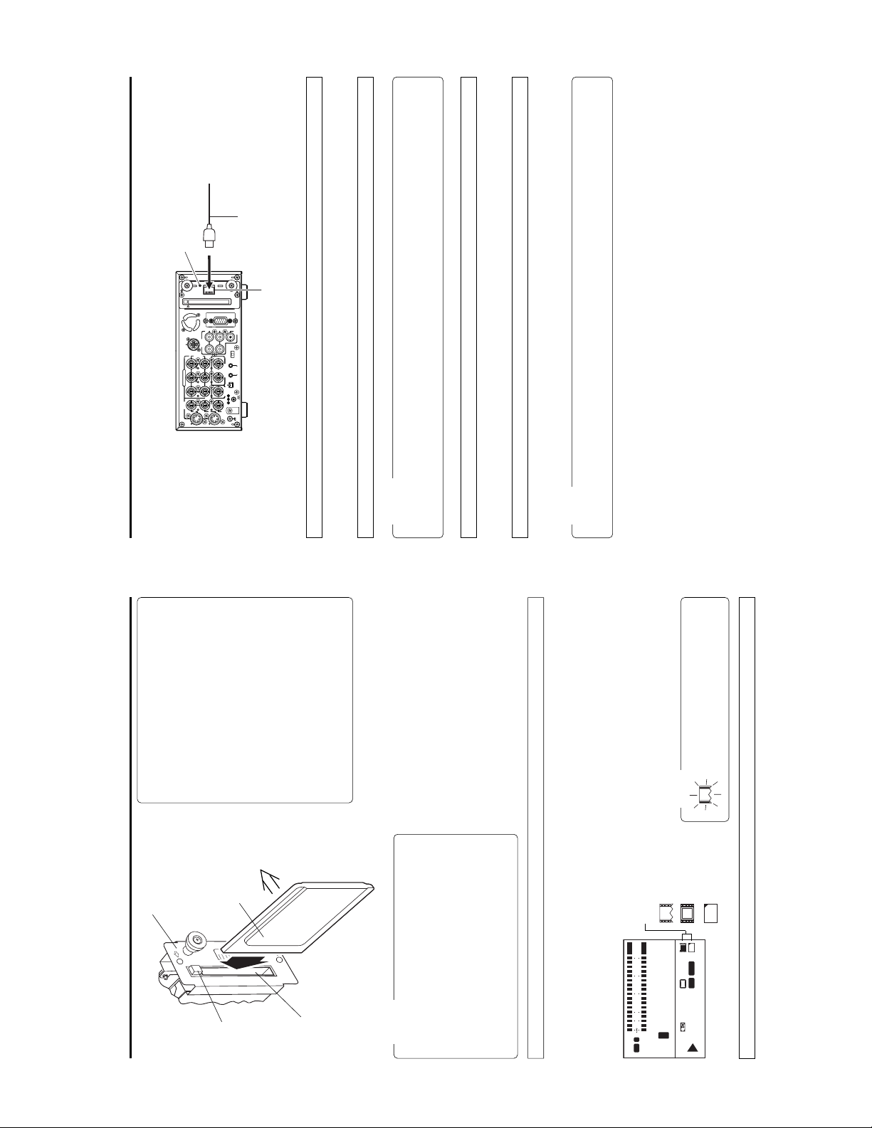
Link LED
LAN cable
LAN
IN
OUT
AUDIO
REMOTE2
CH 1/3 CH 2/4
IN
OUT
B-YR-Y
TIME CODE
IN OUT
COMPONENT
Y
SYNC IN
VIDEO
IN
OUT
LINE
OUT
MONITOR
Y/C
Other than the use of a LAN card, this unit is also equipped with a LAN terminal for LAN connection.
Basic Using LAN terminal
*1
*1
*1
LAN terminal
REMOTE1
OUT
MONITOR
OFF
TIMER
REC PLAY
SERIAL
REMOTE
IN OUT
DV
IN/OUT
DC12V
GND
SIGNAL
LAN cable types
● When connecting directly to a PC, use a 10/100 BASE-T cross cable.
● When connecting to a network hub, use a 10/100 BASE-T straight cable.
*1
*2
Caution
Connecting to the LAN terminal
● Do not remove the LAN cable when the Link LED is on. For a short time, menus cannot be opened.
● Do not connect/disconnect the LAN cable when recording to a CF memory card.
Completely insert the connector of the LAN cable.
● Do not mount a LAN card when the Link LED is on.
Link LED
When using both LAN card and LAN terminal
The Link LED will light when connected to a network using the LAN terminal.
When mounted with a LAN card, the Link LED will not light.
Memo
When mounted with a CF memory card, the following can be performed:
When mounted with a LAN card, the LAN card will be given priority for LAN connection. In this case, communication via the LAN
terminal is not possible.
● Transferring of a clip recorded on a CF memory card to a server via the LAN terminal.
5
Communications, Inc)
Communications, Inc)
Communications, Inc)
Europe: EA2903-162 (Revision C) (Name of manufacturer: Socket
Asia: EA2906-194 (Revision C) (Name of manufacturer: Socket
* Revision indicated on the upper right of package production label.
TEW-201PC
TEW-202CF
US: EA2900-117 (Revision C) (Name of manufacturer: Socket
been confirmed: (As of June 2003)
Operating voltage 3.3 V / 5 V
Current consumption Max. 250 mA
●Wired LAN-card
● TheSA-DV6000 accepts the following cards for which operation has
TEW-PC16 (firmware version 0.8.3 or later) (Name of manufacturer:
●Wireless LAN-card
Surface
CF memory card or
LAN card
SA-DV6000
Basic Inserting/removing CF memory card/LAN card
EJECT button
(Name of manufacture: Cisco Systems)
FCCID: LDK102040
TRENDware)
WCF11 (Name of manufacturer: LINKSYS)
AIR-PCM350
*2: Use PCMCIA card TYPE 2 adapter
●CF (Compact Flash) card
SDCFB-16 ~ SDCFB-256 (Name of manufacturer: SanDisk)
*1: Use PCMCIA card TYPE 1 or TYPE 2 adapter
Card slot
For the latest operational check card, visit the website
below or contact your JVC dealer.
http://www.jvc-victor.co.jp/english/pro/prodv/
Caution
removing a CF memory card/LAN card. Inserting/removing
a card with the unit power on may damage the data storage
section of the CF memory card or the card itself.
DV6000 on. Recorded section on the CF Memory Card or
the CF Memory Card itself may be damaged as a result.
● Make sure the power of BR-DV6000 is off when inserting/
● Do not remove the power cable with the power of the BR-
than 48 hours.
● Do not use the wireless LAN card continuously for more
the LCD screen. (☞ page 6)
Enlarged display mode.
● Card status according to the inserted card type is displayed on
● The card status is displayed when setting the LCD screen to the
initialization
: Flashes during
Card status display
F
dB010203040
OVER
OVER
10
S
34
M
34
CH1
H
12
C
T
L
NDF
48k
FREE
CH2
LCD screen
Turn off the BR-DV6000 power.2.Insert a card into the SA-DV6000 card slot.
1.
Turn on the BR-DV6000 power.
3.
Inserting card
When turning the power on, the card status
display shown on left will flash during initial-
ization.
Memo
4
in LAN enabled
: LAN card or built-
: CF memory card
F
e
C
e
‰
CF
VA
SYNC
W
Y/C
min
SP222
01/02/03
01:23:45 INS
AM
PLAY
Turn off the BR-DV6000 power.2.Press the EJECT button of SA-DV6000 and remove the card.
Removing card
1.
Page 11
menu screen
. NETWORK .SETUP .
NETWORK SETUP
N
MA I
WOETNRK
menu screen
NETWORK MAIN
KPACKCONFIG
R
O
menu screen
TW
E
N
NETWORK PACK CONFIG
Menu settings Menu screen structure
When attaching Network Pack SA-DV6000 to BR-DV6000 DV Video cassette recorder, NETWORK PACK CONFIG menu and MOVIE
CLIP menu are added to the BR-DV6000 TOP MENU screen.
(These menus will not appear during initialization when the unit is first turned on.)
NNNNNNN
NNNNNNNNNNNN
ASK . . .
.......
IP. ADDRESS . . ........
SUBNET . M NNNNNNNNNNNNN
HOST . NAME . . ....
DHCP . NNNNN NOFFNNN
SETUP. .
SETUP. .
NETWORKNSETUP. .
PORT.
WIRELESS. LAN. SETUP. .
SERVER. S
.
TRI G.
..
N
MA I
SETUP. .
KSETUP.
R
TWO
VIE CLIP. SETUP
E
O
ENCODE .
N
M
MPE G. REC .........
.N
NNNNNNNNNNNNNNN
NAME. S ERVER .
GAT EWAY . . .N
PAGE. BACK..NNN
. CANCEL
ACK ...
B
GE .
A
P
MENU . RESET
NNNNNNNNNNNNNNN
.N
FTPECl i ent..
PAGE. BACK ..N
*2
)
r
e
View
F
C
(
)
8
r
e
Pund
M
W
(
*1
TC 0 0:00: 000.0
menu screen
FTP CLIENT SETUP
TC 0 0:00: 000.0TC 0 0:00: 000.0
menu screen
ENCODE SETUP
TOP MENU screen
N
N
N
UP
S
TORPET
PORT SETUP menu screen
menu screen
. MOV I E . CL IP SETUP
MOVIE CLIP SETUP
L
IEOVMCIP
(☞ page 39)
MOVIE CLIP list screen
..
....
..
...
..
..
..
RTSP. for Streamproducer
PAGE BACK.....NNNNN. .. NNNN
HTTP. fo r Media player
STG. BACKNNNNNNNNNNNfor WMP N
HTTP. fo rWEB Browser
PAG. BACK. NNNNNNNNNNNNNNNNN
RTSP. for QuickTime
CANCEL
FORMAT ...NNNNNNNNN. . .
FILE. SEND............
PAGE. BACK ..................
DELETE .ALLNNNNNNNNNNNCANCE L
REPEAT PLAY ..........REPEAT
CAPTU RE. . ..................
09 0 0:00:
09 3 0:25:
10 1 0:55:
11 0 0:00:
.
.
.
.
0asf WR/
0asf WR/
0asf WR/
0asf WR/
10 25/02/
10 25/02/
10 25/02/
10 25/02/
00 1
00 2
00 3
00 4
mcmcmc
mc
TC 0 0:00: 000. 0
menu screen
WIRELESS LAN SETUP
TC 0 0:00: 000.0
CK
A
AGE B
P
clip files in the CF memory card
* Example of display when there are
TC 0 0:00: 000. 0
LIENT S ETUP
NAME. .
FTP C
H
PAGE. BACK
PASSWORD . .
PASS I VE DE ONMO
USER
DIRECTORY..
MAC I N E N AM E ..
240.
x
TC 0 0:00: 000.0
TYPE
. ENCODE.SE TUP .
FRI
FRAME. SIZE NNNNNNNN320
PAG. BAC NNNNNNNNNNNNNNNNNNEK
MAX . F RAME. RAT ENNNNNMIDNNNNN
BIT. RATE. NNNNNNNNNN384kb/s..
PRE LTE NNNNNNNNNAD1 NNNNN
STREAM. NNNNNNNNfor WM P NN
..
MENU
KPACKCONFIG
R
E
IT
TWO
X
E
TC / UB /C LOCK . .
SYST EM . .
E
VIDEO. .
REMOTE . .
AUD I O . .
DISPLAY SET . .
N
MOV I C L I P. .
.
CEL
10C
2CHWEP .KEY .............. ..
2CHPAGE. BACK ............ ..
CANCEL
OFFLEAP ................. ..
SETUP.WI RELESS .LAN .
.......REPEAT
. NNNN . . .
Primary ESS . ID.
Secondary ES S I D
AD .HOC . MOD E NNNNNNNNOF F
TC 0 0:00: 000. 0
Country ESSID.......USAEAT
CH ................... H .
SERVER SETUP
Player.
with CFViewer (provided application) is created. (During the TRIG
mode)
*1 Indicates the currently compatible version of Windows Media
*2 When (CFViewer) is displayed, a clip list (CSV file) that can be used
SETUP
. SERVERN
menu screen
LEAP . USER .NAME . . ....115200.
SETUP .ON .WE B ........OFF ....
00.
LEAP . PASS .WO RD . .....1152
0.
HTTP .US ER. NAME . . ....11520
HTTP . PASS .WOR D . .....1152
FTP. USER . NAME. . ....11520
. 11520
FTP. PASS .WO R D . ....
PAGE. BACK ...
TC 0 0:00: 000. 0
7
Card status display
dB010203040
OVER
CH1
L
48k
OVER
CH2
F
10
S
34
M
34
H
12
C
T
NDF
FREE
e
CF
SYNC
W
Y/C
min
SP222
01/02/03
PLAY
‰
VA
\ CF Memory card warning display
Displays CF memory card status and system errors.
* For details concerning warning displays, see page 65.
01:23:45 INS
AM
When inputting the 44.1kHz sampling audio signal
Description
Flashing display during initialization (after
power on).
LAN card is inserted in the Network Pack, or
built-in LAN is enabled.
Display
Basic LCD screen
Information from Network Pack SA-DV6000 is displayed on the BR-DV6000 LCD screen.
Card status and warnings will be displayed when setting the LCD screen to the Enlarged display mode.
\ Card status displays
e
(White display)
About restrictions of BR-DV6000
This unit is not compatible with audio sampling frequency of
44.1kHz. When playing back a tape recorded with audio of
44.1kHz on BR-DV6000 or when inputting audio in the 44.1kHz
mode into the DV terminal, the audio will be processed as
muted sound. However,the video will be processed as nor-
mal.
Video/audio data is being sent via LAN card.
CF memory card is inserted in Network Pack.
(Red display)
F
C
(White display)
e
Only BR-DV6000 marked with (A) at the end of the model
name on the Rating Label is compatible with this unit (SA-
DV6000).
If a line appears between the time code and level meter on
the LCD screen (Enlarged display mode) while SA-DV6000 is
mounted on BR-DV6000, the BR-DV6000 in use is not com-
CF memory card is being recorded with data.
Card is inserted in Network Pack but trans-
mission is not available.
There is possibility of unit malfunction.
Contact your nearest JVC dealer.
F
C
(Red display)
X
Flashing display
patible with SA-DV6000 and requires an upgrade.
For details, consult your JVC dealer.
6
Receiving Level Indicator of Wireless LAN
If you are using wireless LAN card that can detect receiving
level, receiving level indicator is shown next to the card status
information on LCD of the BR-DV6000. The indicator shows
value from 5 to 0, 5 means maximum level and 0 means mini-
mum level. (The indicator is for reference. The value does not
guarantee communication.)
Some cards may not be able to accurately display the strength
of the signals of the wireless LAN if communication is abruptly
interrupted.
Page 12
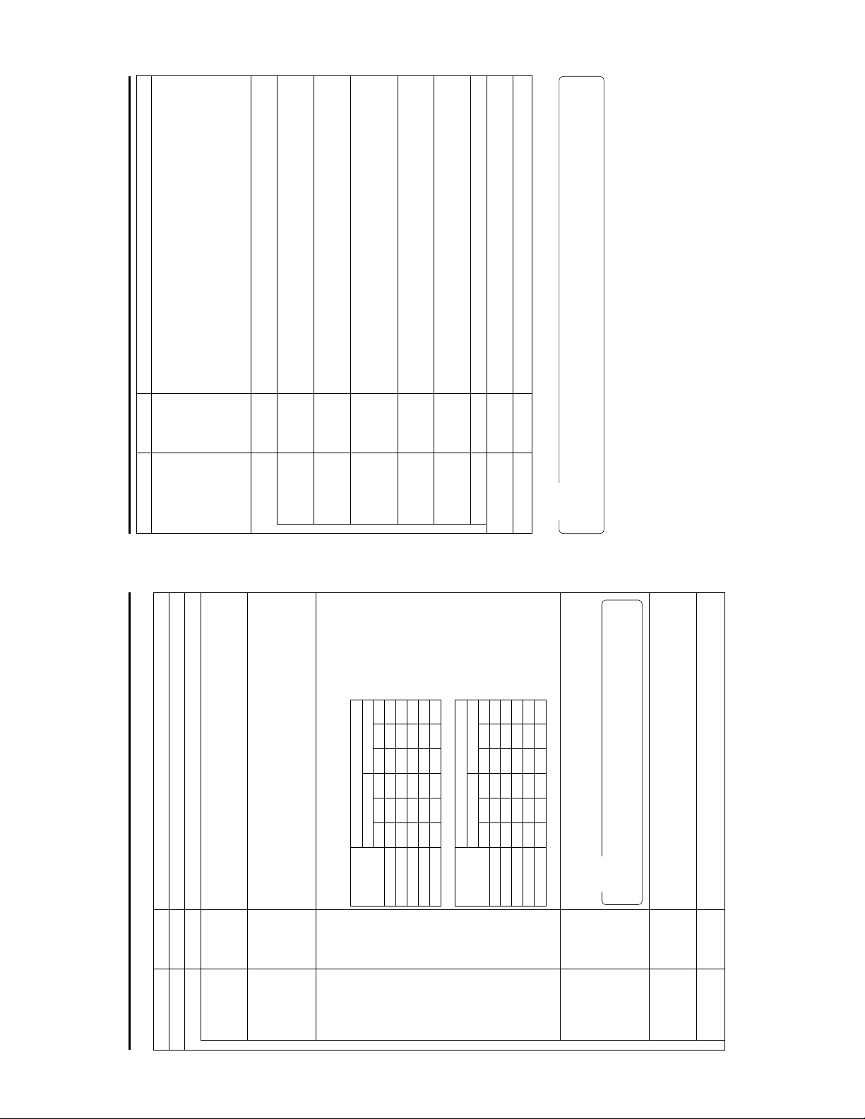
Description
the same time. Use this setting when simultaneously recording to a DV tape.
card/LAN terminal only. Operation starts when pressing the SET button of BR-
DV6000.
data to a PC from the LAN card/LAN terminal is possible.
Selects the operation method for recording video data to a CF memory card or sending
data to a Client PC from a LAN card/LAN terminal.
TRIG: Operation will start when pressing the REC and PLAY buttons of BD-DV6000 at
SPLIT: Use this setting when recording or transferring with CF memory card or LAN
OFF: Recording will not be made to the CF Memory Card. Transmission of streaming
Displays the menu screen for CF memory card related settings such as formatting or
deleting all recorded clip files.
Selecting EXECUTE and pressing the SET button deletes all clip files on the CF memory
card.
Protected clip files are not deleted.
Selecting EXECUTE and pressing the SET button starts formatting the card.
All recorded clips are erased.
Caution: All protected clip files and other files will also be erased.
Playback is performed from the specified clip file to the latest clip file and pauses at the
specified clip file.
Setting
SPLIT
OFF
TRIG
Item
MPEG REC
Menu settings NETWORK PACK menu screen items
MOVIE CLIP SETUP
EXECUTE
CANCEL
DELETE ALL
EXECUTE
CANCEL
FORMAT
OFF
PLAY MODE
page 36)
☞
page 46)
☞
Specified clip file is played backed 3 times.
Playback is performed 3 times from the specified clip file to the latest clip file.
When pressing the SET button, the FILE CAPTURE screen appears.
Recording can be made to the CF memory card by specifying the range of the DV
cassette tape in the FILE CAPTURE screen settings. (
When pressing the SET button, the clip file specified from a CF memory card can be
transferred to a specified server via FTP.
Transfer will be performed via the LAN terminal. (
Pressing the SET button returns to the NETWORK PACK CONFIG menu screen.
Selecting EXECUTE and pressing the SET button returns NETWORK PACK CONFIG
menu screen settings to the original factory settings.
Pressing the SET button SEARCH– button returns to the TOP MENU screen.
CF REC: PUSH ‘SET’
REPEAT 1
REPEAT
CAPTURE
FILE SEND
EXECUTE
CANCEL
PAGE BACK
MENU RESET
PAGE BACK
Memo
When setting MPEG REC to SPLIT, the following will appear in the NETWORK PACK CONFIG menu screen.
9
page 11)
☞
Description
✩ indicates items that can also be set from a PC. (☞ page 54)
Displays menu screen for network related settings. (
Displays menu screen for setting video and audio compressions.
Sets the video compression size.
Setting
Item
indicates default factory setting.
Menu settings NETWORK PACK menu screen items
320 × 240
FRAME SIZE
NETWORK MAIN SETUP
ENCODE SETUP
(1/4 image size of SIF.)
Sets streaming speed (bps).
320 × 240: Sets the image size to 320 × 240 pixels. (SIF)
160 × 120: Sets the image size to 160 × 120 pixels. (QSIF)
160 × 120
56K
BIT RATE
✩
✩
56K: MPEG4 24 kbps (G726 16 kbps for WMP) (µlaw 64kbps for QT)
128K: MPEG4 104 kbps (G726 16 kbps for WMP) (µlaw 64kbps for QT)
256K: MPEG4 224 kbps (G726 32 kbps for WMP) (µlaw 64kbps for QT)
384K: MPEG4 352 kbps (G726 32 kbps for WMP) (µlaw 64kbps for QT)
512K: MPEG4 472 kbps (G726 40 kbps for WMP) (µlaw 64kbps for QT)
128K
256K
512K
384K
FRAME SIZE
MAX MID MIN MAX MID MIN
512K 15 10 7.5 30 15 10
384K 15 10 7.5 30 15 10
Sets the frame rate per second. The maximum tranmitted frames per second varies
MAX
MAX FRAME
BIT RATE 320 × 240 160 × 120
depending on the FRAME SIZE and BIT RATE settings as shown below:
\ NTSC signal
MIN
MID
RATE
✩
256K 15 7.5 5 30 15 7.5
FRAME SIZE
MAX MID MIN MAX MID MIN
56K 3 1 1 10 7.5 5
128K 7.5 5 3 15 10 7.5
BIT RATE 320 × 240 160 × 120
\ PAL signal
512K 12.5 5 5 25 12.5 12.5
OVER
→
8
56K 1 1 1 12.5 5 5
384K 12.5 5 5 25 12.5 5
256K 12.5 5 5 25 12.5 5
128K 5 5 1 12.5 12.5 5
* The frame rates shown in the table are not guaranteed values.
Memo
• No sound will be heard when playing back using QuickTime while in the WMP mode.
• No sound will be heard when playing back using Media Player while in the QT mode.
Sets the player for stream playback.
for WMP : Media Player, Provided application
for QT : Quick Time
for QT
for WMP
STREAM TYPE
✩
• Set to WMP mode when recording to CF memory card.
AD1 is effective for video with many still images and AD2 is effective for video with
motion.
AD2
AD1
PRE FILTER
Pressing the SET button or SEARCH– button returns to the NETWORK PACK CONFIG
menu screen.
PAGE BACK
Page 13
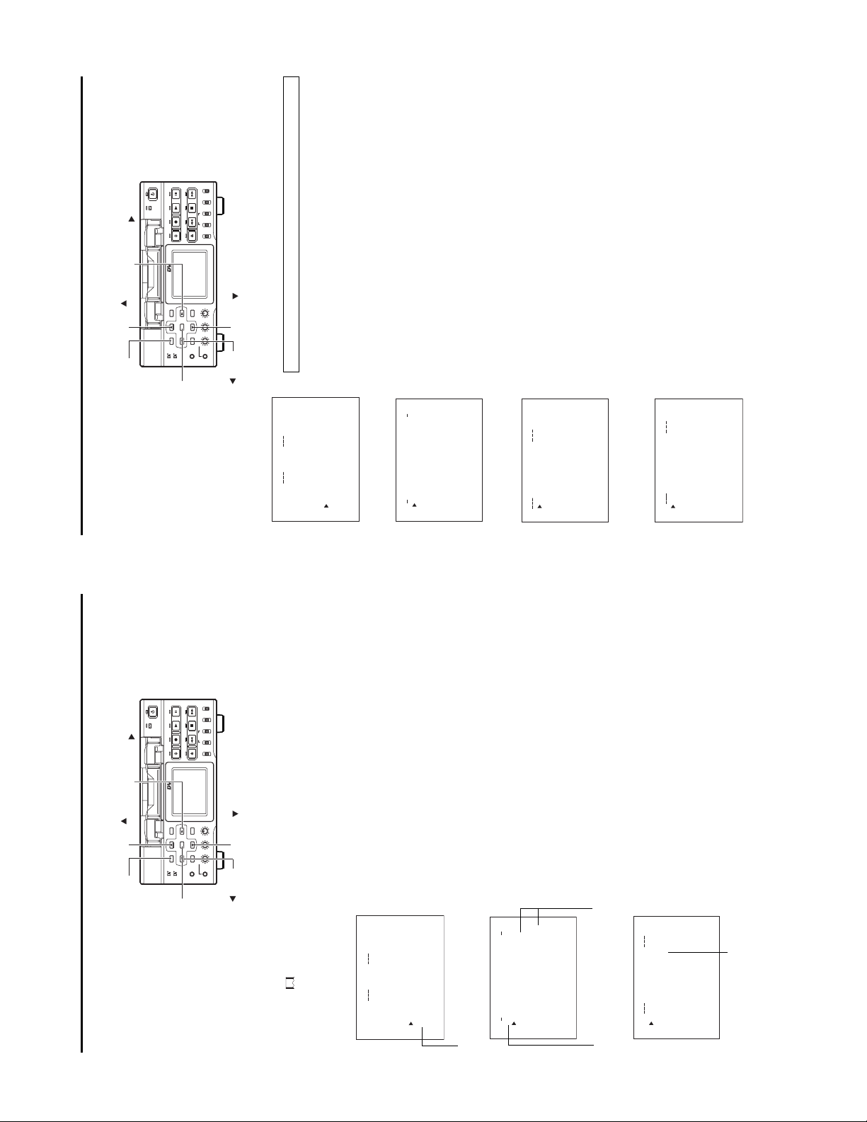
SEARCH+ ( ) button
DISP ( ) button
LOCAL
SELECT
DV
Y/C
LINE
PROFESSIONAL
(CPN)
MIX
AUDIO INPUT
CH-1/2
CH-3/4
REW STOP FF
R
MONITOR OUTPUT REMOTE
MIX
EJECT
TC
COUNTER
UB
CTL L
BR-DV6000
PLAY PAUSE
OPERATE
REC
A.DUB
11
SET SEARCH+
DISP
BLANK CUE UP
MENU RESET
HOLD
SEARCH–
MIC
Mini
PHONES REC LEVEL
BLANK ( ) button
CH-1/3 CH-2/4
Turn on the BR-DV6000 power.2.Check to see that the card status display has changed from a flashing to constant
display.3.Press the MENU button to display the TOP MENU screen.
Press the DISP (6) or the BLANK (7) button, move the cursor (t) to NETWORK
PACK CONFIG and press SET button or SEARCH+ (t) button.
Press the DISP (6) or the BLANK (7) button, move the cursor (t) to NETWORK
● The NETWORK PACK CONFIG menu screen appears.
4.
5.
\ Settings are made by viewing the LCD screen or video monitor.
Display the NETWORK SETUP menu screen
1.
NETWORK SETUP
PORT SETUP
WIRELESS LAN SETUP
The NETWORK MAIN menu screen is structured by four screens.
MAIN SETUP and press the SET button or SEARCH+ (t) button.
● The NETWORK MAIN menu screen will appear.
SERVER SETUP
Press the DISP (6) or the BLANK (7) button, move the cursor (t) to SETUP and
6.
press the SET button or SEARCH+ (t) button.
Items with “..” at the end of the name are set in the INPUT screen.
● The selected SETUP screen appears.
To return to the NETWORK MAIN SETUP menu screen, select PAGE BACK and
press the SET button or, press the SEARCH– (8) button.8.To return to the normal screen after completing setting, perform one of the follow-
7.
MENU screen and press the SET button.
ing operations.
● Press the MENU button
● Select PAGE BACK to return to the TOP MENU screen. Select EXIT in the TOP
MENU button
SET button
SEARCH– ( ) button
TOP MENU screen
Menu settings Setting network parameters
When using a LAN card or LAN terminal, network related settings for SA-DV6000 are made using NETWORK MAIN SETUP of the
NETWORK PACK CONFIG menu. Settings will be stored in the SA-DV6000 memory even when turning the power off.
LOCAL
SELECT
DV
Y/C
LINE
PLAY PAUSE
OPERATE
REC
A.DUB
(CPN)
MIX
AUDIO INPUT
CH-1/2
CH-3/4
REW STOP FF
R
MONITOR OUTPUT REMOTE
MIX
EJECT
TC
COUNTER
UB
CTL L
..
MENU
.
KPACKCONFIG
R
E
T
I
TWO
E
X
TC / UB / CL OCK . .
VIDEO. .
SYST EM . .
E
REMOTE .
AUD I O . .
DISPLAY SET. .
N
MOV I C L I P . .
IG
F
ON
C
P
ORTWENKACK
menu screen
NETWORK PACK CONFIG
)
r
e
ACNLE
RGI
C
T
View
F
TSE PU..
C
TC 00 :0 0 : 000 . 0
(
TSE P . .U
)
8
IMA N
P
TSE P . .U
r
e
LI
CK
C
A
Pund
M
W
NET WOR K
MPE G R EC
PAGE B
(
ENCODE
MOV I E
MEN U R E S ET
..
P
U
ET
N
..
S
..
P
P
MA I
U
N
..
U
A
ET
P
L
K
K
ET
S
U
C
S
S
A
ET
WOETNR
ES
S
L
WOETNRK
PAGE B
SERVER
PORT
WIRE
NETWORK MAIN menu screen
TC 00 :0 0 : 000 . 0
P
U
S
WOETNRKET
HOS T N AME . .
NETWORK SETUP menu screen
FOF
..NET M SA
..
K
ESS
R
IP ADD
DHC P
SUB
TC 00 :0 0 : 000. 0
..
..
R
ntFTP Cl
K
VE
..GATEWA
e
R
C
i
A
Y
S
PAGE B
NAME E
SEARCH+ ( ) button
PROFESSIONAL
BR-DV6000
DISP ( ) button
page 11)
☞
SET SEARCH+
DISP
BLANK CUE UP
MENU RESET
HOLD
SEARCH–
MIC
Mini
PHONES REC LEVEL
BLANK ( ) button
CH-1/3 CH-2/4
setting can be changed. Set the item according to step 6.
Turn on the BR-DV6000 power.2.Press the MENU button. The TOP MENU screen appears.
Press the DISP (6) or the BLANK (7) button, move the cursor (t) to NETWORK
1.
\ Settings are made by viewing the LCD screen or video monitor.
3.
PACK CONFIG and press the SET button or SEARCH+ (t) button.
● The NETWORK PACK CONFIG menu screen appears.
to set and press the SET button.
Select the item to set.
Press the DISP (6) or the BLANK (7) button, move the cursor to the desired item
● The selected menu screen appears.
● When selecting MPEG REC or MENU RESET, the setting area flashes and the
4.
appears. (
Select an item within the menu screen.
Press the DISP (6) or the BLANK (7) button, move the cursor (t) to the desired
● When selecting NETWORK MAIN SETUP, the network related setting screen
item to set and press the SET button.
● The setting area flashes and the setting can be changed.
5.
SET button.
Change the setting.
Press the DISP (6) or the BLANK (7) button to change the setting and press the
6.
press the SET button or SEARCH– (8) button.
Return to the TOP MENU screen.
Press the DISP (6) or the BLANK (7), move the cursor (t) to PAGE BACK and
● Flashing of the setting area stops and the new setting is confirmed.
\ When changing multiple settings, repeat steps 5 and 6 above.
7.
When quitting menu screen setting and returning to the normal screen, perform
8.
button.
one of the following operations.
● Press the MENU button.
● Move the cursor (t ) to EXIT in the TOP MENU screen and press the SET
10
MENU button
SET button
SEARCH– ( ) button
display).
TOP MENU screen
The NETWORK PACK CONFIG menu set-
tings cannot be changed when recording
to a CF Memory Card or transmitting data
screen will not appear during card initial-
Menu settings Setting the NETWORK PACK menu screen
Menu screen settings can be made regardless of whether a card is inserted. Settings will be stored in the SA-DV6000 memory even
when turning the power off.
ization (flashing
● The NETWORK PACK CONFIG menu
via LAN.
..
MENU
.
KPACKCONFIG
R
E
T
I
TWO
E
X
TC / UB / CL OCK . .
VIDEO. .
SYST EM . .
REMOTE .
E
AUD I O . .
DISPLAY SET. .
N
MOV I C L I P . .
IG
F
ON
C
P
ORTWENKACK
menu screen
NETWORK PACK CONFIG
Cursor
Setting
0
s
RGI
T
TUP. .SE
P
TUP. .SE
ANI
M
LI
C
NET WOR K TU P . .SE
MPE G R EC
ENCODE
MOV I E
TC 00 :0 0 : 000 . 0
CK
der 8 CFV i ewer)()
n
A
(WMP u
PAGE B
MEN U R E S ET CA NC E L
NETWORK MAIN SETUP menu screen
(☞ page 11)
UP
S
ODNCEEET
FRAMESIZE 320x24
BITRATE 384kb/
Setting
TC 00 : 00 : 000 . 0
STREAM TYPE for WMP
PAGE BACK
MAX FRAME RAT E M I D
Page 14

Description
The screen for setting RTSP and HTTP port numbers appears.
HTTP for Web Browser can be set with the Web browser HTTP port number and HTTP for Media
Player can be set with the Media Player HTTP port number. RTSP for Streamproducer can be set
with the Streamproducer RTSP port number and RTSP for Quick Time can be set with the Quick
Time RTSP port number.
:
:
1
Setting
32767
80
tings.
“Streamproducer” User’s Guide of the network distribution software to change port set-
Normally, the unit can be used without changing the factory settings.
If there are port restrictions for the LAN environment of your PC, consult your network administrator.
* When changing a port number, refer to “5-1. Connecting with Camcorder” of the
1
:
:
32767
8080
switch it on again.
* Do not use the same port numbers for RTSP and HTTP.
* When a port number is changed, switch the power of the BR-DV6000 off once, and then
:
32767
:
1
:
1
8554
Pressing the SET button or SEARCH– button returns to the NETWORK SETUP menu screen.
:
32767
554
page 16)
☞
Description
nected with a wireless LAN card. (
Wireless LAN setting
OFF: Use this setting when performing communication via access point.
AHDM/IBSS: Use this setting when performing communication in AD HOC mode with a PC con-
* When this item is set to AHDM or IBSS, DHCP cannot be set to ON.
Displays the wireless LAN ESS-ID input setting screen (Max. 32 alphanumerical characters)
Setting for the country using wireless LAN
USA: USA, EU: Europe, FRN: France
SPN: Spain, JPN: Japan
(Set according to operating environment.)
Wireless LAN channel setting
CH setting changes depending on the Country setting.
USA: 1 ~ 11CH, EU: 1 ~ 13CH, FRN: 10 ~ 13CH, SPN: 10, 11CH, JPN: 1 ~ 14CH
When encrypting data, set the WEP KEY (10 or 26 characters consisting or letters a ~ f and num-
AHDM
Setting
OFF
IBSS
NONE
NONE
USA
EU
FRN
SPN
JPN
1CH
:
:
14CH
10CH
OVER
→
13
Memo
The LEAP function is exclusive to Cisco Systems wireless LAN devices. For details concerning
the LEAP function, see the instruction manual accompanying the wireless LAN device.
bers). Must be compatible with access point authentication for the use of this item.
Set to ON when connecting a Cisco Systems wireless LAN device and using the LEAP function.
ON
Pressing the SET button or SEARCH– button returns to the NETWORK MAIN SETUP menu screen.
OFF
Item
HTTP for WEB
Browser
PORT SETUP menu screen indicates default factory setting.
Menu settings NETWORK Settings menu screen item
✩
✩ indicates items that can also be set from the Web.
Description
HTTP for
Media player
✩
, GATEWAY are automatically set.
SUBNET MASK
RTSP for
Streamproducer
✩
Item
RTSP for Quick
Time
✩
setting is not available if DHCP is set to ON.
PAGE BACK
AD HOC MODE
WIRELESS LAN SETUP menu screen
✩
Primary ESS ID
Secondary ESS ID
Country
✩✩✩
CH
✩
OVER
→
WEP KEY
LEAP
✩
✩
PAGE BACK
12
Displays the host name input setting screen. (4 ~ 64 alphanumerical characters)
[Factory setting: none]
Setting
OFF
Item
DHCP
HOST NAME
NETWORK SETUP menu screen indicates default factory setting.
Menu settings NETWORK Settings menu screen item
✩
✩
When using this setting, IP ADDRESS and
When this setting is used, IP ADDRESS and SUBNET MASK, GATEWAY must also be set.
Select whether DHCP server is used.
OFF: Use this setting when using LAN connection rather than DHCP.
* When DHCP is set to ON, WLAN ADHOC MODE cannot be set to AHDM or IBSS.
Displays the IP address setting screen.
When using LAN connection with DHCP set to OFF, this setting is required. Set a unique IP address.
IP ADDRESS setting is not available when DHCP is set to ON.
[Factory setting] 192.168.100.101]
Displays the subnet mask input screen.
ON: Use this setting when using DHCP connection.
ON
IP ADDRESS
✩
This setting is required when using LAN connection with DHCP set to OFF.
SUBNET MASK
✩
[Factory setting: 255.255.255.000]
Displays the gateway address input screen.
GATEWAY setting is not available when DHCP is set to ON.
[Factory setting: 192.168.100.254]
Sets the address of the domain name server. [Factory setting: 0.0.0.0]
SUBNET MASK
GATE WAY
✩
Displays the FTP client setting screen.
Displays the host name/IP address input screen of the FTP server. (Max.64 alphanumerical characters)
[Factory setting: none]
Displays the user name input setting screen for logging onto an FTP server. (Max.16 alphanumerical
NAME
USER NAME
MACHINE
NAME SERVER
FTP Client
✩
✩
✩
characters)
In the case of “anonymous”, user name will be inputted automatically. [Factory setting: anonymous]
Displays the password input setting screen for logging onto an FTP server. (Max.8 alphanumerical
characters)
Displays save folder input setting screen of the FTP server. [Factory setting:/home/none]
Selects ON/OFF of the PASSIVE mode.
If data connection cannot be established with the PASSIVE mode set to OFF, set the PASSIVE
mode to ON.
ON
OFF
PASSWORD
DIRECTORY
PASSIVE
MODE
✩
✩
✩
Pressing the SET button or SEARCH– button returns the unit to the NETWORK SETUP screen.
Pressing the SET button or SEARCH– button returns the unit to the NETWORK MAIN SETUP
screen.
PAGE BACK
PAGE BACK
Page 15

SEARCH+ ( ) button
LOCAL
SELECT
DV
Y/C
LINE
PROFESSIONAL
(CPN)
MIX
AUDIO INPUT
CH-1/2
CH-3/4
REW STOP FF
R
MONITOR OUTPUT REMOTE
MIX
EJECT
TC
COUNTER
UB
CTL L
BR-DV6000
PLAY PAUSE
OPERATE
REC
A.DUB
15
SET SEARCH+
DISP
MENU RESET
Mini
SEARCH–
CH-1/3 CH-2/4
BLANK CUE UP
HOLD
PHONES REC LEVEL
MIC
Example: Changing HTTP USER NAME from jvc to jvc-1234
\ Select HTTP USER NAME in the SERVER SETUP menu screen and press the
Characters are selected from the character selection area on the bottom of the
screen.
SET button.
● The USER NAME input setting screen appears.
Press the SEARCH+ (t) or the SEARCH– (8) button to flash “_” in the character
1.
Press the SEARCH+ (t) or the SEARCH– (8) button to select “1” in the charac-
selection area and press the SET button.
● The setting changes to “jvc_” and the following digit of the setting area flashes.
2.
Repeat the above step to set “jvc_1234” in the setting area.
ter selection area and press the SET button.
● The setting changes to “jvc_1” and the following digit of the setting area flashes.
press the SET button.
The previous character will be deleted. The character on the left will be deleted each
time this operation is repeated.
\ To delete or edit set characters, select “BS” within the character selection area and
3.
the STOP button, the cursor will move 5 characters at a time.
\ When pressing the SEARCH+ (t) or the SEARCH– (8) button while holding down
\ The currently inputted number of characters and the maximum number of characters
are displayed on the upper right of the screen.
SET button. The unit will return to the previous screen (SERVER SETUP menu screen).
\ To cancel a setting, select the “6” within the character selection area and press the
SET PASSWORD” will appear on the screen and the PASSWORD menu screen
When completed, select “ ” within the character selection area and press the SET
4.
is displayed . Set the password using the procedure shown above.
button.
● When changing the HTTP USER NAME or FTP USER NAME, “NEXT STEP
Memo
When setting is completed for items other than HTTP USER NAME and FTP USER
NAME, the unit will return to the previous screen (NETWORK MAIN SETUP or
SERVER SETUP menu screen).
MENU button
SET button
SEARCH– ( ) button
8
/
3
NAMETTPH
RSEU
jvc
Currently inputted number of characters/
max.number of characters
HTTP USER NAME input setting screen
Menu settings Inputting character data for network settings
Network related settings are made in the individual input setting screens.
Here, HTTP USER NAME is set as an example. Other settings are also made in the same manner.
Description
8
TC 00:00: 000.0
/
5
EM
RSEUNA
BSA
/@
.
¯
_
hi j k l mnopqrst uv
_
jvc 1
345 6 7 8 9
g
2
abcd e f
wx y z 01
BSA
/@
.
¯
_
h ijklmnopqrstuv
345 6 7 8 9
g
2
abcd e f
wx y z 0 1
TC 00:00: 000.0
Character
Setting area
)
selection area
delete previous character
Backspace (
Alternates between uppercase and
lowercase.
returns to the previous screen.
: The set text is confirmed and
A:
BS:
8
/
4
EM
RSEUNA
_
jvc
returns to the previous screen.
6: The set text is canceled and
BSA
/@
.
¯
_
345 6 7 8 9
hi j k l mnopqrst uv
2
g
abcd e f
wx y z 0 1
8
/
8
EM
TC 00:00: 000.0
RSEUNA
_
jvc 1234
BSA
/@
.
¯
_
TC 00:00: 00 0.0
hi j klmnopqr st uv
345 6 7 8 9
g
2
abc de f
wx y z 0 1
Memo
If higher security is desired, set this function to OFF so that changes cannot be made from the
Set to ON when changing the USER NAME and PASSWORD from the Web.
ON
Setting
OFF
Item
Menu settings NETWORK Settings menu screen item
SETUP ON WEB
SERVER SETUP menu screen indicates default factory setting.
Web.
Displays the LEAP USER NAME input screen. (4 ~ 32 alphanumerical characters)
Set when using the LEAP function.
[Default setting: leap-user]
Displays the LEAP PASSWORD input screen. (4 ~ 32 alphanumerical characters)
Set when using the LEAP function.
[Default setting: sa-dv-jvc]
Displays the HTTP USER NAME input screen. (3 ~ 8 alphanumerical characters)
Set when connecting from the Web browser.
[Default setting: jvc]
Displays the HTTP PASSWORD input screen. (4 ~ 8 alphanumerical characters)
Set when connecting from the Web browser.
[Default setting: sa-dv6k]
Displays the FTP USER NAME input screen. (3 ~ 8 alphanumerical characters)
Used when uploading USER PAGE.
[Default setting: ftp-user]
LEAP USER
NAME
LEAP
PASSWORD
HTTP USER
NAME
HTTP
PASSWORD
FTP USER NAME
✩
✩
✩
✩
Displays the FTP PASSWORD input screen. (4 ~ 8 alphanumerical characters)
Used when uploading USER PAGE.
[Default setting: sa-dv]
Pressing the SET button or SEARCH– button returns to the NETWORK MAIN SETUP menu screen.
First, enter the currently used password when “ENTER OLD PASSWORD” is displayed.
(When setting the password for the first time, enter the factory set value as the OLD PASSWORD.)2.Next, enter the new password when “ENTER NEW PASSWORD” is displayed.
Lastly, enter the new password again when “CONFIRM NEW PASSWORD” is displayed.
FTP PASSWORD
PAGE BACK
Setting user names and passwords
When changing the HTTP USER NAME or FTP USER NAME, “NEXT STEP SET PASSWORD” will appear on the screen and the
PASSWORD menu screen is displayed.
When input is canceled in the PASSWORD menu screen, the user name will also be canceled.
It is possible to change only the password.
\ Changing the user name
When changing the LEAP USER NAME setting, the PASSWORD menu screen will not appear automatically.
Set LEAP, HTTP and FTP PASSWORD using the procedure shown below.
\ Setting passwords
1.
Caution
• Do not forget to take a memo of the password. The password cannot be redisplayed.
3.
14
• Each character input on the PASSWORD menu screen is hidden using asterisks (*).
• In case the password is forgotten, performing MENU RESET will return the unit to its factory settings.
Page 16

Note
Encoding About video/audio encoding
Since today’s technology does not permit the economical streaming or capturing (to solid-state memory) of wideband digital video
signals, it is necessary to compress the video and audio signals for these applications.
Encoding is the process of compressing the original signal into a signal small enough to be useful for these applications. The SA-
DV6000 uses ISO MPEG-4, revision 1.04, the most widely accepted variant of the MPEG-4 algorithm, supported by industry leaders,
such as Microsoft. The audio encoder uses the ITU-T G.726 algorithm (for Windows Media Player mode) and µlaw algorithm (for Quick
Time mode).
With MPEG-4 video, the bit rate (amount of data per second), frame rate (number of frames per second) and the image size can be
changed as necessary.
However, these parameters directly influence the picture quality. When lowering the bit rate, for example, the picture quality will de-
crease but will have lesser load on the network and longer recording is also possible.
When lowering the frame rate, smooth video playback will be suffered but the picture quality will increase since the larger data volume
per frame. The same effect can also be observed when reducing the image size.
The selected encoding parameters affect both the streaming capabilities and the amount of video that can be stored on a CF memory
card, but does not affect the VTR’s outputs or the video recorded to tape. Please refer to the table on Page 8 for the encoding values
supported by the SA-DV6000.
LOCAL
SELECT
DV
Y/C
LINE
PROFESSIONAL
SET SEARCH+
SEARCH–
(CPN)
MIX
AUDIO INPUT
CH-1/2
CH-3/4
REW STOP FF
R
MONITOR OUTPUT REMOTE
MIX
EJECT
TC
COUNTER
UB
CTL L
BR-DV6000
BLANK ( ) button
CH-1/3 CH-2/4
BLANK CUE UP
HOLD
PHONES REC LEVEL
MIC
Press the MENU button to display the TOP MENU screen.
Check to see that the card status display has changed from a flashing to constant
display.3.Press the DISP (6) or the BLANK (7) button to select NETWORK PACK CONFIG
and press the SET button.
1.
2.
SEARCH+ ( ) button
DISP ( ) button
PLAY PAUSE
OPERATE
REC
A.DUB
DISP
MENU RESET
Mini
The selected encoding parameters are independent of, and do not affect the DV recording or VTR’s outputs.
screen for about 5 seconds.
and press the SET button.
Press the DISP (6) or the BLANK (7) button to set MENU RESET to “EXECUTE”
● The NETWORK PACK CONFIG menu screen appears.
settings.
● When resetting the menu, “MENU RESET..” will appear at the bottom of the
Memo
● The NETWORK PACK CONFIG menu screen settings will return to the factory
4.
Network related menu settings will not be initialized with the FACTORY SETTING
of BR-DV6000.
17
16
MENU button
Menu settings Restoring Factory Defaults
SET button
SEARCH– ( ) button
IG
F
ON
C
P
ORTWENKACK
menu screen
NETWORK PACK CONFIG
)
r
e
RGI
T
Vi ew
..
TSE P . .U
N
MA I
NET WOR K
F
C
(
TSE P . .U
P
TSE P . .U
LI
C
MPE G R EC
ENCODE
MOV I E
TC 00:00: 000.0
)
8
r
e
CK
MENU RESET
A
Pund
M
W
PAGE B
(
MEN U R E S ET E XE C UT E
Page 17

NOTES
● Operation is only guaranteed for Windows 2000 (Professional or Server) and Windows XP (Home or Professional)
● Only Internet Explorer 5.0 or later is supported
● Only Windows Media Player 7.1 or later is supported (Not compatible with WM9.)
Examples of configurations are described in the following pages. In order to construct a system with more flexibility than a conventional
LAN connections About LAN connection
The SA-DV6000 supports both wired and wireless LAN cards for connection directly to a Client PC, to a local Intranet or to the Internet.
Other than the use of a LAN card, the SA-DV6000 is also equipped with a LAN terminal for LAN connection. When using a LAN card,
however, the LAN terminal will be disabled. Up to 10 clients can access the VTR simultaneously, all viewing the video stream. If the
client is a media server or equivalent, numerous clients will be able to view streaming data via the server. (The number of client
connections allowed differs depending on the server.)
A list of the currently supported network interface cards can be found on Page 4. The SA-DV6000 supports:
● Both static and dynamic (DHCP) IP addressing
● User selectable user name and password
● HTTP and RTSP port setting
● Connections via Windows Media Player, Quick Time Player, Internet Explorer, or JVC’s Streamproducer
● WLAN Ad Hoc mode setting
● WEP with 128 bit encryption
LOCAL
SELECT
DV
Y/C
LINE
PLAY PAUSE
OPERATE
REC
A.DUB
(CPN)
MIX
AUDIO INPUT
CH-1/2
CH-3/4
REW STOP FF
R
MONITOR OUTPUT REMOTE
MIX
EJECT
TC
COUNTER
UB
CTL L
system, the configurations shown on the following pages will be used.
.
1
FRAME SIZE
SEARCH+ ( ) button
PROFESSIONAL
BR-DV6000
SET SEARCH+
DISP
DISP ( ) button
BLANK CUE UP
HOLD
MENU RESET
SEARCH–
MIC
Mini
PHONES REC LEVEL
BLANK ( ) button
CH-1/3 CH-2/4
size (FRAME SIZE), bit rate (BIT RATE) and frame rate (MAX FRAME RATE).
With the BR-DV6000 power ON, check to see that the network pack has initialized
and the card status display has stopped flashing.
Press MENU button until the TOP MENU screen appears in the video monitor or
LCD display.3.Press the DISP (6) or BLANK (7) button to move the cursor (t) to NETWORK
PACK CONFIG and press the SET button. The NETWORK PACK CONFIG menu
1.
2.
SET and press the SET button.
is displayed.4.Press the DISP (6) or BLANK (7) button to move the cursor (t) to ENCODE
● The ENCODE SET menu appears. From this menu you can adjust the frame
ciated with these values are determined by the current bit rate and frame size
Press the DISP (6) or BLANK (7) button to the desired parameter and select the
5.
settings, as shown below (for NTSC)
parameter to change by pressing the SET button.
● The max frame rate is set as MAX, MID, and MIN. The actual frame rates asso-
Frame rates for PAL models are shown on Page 8.
1
BIT RATE 320 × 240 160 × 120
MAX MID MIN MAX MID MIN
19
18
512K 15 10 7.5 30 15 10
56K 3 1 1 10 7.5 5
384K 15 10 7.5 30 15 10
256K 15 7.5 5 30 15 7.5
128K 7.5 5 3 15 10 7.5
Memo
Bit rates are to be used only as a guide. There will be a slight difference depending
on the video recorded.
Audio bit rates are described in BIT RATE of page 8.
MENU button
SET button
SEARCH– ( ) button
Encoding Encoding parameter settings
IG
RGI
F
T
ON
C
T. .SE
.
P
TSE .
ORTWENKACK
MPE G R EC
NET WOR K
ENCODE
Setting
)
r
e
NCELCA
View
F
.
C
TC 00:00: 000.0
(
TSE .
)
8
P
r
e
LI
CK
A
C
Pund
EB
M
G
W
(
PA
MOV I E
MEN U R E S ET
..
240.
x
AD1
TC 00 :0 0 : 000 . 0
TYPE
TER
. ENCODE. SET .
PAG. BAC NNNNNNNNNNNNNNNNNNEK
STREAM. NNNNNNNNfor WMP N
PRE F IL NNNNNNNN NN
FRAME. SIZE NNNNNNN320
BIT. RATE . NNNNNNNNNN384K
MAX. F RAME . RAT ENNNNN MIDNNNN
Page 18

LOCAL
NPUT
SELECT
DV
Y/C
LINE
(CPN)
PLAY PAUSE
OPERATE
MIX
AUDIO I
CH-1/2
CH-3/4
REC
REW STOP FF
R
MONITOR OUTPUT REMOTE
MIX
A.DUB
EJECT
TC
COUNTER
UB
CTL L
PROFESSIONAL
BR-DV6000
SET SEARCH+
DISP
CH-1/3 CH-2/4
BLANK CUE UP
MENU RESET
HOLD
SEARCH–
PHONES REC LEVEL
MIC
Mini
255. 255. 255. 000
255. 255. 255. 000
PROXY SERVER NO USE
DHCP SERVER NO USE
IP ADDRESS 192. 168. 100. 100
SUBNET MASK
PLAY PAUSE
OPERATE
REC
REW STOP FF
A.DUB
EJECT
PROFESSIONAL
SET SEARCH+
DISP
BLANK CUE UP
MENU RESET
HOLD
SEARCH–
MIC
Mini
255. 255. 255. 000
Set the same domain
SUBNET MASK
IP ADDRESS 192. 168. 100. XXX
Caution
Set a unique number to avoid doubling
10/100 BASE-T straight cable
Hub
LOCAL
SELECT
DV
Y/C
LINE
(CPN)
MIX
AUDIO INPUT
CH-1/2
CH-3/4
R
MONITOR OUTPUT REMOTE
MIX
TC
COUNTER
UB
CTL L
BR-DV6000
CH-1/3 CH-2/4
PHONES REC LEVEL
LOCAL
SELECT
DV
Y/C
LINE
(CPN)
PLAY PAUSE
OPERATE
MIX
AUDIO INPUT
CH-1/2
CH-3/4
REC
REW STOP FF
R
MONITOR OUTPUT REMOTE
MIX
A.DUB
EJECT
TC
COUNTER
UB
CTL L
PROFESSIONAL
BR-DV6000
SET SEARCH+
DISP
CH-1/3 CH-2/4
BLANK CUE UP
MENU RESET
HOLD
SEARCH–
PHONES REC LEVEL
MIC
Mini
LOCAL
SELECT
DV
Y/C
LINE
(CPN)
PLAY PAUSE
OPERATE
MIX
AUDIO INPUT
CH-1/2
CH-3/4
REC
REW STOP FF
R
MONITOR OUTPUT REMOTE
MIX
A.DUB
EJECT
TC
COUNTER
UB
CTL L
PROFESSIONAL
BR-DV6000
SET SEARCH+
DISP
CH-1/3 CH-2/4
BLANK CUE UP
MENU RESET
HOLD
SEARCH–
PHONES REC LEVEL
MIC
Mini
255. 255. 255. 000
21
DHCP OFF
LAN connections Wired LAN
\ Wired Connections, Multiple VTR to Single Client PC
IP ADDRESS 192. 168. 100. 101
SUBNET MASK
255. 255. 255. 000
DHCP OFF
IP ADDRESS 192. 168. 100. 102
SUBNET MASK
refer to the instruction manual included with
the LAN card.
* For the PC settings when using a LAN card,
255. 255. 255. 000
DHCP OFF
IP ADDRESS 192. 168. 100. 103
SUBNET MASK
time.
*Up to 10 clients can access at the same
PROXY SERVER NO USE
DHCP SERVER NO USE
DHCP OFF
255. 255. 255. 000
SUBNET MASK
IP ADDRESS 192. 168. 100. 100
SUBNET MASK
IP ADDRESS 192. 168. 100. 104
NOTE:
3
Refer to the appropriate manual for setting the PC LAN card
Perform the following settings for the above configuration.
● DHCP should be OFF
● VTR and Client PC are set the same domain and different IP addresses.
VTR. Consult your IT department.
troubles are encountered.
● The Netmask of all the VTR and the computer must be the same
● Straight-through CAT-5 cables are used
● If the computer is located remotely and accessing the VTR through the Internet, the Infrastructure must allow through access to the
In case the connecting Client PC is not a server equipped with a DHCP feature.
● Set the network connection of the Client PC to use no proxy server. Please refer to Page 27 for information regarding this setting if
3
20
LAN connections Wired LAN
The SA-DV6000 supports wired LAN connections to client computers either locally, through an intranet or over the internet. Connecting
multiple VTR to a Client PC, or multiple Client PC to a VTR is supported. In addition, it is possible for a client to remotely control the VTR
as well.
Set the same domain
Set a unique number to avoid doubling
10/100 BASE-T cross cable
LOCAL
SELECT
DV
Y/C
LINE
(CPN)
PLAY PAUSE
OPERATE
MIX
AUDIO INPUT
CH-1/2
CH-3/4
REC
REW STOP FF
R
MONITOR OUTPUT REMOTE
MIX
A.DUB
EJECT
TC
COUNTER
UB
CTL L
PROFESSIONAL
BR-DV6000
SET SEARCH+
DISP
CH-1/3 CH-2/4
BLANK CUE UP
HOLD
MENU RESET
SEARCH–
PHONES REC LEVEL
MIC
Mini
A list of LAN card currently supported by the SA-DV6000 is shown on Page 4. Any compatible LAN card can be used in the Client PC.
For LAN card settings on the Client PC side, see the instruction manual of the Client PC or LAN card.
\ Wired Connections, Single VTR to Single Client PC
255. 255. 255. 000
DHCP OFF
IP ADDRESS 192. 168. 100. 101
SUBNET MASK
NOTE:
Refer to the appropriate manual for setting the LAN card or Client PC
2
troubles are encountered.
● VTR and Client PC are set the same domain and different IP addresses.
● The Netmask of both the VTR and computer must be the same
Perform the following settings for the above configuration.
● A CAT-5 cross cable is used between the VTR and computer
● DHCP should be OFF
In case the connecting Client PC is not a server equipped with a DHCP feature.
● Set the network connection of the Client PC to use no proxy server. Please refer to Page 27 for information regarding this setting if
2
Page 19

LAN connections Wireless LAN
The SA-DV6000 supports wireless LAN connections to client computers either locally, through an Intranet or over the Internet. Con-
necting multiple VTR to a Client PC, or multiple Client PC to a VTR is supported. In addition, it is possible for a client to remotely control
the VTR as well.
Center
frequency
14ch
2472 2484
2467
2457
2447
2437
2427
2417
2462
2452
2442
2432
2422
2412
Approx.
11MHz
1ch
2ch
3ch
4ch
5ch
6ch
7ch
8ch
9ch
10ch
11ch
12ch
13ch
1ch frequency band1ch frequency band 1ch frequency band11ch frequency band 1ch frequency band14ch frequency band6ch frequency band6ch frequency band
23
Cautionary items concerning Wireless LAN (WLAN)
Ad hoc mode: PC of other party
Infrastructure: Access point
When IBSS is set, the NETWORK MODE setting of the wireless LAN card on the PC side must be set to 802.11 Adhoc.
When AHDM is set, the NETWORK MODE setting of the wireless LAN card on the PC side must be set to Adhoc. Depending
on the LAN card on the PC side, only 802.11 Adhoc mode may be available.
band in the proximity, there may be a hindrance in the communication and may reduce throughput or the quality of commu-
● For the WLAN ESS ID, input the values of ESSID set in:
A list of LAN card currently supported by the SA-DV6000 is shown on Page 4. Any compatible LAN card can be used in the Client PC.
For Client PC settings, see the instruction manual of the LAN card or computer.
Wireless Caveats
Low-powered wireless connections are prone to interference from many sources, including, but not limited to, other wireless LANs,
cordless telephones, and satellite radio. For further details, see the instruction manual of the used wireless LAN card.
Adverse condition of signals may result in the video being cut-off, noise and in some cases, a disconnection of the network.
In addition, although there are several channels available, as shown below, there is a five channel overlap for each channel, limiting the
actual number of channels available in environments where other wireless LANs are present. For example, if a wireless LAN using
channel 2 is already in use at near position, the lowest channel you can use for your setup would be channel 7.
● WLAN AD HOC MODE
nication. When setting, check the settings of surrounding access points, etc., to avoid doubling.
● WLAN CH is the wireless frequency band used for communication. If there is an access point, adapter, etc., using the same
Frequency bands (ISM bands) and channels
(IEEE803.11b standard)
N. America : FCC / 2.412~2.462GHz (11 channels)
Europe : CE ETSI / 2.412~2.472GHz (13 channels)
Japan : 2.412~2.4835GHz (14 channels)
France : 2.457~2.472GHz (4 channels)
Spain : 2.457~2.462GHz (2 channels)
Since adjacent channels causes signal interference, channels
are normally spaced 5 channels apart.
(Set according to operating environment.)
255. 255. 255. 000
DHCP OFF
IP ADDRESS 192. 168. 100. 101
SUBNET MASK
255. 255. 255. 000
PROXY SERVER NO USE
DHCP SERVER NO USE
IP ADDRESS 192. 168. 100. 100
SUBNET MASK
PLAY PAUSE
OPERATE
REC
REW STOP FF
A.DUB
EJECT
PROFESSIONAL
SET SEARCH+
DISP
MENU RESET
SEARCH–
MIC
Mini
Hub
255. 255. 255. 000
LOCAL
SELECT
DV
Y/C
LINE
(CPN)
MIX
AUDIO INPUT
CH-1/2
CH-3/4
R
MONITOR OUTPUT REMOTE
MIX
TC
COUNTER
UB
CTL L
BR-DV6000
CH-1/3 CH-2/4
BLANK CUE UP
HOLD
PHONES REC LEVEL
10/100 BASE-T straight cable
255. 255. 255. 000
255. 255. 255. 000
Set the same domain
SUBNET MASK
IP ADDRESS 192. 168. 100. XXX
Caution
Set a unique number to avoid doubling
255. 255. 255. 000
SUBNET MASK
DHCP OFF
IP ADDRESS 192. 168. 100. 104
22
LAN connections Wired LAN
\ Wired Connections, Multiple Client PC to a Single VTR
DHCP OFF
IP ADDRESS 192. 168. 100. 102
SUBNET MASK
SUBNET MASK
DHCP OFF
IP ADDRESS 192. 168. 100. 103
SA-DV6000 allows up to a maximum of 10 clients to be connected at the same time via a network for viewing streaming data. If the
client is a media server or equivalent, more clients can view streaming data via the server. (The number of client connections allowed
differs depending on the server.)
Perform the following settings for the above configuration.
● DHCP must be OFF.
● Connect using a CAT-5 straight cable.
● If clients will be connecting through an Intranet or the Internet, consult you IT department and request a IP address for the VTR.
● VTR and Client PC are set the same domain and different IP addresses.
Page 20

DHCP OFF
WLAN AD HOC MODE OFF
DHCP OFF
LAN connections Wireless LAN
WLAN AD HOC MODE OFF
\ Wireless Connections, Multiple VTR to Single Client PC
WLAN ESS ID abcdef
WLAN CH 2
WLAN ESS ID abcdef
WLAN CH 2
LOCAL
SELECT
DV
Y/C
LINE
(CPN)
PLAY PAUSE
OPERATE
MIX
AUDIO INPUT
CH-1/2
CH-3/4
REC
REW STOP FF
R
MONITOR OUTPUT REMOTE
MIX
A.DUB
EJECT
TC
COUNTER
UB
CTL L
PROFESSIONAL
BR-DV6000
SET SEARCH+
DISP
CH-1/3 CH-2/4
BLANK CUE UP
MENU RESET
HOLD
SEARCH–
PHONES REC LEVEL
MIC
Mini
IP ADDRESS 192. 168. 100. 101
SUBNET MASK 255. 255. 255. 000
LOCAL
SELECT
DV
Y/C
LINE
(CPN)
PLAY PAUSE
OPERATE
MIX
AUDIO INPUT
CH-1/2
CH-3/4
REC
REW STOP FF
R
MONITOR OUTPUT REMOTE
MIX
A.DUB
EJECT
TC
COUNTER
UB
CTL L
PROFESSIONAL
BR-DV6000
SET SEARCH+
DISP
CH-1/3 CH-2/4
BLANK CUE UP
MENU RESET
HOLD
SEARCH–
PHONES REC LEVEL
MIC
Mini
IP ADDRESS 192. 168. 100. 102
SUBNET MASK 255. 255. 255. 000
PROXY SERVER NO USE
STATION
ESS ID abcdef
Encryption Mode Open System
LOCAL
SELECT
DV
Y/C
LINE
(CPN)
PLAY PAUSE
OPERATE
MIX
AUDIO INPUT
CH-1/2
CH-3/4
REC
REW STOP FF
R
MONITOR OUTPUT REMOTE
MIX
A.DUB
EJECT
TC
COUNTER
UB
CTL L
PROFESSIONAL
BR-DV6000
SET SEARCH+
DISP
CH-1/3 CH-2/4
BLANK CUE UP
MENU RESET
HOLD
SEARCH–
PHONES REC LEVEL
MIC
Mini
Wireless LAN settings of Client PC
NetworkType Infrastructure
ESS ID abcdef
OPERATE
WLAN ESS ID abcdef
WLAN CH 2
PLAY PAUSE
REC
REW STOP FF
A.DUB
EJECT
PROFESSIONAL
SET SEARCH+
DISP
BLANK CUE UP
MENU RESET
HOLD
SEARCH–
MIC
Mini
Channel 2
LOCAL
SELECT
DV
Y/C
LINE
(CPN)
MIX
AUDIO INPUT
CH-1/2
CH-3/4
R
MONITOR OUTPUT REMOTE
MIX
TC
COUNTER
UB
CTL L
BR-DV6000
CH-1/3 CH-2/4
PHONES REC LEVEL
IP ADDRESS 192. 168. 100. 103
SUBNET MASK 255. 255. 255. 000
DHCP SERVER NO USE
IP ADDRESS 192. 168. 100. 100
SUBNET MASK 255. 255. 255. 000
DHCP OFF
WLAN AD HOC MODE OFF
refer to the instruction manual included with
the LAN card.
Encryption Mode Open System
* For the PC settings when using a LAN card,
DHCP OFF
WLAN AD HOC MODE OFF
WLAN ESS ID abcdef
WLAN CH 2
IP ADDRESS 192. 168. 100. 104
SUBNET MASK 255. 255. 255. 000
Network Type (Ad Hoc/Infrastructure)
Make sure ESS ID and Channel settings
are the same.
Set a unique number to avoid doubling
IP ADDRESS 192. 168. 100. XXX
SUBNET MASK 255. 255. 255. 000
.
4
Set the same domain
NOTE
Refer to the appropriate manual for setting the PC LAN card
● VTR and Client PC are set the same domain and different IP addresses.
● The Netmask of all the VTR and the Client PC must be the same.
Perform the following settings for the above configuration.
● DHCP should be OFF
● The WLAN channel must be the same for the PC, the access point and all VTR.
● The WLAN AD HOC MODE must be set OFF.
● If WEP data encryption is used, the same key must be used on the PC, the access point, and all VTR. The PC encryption mode must
● The PC WLAN card must be set to Infrastructure mode.
● The WLAN ESS ID must be the same in the access point and all VTR. The VTR default ESS ID is ‘NONE’.
VTR. Consult your IT department.
be set to ‘Open System’.
troubles are encountered.
● Set the network connection of the Client PC to use no proxy server. Please refer to Page 27 for information regarding this setting if
● If the computer is located remotely and accessing the VTR through the Internet, the Infrastructure must allow through access to the
In case the connecting Client PC is not a server equipped with a DHCP feature.
4
25
the wireless LAN.
* Do not perform encryption of
PLAY PAUSE
OPERATE
REC
A.DUB
PROFESSIONAL
SET SEARCH+
DISP
MENU RESET
SEARCH–
Mini
LAN connections Wireless LAN
\ Wirelss Connections, Single VTR to Single Client PC
Set a unique number to avoid doubling
PROXY SERVER OFF
DHCP SERVER OFF
IP ADDRESS 192. 168. 100. 100
LOCAL
SELECT
DV
Y/C
LINE
(CPN)
MIX
AUDIO INPUT
CH-1/2
CH-3/4
REW STOP FF
R
MONITOR OUTPUT REMOTE
MIX
EJECT
TC
COUNTER
UB
CTL L
BR-DV6000
CH-1/3 CH-2/4
BLANK CUE UP
HOLD
PHONES REC LEVEL
MIC
DHCP OFF
WLAN AD HOC MODE ON
WLAN ESS ID abcdef
WLAN CH 2
IP ADDRESS 192. 168. 100. 101
SUBNET MASK 255. 255. 255. 000
Wireless LAN settings of Client PC
Set the same domain
SUBNET MASK 255. 255. 255. 000
NetworkType 802. 11 Ad Hoc Mode
ESS ID abcdef
Channel 2
Encryption Mode Open System
to the instruction manual included with the LAN
card.
*For the PC settings when using a LAN card, refer
NOTE
Refer to the appropriate manual for setting the PC LAN card
Perform the following settings for the above configuration.
● DHCP must be OFF.
ADHOC, set the WLAN AD HOC MODE to AHDM.
● VTR and Client PC are set the same domain and different IP addresses.
● The Netmask of both the VTR and Client PC must be the same
● If the WLAN card in the PC is set to 802. 11 ADHOC, set the WAN AD HOC MODE to IBSS. If the WLAN card in the PC is set to
‘Open System’.
● The WLAN ESS ID on both the SA-DV6000 and the computer must be the same. The VTR default ESS ID is ‘NONE’.
● The SA-DV6000 and the computer must be set to use the same channel (WLAN CH).
● If WEP data encryption is used, the same key must be used in the SA-DV6000 and the PC. The PC encryption mode must be set to
● Set the network connection of the Client PC to use no proxy server. Please refer to Page 27. Setting a Proxy Server for information
24
regarding this setting if troubles are encountered.
Page 21

27
From Internet Explorer, click on the ‘Tools’ in the menu bar,
and then click on ‘Internet Options’.
From the window that opens, click on the ‘Connections’ tab.
From the ‘Connections’ window, click on the ‘LAN Settings’
button.4.If ‘Use a proxy server’ is checked in the window that opens,
LAN connections Proxy Settings
It is necessary to select whether to use a proxy server or not depending on the network environment.
To determine if you are using a proxy server.
1.
2.
3.
DHCP OFF
WLAN AD HOC MODE OFF
WLAN ESS ID abcdef
WLAN CH 2
IP ADDRESS 192. 168. 100. 101
SUBNET MASK 255. 255. 255. 000
and your configuration is complete.
then you use a proxy server to access the Internet.
● If this is not checked, then you don’t use a proxy server,
Click on the ‘Advanced’ button.6.In the ‘Exceptions’ box of the window that opens, enter the
first portion of the VTR IP address followed by.‘*.*’ For ex-
ample, the IP address of a VTR may be 192.168.100.101, so
192.168.*.* has been entered
Click ‘OK’ in all open windows.
5.
LOCAL
SELECT
DV
Y/C
LINE
(CPN)
PLAY PAUSE
OPERATE
MIX
AUDIO INPUT
CH-1/2
CH-3/4
REC
REW STOP FF
R
MONITOR OUTPUT REMOTE
MIX
A.DUB
EJECT
TC
COUNTER
UB
CTL L
PROFESSIONAL
BR-DV6000
SET SEARCH+
DISP
CH-1/3 CH-2/4
BLANK CUE UP
MENU RESET
HOLD
SEARCH–
PHONES REC LEVEL
MIC
Mini
7.
PROXY SERVER NO USE
DHCP SERVER NO USE
IP ADDRESS 192. 168. 100. 100
SUBNET MASK 255. 255. 255. 000
PC wireless LAN driver settings
NetworkType Infrastructure
ESS ID abcdef
STATION
ESS ID abcdef
Encryption Mode Open System
refer to the instruction manual included with
the LAN card.
Channel 2
Encryption Mode Open System
* For the PC settings when using a LAN card,
DHCP OFF
WLAN AD HOC MODE OFF
WLAN ESS ID abcdef
WLAN CH 2
IP ADDRESS 192. 168. 100. 104
SUBNET MASK 255. 255. 255. 000
26
DHCP OFF
\ Wireless Connections, Multiple Client PC to a Single VTR
WLAN AD HOC MODE OFF
LAN connections Wireless LAN
WLAN ESS ID abcdef
WLAN CH 2
IP ADDRESS 192. 168. 100. 102
SUBNET MASK 255. 255. 255. 000
DHCP OFF
WLAN AD HOC MODE OFF
WLAN ESS ID abcdef
WLAN CH 2
IP ADDRESS 192. 168. 100. 103
SUBNET MASK 255. 255. 255. 000
Set the same domain
Network Type (Ad Hoc/Infrastructure)
Make sure ESS ID and Channel settings
are the same.
Set a unique number to avoid doubling
IP ADDRESS 192. 168. 100. XXX
SUBNET MASK 255. 255. 255. 000
SA-DV6000 allows up to a maximum of 10 clients to be connected at the same time via a network for viewing streaming data. If the
client is a media server or equivalent, more clients can view streaming data via the server. (The number of client connections allowed
differs depending on the server.)
A total of 10 clients can connect simultaneously, clients can be using Streamproducer and Windows media player to view the VTR’s
output.
Configure the VTR as follows:
● DHCP must be OFF.
● The WLAN AD HOC Mode must be OFF.
● The WLAN ESS ID, WLAN CH, and WEP encryption key must match the access point
● If clients will be connecting through an Intranet or the Internet, consult you IT department and request a IP address for the VTR.
● VTR and Client PC are set the same domain and different IP addresses.
Page 22

PAUSE button
STOP button
page 8)
☞
PLAY button
PLAY PAUSE
OPERATE
REC
Recording to DV tape and Client PC Simultaneously
A.DUB
LOCAL
SELECT
DV
Y/C
LINE
(CPN)
MIX
AUDIO INPUT
CH-1/2
CH-3/4
REW STOP FF
R
MONITOR OUTPUT REMOTE
MIX
EJECT
TC
COUNTER
UB
CTL L
REC buttonMENU button
PROFESSIONAL
BR-DV6000
SET SEARCH+
DISP
CH-1/3 CH-2/4
BLANK CUE UP
HOLD
MENU RESET
SEARCH–
PHONES REC LEVEL
MIC
Mini
Using LAN card/LAN terminal
INPUT SELECT switch
Insert a LAN card into the Network Pack, or connect a LAN cable into the LAN
terminal.2.Turn on the BR-DV6000 power.
Check to see that the LAN card display is showing on the LCD screen. (When
using a LAN card)
Select the input signal using the INPUT SELECT switch.4.Insert a recordable DV cassette tape.
Press the MENU button to display the TOP MENU screen.
Set the NETWORK PACK CONFIG menu screen.
q Set MPEG REC to “TRIG”.
w Set the video/audio compress in the ENCODE SETUP menu screen. (
e When completed, press the MENU button to return to the normal screen.
When pressing the REC and PLAY buttons of the BR-DV6000 with Streamproducer
or Streamcapture software operating in the Trigger more, recording to the DV
1.
dB010203040
OVER
LCD screen
L
48k
CH1
OVER
CH2
NDF
C
T
FREE
3.
5.
6.
‰
e
CF
VA
SYNC
LAN card display
W
Y/C
min
SP222
01/02/03
01:23:45 INS
12H 34M 34S10F
AM
7.
IG
F
ON
C
P
menu screen
ORTWENKACK
NETWORK PACK CONFIG
U
T..SE P
AIN
M
NET WOR K
PLAY
: Red display during data transmission. (When using a LAN card)
e
cassette tape and Client PC will start simultaneously.
(Hold down the REC button then press the PLAY button. If the PLAY button is
pressed first, the video may flicker momentarily.)
NCELCA
RGI
T
..
P
U
..
ET
P
U
PS
LI
SET
CK
C
A
MPE G R EC
PAGE B
ENCODE
MOV I E
MEN U R E S ET
To stop transmission or recording, press the PAUSE button.
To resume transmission or recording, press the PALY button.
To end operation, press the STOP button to stop transmission then disconnect
network connection. Then turn off the power.
● The LAN card display on the LCD screen will be as follows:
)
r
e
Vi ew
F
C
(
)
8
r
e
Pund
M
W
(
● BR-DV6000 will be in the standby mode.
8.
9.
Set to TRIG
TC 00:00: 000.0
Lastly, remove the LAN card.
.
10
ENCODE SETUP menu screen
29
Memo
cassette tape is not inserted.
of streaming data from the LAN card/LAN terminal is also stopped.
● Streaming data will be sent from the LAN card or LAN terminal even when a DV
● When the DV cassette tape reaches the end during recording, the transmission
and PLAY button on the BR-DV6000 VTR. The PC user must have the trigger mode of Streamcapture or Streamproducer enabled.
as normal. Recording to the PC disk is controlled by the VTR’s SET button. In this mode it is not necessary to have a tape loaded in
the VTR. The PC user must have the trigger mode of Streamcapture or Streamproducer enabled.
Using LAN card/LAN terminal Streaming and Capturing Video
The SA-DV6000 can send video on a pre-recorded DV tape or video from the video input of BR-DV6000.
Capturing (save to disk) of video transmitted by means of streaming can be started/ended on the Client PC. There are three trigger
modes that are supported that, in combination with the trigger mode of the provided application software, enable the VTR operator to
start and stop the recording onto the PC hard drive.
● TRIG – This mode is used to simultaneously record video onto a DV tape and a PC disk. Recording to both is controlled by the REC
● SPLIT – This mode allows independent record to DV tape or PC disk. Recording to DV tape is controlled by the REC and PLAY button
of the video on the computer. Instructions for using this mode can be found in the Trigger mode function of the Streamproducer Users
● OFF – This disables the VTR operators’ control of the PC recording. VTR operation is as normal. The PC user can control the saving
Guide.
Memo
When performing a different type of transmission, switch the PB/DV IN setting in the SYSTEM menu of the VTR. In addition, set the
INPUT SELECT switch of the VTR to “DV”.
28
Page 23

SELECT
DV
PLAY PAUSE
PLAY button
OPERATE
AUDIO INPUT
CH-1/2
REC
REW STOP FF
MONITOR OUTPUT REMOTE
A.DUB
EJECT
COUNTER
CTL L
PROFESSIONAL
Streaming and Captureing from a Pre-Recorded DV tape
SET SEARCH+
DISP
BLANK CUE UP
MENU RESET
HOLD
SEARCH–
PHONES REC LEVEL
MIC
Mini
MENU button
SET button
Using LAN card/LAN terminal
LOCAL
Y/C
LINE
(CPN)
MIX
CH-3/4
R
MIX
TC
UB
BR-DV6000
page 8)
☞
(
CH-1/3 CH-2/4
Insert a LAN card into the Network Pack, or connect a LAN cable into the LAN
terminal.2.Turn on the BR-DV6000 power.
Check to see that the LAN card display is showing on the LCD screen. (When
using a LAN card)
Insert the recorded DV cassette tape.
Press the MENU button to display the TOP MENU screen.
Set the NETWORK PACK CONFIG menu screen.
q Set MPEG REC to “SPLIT”.
1.
dB010203040
OVER
LCD screen
L
48k
CH1
OVER
CH2
NDF
12H 34M 34S10F
C
T
FREE
e
W
min
SP222
PLAY
3.
‰
CF
VA
SYNC
Y/C
01/02/03
01:23:45 INS
AM
4.
5.
LAN card display
screen.
w Set the video/audio compression in the ENCODE SETUP menu screen.
e When completed with settings, press the MENU button to return to the normal
When operating Streamproducer or Streamcapture in the Trigger mode and mak-
6.
IG
F
ON
C
P
menu screen
ORTWENKACK
NETWORK PACK CONFIG
page 8)
☞
: Red display during data transmission. (When using a LAN card)
e
ing network connection with SA-DV6000, sending of streaming video/audio data
will start from the LAN card or LAN terminal.
PITL
S
U
T..SE P
..
P
U
AIN
M
SET
MPE G R EC
NET WOR K
ENCODE
Press the PLAY button of BR-DV6000 to start DV cassette tape playback.
Press the SET button at the scene to start disk recording with Streamproducer or
Streamcapture.
To stop recording to the disk, press the SET button.
Press the SET button to resume recording to the disk.
To end operation, first disconnect the network connection and then turn off the
● The LAN card display on the LCD screen will be as follows:
7.
8.
9.
'
T
SE
'
P
C:
CF RE
SPLIT
TC 00:00: 000.0
ENCODE SETUP
Displayed only when setting
menu screen
)
r
e
NCELCA
View
..
F
P
C
U
(
ET
)
S
8
P
r
eSHU
LI
CK
C
A
Pund
M
W
PAGE B
(
MOV I E
MEN U R E S ET
.
.
10
11
MPEG REC to SPLIT.
power. Lastly, remove the LAN card.
31
LOCAL
SELECT
DV
Y/C
LINE
PLAY PAUSE
OPERATE
REC
A.DUB
(CPN)
MIX
AUDIO INPUT
CH-1/2
CH-3/4
REW STOP FF
R
MONITOR OUTPUT REMOTE
MIX
EJECT
TC
COUNTER
UB
CTL L
Recording to DV tape and Client PC Independently
PROFESSIONAL
BR-DV6000
SET SEARCH+
DISP
CH-1/3 CH-2/4
BLANK CUE UP
HOLD
MENU RESET
SEARCH–
PHONES REC LEVEL
MIC
Mini
MENU button
SET button
Using LAN card/LAN terminal
INPUT SELECT switch
e When completed, press the MENU button to return to the normal screen.
Insert a LAN card into the Network Pack, or connect a LAN cable into the LAN
terminal.2.Turn on the BR-DV6000 power.
Check to see that the LAN card display is showing on the LCD screen. (When
using a LAN card)
Select the input signal using the INPUT SELECT switch.
Press the MENU button to display the TOP MENU screen.
1.
dB010203040
OVER
LCD screen
L
48k
CH1
OVER
CH2
NDF
12H 34M 34S10F
C
T
FREE
e
W
min
SP222
PLAY
3.
‰
CF
VA
SYNC
Y/C
01/02/03
01:23:45 INS
AM
4.
LAN card display
w Set the video/audio compress in the ENCODE SETUP menu screen. (
Set the NETWORK PACK CONFIG menu screen.
q Set MPEG REC to “SPLIT”.
5.
When operating Streamproducer or Streamcapture in the Trigger mode and mak-
ing network connection with SA-DV6000, sending of streaming video/audio data
will start from the LAN card or LAN terminal.
6.
IG
F
ON
U
T..SE P
C
P
AIN
M
menu screen
ORTWENKACK
NETWORK PACK CONFIG
NET WOR K
: Red display during data transmission. (When using a LAN card)
e
The LAN card display on the LCD screen will be as follows:
When pressing the SET button of BR-DV6000, recording to the disk will start.
To stop recording to the disk, press the SET button.8.Press the SET button on the side to resume recording to the disk.
●
7.
)
r
e
NCELCA
PITL
S
View
..
F
P
'
C
U
T
(
..
ET
SE
)
S
P
U
SET
ENCODE
'
8
P
r
eSHU
LI
P
CK
C
A
C:
Pund
M
W
MPE G R EC
PAGE B
(
MOV I E
CF RE
MEN U R E S ET
Lastly, remove the LAN card.
To end operation, first disconnect the network connection and then turn off the
power.
9.
Set to SPLIT
TC 00:00: 000.0
ENCODE SETUP
menu screen
Memo
sette tape.
● Pressing the SET button does not record the image onto the inserted DV cas-
Displayed only when setting
MPEG REC to SPLIT.
30
Page 24

indicator on the
F
C
page 65)
☞
page 39)
☞
display will light red.
F
C
PLAY button
PAUSE button
STOP button
LOCAL
SELECT
DV
Y/C
LINE
PLAY PAUSE
OPERATE
REC
A.DUB
(CPN)
INPUT SELECT switch
MIX
AUDIO INPUT
CH-1/2
CH-3/4
REW STOP FF
R
MONITOR OUTPUT REMOTE
MIX
EJECT
TC
COUNTER
UB
CTL L
display appears on the LCD screen. (When the power is
F
C
display will flash during initialization.)
REC buttonMENU button
Recording to DV tape and CF card Simultaneously
Recording on a CF card
PROFESSIONAL
DISP
MENU RESET
Mini
SET SEARCH+
SEARCH–
BR-DV6000
turned on,
Insert a CF memory card into the Network Pack.
Turn on the BR-DV6000 power.
Check to see that the
Insert a recordable DV cassette tape.
Select the input signal using the INPUT SELECT switch.
Press the MENU button to display the TOP MENU screen.
1.
2.
3.
4.
dB010203040
OVER
LCD screen
L
48k
CH1
5.
OVER
CH2
CH-1/3 CH-2/4
BLANK CUE UP
HOLD
PHONES REC LEVEL
MIC
page 32)
☞
serted CF memory card is not formatted.
Format the card in the MOVIE CLIP SET
menu screen. (
● “NO CF FORMAT!” will appear if the in-
page 8)
☞
When completed with settings, press the MENU button to return to the normal screen.
(
Set the NETWORK PACK CONFIG menu screen.
q Set MPEG REC to “TRIG”.
6.
F
10
S
34
M
34
H
12
C
T
NDF
FREE
Press the REC button and the PLAY button simultaneously to start recording on
the DV cassette tape as well as video/audio streaming data on the CF memory
card. (Hold down the REC button then press the PLAY button.)
To stop recording, press the PAUSE button.
w Set the video/audio compression in the ENCODE SETUP menu screen.
e
7.
‰
e
CF
VA
SYNC
W
Y/C
SP222min
01/02/03
01:23:45 INS
recording
AM
: Red display during
: Initializing
F
C
PLAY
To resume recording, press the PLAY button.
● During CF memory card recording,
8.
9.
IG
F
ON
U
T..SE P
C
P
AIN
M
menu screen
ORTWENKACK
NETWORK PACK CONFIG
NET WOR K
indicator is red will damage the re-
F
C
LCD screen is white.
Turning the power off when the
To end recording, press the STOP button.
* Before turning off the power, check to make sure the
.
10
L
)
r
E
e
C
RGI
CAN
T
View
F
U
C
(
T..SE P
)
8
U
P
T..SE P
r
e
LI
CK
C
A
Pund
M
W
(
MPE G R EC
PAGE B
ENCODE
MOV I E
MEN U R E SE T
corded clip file.
Memo
● Streaming data can be transmitted to a PC during LAN terminal connection.
● When the DV cassette tape has reached the end during recording, CF memory
Set to TRIG
TC 00:00: 000.0
The CF memory card remaining warning is displayed on the LCD screen (
If the recording made to the CF Memory Card is only about 5 seconds or so or when
short files are continuously registered, file(s) may not be created or the still images
card recording will also stop.
CF memory card.
● Every time recording is performed, the recorded event is stored in the clip list of the
LCD screen
displayed during thumbnail (CF file) selection may take some time to appear.
All events can be played back on the MOVIE CLIP screen. (
●
dB010203040
OVER
OVER
L
48k
CH1
CH2
will be created for viewing using the CFViewer.
●
● When recording to a CF Memory Card while in the TRIG mode, clip list (CSV file)
F
e
CF
10
S
SYNC
34
W
Y/C
M
min
34
H
SP222
01/02/03
CF REMAIN 60SEC!
12
C
T
NDF
FREE
PLAY
Video recorded on a CF Memory Card will start slightly slower than that recorded on tape.
The CSV file name will be the value of the user's bit (UB) set in BR-DV6000. CFViewer
will not function properly when there are frequent changes in the UB value (when
using UB as the time code).For details concerning UB, please refer to the operator’s
manual of BR-DV6000.
●
‰
VA
CF memory card
remaining warning
01:23:45 INS
AM
ENCODE SETUP menu screen
33
LOCAL
SELECT
DV
Y/C
LINE
PLAY PAUSE
OPERATE
REC
A.DUB
(CPN)
MIX
AUDIO INPUT
CH-1/2
CH-3/4
REW STOP FF
R
MONITOR OUTPUT REMOTE
MIX
EJECT
TC
COUNTER
UB
CTL L
SEARCH+ ( ) button
PROFESSIONAL
BR-DV6000
SET SEARCH+
DISP ( ) button
DISP
BLANK CUE UP
HOLD
MENU RESET
SEARCH–
MIC
Mini
PHONES REC LEVEL
BLANK ( ) button
CH-1/3 CH-2/4
MENU button
SET button
Caution
If the unit enters MOVIE CLIP by oper-
ating the menu or the Operation button
during formatting CF card, a display of
Recording on a CF card Preparing for CF card recording
CF card recording cannot be performed when transmitting streaming data from the LAN terminal during the SPLIT mode.
If the CF memory card is unformatted when performing any of the operations shown below, “NO CF FORMAT” will appear in the LCD
screen/video monitor.
● Executing DELETE ALL
● Recording to the CF memory card
the LCD viewer can go wrong. However,
SEARCH– ( ) button
if you operate the menu after formatting
has been completed, you will be able to
regain a normal display.
menu screen ¥ MOVIE CLIP SETUP menu screen.
Press the MENU button to display the TOP MENU screen.
Use the DISP (6) or the BLANK (7) button to select NETWORK PACK CONFIG
1.
2.
NO CF FORMAT!
Set FORMAT in the MOVIE CLIP SETUP menu screen to “EXECUTE” and press
3.
the SET button.
When formatting is completed, to the MOVIE CLIP SETUP menu screen returns.
The FORMAT setting will return to CANCEL.
4.
IG
F
ON
U
T..SE P
C
P
AIN
M
ORTWENKACK
menu screen
NET WOR K
To return to the NETWORK PACK CONFIG menu screen, select PAGE BACK and
5.
RGI
T
U
T..SE P
U
P
T..SE P
LI
C
MPE G R EC
ENCODE
MOV I E
● The formatting begins. During formatting, “FORMAT” appears on the screen.
NETWORK PACK CONFIG
press the SET button or SEARCH– (8) botton.
● To return to the normal screen, press the MENU button.
CF memory recording time
)
r
e
View
F
C
TC 00:00: 000.0
(
)
8
r
e
CK
A
Pund
M
W
(
PAGE B
MEN U R E S ET C AN CE L
BIT RATE
384kbps 256kbps 128kbps ~ 56kbps
16MByte 3min. 5min. 10min. or more
32MByte 7min. 11min. 20min. or more
card size
CF memory
Estimated recording time of CF memory cards is shown below:
EEX
T
ECU
PU
T
E
S
L
IEOVMCIP
menu screen
MOVIE CLIP SETUP
LE ETALL NCELCA
DE
FORMAT
64MByte 15min. 22min. 40min. or more
128MByte 30min. 44min. 80min. or more
192MByte 46min. 66min. 120min. or more
256MByte 61min. 88min. 160min. or more
Caution
The actual recording time may differ from the estimate recording time shown above
depending on the recording subject and movement.
T
A
E
PRE
Y
.
.
CK
PLA
E
A
SEND
RU
ILE
E
RPEAT
PAGE B
F
CAP T
TC 00:00: 000.0
AT
M
FOR
Set to EXECUTE
formatting
Flashing display during
menu screen
MOVIE CLIP SETUP
NCELCA
TUSE P
L
IEOVMCIP
DEL E ETALL
32
Memo
PC card. If the last file is erased when the power is turned on, that number will
not be used. After formatting, numbers will be generated from 0001.
● Clip file numbers of clip files are generated from the last number of the file in the
● The generated time of the clip file is the time when recording is completed.
L
NCECA
REPEAT
Y
..
LA
E
P
T
RU
FORMA
CAP T
RPE A T
TC 00 :0 0 : 000 . 0
CK
A
SEND
ILE
PAGE B
F
Page 25

indicator on the LCD
F
C
LOCAL
SELECT
DV
Y/C
LINE
(CPN)
PLAY PAUSE
PLAY button
OPERATE
Recording from a Pre-Recorded DV tape to a CF card
REC
A.DUB
PROFESSIONAL
DISP
MENU RESET
Mini
SET SEARCH+
SEARCH–
MIX
AUDIO INPUT
CH-1/2
CH-3/4
REW STOP FF
R
MONITOR OUTPUT REMOTE
MIX
EJECT
TC
COUNTER
UB
CTL L
BR-DV6000
CH-1/3 CH-2/4
BLANK CUE UP
HOLD
PHONES REC LEVEL
MIC
display appears on the LCD screen. (When the power is
F
C
display will flash during initialization.)
page 8)
☞
Insert a CF memory card into the Network Pack.
1.
turned on,
Turn on the BR-DV6000 power.
Check to see that the
Insert the recorded DV cassette tape.
2.
3.
Press the MENU button to display the TOP MENU screen.
4.
(
Set the NETWORK PACK CONFIG menu screen.
w Set the video/audio compression in the ENCODE SETUP menu screen.
e When completed with settings, press the MENU button to return to the normal
q Set MPEG REC to “SPLIT”.
5.
screen.
display appears in red.
F
C
Press the PLAY button of BR-DV6000 to start DV cassette tape playback.
Press the SET button at the scene to start recording on the CF memory card.
To stop recording, press the SET button.9.To resume recording, press the SET button once more.
● During recording, the
6.
7.
8.
screen is white.
To end recording, press the SET button.
* Before turning off the power, check to make sure the
.
10
Memo
● Streaming data can be transmitted to a PC during LAN terminal connection.
ate the VTR section. Recording to the CF Memory Card may stop as a result.
● When recording only to the CF memory card, the clip list will not be registered.
● The CF memory card remaining time is displayed on the LCD screen
● While recording DV input to a CF Memory Card in the SPLIT mode, do not oper-
35
MENU button
SET button
page 32)
☞
serted CF memory card is not formatted.
Format the card in the MOVIE CLIP SET
Recording on a CF card
menu screen. (
● “NO CF FORMAT!” will appear if the in-
LCD screen
dB010203040
OVER
OVER
CF REMAIN 60SEC!
L
48k
CH1
CH2
NDF
F
10
S
34
M
34
H
12
C
T
FREE
e
W
SP222min
PLAY
CF
SYNC
Y/C
01/02/03
‰
VA
01:23:45 INS
recording
AM
: Red display during
F
C
: Initializing
IG
F
ON
U
T..SE P
C
P
AIN
M
ORTWENKACK
menu screen
NET WOR K
NETWORK PACK CONFIG
)
r
e
View
F
C
(
)
8
r
e
Pund
M
W
(
'
T
SE
'
SH
U
P
C:
CF RE
Set to SPLIT
TC 00:00: 000.0
Displayed only when setting
MPEG REC to SPLIT.
ENCODE SETUP
menu screen
LCD Screen
NCELCA
PITL
S
U
T..SE P
U
P
T..SE P
LI
CK
C
A
MPE G R EC
PAGE B
ENCODE
MOV I E
MEN U R E SE T
dB010203040
OVER
OVER
CF REMAIN 60SEC!
L
48k
CH1
CH2
NDF
F
10
S
34
M
34
H
12
C
T
FREE
‰
e
CF
VA
SYNC
W
Y/C
min
SP222
01/02/03
01:23:45 INS
AM
CF memory card remaining warning
PLAY
☞
indicator on the
F
C
LOCAL
SELECT
DV
Y/C
LINE
PROFESSIONAL
SET SEARCH+
SEARCH–
REW STOP FF
EJECT
MIC
SET button
(CPN)
INPUT SELECT switch
MIX
AUDIO INPUT
CH-1/2
CH-3/4
R
MONITOR OUTPUT REMOTE
MIX
TC
COUNTER
UB
CTL L
BR-DV6000
CH-1/3 CH-2/4
BLANK CUE UP
HOLD
PHONES REC LEVEL
display appears on the LCD screen. (When the power is
F
C
display will flash during initialization.)
page 8)
☞
Insert a CF memory card into the Network Pack.
Turn on the BR-DV6000 power.
Check to see that the
Select the input signal using the INPUT SELECT switch.
Press the MENU button to display the TOP MENU screen.
turned on,
1.
2.
3.
4.
dB010203040
OVER
OVER
LCD screen
L
48k
CH1
serted CF memory card is not formatted.
Format the card in the MOVIE CLIP SET
menu screen. (☞ page 32)
● “NO CF FORMAT!” will appear if the in-
CH2
(
Set the NETWORK PACK CONFIG menu screen.
w Set the video/audio compression in the ENCODE SETUP menu screen.
e When completed with settings, press the MENU button to return to the
q Set MPEG REC to “SPLIT”.
5.
F
‰
e
CF
10
S
VA
SYNC
34
W
Y/C
M
34
H
SP222min
01/02/03
01:23:45 INS
12
AM
C
T
NDF
FREE
PLAY
display will light red.
F
C
normal screen.
Press the SET button of BR-DV6000 to start recording streaming data on the CF
memory card.
To stop recording, press the SET button.8.To resume recording, press the SET button once more.
● During recording,
6.
recording
: Red display during
: Initializing
F
C
7.
IG
F
ON
C
P
ORTWENKACK
menu screen
NETWORK PACK CONFIG
U
T..SE P
U
AIN
T..SE P
M
NET WOR K
ENCODE
To end recording, press the SET button.
* Before turning off the power, check to make sure the
9.
)
r
e
NCELCA
PITL
S
View
F
U
C
(
T..SE P
)
8
P
r
e
LI
CK
C
A
Pund
M
W
(
MPE G R EC
PAGE B
MOV I E
MEN U R E SE T
LCD screen is white.
Memo
Set to SPLIT
'
T
TC 00:00: 000.0
SE
'
SH
U
P
C:
CF RE
page 65)
● Streaming data can be transmitted to a PC during LAN terminal connection.
● When recording only to the CF memory card, the clip list will not be registered.
● The CF memory card remaining warning is displayed on the LCD screen (
dB010203040
OVER
OVER
LCD screen
Displayed only when setting
MPEG REC to SPLIT.
L
48k
CH1
CH2
ENCODE
SETUP menu
screen
F
‰
e
CF
10
S
VA
SYNC
34
W
Y/C
M
min
34
H
SP222
01/02/03
NDF
C
T
12
FREE
01:23:45 INS
AM
PLAY
CF REMAIN 60SEC!
CF memory card
remaining warning
34
PLAY PAUSE
OPERATE
REC
A.DUB
Recording to DV tape and CF card Independently
DISP
MENU RESET
Mini
MENU button
Recording on a CF card
Page 26

SEARCH+ ( ) button
DISP ( ) button
LOCAL
SELECT
DV
Y/C
LINE
PROFESSIONAL
(CPN)
MIX
AUDIO INPUT
CH-1/2
CH-3/4
REW STOP FF
R
MONITOR OUTPUT REMOTE
MIX
EJECT
TC
COUNTER
UB
CTL L
display appears on the LCD screen. (The mark will
F
BR-DV6000
C
PLAY PAUSE
OPERATE
REC
A.DUB
37
SET SEARCH+
DISP
BLANK CUE UP
HOLD
MENU RESET
SEARCH–
MIC
Mini
PHONES REC LEVEL
BLANK ( ) button
CH-1/3 CH-2/4
Insert an already recorded CF memory card.
Turn on the BR-DV6000 power.
Check to see that the
Press the MENU button to display the TOP MENU screen.
Use the DISP (6) or BLANK (7) button to select NETWORK PACK CONFIG
Set DELETE ALL in the MOVIE CLIP SETUP menu screen to “EXECUTE” and
press the SET button.
menu screen ¥ MOVIE CLIP SETUP menu screen.
5.
● Deletion is executed and “DELETE..” appears flashing on the screen.
1.
flash when first turning on the power or during initialization.)
2.
3.
4.
When deletion is completed, to the MOVIE CLIP SETUP menu screen returns.
6.
press the SET button or SEARCH–(8) button.
DELETE ALL setting will return to “CANCEL”.
\ To return to the NETWORK CONFIG menu screen, select PAGE BACK and
\ To return to the normal screen, press the MENU button.
Memo
7.
● Protected clip file and clip list (CSV file) are not deleted.
MENU button
SET button
Recording on a CF card Deleting all clip files on a CF memory card
MOVIE CLIP SETUP of the NETWORK PACK CONFIG menu screen is used to delete all clips on a CF memory card.
SEARCH– ( ) button
IG
F
ON
C
P
ORTWENKACK
menu screen
NETWORK PACK CONFIG
U
T..SE P
..
P
U
AIN
M
SET
NET WOR K
ENCODE
mark is flashing), NET-
Deleting
E
NC ELCA
ECUTEX
P
U
ET
S
L
IEOVMCIP
DEL E ETALL
FORMAT
T
A
E
PRE
NCELCA
NCELCA
menu screen
MOVIE CLIP SETUP
U
T
E
S
L
Y
IEOVMCIPP
DEL E ETALL
REP E TAPLA
FORMAT
.
CK
A
E.
SEND
R
U
ILE
F
PAGE B
CAPT
REP EA TRE PE AT
.
CK
PLA Y
.
E
A
R
T
SEND
DEL E E. .T
PAGE B
CAP TU
RE PEA
FILE
)
r
e
RGI
T
Vi ew
..
F
P
C
U
ET
S
P
LI
C
MPE G R EC
MOV I E
TC 00 :00: 000.0
(
)
8
r
e
CK
A
Pund
M
W
(
PAGE B
MEN U R E S ET C AN CE L
menu screen
MOVIE CLIP SETUP
TELT
UP
S
IEOVMCLIPET
FORMAT CANCE
DELETE ALL EXECU
REPEAT PLAY REPEA
Set to EXECUTE
PAGE BACK
mark appears on the LCD screen. (When the power is first turned
F
C
WORK PACK CONFIG will not appear.
PACK CONFIG and press the SET button or SEARCH+ (t) button.
● The NETWORK PACK CONFIG screen appears.
● During initialization of the network pack (while
SETUP and press the SET button or SEARCH+ (t) button.
Specifying the range of a DV tape and recording to a CF memory card
Display the FILE CAPTURE screen.
q Press the MENU button and display the TOP MENU screen.
w Press the DISP (6) or BLANK (7) button to set the cursor (t) to NETWORK
● The MOVIE CLIP SETUP screen appears.
e Press the DISP (6) or BLANK (7) button to set the cursor (t) to MOVIE CLIP
4.
..
MENU
.
KPACKCONFIG
R
TOP MENU Screen
mark will flash during initialization.)
Insert a CF memory card into the network pack.
Turn on the power of BR-DV6000. Check to make sure the
Insert the DV cassette tape to play back.
1.
2.
on,
3.
Recording on a CF card
Operation
Recording to a CF Memory Card can be made by specifying the range of video recorded on a DV cassette tape.
E
T
I
TWO
E
X
TC / UB / CL OCK . .
VIDEO. .
SYST EM . .
REMOTE .
E
AUD I O . .
DISPLAY SET. .
N
MOV I C L I P . .
NETWORK PACK CONFIG Screen
POINT SET.
and press the SET button.
● The FILE CAPTURE screen appears and the cursor (t) will be pointing at IN
r Press the DISP (6) or BLANK (7) button to set the cursor (t) to CAPTURE
IG
F
RGI
T
ON
U
T..SE P
C
U
T..SE P
U
P
AIN
P
T..SE P
M
LI
C
ORTWENKACK
MPE G R EC
NET WOR K
ENCODE
MOV I E
MEN U R E S ET C AN CE L
Specify the range to record to CF memory card.
5.
)
r
e
View
F
C
(
)
8
r
e
K
C
A
Pund
M
W
(
PAGE B
display and the cursor (t) will move to OUT POINT SET.
recording appears in the LC screen.
● The time code of the position to start recording appears below the IN POINT
q Operate the VTR and press the SET button when the video position to start
● To accurately specify the position to start recording, use pause, frame ad-
TC 00:00: 000.0
PE
CLEIFATUR
FILE CAPTURE Screen
vance function, etc.
T
E
S
ET
S
T
T
POI N
POI N
IN
OUT
display.
recording appears in the LCD screen.
w Operate the VTR and press the SET button when the video position to end
K
C
A
PE
PAGE B
CANCE L
CA T UR
function, etc.
● The time code of the position to end recording appears below the OUT POINT
● To accurately specify the position to end recording, use pause, frame advanc
● IN POINT and OUT POINT can be changed if recording has yet to be started.
T
POI N
OUT
T
POI N
IN
Record the specified range.
6.
● The set IN POINT and OUT POINT will be cleared and the display will disappear.
● The recorded clip name will appear on the bottom of the screen.
● Recording to the CF memory card will start and “REC” will appear in red during recording
q Move the cursor (t) to CAPTURE and press the SET button.
w When recording is completed, the “REC” display will disappear and the cursor (t) will move to IN POINT SET.
Caution
● Set the OUT POINT (position to end recording) at least 5 seconds from the IN POINT (position to start recording).
When canceling recording by pressing the MENU or EJECT button:
● When moving to another screen, IN POINT and OUT POINT will be cleared.
● During recording, moving to another screen is not possible.
● To cancel recording, pressing the MENU, EJECT or STOP button.
36
the FILE CAPTURE screen.
→ The clip up to the point recording was cancelled is recorded to the CF memory card and the unit returns to the normal screen.
When canceling recording by pressing the STOP button:
→ The clip up to the point recording was cancelled is recorded to the CF memory card and the unit returns to the initial state of
operation will be performed correctly.
● Since the red REC display appears until the file is closed, the display will appear even when passing the OUT POINT. However,
Page 27

FF button
The clip page in the
MOVIE CLIP screen dis-
plays 4 lists per page.
OVER
→
LOCAL
SELECT
DV
Y/C
LINE
PLAY PAUSE
OPERATE
REC
A.DUB
(CPN)
MIX
AUDIO INPUT
CH-1/2
CH-3/4
REW STOP FF
R
MONITOR OUTPUT REMOTE
MIX
COUNTER
REW button
TC
UB
CTL L
display appears on the LCD screen. (When the power is
F
C
EJECT
MOVIE CLIP screen
L
09 0 0:00:
IEOVMCIP
.
.
0asf WR/
0asf WR/
02 03/02/
mc 0 0 5
mc 0 0 6
11 0 0:00:
10 1 0:55:
09 3 0:25:
CK
.
.
A
0asf WR/
0asf WR/
02 03/02/
02 03/02/
02 03/02/
PAGE B
mc 0 0 8
mc 0 0 7
SEARCH+ ( ) button
PROFESSIONAL
BR-DV6000
SET SEARCH+
DISP
CH-1/3 CH-2/4
DISP (6) button
BLANK CUE UP
HOLD
MENU RESET
SEARCH–
MIC
Mini
BLANK (7) button
PHONES REC LEVEL
MENU button
SET button
Movie clip Playing back a CF memory card
When simultaneously recording the video to a DV cassette and CF memory card, recording event will be registered to the clip list of the
CF memory card each time recording is performed. The clip list is stored with the recorded event number (clip number) and the date/
time when the recording was started. All events (clip numbers) can be played back on the MOVIE CLIP screen.
display will flash during initialization.)
and the still image (starting point) of the latest clip number appear by overlap-
ping.
● The movie clip list of the latest clip page recorded on the CF memory card
Display the MOVIE CLIP screen.
q Press the MENU button to display the TOP MENU screen.
w Press the DISP (6) or BLANK (7) button, move the cursor (t) to MOVIE CLIP
3.
and press the SET button or SEARCH+ (t) button.
..
turned on,
Insert an already recorded CF memory card.
Turn on the BR-DV6000 power.
Check to see that the
1.
2.
display).
MENU
.
KPACKCONFIG
R
TOP MENU screen
SYST EM . .
initialization (flashing
● MOVIE CLIP will not appear during card
E
T
I
TWO
E
X
TC / UB / CL OCK . .
VIDEO. .
E
REMOTE .
AUD I O . .
DISPLAY SET. .
N
MOV I C L I P . .
Date/time
Clip number
Cursor
Latest clip
Select the clip to play back.
numbers.
play back.
● Pressing the DISP (6) button up scrolls to the page with smaller (older) clip
q Press the DISP (6) or BLANK (7) button and move the cursor (t) to the clip to
4.
Memo
memory card, “NO CLIP!” will flash for
about 3 seconds.
“NO CF CARD!” will flash for about 3
When a MOVIE CLIP menu item is se-
lected and the SET button is pressed
● with no clips recorded on the CF
seconds.
● If there is no CF memory card inserted,
clip numbers.
scroll to the previous page.
the newest clip.
with the oldest clip.
● Pressing the BLANK (7) button down scrolls to the page with larger (newer)
● Press the [FF] button to scroll to the next page. Press the [REW] button to
● Press and hold the [FF] button for about 2 seconds to scroll to the page with
CLIP FUNCTION screen
when selecting the clip to play back,
move the cursor and reselect the clip.
● If a still image does not appear even
CLIP FUNCTION screen of the selected clip appears.
● Press and hold the [REW] button for about 2 seconds to scroll to the page
L
IEOVMCIP
● Still image (starting point) of the selected clip appears.
Note
w Press the SET button.
.
0asf WR/
mc 0 0 8
● ASF files recorded using another device may not play back properly on this unit.
● If recording into the CF card is carried out within 5 seconds, either a file cannot
F
OF
T
SELEC
D
T
N
CK
E
A
FTP S
FTP SEND
REV I EWDELETEPROTEC
PAGE B
39
39
be made or it becomes difficult to display a thumbnail (a still picture displayed
when CLIP FILE is selected).
Still image (starting point)
of the selected clip
Selected clip number
Press the MENU button to display the TOP MENU screen.
Form the NETWORK PACK CONFIG menu, select MOVIE CLIP SET.3.Move the cursor (t) to REPEAT PLAY and press the SET button.4.Press the DISP (6) or BLANK (7) button, selecting the desired mode and press
The repeat play selection determines how the movie clip files are played, either indi-
vidually or in sequence.
If the repeat play is set to OFF, playback is performed from the specified clip file to the
latest clip file and pauses at the specified clip file.
If the repeat play is set to REPEAT1, specified clip file is played back 3 times.
If the repeat playe is set to REPEAT, play back is performed 3 times from the specified
clip file to the latest clip file.
1.
2.
)
r
IG
F
ON
C
P
menu screen
ORTWENKACK
NETWORK PACK CONFIG
e
RGI
T
View
.
F
TSE .
C
U
T..SE P
.
AIN
P
TSE .
M
LI
C
MPE G R EC
NET WOR K
MOV I E
ENCODE
TC 00 :0 0 : 000 . 0
(
)
8
r
e
K
C
A
Pund
M
W
(
PAGE B
MEN U R E S ET C AN CE L
NCELCA
T
E
S
L
IEOVMCIP
DEL E ETALL
MOVIE CLIP SET menu screen
the SET button.
T
A
E
PRE
NCELCA
K
..
C
ND
E
A
E
REP E TAPLAY
PAGE B
CAPT UR
FILE S
FORMAT
Memo
The MOVIE CLIP screen cannot be accessed during transmission. When entering
the MOVIE CLIP screen, the transmitted screen may flicker momentarily.
Movie clip Selecting play back mode of movie clip
3838
Page 28

next clip.
Pressing the FF button again pauses at the starting point of the following the next
button of BR-DV6000.
\ To move to the next clip during middle of playback or pausing, press the FF
even when the FF button is pressed if the
● Playback will remain on the current clip
Movie clip Selecting another clip while playing a clip
clip.
● The playback of the current clip stops and the unit pauses at the starting point of the
latest clip is being played back.
\ To move to the previous clip during middle of playback or pausing, press the
● Pressing the REW button during play back
PAUSE button
LOCAL
SELECT
DV
Y/C
LINE
PLAY PAUSE
OPERATE
PLAY button
MIX
AUDIO INPUT
CH-1/2
CH-3/4
REC
REW STOP FF
R
MONITOR OUTPUT REMOTE
MIX
A.DUB
EJECT
TC
COUNTER
UB
CTL L
the current clip.
Pressing the REW button again pauses at the starting point of the clip before the
REW button of BR-DV6000.
of the oldest clip will start playback at the
(CPN)
previous clip.
● The playback of the current clip stops and the unit pauses at the starting point of
starting point of the that clip.
To start playback, press the PLAY button.
button of BR-DV6000 for more than 2 seconds.
● The unit pauses at the starting point of the latest clip.
\ To move to the latest clip during middle of playback or pausing, press the FF
To start playback, press the PLAY button.
button of BR-DV6000 for more than 2 seconds.
● The unit pauses at the starting point of the oldest clip.
\ To move to the oldest clip during middle of playback or pausing, press the REW
41
DISP(6) button
L
.
IEOVMCIP
0asf WR/
mc 0 0 8
CLIP FUNCTION screen
Movie clip Playing back a CF memory card
DISP
MENU RESET
Mini
REV IEWDELETEPROTEC
PROFESSIONAL
BR-DV6000
SET SEARCH+
CH-1/3 CH-2/4
BLANK CUE UP
HOLD
SEARCH–
MIC
SET button
F
OF
T
SELEC
D
T
N
CK
E
A
FTP SEND
FTP S
PAGE B
PHONES REC LEVEL
REVIEW
PAGE BACK
BLANK(7) button
L
.
IEOVMCIP
0asf WR/
mc 0 0 8
pixel size (320 × 240 or 160 × 120) appears during displaying the still image. The
value of the recorded max. bit rate appears during playback.
the SET button.
Play back the clip.
Press the DISP (6) or BLANK (7) button, move the cursor to REVIEW and press
● The movie clip is played back after the clip no. flashes. The value of the recorded
5.
85k
The BIT RATE used for
recording is displayed.
K
C
A
PLAY
PAGE B
To pause playback, press the PAUSE button.7.To resume playback, press the PLAY button once more.
The following operations are performed when the playback of the selected clip
ends. (When REPEAT PLAY in the MOVIE CLIP SETUP screen is set to “OFF”)
6.
8.
Memo
is so designed that it is displayed in a
correct aspect ratio by personal com-
puter monitor. When the CF played-
back video is viewed by video-out con-
● The video encoded by the SA-DV6000
nector output of the BR-DV6000 or ob-
When all remaining clips are played back, the unit pauses at the beginning of the
clip.
● When there are no following clips, the unit pauses at the beginning of the current
served on a liquid crystal monitor
played back clip.
● If following clips exist, the clip no. flashes and then playback is performed.
screen, the aspect ratio may look dif-
ferent. This is because a simple out-
put is made on the video for a personal
return to the MOVIE CLIP screen.
\ Selecting PAGE BACK during playback or pausing and press the SET button will
page 9)
☞
PEAT”, repeat playback is performed.
computer and is therefore normal and
not a malfunction.
(
CLIP SETUP screen is set to “RE-
● When REPEAT PLAY in the MOVIE
40
Page 29

SEARCH+ ( ) button
DISP ( ) button
LOCAL
SELECT
DV
Y/C
LINE
PROFESSIONAL
SET SEARCH+
SEARCH–
(CPN)
MIX
AUDIO INPUT
CH-1/2
CH-3/4
REW STOP FF
R
MONITOR OUTPUT REMOTE
MIX
EJECT
TC
COUNTER
UB
CTL L
display appears on the LCD screen. (When the power is
F
BR-DV6000
BLANK ( ) button
CH-1/3 CH-2/4
BLANK CUE UP
HOLD
PHONES REC LEVEL
MIC
C
display will flash during initialization.)
● The latest page of the MOVIE CLIP screen appears.
Insert an already recorded CF memory card.
Turn on the BR-DV6000 power.
Check to see that the
turned on,
1.
2.
Display the MOVIE CLIP screen.
q Press the MENU button to display the TOP MENU screen.
w Press the DISP (6) or BLANK (7) button, move the cursor (t) to MOVIE
3.
CLIP and press the SET button or SEARCH+ (t) button.
Select the clip to delete.
4.
and press the SET button.
Press the DISP (6) or BLANK (7) button, move the cursor (t) to the clip to delete
Press the DISP (6) or BLANK (7) button, move the cursor to DELETE in the CLIP
FUNCTION screen and press the SET button.
● The CLIP FUNCTION screen of the selected clip appears.
● A“DELETE OK?” confirmation message appears. (Confirmation screen)
5.
CLIP screen returns. The clip is deleted from the MOVIE CLIP screen.
To delete, select YES using the DISP (6) or BLANK (7) button and press the SET
button.
● “DELETE . .” flashes on the screen for about 5 seconds and then the MOVIE
6.
page 37)
☞
Memo
In this case, “PROTECT!” will flash for about 2 seconds and then CLIP FUNC-
TION screen returns.
“NO CLIP!” flashes on the screen for about 3 seconds and then the TOP MENU
screen returns.
● Protected clips cannot be deleted even when selecting DELETE.
● After deleting a clip and there are no remaining clips left on the CF memory card,
menu screen. (
● To delete all clips, use the MOVIE CLIP SET in the NETWORK PACK CONFIG
43
PLAY PAUSE
OPERATE
REC
A.DUB
DISP
MENU RESET
Mini
MENU button
SET button
TOP MENU screen
Movie clip Deleting a clip file on a CF memory card
Clips recorded on a CF memory card can be deleted using the MOVIE CLIP screen.
LOCAL
SELECT
DV
Y/C
LINE
PLAY PAUSE
OPERATE
REC
A.DUB
(CPN)
MIX
AUDIO INPUT
CH-1/2
CH-3/4
REW STOP FF
R
MONITOR OUTPUT REMOTE
MIX
EJECT
TC
COUNTER
UB
CTL L
SEARCH+ ( ) button
PROFESSIONAL
BR-DV6000
SET SEARCH+
DISP ( ) button
DISP
BLANK CUE UP
MENU RESET
HOLD
SEARCH–
MIC
Mini
PHONES REC LEVEL
BLANK ( ) button
CH-1/3 CH-2/4
Insert an already recorded CF memory card.
1.
..
L
10 1 0:55:
09 3 0:25:
MOVIE CLIP screen
09 0 0:00:
IEOVMCIP
.
0asf WR/
02 03/02/
mc 00 5
.
.
.
0asf WR/
0asf WR/
0asf WR/
02 03/02/
02 03/02/
mc 00 8
mc 00 7
mc 00 6
MENU
.
KPACKCONFIG
R
E
T
I
TWO
E
X
TC / UB / CL OCK . .
VIDEO. .
SYST EM . .
E
REMOTE .
AUD I O . .
DISPLAY SET. .
N
MOV I C L I P . .
display appears on the LCD screen. (When the power is
F
C
display will flash during initialization.)
R/W display appears on the right of the clip number.
and press the SET button or SEARCH+ (t) button.
Turn on the BR-DV6000 power.
Check to see that the
Display the MOVIE CLIP screen.
turned on,
2.
3.
● The latest page of the MOVIE CLIP screen appears.
q Press the MENU button to display the TOP MENU screen.
w Press the DISP (6) or BLANK (7) button, move the cursor (t) to MOVIE CLIP
Select the clip to protect.
Press the DISP (6) or BLANK (7) button, move the cursor (t) to the clip to
protect and press the SET button.
4.
11 0 0:00:
CK
A
02 03/02/
PAGE B
L
.
IEOVMCIP
0asf WR/
mc 0 0 8
CLIP FUNCTION screen
The R/W display on the right of the clip
number will change to an R display.
● The selected clip is protected.
L
.
IEOVMCIP
0asf R
mc 0 0 5
CLIP FUNCTION screen
Press the DISP (6) or BLANK (7) button, move the cursor to PROTECT in the
CLIP FUNCTION screen and press the SET button.
● The CLIP FUNCTION screen of the selected clip appears.
5.
REV I EWDELETEPROT
Protected
F
OF
T
SELEC
T
FTP SEND
REV IEWDELETEPROTEC
F
OF
T
SELEC
D
D
T
N
N
C
CK
E
E
A
E
FTP S
FTP S
PAGE B
D
N
K
C
E
A
FTP S
PAGE B
L
.
IEOVMCIP
0asf WR/
mc 0 0 8
Confirmation screen
To return to the MOVIE CLIP screen after completing setting, select PAGE BACK
and press the SET button or SEARCH– (8) button.
\ To cancel the protection, select PROTECT in the CLIP FUNCTION screen and
6.
?
.
OK
E.
E
DELET
E
DELET
PAGE BA CK
REV I EWDELET
Deleting Flashing display
42
canceled.
press the SET button.
● The R display will change to an R/W display and the protection on the clip will be
MENU button
SET button
SEARCH- ( ) button
TOP MENU screen
CLIP SETUP menu screen, protected
clips will also be deleted.
when executing DELETE ALL in the
Movie clip Protecting a clip file on a CF memory card
Clips recorded on a CF memory card can be protected using the MOVIE CLIP screen.
● When executing FORMAT in the MOVIE
MOVIE CLIP SETUP menu screen.
● Protected clips will not be deleted even
..
L
10 1 0:55:
11 0 0:00:
09 3 0:25:
09 0 0:00:
MOVIE CLIP screen
IEOVMCIP
.
0asf WR/
02 03/02/
mc 0 0 5
CK
.
.
.
A
0asf WR/
0asf WR/
0asf WR/
02 03/02/
02 03/02/
02 03/02/
PAGE B
mc 0 0 8
mc 0 0 7
mc 0 0 6
MENU
.
KPACKCONFIG
R
E
T
I
TWO
E
X
TC / UB / CL OCK . .
VIDEO. .
SYST EM . .
REMOTE .
E
AUD I O . .
DISPLAY SET. .
N
MOV I C L I P . .
L
.
IEOVMCIP
0asf WR/
mc 0 0 5
CLIP FUNCTION screen
Clip number
REV IEWDELETEPROTECT
F
OF
T
SELEC
D
K
N
E
C
A
FTP S
FTP SEND
PAGE B
Page 30

mark is flashing), NET-
mark appears on the LCD screen. (When the power is first turned
F
C
the previous page.
WORK PACK CONFIG will not appear.
SET button or SEARCH+ (t) button.
● The MOVIE CLIP screen appears.
Display the MOVIE CLIP screen.
q Press the MENU button to display the TOP MENU screen.
4.
● During initialization of the network pack (while
w Press the DISP (6) or BLANK (7) button to select MOVIE CLIP and press the
Select the clip to transfer to a server
5.
q Press the DISP (6) or BLANK (7) button to select the clip to transfer.
latest clip.
● Use the [FF] button to move to the next page and the [REW] button to move to
● Pressing the [FF] button for about 2 seconds will move to the page with the
check the settings of the FTP CLIENT SETUP screen or the used network
oldest clip.
● Pressing the [REW] button for about 2 seconds will move to the page with the
will appear.
clip.
● A still-image of the top screen of the selected clip and the FUNCTION LIST
w Press the SET button to display the CLIP FUNCTION screen of the selected
transfer will start.
Transfer the selected clip to a server.
q In the CLIP FUNCTION screen, set the cursor (t) to FTP SEND.
w When the SET button is pressed, “WAIT A MINUTE PLEASE!” will appear and
When the transfer is completed, the “WAIT A MINUTE PLEASE!” display will dis-
6.
7.
● If the transfer is unsuccessful, “FTP SEND ERROR!!” will appear. In this case,
appear.
environment.
45
Movie clip Transferring a clip on a CF memory to a server
..
MENU
.
KPACKCONFIG
R
TOP MENU screen
mark will flash during initialization.)
Caution
screen or Web.
● Before using this function, it is necessary to set the destination, etc. of the clip using the FTP CLIENT SETUP menu on the LCD
A clip recorded on a CF memory card can be transferred to a server via FTP.
Insert a pre-recorded CF memory card into the network pack. Then, connect the BR-DV6000 to the network using the LAN
Operation
1.
on,
terminal of the network pack.
Turn on the power of BR-DV6000. Check to make sure the
Make sure the BR-DV6000 is not in operation.
2.
3.
* If the PC is equipped with PCMCIA
SYST EM . .
slot(s), CF card reader is not required.
E
T
I
TWO
E
X
TC / UB / CL OCK . .
VIDEO. .
E
REMOTE .
AUD I O . .
DISPLAY SET. .
N
MOV I C L I P . .
L
IEOVMCIP
.
0asf WR/
MOVIE CLIP screen
00 1
mcmcmc
12 0 0:00:
09 0 0:00:
11 0 0:00:
10 0 0:00:
K
C
.
.
.
A
0asf WR/
0asf WR/
0asf WR/
10 25/02/
10 25/02/
10 25/02/
10 25/02/
00 4
00 2
00 3
PAGE B
mc
CF Card reader
L
.
IEOVMCIP
0asf WR/
mc 0 0 4
MOVIE CLIP screen
F
OF
T
SELEC
D
K
N
E
E
C
A
T
FTP S
FTP SEND
REV IEWDELE
PROTECT
PAGE B
44
Movie clip Playing back CF memory card clips on your PC
REMOTE2
COMPONENT
VIDEO
CF memory
card
LAN
REMOTE1
IN
OUT
OUT
MONITOR
AUDIO
CH 1/3 CH 2/4
OFF
TIMER
IN
OUT
REC PLAY
B-YR-Y
SERIAL
REMOTE
TIME CODE
IN OUT
IN OUT
DV
IN/OUT
Y
SYNC IN
DC12V
IN
OUT
LINE
OUT
MONITOR
GND
SIGNAL
Y/C
Caution
● Clips recorded on CF memory cards are stored in ASF file format.
Clips recorded on a CF memory card can be played back on your PC.
During this time, download the following codec software as well.
The codec software is automatically downloaded when opening the clip file and running Windows Media Player.
• Video codec (decorder) ISO MPEG4
● To play back a clip on your PC, Windows Media Player 7.01 is required. (WM9 is not supported.)
*Windows Media Player is compatible with Windows XP or Windows 2000/98(SE)/Me operating system.
*Media Player can be downloaded from the Microsoft Website.
• Audio codec (decorder) G.726
Load data already recorded on a CF memory card to your PC using a CF card reader, etc.2.Launch Explorer, etc., and open the recorded clip file in ASF format.
Operation
1.
Memo
● Windows Media Player launches and the clip is played back.
Video and audio files (clip files) in CF memory cards can be appended to email as attachment files.
Page 31

?X
OK
Cancel
OVER
→
EA2903-162 (Europe)
EA2906-194 (Asia)
Set the LAN card driver by following the instructions on
manual provided by the card manufacturer.
Socket Com: EA2900-117 (USA)
(CF memory card adapter (PCMCIA TYPE I/II specifications)
(sold separately) is required for inserting this card.)
PC
Controlling the BR-DV6000/SA-DV6000 via a network
10/100 BASE-T
cross cable
LAN
REMOTE1
IN
OUT
OUT
MONITOR
AUDIO
REMOTE2
CH 1/3 CH 2/4
OFF
TIMER
IN
OUT
REC PLAY
B-YR-Y
SERIAL
REMOTE
TIME CODE
IN OUT
IN OUT
COMPONENT
DV
IN/OUT
Y
SYNC IN
DC12V
VIDEO
IN
OUT
LINE
OUT
MONITOR
GND
SIGNAL
Y/C
encoding settings, and “BROWSE” users that can only view data.
Network remote control
With the Network Pack, BR-DV6000/SA-DV6000 can be controlled via LAN.
It is also possible to playback video and audio from SA-DV6000 on your PC in the STREAMCAPTURE screen in realtime (live display)
as well as save data to files.
Peer-to-peer connection that directly connects the unit with a PC is explained here.
● There are the 3 types of users for Web access:
users (default is “sa-d”) and fixed password of “sa-dv” for “BROWSER” users.
● Users referred as “jvc” (can be changed) that can perform all operations, “ENCODE” users that can view all data but only change the
● The default password for each user type is “sa-dv6k” for “jvc” users, first 4 characters of the password set for “jvc” users for “ENCODE”
● The following is an explanation when login is made a user permitted with all operations. In the case of other users, the OK button and
page 12)
☞
“About proxy servers,” Page 27)
* DHCP server is not used.
IP address: 192.168.100.101
Subnet mask: 255.255.255.000
q Set the following items in the TCP IP properties:
w Setting the proxy server.
Turn your PC and BR-DV6000 power off.2.Insert the PCMCIA LAN card to specify into SA-DV6000.
If you do not own a LAN card, the LAN terminal may be used instead.
Connect the unit and PC using a 10/100 BASE-T cross cable.
Turn the PC and BR-DV6000 power on.
Insert a recordable DV cassette tape or a pre-recorded DV cassette tape.
PC settings
● Set the LAN card driver according to the manual provided by the card manufacturer.
Cancel button will be disabled even if operations on the screen are allowed.
1.
3.
4.
5.
6.
● Network settings (
● Set the proxy server using the “LAN SETTINGS” of Windows.
☞
(
checkbox.
and input the IP address of BR-DV6000 in “Exceptions” of the “Use a proxy server” setting.
● When using peer-to-peer communication that directly connects the PC and SA-DV6000, deselect the “Use a proxy server”
● When the “Use a proxy server” setting must be enabled due to a LAN environment (in-company LAN, etc.), click “Advanced...”
secured
Please enter tour authentication information.
Resource
Enter Network Password
Password:
User name:
Save password?
47
page 49)
☞
HTTP USER NAME, HTTP PASSWORD on page 14)
☞
For the password, input “sa-dv6k” (factory setting) or the name
(
(Check “Save password” so that the password does not need to
set in the SERVER SETUP menu screen.
rect and click the OK icon.
Launch the browser on your PC and enter 192.168.100.101 (default factory setting) in the address bar and press ENTER.
Input the user ID and password.
● A confirmation window for user ID and password appears.
q For the user ID, input “jvc” (factory setting).
7.
8.
be inputted for future accesses.)
w Check to make sure the inputted user ID and password are cor-
using the NETWORK PACK SETUP. (
If the user ID and password are correct, the NETWORK PACK SETUP
screen appears on the PC monitor.
● BR-DV6000/SA-DV6000 settings and operations can be controlled
9.
Movie clip Transferring multiple clips on a CF memory card to a server
mark is flashing), NET-
mark appears on the LCD screen. (When the power is first turned
F
C
the previous page.
latest clip.
WORK PACK CONFIG will not appear.
SET button or SEARCH+ (t) button.
● The MOVIE CLIP screen appears.
Display the MOVIE CLIP screen.
q Press the MENU button to display the TOP MENU screen.
● During initialization of the network pack (while
w Press the DISP (6) or BLANK (7) button to select MOVIE CLIP and press the
4.
..
MENU
.
KPACKCONFIG
TOP MENU screen
mark will flash during initialization.)
Caution
screen or Web.
● Before using this function, it is necessary to set the destination, etc. of the clip using the FTP CLIENT SETUP menu on the LCD
Multiple clips on a CF memory card can be transferred to a server at once via FTP.
Insert a pre-recorded CF memory card into the network pack. Then, connect the BR-DV6000 to the network using the LAN
terminal of the network pack.
Turn on the power of BR-DV6000. Check to make sure the
Make sure the BR-DV6000 is not in operation.
1.
2.
on,
3.
Operation
R
TWO
E
TC / UB / CL OCK . .
VIDEO. .
SYST EM . .
REMOTE .
AUD I O . .
DISPLAY SET. .
N
● Use the [FF] button to move to the next page and the [REW] button to move to
Select the clip to transfer to a server
q Press the DISP (6) or BLANK (7) button to select the clip to transfer.
5.
E
MOVIE CLIP screen
T
I
X
E
MOV I C L I P . .
oldest clip.
● Pressing the [FF] button for about 2 seconds will move to the page with the
● Pressing the [REW] button for about 2 seconds will move to the page with the
L
10 0 0:00:
09 0 0:00:
IEOVMCIP
.
.
.
0asf WR/
0asf WR/
0asf WR/
10 25/02/
10 25/02/
00 3
00 2
00 1
mcmcmc
will appear.
clip.
● A still-image of the top screen of the selected clip and the FUNCTION LIST
SELECT OFF.
w Press the SET button to display the CLIP FUNCTION screen of the selected
12 0 0:00:
11 0 0:00:
K
C
.
A
0asf WR/
10 25/02/
10 25/02/
00 4
PAGE B
mc
● If already selected, FTP SEND SELECT ON will appear.
e Press the DISP (6) or BLANK (7) button to set the cursor (t) to FTP SEND
r Press the SET button.
L
.
IEOVMCIP
0asf WR/
mc 0 0 4
CLIP FUNCTION screen
● The display will change to FTP SEND SELECT ON.
press the SET button.
● The display will change to FTP SEND SELECT OFF.
y Set the cursor (t) to PAGE BACK and press the SET button to return to the
t To cancel the selection, set the cursor (t) to FTP SEND SELECT ON and
F
OF
T
SELEC
E
T
FTP SEND
FTP SEND
REV IEWDELE
PROTECT
MOVIE CLIP screen. Repeat steps from 5-q.
K
C
A
PAGE B
SET button to return to the NETWORK PACK CONFIG screen.
● “ * ” will appear in front of the selected clips.
Display the MOVIE CLIP SETUP screen.
6.
MOVIE CLIP SETUP screen
the MOVIE CLIP SETUP screen.
q In the MOVIE CLIP screen, set the cursor (t) to PAGE BACK and press the
w Set the cursor (t) to MOVIE CLIP SETUP and press the SET button to display
Transfer the selected clips to a server.
q Set the cursor (t) to FILE SEND.
w When the SET button is pressed, “WAIT A MINUTE PLEASE!” will appear and
7.
L
NCECA
REPEATREPEAT
TUSE P
L
DE
..
O
CK
IEOVMCIP
M
E
A
SEND
RU
ILE
DEL E ETALL NCELCA
FORMAT
PAGE B
F
CAP T
46
case, check the settings of the FTP CLIENT SETUP screen or the used net-
work environment.
● If the transfer is unsuccessful, “FTP SEND ERROR!!” will appear. In this
transfer will start.
appear.
When the transfer is completed, the “WAIT A MINUTE PLEASE!” display will dis-
8.
Page 32

will be influence on the
operation when setting
the Domain Name or
DNS Server.
* At the present, there
Clicking the OK icon
will confirm the inputted
setting.
page 51)
☞
Screen selection
Network remote control NETWORK SETUP page
Clicking NETWORK SETUP on the left of the Streamcorder screen displays the NETWORK SETUP screen for performing network
related settings.
Description Factory setting
The address setting mode can be selected. MANUAL
MANUAL : Select for MANUAL mode.
DHCP : Select for DHCP mode.
The IP address can be set. 192.168.100.101
The subnet mask can be set. 255.255.255.000
The gateway address can be set. 192.168.100.254
The host name can be set. (Max: 63 alphanumerical characters) none
The domain name can be entered. (Max: 63 alphanumerical characters) none*
The address of the domain name system server can be set. 0.0.0.0*
Setting
MANUAL
DHCP
Item
IP Address
Subnet Mask
Default Gateway
Host Name
Domain Name
Address Setup
Contact your network administrator for any unclear points concerning network settings.
DNS Server
page 51)
☞
page 50)
☞
When SETUP is selected, the FTP CLIENT SETUP screen appears.
(
When selecting Change, settings can be made in the FTP Server
Account Setup screen. (
The AD-HOC mode can be set. OFF
IBSS
AHDM
FTP Client
FTP Server
Account
AD-HOC MODE
USA: U.S., EU: Europe, FRN: France,
SPN: Spain, JPN: Japan
● WLAN Channel can be set. 10 CH
● Select the region of use using the COUNTRY setting.
OFF
1 CH
:
WLAN Channel
When selecting Change, settings can be made in the ESS-ID Setup
10 CH
:
14 CH
ESS-ID
page 51)
☞
page 51)
☞
screen. (Max: 32 alphanumerical characters) (
WEP is set. OFF
When selecting Change, settings can be made in the WEP Key Setup
screen. (
When set to ON, LEAP Server Account can be set. OFF
When Change is selected, settings can be made in the LEAP Server
Account Setup screen. (
64 Bit
128 Bit
OFF
ON
OFF
Caution
If the IP address is changed in the Streamcorder screen, the unit will automatically jump to the new IP address. However, the
WEP
WEP Key
LEAP
LEAP Server
Accout
screen may not be displayed correctly depending on the environment. In this case, access by specifying the new IP address using
49
on pages 47)
7.
operation
☞
a browser. (
Controlling the BR-DV6000/SA-DV6000 via a network
Network remote control
Caution
ETERS) and the same menu screen is displayed on the LCD screen of BR-DV6000, values set in the NETWORK PACK SETUP
screen will not appear instantly on menu screen of the LCD screen of BR-DV6000.
The values set in the NETWORK PACK SETUP screen will appear after the menu screen of BR-DV6000 is closed once and
reopened.
open the “Sound & Multimedia” property from the Windows Control Panel and set the sound of “Windows Explorer Start Naviga-
tion” of “Sound Events” to off.
* For setting details, see Windows’ Help.
control will not be available when REMOTE SEL NET is set to “OFF”.
● When setting the NETWORK PACK SETUP screen (NETWORK SETUP, PORT SETUP, VTR CONTROL or ENCODE PARAM-
● During VTR control, noise may be heard from the speakers. However, this is not a malfunction. If the noise becomes irritating,
● Check to make sure that REMOTE SEL NET in the REMOTE [1/2] menu screen of BR-DV6000 is set to “LOC+REM”. VTR
users will be fixed with “sa-dv” as the password.
● Depending on the cache setting of your browser, the parameters updated in the VTR’s menu may not be effective immediately.
● When changing the password, “ENCODE” users will be fixed with the first 4 characters of the set password and “BROWSE”
48
Page 33

Factory
setting
Factory
setting
Factory
setting
Factory
setting
Factory
setting
Item Description
Network remote control NETWORK SETUP page
FTP Server Account Setup screen
User Name Input the FTP user name. ftp-user
Old password Input the currently used password. sa-dv
New Password Input the new password.
again.
Item Description
Confirm New For confirmation, input the new password
Clicking BACK will return
to the previous NET-
WORK SETUP screen.
Current ESS-ID Input the currently used ESS-ID. NONE
Primary ESS-ID
ESS-ID Setup screen
New ESS-ID Input the new ESS-ID.
Item Description
Confirm New For confirmation, input the new ESS-ID again.
Secondary ESS-ID
Current ESS-ID Input the currently used ESS-ID. NONE
New ESS-ID Input the new ESS-ID.
Confirm New For confirmation, input the new ESS-ID again.
Item Description
WEP Key Setup screen
Current Wep Key Input the currently used Wep Key.
For confirmation, input the new Wep Key again.
New Wep Key Input the new Wep Key.
Confirm New
Item Description
User Name Input the LEAP user name. leap-user
Old Password Input the currently used password. sa-dv
New Password Input the new password.
LEAP Server Account Setup screen
For confirmation, input the new password again.
51
Confirm New
Network remote control NETWORK SETUP page
Settings for transferring clips recorded on a CF memory card to a server via FTP are performed.
\ FTP client setup
Clicking OK will confirm
the input settings.
Item Content Factory setting
Machine Name Input the host name of the FTP server. none
User Name Input the user name for logging onto the FTP server. anonymous
Password Input the password for logging onto the FTP server.
If data connection cannot be established with the PASV mode set to OFF, set the PASV
Directory Input the save folder of the FTP server. /home/none
Passive Mode Select ON/OFF of the PASV mode. OFF
mode to ON.
Memo
For transferring clips on a CF memory card to a server, see page 60.
50
Page 34

VTR control icons
Click each button to per-
form operation.
—: Mode will not change
LOC+REM or ON.
When set to OFF, the VTR cannot be controlled from the
Streamcorder screen.
● Set REMOTE SEL NET in the REMOTE [1/2] menu screen to
Clicking VTR control icon
53
Network remote control VTR control
VTR can be controlled using a network connection.
Screen selection
Input
MC+RE
ON
9P
JVC ON
SER ON
DV ON
NET LO
REMOTE [1 / 2 ]
REMOTE [1/2] menu screen
REMOTE SEL
REMOTE SEL
REMOTE SEL
REMOTE SEL
REMOTE SEL
\ To control the VTR in the Streamcorder screen, the following menu items of BR-DV6000 must be set in advance.
FF FF
REW REW
STOP STOP
VTR mode State of buttons pressed
7SEC
REV PLAY + REW
STILL PLAY + PAUSE
REC PLAY + REC
FWD PLAY + FF
PLAY PLAY
REC-PAUSE PLAY + REC + PAUSE
REC REW STOP FF PLAY PAUSE/STILL
E
K
G
PA
LOCAL FUNCT I ON TSTP+EJ
PAGE BAC
PREROLL
NEXT
FF — REW STOP — PLAY STILL
STOP REC REW — FF PLAY STILL
Previous mode
REW — — STOP FF PLAY STILL
PLAY REC SHTL –20 STOP SHTL +20 — STILL
FWD — SHTL –20 STOP SHTL +20 PLAY STILL
REV — — STOP — PLAY STILL
REC — — STOP — — REC-PAUSE
STILL REC-PAUSE SHTL –20 STOP SHTL +20 PLAY —
REC-PAUSE REC — STOP — REC —
\ VTR control icon operations are as follows:
7.
operation
☞
Network remote control PORT SETUP page
Clicking PORT SETUP on the left of the Streamcorder screen displays the PORT SETUP screen for performing port settings.
Screen selection
Description Factory setting
Clicking the OK icon will confirm
the inputted setting.
The HTTP port for WEB browser can be set. (1 to 32767) 80
The HTTP port for Media player can be set. (1 to 32767) 8080
Item
HTTP (for WEB Browser)
HTTP (for Media Player)
The Streamproducer RTSP port number can be set. (1 ~ 32767) 8554
Quick Time RTSP port number can be set. (1 ~ 32767) 554
RTSP (for Streamproducer)
RTSP (for Quick Time)
* Changing ports require special knowledge. Always consult the administrator of the connecting network when making changes.
* Do not use the same port numbers for RTSP and HTTP.
Caution
If the port is changed in the Streamcorder screen, the unit will automatically jump to the new port. However, the screen may not be
displayed correctly depending on the environment. In this case, access by specifying the new port using a browser. (
52
on pages 47)
Page 35

Description
Memo
• No sound will be heard when playing back using QuickTime while in the WMP mode.
• No sound will be heard when playing back using Media Player while in the QT mode.
Sets the player for stream playback.
Setting
For Media
Item
• Set to WMP mode when recording to CF memory card.
AD1 is effective for video with many still images and AD2 is effective for video with motion.
Player
For Quick
Time
AD1
55
AD2
Network remote control ENCODE PARAMETERS
Stream Type
indicates default factory setting.
PRE FILTER
Setting
Select the setting from the
pull-down menu.
Click the OK icon to
confirm setting.
Description
(1/4 image size of SIF.)
Sets the video compression size.
320 × 240: Sets the image size to 320 × 240 pixels. (SIF)
160 × 120: Sets the image size to 160 × 120 pixels. (QSIF)
Sets the video streaming speed.
FRAME SIZE
MAX MID MIN MAX MID MIN
512K 15 10 7.5 30 15 10
384K 15 10 7.5 30 15 10
256K 15 7.5 5 30 15 7.5
Sets the frame rate per second. The maximum tranmitted frames per second varies de-
BIT RATE 320 × 240 160 × 120
pending on the FRAME SIZE and BIT RATE settings as shown below:
\ NTSC signal
128K 7.5 5 3 15 10 7.5
56K 3 1 1 10 7.5 5
FRAME SIZE
MAX MID MIN MAX MID MIN
BIT RATE 320 × 240 160 × 120
\ PAL signal
512K 12.5 5 5 25 12.5 12.5
OVER
→
54
56K 1 1 1 12.5 5 5
384K 12.5 5 5 25 12.5 5
256K 12.5 5 5 25 12.5 5
128K 5 5 1 12.5 12.5 5
* The frame rates shown in the table are not guaranteed values.
Network remote control ENCODE PARAMETERS
Clicking ENCODE PARAMETERS on the left of the Streamcorder screen displays the ENCODE PARAMETERS
screen for performing video/audio compression settings.
Screen selection
Setting
160 × 120
320 × 240
Item
Setting range
Frame Size
indicates default factory setting.
56K (bps)
128K (bps)
256K (bps)
Bit Rate
512K (bps)
384K (bps)
MAX
MIN
MID
Frame Rate
Page 36

Memo
Saves the video/audio from SA-DV6000 to your PC by
Transmits video/audio from SA-DV6000 to another PC
synchronizing to the button operations of BR-DV6000.
by synchronizing to the button operations of BR-DV6000.
time, light both CAPTURE-TRIG. and CAST-TRIG. but-
● When the CAPTURE-TRIG. button is on:
● When the CAST-TRIG. button is on:
tons.
* When saving and transmitting video/audio at the same
PLAY of BR-DV6000 at the same time.
Turning trigger on
● When SA-DV6000 is in the TRIG mode: press REC and
3.
STREAMCAPTURE (Playing back video/audio using a PC and saving to file)
PC at the same time as the recording to the DV cassette
tape set in BR-DV6000.
Set MPEG REC in the NETWORK PACK CONFIG menu to
“TRIG” or “SPLIT” using steps 1 ~ 8 of page 10.
● TRIG: Records/transmits video/audio streaming data to your
your PC regardless of whether the DV cassette is set.
● SPLIT: Records/transmits video/audio streaming data to
1.
)
L
IG
F
ON
C
P
ORTWENKACK
menu screen
NETWORK PACK CONFIG
er
RGI
T
FView(C
TUP. .S
)
E
P
TUP. .SE
AINM
LI
CK
C
A
u
PAGE B
MPE G R EC
NET WOR K T U P. .SE
MOV I E
ENCODE
(WMP nder 8
MEN U R E S ET C AN C E
mode.
Click the CAPTURE-TRIG./CAST-TRIG. button in the
Streamcapture screen.
● Button lights and the program enters the trigger standby
2.
Setting
NETWORK MAIN SETUP menu screen
(☞ page 10)
About the Trigger Mode function (TRIG)
Network remote control
The Trigger Mode function can be used to save and transmit video/audio from SA-DV6000 to your PC by synchronizing to the button
operations of BR-DV6000.
button of BR-DV6000.
● When SA-DV6000 is in the SPLIT mode: press the SET
button of BR-DV6000.
button of BR-DV6000.
Turning trigger off
● When SA-DV6000 is in the TRIG mode: press the STOP
● Saving of file or transmission will start on the PC.
ted video screen will display color bars.
● When SA-DV6000 is in the SPLIT mode: press the SET
● File recording on the PC will end. Furthermore, transmit-
4.
PLAY button
PLAY PAUSE
OPERATE
REC
A.DUB
CAST-TRIG.
button
CAPTURE-TRIG.
button
page 55)
☞
REC button
PROFESSIONAL
DISP
MENU RESET
Mini
SET SEARCH+
SEARCH–
REW STOP FF
EJECT
BLANK CUE UP
HOLD
MIC
SET button
SELECT
DV
AUDIO INPUT
CH-1/2
MONITOR OUTPUT REMOTE
COUNTER
CTL L
PHONES REC LEVEL
STOP button
OVER
→
57
LOCAL
Y/C
LINE
(CPN)
MIX
CH-3/4
R
MIX
TC
UB
BR-DV6000
CH-1/3 CH-2/4
STREAMCAPTURE (Playing back video/audio using a PC and saving to file)
Network remote control
Click the characters “STREAMCAPTURE” on the left of the Streamcorder screen to display the Streamcapture screen shown below.
Video and audio sent from SA-DV6000 via LAN can be played back on your PC in the Streamcapture screen or data can be saved to files.
It can be used on a PC that has Streamproducer installed.
The display size can be changed in the
:Video or audio from SA-DV6000 is being
Property dialog box.
(☞ page 59)
Video display
VIEWING
Status/Time elapsed display
● The current status is displayed.
video of the BR-DV6000.
* Since video on the STREAMCAPTURE screen is converted video data, images will take more time to appear than the actual
played back in realtime (live display).
:Video or audio is being saved in your PC.
STOP: Playback is stopped.
WAITING: TRIG recording standby.
CAPTURING
Operation buttons ........ Clicking will start operation. When on, the
Caution
Clicking the button will display the Property
dialog box.
Video display size and the save destination
folder can be changed. (☞ page 59)
Set the stream type to “for WMP”. (
button will light.
Year Month Day Hour Minute Second
020304 – 153000.asf
My Document\Streamcorder (\IPAddress)
The file name based on the capture start time
screen is opened.)
DV6000 on your PC. (ON when the Streamcapture
CAPTURE Click to save video or audio to a PC.
VIEW Click to play back or stop video/audio from SA-
will be used.
Default destination
Saved file name:
Click when saving the video/audio from
SA-DV6000 to your PC when starting recording
with BR-DV6000. (☞ page 57)
Click when sending the video/audio from
SA-DV6000 to another PC. (☞ page 57)
Click when transmitting color bars rather than video
from SA-DV6000. (Video from SA-DV6000 will be
displayed in the video display of the Streamcapture
screen. Color bars will not be displayed.)
DV6000 to another PC when starting recording
with BR-DV6000. (☞ page 57)
CAPTURE-TRIG.
CAST-VIEW
CAST-BARS
CAST-TRIG. Click when sending the video/audio from SA-
56
When on, the playback sound will be muted.
MUTE Click to turn on/off the mute setting.
Page 37

STREAMCAPTURE (Playing back video/audio using a PC and saving to file)
Property dialog box
Advanced settings dialog box
Setting range:
● Real size
down menu.
● Fit to window
Click the OK button to
confirm settings.
Select the video display size
Select the display size from the pull-
Click the OK button to confirm
settings.
Port numbers of the network used on the PC side dur-
ing communication with the network pack are set.
RTSP port: used for handling commands. Use [TCP].
RTP port: used for receiving video data. Use [UDP].
Normally, available ports are automatically searched
and set.
If there are restrictions to the port numbers due to the
LAN environment settings of your PC, consult your
network administrator.
When specifying the port numbers for use, check each
checkbox and input the number in the edit box on the
right.
Click the OK button to confirm
settings.
Copy Internet URL:
Copies Internet URL to clipboard
Copy LAN URL:
Copies LAN URL to clipboard
59
Various setting dialog boxes
Network remote control
STREAMCAPTURE (Playing back video/audio using a PC and saving to file)
Save destination folder
The default save destination is as follows:
Set this field when changing the save destina-
tion folder.
My Document\Streamcorder (\IPAddress)
When changing the destination folder, press the
Launch Windows Media Player and select [Open URL] from
the [File] menu.
<Receiving sent video>
Video sent using the Cast function can be received using Win-
dows Media Player.
1.
Browse... button and select the desired folder.
The changed destination folder will be the de-
fault folder for future save operations.
Cast dialog box
page 59)
☞
dialog box. (
Input the IP address and port number of the PC sending data
using Streamcapture.
● Internet connection
* The settings can be checked in "Internet URL" of the Cast
2.
CAST-
TRIG.
button
CAST-
BARS
button
CAST-
VIEW
button
● LAN connection
HTTP port:
Port number of the network used when sending
video/audio is set. Normally, no user setting is re-
quired.
Max clients:
Sent video/audio can be received up to the number
specified in this dialog box.
Internet/LAN URL:
When receiving video/audio, the URL displayed here
in entered in Windows Media Player.
Click OK to view the received video.
Caution
When Windows Media Player is receiving a video being sent,
sometimes the connection with a server can be cut off. In such
3.
a case, press the PLAY button of Windows Media Player again.
58
About the Cast function (CAST)
Network remote control
The Cast function can be used to send video/audio from SA-DV6000 to another PC.
<Sending method>
Display the video to send in the video display window of the
Streamcapture screen and click the CAST-VIEW button.
(Video from SA-DV6000 will be displayed in the video display of
the Streamcapture screen. Color bars will not be displayed.)
of video from SA-DV6000.
turn off the CAST-VIEW/CAST-BARS button.
In this case, the connection with the receiving side will be dis-
<Color bar transmission>
When clicking the CAST-BARS button, color bars are transmitted
rather than the video from SA-DV6000.
● Video of the receiving side will be displayed with color bars.
● Click the CAST-VIEW button to switch back to the transmission
connected.
● To stop the transmission of video from SA-DV6000 / color bars,
<Trigger transmission>
When transmitting video/audio from SA-DV6000 to another PC by
synchronizing to the button operations of BR-DV6000, click the
CAST-TRIG. Button. (☞ page 57)
Page 38

NETWORK SETUP screen
Set the unit so that NETWORK SETUP can be displayed.
(☞ page 47)2.Create HTML on the PC using a commercially available
Others TOP PAGE can be customized
TOP PAGE can be customized as desired.
TOP PAGE created on a PC is uploaded by FTP.
1.
page 50)
☞
IP Adress : 192.168.100.101
Remort Port : 21
USER ID : ftp-user
HTML editor, etc.
Save the created HTML file under the name of “index.html”.3.Use a commercially available FTP program on the PC to upload index.html created in step 2 above to SA-DV6000.
FTP program settings (Execute using the set value.)
PASSWORD : sa-dv
Caution
● Make sure the uploaded files do not exceed 100KB in total.
● The HTML display will fit properly on the screen when creating at a size of about 500 × 360 pixels.
\ It is also possible to upload link pages from index.html, images, etc.
● Once uploaded, the file is overwritten and cannot be reproduced. Download and backup necessary files in the FTP.
61
Transferring clips on a CF memory card to a server
Network remote control
By connecting the LAN terminal of the SA-DV6000 to a network, clips on a CF memory card can be transferred to a server via FTP.
Caution
Before using this function, it is necessary to set the destination, etc. of the clip using the FTP CLIENT SETUP screen. (
FTP SEND SETUP screen
Clip selection:
Select the checkboxes of
the clips to transfer
Screen selection
CANCEL button:
Cancels transfer.
FTP button:
Starts transfer.
Click FTP SEND SETUP on the left side of the Stramcorder screen to display the FTP SEND SETUP screen as shown above.
Select the clips to transfer.
Click the FTP button to transfer the selected clips to the server.
Preparations
● Insert a pre-recorded CF memory card into the network pack.
Operating the FTP SEND SETUP screen
● Connect the LAN terminal of the network pack to a network.
● In the FTP CLIENT SETUP screen of the Streamcorder, set the transfer destination of the clips.
Select the checkboxes of the file numbers to transfer. (Multiple selections allowed)
1.
2.
3.
\ To cancel transfer, click the CANCEL button.
60
Page 39

Set STREAM TYPE in the ENCODE SETUP menu to “for QT”.
Open Quick Time Player.
Others Connecting Quick Time Player
Connect the SA-DV6000 to QuickTime Player using the network.
1.
2.
Select [File] → [Open URL with New Player].
The following dialog box will appear.
3.
Set the IP address of the VTR.
rtsp://***.***.***.***/live.mp4
* → IP address of VTR
When completed with setting, select OK to establish connection.
Memo
4.
5.
● When quickly alternating Play and Still operations on QuickTime, a 455 error dialog may appear. In this case, turn off the BR-
63
DV6000 and turn the power back on.
case, restart QuickTime.
match, close QuickTime and launch again.
● When repeating Open and Close operations on the QuickTime Player, there may be a lag between the audio and video. In this
● If there is a lag between the video and audio, set the sampling frequency of input signals and the audio mode of BR-DV6000 to
Set STREAM TYPE in the ENCODE SETUP menu to “for WMP”.
Open Windows Media Player.
Others Connecting Windows Media Player
Connect the SA-DV6000 to Windows Media Player using the network.
1.
2.
Select [File] → [Open URL].
The following dialog box will appear.
3.
Set the IP address of the VTR.
http://***.***.***.***:####/asf
4.
When completed with setting, select OK to establish connection.
# → HTTP Port number set in “for Media player”
* → IP address of VTR
Memo
5.
62
page 63)
☞
stop playback on Media Player and try again.
Use QuickTime Player. (
● If there is a lag between the video and audio, set the sampling frequency of input and the audio mode of BR-DV6000 to match,
● WMP for Mac OS not supported.
Page 40

Warning display
33
page
Reference
Remedy
Stop recording and replace with a new
CF memory card, or delete files on the
current CF memory card to secure
recording space.
Cause
Remaining time became less than 60
seconds during recording to CF memory
card.
Remaining time became less than 30
seconds during recording to CF memory
card.
<LCD screen or viewfinder screen>
Screen display
Remaining time became less than 20
seconds during recording to CF memory
card.
Remaining time became less than 10
seconds during recording to CF memory
card.
Remaining time has run out during
recording to CF memory card.
Recording is being attempted on CF
memory card with remaining time of less
than 10 seconds.
32
32
363636
Check the CF memory card and format
again. If the card still cannot be format-
ted, contact your nearest JVC-authorized
service agent.
Check the CF memory card and format.
Set the OUT POINT at least 5 seconds
from IN POINT.
Failed to format CF memory card.
CF memory card is unformatted, or an
unknown format is being used.
Attempted to set the same value for IN
POINT and OUT POINT.
IN POINT has not been set.
Both IN POINT and OUT POINT have
not been set.
STOP button was pressed during
45464645463636
Wait until the display disappears.
capturing.
Clips on the CF card are being trans-
Check the FTP CLIENT SETUP setting
or the used network environment.
ferred to a server.
File to transfer has not been selected.
File transfer was unsuccessful.
Operation was canceled.
Specified range of the DV tape is being
OVER
→
recorded.
65
<File system related>
CF REMAIN 60SEC!
(Flashing for 3 sec.)
Others Troubleshooting
When there is a system error, network error, unit malfunction, etc., SA-DV6000 displays the error on the BR-DV6000 LCD screen.
LOCAL
SELECT
DV
Y/C
LINE
PLAY PAUSE
OPERATE
REC
A.DUB
(CPN)
MIX
STOP button
AUDIO INPUT
CH-1/2
CH-3/4
REW STOP FF
R
MONITOR OUTPUT REMOTE
MIX
EJECT
TC
COUNTER
UB
CTL L
CF REMAIN 30SEC!
SEARCH+ ( ) button
PROFESSIONAL
BR-DV6000
SET SEARCH+
DISP
DISP ( ) button
BLANK CUE UP
MENU RESET
HOLD
SEARCH–
MIC
Mini
PHONES REC LEVEL
BLANK ( ) button
CH-1/3 CH-2/4
Insert a CF memory card with update data into the slot.
Turn on the BR-DV6000 power.3.Press the MENU button to display the TOP MENU screen.
1.
2.
MENU button
SET button
SEARCH- ( ) button
IG
F
RGI
T
ON
T..SE PUMA NI
C
..
PU
P
ORTWENKACK
MPE G R EC
NET WOR K
ENCODE SE T
..
PU
ET
PS
LI
C
MOV I E
NETWORK PACK CONFIG menu screen
Others About updating the network pack
The network pack firmware version can be updated.
For details concerning version update data, visit the JVC homepage.
CF REMAIN 20SEC!
Set the cursor to NETWORK PACK CONFIG and press the SET button while
holding the STOP button of the VTR.
● The NETWORK PACK CONFIG menu screen added with the UPDATE item
4.
TC 00 :0 0 : 00 0.0
8(WM F ew(C iV)undPer er)
S
CK
A
..
E
UPDA T
PAGE B
MEN U R E E T C AN C EL
CF REMAIN 10SEC!
CF FULL!
(Displayed until CF recording
stops)
appears.
Press the DISP (6) or BLANK (7) button, set the cursor to UPDATE and press
the SET button or SEARCH+(t) button.
● The UPDATE menu screen appears.
5.
CANCEL
UPDAT E
UPDATE
E
UPDATE menu screen
SOFT WAR
PAGE BA CK
CF FULL!
(Flashing for 3 sec.)
FORMAT ERROR!
NO CF FORMAT!
(Flashing)
TIME CODE ERROR!
IN POINT NOT SET!
IN/OUT POINT NOT SET!
Set the cursor to SOFTWARE UPDATE and press the SET button.
6.
the SET button.
Using the DISP (6) or BLANK (7) button, set the display to EXECUTE and press
● CANCEL display will flash and changes will be allowed.
7.
X:XXX
:
VXX - XX
.
2003 XX XX XX.
When update is completed, the normal screen appears.
● Update will begin and “UPDATE..” will flash on the screen during the process.
D
FCCAR
TC 00 :0 0 : 00 0.0
UPDAT E
N
A
T
INSER
Caution
During update, do not turn the power off or perform menu or VTR operations. Mal-
8.
function may occur as a result.
CAPTURE STOP!
WAIT A MINUTE, PLEASE!
FILE NO REGISTRATION!
Description
Set EXECUTE and press the SET button to start update.
Press the SET button to return to the NETWORK PAC CONFIG menu screen.
Setting
EXECUTE
CANCEL
Item
NETWORK UPDATE
\ UPDATE menu screen contents indicates default settings.
PAGE BACK
FILE SEND ERROR!!
ACTION ESCAPE!!
CUE UP
REC
64
For Servicing
Refer to Service Manual "1.3 UPDATE"
Page 41

67
From the Start button, select [Programs] → [Accessories] → [Command Prompt].
Launch the command prompt.
● For Windows 2000
Others Checking communication/connection
By using the PING command standard to Windows, it is possible to check whether the connection is correct and that communication
can be made from the PC to SA-DV6000.
1.
4
page
Reference
Remedy
Cause
42
Insert a CF memory card.
To delete the clip file, remove the
Input example: When the IP address of the other party is "192.168.0.10"
PING 192.168.0.010
Input the following and press the Enter key.
PING xxx.xxx.xxx.xxx (xxx.xxx.xxx.xxx is the IP address of the other party)
2.
––
protection.
Check the CF memory card.
Check to see that the other party is successfully displayed.
If connection is not successful, “Request timed out” or “Destination host unreachable” message will appear.
3.
12
12
Set DHCP in the NETWORK SET menu
screen to OFF when using the AD HOC
mode.
Set WLAN AD MOC MODE in the
NETWORK SET menu screen to OFF
when using DHCP server.
13, 52
13, 52
13, 52
Set an unused port.
Set an unused port.
Set an unused port.
12
13
13, 52
Set an unused port.
Set a value within the setting range.
14
Set using 10 or 26 characters.
Set using 3 or more / 4 or more charac-
14
14
––
12
ters.
Set LEAP to OFF when in the ADHOC
mode.
Set a password different from the old
password.
Please wait until process is completed.
Set DHCP again.
64
64
Insert a CF memory card with UPDATE
data into the slot.
Insert a CF memory card with UPDATE
data into the slot.
64
––
Contact your JVC dealer.
Input recording signal with no copy guard
protection.
66
Screen display
<Operation related>
Others Troubleshooting
There is no CF memory card inserted.
Deletion of a protected clip file was
attempted.
There is no CF memory card inserted, of
there is no clip file available.
Use of DHCP server was attempted
while in the AD HOC mode.
Selection of AD HOC mode was at-
NO CF CARD!
(Flashing for 3 sec.)
PROTECT!
(Flashing for 3 sec.)
NO CLIP!
(Flashing for 3 sec.)
SET WLAN AD HOC MODE
OFF!
(Flashing for 3 sec.)
SET DHCP OFF!
tempted while using DHCP server.
Port set for HTTP for WEB Browser is
already in use.
Port set for HTTP for Media Player is
(Flashing for 3 sec.)
OVERLAP HTTP!
(Flashing for 3 sec.)
OVERLAP ASF_HTTP!
already in use.
Set port for RTSP for Streamproducer is
already in use by another port.
Set port for RTSP for Quick time is
already in use by another port.
(Flashing for 3 sec.)
OVERLAP ASF-RTSP!
(Flashing for 3 sec)
OVERLAP QT-RTSP!
(Flashing for 3 sec)
Set value exceeded setting range.
Setting made with other than 10 or 26
characters.
Set number of characters is 2 or less / 3
or less.
Attempted to use LEAP while in the
ADHOC mode.
The new password is the same as the
ILLEGAL SETTING!
(Flashing for 3 sec.)
DATA LENGTH 10 or 26
(Flashing for 3 sec)
CHRACTER IS SHORT!!
(Flashing for 3 sec)
SET LEAP MODE OFF!!
(Flashing for 3 sec)
SAME OLD PASSWORD!!
old password.
Optimization of internal ROM disk
currently being processed.
Failed to acquire IP address when DHCP
is ON.
There is no update data in the CF
memory card.
(Flashing for 3 sec)
GARBAGE! (Flashing display
while optimizing)
IP ADDRESS ERROR!
(Flashing display until network
connection is established)
NO UPDATE FILES!
(Flashing for 3 sec.)
CF memory card is not inserted.
Update was not successful.
Signal of recording origin is protected with
copy guard.
Memo
NO UPDATE CARD!
(Flashing for 3 sec.)
UPDATE FAILED!
COPY GUARD!
If the input signal is switched during transmission or CF recording, the video may flicker. However, the video will return to normal
after a certain time. (The time will differ depending on the selected encoding parameter.)
Page 42

mation leakage.
System, security of data will be improved.
Setting for encrypting the flow of data during wireless communication.
Following settings are available:
None (Open System): No encryption. Setting will be unavailable and throughput will be improved. However, there is the risk of infor-
40blt WEP: Encryption is performed using 40-blt encryption key.
● Encryption mode
Others Terminology
128blt: Encryption is performed using 104-blt + 24-blt (1V) keys. Although throughput will decline compared to Open
Relay point for infrastructure communication. It can also serve as the relay point for cable LAN or wireless LAN.
● Access point (wireless LAN)
Data streaming format developed by Microsoft Corporation (U.S.) for transmission of video and audio.
● ASF (Advanced Streaming Format)
Name of a device (not limited to a computer but all connection devices with an IP address) on a network.
● Host name
Number used for detecting applications and service during TCP/IP communication.
● Port number
Abbreviation for Transmission Control Protocol/Internet Protocol and is one of the protocols used during network connection.
Different from TCP, UDP is a low-level protocol that does not perform receive checks. In some cases, missing and distorted images
● TCP/IP
may occur due to packet loss.
● UDP
OVER
→
69
Identification number assigned to each computer that is connected to a network. The address is used for communication between
network devices.
A network structured within a relatively small range such as in a single building or an office of a company.
Others Terminology
● IP address
● LAN (Local Area Network)
Method of automatically assigning IP address within a network. When a computer is connected to a network, the DHCP server
● DHCP (Dynamic Host Control Protocol)
automatically assigns the IP address.
● WAN (Wide Area Network)
A network structured within a wide area such as between the main office of a company and its branch offices. Internet is also
generally referred to as WAN.
An IP address has the following two roles: 1) address for identifying the network, and 2) address for identifying individual computers.
Netmask is a 32-bit value that defines the number of bits of the IP address to use for identifying the network.
● Netmask
Hardware and software that translates different types of protocols when a computer communicates with another computer outside the
network. The gateway IP address is referred to as the gateway address.
Protocol to transmit in realtime digitalized video/audio data via a network.
● Gateway
● RTP (Realtime Transport Protocol)
Protocol to control realtime transmission of video/audio data via a network.
● RTSP (Real Time Streaming Protocol)
● HTTP (Hypertext Transport Protocol)
Protocol used when transferring HTML (Hypertext Markup Language) files between WWW server and browser.
A set rule for a computer or communication device to perform communication over a network, etc.
International standard for wireless LAN with maximum communication speed of 11Mbps.
Frequency range used by wireless LAN. The same frequency must be set by two sides for proper communication.
If there is an access point, adapter, etc., using the same band in the proximity, there may be a hindrance in the communication and
may reduce throughput or the quality of communication. When setting, check the settings of surrounding access points, etc., to avoid
doubling.
Network identification name used by wireless LAN. The name is used to distinguish other wireless LAN devices.
A mode for direct communication without passing through an access point.
● Protocol
● IEEE802,11b
● Channel (wireless LAN)
● ESS-ID (wireless LAN)
● Ad hoc mode (wireless LAN)
Form of communication via an access point.
● Infrastrucre (wireless LAN)
68
Page 43

70
Others About IP address/proxy server
\ About IP address
IP address. This IP address is referred to as “global IP address”.
Normally, the global address is assigned by the IS provider.
addresses can be used freely within a network.
This IP address is referred to as “local IP address”.
Global IP address and local IP address
There are 2 types of IP addresses: “global IP address” and “local IP address”.
Global IP address: Just as different IP addresses are needed on a network, all PCs using the Internet worldwide must use a unique
Local IP address: In an environment not connected to the Internet (within a household, within a company, etc.), separate IP
IP address classes
IP addresses are categorized into 3 classes depending on the number of PCs structuring a network.
“Class A IP addresses” are used for large-scale networks, “Class B IP addresses” are used for medium-scale networks and “Class C
Class indicated here
IP addresses” are used for small-scale networks.
Within a network, all IP addresses must be of the same class. Each IP address is structured by a series of 4 digit numbers separated
IP address xxx.xxx.xxx.xxx
by a period. The first number of the IP address indicates the class.
First number of the IP address Class Application (number of PCs structuring the network)
1~127 Class A For large-scale networks (max. approx. 16 million units)
128~191 Class B For medium-scale networks (max. approx. 65,000 units)
192~223 Class C For small-scale networks (max. approx. 120 units)
Class Set IP address
Class A 10.0.0.0 ~ 10.255.255.255
Class B 172.16.0.0 ~ 172.31.255.255
Class C 192.168.0.0 ~ 192.168.255.255
About proxy server
* “224 ~ 255” are normally not used for IP addresses.
For example, a network structured by a few PCs to dozens of PCs would use Class C IP addresses.
Normally, the following special IP addresses are used when structuring a network.
A proxy is a “relay point” for accessing the Internet. When enabling “Use a proxy server”, the proxy server will make access to the
Internet.
Since various access information is cached at this time, downloading will be faster when reloading the same information from the
Internet since the data is loaded from the proxy server.
 Loading...