

Page 1
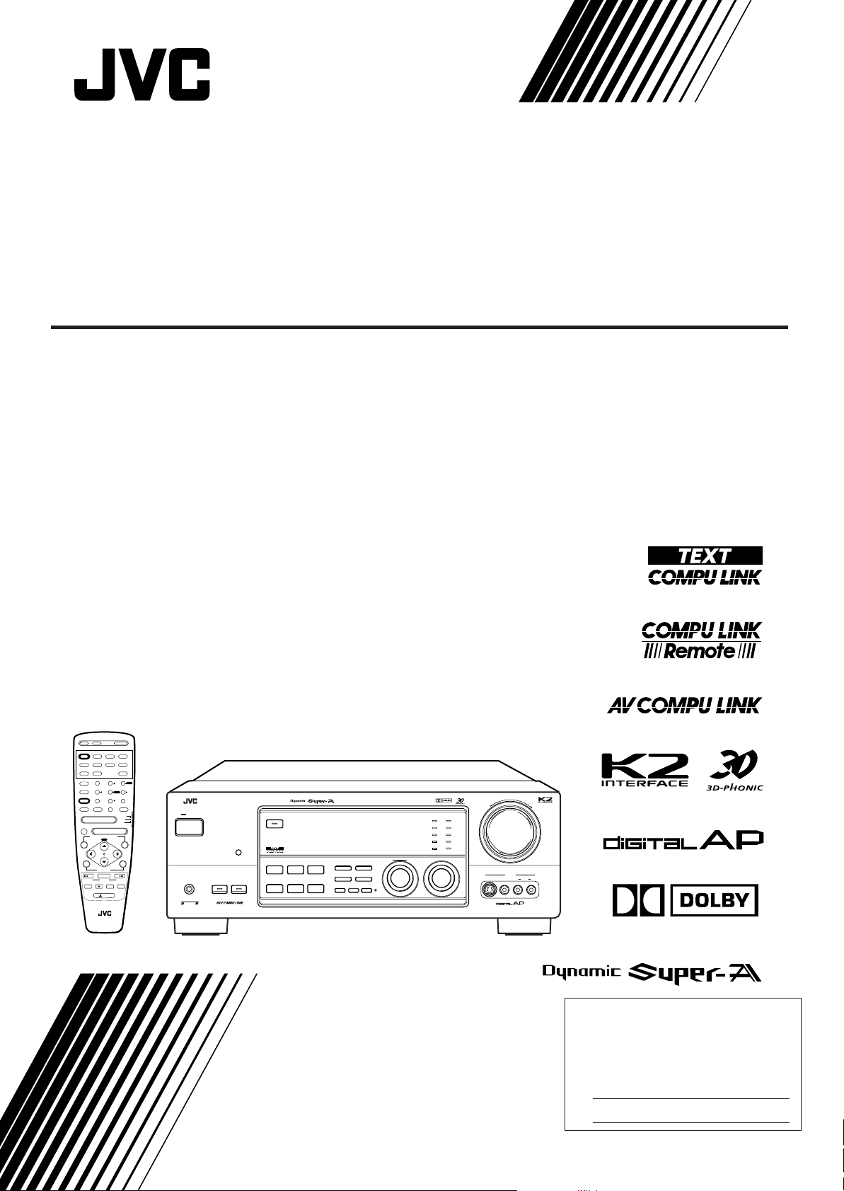
AUDIO/VIDEO CONTROL RECEIVER
RX-1024VBK
TV/CATV/
VCR 1
DBS
POWER
POWER POWER
VCR 2 VIDEO
DVD
VCR 1
CD TAPE/MD PHONO TV/DBS
AM
FM1SLEEP
CNTR TONE CNTR
SURROUND
MODE
DIGITAL/
TEST REAR · L
ANALOG
INPUT
456
EFFECT
SOUND
7
/P
SEA MODE
DISC
10
RETURN FM MODE/
MUTE
CHANNEL
–
MUTE
VOLUME
–
ON SCREEN CONTROL
MENU
SET EXIT
VCR1
CONTROL
/REW PLAY
DOWN TUNING UP
REC
TV/VIDEO
STOP
LIGHT
RM-SR1024U REMOTE CONTROL
AUDIO
–+
MENU
2 3
–+
ENTER
–+
REAR · R
809
SUBWOOFER
–+
+10
100+
AUDIO/
TV/VCR
CATV
+
DBS
+
TAPE
FF/
PAUSE
RX-1024V AUDIO/VIDEO CONTROL RECEIVER
STANDBY
POWER
PHONES
COMPULINK
Remote
SPEAKERS
12
MULTI JOG
DIGITAL
DVD
TV SOUND/DBS PHONO
VCR 2
VIDEO
SOURCE SELECTOR
DOLBY SURROUND
DSP MODE
BALANCE/SURROUND
ADJUST
SEA MODE
DIGITAL INPUT
SEA ADJUST SETTING
FM/AM TUNING TUNER PRESET
TUNER/SEA MEMORY FM MODE
SOUND SELECT
LOUDNESS ONE TOUCH OPERATION
SOURCE NAME
INPUT ATT.
INSTRUCTIONS
CD
TAPE/MDVCR 1
FM
AM
MASTER VOLUME
–
S-VIDEO VIDEO AUDIOLR
+
VIDEO
DIGITAL
For Customer Use:
Enter below the Model No. and Serial
No. which are located either on the rear,
bottom or side of the cabinet. Retain this
information for future reference.
Model No.
Serial No.
LVT0018-001A
[J]
Page 2
Warnings, Cautions and Others
CAUTION
RISK OF ELECTRIC SHOCK
DO NOT OPEN
CAUTION: TO REDUCE THE RISK OF ELECTRIC SHOCK.
DO NOT REMOVE COVER (OR BACK)
NO USER SERVICEABLE PARTS INSIDE.
REFER SERVICING TO QUALIFIED SERVICE PERSONNEL.
The lightning flash with arrowhead symbol,
within an equilateral triangle is intended to
alert the user to the presence of uninsulated
"dangerous voltage" within the product's
enclosure that may be of sufficient
magnitude to constitute a risk of electric
shock to persons.
The exclamation point within an equilateral
triangle is intended to alert the user to the
presence of important operating and
maintenance (servicing) instructions in the
literature accompanying the appliance.
WARNING: TO REDUCE THE RISK OF FIRE
OR ELECTRIC SHOCK, DO NOT EXPOSE
THIS APPLIANCE TO RAIN OR MOISTURE.
CAUTION
To reduce the risk of electrical shocks, fire, etc.:
1. Do not remove screws, covers or cabinet.
2. Do not expose this appliance to rain or moisture.
Caution –– POWER switch!
Disconnect the mains plug to shut the power off completely. The
POWER switch in any position does not disconnect the mains line.
The power can be remote controlled.
Caution –– SPEAKER LOAD SELECTOR switch!
Match the position of SPEAKER LOAD SELECTOR switch on the
back panel to the impedance of the speaker connected, to protect
from overheating.
G-1
Page 3
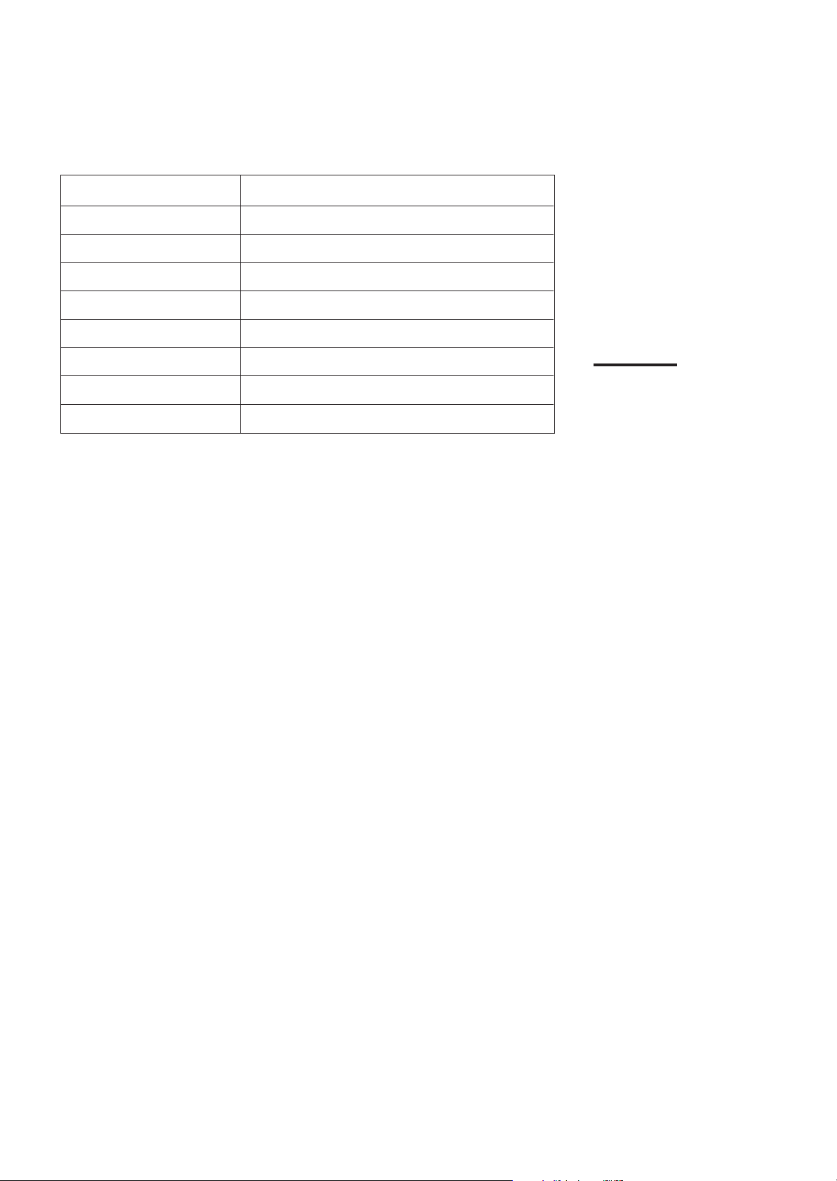
To get the best DSP (Digital Signal Processor) effect in your listening room, note the speaker
settings you have set on the table below for future reference (even though the receiver
memorizes the settings until you change them).
For actual setting procedures, see pages 19 to 21.
Speakers Setting
Front Speakers LARGE SMALL
Center Speaker LARGE SMALL NONE
Rear Speaker LARGE SMALL NONE
Center Delay Set to [ msec] (Select from 0 to 5 msec)
Rear Delay Set to [ msec] (Select from 0 to 15 msec)
Crossover Frequency 80 Hz 100 Hz 120 Hz
LFE Attenuator 0 dB 10 dB
Dynamic Range Compression
OFF MID MAX
Note:
If the power cord is unplugged
or a power failure occurs, all
preset settings will be erased in
a few days.
G-2
Page 4

Table of Contents
Parts Identification ...................................................................................... 3
Getting Started........................................................................................... 4
Before Installation................................................................................................................................................................... 4
Checking the Supplied Accessories ........................................................................................................................................ 4
Connecting the FM and AM Antennas ................................................................................................................................... 5
Connecting the Speakers......................................................................................................................................................... 6
Connecting Audio/Video Components ................................................................................................................................... 8
Connecting the Power Cord .................................................................................................................................................. 12
Putting Batteries in the Remote Control ............................................................................................................................... 12
Basic Operations ....................................................................................... 13
Turning the Power On and Off.............................................................................................................................................. 13
Selecting the Source to Play ................................................................................................................................................. 13
Adjusting the Volume............................................................................................................................................................ 14
Selecting the Front Speakers................................................................................................................................................. 15
Muting the Sound.................................................................................................................................................................. 15
Using the Sleep Timer........................................................................................................................................................... 15
Attenuating the Input Signal ................................................................................................................................................. 16
Adjusting the Subwoofer Output Level ................................................................................................................................ 16
Recording a Source ............................................................................................................................................................... 16
Basic Settings........................................................................................... 17
Changing the Source Name .................................................................................................................................................. 17
Selecting the Input Mode ...................................................................................................................................................... 17
Adjusting the Front Speaker Output Balance ....................................................................................................................... 18
Setting the Subwoofer Information....................................................................................................................................... 18
Listening at Low Volume (Loudness) ................................................................................................................................... 18
Digital Input (DIGITAL IN) Terminal Setting...................................................................................................................... 19
Setting the Speakers for the DSP Modes .............................................................................................................................. 19
One Touch Operation .................................................................................. 22
About the One Touch Operation ........................................................................................................................................... 22
Using the One Touch Operation............................................................................................................................................ 22
Receiving Radio Broadcasts ........................................................................ 23
Tuning in Stations Manually................................................................................................................................................. 23
Using Preset Tuning.............................................................................................................................................................. 23
Selecting the FM Reception Mode ....................................................................................................................................... 24
Assigning Names to Preset Stations ..................................................................................................................................... 25
Using the SEA Modes ................................................................................ 26
Selecting Your Favorite SEA Mode ...................................................................................................................................... 26
Creating Your Own SEA Mode............................................................................................................................................. 27
1
Page 5

Using the DSP Modes ................................................................................ 28
Using the 3D-PHONIC Modes ............................................................................................................................................. 29
Using the DAP Modes .......................................................................................................................................................... 32
Using the Dolby Digital and Dolby Pro Logic Modes ......................................................................................................... 34
Using the Theater Surround Mode........................................................................................................................................ 37
Using the On-Screen Menus........................................................................ 41
Selecting the Source to Play............................................................................................................................................ 41
Selecting the Different Sources for Picture and Sound................................................................................................... 41
Using the DSP Modes ..................................................................................................................................................... 41
Adjusting the Front Speaker Output Balance.................................................................................................................. 42
Listening at Low Volume (Loudness) ............................................................................................................................. 42
Attenuating the Input Signal ........................................................................................................................................... 42
Adjusting the Subwoofer Output Level........................................................................................................................... 43
Adjusting the DSP Modes ............................................................................................................................................... 43
Selecting Your Favorite SEA Mode ................................................................................................................................ 44
Creating Your Own SEA Mode ....................................................................................................................................... 45
Basic Settings .................................................................................................................................................................. 45
Operating the Tuner......................................................................................................................................................... 46
Storing the Preset Stations .............................................................................................................................................. 46
Assigning Names to the Preset Stations.......................................................................................................................... 47
COMPU LINK Remote Control System ......................................................... 48
TEXT COMPU LINK Remote Control System................................................. 49
Showing the Disc Information on the TV Screen ........................................................................................................... 50
Searching a Disc (Only for the CD Player)..................................................................................................................... 51
Using the User File (Only for the CD Player with the User File Function).................................................................... 53
Entering the Disc Information......................................................................................................................................... 54
AV COMPU LINK Remote Control System .................................................... 56
Operating JVC’s Audio/Video Components ................................................... 58
Operating Other Manufactures’ Components ............................................... 62
Troubleshooting......................................................................................... 68
Specifications............................................................................................ 69
2
Page 6
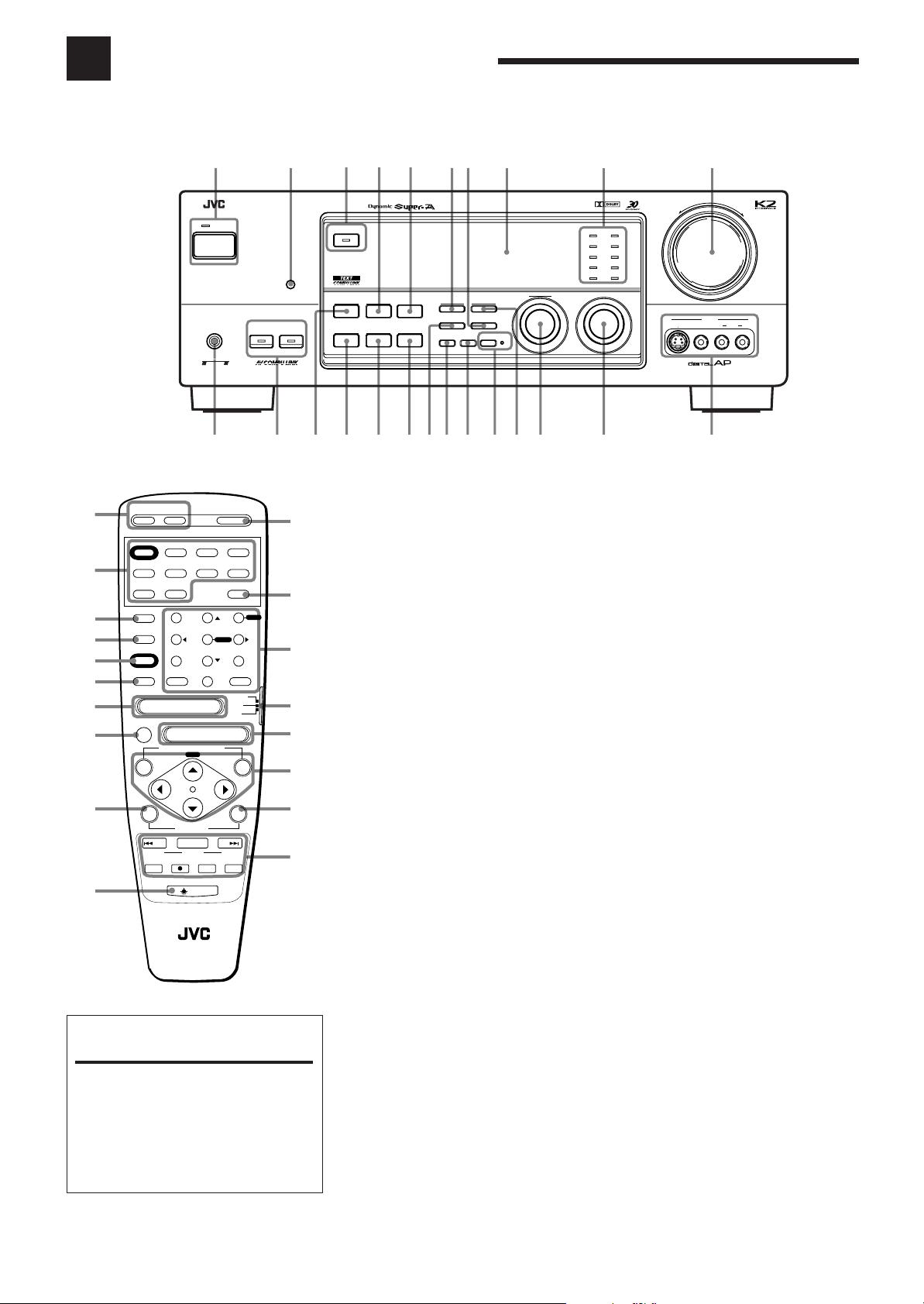
Parts Identification
Become familiar with the buttons and controls on the receiver before use.
123456 9 0
RX-1024V AUDIO/VIDEO CONTROL RECEIVER
STANDBY
POWER
+
¡
™
£
¢
∞
§
¶
•
ª
PHONES
COMPULINK
Remote
-
TV/CATV/
VCR 1
DBS
POWER POWER
POWER
DVD
CD TAPE/MD PHONO TV/DBS
AM
SURROUND
MODE
DIGITAL/
ANALOG
INPUT
SOUND
DISC
–
MUTE
SET EXIT
VCR1
/REW PLAY
DOWN TUNING UP
TV/VIDEO
RM-SR1024U REMOTE CONTROL
VCR 2 VIDEO
VCR 1
FM
CNTR TONE CNTR
–+
1
2 3
TEST REAR · L
–+
ENTER
456
EFFECT
–+
REAR · R
7/P809
SUBWOOFER
–+
SEA MODE
10
RETURN FM MODE/
MUTE
CHANNEL
ON SCREEN CONTROL
–
CONTROL
REC
+
VOLUME
MENU
STOP
LIGHT
AUDIO
FF/
PAUSE
SLEEP
AUDIO/
TV/VCR
CATV
DBS
TAPE
MENU
+10
100+
+
SPEAKERS
12
=
º
–
≠
Ÿ
⁄
¤
‹
›
When using the remote control
in the dark
Press LIGHT (ª).
The buttons on the remote control are
backlit while you are using the remote
control.
If you do not press any button for
about 5 seconds, backlight will turn
off.
7
8
DOLBY SURROUND
DSP MODE
SEA MODE
DIGITAL INPUT
BALANCE/SURROUND
SEA ADJUST SETTING
ADJUST
#% &
~
@
!
FM/AM TUNING TUNER PRESET
FM MODE
TUNER/SEA MEMORY
SOUND SELECT
LOUDNESS ONE TOUCH OPERATION
SOURCE NAME
INPUT ATT.
$^ *(
MULTI JOG
Refer to the pages in parentheses for details.
Front Panel
1
POWER button and STANDBY lamp (13)
2
Remote sensor (12)
3
DOLBY SURROUND button and lamp (36)
4
SEA MODE button (26) *
5
DIGITAL INPUT button (17)
6
FM/AM TUNING button (23) *
7
FM MODE button (24)
8
Display (13)
9
Source lamps (13)
0
MASTER VOLUME control (14)
-
PHONES jack (15)
=
SPEAKERS 1/2 buttons and lamps (15)
~
DSP MODE button (29) *
!
BALANCE/SURR OUND ADJUST button
(18, 30) *
@
SEA ADJUST button (27) *
#
SETTING button (18) *
$
TUNER/SEA MEMORY b utton (23, 25, 27)
%
SOUND SELECT/INPUT ATT. button
(14, 16)
^
LOUDNESS/SOURCE NAME button
(17, 18)
&
ONE TOUCH OPERATION button and
lamp (22)
*
TUNER PRESET button (24) *
(
MULTI JOG control
What this control actually does
depends on which function you are
trying to adjust. Before using this
control, select the function by
pressing one of the buttons marked
with *.
)
SOURCE SELECTOR control (13)
_
VIDEO input jacks (10)
DIGITAL
DVD
TV SOUND/DBS PHONO
VCR 2
VIDEO
SOURCE SELECTOR
CD
TAPE/MDVCR 1
FM
AM
MASTER VOLUME
–
S-VIDEO VIDEO AUDIOLR
+
VIDEO
)_
Remote Control
+
TV/CATV/DBS POWER and VCR1
POWER buttons (60, 61)
¡
Source selecting buttons (14)
™
SURROUND MODE button (31)
£
DIGITAL/ANALOG INPUT button (17)
¢
SOUND button (26, 31, 58)
∞
DISC button (59)
§
CHANNEL buttons (+/–) (60, 62)
¶
MUTE button (15)
•
VCR1 CONTROL button (60, 64)
ª
LIGHT button
º
AUDIO POWER button (13)
–
SLEEP button (15)
≠
10 keys for selecting preset channel (24)
10 keys for adjusting sound (26, 31)
10 keys for operating audio/video
components (58, 62)
Ÿ
Remote control mode selector (AUDIO/
TV/VCR, CATV, DBS) (13, 58, 62)
To operate an audio system, TV,
and VCR, set this selector to
“AUDIO/TV/VCR.”
To operate a CATV converter, set
this selector to “CATV.”
To operate a DBS tuner, set this
selector to “DBS.”
⁄
VOLUME buttons (+/–) (14)
¤
MENU operating buttons (SET, EXIT, %,
fi, @, #) (41)
‹
TAPE CONTROL button (59)
›
Operating buttons for audio/video
components (58, 62)
3
Page 7

Getting Started
This section explains how to connect audio/video components and speakers to the receiver, and how to
connect the power supply.
Before Installation
General
• Be sure your hands are dry.
• Turn the power off to all components.
• Read the manuals supplied with the components you are going to connect.
Locations
• Install the receiver in a location that is level and protected from moisture.
• The temperature around the receiver must be between 23˚ and 95˚ F (–5˚ and 35˚ C).
• Make sure there is good ventilation around the receiver. Poor ventilation could cause
overheating and damage the receiver.
Handling the receiver
• Do not insert any metal object into the receiver.
• Do not disassemble the receiver or remove screws, covers, or cabinet.
• Do not expose the receiver to rain or moisture.
Checking the Supplied Accessories
Check to be sure you have all of the following items, which are supplied with the
receiver.
The number in the parentheses indicates quantity of the pieces supplied.
• Remote Control (1)
• Batteries (2)
• AM Loop Antenna (1)
• FM Antenna (1)
If anything is missing, contact your dealer immediately.
4
Page 8
Getting Started
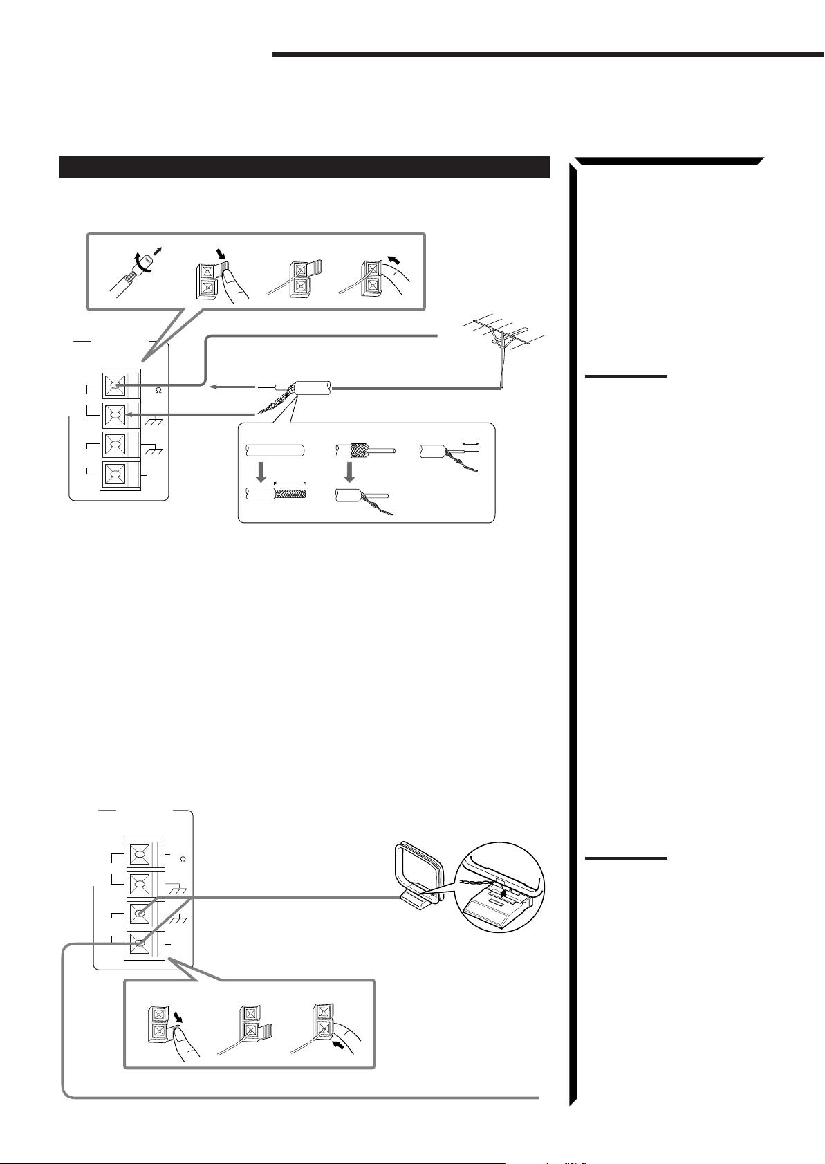
Connecting the FM and AM Antennas
FM Antenna Connections
4
Outside FM Antenna Wire
3
2
7/16 in.
(10 mm)
ANTENNA
FM
AM
LOOP
FM
75
GND
GND
AM
EXT
21
FM Antenna
3
Extend the FM wire antenna horizontally.
4
1
13/16 in.
(20 mm)
How to strip the 75Ω coaxial cable and connect it to the FM
terminals
1. Strip back the outside covering of the 75Ω coaxial cable to expose the braided
metallic mesh about 13/16 inches (20 mm).
2. Pull the mesh back and twist it into a single connector as shown in the illustration
above.
3. Strip the insulation about 7/16 inches (10 mm) back from the central wire.
4. Insert the twisted mesh and the central wire to the FM terminals, as shown in the
illustration above.
Note:
If reception is poor, connect the
outside antenna.
Before attaching a 75Ω coaxial
cable (the kind with a round wire
going to an outside antenna),
disconnect the supplied FM wire
antenna.
AM Antenna Connections
ANTENNA
FM
FM
AM
LOOP
75
GND
GND
AM
EXT
1
AM Loop Antenna
2
5
Turn the loop until you
have the best reception.
Notes:
• Make sure the antenna
conductors do not touch any
other terminals, connecting
cords and power cord. This
Snap the tabs on the loop
into the slots of the base to
assemble the AM loop.
3
Outdoor single vinylcovered wire
could cause poor reception.
• If reception is poor, connect
an outdoor single vinylcovered wire to the AM EXT
terminal. (Keep the AM loop
antenna connected.)
Page 9
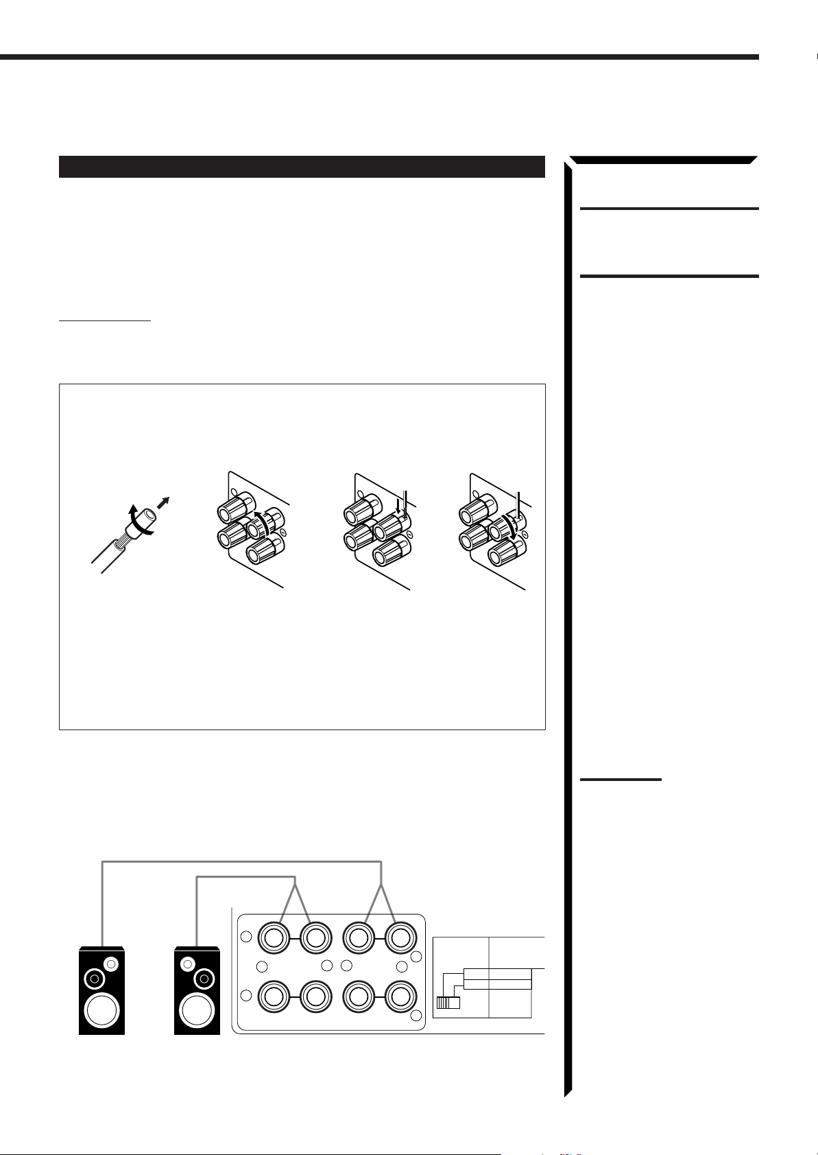
Connecting the Speakers
RIGHT
1
You can connect the following speakers:
• Two pairs of front speakers to produce normal stereo sound.
• One pair of rear speakers to enjoy the surround effect.
• One center speaker to produce more effective surround effect (to emphasize human
voices).
CAUTION:
Use speakers with the
SPEAKER IMPEDANCE
indicated by the speaker
terminals.
• One subwoofer to enhance the bass.
IMPORTANT:
After connecting the speakers listed above, set the speaker setting information
properly to obtain the best possible performance. For details, see pages 18 and 19.
For each speaker (except for subwoofer), connect the (–) and (+) terminals on the
rear panel to the (–) and (+) terminals marked on the speakers. For connecting a
subwoofer, see page 7.
134
2
1
RIGHT
1
RIGHT
1 Cut, twist and remove the insulation at the end of each speaker signal cable.
2 Turn the knob counterclockwise.
3 Insert the speaker signal cable.
4 Turn the knob clockwise.
Connecting the front speakers
Connect the front speakers to the FRONT SPEAKERS terminals.
You can connect two pairs of front speakers (one pair to the FRONT SPEAKERS 1
terminals, and another pair to the FRONT SPEAKERS 2 terminals).
1
+
2
Right speakerLeft speaker
–+–
RIGHT LEFT
FRONT SPEAKERS
1
2
SPEAKER
LOAD
SELECTOR
LOW
HIGH
SPEAKER LOAD
POSITIONED LOW
SPEAKER LESS
4 ~ 6
8 ~ 16
SPEAKER
IMPEDANCE
/ OHMS
Note:
To obtain the best possible
output power from the receiver,
and to prevent the receiver from
being overheated, the receiver
has the SPEAKER LOAD
SELECTOR which has to be set
as follows:
• Set it to the HIGH position
when the impedance of the
speakers connected is within
the range of 8 ohms to 16
ohms.
• Set it to the LOW position
when the impedance of the
speakers connected is within
the range of 4 ohms to 6
ohms.
• Set it to the LOW position
when the impedance of the
any speaker connected is 6
ohms or less.
6
Page 10
Getting Started
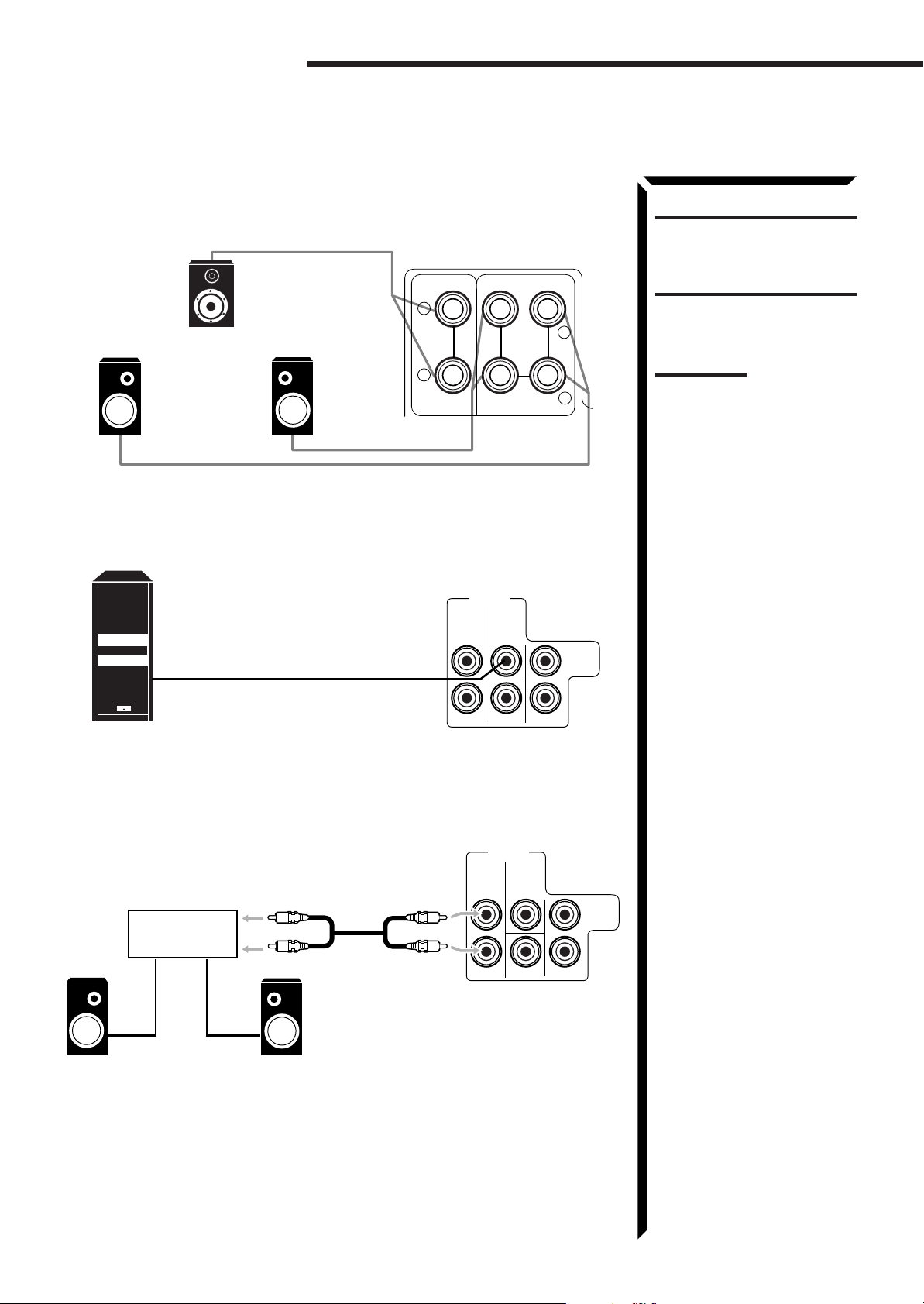
Connecting the rear and center speakers
Connect the rear speakers to the REAR SPEAKERS terminals and a center speaker to
the CENTER SPEAKER terminals.
Center speaker
REAR
SPEAKERS
SUB
LEFT
+
–
FRONT
LEFT
RIGHT
+
Left rear speaker
Right rear speaker
–
CENTER
SPEAKER
Connecting the subwoofer speaker
Connect the input jack of a powered subwoofer to the SUBWOOFER jack on the rear
panel, using a cable with RCA pin plugs.
PRE OUT
REAR
LEFT
WOOFER
Powered subwoofer
RIGHT RIGHT
CENTER
CAUTION:
Use speakers with the
SPEAKER IMPEDANCE
indicated by the speaker
terminals.
Note:
To obtain the best possible
output power from the receiver,
and to prevent the receiver from
being overheated, the receiver
has the SPEAKER LOAD
SELECTOR which has to be set
as follows:
• Set it to the HIGH position
when the impedance of the
speakers connected is within
the range of 8 ohms to 16
ohms.
• Set it to the LOW position
when the impedance of the
speakers connected is within
the range of 4 ohms to 6
ohms.
• Set it to the LOW position
when the impedance of the
any speaker connected is 6
ohms or less.
To enhance your audio system
You can use this receiver as the pre-amplifier (control amplifier) when you connect
power amplifiers to the PRE OUT jacks on the rear panel, using cables with RCA pin
plugs.
Example: When using a stereo power amplifier
for connecting the rear speakers
Power amplifier
Left rear speaker
Right rear speaker
PRE OUT
REAR
SUB
LEFT
WOOFER
RIGHT RIGHT
CENTER
FRONT
LEFT
7
Page 11
Connecting Audio/Video Components
You can connect the following audio/video components to this receiver. Refer also to the
manuals supplied with your components. If you want to connect a component not listed
in the table below, refer to the manual supplied with it.
Audio Components Video Components
• Turntable • DVD player*
• CD player* • TV
• Cassette deck or MD recorder* • DBS tuner*
• VCRs
• Video camera
* You can connect these components using the methods described in “Analog
connections” (below) or in “Digital connections” (see page 11).
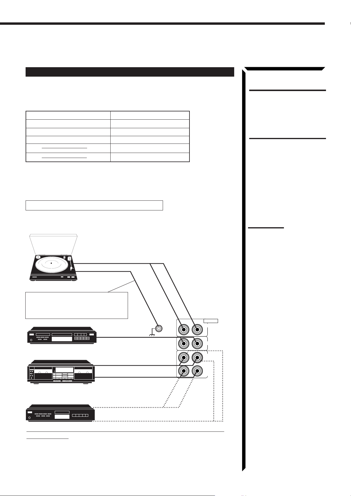
Analog connections
Audio component connections
Use the cables with RCA pin plugs (not supplied).
Connect the white plug to the audio left jack, and the red plug to the audio right jack.
To audio output
Turntable
If an earth cable is provided for your
turntable, connect the cable to the
screw marked GND on the rear panel.
AUDIO
PHONO
CD
OUT
(REC)
TAPE
/MD
IN
(PLAY)
CD player
Cassette deck
or
MD recorder
To audio output
To audio input
To audio output
To audio output
GND
RIGHT LEFT
CAUTION:
If you connect a soundenhancing device such as a
graphic equalizer between the
source components and this
receiver, the sound output
through this receiver may be
distorted.
Notes:
• Any turntables incorporating
a small-output cartridge such
as an MC (moving-coil type)
must be connected to this
receiver through a
commercial head amplifier or
step-up transformer. Direct
connection may result in
insufficient volume.
• You can connect either a
cassette deck or an MD
recorder to the TAPE/MD
jacks. When connecting an
MD recorder to the TAPE/MD
jacks, change the source
name, which will be shown on
the display when selected as
the source, to “MD.” See page
17 for details.
To audio input
If your audio components have a COMPU LINK-3 or TEXT COMPU
LINK terminal
• See also page 48 for detailed information about the connection and the COMPU
LINK-3 remote control system.
• See also page 49 for detailed information about the connection and the TEXT
COMPU LINK remote control system.
8
Page 12
Getting Started
Video component connections
Use the cables with RCA pin plugs (not supplied).
Connect the white plug to the audio left jack, the red plug to the audio right jack, and
the yellow plug to the video jack.
If your video components have S-video (Y/C-separation) terminals, connect them using
S-video cables (not supplied). Connecting these video components through the S-video
input/output terminals will give you better picture playback (or recording) quality.
IMPORTANT:
This receiver is equipped with both the composite video and S-video input/output
terminals for connecting video components.
You do not have to connect both the composite video and S-video terminals.
However, remember that the video signals from the composite video input
terminals are output only through the composite video output terminals,
while the ones from the S-video input terminals are output only through the
S-video output terminals.
Therefore, if a recording video component and a playing video component are
connected to the receiver through the different video terminals, you cannot record
the picture from the playing component on the recording component. In addition,
if the TV and a playing video component are connected to the receiver through the
different video terminals, you cannot view the playback picture from the playing
component on the TV.
To view and record the playback picture from the video component connected
to the VCR 2 jacks, you must connect the TV and the recording video
component through the composite video terminals.
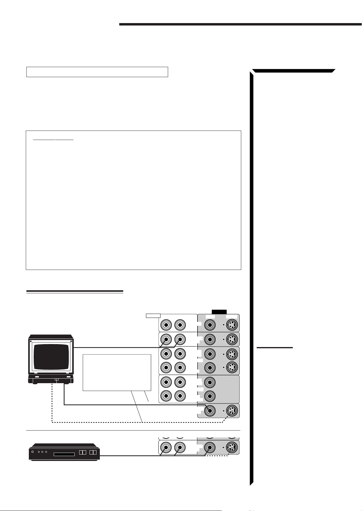
Connecting the TV and/or DBS tuner
You can connect either the TV or DBS tuner to the TV SOUND/DBS jacks.
VIDEO
VIDEO S-VIDEORIGHT LEFT
TV
To audio output
To composite video input
To S-video input
DBS tuner
DBS
Connect the TV to the
MONITOR OUT jack to
view the playback picture
from the other connected
video components.
To audio/video output
RIGHT
AUDIO
DVD
TV SOUND
/DBS
OUT
(REC)
VCR 1
IN
(PLAY)
OUT
(REC)
VCR 2
IN
(PLAY)
MONITOR
OUT
TV SOUND
/DBS
Notes:
• When connecting the TV to
the TV SOUND/DBS jacks,
DO NOT connect the TV’s
video output to these video
input terminals.
• When connecting the DBS
tuner to the TV SOUND/DBS
jacks, change the source
name, which will be shown on
the display when selected as
the source, to “DBS.” See
page 17 for details.
• To enjoy Dolby Digital with the
DBS tuner as the source,
connect the DBS tuner using
the method described in
“Digital connections” on page
11.
9
Page 13
Connecting DVD player
DVD player
DVD
To audio/video
output
RIGHT
AUDIO
DVD
TV SOUND
/DBS
Note:
VIDEO
VIDEO S-VIDEORIGHT LEFT
To enjoy Dolby Digital with the
DVD player as the source,
connect the DVD player, using
the method described in “Digital
connections” on page 11.
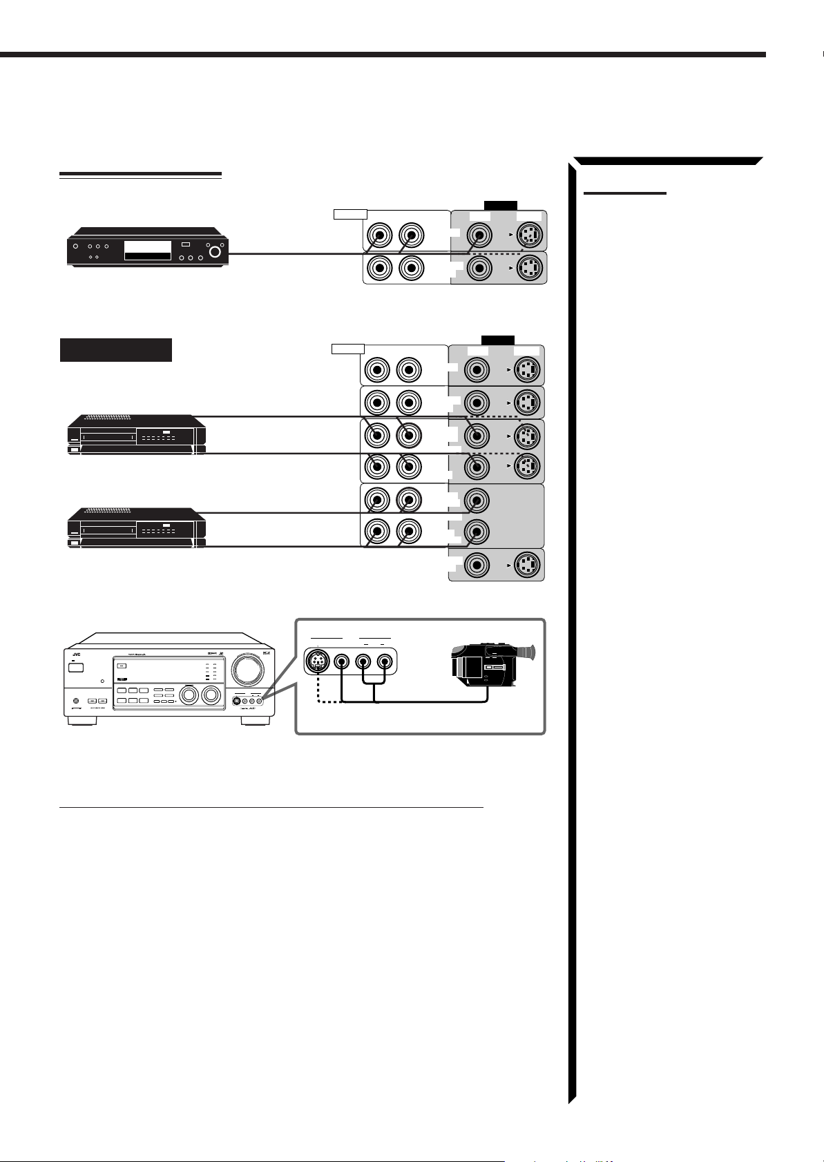
Connecting VCRs
S-VHS (or VHS) VCR
S-VHS
VHS VCR
VHS
RX-1024VAUDIO/VIDEO CONTROL RECEIVER
STANDBY
SPEAKERS
12
DOLBY SURROUND
BALANCE/SURROUND
DSP MODE
SEA MODE
DIGITAL INPUT
FM/AM TUNING TUNER PRESET
TUNER/SEA MEMORY FM MODE
SEA ADJUST SETTING
ADJUST
SOUND SELECT
LOUDNESS ONE TOUCH OPERATION
SOURCE NAME
INPUT ATT.
POWER
PHONES
COMPULINK
Remote
To audio/video input
To audio/video output
To audio/video input
To audio/video output
MASTER VOLUME
DIGITAL
–
VIDEO
S-VIDEO VIDEO AUDIOLR
+
CD
DVD
TV SOUND/DBS PHONO
TAPE/MDVCR 1
FM
VCR 2
VIDEO
AM
MULTI JOG
SOURCE SELECTOR
RIGHT
AUDIO
VIDEO
S-VIDEO VIDEO AUDIOLR
To audio/video output
VIDEO S-VIDEORIGHT LEFT
DVD
TV SOUND
/DBS
OUT
(REC)
VCR 1
IN
(PLAY)
OUT
(REC)
VCR 2
IN
(PLAY)
MONITOR
OUT
Video camera
VIDEO
If your video components have an AV COMPU LINK terminal
See also page 56 for detailed information about the connection and the AV COMPU
LINK remote control system.
10
Page 14
Getting Started
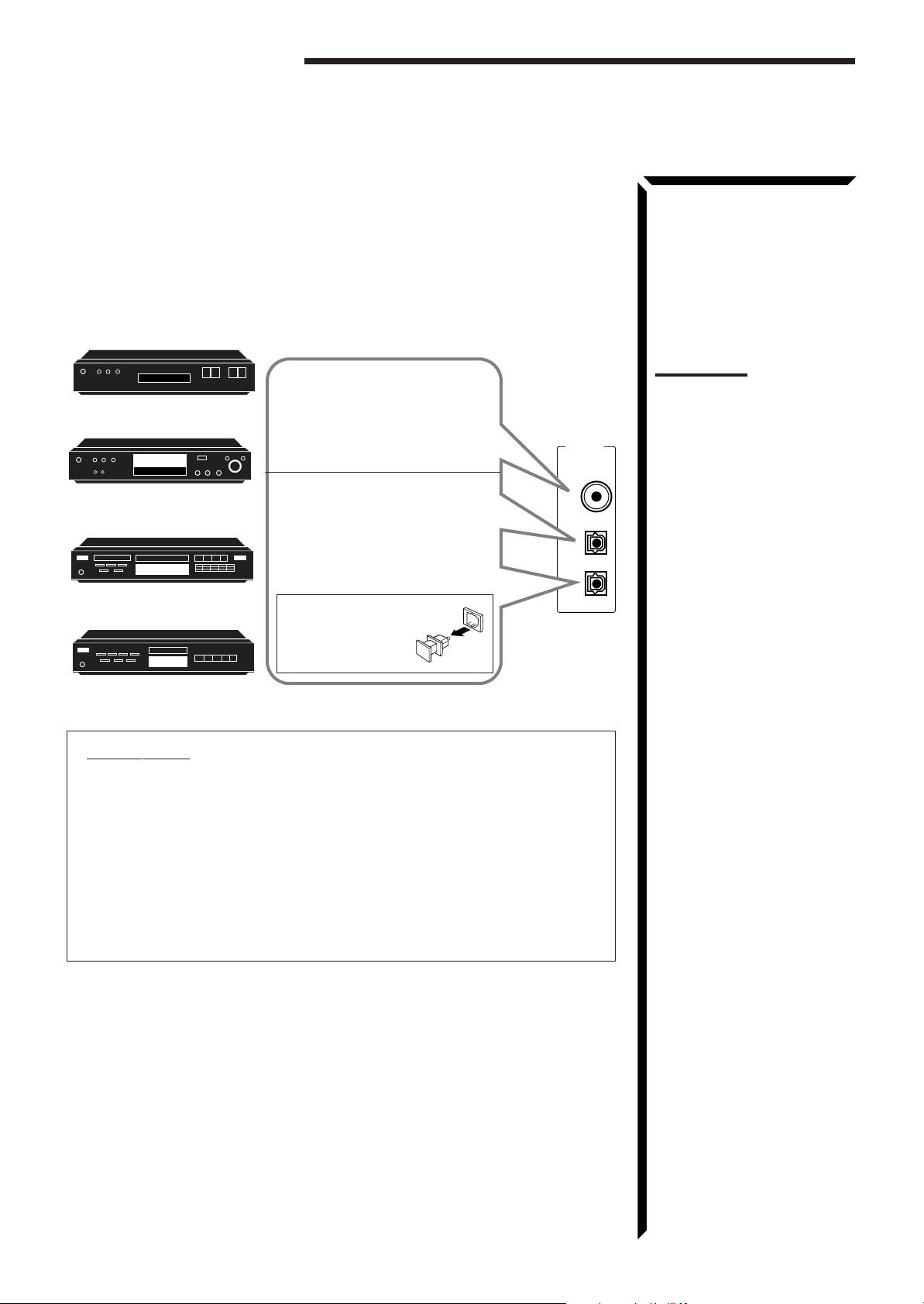
Digital connections
This receiver is equipped with three DIGITAL IN terminals — one digital coaxial
terminal and two digital optical terminals.
To enjoy Dolby Digital, you have to connect the source components using the DIGITAL
IN terminals.
You can connect any component to any one of the digital terminals using the digital
coaxial cable (not supplied) or digital optical cable (not supplied).
DBS tuner
DBS
DVD player
DVD
CD player
MD recorder
When the component has a digital
coaxial output terminal, connect it
to the DIGITAL1 (DBS) terminal,
using the digital coaxial cable (not
supplied).
When the component has a digital
optical output terminal, connect it
to the DIGITAL2 (DVD) or
DIGITAL3 (CD) terminal, using the
digital optical cable (not supplied).
Before connecting a
digital optical cable,
unplug the protective
plug.
DIGITAL IN
PCM/DOLBY DIGITAL
DIGITAL 1 (DBS)
DIGITAL 2 (DVD)
DIGITAL 3 (CD)
Notes:
• When shipped from the
factory, the DIGITAL IN
terminals has been set for use
with the following
components.
– DIGITAL 1 (coaxial): For
DBS tuner
– DIGITAL 2 (optical): For
DVD player
– DIGITAL 3 (optical): For CD
player
• When you want to operate the
CD player or MD recorder
using the COMPU LINK
remote control system,
connect the target component
also as described in “Analog
connections” (see page 8).
IMPORTANT:
• When connecting the DVD player or the DBS tuner using the digital terminal,
you also need to connect it to the video jack (either composite video terminal
or S-video terminal) on the rear. Without connecting it to the video jack, you
can view no playback picture.
• After connecting the above components using the DIGITAL IN terminals, set
the following correctly if necessary.
– Select the digital input mode correctly. For details, see “Selecting the Input
Mode” on page 17.
– Set the digital input (DIGITAL IN) terminal setting correctly. For details,
see “Digital Input (DIGITAL IN) Terminal Setting” on page 19.
11
Page 15
Connecting the Power Cord
Before plugging the receiver into an AC outlet, make sure that all connections have been
made.
When the power cord is connected, the STANDBY lamp above the POWER button
lights up.
Keep the power cord away from the connecting cables and antenna. The power cord
may cause noise or screen interference. We recommend that you use a coaxial cable to
connect the antenna, since it is well-shielded against interference.
Putting Batteries in the Remote Control
Before using the remote control, put two supplied batteries first. When using the remote
control, aim the remote control directly at the remote sensor on the receiver.
Notes:
• A small amount of power is
always consumed even in
standby mode. To switch off
the power completely, unplug
the power cord from the AC
outlet.
• If the power cord is unplugged
or a power failure occurs,
preset settings will be erased
in a few days.
CAUTIONS:
• Do not touch the power cord
with wet hands.
• Do not pull on the power cord
to unplug the cord. When
unplugging the cord, always
grasp the plug so as not to
damage the cord.
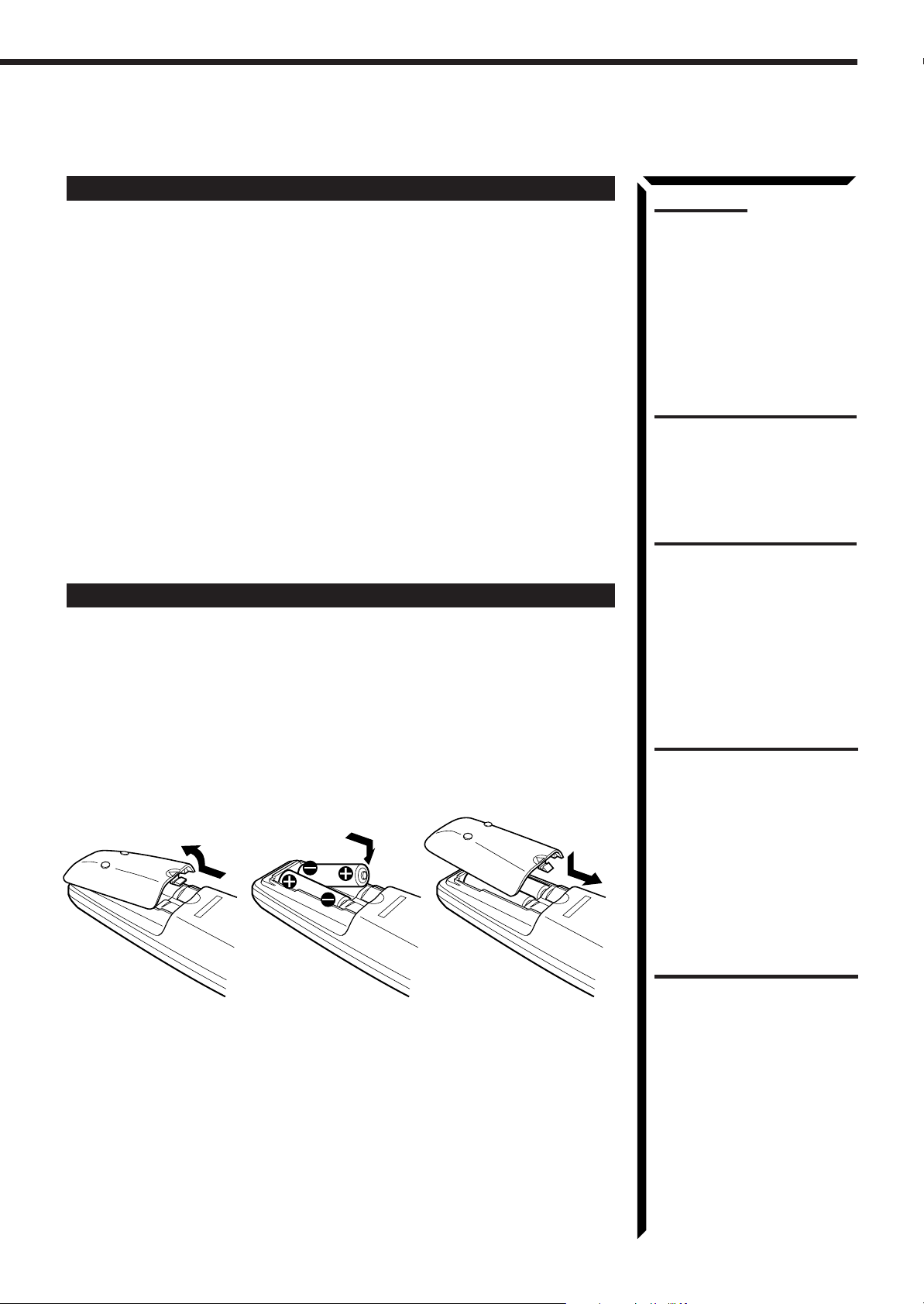
1. On the back of the remote control, remove the battery cover as illustrated.
2. Insert batteries. Make sure to observe the proper polarity: (+) to (+) and (–) to
(–).
3. Replace the cover.
R6P (SUM-3)/AA (15F)
If the range or effectiveness of the remote control decreases, replace the batteries. Use
two R6P (SUM-3)/AA (15F) type dry-cell batteries.
CAUTION:
Follow these precautions to
avoid leaking or cracking cells:
• Place batteries in the remote
control so they match the
polarity indicated: (+) to (+)
and (–) to (–).
• Use the correct type of
batteries. Batteries that look
similar may differ in voltage.
• Always replace both batteries
at the same time.
• Do not expose batteries to
heat or flame.
12
Page 16
Basic Operations
POWER
STANDBY
POWER
STANDBY
The following operations are commonly used when you play any sound source.
IMPORTANT:
When using the Remote Control, check to see if its remote control
mode selector is set to the correct position:
AUDIO/
TV/VCR
CATV
DBS
To operate an audio system, TV, and VCR, set it to “AUDIO/TV/
VCR.”
To operate a CATV converter, set it to “CATV.”
To operate a DBS tuner, set it to “DBS.”
Turning the Power On and Off
On the front panel:
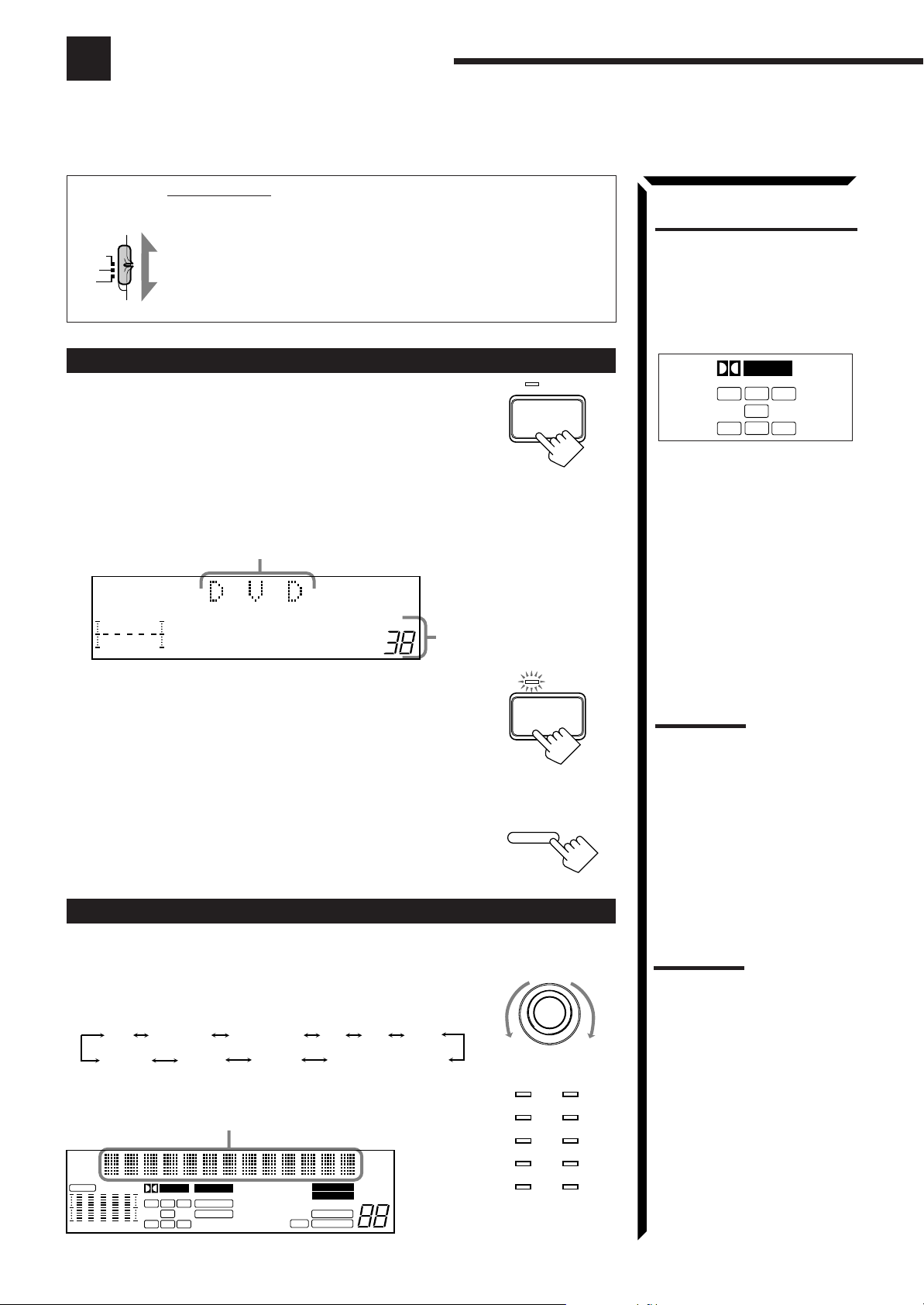
To turn on the power, press POWER.
The STANDBY lamp goes off. The name of the current source (or
station frequency) appears on the display.
• When the TV is connected to the TV SOUND/DBS jacks on the rear:
The receiver automatically turns on and select “TV SOUND” as the source about 5
seconds after you turn on the TV. (If you change the source name from “TV
SOUND” to “DBS,” the receiver will not turn on along with the TV. See page 17)
Current source name appears
FR
100 1k 10k
VOLUME
Current volume level
is shown here
What are the following
indicators?
When you select the source
encoded with Dolby Digital and
start playback, the following
indicators light up on the display
to show the signal being input to
this receiver. (Only the indicators
for the received signals light up.)
DIGITAL
C
L
LS
L: Left front channel
R: Right front channel
C: Center channel
LS: Left rear channel
RS: Right rear channel
S: Rear channel (monaural)
LFE: Subwoofer channel
LFE
S
R
RS
To turn off the power, press POWER again.
The STANDBY lamp lights up.
From the remote control:
To turn on the power, press AUDIO POWER.
The STANDBY lamp goes off. The name of the current source (or
station frequency) appears on the display.
To turn off the power, press AUDIO POWER again.
The STANDBY lamp lights up.
Selecting the Source to Play
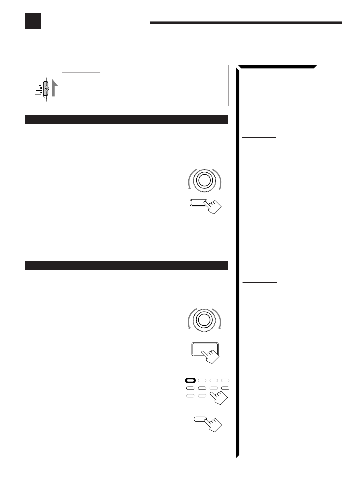
On the front panel:
Turn SOURCE SELECTOR until the source name you want
appears on the display.
As you turn the selector, the source changes as follows:
PHONOCD TAPE/MD AM DVD
VIDEO
The selected source lamp also lights up.
Selected source name appears
CH–
CNTR
S E A
FR
100 1k 10k
13
DIGITAL
L
LS
PRO LOGIC
C
R
D S P
LEE
3D-PHONC
S
RS
VCR1VCR2
THEATER DRAMA
LIVE CLUB ACTION
DANCE CLUB
HALL HEADPHONE
PA VILION
FM
TV SOUND/DBS
TUNED
STEREO
MUTE AUTO
LOUDNESS
VOLUME
SLEEPATT
AUDIO
POWER
SOURCE SELECTOR
DVD
TV SOUND/DBS PHONO
VCR 2
CD
TAPE/MDVCR 1
FM
AMVIDEO
Source lamps on the
front panel
Note:
When you turn off the receiver
with the TV kept turned on, the
receiver will turn on soon again.
To prevent this from happening,
make sure that you turn off the
TV before turning off the
receiver.
Note:
When connecting an MD
recorder (to the TAPE/MD
jacks), and a DBS tuner (to the
TV SOUND/DBS jacks), change
the source name appears on the
display. For details, see page
17.
Page 17
From the remote control:
SOURCE SELECTOR
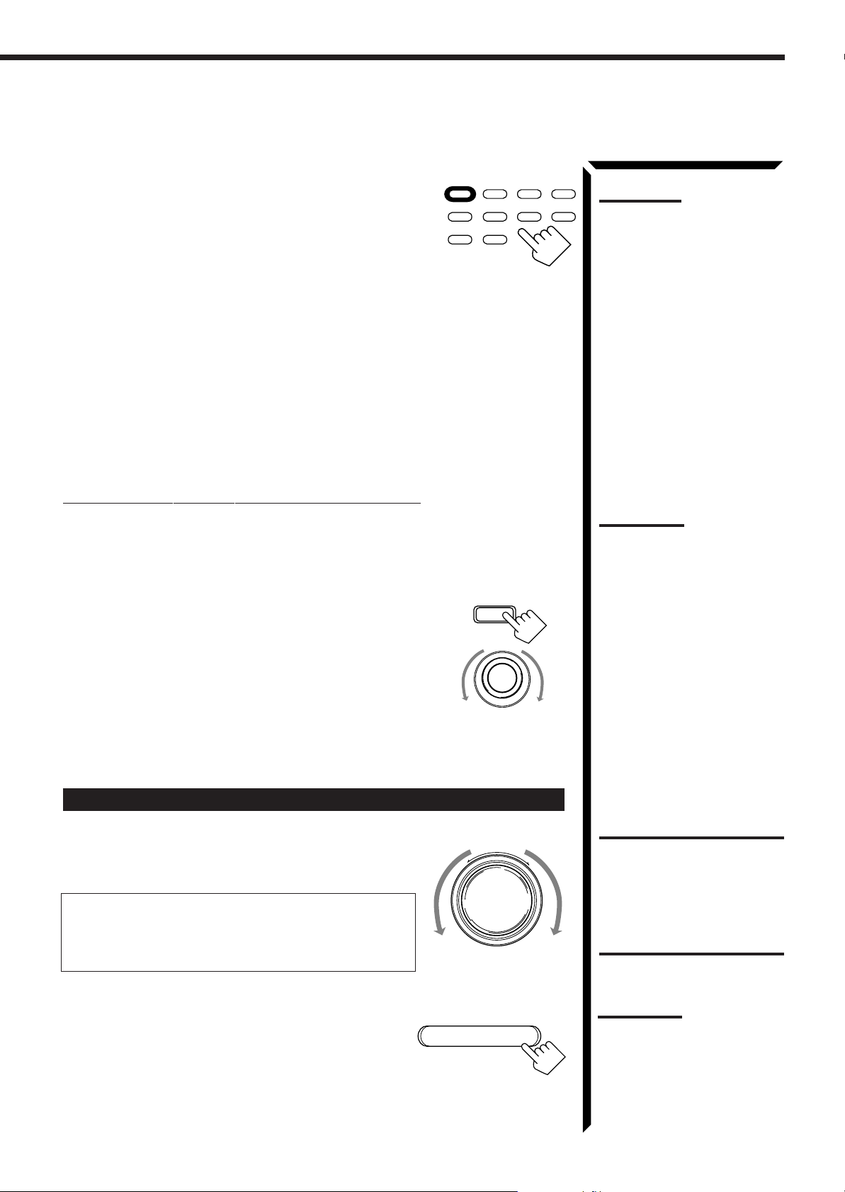
Press one of the source selecting buttons directly.
DVD Selects the DVD player.
VCR1 Selects the video component connected to the VCR1
jacks.
VCR2 Selects the video component connected to the VCR2
jacks.
VIDEO Selects the video component connected to the
VIDEO jacks.
CD* Selects the CD player.
TAPE/MD* Selects the cassette deck or the MD recorder.
PHONO* Selects the turntable.
FM* Selects an FM broadcast.
AM* Selects an AM broadcast.
TV/DBS • Selects TV sounds when the remote control selector is set to “AUDIO/
TV/VCR.”
• Selects the DBS tuner when the remote control selector is set to “DBS.”
Selecting different sources for picture and sound
You can watch picture from a video component while listening to sound from another
component.
VCR 1 VCR 2 VIDEO
DVD
CD TAPE/MD PHONO TV/DBS
AM FM
On the front panel:
1. Press SOUND SELECT briefly while viewing the picture from
a video component such as the VCR or DVD player, etc.
“SOUND SELECT” appears on the display.
2. Turn SOURCE SELECTOR to select the sound (except the TV
sound), while the indication of the above step is still on the
display.
SOUND SELECT
INPUT ATT.
Note:
When you press one of the
source selecting buttons
marked above with an asterisk
(*), the receiver automatically
turns on.
Notes:
• Once you have selected a
video source, pictures of the
selected source is sent to the
TV until you select another
video source.
• When you select TV sound as
the source, this function does
not work.
From the remote control:
Press one of the audio source selecting buttons (CD, TAPE/MD, PHONO, FM, AM),
while viewing the picture from a video component such as the VCR or DVD player, etc.
Adjusting the Volume
On the front panel:
To increase the volume, turn MASTER VOLUME clockwise.
To decrease the volume, turn it counterclockwise.
When you turn MASTER VOLUME rapidly, the volume
level also changes rapidly.
When you turn MASTER VOLUME slowly, the volume
level also changes slowly.
–
MASTER VOLUME
+
From the remote control:
To increase the volume, press VOLUME +.
To decrease the volume, press VOLUME –.
VOLUME
–
+
CAUTION:
Always set the volume to the
minimum before starting any
source. If the volume is set at its
high level, the sudden blast of
sound energy can permanently
damage your hearing and/or
ruin your speakers.
Note:
The volume level can be
adjusted within the range of “0”
(minimum) to “90” (maximum).
14
Page 18
Basic Operations
SLEEP
Selecting the Front Speakers
On the front panel
When you have connected two pairs of the front speakers, you can
select which to use.
Press SPEAKERS 1 or SPEAKERS 2 to select the speaker to use.
Each time you press the button, the lamp on the respective button turns on and off.
When the lamp on either button lights up, the respective speakers are activated.
IMPORTANT:
You can activate two pairs of the front speakers at the same time only when the
SPEAKER LOAD SELECTOR on the rear panel is set to “HIGH” and when no
signals are sent to the center and rear speakers. Otherwise, activating one pair of
the speakers deactivates the other.
only
:
SPEAKERS
12
Note:
If you use any of the DSP
modes other than the 3DPHONIC modes and
“HEADPHONE” with both front
speakers activated, the
speakers connected to the
FRONT SPEAKERS
terminals are deactivated.
CAUTION:
Be sure to turn down the volume
before connecting or putting on
headphones, as high volume
can damage both the
headphones and your hearing.
2
Listening only with headphones
1. Connect a pair of headphones to the PHONES jack on the front panel.
2. Press SPEAKERS 1 and/or 2 so that no lamps on the buttons are turned on.
Muting the Sound
From the remote control
Press MUTE to mute the sound through all speakers and
only
:
MUTE
headphones connected.
“MUTE” appears on the display and the volume turns off (the
volume level indicator also goes off).
To restore the sound, press MUTE again so that “OFF” appears on the display.
Turning MASTER VOLUME or pressing VOLUME +/– also restores the sound at the
previous volume level.
Using the Sleep Timer
Using the Sleep Timer, you can fall asleep to music and know the receiver will turn off
by itself rather than play all night.
From the remote control
only
:
Press SLEEP repeatedly.
The SLEEP indicator lights up on the display, and the shut-off
time on the display changes as follows.
= SLEEP 10min. = SLEEP 20min. = SLEEP 30min. = SLEEP 40min.
= SLEEP 50min. = SLEEP 60min. = SLEEP 70min. = SLEEP 80min.
= SLEEP 90min. = SLEEP 00min. (Canceled) = (back to the beginning)
When the shut-off time comes
The receiver turns off automatically.
Note:
You cannot shut off the sound
through the subwoofer using the
SPEAKERS 1 and 2 buttons.
Note:
When the TV is connected to the
TV SOUND/DBS jacks on the
rear:
The receiver will turn on soon
again after the Sleep Timer shut
off the receiver if the TV is kept
turned on.
To prevent this from happening,
make sure that you turn off the
TV before the Sleep Timer turns
off the receiver.
To check or change the time remaining until the shut-off time
Press SLEEP once. The remaining time until the shut-off time appears in minutes.
• To change the shut-off time, press SLEEP repeatedly.
To cancel the Sleep Timer
Press SLEEP repeatedly until “SLEEP 00min.” appears on the display. (The SLEEP
indicator goes off.)
Turning off the power also cancels the Sleep Timer.
15
Page 19
Attenuating the Input Signal
When the input level of the playing source through the analog terminals is too high, the
sounds will be distorted. If this happens, you need to attenuate the input signal level to
prevent the sound distortion.
On the front panel
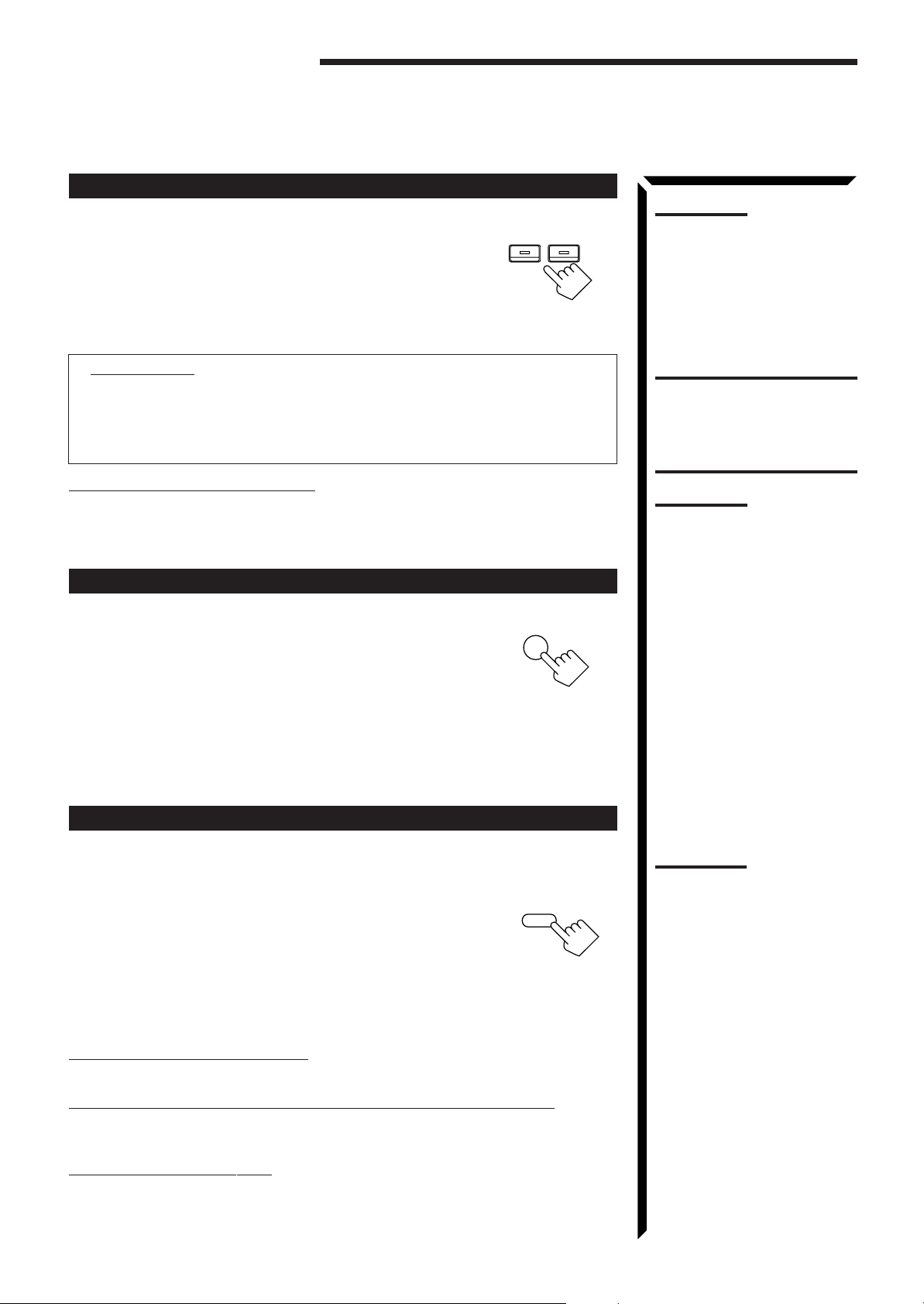
Press and hold SOUND SELECT/INPUT ATT until “INPUT
only
:
SOUND SELECT
ATT ON” appears on the display.
The ATT indicator also lights up on the display.
INPUT ATT.
Each time you press and hold the button, the input attenuator mode
turns on (“INPUT ATT ON”) and off (“INPUT NORMAL”).
You can set input attenuator mode separately for each source.
Adjusting the Subwoofer Output Level
You can adjust the subwoofer output level if you have selected “YES” for the
“SUBWOOFER” (see page 18).
Once it has been adjusted, the receiver memorizes the adjustment.
On the front panel:
1. Press BALANCE/SURROUND ADJUST repeatedly until
“SUBWFR LEVEL” appears on the display.
The display changes to show the current setting.
BALANCE/SURROUND
ADJUST
Notes:
• This function is available only
for the sources connected
using the analog terminals.
• This function takes effect only
when the DSP mode is in use.
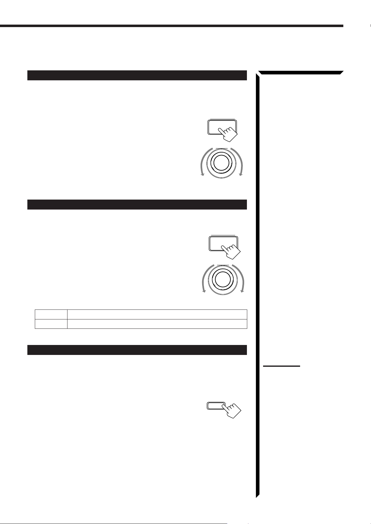
2. Turn MULTI JOG to adjust the subwoofer output level (–
MULTI JOG
10 dB to +10 dB), while the indication of the previous step is
still on the display.
From the remote control:
SOUND
1. Press SOUND.
10 keys are activated for sound adjustments.
SUBWOOFER
–+
2. Press SUBWOOFER +/– to adjust the subwoofer output
level (–10 dB to +10 dB).
0
FM MODE/
MUTE
+10
100+
Recording a Source
You can record any source playing through the receiver to the cassette deck or the MD
recorder connected to the TAPE/MD jacks and the VCRs connected to the VCR1 and
VCR2 jacks at the same time.
While recording, you can listen to the selected sound source at whatever sound level
you like, without affecting the sound levels of the recording.
Note:
The output volume level and
SEA modes cannot affect the
recording.
IMPORTANT:
When recording the digital
source, turn off the DSP mode.
16
Page 20
Basic Settings
SOURCE SELECTOR
SOURCE SELECTOR
DIGITAL INPUT
DIGITAL/
ANALOG
INPUT
Some of the following settings are required after connecting and positioning your speakers in your listening
room, while others will make operations easier.
IMPORTANT:
AUDIO/
TV/VCR
CATV
DBS
Changing the Source Name
When using the Remote Control, check to see if its remote control
mode selector is set to the correct position:
To operate this receiver, set it to “AUDIO/TV/VCR” (except when
selecting the DBS tuner as the source).
If you have connected an MD recorder to the TAPE/MD jacks or the DBS tuner to the
TV SOUND/DBS jacks on the rear panel, change the source name shown on the display
when you select the MD recorder or DBS tuner as the source.
On the front panel
only
:
1. When changing the source name from “TAPE” to “MD”:
• Turn SOURCE SELECTOR until “TAPE” appears.
When changing the source name from “TV SOUND” to
“DBS”:
• Turn SOURCE SELECTOR until “TV SOUND”
appears.
LOUDNESS
SOURCE NAME
2. Press and hold SOURCE NAME until “ASSGN.
MD” or “ASSGN. DBS” appears on the display.
To change the source names to “TAPE” or “TV SOUND,” repeat the same procedure
above (in step 1, select “MD” or “DBS” then press and hold SOURCE NAME).
Selecting the Input Mode
When you have connected some components such as CD player, MD recorder, DVD
player and the DBS tuner using digital terminals (see page 11), you need to change the
input mode for these components to the digital input.
On the front panel:
1. Turn SOURCE SELECTOR until the source (CD, MD,
DBS, or DVD) for which you want to change the input
mode from analog input to digital input.
Note:
Without changing the source
name, you can still use the
connected components.
However, there may be some
inconvenience.
– “TAPE” or “TV SOUND” will
appear on the display when
you select the MD recorder or
DBS tuner.
– You cannot use the digital
input (see below) for the MD
recorder and the DBS tuner.
– You cannot use the COMPU
LINK remote control system
(see page 48) to operate the
MD recorder.
Note:
Once you have set the digital
input for these components, it is
always used every time you
select these components as the
source.
2. Press DIGITAL INPUT to change the input mode.
Each time you press the button, the input mode alternates
between the digital input and analog input.
From the remote control:
1. Press the source selecting button (CD, TAPE/MD, TV/DBS,
or DVD) for which you want to change the input mode from
analog input to digital input.
2. Press DIGITAL/ANALOG INPUT to change the input
mode.
Each time you press the button, the input mode alternates
between the digital input and analog input.
17
VCR 1 VCR 2 VIDEO
DVD
CD TAPE/MD PHONO TV/DBS
AM FM
Page 21
SETTING
Adjusting the Front Speaker Output Balance
If the sounds you hear from the front right and left speakers are unequal, you can adjust
the speaker output balance.
On the front panel
only
:
1. Press BALANCE/SURROUND ADJUST repeatedly until
“L/R BALANCE” appears on the display.
The display changes to show the current setting.
2. Turn MULTI JOG to adjust the balance, while the
indication of the previous step is still on the display.
• Turning it clockwise decreases the left channel output.
• Turning it counterclockwise decreases the right channel
output.
Setting the Subwoofer Information
Register whether or not you have connected a subwoofer.
On the front panel
only
:
1. Press SETTING repeatedly until “SUBWOOFER” appears
on the display.
The display changes to show the current setting.
2. Turn MULTI JOG to register whether you have connected
a subwoofer or not, while the indication of the previous
step is still on the display.
As you turn it, the subwoofer setting alternates between
“YES” and “NO.”
BALANCE/SURROUND
ADJUST
MULTI JOG
MULTI JOG
YES Select this when you use a subwoofer.
NO Select this when you do not use a subwoofer.
Listening at Low Volume (Loudness)
Human ears are not sensitive to bass at low volume. To compensate for this, the
loudness function automatically boosts the bass level as you lower the volume.
On the front panel
Press LOUDNESS/SOURCE NAME briefly to select the
only
:
LOUDNESS
loudness function.
Each time you press the button, the loudness function turns on
SOURCE NAME
(“LOUDNESS ON”) and off (“LOUDNESS OFF”).
• Select “LOUDNESS ON” to activate the loudness function.
The LOUDNESS indicator lights up on the display.
• Select “LOUDNESS OFF” to cancel it.
The indicator goes off.
Note:
The loudness function affects
the front speaker sounds only.
18
Page 22
Basic Settings
SETTING
SETTING
Digital Input (DIGITAL IN) Terminal Setting
When you use the digital input terminals, you have to register what components are
connected to which terminals (DIGITAL IN 1/2/3).
On the front panel
only
:
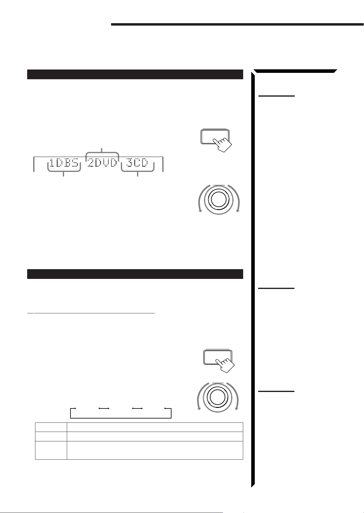
1. Press SETTING repeatedly until “DIGITAL IN”
appears on the display.
The display changes to show the current setting.
DIGITAL 2 terminal setting
DIGITAL 1 terminal setting
DIGITAL 3 terminal setting
MULTI JOG
2. Turn MULTI JOG to select the appropriate digital terminal
setting, while the indication of the previous step is still on
the display.
As you turn it, the display changes to show the following:
“ 1 DBS 2 DVD 3 CD “ 1 MD 2 DVD 3 CD “ 1 MD 2 DBS 3 CD
“ 1 MD 2 DBS 3 DVD “ 1 CD 2 DVD 3 MD “ 1 CD 2 DBS 3 MD
“ 1 CD 2 DBS 3 DVD “ 1 DVD 2 CD 3 MD “ 1 DVD 2 DBS 3 MD
“ 1 DVD 2 DBS 3 CD “ 1DBS 2 CD 3 MD “ DBS 2 DVD 3 MD
“ (back to the beginning)
Note:
When shipped from the factory,
the DIGITAL IN terminals can be
used as the digital input for the
following components.
• DIGITAL 1 (coaxial): For DBS
tuner
• DIGITAL 2 (optical): For DVD
player
• DIGITAL 3 (optical): For CD
player
Setting the Speakers for the DSP Modes
To obtain the best possible surround sound of the DSP modes, you have to register the
information about the speakers arrangement after all connections are completed.
Front, Center, and Rear Speaker Setting
Register the sizes of the other speakers.
On the front panel
only
:
1. Press SETTING repeatedly until “FRONT SPK” (Front
Speaker), “CENTER SPK” (Center Speaker) or “REAR
SPK” (Rear Speaker) appears on the display.
The display changes to show the current setting.
2. Turn MULTI JOG to select the appropriate item about
your front, center and rear speakers, while the indication of
MULTI JOG
the previous step is still on the display.
As you turn it, the display changes to show the following:
LARGE SMALL NONE
LARGE Select this when the speaker size is relatively large.
SMALL Select this when the speaker size is relatively small.
NONE Select this when you have not connected a speaker. (Not selectable
for the front speakers)
Note:
When you change your
speakers, you need to register
the information about the
speakers again.
Notes:
• If the size of the cone speaker
unit built in your speaker is
greater than 4 3/4 inches (12
cm ), select “LARGE,” and if it
is smaller than 4 3/4 inches (12
cm ), select “SMALL.”
• If you have selected “NO” for
the subwoofer setting, you
can only select “LARGE” for
the front speaker setting.
19
Page 23
Center Delay Time Setting
SETTING
SETTING
SETTING
Register the delay time of the sound from the center speaker, comparing that of the
sound from the front speakers.
If the distance from your listening point to the center speaker is equal to that to the front
speakers, select 0 msec. As the distance to the center speaker becomes shorter, increase
the delay time.
On the front panel
only
:
1. Press SETTING repeatedly until “CENTER DELAY”
appears on the display.
The display changes to show the current setting.
2. Turn MULTI JOG to select the delay time of the center
MULTI JOG
speaker output, while the indication of the previous step is
still on the display.
• Turn it clockwise to increase the delay time from 0 msec
(“C. DELAY 0ms”) to 5 msec (“C. DELAY 5ms”).
• Turn it counterclockwise to decrease the delay time from
5 msec (“C. DELAY 5ms”) to 0 msec (“C. DELAY
0ms”).
Rear Delay Time Setting
Register the delay time of the sound from the rear speakers, comparing that of the sound
from the front speakers.
If the distance from your listening point to the rear speakers is equal to that to the front
speakers, select 0 msec. As the distance to the rear speakers becomes shorter, increase
the delay time.
On the front panel
only
:
1. Press SETTING repeatedly until “REAR DELAY” appears
on the display.
The display changes to show the current setting.
Note:
1 msec increase (or decrease)
in delay time corresponds to 11
13
/16 inches (30 cm) decrease (or
increase) in distance.
Notes:
• 1 msec increase (or
decrease) in delay time
corresponds to 11 13/16 inches
(30 cm) decrease (or
increase) in distance.
• It is recommended that the
rear delay time for Dolby
Digital be set to 5 msec.
2. Turn MULTI JOG to select the delay time of the rear
MULTI JOG
speaker output, while the indication of the previous step is
still on the display.
• Turn it clockwise to increase the delay time from 0 msec
(“R. DELAY 0ms”) to 15 msec (“R. DELAY 15ms”).
• Turn it counterclockwise to decrease the delay time from
15 msec (“R. DELAY 15ms”) to 0 msec (“R. DELAY
0ms”).
Crossover Frequency Setting
Small speaker cannot reproduce the bass sound very well. So, if you have used a small
speaker any for the front, center, or rear channels, this receiver automatically reallocate
the bass elements, originally assigned to the channel for which you have connected the
small speaker, to another channel (for which you have connected the large speaker).
To use this function properly, you need to set this crossover frequency level according to
the size of the small speaker connected.
On the front panel
only
:
1. Press SETTING repeatedly until “CROSSOVER FRQ”
(Crossover Frequency) appears on the display.
The display changes to show the current setting.
Note:
This function takes effect only
when playing back a sources
using the Dolby Digital.
However, if you have selected
“LARGE” for all speakers (see
page 19), this function will not
take effect.
20
Page 24

Basic Settings
SETTING
SETTING
2. Turn MULTI JOG to select the crossover frequency level
according to the size of the small speaker connected, while
the indication of the previous step is still on the display.
As you turn it, the display changes to show the following:
CROSS: 80Hz CROSS:100Hz CROSS:120Hz
CROSS: 80Hz Select this when the cone speaker unit built in the speaker is
about 4 3/4 inches (12 cm).
CROSS:100Hz Select this when the cone speaker unit built in the speaker is
about 3 15/16 inches (10 cm).
CROSS:120Hz Select this when the cone speaker unit built in the speaker is
about 3 3/16 inches (8 cm).
Low Frequency Effect Attenuator Setting
If the bass sound is distorted while playing back a source using Dolby Digital, follow
the procedure below.
On the front panel
only
:
1. Press SETTING repeatedly until “LFE ATT” (Low
Frequency Effect Attenuator) appears on the display.
The display changes to show the current setting.
2. Turn MULTI JOG to select the low frequency effect
MULTI JOG
attenuator level, while the indication of the previous step is
still on the display.
As you turn it, the display changes to show the following:
LFE ATT: 0dB LFE ATT:10dB
LFE A TT : 0dB: Normally select this.
LFE A TT :10dB: Select this when the bass sound is distorted.
Dynamic Range Compression Setting
You can compress the dynamic range (difference between maximum sound and
minimum sound) of the reproduced sound. This is useful when enjoying surround sound
at night.
On the front panel
only
:
1. Press SETTING repeatedly until “D. RANGE COMP.”
(Dynamic Range Compression) appears on the display.
The display changes to show the current setting.
Note:
This function takes effect only
when playing back a sources
using the Dolby Digital.
Note:
This function takes effect only
when playing back a sources
using the Dolby Digital.
2. Turn MULTI JOG to select the appropriate item about the
compression level, while the indication of the previous step
is still on the display.
As you turn it, the display changes to show the following:
COMP.: OFF COMP.: MID COMP.: MAX
COMP.: OFF Select this when you want to enjoy surround with its full
dynamic range. (No effect applied.)
COMP.: MID Select this when you want to reduce the dynamic range a
little. (Factory setting).
COMP.: MAX Select this when you want to apply the compression effect
fully. (Useful at night).
21
MULTI JOG
Page 25

One Touch Operation
This receiver can memorize the optimum sound settings for each playing source.
About the One Touch Operation
JVC’s One Touch Operation function is used to assign and store different sound settings
for each different playing source. By using this function, you do not have to change the
settings every time you change the source. The stored settings for the newly selected
source are automatically recalled.
The following can be stored for each source:
• Volume level (see page 14)
• Input attenuator mode (see page 16)
• Subwoofer output level (see page 16)
• Input mode (see page 17)
• Balance (see page 18)
• Loudness (see page 18)
• SEA modes (see page 26)
• DSP modes
– 3D-PHONIC mode settings (see page 29)
– DAP mode settings (see page 32)
– Surround mode settings (see page 34 and 37)
Using the One Touch Operation
On the front panel
To store the sound settings
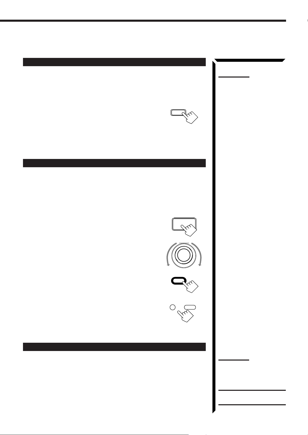
1. Press ONE TOUCH OPERATION.
The ONE TOUCH OPERATION lamp lights up, then the
previously memorized settings are recalled.
only
:
ONE TOUCH OPERATION
Note:
If the source is FM or AM, you
can assign a different setting for
each band.
2. Adjust the sound using the functions listed above.
The newly adjusted settings are memorized.
To recall the sound settings
With the ONE TOUCH OPERATION lamp lit, the settings for the
currently selected source is recalled when the source is selected.
To cancel the One Touch Operation function
Press ONE TOUCH OPERATION so that the lamp goes off.
(Even though the One Touch Operation function is canceled, the
recalled sound effects remain active.)
ONE TOUCH OPERATION
22
Page 26

Receiving Radio Broadcasts
FM/AM TUNING
You can browse through all the stations or use the preset function to go immediately to a particular
station.
IMPORTANT:
AUDIO/
TV/VCR
CATV
DBS
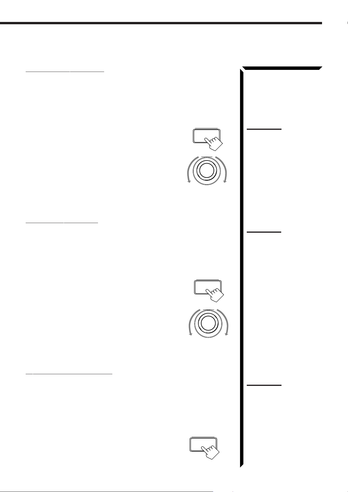
Tuning in Stations Manually
On the front panel:
1. Press FM/AM TUNING to select the band.
Each time you press the button, the band alternates between
FM and AM.
2. Turn MULTI JOG until you find the frequency you
want.
• Turning it clockwise increases the frequency.
• Turning it counterclockwise decreases the frequency.
From the remote control:
1. Press FM or AM to select the band.
When using the Remote Control, check to see if its remote control
mode selector is set to the correct position:
To operate this receiver, set it to “AUDIO/TV/VCR” (except when
selecting the DBS tuner as the source).
MULTI JOG
AM FM
Notes:
• When you turn MULTI JOG
quickly or hold the TUNING
UP or TUNING DOWN in step
2, the frequency keeps
changing until a station is
tuned in.
• When a station of sufficient
signal strength is tuned in, the
TUNED indicator lights up on
the display.
When an FM stereo program
is received, the STEREO
indicator also lights up.
2. Press TUNING DOWN or TUNING UP repeatedly
until you find the frequency you want.
/REW
DOWN TUNING
FF/
Using Preset Tuning
Once a station is assigned to a channel number, the station can be quickly tuned. You
can preset up to 40 stations at random.
To store the preset stations
On the front panel
only
:
1. Tune in the station you want to preset (see above).
If you want to store the FM reception mode for this station, select the FM reception
mode you want. See page 24 for details.
2. Press TUNER/SEA MEMORY.
TUNER/SEA MEMORY
“CH-” appears and the channel number position starts flashing
on the display for about 5 seconds.
MULTI JOG
3. Turn MULTI JOG to select a channel number while
the channel number position is flashing.
4. Press TUNER/SEA MEMORY again while the
selected channel number is flashing on the display.
The selected channel number stops flashing.
TUNER/SEA MEMORY
The station is assigned to the selected channel number.
UP
Note:
You can use the 10 keys on the
remote control to select the
preset number. When using the
10 keys, be sure that they are
activated for tuner, not for the
CD and others. (See page 58.)
23
Page 27

5. Repeat steps 1 to 4 until you store all the stations you
TUNER PRESET
want.
To erase a stored preset station
Storing a new station on a used number erases the previously stored one.
To tune in a preset station
On the front panel:
1. Press TUNER PRESET .
2. Turn MULTI JOG to select a preset channel.
MULTI JOG
From the remote control:
1. Press FM or AM.
2. Press 10 keys to select a preset channel number.
• For channel number 5, press 5.
• For channel number 15, press +10 then 5.
• For channel number 20, press +10 then 10.
• For channel number 30, press +10, +10, then 10.
Selecting the FM Reception Mode
When an FM stereo broadcast is hard to receive or noisy, set the FM reception mode to
“MONO.” (When shipped from the factory, this mode has been set to “AUTO.”)
You can change the FM reception mode while receiving an FM broadcast.
Press FM MODE on the front panel or FM MODE/
FM MODE
MUTE on the remote control.
Each time you press the button, the FM reception mode
alternates between “AUTO” and “MONO.”
AUTO: When a program is broadcast in stereo, you will hear stereo sound;
when in monaural, you will hear monaural sounds. This mode is
also useful to suppress static noise between stations.
The MUTE AUTO indicator lights up on the display.
MONO: Reception will be improved although you will lose the stereo effect.
In this mode, you will hear noise while tuning into the stations.
The MUTE AUTO indicator goes off on the display.
AM FM
CNTR TONE CNTR
1 2 3
TEST REAR · L
456
EFFECT
7/P8
SEA MODE
10
RETURN FM MODE/
–+
–+
ENTER
–+
REAR · R
9
SUBWOOFER
–+
0
MUTE
FM MODE/
MUTE
SUBWOOFER
–
0
+10
100+
MENU
Note:
When you use the 10 keys on
the remote control, be sure that
they are activated for tuner, not
for the CD and others. (See
page 58.)
Notes:
• You can store the FM
reception mode for each
preset station.
• When using the FM MODE/
MUTE button, be sure that the
10 keys are activated for
tuner, not for the CD and
others. (See page 58.)
24
Page 28

Receiving Radio Broadcasts
TUNER PRESET
TUNER PRESET
Assigning Names to Preset Stations
You can assign a name of up to four characters to each preset station. When a preset
station is tuned in, its assigned name will appear on the display.
On the front panel
only
:
1. Tune in a preset station.
See page 24 for details.
2. Press TUNER/SEA MEMORY.
The preset channel number starts flashing for about 5 seconds.
CH–
3. Press TUNER PRESET, while the preset channel number is
flashing.
The first character position starts flashing.
CH–
VOLUME
4. Turn MULTI JOG to select the first character, while
the first character position is flashing..
You can use characters listed below.
CH–
TUNER/SEA MEMORY
MULTI JOG
Note:
If you turn MULTI JOG while the
preset channel number is
flashing, you can change
the preset channel number.
Note on step 3 to 7:
You cannot select any entry after
the indication on the display
stops flashing.
In this case, repeat the
procedure from step 2 again.
5. Press TUNER PRESET, while a character you want is
flashing.
The next (or previous) character position starts flashing.
CH–
6. Repeat steps 4 and 5 to enter up to four characters.
7. Press TUNER/SEA MEMORY while the last selected
character is flashing after you have assigned a name.
To erase the input characters
Insert spaces using the same procedure described above.
Available characters
Space
CBADEGFHIJKLMNO
SRQTUWVX
MULTI JOG
Z01234P
Y
TUNER/SEA MEMORY
87695
25
Page 29

Using the SEA Modes
SEA MODE
10
SEA MODE
RETURN
The SEA (Sound Effect Amplifier) modes give you control of the way your music sounds.
IMPORTANT:
AUDIO/
TV/VCR
CATV
DBS
When using the Remote Control, check to see if its remote control
mode selector is set to the correct position:
To operate this receiver, set it to “AUDIO/TV/VCR” (except when
selecting the DBS tuner as the source).
Selecting Your Favorite SEA Mode
On the front panel:
1. Press SEA MODE.
The display changes to show the current setting.
2. Turn MULTI JOG until the mode you want appears on the
display, while the indication of the previous step is still on
the display.
As you turn it, the SEA mode changes as follows:
SEA ROCK SEA MUSICAL SEA MOVIE
SEA USERMODESEA OFF
SEA COUNTRY
SEA JAZZ
SEA ROCK: Gives a heavy sound. Both high and low frequencies are
boosted.
SEA MUSICAL: Enhance the mid-frequency range, which the human voice is
mostly made up of.
SEA MOVIE: Adds breadth to sounds so you feel like you are in a movie
theater.
SEA COUNTRY: Enhances the high-frequency range so that instruments such
as the violin and banjo are emphasized.
SEA JAZZ: Gives a feeling of a live atmosphere. Good for acoustic music.
SEA USERMODE: Your original SEA adjustment (see page 27).
SEA OFF: No SEA mode is applied (see below).
MULTI JOG
Notes:
• The SEA modes cannot be
used for recording.
• When the SEA mode is turned
on, the SEA indicator lights up
on the display.
• When the SEA mode is used
with the DAP mode (see page
32), sounds may be distorted.
If this happens, turn off the
DAP mode or decrease the
effect level of the DAP mode.
To cancel the SEA mode
Turn MULTI JOG until “SEA OFF” appears in step 2 above.
The SEA indicator goes off from the display.
From the remote control:
1. Press SOUND.
10 keys are activated for sound adjustments.
2. Press SEA MODE repeatedly until the SEA mode you want
appears on the display.
Each time you press the button, the SEA mode changes
as follows:
SEA ROCK SEA MUSICAL SEA MOVIE
SEA USERMODESEA OFF
To cancel the SEA mode
Press SEA MODE until “SEA OFF” appears in step 2 above.
The SEA indicator goes off from the display.
SEA COUNTRY
SEA JAZZ
SOUND
Note:
When the SEA mode is turned
on, the SEA indicator lights up
on the display.
26
Page 30

SEA ADJUST
Using the SEA Modes
Creating Your Own SEA Mode
You can adjust and store your own SEA adjustment into memory (SEA USERMODE).
On the front panel
only
:
If you do not want to store your adjustment, but rather want to adjust the SEA
temporarily, skip step 4 below.
1. Press SEA ADJUST repeatedly until the frequency range
(100Hz, 1kHz or 10kHz) you want appears on the display.
S E A
FR
100 1k 10k
S E A
FR
100 1k 10k
VOLUME
VOLUME
2. Turn MULTI JOG to adjust the SEA level of the selected
frequency range, while the indication of the previous step is
still on the display.
• Turning it clockwise increases the level.
• Turning it counterclockwise decreases the level.
MULTI JOG
This FR means this adjustment can be
applied to the front speakers only
S E A
100 1k 10k
FR
3. Repeat step 1 and 2 to adjust other frequency ranges if
necessary.
4. Press TUNER/SEA MEMORY, while the indication of the
TUNER/SEA MEMORY
previous step is still on the display.
Your adjustment is stored into the SEA USERMODE.
To recall your own SEA adjustment
See page 26.
To erase a stored adjustment
Storing a new adjustment into SEA USERMODE erases the previously stored one.
27
Page 31

Using the DSP Modes
The built-in Surround Processor provides three types of the DSP (Digital Signal Processor) mode — 3DPHONIC mode, DAP (Digital Acoustic Processor) mode and Surround mode (Dolby Digital, Dolby Pro Logic
and JVC’s Theater Surround.)
On the 3D-PHONIC mode
The 3D-PHONIC mode gives you such a
nearly surround effect as it is reproduced
through the Dolby Surround decoder, which
is widely used to reproduce sounds with a
feeling of movement like those experienced
in movie theaters. The 3D-PHONIC mode is
the result of research on sound localization
technology carried out at JVC for many
years and makes it possible to reproduce the
surround sound with only two front
speakers.
On the DAP mode
The sound heard in a concert hall or club
consists of direct sound and indirect sound
— early reflections and reflections from
behind. Direct sounds reach the listener
directly without any reflection. On the other
hand, indirect sounds are delayed by the
distances of the ceiling and walls. These
direct sounds and indirect sounds are the
most important elements of the acoustic
surround effects. The DAP mode can create
these important elements, and gives you a
real “being there” feeling.
Early reflections
Direct sounds
Reflections from
behind
Notes:
• The DSP modes have no
effect on monaural sources.
• You can not use the two types
of the DSP modes at the same
time.
IMPORTANT:
When recording the digital
source, turn off the DSP mode.
On Surround mode
With this receiver, you can use two types of
the surround mode.
Dolby Surround (Dolby Digital and
Dolby Pro Logic)
Used to watch the soundtracks of software
encoded with Dolby Digital (bearing the
mark
DIGITAL
(bearing the mark
) or with Dolby Surround
DOLBY SURROUND
).
Dolby Digital and Dolby Pro Logic can be
selected automatically according to
software played back.
JVC’s Theater Surround
In order to reproduce a more realistic sound field in your listening room while playing
soundtracks of software encoded with Dolby Digital (bearing the mark
with Dolby Surround (bearing the mark
DOLBY SURROUND
), Theater Surround has been
DIGITAL
) or
designed to create a real “being there” feeling.
Note:
To enjoy the software encoded
with Dolby Digital, you must
connect the source component
using the digital terminal on the
rear of this receiver.
Manufactured under license
from Dolby Laboratories.
“Dolby,” “Pro Logic,” and the
double-D symbol are trademarks
of Dolby Laboratories.
Confidential Unpublished Works.
©1992–1997 Dolby
Laboratories, Inc. All rights
reserved.
28
Page 32

Using the DSP Modes
DSP MODE
IMPORTANT:
AUDIO/
TV/VCR
CATV
DBS
Using the 3D-PHONIC Modes
When using the Remote Control, check to see if its remote control
mode selector is set to the correct position:
To operate this receiver, set it to “AUDIO/TV/VCR” (except when
selecting the DBS tuner as the source).
When using the 3D-PHONIC modes, you need only two front speakers to reproduce the
soundtracks of software encoded with Dolby Digital (bearing the mark
with Dolby Surround (bearing the mark
DOLBY SURROUND
).
DIGITAL
) or
On the front panel:
1. Select and play the source encoded with Dolby Digital (bearing the mark
DIGITAL
) or with Dolby Surround (bearing the mark
• When you play back the source encoded with Dolby Digital and select the digital
input for that source, the Ÿ DIGITAL indicator lights up on the display.
2. Press DSP MODE.
The current DSP mode appears on the display.
3. Turn MULTI JOG until the mode — 3D ACTION (or 3D
DIGITAL), 3D DRAMA, or 3D THEATER — you want
appears on the display, while the indication of the previous
step is still on the display.
As you turn it, the DSP modes change as follows (the 3DPHONIC and DSP indicators also light up on the display):
When the digital input is selected to play the source encoded with Dolby
Digital:
DIG-THEATER
DSP OFF
HEADPHONE
3D DIGITAL
For other sources:
LIVE CLUBTHEATER
DANCE CLUB
DSP OFF
3D THEATER
3D DRAMA
3D ACTION
3D ACTION: Best for action and war movies — where the action is fast and
explosive.
3D DRAMA: Best for dramas and romantic movies — where the action is
slow and soft.
3D THEA TER: Reproduces the sound field of a theater.
3D DIGITAL: Reproduces multi-sound source encoded with Dolby Digital.
DSP OFF
:
No DSP mode is applied.
DOLBY SURROUND
HALL
PAVILION
HEADPHONE
).
MULTI JOG
Notes:
• To enjoy the software
encoded with Dolby Digital,
you must connect the source
component using the digital
terminal on the rear of this
receiver.
• The 3D-PHONIC mode is not
used with the other DSP
modes such as the DAP
mode and the Surround
mode. When the 3D-PHONIC
mode is turned on, the other
DSP mode, if used, will be
turned off.
Notes on the indications:
• The indicator of the selected
DSP mode also lights up on
the display while selecting.
• The PRO LOGIC indicator
lights up when the Dolby Pro
Logic decoder built in this
receiver is activated.
• The Dolby Pro Logic decoder
is used not only for the analog
sources but also for the
sources encoded with Dolby
Digital in the following cases:
– When only front channel
signals are encoded.
– When front channel and
monaural rear channel
signals are encoded.
While the Dolby Pro Logic is
activated for this type of Dolby
Digital source, the Ÿ DIGITAL
indicator goes off.
For the other modes, see pages 32 and 37.
If you need to make any adjustment, go to the following steps.
29
Page 33

4. Press BALANCE/SURROUND ADJUST repeatedly until
“DSP EFFECT” appears on the display.
The display changes to show the current setting.
5. Turn MULTI JOG to select the effect level, while the indication of
the previous step is still on the display.
As you turn it, the effect level changes as follows:
BALANCE/SURROUND
ADJUST
MULTI JOG
Note:
Once you have adjusted the 3DPHONIC modes, it is memorized
for each 3D-PHONIC mode.
DSP EFFECT 1 DSP EFFECT 2
DSP EFFECT 5
DSP EFFECT 4
DSP EFFECT 3
As the number increases, the selected 3D-PHONIC mode
becomes stronger.
To cancel the 3D-PHONIC mode
Turn MULTI JOG until “DSP OFF” appears in step 3.
The 3D-PHONIC and DSP indicators go off from the display.
30
Page 34

Using the DSP Modes
MODE
SURROUND
SOUND
From the remote control:
1. Select and play the source encoded with Dolby Digital (bearing the mark
DIGITAL
) or with Dolby Surround (bearing the mark
• When you play back the source encoded with Dolby Digital and select the digital
input for that source, the Ÿ DIGITAL indicator lights up on the display.
2. Press SURROUND MODE repeatedly until the mode — 3D
ACTION (or 3D DIGITAL), 3D DRAMA, or 3D THEATER
— you want appears on the display.
Each time you press the button, the DSP modes change as
follows (the 3D-PHONIC and DSP indicators also light up
on the display):
When the digital input is selected to play the source encoded with Dolby
Digital:
DOLBY DIGITAL
OFF
3D DIGITAL
DIG-THEATER
HEADPHONE
For other sources:
PRO LOGIC
OFF
3D THEATER
THEATER
3D DRAMA
LIVE CLUB
3D ACTION
3. Press SOUND.
10 keys are activated for sound adjustments.
4. Press EFFECT to select the effect level.
Each time you press the button, the effect level changes as follows:
DSP EFFECT 1 DSP EFFECT 2
DSP EFFECT 5
DSP EFFECT 4
DSP EFFECT 3
As the number increases, the selected 3D-PHONIC mode becomes
stronger.
DOLBY SURROUND
DANCE CLUB
HEADPHONE
).
PAVILION
EFFECT
7
HALL
Note:
The 3D-PHONIC mode is not
used with the other DSP modes
such as the DAP mode and the
Surround mode. When the 3DPHONIC mode is turned on, the
other DSP mode, if used, will be
turned off.
Notes on the indications:
• The indicator of the selected
DSP mode also lights up on
the display while selecting.
• The PRO LOGIC indicator
lights up when the Dolby Pro
Logic decoder built in this
receiver is activated.
• The Dolby Pro Logic decoder
is used not only for the analog
sources but also for the
sources encoded with Dolby
Digital in the following cases:
– When only front channel
signals are encoded.
– When front channel and
monaural rear channel
signals are encoded.
While the Dolby Pro Logic is
activated for this type of Dolby
Digital source, the Ÿ DIGITAL
indicator goes off.
To cancel the 3D-PHONIC mode
Press SURROUND MODE repeatedly until “OFF” appears.
The 3D-PHONIC and DSP indicators go off from the display.
31
Note:
Once you have adjusted the 3DPHONIC modes, it is memorized
for each 3D-PHONIC mode.
Page 35

Using the DAP Modes
You can use five DAP modes — “Live Club, Dance Club, Hall, Pavilion, and
Headphones” for any source.
Among the DAP modes, “Headphones” is very special. It can create the same stereo
sound as you listen through the speakers off air while listening to a source using
headphones. So, you can feel as if you were not using the headphones and listening to
music in a room.
If the digital input is selected to play the source encoded with Dolby Digital, you can
only select “Headphones.”
On the front panel:
DSP MODE
1. Press DSP MODE.
The current DSP mode appears on the display.
2. Turn MULTI JOG until the mode (LIVE CLUB, DANCE
CLUB, HALL, PAVILION, or HEADPHONE) you want
MULTI JOG
appears on the display, while the indication of the previous
step is still on the display.
The DSP indicator also lights up on the display.
As you turn it, the DSP modes change as follows:
HALL
PAVILION
HEADPHONE
DSP OFF
3D THEATER
LIVE CLUBTHEATER
3D DRAMA
DANCE CLUB
3D ACTION
When the digital input is selected to play the source encoded with Dolby
Digital:
DIG-THEATER
DSP OFF
HEADPHONE
3D DIGITAL
Notes:
• The DAP mode is not used
with the other DSP modes
such as the 3D-PHONIC
mode and the Surround
mode. When the DAP mode
is turned on, the other DSP
mode, if used, will be turned
off.
• When the DAP mode is used
with the SEA mode (see page
26), sounds may be distorted.
If this happens, turn off the
SEA mode.
Note:
The indicator of the selected
DSP mode also lights up on the
display while selecting.
LIVE CLUB: Gives the feeling of a live music club with a low ceiling.
DANCE CLUB: Gives a throbbing bass beat.
HALL: Gives clear vocal and the feeling of a concert hall.
PAVILION: Gives the spacious feeling of a pavilion with a high ceiling.
HEADPHONE:
DSP OFF
:
Gives a spacious stereo effect when listening with headphones.
No DSP mode is applied.
For the other modes, see pages 29 and 37.
If you need to make any adjustment, go to the following steps.
3. Adjust the speaker output levels as follows.
BALANCE/SURROUND
1) Press BALANCE/SURROUND ADJUST repeatedly
until one of the indications appears on the display.
“REAR L LEVEL”: To adjust the left speaker level.
“REAR R LEVEL”: To adjust the right speaker level.
2) Turn MULTI JOG to adjust the selected speaker output
level (from –10 dB to +10 dB), while the indication of the
previous step is still on the display.
3) Repeat 1) and 2) to adjust the other speaker output
levels.
Continued to the next page.
ADJUST
MULTI JOG
Note:
When you select
“HEADPHONE,” you cannot go
to the following steps. No
adjustments can be made for
HEADPHONE.”
Note:
You cannot adjust the rear
speaker levels when “REAR
SPK” is set to “NONE” (see
page 19).
32
Page 36

Using the DSP Modes
MODE
SURROUND
SOUND
REAR · R
–+
89
4. Adjust the effect level.
BALANCE/SURROUND
1) Press BALANCE/SURROUND ADJUST repeatedly
until “DSP EFFECT” appears on the display.
2) Turn MULTI JOG to select the effect level, while the
indication of the previous step is still on the display.
As you turn it, the effect level changes as follows:
DSP EFFECT 1 DSP EFFECT 2
DSP EFFECT 5
DSP EFFECT 4
DSP EFFECT 3
As the number increases, the selected DAP mode
becomes stronger.
To cancel the DAP mode
Turn MULTI JOG until “DSP OFF” appears in step 2.
The DSP indicator goes off from the display.
From the remote control:
1. Press SURROUND MODE repeatedly until the mode you
want appears on the display.
The DSP indicator also lights up on the display.
Each time you press the button, the DSP modes change as follows (the indicator
of the selected DSP mode also lights up on the display):
PRO LOGIC
OFF
3D THEATER
THEATER
3D DRAMA
LIVE CLUB
3D ACTION
When the digital input is selected to play the source encoded with Dolby
Digital:
DOLBY DIGITAL
OFF
3D DIGITAL
DIG-THEATER
HEADPHONE
DANCE CLUB
HEADPHONE
ADJUST
MULTI JOG
HALL
PAVILION
Note:
Once you have adjusted the
DAP modes, the adjustment is
memorized for each DAP mode.
Note:
The DAP mode is not used with
the other DSP modes such as
the 3D-PHONIC mode and the
Surround mode. When the DAP
mode is turned on, the other
DSP mode, if used, will be
turned off.
Note:
When you select
“HEADPHONE,” you cannot go
to the following steps. No
adjustments can be made for
“HEADPHONE.”
If you need to make any adjustment, go to the following steps.
2. Press SOUND.
10 keys are activated for sound adjustments.
3. Adjust the speaker output levels as follows:
• To adjust the left rear speaker level, press REAR•L +/–.
• To adjust the right rear speaker level, press REAR•R +/–.
4. Press EFFECT to select the effect level.
Each time you press the button, the effect level changes as
follows:
As the number increases, the selected DAP mode becomes
stronger.
To cancel the DAP mode
Press SURROUND MODE repeatedly until “OFF” appears.
The DSP indicator goes off from the display.
33
DSP EFFECT 1 DSP EFFECT 2
DSP EFFECT 5
DSP EFFECT 4
DSP EFFECT 3
REAR · L
–+
ENTER
56
EFFECT
7
/P
Note:
You cannot adjust the rear
speaker levels when “REAR
SPK” is set to “NONE” (see
page 19).
Note:
Once you have adjusted the
DAP modes, the adjustment is
memorized for each DAP mode.
Page 37

Using the Dolby Digital and Dolby Pro Logic Modes
MODE
SURROUND
Once you have adjusted the Dolby Digital and Dolby Pro Logic modes, this receiver
memorizes adjustment for each mode.
To activate the Dolby Digital and Dolby Pro Logic modes, follow the procedure below.
From the remote control:
1. Select and play the source encoded with Dolby Digital (bearing the mark
DIGITAL
) or with Dolby Surround (bearing the mark
• When you play back the source encoded with Dolby Digital and select the digital
input for that source, the Ÿ DIGITAL indicator lights up on the display.
2. Press SURROUND MODE repeatedly until “PRO LOGIC”
or “DOLBY DIGITAL” appears on the display.
Dolby Digital or Dolby Pro Logic is automatically selected
according to the source being played back.
When Dolby Pro Logic is selected, the lamp on the DOLBY SURROUND button
(on the front panel) lights red.
When Dolby Digital is selected, the lamp on the DOLBY SURROUND button (on
the front panel) lights green.
Each time you press the button, the DSP modes change as follows:
When the digital input is selected to play the source encoded with Dolby
Digital:
DOLBY DIGITAL
OFF
3D DIGITAL
DIG-THEATER
HEADPHONE
For other sources:
PRO LOGIC
OFF
3D THEATER
THEATER
3D DRAMA
LIVE CLUB
3D ACTION
If you need to make any adjustment, go to the following steps.
3. Press SOUND.
10 keys are activated for sound adjustments.
DOLBY SURROUND
DANCE CLUB
HEADPHONE
).
HALL
PAVILION
SOUND
Notes:
• To enjoy the software encoded
with Dolby Digital, you must
connect the source
component using the digital
terminal on the rear of this
receiver.
• When the signals come into
this receiver through the
analog connection from the
source component, “PRO
LOGIC” is automatically
selected.
• The Surround mode is not
used with the other DSP
modes such as the DAP mode
and 3D-PHONIC mode. When
the Surround mode is turned
on, the other DSP mode, if
used, will be turned off.
Notes on the indications:
• The PRO LOGIC indicator
lights up when the Dolby Pro
Logic decoder built in this
receiver is activated.
• The Dolby Pro Logic decoder
is used not only for the analog
sources but also for the
sources encoded with Dolby
Digital in the following cases:
– When only front channel
signals are encoded.
– When front channel and
monaural rear channel
signals are encoded.
While the Dolby Pro Logic is
activated for this type of Dolby
Digital source, the Ÿ DIGITAL
indicator goes off.
Continued to the next page.
34
Page 38

Using the DSP Modes
REAR · R
–+
89
CNTR TONE
1
4. Press TEST to start checking the speaker output balance.
“TEST TONE L” starts flashing on the display, and a test
TEST
4
tone comes out of the speakers in the following order:
TEST TONE L TEST TONE C TEST TONE R
(Left front speaker)
C
L
LS
R
RS
TEST TONE LS
(Left rear speaker)
The speaker indicators also light on the display while the test tone
comes out of the speakers.
L: Lights when the test tone comes out of the left front speaker.
C: Lights when the test tone comes out of the center speaker.
R: Lights when the test tone comes out of the right front speaker.
RS: Lights when the test tone comes out of the right rear speaker.
LS: Lights when the test tone comes out of the left rear speaker.
(Center speaker)
TEST TONE RS
(Right rear speaker)
(Right front speaker)
IMPORTANT:
• Output the test tone while playing back an audio source.
With the DVD digital input selected as the source, no test tone may come out while
no signal is input to this receiver.
• Test tone comes out even while playing back a source encoded with Dolby Digital. In
this case, the PRO LOGIC indicator lights up on the display.
CNTR
5. Adjust the speaker output levels as follows:
–+
23
MENU
• To adjust the center speaker level, press CNTR +/–.
• To adjust the left rear speaker level, press REAR•L +/–.
• To adjust the right rear speaker level, press REAR•R +/–.
6. Press TEST again to stop the test tone.
REAR · L
–+
ENTER
56
TEST
4
7. Press CNTR TONE to select the center tone level you want.
The center tone adjustment affects the mid-frequency
range, which the human voice is mostly made up of.
Each time you press the button, the display changes to
show the following:
SHARP1 SHARP2FLATSOFT2 SOFT1
Notes:
• No test tone comes out of the
center speakers when
“CENTER SPK” is set to
“NONE” (see page 19).
• No test tone comes out of the
rear speakers when “REAR
SPK” is set to “NONE” (see
page 19).
• If the TV is turned on and the
proper video input is selected
on the TV, the test tone
screen will appear on the TV.
Notes:
• You can adjust the speaker
output levels and center tone
without outputting the test
tone.
• You cannot adjust the center
speaker output level when
“CENTER SPK” is set to
“NONE” (see page 19).
• You cannot adjust the rear
speaker levels when “REAR
SPK” is set to “NONE” (see
page 19).
Note:
The center tone cannot be
adjusted when “CENTER SPK”
is set to “NONE” (see page 19).
Adjusted levels are also shown on the equalizer display.
To make the dialogue clearer, select “SHARP1” (little) or “SHARP2” (much).
To make the dialogue softer, select “SOFT1” (little) or “SOFT2” (much).
When “FLAT” is selected, no adjustment is applied.
To cancel the Surround mode
Press SURROUND MODE repeatedly until “OFF” appears.
35
S E A
100 1k 10k
CNTR
This CNTR means this adjustment can be
applied to the center speaker only.
(Example: When “FLAT” is selected.)
Page 39

On the front panel:
You can also use the buttons on the front panel to adjust the Dolby Digital and Dolby
Pro Logic modes. However, no test tone is available when using the buttons on the front
panel. So, make adjustments while listening to the sound of the source played back.
1. Select and play the source encoded with Dolby Digital (bearing the mark
DIGITAL
) or with Dolby Surround (bearing the mark
• When you play back the source encoded with Dolby Digital and select the digital
input for that source, the Ÿ DIGITAL indicator lights up on the display.
2. Press DOLBY SURROUND so that the lamp on the button
lights up.
“SURROUND ON” appears on the display.
Dolby Digital or Dolby Pro Logic is automatically selected
according to the source being played back.
When Dolby Pro Logic is selected, the lamp on the DOLBY SURROUND button
lights red.
When Dolby Digital is selected, the lamp on the DOLBY SURROUND button lights
green.
If you need to make any adjustment, go to the following steps.
3. Adjust the speaker output levels as follows.
1) Press BALANCE/SURROUND ADJUST repeatedly
until one of the indications appears on the display.
“CENTER LEVEL”: To adjust the center speaker level.
“REAR L LEVEL”: To adjust the left speaker level.
“REAR R LEVEL”: To adjust the right speaker level.
2) Turn MULTI JOG to adjust the selected speaker output
level (from –10 dB to +10 dB), while the indicator of the
previous step is still on the display.
3) Repeat 1) and 2) to adjust the other speaker output
levels.
4. Press BALANCE/SURROUND ADJUST repeatedly until
“CENTER TONE” appears on the display.
The display changes to show the current setting.
DOLBY SURROUND
DOLBY SURROUND
BALANCE/SURROUND
BALANCE/SURROUND
).
ADJUST
MULTI JOG
ADJUST
Notes:
• To enjoy the software encoded
with Dolby Digital, you must
connect the source
component using the digital
terminal on the rear of this
receiver.
• When the signals come into
this receiver through the
analog connection from the
source component, “PRO
LOGIC” is automatically
selected.
• The Surround mode is not
used with the other DSP
modes such as the DAP mode
and 3D-PHONIC mode. When
the Surround mode is turned
on, the other DSP mode, if
used, will be turned off.
Notes on the indications:
• The PRO LOGIC indicator
lights up when the Dolby Pro
Logic decoder built in this
receiver is activated.
• The Dolby Pro Logic decoder
is used not only for the analog
sources but also for the
sources encoded with Dolby
Digital in the following cases:
– When only front channel
signals are encoded.
– When front channel and
monaural rear channel
signals are encoded.
While the Dolby Pro Logic is
activated for this type of Dolby
Digital source, the Ÿ DIGITAL
indicator goes off.
5. Turn MULTI JOG to select the center tone level you want,
while the indication of the previous step is still on the
display.
The center tone adjustment affects the mid-frequency
range, which the human voice is mostly made up of.
As you turn it, the display changes to show the
following:
SHARP1 SHARP2FLATSOFT2 SOFT1
To make the dialogue clearer, select “SHARP1” (little) or “SHARP2” (much).
To make the dialogue softer, select “SOFT1” (little) or “SOFT2” (much).
When “FLAT” is selected, no adjustment is applied.
To cancel the surround mode
Press DOLBY SURROUND again so that “SURROUND OFF” appears.
MULTI JOG
Notes:
• You cannot adjust the center
speaker level when “CENTER
SPK” is set to “NONE” (see
page 19).
• You cannot adjust the rear
speaker levels when “REAR
SPK” is set to “NONE” (see
page 19).
36
Page 40

Using the DSP Modes
MODE
SURROUND
SOUND
Using the Theater Surround Mode
Once you have adjusted the Theater Surround mode, this receiver memorizes the
adjustment. To activate the Theater Surround mode, follow the procedure below.
From the remote control:
1. Select and play the source encoded with Dolby Digital (bearing the mark
DIGITAL
) or with Dolby Surround (bearing the mark
• When you play back the source encoded with Dolby Digital and select the digital
input for that source, the Ÿ DIGITAL indicator lights up on the display.
2. Press SURROUND MODE repeatedly until “THEATER”
or “DIG-THEATER” appears on the display.
The DSP and THEATER indicators also light up on the display.
DOLBY SURROUND
).
Notes:
• To enjoy the software encoded
with Dolby Digital, you must
connect the source
component using the digital
terminal on the rear of this
receiver.
• The Surround mode is not
used with the other DSP
modes such as the DAP mode
and 3D-PHONIC mode. When
the Surround mode is turned
on, the other DSP mode, if
used, will be turned off.
Each time you press the button, the DSP modes change as follows:
When the digital input is selected to play the source encoded with Dolby
Digital:
DOLBY DIGITAL
OFF
3D DIGITAL
DIG-THEATER
HEADPHONE
For other sources:
PRO LOGIC
OFF
3D THEATER
THEATER
3D DRAMA
LIVE CLUB
3D ACTION
DANCE CLUB
HEADPHONE
If you need to make any adjustment, go to the following steps.
3. Press SOUND.
10 keys are activated for sound adjustments.
4. Press TEST to start checking the speaker output balance.
“TEST TONE L” starts flashing on the display, and a test
tone comes out of the speakers in the following order:
TEST TONE L TEST TONE C TEST TONE R
(Left front speaker)
C
L
LS
R
RS
TEST TONE LS
(Left rear speaker)
The speaker indicators also light on the display while the test tone
comes out of the speakers.
L: Lights when the test tone comes out of the left front speaker.
C: Lights when the test tone comes out of the center speaker.
R: Lights when the test tone comes out of the right front speaker.
RS: Lights when the test tone comes out of the right rear speaker.
LS: Lights when the test tone comes out of the left rear speaker.
(Center speaker)
TEST TONE RS
(Right rear speaker)
(Right front speaker)
HALL
PAVILION
TEST
4
Notes on the indications:
• The PRO LOGIC indicator
lights up when the Dolby Pro
Logic decoder built in this
receiver is activated.
• The Dolby Pro Logic decoder
is used not only for the analog
sources but also for the
sources encoded with Dolby
Digital in the following cases:
– When only front channel
signals are encoded.
– When front channel and
monaural rear channel
signals are encoded.
While the Dolby Pro Logic is
activated for this type of Dolby
Digital source, the Ÿ DIGITAL
indicator goes off.
Notes:
• No test tone comes out of the
center speakers when
“CENTER SPK” is set to
“NONE” (see page 19).
• No test tone comes out of the
rear speakers when “REAR
SPK” is set to “NONE” (see
page 19).
• If the TV is turned on and the
proper video input is selected
on the TV, the test tone
screen will appear on the TV.
IMPORTANT:
• Output the test tone while playing back an audio source.
With the DVD digital input selected as the source, no test tone may come out while
no signal is input to this receiver.
• Test tone comes out even while playing back a source encoded with Dolby Digital. In
this case, the PRO LOGIC indicator lights up on the display.
37
Page 41

5. Adjust the speaker output levels as follows:
REAR · R
–+
89
CNTR TONE
1
• To adjust the center speaker level, press CNTR +/–.
• To adjust the left rear speaker level, press REAR•L +/–.
• To adjust the right rear speaker level, press REAR•R +/–.
6. Press TEST again to stop the test tone.
CNTR
–+
23
REAR · L
–+
ENTER
56
TEST
4
MENU
Notes:
• You can adjust the speaker
output levels and center tone
without outputting the test
tone.
• You cannot adjust the center
speaker level when “CENTER
SPK” is set to “NONE” (see
page 19).
• You cannot adjust the rear
speaker levels when “REAR
SPK” is set to “NONE” (see
page 19).
7. Press CNTR TONE to select the center tone level you want.
The center tone adjustment affects the mid-frequency
range, which the human voice is mostly made up of.
Each time you press the button, the display changes to
show the following:
SHARP1 SHARP2FLATSOFT2 SOFT1
Adjusted levels are also shown on the equalizer display.
This CNTR means this adjustment can be
applied to the center speaker only.
S E A
100 1k 10k
CNTR
(Example: When “FLAT” is selected.)
To make the dialogue clearer, select “SHARP1” (little) or “SHARP2” (much).
To make the dialogue softer, select “SOFT1” (little) or “SOFT2” (much).
When “FLAT” is selected, no adjustment is applied.
8. Press EFFECT to select the effect level.
EFFECT
Each time you press the button, the effect level changes
as follows:
Note:
The center tone cannot be
adjusted when “CENTER SPK”
is set to “NONE” (see page 19).
Note:
7
/P
You cannot adjust the effect
level when “REAR SPK” is set
to “NONE” (see page 19).
As the number increases, the surround effect becomes
stronger.
To cancel the Theater Surround mode
Press SURROUND MODE repeatedly until “OFF” appears.
The DSP and THEATER indicators goes off.
DSP EFFECT 1 DSP EFFECT 2
DSP EFFECT 5
DSP EFFECT 4
DSP EFFECT 3
38
Page 42
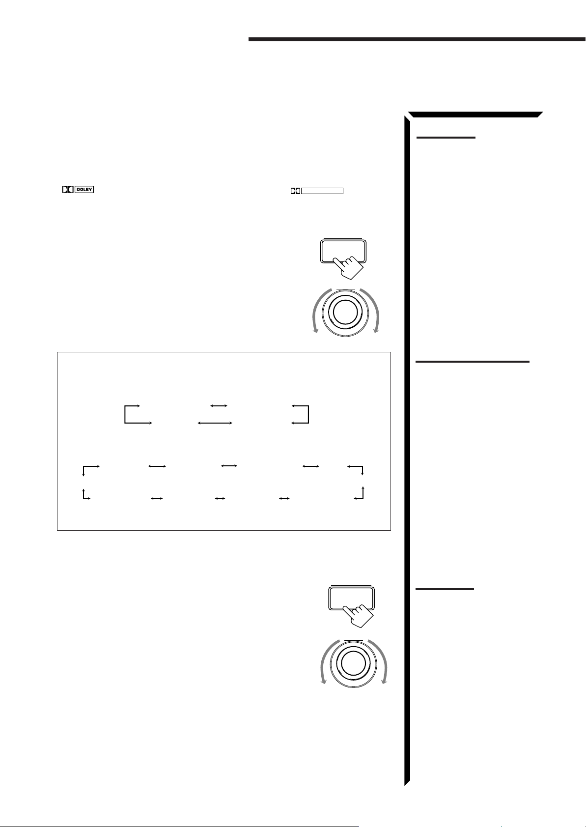
Using the DSP Modes
On the front panel:
You can also use the buttons on the front panel to adjust the Theater Surround mode.
However, no test tone is available when using the buttons on the front panel. So, make
adjustments while listening to the sound of the source played back.
1. Select and play the source encoded with Dolby Digital (bearing the mark
DIGITAL
) or with Dolby Surround (bearing the mark
• When you play back the source encoded with Dolby Digital and select the digital
input for that source, the Ÿ DIGITAL indicator lights up on the display.
2. Press DSP MODE.
The current DSP mode appears on the display.
3. Turn MULTI JOG until “THEATER” or “DIGTHEATER” appears on the display, while the indication of
the previous step is still on the display.
The DSP and THEATER indicators also light up on the display.
DOLBY SURROUND
DSP MODE
).
MULTI JOG
Notes:
• To enjoy the software encoded
with Dolby Digital, you must
connect the source
component using the digital
terminal on the rear of this
receiver.
• The Surround mode is not
used with the other DSP
modes such as the DAP mode
and 3D-PHONIC mode. When
the Surround mode is turned
on, the other DSP mode, if
used, will be turned off.
As you turn it, the DSP modes change as follows:
When the digital input is selected to play the source encoded with Dolby
Digital:
DIG-THEATER
DSP OFF
HEADPHONE
3D DIGITAL
For other sources:
LIVE CLUBTHEATER
DANCE CLUB
DSP OFF
3D THEATER
3D DRAMA
3D ACTION
HEADPHONE
If you need to make any adjustment, go to the following steps.
4. Adjust the speaker output levels as follows.
1) Press BALANCE/SURROUND ADJUST repeatedly
until one of the indications appears on the display.
“CENTER LEVEL”: To adjust the center speaker level.
“REAR L LEVEL”: To adjust the left speaker level.
“REAR R LEVEL”: To adjust the right speaker level.
2) Turn MULTI JOG to adjust the selected speaker output
level (from –10 dB to +10 dB), while the indication of the
previous step is still on the display.
3) Repeat 1) and 2) to adjust the other speaker output
levels.
HALL
PAVILION
BALANCE/SURROUND
ADJUST
MULTI JOG
Notes on the indications:
• The PRO LOGIC indicator
lights up when the Dolby Pro
Logic decoder built in this
receiver is activated.
• The Dolby Pro Logic decoder
is used not only for the analog
sources but also for the
sources encoded with Dolby
Digital in the following cases:
– When only front channel
signals are encoded.
– When front channel and
monaural rear channel
signals are encoded.
While the Dolby Pro Logic is
activated for this type of Dolby
Digital source, the Ÿ DIGITAL
indicator goes off.
Notes:
• You cannot adjust the center
speaker level when “CENTER
SPK” is set to “NONE” (see
page 19).
• You cannot adjust the rear
speaker levels when “REAR
SPK” is set to “NONE” (see
page 19).
39
Page 43

5. Press BALANCE/SURROUND ADJUST repeatedly
until “CENTER TONE” appears on the display.
The display changes to show the current setting.
BALANCE/SURROUND
ADJUST
6. Turn MULTI JOG to select the center tone level you want,
while the indication of the previous step is still on the
display.
The center tone adjustment affects the mid-frequency
range, which the human voice is mostly made up of.
As you turn it, the display changes to show the
following:
SHARP1 SHARP2FLATSOFT2 SOFT1
7. Press BALANCE/SURROUND ADJUST repeatedly
until “DSP EFFECT” appears on the display.
The display changes to show the current setting.
8. Turn MULTI JOG to select the effect level, while the
indication of the previous step is still on the display.
As you turn it, the effect level changes as follows:
DSP EFFECT 1 DSP EFFECT 2
DSP EFFECT 5
DSP EFFECT 4
DSP EFFECT 3
As the number increases, the surround effect becomes
stronger.
MULTI JOG
BALANCE/SURROUND
ADJUST
MULTI JOG
Note:
You cannot adjust the effect
level when “REAR SPK” is set
to “NONE” (see page 19).
To cancel the Theater Surround mode
Turn MULTI JOG until “DSP OFF” appears in step 3.
The DSP and THEATER indicators goes off.
40
Page 44

Using the On-Screen Menus
You can use the menus on the TV screen to control the receiver.
To use this function, you need to connect the TV to the MONITOR OUT jack on the rear panel (see page 9),
and set the TV’s input mode to the proper position to which the receiver is connected.
Selecting the Source to Play (Also see page 13)
1. Press any button of ON SCREEN CONTROL % / fi / @ / # once.
The MAIN MENU appears on the TV.
MAIN MENU
SOURCE :ch 1 FM 87.5
VISUAL :VCR1
MODE :OFF
SOUND CONTROL
**
TUNER CONTROL
**
SETTING
**
VOLUME : 20
:OPERATE
MHz
**
**
**
MAIN MENU
Shows the buttons you can use on the current
menu.
In this case, use % / fi to move
down, and @ / # to select, adjust or set the
item.
2. Press ON SCREEN CONTROL % / fi to move to “SOURCE.”
3. Press ON SCREEN CONTROL @ / # to select the source.
4. When you finish, press EXIT.
The menu disappears from the TV.
Selecting the Different Sources for Picture and Sound
Note
The on-screen display will
disappear if no operation is done
for about one minute.
up and
You can view the pictures played back on a video component while listening to any
source.
1. Press any button of ON SCREEN CONTROL % / fi / @ / # once.
The MAIN MENU appears on the TV.
2. Press ON SCREEN CONTROL % / fi to move to “VISUAL.”
3. Press ON SCREEN CONTROL @ / # to select a different video source.
• When you select “OSD,” see page 49.
4. When you finish, press EXIT.
The menu disappears from the TV.
Using the DSP Modes (Also see pages 29, 32, 34, 37)
1. Press any button of ON SCREEN CONTROL % / fi / @ / # once.
The MAIN MENU appears on the TV.
2. Press ON SCREEN CONTROL % / fi to move to “MODE.”
3. Press ON SCREEN CONTROL @ / # to select the DSP mode you want to use.
MAIN MENU
MAIN MENU
SOURCE :PHONO
VISUAL :VCR1
MODE :OFF
SOUND CONTROL
**
TUNER CONTROL
**
SETTING
**
VOLUME : 20
MAIN MENU
MAIN MENU
SOURCE :VCR1
VISUAL :VCR1
MODE :PRO LOGIC
SOUND CONTROL
**
TUNER CONTROL
**
SETTING
**
VOLUME : 20
:OPERATE
:OPERATE
**
**
**
**
**
**
4. When you finish, press EXIT.
The menu disappears from the TV.
41
Page 45

Adjusting the Front Speaker Output Balance (Also see page 18)
MAIN MENU
SOURCE :VCR1
VISUAL :VCR1
MODE :OFF
SOUND CONTROL
TUNER CONTROL
SETTING
VOLUME : 20
:ENTER
**
**
**
**
**
**
1. Press any button of ON SCREEN CONTROL % / fi / @ / # once.
The MAIN MENU appears on the TV.
2. Press ON SCREEN CONTROL % / fi to move to “SOUND CONTROL,”
then press @ / #.
The SOUND CONTROL menu appears on the TV.
3. Press ON SCREEN CONTROL % / fi to move to “BAL.” (Balance).
4. Press ON SCREEN CONTROL @ / # to adjust the balance.
5. When you finish, press EXIT repeatedly until the menu disappears from the
TV.
Listening at Low Volume (Loudness) (Also see page 18)
1. Press any button of ON SCREEN CONTROL % / fi / @ / # once.
The MAIN MENU appears on the TV.
2. Press ON SCREEN CONTROL % / fi to move to “SOUND CONTROL,”
then press @ / #.
The SOUND CONTROL menu appears on the TV.
3. Press ON SCREEN CONTROL % / fi to move to “LOUDNESS.”
4. Press ON SCREEN CONTROL @ / # to turn the loudness “ON” or “OFF.”
5. When you finish, press EXIT repeatedly until the menu disappears from the
TV.
MAIN MENU
SOUND CONTROL menu
SOUND CONTROL
SURROUND LEVEL
****
SEA
****
BAL.:R-21
LOUDNESS : OFF
INPUT ATT : NORMAL
SUBWFR LEVEL: 0
NEXT PAGE
dB
:OPERATE
SOUND CONTROL menu
SOUND CONTROL
SURROUND LEVEL
****
SEA
****
BAL.:R-21
LOUDNESS : OFF
INPUT ATT : NORMAL
SUBWFR LEVEL: 0
NEXT PAGE
dB
:OPERATE
Attenuating the Input Signal (Also see page 15)
This function is available only for the sources connected using the analog terminals, and
takes effect only when the DSP mode is in use.
1. Press any button of ON SCREEN CONTROL % / fi / @ / # once.
The MAIN MENU appears on the TV.
2. Press ON SCREEN CONTROL % / fi to move to “SOUND CONTROL,”
then press @ / #.
The SOUND CONTROL menu appears on the TV.
3. Press ON SCREEN CONTROL % / fi to move to “INPUT ATT.”
4. Press ON SCREEN CONTROL @ / # to turn the function on (“ATT ON”) or
off (“NORMAL”).
5. When you finish, press EXIT repeatedly until the menu disappears from the
TV.
SOUND CONTROL menu
SOUND CONTROL
SURROUND LEVEL
****
SEA
****
BAL.:R-21
LOUDNESS : OFF
INPUT ATT : NORMAL
SUBWFR LEVEL: 0
NEXT PAGE
dB
:OPERATE
42
Page 46
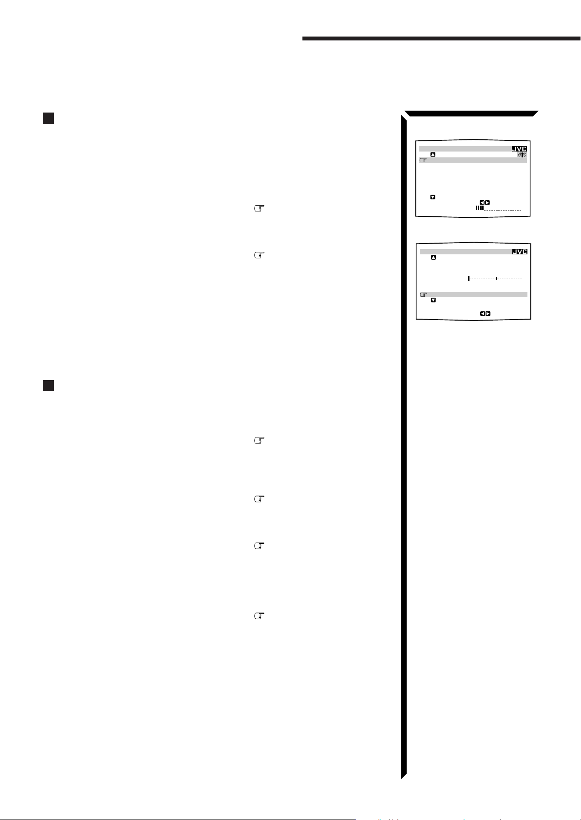
MAIN MENU
SOURCE :ch 1 FM 87.5
MHz
VISUAL :VCR1
MODE :OFF
SOUND CONTROL
TUNER CONTROL
SETTING
VOLUME : 20
:OPERATE
**
**
**
**
**
**
SOUND CONTROL
SURROUND LEVEL
SEA
BAL.:R-21
LOUDNESS : OFF
INPUT ATT : NORMAL
SUBWFR LEVEL: 0
dB
NEXT PAGE
:OPERATE
****
****
Using the On-Screen Menus
Adjusting the Subwoofer Output Level (Also see page 16)
You can adjust the subwoofer output level if you have selected “YES” for the
“SUBWOOFER” (see page 18).
1. Press any button of ON SCREEN CONTROL % / fi / @ / # once.
The MAIN MENU appears on the TV.
2. Press ON SCREEN CONTROL % / fi to move to “SOUND CONTROL,”
then press @ / #.
The SOUND CONTROL menu appears on the TV.
3. Press ON SCREEN CONTROL % / fi to move to “SUBWFR LEVEL”
(Subwoofer Level).
4. Press ON SCREEN CONTROL @ / # to adjust the subwoofer output level.
5. When you finish, press EXIT repeatedly until the menu disappears from the
TV.
MAIN MENU
SOUND CONTROL menu
Adjusting the DSP Modes (Also see pages 29, 32, 34, 37)
1. Press any button of ON SCREEN CONTROL % / fi / @ / # once.
The MAIN MENU appears on the TV.
2. Press ON SCREEN CONTROL % / fi to move to “MODE.”
3. Press ON SCREEN CONTROL @ / # to select the DSP mode you want to
adjust.
4. Press ON SCREEN CONTROL % / fi to move to “SOUND CONTROL,”
then press @ / #.
The SOUND CONTROL menu appears.
5. Press ON SCREEN CONTROL % / fi to move to “SURROUND LEVEL,”
then press @ / #.
The SURROUND LEVEL menu appears.
• If you select “HEADPHONE” in step 3, the SURROUND LEVEL menu will not
appear.
6. Press ON SCREEN CONTROL % / fi to move to the item you want to set
or adjust, then press ON SCREEN CONTROL @ / #.
On these adjustment menus, you can do the following:
For 3D-PHONIC modes:
“DSP EFFECT”: Adjust the effect level.
For DAP modes (LIVE CLUB, DANCE CLUB, HALL, PAVILION):
“REAR L LEVEL”: Adjust the left rear speaker output level. *
“REAR R LEVEL”: Adjust the right rear speaker output level. *
“DSP EFFECT”: Select the effect level.
43
Page 47

For Dolby Surround Pro Logic:
SURROUND LEVEL
:OPERATE
TEST TONE : OFF
CENTER LEVEL: 0
dB
REAR L LEVEL: 0
dB
REAR R LEVEL: 0dB
CENTER TONE : FLAT
DSP EFFECT : 3
MAIN MENU
SOURCE :VCR1
VISUAL :VCR1
MODE :OFF
SOUND CONTROL
TUNER CONTROL
SETTING
VOLUME : 20
:ENTER
**
**
**
**
**
**
“TEST TONE”: Output a test tone.
“CENTER LEVEL”: Adjust the center speaker output level. **
“REAR L LEVEL”: Adjust the left rear speaker output level. *
“REAR R LEVEL”: Adjust the right rear speaker output level. *
“CENTER TONE”: Select the center tone level. **
For Dolby Digital:
“TEST TONE”: Output a test tone.
“CENTER LEVEL”: Adjust the center speaker output level. **
“REAR L LEVEL”: Adjust the left rear speaker output level. *
“REAR R LEVEL”: Adjust the right rear speaker output level. *
“CENTER TONE”: Select the center tone level. **
For Theater Surround and Digital Theater Surround:
“TEST TONE”: Output a test tone.
“CENTER LEVEL”: Adjust the center speaker output level. **
“REAR L LEVEL”: Adjust the left rear speaker output level. *
“REAR R LEVEL”: Adjust the right rear speaker output level. *
“CENTER TONE”: Select the center tone level. **
“DSP EFFECT”: Select the effect level. *
7. When you finish, press EXIT repeatedly until the menu disappears from the
TV.
Example:
SURROUND LEVEL menu
for Theater Surround
Notes:
* Not displayed when “REAR
SPK” is set to “NONE” (see
page 19).
** Not displayed when
“CENTER SPK” is set to
“NONE” (see page 19).
Selecting Your Favorite SEA Mode (Also see page 26)
1. Press any button of ON SCREEN CONTROL % / fi / @ / # once.
The MAIN MENU appears on the TV.
2. Press ON SCREEN CONTROL % / fi to move to “SOUND CONTROL,”
then press @ / #.
The SOUND CONTROL menu appears.
3. Press ON SCREEN CONTROL % / fi to move to “SEA,” then press @ / #.
The SEA menu appears.
4. Press ON SCREEN CONTROL % / fi to move to “SEA MODE.”
5. Press ON SCREEN CONTROL @ / # to select the SEA mode you want.
6. When you finish, press EXIT repeatedly until the menu disappears from the
TV.
MAIN MENU
SOUND CONTROL menu
SOUND CONTROL
SURROUND LEVEL
****
SEA
****
BAL.:CNTR
LOUDNESS : OFF
INPUT ATT : NORMAL
SUBWFR LEVEL: 0
NEXT PAGE
dB
:ENTER
SEA menu
SEA
SEA MODE :ROCK
SEA ADJUST
**
100 10kHz1k
**
:OPERATE
44
Page 48

Using the On-Screen Menus
SETTING 1
SUBWOOFER : NO
FRONT SPK : LARGE
CENTER SPK : SMALL
REAR SPK : LARGE
CNTR DELAY : 3msec
REAR DELAY : 5msec
NEXT PAGE
:ENTER
****
SETTING 2
CROSSOVER :100Hz
LFE ATT. : 0
dB
COMP. : OFF
DIGITAL 1 : DBS
DIGITAL 2 : CD
DIGITAL 3 : MD
PREVIOUS PAGE
:ENTER
****
Creating Your Own SEA Mode (Also see page 27)
1. Press any button of ON SCREEN CONTROL % / fi / @ / # once.
The MAIN MENU appears on the TV.
2. Press ON SCREEN CONTROL % / fi to move to “SOUND CONTROL,”
then press @ / #.
The SOUND CONTROL menu appears.
3. Press ON SCREEN CONTROL % / fi to move to “SEA,” then press @ / #.
The SEA menu appears.
4. Press ON SCREEN CONTROL % / fi to move to “SEA ADJUST,” then
press @ / #.
The SEA ADJUST menu appears.
5. Press ON SCREEN CONTROL % / fi / @ / # to adjust the SEA mode as you
want.
@ / # : Select the frequency ranges.
% / fi : Adjust the frequency levels.
6. Press SET to store the setting into the SEA USERMODE.
• If you press EXIT, without pressing SET in this step, you can return to the SEA
menu. (The adjustment you have made is active but not stored.)
7. When you finish, press EXIT repeatedly until the menu disappears from the
TV.
MAIN MENU
MAIN MENU
SOURCE :VCR1
VISUAL :VCR1
MODE :OFF
SOUND CONTROL
**
TUNER CONTROL
**
SETTING
**
VOLUME : 20
:ENTER
**
**
**
SOUND CONTROL menu
SOUND CONTROL
SURROUND LEVEL
****
SEA
****
BAL.:CNTR
LOUDNESS : OFF
INPUT ATT : NORMAL
SUBWFR LEVEL: 0
NEXT PAGE
dB
:ENTER
SEA menu
SEA
SEA MODE :ROCK
SEA ADJUST
**
100 10kHz1k
**
:OPERATE
SEA ADJUST menu
SEA ADJUST
SEA USERMODE
Basic Settings
1. Press any button of ON SCREEN CONTROL % / fi / @ / # once.
The MAIN MENU appears on the TV.
2. Press ON SCREEN CONTROL % / fi to move to “SETTING,” then press
@ / #.
The SETTING 1 or SETTING 2 menu appears.
3. Press ON SCREEN CONTROL % / fi to the setting item you want to adjust.
• To go to the SETTING 2 menu, move to “NEXT PAGE,” then press @ / #.
• To go back to the SETTING 1 menu, move to “PREVIOUS PAGE,” then
press @ / #.
On the SETTING 1 and 2 menus, you can do the following:
“SUBWOOFER”: Set the subwoofer information (See page 18).
“FRONT SPK”: Set the front speaker information (See page 19).
“CENTER SPK”: Set the center speaker information (See page 19).
“REAR SPK”: Set the rear speaker information (See page 19).
“CNTR DELAY”: Adjust the delay time of the center speaker output (See page 20).
“REAR DELAY”: Adjust the delay time of the rear speaker output (See page 20).
“CROSSOVER”: Set the crossover frequency (See page 20).
“LFE ATT.”: Set the low frequency effect attenuator level (See page 21).
“COMP.”: Set the dynamic range compression (See page 21).
“DIGITAL 1/2/3”: Set the digital input terminal (See page 19).
45
100 10kHz1k
SETTING 1 menu
SETTING 2 menu
SET
:MEMORY
Page 49

4. Press ON SCREEN CONTROL @ / # to set (or adjust) the setting item selected
MAIN MENU
SOURCE :ch 1 FM 87.5
MHz
VISUAL :VCR1
MODE :OFF
SOUND CONTROL
TUNER CONTROL
SETTING
VOLUME : 20
:ENTER
**
**
**
**
**
**
PRESET MEMORY
FM 87.5
MHz
AUTO
PRESET CH : CH 1
PRESET NAME: WABC
:OPERATE
:MEMORY
SET
in step 3.
5. When you finish, press EXIT repeatedly until the menu disappears from the
TV.
Operating the Tuner
1. Press any button of ON SCREEN CONTROL % / fi / @ / # once.
The MAIN MENU appears on the TV.
2. Press ON SCREEN CONTROL % / fi to move to “TUNER CONTROL,”
then press @ / #.
The TUNER CONTROL menu appears.
3. Press ON SCREEN CONTROL % / fi to move to the item you want to set
or adjust, then press ON SCREEN CONTROL @ / #.
On the TUNER CONTROL menu, you can do the following:
“PRESET CH”: Select a preset channel station. (See page 24)
“BAND”: Select the band. (See page 23)
“FREQUENCY”: Tune in a station manually. (See page 23)
“FM MODE”: Select the FM reception mode. (See page 24) *
“PRESET MEMORY”: See “Storing the Preset Stations” below.
4. When you finish, press EXIT repeatedly until the menu disappears from the
TV.
MAIN MENU
TUNER CONTROL menu
TUNER CONTROL
PRESET CH : 1
BAND :FM
FREQUENCY : 87.5
FM MODE :AUTO
PRESET MEMORY
****
MHz
:OPERATE
Note:
* Not displayed when an AM
station is selected.
Storing the Preset Stations (Also see page 23)
1. Press any button of ON SCREEN CONTROL % / fi / @ / # once.
The MAIN MENU appears on the TV.
2. Press ON SCREEN CONTROL % / fi to move to “TUNER CONTROL,”
then press @ / #.
The TUNER CONTROL menu appears.
3. Tune into a station on the TUNER CONTROL menu, referring to “Operating
the T uner” above.
4. Press ON SCREEN CONTROL % / fi to move to “PRESET MEMORY,”
then press @ / #.
The PRESET MEMORY menu appears.
5. Press ON SCREEN CONTROL % / fi to move to “PRESET CH.”
6. Press ON SCREEN CONTROL @ / # to select a preset station number you
want.
7. Press SET to store the setting.
8. When you finish, press EXIT repeatedly until the menu disappears from the
TV.
PRESET MEMORY menu
46
Page 50

Using the On-Screen Menus
PRESET MEMORY
SET
:MEMORY
:OPERATE
FM 107.9
MHz
AUTO
PRESET CH : CH39
PRESET NAME: WABC
A B C D E F G H I J K
L M N O P Q R S T U V
W X Y Z
1 2 3 4 5 6 7 8 9 0
SPACE
CANCEL
TUNER CONTROL
PRESET CH :39
BAND :FM
FREQUENCY : 87.5
MHz
FM MODE :AUTO
PRESET MEMORY
:ENTER
****
PRESET MEMORY
FM 87.5
MHz
AUTO
PRESET CH : CH39
PRESET NAME: WABC
:OPERATE
:MEMORY
SET
Assigning Names to the Preset Stations (Also see page 25)
1. Press any button of ON SCREEN CONTROL % / fi / @ / # once.
The MAIN MENU appears on the TV.
2. Press ON SCREEN CONTROL % / fi to move to “TUNER CONTROL,”
then press @ / #.
The TUNER CONTROL menu appears.
3. Press ON SCREEN CONTROL % / fi to move to “PRESET CH.”
4. Press ON SCREEN CONTROL @ / # to select a preset station.
5. Press ON SCREEN CONTROL % / fi to move to “PRESET MEMORY,”
then press @ / #.
The PRESET MEMORY menu appears.
6. Press ON SCREEN CONTROL % / fi to move to “PRESET NAME,” then
press SET.
The character entry screen appears.
7. Press ON SCREEN CONTROL % / fi / @ / # to move in front of a
character you want.
You can also select the following:
SPACE: To enter space CANCEL: To erase the character
: To go back to the previous character position or go to the next character
position
MAIN MENU
MAIN MENU
SOURCE :ch 1 FM 87.5
VISUAL :VCR1
MODE :OFF
SOUND CONTROL
**
TUNER CONTROL
**
SETTING
**
VOLUME : 20
:ENTER
TUNER CONTROL menu
PRESET MEMORY menu
MHz
**
**
**
8. Press SET to enter the selected character.
9. Repeat steps 7 and 8 to enter up to four characters.
10.Press ON SCREEN CONTROL % / fi / @ / # to move to “PRESET
NAME,” then press SET to store the setting.
The TUNER CONTROL menu appears again.
11.When you finish, press EXIT repeatedly until the menu disappears from the
TV.
PRESET MEMORY menu:
Character entry screen
PRESET MEMORY
FM 107.9
PRESET CH : CH39
PRESET NAME:
A B C D E F G H I J K
L M N O P Q R S T U V
W X Y Z
1 2 3 4 5 6 7 8 9 0
SPACE
MHz
AUTO
CANCEL
SET
:MEMORY
:OPERATE
47
Page 51

COMPU LINK Remote Control System
The COMPU LINK remote control system allows you to operate JVC audio components through the remote
sensor on the receiver.
To use this remote control system, you need to connect JVC audio components through
the COMPU LINK-3 (SYNCHRO) jacks (see below) in addition to the connections
using cables with RCA pin plugs (see page 8) (and a digital cable if you want — see
page 11).
• Make sure that the AC power cords of these components are unplugged before
connection. Plug the AC power cords only after all connections are complete.
COMPU LINK – 3
(SYNCHRO)
CD player
Cassette deck
or
MD recorder
Turntable
This remote control system allows you to use four functions listed below.
Remote Control through the Remote Sensor on the Receiver
You can control the connected audio components through the remote sensor on the
receiver using this remote control. Aim the remote control directly at the remote sensor
on the receiver. For details, see pages 58 and 59.
Notes:
• If your audio component has
two COMPU LINK-3
(SYNCHRO) jacks, you can
use either one. If it has only
one COMPU LINK-3
(SYNCHRO) jack, connect it
so that it is the last item in the
series of components. (For
example, the turntable or CD
player in the diagram to the
left.)
• To operate the cassette deck
or MD recorder using the
COMPU LINK remote control
system, set the source name
correctly. (See page 17.)
• Refer also to the manuals
supplied with your audio
components.
Automatic Source Selection
When you press the play (
33
3) button on a connected component or on its own remote
33
control, the receiver automatically turns on and changes the source to the component.
On the other hand, if you select a new source on the receiver or the remote control, the
selected component begins playing immediately.
In both cases, the previously selected source continues playing without sound for a few
seconds.
Automatic Power On/Off (Standby): only possible with the COMPU
LINK-3 connection
Both the CD player and cassette deck (or MD recorder) turn on and off (standby) along
with the receiver.
When you turn on the receiver, the CD player or cassette deck (or MD recorder) will
turn on automatically, depending on which component has been previously selected.
When you turn off the receiver, both the CD player and cassette deck (or MD recorder)
will turn off (standby).
Synchronized Recording
Synchronized recording means the cassette deck (or MD recorder) starts recording as
soon as a CD or a record begins playing.
To use synchronized recording, follow these steps:
1. Put a tape in the cassette deck (or an MD in the MD recorder), and a disc in the
CD player (or a record on the turntable).
2. Press the record (
¶¶
¶) button and the pause (
¶¶
88
8) button on the cassette deck (or
88
MD recorder) at the same time.
This puts the cassette deck (or MD recorder) into recording pause.
If you do not press the record (¶) button and pause (8) button at the same time, the
synchronized recording feature will not operate.
3. Press the play (
33
3) button on the CD player or on the turntable.
33
The source changes on the receiver, and as soon as play starts, the cassette deck (or
MD recorder) starts recording. When the play ends, the cassette deck (or MD
recorder) enters recording pause, and stops about 4 seconds later.
Notes:
• During synchronized
recording, the selected source
cannot be changed.
• If your CD player is playing in
program mode, a 4-second
blank is recorded between
tracks so that the music scan
feature of your cassette deck
can be used on the recorded
tape.
• If the power of any component
is shut off during synchronized
recording, the COMPU LINK
remote control system may
not operate properly. In this
case, you must start again
from the beginning.
48
Page 52

TEXT COMPU LINK Remote Control System
The TEXT COMPU LINK remote control system has been newly developed to deal with the disc information
recorded in the CD Text* and MDs. Using these information in the discs, you can operate the CD player or
MD recorder equipped with the TEXT COMPU LINK remote control system through the receiver.
CONNECTIONS:
To use this remote control system, you need to connect the CD player and/or MD
recorder you want to operate, following the procedures below.
1. If you have already plugged your CD player, MD recorder, and this receiver
into the AC outlets, unplug their AC power cords first.
2. Connect your CD player, MD recorder, and this receiver as follows, through the
COMPU LINK-3 (SYNCHRO) jacks and TEXT COMPU LINK jacks.
1) COMPU LINK-3 (SYNCHRO) jacks: Use the cables with the monaural mini-
plugs (not supplied with this receiver)
COMPU LINK – 3
(SYNCHRO)
CD player
2) TEXT COMPU LINK jacks: Use the cables with the stereo mini-plugs (not
supplied with this receiver)
CD player
IMPORTANT:
Set the Master/Slave Selector on the rear to “1(MASTER UNIT).”
• “2(SLAVE UNIT)” is just for the serviceman’s use. The TEXT
COMPU LINK remote control system does not function with
the selector set to “2(SLAVE UNIT).”
MD recorder
MD recorder
TEXT
COMPU LINK
1(MASTER UNIT)
2(SLAVE UNIT)
* What is a CD Text?
In a CD Text, some information
about the disc (its disc title,
performer, composer, arranger,
etc.) is recorded.
Notes:
• If your audio component has
two COMPU LINK-3
(SYNCHRO) jacks, you can
use either one. If it has only
one COMPU LINK-3
(SYNCHRO) jack, connect it
so that it is the last item in the
series of components. (For
example, the CD player in the
diagram to the left.)
• If your audio component has
two TEXT COMPU LINK
jacks, you can use either one.
If it has only one TEXT
COMPU LINK jack, connect it
so that it is the last item in the
series of components. (For
example, the CD player in the
diagram to the left.)
• Refer also to the manuals
supplied with your CD player
or MD recorder.
3. Connect your CD player, MD recorder and this receiver, using the cables with
RCA pin plugs (see page 8) (and a digital cable if you want — see page 11).
4. Plug the AC power cords of these components above into the AC outlets.
5. When turning on these components for the first time, turn on the connected
components first, then turn on this receiver.
FUNCTIONS:
This remote control system allows you to use the functions listed below.
Displaying the Disc Information on the TV screen
Disc information such as its performer and disc title (and track titles only when a CD
Text is selected) is shown on the TV screen.
Disc Search: Only for CD Player
This remote control system can allow you to search discs by the performer, disc title,
and music genre.
With this disc search, you can easily find the disc you want to play.
Additional Functions:
• If your CD player has the User File function, you can select a disc from the groups.
* A “user file” is a group of the discs you make as you like on the CD player.
• If your CD player has the disc memory function, you can input the performer, disc
title, and music genre about these normal audio CDs on the TV screen.
Note:
If you turn on the receiver before
turning on the other components
after connecting components,
the TEXT COMPU LINK remote
control system does not work
correctly.
If this happens:
1. Turn off the all
components including
this receiver.
2. Turn on the connected
components.
3. Turn on this receiver.
49
Page 53

OPERATIONS
To use this remote control system, you need to connect the TV to the MONITOR OUT
jack on the rear panel (see page 9), and set the TV’s input mode to the proper position to
which the receiver is connected. Make sure you have connected the CD player
or MD recorder equipped with the TEXT COMPU LINK remote control
system. If not, you cannot use the following functions.
Showing the Disc Information on the TV Screen
1. Press any button of ON SCREEN CONTROL % / fi / @ / # once.
The MAIN MENU appears on the TV.
2. Press ON SCREEN CONTROL % / fi to move to “SOURCE.”
3. Press ON SCREEN CONTROL @ / # to select “CD” or “MD.”
4. Press ON SCREEN CONTROL % / fi to move to “VISUAL.”
5. Press ON SCREEN CONTROL @ / # to select “OSD,” then press EXIT.
The Disc Information screen appears on the TV.
Notes:
• The on-screen display will not
appear about one minute after
the power is turned on.
• The on-screen display will
disappear in the following
case:
– if no operation is done for
about 10 minutes.
– if you do any operation
other than explained in this
section.
• To control the MD recorder
using the TEXT COMPU LINK
remote control system, you
have to change the source
name shown on the display
from “TAPE” to “MD.” (See
page 17.)
• The number of characters to
show the disc information
such as the disc title or track
title is limited to 32. So if the
disc title, for example, is
longer than 32 characters,
only the first 32 characters are
shown.
• Some special characters such
as accented letters cannot be
displayed correctly.
1 Source name: CD or MD
2 Select
3 Track numbers and track titles.
• The current playing (selected) track is indicated in yellow.
• When you move
4 Select this (move
(see page 51).
5 Select this (move in front), then press SET to go to the USER FILE screen (see
page 53).
6 Select this (move
page 54).
7 Disc information such as the disc title, performer, and music genre.
When this is selected (
@ / #. Each time you press the button, the disc information (see the note) changes.
8 Select or , then press SET to change the track.
9 Usable buttons and their functions for the current selection.
Indication here will be changed according to what is currently selected ( in front)
on the screen.
or , then press SET to change the disc.
to a track number, you can change the track information by
pressing @ / #. Each time you press the button, the track information alternates
between its track title and its performer. (You can also start playing the track by
pressing SET.)
in front), then press SET to go to the DISC SEARCH screen
in front), then press SET to go to the TITLE INPUT screen (see
in front) , you can change the disc information by pressing
6. When you finish, press EXIT repeatedly until the MAIN MENU appears on
the TV.
To exit from the MAIN MENU:
1) Press ON SCREEN CONTROL % / fi to move to “VISUAL.”
2) Press ON SCREEN CONTROL @ / # to select any one other than “OSD,” then
press EXIT.
Note on
The following information will
appear on the display:
• Disc title
• Performer
• Genre
• Song writer
• Composer
• Arranger
• Message
Only recorded information will
be shown. If there is no data,
“NO DATA” will appear.
Note on
For example, the SET button will
be used to start play (PLAY), to
go to the next screen (ENTER),
and to determine the selection
(ENTER).
7
9
50
Page 54

TEXT COMPU LINK Remote Control System
Searching a Disc (Only for the CD player)
Search a disc by its performer:
1. Display the disc information screen by following the procedure on page 50.
2. Press ON SCREEN CONTROL % / fi to move to “SEARCH,” then
press SET.
The DISC SEARCH screen appears on the TV.
3. Press ON SCREEN CONTROL % / fi to move to “PERFORMER”, then
press SET.
The PERFORMER SEARCH screen appears.
4. Press ON SCREEN CONTROL % / fi / @ / # to move in front of the
first character of the performer you want to search, then press SET.
To correct the incorrect entry, press ON SCREEN CONTROL % / fi to
move in front of the correct character, then press SET.
To erase the incorrect entry, press ON SCREEN CONTROL % / fi to mov e to
“CANCEL,” then press SET.
5. Press SET again.
Disc search starts, then the SEARCH RESULT screen, showing the performers,
appears.
6. On the SEARCH RESULT screen, you can do the following:
DISC SEARCH screen
PERFORMER SEARCH
screen
SEARCH RESULT screen
• Changing the indication of the disc information: Press ON SCREEN CONTROL
% / fi to move to a searched disc, then press @ / #. Each time you press @ / #,
the disc information alternates between its performer and its disc title.
• Going to the Disc Information screen (see page 50): Press ON SCREEN
CONTROL % / fi to move to a searched disc, then press SET.
• Showing unseen disc information (if more than 5 discs are listed as a result of
the search): Press ON SCREEN CONTROL % / fi to move to (or ),
then press SET.
• Going back to the PERFORMER SEARCH screen: Press EXIT.
Search a disc by its disc title:
1. Display the disc information screen by following the procedure on page 50.
2. Press ON SCREEN CONTROL % / fi to move to “SEARCH,” then
press SET.
The DISC SEARCH screen appears on the TV.
3. Press ON SCREEN CONTROL % / fi to move “DISC TITLE”, then
press SET.
The DISC TITLE SEARCH screen appears.
4. Press ON SCREEN CONTROL % / fi / @ / # to move in front of the
first character of the disc title you want to search, then press SET.
Note
Symbols such as @, # or $
cannot be available for search.
DISC SEARCH screen
DISC TITLE SEARCH screen
To correct the incorrect entry, press ON SCREEN CONTROL % / fi to
move in front of the correct character, then press SET.
To erase the incorrect entry, press ON SCREEN CONTROL % / fi to mov e to
“CANCEL,” then press SET.
51
Page 55

5. Press SET again.
Disc search starts, then the SEARCH RESULT screen, showing the disc titles,
appears.
6. On the SEARCH RESULT screen, you can do the following:
• Changing the indication of the disc information: Press ON SCREEN CONTROL
% / fi to move to a searched disc, then press @ / #. Each time you press @ / #,
the disc information alternates between its disc title and its performer.
• Going to the Disc Information screen (see page 50): Press ON SCREEN
CONTROL % / fi to move to a searched disc, then press SET.
• Showing unseen disc information (if more than 5 discs are listed as a result of
the search): Press ON SCREEN CONTROL % / fi to move to (or ),
then press SET.
• Going back to the DISC TITLE SEARCH screen: Press EXIT.
SEARCH RESULT screen
Note
Symbols such as @, # or $
cannot be available for search.
Search a disc by its genre:
1. Display the disc information screen by following the procedure on page 50.
2. Press ON SCREEN CONTROL % / fi to move to “SEARCH,” then
press SET.
The DISC SEARCH screen appears on the TV.
3. Press ON SCREEN CONTROL % / fi to move to “GENRE”, then press
SET.
The GENRE SEARCH screen appears.
4. Press ON SCREEN CONTROL % / fi to move to the genre you want to
search, then press SET.
To show the unseen genres, press ON SCREEN CONTROL % / fi until they
appear.
Disc search starts, then the SEARCH RESULT screen, showing the disc titles,
appears.
5. On the SEARCH RESULT screen, you can do the following:
• Changing the indication of the disc information: Press ON SCREEN CONTROL
% / fi to move to a searched disc, then press @ / #. Each time you press @ / #,
the disc information alternates between its disc title and its performer.
• Going to the Disc Information screen (see page 50): Press ON SCREEN
CONTROL % / fi to move to a searched disc, then press SET.
• Showing unseen disc information (if more than 5 discs are listed as a result of
the search): Press ON SCREEN CONTROL % / fi to move to (or ),
then press SET.
• Going back to the GENRE SEARCH screen: Press EXIT.
GENRE SEARCH screen
SEARCH RESULT screen
52
Page 56

TEXT COMPU LINK Remote Control System
Using the User File (Only for the CD Player with the User
File Function)
You can use the User File function through this receiver.
For the User File function, refer to the manual supplied with your CD player.
Using your own User Files:
1. Display the disc information screen by following the procedure on page 50.
2. Press ON SCREEN CONTROL % / fi to move to “USER FILE,” then
press SET.
The USER FILE screen appears on the TV.
To show the unseen user files, press ON SCREEN CONTROL % / fi until they
appear.
3. Press ON SCREEN CONTROL % / fi to move to the User File you want,
then press SET.
The selected User File screen appears on the TV.
The disc information shown will be the disc title. (If no disc title information is
recorded for the discs, only the disc numbers will be shown.)
4. On this selected User File screen, you can do the following:
• Changing the indication of the disc information: Press ON SCREEN
CONTROL % / fi to move to a disc, then press @ / #. Each time you press @
/ #, the disc information alternates between its disc title and its performer.
• Starting a disc play: Press ON SCREEN CONTROL % / fi to move to a disc,
then press SET.
• Showing unseen disc information (if more than 5 discs are listed): Press ON
SCREEN CONTROL % / fi to move to (or ) and press SET.
• Going back to the USER FILE screen: Press EXIT.
USER FILE screen
User File 1 screen
53
Page 57

Entering the Disc Information
For the CD Player with the disc memory function:
You can use the disc memory function through this receiver.
The disc information (its performer, disc title, and its music genre) of normal audio CDs
will be stored into the memory built in the CD player.
For the disc memory function, refer to the manual supplied with your CD player.
• The performer, disc title, and music genre information are usually recorded in a CD
Text. However, if a CD Text has no genre information recorded in the disc itself, you
can input its music genre by yourself.
Note: You can enter the TITLE INPUT screens for a CD Text and input its titles.
Howev er, you cannot store the titles you have input for a CD Text.
Example: Entering the following information for Disc 1
Performer: “MICHEAL”
Disc title: “MY FAVORITE”
1. Display the disc information screen by following the procedure on page 50.
2. Press ON SCREEN CONTROL % / fi to move to “TITLE INPUT,” then
press SET.
The TITLE INPUT: PERFORMER screen appears on the TV.
3. Press ON SCREEN CONTROL % / fi / @ / # to move in front of a
character you want, then press SET to enter the character.
• If the current CD is a CD Text, go to step 5 without entering the performer.
TITLE INPUT: PERFORMER
screen
To use the lower case letters, press ON SCREEN CONTROL % / fi / @ / # to
move to
SHIFT
, then press SET.
To use the upper case letters again, press ON SCREEN CONTROL % / fi / @ / #
to move to
SHIFT
, then press SET.
4. Repeat step 3 until you finish putting a name (up to 32 characters) to this
User File.
To insert a space, press ON SCREEN CONTROL % / fi / @ / # to move to
SPACE
, then press SET.
To correct an incorrect character:
1) Press ON SCREEN CONTROL % / fi / @ / # to move to or , then
press SET until the incorrect character is selected.
2) Press ON SCREEN CONTROL % / fi / @ / # to move to CANCEL, then
press SET to erase the character.
3) Press ON SCREEN CONTROL % / fi / @ / # to move in front of an correct
character, then press SET to enter a correct character.
5. Press ON SCREEN CONTROL % / fi / @ / # to move to “DISC1:
MICHEAL (in this example),” then press SET.
The TITLE INPUT: DISC TITLE screen appears.
6. Enter the disc title, referring to steps 3 and 4.
• If the current CD is a CD Text, go to the next step without entering the disc
title.
TITLE INPUT: DISC TITLE
screen
Continued to the next page.
54
Page 58

TEXT COMPU LINK Remote Control System
7. Press ON SCREEN CONTROL % / fi / @ / # to move to “DISC1: MY
FAVORITE (in this example),” then press SET.
The TITLE INPUT: DISC 1 GENRE screen appears.
8. Press ON SCREEN CONTROL % / fi to move to the genre you want,
then press SET.
The Disc Information screen appears again.
To show the unseen genres, press ON SCREEN CONTROL % / fi until they
appear.
TITLE INPUT: DISC 1 GENRE
screen
For the MD recorder:
You can write the disc information (disc title and song titles) into the disc. You can only
write the song title for the song currently selected.
• If you have the CD-MD combination deck, you can also enter the disc information
(its performer, disc title, and its music genre) of normal audio CDs into the memory
built in the CD-MD combination deck. (To do this, follow the procedure on page
54.)
1. Display the disc information screen by following the procedure on page 50.
2. Press ON SCREEN CONTROL % / fi to move to “TITLE INPUT,” then
press SET.
The DISC TITLE INPUT screen appears on the TV.
3. Enter the disc title, referring to steps 3 and 4 on page 54.
• You can enter up to 32 character for the disc title.
4. Press ON SCREEN CONTROL % / fi / @ / # to move to the disc title
you have just entered, then press SET.
The disc title is stored into the memory, and the SONG TITLE INPUT screen for the
currently selected song appears.
• You can enter a song title for the song currently selected (indicated in yellow on
the TV screen).
Disc Information screen
DISC TITLE INPUT screen
5. Enter the song title, referring to steps 3 and 4 on page 54.
• You can enter up to 32 character for the song title.
6. Press ON SCREEN CONTROL % / fi / @ / # to move to the song title
you have just entered, then press SET.
The song title is stored into the memory, and the Disc Information screen appears
again.
55
Page 59

AV COMPU LINK Remote Control System
VIDEO
VIDEO S-VIDEO
MONITOR
OUT
VCR 1
IN
(PLAY)
OUT
(REC)
DVD
DVD
VHS
VCR
TV
To Video input 2
DVD player
DO NOT use these video terminals.
The AV COMPU LINK remote control system allows you to operate JVC video components (TV, VCR, and
DVD player) through the receiver.
CONNECTIONS:
To use this remote control system, you need to connect the video components you
want to operate, following the procedures below.
1. If you have already plugged your VCR1 (the VCR connected to the VCR 1
jacks), DVD player, TV, and this receiver into the AC outlets, unplug their AC
power cords first.
2. Connect your VCR1, DVD player, TV, and this receiver as follows, using the
cables with the monaural mini-plugs (not supplied).
VCR
VHS
AV
COMPU LINK
DVD player
DVD
AV
COMPU LINK
AV
COMPU LINK
IMPORTANT:
Connect to the terminal indicated in the
illustration.
DO NOT connect to the TV terminal.
If the AV COMPU LINK terminal
on the TV is “RECEIVER/AMP”
If the AV COMPU LINK terminal
on the TV is “AV COMPU LINK
EX”
TV
EX
RECEIVER/AMP
(VCR)
AV
COMPU LINK
EX
3. Connect the audio input/output jacks on VCR1, DVD player, TV, and this
receiver using the cables with RCA pin plug (see pages 9 to 10) (and a digital
cable if you want — see page 11).
AV
COMPU LINK
RECEIVER/
AMP
CAUTION:
The A V COMPU LINK remote
control system cannot control
the DBS tuner connected to the
TV/DBS jacks, and video
components connected to the
VIDEO and VCR2 jacks on the
receiver.
Note:
When connecting either the VCR
or DVD player to this receiver,
connect it directly to the receiver
using cable with the monaural
mini-plugs.
4. Connect the video input/output jacks on VCR1, DVD player, TV, and this
receiver as follows, using the cables with RCA pin plug or with S-video plug.
CASE1: If the components are equipped with the S-video
terminals
OUT
(REC)
VCR 1
IN
(PLAY)
terminal.
MONITOR
OUT
(PLAY)
MONITOR
To Video input 1
CASE3: If only the VCR is equipped with the S-video
TV
To Video input 1
To Video input 2
5. Plug the AC power cords of the components into the AC outlets.
6. When turning on the TV for the first time after the AV COMPU LINK
connection, turn the TV volume to the minimum using the TV volume control
on the TV.
VIDEO S-VIDEO
DVD
DVD
OUT
(REC)
VCR 1
IN
OUT
DO NOT use these video terminals.
VIDEO
DVD player
DO NOT use these video terminals.
VIDEO
VIDEO S-VIDEO
DVD
VCR
S-VHS
DVD player
DVD
VCR
S-VHS
CASE2: If the components are not equipped with the S-
video terminals
CASE4: If only the DVD player is equipped with the S-video
terminal.
DO NOT use these video terminals.
VIDEO
(PLAY)
MONITOR
DVD
OUT
(REC)
VCR 1
IN
OUT
VIDEO S-VIDEO
DVD player
DVD
VCR
VHS
To Video input 2
To Video input 1
TV
56
Page 60

FUNCTIONS:
This remote control system allows you to use five functions listed below.
Remote Control of DVD Player, VCR, and TV Using This Remote
Control
For the DVD player and the VCR:
• Aim the remote control directly at the remote sensor on the each component.
For the TV having AV COMPU LINK terminal “RECEIVER/AMP”:
• Aim the remote control directly at the remote sensor on the receiver when
operating the TV.
For the TV having AV COMPU LINK terminal “AV COMPU LINK EX”:
• Aim the remote control directly at the remote sensor on the TV when operating the
TV.
One-Touch Video Play
Simply by inserting a video cassette without its safety tab into the VCR1 (the VCR
connected to the VCR1 jacks), you can enjoy the video playback without setting other
switches manually.
The receiver automatically turns on and changes the source to “VCR1.”
The TV automatically turns on and changes the input mode to the position so that you
can view the playback picture.
When you insert a video cassette with its safety tab, press the play (
33
3) button on the
33
VCR1 or on the remote control. So, you can get the same result.
One-Touch DVD Play
Simply by starting playback on the DVD player, you can enjoy the DVD playback
without setting other switches manually.
The receiver automatically turns on and changes the source to “DVD”— “DVD” is
automatically selected.
The TV automatically turns on and changes the input mode to the position so that you
can view the playback picture.
Note:
Refer also to the manuals
supplied with your video
components.
Automatic Selection of TV’s Input Mode
• When you select “TV SOUND” as the source to play on the receiver, the TV
automatically changes the input mode to the TV tuner so that you can watch TV.
• When you select “VCR2,” as the source to play on the receiver, the TV
automatically changes the input mode to the Video Input 2 so that you can watch the
playback picture.
• When you select “DVD,” “VCR1,” “VIDEO” or “DBS” as the source to play on the
receiver, the TV automatically changes the input mode to the appropriate position
(either Video Input 1 or Video Input 2) so that you can view the playback picture.
Automatic Power On/Off (Standby)
The TV, VCR1 (the VCR connected to the VCR1 jacks), and DVD player turn on and
off along with the receiver.
• When you turn on the receiver;
• If the previously selected source is “VCR1,” the TV and VCR1 will turn on
automatically.
• If the previously selected source is “VIDEO” or “TV SOUND,” only the TV
will turn on automatically.
• If the previously selected source is “DVD,” the TV and DVD player will turn on
automatically.
When you turn off the receiver, the TV, VCR1 and the DVD player will turn off.
Note:
When you select “TV SOUND”
as the source on the receiver,
you cannot see the menu on the
TV screen since the AV COMPU
LINK remote control system
automatically changes the TV’s
input mode to the TV tuner.
If you do not mind stopping
listening to the TV sounds, you
can then show the on-screen
displays after changing the TV’s
input mode to the appropriate
position (either Video Input 1 or
Video Input 2) the receiver is
connected to.
Note:
If you turn off the receiver while
recording on the VCR1, the
VCR1 will not turn off, but
continue recording.
57
Page 61

Operating JVC’s Audio/Video Components
You can operate JVC’s audio and video components with this receiver’s remote control, since control
signals for JVC components are preset in the remote control.
IMPORTANT:
To operate JVC’s audio components using this remote control:
• You need to connect JVC audio components through the COMPU LINK-3
(SYNCHRO) jacks (see page 48) in addition to the connections using cables
with RCA pin plugs (see page 8) or using digital cables (see page 11).
• Aim the remote control directly at the remote sensor on the receiver.
Tuner
After pressing FM or AM (with the remote control mode
selector set to “AUDIO/TV/VCR”), you can perform the
following operations:
FM: Selects an FM broadcast.
AM: Selects an AM broadcast.
1 — 10, +10: Selects a preset channel number directly.
For channel number 5, press 5. For
channel number 15, press +10, then 5.
For channel number 20, press +10, then
10.
TUNING UP/TUNING DOWN:
Tunes into stations.
FM MODE/MUTE: Changes the FM reception mode.
Sound control section (Amplifier)
You can always perform the following operations (with the
remote control mode selector set to “AUDIO/TV/VCR”):
SURROUND MODE: Changes the DSP modes.
TV/CATV/
VCR 1
DBS
POWER POWER
POWER
DVD
VCR 1
CD TAPE/MD PHONO TV/DBS
AM
CNTR TONE CNTR
SURROUND
MODE
DIGITAL/
TEST REAR · L
ANALOG
INPUT
EFFECT
SOUND
SEA MODE
DISC
RETURN FM MODE/
CHANNEL
–
MUTE
–
ON SCREEN CONTROL
SET EXIT
VCR1
/REW PLAY
DOWN TUNING UP
TV/VIDEO
After pressing SOUND (with the remote control mode selector
set to “AUDIO/TV/VCR”), you can perform the following
RM-SR1024U REMOTE CONTROL
operations:
SEA MODE: Changes the SEA modes.
SUBWOOFER +/–: Adjusts the subwoofer output level.
CNTR +/–: Adjusts the center speaker output
level.
REAR•L +/–: Adjusts the left rear speaker output
level.
REAR•R +/–: Adjusts the right rear speaker output level.
EFFECT: Selects the effect level.
TEST: Turns on or off the test tone output.
CNTR TONE: Selects the center tone.
AUDIO
VCR 2 VIDEO
FM
1
456
7
/P
10
CONTROL
REC
–+
2 3
–+
–+
REAR · R
8
SUBWOOFER
–+
0
MUTE
+
VOLUME
MENU
STOP
LIGHT
ENTER
SLEEP
AUDIO/
TV/VCR
CATV
DBS
TAPE
FF/
PAUSE
MENU
9
+10
100+
+
Notes:
• If you use the buttons on the
front panel or the menu
function to choose a source,
the remote control will not
operate that source. To
operate a source with the
remote control, the source
must be selected using
buttons on the remote control.
• Check to see if its remote
control mode selector is set to
the correct position. To
operate audio system, TVs,
and VCRs, set it to “AUDIO/
TV/VCR.”
• Refer also to the manuals
supplied with your
components.
Note:
After adjusting sounds, press
the corresponding source
selecting button or DISC to
operate your target source by
using 10 keys; otherwise, 10
keys cannot be used for
operating your target source.
CD player
After pressing CD (with the remote control mode selector set to “AUDIO/TV/VCR”),
you can perform the following operations on a CD player:
PLAY: Starts playing.
44
4: Returns to the beginning of the current (or previous) track.
44
¢¢
¢: Skips to the beginning of the next track.
¢¢
STOP: Stops playing.
PAUSE: Pauses playing. To release it, press PLAY.
1 — 10, +10: Selects a track number directly.
For track number 5, press 5. For track number 15, press +10, then 5. For
track number 20, press +10, then 10. For track number 30, press +10,
+10, then 10.
58
Page 62

Operating JVC’s Audio/Video Components
CD player-changer
After pressing DISC (with the remote control mode selector set
to “AUDIO/TV/VCR”), you can perform the following
operations on the CD player-changer:
PLAY: Starts playing.
44
4: Returns to the beginning of the current (or
44
previous) track.
¢¢
¢: Skips to the beginning of the next track.
¢¢
STOP: Stops playing.
PAUSE: Pauses playing. To release it, press the PLAY
button.
1 — 6, 7/P: Select the number of a disc installed in a CD
player-changer.
After pressing CD (with the remote control mode selector set to
“AUDIO/TV/VCR”), you can perform the following operations
on the CD player-changer:
1 — 10, +10: Selects a track number directly.
For track number 5, press 5. For track number
TV/CATV/
VCR 1
DBS
POWER POWER
POWER
DVD
CD TAPE/MD PHONO TV/DBS
AM
SURROUND
MODE
DIGITAL/
ANALOG
INPUT
SOUND
DISC
–
MUTE
SET EXIT
VCR1
TV/VIDEO
VCR 2 VIDEO
VCR 1
FM
CNTR TONE CNTR
–+
1
2 3
TEST REAR · L
–+
456
EFFECT
–+
REAR · R
8
7
/P
SUBWOOFER
–+
SEA MODE
10
0
RETURN FM MODE/
MUTE
CHANNEL
+
VOLUME
–
ON SCREEN CONTROL
MENU
CONTROL
/REW PLAY
DOWN TUNING UP
REC
STOP
LIGHT
ENTER
AUDIO
SLEEP
TAPE
FF/
PAUSE
MENU
9
+10
100+
AUDIO/
TV/VCR
CATV
DBS
+
15, press +10, then 5. For track number 20,
press +10, then 10. For track number 30, press
RM-SR1024U REMOTE CONTROL
+10, +10, then 10.
Turntable
After pressing PHONO (with the remote control mode selector
set to “AUDIO/TV/VCR”), you can perform the following
operations on the turntable:
PLAY: Starts playing.
STOP: Stops playing.
Cassette deck
After pressing TAPE/MD or TAPE CONTROL (with the
remote control mode selector set to “AUDIO/TV/VCR”), you
can perform the following operations on the cassette deck:
PLAY: Starts playing.
REW: Fast winds the tape from right to left.
FF: Fast winds the tape from left to right.
STOP: Stops operations.
PAUSE: Pauses playing or recording temporarily. To release it, press the PLAY button.
¶¶
REC
¶: Press this button with the PLAY button to start recording.
¶¶
Press this button with the PAUSE button to enter recording pause.
Notes:
• To operate the cassette deck
or MD recorder using the
COMPU LINK remote control
system, set the source name
correctly. (See page 17.)
• You can use either the TAPE/
MD button or the TAPE
CONTROL button to activate
the buttons listed to the left. If
you press TAPE/MD, the
playing source also changes.
On the other hand, if you
press TAPE CONTROL, the
playing source does not
change.
MD recorder
After pressing TAPE/MD or TAPE CONTROL (with the remote control mode selector
set to “AUDIO/TV/VCR”), you can perform the following operations on the MD
recorder:
PLAY: Starts playing.
44
4: Returns to the beginning of the current (or previous) track.
44
¢¢
¢: Skips to the beginning of the next track.
¢¢
STOP: Stops playing.
PAUSE: Pauses playing. To release it, press the PLAY button.
¶¶
REC
¶: Press this button with the PLAY button to start recording.
¶¶
Press this button with the PAUSE button to enter recording pause.
59
Page 63

IMPORTANT:
To operate JVC’s video components using this remote control:
• You need to connect JVC video components through the AV COMPU LINK
jacks (see page 56) in addition to the connections using cables with RCA pin
plugs (see pages 9 to 10) or using a digital cable (see page 11).
• When using the remote control:
– For the DVD player and the VCR: Aim the remote control directly at the
remote sensor on the each component.
– For the TV having AV COMPU LINK terminal “RECEIVER/AMP”: Aim the
remote control directly at the remote sensor on the receiv er when operating the
TV.
– For the TV having AV COMPU LINK terminal “AV COMPU LINK EX”: Aim
the remote control directly at the remote sensor on the TV when operating the
TV.
VCR1 (the VCR connected to the VCR1 jacks)
You can always perform the following operations (with the
remote control mode selector set to “AUDIO/TV/VCR”):
VCR1 POWER: Turns on or off the VCR1.
After pressing VCR1 or VCR1 CONTROL (with the remote
control mode selector set to “AUDIO/TV/VCR”), you can
perform the following operations on the VCR:
PLAY: Starts playing.
REW: Rewinds a tape.
FF: Fast winds a tape.
STOP: Stops operations.
PAUSE: Pauses playing or recording temporarily. To
release it, press the PLAY button.
¶¶
REC
¶: Press this button with the PLAY button to
¶¶
start recording.
Press this button with the PAUSE button to
enter recording pause.
CHANNEL +/–: Changes the channels on the VCR.
1 – 9, 0: Selects the channels on the VCR.
For channel 5, press 5.
For channel 10, press 1, then 0.
DVD player
After pressing DVD (with the remote control mode selector set
to “AUDIO/TV/VCR”), you can perform the following
operations on a DVD player:
PLAY: Starts playing.
44
4: Returns to the beginning of the current (or
44
previous) track.
¢¢
¢: Skips to the beginning of the next track.
¢¢
STOP: Stops playing.
PAUSE: Stops playing temporarily. To release it, press the
PLAY button.
TV/CATV/
VCR 1
DBS
POWER POWER
POWER
DVD
CD TAPE/MD PHONO TV/DBS
AM
SURROUND
MODE
DIGITAL/
ANALOG
INPUT
SOUND
DISC
–
MUTE
SET EXIT
VCR1
VCR 2 VIDEO
VCR 1
FM
CNTR TONE CNTR
–+
1
2 3
TEST REAR · L
–+
456
EFFECT
–+
REAR · R
8
7
/P
SUBWOOFER
–+
SEA MODE
10
0
RETURN FM MODE/
MUTE
CHANNEL
+
VOLUME
–
ON SCREEN CONTROL
MENU
CONTROL
/REW PLAY
DOWN TUNING UP
REC
TV/VIDEO
STOP
LIGHT
RM-SR1024U REMOTE CONTROL
ENTER
AUDIO
SLEEP
FF/
PAUSE
MENU
9
+10
100+
AUDIO/
TV/VCR
CATV
DBS
+
TAPE
Notes:
• Some JVC VCRs can accept
two types of the control
signals – code “A” and “B.”
Before using this remote
control, make sure that the
remote control code of the
VCR1 is set to code “A.”
• You can use either the VCR1
button or the VCR1
CONTROL button to activate
the buttons listed to the left. If
you press VCR1, the playing
source also changes. On the
other hand, if you press VCR1
CONTROL, the playing source
does not change.
After pressing DVD (with the
remote control mode selector
set to the “AUDIO/TV/VCR”
position), these buttons can
be used for the DVD menu
operations.
TEST REAR · L
456
CNTR
–+
23
–+
ENTER
–+
REAR · R
MENU
8
Note:
For detailed menu operations,
refer to the instructions
supplied with the discs or the
DVD player.
60
Page 64

Operating JVC’s Audio/Video Components
TV
You can always perform the following operations (with the
remote control mode selector set to “AUDIO/TV/VCR”):
TV/CATV/DBS POWER: Turns on or off the TV.
TV/VIDEO: Sets the input mode (either TV or
VIDEO).
After pressing TV/DBS (with the remote control mode selector
set to “AUDIO/TV/VCR”), you can perform the following
operations on a TV:
CHANNEL +/–: Changes the channels.
1 – 9, 0, 100+: Selects the channels.
RETURN: Alternates between the previously
selected channel and the current channel.
TV/CATV/
VCR 1
DBS
POWER POWER
POWER
DVD
CD TAPE/MD PHONO TV/DBS
AM
SURROUND
MODE
DIGITAL/
ANALOG
INPUT
SOUND
DISC
–
MUTE
SET EXIT
VCR1
VCR 2 VIDEO
VCR 1
FM
CNTR TONE CNTR
–+
1
2 3
TEST REAR · L
–+
456
EFFECT
–+
REAR · R
8
7
/P
SUBWOOFER
–+
SEA MODE
10
0
RETURN FM MODE/
MUTE
CHANNEL
+
VOLUME
–
ON SCREEN CONTROL
MENU
CONTROL
/REW PLAY
DOWN TUNING UP
REC
TV/VIDEO
STOP
LIGHT
RM-SR1024U REMOTE CONTROL
ENTER
AUDIO
SLEEP
AUDIO/
TV/VCR
CATV
DBS
TAPE
FF/
PAUSE
MENU
9
+10
100+
+
When the TV is connected to the TV SOUND/DBS jacks on the rear:
The receiver automatically turns on and select “TV SOUND” as the source about 5
seconds after you turn on the TV. (If you change the source name from “TV
SOUND” to “DBS,” the receiver will not turn on along with the TV. See page 17)
Note:
When you turn off the receiver
with the TV kept turned on, the
receiver will turn on soon again.
To prevent this from happening,
make sure that you turn off the
TV before turning off the
receiver.
61
Page 65

Operating Other Manufactures’ Components
This remote control supplied with the receiver can transmit control signals for other
manufacturers’ VCRs, TVs, CATV converters and DBS tuners. By changing the
transmittable signals from preset ones to the other manufacturers’, you can operate the
other manufacturer’s components using this remote control.
When operating the other manufacturers’ components, refer also to the manuals
supplied with them.
To operate these components with the remote control, first you need to set the
manufacturer’s code each for the VCR, TV, CATV converter, and DBS tuner.
IMPORTANT:
When using the Remote Control, check to see if its remote control
AUDIO/
TV/VCR
CATV
DBS
mode selector is set to the correct position:
To operate an audio system, TV, and VCR, set it to “AUDIO/TV/
VCR.”
To operate a CATV converter, set it to “CATV.”
To operate a DBS tuner, set it to “DBS.”
To change the transmittable signals for operating another
manufacturer’s TV
1. Set the remote control mode selector to “AUDIO/TV/
VCR.”
2. Press and hold TV/CATV/DBS POWER.
3. Press TV/DBS.
4. Enter the manufacturer’s code (three digits) using
buttons 1 – 9, and 0.
See the lists on page 65 to find the code.
5. Release TV/CA TV/DBS POWER.
The following buttons can be used for operating the TV
(with the remote control mode selector set to “AUDIO/TV/
VCR”):
TV/CATV/DBS POWER: Turns on and off TV.
TV/VIDEO: Sets the input mode (either TV or
VIDEO).
After pressing TV/DBS (with the remote control mode
selector set to “AUDIO/TV/VCR”), you can perform the
following operations on the TV:
CHANNEL +/–: Changes the channels.
1 – 10, 0, 100+(+10): Selects the TV channels.
100+(+10) button will function as the ENTER button if your
TV requires pressing ENTER after selecting a channel
number.
TV/CATV/
VCR 1
DBS
POWER POWER
POWER
DVD
CD TAPE/MD PHONO TV/DBS
AM
SURROUND
MODE
DIGITAL/
ANALOG
INPUT
SOUND
DISC
–
MUTE
SET EXIT
VCR1
VCR 2 VIDEO
VCR 1
FM SLEEP
CNTR TONE CNTR
–+
TEST REAR · L
–+
456
EFFECT
–+
REAR · R
/P
8
7
SUBWOOFER
–+
SEA MODE
10
0
RETURN FM MODE/
MUTE
CHANNEL
+
VOLUME
–
ON SCREEN CONTROL
MENU
CONTROL
/REW PLAY
DOWN TUNING UP
REC
TV/VIDEO
STOP
LIGHT
RM-SR1024U REMOTE CONTROL
ENTER
AUDIO
MENU
321
9
+10
100+
AUDIO/
TV/VCR
CATV
DBS
+
Note:
Refer also to the manual
TAPE
FF/
PAUSE
supplied with your TV.
6. Try to operate your TV by pressing TV/CATV/DBS POWER.
When your TV turns on or off, you have entered the correct code.
7. If there are more than one code listed for your brand of TV, try each one until
the correct one is entered.
When the TV is connected to the TV SOUND/DBS jacks on the rear:
The receiver automatically turns on and select “TV SOUND” as the source about 5
seconds after you turn on the TV. (If you change the source name from “TV
SOUND” to “DBS,” the receiver will not turn on along with the TV. See page 17)
Note:
When you turn off the receiver
with the TV kept turned on, the
receiver will turn on soon again.
To prevent this from happening,
make sure that you turn off the
TV before turning off the
receiver.
62
Page 66

Operating Other Manufactures’ Components
To change the transmittable signals for operating a CATV
converter or DBS tuner
1. For the CATV converter:
Set the remote control mode selector to “CATV.”
For the DBS tuner:
Set the remote control mode selector to “DBS.”
2. Press and hold TV/CATV/DBS POWER.
3. Press TV/DBS.
4. Enter the manufacturer’s code (three digits) using
buttons 1 – 9, and 0.
See the lists on page 66 to find the code.
5. Release TV/CA TV/DBS POWER.
After setting the remote control mode selector to “CATV”
or “DBS,” you can perform the following operations on the
CATV converter or on the DBS tuner:
TV/CATV/DBS POWER: Turns on and off the CATV
converter or DBS tuner.
CHANNEL +/–: Changes the channels.
1 – 10, 0, 100+(+10): Selects the channels.
100+(+10) button will function
as the ENTER button if your
CATV converter or DBS tuner
requires pressing ENTER after
selecting a channel number.
TV/CATV/
VCR 1
DBS
POWER POWER
POWER
DVD
CD TAPE/MD PHONO TV/DBS
AM
SURROUND
MODE
DIGITAL/
ANALOG
INPUT
SOUND
DISC
–
MUTE
SET EXIT
VCR1
VCR 2 VIDEO
VCR 1
FM SLEEP
CNTR TONE CNTR
–+
123
TEST REAR · L
–+
456
EFFECT
–+
REAR · R
7
/P
89
SUBWOOFER
–+
SEA MODE
10
0
RETURN FM MODE/
MUTE
CHANNEL
+
VOLUME
–
ON SCREEN CONTROL
MENU
CONTROL
/REW PLAY
DOWN TUNING UP
REC
TV/VIDEO
STOP
LIGHT
RM-SR1024U REMOTE CONTROL
ENTER
AUDIO
MENU
+10
100+
AUDIO/
TV/VCR
CATV
DBS
+
Note:
Refer also to the manual
supplied with your CATV
converter or DBS tuner.
TAPE
FF/
PAUSE
6. Try to operate your CATV converter or DBS tuner by
pressing TV/CATV/DBS POWER.
When your CATV converter or DBS tuner turns on or off, you have entered the
correct code.
7. If there are more than one code listed for your brand of CATV converter or
DBS tuner, try each one until the correct one is entered.
63
Page 67

To change the transmittable signals for operating another
manufacturer’s VCR
1. Set the remote control mode selector to “AUDIO/TV/
VCR.”
TV/CATV/
POWER
DBS
VCR 1
POWER POWER
AUDIO
2. Press and hold VCR1 POWER.
3. Press VCR1.
4. Enter the manufacturer’s code (three digits) using
buttons 1 – 9, and 0.
See the lists on pages 66 and 67 to find the code.
5. Release VCR1 POWER.
The following buttons can be used for operating the VCR
(with the remote control mode selector set to “AUDIO/TV/
VCR”):
VCR1 POWER: Turns on and off VCR.
After pressing VCR1 or VCR1 CONTROL (with the remote
control mode selector set to “AUDIO/TV/VCR”), you can
perform the following operations on the VCR:
CHANNEL +/–: Changes the channels on the VCR.
1 – 10, 0, 100+(+10): Selects the channels on the VCR.
100+(+10) button will function as
the ENTER button if your VCR
requires pressing ENTER after
selecting a channel number.
PLAY: Starts playback.
STOP: Stops operations.
PAUSE: Pauses.
REW: Rewinds a tape.
FF: Fast winds a tape.
¶¶
REC
¶: Starts recording or enters recording pause.
¶¶
DVD
CD TAPE/MD PHONO TV/DBS
AM
SURROUND
MODE
DIGITAL/
ANALOG
INPUT
SOUND
DISC
–
MUTE
SET EXIT
VCR1
TV/VIDEO
VCR 2 VIDEO
VCR 1
FM SLEEP
CNTR TONE CNTR
–+
123
TEST REAR · L
–+
EFFECT
–+
REAR · R
7
/P
89
SUBWOOFER
–+
SEA MODE
10
0
RETURN FM MODE/
MUTE
CHANNEL
+
VOLUME
–
ON SCREEN CONTROL
MENU
CONTROL
/REW PLAY FF/
DOWN TUNING UP
REC
STOP
LIGHT
RM-SR1024U REMOTE CONTROL
MENU
ENTER
654
+10
100+
AUDIO/
TV/VCR
CATV
DBS
+
Notes:
• You can use either the VCR1
button or the VCR1 CONTROL
TAPE
button to activate the buttons
listed to the left. If you press
VCR1, the playing source also
PAUSE
changes. On the other hand, if
you press VCR1 CONTROL,
the playing source does not
change.
• Refer also to the manual
supplied with your VCR.
6. Try to operate your VCR by pressing VCR1 POWER.
When your VCR turns on or off, you have entered the correct code.
7. If there are more than one code listed for your brand of VCR, try each one until
the correct one is entered.
64
Page 68

Operating Other Manufactures’ Components
Manufacturers’ codes for TV
Admiral 093
Aiko 092
Akai 030
Alaron 179
Anam 180
Anam National 055
AOC 019, 030
Audiovox 180
Belcor 019
Bell & Howell 016, 154
Bradford 180
Brockwood 019
Candle 030, 056
Carnivale 030
Carver 054
Celebrity 000
Citizen 030, 039, 056, 060, 092, 280
Concerto 056
Contec 180
Craig 180
Crown 039, 180
Curtis Mathes 030, 039, 060, 154
CXC 180
Daewoo 019, 039, 092, 451
Daytron 019
Denon 145
Dumont 017, 019
Electroband 000
Emerson 019, 039, 154, 178, 179, 180, 236, 280,
282, 463
Envision 030
Fisher 154, 159
Fujitsu 179
Funai 171, 179, 180
Futuretech 180
GE 021, 047, 051, 055, 178, 282, 451
Gibralter 017, 019, 030
GoldStar 019, 030, 039, 178
Grunpy 179, 180
Hallmark 178
Harvard 180
Hitachi 056, 145, 151
Infinity 054
JBL 054
JCB 000
JVC 053, 069, 160, 169
KEC 180
Kenwood 019, 030
KTV 030, 039, 180, 280
Logik 016
Luxman 056
LXI 047, 054, 154, 156, 178
Magnavox 030, 054, 187
Majestic 016
Marantz 030, 054
Matsushita 250
Megatron 145, 178
Memorex 016, 056, 150, 154, 178
MGA 019, 030, 150, 178
Midland 017, 039, 047, 051
Minutz 021
Mitsubishi 019, 093, 150, 178
Motorola 055, 093
MTC 019, 030, 056, 060
Multitech 180
NAD 156, 166, 178
NEC 019, 030, 056
Nikko 030, 092, 178
Noshi 018
NTC 092
Onwa 180
Optimus 154, 166, 250
Optonica 093, 165
Orion 236
Panasonic 051, 055, 250
Penney 018, 019, 021, 030, 039, 047, 051, 060,
156, 178
Philco 019, 030, 054
Philips 054
Pilot 019, 030, 039
Pioneer 166
Portland 019, 039, 092
Prism 051
Proscan 047
Proton 178
Pulsar 017, 019
Quasar 051, 055, 165, 250
Radio Shack 019, 030, 039, 047, 056, 154, 165, 178,
180
RCA 018, 019, 047, 090
Realistic 019, 030, 039, 056, 154, 165, 178, 180
Runco 017, 030
Sampo 030, 039
Samsung 019, 030, 039, 056, 060, 178
Samsux 039
Sansei 451
Sanyo 154, 159
Scimitsu 019
Scotch 178
Scott 019, 178, 179, 180, 236
Sears 047, 054, 056, 154, 156, 159, 171, 178,
179
Sharp 039, 093, 165
Shogun 019
Signature 016
Simpson 187
Sony 000
Soundesign 178, 179, 180
Squareview 171
SSS 019, 180
Starlite 180
Supreme 000
Sylvania 030, 054
Symphonic 171
Tandy 093
Tatung 055
Technics 051, 250
Technol Ace 179
Techwood 051, 056
Teknika 016, 019, 039, 054, 056, 060, 092, 150,
179, 180
TMK 056, 178
Telefunken 056
Toshiba 060, 154, 156
Totevision 039
Vector Research 030
Victor 053
Vidikron 054
Vidtech 019, 178
Wards 016, 019, 021, 030, 054, 056, 165, 178,
179
Yamaha 019, 030
Zenith 016, 017
65
Page 69

Manufacturers’ codes for CATV converters
ABC 003, 007, 008, 011, 013, 014, 017
Allegro 153
Archer 153
Century 153
Citizen 153
Comtronics 040
Contec 019
Everquest 015, 040
Focus 400
Garrard 153
Gemini 015
General Instrument 011, 276
GoldStar 040, 144
Hamlin 009, 020, 259, 273
Hitachi 011
Hytex 007
Jasco 153
Jerrold 003, 011, 012, 014, 015, 276
Memorex 000
Oak 007, 019
Optimus 021
Panasonic 000, 021
Paragon 000
Philips 153
Pioneer 144
Popular Mechanics 400
Pulsar 000
Radio Shack 015
RCA 021
Recoton 400
Regal 020, 259, 273
Rembrandt 011
Runco 000
Samsung 040, 144
Scientific Atlanta 008, 017, 277
Signal 015, 040
Signature 011
SL Marx 040
Sprucer 021
Starcom 003, 015
Stargate 015, 040
Starquest 015
Teleview 040
Tocom 012, 013
Toshiba 000
Tusa 015
Unika 153
United Artists 007
United Cable 003
Universal 153
Zenith 000
Zentek 400
Manufacturers’ codes for DBS tuner
AlphaStar 772
Echostar 775
HTS 775
Hitachi 819
Hughes Network Systems
Jerrold 627
Panasonic 701
Primestar 627
RCA 566
Sony 639
749
Manufacturers’ codes for VCR
Admiral 048
Adventura 000
Aiko 278
Aiwa 000, 037
Akai 041
American High 035
Asha 240
Audiovox 037
Beaumark 240
Bell & Howell 104
Broksonic 121, 184, 211
Calix 037
Canon 035
Capehart 020
Carver 081
CCE 072, 278
Citizen 037, 278
Colt 072
Craig 037, 047, 072, 240
Curtis Mathes 035, 041, 060
Cybernex 240
Daewoo 020, 045, 278
Daytron 020
Denon 042
Dynatech 000
Electrohome 037
Electrophonic 037
Emerex 032
Emerson 000, 002, 037, 043, 121, 184, 209, 211,
212, 278, 479
Fisher 047, 054, 104
Fuji 033, 035
Funai 000
Garrard 000
GE 035, 060
GoldStar 037, 038
Gradiente 000
Harley Davidson 000
Harman/Kardon 038
Harwood 072
Headquarter 046
HI-Q 047
Hitachi 041, 042
Jensen 041
JVC 008, 041, 067
KEC 037, 278
Kenwood 038, 041, 067
KLH 072
Kodak 035, 037
Lloyd’s 000
Logik 072
LXI 037
Magnavox 035, 039, 081, 149
Magnin 240
Marantz 035, 081
Marta 037
Matsushita 035, 162
MEI 035
Memorex 000, 035, 037, 039, 046, 047, 048, 104,
240
MGA 043
MGN Technology 240
Minolta 042
Mitsubishi 043, 067
Motorola 035, 048
MTC 000, 240
Multitech 000, 072
66
Page 70

Operating Other Manufactures’ Components
NEC 038, 041, 067, 104
Nikko 037
Nikon 034
Noblex 240
Olympus 035
Optimus 037, 048, 104, 162
Orion 479
Panasonic 035, 162, 225
Penney 035, 037, 038, 042, 054, 240
Pentax 042
Philco 035
Philips 035, 081
Pilot 037
Pioneer 067
Portland 020
Profitronic 240
Protec 072
Pulsar 039
Quarter 046
Quartz 046
Quasar 035, 162
Radio Shack 000, 037
Radix 037
Randex 037
RCA 042, 060, 149
Realistic 000, 035, 037, 046, 047, 048, 104
Ricoh 034
Runco 039
Samsung 045, 240
Sanky 039, 048
Sansui 041, 067
Sanyo 046, 047, 104, 240
Scott 043, 045, 121, 184, 211, 212
Sears 035, 037, 042, 046, 047, 054, 104
Sharp 048
Shintom 072
Shogun 240
Singer 072
Sony 032, 033, 034, 035
STS 042
Sylvania 000, 035, 043, 081
Symphonic 000
Tatung 041
Teac 000, 041
Technics 035, 162
Teknika 000, 035, 037
TMK 240
Toshiba 043, 045, 212
Totevision 037, 240
Unitech 240
Vector 045
Vector Research 038
Video Concepts 045
Videosonic 240
Wards 000, 035, 042, 047, 048, 060, 072, 081,
149, 212, 240
XR-1000 000, 035, 072
Yamaha 038
Zenith 033, 034, 039
Manufacturers’ codes listed on page 65 to 67 are subject to
change without notice. If they are changed, this remote
control cannot operate the equipment.
67
Page 71

Troubleshooting
Use this chart to help you solve daily operational problems. If there is any problem you cannot solve,
contact your JVC service center.
PROBLEM
The display does not light up.
No sound from speakers.
Sound from one speaker only.
Continuous hiss or buzzing during FM
reception.
POSSIBLE CAUSE
The power cord is not plugged in.
Speaker signal cables are not connected.
The SPEAKERS 1 and 2 buttons are not
set correctly.
An incorrect source is selected.
Muting is activated.
Speaker signal cables are not connected
properly.
The balance is set to one extreme.
Incoming signal is too weak.
The station is too far away.
An incorrect antenna is used.
SOLUTION
Plug the power cord into an AC
outlet.
Check speaker wiring and
reconnect if necessary.
Press SPEAKERS 1 and 2 correctly.
Select the correct source.
Press MUTE to cancel the mute.
Check speaker wiring and reconnect
if necessary.
Adjust the balance properly (see
page 18).
Connect an outside FM antenna or
contact your dealer.
Select a new station.
Check with your dealer to be sure
you have the correct antenna.
Occasional cracking noise during FM
reception.
Howling during record playing.
“OVERLOAD” starts flashing on the
display.
Remote control does not work.
Antennas are not connected properly.
Ignition noise from automobiles.
Your turntable is too close to speakers.
Speakers are overloaded because of high
volume.
Speakers are overloaded because of short
circuit of speaker terminals.
The remote control mode selector is not set
correctly.
Check connections.
Move the antenna farther from
automobile traffic.
Move speakers away from the
turntable.
Rotate the MASTER VOLUME
control counterclockwise three or
four times then press POWER on
the front panel.
If “OVERLOAD” does not
disappear, unplug the AC power
cord, then plug it back again.
Press POWER on the front panel
then check the speaker wiring.
If “OVERLOAD” does not
disappear, unplug the AC power
cord, then plug it back again.
If speaker wiring is not shortcircuited, contact your dealer.
Set the selector correctly either to
“AUDIO/TV/VCR,” “CATV” or
“DBS.”
There is an obstruction in front of the
remote sensor on the receiver.
Batteries are weak.
Remove the obstruction.
Replace batteries.
68
Page 72

Specifications
Output Power At Stereo operation 130 watts per channel, min. RMS, both channels driven into
8 ohms, 20 Hz to 20 kHz with no more than 0.02% total
harmonic distortion.
Amplifier
Output Power....................................................... At Surround operation
Front Channels ............................................................ 100 watts per channel, min. RMS,
driven into 8 ohms at 1 kHz with no
more than 0.8% total harmonic
distortion.
Center channel............................................................ 100 watts, min. RMS, driven into 8
ohms at 1 kHz, with no more than
0.8% total harmonic distortion.
Rear channels ............................................................. 100 watts per channel, min. RMS,
driven into 8 ohms at 1kHz, with no
more than 0.8% total harmonic
distortion.
Total Harmonic Distortion (8 ohms, 1 kHz) .............................................................................................. 0.02%* at 130 watts output
(* Measured by JVC Audio
Analysis System)
Audio Input Sensitivity/Impedance (1 kHz)........ PHONO (MM) ............................................................ 2.5 mV/47 k ohms
CD, TAPE/MD, TV SOUND/DBS, VCR1, VCR2, VIDEO, DVD
...................................................... 200 mV/47 k ohms
Audio Input (DIGITAL IN)................................. Coaxial: DIGITAL 1 (DBS) ....................................... 0.5 Vp-p/75 ohms
Optical: DIGITAL 2 (DVD), DIGITAL 3 (CD) ......... –21 dBm to –15 dBm (660 nm ±30
nm)
Audio Output Level ............................................. TAPE/MD, VCR1, VCR2........................................... 200 mV
PRE OUT (FRONT) ................................................... 1V
Signal-to-Noise Ratio (’66 IHF/’78 IHF)............ PHONO ....................................................................... 70 dB/78 dB (at REC OUT)
CD, TAPE/MD, TV SOUND/DBS, VCR1, VCR2, VIDEO, DVD
...................................................... 87 dB/80 dB
Frequency Response (8 ohms)............................. PHONO ....................................................................... 20 Hz to 20 kHz (±1 dB)
CD, TAPE/MD, TV SOUND/DBS, VCR1, VCR2, VIDEO, DVD
...................................................... 20 Hz to 20 kHz (±1 dB)
RIAA Phono Equalization .......................................................................................................................... ±0.5 dB (20 Hz to 20 kHz)
Loudness Control (Volume Control at –30 dB) ......................................................................................... +6 ±1 dB at 100 Hz
..................................................................................... +4 ±1 dB at 10 kHz
S.E.A.................................................................... Center Frequencies ...................................................... 100 Hz, 1 kHz, 10 kHz
Control Range ............................................................. ±10 dB ±2 dB
Video
Video Input Sensitivity/Impedance ..................... Composite video: TV SOUND/DBS, VCR1, VCR2, VIDEO, DVD
...................................................... 1 Vp-p/75 ohms
S-video: TV SOUND/DBS, VCR1, VIDEO, DVD
(Y: luminance): ........................................................ 1 Vp-p/75 ohms
(C: chrominance, burst): .......................................... 0.286 Vp-p/75 ohms
Video Output Level ............................................. Composite video: VCR1, VCR2, MONITOR OUT ... 1 Vp-p/75 ohms
S-video: VCR1, MONITOR OUT .............................. 1 Vp-p/75 ohms
(Y: luminance): ........................................................ 1 Vp-p/75 ohms
(C: chrominance, burst): .......................................... 0.286 Vp-p/75 ohms
69
Page 73

Synchronization .......................................................................................................................................... Negative
Signal-to-Noise Ratio ................................................................................................................................. 45 dB
On-Screen Color System ............................................................................................................................ NTSC
FM tuner (IHF)
Tuning Range ............................................................................................................................................. 87.5 MHz to 108.0 MHz
Usable Sensitivity ................................................ Monaural ..................................................................... 10.8 dBf (0.95 µV/75 ohms)
50 dB Quieting Sensitivity .................................. Monaural ..................................................................... 16.3 dBf (1.8 µV/75 ohms)
Stereo .......................................................................... 38.3 dBf (22.5 µV/75 ohms)
Signal-to-Noise Ratio .......................................... Monaural ..................................................................... 80 dB at 85 dBf
(IHF-A weighted) ............................................... Stereo .......................................................................... 73 dB at 85 dBf
Total Harmonic Distortion .................................. Monaural ..................................................................... 0.15 % at 1 kHz
Stereo .......................................................................... 0.2 % at 1 kHz
Stereo Separation at REC OUT .................................................................................................................. 40 dB at 1 kHz
Capture Ratio.............................................................................................................................................. 1.5 dB at 85 dBf
Alternate Channel Selectivity..................................................................................................................... 60 dB: (±400 kHz)
Frequency Response ................................................................................................................................... 30 Hz to 15 kHz: (+0.5 dB, –3 dB)
AM tuner
Tuning Range ............................................................................................................................................. 530 kHz to 1,710 kHz
Usable Sensitivity ................................................ Loop antenna ............................................................... 300 µV/m
Signal-to-Noise Ratio ................................................................................................................................. 50 dB (100 mV/m)
General
Power Requirements................................................................................................................................... AC 120V , 60 Hz
Power Consumption ................................................................................................................................... 310 watts/410 VA
2 watts (in standby mode)
3
Dimensions (W x H x D)............................................................................................................................ 17
Mass............................................................................................................................................................ 26.3 lbs (11.9 kg)
Designs & specifications are subject to change without notice.
/16 x 6 3/16 x 16 1/4 inches
(435 x 157 x 412.5 mm)
70
Page 74

QUALITY SERVICE
HOW TO LOCATE YOUR JVC SERVICE CENTER
TOLL FREE : 1-800-537-5722
Dear customer:
In order to receive the most satisfaction from your purchase, read the instruction booklet before operating the unit. In the event that
repair is necessary, or for the address nearest your location, please refer to the factory service center list below or within the Continental
United States, Call 1-800-537—5722 for your authorized servicer. Remember to retain you Bill of Sale for Warranty Service.
—JVC
JVC SERVICE & ENGINEERING
COMPANY OF AMERICA
DIVISION OF US JVC CORP.
FACTORY SERVICE CENTER LOCATIONS
107 Little Falls Road
Fairfield, NJ 07004-2105
(201) 808-9279
5665 Corporate Avenue
Cypress, CA 90630-0024
(714) 229-8011
230 Eliot Street
Ashland, MA 0172-2377
(508) 881-5923
Sophisticated electronic products may require occasional service. Just as quality is a keyword in the engineering and production of
the wide array of JVC products, service is the key to maintaining the high level of performance for which JVC is world famous. The
JVC service and engineering organization stands behind our products.
1500 Lakes Parkway
Lawrenceville, GA 30243-5357
(404) 339-2522
2969 Mapunapuna Place
Honolulu, HI 96819-2040
(808) 833-5828
14505 Commerce Way
Miami Lakes, FL 33016-1512
(305) 362-6252
NATIONAL HEADQUARTERS
JVC SERVICE & ENGINEERING COMPANY OF AMERICA
DIVISION OF US JVC CORP.
107 Little Falls Road
Fairfield, NJ 07004-2105
If you ship the product • • •
Pack your JVC unit in the original carton or one of equivalent
size and strength. Enclose, with the unit, a letter stating the
problem or symptom that exists and also a copy of the receipt
or bill of sale you received when you purchased your JVC unit.
Print your home return address on the outside and the inside
of the carton. Send to the appropriate JVC Factory Service
Center as listed above.
To prevent electrical shock, do not open the cabinet. No user
serviceable parts inside.
Refer servicing to qualified service personnel.
705 Enterprise Street
Aurora, IL 60504-8149
(708) 851-7855
10700 Hammerly, Suite 110
Houston, TX 77043
(713) 935-9331
890 Dubuque Avenue
South San Francisco, CA 94080-1804
(415) 871-2666
Don’t service it yourself.
CAUTION
ACCESSORIES
To purchase accessories for your JVC product, you may contact your local JVC Dealer.
Or from the 48 Continental United States call toll free : 800-882-2345
(0694)
G-3
Page 75

LIMITED WARRANTY AUDIO-2
JVC COMPANY OF AMERICA warrants this product and all parts thereof, except as set forth below ONLY TO THE ORIGINAL
PURCHASER AT RETAIL to be FREE FROM DEFECTIVE MATERIAL AND WORKMANSHIP from the date of original retail
purchase for the period as shown below. (“The Warranty Period.”)
PARTS LABOR
THIS LIMITED WARRANTY IS VALID ONLY IN THE FIFTY(50) UNITED STATES, THE DISTRICT OF COLUMBIA AND IN
COMMONWEALTH OF PUERTO RICO.
WHAT WE WILL DO:
If this product is found to be defective, JVC will repair or replace defective parts at no charge to the original owner. Such
repair and replacement services shall be rendered by JVC during normal business hours at JVC authorized service centers.
Parts used for replacement are warranted only for the remainder of the Warranty Period. All products and parts thereof may be
brought to a JVC authorized service center on a carry-in basis except for Television sets having a screen size 25 inches and
above which are covered on an in-home basis.
WHAT YOU MUST DO FOR WARRANTY SERVICE:
Return your product to a JVC authorized service center with a copy of your bill of sale. For your nearest JVC authorized
service center, please call toll free: (800)537-5722.
If service is not available locally, box the product carefully, preferably in the original carton, and ship, insured, with a copy of
your bill of sale plus and letter of explanation of the problem to the nearest JVC Factory Service Center, the name and location
of which will be given to you by the toll-free number.
If you have any questions concerning your JVC Product, please contact our Customer Relations Department.
WHAT IS NOT COVERED:
This limited warranty provided by JVC does not cover:
1. Products which have been subject to abuse, accident, alteration, modification, tampering, negligence, misuse, faulty
installation, lack of reasonable care, or if repaired or serviced by anyone other than a service facility authorized by JVC to
render such service, or if affixed to any attachment not provided with the products, or if the model or serial number has
been altered, tampered with, defaced or removed;
2. Initial installation and installation and removal for repair;
3. Operational adjustments covered in the Owner’s Manual, normal maintenance, video and audio head cleaning;
4. Damage that occurs in shipment, due to act of God, and cosmetic damage;
2 YRS 2 YRS
5. Signal reception problems and failures due to line power surge;
6. Video Pick-up Tubes/CCD Image Sensor, Cartridge, Stylus(Needle) are covered for 90 days from the date of purchase;
7. Accessories;
8. Batteries (except the Rechargeable Batteries are covered for 90 days from the date of purchase);
There are no express warranties except as listed above.
THE DURATION OF ANY IMPLIED WARRANTIES, INCLUDING THE IMPLIED WARRANTY OF MARCHANTABILITY, IS
LIMITED TO THE DURATION OF THE EXPRESS WARRANTY HEREIN.
JVC SHALL NOT BE LIABLE FOR THE LOSS OF USE THE PRODUCT, INCONVENIENCE, LOSS OR ANY OTHER
DAMAGES, WHETHER DIRECT, INCIDENTAL OR CONSEQUENTIAL (INCLUDING, WITHOUT LIMITATION, DAMAGE TO
TAPES, RECORDS OR DISCS) RESULTING FROM THE USE OF THIS PRODUCT, OR ARISING OUT OF ANY BREACH
OF THIS WARRANTY. ALL EXPRESS AND IMPLIED WARRANTIES, INCLUDING THE WARRANTIES OF
MERCHANTABILITY AND FITNESS FOR PARTICULAR PURPOSE, ARE LIMITED TO THE WARRANTY PERIOD SET
FORTH ABOVE.
Some states do not allow the exclusion of incidental or consequential damages or limitations on how long an implied
warranty last, so these limitations or exclusions may not apply to you. This warranty gives you specific legal rights and you
may also have other rights which vary from state to state.
JVC COMPANY OF AMERICA 41 Slater Drive
DIVISION OF US JVC CORP. Elmwood Park, New Jersey 07407
REFURBISHED PRODUCTS CARRY A SEPARATE WARRANTY, THIS WARRANTY DOES NOT APPLY. FOR DETAILS OF
REFURBISHED PRODUCT WARRANTY, PLEASE REFER TO THE REFURBISHED PRODUCT WARRANTY INFORMATION
PACKAGED WITH EACH REFURBISHED PRODUCT.
For customer use:
Enter below the Model No. and Serial No. which is located either on the rear, bottom or side of the cabinet. Retain this
information for future reference.
Model No.: Serial No.:
Purchase date: Name of dealer:
G-4
Page 76

VICTOR COMPANY OF JAPAN, LIMITED
EN
JVC
0598OFMMDWJEM
 Loading...