

Page 1
SERVICE MANUAL
POWERED WOOFER CD SYSTEM
MB51920063
RV-NB10BJ,RV-NB10BC,RV-NB10BB,
RV-NB10BE,RV-NB10BEN,RV-NB10BEV,
RV-NB10WJ,RV-NB10WC,RV-NB10WB,
RV-NB10WE,RV-NB10WEN
Lead free solder used in the board (material : Sn-Ag-Cu, melting point : 219 Centigrade)
1 PRECAUTION. . . . . . . . . . . . . . . . . . . . . . . . . . . . . . . . . . . . . . . . . . . . . . . . . . . . . . . . . . . . . . . . . . . . . . . . . 1-3
2 SPECIFIC SERVICE INSTRUCTIONS . . . . . . . . . . . . . . . . . . . . . . . . . . . . . . . . . . . . . . . . . . . . . . . . . . . . . . 1-7
3 DISASSEMBLY . . . . . . . . . . . . . . . . . . . . . . . . . . . . . . . . . . . . . . . . . . . . . . . . . . . . . . . . . . . . . . . . . . . . . . . 1-8
4 ADJUSTMENT . . . . . . . . . . . . . . . . . . . . . . . . . . . . . . . . . . . . . . . . . . . . . . . . . . . . . . . . . . . . . . . . . . . . . . . 1-26
5 TROUBLE SHOOTING. . . . . . . . . . . . . . . . . . . . . . . . . . . . . . . . . . . . . . . . . . . . . . . . . . . . . . . . . . . . . . . . . 1-29
COPYRIGHT © 2006 Victor Company of Japan, Limited
TABLE OF CONTENTS
No.MB519
2006/3
Page 2
SPECIFICATION
Amplifier Output Power United States and Canada 6 W per channel, min. RMS, at 4Ω from 150 Hz to 15kHz with no more
than 10% total harmonic distortion.
20 W per channel woofer, min. RMS into 4Ω at 60 Hz with no more
than 10% total harmonic distortion.
Other countries [Max.]
20 W (10 W + 10 W) at 4Ω (full range), 40 W (20 W + 20 W) at 4Ω,
60 Hz (woofer)
[10% THD]
10 W (5 W + 5 W) at 4Ω (full range), 30 W (15 W + 15 W) at 4Ω, 60
Hz (woofer)
Input Sensitivity/Impedance (1 kHz) AUX IN : 300 mV/47 kΩ
MIC/GUITAR INPUT:
Switchable
Output Sensitivity/Impedance (1 kHz) Phones : 16Ω - 1 kΩ
Cassette Deck Frequency Response : Type II (High position) 60 Hz - 14 kHz
Wow and Flutter 0.15% (WRMS)
Disc Player Dynamic range 90 dB
Signal-to-noise ratio 95 dB
Wow and Flutter Unmeasurable
Tuner WIRELESS (Only the United States and Canada) 87.50 MHz - 108.00 MHz
FM Tuner 87.50 MHz - 108.00 MHz
AM Tuner United States and Canada 530 kHz - 1 710 kHz
Antenna United States and Canada FM telescopic antenna
Speakers Full range 8 cm (3-3/16")×2, 4Ω
Super woofer 16 cm (6-5/16")×2, 4Ω
Wireless Transmitter
(VFT-001)
(Only the United States and
Canada)
General Dimensions 690 mm×239 mm×296 mm (W/H/D) (27-3/16"×9-7/16"×11-11/16”)
Power Specifications Power Requirements United States and Canada AC 120 V , 60 Hz
Power Requirements DC 3 V ("R6/AA(15F)" batteries [2])
Transmitting Frequencies 88.10 MHz, 88.30 MHz, 88.50 MHz, 88.70 MHz, 107.10 MHz, 107.30
Input terminal Stereo mini plug
Frequency response 50 Hz to 12 000 Hz
Battery life (at normal temperature) Approx. 50 hours (with Alkaline batteries)
Dimensions 78 mm×55 mm×35 mm (W/H/D) (3-1/8"×2-3/16"×1-7/16")
Mass Approx. 50 g (0.12 lbs) (without batteries)
Mass 9.5 kg (21 lbs) (without batteries)
Power Consumption United States and Canada 50 W (power on mode)
MIC 200Ω - 2 kΩ (6.3 mm dia. plug)
GUITAR 100 kΩ - 1 MΩ (6.3 mm dia. plug)
0 - 12 mW/ch output into 32Ω
Other countries (MW) 522 - 1 629 kHz
(LW) 144 - 288 kHz
Ferrite core antenna for AM
Other countries FM telescopic antenna
Ferrite core antenna for AM (MW/LW)
MHz, 107.50 MHz, 107.70 MHz
Approx. 20 hours (with Manganese batteries)
10.6 kg (23.4 lbs) (with batteries)
DC 15 V ("R20/D(13F)" batteries [10])
External DC 12 V (car battery via optional CA-R120 car adapter)
Other countries AC 230 V , 50 Hz
DC 15 V ("R20/D(13F)" batteries [10])
External DC 12 V (car battery via optional car adapter)
1.6 W (in standby mode)
Other countries 43 W (power on mode)
1.6 W (in standby mode)
Design and specifications are subject to change without notice.
1-2 (No.MB519)
Page 3
SECTION 1
PRECAUTION
1.1 Safety Precautions
(1) This design of this product contains special hardware and
many circuits and components specially for safety purposes. For continued protection, no changes should be made
to the original design unless authorized in writing by the
manufacturer. Replacement parts must be identical to
those used in the original circuits. Services should be performed by qualified personnel only.
(2) Alterations of the design or circuitry of the product should
not be made. Any design alterations of the product should
not be made. Any design alterations or additions will void
the manufacturers warranty and will further relieve the
manufacture of responsibility for personal injury or property
damage resulting therefrom.
(3) Many electrical and mechanical parts in the products have
special safety-related characteristics. These characteristics are often not evident from visual inspection nor can the
protection afforded by them necessarily be obtained by using replacement components rated for higher voltage, wattage, etc. Replacement parts which have these special
safety characteristics are identified in the Parts List of Service Manual. Electrical components having such features
are identified by shading on the schematics and by ( ) on
the Parts List in the Service Manual. The use of a substitute
replacement which does not have the same safety characteristics as the recommended replacement parts shown in
the Parts List of Service Manual may create shock, fire, or
other hazards.
(4) The leads in the products are routed and dressed with ties,
clamps, tubings, barriers and the like to be separated from
live parts, high temperature parts, moving parts and/or
sharp edges for the prevention of electric shock and fire
hazard. When service is required, the original lead routing
and dress should be observed, and it should be confirmed
that they have been returned to normal, after reassembling.
(5) Leakage shock hazard testing
After reassembling the product, always perform an isolation check on the exposed metal parts of the product (antenna terminals, knobs, metal cabinet, screw heads,
headphone jack, control shafts, etc.) to be sure the product
is safe to operate without danger of electrical shock.Do not
use a line isolation transformer during this check.
• Plug the AC line cord directly into the AC outlet. Using a
"Leakage Current Tester", measure the leakage current
from each exposed metal parts of the cabinet, particularly any exposed metal part having a return path to the
chassis, to a known good earth ground. Any leakage current must not exceed 0.5mA AC (r.m.s.).
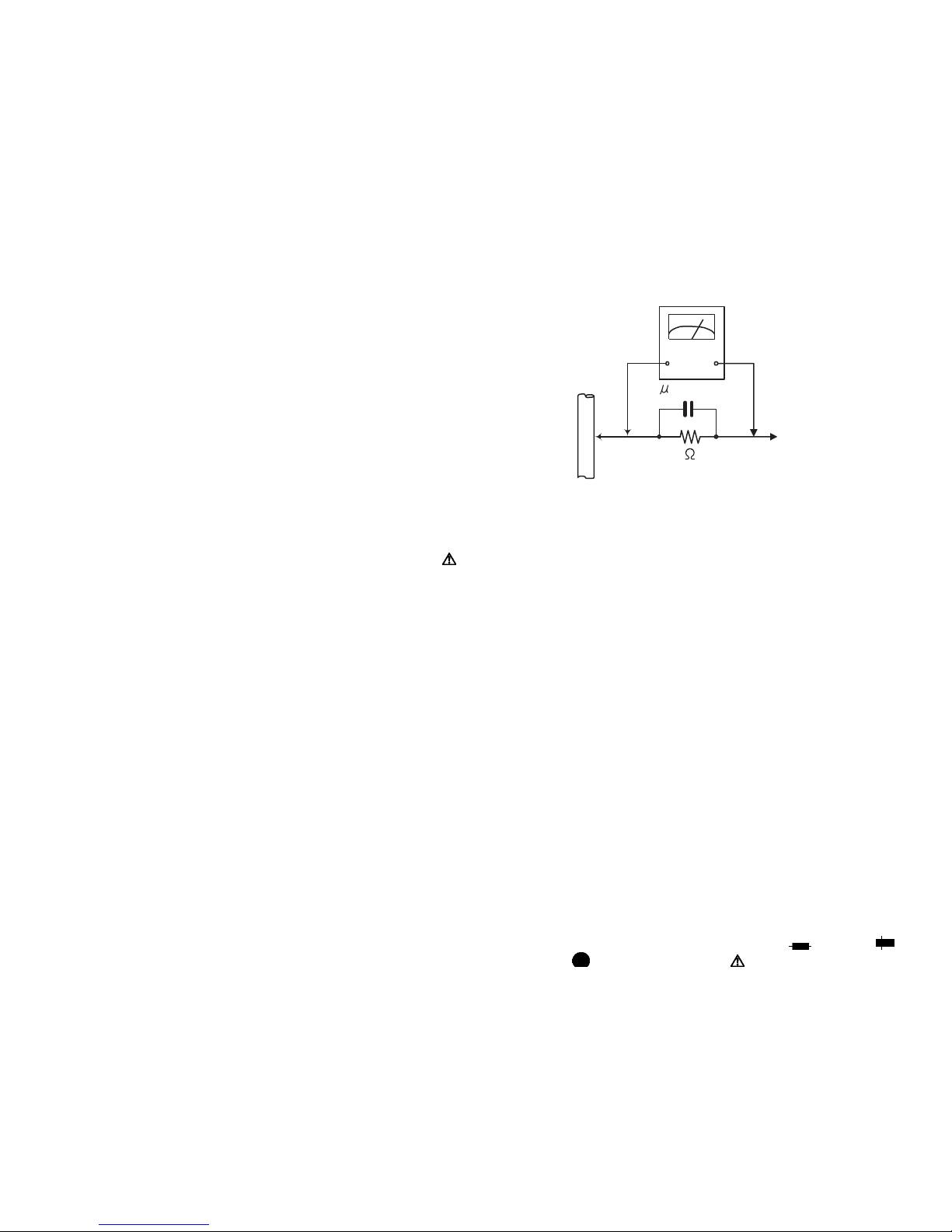
• Alternate check method
Plug the AC line cord directly into the AC outlet. Use an
AC voltmeter having, 1,000Ω per volt or more sensitivity
in the following manner. Connect a 1,500Ω 10W resistor
paralleled by a 0.15µF AC-type capacitor between an ex-
posed metal part and a known good earth ground.
Measure the AC voltage across the resistor with the AC
voltmeter.
Move the resistor connection to each exposed metal
part, particularly any exposed metal part having a return
path to the chassis, and measure the AC voltage across
the resistor. Now, reverse the plug in the AC outlet and
repeat each measurement. Voltage measured any must
not exceed 0.75 V AC (r.m.s.). This corresponds to 0.5
mA AC (r.m.s.).
AC VOLTMETER
(Having 1000
ohms/volts,
or more sensitivity)
0.15 F AC TYPE
Place this
probe on
1500 10W
Good earth ground
1.2 Warning
(1) This equipment has been designed and manufactured to
meet international safety standards.
(2) It is the legal responsibility of the repairer to ensure that
these safety standards are maintained.
(3) Repairs must be made in accordance with the relevant
safety standards.
(4) It is essential that safety critical components are replaced
by approved parts.
(5) If mains voltage selector is provided, check setting for local
voltage.
1.3 Caution
Burrs formed during molding may be left over on some parts
of the chassis.
Therefore, pay attention to such burrs in the case of preforming repair of this system.
1.4 Critical parts for safety
In regard with component parts appearing on the silk-screen
printed side (parts side) of the PWB diagrams, the parts that are
printed over with black such as the resistor ( ), diode ( )
and ICP ( ) or identified by the " " mark nearby are critical
for safety. When replacing them, be sure to use the parts of the
same type and rating as specified by the manufacturer.
(This regulation dose not Except the J and C version)
each exposed
metal part.
(No.MB519)1-3
Page 4
1.5 Safety Precautions (U.K only)
(1) This design of this product contains special hardware and many circuits and components specially for safety purposes. For con-
tinued protection, no changes should be made to the original design unless authorized in writing by the manufacturer. Replacement parts must be identical to those used in the original circuits.
(2) Any unauthorised design alterations or additions will void the manufacturer's guarantee; furthermore the manufacturer cannot
accept responsibility for personal injury or property damage resulting therefrom.
(3) Essential safety critical components are identified by ( ) on the Parts List and by shading on the schematics, and must never
be replaced by parts other than those listed in the manual. Please note however that many electrical and mechanical parts in
the product have special safety related characteristics. These characteristics are often not evident from visual inspection. Parts
other than specified by the manufacturer may not have the same safety characteristics as the recommended replacement parts
shown in the Parts List of the Service Manual and may create shock, fire, or other hazards.
(4) The leads in the products are routed and dressed with ties, clamps, tubings, barriers and the like to be separated from live parts,
high temperature parts, moving parts and/or sharp edges for the prevention of electric shock and fire hazard. When service is
required, the original lead routing and dress should be observed, and it should be confirmed that they have been returned to
normal, after re-assembling.
1.5.1 Warning
(1) Service should be performed by qualified personnel only.
(2) This equipment has been designed and manufactured to meet international safety standards.
(3) It is the legal responsibility of the repairer to ensure that these safety standards are maintained.
(4) Repairs must be made in accordance with the relevant safety standards.
(5) It is essential that safety critical components are replaced by approved parts.
(6) If mains voltage selector is provided, check setting for local voltage.
Burrs formed during molding may be left over on some parts of the chassis. Therefore,
pay attention to such burrs in the case of preforming repair of this system.
1-4 (No.MB519)
Page 5
1.6 Preventing static electricity
Electrostatic discharge (ESD), which occurs when static electricity stored in the body, fabric, etc. is discharged, can destroy the laser
diode in the traverse unit (optical pickup). Take care to prevent this when performing repairs.
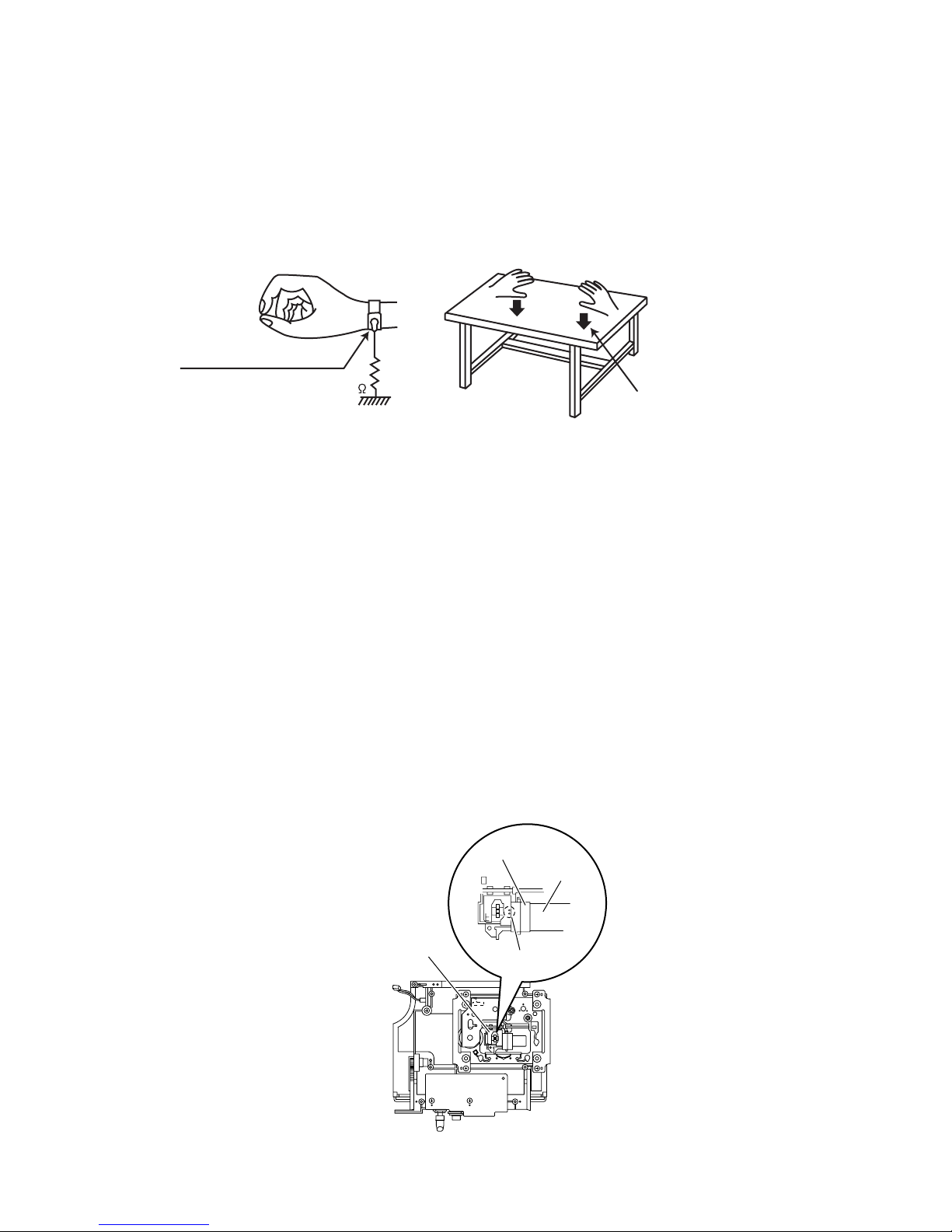
1.6.1 Grounding to prevent damage by static electricity
Static electricity in the work area can destroy the optical pickup (laser diode) in devices such as laser products.
Be careful to use proper grounding in the area where repairs are being performed.
(1) Ground the workbench
Ground the workbench by laying conductive material (such as a conductive sheet) or an iron plate over it before placing the
traverse unit (optical pickup) on it.
(2) Ground yourself
Use an anti-static wrist strap to release any static electricity built up in your body.
(caption)
Anti-static wrist strap
1M
Conductive material
(conductive sheet) or iron palate
(3) Handling the optical pickup
• In order to maintain quality during transport and before installation, both sides of the laser diode on the replacement optical
pickup are shorted. After replacement, return the shorted parts to their original condition.
(Refer to the text.)
• Do not use a tester to check the condition of the laser diode in the optical pickup. The tester's internal power source can easily
destroy the laser diode.
1.7 Handling the traverse unit (optical pickup)
(1) Do not subject the traverse unit (optical pickup) to strong shocks, as it is a sensitive, complex unit.
(2) Cut off the shorted part of the flexible cable using nippers, etc. after replacing the optical pickup. For specific details, refer to the
replacement procedure in the text. Remove the anti-static pin when replacing the traverse unit. Be careful not to take too long a
time when attaching it to the connector.
(3) Handle the flexible cable carefully as it may break when subjected to strong force.
(4) I t is not possible to adjust the semi-fixed resistor that adjusts the laser power. Do not turn it.
1.8 Attention when traverse unit is decomposed
*Please refer to "Disassembly method" in the text for the pickup unit.
• Apply solder to the short land sections before the flexible wire is disconnected from the connecto on the servo board. (If the flexible
wire is disconnected without applying solder, the pickup may be destroyed by static electricity.)
• In the assembly, be sure to remove solder from the short land sections after connecting the flexible wire.
CD pickup
Connector
Short land
section
Card wire
(No.MB519)1-5
Page 6
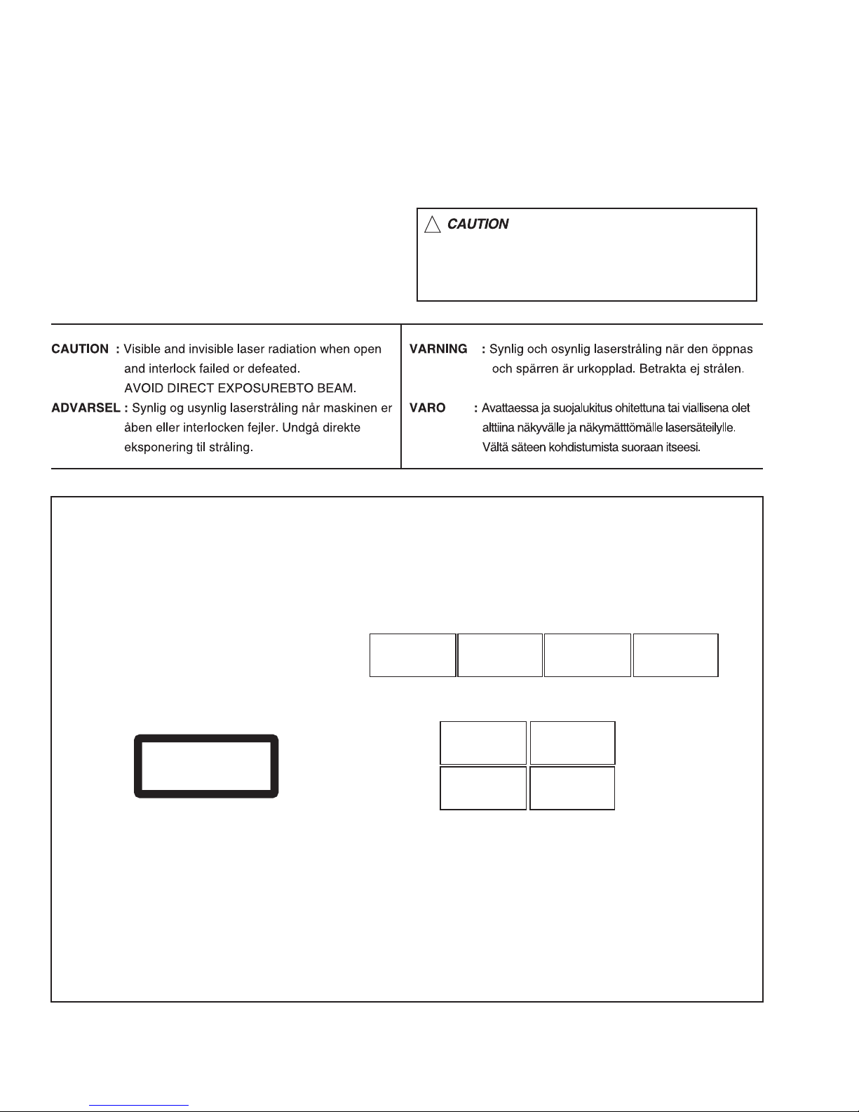
1.9 Important for laser products
!
1.CLASS 1 LASER PRODUCT
2.DANGER : Invisible laser radiation when open and inter
lock failed or defeated. Avoid direct exposure to beam.
3.CAUTION : There are no serviceable parts inside the
Laser Unit. Do not disassemble the Laser Unit. Replace
the complete Laser Unit if it malfunctions.
4.CAUTION : The CD,MD and DVD player uses invisible
laser radiation and is equipped with safety switches which
prevent emission of radiation when the drawer is open and
the safety interlocks have failed or are defeated. It is
dangerous to defeat the safety switches.
5.CAUTION : If safety switches malfunction, the laser is able
to function.
6.CAUTION : Use of controls, adjustments or performance of
procedures other than those specified here in may result in
hazardous radiation exposure.
Please use enough caution not to
see the beam directly or touch it
in case of an adjustment or operation
check.
REPRODUCTION AND POSITION OF LABELS
WARNING LABEL
CAUTION : Visible and Invisible
laser radiation when open and
interlock failed or defeated.
AVOID DIRECT EXPOSURE TO
BEAM. (e)
CLASS 1
LASER PRODUCT
ADVARSEL : Synlig og usynlig
laserstråling når maskinen er
åben eller interlocken fejeler.
Undgå direkte eksponering til
stråling. (d)
CAUTION : Visible and Invisible
laser radiation when open and
interlock failed or defeated.
AVOID DIRECT EXPOSURE TO
BEAM. (e)
VARNING : Synlig och
osynling laserstrålning när
den öppnas och spärren är
urkopplad. Betrakta ej
strålen. (s)
VARNING : Synlig och
osynling laserstrålning när
den öppnas och spärren är
urkopplad. Betrakta ej
strålen. (s)
VARO : Avattaessa ja suojalukitus
ohitettuna tai viallisena olet alttiina
näkyvälle ja näkymättömälle
lasersäteilylle. Vältä säteen
kohdistumista suoraan itseesi. (f)
ADVARSEL : Synlig og usynlig
laserstråling når maskinen er
åben eller interlocken fejeler.
Undgå direkte eksponering til
stråling. (d)
VARO : Avattaessa ja suojalukitus
ohitettuna tai viallisena olet alttiina
näkyvälle ja näkymättömälle
lasersäteilylle. Vältä säteen
kohdistumista suoraan itseesi. (f)
1-6 (No.MB519)
Page 7

SECTION 2
SPECIFIC SERVICE INSTRUCTIONS
This service manual does not describe SPECIFIC SERVICE INSTRUCTIONS.
(No.MB519)1-7
Page 8
SECTION 3
DISASSEMBLY
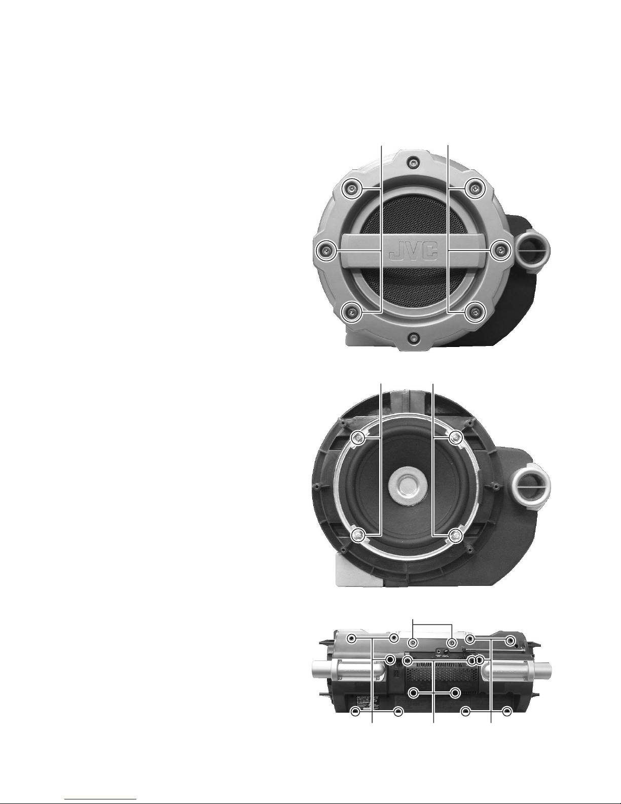
3.1 Main body
3.1.1 Removing the rear cabinet
(See Fig.1 to 3)
(1) Remove the six screws A (both side) attaching the side
protector by 6 angle wrench. (See Fig.1)
(2) Remove the eight screws B (both side) attaching the woof-
er, and then disconnect the speaker wires. (See Fig.2)
(3) Remove the ten screws C attaching the rear cabinet, and
then disconnect the grand wire from tuner board. (See
Fig.3)
AA
Fig.1
BB
Fig.2
E
1-8 (No.MB519)
C
CK
Fig.3
Page 9
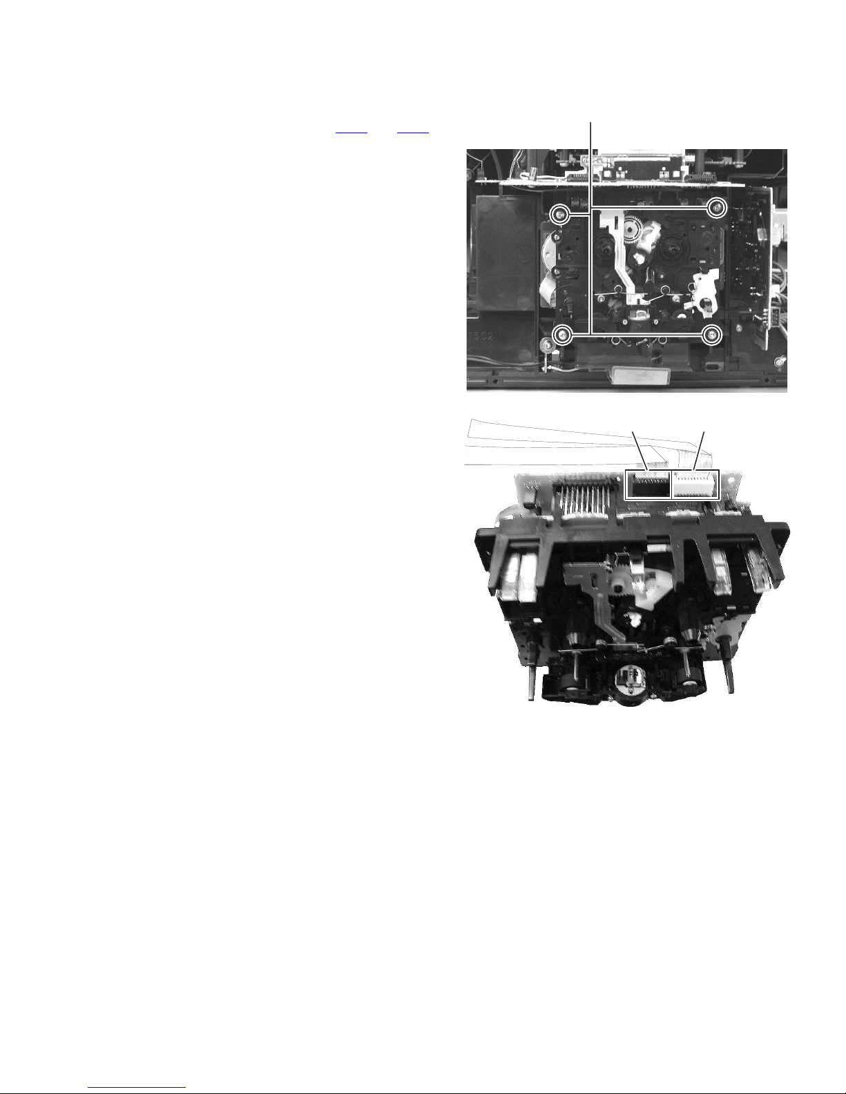
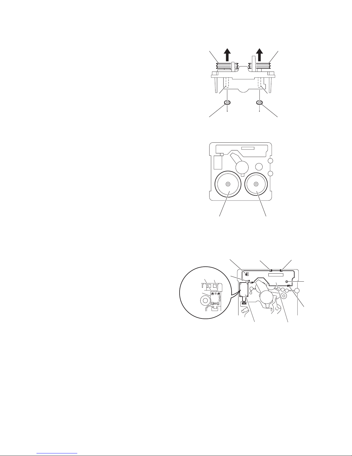
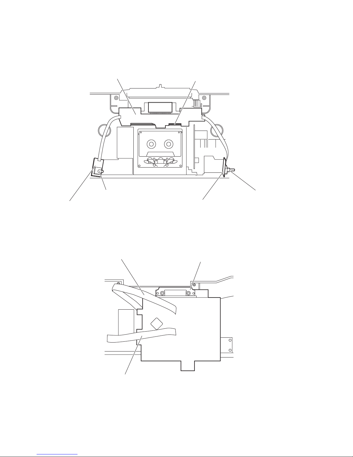
3.1.2 Removing the cassette mechanism assembly
(See Fig.4 and 5)
(1) Remove the four screws D attaching the cassette mecha-
nism. (See Fig.4)
(2) Disconnect the card wires connected to CN33
from display control board. (See Fig.5)
and CN34
D
Fig.4
CN33 CN34
Fig.5
(No.MB519)1-9
Page 10
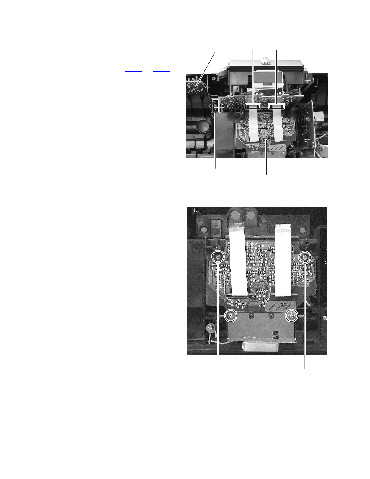
3.1.3 Removing the CD mechanism assembly
(See Fig.3 and 6)
(1) Remove the two screws E attaching the CD mechanism
assembly. (See Fig.3)
(2) Disconnect the card wire connected to CN403 from tuner
board. (See Fig.6)
(3) Disconnect the card wires connected to CN407
from equalizer amp board. (See Fig.6)
and CN408
Tuner boaard
CN407CN408
3.1.4 Removing the equalizer amp board
(See Fig.7)
(1) Remove the four screws F attaching the equalizer amp
board. (See Fig.7)
CN403
Equalizer amp board
Fig.6
1-10 (No.MB519)
FF
Fig.7
Page 11
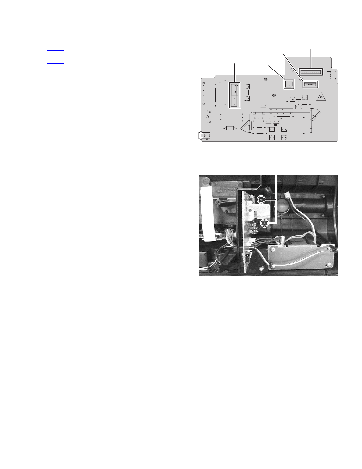
3.1.5 Removing the power supply board
(See Fig.8 and 9)
(1) Disconnect the connector wires connected to CN194
from power transformer. (See Fig.8)
CN195
(2) Disconnect the connector wires connected to CN191 and
from power amplifier board. (See Fig.8)
CN193
(3) Remove the two screws G attaching the power supply
board. (See Fig.9)
and
CN194
CN195
Fig.8
CN193
G
CN191
Fig.9
(No.MB519)1-11
Page 12
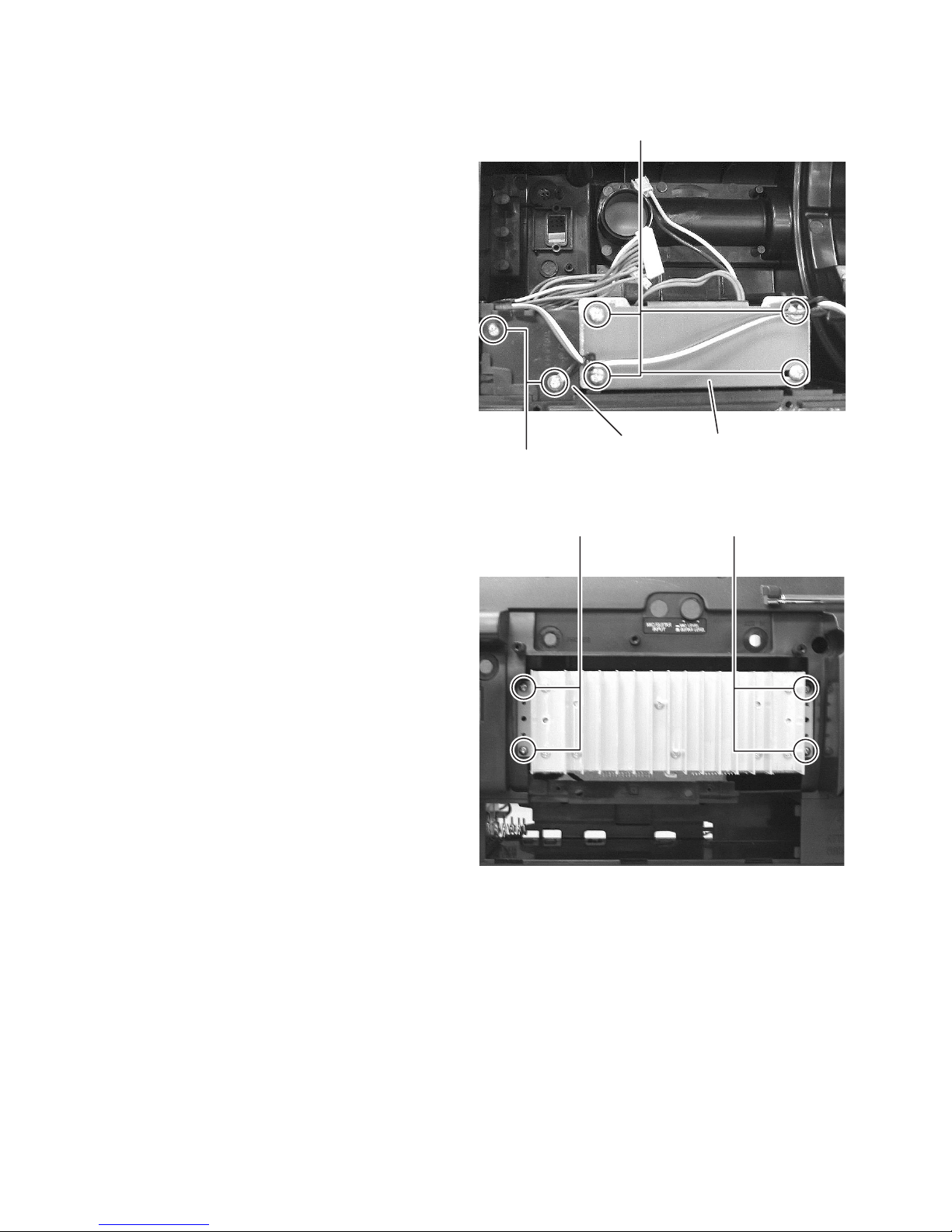
3.1.6 Removing the power transformer
(See Fig.10)
(1) Remove the four screws H attaching the power transform-
er.
3.1.7 Removing the power amplifier board
(See Fig.3, 10 and 11)
(1) Remove the two screws J attaching the cover. (See Fig.10)
(2) Remove the four screws K attaching the heat sink cover.
(See Fig.3)
(3) Remove the four screws L attaching the power amplifier
board. (See Fig.11)
H
cover power transformer
J
Fig.10
LL
1-12 (No.MB519)
Fig.11
Page 13
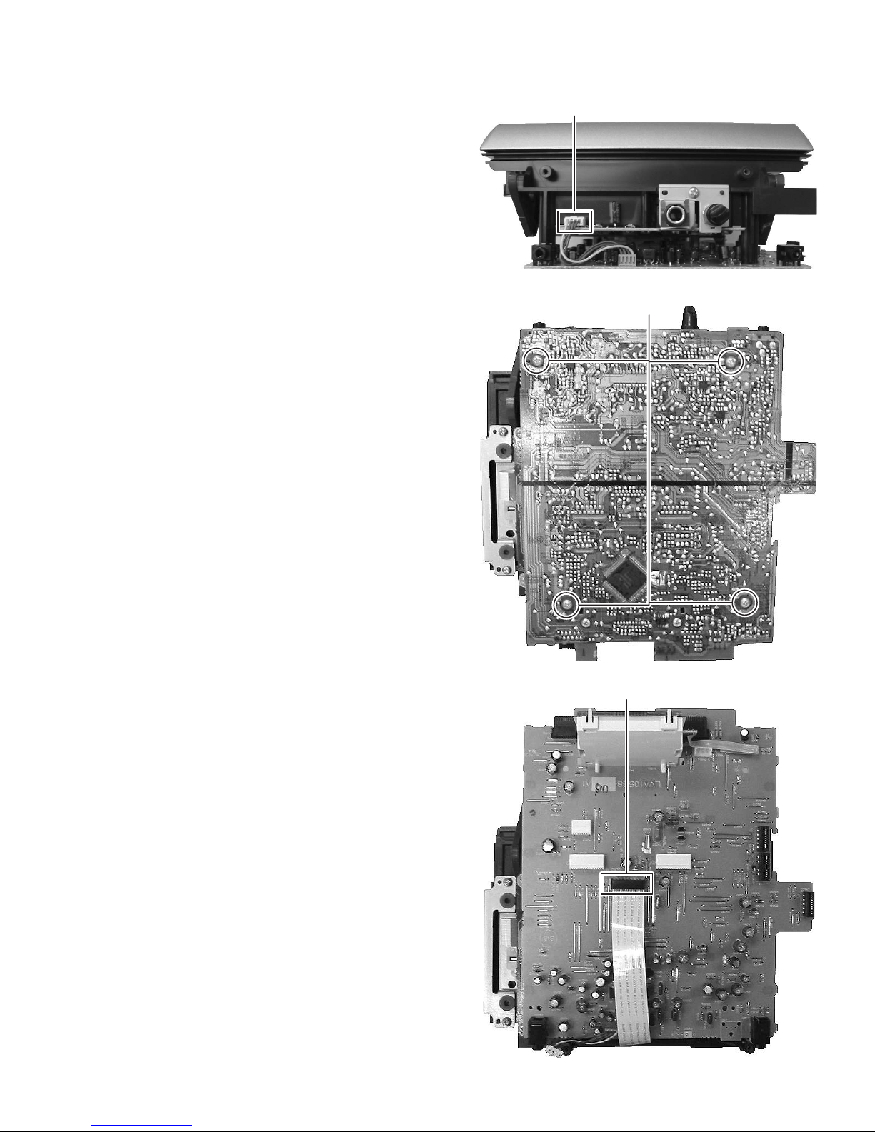
3.1.8 Removing the display control board
(See Fig.12 to 14)
(1) Disconnect the connector wire connected to CN751
guitar and mic. jack board. (See Fig.12)
(2) Remove the four screws M attaching the display control
board. (See Fig.13)
(3) Disconnect the card wire connected to CN404
servo board. (See Fig.14)
from CD
from
CN751
Fig.12
M
Fig.13
CN404
Fig.14
(No.MB519)1-13
Page 14
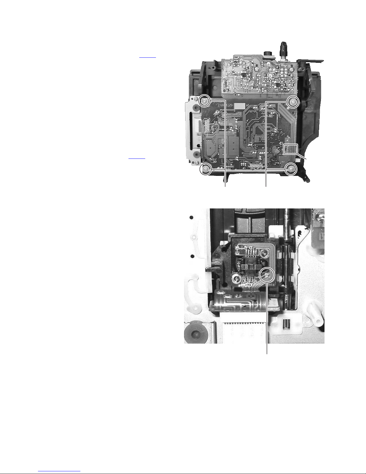
3.1.9 Removing the CD servo board
(See Fig.15 and 16)
(1) Remove the four screws N attaching the CD servo board.
(See Fig.15)
(2) Disconnect the connector wire connected to CN603 from
door switch board. (See Fig.15)
(3) Disconnect the connector wire connected to feed motor
board.
(4) Solder the short land section on the card wire of CD pickup.
(See Fig.16)
CAUTION:
• Solder the short land section on the card wire of CD
pickup before disconnecting the card wire from the
connector on the CD pickup. If the card wire is disconnected without attaching the solders, the pickup may
be destroyed by static electricity.
• When attaching the CD pickup, be sure to remove solders from the short land section after connecting the
card wire to the connector on the CD pickup.
(5) Disconnect the card wire connected to CN601
pickup.
from CD
CN603
N
Fig.15
1-14 (No.MB519)
short land section
Fig.16
Page 15
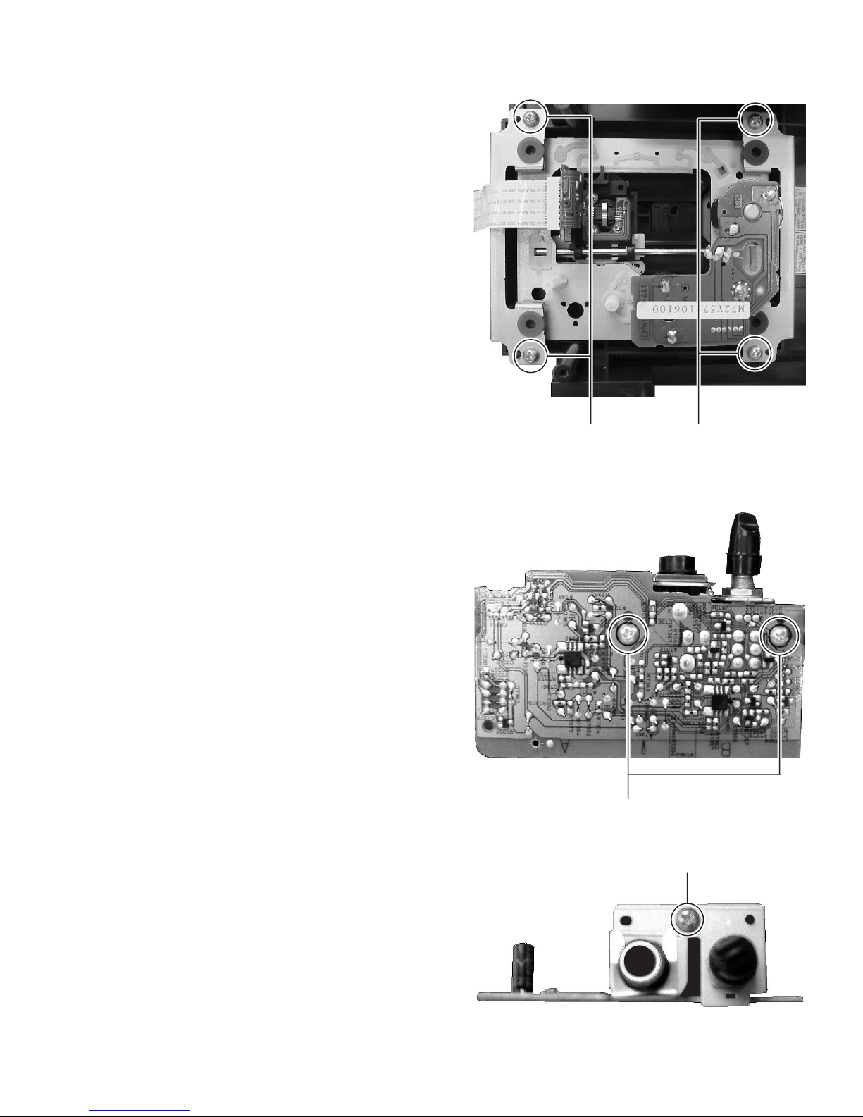
3.1.10 Removing the traverse mechanism
(See Fig.17)
(1) Remove the four screws P attaching the traverse mecha-
nism.
3.1.11 Removing the guitar and mic. Jack board
(See Fig.18 and 19)
(1) Remove the two screws Q attaching the guitar and mic.
Jack board. (See Fig.18)
(2) Remove the one screw R attaching the guitar and mic. Jack
board. (See Fig.19)
PP
Fig.17
Q
Fig.18
R
Fig.19
(No.MB519)1-15
Page 16
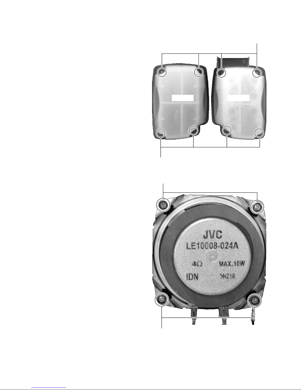
3.1.12 Removing the front cabinet
(See Fig.20 and 21)
(1) Remove the eights screws S (both side) attaching the
speaker cover. (See Fig.20)
(2) Remove the eight screws T (both side) attaching the
speaker. (See Fig.21)
S
left sideright side
S
Fig.20
T
1-16 (No.MB519)
T
Fig.21
Page 17
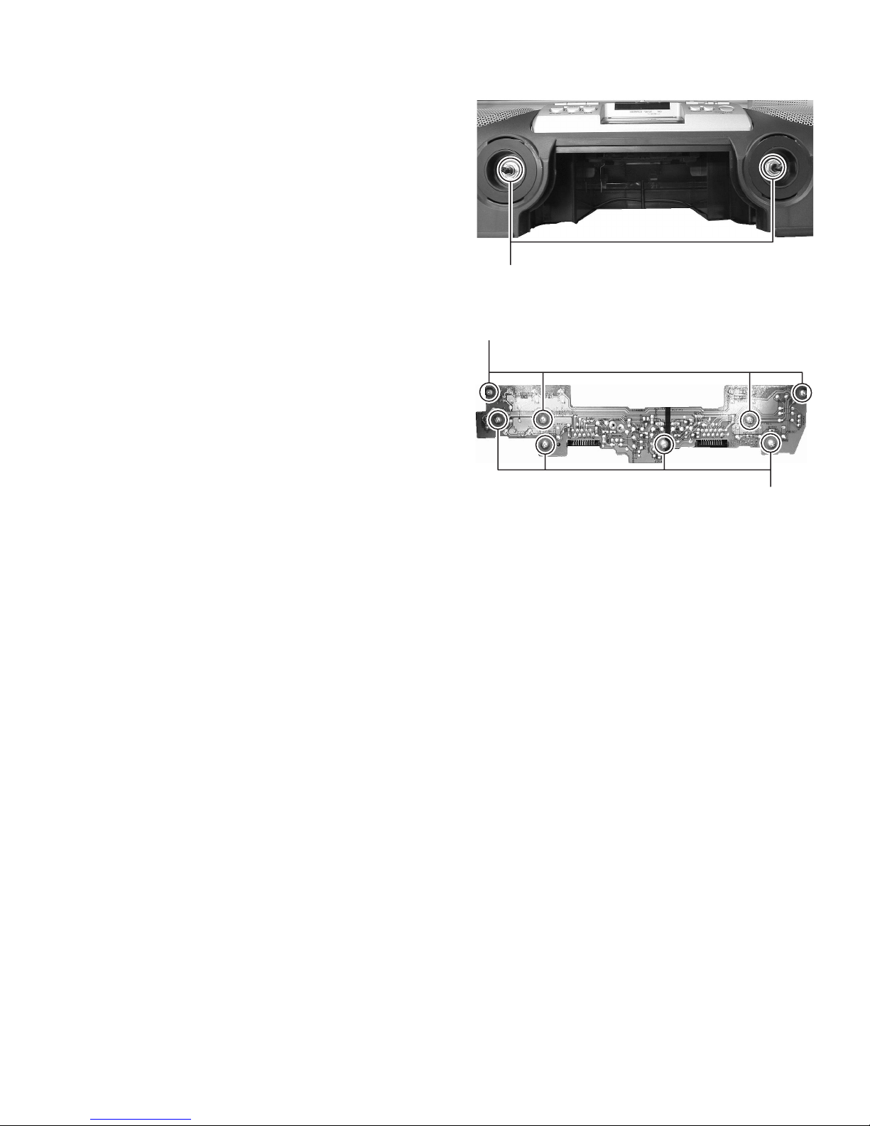
3.1.13 Removing the key board
(See Fig.22 and 23)
(1) Take off the volume and super woofer volume knob.
(2) Remove the two nuts U attaching the main volume and su-
per woofer volume. (See Fig.22)
(3) Remove the eight screws V attaching the key board. (See
Fig.23)
U
Fig.22
V
Fig.23
V
(No.MB519)1-17
Page 18
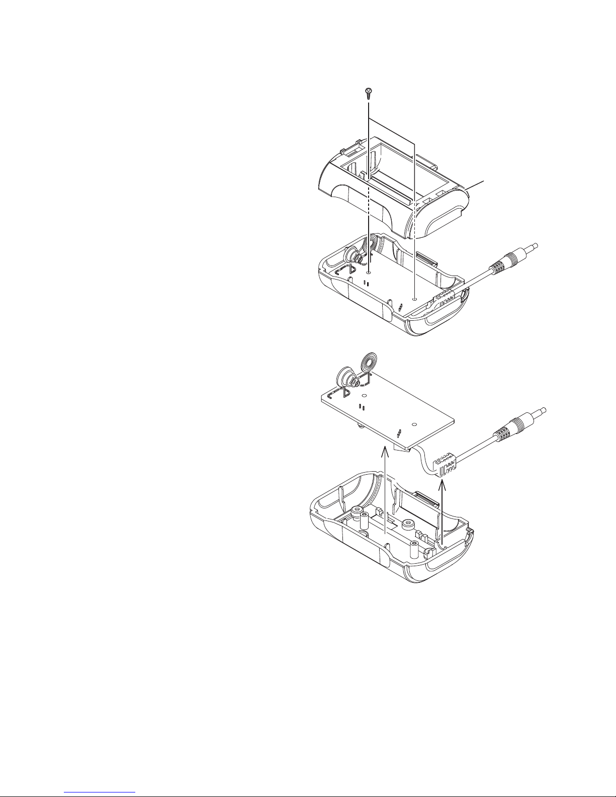
3.1.14 Removing the transmitter board
(See Fig.24 and 24)
(1) Remove the two screws W attaching the transmitter board.
(See Fig.24)
(2) Pull up the transmitter board with cable. (See Fig.24)
W
Bottom case
Fig.24
Fig.25
1-18 (No.MB519)
Page 19
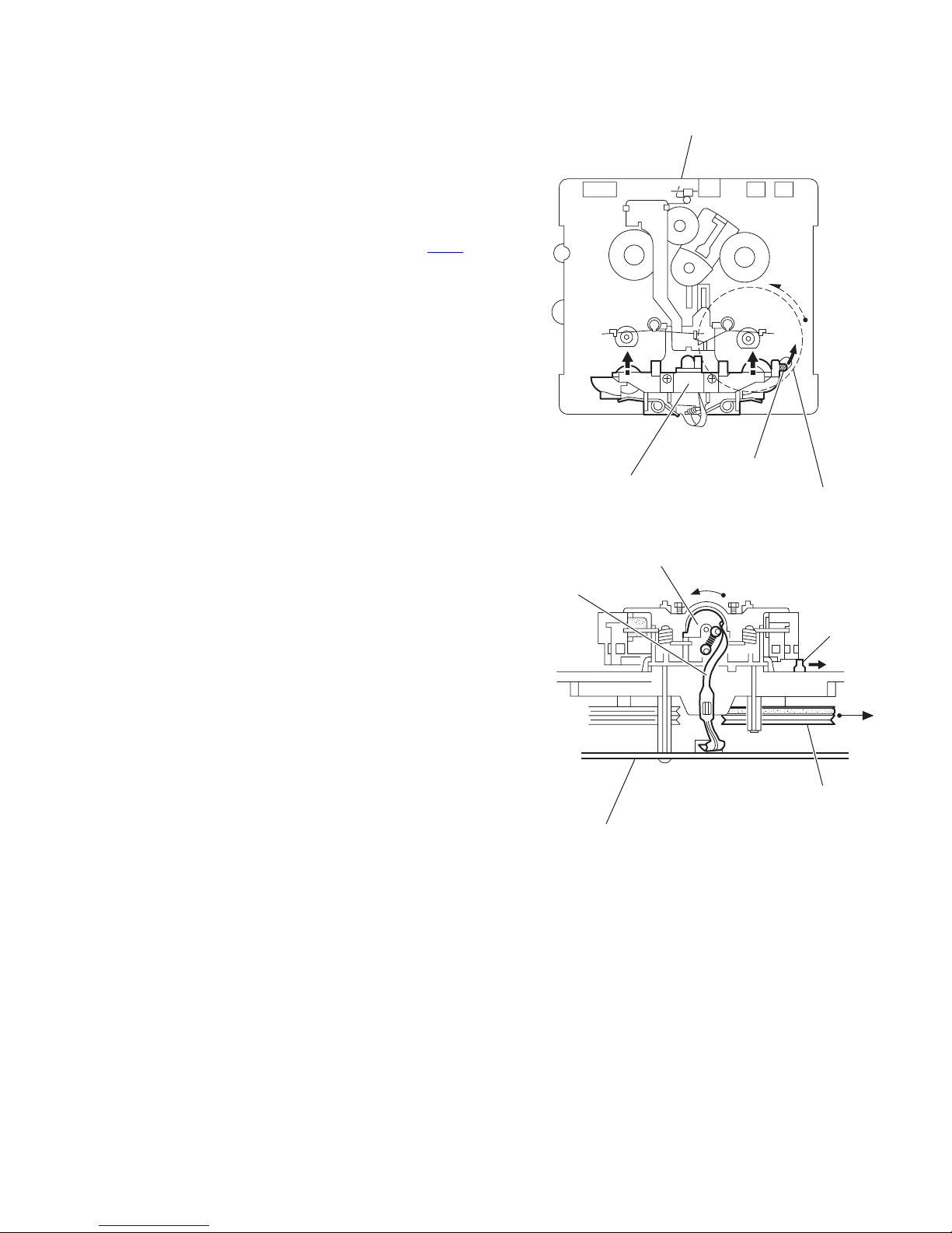
3.2 CD traverse mechanism section
• Remove the CD traverse mechanism assembly. (See "3.1.12 Removing the CD traverse mechanism assembly".)
3.2.1 Removing the CD pick
(See Figs.1 and 2)
(1) Remove the CD mechanism holders in the direction of the
arrow. (See Fig.1.)
(2) Remove the four screws A attaching the pick cover. (See
Fig.1.)
(3) Remove the insulators (brown and orange) from the CD
mechanism base assembly. (See Fig.2.)
(4) Remove the CD shaft from the CD mechanism base as-
sembly in the direction of the arrow 2 while moving the
shaft stopper in the direction of the arrow 1. (See Fig.2.)
(5) Remove the CD pick from the CD mechanism base assem-
bly.
3.2.2 Installing the CD pick
(See Figs.1 and 2)
(1) While installing the section a of the CD pick to the CD
mechanism base assembly, set the CD shaft to the section
b. (See Fig.2.)
(2) Install the insulators (brown and orange) to the CD mecha-
nism base assembly. (See Fig.2.)
(3) Attach the pick cover and CD mechanism holders. (See
Fig.1.)
CD mechanism holder
A
CD mechanism holder
Insulator (Brown)
b
Feed motor
B
Pick cover
Shaft stopper
1
A
Fig.1
Insulator (Brown)
CD shaft
2
a
CD mechanism base assembly
Insulator (Orange)
CD pick
Insulator (Orange)
Fig.2
(No.MB519)1-19
Page 20
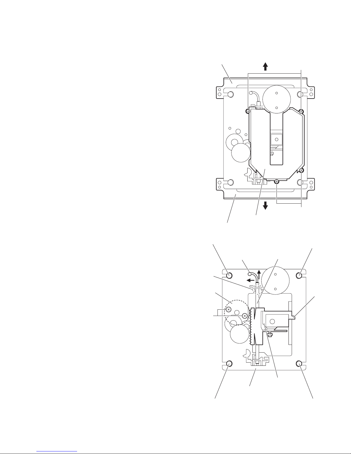
3.2.3 Removing the spindle motor and feed motor
r
(See Fig.2 to 4)
(1) Remove the two screws B attaching the feed motor. (See
Fig.2.)
(2) Remove the turn table in an upward direction and remove
the two screws C attaching the spindle motor. (See Fig.3.)
(3) From the bottom side of the CD mechanism base assem-
bly, remove the screw D attaching the spindle/feed motor
board. (See Fig.4.)
(4) Remove the solders from the sections (c, d) on the spindle/
feed motor board. (See Fig.4.)
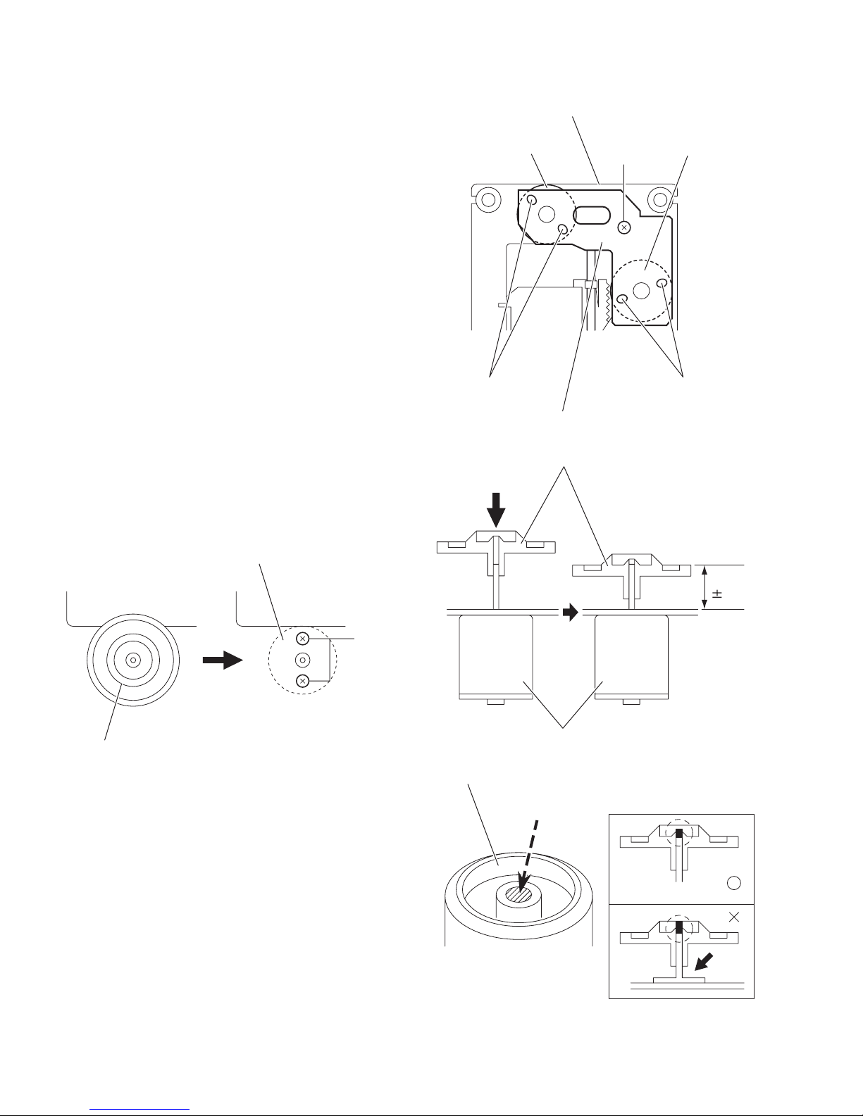
3.2.4 Installing the spindle motor and feed motor
(See Figs.3 to 6)
(1) Tighten the two screws B and two screws C to the same
torque. (See Figs.2 and 3.)
(2) Fasten the spindle/feed motor board with the screw D.
(See Fig.4.)
(3) Solder the spindle and feed motors on the spindle/feed mo-
tor board as before. (See Fig.4.)
(4) Install the turn table. When installing, press straight down
at the center of the turn table until the distance from the surface of the CD mechanism base assembly to the top of the
turn table is exactly 19.4±0.1mm. (See Fig.5.)
(5) After insertion is complete, bond the motor shaft and turn
table together. (See Fig.6.)
(6) Use 'LOCKTITE' #460 bonding agent, and apply as little as
possible. Take care not to allow any excess bonding agent
to get onto the turn table. Be extremely careful not to allow
bonding agent to adhere to the motor bearings. (See
Fig.6.)
Spindle motor
CD mechanism base assembly
Spindle motor
c d
Spindle/feed motor board
Turn table
D
Fig.4
Feed moto
19.4
0.1mm
Turn table
Fig.3
C
Spindle motor
Fig.5
Turn table
'LOCKTITE' #460
Fig.6
1-20 (No.MB519)
Page 21
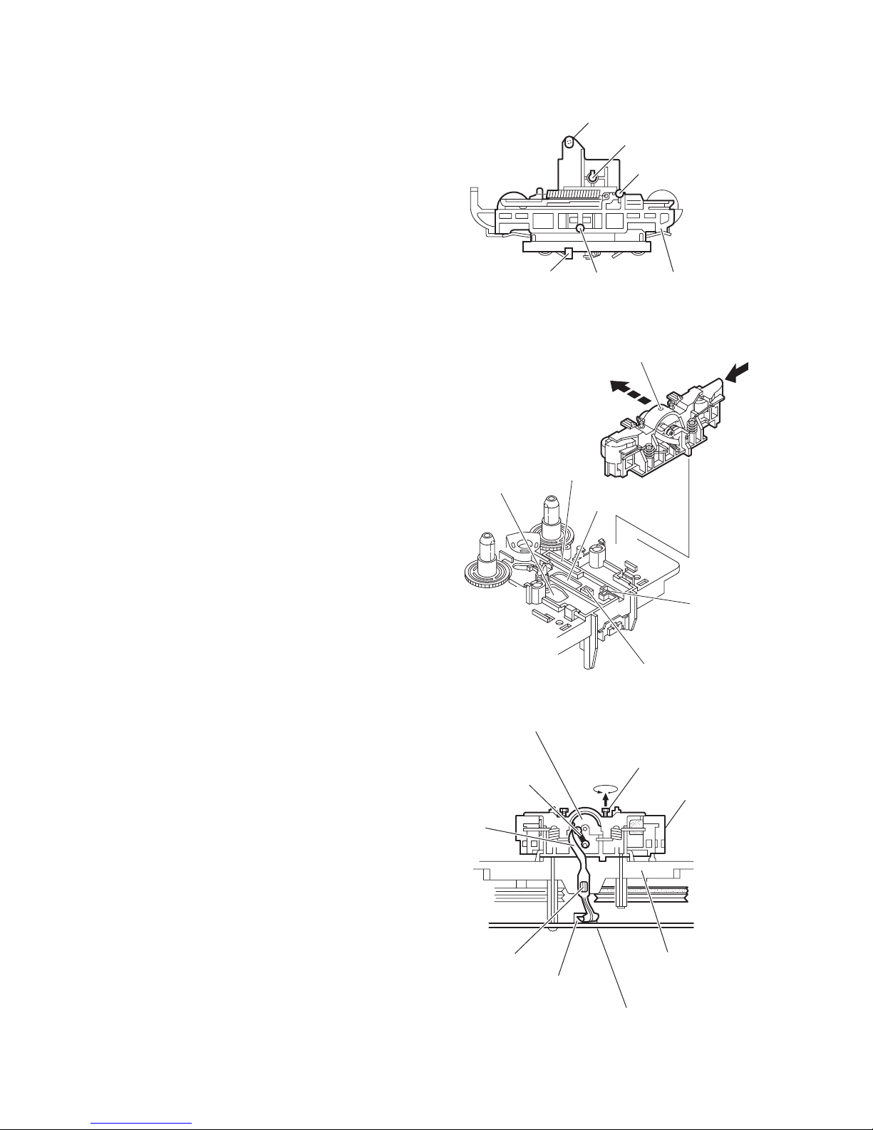
3.3 Cassette mechanism section
r
• Remove the cassette mechanism assembly. (See "3.1.3 Removing the cassette mechanism assembly".)
3.3.1 Removing the head amplifier & mechanism control board
(See Fig.1)
(1) After turning over the cassette mechanism assembly, re-
move the three screws A attaching the head amplifier &
mechanism control board.
(2) Disconnect the flexible wire from the connector CN31
the head amplifier & mechanism control board.
(3) Disconnect the head amplifier & mechanism control board
from the connector CN1
the head amplifier & mechanism control board.
Reference:
Remove the solders from the section a to remove the parallel
wire soldered to the D.C. motor as required.
on the switch board and remove
Capstan Belt
on
D.C. motor
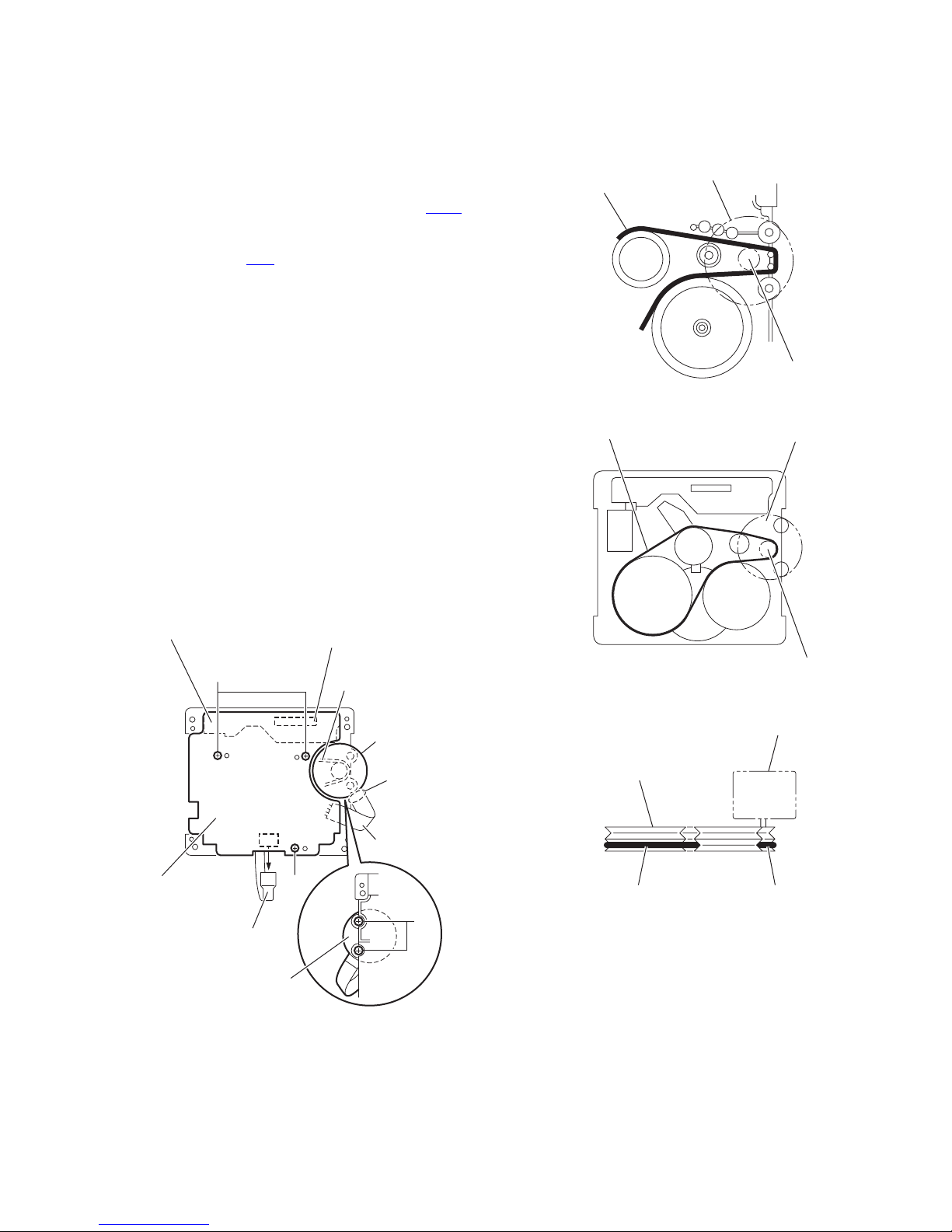
3.3.2 Removing the D.C. motor
(See Figs.1 to 4)
(1) From the bottom side of the cassette mechanism assem-
bly, remove the solders from the sections a. (See Fig.1.)
(2) From the top side of the cassette mechanism assembly, re-
move the two screws B attaching the D.C. motor. (See
Fig.1.)
(3) While raising the D.C. motor, remove the capstan belt from
the motor pulley. (See Fig.2)
Caution:
Be sure to handle the capstan belt so carefully that this belt will
not be stained by grease and other foreign matter. Moreover,
these belts should be hanged while referring to the capstan
belt hanging method. (See Figs.3 and 4.)
Switch board
A
CN1
Capstan belt
D.C. motor
a
Capstan Belt
Fly wheel (L)
Motor pulley
Fig.2
D.C. motor
Motor pulley
Fig.3
D.C. moto
CN31
Head amplifier &
mechanism control
board
Flexible wire
D.C. motor
A
Fig.1
Parallel wire
B
Capstan Belt Motor pulley
Fig.4
(No.MB519)1-21
Page 22
3.3.3 Removing the flywheels
(See Figs.5 and 6)
• Remove the head amplifier & mechanism control board and
D.C. motor.
(1) After turning over the cassette mechanism assembly, re-
move the slit washers (b, c) fixing the capstan shafts R and
L.
(2) Pull out the flywheel(R) and flywheel(L) respectively from
the bottom side of the cassette mechanism assembly.
Flywheel (L)
Capstan shaft L Capstan shaft R
Flywheel (R)
3.3.4 Removing the DC solenoid and switch board
(See Fig.7)
• Remove the head amplifier & mechanism control board and
D.C. motor.
(1) Remove the screw C attaching the switch board.
(2) Remove the pawls (d, e, f, g and h) attaching the switch
board.
(3) From the top side of the cassette mechanism assembly, re-
move the pawls (i, j) attaching the DC solenoid.
DC
solenoid
Slit
washer b
Fig.5
Flywheel (L) Flywheel (R)
Fig.6
d
e
j
i
f
Slit
washer c
g
C
1-22 (No.MB519)
h
Switch boardDC solenoid
Fig.7
Page 23
3.3.5 Removing the playback/recording head
(See Figs.8, 9, 12)
(1) While shifting the trigger arms seen on the right side of the
head mount assembly in the direction of the arrow, turn the
flywheel (L) in counterclockwise direction until the head
mount assembly has gone out with a click. (See Figs.8 and
9.)
(2) When the flywheel (L) is rotated in counterclockwise direc-
tion from the position in Fig.9 to that in Fig.12.
(3) At this position, disconnect the flexible wire (outgoing from
the playback/recording head) from the connector CN31
the head amplifier & mechanism control board. (See
Fig.12.)
(4) Remove the flexible wire from the section k. (See Fig.12.)
(5) Remove the spring from the bottom side of the playback/re-
cording head. (See Fig.12.)
(6) Loosen the reversing azimuth screw attaching the play-
back/recording head. (See Fig.12.)
(7) Take out the playback/recording head from the front side of
the head mount assembly.
Cassette mechanism assembly
on
Trigger arm
Head mount assembly
Flywheel (L)
Fig.8
Playback/recording head
Flexible wire
Head amplifier & mechanism control board
Fig.9
Trigger arm
Flywheel (L)
(No.MB519)1-23
Page 24
3.3.6 Reassembling the playback/recording head
r
(See Figs.10 to 12)
(1) Reassemble the head mount.
a) To become direction of the left side, direction lever of
the head mount assembly is maintained by the hand.
(See Fig.11.)
b) Reassemble the playback/recording head from the
front of the head mount assembly to the position as
shown Fig.10, Fig11, and Fig.12. (m', n', p' and q', r'
are set to the hole of n and p and ditches of m, q and
r and thrusting out the head mount assembly is built
in.
(2) Fix the reversing azimuth screw. (See Fig.12.)
(3) Set the spring from the bottom side of the playback/record-
ing head. (See Fig.12.)
(4) Attach the flexible wire to the section k of the chassis base
assembly. (See Fig.12.)
m'
n'
p'
q'
r'
Detection leve
Fig.10
Head mount
Assembly
p
Playback/recording head
Spring
Flexible
wire
m
n
q
r
Fig.11
Reversing azimuth screw
Head mount assembly
1-24 (No.MB519)
k
Chassis base assembly
CN31
Head amplifier & mechanism control board
Fig.12
Page 25
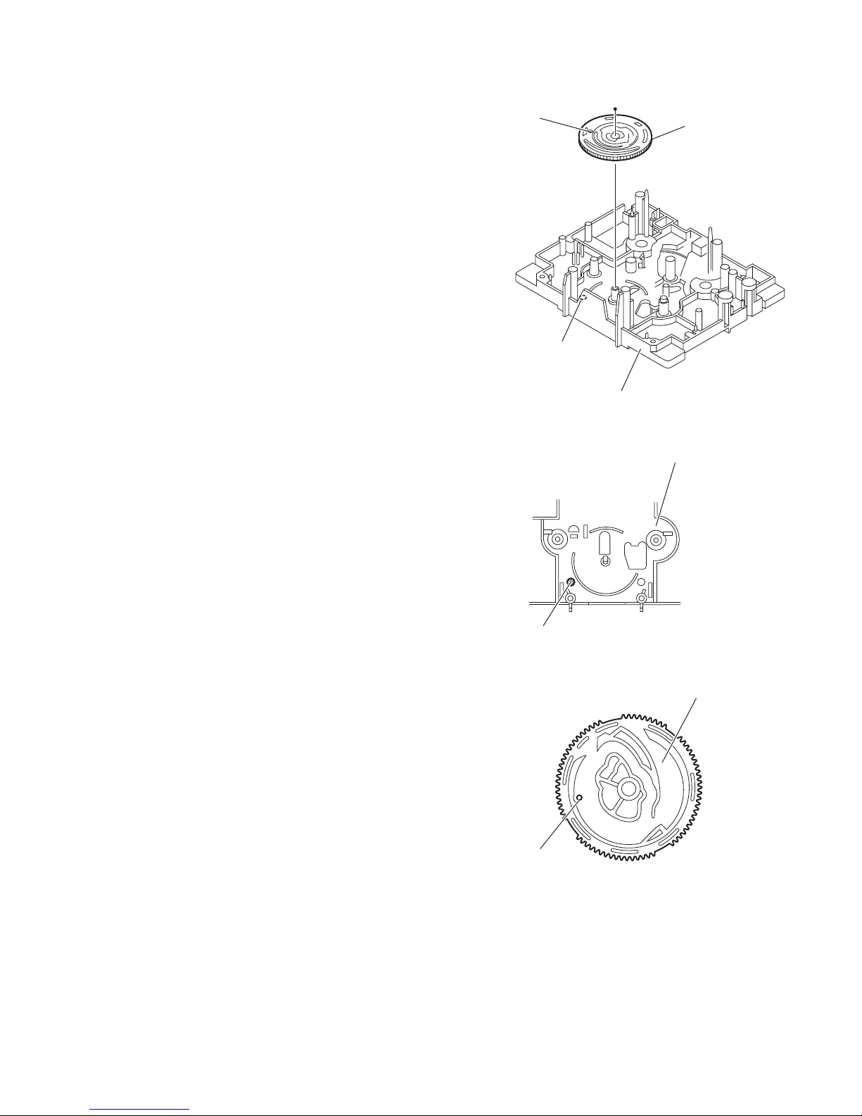
3.3.7 Reassembling the Control Cam
(See Figs.13 to 15)
The head assembly is adjusted in the direction of the left side (direction of the forward), and it inserts according to the part of the
hole s of the control cam and the section s' of the chassis base
assembly.
s (hole)
Control cam
s'
Chassis base assembly
Fig.13
Chassis base assembly
s'
s (hole)
Fig.14
Control cam (Surface)
Fig.15
(No.MB519)1-25
Page 26
SECTION 4
ADJUSTMENT
4.1 Connection of adjustment
4.1.1 Connection of cassette deck and circuit board check
Key board
Super woofer volume Main volume
Woofer volume encoder board
*Remove the key, volume encoder and woofer volume encoder boards from the front cabinet assembly
and connect them to the display control board.
Display control board
Volume encoder board
4.1.2 Connection of CD mechanism assembly check
Extension cable
Extension cable
CD mechanism assembly
1-26 (No.MB519)
Page 27
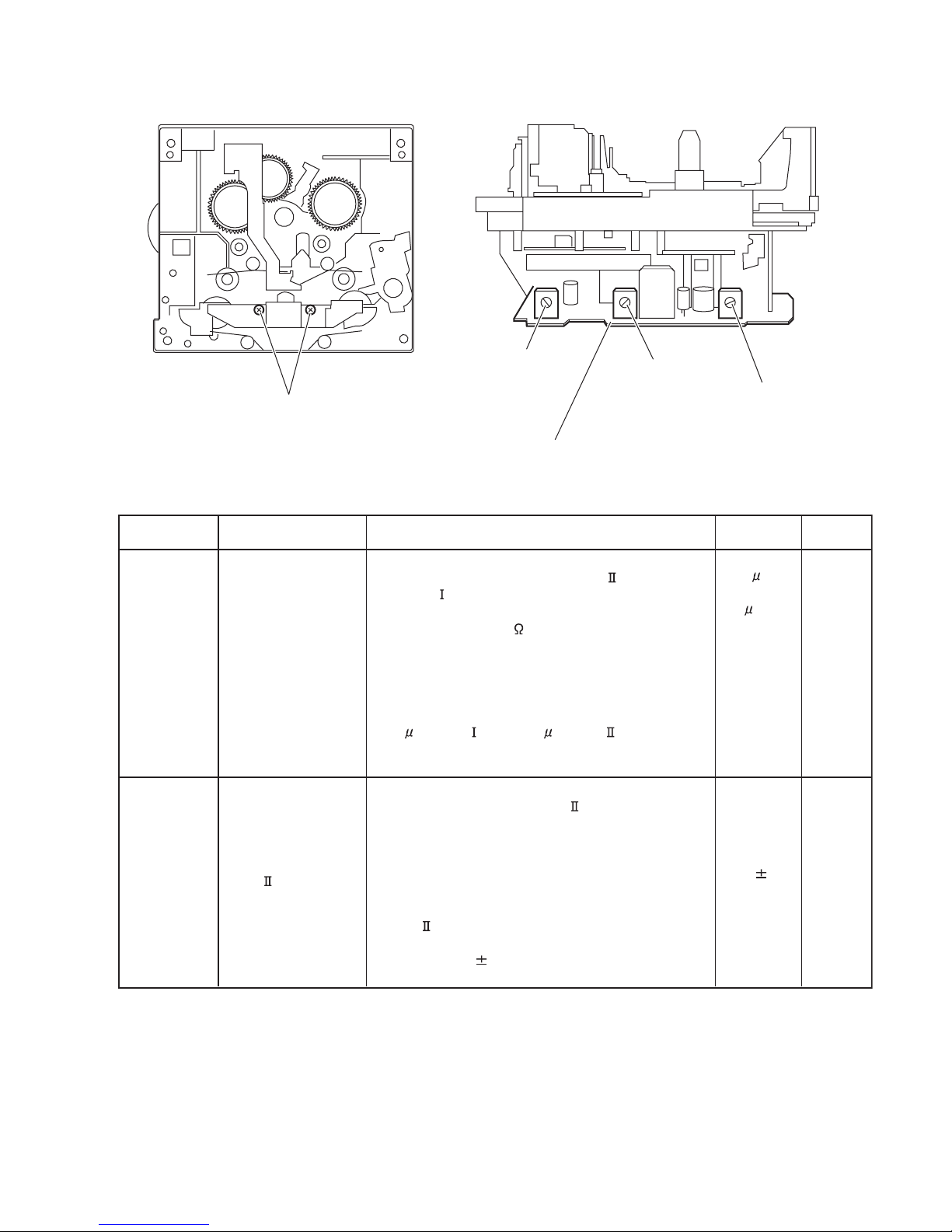
4.2 Adjustment of cassette mechanism section
4.2.1 Arrangement of adjusting points
Azimuth adjust screws
4.2.2 Electrical performance
Items
Adjustment of
recording bias
current
Measurement
conditions
*Mode :
Forward or reverse
mode
(Reference
value)
*Recording mode
*Test tape :
AC-514 and AC-225
Measurement output
terminal :
Both recording and
headphone terminals
Adjustment of
recording and
playback
Reference frequency :
1kHz and 10kHz
(REF:-20dB)
frequency
characteristics
Test tape :
TYPE AC-514
Measurement input
terminal : OSC IN
VR32
VR31
Adjustment of tape speed
Head amplifier & mechanism control board
Measurement method
1. With the recording and playback mechanism,
load the test tapes(AC-514 to TYPE and AC-225
to TYPE ),and set the mechanism to the recording
and pausing conditions in advance.
2. After connecting 100 in series to the recorder head,
measure the bias current with a valve voltmeter at
both of the terminals.
3. After resetting the [PAUSE] mode, start recording.
At this time, adjust VR31 for Lch and VR32 for Rch
so that the recording bias current values become
4.0 A (TYPE ) and 4.20 A(TYPE ).
1. With the recording and playback mechanism, load
the test tape(AC-514 to TYPE ),and set the
mechanism to the recording and pausing condition in
advance.
2. While repetitively inputting the reference frequency
signal of 1kHz and 10kHz from OSC IN, record and
playback the test tape.
3. While recording and playing back the test tape in
TYPE ,adjust VR31 for LcH and VR32 for RcH so
that the output deviation between 1kHz and 10kHz
becomes -1dB 2dB.
VR37
Standard
values
AC-225
:4.20 A
AC-514
:4.0 A
Output
deviation
between
1kHz and
10kH
:-1dB 2dB
Adjusting
positions
LcH
:VR31
RcH
:VR32
LcH
:VR31
RcH
:VR32
(No.MB519)1-27
Page 28
4.2.3 Reference values for electrical function confirmation items
Items
Recording
bias frequency
Eraser current
(Reference
value)
Measurement
conditions
*Recording and
playback side forward
or reverse
*Test tape :
TYPE AC-514
*Measurement
terminal :
BIAS TP on circuit
board
*Recording and
playback side forward
or reverse
*Recording mode
*Test tape :
AC-514 and AC-225
Measurement
terminal :
Both of the eraser
head
Measurement method
1. While changing over to and from BIAS 1 and 2,
confirm that the frequency is changed.
2. With the recording and playback mechanism, load
the test tape (AC-514 to TYPE ), and set the
mechanism to the recording and pausing conditions
in advance.
3. Confirm that the BIAS TP frequency on the circuit
board is 100kHz 6kHz.
1. With the recording and playback mechanism, load
the test tapes (AC-514 to TYPE and AC-225 to
TYPE ), and set the mechanism to the recording
and pausing condition in advance.
2. After setting to the recording conditions, connect
1M in series to the eraser head on the recording
and playback mechanism side, and measure the
eraser current from both of the eraser terminal.
Standard
values
100kHz
6kHz
TYPE
:120mA
TYPE
:75mA
Adjusting
positions
4.2.4 Tape recorder section
Items
Confirmation
of head angle
Measurement
conditions
Test tape :
TMT7036 (10kHz)
1. Playback the test tape TMT7036 (10kHz).
2. With the playback mechanism or recording &
playback mechanism, adjust the head azimuth
Measurement
output terminal :
Speaker terminal
screw so that the forward and reverse output
levels become maximum. After adjustment, lock
the head azimuth at least by half a turn.
3. In either case, this adjustment should be
Confirmation
of tape speed
Speaker R :
headphone terminal
Test tape :
VT712 (3kHz) or
TMT7036 (3kHz)
performed in both the forward and reverse
directions with the head azimuth screw.
<Constant speed>
Adjust VR37 so that the frequency counter reading
becomes 3,010Hz 15Hz when playing back the
test tape VT712 (3kHz) with the playback
Measurement
output terminal :
mechanism or playback and recording mechanism
after ending forward winding of the tape.
Headphone terminal
4.2.5 Reference values for confirmation items
Items
Wow & flutter
Measurement
conditions
When the test tape VT712 (3kHz) has been played
back with the playback mechanism or recording and
playback mechanism at the beginning of forward
winding the frequency counter reading of wow & flutter
should be 0.25% or less (WRMS).
Measurement method
Measurement method
Standard
values
Maximum
output
Tape speed
of decks
: 3,010Hz
15Hz
Standard
values
0.25% or
less
(WRMS)
Adjusting
positions
Adjust the
head
azimuth
screw only
when the
head has
been
changed.
VR37
Adjusting
positions
Both the
playback
and
recording
& playback
mechanism
1-28 (No.MB519)
Page 29
SECTION 5
TROUBLE SHOOTING
5.1 Maintenance of laser pickup (CD)
(1) Cleaning the pick up lens
Before you replace the pick up, please try to clean the lens
with a alcohol soaked cotton swab.
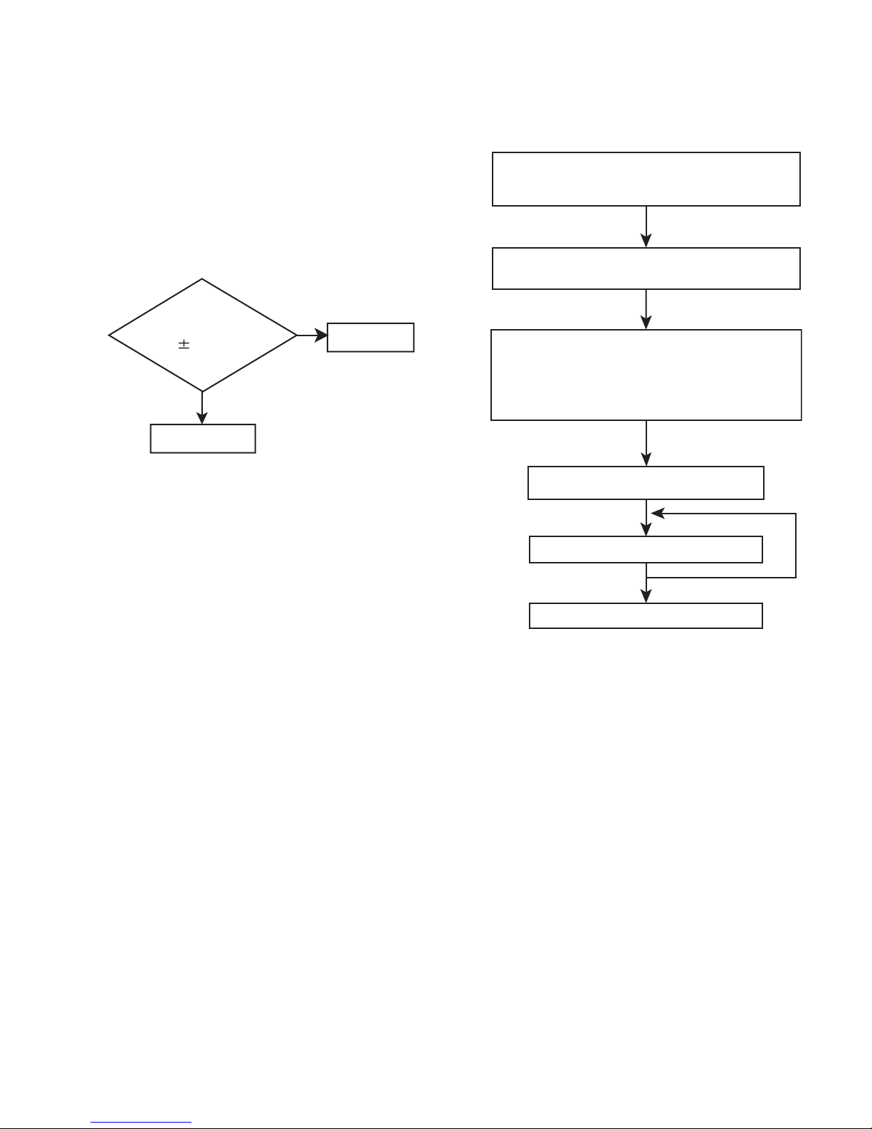
(2) Life of the laser diode
When the life of the laser diode has expired, the following
symptoms will appear.
• The level of RF output (EFM output : ampli tude of eye
pattern) will below.
Is the level of
RFOUT under
1.25V 0.22Vp-p?
YES
O.K
(3) Semi-fixed resistor on the APC PC board
The semi-fixed resistor on the APC printed circuit board
which is attached to the pickup is used to adjust the laser
power. Since this adjustment should be performed to
match the characteristics of the whole optical block, do not
touch the semi-fixed resistor.
If the laser power is lower than the specified value, the laser diode is almost worn out, and the laser pickup should
be replaced.
If the semi-fixed resistor is adjusted while the pickup is
functioning normally, the laser pickup may be damaged
due to excessive current.
NO
Replace it.
5.2 Replacement of laser pickup (CD)
Turn off the power switch and, disconnect the
power cord from the ac outlet.
Replace the pickup with a normal one.(Refer
to "Pickup Removal" on the previous page)
Plug the power cord in, and turn the power on.
At this time, check that the laser emits for
about 3seconds and the objective lens moves
up and down.
Note: Do not observe the laser beam directly.
Play a disc.
Check the eye-pattern at TP1.
Finish.
(No.MB519)1-29
Page 30

Victor Company of Japan, Limited
Audio/Video Systems Category 10-1,1chome,Ohwatari-machi,Maebashi-city,371-8543,Japan
(No.MB519)
Printed in Japan
VPT
Page 31

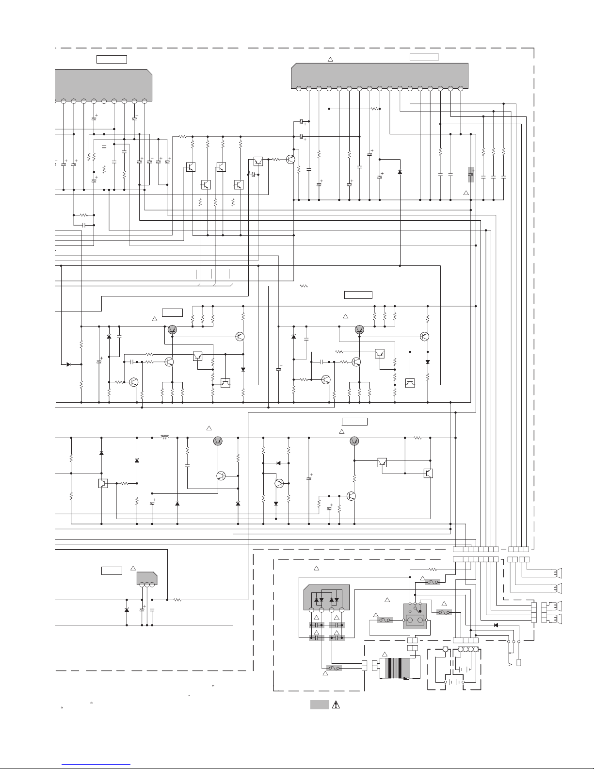
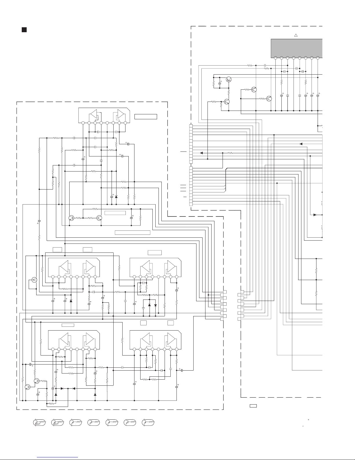
SCHEMATIC DIAGRAMS
POWERED WOOFER CD SYSTEM
RV-NB10BJ,RV-NB10BC,RV-NB10BB
RV-NB10BE,RV-NB10BEN,RV-NB10BEV
RV-NB10WJ,RV-NB10WC,RV-NB10WB
RV-NB10WE,RV-NB10WEN
CD-ROM No.SML200603
Lead free solder used in the board (material : Sn-Ag-Cu, melting point : 219 Centigrade)
Contents
Block diagrams
Standard schematic diagrams
Printed circuit boards
COPYRIGHT 2006 Victor Company of Japan, Limited.
2-1
2-3
2-29 to 38
No.MB519SCH
2006/3
Page 32

In regard with component parts appearing on the silk-screen printed side (parts side) of the PWB diagrams, the
parts that are printed over with black such as the resistor ( ), diode ( ) and ICP ( ) or identified by the " "
mark nearby are critical for safety.
Page 33

< MEMO >
Page 34

Q
Block diagram
TO
TP1
FM ANT
TO
TP1
FM ANT
CD
PICK UP
TRACKING
& FOCUS
COIL
REST SW
SPINDLE
& FEED
MOTOR
S2521
CDDOOR SW
Head amplifier section
REC/PB
ERASE
HEAD
CN31
Reel pulse / Switch section
Tuner section
AM ANT
FOR Area suffix E/B/EN/EV
Q2 to Q6,Q14
MW/LW SW
FM RF/IF/DET/MPX
AM RF/IF/DET
Tuner section FOR Area suffix J/C
FM RF/IF/DET/MPX
AM ANT
IC1
AM RF/IF/DET
CD control section
TBAL,FBAL
TE,FE
CN1
M
GCTL
/RFDET
OFT,BDO
ARF,RFENV
/CAS
/RAS
/WE
FW31
CN32
CN601 FW602
FW256
CN603
L+,R+
L-,R-
E
VR31,VR32
REC/PLAY
FREQUENCY
RESPONSE Adj.
IC1
REEL
PULSE
SW1,SW2
SW4 to SW6
SWITCH
A,B
C,D
E,F
LD,MD
T+/F+/-
SM+/FM+/-
REST
CDDOOR
IC31
HEAD SW
L301
BIAS OSC
SOLENOID
PHOTO
PHOTO+B
RREC,FREC
PLAY,TAPE
70u
IC601
RF & SERVO
AMP.
IC801
FOCUS
TRACKING
FEED
SPINDLE
BTL AMP.
DRMUTE
PC2
IC251
UNIT
MICON
RECH
Q302 to Q305
Q321,Q323
BIAS OSC/CONT.
Q306 to Q309
BEAT CUT SW
SOL
IC2
LCH,RCH,MPX
FEED
SPINDLE
TRD,FOD
AD0 to AD10
D0 to D3
IC682
IC681
RECB
BIAS1
BIAS2
Q371,Q372
MB
MOTOR
LCH,RCH,MPX
IC3
PLL
DATA,CLOCK,PERIOD
IC2
PLL
IC651
DIGITAL
SERVO
&
PROCESSOR
IC671
DRAM
/DCAS
/DRAS
CASCNT
RASCNT
/DWE
WECNT
Q102,Q202,Q301
REC EQ.
Q101,Q201
PB EQ.
IC32
PB/REC AMP.
RMUTE
IC33
SERIAL TO
PARALLEL
PORT
EXTENSION
MOTOR
Q375,Q376
SOLENOID
DRIVE
VR37
MOTOR
SPEED Adj.
DRIVE
6V
DATA,CLOCK
PERIOD
6V
OUTL
OUTR
TXTD,TXTCK
/RST_DSP
MON,FLAG
DQSY,BLKCK
MLD,MDATA
STAT,MCLK
TXD0
RXD0
/RESET
70u
RECL
RECR
PBL
PBR
SDATA
SCK
STTA
SOLCTRL
SOL
CN1
CN1
SOL
PLAY
PHOTO
KEY1
System control / Function amplifier section
TDATA
TUCK
Q3361
Q3362
MPX
PERIODE
FTUTUB
CN403
TUNER
SW
CN404
CN651
CDSTAT,CDCMND,CDBEAT
CDRESET,CDDOORSW
DI901
LCD
Q9004
BACK
TUL,TUR
CDL,CDR
IC401
FUNCTION
AMP
LCDSDAT,LCDSCL
LCDCS,LCDRS
LCDXRESET
Q9003
SW5V
CONT.
BCTL
BUP
UP
IC902
RESET
IC904
RESET
E2DATA
E2CLK
IC901
SYSTEM
MICON
EEPROM
X9002
Q9001
Q9002
CLOCK
SHIFTER
OSC1
OSC2
BEAT
X9001
XI
XO
CLOCK
PBMUTE
CN405
CN34
Q4102,Q4202
PB MUTE
CN33
SCK,
PLAY
PHOTO,TAPE0
SDATA,STTA
CN406
Q3671
Q3672
SW9V
POUT
SAFETY
SW
IC551
CD3.3V
CD3.3SAFETY
REG.
LPB,RPB
LREC,RREC
KEY
SCT1
VOLW1,VOLW2
VOL1,VOL2
REM,PIN
SMUTE
2-1
Page 35

section
EC
OLW2
L2
Q5101
Q5201
FET
VOL
TRE
BASS
SMUTE,REGSAFETY,POUT
IC831
Q8351 to Q8354
HIGH CONT.
AMP
LED1,ACS
AC/DC
Q3791
INV
Q3571
Q3572
LAMP
CONT.
FW401
FW402
D3571
D3572
Operation switch section
CN901 CN902
CN251
CN252
Q4101,Q4201
AUX MUTE
IC501
E.VOL.
S2513
POWER
PIN
Q4301
FAUX
IC603
HP AMP
Q6151
OUTL
Q6251
OUTR
Q6351
SMUTE
MUTE
WLC
Q6401
SW
TO
CD6V
REG.
AC/DC
BUP,FCD
BATT1
WVOL1
WVOL2
WVOL3
CD6.5SAFETY
Q3192
Q3194
CD SW
Q3302
SLC
MB
SW9V
REG.
REMOCON
REM
D2502,Q2501
STAND BY
AC/DC
Q6150
Q6250
HP
MUTE
IC390
US6V
US 6V
REG.
FCD,CDREGSAFETY
+B
Q3492
SW9V
SW9V
REG.
POUT
+B
IC903
S2501 to S2510
OPERATION
J4301
AUX
FW403
SIG
JACK JACK
CN751
J6301
HEADPHONE
CN407
CN601
Q6350
MUTE
CN408
CN602
BATT
+B
POUT
+B
D2503,D2504
Q2502,Q2503
RED/GREEN
S2512
SWITCH
KEY
Microphone / Guitar amplifier section
IC752
DETECTOR
SIG
BUFF. AMP
Q7358,Q7359
MIC MUTING
DRIVE
IC751
MIC/GUITAR
AMP
Q7355,Q7356
MIC/GUITAR
EQ SW
Q7360
Q7351 to Q7353
Super extra bass sectionPower amplifier section
CN603
CN604
WLC
Q6308
INL,INR
WOUT
SW
SMUTE
Q6303
MUTE
Q6304
WVOL1
Q6305
WVOL2
Q6306
WVOL3
Q6307
SW
REGSAFETY
FW602
TO
WOOFER
SPEAKER
FW601
CN191
Power supply
section
L+/R+/+B
BUP
AD/DC
D1901
DIODE
BUP
AC/DC
POUT
OUTL
OUTR
AHB.C
IC301
WOOFER
AMP
IC601
L/R
POWER
AMP
Q6301
Q6302
BRIDGE
CN195
SCT1
LED1
ACS
Q2504
Q2505
SMUTE
FW251
FW253
FW252
FW254
VOL1
VOL2
VOLW1
VOLW2
T1901
TRANS.
VOLUME
VOLUME
VR731
MIC/GUITAR
SW
MIC/GUITAR
GAIN CONT.
INL/R
OUTL/R
IC801
BASS
WOUT
BOOST
IC704
HPF
& LPF
IC701 to IC703
INPUT AMP
PHASE AMP
COMP AMP
CN194
VR901
VR902
J7351
Q8101
Q8201
BASS
BOOST
CTL
AHB.C
CN192
TO
FULLRANGE
SPEAKER
J1902 CN193
BATTERY
IN
J1901
AC IN
MIC/
GUITAR
JACK
2-2
Page 36
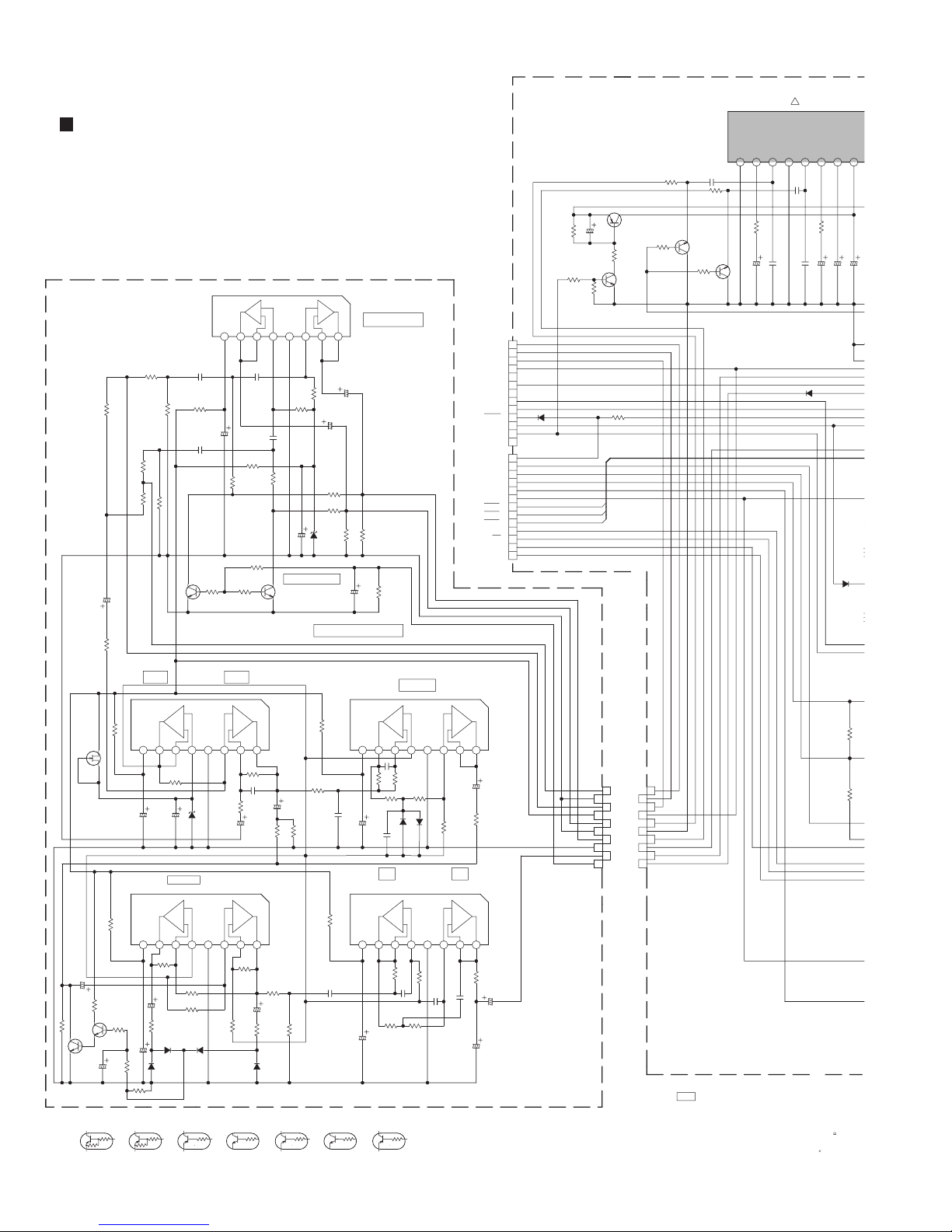
Standard schematic diagrams
O
1
Primary section (for J,C)
ACSPWB
C7311
4.7/50
2K
R7319
0V
0V
100K
R5207
0.47/50
C5308
47K
R7301
100R7303
Q7303
2SK301/R/-T
D
G
S
100
R7318
220
Q7302
R7320
KTC3199/GL/-T
9.1V
R7321
0V
Q7301
220K
KTC3199/GL/-T
0V
C7312
R7322
1/50
TABLE1 DIGITAL TRANSISTOR
10K
10K
R8201
3.3K
R8101
R5107
1/2Vcc INPUT
Vcc
8.8V
C7301
Vcc
8.7V
C7313
R7323
100/16C7314
56K
D7301
10K
10K
KRA102M-TKRC102M-T
C8201
0.056
R8321
2.7K
100
R8202
C8101
0.056
3.3K
2.7K
100K
R8102
0V
0V
Q8201
KTC3199/GL/-T
IC701
+
4.6V
4.6V
4.4V
R7305 390K
220K
100/16
C7305
4.7/50
D7307
COMP AMP
BA15218NIC703
++
--
2.8V
4.6V
4.6V
R7324
10K
R7325
10K
R7326
4.7/50
15K
1K
D7303
D7302
1SS133-T2
1SS133-T2
1SS133-T2
R7342
33K
10K
KRA111M-T
C8322
R8211
0V
47K 47K
BA15218N
GND
0V
MTZJ4.3B-T2
GND
0V
BA15218NIC801
+
-
VCC
8.8V
47/25
3.8V
4.2V
4.2V
C8202
0.056
C8102
R8301
1K
R8203
R8103
3.9K
R8327
220K
0V
R8111
0V
Q8101
GND
0V
R8104
0.056
3.9K
BASS BOOST CTL
0V
KTC3199/GL/-T
+
-
4.2V
3.8V
100K
R8204
C8103
100K
47/25
R8205
R8105
47/25
MTZJ4.3B-T2
D8301
C8301
BASS BOOST
12345678
4.2V
C8203
47/25
3.3K
3.3K
10K
10K
R8207
R8107
1/50
470K
C8303
R8302
SUPER EXTRA BASS
PHASE AMP
BA15218NIC702
+
_-
12345678
3.7V
4.5V
4.6V
R7307
C7303
3.3P
R7308
C7324
100K
C7302
0.47/50
R7317
12345678
4.5V
4.1V
5.3V
R7327
1M
R7330
3.9K
C7316
4.7/50
3.3K
1K
R7328
R7329
D7304
1SS133-T2
10K
KRC111M-T
KRA114M-T KRC114M-T
R7310
R7309
33K
4.7/50
10K
100K
R7343
2.2K
R7331
47K 47K
100
0.27
C7306
100
R7332
C7317
0.1
Vcc
C7308
4.6V
8.8V
0.01
R7311
180K
R7313
100K
C7310
0.015
C7309
100/16
HPF LPF
Vcc
8.8V
4.6V
4.6V
R7333
R7334
24K
100/16
C7318
4.7K
KRA110M-T
++
--
GND
0V
4.6V
4.6V
27K
R7314
R7312
100K
D7306
1SS133-T2
1SS133-T2
D7305
BA15218NIC704
--
GND
0V
4.2V
27K
82K
R7338
C7319
C7320
0.1
0.039
R7336
24K
4.3V
100K
R7316
++
4.3V
C7321
OUTL
AG
OUTR
SW9V
NC
WLC
NC
CN601
MG
QGF1205F1-13
MB
SMUTE
REGSAFETY
POUT
NC
MUTE
FCD
CDREGSAFETY
CD6V
DG
US6V
WVOL1
WVOL2
CN602
WVOL3
BUP
QGF1205F1-13
AC/DC
TO FUNCTION PWB(CN408) TO FUNCTION PWB(CN407)
ANTG
BATT
12345678
4.6V
4.6V
C7307
4.7/50
100K
R7344
12345678
4.6V
4.6V
2.2K
R7339
C7323
0.15
10/50
C7322
1/50
!
TA8223KIC601
2
0V0V0V
120
150P
C6102
100/25
CD STOP MODE
GND
D6301
C6201
0.22
1
R6202
150P
100/25
C6202
C6203
1SS133-T2
RESISTORS ARE
SW
NFBININ
RF
0.6V
10.1V
19.3V
120
C6302
10/50
C6301
220/25
R3508
D3493
1SS133-T2
R3507
2.2K
R3204
10K
R3203
V
GND
NFB
15 14 13 12 11 10 9 8
0V
R6101
C6101
27K
R6201
19.3V 19.3V
Q6301
2SA952/LK/-T
18.6V
3.3K
220/10
C6306
R6301
2.2K
R6302
0.7V
R6304
2
4
6
8
10
CN604
QGB1214J1-10S
0V
Q6302
0V
KTC3199/GL/-T
100K
R6325
15K
INL
1
AG
INR
3
SU9V
OUTL
5
AG
OUTR
7
WG
WOUT
9
AHB.C
R6303
5.6K
1
2
3
4
5
6
7
8
9
D6302
10
1SS133-T2
11
12
13
1
2
3
4
5
6
7
8
9
10
11
12
13
Q6101
0V
R6105
0V
KTC3203/OY/-T
4.7K
0V
R6205
4.7K
1
2
3
4
5
6
7
8
9
10
CN603
QGB1214K1-10S
NOTES
1.
2.
0.6V
0.22
27K
R6102
Q6201
KTC3203/OY/-T
C6103
VOLTAGES ARE DC-MEASURED WITH A DIGITAL
OR OSCILLOSCOPE WITHOUT INPUT SIGNAL.
CONDITION ---
UNLESS OTHERWISE SPECIFIED
ALL RESISTANCE VALUES ARE IN OHM( ).
ALL CAPACITORS ARE CERAMIC CAPACITOR OR
ALL CAPACITANCE VALUES ARE IN F(P=pF).
2-3
Page 37
A
GND
SW0VBS
0V
19.3V
C6302
10/50
R6305
6.2K
C6304
0.15
12K
R6203
C6305
19.0V
C6205
12KR6103
L/R POWER AMP
1
OUT
10.1V
47/25
0.1
C6204
2.2
R6204
1/50
VCC
19.3V
C6303
TA8223K
01
RF
987654321
10.1V
120
C6301
220/25
133-T2
!
TA8233BHIC301
RF
IN2
NF20VAG
SW
NF1
IN1
2
BS
GND
OUT
0V
10.2V
19.0V
C6105
47/25
R6307
15K
C6106
1000/25
KRC102M-T
(3.4V)
R6322
Q6308
0V
0V
0V
(3.4V)
R6310 12K
WVOL1
0.1
C6104
1000/25
22/35
22/35
0.1
R6104
C6107
2.2
C6207
C6206
R6306
Q6305
KRC102M-T
1K
15K
1.8K
(3.4V)
0V
R6311
WVOL3
4.7K
R6308
R6309
KTC3203/OY/-T
Q6303
KRA102M-T
5.1V
Q6306
KRC102M-T
0V
(3.4V)
0V
1K
R6312
WVOL2
Q6307
KRC102M-T
0V
0V
1K
5.9V
C6321
10/50
CLIP
0V
8.3V
C6308
0.47/50
C6309
0.47/50
Q6304
0V
R6313
0V
1K
47K
0V
C6313
R7341
R6317
47K
0V
8.3V
R6314
100P
C6307
8.3V
390
R6316
C6320
10/50
SLC SW9V REG
8.3V
8.2V
3.4V
R6315
220K
C6312
220/25
100P
C6310
C6311
2.6V
390
10/50
WOOFER AMP
VCC
OUT1-
OUT2+
VCC0VS.DET
9.3V
9.3V
19.4V
D6304
1SS133-T2
10/50
OUT1+0VMG0VMG0VOUT2-
0V
1716151413121110987654321
9.3V
9.3V
19.4V
2.2
2.2
2.2
R6320
0.1C6314
0.1
C6316
2.2
R6321
R6319
R6318
6800/25
C6317
C6319
C6318
0.1
0.1
0.1
C6315
!
D3302
6.8K
R3508
D3493
1SS133-T2
R3204
R3203
100/16
C3303
3.3K
R3507
R3316
D3195
2.2K
10K
5.0V
Q3198
KRC111M-T
1SS133-T2
0V
US 6V
A DIGITAL
VOLT METER
SIGNAL.
ISTORS ARE 1/4W 5% CARBON RESISTOR.
M( ).
CITOR OR MYLAR CAPACITOR.
(P=pF).
0V
MTZJ9.1A-T2
R3315
4.7K
4.7K
SW9V REG
Q3492
!
KTA1046/Y/
19.2V
9.1V
0.01
C3301
R3312
C3302
R3313
220P
0.9V
Q3306
KTC3199/GL/-T
0.6V
0V
D3194
MTZJ7.5A-T2
R3202
1.5K
1.5K
R3201
IC390
!
KIA78DL06PI
OUT
5.9V
D3901
C3901
MTZJ8.2B-T2
100/16
18.6V
KRA114M-T
0.6V
18.6V
4.7K
0.9V
0.3V
470
Q3305
KTC3199/GL/-T
680
680
680
R3310
R3309
R3311
3.3K
R3314
L3191
QQL28AK-101
R3200
C3193
D3193
SRT14
100/25
C3194
GND
IN
123
0V
R3901
19.2V
C3902
ALL INDUCTANCE VALUES ARE IN H(m=mH).
ALL E.CAPACITORS ARE SHOWN IN THE FORM
5.6
0.1
OF CAPACITANCE ( F )/RATED VOLTAGE (V).
1
R3303
R3304
Q3303
2.9V
12K
100P
KTC3199/GL/-T
1
1.2V
!
KTA1023/OY/-T
6.5V
Q3197
1
R3302
KTA1267/YG/-T
6.8K
R3306
1K
R3307
2.0V
R3308
2.2K
Q3196
18.6V
18.6V
6.4V
Q3301
Q3304
KRC114M-T
19.1V
470
R3301
19.2V
18.6V
1.2V
D3301
1.2V
1SS133-T2
3.7V
R3305
2.2K
R3197
47K
R3199
6.5V
R3198
D3192
MTZJ7.5A-T2
C3493
15K
D3191
QAD0015-153Z
1SS133-T2
12.5V
0V
4.7K
D3196
13.1V
1SS133-T2
100/16
R3195
R3196
D3492
R3506
2.2K
Q3195
10K
VMW1456 b
C3491
MTZJ9.1A-T2
R3505
4.7K
KTC3199/GL/-T
4.7K
C3192
KTA1267/YG/-T
C1903
0.068
0.01
0.6V
TS6P05G-07
1234
C1901
0.068
C3492
220P
0.5V
Q3496
100/25
R3194
10K
!
D1901
!
!
QMF51U1-8R0-J8
!
2SA1359/OY/
9.1V
R3502
4.7K
R3503
470
0.5V
0V
R3501
3.3K
R3504
CD SW
!
19.1V
0.7V
C3191
100K
R3193
4.7/50
!
C1904
0.068
!
C1902
0.068
!
F1902
8A/125V
Q3302
18.8V
18.8V
680
R3500
Q3192
2SA1359/OY/
18.4V
R3192
0V
0V
19.3V
0.6V
0V
Q3495
KTC3199/GL/-T
680
R3499
19.2V
18.4V
1.5K
Q3194
KTC3199/GL/-T
QGA3901C1-02
CN195
1212
1
R3494
R3493
Q3493
KRA114M-T
0.5V
2.9V
680
Q3193
KRA111M-T
19.2V
!
QNC0043-001
!
F1901
QMF51U2-1R25-J8
1.25A/250V
QGA7901C1-02
!
QQT0508-002
1
19.3V
T1901
1
R3492
KTA1267/YG/-T
R3496
R3497
2.0V
R3498
J1901
CN194
6.8K
1K
2.2K
0.5V
Q3491
18.8V
Q3494
KRC114M-T
2
1
3.7V
R3191
1.5
19.2V
1
2
470
R3491
19.3V
0.5V
D3491
1SS133-T2
2.2K
R3495
19.3V
0V
QGA2501C4-09
R1901
10K
F1904
!
QMF51U1-6R3-J8
6.3A/125V
QMF51U1-6R3-J8
QGA2501C4-05
VMW1456 e
Q3191
KRA110M-T
F1903
6.3A/125V
CN193
FW601
CN191
!
FW603
5
8
9
123456789
+BNCG
AC/DC
432
15V
4.5V
BUP
12345
1
VMW1456 d
123
4
1234567
FW602
121
2
+L
-R
+R
-L
D1902
6A10E2
J1902
QNA0016-001
1
2
3412
CN192
WOOFER SP
-
+
-
+
4
3
FULLRANGE SP
QGB2501K1-04
4OHM
4OHM
Parts are safety assurance parts.
When replacing those parts make
sure to use the specified one.
2-4
Page 38
Primary section (for B,E,EN,EV)
0
C
6
R
0V
Y
ACSPWB
C7311
4.7/50
2K
R7319
0V
0V
100K
R5207
1/4W
0.47/50
C5308
1/4W
47K
R7301
100
1/4W
Q7303
2SK301/R/-T
D
R7303
GDG
S
S
1/4W
100
R7318
1/4W
220
Q7302
R7320
KTC3199/GL/-T
9.1V
R7321
0V
Q7301
220K
KTC3199/GL/-T
1/4W
0V
R7322
1/50
C7312
TABLE1 DIGITAL TRANSISTOR
10K
10K
R8201
3.3K
1/4W
1/4W
R8101
1/4W
R5107
1/2Vcc INPUT
Vcc
8.8V
C7301
Vcc
8.7V
C7313
R7323
100/16C7314
1/4W
56K
D7301
C8201
0.056
R8321
2.7K
100
1/4W
R8202
1/4W
C8101
0.056
3.3K
1/4W
2.7K
100K
R8102
0V
0V
Q8201
KTC3199/GL/-T
IC701
+
4.6V
4.6V
4.4V
1/4W
R7305
220K
100/16
C7305
4.7/50
COMP AMP
BA15218NIC703
++
--
2.8V
4.6V
4.6V
R7324
10K
R7325
10K
1/4W
R7326
4.7/50
15K
1/4W
1K
D7303
1SS133-T2
D7302
1SS133-T2
1SS133-T2
R7342
33K
10K
10K
KRA111M-T
0V
MTZJ4.3B-T2
D7307
1/4W
R8211
47K
BA15218N
GND
0V
GND
0V
10K
C8322
BA15218NIC801
+
-
VCC
8.8V
47/25
R8203
3.7V
4.1V
R7328
C7302
4.2V
3.9K
1/4W
1/4W
R8111
47K
+
_-
4.6V
R7308
R7327
1M
1/4W
3.3K
KRC111M-T
3.8V
4.2V
C8105
330P
C8202
0.056
C8304
330P
C8102
0.056
R8301
1K
1/4W
3.9K
R8103
R8327
220K
0V
0V
0V
Q8101
KTC3199/GL/-T
12345678
4.5V
R7307
390K
C7303
3.3P
100K
C7324
0.47/50
100K
1/4W
R7317
12345678
4.5V
5.3V
R7330
3.9K
1/4W
C7316
4.7/50
1K
R7331
1/4W
R7329
D7304
1SS133-T2
10K
GND
0V
3.8V
C8205
330P
R8204
R8104
100K
1/4W
47/25
C8301
D8301
BASS BOOST CTL
R7309
4.7/50
10K
R7343
2.2K
1/4W
47K 47K
KRA114M-T KRC114M-TKRA102M-TKRC102M-T
+
-
12345678
4.2V
4.2V
C8203
47/25
100K
1/4W
C8103
47/25
1/4W
R8205
3.3K
R8105
3.3K
1/4W
1/4W
10K
R8207
R8107
MTZJ4.3B-T2
C8303
SUPER EXTRA BASS
1/4W
100
R7310
Vcc
8.8V
33K
1/4W
0.27
C7306
C7309
1/4W
100
R7332
Vcc
8.8V
C7317
0.1
C7318
BASS BOOST
1/4W
10K
1/50
1/4W
470K
R8302
PHASE AMP
++
--
C7308
4.6V
4.6V
4.6V
0.01
R7311
27K
1/4W
1/4W
180K
R7314
R7313
R7312
100K
100K
1/4W
1/4W
C7310
0.015
100/16
1SS133-T2
D7305
D7306
HPF LPF
--
4.6V
4.2V
4.6V
27K
1/4W
R7333
R7338
C7319
0.1
R7334
R7336
24K
24K
1/4W
1/4W
100/16
4.7K
KRA110M-T
BA15218NIC702
GND
0V
1SS133-T2
BA15218NIC704
GND
0V
1/4W
82K
C7320
0.039
4.6V
4.3V
100K
1/4W
R7316
++
4.6V
4.3V
C7321
OUTL
AG
OUTR
SW9V
NC
WLC
NC
CN601
MG
QGF1205F1-13
MB
SMUTE
REGSAFETY
POUT
NC
MUTE
FCD
CDREGSAFETY
CD6V
DG
US6V
WVOL1
WVOL2
CN602
WVOL3
BUP
QGF1205F1-13
AC/DC
TO FUNCTION PWB(CN408) TO FUNCTION PWB(CN407)
ANTG
BATT
12345678
4.6V
C7307
4.7/50
1/4W
100K
R7344
12345678
4.6V
2.2K
1/4W
R7339
C7323
0.15
10/50
C7322
1/50
!
TA8223KIC601
1
2
GND
15 14 13 12 11 10 9 8
R6101
27K
1/4W
19.3V 19.3V
Q6301
2SA952/LK/-T
18.6V
3.3K
R6301
220/10
C6306
2.2K
R6302
0.7V
R6304
2
4
6
8
10
CN604
QGB1214J1-10S
0V
0V
Q6302
KTC3199/GL/-T
100K
R6325
15K
INL
1
AG
INR
3
SW9V
OUTL
5
AG
OUTR
7
WG
WOUT
9
AHB.C
R6303
5.6K
13
12
11
10
9
8
7
6
5
D6302
4
1SS133-T2
3
2
1
13
12
11
10
9
8
7
6
5
4
3
2
1
Q6101
0V
R6105
0V
4.7K
0V
1
2
3
4
5
6
7
8
9
10
CN603
QGB1214K1-10S
NOTES
0V
0.22
C6101
R6201
27K
1/4W
KTC3203/OY/-T
KTC3203/OY/-T
Q6201
R6205
4.7K
1. VOLTAGES ARE DC-MEASURED WITH A DIGITAL
OR OSCILLOSCOPE WITHOUT INPUT SIGNAL.
CONDITION --- CD STOP MODE
2. UNLESS OTHERWISE SPECIFIED
ALL RESISTANCE VALUES ARE IN OHM( ).
ALL CAPACITORS ARE CERAMIC CAPACITOR OR M
ALL CAPACITANCE VALUES ARE IN F(P=pF).
NFB
0.6V
C6108
R6102
C6103
0V0V0V
150P
120
1/4W
150P
C6102
100/25
GND
C6201
0.22
D6301
NFBININ
0.6V
C6208
150P
120
R6202
150P
100/25
C6202
C6203
1SS133-T2
RESISTORS ARE 1/1
RF
10.1V
1/4W
C6301
1SS133-T2
SW
19.3V
C6302
10/50
220/25
1
R3508
D3493
R3507
2.2K
R3204
10K
1/4W
R3203
2-5
Page 39

10/50
S
C
I
0.5V
VCC
19.4V
1/4W
OUT2+
9.3V
D6304
1
1/4W
R3492
KTA1267/YG/-T
6.8K
R3496
1/4W
R3497
1K
2.0V
R3498
2.2K
1/4W
0.5V
1/4W
OUT2-
9.3V
1SS133-T2
18.8V
Q3494
KRC114M-T
WOOFER AMP
MG
0V
Q3491
3.7V
VCC
OUT1-
OUT1+
MG
470
1SS133-T2
2.2K
1716151413121110987654321
9.3V
9.3V
19.4V
1/4W
2.2
R6320
0.1
0.1
C6316
C6314
!
1/4W
6800/25
C6315
1/4W
1/4W
1/4W
2.2
2.2
2.2
R6319
R6321
R6318
C6319
C6318
C6317
0.1
0.1
0.1
0V
R3491
19.3V
0.5V
D3491
R3495
TA8223K601
RF
987654321
10.1V
120
1/4W
C6301
220/25
133-T2
D3493
1SS133-T2
L/R POWER AMP
1
GND
SW
BSBSOUT
0V
19.0V
19.3V
C6205
1/4W
1/4W
12KR6103
12K
C6302
10/50
R6203
C6305
1/4W
R6305
6.2K
C6304
0.15
6.8K
R3508
3.3K
R3507
2
GND
OUT
VCC
0V
10.2V
D3302
100/16
R3316
0.1
1/4W
2.2
19.3V
0.1
C6303
MTZJ9.1A-T2
R3315
4.7K
4.7K
19.0V
C6105
47/25
R6307
15K
1/4W
1/4W
12K
0.1
C6104
1000/25
22/35
22/35
1/4W
C6107
C6207
C6206
R6104
2.2
!
9.1V
0.01
C3301
1/4W
R3312
C3302
4.7K
0.9V
R3313
220P
1/4W
470
Q3306
0.9V
KTC3199/GL/-T
0.6V
0V
R3311
3.3K
R3314
1000/25
C6106
SW9V REG
Q3492
KTA1046/Y/
1/4W
680
KRC102M-T
(3.4V)
18.6V
18.6V
0.3V
Q3305
KTC3199/GL/-T
R3310
680
R6322
Q6308
0V
0V
0V
0V
(3.4V)
R6310
WVOL1
1
1/4W
R3304
19.2V
Q3303
KRA114M-T
0.6V
1/4W
1/4W
R3309
680
2.9V
Q6305
1K
1
R3303
1.2V
1.8K
R6306
(3.4V)
0V
KRC102M-T
0V
0V
1/4W
R6311
WVOL3
1
1/4W
R3302
KTA1267/YG/-T
R3306
1/4W
R3307
2.0V
1/4W
R3308
1/4W
1/4W
1K
1/4W
6.8K
1K
KRC114M-T
2.2K
15K
1/4W
1/4W
4.7K
R6308
R6309
KTC3203/OY/-T
Q6303
KRA102M-T
5.1V
Q6307
1/4W
1K
KRC102M-T
0V
0V
R3301
19.2V
1.2V
D3301
R3305
C6321
10/50
470
1/4W
1SS133-T2
2.2K
1/4W
0V
5.9V
Q6306
0V
KRC102M-T
0V
0V
(3.4V)
R6312
WVOL2
Q3301
18.6V
1/4W
1.2V
3.7V
Q3304
10.1V
47/25
C6204
R6204
1/50
C3303
CLIP
0V
C6308
0.47/50
C6309
0.47/50
Q6304
0V
R6313
0V
1K
0V
1/4W
R7341
R6317
D3492
MTZJ9.1A-T2
C3493
1/4W
100/16
R3505
4.7K
1/4W
R3506
IN1
8.3V
C6313
47K
1/4W
47K
C3491
4.7K
KTC3199/GL/-T
!
TA8233BHIC301
S.DET
RF
IN2
NF2
AG
SW
NF1
0V
8.3V
R6314
100P
C6307
0.01
C3492
0.6V
Q3496
8.3V
1/4W
!
2SA1359/OY/
1/4W
R6316
C6320
SLC SW9V REG
9.1V
18.8V
1/4W
18.8V
0.5V
1/4W
R3501
680
8.2V
390
C6310
10/50
Q3302
R3500
8.3V
C6312
100P
19.3V
0.6V
0V
Q3495
KTC3199/GL/-T
1/4W
R3499
680
R6315
220K
1
R3494
KRA114M-T
2.9V
1/4W
680
220/25
Q3493
3.4V
C6311
1
1/4W
R3493
2.6V
1/4W
390
10/50
R3502
4.7K
R3503
470
220P
1/4W
0.5V
0V
3.3K
R3504
!
L3191
QQL28AK-101
D3195
2.2K
R3204
10K
R3203
DIGITAL VOLT METER ALL INDUCTANCE VALUES ARE IN H(m=mH).
GNAL.
TORS ARE 1/16W 5% MG RESISTOR.
( ).
ITOR OR MYLAR CAPACITOR.
=pF).
1SS133-T2
D3194
MTZJ7.5A-T2
5.0V
R3202
0V
1.5K
0V
1/4W
Q3198
KRC111M-T
1/4W
US 6V
1.5K
R3201
C3194
IC390
!
KIA78DL06PI
OUT
GND
IN
123
0V
5.9V
19.2V
D3901
C3901
C3902
MTZJ8.2B-T2
100/16
ALL E.CAPACITORS ARE SHOWN IN THE FORM
OF CAPACITANCE ( F )/RATED VOLTAGE (V).
C3193
D3193
SRT14
100/25
R3901
FR
4.7
0.1
Q3196
KTA1023/OY/-T
6.5V
19.1V
18.6V
18.6V
KTC3199/GL/-T
1/4W
R3199
6.5V
D3192
47K
MTZJ7.5A-T2
R3197
R3198
15K
D3191
QAD0015-153Z
1SS133-T2
12.5V
0V
4.7K
D3196
13.1V
R3195
R3196
1SS133-T2
2.2K
Q3195
KTA1267/YG/-T
10K
1/4W
C1903
0.068
LVA10574-A1
100/25
C3192
1/4W
R3194
!
D1901
TS6P05G-07
2341
!
!
C1901
0.068
12K
1/4W
R3200
100P
Q3197
6.4V
CD SW
Q3192
2SA1359/OY/
!
19.2V
19.1V
18.4V
Q3193
KRA111M-T
19.3V
18.4V
19.2V
1/4W
1.5K
R3192
0V
0.7V
Q3194
KTC3199/GL/-T
10K
C3191
!
QMFZ031-8R0-J1
0V
100K
R3193
1/16W
4.7/50
23
T630mAL
41
LF191
!
C1904
0.068
!
C1902
0.068
CN195
QGA3901C1-02
2
1
1
F1902
T8AL
2
F1901
!
QMF51W2-R63-J8
QGA7901C1-02
!
QQT0508-001
!
CN194
T1901
Parts are safety assurance parts.
When replacing those parts make
sure to use the specified one.
R3191
1/4W
1.5
19.2V
QQR1321-001
2
1
1
2
19.3V
0V
R1901
5
4
!
Q3191
QGA2501C1-09
J1901
QNC0042-001
QGA2501C1-05
VMW1456 e
KRA110M-T
FW601
CN191
10K
1/4W
2
3
1
5
8
9
9876543
+B
NC
F1904
T6.3AL
!
QMF51W2-6R3-J8
FW603
432
15V
4.5V
123
4
1234567
FW602
1
2
1
231
J1902
QNA0016-001
2
CN192
4
3
2
1
QGB2501K1-04
4OHM
WOOFER SP
-
+
-
+
4
3
2
1
FULLRANGE SP
4OHM
1
2
G
AC/DC
BUP
12345
1
+R
D1902
CN193
VMW1456 d
+L
-R
-L
6A10E2
2-6
Page 40

C9110
E
/
H
V
Micon / Key control / FL section (for J,C)
POWER
12
S2513
STAND BY
Q2501
KRA108S-X
9.0V(0V)
0V(5.8V)
D2502
SLR-342VR-T15
270
R2501
LVA10528-A4
C2524
VR902
QSW0626-001
LVA10528-A3
VR901
QSW0626-001
NOTES
1.VOLTAGES ARE DC-MEASURED WITH DIGITAL VOLT METER
OR OSCILLOSCOPE WITHOUT INPUT SIGNAL.
CONDITION --- CD STOP AT AC SUPPLY VOL:9 SOUND BEAT WITHOUT TAPE
2.UNLESS OTHERWISE SPECIFIED.
ALL RESISTANCE VALUES ARE IN OHM(
ALL CAPACITORS ARE CERAMIC CAPACITOR OR MYLAR CAPACITOR.
ALL CAPACITANCE VALUES ARE IN
ALL INDUCTANCE VALUES ARE IN
ALL E.CAPACITORS ARE SHOWN IN THE FORM OF
CAPACITANCE (
F )/RATED VOLTAGE (V).
0.01
1234
C2523
C2522
0.01
1234
C2521
RESISTORS ARE 1/16W 5% MG RESISTOR.
).
F(P=pF).
H(m=mH).
FW254
3
3
2
2
1
0.01
R2521
R2520
R2519
0.01
1
FW253
2.2K
3
3
4.7K
2
2
4.7K
1
1
FW252
FW251
B4012
B4062
NRSA63J-0R0X
KRA110S-X
0V
0V
Q2504
KRC114S-X
SLR-342MG-T15
R2514
390
SLR-342VR-T15
R2515
470
D2504
(GREEN)
D2503
(RED)
NI
7.4V(0.2V)
7.7V(0.2V)
Q2502
2SC3928A/RS/-X
0V
0V(4.6V)
Q2503
2SC3928A/RS/-X
0V
0V(4.1V)
R2517
1K
UNF
UNFLAMMABLE CARBON RESISTOR
N
NON-POLARISED ELECTROLYTIC CAPACITOR
PP
POLYPROPYLENE CAPACITOR
FR
FUSEBLE RESISTOR
0V
(5.0V)
5.0V
(1.9V)
5.0V
Q2505
LVA10528-A2
ACS
12
S2512
1.8K
REC
R2513
12
S2501
1K
R2512
PRESET
12
S2502
560
SOUND
R2511
12
S2503
390
R2510
AUX
12
S2504
R2509
270
CD
12
S2505
R2508
220
TAPE
12
S2506
150
R2507
TUNER
12
S2507
120
R2506
FF
12
S2508
100
R2505
STOP
12
S2509
100
R2504
REW
12
S2510
SW5V
VOLW1
REM
VOL1
VOL2
NC
VOLW2
PIN
DG
SMUTE
KEY
US6V
AC/DC
GND
TADOOR
SW9V
R2518
LED1
LEDG
100K
ACS
C2501
SCT1
1/50
R2516
47K
C2503
0.033
S2501-S2513
QSW0622-001Z
CN252
QGB1216K1-10S
10
9
8
7
6
5
4
3
2
1
10
9
8
7
6
5
4
3
2
1
CN251
QGB1216K1-10S
5.2V
5.1V
5.1V
5.1V
5.1V
0V
5.1V
5.1V
0V
5.2V
5.1V
6.0V
0V
0V
0V
9.0V
0V
0V
0.1V
1.1V
REMOCON
IC903
GP1UM281XKVF
SW5V
REM
123
4.9V
5.0V
C2502
47/16
CN902
QGB1216J1-10S
10
9
8
7
6
5
4
3
2
1
10
9
8
7
6
5
4
3
2
1
CN901
QGB1216J1-10S
0V
SW5V
VOLW1
REM
VOL1
VOL2
NC
VOLW2
PIN
DG
SMUTE
KEY
US6V
AC/DC
GND
NC
SW9V
LED1
LEDG
ACS
SCT1
REMOCON TEST POINT
GND
REM
SW5V
123
CN904
QGA2501C3-03Z
0V
0V0V0V
4321
IC904
100kR9278
QQL244K-100Z
Q9003
2SA1530A/QR/-X
SW5V
CONTROL
STTA
WVOL1
STTA
WVOL1
PHOTO
A2
A0
A1
GND
VCC
WP
SCL
SDA
8765
0.1
C9178
0V
0V
5.2V
5.2V
10KR9176
220R9177
220R9178
10KR9180
2.2KR9181
6.8KR9182
R9184
10K
1KR9185
10KR9186
2.2KR9187
6.8KR9188
2.2KR9189
2.2KR9190
1KR9191
2.2KR9192
4.7KR9196
4.7KR9197
4.7K
R9198
1KR9199
L9001
CLOCK
X9001
2.3V
5.1V
WVOL2
WVOL2
WVOL3
WVOL3
22PC9010
QAX0401-001
POUT
PBMUTE
SMUTE
FAUX
FTU
FCD
FTU
FCD
FAUX
POUT
SMUTE
PBMUTE
0V
76
AC/DC
77
E2CLK
78
E2DATA
79
NC
80
PERIOD
81
TUCK
82
TDATAI
83
TDATAO
84
MPX
85
PHOTO
86
PLAY
87
SCK
88
SDATA
89
STTA
90
PBMUTE
91
FTU
92
FAUX
93
NC
94
NC
95
DAVSS
96
WVOL1
97
WVOL2
98
WVOL3
99
FCD
100
DAVDD
5.2V
CLOCK S
2.2k
Q9002
R9002
KTC3195/O
22PC9009
(0.8V)
0
0.1V
0.001
C9004
PLAY
TRE
BASS
JACK
VOL
VOL
SCK
AC/DC
TRE
SCK
JACK
PLAY
BASS
AC/DC
TO FUN
BR24L02F-W-X
150PC9180
150PC9181
68PC9182
100KR9282
150PC9187
68PC9188
AC/DC
56KR9285
PERIODE
TUCK
100KR9286
TDATA
MPX
PHOTO
PLAY
SCK
SDATA
STTA
PBMUTE
FTU
FAUX
0.01C9190
150P
C9189
WVOL1
WVOL2
WVOL3
FCD
150P
C9198
C9197
150P
150P
C9196
10K
R9207
1000p
C9104
BATT
CD6.5SAFETY
DG
VOLW1
REM
VOL1
VOL2
VOLW2
PIN
SCT1
TAPE0
CD3.3SAFETY
REGSAFETY
KEY
9.1KR9204
1KR9208
33KR9203
5.0V
KEY
SW9V
LEDG
LED1
ACS
PHOTO
ACS
LED1
LEDG
SW9V
2-7
Page 41

9
5
6
0
4
1
2
9
6
7
0
2
1
6
7
8
8
8
SMUTE
7
A0
LCD
VCC
NIR9152
C9133
150PC9247
DISPLAY
NID9014
LCDCS
2.2KR9149
LCDRS
2.2KR9148
LCDSCL
2.2KR9147
LCDXRESET
2.2KR9146
LCDSDAT
2.2KR9145
10KR9142
470R9240
10KR9139
10KR9138
10KR9137
6.8KR9136
2.2KR9135
1KR9134
1KR9133
10KR9131
10KR9130
10KR9129
1KR9126
0.01
R9140
10K
B4157
SCT1
CDBEAT
JACK
BASS
TRE
VOL
SMUTE
POUT
REM
PIN
D9126
CDDOORSW
1SS133-T2
NI
100K
R9230
10/50C9138
24KR9238
10/50C9137
24KR9237
10/50C9136
150PC9142
47KR9239
150PC9134
47KR9226
150PC9126
NI
CN907
1 DGND
2 VDD
3 RESET
4 S2UDT
5 U2SDT
6 SLCK
FOR FLASH
S2UDT
U2SDT
SCLK
100KR9221
100KR9222
100KR9223
LCD
VSS
NCNCVO
VDD
123456789
VOL2
VOL1
VOLW2
VOLW1
R9275
47K
R9274
47K
R9273
47K
R9272
0.1
C9178
10K
220
220
10K
2.2K
6.8K
10K
1K
10K
2.2K
6.8K
2.2K
2.2K
1K
2.2K
4.7K
4.7K
4.7K
1K
2.2KR9174
2.2KR9175
74
VOLW175VOLW2
5.1V
0V
76
AC/DC
77
78
79
80
81
82
83
84
85
86
87
88
89
90
91
92
93
94
95
96
97
98
99
100
5.1V
E2CLK
0V
E2DATA
5.2V
NC
0V
PERIODE
0V
TUCK
5.2V
TDATAI
5.2V
TDATAO
5.2V
MPX
1.8V
PHOTO
5.1V
PLAY
5.1V
SCK
5.1V
SDATA
0V
STTA
0V
PBMUTE
4.8V
FTU
0V
FAUX
5.2V
NC
0V
NC
0V
DAVSS
0V
WVOL1
0V
WVOL2
0V
WVOL3
0V
FCD
5.1V
DAVDD
5.2V
4.4V
5.1V
ADGND2BATT3CD6.5SAFETY4TAPE05CD3.3SAFETY6NC7REGSAFETY8KEY9VERSION10ADVDD11VDD12OSC213OSC114GND15XI16XO17GND18CDCMND19CDSTAT20BEAT21S2UDT22U2SDT23SCLK24CDRESET25BCTL
1
10KR9102
2.2KR9173
2.2KR9103
47K
2.2K
R9172
VOL173VOL2
5.1V
5.1V
5.0V
5.1V
2.2KR9105
2.2K
R9104
0V
0V0V0V
0V
0V
IC901
MN101C49GPY
3.9V0V2.4V
5.2V
0.1V
5.1V
2.2KR9107
2.2KR9108
DI901
QLD0332-002
NI
1.8K
100KR9115
R9150
R9151
1
1C9150
C9151
0V
0V0V0V
5.1V0V3.9V
4.7V0V2.5V
2.1V0V2.4V
10KR9120
220KR9116
2.2KR9118
2.2KR9119
S2UDT
B4159
5mm BUS
0V0V0V
SYSTEM
MICON
2.8V
5.2V
LCDXRESET
LCDRS
LCDCS
LCDSCL
LCDSDAT
10
47PC9149
47PC9148
100PC9147
100PC9146
100PC9145
51NC52NC53NC54NC55NC56NC57NC58NC59NC60NC61NC62NC63NC64NC65NC66NC67NC68NC69NC70NC71NC72
0V0V0V
0V0V0V0V0V
5.1V
5.1V
U2SDT
50
NC
0V
49
LCDCS
4.8V
48
LCDRS
5.0V
47
LCDSCL
5.1V
46
LCDRESET
5.2V
45
LCDSTAT
5.0V
44
NC
0V
43
NC
0V
42
SCT1
5.1V
41
VPP
0V
40
CDBEAT
0V
39
JACK
5.1V
38
BASS
2.6V
37
TRE
2.7V
36
VOL
0V
35
SMUTE
5.2V
34
POUT
4.7V
33
RESET
5.2V
32
VDDFLASH
0V
31
REM
5.1V
30
PIN
0V
29
BUP
0V
28
NC
0V
27
NC
0V
26
CDDOORSW
5.0V
0.4V
0V
10KR9125
2.2KR9124
SCLK
FAUX
FAUX
CLOCK
X9001
22PC9010
QAX0401-001
FTU
FCD
FTU
FCD
CDCMND
NIR9209
8MHz
CDRESET
CDRESET
QAX0416-001ZX9002
33PC9007
PERIODE
CDDOORSW
PERIODE
CDDOORSW
C9005
R9003
MPX
MPX
10KR9210
39P
Q9001
KTC3195/O/-T
0V
8.2k
TUCK
TDATA
TUCK
TDATA
(0.8V)
CDBEAT
CDBEAT
R9001
0.1V
C9003
REGSAFETY
TAPE0
TAPE0
REGSAFETY
2.2k
0.001
BATT
150KR9202
BATT1
CD3.3SAFETY
CD6.5SAFETY
CD3.3SAFETY
CD6.5SAFETY
47K
R9201
BATT1
0.01C9002
MA700A-T2D9012
BUP
100/10
C9001
SW5V
US6V
BUP
US6V
SW5V
0.01
C9110
CLOCK SHIFTER
Q9002
0V
0.001
JACK
SCK
AC/DC
SCK
JACK
AC/DC
TO FUNCTION PWB
C9006
SDATA
R9004
SDATA
8.2k
CDCMND
CDCMND
39P
33PC9008
CDSTAT
CDSTAT
2.2k
R9002
KTC3195/O/-T
22PC9009
(0.8V)
0.1V
C9004
VOL
PLAY
TRE
BASS
TRE
VOL
PLAY
BASS
CDRESET
4.3K
4.7K
R9218
R9224
L9002
QQL244K-100Z
K9001
QQR0621-001Z
DG
DG
10K
1SS133-T2D9013
R9016
Q9005
2SC3928A/RS/-X
4V
0V
R9017
0.2V
10K
R9015
47K
KRC114S-X KRA110S-X KRA108S-X
10K
Q9006
2SC3928A/RS/-X
0.2V
0.5V
0V
RESET
2.2KR9014
C9012
3V TO 5V SW
R9018
Vcc
5.1V
22/50
4.7K
47K
IC902
PST9131N-X
VOUT
5.1V
C9011
R9013
100K
CDSTAT
GND
SUB
NC
12345
0V
0.01
22K
47K
0V
0V
BACK UP
Q9004
2SC3928A/RS/-X
R9011
0.6V
D9011
MTZJ5.1C-T2
47K
33K
R9012
2-8
Page 42

Micon / Key control / FL section (for B,E,EN,EV)
E
SCK
O
S
N
0
STAND BY
Q2501
KRA108S-X
9.0V(0V)
0V(5.8V)
LVA10528-A4
C2524
VR902
QSW0626-001
LVA10528-A3
VR901
QSW0626-001
NOTES
1.VOLTAGES ARE DC-MEASURED WITH DIGITAL VOLT METER
OR OSCILLOSCOPE WITHOUT INPUT SIGNAL.
CONDITION --- CD STOP AT AC SUPPLY VOL:9 SOUND BEAT WITHOUT TAPE
2.UNLESS OTHERWISE SPECIFIED.
ALL RESISTANCE VALUES ARE IN OHM(
ALL CAPACITORS ARE CERAMIC CAPACITOR OR MYLAR CAPACITOR.
ALL CAPACITANCE VALUES ARE IN F(P=pF).
ALL INDUCTANCE VALUES ARE IN
ALL E.CAPACITORS ARE SHOWN IN THE FORM OF
CAPACITANCE (
0.01
1234
C2523
C2522
0.01
1234
C2521
F )/RATED VOLTAGE (V).
FW254
3
3
2
2
1
0.01
R2521
R2520
R2519
0.01
RESISTORS ARE 1/16W 5% MG RESISTOR.
1
2.2K
3
3
4.7K
2
2
4.7K
1
1
FW252
5.0V
(1.9V)
5.0V
0V
(5.0V)
).
H(m=mH).
FW253
FW251
Q2505
KRA110S-X
SLR-342MG-T15
R2514
390
0V
SLR-342VR-T15
R2515
470
0V
Q2504
KRC114S-X
2-9
D2502
D2504
(GREEN)
D2503
B4062
(RED)
R2501
NI
7.4V(0.2V)
7.7V(0.2V)
POWER
12
S2513
SLR-342VR-T15
270
B4012
NRSA63J-0R0X
2SC3928A/RS/-X
0V(4.6V)
2SC3928A/RS/-X
0V(4.1V)
Q2502
Q2503
R2517
REMOCON TEST POINT
GND
REM
SW5V
123
CN904
QGA2501C3-03Z
0V0V0V
0V
4321
IC904
BR24L02F-W-X
R9278
LVA10528-A2
ACS
12
S2512
1.8K
REC
R2513
12
S2501
1K
R2512
PRESET
12
S2502
560
SOUND
R2511
12
S2503
390
R2510
AUX
12
S2504
R2509
270
CD
12
S2505
R2508
220
TAPE
12
S2506
150
R2507
TUNER
S2501-S2513
QSW0622-001Z
12
S2507
120
R2506
FF
12
S2508
100
R2505
STOP
12
S2509
100
R2504
REW
12
S2510
SW5V
VOLW1
REM
VOL1
VOL2
NC
VOLW2
PIN
DG
SMUTE
KEY
US6V
AC/DC
GND
TADOOR
SW9V
R2518
LED1
LEDG
100K
ACS
C2501
0V
0V
1K
SCT1
1/50
R2516
47K
C2503
0.033
UNF
UNFLAMMABLE CARBON RESISTOR
N
NON-POLARISED ELECTROLYTIC CAPACITOR
PP
POLYPROPYLENE CAPACITOR
FR
FUSEBLE RESISTOR
CN252
QGB1216K1-10S
10
9
8
7
6
5
4
3
2
1
10
9
8
7
6
5
4
3
2
1
CN251
QGB1216K1-10S
5.2V
5.1V
5.1V
5.1V
5.1V
5.1V
5.1V
5.2V
5.1V
6.0V
9.0V
0.1V
1.1V
GP1UM281XKVF
C2502
47/16
9
7
5
0V
3
0V
1
9
0V
7
0V
0V
5
0V
3
0V
1
CN901
REMOCON
IC903
SW5V
REM
123
4.9V
5.0V
0V
CN902
SW5V
QGB1216J1-10S
10
VOLW1
REM
8
VOL1
VOL2
6
NC
VOLW2
4
PIN
DG
2
SMUTE
KEY
10
US6V
AC/DC
8
GND
NC
6
SW9V
LED1
4
LEDG
ACS
2
SCT1
QGB1216J1-10S
DG
VOLW1
REM
VOL1
VOL2
VOLW2
PIN
KEY
SCT1
AC/DC
PERIODE
TUCK
TDATA
MPX
PHOTO
PLAY
SCK
SDATA
STTA
PBMUTE
FTU
FAUX
WVOL1
WVOL2
WVOL3
FCD
BATT
CD6.5SAFETY
TAPE0
CD3.3SAFETY
REGSAFETY
KEY
C9189
C9198
C9197
C9196
R9207
C9104
33KR9203
150PC9180
150PC9181
68PC9182
100KR9282
150PC9187
68PC9188
56KR9285
100KR9286
0.01C9190
150P
150P
150P
150P
10K
1000p
9.1KR9204
1KR9208
ACS
ACS
100k
Q9003
2SA1530A/QR/-X
5.0V
SW5V
CONTROL
SW9V
LEDG
LED1
PHOTO
STTA
WVOL1
LED1
STTA
LEDG
SW9V
PHOTO
5.2V
L9001
QQL244K-100Z
2.3V
5.1V
WVOL3
WVOL2
WVOL2
WVOL3
WVOL1
A0
A1
A2
GND
VCC
WP
SCL
SDA
8765
C9178
0.1
0V
0V
5.2V
10KR9176
220R9177
220R9178
10KR9180
2.2KR9181
6.8KR9182
R9184
10K
1KR9185
10KR9186
2.2KR9187
6.8KR9188
2.2KR9189
2.2KR9190
1KR9191
2.2KR9192
4.7KR9196
4.7KR9197
4.7K
R9198
1KR9199
CLOCK
X9001
22PC9010
QAX0401-001
POUT
PBMUTE
SMUTE
FAUX
FTU
FCD
FTU
FCD
FAUX
POUT
SMUTE
PBMUTE
0V
76
AC/DC
77
E2CLK
78
E2DATA
79
NC
80
PERIOD
81
TUCK
82
TDATAI
83
TDATAO
84
MPX
85
PHOTO
86
PLAY
87
SCK
88
SDATA
89
STTA
90
PBMUTE
91
FTU
92
FAUX
93
NC
94
NC
95
DAVSS
96
WVOL1
97
WVOL2
98
WVOL3
99
FCD
100
DAVDD
5.2V
CLOCK
2.2k
Q9002
R9002
KTC3195/
22PC9009
(0.8V)
0.1V
0.001
C9004
PLAY
TRE
BASS
JACK
VOL
VOL
SCK
AC/DC
TRE
JACK
PLAY
BASS
AC/DC
TO FU
Page 43

SMUTE
A0
LCD
VCC
NIR9152
C9133
150PC9247
DISPLAY
D9014
NI
LCDCS
2.2KR9149
LCDRS
2.2KR9148
LCDSCL
2.2KR9147
LCDXRESET
2.2KR9146
LCDSDAT
2.2KR9145
10KR9142
470R9240
10KR9139
10KR9138
10KR9137
6.8KR9136
2.2KR9135
1KR9134
1KR9133
10KR9131
10KR9130
10KR9129
1KR9126
0.01
R9140
10K
B4157
SCT1
CDBEAT
JACK
BASS
TRE
VOL
SMUTE
POUT
REM
PIN
D9126
CDDOORSW
1SS133-T2
NI
100K
R9230
10/50C9138
24KR9238
10/50C9137
24KR9237
10/50C9136
150PC9142
47KR9239
150PC9134
47KR9226
150PC9126
NI
CN907
1 DGND
2 VDD
3 RESET
4 S2UDT
5 U2SDT
6 SLCK
FOR FLASH
S2UDT
U2SDT
SCLK
100KR9221
100KR9222
100KR9223
LCD
NCNCVO
VDD
VSS
LCDXRESET
LCDRS
LCDCS
LCDSCL
LCDSDAT
123456789
5.2V
0V0V0V
SYSTEM
MICON
2.8V
B4159
5mm BUS
DI901
QLD0332-002
0V0V0V
2.1V0V2.4V
100KR9115
220KR9116
NIR9151
1.8K
R9150
1
1C9150
C9151
0V0V0V0V0V
0V
5.1V
5.1V0V3.9V
4.7V0V2.5V
10KR9120
2.2KR9118
2.2KR9119
S2UDT
U2SDT
VOL2
VOL1
VOLW2
VOLW1
R9275
47K
R9274
47K
R9273
47K
R9272
C9178
0.1
10K
220
220
10K
2.2K
6.8K
10K
1K
10K
2.2K
6.8K
2.2K
2.2K
1K
2.2K
4.7K
4.7K
4.7K
1K
2.2KR9174
2.2KR9175
2.2KR9173
74
VOLW175VOLW2
5.1V
0V
76
AC/DC
77
78
79
80
81
82
83
84
85
86
87
88
89
90
91
92
93
94
95
96
97
98
99
100
5.1V
E2CLK
0V
E2DATA
5.2V
NC
0V
PERIODE
0V
TUCK
5.2V
TDATAI
5.2V
TDATAO
5.2V
MPX
1.8V
PHOTO
5.1V
PLAY
5.1V
SCK
5.1V
SDATA
0V
STTA
0V
PBMUTE
4.8V
FTU
0V
FAUX
5.2V
NC
0V
NC
0V
DAVSS
0V
WVOL1
0V
WVOL2
0V
WVOL3
0V
FCD
5.1V
DAVDD
5.2V
4.4V
5.1V
ADGND2BATT3CD6.5SAFETY4TAPE05CD3.3SAFETY6NC7REGSAFETY8KEY9VERSION10ADVDD11VDD12OSC213OSC114GND15XI16XO17GND18CDCMND19CDSTAT20BEAT21S2UDT22U2SDT23SCLK24CDRESET25BCTL
1
10KR9102
2.2KR9103
47K
2.2K
R9172
VOL173VOL2
5.1V
5.1V
5.0V
5.1V
2.2K
2.2KR9105
R9104
0V
0V0V0V0V0V
IC901
MN101C49GPY
2.4V
3.9V
5.2V
0.1V
5.1V
0V
2.2KR9107
2.2KR9108
47PC9149
5.1V
10
100PC9147
100PC9146
100PC9145
47PC9148
51NC52NC53NC54NC55NC56NC57NC58NC59NC60NC61NC62NC63NC64NC65NC66NC67NC68NC69NC70NC71NC72
0V0V0V
50
NC
0V
49
LCDCS
4.8V
48
LCDRS
5.0V
47
LCDSCL
5.1V
46
LCDRESET
5.2V
45
LCDSTAT
5.0V
44
NC
0V
43
NC
0V
42
SCT1
5.1V
41
VPP
0V
40
CDBEAT
0V
39
JACK
5.1V
38
BASS
2.6V
37
TRE
2.7V
36
VOL
0V
35
SMUTE
5.2V
34
POUT
4.7V
33
RESET
5.2V
32
VDDFLASH
0V
31
REM
5.1V
30
PIN
0V
29
BUP
0V
28
NC
0V
27
NC
0V
26
CDDOORSW
5.0V
0.4V
0V
10KR9125
2.2KR9124
SCLK
FAUX
FAUX
CLOCK
X9001
22PC9010
QAX0401-001
FTU
FCD
FTU
FCD
CDCMND
10K
R9209
8MHz
CDRESET
CDRESET
QAX0416-001ZX9002
33PC9007
CDDOORSW
PERIODE
PERIODE
CDDOORSW
C9005
R9003
MPX
MPX
NIR9210
39P
Q9001
KTC3195/O/-T
0V
8.2k
TUCK
TDATA
TUCK
TDATA
(0.8V)
CDBEAT
CDBEAT
R9001
0.1V
C9003
REGSAFETY
TAPE0
TAPE0
REGSAFETY
2.2k
0.001
BATT
150KR9202
BATT1
CD3.3SAFETY
CD6.5SAFETY
CD3.3SAFETY
CD6.5SAFETY
BATT1
47K
R9201
0.01C9002
MA700A-T2D9012
BUP
100/10
C9001
US6V
SW5V
BUP
US6V
SW5V
0.01
C9110
CLOCK SHIFTER
2.2k
39P
C9006
Q9002
R9002
KTC3195/O/-T
0V
22PC9009
(0.8V)
0.1V
C9004
PLAY
TRE
BASS
VOL
TRE
VOL
PLAY
BASS
0.001
SCK
JACK
AC/DC
SCK
JACK
AC/DC
TO FUNCTION PWB
SDATA
R9004
SDATA
8.2k
CDCMND
CDCMND
33PC9008
CDSTAT
CDSTAT
CDRESET
4.3K
4.7K
R9218
R9224
L9002
QQL244K-100Z
K9001
QQR0621-001Z
DG
DG
10K
R9016
Q9005
2SC3928A/RS/-X
4V
0.2V
0V
1SS133-T2D9013
10K
R9015
47K
KRC114S-X KRA110S-X KRA108S-X
10K
R9017
Q9006
2SC3928A/RS/-X
0.2V
0V
2.2KR9014
C9012
3V TO 5V SW
0.5V
RESET
R9013
100K
R9018
CDSTAT
47K
IC902
PST9131N-X
VOUT
GND
Vcc
SUB
NC
12345
0V
5.1V
5.1V
0.01
C9011
22/50
4.7K
22K
47K
0V
0V
BACK UP
Q9004
2SC3928A/RS/-X
R9011
0.6V
D9011
MTZJ5.1C-T2
47K
33K
R9012
2-10
Page 44

Function control section (for J,C)
W
FW403
4
JACK
3
AG
SIG
2
SW9V
1
AUX
QNS0186-001
L4356
1
L4355
2
3
L4354
J4301
NQR0007-002X
CN403
1
PERIODE
2
TUCK
TDATA
3
MPX
4
TUB
5
TUL
6
TUR
7
AG
8
TO TUNER PWB (CN1)
ANTG
9
M6.5V
17
M6.5V
16
MG
15
MG
14
CDR
13
AG
12
AG
11
CDL
10
TO CD PWB (CN604)
DG
9
DG
8
3.3V
7
3.3V
6
CDDOORSW
5
CDRESET
4
CDBEAT
3
CDCMND
2
CDSTAT
1
CN404
QGF1036F1-17
LREC
10
9
AG
RREC
8
SW9V
7
LPB
6
(CN34)
AG
5
RPB
4
NC
3
MB
2
TO SLC PWB
MG
1
CN405
STTA
9
SDATA
8
SW5V
7
SCK
6
(CN33)
DG
5
NC
4
TAPE0
3
PLAY
2
TO SLC PWB TO MIC/GUITAR PWB (CN751)
PHOTO
1
QGF1205C1-09
0V
4.9V
5.1V
0.5V
0V
0V
0V
0V
0V
6.5V
6.5V
0V
0V
1.4V
0V
0V
1.4V
0V
0V
3.2V
3.2V
0V
3.4V
0V
3.0V
1.8V
0V
0V
0V
8.3V
0V
0V
0V
0V
9.0V
0V
QGF1205C1-10
0V
0V
5.1V
5.1V
0V
0V
3.4V
5.0V
3.0V
1SS133-T2
L4353
L4351
47K
R4144
2SD596/4/-X
D4301
C4251
680P
C4351
L4352
D9007
1N4003S-T5
R4241
R4244
0.01
R4141
47K
120K
Q4101
D4302
1SS133-T2
C4151
QQL244K-100Z
QQR0621-001Z
QQR0621-001ZK9003
QQR0621-001Z
BUSCHIP(B4006)K9002
100R4353
100R4352
100R4351
R4160
R4260
R4142
Q4201
2SD596/4/-X
0.7V(0V)
0V
R4149
2.2K
0V
AUX MUTE
18KR4155
680P
R4255
18K
K9004
5mmBUS(B4158)
R4159
1K
820
820
R4259
1K
33KR4161
33KR4261
2SC3928A/RS/-X
4.3V(0V)
R4249
2.2K
R4253
R4153
Q4202
0V
0V
C4344
30K
Q4301
4.9V(0V)
C4343
R4251
100K
47K
47K
R4151
100K
2SD596/4/-X
0.6V(0V)
1K
R42501KR4150
22/50
PBMUTE
30KR4242120K
9.1V
150P
R4158
3.3K
R4258
Q4102
2SD596/4/-X
HIGH CONT.AMP
FUNCTION AMP
C8354
UN2211-X
C3361
R8363
1/4W
4.5V
1K
R8359
0V
0.047
C8362
100
D8353
4.7MR8358
100/16
C3362
33P
R8361
100
4.5V
47K
8.8V
8765
Vcc
-
+
-
R8360
C8352
4.4V
4.5V
8.2K
C8351
220P
R8362
68P
8.2K
0.6V
(1.4V)
R8366
1SS133-T2
D8352
220
R8367
1SS133-T2
1SS133-T2
D8354
10/50
C8359
ACS
Q3361
!
2SA1530A/QR/-X
0V(5.8V)
8.3V(7.1V)
D3363
1SS133-T2
D3361
1SS133-T2
0V(5.0V)
R3362
4.7/50
4.5V
GND
4321
220K
9.1V
(7.8V)
MTZJ3.9B-T2
8.3V(7.1V)
Q3362
2SC3928A/RS/-X
0V(4.5V)
1K
4.3V
0V
C8353
220P
R8365
47KR8368
22/50C8358
R3361
39
D3362
C8363
R8364
47K
100P
100
2.7MR8370
47KR8369
0.12
C8355
R8371
10K
10KR8372
100PC8357
100/16
C8356
1/4W
TUNER S
1/4W
330
R3576
R3577
C4142
IC401
NJM4565M-WE
15P
R4143
220K
8.7V
4.4V
4.4V
8765
VCC
R4243
120KR4145
120KR4245
R4301
FAUX
2.2K
PERIODE
TUCK
TDATA
MPX
4.4V
C4242
4.7/50C4243
4.7/50C4143
10/35C4145
4.4V
- +
+
+
-
GND
4321
0V
4.4V
4.4V
220K
15P
R4341
10K
10KR4342
10/35C4245
100/16
47/16C4341
C4342
Q8351
2SA1530A/QR/-X
Q8352
2SA1530A/QR/-X
R8355
100
Q8353
2SC3928A/RS/-X
1/4W
R4343
4.7/50
4.7/50
CD3.3VREG.
C4244
IC551
PQ033ES3MX-T
IN
OUT
GND
123
6.5V
3.3V
0V
D5501
1SS133-T2
0.01
15K
R5501
R5502
3.3K
100/10C5501
47/25C5502
47K
C5503
CD3.3SAFETY
C4144
IC831
NJM4565M-WE
R8351
68K
9.1V
0V(9.1V)
8.5V
470K
R8352
100
120K
R8354
R8353
0V(9.1V)
9.1V
470K
8.2V
0V(0.1V)
8.5V
120K
R8356
Q8354
0V(0.1V)
R8357
0V
C8360
0.0027
0.1
D8351
1SS133-T2
C8361
LED1
R3363
FTU
4.7K
CN406
QGF1205C1-09
ACS
LED1
NOTES
1.VOLTAGES ARE DC-MEASURED WITH DIGITAL VOLT METER
OR OSCILLOSCOPE WITHOUT INPUT SIGNAL.
CONDITION --- CD STOP AT AC SUPPLY VOL:9 SOUND BEAT WITHOUT TAPE
2.UNLESS OTHERWISE SPECIFIED.
ALL RESISTANCE VALUES ARE IN OHM(
ALL CAPACITORS ARE CERAMIC CAPACITOR OR MYLAR CAPACITOR.
ALL CAPACITANCE VALUES ARE IN
ALL INDUCTANCE VALUES ARE IN H(m=mH).
ALL E.CAPACITORS ARE SHOWN IN THE FORM OF
CAPACITANCE (
F )/RATED VOLTAGE (V).
RESISTORS ARE 1/16W 5% MG RESISTOR.
).
F(P=pF).
ACS
2-11
0V
6.3V
F
1
2
2
CDBEAT
FAUX
POUT
SMUTE
STTA
PHOTO
WVOL1
WVOL2
LEDG
SW9V
LEDG
SW9V
STTA
LED1
WVOL1
WVOL2
PHOTO
UNF
N
PP
FR
FTU
PBMUTE
WVOL3
WVOL3
UNFLAMMABLE CARBON RESISTOR
NON-POLARISED ELECTROLYTIC CAPACITOR
POLYPROPYLENE CAPACITOR
FUSEBLE RESISTOR
FCD
VOL
FTU
FCD
FAUX
POUT
SMUTE
PBMUTE
SCK
JACK
BASS
TRE
PLAY
AC/DC
VOL
TRE
SCK
PLAY
JACK
BASS
AC/DC
SDATA
SDATA
CDCMND
CDCMND
CDSTAT
CDSTAT
CDDOORSW
CDRESET
CDRESET
TO uCON
PERIODE
PERIODE
CDDOORSW
TAPE0
SW5V
REGSAFETY
CDBEAT
TAPE0
REGSAFETY
CD6.5SAFETY
CD3.3SAFETY
CD6.5SAFETY
CD3.3SAFETY
BATT1
BATT1
US6V
BUP
DG
DG
BUP
SW5V
US6V
TUCK
TDATA
MPX
MPX
TUCK
TDATA
PWB
1
D3571D3572
LEDPWB
Page 45

R6261
8
Q6251
15KR6158
HP AMP
0V
0V
0.7V
R6161
NJM4565M-WE
4.7K
0.7V
4.7K
IC603
C6150
1/50
C6153
100/10
Q6151
2SD596/4/-X
C6250
1/50
8.6V
8765
Vcc
+
-
4.5V
C6151
150P
R6150
22K
NI
C6155
D6501
R6260
4.7K
R6160
4.7K
C6251
150P
4.5V
4.5V
C6152
150P
1K
R6152
MTZJ4.7A-T2
D6503
1SS133-T2
R6250
22K
C6252
150P
4.5V
4.4V
-
+
GND
4321
0V
4.4V
22KR6251
22K
R6151
47/16
C6351
Q6350
UN2211-X
0V
0V
4.7K
R6354
1KR6252
5.1V(2.0V)
120
120R6350
R6335
NI
100/10C6253
1/4W
1/4W
9.0V
9.0V
5.2V
3.6V
2.8V
0.3V
7
6
2
3
4
5
1
0V
0V
0V
0V
0V
0V
0V
CN407
HEADPHONE
OUTL
13
AG
12
OUTR
11
SW9V
10
MG
9
WLC
8
MG
7
MG
6
MB
5
SMUTE
4
REGSAFETY
3
POUT
2
NC
1
QGF1210G1-13
QNS0072-001J6301
C6255
R6253
22
R6153
R6351
22
Q6150
2SD596/4/-X
D6502
MTZJ3.6A-T2
4.7V(0V)
0V
2.2K
R6155
0V
Q6250
2SD596/4/-X
2.2K
2.2K
5.9V
5.8V
Q6401
UN2211-X
Q6351
UN2111-X
5.3V
R6254
0V
0V
R6154
1K
100/16
C6350
4.1V(5.8V)
C6352
22/16
47K
R6353
SMUTE
L6353
NQR0007-002X
L6352
NQR0007-002X
NI
2.2K
R6255
L6351
C6156NIC6256
NQR0007-002X
NI
C6257NIC6157
R6401
15K
POUT
R6257
10K
TRE
VOL
33K
R5303
4.1V
4.1V
1/4W
Q3672
KRC114S-X
C5309
C5203
R5305
R3671
0.47/50
C5103
10/25
3.8V3.8V
OUT2
OUT1
100
SW9V SAFETY SW
4.7K
R5302
1/50C5302
2.2/50
C5303
150K
R5308
1.6V
1.1V
VOL
TRE
Vcc
LIVE1
3.4V
7.6V
R5304
10/25
100K
0.047
C5307
C5305
100/16
E.VOL.
15K
R5102
364
C8363
7K
100P
0.12
C8355
R8371
10K
100/16
C8356
R5101
R5104
0.0015
C5101
4.0V
Q5101
Q5201
0.0015
C5201
TUNER SW
C5102
22K
4.7/25
220K
4.0V
S
D
C5301
G
0V
4.7M
R5306
3.8V
2SK301/R/-T
24 23 22 21 20 19 18 17 16 15 14 13
Vert
GND
R5307
4.7M
2SK301/R/-T
DGS
R5204
220K
C5202
R5201
22K
4.7/25
15K
R5202
IC501
BH3852S
10/50
C5104
C5105
0.056
4.1V
4.1V
4.1V
BASS2 TRE2
BASS1 TRE1
4.1V
4.1V
4.1V
0.056
C5205
Q3671
2SB624/4/-X
9.0V 9.0V
0.056
0.056
R3672
4.1V
3.9V
IN2
NF2
IN1
NF1
4.1V
3.9V
C5204
C5106
0.0056
4.1V
4.1V
C5206
0.0056
8.2V
1K
0V
2.8V
0V
0V
BASS
15KR6258
0V
100K
100K
R5301
2SD596/4/-X
1/50
C5304
R6157
1.6V
BASS
Verf
121110987654321
3.8V
C5306
10K
4.7/50
LEDPWB
D6303
1SS133-T2
LAMP CONT,
1/4W
1/4W
330
330
R3577
R3576
0V
6.3V
FW401
1
2
FW402
2
1
D3571
D3573
SELU1E54CM-P
SELU1E54CM-P
D3572
2SC3928A/RS/-X
NI
LVA10528-A5
Q3571
2SB624/4/-X
9.0V
Q3572
9.1V
8.3V
4.7K
R3571
4.7K
R3572
0V
0.7V
0V
R3573
R3575
4.7K
4.7K
4.7K
R3574
C3571
47/16
UN2111-X
10K
10K
UN2211-X
10K
10K
R3794
KRC114S-X
R3791
0V
0V
220K
33K
Q3791
2SC3928A/RS/-X
0.7V
47K
AC/DC
R3793
10K
0.01
D3791
100K
C3791
R3792
MTZJ6.2A-T2
Parts are safety assurance parts.
When replacing those parts make
sure to use the specified one.
QGF1210G1-13
CN408
5.6V
1
MUTE
4.7V
2
FCD
5.0V
3
CD6.5SAFETY
6.5V
4
CD6V
0V
DG
5
5.9V
6
US6V
0V
7
WVOL1
0V
8
WVOL2
3.7V
9
WVOL3
0.4V
BUP
10
5.1V
11
0.8V
12
18.6V
13
AC/DC
ANTG
TO MAIN PWB (CN602) TO MAIN PWB (CN601)
BATT1
2-12
Page 46

Function control section (for B,E,EN,EV)
W
FW403
4
JACK
3
AG
2
SIG
1
SW9V
AUX
QNS0186-001
L4356
1
L4355
2
L4354
3
NQR0007-002X
J4301
CN403
1
PERIODE
2
TUCK
TDATA
3
MPX
4
TUB
5
TUL
6
TUR
7
AG
8
TO TUNER PWB (CN1)
ANTG
9
M6.5V
17
M6.5V
16
MG
15
MG
14
CDR
13
AG
12
AG
11
CDL
10
TO CD PWB (CN604)
DG
9
DG
8
3.3V
7
3.3V
6
CDDOORSW
5
CDRESET
4
CDBEAT
3
CDCMND
2
CDSTAT
1
CN404
QGF1036F1-17
LREC
10
9
AG
RREC
8
SW9V
7
LPB
6
(CN34)
AG
5
RPB
4
NC
3
MB
2
TO SLC PWB
MG
1
CN405
STTA
9
SDATA
8
SW5V
7
SCK
6
(CN33)
DG
5
NC
4
TAPE0
3
PLAY
2
TO SLC PWB TO MIC/GUITAR PWB (CN751)
PHOTO
1
QGF1205C1-09
0V
4.9V
5.1V
0.5V
0V
0V
0V
K9005
0V
0V
NQR0007-002X
6.5V
6.5V
0V
0V
1.4V
0V
0V
1.4V
0V
0V
3.2V
3.2V
0V
3.4V
0V
3.0V
1.8V
0V
0V
0V
8.3V
0V
0V
0V
0V
9.0V
0V
QGF1205C1-10
0V
0V
5.1V
5.1V
0V
0V
3.4V
5.0V
3.0V
1SS133-T2
L4353
L4351
47K
R4144
2SD596/4/-X
D4301
C4251
680P
C4351
L4352
D9007
1N4003S-T5
0.01
R4141
47K
120K
R4244
Q4101
D4302
C4151
QQL244K-100Z
QQR0621-001Z
QQR0621-001ZK9003
QQR0621-001Z
BUSCHIP(B4006)K9002
100R4353
100R4352
100R4351
R4160
R4260
0V
1SS133-T2
680P
820
820
150PC4152
150PC4252
R4255
R4159
R4259
2SD596/4/-X
0.7V(0V)
0V
5mmBUS(B4158)
1K
R4142
Q4201
R4149
2.2K
AUX MUTE
18KR4155
18K
K9004
1K
33KR4161
33KR4261
2SC3928A/RS/-X
4.3V(0V)
R4249
2.2K
R4253
R4153
Q4202
0V
0V
C4344
30K
Q4301
4.9V(0V)
C4343
R4251
100K
47K
47K
R4151
100K
2SD596/4/-X
0.6V(0V)
1K
R42501KR4150
PBMUTE
22/50
30KR4242120KR4241
9.1V
150P
3.3K
R4158
3.3K
R4258
Q4102
2SD596/4/-X
R4301
FAUX
2.2K
PERIODE
TUCK
TDATA
MPX
HIGH CONT.AMP
FUNCTION AMP
C8354
UN2211-X
C3361
R8363
1/4W
4.5V
R8359
0V
0.047
C8362
100
D8353
4.7MR8358
100/16
C3362
33P
R8361
47K
100
4.5V
8.8V
8765
Vcc
-
+
-
R8360
C8352
4.4V
4.5V
8.2K
C8351
220P
R8362
68P
8.2K
1K
0.6V(1.4V)
R8366
220
1SS133-T2
D8352
R8367
1SS133-T2
1SS133-T2
10/50
C8359
D8354
ACS
Q3361
!
2SA1530A/QR/-X
0V(5.8V)
8.3V(7.1V)
D3363
1SS133-T2
D3361
1SS133-T2
0V(5.0V)
R3362
4.7/50
4.5V
GND
4321
220K
9.1V
(7.8V)
8.3V(7.1V)
Q3362
2SC3928A/RS/-X
0V(4.5V)
1K
4.3V
0V
47KR8368
22/50C8358
R3361
D3362
MTZJ3.9B-T2
C8363
R8364
47K
100P
C8353
220P
R8365
100
2.7MR8370
0.12
47KR8369
C8355
R8371
10K
100PC8357
10KR8372
100/16
C8356
1/4W
39
TUNER S
1/4W
330
R3577
R3576
C4142
IC401
NJM4565M-WE
15P
R4143
220K
8.7V
4.4V
4.4V
8765
VCC
R4243
120KR4145
120KR4245
4.4V
C4242
4.7/50C4243
4.7/50C4143
10/35C4145
CD3.3VREG.
PQ033ES3MX-T
0.01
15K
R5501
47/25C5502
47K
C5503
R5502
4.4V
- +
+
+
-
GND
10/35C4245
IC551
OUT
123
3.3V
4.4V
220K
15P
GND
0V
4.4V
10KR4342
IN
6.5V
D5501
1SS133-T2
100/10C5501
CD3.3SAFETY
4321
0V
R4341
10K
100/16
47/16C4341
C4342
Q8352
2SA1530A/QR/-X
R8355
100
Q8353
2SC3928A/RS/-X
1/4W
R4343
4.7/50
4.7/50
C4144
C4244
Q8351
2SA1530A/QR/-X
9.1V
470K
R8352
0V(9.1V)
9.1V
470K
R8356
8.2V
0V
R8351
68K
8.5V
FTU
120K
0V(0.1V)
LED1
IC831
NJM4565M-WE
0V(9.1V)
8.5V
120K
R8353
D8351
R3363
R8354
4.7K
0V(0.1V)
C8360
0.0027
0.1
1SS133-T2
100
Q8354
R8357
C8361
CN406
QGF1205C1-09
ACS
LED1
NOTES
1.VOLTAGES ARE DC-MEASURED WITH DIGITAL VOLT METER
OR OSCILLOSCOPE WITHOUT INPUT SIGNAL.
CONDITION --- CD STOP AT AC SUPPLY VOL:9 SOUND BEAT WITHOUT TAPE
2.UNLESS OTHERWISE SPECIFIED.
ALL RESISTANCE VALUES ARE IN OHM(
ALL CAPACITORS ARE CERAMIC CAPACITOR OR MYLAR CAPACITOR.
ALL CAPACITANCE VALUES ARE IN
ALL INDUCTANCE VALUES ARE IN H(m=mH).
ALL E.CAPACITORS ARE SHOWN IN THE FORM OF
CAPACITANCE (
F )/RATED VOLTAGE (V).
RESISTORS ARE 1/16W 5% MG RESISTOR.
).
F(P=pF).
ACS
2-13
SW9V
STTA
PHOTO
WVOL1
LEDG
LEDG
SW9V
STTA
LED1
PHOTO
WVOL1
UNF
UNFLAMMABLE CARBON RESISTOR
N
NON-POLARISED ELECTROLYTIC CAPACITOR
PP
POLYPROPYLENE CAPACITOR
FR
FUSEBLE RESISTOR
WVOL2
WVOL2
WVOL3
WVOL3
0V
6.3V
F
1
2
2
CDBEAT
FAUX
POUT
SMUTE
POUT
PBMUTE
PBMUTE
SMUTE
FTU
FCD
VOL
FTU
FCD
FAUX
SCK
JACK
BASS
TRE
PLAY
AC/DC
VOL
TRE
SCK
PLAY
BASS
JACK
AC/DC
SDATA
SDATA
CDCMND
CDCMND
CDSTAT
CDSTAT
CDDOORSW
CDRESET
CDRESET
TO uCON
PERIODE
PERIODE
CDDOORSW
TAPE0
TUCK
TDATA
CD6.5SAFETY
REGSAFETY
MPX
MPX
TUCK
TDATA
TAPE0
CDBEAT
REGSAFETY
PWB
BATT1
CD3.3SAFETY
CD3.3SAFETY
CD6.5SAFETY
BATT1
DG
SW5V
US6V
BUP
DG
BUP
SW5V
US6V
1
D3571D3572
LEDPWB
Page 47

R6257
8
10K
TRE
VOL
BASS
33K
100K
E.VOL.
15K
R5102
C8363
364
7K
100P
0.12
C8355
R8371
10K
100/16
C8356
R5101
R5104
C5101
0.0015
4.0V
Q5101
Q5201
0.0015
C5201
TUNER SW
C5102
22K
4.7/25
220K
4.0V
S
D
C5301
G
0V
2SK301/R/-T
4.7M
3.8V
R5306
24 23 22 21 20 19 18 17 16 15 14 13
4.7M
R5307
2SK301/R/-T
DGS
R5204
220K
R5201
22K
15K
R5202
IC501
BH3852S
10/50
0.056
C5105
0.056
C5104
3.9V
4.1V
4.1V
BASS2 TRE2
BASS1 TRE1
4.1V
4.1V
0.056
C5204
2SB624/4/-X
9.0V 9.0V
Q3671
4.1V
4.1V
0.056
C5205
8.2V
R3672
0V
0V
4.1V
Vert
IN2
NF2
GND
IN1
NF1
4.1V
3.9V
C5202
4.7/25
0.47/50
C5309
C5106
0.0056
K5102
NQR0360-001X
3.8V3.8V
4.1V
4.1V
OUT2
OUT1
4.1V
4.1V
K5202
C5206
0.0056
100
1/4W
R5305
4.7K
R3671
1K
Q3672
KRC114S-X
2.8V
R5302
2.2/50
C5303
R5308
C5103
10/25
1.1V
VOL
Vcc
7.6V
C5203
NQR0360-001X
10/25
C5305
100/16
SW9V SAFETY SW
100K
R5301
R5303
1/50C5302
1/50
C5304
150K
1.6V
1.6V
TRE
BASS
LIVE1
Verf
121110987654321
3.4V
3.8V
R5304
100K
C5306
0.047
C5307
4.7/50
C6250
1/50
NJM4565M-WE
0V
15KR6258
Q6251
0.7V
0V
2SD596/4/-X
HP AMP
C6150
R6157
R6161
4.7K
10K
1/50
15KR6158
0V
0V
0.7V
Q6151
2SD596/4/-X
NI
C5111
IC603
C6153
100/10
R6260
4.7K
R6160
4.7K
R6261
4.7K
C6251
150P
8.6V
4.5V
8765
-
Vcc
+
+
-
4.5V
4.5V
C6151
C6152
150P
100P
R6150
22K
1K
R6152
C6155
R6151
0.0056
D6501
C6351
MTZJ4.7A-T2
D6503
1SS133-T2
R6250
22K
C6252
100P
4.5V
4.4V
GND
4321
0V
4.4V
22K
R6251
22K
47/16
Q6350
UN2211-X
0V
0V
4.7K
R6354
1K
R6252
5.1V(2.0V)
120
120R6350
R6335
0.0056
100/10C6253
1/4W
1/4W
C6255
R6253
22
R6153
R6351
22
Q6150
1K
C6350
100/16
4.1V(5.8V)
C6352
22/16
47K
R6353
SMUTE
2SD596/4/-X
4.7V(0V)
D6502
MTZJ3.6A-T2
0V
2.2K
R6155
0V
Q6250
2SD596/4/-X
2.2K
2.2K
5.8V
5.9V
Q6401
UN2211-X
Q6351
UN2111-X
5.3V
R6254
0V
0V
R6154
L6353
NQR0007-002X
L6352
NQR0007-002X
0.022
0.022
2.2K
R6255
L6351
C6156
C6256
NQR0007-002X
C5207
REGSAFETY
POUT
220P
C5107
220P
K5101
NQR0288-004X
K5201
NQR0288-004X
R6401
15K
270P
270P
C6257
C6157
9.0V
9.0V
5.2V
3.6V
2.8V
0.3V
7
6
2
3
4
5
1
0V
0V
0V
0V
0V
0V
0V
CN407
HEADPHONE
OUTL
13
AG
12
OUTR
11
SW9V
10
MG
9
WLC
8
MG
7
MG
6
MB
5
SMUTE
4
REGSAFETY
3
POUT
2
NC
1
QGF1210G1-13
QNS0072-001J6301
LEDPWB
D6303
1SS133-T2
FCD
CD6.5SAFETY
WVOL1
WVOL2
WVOL3
LAMP CONT,
1/4W
1/4W
330
330
R3577
R3576
0V
6.3V
FW401
1
2
FW402
2
1
D3571
D3573
SELU1E54CM-P
SELU1E54CM-P
D3572
NI
LVA10528-A5
Q3572
2SC3928A/RS/-X
Q3571
2SB624/4/-X
9.0V
9.1V
8.3V
4.7K
R3571
4.7K
R3572
0V
0.7V
0V
UN2111-X
R3573
R3575
4.7K
4.7K
4.7K
C3571
R3574
47/16
UN2211-X
10K
10K
KRC114S-X
10K
10K
33K
AC/DC
R3791
Q3791
2SC3928A/RS/-X
0V
0.7V
0V
220K
R3794
47K
R3793
10K
0.01
D3791
100K
C3791
R3792
MTZJ6.2A-T2
Parts are safety assurance parts.
When replacing those parts make
sure to use the specified one.
QGF1210G1-13
CN408
5.6V
1
MUTE
4.7V
FCD
2
5.0V
CD6.5SAFETY
3
6.5V
4
CD6V
0V
DG
5
5.9V
6
US6V
0V
7
WVOL1
0V
8
WVOL2
3.7V
WVOL3
9
0.4V
BUP
10
5.1V
11
0.8V
12
18.6V
13
AC/DC
ANTG
BATT1
TO MAIN PWB (CN602) TO MAIN PWB (CN601)
2-14
Page 48

CD servo control section (for J,C)
7
p
R601
5.6k
C603
0.1/16
R602
3.9k
39k
0.1/16
0.1/16
C612
0.1/16
C611
NI
4.7k
R613
R617
TP2
0.039/16
C614
C605
390p
R604
120k
R603
0
C607
120p
NI
R605
C606
0.0027
0.0018
C616
C615
C610
0.056/16
1.2k
C609
47p
TP601
0.1/16
100/6.3
C622
C621
0
R606
NI
NI
NI
C617
R619
R618
C641
100p
C644
NI
C642
NI
C643
NI
TP1
Q653
NI
Q651
NI
Q652
NI
C602C601
NINI
AN22002A-W
IC601
C604
0.1/16
100/6.3
C623
C624
C608
3.9k
R611
F
E
R625
D
B
C
A
C633
CN601
QGF1008F1-16
0.1
HDU-110
1
0.1
1
1K
R607
0.022
E
R635
A
22k
D
B
C
F
R608
22k
F+
T+
T-
F-
0.1/16
R634
0
C626
C625
10
R632
C632
3.9
R626
NI
NI
NI
R623
NI
R621
0
D601
1SS355-X
R631
47
C631
3.9
10/25
Q631
2SA1037AK/RS/-X
TBAL
FBAL
FE
TP622
TE
TP623
GCTL
/RFDET
OFT
BDO
ARF
RFENV
EQX5
EQX2
EQX4
RASCNT
NI
R850
NI
IC201
CASCNT
/DCAS
S2521
QSW0122-001
FW256
FW602
QJK004-06061-E
CN603
QGA2501F1-02
SN74LV08APW-X
IC682
R849
/DRAS
NI
FM+
REST
SM-
SM+
FM-
CDDOOR
FM+
FM-
SM+
SM-
T-
T+
F+
F-
NI
NINI
C807
C808C809
C811
NI
IC801
AN4801SB-W
22k
R818
DRMUTE
PC2
R802
TP653
R811
R815
C801C802
220/100.1/16
NI
NI
C814
C813
0.0022
0.0015
C806
SPINDLE
FEED
TRD
FOD
2.2k
FEED
SPINDLE
3.3k
R806
15k
TRD
15k
FOD
NI
0.01/25
0.47
NI
NI
R813
C805
R804
C803
R817
C804
5.6k
NI
R808
5.6k1k5.6k
R807
R803
4.7k
R805
4.7k
R801
22k
R809
18k
R814
NI
27
D654
R812
R816
R679
C656
0.1/16
TBAL
FBAL
FE
R652
TE
RFENV
OFT
/RFDET
BDO
GCTL
ARF
C65
680
2-15
Page 49

RASCNT
NI
R850
SN74LV08APW-X
IC682
R849
NI
5.6k1k5.6k
R803
R812
R299
C201
47k
NI
NI
IC201
0.1/16
R652
27
R679
C656
C657
680p
/DWE
SN74AHC1G32DC-X
IC681
R651
0
0.1/16
C658
WECNT
R851
NI
0.1/16
C655
C654
0.1/16
47k
R653
22k
NI
75k
R683
R654
NI
Q654
C681
0.01/25
R661
15k
CASCNT
/DCAS
/DRAS
NI
D654
R816
TBAL
FBAL
FE
TE
RFENV
OFT
/RFDET
BDO
GCTL
ARF
PC2
DRMUTE
EQX5
EQX2
EQX4
REST
CDDOOR
NI
C660
RB521S-30-X
D251
RASCNT
CASCNT
WECNT
NI
C262
D3
D0
R659
47k
R251
D2
D1
270
2701000p
R848
R847C661
AD3
R656
0.022
C659
NI
D655
TP19
R289
R262
R263
R264
AD9
IC671
GLT4160L04P50TC
270
270
R846
R845
AD2
AD1
AD0
100k
820
R657
0.082
C662
C663
0.1/16
240
R658
15k
TP18
R260
R261
R266
AD8
AD10
2701k270
R844
C664
AD9
47/6.3
AD7
AD0
R843
AD4
AD6
AD5
AD2
AD1
270
270
R842
R841
AD5
MN6627934CH
1k
1k
1k
1k
1k
1k
1k
47k
R268
NI
NI
C256
C261
10k
R253
AD4AD3
0.1/16
C653
270
270
270
270
270
270
270
270
270
R839
R838
R837
R836
R835
R834
R833
0.1/16
AD10
0.1/16
C667
D3
/DCAS
R664
10/25
C673
R662
100
K651
QQR0621-001Z
R832
D2
D1
/DWE
/DRAS
TP13
TP11
TP12
R840
AD6
AD7
AD8
IC651
C665
C666
100/6.3
270
R831
D0
47k
47k
47k
R293
R294
R295
10k
R681
R235
NI
C691
NI
C690
0.1/16
K654
NQR0007-002X
R665 R666
680 560
C668
NI
C671
NI
R667
680
IC251
MN101C61GNJ
NI
R254
R236
R830
R668
560
47k
C652
0.1/16
R675
R674
C674
0.1/16
R673
R672
R671
R669
TXD0
RXD0
100p
C259
2.2k
C232 C231
R234
39p 39p
0.001
C234
Q232 Q231
2SC2814/4-5/-X 2SC2814/4-5/-X
0
D652
R678
C651
100/6.3
100/6.3
C678
C677
0.1/16
MON
R676
1k
TXTCK
TXTD
1k
DQSY
1k
/RST_DSP
STAT
1k
1k
33k
BLKCK
1k
MLD
MDATA
MCLK
FLAG
C669
0.0018
C672
0.0018
1k
R278
TP17
1k
1k
R255
R256
MCLK
MDATA
STAT
C251 C252
0.1/16 47/6.3
X251
QAX0684-001Z
8.2k
R232
NI
0
NAX0476-001X
R655
R682
TX
OUTR
OUTL
TP16
TP15
TXTCK
TXTD
1k
R267
TP14
/RST_DSP
MON
FLAG
DQSY
BLKCK
R274
1k
R258
1k
MLD
10k
10k
10k
C253
0.1/16
R296
R259
R265
1.2k
R297
R298
10k
Q291
2SB1424/QR/-W
2.2k
R233
8.2k
C233
0.001
R231
X651
C675
10p
1M
C676
390
10p
K253
NI
K251
NQR0007-002X
C291
22/6.3
OUTL
OUTR
D252
K254
TX
K250
RB521S-30-X
NQR0007-002X
TXD0
RXD0
R271
K252
NQR0007-002X
NI
C255
NI
CN653
NI
1k
CN651
QGF1036F1-17
CN652
NI
2-16
Page 50

CD servo control section (for B,E,EN,EV)
7
p
5.6k
R601
0.1/16
C603
3.9k
R602
C602C601
NINI
AN22002A-W
IC601
C604
0.1/16
100/6.3
C623
C624
C608
3.9k
R611
F
E
D
B
C
A
C633
CN601
QGF1008F1-16
0.1
HDU-110
1
0.1
1
1K
R607
0.022
E
R635
22k
A
D
B
C
F
22k
R608
F+
T+
T-
F-
0.1/16
R634
0
R625
R626
NI
NI
C626
NI
C625
R623
NI
0
R621
10
D601
1SS355-X
R631
R632
C632
3.9
47
C631
3.9
10/25
Q631
2SA1037AK/RS/-X
39k
0.1/16
0.1/16
C612
0.1/16
C611
NI
4.7k
R613
R617
TP2
0.039/16
C614
C605
390p
120k
R604
R603
0
C607
120p
NI
R605
C606
0.0027
0.0018
C616
C615
C610
0.056/16
1.2k
C609
47p
TP601
0.1/16
100/6.3
C622
C621
0
R606
NI
NI
C617
R619
NI
R618
C641
100p
C644
NI
C642
NI
C643
NI
TP1
Q653
Q651
Q652
TBAL
FBAL
FE
TP622
TE
TP623
GCTL
/RFDET
OFT
BDO
ARF
RFENV
NI
EQX5
NI
EQX2
NI
EQX4
RASCNT
NI
R850
NI
IC201
CASCNT
/DCAS
S2521
QSW0122-001
FW256
FW602
QJK004-060601-E
CN603
QGA2501F1-02
SN74LV08APW-X
IC682
R849
/DRAS
NI
FM+
REST
SM-
SM+
FM-
CDDOOR
FM+
FM-
SM+
SM-
T-
T+
F+
F-
NI
NINI
C807
C808C809
C811
NI
IC801
AN4801SB-W
22k
R818
DRMUTE
PC2
R802
TP653
R811
R815
C801C802
220/100.1/16
NI
NI
C814
C813
NI
0.0022
0.0015
NI
C806
R817
SPINDLE
FEED
TRD
FOD
2.2k
FEED
SPINDLE
R806
3.3k
15k
TRD
15k
FOD
0.01/25
0.47
NI
R813
C805
R804
C803
C804
5.6k
5.6k1k5.6k
NI
R807
R808
R803
R805
4.7k
R801
4.7k
R809
22k
R814
18k
NI
27
D654
R812
R816
R679
C656
0.1/16
TBAL
FBAL
FE
R652
TE
RFENV
OFT
/RFDET
BDO
GCTL
ARF
C65
680
2-17
Page 51
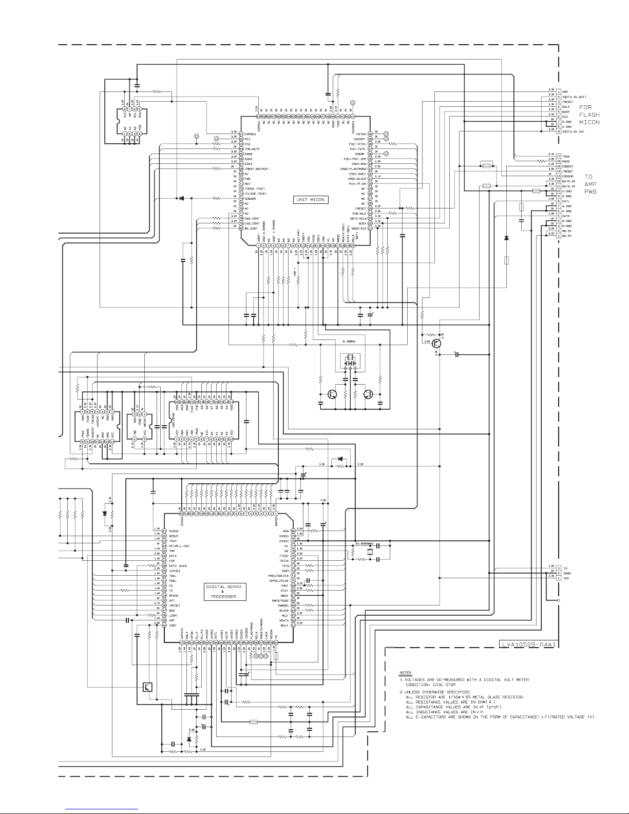
RASCNT
NI
R850
SN74LV08APW-X
IC682
R849
NI
5.6k1k5.6k
R803
R812
CN653
C201
R299
NI
47k
NI
IC201
PC2
DRMUTE
EQX5
EQX2
EQX4
REST
CDDOOR
0.1/16
R652
27
R679
C656
C657
680p
/DWE
SN74AHC1G32DC-X
IC681
R651
0
0.1/16
C658
WECNT
R851
NI
0.1/16
C655
C654
0.1/16
47k
R653
22k
NI
75k
R654
R683
NI
Q654
C681
0.01/25
R661
15k
CASCNT
/DCAS
/DRAS
NI
D654
R816
TBAL
FBAL
FE
TE
RFENV
OFT
/RFDET
BDO
GCTL
ARF
NI
C660
RB521S-30-X
D251
RASCNT
CASCNT
WECNT
NI
C262
D3
D0
R659
47k
R251
D2
D1
270
2701000p
R847C661
R848
AD3
R656
0.022
C659
NI
D655
TP19
R289
R262
R263
R264
AD9
IC671
GLT4160L04P50TC
270
270
R846
R845
AD2
AD1
AD0
100k
820
R657
0.082
C662
C663
0.1/16
240
R658
15k
TP18
R260
R261
R266
AD8
AD10
2701k270
R844
C664
1k
1k
1k
1k
1k
1k
1k
47k
R268
NI
NI
C261
C256
10k
R253
AD7
AD6
AD5
AD4AD3
0.1/16
C653
AD2
AD1
AD0
270
270
270
270
270
270
270
270
270
270
270
R843
R842
R841
R840
R839
R838
R837
R836
R835
R834
R833
R832
D3
D2
AD10
0.1/16
C667
/DCAS
R664
10/25
C673
R662
K651
QQR0621-001Z
D1
/DWE
/DRAS
TP13
TP11
TP12
100
AD9
AD4
AD5
AD6
AD7
AD8
IC651
MN6627934CH
C665
0.1/16
C666
100/6.3
47/6.3
47k
R293
270
C690
R831
0.1/16
D0
R665 R666
47k
47k
R294
R295
10k
R681
R235
NI
C691
NI
K654
NQR0007-002X
680 560
C668
NI
C671
NI
R667
680
IC251
MN101C61GNJ
NI
R254
R236
R830
R668
560
47k
C652
0.1/16
R675
R674
C674
0.1/16
R673
R672
R671
R669
TXD0
RXD0
100p
C259
2.2k
C232 C231
R234
39p 39p
0.001
C234
Q232 Q231
2SC2814/4-5/-X 2SC2814/4-5/-X
0
D652
R678
C651
100/6.3
100/6.3
C678
C677
0.1/16
MON
R676
1k
TXTCK
TXTD
1k
DQSY
1k
/RST_DSP
1k
STAT
1k
33k
1k
BLKCK
MLD
MDATA
MCLK
FLAG
C669
0.0018
C672
0.0018
1k
R278
1k
1k
R255
R256
MCLK
MDATA
STAT
C251 C252
0.1/16 47/6.3
X251
QAX0684-001Z
8.2k
R232
NI
0
NAX0476-001X
TX
OUTR
OUTL
TP17
TP16
TP15
TXTCK
TXTD
1k
R267
TP14
/RST_DSP
MON
FLAG
DQSY
BLKCK
R274
1k
1k
R258
10k
10k
10k
R296
R259
R265
2.2k
R233
8.2k
C233
0.001
R231
X651
C675
10p
1M
R655
R682
C676
10p
390
MLD
C253
0.1/16
1.2k
R297
10k
R298
Q291
2SB1424/QR/-W
K253
NI
K251
NQR0007-002X
22/6.3
C291
OUTL
OUTR
TX
D252
RB521S-30-X
K254
NQR0007-002X
TXD0
RXD0
R271
K252
NQR0007-002X
K250
NI
C255
NI
NI
1k
CN651
QGF1036F1-17
CN652
NI
QUB220-******
2-18
Page 52

Cassette mechanism section (common)
0 022
BA3126N
IC31
R301
220
R116R216
C301
VGH0425-544
QGF1201F3-06
CN31
100/10
C391
680P
R207
R107
12K
12K
B406
QUY360-125F
Q102
C113
C213
R210
R110
4.7K
0.0022
0.0022
4.7K
C111
0.0012
C211
0.0012
R213
R113
4.7K
4.7K
DTC114TKA-X
DTC114TKA-X
2.7K
R114
C112
0.068
R112
R111
R211
R212
2.2K
C212
0.068
R214
2.7K
Q202
2.2K
33K
33K
100K
560P
4.7/25
22/16
10/16
10/16
3.3K
560P
C207
22/16
C109
C305
C304
C107
3.3K
C306
47/16
C108
4.7/25
220/6.3
4.7/25
0.039
C302
C303
C208
4.7/25
39K
R303
C209
R108
5.6K
R104
1.2K
R304
100
IC32
AN7317
R204
R208
R109
1.2K
1.2K
5.6K
R209
1.2K
22
R101
2.4K2.4K
R102
1.8K
R202
1.8K
Q201
R105
R106
C106
C206
R206
DTC114TKA-X
100K
0.0022 0.0022
C205 C105
R205
0.033
C104
820P
C103
220/6.3
C101
1K1K
C110
0.0068
C210
0.0068
820P
C201
220P
C102
220P
C202
Q101
DTC114TKA-X
C204
0.033
C203
220/6.3
22
R201
R103
R203
R327
470K
NI
C325
Q311
TW2
C319
2SC2412K/RS/-X
2SC2412K/RS/-X
12K
820P
Q306
Q307
QVP0008-503Z
VR31
QVP0008-503Z
VR32
R319
1.5K
C318
L303
QQL01BK-100Z
L301
QQR0620-001
C311
0.0068
100/10
1.5
C314C315
C351
10/16
C313
R351
R352
68k
1.5
9.1K
0.01
C316
12K
R332
0.01
3.3
R313
56
R311
R310
2SC2001/LK/-T
C309
22K
R316
Q303
2SC2001/K/-T
B199
0
56
Q305
R317
10
C121
R121
1K
330P
C221
R221
1K
330P
R325
NI
NI
C326
Q310
NI
NI
NI
NI
C324
R326
C322
NI
R334
0.0015
Q309
2SC2412K/RS/-X
R322
1.5K
Q308
2SC2412K/RS/-X
C321
0.01
R333
0.0056
2SC2001/LK/-T
MA152WA-X
2SC2001/K/-T
Q304
2SC2412K/RS/-X
Q302
C308
D301
R315
Q323
C310
0.0056
10
22K
R314
R306
2.2K
2-19
Page 53
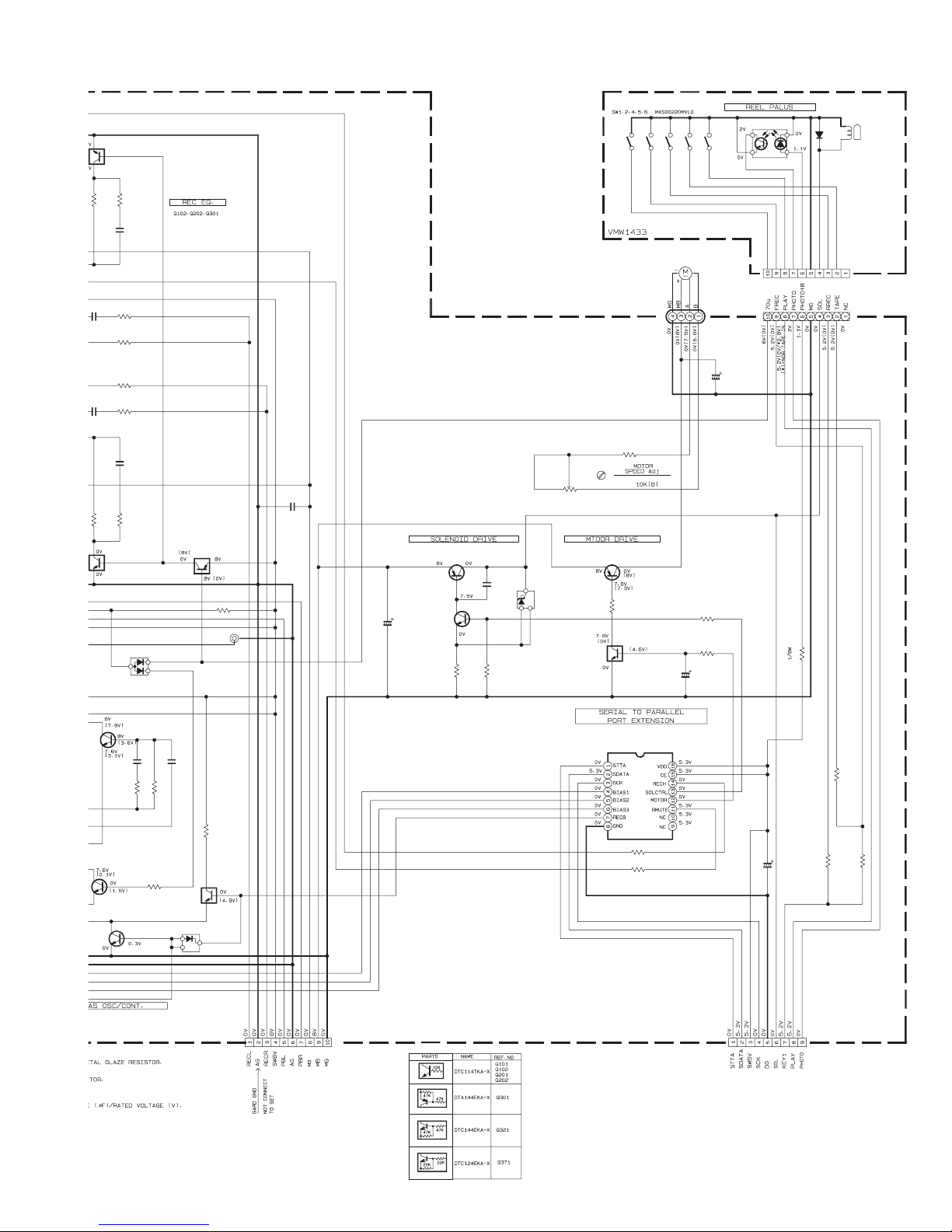
C
C
R213
R113
.
0
4.7K
111
0012
211
012
4.7K
Q102
DTC114TKA-X
2.7K
R114
C112
R112
R111
R211
R212
2.2K
C212
R214
2.7K
Q202
DTC114TKA-X
MA152WA-X
0.068
0.068
D301
IC1
SG-10SF3
VGP2401-00A
D1
390
R340
1SR139-100T
EMV7159-010
CN1
CN32
QGB2011M1-10
SW1
SW2
C371
SW6
QSEC001-E03
MSI-5U2LWA
R338
3.9K
R337
3.3K
4.7/25
C374
100/10
SW4
SW5
2.2K
33K
33K
VR37
QVP0008-103Z
Q371
Q301
DTA144EKA-X
R305
2.2K
TW1
C307
0.01
2SB562/C/-T
C375
100/10
2SC2412K/RS/-X
Q375
Q376
R375
C376
0.01
D375
HZM5.1NB2-X
150
R376
4.7K
QUM024-06A2Z3
R371
2SA952/LK/-T
R372
1K
Q372
DTC124EKA-X
FW31
12K
T
2SC2001/LK/-T
Q302
2SC2001/K/-T
Q304
2SC2412K/RS/-X
C308
R315
Q323
10
0.0056
R314
R306
2.2K
IC33
BU4094BCF-X
C310
0.022
22K
R335
1.5K
Q321
D309
MA704A-X
CN34
QGF1201F3-10
DTC144EKA-X
R339
2.2K
R336
47/16
4.7K
CN33
QGF1205F1-09
C331
R342
R341
20K
12K
18K
R343
2-20
Page 54
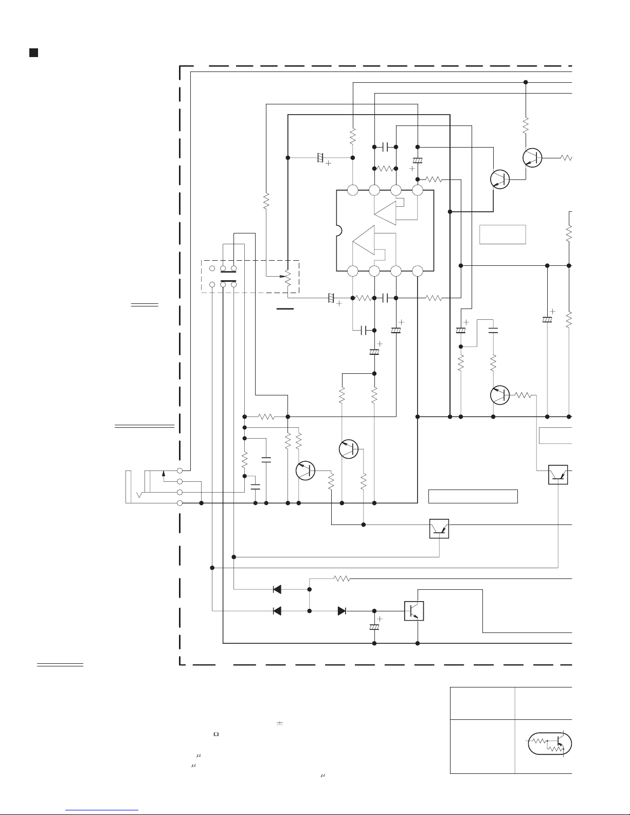
Mixing mic section (for J,C)
2
S
A
9
VR731
VR731
QVQ0287-B24
VOLUME
(WITH SW)
GUITAR
654
MIC
100
R7368
100
C7356
47/25
22K
R7359
IC751
NJM4565M-WE
789
2
31
20K
1/4W
C7354
1/50
C7357
R7361
68P
R7362
220K
4.6V
8.9V
8765
VCC
4.6V
4.6V
R7353
39K
C7352
330P
+
-
C7369
NI
4.6V
-
+
4.6V
C7351
C7355
4.6V
4321
0.1/50
GND
1/50
R7360
27K
0V
R7352
82K
C7358
0V
MIC/GUITAR
10/50
Q7354
2SC3928A/RS/-X
AMP
C7359
9.0V
0V
0.068
0V0V
Q7357
2SC3928A/R
0V
47/25C7360
R73
100
R7369
68KR7370
NOTES
MIC/GUITAR JACK
J7351
QNS0148-001
C7353
0.33/50
0.7V
R7357
C7370
R7355
(0V)
10K
56K
9.2V(0V)
0.3V
0.1/50
Q7353
UN2112-X
0V
0V
MIC/GUITAR GAIN CTL
Q7360
DTC115EKA-X
4.7K
15K
R7356
0V
0.7V
(0V)
R7358
R7388
10K
D7359
1SS133-T2
2SC3928A/RS/-X
Q7352
0V
10K
R7351
180K
33K
0V
NI
R7354
R7386
0V
Q7351
4
2
1
3
R7387
D7357
D7358
1K
C7381
C7382
NI
2SC3928A/RS/-X
1SS133-T2
1SS133-T2
9.2V
0V(9.2V)
1.8K
R7366
Q7356
2SC3928A/RS/-X
0V
0V
R7365
1.2K
0V(0.7V)
R7367
10K
0V(9.2V)
9.2V(0V)
MIC/GUIT
Q7355
UN211
EQ SW
1. VOLTAGES ARE DC-MEASURED WITH A DIGITAL VOLT METER
OR OSCILLOSCOPE WITHOUT INPUT SIGNAL.
CONDITION --- CD STOP AT AC SUPPLY
() IS GUITAR POSITION AND NORMAL IS MIC POSITION
2. UNLESS OTHERWISE SPECIFIED RESISTORS ARE 1/16W
ALL RESISTANCE VALUES ARE IN OHM( ).
ALL CAPACITORS ARE CERAMIC CAPACITOR
ALL CAPACITANCE VALUES ARE IN
ALL INDUCTANCE VALUES ARE IN
F(P=pF).
H(m=mH).
ALL E.CAPACITORS ARE SHOWN IN THE FORM
2-21
5% MG RESISTOR
OR MYLAR CAPACITOR.
OF CAPACITANCE ( F )/RATED VOLTAGE (V).
PARTS
NAME
CONSTRUCTION
UN2112-X
22K
22K
Page 55

Q
100
7357
SC3928A/RS/-X
R7373
0V
RS/-X
7
.2V)
100K
47/25C7360
MIC/GUITAR
EQ SW
Q7355
UN2112-X
R7369
68KR7370
9.2V
68K
C7362
R7375
D7352
3.3/50
K7351
QQR0621-001Z
2.2K
1SS133-T2
D7353
C7363
2.2K
R7376
1SS133-T2
3.3/50
IC752
NJM4565M-WE
DETECTOR
BUFFER AMP
R7379
56K
R7380
R7382
Q7358
2SC3928A/RS/-X
0V
39K
0V
R7371
10K
0V
4321
GND
47K
+
-
4.6V
4.6V
1/50
C7365
R7381
10K
0.7V
4.6V
-
+
4.6V
C7361
220P
R7372
10K
4.6V
D7360
8765
8.9V
C7366
Vcc
4.6V
47/25
1/4W
R7383
100
C7367
1/50
MIC MUTING
DRIVE
Q7359
2SA1530A/QR/-X
9.2V
8.6V
R7384
47K
9.2V
R7385
47K
.2V(0V)
D7354
470K
R7374
UN2112-X
22K
22K
C7368
DTC115EK
100K
100K
1/50
R7377
1SS133-T2
2.2K
D7355
2.2K
R7378
1SS133-T2
1SS133-T2
QGA2001F1-04
0.5V
4
JACK
0V
3
AG
CN751
TO UCOM PWB (FW403)
2
SIG
D7351
1SS133-T2
0V
9.2V
1
SW9V
2-22
Page 56

Mixing mic section (for B,E,EN,EV)
2
A
9
MIC
GUITAR
789
VR731
VR731
QVQ0287-B24
VOLUME
(WITH SW)
654
R7359
22K
2
20K
C7356
47/25
IC751
NJM4565M-WE
31
C7354
1/4W
R7361
8765
VCC
4.6V
R7353
1/50
C7352
330P
8.9V
39K
100
4.6V
4.6V
C7357
68P
R7362
220K
+
-
C7369
330P
C7351
-
+
4.6V
4.6V
C7355
4.6V
4321
0.1/50
GND
1/50
R7360
27K
0V
R7352
82K
C7358
0V
MIC/GUITAR
10/50
9.0V
0V0V
0V
Q7354
2SC3928A/RS/-X
AMP
0.068
C7359
100
R7368
Q7357
2SC3928A/RS
0V
47/25C7360
R73
100
R7369
68KR7370
NOTES
MIC/GUITAR JACK
J7351
QNS0148-001
C7353
0.33/50
0.7V
R7357
C7370
R7355
(0V)
10K
56K
9.2V(0V)
0.3V
0.1/50
Q7353
UN2112-X
0V
0V
Q7360
DTC115EKA-X
MIC/GUITAR GAIN CTL
4.7K
15K
0V
0.7V
(0V)
R7358
R7388
D7359
1SS133-T2
R7356
2SC3928A/RS/-X
Q7352
0V
10K
10K
R7351
180K
33K
4
2
1
3
R7387
1K
C7381
D7357
D7358
C7382
220P
2SC3928A/RS/-X
1SS133-T2
1SS133-T2
0.001
R7386
0V
R7354
0V
Q7351
9.2V
0V(9.2V)
1.8K
R7366
Q7356
2SC3928A/RS/-X
0V
0V
R7365
1.2K
0V(0.7V)
R7367
10K
0V(9.2V)
9.2V(0V)
MIC/GUIT
Q7355
UN211
EQ SW
1. VOLTAGES ARE DC-MEASURED WITH A DIGITAL VOLT METER
OR OSCILLOSCOPE WITHOUT INPUT SIGNAL.
CONDITION --- CD STOP AT AC SUPPLY
() IS GUITAR POSITION AND NORMAL IS MIC POSITION
2. UNLESS OTHERWISE SPECIFIED RESISTORS ARE 1/16W
ALL RESISTANCE VALUES ARE IN OHM( ).
ALL CAPACITORS ARE CERAMIC CAPACITOR
ALL CAPACITANCE VALUES ARE IN
ALL INDUCTANCE VALUES ARE IN
F(P=pF).
H(m=mH).
ALL E.CAPACITORS ARE SHOWN IN THE FORM
2-23
5% MG RESISTOR
OR MYLAR CAPACITOR.
OF CAPACITANCE ( F )/RATED VOLTAGE (V).
PARTS
NAME
CONSTRUCTION
UN2112-X
22K
22K
Page 57
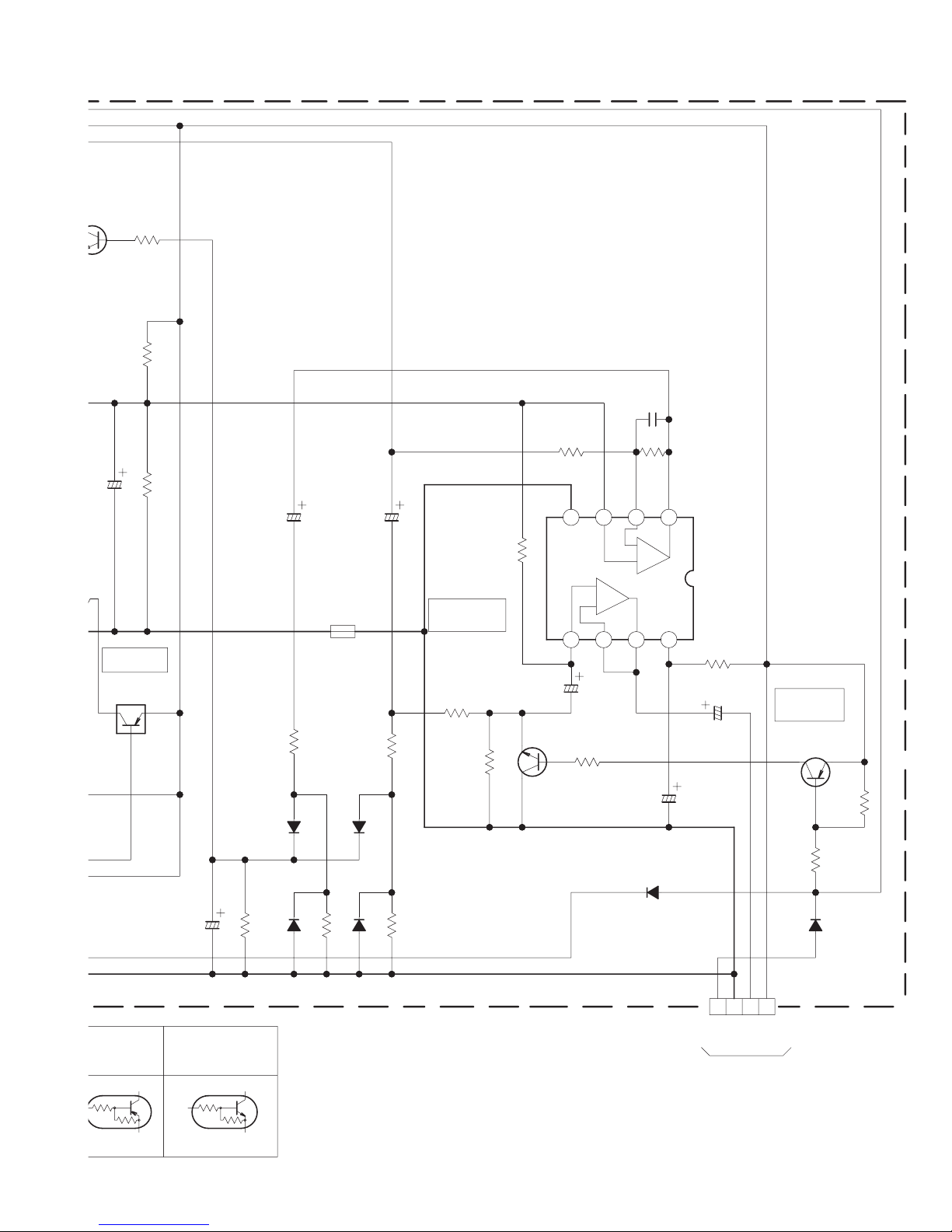
100
7357
SC3928A/RS/-X
0V
RS/-X
47/25C7360
7
MIC/GUITAR
EQ SW
Q7355
UN2112-X
.2V)
.2V(0V)
R7373
100K
R7369
68KR7370
9.2V
68K
C7362
R7375
D7352
3.3/50
K7351
QQR0621-001Z
2.2K
1SS133-T2
D7353
C7363
2.2K
R7376
1SS133-T2
3.3/50
IC752
NJM4565M-WE
DETECTOR
BUFFER AMP
R7379
56K
R7380
R7382
Q7358
2SC3928A/RS/-X
0V
39K
0V
C7361
4.6V
4.6V
-
+
4.6V
220P
R7372
10K
4.6V
D7360
8765
8.9V
C7366
Vcc
4.6V
47/25
1/4W
R7383
100
C7367
1/50
R7371
10K
0V
4321
GND
47K
+
-
4.6V
1/50
C7365
R7381 2SA1530A/QR/-X
10K
0.7V
MIC MUTING
DRIVE
Q7359
9.2V
8.6V
R7384
47K
9.2V
R7385
47K
470K
R7374
UN2112-X
22K
22K
C7368
DTC115EK
100K
100K
1/50
D7354
R7377
1SS133-T2
2.2K
D7355
R7378
1SS133-T2
2.2K
1SS133-T2
QGA2001F1-04
0V
CN751
0.5V
3
4
AG
JACK
TO UCOM PWB (FW403)
2
SIG
D7351
1SS133-T2
0V
9.2V
1
SW9V
2-24
Page 58

Tuner section (for J,C)
R13
123456789
0
0.8
0
2.5
13 14
2.0
2.5
0
0.7
0
0.8
0
000
1.0
0
15 16 17NC18 19 20 21NC22 23 24
2.3
0.7
2.3
0.7
000.7
0
B1
NI
L12
QQR0756-001
IC1
IC2
IC1
IC2
PIN NO
FM NO SIGNAL
FM 60dB STEREO
AM NO SIGNAL
FM NO SIGNAL
PIN NO
FM NO SIGNAL
FM 60dB STEREO
AM NO SIGNAL
FM NO SIGNAL
TP1
QNZ0104-001
TO ROD.ANT.
3.1
3.0
3.2
0.3
1.4
1.4
1.0
2.5
BP1
QQR0768-001Z
123
QQL231K-4R7Y
100
0
0.6
0.102.7
3.0
3.0
3.2
0
1/16W
D
Q2
S
L2
10 11 12
2.4
2.3
0
3.0
3.0
3.2
R5
150
C10
0.01
C4
20P
2SK360/E/-W
(FM RF)
QQR1721-001
1.2
1.2
1.2
1.2
1.2
1.2
0
0
3.0
3.0
3.0
3.0
3.2
3.2
BAR ANT
1
2
4
L3
3
QQR0745-001
3
1
SVC344-T
D8
R20
2
C21
0.047
22K
NI
C18
3P
C12
8.2P
C5
C6
D3
SVC203SPA-JV-T
1
3
0.01
2
L11
QQR1719-001
3
R10
100K
1
42
C8
220P
TC2
QAT3725-200Z
3.1
2.6
3.0
2.5
3.2
2.6
0.3
0.3
5.1
0.8
0
0.7
0.8
5.1
5.0
0.7
3.1
3.0
3.2
2.3 2.1
2.9
2.9
3.1
0.7
0
0
0
3.0
3.0
3.2
1.7 2.4
L9
R6
R8
100K
3.8V
0V
G
1/16W
2
13
0V
4
C2
220P
NIC1
QNZ0104-001
QNZ0104-001
1SS133-T2
D5
FM GND
TP2
TP3
1SS133-T2
D6
C63
0.001
C62
12P
100K
R1
C13
C64
12P
D2
SVC203SPA-JV-T
2
47K
R2
4.7K
1/16W
0.022
QAX0402-001
X1
3
1
C7
C9
R4
R9
47K
C77
0.001
C61
C60
22 21 20 19 18 17 16 15 14 13 12
QQL231K-221Y
L7
XTXTNC CLOCKCE STOP
D1
SVC203SPA-JV-T
1
2
3
5.6P
C3
C11 3P
NI
C56
R3
27
L1
L1
QQR0772-001
QQR0772-001
0.01
3
6
12P
1
(FM OSC)
0.01
R54
2.2K
R56
100/16
GND FM
R42
47K
C69
0.0022
R55
2.2K
R52
PD
LPF
LPF
OUT
IN
PLL
DI
1K
1KR61
R59
C16
0.01
3.3K
C70
2.2/50
10K
Vcc
ST VCO
R60
1K
C71
10/50
C65
AM IF IF
IN IN
FM
AM/
FM
22
R47
1/16W
R63
47K
1/16W
IC2
LC72136N
0.001
1/16W
CONT
R57
1K
2.2K
0.001C37
R44
IN
NCD01
NC
1110987654321
2-25
L10
QQL231K-4R7Y
Page 59

TC2
QAT3725-200Z
1
SVC344-T
D8
R20
NOTES
1.VOLTAGES OF THE TABLE ARE DC-
(MW OSC)
L4
QQR0723-001
C22
430P
3
R13
100K
2
C21
0.047
1/16W
12P
C23
123
46
1/16W
R18
1K
2.ALL RESISTORS ARE 1/4W 5% CARBON RESISTOR.
3.ALL RESISTANCE VALUES ARE IN OHM ( ).
4.ALL CAPACITANCE VALUES ARE IN F (P=pF).
5.ALL E.CAPACITORS ARE SHOWN IN THE FORM OF CAPACITANCE ( F )/RATED VOLTAGE (V).
6.ALL INDUCTANCE VALUES ARE IN
MEASUREDWITH A DIGITAL VOLT METER.
H(m=mH).
22K
K1
QQR0779-001Z
56
R37
R25
2SC2668/O/-T
1K
C31
0.001
1/16W
R48
1K
24 23 22 21 20 19 18 17 16 15 14 13
AM
RF
RF
VCC
1
IN
FM RF/IF/DET/MPX AM RF/IF/DET
FM
AM
RF
LOW
IN
CUT
FM
OSC
MIX
OUT
FM
RF
IC1
OUT
TA2104ANG
RF
GND1
0.01
C32
2.9V
OSC
AM
OUT
OSC OUT
AM
IF
VCC2
IN
330P
Q1
3.0V2.2V
R24
1/16W
ST
IF
LED
REQ
FM
IF
GND2
IN
0.1/50
1/50
C41
QUAD
C44
C45
R32
3.3K
C43
4.7/50
MPX
LPF
LPF
IN
1
2
R-CH
L-CH
OUTOUT
121110987654321
0.1/50
C51
680
DET
AGC
LC72136N
C36
C42
0.1
T1 QQR1722-001
R63
47K
1/16W
(FM IF)
R30
C35
18K
0.1/50
1
2
CF1
1/16W
470
R40
3
QAX0403-001
1/16W
R33
46
27P
123
C53
T2
QAX0540-001
567321
1K
10 9 8 4
(AM IF)
22
1/16W
R81
1/16W
22K
R83
3.0V
1/16W
R84
3.3K
2SA1530A/QR/-X
C81
2.4V
0.01
1/16W
R82
0.4V
Q3
3.3K
4.7/50
CF3
QAX0538-002Z
R38
1/16W
C38
0.01
100
C40
0.01
ZD1
MTZJ3.0B-T2
100KR31
1K
C33
R64
100/16
120
R39
NIC67
C66
150P
C47
0.012
22K
R35
C48
0.012
C49
0.1/50
22K
R36
C50
0.1/50
0V
ANTGND
1
0V
GND
2
0V
RCH
3
0V
LCH
D12
1A3G-T1
4
5.8V
6V
5
5.0V
MPX
6
0.3V
DATA
7
0.2V
CLOCK
8
0V
9
PERIOD
(CN403)
TO uCOM PWB
CN1
QGF1205C2-09
LVA10662-A1
2-26
Page 60

Tuner section (for B,E,EN,EV)
TP1
TP2
L12
QQR0756-001
D5
D6
C56
0.001
L2
QQR0769-001
C52
R7
0.001
100K
6.8P
C3
Q2
QQR0771--001
C6
0.01
47K
R1
R2
100K
D2D1
R9
C13
1K
0.022
R3
4.7
12P
C9
C7
20P
L1
QQR0772-001
R54
2.2K
C16
0.01
C77
0.001
Q4
Q5
R15
2.2K
R36
2.2K
TC2TC3
R14
10K
62P
C24
C64
C62
12P
X1
12P
0.001
C63
0.001
C60
L7
QAX0402-001
100/16
C61
220
LC72136N
R42
47K
C70
2.2/50
4.7K
C71
3.3/50
0.001
C65
R41
2.2K
2.2K
R44
R40
2.2K
0.001
C37
R57
1K
1K
1K
R45
R51
R56
3.3K
0.0022
C69
R55
2.2K
R52
IC3
1K
1K
1K
R61
R59
R60
2-27
Page 61

C22
QFP31HJ-431Z
L4
QQR0723-001
TC2TC3
62P
C24
R21
10k
R20
1K
R12
4.7K
0.01
C32
0.047
C25
0.1/50
C21
R16
4.7K
R17
C27
C28
R13
Q6
C26
180P
100K
100K
100P
15P
12P
C23
L6
QQR0774-001
0.001
C31
R18
1K
Q3
Q14
R19
2.2K
56
R37
R48
1K
R47
470
IC2
TA2008AN
680P
C51
R31
C40
12K
1/50
47K
C41
1/50
C44
10/50
0.47/50
C45
CF4
QAX0778-001
C47
0.012
R46
10K
QAX0403-001
R33
CF1
100
R28
5.1K
C36
T2
4.7/50
C42
QQR0719-001
0.047
CF3
QAX0404-001Z
C35
R64
1K
R30
100K
0.01
C66
150P
C48
0.012
C33
100/16
D12
1A3G-T1
C50
18K
R35
C49
18K
R34
0.1/50
0.1/50
CN1
QGF1205C1-09
GND
Rch
Lch
6V
MPX
DATA
CLOCK
PERIOD
2-28
Page 62

Printed circuit boards
Main board (for J,C)
(Power amplifier board)
D3493
R3508
IC390
R3316
R3311
R3310
R3309
R3308
R3313
Q3305
C3302
R3305
R3507
R3301
R3314
Q3306
R3302
R6303
C3303
Q3301
D3301
R3303
C6106
C6107
Q3304
R3304
R3315
Q3191
Q3193
D3302
C3301
R3312
Q3303
R3307
Q3492
R3191
R3306
D3901
C6206
R6305
R6204
C6105
C6303
Lead free solder used in the board (material : Sn-Ag-Cu, melting point : 219 Centigrade)
R6307
R6322
Q6307
C6312
R6314
R6306
C6311
C6308
R6308
C6323
R6309
D6304
R6315
R6316
R6317
C3491
R6321
Q6308
R6320
R6319
C3493
C6314
R3499
R3491
C6319
C6318
R3500
R6318
R3506
D3492
R3501
R3503
R3494
R3505
C6317
R3492
R3493
R3496
FW601
Q3496
Q3493
Q3495
C6316
Q3302
R6103
C6104
R6104
Q3192
C6304
R3197
C6204
Q3196
R3193
C6207
R6203
C3902
R3192
R6304
C6205
Q6302
Q3197
Q3194
R6302
C3901
C3191
C3192
C6305
R6301
C3193
R3200
D3192
Q6301
C6302
IC601
C3194
D3193
C6306
R3199
R3198
L3191
R3194
Q6201
R6205
R6202
R3201
C6301
C6203
C6201
R3202
R3195
D3191
D3194
C6202
R6201
D3195
R6101
C6103
C6102
R3204
R3196
C6101
R3203
Q3195
Q3198
D3196
R6102
CN603
R3901
Q6101
R6105
C6315
R6312
Q6303
C6313
C6321
IC301
R6313
R6310
D6302
R6325
C6307
C6310
Q6305
R6311
C6324
C6320
Q6306
Q6304
R7341
C6309
R3498
R3504
C3492
R3502
Q3491
FW602
Q3494
R3497
R3495
D3491
CN192
F1902
WC2
C1903
D1901
2-29
(Power supply board)
CN195
WC1
C1901
R1901
F1903
F1904
CN194
F1901
S1901
C1904
J1901
C1902
D1902
J1902
Page 63

FW603
BS2
(Equalizer amplifier board)
(BAttery spring board)
BS1
R7330
C7316
C7317
R63
C67
C5308
R7301
R5107
R5106
CN604
L3
Q7303
IC701
Q2
R7310
C7309
IC702
R7313
D7306
D7305
R4
R6
R8102
R2
R8108
R8107
C8103
R8105
R8204
R7303
IC801
R8103
C8102
C8101
R8109
C8104
C2
C1
R8
C10
L12
D6
L9
D5
D7301
D7302
R7323
R7325
R7324
R7326
R7328
R7331
R7329
R7327
C66
CN1
B2
D12
R84
R7332
D7303
C7318
D7304
C7313
IC703
C7314
R7318
C7312
R57
B3
R60
IC2
R42
R59
R61
C62
C64
C63
C45
L10
C44
R39
C43
R31
R64
C50
C49
R32
C51
C33
C40
R36
ZD1
C48
R35
R83
C81
C47
B4
R7338
C7319
R7333
IC704
R7334
R7335
R7337
R7336
C7311
Q7302
R7342
R7321
R7322
C37
R44
C65
C61
C60
X1
R25
L7
R48
R24
C41
Q1
CF3
R38
C36
CF1
R40
C38
R33
R82
R81
Q3
C7322
C7320
C7323
R7339
C7324
R7317
C7307
C7321
R7344
Q7301
R7320
C70
R55
C69
R56
R47
R52
C71
C3
C31
C11
C6
C42
IC1
T2
C53
T1
R7305
C7302
C7306
C7310
C7
C7305
D7307
R7343
C7301
R7311
R7314
C7308
L4
R13
C21
TC2
K1
C13
R9
C9
D2
C77
R10
D3
C5
C56
C4
TP3
R7308
C7303
R7307
R7309
R7315
R7316
R7319
R7312
R18
C22
C23
D8
R20
R54
R37
D1
R1
L2
C16
R3
C32
L1
R30
C8
C35
L11
C12
BP1
Q8101
R8201
C18
R8209
C8204
C8301
B1
R8208
R5
R8111
C8202
TP2
R5206
R8207
D8301
R8104
C8201
R8202
TP1
R5207
R8302
C8303
R8327
C8203
R8321
R8203
C8203
R8205
R8301
R8101
(Tuner board)
R8211
Q8201
C8322
2-30
Page 64

Main board (except J,C)
(Power amplifier board)
D3493
R3508
IC390
R3507
D3901
Lead free solder used in the board (material : Sn-Ag-Cu, melting point : 219 Centigrade)
C3902
CN603
C3901
R3901
R6322
R6307
Q6308
R3316
R3311
R3310
R3309
R3308
R3313
Q3305
R3314
C3302
R3305
R3301
Q3306
R3302
R6303
C3303
Q3301
D3301
R3303
R3304
C6106
C6107
Q3304
R3315
Q3191
Q3193
R3312
Q3303
R3307
Q3492
R3191
D3302
C3301
R3306
C6105
C6303
C6206
R6305
R6204
R6103
C6104
R6104
Q3192
C6304
R3197
C6204
Q3196
R3193
C6207
R6203
R3192
R6304
Q6302
C6205
Q3197
Q3194
R6302
C3191
C3192
C6305
C3193
R3200
R6301
D3192
Q6301
C6302
IC601
C3194
D3193
C6306
R3199
R3198
L3191
R3194
Q6201
R6202
C6208
R6205
C6203
C6201
R3201
C6301
R3202
R3195
D3191
D3194
C6202
R6201
C6108
D3195
R6101
C6103
C6102
R3204
R3196
Q3198
C6101
R3203
Q3195
D3196
R6102
Q6101
R6105
C6315
R6312
Q6303
C6313
C6321
IC301
R6313
R6310
D6302
R6325
C6307
C6310
Q6305
R6311
C6324
C6320
Q6304
Q6306
R7341
C6309
R6306
Q6307
C6312
R6314
C6311
C6308
R6308
C6323
R6309
D6304
R6315
R6316
R6317
C3491
R6321
C3493
R6320
R6319
C6314
R3499
R3491
C6319
C6318
R3500
R6318
R3506
D3492
R3501
R3503
R3494
R3505
C6317
R3492
R3493
R3496
Q3496
Q3493
C6316
FW601
Q3495
R3495
Q3302
R3498
R3504
C3492
R3502
Q3491
FW602
Q3494
R3497
D3491
CN192
CN193
CN191
Z1902
(Power supply board)
Z1911 Z1901
Z1922
D1901
CN195
Z1933
R1901
CN194
WC1
C1904
C1901
C1902
Z1903
Z1904Z1944
WC2
C1903
LF191
J1901
D1902
J1902
2-31
Page 65
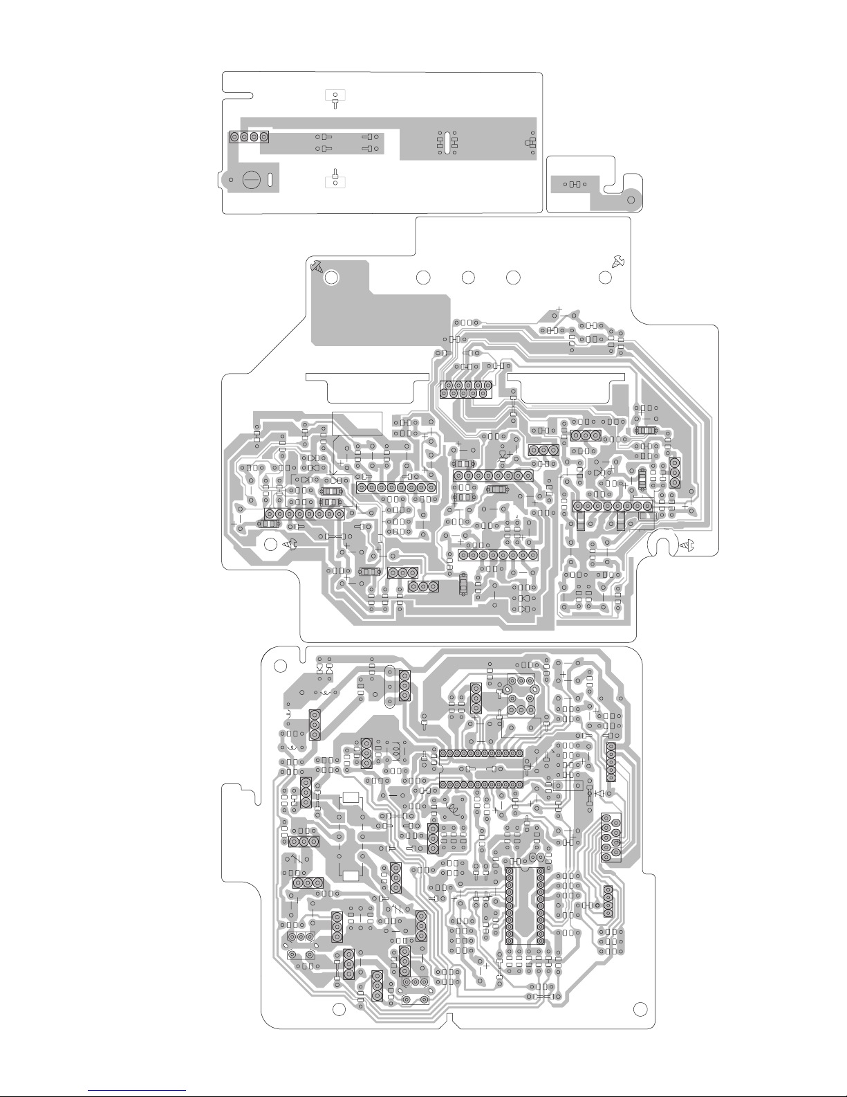
FW603
BS2
(Equalizer amplifier board)
(BAttery spring board)
BS1
R7330
C7316
C7317
R7329
R7327
R7331
R16
C5308
R7301
R5106
CN604
Q7303
R7310
C7309
IC702
R7313
D7306
D7305
C51
R8102
R35
C64
R51
C47
C49
C48
C35
R64
R31
C43
IC3
R8108
R8107
C8103
R8105
R7303
R8103
C8102 C8202
C8101
R8109
C8104
CF4
C45
C62
R41
R45
R8204
C8205
D7301
D7302
R7325
R7323
R7326
R7332
D7303
R7328
D7304
IC703
R7318
D6
TP1
C75
L13
R71
R66
Q4
C17
R67
R15
Q5
C24
TC3
D10
C25
L6
R7324
C7318
C7313
C7314
C7312
D5
Q16
R2
C77
R14
L3
R21
C28
C26
Q6
Q14
R7338
C7319
R7333
IC704
R7334
R7335
R7337
R7336
C7311
Q7302
R7342
R7321
R7322
C56
TP2
R72
D2
C9
R4
R3
L1
R9
C13
R1
R23
C27
TC2
R17
C21
R13
C76
C23
R73
Q17
R18
C7322
C7320
C7323
R7339
C7324
R7317
C7307
C7321
R7344
Q7301
R7320
BP1
C32
C7
C16
C52
D1
R37
Q2
R54
D8
R20
R52
R56
C69
R55
Q3
C22
R36
R12
L4
R7305
C7302
C7306
C7310
C31
C7305
D7307
IC701
R7343
C7301
R7311
R7314
C7308
R46
R30
T2
CF3
C33
C44
R48
C41
L7
C63
L5
C60
X1
C61
C65
C70
R40
R44
C37
R57
R7308
C7303
R7307
R7309
R7315
R7316
R7319
R7312
CF1
R28
R33
C36
C42
IC2
L2
R47
C6
C3
R7
C78
C74
C71
R5107
R61
R59
R42
R60
Q8101
IC801
R8201
C50
C68
C66
C67
R5207
R5206
R8302
C8203
C8105
R8101
R8327
C8304
C8203
R8301
R8205
C8303
R8203
R8211
Q8201
C8322
R8321
R8208
R8111
R8207
C8301
D8301
R8104
C8201
R8202
R8209
C8204
R34
R38
R39
C40
CN2
D12
(Tuner board)
CN1
CN3
2-32
Page 66

Micon board (for J,C)
(Display control board)
Lead free solder used in the board (material : Sn-Ag-Cu, melting point : 219 Centigrade)
C6157
L6353
R6153
C9126
R9226
L6351
Q6150
R9230
J6301
R9131
C9134
R6154
Q6350
D6502
R9126
R6354
C6352
R5306
R9129
R9130
Q6351
D6303
R9012
R9134
R9135
C9011
R9011
D9126
R9237
C9137
R6160
Q6151
C9012
IC902
R9013
C6153
D6503
R8370
R5307
Q9005
R6150
L6352
C6257
C6155
R6152
C6351
C6150
R8356
R8355
R8353
Q8353 Q8354
R8367
R8362
D9014
R9016 R9017
Q9006
R9136
R9238
CN901
R6157
R8354
D9011
R9218
R9015
C9138
R6151
R6158
Q9004
R6353
R6161
R9014
C9136
R8360
C8351
R9139
IC831
R8361
R9018
C6151
Q6251
C8354
R9133
R9142
R6251
R6252
C6255
R8364
CN407
C8362
R8359
C4142
C8363
R4143
R9221
R6250
C6251
R6401
R9137
R9239
C6252
R6257
IC603
R6260
C6350
R5305
CN907
R9138
B4007
C6152
D6501
R6258
Q6401
R5302
R6350
R6335
C6250
R9145
R5308
R6261
R9222
C9142
R9240
R9148
C5303
C5305
R9223
R9146
R9149
C9145
C5302
C5306
Q3672
C5103
R9140
R9147
C5309
C5203
C9133
C9247
DI901
C9146
C9147
FW403
R5301
R3671
C9148
R3672
Q3671
R4351R4352
R9172
C9149
R4353
R9173
C5304
R9224
C5307
R5502
R9174
R5303
R5304
R6155
C6156
K9002
R9175
IC501
Q6250
B4006
R6255
R9124
C5105
C6256
L4352
B4004
K9003
R9118
R9119
R9176
C5106
R9152
C9151
C5104
C5205
R6253R6254
R6351
C5502
C5206
C6253
C4351
C9150
C5204
L4353
X9001
C5102
CN404
R5501
C5503
R9116
R9177
C5202
Q5201
K9004
D5501
C9009
R5104
IC901
R5101
R9115
R9150
R4259
C9010
R9178
C9005
C9007
C9008
C9006
C9178
R5202
C4244
X9002
C9002
R9151
Q5101
C5301
R4260
R9184
IC551
R9191
C5101
R5201
L9002
IC904
L4351
R9004
R9003
C9001
R5204
R8365
R5102
C5201
R4160
B4005
R9278
B4001
C4251
C5501
CN408
C9110
C8355
K9001
R9186
R9185
C8359
C4144
Q9001
R9103
CN902
R4159
R4255
R9102
Q8352
FW901
C8353
R4253
R9120
Q9002
R9201
R9286
R9285
Q8351
R8369
C8352
R8366
R4261
R8368
R4251
R9210
R9199
R9274
C4245
R4258
R9202
C8357
Q4202
D9013
R9273
R9272
R4242
R9209
L9001
R8352
C4243
R9203
R8357
C4242
R4245
R9275
C8360
C9003C9004
CN904
D8351
D8354
R9001R9002
Q9003
R9104
C9104
B4052
B4051
R8358
C8356
R4250
R8363
R4243
C8361
R9204
Q3571
R8371 R8372
R9125
R3576
C8358
R4343
R9108
R9208
D8353
D9012
C9187
R3577
C9188
FW401
R4342
IC401
R3574
R4341
Q3572
J901
R9207
R9105
C4342
R4153
C9189
R4151
C9190
R3571
C4341
R9107
R3572
R8351
R4301
C4143
C3361
Q4301
R4145
C4145
R3575
B4002
D8352
R4158
C4344
R4150
C3571
C3791
R4244
R4142
Q4102
C3362
R3362
R3361
D9007
R3573
L4356
C4343
R9198
R9197
R9196
R3793
J4301
R9282
R9182
R9181
R9180
D4301
R4249
R9192
R3792
D4302
R4241
R4155
R4161
D3362
R9189
R9188
Q3791
D3791
L4354
C4151
Q3362
R3791
Q4201
Q3361
C9196
R9187
C9180
Q4101
CN405
CN406
C9197
R9190
B4003
C9181
R4144
R4141
R4149
D3361
D3363
C9198
C9182
L4355
R3363
CN403
R3794
2-33
Page 67

(Key board)
R2511
S2513
S2504
R2510
R2509
S2503
B4063
B4065
Q2501
FW253
B4064
R2501
Q2503
R2515
R2514
S2501
S2512
CN252
Q2505
D2502
R2512
B4013
D2503
D2504
Q2502
R2513
R2517
C2502
B4062
S2502
B4012
Q2504
(Guitar and Mic. jack board)
C7354
R7365
R7367
C7359
R7359
R7368
Q7355
C7352
R7353
VR731
B7052
Q7353
B7051
R7358
Q7351
R7354
Q7352
R7351
J7351
C7381
R7387
R7379
C7366
R7388
C7360
C7363
R7382
R7383
C7367
IC752
D7357
R7369
R7372
D7358
D7359
R7385
R7384
D7353
R7381
B7001
R7378
C7365
Q7359
D7355
D7351
R7370
Q7358
R7376
R7380
CN751
C7361
D7360
R7355
R7356
R7357
C7353
R7371
C7368
C7362
C7356
K7351
R7375
IC751
C7351
C7382
R7374
R7377
C7370
C7369
R7386
D7352
D7354
Q7357
C7355
Q7356
Q7354
R7362
C7357
R7361
Q7360
R7366
R7373
C7358
R7360
R7352
R2506
S2505
S2506
S2507
R2508
R2507
IC903
C2501
B4011
FW251
B4010
S2510
C2503
R2518
CN251
S2509
S2508
R2504
R2505
R2516
B4061
(LED board)
FW402
(Volume board)
VR901
D3573
D3571 D3572
(Woofer volume board)
R2519
C2521
R2520
R2521
C2522
FW252
(CD door switch board)
FW256
FW254
C2523 C2524
VR902
S2521
2-34
Page 68

Micon board (except J,C)
(Display control board)
Lead free solder used in the board (material : Sn-Ag-Cu, melting point : 219 Centigrade)
C6157
L6353
R6153
C9126
R9226
L6351
Q6150
R9230
J6301
R9131
C9134
R6154
Q6350
D6502
R9126
R6354
C6352
R5306
R9129
R9130
Q6351
D6303
R9012
R9134
R9135
C9011
R9011
D9126
R9237
C9137
R6160
Q6151
C9012
IC902
R9013
C6153
D6503
R5307
R8370
Q9005
R6150
L6352
C6257
C6155
R6152
C6351
C6150
B4054
B4053
R8356
R8355
R8353
Q8353 Q8354
R8367
R8362
D9014
R9016 R9017
Q9006
R9136
R9238
CN901
R6157
R8354
D9011
R9218
R9015
C9138
R6151
R6158
Q9004
R6353
R6161
R9014
C9136
R8360
C8351
R9139
IC831
R8361
R9018
C6151
Q6251
C8354
R9133
R9142
R6251
R6252
C6255
R8364
CN407
C8362
R8359
C4142
C8363
R4143
R9221
R6250
C6251
R6401
R9137
R9239
C6252
R6257
IC603
C6250
R6260
R6261
C6350
R5305
CN907
R9138
B4007
C6152
D6501
R6258
Q6401
R5302
R6350
R6335
C5111
R9145
R5308
R9222
C9142
R9240
K5201
R9148
C5303
C5305
R9223
R9146
R9149
C9145
C5302
R5304
C5306
Q3672
C5103
B4009
R9140
R9147
C5309
C5203
C9133
C9247
DI901
C9146
C5207
K5101
C9147
FW403
R5301
R3671
B4008
C9148
R3672
Q3671
R4351
R4352
R9172
C9149
C5107
R4353
R9173
C5304
K5102
R9224
C5307
R5502
R9174
R5303
R6155
C6156
K9002
R9175
IC501
Q6250
B4006
R6255
R9124
C5105
K5202
C6256
L4352
B4004
K9003
R9118
R9119
R9176
C5106
R9152
C9151
C5104
C5205
R6253R6254
R6351
C5502
C5206
C6253
C4351
C9150
C5204
L4353
X9001
C5102
CN404
R5501
C5503
R9116
R9177
C5202
Q5201
K9004
D5501
C9009
R5104
IC901
R5101
R9115
R9150
R4259
C9010
R9178
C9005
C9007
C9008
C9006
C9178
R5202
C4244
X9002
C9002
R9151
Q5101
C5301
R4260
R9184
IC551
R9191
C5101
R5201
L9002
IC904
L4351
R9004
R9003
C9001
R5204
R8365
R5102
C5201
R4160
B4005
R9278
B4001
C4251
C5501
CN408
C9110
C8355
K9001
R9186
R9185
C8359
C4144
Q9001
R9103
CN902
R4159
R4255
R9102
Q8352
FW901
C8353
R4253
R9120
Q9002
R9201
R9286
R9285
Q8351
R8369
C4245
C8352
R8366
R4261
R8368
R4251
R9210
R9199
R9274
R4258
C4252
R9202
C8357
Q4202
D9013
R9273
R9272
R4242
R9209
L9001
R8352
C4243
R9203
R8357
C4242
R4245
R9275
C8360
C9003C9004
CN904
D8351
D8354
R9001R9002
Q9003
R9104
C9104
B4052
B4051
R8358
C8356
R4250
R8363
R4243
C8361
Q3571
R8371 R8372
R9204
R9125
R9108
R9208
R3576
C8358
R4343
D8353
D9012
C9187
R3577
C9188
FW401
R4342
IC401
R3574
R4341
Q3572
J901
R9207
R9105
C4342
R4153
C9189
R4151
C9190
R3571
Q4102
R9107
R3572
R8351
R4301
C4143
C4341
R4145
C4145
C3361
Q4301
R3575
B4002
D8352
R4158
C4344
R4150
C3571
C3791
R4244
R4142
C3362
R3362
R3361
D9007
R3573
L4356
C4343
R9198
R9197
R9196
R3793
J4301
R9282
R9182
R9181
R9180
D4301
R4249
C4152
R9192
R3792
D4302
R4241
R4155
D3362
R9189
R9188
Q3791
D3791
L4354
Q3362
R3791
Q4201
R4161
Q3361
C9196
R9187
C9180
Q4101
C4151
CN405
CN406
C9197
R9190
B4003
C9181
R4144
R4141
R4149
D3361
D3363
C9198
C9182
L4355
K9005
R3363
CN403
R3794
2-35
Page 69
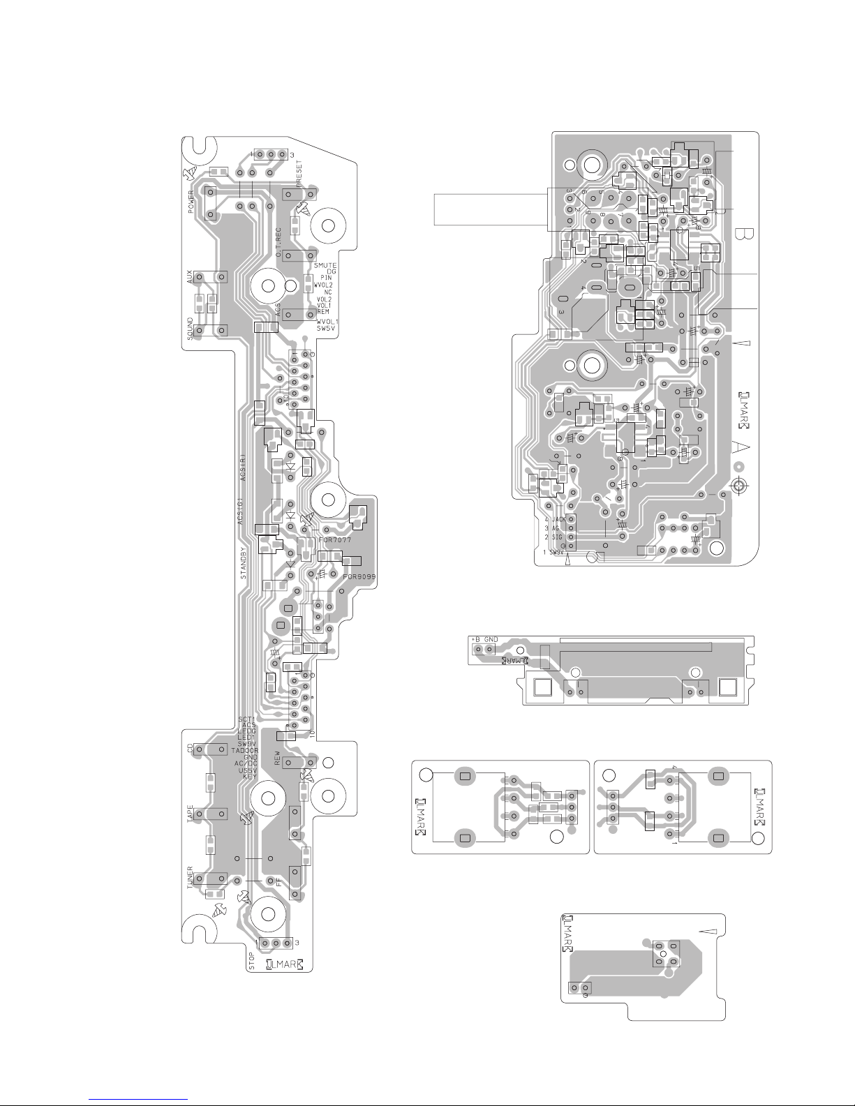
(Key board)
R2511
S2513
S2504
R2510
R2509
S2503
B4063
B4065
Q2501
FW253
B4064
R2501
Q2503
R2515
R2514
S2501
S2512
CN252
Q2505
D2502
R2512
B4013
D2503
D2504
Q2502
R2513
C2502
R2517
B4062
S2502
B4012
Q2504
(Guitar and Mic. jack board)
C7354
R7365
R7367
C7359
R7359
R7368
Q7355
C7352
R7353
VR731
Q7353
B7052
B7051
R7358
Q7351
R7354
Q7352
R7351
J7351
C7381
R7387
R7379
C7366
R7388
C7363
R7382
R7383
C7360
C7367
D7357
R7369
IC752
D7358
R7372
D7359
R7385
R7384
D7353
R7381
B7001
R7378
C7365
Q7359
D7355
D7351
R7370
Q7358
R7376
R7380
CN751
C7361
D7360
R7355
R7356
R7357
C7353
R7371
C7362
C7368
R7375
C7356
K7351
IC751
C7351
C7382
R7374
R7377
C7370
C7369
R7386
D7352
D7354
Q7357
C7355
Q7356
Q7354
R7362
Q7360
R7366
R7373
C7357
R7361
C7358
R7360
R7352
R2506
S2505
S2506
S2507
R2508
R2507
IC903
C2501
B4011
FW251
B4010
S2510
C2503
CN251
S2509
S2508
R2518
R2504
R2505
R2516
B4061
(LED board)
(Volume board)
VR901
FW402
C2521
C2522
D3573
D3571 D3572
(Woofer volume board)
R2519
R2520
R2521
FW252
FW254
(CD door switch board)
FW256
C2523 C2524
VR902
S2521
2-36
Page 70

CD servo control board (common)
Lead free solder used in the board (material : Sn-Ag-Cu, melting point : 219 Centigrade)
Forward side
C652
C677
C690
R833
R836
C691
R831
R850
R832
R851
R834
R838
R849
R278
C259
C251
R254
R295
R294
R293
R268
C261
C256
R253
R299
R835
IC201
R837
R840
C201
R839
R842
R841
R844
CN653
R843
R846
IC682
CN603
R672
X651
R845
IC681
R267
IC251
R260
R669
R671
R847
R264
C655
C672
C669
R848
R681
C660
R668
C676
R676
C678
R266
R675
R262
C253
C675
R261
R274
R662
R673
C671
R667
C673
R674
R263
R665R666
C668
R289
K654
R251
C674
R258
K651
C262
R259
R682
R655
R296
R256
CN651
D251
R265
R255
R231
R664
C667
C665
X251
C666
Q231
C233
R233
C234
C252
C291
Q232
C255
C664
R234
R232
C231 C232
K250
K252
K253
C654
IC671
IC651
R298
R271
R807
C653
K251
C663
C659
C662
C661
R653
R652
C651
R808
R678
Q291
R297
R830
C804
R651
R809
R805
D652
R814
R816
R812
C681
R661
R657
R659
C656
R235
R236
D252
R679
D654
D601
R631
R803
K254
Q654
R656
R817
C806
C813
C814
C805
R813
R804
C657
R654
C801
R658
C803
D655
R683
R801
CN652
C658
C624
C621
C644
IC601
R606
C622
R605
Q653
C617
R603
C607
R604
C808
C642
C605C606
Q651
R618
C643
R619
C616
R818
C802
Q652
R802
R617
C641
C608
FW602
R613
C615
R806
R611
C610
C614
C807
C612
C631
C611
C632
C623
R632
R634
R811
Q631
R815
C809
C811
R635
C633
IC801
C604
R602
C609
C603
R601
CN601
C602
C601
R623
R626
R607
R608
C625
R625
R621
C626
Reverse side
CN601
C631
TP2
FW602
C664
C666
K651
C673
CN651
C252
TP11
TP13
X251
TP12
TP14
TP15
TP19
C678
CN603
TP16
TP17
TP18
TP1
C624
TP601
TP623
TP653
TP622
C801
C622
C651
C291
CN652
2-37
Page 71

Cassette mechanism control board (common)
Lead free solder used in the board (material : Sn-Ag-Cu, melting point : 219 Centigrade)
(Switch board)
SW1
(Head amplifier board)
R351
Q303
B113
VR37
R315
C308
C309
C310
C314
R317
R316
RECLAGRECR
SW8V
R352
R313
B154
C313
SW2
PBLAGPBR
1
C315
MS
MB
CN34
C351
B107
C307
Q301
SW3
P1
D1
SW4
SW5
CN1
IC1
SW6
R371
B101
1
B152
MG
Q102
R114
C113
R110
R109
B151
B103
R113
C112
R112
R111
10
9
TW2
B166
CN33
R341
R342
B115
1
B114
NC
R343
R340
R213
C212
R212
R211
C211
TAP
Q202
R214
C213
R210
R209
RRE
SOL
C375
MG
5V
PHO
PLA
R375
Q372
FRE
70u
10
CN32
Q375
R372
R373
R376
C376
E
D375
B
Q376
B
Q371
E
C311
R327
1
6
VR31
VR32
R314
B111
Q311
C324
R325
Q310
Q302
C326
R322
C221
L301
3
R310
4
C325
C323
C321
Q308
C316
C317
Q309
C121
B112
C312
L303
D309
C322
Q307
Q306
R311
Q321
C320
C106
C319
C101
C102
R101
R305
Q305
C107
Q101
R102
C104
C318
R319
R335
B105
R103
Q304
R303
C110
R107
R121
R221
B104
C303
C103
C302
R108
R301
C108
9
B116
B117
TW1
C301
B157
C111
1
6
R304
8
B106
C109
C306
R116
IC32
R216
R205
R105
C205
C105
R204
R104
R106
9
C208
R206
C305
R208
C304
C207
B108
C201
C391
B109
R203
C210
R207
C204
R202
C202
R201
Q201
D301
C206
C209
16
1
CN31
B110
1
IC31
R332
R339
C203
R306
C333
C332
R333
C331
R334
R331
B162
16
1
C371
C374
R338
R337
R336
9
IC33
8
FW31
2-38
Page 72

Victor Company of Japan, Limited
Audio/Video Systems Category 10-1,1chome,Ohwatari-machi,Maebashi-city,371-8543,Japan
(No.MB519SCH)
Printed in Japan
VPT
Page 73
PARTS LIST
RV-NB10BJ,RV-NB10BC,
RV-NB10BB,RV-NB10BE,RV-NB10BEN,RV-NB10BEV,
RV-NB10WJ,RV-NB10WC,
RV-NB10WB,RV-NB10WE,RV-NB10WEN
* All printed circuit boards and its assemblies are not available as service parts.
- Contents -
Exploded view of general assembly and parts list (Block No.M1)
CD mechanism assembly and parts list (Block No.MB)
Cassette mechanism assembly and parts list (Block No.MP)
Electrical parts list (Block No.01~09)
Packing materials and accessories parts list (Block No.M3)
No.MB519
3- 2
3- 7
3- 9
3-11
3-30
3-1
Page 74

Exploded view of general assembly and parts list
e
2
3
9
1
Block No.
M
M
1
M
18
21
12
137
CD servo board
146
98
145
LED board
10
90
76
74
71
79
144
m
75
27
b
91
53
22
c
54
50
51
13
149
a
20
73
52
89
92
66
f
69
m
14
67
23
72
51
30
53
68
77
79
49
51
148
13
36
70
15
u
35
65
64
47
f
53
61
63
62
B
48
52
n
147
t
78
57
58
48
46
45
52
g
150
55
Display/Control
board
51
56
53
34
37
58
Guitar and Mic. jack
board
n
44
46
47
48
48
2
31
44
A
31
129
129
45
g
19
44
43
16
17
129
v
11
16
20
21
129
128
131
131
132
7
k1
133
9
95
9
Tuner board
3
4
Equalizer amplifi
board
a
c
b
6
41
157
114
82
1
i
3
r
r
11
8
11
Key board
17
11
41
11
11
s
41
25
s
8
39
40
Power supply
board
24
143
v
o
26
o
21
2
33
3-2
29
28
38
32
21
1
Page 75

112
113
8
131
131
2
9
95
9
Tuner board
Equalizer amplifier
board
39
40
Power supply
board
24
26
o
41
b
157
c
k1
133
114
82
107
110
115
117
117
125
113
113
111
h
81
88
80
Power amplifier board
k2
k1
108
87
110
86
88
84
111
85
109
85
86
85
86
110
155
130
110
116
C
87
94
126
97
A
a
96
B
114
127
93
108
134
134
135
134
59
60
i2
134
C
135
134
84
134
156
136
u
t
134
121
i1
120
133
132
131
131
154
128
129
114
i2
42
105
141
w
h
83
i1
140
104
103
142
158
122
118
124
x
99
99
119
w
152
153
k2
x
139
151
9
100
130
132
102
3
106
3
9
129
129
2
6
5
7
7
3-3
Page 76

General Assembly
Block No. [M][1][M][M]
Symbol No. Part No. Part Name Description Local
1 VJG1500-00JUL FRONT CABI SA NB10BJ,NB10BC
1 VJG1500-00K FRONT CABI SA NB10BB,NB10BE,NB10BEN,NB10BEV
1 VJG1500-00LUL FRONT CABI SA NB10WJ,NB10WC
1 VJG1500-00M FRONT CABI SA NB10WB,NB10WE,NB10WEN
2 LE10008-024A SPEAKER (x2)
3 QYSBSF3010ZA TAP SCREW M3 x 10mm(x8)
4 VYH2280-002 CAP (L)
5 VYH2281-002 CAP (R)
6 VKZ4389-009 SOUND ABSOBER (x2)
7 VKZ4805-001UL SOUND ABSOBER (x2) NB10BB,NB10BE,NB10BEN,NB10BEV,NB10WB,NB10WE,NB10WEN
8 VYSH102-097 SPACER (x2)
9 QYSBSF3010ZA TAP SCREW M3 x 10mm(x8)
10 VJD2495-071 FRONT COVER(A) NB10BJ,NB10BC
10 VJD2495-072 FRONT COVER(A) NB10BB,NB10BE,NB10BEN,NB10BEV
10 VJD2495-081 FRONT COVER(A) NB10WJ,NB10WC
10 VJD2495-082 FRONT COVER(A) NB10WB,NB10WE,NB10WEN
11 QYSBSF2608ZA TAP SCREW M2.6 x 8mm(x10)
12 VJK4520-101 LCD LENS NB10BJ,NB10BC,NB10BB,NB10BE,NB10BEN,NB10BEV
12 VJK4520-111 LCD LENS NB10WJ,NB10WC,NB10WB,NB10WE,NB10WEN
13 VYSH102-098 SPACER (x2)
14 VXP3890-061 POWER BUTTON(A) NB10BJ,NB10BC,NB10BB,NB10BE,NB10BEN,NB10BEV
14 VXP3890-011 POWER BUTTON(A) NB10WJ,NB10WC,NB10WB,NB10WE,NB10WEN
15 VXP3891-071 FUNC. BTN(A) NB10BJ,NB10BC
15 VXP3891-072 FUNC. BTN(A) NB10BB,NB10BE,NB10BEN,NB10BEV
15 VXP3891-081 FUNC. BTN(A) NB10WJ,NB10WC
15 VXP3891-082 FUNC. BTN(A) NB10WB,NB10WE,NB10WEN
16 VXL4455-061 VOL.KNOB (x2) NB10BJ,NB10BC,NB10BB,NB10BE,NB10BEN,NB10BEV
16 VXL4455-071 VOL.KNOB (x2) NB10WJ,NB10WC,NB10WB,NB10WE,NB10WEN
17 VYTS539-003 VOL.SHEET (x2)
18 VJF3007-061 FOOT NB10BJ,NB10BC,NB10BB,NB10BE,NB10BEN,NB10BEV
18 VJF3007-011 FOOT NB10WJ,NB10WC,NB10WB,NB10WE,NB10WEN
19 VJF3007-062 FOOT NB10BJ,NB10BC,NB10BB,NB10BE,NB10BEN,NB10BEV
19 VJF3007-012 FOOT NB10WJ,NB10WC,NB10WB,NB10WE,NB10WEN
20 VYSA1R6-079 SPACER (x2)
21 QYSBSF3010ZA TAP SCREW M3 x 10mm(x6)
22 VJK4516-002 LENS
23 VJD5512-001 LED LENS
24 VYTH539-002 PACKING SHEET L
25 VYTH540-002 PACKING SHEET R
26 QYSBSFG3010ZA TAP SCREW M3 x 10mm
27 PQ45130-7 JVC MARK
28 VJT2389-041 CASSETTE HOLDER NB10BJ,NB10BC,NB10BB,NB10BE,NB10BEN,NB10BEV
28 VJT2389-061 CASSETTE HOLDER NB10WJ,NB10WC,NB10WB,NB10WE,NB10WEN
29 VJT2390-061 DOOR COVER NB10BJ,NB10BC,NB10BB,NB10BE,NB10BEN,NB10BEV
29 VJT2390-071 DOOR COVER NB10WJ,NB10WC,NB10WB,NB10WE,NB10WEN
30 VJT4246-091 DOOR LENS NB10BJ,NB10BC,NB10BB,NB10BE,NB10BEN,NB10BEV
30 VJT4246-101 DOOR LENS NB10WJ,NB10WC,NB10WB,NB10WE,NB10WEN
31 VKY4180-401 CASSETTE SPRING (x2)
32 VYH5601-001 GEAR
33 VXL4458-061 EJECT KNOB NB10BJ,NB10BC,NB10BB,NB10BE,NB10BEN,NB10BEV
33 VXL4458-011 EJECT KNOB NB10WJ,NB10WC,NB10WB,NB10WE,NB10WEN
34 VYH8174-001 CAM(A)
35 VKY4736-001 PLATE SPRING(A)
36 VKY4737-002 PLATE SPRING(B)
37 QYSBSF2008ZA TAP SCREW M2 x 8mm
38 VKW5309-001 DOOR SPRING
39 VKL7850-303 EJECT SAFTY(R)
40 VKW5258-003 TORSION SPRING
41 QYSBSF3014ZA TAP SCREW M3 x 14mm(x4)
42 VMA4728-003 HEAD SHIELD
43 LV34126-002A PICK COVER
44 QYSDSF2006NA TAP SCREW M2 x 6mm(x4)
45 FMYH4003-003 INSULATOR (x2)
46 FMYH4003-004 INSULATOR (x2)
47 VYH7815-001 CD MECHA HOLDER (x2)
48 QYSBSF3010ZA TAP SCREW M3 x 10mm(x4)
49 E65923-009 TAPPING SCREW
50 LV10179-002A CD CASE NB10BJ,NB10BC,NB10BB,NB10BE,NB10BEN,NB10BEV
50 LV10179-005A CD CASE NB10WJ,NB10WC,NB10WB,NB10WE,NB10WEN
51 LV30226-039A SPACER (x6) NB10BB,NB10BE,NB10BEN,NB10BEV,NB10WB,NB10WE,NB10WEN
52 QYSBSF3010ZA TAP SCREW M3 x 10mm(x4)
53 QYSBSF3010ZA TAP SCREW M3 x 10mm(x4)
54 VYH4769-002SS GEAR
55 LV35863-001A SHIELD A NB10BB,NB10BE,NB10BEN,NB10BEV,NB10WB,NB10WE,NB10WEN
3-4
Page 77

Symbol No. Part No. Part Name Description Local
56 LV35864-001A SHIELD B NB10BB,NB10BE,NB10BEN,NB10BEV,NB10WB,NB10WE,NB10WEN
57 LV40779-001A BRACKET
58 QYSBSF3010ZA TAP SCREW M3 x 10mm(x3)
59 LV40759-001A KNOB
60 LV40760-001A MIC PLATE
61 VJT1060-071 CD DOOR NB10BJ,NB10BC,NB10BB,NB10BE,NB10BEN,NB10BEV
61 VJT1060-081 CD DOOR NB10WJ,NB10WC,NB10WB,NB10WE,NB10WEN
62 LV35263-001A CLAMPER
63 LV42929-001A P.C.MAGNET
64 VYH7314-001 YOKE
65 LV43667-001A CLAMPER WEIGHT
66 VXL4458-061 EJECT KNOB NB10BJ,NB10BC,NB10BB,NB10BE,NB10BEN,NB10BEV
66 VXL4458-011 EJECT KNOB NB10WJ,NB10WC,NB10WB,NB10WE,NB10WEN
67 VYH8197-001 CAM(B)
68 QYSBSF2008ZA TAP SCREW M2 x 8mm
69 VKY4736-001 PLATE SPRING(A)
70 VKY4737-002 PLATE SPRING(B)
71 VYH8178-001 SLIDER(B)
72 VKW5334-001 SWITCH SPRING
73 VYH8204-001 SWITCH LEVER
74 VYH8205-001 LOCK
75 QYSDSF2606MA TAP SCREW M2.6 x 6mm
76 VYH8176-003 COVER
77 VKW5352-001 TENSION SPRING
78 VKW5335-002 CD DOOR SPRING
79 VKZ4794-003 SPECIAL SCREW (x3)
80 VMH3021-001 HEAT SINK
81 VYH3892-005 HEAT SINK
82 VMH4055-002 HEAT SINK
83 QYSBSF3010ZA TAP SCREW M3 x 10mm
84 QYSBSF3010ZA TAP SCREW M3 x 10mm(x2)
85 QYSBSF3010ZA TAP SCREW M3 x 10mm(x4)
86 QYSBST3008ZA TAP SCREW M3 x 8mm(x4)
87 VYH8188-002 BRACKET (x2)
88 QYSBSF3010ZA TAP SCREW M3 x 10mm(x4)
89 LV35225-001A LCD HOLDER
90 LV43895-001A SHEET
91 LV43896-001A LED HOLDER
92 QYSDSF2608ZA TAP SCREW M2.6 x 8mm(x2)
93 VJG1502-081UL REAR CABI NB10BJ,NB10BC
93 VJG1502-082 REAR CABI NB10BB,NB10BE,NB10BEN,NB10BEV
93 VJG1502-091UL REAR CABI NB10WJ,NB10WC
93 VJG1502-092 REAR CABI NB10WB,NB10WE,NB10WEN
94 QZW0152-001 ROD ANTENNA
95 VYH5012-005 TERMINAL LUG
96 E65923-009 TAPPING SCREW
97 QYSDSP3012NA SCREW M3 x 12mm
98 VYSH101-009 SPACER (x2)
99 QYSBSF4012ZA TAP SCREW M4 x 12mm(x4)
100 VYSH101-028 SPACER
102 VYH8179-004 JACK HOLDER NB10BJ,NB10BC,NB10WJ,NB10WC
102 VYH8179-005 JACK HOLDER NB10BB,NB10BE,NB10BEN,NB10BEV,NB10WB,NB10WE,NB10WEN
103 VYTH543-001 SHEET(AC)
104 VYTH544-001 SHEET(DC)
105 VYSA1R6-080 SPACER
106 QYSBSF3010ZA TAP SCREW M3 x 10mm(x2)
107 VJD2503-061UL DUCT NB10BJ,NB10BC,NB10BB,NB10BE,NB10BEN,NB10BEV
107 VJD2503-071UL DUCT NB10WJ,NB10WC,NB10WB,NB10WE,NB10WEN
108 VKZ4796-003 SOUND ABSOBER (x2)
109 VJD2503-062UL DUCT NB10BJ,NB10BC,NB10BB,NB10BE,NB10BEN,NB10BEV
109 VJD2503-072UL DUCT NB10WJ,NB10WC,NB10WB,NB10WE,NB10WEN
110 QYSBSF3010ZA TAP SCREW M3 x 10mm(x8)
111 VJD5510-061 DUCT CAP (x2) NB10BJ,NB10BC,NB10BB,NB10BE,NB10BEN,NB10BEV
111 VJD5510-011 DUCT CAP (x2) NB10WJ,NB10WC,NB10WB,NB10WE,NB10WEN
112 VJD1230-043UL GRILLE NB10BJ,NB10BC
112 VJD1230-042UL GRILLE NB10BB,NB10BE,NB10BEN,NB10BEV
112 VJD1230-071UL GRILLE NB10WJ,NB10WC
112 VJD1230-072UL GRILLE NB10WB,NB10WE,NB10WEN
113 QYSBSF3010ZA TAP SCREW M3 x 10mm(x4)
114 QYSBSF3010ZA TAP SCREW M3 x 10mm(x4)
115 VJE3036-041 BATT.LID NB10BJ,NB10BC,NB10BB,NB10BE,NB10BEN,NB10BEV
115 VJE3036-071 BATT.LID NB10WJ,NB10WC,NB10WB,NB10WE,NB10WEN
116 VYSA1R4-056 SPACER
117 QYSBSF3010ZA TAP SCREW M3 x 10mm(x2)
118 VYH8199-041 COVER NB10BJ,NB10BC,NB10BB,NB10BE,NB10BEN,NB10BEV
118 VYH8199-071 COVER NB10WJ,NB10WC,NB10WB,NB10WE,NB10WEN
119 VYTH542-001 SHEET(COVER)
120 VYSH101-029 SPACER
3-5
Page 78

Symbol No. Part No. Part Name Description Local
121 VYSH101-027 SPACER
122 QYSBSF3010ZA TAP SCREW M3 x 10mm
124 QYSBSF3010ZA TAP SCREW M3 x 10mm
125 VJC2603-041 BATTERY COVER NB10BJ,NB10BC,NB10BB,NB10BE,NB10BEN,NB10BEV
125 VJC2603-071 BATTERY COVER NB10WJ,NB10WC,NB10WB,NB10WE,NB10WEN
126 VYH5657-001 BATTERY SPRING
127 E65923-009 TAPPING SCREW
128 VJD1233-00JUL SIDE PROTECT.AS (x2) NB10BJ,NB10BC
128 VJD1233-00M SIDE PROTECT.AS (x2) NB10BB,NB10BE,NB10BEN,NB10BEV
128 VJD1233-00KUL SIDE PROTECT.AS (x2) NB10WJ,NB10WC
128 VJD1233-00N SIDE PROTECT.AS (x2) NB10WB,NB10WE,NB10WEN
129 VKZ4795-012 SPECIAL SCREW (x12)
130 LE10016-057A SPEAKER (x2)
131 QYSBSF4012ZA TAP SCREW M4 x 12mm(x4)
132 QYSBSF4012ZA TAP SCREW M4 x 12mm(x4)
133 VKH3012-073 SHAFT(E) (x2)
134 QYSBSF3035ZA TAP SCREW M3 x 35mm(x10)
135 QYSBSF3010ZA TAP SCREW M3 x 10mm(x2)
136 LV36890-001A RATING LABEL NB10BJ,NB10BC
136 LV36890-002A RATING LABEL NB10BB,NB10BE,NB10BEN
136 LV36890-003A RATING LABEL NB10BEV
136 LV36891-001A RATING LABEL NB10WJ,NB10WC
136 LV36891-002A RATING LABEL NB10WB,NB10WE,NB10WEN
137 LV42035-002A LASER CAUTION
139 QQT0508-002 POWER TRANSF T1901 NB10BJ,NB10BC,NB10WJ,NB10WC
139 QQT0508-001 POWER TRANSF T1901 NB10BB,NB10BE,NB10BEN,NB10BEV,NB10WB,NB10WE,NB10WEN
140 QMF51U2-1R25-J8 FUSE F1901 1.25A AC250V NB10BJ,NB10BC,NB10WJ,NB10WC
140 QMF51W2-R63-J8 FUSE F1901 0.63A AC250V NB10BB,NB10BE,NB10BEN,NB10BEV,NB10WB,NB10WE,NB10WEN
141 QMF51U1-8R0-J8 FUSE F1902 8A AC125V NB10BJ,NB10BC,NB10WJ,NB10WC
141 QMFZ031-8R0-J1 FUSE F1902 8A NB10BB,NB10BE,NB10BEN,NB10BEV,NB10WB,NB10WE,NB10WEN
142 QMF51U1-6R3-J8 FUSE F1904 6.3A AC125V NB10BJ,NB10BC,NB10WJ,NB10WC
142 QMF51W2-6R3-J8 FUSE F1904 6.3A AC250V NB10BB,NB10BE,NB10BEN,NB10BEV,NB10WB,NB10WE,NB10WEN
143 WJJ0002-001A-E E-SI C WIRE C-C
144 QUQQ12-0912CJ-E FFC WIRE 9pin 12cm
145 QUQQ12-0916CJ-E FFC WIRE 9pin 16cm
146 QUQQ12-1018CJ-E FFC WIRE 10pin 18cm
147 QUQQ12-1310CJ-E FFC WIRE 13pin 10cm
148 QUQQ12-1310CJ-E FFC WIRE 13pin 10cm
149 QUQW10-1712AJ-E FFC WIRE 17pin 12cm
150 QUQW10-1607AJ-E FFC WIRE 16pin 7cm
151 VYK3023-001 SHIELD NB10BJ,NB10BC,NB10WJ,NB10WC
152 VYSA1R6-079 SPACER (x2) NB10BJ,NB10BC,NB10WJ,NB10WC
153 LV30225-0X7A SPACER NB10BJ,NB10BC,NB10WJ,NB10WC
154 VND4113-001 G.CAUTION NB10BJ,NB10BC,NB10WJ,NB10WC
155 LV43835-001A EMC LABEL NB10BJ,NB10BC,NB10WJ,NB10WC
156 QXTG109-010 GLASS TUBE (x2) NB10BJ,NB10BC,NB10WJ,NB10WC
157 LV43517-001A FUSE CAUTION NB10BJ,NB10BC,NB10WJ,NB10WC
158 QMF51U1-6R3-J8 FUSE F1903 6.3A AC125V NB10BJ,NB10BC,NB10WJ,NB10WC
3-6
Page 79

CD mechanism assembly and parts list
FXL-M73-2M
Grease & Bond
= JVG-31N
15
1
2
4
5
Block No.
3
7
6
M
M
B
M
6
8
9
13
10
8
1
10
19.4 0.1mm
12
11
14
The parts without symbol number are not service.
3-7
Page 80

CD mechanism
Symbol No. Part No. Part Name Description Local
1 LV10723-002A CD MECHA BASE A
2 OPTIMA-73B2 CD PICK
3 E406777-002SM C.D SHAFT
4 LV31002-001A CD RACK
5 E307745-441SM C.D GEAR 3
6 QYSDSP2003N SCREW M2 x 3mm(x4)
7 E406750-442SM PINION
8 LV43119-002A T.T PACKING
9 QAR0253-001 FEED MOTOR
10 QAR0130-001 SP MOTOR
11 EMW10190-441 CIR BOARD
12 QGA2001F1-06 CONNECTOR W-B (1-6)
13 QSW0506-001 LEAF SWITCH
14 E75832-221SS SPECIAL SCREW
15 QYSDSF2006Z SCREW M2 x 6mm
Block No. [M][B][M][M]
3-8
Page 81

Cassette mechanism assembly and parts list
SLC-S41M
Block No.
M
P
MM
Grease
=EM-30L
=UD-24
=LEN-320M
=Mobil-1
33
1
26
A
18
7
2
2
9
8
3
4
12
11
22
3
5
10
6
28
B
23
5
Cassette switch
1
The lower side
board
29
24
17
21
10
20
19
16
30
25
32
31
0.1
0.15 mm
8.7
32
31
34
27
Head amplifier &
Mechanism control board
34
The parts without symbol number are not service.
3-9
Page 82

Cassette mechanism
Symbol No. Part No. Part Name Description Local
1 VKS1165-00N CHASSIS B. ASSY
2 VKS2274-002 REEL GEAR (x2)
3 VKW5286-002 B.T. SPRING (x2)
4 VKS5559-001 PLAY IDLE GEAR
5 VKS5595-002 BLIND
6 LV42013-001A EARTH SPRING
7 SLC-RP1SVM HEAD MOUNT ASSY
8 VKY3149-002 CASSETTE SP.
9 VKM3906-004 PLAY SW.LEVER
10 VKS1166-003 CONTROL CAM
11 VKW5279-002 HEAD BASE SP(R)
12 VKW5280-001 HEAD BASE SP(L)
16 VKS5603-00H MAIN PULLEY ASY
17 VKS3785-001MM FR ARM
18 VKW5284-002 SWING SPRING
19 VKS2278-003 TRIGGER ARM
20 VKW5301-001 FR SPRING
21 VKW5266-001 ELEVATOR SPRING
22 WDL214035-2 SLIT WASHER
23 QYSBSF2005ZA TAP SCREW M2 x 5mm
24 VKS3786-00G CLUTCH ASSY
25 VKF3205-00B F.WHEEL ASSY(R)
26 WDL183425 SLIT WASHER
27 VKF3207-00C F.WHEEL ASSY(L)
28 WDL173525-6 SLIT WASHER
29 VKZ3174-00A DC SOLENOID
30 LV42836-001A CAPSTAN BELT
31 QAR0309-001 D.C.MOTOR
32 VKR4761-003 MOTOR PULLEY
33 QYSPSP2604ZA SCREW M2.6 x 4mm(x2)
34 QYSBSF2608ZA TAP SCREW M2.6 x 8mm(x3)
Block No. [M][P][M][M]
3-10
Page 83

Electrical parts list
Symbol No.
Part No. Part Name Description Local
Main board (J,C ver.)
Symbol No.
IC301 TA8233BH IC
IC390 KIA78DL06PI IC
IC601 TA8223K IC
IC701 BA15218N IC
IC702 BA15218N IC
IC703 BA15218N IC
IC704 BA15218N IC
IC801 BA15218N IC
Q3191 KRA110M-T TRANSISTOR
Q3192 2SA1359/OY/ TRANSISTOR
Q3193 KRA111M-T DIGI TRANSISTOR
Q3194 KTC3199/GL/-T TRANSISTOR
Q3195 KTA1267/YG/-T TRANSISTOR
Q3196 KTA1023/OY/-T TRANSISTOR
Q3197 KTC3199/GL/-T TRANSISTOR
Q3198 KRC111M-T TRANSISTOR
Q3301 KTA1267/YG/-T TRANSISTOR
Q3302 2SA1359/OY/ TRANSISTOR
Q3303 KRA114M-T DIGI TRANSISTOR
Q3304 KRC114M-T TRANSISTOR
Q3305 KTC3199/GL/-T TRANSISTOR
Q3306 KTC3199/GL/-T TRANSISTOR
Q3491 KTA1267/YG/-T TRANSISTOR
Q3492 KTA1046/Y/ TRANSISTOR *
Q3493 KRA114M-T DIGI TRANSISTOR
Q3494 KRC114M-T TRANSISTOR
Q3495 KTC3199/GL/-T TRANSISTOR
Q3496 KTC3199/GL/-T TRANSISTOR
Q6101 KTC3203/OY/-T TRANSISTOR
Q6201 KTC3203/OY/-T TRANSISTOR
Q6301 2SA952/LK/-T TRANSISTOR
Q6302 KTC3199/GL/-T TRANSISTOR
Q6303 KRA102M-T DIGI TRANSISTOR
Q6304 KTC3203/OY/-T TRANSISTOR
Q6305 KRC102M-T DIGI TRANSISTOR
Q6306 KRC102M-T DIGI TRANSISTOR
Q6307 KRC102M-T DIGI TRANSISTOR
Q6308 KRC102M-T DIGI TRANSISTOR
Q7301 KTC3199/GL/-T TRANSISTOR
Q7302 KTC3199/GL/-T TRANSISTOR
Q7303 2SK301/R/-T JUNCTION FET
Q8101 KTC3199/GL/-T TRANSISTOR
Q8201 KTC3199/GL/-T TRANSISTOR
D8 SVC344-T VARI CAP
D1901 TS6P05G-07 SI DIODE
D1902 6A10E2 SI DIODE
D3191 1SS133-T2 SI DIODE
D3192 MTZJ7.5A-T2 Z DIODE
D3193 SRT14 DIODE
D3194 MTZJ7.5A-T2 Z DIODE
D3195 1SS133-T2 SI DIODE
D3196 1SS133-T2 SI DIODE
D3301 1SS133-T2 SI DIODE
D3302 MTZJ9.1A-T2 Z DIODE
D3491 1SS133-T2 SI DIODE
D3492 MTZJ9.1A-T2 Z DIODE
D3493 1SS133-T2 SI DIODE
D3901 MTZJ8.2B-T2 Z DIODE
D6301 1SS133-T2 SI DIODE
D6302 1SS133-T2 SI DIODE
D6304 1SS133-T2 SI DIODE
D7301 1SS133-T2 SI DIODE
D7302 1SS133-T2 SI DIODE
D7303 1SS133-T2 SI DIODE
D7304 1SS133-T2 SI DIODE
D7305 1SS133-T2 SI DIODE
D7306 1SS133-T2 SI DIODE
D7307 MTZJ4.3B-T2 Z DIODE
Part No. Part Name Description Local
Block No. [0][1]
D8301 MTZJ4.3B-T2 Z DIODE
C1901 QFLC1HJ-683Z M CAPACITOR 0.068uF 50V J
C1902 QFLC1HJ-683Z M CAPACITOR 0.068uF 50V J
C1903 QFLC1HJ-683Z M CAPACITOR 0.068uF 50V J
C1904 QFLC1HJ-683Z M CAPACITOR 0.068uF 50V J
C3191 QETN1HM-475Z E CAPACITOR 4.7uF 50V M
C3192 QETN1EM-107Z E CAPACITOR 100uF 25V M
C3193 QCBB1HK-101Y C CAPACITOR 100pF 50V K
C3194 QETN1EM-107Z E CAPACITOR 100uF 25V M
C3301 QDYB1CM-103Y C CAPACITOR 0.01uF 16V M
C3302 QCBB1HK-221Y C CAPACITOR 220pF 50V K
C3303 QETN1CM-107Z E CAPACITOR 100uF 16V M
C3491 QDYB1CM-103Y C CAPACITOR 0.01uF 16V M
C3492 QCBB1HK-221Y C CAPACITOR 220pF 50V K
C3493 QETN1CM-107Z E CAPACITOR 100uF 16V M
C3901 QETN1CM-107Z E CAPACITOR 100uF 16V M
C3902 QFLC1HJ-104Z M CAPACITOR 0.1uF 50V J
C5308 QER61HM-474Z E CAPACITOR 0.47uF 50V M
C6101 QFVF1HJ-224Z MF CAPACITOR 0.22uF 50V J
C6102 QCBB1HK-151Y C CAPACITOR 150pF 50V K
C6103 QETN1EM-107Z E CAPACITOR 100uF 25V M
C6104 QFVF1HJ-104Z MF CAPACITOR 0.1uF 50V J
C6105 QETN1EM-476Z E CAPACITOR 47uF 25V M
C6106 QETN1EM-108Z E CAPACITOR 1000uF 25V M
C6107 QTE1V06-226Z E CAPACITOR 22uF 35V
C6201 QFVF1HJ-224Z MF CAPACITOR 0.22uF 50V J
C6202 QCBB1HK-151Y C CAPACITOR 150pF 50V K
C6203 QETN1EM-107Z E CAPACITOR 100uF 25V M
C6204 QFVF1HJ-104Z MF CAPACITOR 0.1uF 50V J
C6205 QETN1EM-476Z E CAPACITOR 47uF 25V M
C6206 QETN1EM-108Z E CAPACITOR 1000uF 25V M
C6207 QTE1V06-226Z E CAPACITOR 22uF 35V
C6301 QETN1EM-227Z E CAPACITOR 220uF 25V M
C6302 QETN1HM-106Z E CAPACITOR 10uF 50V M
C6303 QFVF1HJ-104Z MF CAPACITOR 0.1uF 50V J
C6304 QFVF1HJ-154Z MF CAPACITOR 0.15uF 50V J
C6305 QETN1HM-105Z E CAPACITOR 1uF 50V M
C6306 QETN1AM-227Z E CAPACITOR 220uF 10V M
C6307 QETN1HM-106Z E CAPACITOR 10uF 50V M
C6308 QETN1HM-474Z E CAPACITOR 0.47uF 50V M
C6309 QETN1HM-474Z E CAPACITOR 0.47uF 50V M
C6310 QCBB1HK-101Y C CAPACITOR 100pF 50V K
C6311 QETN1HM-106Z E CAPACITOR 10uF 50V M
C6312 QETN1EM-227Z E CAPACITOR 220uF 25V M
C6313 QCBB1HK-101Y C CAPACITOR 100pF 50V K
C6314 QFVF1HJ-104Z MF CAPACITOR 0.1uF 50V J
C6315 QETM1EM-688 E CAPACITOR 6800uF 25V M
C6316 QFVF1HJ-104Z MF CAPACITOR 0.1uF 50V J
C6317 QFVF1HJ-104Z MF CAPACITOR 0.1uF 50V J
C6318 QFVF1HJ-104Z MF CAPACITOR 0.1uF 50V J
C6319 QFVF1HJ-104Z MF CAPACITOR 0.1uF 50V J
C6320 QETN1HM-106Z E CAPACITOR 10uF 50V M
C6321 QETN1HM-106Z E CAPACITOR 10uF 50V M
C7301 QETN1CM-107Z E CAPACITOR 100uF 16V M
C7302 QETN1HM-474Z E CAPACITOR 0.47uF 50V M
C7303 QCSB1HK-3R3Y C CAPACITOR 3.3pF 50V K
C7305 QETN1HM-475Z E CAPACITOR 4.7uF 50V M
C7306 QFVF1HJ-274Z MF CAPACITOR 0.27uF 50V J
C7307 QETN1HM-475Z E CAPACITOR 4.7uF 50V M
C7308 QFLC1HJ-103Z M CAPACITOR 0.01uF 50V J
C7309 QETN1CM-107Z E CAPACITOR 100uF 16V M
C7310 QFLC1HJ-153Z M CAPACITOR 0.015uF 50V J
C7311 QETN1HM-475Z E CAPACITOR 4.7uF 50V M
C7312 QETN1HM-105Z E CAPACITOR 1uF 50V M
C7313 QETN1HM-475Z E CAPACITOR 4.7uF 50V M
C7314 QETN1CM-107Z E CAPACITOR 100uF 16V M
C7316 QETN1HM-475Z E CAPACITOR 4.7uF 50V M
C7317 QFVF1HJ-104Z MF CAPACITOR 0.1uF 50V J
C7318 QETN1CM-107Z E CAPACITOR 100uF 16V M
C7319 QFVF1HJ-104Z MF CAPACITOR 0.1uF 50V J
C7320 QFLC1HJ-393Z M CAPACITOR 0.039uF 50V J
C7321 QFVF1HJ-154Z MF CAPACITOR 0.15uF 50V J
C7322 QER61HM-105Z E CAPACITOR 1uF 50V M
C7323 QETN1HM-106Z E CAPACITOR 10uF 50V M
C7324 QETN1HM-475Z E CAPACITOR 4.7uF 50V M
3-11
Page 84

Symbol No.
Part No. Part Name Description Local
Symbol No.
Part No. Part Name Description Local
C8101 QFLC1HJ-563Z M CAPACITOR 0.056uF 50V J
C8102 QFLC1HJ-563Z M CAPACITOR 0.056uF 50V J
C8103 QETN1EM-476Z E CAPACITOR 47uF 25V M
C8201 QFLC1HJ-563Z M CAPACITOR 0.056uF 50V J
C8202 QFLC1HJ-563Z M CAPACITOR 0.056uF 50V J
C8203 QETN1EM-476Z E CAPACITOR 47uF 25V M
C8301 QETN1EM-476Z E CAPACITOR 47uF 25V M
C8303 QETN1HM-105Z E CAPACITOR 1uF 50V M
C8322 QETN1EM-476Z E CAPACITOR 47uF 25V M
TC2 QAT3725-200Z TRIM CAPACITOR 20pF
R37 QRE141J-560Y C RESISTOR 56Ω 1/4W J
R64 QRE141J-102Y C RESISTOR 1kΩ 1/4W J
R1901 QRE141J-103Y C RESISTOR 10kΩ 1/4W J
R3191 QRE141J-1R5Y C RESISTOR 1.5Ω 1/4W J
R3192 QRE141J-152Y C RESISTOR 1.5kΩ 1/4W J
R3193 QRE141J-104Y C RESISTOR 100kΩ 1/4W J
R3194 QRE141J-103Y C RESISTOR 10kΩ 1/4W J
R3195 QRE141J-222Y C RESISTOR 2.2kΩ 1/4W J
R3196 QRE141J-103Y C RESISTOR 10kΩ 1/4W J
R3197 QAD0015-153Z THERMISTOR 15k
R3198 QRE141J-472Y C RESISTOR 4.7kΩ 1/4W J
R3199 QRE141J-473Y C RESISTOR 47kΩ 1/4W J
R3200 QRE141J-123Y C RESISTOR 12kΩ 1/4W J
R3201 QRE141J-152Y C RESISTOR 1.5kΩ 1/4W J
R3202 QRE141J-152Y C RESISTOR 1.5kΩ 1/4W J
R3203 QRE141J-103Y C RESISTOR 10kΩ 1/4W J
R3204 QRE141J-222Y C RESISTOR 2.2kΩ 1/4W J
R3301 QRE141J-471Y C RESISTOR 470Ω 1/4W J
R3302 QRE141J-1R0Y C RESISTOR 1Ω 1/4W J
R3303 QRE141J-1R0Y C RESISTOR 1Ω 1/4W J
R3304 QRE141J-1R0Y C RESISTOR 1Ω 1/4W J
R3305 QRE141J-222Y C RESISTOR 2.2kΩ 1/4W J
R3306 QRE141J-682Y C RESISTOR 6.8kΩ 1/4W J
R3307 QRE141J-102Y C RESISTOR 1kΩ 1/4W J
R3308 QRE141J-222Y C RESISTOR 2.2kΩ 1/4W J
R3309 QRE141J-681Y C RESISTOR 680Ω 1/4W J
R3310 QRE141J-681Y C RESISTOR 680Ω 1/4W J
R3311 QRE141J-681Y C RESISTOR 680Ω 1/4W J
R3312 QRE141J-472Y C RESISTOR 4.7kΩ 1/4W J
R3313 QRE141J-471Y C RESISTOR 470Ω 1/4W J
R3314 QRE141J-332Y C RESISTOR 3.3kΩ 1/4W J
R3315 QRE141J-472Y C RESISTOR 4.7kΩ 1/4W J
R3316 QRE141J-472Y C RESISTOR 4.7kΩ 1/4W J
R3491 QRE141J-471Y C RESISTOR 470Ω 1/4W J
R3492 QRE141J-1R0Y C RESISTOR 1Ω 1/4W J
R3493 QRE141J-1R0Y C RESISTOR 1Ω 1/4W J
R3494 QRE141J-1R0Y C RESISTOR 1Ω 1/4W J
R3495 QRE141J-222Y C RESISTOR 2.2kΩ 1/4W J
R3496 QRE141J-682Y C RESISTOR 6.8k
R3497 QRE141J-102Y C RESISTOR 1kΩ 1/4W J
R3498 QRE141J-222Y C RESISTOR 2.2k
R3499 QRE141J-681Y C RESISTOR 680
R3500 QRE141J-681Y C RESISTOR 680Ω 1/4W J
R3501 QRE141J-681Y C RESISTOR 680
R3502 QRE141J-472Y C RESISTOR 4.7k
R3503 QRE141J-471Y C RESISTOR 470Ω 1/4W J
R3504 QRE141J-332Y C RESISTOR 3.3k
R3505 QRE141J-472Y C RESISTOR 4.7kΩ 1/4W J
R3506 QRE141J-472Y C RESISTOR 4.7k
R3507 QRE141J-332Y C RESISTOR 3.3k
R3508 QRE141J-682Y C RESISTOR 6.8kΩ 1/4W J
R3901 QRE141J-5R6 C RESISTOR 5.6
R5107 QRE141J-104Y C RESISTOR 100k
R5207 QRE141J-104Y C RESISTOR 100kΩ 1/4W J
R6101 QRE141J-273Y C RESISTOR 27k
R6102 QRE141J-121Y C RESISTOR 120
R6103 QRE141J-123Y C RESISTOR 12k
R6104 QRE141J-2R2Y C RESISTOR 2.2
R6105 QRE141J-472Y C RESISTOR 4.7kΩ 1/4W J
R6201 QRE141J-273Y C RESISTOR 27k
R6202 QRE141J-121Y C RESISTOR 120
R6203 QRE141J-123Y C RESISTOR 12kΩ 1/4W J
R6204 QRE141J-2R2Y C RESISTOR 2.2
R6205 QRE141J-472Y C RESISTOR 4.7k
R6301 QRE141J-332Y C RESISTOR 3.3kΩ 1/4W J
R6302 QRE141J-222Y C RESISTOR 2.2k
R6303 QRE141J-562Y C RESISTOR 5.6k
Ω
Ω
1/4W J
Ω
1/4W J
Ω
1/4W J
Ω
1/4W J
Ω
1/4W J
Ω
1/4W J
Ω
1/4W J
Ω
1/4W J
Ω
1/4W J
Ω
1/4W J
Ω
1/4W J
Ω
1/4W J
Ω
1/4W J
Ω
1/4W J
Ω
1/4W J
Ω
1/4W J
Ω
1/4W J
Ω
1/4W J
Ω
1/4W J
Ω
1/4W J
R6304 QRE141J-104Y C RESISTOR 100kΩ 1/4W J
R6305 QRE141J-622Y C RESISTOR 6.2kΩ 1/4W J
R6306 QRE141J-182Y C RESISTOR 1.8kΩ 1/4W J
R6307 QRE141J-153Y C RESISTOR 15kΩ 1/4W J
R6308 QRE141J-153Y C RESISTOR 15kΩ 1/4W J
R6309 QRE141J-472Y C RESISTOR 4.7k
R6310 QRE141J-102Y C RESISTOR 1k
R6311 QRE141J-102Y C RESISTOR 1kΩ 1/4W J
R6312 QRE141J-102Y C RESISTOR 1kΩ 1/4W J
R6313 QRE141J-102Y C RESISTOR 1kΩ 1/4W J
R6314 QRE141J-391Y C RESISTOR 390Ω 1/4W J
R6315 QRE141J-224Y C RESISTOR 220kΩ 1/4W J
R6316 QRE141J-391Y C RESISTOR 390Ω 1/4W J
R6317 QRE141J-473Y C RESISTOR 47kΩ 1/4W J
R6318 QRE141J-2R2Y C RESISTOR 2.2Ω 1/4W J
R6319 QRE141J-2R2Y C RESISTOR 2.2Ω 1/4W J
R6320 QRE141J-2R2Y C RESISTOR 2.2Ω 1/4W J
R6321 QRE141J-2R2Y C RESISTOR 2.2Ω 1/4W J
R6322 QRE141J-123Y C RESISTOR 12kΩ 1/4W J
R6325 QRE141J-153Y C RESISTOR 15kΩ 1/4W J
R7301 QRE141J-473Y C RESISTOR 47k
R7303 QRE141J-101Y C RESISTOR 100
R7305 QRE141J-224Y C RESISTOR 220kΩ 1/4W J
R7307 QRE141J-394Y C RESISTOR 390kΩ 1/4W J
R7308 QRE141J-104Y C RESISTOR 100kΩ 1/4W J
R7309 QRE141J-333Y C RESISTOR 33kΩ 1/4W J
R7310 QRE141J-101Y C RESISTOR 100Ω 1/4W J
R7311 QRE141J-184Y C RESISTOR 180kΩ 1/4W J
R7312 QRE141J-104Y C RESISTOR 100kΩ 1/4W J
R7313 QRE141J-104Y C RESISTOR 100kΩ 1/4W J
R7314 QRE141J-273Y C RESISTOR 27kΩ 1/4W J
R7316 QRE141J-104Y C RESISTOR 100kΩ 1/4W J
R7317 QRE141J-104Y C RESISTOR 100kΩ 1/4W J
R7318 QRE141J-101Y C RESISTOR 100Ω 1/4W J
R7319 QRE141J-202Y C RESISTOR 2kΩ 1/4W J
R7320 QRE141J-221Y C RESISTOR 220Ω 1/4W J
R7321 QRE141J-224Y C RESISTOR 220kΩ 1/4W J
R7322 QRE141J-563Y C RESISTOR 56kΩ 1/4W J
R7323 QRE141J-102Y C RESISTOR 1kΩ 1/4W J
R7324 QRE141J-103Y C RESISTOR 10kΩ 1/4W J
R7325 QRE141J-103Y C RESISTOR 10kΩ 1/4W J
R7326 QRE141J-153Y C RESISTOR 15kΩ 1/4W J
R7327 QRE141J-105Y C RESISTOR 1MΩ 1/4W J
R7328 QRE141J-332Y C RESISTOR 3.3kΩ 1/4W J
R7329 QRE141J-102Y C RESISTOR 1kΩ 1/4W J
R7330 QRE141J-392Y C RESISTOR 3.9kΩ 1/4W J
R7331 QRE141J-222Y C RESISTOR 2.2kΩ 1/4W J
R7332 QRE141J-101Y C RESISTOR 100Ω 1/4W J
R7333 QRE141J-273Y C RESISTOR 27kΩ 1/4W J
R7334 QRE141J-243Y C RESISTOR 24k
R7336 QRE141J-243Y C RESISTOR 24kΩ 1/4W J
R7338 QRE141J-823Y C RESISTOR 82k
R7339 QRE141J-222Y C RESISTOR 2.2k
R7341 QRE141J-473Y C RESISTOR 47kΩ 1/4W J
R7342 QRE141J-333Y C RESISTOR 33k
R7343 QRE141J-103Y C RESISTOR 10k
R7344 QRE141J-104Y C RESISTOR 100kΩ 1/4W J
R8101 QRE141J-332Y C RESISTOR 3.3k
R8102 QRE141J-272Y C RESISTOR 2.7kΩ 1/4W J
R8103 QRE141J-392Y C RESISTOR 3.9k
R8104 QRE141J-104Y C RESISTOR 100k
R8105 QRE141J-332Y C RESISTOR 3.3kΩ 1/4W J
R8107 QRE141J-103Y C RESISTOR 10k
R8111 QRE141J-473Y C RESISTOR 47k
R8201 QRE141J-332Y C RESISTOR 3.3kΩ 1/4W J
R8202 QRE141J-272Y C RESISTOR 2.7k
R8203 QRE141J-392Y C RESISTOR 3.9k
R8204 QRE141J-104Y C RESISTOR 100k
R8205 QRE141J-332Y C RESISTOR 3.3k
R8207 QRE141J-103Y C RESISTOR 10kΩ 1/4W J
R8211 QRE141J-473Y C RESISTOR 47k
R8301 QRE141J-102Y C RESISTOR 1k
R8302 QRE141J-474Y C RESISTOR 470kΩ 1/4W J
R8321 QRE141J-101Y C RESISTOR 100
R8327 QRE141J-224Y C RESISTOR 220k
L1 QQR0772-001 OSC COIL
L4 QQR0723-001 OSC COIL
Ω
1/4W J
Ω
1/4W J
Ω
1/4W J
Ω
1/4W J
Ω
1/4W J
Ω
1/4W J
Ω
1/4W J
Ω
1/4W J
Ω
1/4W J
Ω
1/4W J
Ω
1/4W J
Ω
Ω
1/4W J
Ω
1/4W J
Ω
1/4W J
Ω
1/4W J
Ω
Ω
1/4W J
Ω
1/4W J
Ω
1/4W J
Ω
1/4W J
Ω
1/4W J
1/4W J
1/4W J
3-12
Page 85

Symbol No.
Part No. Part Name Description Local
Symbol No.
Part No. Part Name Description Local
L3191 QQL28AK-101 CHOKE COIL 100uH K
BP1 QQR0768-001Z BP FILTER
BS1 VYH5483-001 SPRING
BS2 VYH7199-001 BATT.SPRING
CF1 QAX0403-001 C FILTER
CN1 QGF1205C2-09 CONNECTOR FFC/FPC (1-9)
CN191 QGA2501C1-09 CONNECTOR W-B (1-9)
CN192 QGB2501K1-04 CONNECTOR B-B (1-4)
CN193 QGA2501C1-05 CONNECTOR W-B (1-5)
CN194 QGA7901C1-02 CONNECTOR W-B (1-2)
CN195 QGA3901C1-02 CONNECTOR W-B (1-2)
CN601 QGF1205F2-13 CONNECTOR FFC/FPC (1-13)
CN602 QGF1205F2-13 CONNECTOR FFC/FPC (1-13)
CN603 QGB1214K1-10S CONNECTOR B-B (1-10)
CN604 QGB1214J1-10S CONNECTOR B-B (1-10)
FW601 WJK0002-001A-E E-SI C WIRE C-B
FW602 WJK0004-001A-E E-SI C WIRE C-B
FW603 WJK0003-001A-E 001A C WIRE C-B
J1901 QNC0004-001 AC SOCKET
J1902 QNA0016-001 DC JACK
TP1 QNZ0104-001 POST PIN
TP2 QNZ0104-001 POST PIN
WC1 QZW0007-001 POST PIN
Z1901 QNG0020-001Z FUSE CLIP I.M
Z1902 QNG0020-001Z FUSE CLIP I.M
Z1903 QNG0020-001Z FUSE CLIP I.M
Z1904 QNG0020-001Z FUSE CLIP I.M
Z1911 QNG0020-001Z FUSE CLIP I.M
Z1922 QNG0020-001Z FUSE CLIP I.M
Z1933 QNG0020-001Z FUSE CLIP I.M
Z1944 QNG0020-001Z FUSE CLIP I.M
Micon board (J,C ver.)
Block No. [0][2]
Symbol No.
IC401 NJM4565M-WE IC
IC501 BH3852S IC
IC551 PQ033ES3MX-T IC
IC603 NJM4565M-WE IC
IC751 NJM4565M-WE IC
IC752 NJM4565M-WE IC
IC831 NJM4565M-WE IC
IC901 MN101C49GPY IC(MCU)MASK
IC902 PST9131N-X IC
IC903 GP1UM281XKVF IR DETECT UNIT
IC904 BR24L02F-W-X IC
Q2501 RT1P242C-X TRANSISTOR
Q2501 or KRA108S-X TRANSISTOR
Q2502 2SC3928A/RS/-X TRANSISTOR
Q2502 or 2SD601A/R/-X TRANSISTOR
Q2503 2SC3928A/RS/-X TRANSISTOR
Q2503 or 2SD601A/R/-X TRANSISTOR
Q2504 RT1N440C-X TRANSISTOR
Q2504 or KRC114S-X TRANSISTOR
Q2505 RT1P430C-X TRANSISTOR
Q2505 or KRA110S-X TRANSISTOR
Q3361 2SA1530A/QR/-X TRANSISTOR
Q3361 or 2SB709A/QR/-X TRANSISTOR
Q3362 2SC3928A/RS/-X TRANSISTOR
Q3362 or 2SD601A/R/-X TRANSISTOR
Q3571 2SB624/4/-X TRANSISTOR
Q3572 2SC3928A/RS/-X TRANSISTOR
Q3572 or 2SD601A/R/-X TRANSISTOR
Q3671 2SB624/4/-X TRANSISTOR
Q3672 RT1N440C-X TRANSISTOR
Q3672 or KRC114S-X TRANSISTOR
Q3791 2SC3928A/RS/-X TRANSISTOR
Q3791 or 2SD601A/R/-X TRANSISTOR
Q4101 2SD596/4/-X TRANSISTOR
Q4101 or 2SD2114K/VW/-X TRANSISTOR
Part No. Part Name Description Local
Q4102 2SD596/4/-X TRANSISTOR
Q4102 or 2SD2114K/VW/-X TRANSISTOR
Q4201 2SD596/4/-X TRANSISTOR
Q4201 or 2SD2114K/VW/-X TRANSISTOR
Q4202 2SD596/4/-X TRANSISTOR
Q4202 or 2SD2114K/VW/-X TRANSISTOR
Q4301 2SC3928A/RS/-X TRANSISTOR
Q4301 or 2SD601A/R/-X TRANSISTOR
Q5101 2SK301/R/-T JUNCTION FET
Q5201 2SK301/R/-T JUNCTION FET
Q6150 2SD596/4/-X TRANSISTOR
Q6150 or 2SD2114K/VW/-X TRANSISTOR
Q6151 2SD596/4/-X TRANSISTOR
Q6151 or 2SD2114K/VW/-X TRANSISTOR
Q6250 2SD596/4/-X TRANSISTOR
Q6250 or 2SD2114K/VW/-X TRANSISTOR
Q6251 2SD596/4/-X TRANSISTOR
Q6251 or 2SD2114K/VW/-X TRANSISTOR
Q6350 RT1N141C-X TRANSISTOR
Q6350 or UN2211-X TRANSISTOR
Q6351 RT1P141C-X TRANSISTOR
Q6351 or UN2111-X TRANSISTOR
Q6401 RT1N141C-X TRANSISTOR
Q6401 or UN2211-X TRANSISTOR
Q7351 2SC3928A/RS/-X TRANSISTOR
Q7351 or 2SD601A/R/-X TRANSISTOR
Q7352 2SC3928A/RS/-X TRANSISTOR
Q7352 or 2SD601A/R/-X TRANSISTOR
Q7353 RT1P241C-X TRANSISTOR
Q7353 or UN2112-X TRANSISTOR
Q7354 2SC3928A/RS/-X TRANSISTOR
Q7354 or 2SD601A/R/-X TRANSISTOR
Q7355 RT1P241C-X TRANSISTOR
Q7355 or UN2112-X TRANSISTOR
Q7356 2SC3928A/RS/-X TRANSISTOR
Q7356 or 2SD601A/R/-X TRANSISTOR
Q7357 2SC3928A/RS/-X TRANSISTOR
Q7357 or 2SD601A/R/-X TRANSISTOR
Q7358 2SC3928A/RS/-X TRANSISTOR
Q7358 or 2SD601A/R/-X TRANSISTOR
Q7359 2SA1530A/QR/-X TRANSISTOR
Q7359 or 2SB709A/QR/-X TRANSISTOR
Q7360 DTC115EKA-X DIGI TRANSISTOR
Q8351 2SA1530A/QR/-X TRANSISTOR
Q8351 or 2SB709A/QR/-X TRANSISTOR
Q8352 2SA1530A/QR/-X TRANSISTOR
Q8352 or 2SB709A/QR/-X TRANSISTOR
Q8353 2SC3928A/RS/-X TRANSISTOR
Q8353 or 2SD601A/R/-X TRANSISTOR
Q8354 RT1N141C-X TRANSISTOR
Q8354 or UN2211-X TRANSISTOR
Q9001 KTC3195/O/-T TRANSISTOR
Q9002 KTC3195/O/-T TRANSISTOR
Q9003 2SA1530A/QR/-X TRANSISTOR
Q9003 or 2SB709A/R/-X TRANSISTOR
Q9004 2SC3928A/RS/-X TRANSISTOR
Q9004 or 2SD601A/R/-X TRANSISTOR
Q9005 2SC3928A/RS/-X TRANSISTOR
Q9005 or 2SD601A/R/-X TRANSISTOR
Q9006 2SC3928A/RS/-X TRANSISTOR
Q9006 or 2SD601A/R/-X TRANSISTOR
D2502 SLR-342VR-T15 LED I M
D2503 SLR-342VR-T15 LED I M
D2504 SLR-342MG-T15 LED I M
D3361 1SS133-T2 SI DIODE IM
D3362 MTZJ3.9B-T2 Z DIODE
D3363 1SS133-T2 SI DIODE IM
D3571 SELU1E54CM-P LED
D3572 SELU1E54CM-P LED
D3791 MTZJ6.2A-T2 Z DIODE
D4301 1SS133-T2 SI DIODE IM
D4302 1SS133-T2 SI DIODE IM
D5501 1SS133-T2 SI DIODE IM
D6303 1SS133-T2 SI DIODE IM
D6501 MTZJ4.7A-T2 Z DIODE
D6502 MTZJ3.6A-T2 ZENER DIODE IM
D6503 1SS133-T2 SI DIODE IM
3-13
Page 86

Symbol No.
Part No. Part Name Description Local
Symbol No.
Part No. Part Name Description Local
D7351 1SS133-T2 SI DIODE IM
D7352 1SS133-T2 SI DIODE IM
D7353 1SS133-T2 SI DIODE IM
D7354 1SS133-T2 SI DIODE IM
D7355 1SS133-T2 SI DIODE IM
D7357 1SS133-T2 SI DIODE IM
D7358 1SS133-T2 SI DIODE IM
D7359 1SS133-T2 SI DIODE IM
D7360 1SS133-T2 SI DIODE IM
D8351 1SS133-T2 SI DIODE IM
D8352 1SS133-T2 SI DIODE IM
D8353 1SS133-T2 SI DIODE IM
D8354 1SS133-T2 SI DIODE IM
D9007 1N4003S-T5 SI DIODE
D9011 MTZJ5.1C-T2 Z DIODE
D9012 MA700A-T2 S.B.DIODE
D9013 1SS133-T2 SI DIODE IM
D9126 1SS133-T2 SI DIODE IM
C2501 QER61HM-105Z E CAPACITOR 1uF 50V M
C2502 QER61CM-476Z E CAPACITOR 47uF 16V M
C2503 NCB31EK-333X C CAPACITOR 0.033uF 25V K
C2521 NCB31HK-103X C CAPACITOR 0.01uF 50V K
C2522 NCB31HK-103X C CAPACITOR 0.01uF 50V K
C2523 NCB31HK-103X C CAPACITOR 0.01uF 50V K
C2524 NCB31HK-103X C CAPACITOR 0.01uF 50V K
C3361 QEKC1CM-107Z E CAPACITOR 100uF 16V M
C3362 QEKC1HM-475Z E CAPACITOR 4.7uF 50V M
C3571 QEKC1CM-476Z E CAPACITOR 47uF 16V M
C3791 NCB31HK-103X C CAPACITOR 0.01uF 50V K
C4142 NDC31HJ-150X C CAPACITOR 15pF 50V J
C4143 QEKC1HM-475Z E CAPACITOR 4.7uF 50V M
C4144 QEKC1HM-475Z E CAPACITOR 4.7uF 50V M
C4145 QTE1V06-106Z E CAPACITOR 10uF 35V
C4151 NCS31HJ-681X C CAPACITOR 680pF 50V J
C4242 NDC31HJ-150X C CAPACITOR 15pF 50V J
C4243 QEKC1HM-475Z E CAPACITOR 4.7uF 50V M
C4244 QEKC1HM-475Z E CAPACITOR 4.7uF 50V M
C4245 QTE1V06-106Z E CAPACITOR 10uF 35V
C4251 NCS31HJ-681X C CAPACITOR 680pF 50V J
C4341 QEKC1CM-476Z E CAPACITOR 47uF 16V M
C4342 QEKC1CM-107Z E CAPACITOR 100uF 16V M
C4343 NCS31HJ-151X C CAPACITOR 150pF 50V J
C4344 QEKC1HM-226Z E CAPACITOR 22uF 50V M
C4351 NCB31HK-103X C CAPACITOR 0.01uF 50V K
C5101 QFLC1HJ-152Z M CAPACITOR 1500pF 50V J
C5102 QER61EM-475Z E CAPACITOR 4.7uF 25V M
C5103 QER61EM-106Z E CAPACITOR 10uF 25V M
C5104 QFLC1HJ-563Z M CAPACITOR 0.056uF 50V J
C5105 QFLC1HJ-563Z M CAPACITOR 0.056uF 50V J
C5106 QFLC1HJ-562Z M CAPACITOR 5600pF 50V J
C5201 QFLC1HJ-152Z M CAPACITOR 1500pF 50V J
C5202 QER61EM-475Z E CAPACITOR 4.7uF 25V M
C5203 QER61EM-106Z E CAPACITOR 10uF 25V M
C5204 QFLC1HJ-563Z M CAPACITOR 0.056uF 50V J
C5205 QFLC1HJ-563Z M CAPACITOR 0.056uF 50V J
C5206 QFLC1HJ-562Z M CAPACITOR 5600pF 50V J
C5301 QEKC1HM-106Z E CAPACITOR 10uF 50V M
C5302 QER61HM-105Z E CAPACITOR 1uF 50V M
C5303 QER61HM-225Z E CAPACITOR 2.2uF 50V M
C5304 QER61HM-105Z E CAPACITOR 1uF 50V M
C5305 QEKC1CM-107Z E CAPACITOR 100uF 16V M
C5306 QEKC1HM-475Z E CAPACITOR 4.7uF 50V M
C5307 QFLC1HJ-473Z M CAPACITOR 0.047uF 50V J
C5309 QEKC1HM-474Z E CAPACITOR 0.47uF 50V M
C5501 QER61AM-107Z E CAPACITOR 100uF 10V M
C5502 QEKC1EM-476Z E CAPACITOR 47uF 25V M
C5503 NCB31HK-103X C CAPACITOR 0.01uF 50V K
C6150 QER61HM-105Z E CAPACITOR 1uF 50V M
C6151 NCS31HJ-151X C CAPACITOR 150pF 50V J
C6152 NCS31HJ-151X C CAPACITOR 150pF 50V J
C6153 QER61AM-107Z E CAPACITOR 100uF 10V M
C6250 QER61HM-105Z E CAPACITOR 1uF 50V M
C6251 NCS31HJ-151X C CAPACITOR 150pF 50V J
C6252 NCS31HJ-151X C CAPACITOR 150pF 50V J
C6253 QER61AM-107Z E CAPACITOR 100uF 10V M
C6350 QEKC1CM-107Z E CAPACITOR 100uF 16V M
C6351 QEKC1CM-476Z E CAPACITOR 47uF 16V M
C6352 QEKC1CM-226Z E CAPACITOR 22uF 16V M
C7351 QETN1HM-104Z E CAPACITOR 0.1uF 50V M
C7352 NDC31HJ-331X C CAPACITOR 330pF 50V J
C7353 QETN1HM-334Z E CAPACITOR 0.33uF 50V M
C7354 QETN1HM-105Z E CAPACITOR 1uF 50V M
C7355 QETN1HM-105Z E CAPACITOR 1uF 50V M
C7356 QETN1EM-476Z E CAPACITOR 47uF 25V M
C7357 NDC31HJ-680X C CAPACITOR 68pF 50V J
C7358 QETN1HM-106Z E CAPACITOR 10uF 50V M
C7359 QFLC1HJ-683Z M CAPACITOR 0.068uF 50V J
C7360 QETN1EM-476Z E CAPACITOR 47uF 25V M
C7361 NDC31HJ-221X C CAPACITOR 220pF 50V J
C7362 QETN1HM-335Z E CAPACITOR 3.3uF 50V M
C7363 QETN1HM-335Z E CAPACITOR 3.3uF 50V M
C7365 QETN1HM-105Z E CAPACITOR 1uF 50V M
C7366 QETN1EM-476Z E CAPACITOR 47uF 25V M
C7367 QETN1HM-105Z E CAPACITOR 1uF 50V M
C7368 QETN1HM-105Z E CAPACITOR 1uF 50V M
C7370 QETN1HM-104Z E CAPACITOR 0.1uF 50V M
C8351 NDC31HJ-680X C CAPACITOR 68pF 50V J
C8352 NDC31HJ-221X C CAPACITOR 220pF 50V J
C8353 NDC31HJ-221X C CAPACITOR 220pF 50V J
C8354 NDC31HJ-330X C CAPACITOR 33pF 50V J
C8355 QFVF1HJ-124Z MF CAPACITOR 0.12uF 50V J
C8356 QEKC1CM-107Z E CAPACITOR 100uF 16V M
C8357 NCS31HJ-101X C CAPACITOR 100pF 50V J
C8358 QEKC1HM-226Z E CAPACITOR 22uF 50V M
C8359 QEKC1HM-106Z E CAPACITOR 10uF 50V M
C8360 NCB31HK-272X C CAPACITOR 2700pF 50V K
C8361 QFVF1HJ-104Z MF CAPACITOR 0.1uF 50V J
C8362 NCB21HK-473X C CAPACITOR 0.047uF 50V K
C8363 NCS31HJ-101X C CAPACITOR 100pF 50V J
C9001 QER61AM-107Z E CAPACITOR 100uF 10V M
C9002 NCB31HK-103X C CAPACITOR 0.01uF 50V K
C9003 NCB31HK-102X C CAPACITOR 1000pF 50V K
C9004 NCB31HK-102X C CAPACITOR 1000pF 50V K
C9005 NCS31HJ-390X C CAPACITOR 39pF 50V J
C9006 NCS31HJ-390X C CAPACITOR 39pF 50V J
C9007 NDC31HJ-330X C CAPACITOR 33pF 50V J
C9008 NDC31HJ-330X C CAPACITOR 33pF 50V J
C9009 NDC31HJ-220X C CAPACITOR 22pF 50V J
C9010 NDC31HJ-220X C CAPACITOR 22pF 50V J
C9011 NCB31HK-103X C CAPACITOR 0.01uF 50V K
C9012 QER61HM-226Z E CAPACITOR 22uF 50V M
C9104 NCB31HK-102X C CAPACITOR 1000pF 50V K
C9110 NCB31HK-103X C CAPACITOR 0.01uF 50V K
C9126 NCS31HJ-151X C CAPACITOR 150pF 50V J
C9133 NCB31HK-103X C CAPACITOR 0.01uF 50V K
C9134 NCS31HJ-151X C CAPACITOR 150pF 50V J
C9136 QER61HM-106Z E CAPACITOR 10uF 50V M
C9137 QER61HM-106Z E CAPACITOR 10uF 50V M
C9138 QER61HM-106Z E CAPACITOR 10uF 50V M
C9142 NCS31HJ-151X C CAPACITOR 150pF 50V J
C9145 NCS31HJ-101X C CAPACITOR 100pF 50V J
C9146 NCS31HJ-101X C CAPACITOR 100pF 50V J
C9147 NCS31HJ-101X C CAPACITOR 100pF 50V J
C9148 NCS31HJ-470X C CAPACITOR 47pF 50V J
C9149 NCS31HJ-470X C CAPACITOR 47pF 50V J
C9150 NCB21CK-105X C CAPACITOR 1uF 16V K
C9151 NCB21CK-105X C CAPACITOR 1uF 16V K
C9178 NCB31CK-104X C CAPACITOR 0.1uF 16V K
C9180 NCS31HJ-151X C CAPACITOR 150pF 50V J
C9181 NCS31HJ-151X C CAPACITOR 150pF 50V J
C9182 NDC31HJ-680X C CAPACITOR 68pF 50V J
C9187 NCS31HJ-151X C CAPACITOR 150pF 50V J
C9188 NDC31HJ-680X C CAPACITOR 68pF 50V J
C9189 NCS31HJ-151X C CAPACITOR 150pF 50V J
C9190 NCB31HK-103X C CAPACITOR 0.01uF 50V K
C9196 NCS31HJ-151X C CAPACITOR 150pF 50V J
C9197 NCS31HJ-151X C CAPACITOR 150pF 50V J
C9198 NCS31HJ-151X C CAPACITOR 150pF 50V J
C9247 NCS31HJ-151X C CAPACITOR 150pF 50V J
Ω
R2501 NRS181J-271X MG RESISTOR 270
R2504 NRSA63J-101X MG RESISTOR 100
R2505 NRSA63J-101X MG RESISTOR 100Ω 1/16W J
R2506 NRSA63J-121X MG RESISTOR 120
R2507 NRSA63J-151X MG RESISTOR 150
1/8W J
Ω
1/16W J
Ω
1/16W J
Ω
1/16W J
3-14
Page 87

Symbol No.
Part No. Part Name Description Local
Symbol No.
Part No. Part Name Description Local
R2508 NRSA63J-221X MG RESISTOR 220Ω 1/16W J
R2509 NRSA63J-271X MG RESISTOR 270Ω 1/16W J
R2510 NRSA63J-391X MG RESISTOR 390Ω 1/16W J
R2511 NRSA63J-561X MG RESISTOR 560Ω 1/16W J
R2512 NRSA63J-102X MG RESISTOR 1kΩ 1/16W J
R2513 NRSA63J-182X MG RESISTOR 1.8k
R2514 NRS181J-391X MG RESISTOR 390
R2515 NRS181J-471X MG RESISTOR 470Ω 1/8W J
R2516 NRSA63J-473X MG RESISTOR 47kΩ 1/16W J
R2517 NRSA63J-102X MG RESISTOR 1kΩ 1/16W J
R2518 NRSA63J-104X MG RESISTOR 100kΩ 1/16W J
R2519 NRSA63J-472X MG RESISTOR 4.7kΩ 1/16W J
R2520 NRSA63J-472X MG RESISTOR 4.7kΩ 1/16W J
R2521 NRSA63J-222X MG RESISTOR 2.2kΩ 1/16W J
R3361 QRE141J-390Y C RESISTOR 39Ω 1/4W J
R3362 NRSA63J-102X MG RESISTOR 1kΩ 1/16W J
R3363 NRSA63J-472X MG RESISTOR 4.7kΩ 1/16W J
R3571 NRSA63J-472X MG RESISTOR 4.7kΩ 1/16W J
R3572 NRSA63J-472X MG RESISTOR 4.7kΩ 1/16W J
R3573 NRSA63J-472X MG RESISTOR 4.7kΩ 1/16W J
R3574 NRSA63J-472X MG RESISTOR 4.7k
R3575 NRSA63J-472X MG RESISTOR 4.7k
R3576 QRE141J-331Y C RESISTOR 330Ω 1/4W J
R3577 QRE141J-331Y C RESISTOR 330Ω 1/4W J
R3671 NRSA63J-472X MG RESISTOR 4.7kΩ 1/16W J
R3672 NRSA63J-102X MG RESISTOR 1kΩ 1/16W J
R3791 NRSA63J-333X MG RESISTOR 33kΩ 1/16W J
R3792 NRSA63J-104X MG RESISTOR 100kΩ 1/16W J
R3793 NRSA63J-103X MG RESISTOR 10kΩ 1/16W J
R3794 NRSA63J-224X MG RESISTOR 220kΩ 1/16W J
R4141 NRSA63J-124X MG RESISTOR 120kΩ 1/16W J
R4142 NRSA63J-303X MG RESISTOR 30kΩ 1/16W J
R4143 NRSA63J-224X MG RESISTOR 220kΩ 1/16W J
R4144 NRSA63J-473X MG RESISTOR 47kΩ 1/16W J
R4145 NRSA63J-124X MG RESISTOR 120kΩ 1/16W J
R4149 NRSA63J-222X MG RESISTOR 2.2kΩ 1/16W J
R4150 NRSA63J-102X MG RESISTOR 1kΩ 1/16W J
R4151 NRSA63J-104X MG RESISTOR 100kΩ 1/16W J
R4153 NRSA63J-473X MG RESISTOR 47kΩ 1/16W J
R4155 NRSA63J-183X MG RESISTOR 18kΩ 1/16W J
R4158 NRSA63J-332X MG RESISTOR 3.3kΩ 1/16W J
R4159 NRSA63J-102X MG RESISTOR 1kΩ 1/16W J
R4160 NRSA63J-821X MG RESISTOR 820Ω 1/16W J
R4161 NRSA63J-333X MG RESISTOR 33kΩ 1/16W J
R4241 NRSA63J-124X MG RESISTOR 120kΩ 1/16W J
R4242 NRSA63J-303X MG RESISTOR 30kΩ 1/16W J
R4243 NRSA63J-224X MG RESISTOR 220kΩ 1/16W J
R4244 NRSA63J-473X MG RESISTOR 47kΩ 1/16W J
R4245 NRSA63J-124X MG RESISTOR 120kΩ 1/16W J
R4249 NRSA63J-222X MG RESISTOR 2.2k
R4250 NRSA63J-102X MG RESISTOR 1kΩ 1/16W J
R4251 NRSA63J-104X MG RESISTOR 100k
R4253 NRSA63J-473X MG RESISTOR 47k
R4255 NRSA63J-183X MG RESISTOR 18kΩ 1/16W J
R4258 NRSA63J-332X MG RESISTOR 3.3k
R4259 NRSA63J-102X MG RESISTOR 1k
R4260 NRSA63J-821X MG RESISTOR 820Ω 1/16W J
R4261 NRSA63J-333X MG RESISTOR 33k
R4301 NRSA63J-222X MG RESISTOR 2.2kΩ 1/16W J
R4341 NRSA63J-103X MG RESISTOR 10k
R4342 NRSA63J-103X MG RESISTOR 10k
R4343 QRE141J-101Y C RESISTOR 100Ω 1/4W J
R4351 NRSA63J-101X MG RESISTOR 100
R4352 NRSA63J-101X MG RESISTOR 100
R4353 NRSA63J-101X MG RESISTOR 100Ω 1/16W J
R5101 NRSA63J-223X MG RESISTOR 22k
R5102 NRSA63J-153X MG RESISTOR 15k
R5104 NRSA63J-224X MG RESISTOR 220k
R5201 NRSA63J-223X MG RESISTOR 22k
R5202 NRSA63J-153X MG RESISTOR 15kΩ 1/16W J
R5204 NRSA63J-224X MG RESISTOR 220k
R5301 NRSA63J-104X MG RESISTOR 100k
R5302 NRSA63J-333X MG RESISTOR 33kΩ 1/16W J
R5303 NRSA63J-104X MG RESISTOR 100k
R5304 NRSA63J-104X MG RESISTOR 100k
R5305 QRE141J-101Y C RESISTOR 100Ω 1/4W J
R5306 NRSA63J-475X MG RESISTOR 4.7M
R5307 NRSA63J-475X MG RESISTOR 4.7M
Ω
1/16W J
Ω
1/8W J
Ω
1/16W J
Ω
1/16W J
Ω
1/16W J
Ω
1/16W J
Ω
1/16W J
Ω
1/16W J
Ω
1/16W J
Ω
1/16W J
Ω
1/16W J
Ω
1/16W J
Ω
1/16W J
Ω
1/16W J
Ω
1/16W J
Ω
1/16W J
Ω
1/16W J
Ω
1/16W J
Ω
1/16W J
Ω
1/16W J
Ω
1/16W J
Ω
1/16W J
Ω
1/16W J
Ω
1/16W J
R5308 NRSA63J-154X MG RESISTOR 150kΩ 1/16W J
R5501 NRSA63J-153X MG RESISTOR 15kΩ 1/16W J
R5502 NRSA63J-473X MG RESISTOR 47kΩ 1/16W J
R6150 NRSA63J-223X MG RESISTOR 22kΩ 1/16W J
R6151 NRSA63J-223X MG RESISTOR 22kΩ 1/16W J
R6152 NRSA63J-102X MG RESISTOR 1k
R6153 NRSA63J-220X MG RESISTOR 22
R6154 NRSA63J-222X MG RESISTOR 2.2kΩ 1/16W J
R6155 NRSA63J-222X MG RESISTOR 2.2kΩ 1/16W J
R6157 NRSA63J-103X MG RESISTOR 10kΩ 1/16W J
R6158 NRSA63J-153X MG RESISTOR 15kΩ 1/16W J
R6160 NRSA63J-472X MG RESISTOR 4.7kΩ 1/16W J
R6161 NRSA63J-472X MG RESISTOR 4.7kΩ 1/16W J
R6250 NRSA63J-223X MG RESISTOR 22kΩ 1/16W J
R6251 NRSA63J-223X MG RESISTOR 22kΩ 1/16W J
R6252 NRSA63J-102X MG RESISTOR 1kΩ 1/16W J
R6253 NRSA63J-220X MG RESISTOR 22Ω 1/16W J
R6254 NRSA63J-222X MG RESISTOR 2.2kΩ 1/16W J
R6255 NRSA63J-222X MG RESISTOR 2.2kΩ 1/16W J
R6257 NRSA63J-103X MG RESISTOR 10kΩ 1/16W J
R6258 NRSA63J-153X MG RESISTOR 15k
R6260 NRSA63J-472X MG RESISTOR 4.7k
R6261 NRSA63J-472X MG RESISTOR 4.7kΩ 1/16W J
R6335 QRE141J-121Y C RESISTOR 120Ω 1/4W J
R6350 QRE141J-121Y C RESISTOR 120Ω 1/4W J
R6351 NRSA63J-102X MG RESISTOR 1kΩ 1/16W J
R6353 NRSA63J-473X MG RESISTOR 47kΩ 1/16W J
R6354 NRSA63J-472X MG RESISTOR 4.7kΩ 1/16W J
R6401 NRSA63J-153X MG RESISTOR 15kΩ 1/16W J
R7351 NRSA63J-184X MG RESISTOR 180kΩ 1/16W J
R7352 NRSA63J-823X MG RESISTOR 82kΩ 1/16W J
R7353 NRSA63J-393X MG RESISTOR 39kΩ 1/16W J
R7354 NRSA63J-153X MG RESISTOR 15kΩ 1/16W J
R7355 NRSA63J-563X MG RESISTOR 56kΩ 1/16W J
R7356 NRSA63J-472X MG RESISTOR 4.7kΩ 1/16W J
R7357 NRSA63J-103X MG RESISTOR 10kΩ 1/16W J
R7358 NRSA63J-103X MG RESISTOR 10kΩ 1/16W J
R7359 NRSA63J-223X MG RESISTOR 22kΩ 1/16W J
R7360 NRSA63J-273X MG RESISTOR 27kΩ 1/16W J
R7361 QRE141J-101Y C RESISTOR 100Ω 1/4W J
R7362 NRSA63J-224X MG RESISTOR 220kΩ 1/16W J
R7365 NRSA63J-122X MG RESISTOR 1.2kΩ 1/16W J
R7366 NRSA63J-182X MG RESISTOR 1.8kΩ 1/16W J
R7367 NRSA63J-103X MG RESISTOR 10kΩ 1/16W J
R7368 NRSA63J-101X MG RESISTOR 100Ω 1/16W J
R7369 NRSA63J-683X MG RESISTOR 68kΩ 1/16W J
R7370 NRSA63J-683X MG RESISTOR 68kΩ 1/16W J
R7371 NRSA63J-103X MG RESISTOR 10kΩ 1/16W J
R7372 NRSA63J-103X MG RESISTOR 10kΩ 1/16W J
R7373 NRSA63J-104X MG RESISTOR 100k
R7374 NRSA63J-474X MG RESISTOR 470kΩ 1/16W J
R7375 NRSA63J-222X MG RESISTOR 2.2k
R7376 NRSA63J-222X MG RESISTOR 2.2k
R7377 NRSA63J-222X MG RESISTOR 2.2kΩ 1/16W J
R7378 NRSA63J-222X MG RESISTOR 2.2k
R7379 NRSA63J-563X MG RESISTOR 56k
R7380 NRSA63J-393X MG RESISTOR 39kΩ 1/16W J
R7381 NRSA63J-103X MG RESISTOR 10k
R7382 NRSA63J-473X MG RESISTOR 47kΩ 1/16W J
R7383 QRE141J-101Y C RESISTOR 100
R7384 NRSA63J-473X MG RESISTOR 47k
R7385 NRSA63J-473X MG RESISTOR 47kΩ 1/16W J
R7386 NRSA63J-333X MG RESISTOR 33k
R7387 NRSA63J-102X MG RESISTOR 1k
R7388 NRSA63J-103X MG RESISTOR 10kΩ 1/16W J
R8351 NRSA63J-683X MG RESISTOR 68k
R8352 NRSA63J-474X MG RESISTOR 470k
R8353 NRSA63J-124X MG RESISTOR 120k
R8354 NRSA63J-101X MG RESISTOR 100
R8355 NRSA63J-474X MG RESISTOR 470kΩ 1/16W J
R8356 NRSA63J-124X MG RESISTOR 120k
R8357 NRSA63J-101X MG RESISTOR 100
R8358 NRSA63J-475X MG RESISTOR 4.7MΩ 1/16W J
R8359 NRSA63J-102X MG RESISTOR 1k
R8360 NRSA63J-822X MG RESISTOR 8.2k
R8361 NRSA63J-473X MG RESISTOR 47kΩ 1/16W J
R8362 NRSA63J-822X MG RESISTOR 8.2k
R8363 QRE141J-101Y C RESISTOR 100
Ω
1/16W J
Ω
1/16W J
Ω
1/16W J
Ω
1/16W J
Ω
1/16W J
Ω
1/16W J
Ω
1/16W J
Ω
1/16W J
Ω
1/16W J
Ω
1/16W J
Ω
1/4W J
Ω
1/16W J
Ω
1/16W J
Ω
1/16W J
Ω
1/16W J
Ω
1/16W J
Ω
1/16W J
Ω
1/16W J
Ω
1/16W J
Ω
1/16W J
Ω
1/16W J
Ω
1/16W J
Ω
1/16W J
Ω
1/4W J
3-15
Page 88

Symbol No.
Part No. Part Name Description Local
Symbol No.
Part No. Part Name Description Local
R8364 NRSA63J-473X MG RESISTOR 47kΩ 1/16W J
R8365 NRSA63J-101X MG RESISTOR 100Ω 1/16W J
R8366 NRSA63J-224X MG RESISTOR 220kΩ 1/16W J
R8367 NRSA63J-221X MG RESISTOR 220Ω 1/16W J
R8368 NRSA63J-473X MG RESISTOR 47kΩ 1/16W J
R8369 NRSA63J-473X MG RESISTOR 47k
R8370 NRSA02J-275X MG RESISTOR 2.7M
R8371 NRSA63J-103X MG RESISTOR 10kΩ 1/16W J
R8372 NRSA63J-103X MG RESISTOR 10kΩ 1/16W J
R9001 NRSA63J-222X MG RESISTOR 2.2kΩ 1/16W J
R9002 NRSA63J-222X MG RESISTOR 2.2kΩ 1/16W J
R9003 NRSA63J-822X MG RESISTOR 8.2kΩ 1/16W J
R9004 NRSA63J-822X MG RESISTOR 8.2kΩ 1/16W J
R9011 NRSA63J-473X MG RESISTOR 47kΩ 1/16W J
R9012 NRSA63J-333X MG RESISTOR 33kΩ 1/16W J
R9013 NRSA63J-104X MG RESISTOR 100kΩ 1/16W J
R9014 NRSA63J-222X MG RESISTOR 2.2kΩ 1/16W J
R9015 NRSA63J-103X MG RESISTOR 10kΩ 1/16W J
R9016 NRSA63J-103X MG RESISTOR 10kΩ 1/16W J
R9017 NRSA63J-103X MG RESISTOR 10kΩ 1/16W J
R9018 NRSA63J-473X MG RESISTOR 47k
R9102 NRSA63J-103X MG RESISTOR 10k
R9103 NRSA63J-222X MG RESISTOR 2.2kΩ 1/16W J
R9104 NRSA63J-222X MG RESISTOR 2.2kΩ 1/16W J
R9105 NRSA63J-222X MG RESISTOR 2.2kΩ 1/16W J
R9107 NRSA63J-222X MG RESISTOR 2.2kΩ 1/16W J
R9108 NRSA63J-222X MG RESISTOR 2.2kΩ 1/16W J
R9115 NRSA63J-104X MG RESISTOR 100kΩ 1/16W J
R9116 NRSA63J-224X MG RESISTOR 220kΩ 1/16W J
R9118 NRSA63J-222X MG RESISTOR 2.2kΩ 1/16W J
R9119 NRSA63J-222X MG RESISTOR 2.2kΩ 1/16W J
R9120 NRSA63J-103X MG RESISTOR 10kΩ 1/16W J
R9124 NRSA63J-222X MG RESISTOR 2.2kΩ 1/16W J
R9125 NRSA63J-103X MG RESISTOR 10kΩ 1/16W J
R9126 NRSA63J-102X MG RESISTOR 1kΩ 1/16W J
R9129 NRSA63J-103X MG RESISTOR 10kΩ 1/16W J
R9130 NRSA63J-103X MG RESISTOR 10kΩ 1/16W J
R9131 NRSA63J-103X MG RESISTOR 10kΩ 1/16W J
R9133 NRSA63J-102X MG RESISTOR 1kΩ 1/16W J
R9134 NRSA63J-102X MG RESISTOR 1kΩ 1/16W J
R9135 NRSA63J-222X MG RESISTOR 2.2kΩ 1/16W J
R9136 NRSA63J-682X MG RESISTOR 6.8kΩ 1/16W J
R9137 NRSA63J-103X MG RESISTOR 10kΩ 1/16W J
R9138 NRSA63J-103X MG RESISTOR 10kΩ 1/16W J
R9139 NRSA63J-103X MG RESISTOR 10kΩ 1/16W J
R9140 NRSA63J-103X MG RESISTOR 10kΩ 1/16W J
R9142 NRSA63J-103X MG RESISTOR 10kΩ 1/16W J
R9145 NRSA63J-222X MG RESISTOR 2.2kΩ 1/16W J
R9146 NRSA63J-222X MG RESISTOR 2.2kΩ 1/16W J
R9147 NRSA63J-222X MG RESISTOR 2.2k
R9148 NRSA63J-222X MG RESISTOR 2.2kΩ 1/16W J
R9149 NRSA63J-222X MG RESISTOR 2.2k
R9150 NRSA63J-182X MG RESISTOR 1.8k
R9172 NRSA63J-222X MG RESISTOR 2.2kΩ 1/16W J
R9173 NRSA63J-222X MG RESISTOR 2.2k
R9174 NRSA63J-222X MG RESISTOR 2.2k
R9175 NRSA63J-222X MG RESISTOR 2.2kΩ 1/16W J
R9176 NRSA63J-103X MG RESISTOR 10k
R9177 NRSA63J-221X MG RESISTOR 220Ω 1/16W J
R9178 NRSA63J-221X MG RESISTOR 220
R9180 NRSA63J-103X MG RESISTOR 10k
R9181 NRSA63J-222X MG RESISTOR 2.2kΩ 1/16W J
R9182 NRSA63J-682X MG RESISTOR 6.8k
R9184 NRSA63J-103X MG RESISTOR 10k
R9185 NRSA63J-102X MG RESISTOR 1kΩ 1/16W J
R9186 NRSA63J-103X MG RESISTOR 10k
R9187 NRSA63J-222X MG RESISTOR 2.2k
R9188 NRSA63J-682X MG RESISTOR 6.8k
R9189 NRSA63J-222X MG RESISTOR 2.2k
R9190 NRSA63J-222X MG RESISTOR 2.2kΩ 1/16W J
R9191 NRSA63J-102X MG RESISTOR 1k
R9192 NRSA63J-222X MG RESISTOR 2.2k
R9196 NRSA63J-472X MG RESISTOR 4.7kΩ 1/16W J
R9197 NRSA63J-472X MG RESISTOR 4.7k
R9198 NRSA63J-472X MG RESISTOR 4.7k
R9199 NRSA63J-102X MG RESISTOR 1kΩ 1/16W J
R9201 NRSA63F-473X MG RESISTOR 47k
R9202 NRSA63F-154X MG RESISTOR 150k
Ω
1/16W J
Ω
1/10W J
Ω
1/16W J
Ω
1/16W J
Ω
1/16W J
Ω
1/16W J
Ω
1/16W J
Ω
1/16W J
Ω
1/16W J
Ω
1/16W J
Ω
1/16W J
Ω
1/16W J
Ω
1/16W J
Ω
1/16W J
Ω
1/16W J
Ω
1/16W J
Ω
1/16W J
Ω
1/16W J
Ω
1/16W J
Ω
1/16W J
Ω
1/16W J
Ω
1/16W J
Ω
1/16W F
Ω
1/16W F
R9203 NRSA63J-333X MG RESISTOR 33kΩ 1/16W J
R9204 NRSA63J-912X MG RESISTOR 9.1kΩ 1/16W J
R9207 NRSA63J-103X MG RESISTOR 10kΩ 1/16W J
R9208 NRSA63J-102X MG RESISTOR 1kΩ 1/16W J
R9210 NRSA63J-103X MG RESISTOR 10kΩ 1/16W J
R9218 NRSA63J-432X MG RESISTOR 4.3k
R9221 NRSA63J-104X MG RESISTOR 100k
R9222 NRSA63J-104X MG RESISTOR 100kΩ 1/16W J
R9223 NRSA63J-104X MG RESISTOR 100kΩ 1/16W J
R9224 NRSA63J-472X MG RESISTOR 4.7kΩ 1/16W J
R9226 NRSA63J-473X MG RESISTOR 47kΩ 1/16W J
R9230 NRSA63J-104X MG RESISTOR 100kΩ 1/16W J
R9237 NRSA63J-243X MG RESISTOR 24kΩ 1/16W J
R9238 NRSA63J-243X MG RESISTOR 24kΩ 1/16W J
R9239 NRSA63J-473X MG RESISTOR 47kΩ 1/16W J
R9240 NRSA63J-471X MG RESISTOR 470Ω 1/16W J
R9272 NRSA63J-473X MG RESISTOR 47kΩ 1/16W J
R9273 NRSA63J-473X MG RESISTOR 47kΩ 1/16W J
R9274 NRSA63J-473X MG RESISTOR 47kΩ 1/16W J
R9275 NRSA63J-473X MG RESISTOR 47kΩ 1/16W J
R9278 NRSA63J-104X MG RESISTOR 100k
R9282 NRSA63J-104X MG RESISTOR 100k
R9285 NRSA63J-563X MG RESISTOR 56kΩ 1/16W J
R9286 NRSA63J-104X MG RESISTOR 100kΩ 1/16W J
VR731 QVQ0287-B24 V RESISTOR
VR901 QSW0626-001 R ENCODER
VR902 QSW0626-001 R ENCODER
L4351 QQR0621-001Z FERRITE BEADS
L4352 QQR0621-001Z FERRITE BEADS
L4353 QQL244K-100Z COIL 10uH K
L4354 NQR0007-002X FERRITE BEADS
L4355 NQR0007-002X FERRITE BEADS
L4356 NQR0007-002X FERRITE BEADS
L6351 NQR0007-002X FERRITE BEADS
L6352 NQR0007-002X FERRITE BEADS
L6353 NQR0007-002X FERRITE BEADS
L9001 QQL244K-100Z COIL 10uH K
L9002 QQL244K-100Z COIL 10uH K
CN251 QGB1216K1-10S CONNECTOR B-B (1-10)
CN252 QGB1216K1-10S CONNECTOR B-B (1-10)
CN403 QGF1205C2-09 CONNECTOR FFC/FPC (1-9)
CN404 QGF1036F2-17 CONNECTOR FFC/FPC (1-17)
CN405 QGF1205C2-10 CONNECTOR FFC/FPC (1-10)
CN406 QGF1205C2-09 CONNECTOR FFC/FPC (1-9)
CN407 QGF1210G1-13 CONNECTOR FFC/FPC (1-13)
CN408 QGF1210G1-13 CONNECTOR FFC/FPC (1-13)
CN751 QGA2001F1-04 CONNECTOR W-B (1-4)
CN901 QGB1216J1-10S CONNECTOR B-B (1-10)
CN902 QGB1216J1-10S CONNECTOR B-B (1-10)
CN904 QGA2501C3-03Z CONNECTOR W-B (1-3)
DI901 QLD0332-002 LCD MODULE
FW251 QUM213-14Z3Z3-E PARA RIBON WIRE
FW253 QUM213-14Z3Z3-E PARA RIBON WIRE
FW256 QJK002-020602-E SIN CL C-B WIRE
FW401 QUM212-08Z3Z3-E PARA RIBON WIRE
FW403 QJK003-040704-E SIN CL C-B WIRE
J4301 QNS0186-001 JACK
J6301 QNS0072-001 HEADPHONE JACK
J7351 QNS0148-001 6.3 JACK
K7351 QQR0621-001Z FERRITE BEADS
K9001 QQR0621-001Z FERRITE BEADS
K9003 QQR0621-001Z FERRITE BEADS
S2501 QSW0622-001Z TACT SW
S2502 QSW0622-001Z TACT SW
S2503 QSW0622-001Z TACT SW
S2504 QSW0622-001Z TACT SW
S2505 QSW0622-001Z TACT SW
S2506 QSW0622-001Z TACT SW
S2507 QSW0622-001Z TACT SW
S2508 QSW0622-001Z TACT SW
S2509 QSW0622-001Z TACT SW
S2510 QSW0622-001Z TACT SW
S2512 QSW0622-001Z TACT SW
S2513 QSW0622-001Z TACT SW
S2521 QSW0122-001 PUSH SWITCH
X9001 QAX0401-001 CRYSTAL
Ω
1/16W J
Ω
1/16W J
Ω
1/16W J
Ω
1/16W J
3-16
Page 89

Symbol No.
Part No. Part Name Description Local
Symbol No.
Part No. Part Name Description Local
X9002 QAX0416-001Z CERA LOCK
Tuner board (J,C ver.)
Block No. [0][3]
Symbol No.
IC1 TA2104ANG IC
IC2 LC72136N IC
Q1 2SC2668/O/-T TRANSISTOR TAPE
Q2 2SK360/E/-W FET
Q3 2SA1530A/QR/-X TRANSISTOR
D1 SVC203SPA-JV-T VARI CAP
D2 SVC203SPA-JV-T VARI CAP
D3 SVC203SPA-JV-T VARI CAP
D5 1SS133-T2 SI DIODE IM
D6 1SS133-T2 SI DIODE IM
D12 1A3G-T1 DIODE
C2 QCBB1HK-221Y C CAPACITOR 220pF 50V K
C3 QCSB1HK-5R6Y C CAPACITOR 5.6pF 50V K
C4 QCSB1HJ-200Y C CAPACITOR 20pF 50V J
C5 QCSB1HK-8R2Y C CAPACITOR 8.2pF 50V K
C6 NCB31HK-103X C CAPACITOR 0.01uF 50V K
C7 QDYB1CM-103Y C CAPACITOR 0.01uF 16V M
C8 NCB31HK-221X C CAPACITOR 220pF 50V K
C9 QCSB1HJ-120Y C CAPACITOR 12pF 50V J
C10 NCB31HK-103X C CAPACITOR 0.01uF 50V K
C11 NDC31HJ-3R0X C CAPACITOR 3pF 50V J
C12 NDC31HJ-3R0X C CAPACITOR 3pF 50V J
C13 NCB31HK-223X C CAPACITOR 0.022uF 50V K
C16 QDYB1CM-103Y C CAPACITOR 0.01uF 16V M
C21 QDX31EM-473Z C CAPACITOR 0.047uF 25V M
C22 QFP31HJ-431Z PP CAPACITOR 430pF 50V J
C23 NDC31HJ-120X C CAPACITOR 12pF 50V J
C31 QDGB1HK-102Y C CAPACITOR 1000pF 50V K
C32 QDYB1CM-103Y C CAPACITOR 0.01uF 16V M
C33 QETN1CM-107Z E CAPACITOR 100uF 16V M
C35 QETN1HM-104Z E CAPACITOR 0.1uF 50V M
C36 QETN1HM-475Z E CAPACITOR 4.7uF 50V M
C37 NCB31HK-102X C CAPACITOR 1000pF 50V K
C38 NCB31HK-103X C CAPACITOR 0.01uF 50V K
C40 QDYB1CM-103Y C CAPACITOR 0.01uF 16V M
C41 QETN1HM-475Z E CAPACITOR 4.7uF 50V M
C42 NCB31CK-104X C CAPACITOR 0.1uF 16V K
C43 QETN1HM-104Z E CAPACITOR 0.1uF 50V M
C44 QETN1HM-105Z E CAPACITOR 1uF 50V M
C45 QETN1HM-104Z E CAPACITOR 0.1uF 50V M
C47 QDX31EM-123Z C CAPACITOR 0.012uF 25V M
C48 QDX31EM-123Z C CAPACITOR 0.012uF 25V M
C49 QETN1HM-104Z E CAPACITOR 0.1uF 50V M
C50 QETN1HM-104Z E CAPACITOR 0.1uF 50V M
C51 NCB31HK-331X C CAPACITOR 330pF 50V K
C53 NDC31HJ-270X C CAPACITOR 27pF 50V J
C60 NCB31HK-102X C CAPACITOR 1000pF 50V K
C61 QETN1CM-107Z E CAPACITOR 100uF 16V M
C62 QDCB1HJ-120Y C CAPACITOR 12pF 50V J
C63 QDGB1HK-102Y C CAPACITOR 1000pF 50V K
C64 QDCB1HJ-120Y C CAPACITOR 12pF 50V J
C65 NCB31HK-102X C CAPACITOR 1000pF 50V K
C66 QCBB1HK-151Y C CAPACITOR 150pF 50V K
C69 QCBB1HK-222Y C CAPACITOR 2200pF 50V K
C70 QETN1HM-225Z E CAPACITOR 2.2uF 50V M
C71 QETN1HM-106Z E CAPACITOR 10uF 50V M
C77 QDYB1CM-103Y C CAPACITOR 0.01uF 16V M
C81 NCB31HK-103X C CAPACITOR 0.01uF 50V K
R1 QRE141J-104Y C RESISTOR 100k
R2 QRE141J-473Y C RESISTOR 47k
R3 QRE141J-270Y C RESISTOR 27Ω 1/4W J
R4 QRE141J-473Y C RESISTOR 47k
R5 QRE141J-151Y C RESISTOR 150
Part No. Part Name Description Local
Ω
Ω
1/4W J
Ω
1/4W J
Ω
1/4W J
1/4W J
R6 NRSA63J-101X MG RESISTOR 100Ω 1/16W J
R8 NRSA63J-104X MG RESISTOR 100kΩ 1/16W J
R9 NRSA63J-472X MG RESISTOR 4.7kΩ 1/16W J
R10 QRE141J-104Y C RESISTOR 100kΩ 1/4W J
R13 NRSA63J-104X MG RESISTOR 100kΩ 1/16W J
R18 NRSA63J-102X MG RESISTOR 1k
R20 QRE141J-223Y C RESISTOR 22k
R24 NRSA63J-681X MG RESISTOR 680Ω 1/16W J
R25 QRE141J-102Y C RESISTOR 1kΩ 1/4W J
R30 QRE141J-183Y C RESISTOR 18kΩ 1/4W J
R31 QRE141J-104Y C RESISTOR 100kΩ 1/4W J
R32 QRE141J-332Y C RESISTOR 3.3kΩ 1/4W J
R33 NRSA63J-102X MG RESISTOR 1kΩ 1/16W J
R35 QRE141J-223Y C RESISTOR 22kΩ 1/4W J
R36 QRE141J-223Y C RESISTOR 22kΩ 1/4W J
R38 NRSA63J-101X MG RESISTOR 100Ω 1/16W J
R39 QRE141J-121Y C RESISTOR 120Ω 1/4W J
R40 NRSA63J-471X MG RESISTOR 470Ω 1/16W J
R42 QRE141J-473Y C RESISTOR 47kΩ 1/4W J
R44 NRSA63J-222X MG RESISTOR 2.2kΩ 1/16W J
R47 NRSA63J-220X MG RESISTOR 22
R48 NRSA63J-102X MG RESISTOR 1k
R52 QRE141J-103Y C RESISTOR 10kΩ 1/4W J
R54 QRE141J-222Y C RESISTOR 2.2kΩ 1/4W J
R55 QRE141J-222Y C RESISTOR 2.2kΩ 1/4W J
R56 QRE141J-332Y C RESISTOR 3.3kΩ 1/4W J
R57 QRE141J-102Y C RESISTOR 1kΩ 1/4W J
R59 QRE141J-102Y C RESISTOR 1kΩ 1/4W J
R60 QRE141J-102Y C RESISTOR 1kΩ 1/4W J
R61 QRE141J-102Y C RESISTOR 1kΩ 1/4W J
R63 NRSA63J-473X MG RESISTOR 47kΩ 1/16W J
R81 NRSA63J-220X MG RESISTOR 22Ω 1/16W J
R82 NRSA63J-332X MG RESISTOR 3.3kΩ 1/16W J
R83 NRSA63J-223X MG RESISTOR 22kΩ 1/16W J
R84 NRSA63J-332X MG RESISTOR 3.3kΩ 1/16W J
L2 QQR1721-001 RF COIL
L3 QQR0745-001 BAR ANTENA
L7 QQL231K-221Y COIL 220uH K
L9 QQL231K-4R7Y COIL 4.7uH K
L10 QQL231K-4R7Y COIL 4.7uH K
L11 QQR1719-001 RF COIL
L12 QQR0756-001 COIL
T1 QQR1722-001 FM IFT
T2 QAX0540-001 C FIL
CF3 QAX0538-002Z CRYSTAL
K1 QQR0779-001Z COIL
X1 QAX0402-001 CRYSTAL
ZD1 MTZJ3.0B-T2 Z DIODE
Ω
1/16W J
Ω
1/4W J
Ω
1/16W J
Ω
1/16W J
CD servo board (J,C ver.)
Block No. [0][4]
Symbol No.
IC251 MN101C61GNJ IC
IC601 AN22002A-W IC
IC651 MN6627934CH IC
IC671 GLT4160L04P50TC IC
IC681 SN74AHC1G32DC-X IC
IC682 SN74LV08APW-X IC
IC801 AN4801SB-W IC
Q231 2SC2814/4-5/-X TRANSISTOR
Q232 2SC2814/4-5/-X TRANSISTOR
Q291 2SB1424/QR/-W TRANSISTOR
Q631 2SA1530A/QR/-X TRANSISTOR
Q631 or 2SA1037AK/RS/-X TRANSISTOR
D251 RB521S-30-X SB DIODE
D252 RB521S-30-X SB DIODE
D601 1SS355-X DIODE C.M
Part No. Part Name Description Local
3-17
Page 90

Symbol No.
Part No. Part Name Description Local
Symbol No.
Part No. Part Name Description Local
C231 NDC31HJ-390X C CAPACITOR 39pF 50V J
C232 NDC31HJ-390X C CAPACITOR 39pF 50V J
C233 NCB31HK-102X C CAPACITOR 1000pF 50V K
C234 NCB31HK-102X C CAPACITOR 1000pF 50V K
C251 NCB31CK-104X C CAPACITOR 0.1uF 16V K
C252 QEKJ0JM-476Z E CAPACITOR 47uF 6.3V M
C253 NCB31CK-104X C CAPACITOR 0.1uF 16V K
C259 NDC31HJ-101X C CAPACITOR 100pF 50V J
C291 QERF0JM-226Z E CAPACITOR 22uF 6.3V M
C603 NCB31CK-104X C CAPACITOR 0.1uF 16V K
C604 NCB31CK-104X C CAPACITOR 0.1uF 16V K
C605 NDC31HJ-391X C CAPACITOR 390pF 50V J
C606 NDC31HJ-121X C CAPACITOR 120pF 50V J
C609 NDC31HJ-470X C CAPACITOR 47pF 50V J
C610 NCB31CK-563X C CAPACITOR 0.056uF 16V K
C611 NCB31CK-104X C CAPACITOR 0.1uF 16V K
C612 NCB31CK-104X C CAPACITOR 0.1uF 16V K
C614 NCB31CK-393X C CAPACITOR 0.039uF 16V K
C615 NCB31HK-272X C CAPACITOR 2700pF 50V K
C616 NCB31HK-182X C CAPACITOR 1800pF 50V K
C621 NCB31CK-104X C CAPACITOR 0.1uF 16V K
C622 QEKJ0JM-107Z E CAPACITOR 100uF 6.3V M
C623 NCB31CK-104X C CAPACITOR 0.1uF 16V K
C624 QEKJ0JM-107Z E CAPACITOR 100uF 6.3V M
C631 QEKJ1EM-106Z E CAPACITOR 10uF 25V M
C632 NCB31CK-104X C CAPACITOR 0.1uF 16V K
C633 NCB31HK-223X C CAPACITOR 0.022uF 50V K
C641 NDC31HJ-101X C CAPACITOR 100pF 50V J
C651 QEKJ0JM-107Z E CAPACITOR 100uF 6.3V M
C652 NCB31CK-104X C CAPACITOR 0.1uF 16V K
C653 NCB31CK-104X C CAPACITOR 0.1uF 16V K
C654 NCB31CK-104X C CAPACITOR 0.1uF 16V K
C655 NCB31CK-104X C CAPACITOR 0.1uF 16V K
C656 NCB31CK-104X C CAPACITOR 0.1uF 16V K
C657 NCS31HJ-681X C CAPACITOR 680pF 50V J
C658 NCB31CK-104X C CAPACITOR 0.1uF 16V K
C659 NCB31HK-223X C CAPACITOR 0.022uF 50V K
C661 NCB31HK-102X C CAPACITOR 1000pF 50V K
C662 NCB31CK-823X C CAPACITOR 0.082uF 16V K
C663 NCB31CK-104X C CAPACITOR 0.1uF 16V K
C664 QERF0JM-476Z E CAPACITOR 47uF 6.3V M
C665 NCB31CK-104X C CAPACITOR 0.1uF 16V K
C666 QEKJ0JM-107Z E CAPACITOR 100uF 6.3V M
C667 NCB31CK-104X C CAPACITOR 0.1uF 16V K
C669 NCB31HK-182X C CAPACITOR 1800pF 50V K
C672 NCB31HK-182X C CAPACITOR 1800pF 50V K
C673 QEKJ1EM-106Z E CAPACITOR 10uF 25V M
C674 NCB31CK-104X C CAPACITOR 0.1uF 16V K
C675 NDC31HJ-100X C CAPACITOR 10pF 50V J
C676 NDC31HJ-100X C CAPACITOR 10pF 50V J
C677 NCB31CK-104X C CAPACITOR 0.1uF 16V K
C678 QEKJ0JM-107Z E CAPACITOR 100uF 6.3V M
C681 NCB31HK-103X C CAPACITOR 0.01uF 50V K
C690 NCB31CK-104X C CAPACITOR 0.1uF 16V K
C801 QERF1AM-227Z E CAPACITOR 220uF 10V M
C802 NCB31CK-104X C CAPACITOR 0.1uF 16V K
C803 NCB31AK-474X C CAPACITOR 0.47uF 10V K
C804 NCB31HK-103X C CAPACITOR 0.01uF 50V K
C805 NCB31HK-222X C CAPACITOR 2200pF 50V K
C806 NCB31HK-152X C CAPACITOR 1500pF 50V K
R231 NRSA63J-822X MG RESISTOR 8.2kΩ 1/16W J
R232 NRSA63J-822X MG RESISTOR 8.2k
R233 NRSA63J-222X MG RESISTOR 2.2k
R234 NRSA63J-222X MG RESISTOR 2.2kΩ 1/16W J
R236 NRSA63J-473X MG RESISTOR 47k
R251 NRSA63J-473X MG RESISTOR 47k
R253 NRSA63J-103X MG RESISTOR 10k
R255 NRSA63J-102X MG RESISTOR 1k
R256 NRSA63J-102X MG RESISTOR 1kΩ 1/16W J
R258 NRSA63J-102X MG RESISTOR 1k
R259 NRSA63J-103X MG RESISTOR 10k
R260 NRSA63J-102X MG RESISTOR 1kΩ 1/16W J
R261 NRSA63J-102X MG RESISTOR 1k
R262 NRSA63J-102X MG RESISTOR 1k
R263 NRSA63J-102X MG RESISTOR 1kΩ 1/16W J
R264 NRSA63J-102X MG RESISTOR 1k
R265 NRSA63J-103X MG RESISTOR 10k
Ω
1/16W J
Ω
1/16W J
Ω
1/16W J
Ω
1/16W J
Ω
1/16W J
Ω
1/16W J
Ω
1/16W J
Ω
1/16W J
Ω
1/16W J
Ω
1/16W J
Ω
1/16W J
Ω
1/16W J
R266 NRSA63J-102X MG RESISTOR 1kΩ 1/16W J
R267 NRSA63J-102X MG RESISTOR 1kΩ 1/16W J
R268 NRSA63J-473X MG RESISTOR 47kΩ 1/16W J
R271 NRSA63J-102X MG RESISTOR 1kΩ 1/16W J
R274 NRSA63J-102X MG RESISTOR 1kΩ 1/16W J
R278 NRSA63J-102X MG RESISTOR 1k
R289 NRSA63J-102X MG RESISTOR 1k
R293 NRSA63J-473X MG RESISTOR 47kΩ 1/16W J
R294 NRSA63J-473X MG RESISTOR 47kΩ 1/16W J
R295 NRSA63J-473X MG RESISTOR 47kΩ 1/16W J
R296 NRSA63J-103X MG RESISTOR 10kΩ 1/16W J
R297 NRSA63J-122X MG RESISTOR 1.2kΩ 1/16W J
R298 NRSA63J-103X MG RESISTOR 10kΩ 1/16W J
R299 NRSA63J-473X MG RESISTOR 47kΩ 1/16W J
R601 NRSA63J-562X MG RESISTOR 5.6kΩ 1/16W J
R602 NRSA63J-392X MG RESISTOR 3.9kΩ 1/16W J
R603 NRSA63J-393X MG RESISTOR 39kΩ 1/16W J
R604 NRSA63J-124X MG RESISTOR 120kΩ 1/16W J
R605 NRSA63J-0R0X MG RESISTOR 0Ω 1/16W J
R606 NRSA63J-0R0X MG RESISTOR 0Ω 1/16W J
R607 NRSA63J-223X MG RESISTOR 22k
R608 NRSA63J-223X MG RESISTOR 22k
R611 NRSA63J-392X MG RESISTOR 3.9kΩ 1/16W J
R613 NRSA63J-472X MG RESISTOR 4.7kΩ 1/16W J
R617 NRSA63J-122X MG RESISTOR 1.2kΩ 1/16W J
R621 NRSA63J-0R0X MG RESISTOR 0Ω 1/16W J
R625 NRSA63J-0R0X MG RESISTOR 0Ω 1/16W J
R631 NRSA63J-470X MG RESISTOR 47Ω 1/16W J
R632 NRSA63J-3R9X MG RESISTOR 3.9Ω 1/16W J
R634 NRSA63J-3R9X MG RESISTOR 3.9Ω 1/16W J
R635 NRSA63J-100X MG RESISTOR 10Ω 1/16W J
R651 NRSA63J-473X MG RESISTOR 47kΩ 1/16W J
R652 NRSA63J-0R0X MG RESISTOR 0Ω 1/16W J
R653 NRSA63J-223X MG RESISTOR 22kΩ 1/16W J
R654 NRSA63J-753X MG RESISTOR 75kΩ 1/16W J
R655 NRSA63J-105X MG RESISTOR 1MΩ 1/16W J
R656 NRSA63J-104X MG RESISTOR 100kΩ 1/16W J
R657 NRSA63J-821X MG RESISTOR 820Ω 1/16W J
R658 NRSA63J-241X MG RESISTOR 240Ω 1/16W J
R659 NRSA63J-153X MG RESISTOR 15kΩ 1/16W J
R661 NRSA63J-153X MG RESISTOR 15kΩ 1/16W J
R662 NRSA02J-101X MG RESISTOR 100Ω 1/10W J
R664 NRSA63J-102X MG RESISTOR 1kΩ 1/16W J
R665 NRSA63J-681X MG RESISTOR 680Ω 1/16W J
R666 NRSA63J-561X MG RESISTOR 560Ω 1/16W J
R667 NRSA63J-681X MG RESISTOR 680Ω 1/16W J
R668 NRSA63J-561X MG RESISTOR 560Ω 1/16W J
R669 NRSA63J-102X MG RESISTOR 1kΩ 1/16W J
R671 NRSA63J-333X MG RESISTOR 33kΩ 1/16W J
R672 NRSA63J-102X MG RESISTOR 1k
R673 NRSA63J-102X MG RESISTOR 1kΩ 1/16W J
R674 NRSA63J-102X MG RESISTOR 1k
R675 NRSA63J-102X MG RESISTOR 1k
R676 NRSA63J-102X MG RESISTOR 1kΩ 1/16W J
R678 NRSA63J-0R0X MG RESISTOR 0
R679 NRSA63J-270X MG RESISTOR 27
R681 NRSA63J-103X MG RESISTOR 10kΩ 1/16W J
R682 NRSA63J-391X MG RESISTOR 390
R801 NRSA63J-472X MG RESISTOR 4.7kΩ 1/16W J
R802 NRSA63J-222X MG RESISTOR 2.2k
R803 NRSA63J-562X MG RESISTOR 5.6k
R805 NRSA63J-472X MG RESISTOR 4.7kΩ 1/16W J
R806 NRSA63J-332X MG RESISTOR 3.3k
R807 NRSA63J-562X MG RESISTOR 5.6k
R809 NRSA63J-223X MG RESISTOR 22kΩ 1/16W J
R811 NRSA63J-153X MG RESISTOR 15k
R812 NRSA63J-102X MG RESISTOR 1k
R814 NRSA63J-183X MG RESISTOR 18k
R815 NRSA63J-153X MG RESISTOR 15k
R816 NRSA63J-562X MG RESISTOR 5.6kΩ 1/16W J
R818 NRSA63J-223X MG RESISTOR 22k
R830 NRSA63J-0R0X MG RESISTOR 0
R831 NRSA63J-271X MG RESISTOR 270Ω 1/16W J
R832 NRSA63J-271X MG RESISTOR 270
R833 NRSA63J-271X MG RESISTOR 270
R834 NRSA63J-271X MG RESISTOR 270Ω 1/16W J
R835 NRSA63J-271X MG RESISTOR 270
R836 NRSA63J-271X MG RESISTOR 270
Ω
1/16W J
Ω
1/16W J
Ω
1/16W J
Ω
1/16W J
Ω
1/16W J
Ω
1/16W J
Ω
1/16W J
Ω
1/16W J
Ω
1/16W J
Ω
1/16W J
Ω
1/16W J
Ω
1/16W J
Ω
1/16W J
Ω
1/16W J
Ω
1/16W J
Ω
1/16W J
Ω
1/16W J
Ω
1/16W J
Ω
1/16W J
Ω
1/16W J
Ω
1/16W J
Ω
1/16W J
Ω
1/16W J
Ω
1/16W J
3-18
Page 91

Symbol No.
Part No. Part Name Description Local
Symbol No.
Part No. Part Name Description Local
R837 NRSA63J-271X MG RESISTOR 270Ω 1/16W J
R838 NRSA63J-271X MG RESISTOR 270Ω 1/16W J
R839 NRSA63J-271X MG RESISTOR 270Ω 1/16W J
R840 NRSA63J-271X MG RESISTOR 270Ω 1/16W J
R841 NRSA63J-271X MG RESISTOR 270Ω 1/16W J
R842 NRSA63J-271X MG RESISTOR 270
R843 NRSA63J-271X MG RESISTOR 270
R844 NRSA63J-271X MG RESISTOR 270Ω 1/16W J
R845 NRSA63J-271X MG RESISTOR 270Ω 1/16W J
R846 NRSA63J-271X MG RESISTOR 270Ω 1/16W J
R847 NRSA63J-271X MG RESISTOR 270Ω 1/16W J
R848 NRSA63J-271X MG RESISTOR 270Ω 1/16W J
CN601 QGF1008F2-16 CONNECTOR FFC/FPC (1-16)
CN603 QGA2501F1-02 CONNECTOR W-B (1-2)
CN651 QGF1036F2-17 CONNECTOR FFC/FPC (1-17)
FW602 QJK004-060601-E SIN CL C-B WIRE
K251 NQR0007-002X FERRITE BEADS
K252 NQR0007-002X FERRITE BEADS
K254 NQR0007-002X FERRITE BEADS
K651 QQR0621-001Z FERRITE BEADS
K654 NQR0007-002X FERRITE BEADS
X251 QAX0684-001Z C RESONATOR
X651 NAX0476-001X CRYSTAL
Ω
1/16W J
Ω
1/16W J
Main board (B,E,EN,EV ver.)
Block No. [0][5]
Symbol No.
IC2 TA2008AN IC
IC3 LC72136N IC
IC301 TA8233BH IC
IC390 KIA78DL06PI IC
IC601 TA8223K IC
IC701 BA15218N IC
IC702 BA15218N IC
IC703 BA15218N IC
IC704 BA15218N IC
IC801 BA15218N IC
Q2 2SC2668/O/-T TRANSISTOR TAPE
Q3 2SC2668/O/-T TRANSISTOR TAPE
Q4 2SA1175/HFE/-T TRANSISTOR
Q5 2SC2668/O/-T TRANSISTOR TAPE
Q6 2SC2668/O/-T TRANSISTOR TAPE
Q14 KRA107M-T DIGI TRANSISTOR
Q3191 KRA110M-T TRANSISTOR
Q3192 2SA1359/OY/ TRANSISTOR
Q3193 KRA111M-T DIGI TRANSISTOR
Q3194 KTC3199/GL/-T TRANSISTOR
Q3195 KTA1267/YG/-T TRANSISTOR
Q3196 KTA1023/OY/-T TRANSISTOR
Q3197 KTC3199/GL/-T TRANSISTOR
Q3198 KRC111M-T TR I/M *
Q3301 KTA1267/YG/-T TRANSISTOR
Q3302 2SA1359/OY/ TRANSISTOR
Q3303 KRA114M-T DIGI TRANSISTOR
Q3304 KRC114M-T TR I.M *
Q3305 KTC3199/GL/-T TRANSISTOR
Q3306 KTC3199/GL/-T TRANSISTOR
Q3491 KTA1267/YG/-T TRANSISTOR
Q3492 KTA1046/Y/ TRANSISTOR *
Q3493 KRA114M-T DIGI TRANSISTOR
Q3494 KRC114M-T TR I.M *
Q3495 KTC3199/GL/-T TRANSISTOR
Q3496 KTC3199/GL/-T TRANSISTOR
Q6101 KTC3203/OY/-T TRANSISTOR
Q6201 KTC3203/OY/-T TRANSISTOR
Q6301 2SA952/LK/-T TRANSISTOR
Q6302 KTC3199/GL/-T TRANSISTOR
Q6303 KRA102M-T DIGI TRANSISTOR
Q6304 KTC3203/OY/-T TRANSISTOR
Q6305 KRC102M-T DIGI TRANSISTOR
Part No. Part Name Description Local
Q6306 KRC102M-T DIGI TRANSISTOR
Q6307 KRC102M-T DIGI TRANSISTOR
Q6308 KRC102M-T DIGI TRANSISTOR
Q7301 KTC3199/GL/-T TRANSISTOR
Q7302 KTC3199/GL/-T TRANSISTOR
Q7303 2SK301/R/-T JUNCTION FET
Q8101 KTC3199/GL/-T TRANSISTOR
Q8201 KTC3199/GL/-T TRANSISTOR
D1 SVC203SPA-JV-T VARI CAP
D2 SVC203SPA-JV-T VARI CAP
D5 1SS133-T2 SI DIODE IM
D6 1SS133-T2 SI DIODE IM
D8 SVC344-T VARI CAP
D10 SVC344-T VARI CAP
D12 1A3G-T1 DIODE
D3191 1SS133-T2 SI DIODE IM
D3192 MTZJ7.5A-T2 Z DIODE
D3193 SRT14 DIODE
D3194 MTZJ7.5A-T2 Z DIODE
D3195 1SS133-T2 SI DIODE IM
D3196 1SS133-T2 SI DIODE IM
D3301 1SS133-T2 SI DIODE IM
D3302 MTZJ9.1A-T2 Z DIODE
D3491 1SS133-T2 SI DIODE IM
D3492 MTZJ9.1A-T2 Z DIODE
D3493 1SS133-T2 SI DIODE IM
D3901 MTZJ8.2B-T2 Z DIODE
D6301 1SS133-T2 SI DIODE IM
D6302 1SS133-T2 SI DIODE IM
D6304 1SS133-T2 SI DIODE IM
D7301 1SS133-T2 SI DIODE IM
D7302 1SS133-T2 SI DIODE IM
D7303 1SS133-T2 SI DIODE IM
D7304 1SS133-T2 SI DIODE IM
D7305 1SS133-T2 SI DIODE IM
D7306 1SS133-T2 SI DIODE IM
D7307 MTZJ4.3B-T2 Z DIODE
D8301 MTZJ4.3B-T2 Z DIODE
C3 QCSB1HK-6R8Y C CAPACITOR 6.8pF 50V K
C6 QDYB1CM-103Y C CAPACITOR 0.01uF 16V M
C7 QCSB1HJ-200Y C CAPACITOR 20pF 50V J
C9 QCSB1HJ-120Y C CAPACITOR 12pF 50V J
C13 QDX31EM-223Z C CAPACITOR 0.022uF 25V M
C16 QDYB1CM-103Y C CAPACITOR 0.01uF 16V M
C21 QDX11EM-473Z C CAPACITOR 0.047uF 25V M
C22 QFP31HJ-431Z PP CAPACITOR 430pF 50V J
C23 QDCB1HJ-120Y C CAPACITOR 12pF 50V J
C24 QCSB1HJ-620Y C CAPACITOR 62pF 50V J
C25 QETN1HM-104Z E CAPACITOR 0.1uF 50V M
C26 QFP31HJ-181Z PP CAPACITOR 180pF 50V J
C27 QCS31HJ-101Z C CAPACITOR 100pF 50V J
C28 QCSB1HJ-150Y C CAPACITOR 15pF 50V J
C31 QDGB1HK-102Y C CAPACITOR 1000pF 50V K
C32 QDYB1CM-103Y C CAPACITOR 0.01uF 16V M
C33 QETN1CM-107Z E CAPACITOR 100uF 16V M
C35 QDYB1CM-103Y C CAPACITOR 0.01uF 16V M
C36 QETN1HM-475Z E CAPACITOR 4.7uF 50V M
C37 QDGB1HK-102Y C CAPACITOR 1000pF 50V K
C40 QETN1HM-105Z E CAPACITOR 1uF 50V M
C41 QETN1HM-106Z E CAPACITOR 10uF 50V M
C42 QDX11EM-473Z C CAPACITOR 0.047uF 25V M
C44 QETN1HM-105Z E CAPACITOR 1uF 50V M
C45 QETN1HM-474Z E CAPACITOR 0.47uF 50V M
C47 QDX31EM-123Z C CAPACITOR 0.012uF 25V M
C48 QDX31EM-123Z C CAPACITOR 0.012uF 25V M
C49 QETN1HM-104Z E CAPACITOR 0.1uF 50V M
C50 QETN1HM-104Z E CAPACITOR 0.1uF 50V M
C51 QDGB1HK-681Y C CAPACITOR 680pF 50V K
C52 QDGB1HK-102Y C CAPACITOR 1000pF 50V K
C56 QDGB1HK-102Y C CAPACITOR 1000pF 50V K
C60 QDGB1HK-102Y C CAPACITOR 1000pF 50V K
C61 QETN1CM-107Z E CAPACITOR 100uF 16V M
C62 QDCB1HJ-120Y C CAPACITOR 12pF 50V J
C63 QDGB1HK-102Y C CAPACITOR 1000pF 50V K
C64 QDCB1HJ-120Y C CAPACITOR 12pF 50V J
C65 QDGB1HK-102Y C CAPACITOR 1000pF 50V K
3-19
Page 92

Symbol No.
Part No. Part Name Description Local
Symbol No.
Part No. Part Name Description Local
C66 QCBB1HK-151Y C CAPACITOR 150pF 50V K
C69 QCBB1HK-222Y C CAPACITOR 2200pF 50V K
C70 QETN1HM-225Z E CAPACITOR 2.2uF 50V M
C71 QETN1HM-335Z E CAPACITOR 3.3uF 50V M
C77 QDGB1HK-102Y C CAPACITOR 1000pF 50V K
C3191 QETN1HM-475Z E CAPACITOR 4.7uF 50V M
C3192 QETN1EM-107Z E CAPACITOR 100uF 25V M
C3193 QCBB1HK-101Y C CAPACITOR 100pF 50V K
C3194 QETN1EM-107Z E CAPACITOR 100uF 25V M
C3301 QDYB1CM-103Y C CAPACITOR 0.01uF 16V M
C3302 NCB31HK-221X C CAPACITOR 220pF 50V K
C3303 QETN1CM-107Z E CAPACITOR 100uF 16V M
C3491 NCB31HK-103X C CAPACITOR 0.01uF 50V K
C3492 NCB31HK-221X C CAPACITOR 220pF 50V K
C3493 QETN1CM-107Z E CAPACITOR 100uF 16V M
C3901 QETN1CM-107Z E CAPACITOR 100uF 16V M
C3902 QFLC1HJ-104Z M CAPACITOR 0.1uF 50V J
C5308 QER61HM-474Z E CAPACITOR 0.47uF 50V M
C6101 QFVF1HJ-224Z MF CAPACITOR 0.22uF 50V J
C6102 QCBB1HK-151Y C CAPACITOR 150pF 50V K
C6103 QETN1EM-107Z E CAPACITOR 100uF 25V M
C6104 QFVF1HJ-104Z MF CAPACITOR 0.1uF 50V J
C6105 QETN1EM-476Z E CAPACITOR 47uF 25V M
C6106 QETN1EM-108Z E CAPACITOR 1000uF 25V M
C6107 QTE1V06-226Z E CAPACITOR 22uF 35V
C6108 NDC31HJ-151X C CAPACITOR 150pF 50V J
C6201 QFVF1HJ-224Z MF CAPACITOR 0.22uF 50V J
C6202 QCBB1HK-151Y C CAPACITOR 150pF 50V K
C6203 QETN1EM-107Z E CAPACITOR 100uF 25V M
C6204 QFVF1HJ-104Z MF CAPACITOR 0.1uF 50V J
C6205 QETN1EM-476Z E CAPACITOR 47uF 25V M
C6206 QETN1EM-108Z E CAPACITOR 1000uF 25V M
C6207 QTE1V06-226Z E CAPACITOR 22uF 35V
C6208 NDC31HJ-151X C CAPACITOR 150pF 50V J
C6301 QETN1EM-227Z E CAPACITOR 220uF 25V M
C6302 QETN1HM-106Z E CAPACITOR 10uF 50V M
C6303 QFVF1HJ-104Z MF CAPACITOR 0.1uF 50V J
C6304 QFVF1HJ-154Z MF CAPACITOR 0.15uF 50V J
C6305 QETN1HM-105Z E CAPACITOR 1uF 50V M
C6306 QETN1AM-227Z E CAPACITOR 220uF 10V M
C6307 QETN1HM-106Z E CAPACITOR 10uF 50V M
C6308 QETN1HM-474Z E CAPACITOR 0.47uF 50V M
C6309 QETN1HM-474Z E CAPACITOR 0.47uF 50V M
C6310 QCBB1HK-101Y C CAPACITOR 100pF 50V K
C6311 QETN1HM-106Z E CAPACITOR 10uF 50V M
C6312 QETN1EM-227Z E CAPACITOR 220uF 25V M
C6313 QCBB1HK-101Y C CAPACITOR 100pF 50V K
C6314 QFVF1HJ-104Z MF CAPACITOR 0.1uF 50V J
C6315 QETM1EM-688 E CAPACITOR 6800uF 25V M
C6316 QFVF1HJ-104Z MF CAPACITOR 0.1uF 50V J
C6317 QFVF1HJ-104Z MF CAPACITOR 0.1uF 50V J
C6318 QFVF1HJ-104Z MF CAPACITOR 0.1uF 50V J
C6319 QFVF1HJ-104Z MF CAPACITOR 0.1uF 50V J
C6320 QETN1HM-106Z E CAPACITOR 10uF 50V M
C6321 QETN1HM-106Z E CAPACITOR 10uF 50V M
C7301 QETN1CM-107Z E CAPACITOR 100uF 16V M
C7302 QETN1HM-474Z E CAPACITOR 0.47uF 50V M
C7303 QCSB1HK-3R3Y C CAPACITOR 3.3pF 50V K
C7305 QETN1HM-475Z E CAPACITOR 4.7uF 50V M
C7306 QFVF1HJ-274Z MF CAPACITOR 0.27uF 50V J
C7307 QETN1HM-475Z E CAPACITOR 4.7uF 50V M
C7308 QFLC1HJ-103Z M CAPACITOR 0.01uF 50V J
C7309 QETN1CM-107Z E CAPACITOR 100uF 16V M
C7310 QFLC1HJ-153Z M CAPACITOR 0.015uF 50V J
C7311 QETN1HM-475Z E CAPACITOR 4.7uF 50V M
C7312 QETN1HM-105Z E CAPACITOR 1uF 50V M
C7313 QETN1HM-475Z E CAPACITOR 4.7uF 50V M
C7314 QETN1CM-107Z E CAPACITOR 100uF 16V M
C7316 QETN1HM-475Z E CAPACITOR 4.7uF 50V M
C7317 QFVF1HJ-104Z MF CAPACITOR 0.1uF 50V J
C7318 QETN1CM-107Z E CAPACITOR 100uF 16V M
C7319 QFVF1HJ-104Z MF CAPACITOR 0.1uF 50V J
C7320 QFLC1HJ-393Z M CAPACITOR 0.039uF 50V J
C7321 QFVF1HJ-154Z MF CAPACITOR 0.15uF 50V J
C7322 QER61HM-105Z E CAPACITOR 1uF 50V M
C7323 QETN1HM-106Z E CAPACITOR 10uF 50V M
C7324 QETN1HM-475Z E CAPACITOR 4.7uF 50V M
C8101 QFLC1HJ-563Z M CAPACITOR 0.056uF 50V J
C8102 QFLC1HJ-563Z M CAPACITOR 0.056uF 50V J
C8103 QETN1EM-476Z E CAPACITOR 47uF 25V M
C8105 NCB31HK-331X C CAPACITOR 330pF 50V K
C8201 QFLC1HJ-563Z M CAPACITOR 0.056uF 50V J
C8202 QFLC1HJ-563Z M CAPACITOR 0.056uF 50V J
C8203 QETN1EM-476Z E CAPACITOR 47uF 25V M
C8205 NCB31HK-331X C CAPACITOR 330pF 50V K
C8301 QETN1EM-476Z E CAPACITOR 47uF 25V M
C8303 QETN1HM-105Z E CAPACITOR 1uF 50V M
C8304 NCB31HK-331X C CAPACITOR 330pF 50V K
C8322 QETN1EM-476Z E CAPACITOR 47uF 25V M
TC2 QAT3725-200Z TRIM CAPACITOR 20pF
TC3 QAT3725-300Z TRIM CAPACITOR 30pF
R1 QRE141J-104Y C RESISTOR 100kΩ 1/4W J
R2 QRE141J-473Y C RESISTOR 47kΩ 1/4W J
R3 QRE141J-4R7Y C RESISTOR 4.7Ω 1/4W J
R7 QRE141J-104Y C RESISTOR 100kΩ 1/4W J
R9 QRE141J-102Y C RESISTOR 1kΩ 1/4W J
R12 QRE141J-472Y C RESISTOR 4.7kΩ 1/4W J
R13 QRE141J-104Y C RESISTOR 100k
R14 QRE141J-103Y C RESISTOR 10k
R15 QRE141J-222Y C RESISTOR 2.2kΩ 1/4W J
R16 QRE141J-472Y C RESISTOR 4.7kΩ 1/4W J
R17 QRE141J-104Y C RESISTOR 100kΩ 1/4W J
R18 QRE141J-102Y C RESISTOR 1kΩ 1/4W J
R19 QRE141J-222Y C RESISTOR 2.2kΩ 1/4W J
R20 QRE141J-102Y C RESISTOR 1kΩ 1/4W J
R21 QRE141J-103Y C RESISTOR 10kΩ 1/4W J
R28 QRE141J-512Y C RESISTOR 5.1kΩ 1/4W J
R30 QRE141J-104Y C RESISTOR 100kΩ 1/4W J
R31 QRE141J-123Y C RESISTOR 12kΩ 1/4W J
R33 QRE141J-101Y C RESISTOR 100Ω 1/4W J
R34 QRE141J-183Y C RESISTOR 18kΩ 1/4W J
R35 QRE141J-183Y C RESISTOR 18kΩ 1/4W J
R36 QRE141J-222Y C RESISTOR 2.2kΩ 1/4W J
R37 QRE141J-560Y C RESISTOR 56Ω 1/4W J
R40 QRE141J-222Y C RESISTOR 2.2kΩ 1/4W J
R41 QRE141J-222Y C RESISTOR 2.2kΩ 1/4W J
R42 QRE141J-473Y C RESISTOR 47kΩ 1/4W J
R44 QRE141J-222Y C RESISTOR 2.2kΩ 1/4W J
R45 QRE141J-102Y C RESISTOR 1kΩ 1/4W J
R46 QRE141J-103Y C RESISTOR 10kΩ 1/4W J
R47 QRE141J-471Y C RESISTOR 470Ω 1/4W J
R48 QRE141J-102Y C RESISTOR 1kΩ 1/4W J
R51 QRE141J-102Y C RESISTOR 1kΩ 1/4W J
R52 QRE141J-472Y C RESISTOR 4.7kΩ 1/4W J
R54 QRE141J-222Y C RESISTOR 2.2kΩ 1/4W J
R55 QRE141J-222Y C RESISTOR 2.2kΩ 1/4W J
R56 QRE141J-332Y C RESISTOR 3.3k
R57 QRE141J-102Y C RESISTOR 1kΩ 1/4W J
R59 QRE141J-102Y C RESISTOR 1k
R60 QRE141J-102Y C RESISTOR 1k
R61 QRE141J-102Y C RESISTOR 1kΩ 1/4W J
R64 QRE141J-102Y C RESISTOR 1k
R3191 QRE141J-1R5Y C RESISTOR 1.5
R3192 QRE141J-152Y C RESISTOR 1.5kΩ 1/4W J
R3193 NRSA63J-104X MG RESISTOR 100k
R3194 QRE141J-103Y C RESISTOR 10kΩ 1/4W J
R3195 NRSA63J-222X MG RESISTOR 2.2k
R3196 QRE141J-103Y C RESISTOR 10k
R3197 QAD0015-153Z THERMISTOR 15k
R3198 NRSA63J-472X MG RESISTOR 4.7kΩ 1/16W J
R3199 QRE141J-473Y C RESISTOR 47k
R3200 QRE141J-123Y C RESISTOR 12kΩ 1/4W J
R3201 NRSA63J-152X MG RESISTOR 1.5k
R3202 QRE141J-152Y C RESISTOR 1.5k
R3203 QRE141J-103Y C RESISTOR 10k
R3204 NRSA63J-222X MG RESISTOR 2.2k
R3301 QRE141J-471Y C RESISTOR 470Ω 1/4W J
R3302 QRE141J-1R0Y C RESISTOR 1
R3303 QRE141J-1R0Y C RESISTOR 1
R3304 QRE141J-1R0Y C RESISTOR 1Ω 1/4W J
R3305 QRE141J-222Y C RESISTOR 2.2k
R3306 QRE141J-682Y C RESISTOR 6.8k
R3307 QRE141J-102Y C RESISTOR 1kΩ 1/4W J
R3308 QRE141J-222Y C RESISTOR 2.2k
R3309 QRE141J-681Y C RESISTOR 680
Ω
Ω
Ω
Ω
1/4W J
Ω
1/4W J
Ω
1/4W J
Ω
1/4W J
Ω
Ω
Ω
Ω
Ω
Ω
Ω
Ω
Ω
Ω
1/4W J
Ω
1/4W J
Ω
Ω
Ω
Ω
1/4W J
1/4W J
1/4W J
1/16W J
1/16W J
1/4W J
1/4W J
1/16W J
1/4W J
1/4W J
1/16W J
1/4W J
1/4W J
1/4W J
1/4W J
3-20
Page 93

Symbol No.
Part No. Part Name Description Local
Symbol No.
Part No. Part Name Description Local
R3310 QRE141J-681Y C RESISTOR 680Ω 1/4W J
R3311 QRE141J-681Y C RESISTOR 680Ω 1/4W J
R3312 QRE141J-472Y C RESISTOR 4.7kΩ 1/4W J
R3313 QRE141J-471Y C RESISTOR 470Ω 1/4W J
R3314 NRSA63J-332X MG RESISTOR 3.3kΩ 1/16W J
R3315 NRSA63J-472X MG RESISTOR 4.7k
R3316 NRSA63J-472X MG RESISTOR 4.7k
R3491 QRE141J-471Y C RESISTOR 470Ω 1/4W J
R3492 QRE141J-1R0Y C RESISTOR 1Ω 1/4W J
R3493 QRE141J-1R0Y C RESISTOR 1Ω 1/4W J
R3494 QRE141J-1R0Y C RESISTOR 1Ω 1/4W J
R3495 NRSA63J-222X MG RESISTOR 2.2kΩ 1/16W J
R3496 QRE141J-682Y C RESISTOR 6.8kΩ 1/4W J
R3497 QRE141J-102Y C RESISTOR 1kΩ 1/4W J
R3498 QRE141J-222Y C RESISTOR 2.2kΩ 1/4W J
R3499 QRE141J-681Y C RESISTOR 680Ω 1/4W J
R3500 QRE141J-681Y C RESISTOR 680Ω 1/4W J
R3501 QRE141J-681Y C RESISTOR 680Ω 1/4W J
R3502 QRE141J-472Y C RESISTOR 4.7kΩ 1/4W J
R3503 QRE141J-471Y C RESISTOR 470Ω 1/4W J
R3504 QRE141J-332Y C RESISTOR 3.3k
R3505 QRE141J-472Y C RESISTOR 4.7k
R3506 QRE141J-472Y C RESISTOR 4.7kΩ 1/4W J
R3507 NRSA63J-332X MG RESISTOR 3.3kΩ 1/16W J
R3508 NRSA63J-682X MG RESISTOR 6.8kΩ 1/16W J
R3901 QRZ9006-4R7X FUSI RESISTOR 4.7
R5107 QRE141J-104Y C RESISTOR 100kΩ 1/4W J
R5207 QRE141J-104Y C RESISTOR 100kΩ 1/4W J
R6101 QRE141J-273Y C RESISTOR 27kΩ 1/4W J
R6102 QRE141J-121Y C RESISTOR 120Ω 1/4W J
R6103 QRE141J-123Y C RESISTOR 12kΩ 1/4W J
R6104 QRE141J-2R2Y C RESISTOR 2.2Ω 1/4W J
R6105 NRSA63J-472X MG RESISTOR 4.7kΩ 1/16W J
R6201 QRE141J-273Y C RESISTOR 27kΩ 1/4W J
R6202 QRE141J-121Y C RESISTOR 120Ω 1/4W J
R6203 QRE141J-123Y C RESISTOR 12kΩ 1/4W J
R6204 QRE141J-2R2Y C RESISTOR 2.2Ω 1/4W J
R6205 NRSA63J-472X MG RESISTOR 4.7kΩ 1/16W J
R6301 NRSA63J-332X MG RESISTOR 3.3kΩ 1/16W J
R6302 NRSA63J-222X MG RESISTOR 2.2kΩ 1/16W J
R6303 NRSA63J-562X MG RESISTOR 5.6kΩ 1/16W J
R6304 NRSA63J-104X MG RESISTOR 100kΩ 1/16W J
R6305 QRE141J-622Y C RESISTOR 6.2kΩ 1/4W J
R6306 QRE141J-182Y C RESISTOR 1.8kΩ 1/4W J
R6307 QRE141J-153Y C RESISTOR 15kΩ 1/4W J
R6308 QRE141J-153Y C RESISTOR 15kΩ 1/4W J
R6309 QRE141J-472Y C RESISTOR 4.7kΩ 1/4W J
R6310 QRE141J-102Y C RESISTOR 1kΩ 1/4W J
R6311 QRE141J-102Y C RESISTOR 1kΩ 1/4W J
R6312 QRE141J-102Y C RESISTOR 1k
R6313 QRE141J-102Y C RESISTOR 1kΩ 1/4W J
R6314 QRE141J-391Y C RESISTOR 390
R6315 NRSA63J-224X MG RESISTOR 220k
R6316 QRE141J-391Y C RESISTOR 390Ω 1/4W J
R6317 NRSA63J-473X MG RESISTOR 47k
R6318 QRE141J-2R2Y C RESISTOR 2.2
R6319 QRE141J-2R2Y C RESISTOR 2.2Ω 1/4W J
R6320 QRE141J-2R2Y C RESISTOR 2.2
R6321 QRE141J-2R2Y C RESISTOR 2.2Ω 1/4W J
R6322 QRE141J-123Y C RESISTOR 12k
R6325 NRSA63J-153X MG RESISTOR 15k
R7301 QRE141J-473Y C RESISTOR 47kΩ 1/4W J
R7303 QRE141J-101Y C RESISTOR 100
R7305 QRE141J-224Y C RESISTOR 220k
R7307 NRSA63J-394X MG RESISTOR 390kΩ 1/16W J
R7308 NRSA63J-104X MG RESISTOR 100k
R7309 QRE141J-333Y C RESISTOR 33k
R7310 QRE141J-101Y C RESISTOR 100
R7311 QRE141J-184Y C RESISTOR 180k
R7312 QRE141J-104Y C RESISTOR 100kΩ 1/4W J
R7313 QRE141J-104Y C RESISTOR 100k
R7314 QRE141J-273Y C RESISTOR 27k
R7316 QRE141J-104Y C RESISTOR 100kΩ 1/4W J
R7317 QRE141J-104Y C RESISTOR 100k
R7318 QRE141J-101Y C RESISTOR 100
R7319 NRSA63J-202X MG RESISTOR 2kΩ 1/16W J
R7320 QRE141J-221Y C RESISTOR 220
R7321 QRE141J-224Y C RESISTOR 220k
Ω
1/16W J
Ω
1/16W J
Ω
1/4W J
Ω
1/4W J
Ω
Ω
1/4W J
Ω
1/4W J
Ω
Ω
1/16W J
Ω
1/4W J
Ω
1/4W J
Ω
1/4W J
Ω
1/16W J
Ω
1/4W J
Ω
Ω
Ω
1/4W J
Ω
1/4W J
Ω
Ω
Ω
1/4W J
Ω
Ω
1/4W J
Ω
1/4W J
Ω
1/16W J
1/4W J
1/16W J
1/4W J
1/4W J
1/4W J
1/4W J
R7322 QRE141J-563Y C RESISTOR 56kΩ 1/4W J
R7323 NRSA63J-102X MG RESISTOR 1kΩ 1/16W J
R7324 NRSA63J-103X MG RESISTOR 10kΩ 1/16W J
R7325 QRE141J-103Y C RESISTOR 10kΩ 1/4W J
R7326 QRE141J-153Y C RESISTOR 15kΩ 1/4W J
R7327 NRSA63J-105X MG RESISTOR 1M
R7328 QRE141J-332Y C RESISTOR 3.3k
R7329 QRE141J-102Y C RESISTOR 1kΩ 1/4W J
R7330 QRE141J-392Y C RESISTOR 3.9kΩ 1/4W J
R7331 QRE141J-222Y C RESISTOR 2.2kΩ 1/4W J
R7332 QRE141J-101Y C RESISTOR 100Ω 1/4W J
R7333 QRE141J-273Y C RESISTOR 27kΩ 1/4W J
R7334 QRE141J-243Y C RESISTOR 24kΩ 1/4W J
R7336 QRE141J-243Y C RESISTOR 24kΩ 1/4W J
R7338 QRE141J-823Y C RESISTOR 82kΩ 1/4W J
R7339 QRE141J-222Y C RESISTOR 2.2kΩ 1/4W J
R7341 QRE141J-473Y C RESISTOR 47kΩ 1/4W J
R7342 NRSA63J-333X MG RESISTOR 33kΩ 1/16W J
R7343 NRSA63J-103X MG RESISTOR 10kΩ 1/16W J
R7344 QRE141J-104Y C RESISTOR 100kΩ 1/4W J
R8101 QRE141J-332Y C RESISTOR 3.3k
R8102 QRE141J-272Y C RESISTOR 2.7k
R8103 QRE141J-392Y C RESISTOR 3.9kΩ 1/4W J
R8104 QRE141J-104Y C RESISTOR 100kΩ 1/4W J
R8105 QRE141J-332Y C RESISTOR 3.3kΩ 1/4W J
R8107 QRE141J-103Y C RESISTOR 10kΩ 1/4W J
R8111 QRE141J-473Y C RESISTOR 47kΩ 1/4W J
R8201 QRE141J-332Y C RESISTOR 3.3kΩ 1/4W J
R8202 QRE141J-272Y C RESISTOR 2.7kΩ 1/4W J
R8203 QRE141J-392Y C RESISTOR 3.9kΩ 1/4W J
R8204 QRE141J-104Y C RESISTOR 100kΩ 1/4W J
R8205 QRE141J-332Y C RESISTOR 3.3kΩ 1/4W J
R8207 QRE141J-103Y C RESISTOR 10kΩ 1/4W J
R8211 QRE141J-473Y C RESISTOR 47kΩ 1/4W J
R8301 NRSA63J-102X MG RESISTOR 1kΩ 1/16W J
R8302 QRE141J-474Y C RESISTOR 470kΩ 1/4W J
R8321 QRE141J-101Y C RESISTOR 100Ω 1/4W J
R8327 NRSA63J-224X MG RESISTOR 220kΩ 1/16W J
L1 QQR0772-001 OSC COIL
L2 QQR0769-001 RF COIL
L3 QQR0771-001 BAR ANTENA
L4 QQR0723-001 OSC COIL
L6 QQR0774-001 OSC COIL(LW)
L7 QQL231K-221Y COIL 220uH K
L12 QQR0756-001 COIL
L3191 QQL28AK-101 CHOKE COIL 100uH K
T2 QQR0719-001 I.F.TRANSEFORME
BP1 QQR0768-001Z BP FILTER
BS1 VYH5483-001 SPRING
BS2 VYH7199-001 BATT.SPRING
CF1 QAX0403-001 C FILTER
CF3 QAX0404-001Z C FILTER
CF4 QAX0778-001 CERA LOCK
CN1 QGF1205C2-09 CONNECTOR FFC/FPC (1-9)
CN601 QGF1205F2-13 CONNECTOR FFC/FPC (1-13)
CN602 QGF1205F2-13 CONNECTOR FFC/FPC (1-13)
CN603 QGB1214K1-10S CONNECTOR B-B (1-10)
CN604 QGB1214J1-10S CONNECTOR B-B (1-10)
FW601 WJK0002-001A-E E-SI C WIRE C-B
FW602 WJK0004-001A-E E-SI C WIRE C-B
FW603 WJK0003-001A-E 001A C WIRE C-B
TP1 QNZ0104-001 POST PIN
TP2 QNZ0104-001 POST PIN
X1 QAX0402-001 CRYSTAL
Ω
1/16W J
Ω
1/4W J
Ω
1/4W J
Ω
1/4W J
Micon board (B,E,EN,EV ver.)
Block No. [0][6]
Symbol No.
IC401 NJM4565M-WE IC
IC501 BH3852S IC
Part No. Part Name Description Local
3-21
Page 94

Symbol No.
Part No. Part Name Description Local
Symbol No.
Part No. Part Name Description Local
IC551 PQ033ES3MX-T IC
IC603 NJM4565M-WE IC
IC751 NJM4565M-WE IC
IC752 NJM4565M-WE IC
IC831 NJM4565M-WE IC
IC901 MN101C49GPY IC(MCU)MASK
IC902 PST9131N-X IC
IC903 GP1UM281XKVF IR DETECT UNIT
IC904 BR24L02F-W-X IC
Q2501 RT1P242C-X TRANSISTOR
Q2501 or KRA108S-X TRANSISTOR
Q2502 2SC3928A/RS/-X TRANSISTOR
Q2502 or 2SD601A/R/-X TRANSISTOR
Q2503 2SC3928A/RS/-X TRANSISTOR
Q2503 or 2SD601A/R/-X TRANSISTOR
Q2504 RT1N440C-X TRANSISTOR
Q2504 or KRC114S-X TRANSISTOR
Q2505 RT1P430C-X TRANSISTOR
Q2505 or KRA110S-X TRANSISTOR
Q3361 2SA1530A/QR/-X TRANSISTOR
Q3361 or 2SB709A/QR/-X TRANSISTOR
Q3362 2SC3928A/RS/-X TRANSISTOR
Q3362 or 2SD601A/R/-X TRANSISTOR
Q3571 2SB624/4/-X TRANSISTOR
Q3572 2SC3928A/RS/-X TRANSISTOR
Q3572 or 2SD601A/R/-X TRANSISTOR
Q3671 2SB624/4/-X TRANSISTOR
Q3672 RT1N440C-X TRANSISTOR
Q3672 or KRC114S-X TRANSISTOR
Q3791 2SC3928A/RS/-X TRANSISTOR
Q3791 or 2SD601A/R/-X TRANSISTOR
Q4101 2SD596/4/-X TRANSISTOR
Q4101 or 2SD2114K/VW/-X TRANSISTOR
Q4102 2SD596/4/-X TRANSISTOR
Q4102 or 2SD2114K/VW/-X TRANSISTOR
Q4201 2SD596/4/-X TRANSISTOR
Q4201 or 2SD2114K/VW/-X TRANSISTOR
Q4202 2SD596/4/-X TRANSISTOR
Q4202 or 2SD2114K/VW/-X TRANSISTOR
Q4301 2SC3928A/RS/-X TRANSISTOR
Q4301 or 2SD601A/R/-X TRANSISTOR
Q5101 2SK301/R/-T JUNCTION FET
Q5201 2SK301/R/-T JUNCTION FET
Q6150 2SD596/4/-X TRANSISTOR
Q6150 or 2SD2114K/VW/-X TRANSISTOR
Q6151 2SD596/4/-X TRANSISTOR
Q6151 or 2SD2114K/VW/-X TRANSISTOR
Q6250 2SD596/4/-X TRANSISTOR
Q6250 or 2SD2114K/VW/-X TRANSISTOR
Q6251 2SD596/4/-X TRANSISTOR
Q6251 or 2SD2114K/VW/-X TRANSISTOR
Q6350 RT1N141C-X TRANSISTOR
Q6350 or UN2211-X TRANSISTOR
Q6351 RT1P141C-X TRANSISTOR
Q6351 or UN2111-X TRANSISTOR
Q6401 RT1N141C-X TRANSISTOR
Q6401 or UN2211-X TRANSISTOR
Q7351 2SC3928A/RS/-X TRANSISTOR
Q7351 or 2SD601A/R/-X TRANSISTOR
Q7352 2SC3928A/RS/-X TRANSISTOR
Q7352 or 2SD601A/R/-X TRANSISTOR
Q7353 RT1P241C-X TRANSISTOR
Q7353 or UN2112-X TRANSISTOR
Q7354 2SC3928A/RS/-X TRANSISTOR
Q7354 or 2SD601A/R/-X TRANSISTOR
Q7355 RT1P241C-X TRANSISTOR
Q7355 or UN2112-X TRANSISTOR
Q7356 2SC3928A/RS/-X TRANSISTOR
Q7356 or 2SD601A/R/-X TRANSISTOR
Q7357 2SC3928A/RS/-X TRANSISTOR
Q7357 or 2SD601A/R/-X TRANSISTOR
Q7358 2SC3928A/RS/-X TRANSISTOR
Q7358 or 2SD601A/R/-X TRANSISTOR
Q7359 2SA1530A/QR/-X TRANSISTOR
Q7359 or 2SB709A/QR/-X TRANSISTOR
Q7360 DTC115EKA-X DIGI TRANSISTOR
Q8351 2SA1530A/QR/-X TRANSISTOR
Q8351 or 2SB709A/QR/-X TRANSISTOR
Q8352 2SA1530A/QR/-X TRANSISTOR
Q8352 or 2SB709A/QR/-X TRANSISTOR
Q8353 2SC3928A/RS/-X TRANSISTOR
Q8353 or 2SD601A/R/-X TRANSISTOR
Q8354 RT1N141C-X TRANSISTOR
Q8354 or UN2211-X TRANSISTOR
Q9001 KTC3195/O/-T TRANSISTOR
Q9002 KTC3195/O/-T TRANSISTOR
Q9003 2SA1530A/QR/-X TRANSISTOR
Q9003 or 2SB709A/R/-X TRANSISTOR
Q9004 2SC3928A/RS/-X TRANSISTOR
Q9004 or 2SD601A/R/-X TRANSISTOR
Q9005 2SC3928A/RS/-X TRANSISTOR
Q9005 or 2SD601A/R/-X TRANSISTOR
Q9006 2SC3928A/RS/-X TRANSISTOR
Q9006 or 2SD601A/R/-X TRANSISTOR
D2502 SLR-342VR-T15 LED I M
D2503 SLR-342VR-T15 LED I M
D2504 SLR-342MG-T15 LED I M
D3361 1SS133-T2 SI DIODE IM
D3362 MTZJ3.9B-T2 Z DIODE
D3363 1SS133-T2 SI DIODE IM
D3571 SELU1E54CM-P LED
D3572 SELU1E54CM-P LED
D3791 MTZJ6.2A-T2 Z DIODE
D4301 1SS133-T2 SI DIODE IM
D4302 1SS133-T2 SI DIODE IM
D5501 1SS133-T2 SI DIODE IM
D6303 1SS133-T2 SI DIODE IM
D6501 MTZJ4.7A-T2 Z DIODE
D6502 MTZJ3.6A-T2 ZENER DIODE IM
D6503 1SS133-T2 SI DIODE IM
D7351 1SS133-T2 SI DIODE IM
D7352 1SS133-T2 SI DIODE IM
D7353 1SS133-T2 SI DIODE IM
D7354 1SS133-T2 SI DIODE IM
D7355 1SS133-T2 SI DIODE IM
D7357 1SS133-T2 SI DIODE IM
D7358 1SS133-T2 SI DIODE IM
D7359 1SS133-T2 SI DIODE IM
D7360 1SS133-T2 SI DIODE IM
D8351 1SS133-T2 SI DIODE IM
D8352 1SS133-T2 SI DIODE IM
D8353 1SS133-T2 SI DIODE IM
D8354 1SS133-T2 SI DIODE IM
D9007 1N4003S-T5 SI DIODE
D9011 MTZJ5.1C-T2 Z DIODE
D9012 MA700A-T2 S.B.DIODE
D9013 1SS133-T2 SI DIODE IM
D9126 1SS133-T2 SI DIODE IM
C2501 QER61HM-105Z E CAPACITOR 1uF 50V M
C2502 QER61CM-476Z E CAPACITOR 47uF 16V M
C2503 NCB31EK-333X C CAPACITOR 0.033uF 25V K
C2521 NCB31HK-103X C CAPACITOR 0.01uF 50V K
C2522 NCB31HK-103X C CAPACITOR 0.01uF 50V K
C2523 NCB31HK-103X C CAPACITOR 0.01uF 50V K
C2524 NCB31HK-103X C CAPACITOR 0.01uF 50V K
C3361 QEKC1CM-107Z E CAPACITOR 100uF 16V M
C3362 QEKC1HM-475Z E CAPACITOR 4.7uF 50V M
C3571 QEKC1CM-476Z E CAPACITOR 47uF 16V M
C3791 NCB31HK-103X C CAPACITOR 0.01uF 50V K
C4142 NDC31HJ-150X C CAPACITOR 15pF 50V J
C4143 QEKC1HM-475Z E CAPACITOR 4.7uF 50V M
C4144 QEKC1HM-475Z E CAPACITOR 4.7uF 50V M
C4145 QTE1V06-106Z E CAPACITOR 10uF 35V
C4151 NCS31HJ-681X C CAPACITOR 680pF 50V J
C4152 NCS31HJ-151X C CAPACITOR 150pF 50V J
C4242 NDC31HJ-150X C CAPACITOR 15pF 50V J
C4243 QEKC1HM-475Z E CAPACITOR 4.7uF 50V M
C4244 QEKC1HM-475Z E CAPACITOR 4.7uF 50V M
C4245 QTE1V06-106Z E CAPACITOR 10uF 35V
C4251 NCS31HJ-681X C CAPACITOR 680pF 50V J
C4252 NCS31HJ-151X C CAPACITOR 150pF 50V J
C4341 QEKC1CM-476Z E CAPACITOR 47uF 16V M
C4342 QEKC1CM-107Z E CAPACITOR 100uF 16V M
3-22
Page 95

Symbol No.
Part No. Part Name Description Local
Symbol No.
Part No. Part Name Description Local
C4343 NCS31HJ-151X C CAPACITOR 150pF 50V J
C4344 QEKC1HM-226Z E CAPACITOR 22uF 50V M
C4351 NCB31HK-103X C CAPACITOR 0.01uF 50V K
C5101 QFLC1HJ-152Z M CAPACITOR 1500pF 50V J
C5102 QER61EM-475Z E CAPACITOR 4.7uF 25V M
C5103 QER61EM-106Z E CAPACITOR 10uF 25V M
C5104 QFLC1HJ-563Z M CAPACITOR 0.056uF 50V J
C5105 QFLC1HJ-563Z M CAPACITOR 0.056uF 50V J
C5106 QFLC1HJ-562Z M CAPACITOR 5600pF 50V J
C5107 NCS31HJ-221X C CAPACITOR 220pF 50V J
C5201 QFLC1HJ-152Z M CAPACITOR 1500pF 50V J
C5202 QER61EM-475Z E CAPACITOR 4.7uF 25V M
C5203 QER61EM-106Z E CAPACITOR 10uF 25V M
C5204 QFLC1HJ-563Z M CAPACITOR 0.056uF 50V J
C5205 QFLC1HJ-563Z M CAPACITOR 0.056uF 50V J
C5206 QFLC1HJ-562Z M CAPACITOR 5600pF 50V J
C5207 NCS31HJ-221X C CAPACITOR 220pF 50V J
C5301 QEKC1HM-106Z E CAPACITOR 10uF 50V M
C5302 QER61HM-105Z E CAPACITOR 1uF 50V M
C5303 QER61HM-225Z E CAPACITOR 2.2uF 50V M
C5304 QER61HM-105Z E CAPACITOR 1uF 50V M
C5305 QEKC1CM-107Z E CAPACITOR 100uF 16V M
C5306 QEKC1HM-475Z E CAPACITOR 4.7uF 50V M
C5307 QFLC1HJ-473Z M CAPACITOR 0.047uF 50V J
C5309 QEKC1HM-474Z E CAPACITOR 0.47uF 50V M
C5501 QER61AM-107Z E CAPACITOR 100uF 10V M
C5502 QEKC1EM-476Z E CAPACITOR 47uF 25V M
C5503 NCB31HK-103X C CAPACITOR 0.01uF 50V K
C6150 QER61HM-105Z E CAPACITOR 1uF 50V M
C6151 NCS31HJ-151X C CAPACITOR 150pF 50V J
C6152 NCS31HJ-101X C CAPACITOR 100pF 50V J
C6153 QER61AM-107Z E CAPACITOR 100uF 10V M
C6155 NCB31HK-562X C CAPACITOR 5600pF 50V K
C6156 NCB31HK-223X C CAPACITOR 0.022uF 50V K
C6157 NCS31HJ-271X C CAPACITOR 270pF 50V J
C6250 QER61HM-105Z E CAPACITOR 1uF 50V M
C6251 NCS31HJ-151X C CAPACITOR 150pF 50V J
C6252 NCS31HJ-101X C CAPACITOR 100pF 50V J
C6253 QER61AM-107Z E CAPACITOR 100uF 10V M
C6255 NCB31HK-562X C CAPACITOR 5600pF 50V K
C6256 NCB31HK-223X C CAPACITOR 0.022uF 50V K
C6257 NCS31HJ-271X C CAPACITOR 270pF 50V J
C6350 QEKC1CM-107Z E CAPACITOR 100uF 16V M
C6351 QEKC1CM-476Z E CAPACITOR 47uF 16V M
C6352 QEKC1CM-226Z E CAPACITOR 22uF 16V M
C7351 QETN1HM-104Z E CAPACITOR 0.1uF 50V M
C7352 NDC31HJ-331X C CAPACITOR 330pF 50V J
C7353 QETN1HM-334Z E CAPACITOR 0.33uF 50V M
C7354 QETN1HM-105Z E CAPACITOR 1uF 50V M
C7355 QETN1HM-105Z E CAPACITOR 1uF 50V M
C7356 QETN1EM-476Z E CAPACITOR 47uF 25V M
C7357 NDC31HJ-680X C CAPACITOR 68pF 50V J
C7358 QETN1HM-106Z E CAPACITOR 10uF 50V M
C7359 QFLC1HJ-683Z M CAPACITOR 0.068uF 50V J
C7360 QETN1EM-476Z E CAPACITOR 47uF 25V M
C7361 NDC31HJ-221X C CAPACITOR 220pF 50V J
C7362 QETN1HM-335Z E CAPACITOR 3.3uF 50V M
C7363 QETN1HM-335Z E CAPACITOR 3.3uF 50V M
C7365 QETN1HM-105Z E CAPACITOR 1uF 50V M
C7366 QETN1EM-476Z E CAPACITOR 47uF 25V M
C7367 QETN1HM-105Z E CAPACITOR 1uF 50V M
C7368 QETN1HM-105Z E CAPACITOR 1uF 50V M
C7369 NCS31HJ-331X C CAPACITOR 330pF 50V J
C7370 QETN1HM-104Z E CAPACITOR 0.1uF 50V M
C7381 NCS31HJ-221X C CAPACITOR 220pF 50V J
C7382 NCB31HK-102X C CAPACITOR 1000pF 50V K
C8351 NDC31HJ-680X C CAPACITOR 68pF 50V J
C8352 NDC31HJ-221X C CAPACITOR 220pF 50V J
C8353 NDC31HJ-221X C CAPACITOR 220pF 50V J
C8354 NDC31HJ-330X C CAPACITOR 33pF 50V J
C8355 QFVF1HJ-124Z MF CAPACITOR 0.12uF 50V J
C8356 QEKC1CM-107Z E CAPACITOR 100uF 16V M
C8357 NCS31HJ-101X C CAPACITOR 100pF 50V J
C8358 QEKC1HM-226Z E CAPACITOR 22uF 50V M
C8359 QEKC1HM-106Z E CAPACITOR 10uF 50V M
C8360 NCB31HK-272X C CAPACITOR 2700pF 50V K
C8361 QFVF1HJ-104Z MF CAPACITOR 0.1uF 50V J
C8362 NCB21HK-473X C CAPACITOR 0.047uF 50V K
C8363 NCS31HJ-101X C CAPACITOR 100pF 50V J
C9001 QER61AM-107Z E CAPACITOR 100uF 10V M
C9002 NCB31HK-103X C CAPACITOR 0.01uF 50V K
C9003 NCB31HK-102X C CAPACITOR 1000pF 50V K
C9004 NCB31HK-102X C CAPACITOR 1000pF 50V K
C9005 NCS31HJ-390X C CAPACITOR 39pF 50V J
C9006 NCS31HJ-390X C CAPACITOR 39pF 50V J
C9007 NDC31HJ-330X C CAPACITOR 33pF 50V J
C9008 NDC31HJ-330X C CAPACITOR 33pF 50V J
C9009 NDC31HJ-220X C CAPACITOR 22pF 50V J
C9010 NDC31HJ-220X C CAPACITOR 22pF 50V J
C9011 NCB31HK-103X C CAPACITOR 0.01uF 50V K
C9012 QER61HM-226Z E CAPACITOR 22uF 50V M
C9104 NCB31HK-102X C CAPACITOR 1000pF 50V K
C9110 NCB31HK-103X C CAPACITOR 0.01uF 50V K
C9126 NCS31HJ-151X C CAPACITOR 150pF 50V J
C9133 NCB31HK-103X C CAPACITOR 0.01uF 50V K
C9134 NCS31HJ-151X C CAPACITOR 150pF 50V J
C9136 QER61HM-106Z E CAPACITOR 10uF 50V M
C9137 QER61HM-106Z E CAPACITOR 10uF 50V M
C9138 QER61HM-106Z E CAPACITOR 10uF 50V M
C9142 NCS31HJ-151X C CAPACITOR 150pF 50V J
C9145 NCS31HJ-101X C CAPACITOR 100pF 50V J
C9146 NCS31HJ-101X C CAPACITOR 100pF 50V J
C9147 NCS31HJ-101X C CAPACITOR 100pF 50V J
C9148 NCS31HJ-470X C CAPACITOR 47pF 50V J
C9149 NCS31HJ-470X C CAPACITOR 47pF 50V J
C9150 NCB21CK-105X C CAPACITOR 1uF 16V K
C9151 NCB21CK-105X C CAPACITOR 1uF 16V K
C9178 NCB31CK-104X C CAPACITOR 0.1uF 16V K
C9180 NCS31HJ-151X C CAPACITOR 150pF 50V J
C9181 NCS31HJ-151X C CAPACITOR 150pF 50V J
C9182 NDC31HJ-680X C CAPACITOR 68pF 50V J
C9187 NCS31HJ-151X C CAPACITOR 150pF 50V J
C9188 NDC31HJ-680X C CAPACITOR 68pF 50V J
C9189 NCS31HJ-151X C CAPACITOR 150pF 50V J
C9190 NCB31HK-103X C CAPACITOR 0.01uF 50V K
C9196 NCS31HJ-151X C CAPACITOR 150pF 50V J
C9197 NCS31HJ-151X C CAPACITOR 150pF 50V J
C9198 NCS31HJ-151X C CAPACITOR 150pF 50V J
C9247 NCS31HJ-151X C CAPACITOR 150pF 50V J
R2501 NRS181J-271X MG RESISTOR 270Ω 1/8W J
R2504 NRSA63J-101X MG RESISTOR 100Ω 1/16W J
R2505 NRSA63J-101X MG RESISTOR 100Ω 1/16W J
R2506 NRSA63J-121X MG RESISTOR 120Ω 1/16W J
R2507 NRSA63J-151X MG RESISTOR 150Ω 1/16W J
R2508 NRSA63J-221X MG RESISTOR 220Ω 1/16W J
R2509 NRSA63J-271X MG RESISTOR 270Ω 1/16W J
R2510 NRSA63J-391X MG RESISTOR 390
R2511 NRSA63J-561X MG RESISTOR 560Ω 1/16W J
R2512 NRSA63J-102X MG RESISTOR 1k
R2513 NRSA63J-182X MG RESISTOR 1.8k
R2514 NRS181J-391X MG RESISTOR 390Ω 1/8W J
R2515 NRS181J-471X MG RESISTOR 470
R2516 NRSA63J-473X MG RESISTOR 47k
R2517 NRSA63J-102X MG RESISTOR 1kΩ 1/16W J
R2518 NRSA63J-104X MG RESISTOR 100k
R2519 NRSA63J-472X MG RESISTOR 4.7kΩ 1/16W J
R2520 NRSA63J-472X MG RESISTOR 4.7k
R2521 NRSA63J-222X MG RESISTOR 2.2k
R3361 QRE141J-390Y C RESISTOR 39Ω 1/4W J
R3362 NRSA63J-102X MG RESISTOR 1k
R3363 NRSA63J-472X MG RESISTOR 4.7k
R3571 NRSA63J-472X MG RESISTOR 4.7kΩ 1/16W J
R3572 NRSA63J-472X MG RESISTOR 4.7k
R3573 NRSA63J-472X MG RESISTOR 4.7k
R3574 NRSA63J-472X MG RESISTOR 4.7k
R3575 NRSA63J-472X MG RESISTOR 4.7k
R3576 QRE141J-331Y C RESISTOR 330Ω 1/4W J
R3577 QRE141J-331Y C RESISTOR 330
R3671 NRSA63J-472X MG RESISTOR 4.7k
R3672 NRSA63J-102X MG RESISTOR 1kΩ 1/16W J
R3791 NRSA63J-333X MG RESISTOR 33k
R3792 NRSA63J-104X MG RESISTOR 100k
R3793 NRSA63J-103X MG RESISTOR 10kΩ 1/16W J
R3794 NRSA63J-224X MG RESISTOR 220k
R4141 NRSA63J-124X MG RESISTOR 120k
Ω
1/16W J
Ω
1/16W J
Ω
1/16W J
Ω
1/8W J
Ω
1/16W J
Ω
1/16W J
Ω
1/16W J
Ω
1/16W J
Ω
1/16W J
Ω
1/16W J
Ω
1/16W J
Ω
1/16W J
Ω
1/16W J
Ω
1/16W J
Ω
1/4W J
Ω
1/16W J
Ω
1/16W J
Ω
1/16W J
Ω
1/16W J
Ω
1/16W J
3-23
Page 96

Symbol No.
Part No. Part Name Description Local
Symbol No.
Part No. Part Name Description Local
R4142 NRSA63J-303X MG RESISTOR 30kΩ 1/16W J
R4143 NRSA63J-224X MG RESISTOR 220kΩ 1/16W J
R4144 NRSA63J-473X MG RESISTOR 47kΩ 1/16W J
R4145 NRSA63J-124X MG RESISTOR 120kΩ 1/16W J
R4149 NRSA63J-222X MG RESISTOR 2.2kΩ 1/16W J
R4150 NRSA63J-102X MG RESISTOR 1k
R4151 NRSA63J-104X MG RESISTOR 100k
R4153 NRSA63J-473X MG RESISTOR 47kΩ 1/16W J
R4155 NRSA63J-183X MG RESISTOR 18kΩ 1/16W J
R4158 NRSA63J-332X MG RESISTOR 3.3kΩ 1/16W J
R4159 NRSA63J-102X MG RESISTOR 1kΩ 1/16W J
R4160 NRSA63J-821X MG RESISTOR 820Ω 1/16W J
R4161 NRSA63J-333X MG RESISTOR 33kΩ 1/16W J
R4241 NRSA63J-124X MG RESISTOR 120kΩ 1/16W J
R4242 NRSA63J-303X MG RESISTOR 30kΩ 1/16W J
R4243 NRSA63J-224X MG RESISTOR 220kΩ 1/16W J
R4244 NRSA63J-473X MG RESISTOR 47kΩ 1/16W J
R4245 NRSA63J-124X MG RESISTOR 120kΩ 1/16W J
R4249 NRSA63J-222X MG RESISTOR 2.2kΩ 1/16W J
R4250 NRSA63J-102X MG RESISTOR 1kΩ 1/16W J
R4251 NRSA63J-104X MG RESISTOR 100k
R4253 NRSA63J-473X MG RESISTOR 47k
R4255 NRSA63J-183X MG RESISTOR 18kΩ 1/16W J
R4258 NRSA63J-332X MG RESISTOR 3.3kΩ 1/16W J
R4259 NRSA63J-102X MG RESISTOR 1kΩ 1/16W J
R4260 NRSA63J-821X MG RESISTOR 820Ω 1/16W J
R4261 NRSA63J-333X MG RESISTOR 33kΩ 1/16W J
R4301 NRSA63J-222X MG RESISTOR 2.2kΩ 1/16W J
R4341 NRSA63J-103X MG RESISTOR 10kΩ 1/16W J
R4342 NRSA63J-103X MG RESISTOR 10kΩ 1/16W J
R4343 QRE141J-101Y C RESISTOR 100Ω 1/4W J
R4351 NRSA63J-101X MG RESISTOR 100Ω 1/16W J
R4352 NRSA63J-101X MG RESISTOR 100Ω 1/16W J
R4353 NRSA63J-101X MG RESISTOR 100Ω 1/16W J
R5101 NRSA63J-223X MG RESISTOR 22kΩ 1/16W J
R5102 NRSA63J-153X MG RESISTOR 15kΩ 1/16W J
R5104 NRSA63J-224X MG RESISTOR 220kΩ 1/16W J
R5201 NRSA63J-223X MG RESISTOR 22kΩ 1/16W J
R5202 NRSA63J-153X MG RESISTOR 15kΩ 1/16W J
R5204 NRSA63J-224X MG RESISTOR 220kΩ 1/16W J
R5301 NRSA63J-104X MG RESISTOR 100kΩ 1/16W J
R5302 NRSA63J-333X MG RESISTOR 33kΩ 1/16W J
R5303 NRSA63J-104X MG RESISTOR 100kΩ 1/16W J
R5304 NRSA63J-104X MG RESISTOR 100kΩ 1/16W J
R5305 QRE141J-101Y C RESISTOR 100Ω 1/4W J
R5306 NRSA63J-475X MG RESISTOR 4.7MΩ 1/16W J
R5307 NRSA63J-475X MG RESISTOR 4.7MΩ 1/16W J
R5308 NRSA63J-154X MG RESISTOR 150kΩ 1/16W J
R5501 NRSA63J-153X MG RESISTOR 15kΩ 1/16W J
R5502 NRSA63J-473X MG RESISTOR 47k
R6150 NRSA63J-223X MG RESISTOR 22kΩ 1/16W J
R6151 NRSA63J-223X MG RESISTOR 22k
R6152 NRSA63J-102X MG RESISTOR 1k
R6153 NRSA63J-220X MG RESISTOR 22Ω 1/16W J
R6154 NRSA63J-222X MG RESISTOR 2.2k
R6155 NRSA63J-222X MG RESISTOR 2.2k
R6157 NRSA63J-103X MG RESISTOR 10kΩ 1/16W J
R6158 NRSA63J-153X MG RESISTOR 15k
R6160 NRSA63J-472X MG RESISTOR 4.7kΩ 1/16W J
R6161 NRSA63J-472X MG RESISTOR 4.7k
R6250 NRSA63J-223X MG RESISTOR 22k
R6251 NRSA63J-223X MG RESISTOR 22kΩ 1/16W J
R6252 NRSA63J-102X MG RESISTOR 1k
R6253 NRSA63J-220X MG RESISTOR 22
R6254 NRSA63J-222X MG RESISTOR 2.2kΩ 1/16W J
R6255 NRSA63J-222X MG RESISTOR 2.2k
R6257 NRSA63J-103X MG RESISTOR 10k
R6258 NRSA63J-153X MG RESISTOR 15k
R6260 NRSA63J-472X MG RESISTOR 4.7k
R6261 NRSA63J-472X MG RESISTOR 4.7kΩ 1/16W J
R6335 QRE141J-121Y C RESISTOR 120
R6350 QRE141J-121Y C RESISTOR 120
R6351 NRSA63J-102X MG RESISTOR 1kΩ 1/16W J
R6353 NRSA63J-473X MG RESISTOR 47k
R6354 NRSA63J-472X MG RESISTOR 4.7k
R6401 NRSA63J-153X MG RESISTOR 15kΩ 1/16W J
R7351 NRSA63J-184X MG RESISTOR 180k
R7352 NRSA63J-823X MG RESISTOR 82k
Ω
1/16W J
Ω
1/16W J
Ω
1/16W J
Ω
1/16W J
Ω
1/16W J
Ω
1/16W J
Ω
1/16W J
Ω
1/16W J
Ω
1/16W J
Ω
1/16W J
Ω
1/16W J
Ω
1/16W J
Ω
1/16W J
Ω
1/16W J
Ω
1/16W J
Ω
1/16W J
Ω
1/16W J
Ω
1/16W J
Ω
1/4W J
Ω
1/4W J
Ω
1/16W J
Ω
1/16W J
Ω
1/16W J
Ω
1/16W J
R7353 NRSA63J-393X MG RESISTOR 39kΩ 1/16W J
R7354 NRSA63J-153X MG RESISTOR 15kΩ 1/16W J
R7355 NRSA63J-563X MG RESISTOR 56kΩ 1/16W J
R7356 NRSA63J-472X MG RESISTOR 4.7kΩ 1/16W J
R7357 NRSA63J-103X MG RESISTOR 10kΩ 1/16W J
R7358 NRSA63J-103X MG RESISTOR 10k
R7359 NRSA63J-223X MG RESISTOR 22k
R7360 NRSA63J-273X MG RESISTOR 27kΩ 1/16W J
R7361 QRE141J-101Y C RESISTOR 100Ω 1/4W J
R7362 NRSA63J-224X MG RESISTOR 220kΩ 1/16W J
R7365 NRSA63J-122X MG RESISTOR 1.2kΩ 1/16W J
R7366 NRSA63J-182X MG RESISTOR 1.8kΩ 1/16W J
R7367 NRSA63J-103X MG RESISTOR 10kΩ 1/16W J
R7368 NRSA63J-101X MG RESISTOR 100Ω 1/16W J
R7369 NRSA63J-683X MG RESISTOR 68kΩ 1/16W J
R7370 NRSA63J-683X MG RESISTOR 68kΩ 1/16W J
R7371 NRSA63J-103X MG RESISTOR 10kΩ 1/16W J
R7372 NRSA63J-103X MG RESISTOR 10kΩ 1/16W J
R7373 NRSA63J-104X MG RESISTOR 100kΩ 1/16W J
R7374 NRSA63J-474X MG RESISTOR 470kΩ 1/16W J
R7375 NRSA63J-222X MG RESISTOR 2.2k
R7376 NRSA63J-222X MG RESISTOR 2.2k
R7377 NRSA63J-222X MG RESISTOR 2.2kΩ 1/16W J
R7378 NRSA63J-222X MG RESISTOR 2.2kΩ 1/16W J
R7379 NRSA63J-563X MG RESISTOR 56kΩ 1/16W J
R7380 NRSA63J-393X MG RESISTOR 39kΩ 1/16W J
R7381 NRSA63J-103X MG RESISTOR 10kΩ 1/16W J
R7382 NRSA63J-473X MG RESISTOR 47kΩ 1/16W J
R7383 QRE141J-101Y C RESISTOR 100Ω 1/4W J
R7384 NRSA63J-473X MG RESISTOR 47kΩ 1/16W J
R7385 NRSA63J-473X MG RESISTOR 47kΩ 1/16W J
R7386 NRSA63J-333X MG RESISTOR 33kΩ 1/16W J
R7387 NRSA63J-102X MG RESISTOR 1kΩ 1/16W J
R7388 NRSA63J-103X MG RESISTOR 10kΩ 1/16W J
R8351 NRSA63J-683X MG RESISTOR 68kΩ 1/16W J
R8352 NRSA63J-474X MG RESISTOR 470kΩ 1/16W J
R8353 NRSA63J-124X MG RESISTOR 120kΩ 1/16W J
R8354 NRSA63J-101X MG RESISTOR 100Ω 1/16W J
R8355 NRSA63J-474X MG RESISTOR 470kΩ 1/16W J
R8356 NRSA63J-124X MG RESISTOR 120kΩ 1/16W J
R8357 NRSA63J-101X MG RESISTOR 100Ω 1/16W J
R8358 NRSA63J-475X MG RESISTOR 4.7MΩ 1/16W J
R8359 NRSA63J-102X MG RESISTOR 1kΩ 1/16W J
R8360 NRSA63J-822X MG RESISTOR 8.2kΩ 1/16W J
R8361 NRSA63J-473X MG RESISTOR 47kΩ 1/16W J
R8362 NRSA63J-822X MG RESISTOR 8.2kΩ 1/16W J
R8363 QRE141J-101Y C RESISTOR 100Ω 1/4W J
R8364 NRSA63J-473X MG RESISTOR 47kΩ 1/16W J
R8365 NRSA63J-101X MG RESISTOR 100Ω 1/16W J
R8366 NRSA63J-224X MG RESISTOR 220k
R8367 NRSA63J-221X MG RESISTOR 220Ω 1/16W J
R8368 NRSA63J-473X MG RESISTOR 47k
R8369 NRSA63J-473X MG RESISTOR 47k
R8370 NRSA02J-275X MG RESISTOR 2.7MΩ 1/10W J
R8371 NRSA63J-103X MG RESISTOR 10k
R8372 NRSA63J-103X MG RESISTOR 10k
R9001 NRSA63J-222X MG RESISTOR 2.2kΩ 1/16W J
R9002 NRSA63J-222X MG RESISTOR 2.2k
R9003 NRSA63J-822X MG RESISTOR 8.2kΩ 1/16W J
R9004 NRSA63J-822X MG RESISTOR 8.2k
R9011 NRSA63J-473X MG RESISTOR 47k
R9012 NRSA63J-333X MG RESISTOR 33kΩ 1/16W J
R9013 NRSA63J-104X MG RESISTOR 100k
R9014 NRSA63J-222X MG RESISTOR 2.2k
R9015 NRSA63J-103X MG RESISTOR 10kΩ 1/16W J
R9016 NRSA63J-103X MG RESISTOR 10k
R9017 NRSA63J-103X MG RESISTOR 10k
R9018 NRSA63J-473X MG RESISTOR 47k
R9102 NRSA63J-103X MG RESISTOR 10k
R9103 NRSA63J-222X MG RESISTOR 2.2kΩ 1/16W J
R9104 NRSA63J-222X MG RESISTOR 2.2k
R9105 NRSA63J-222X MG RESISTOR 2.2k
R9107 NRSA63J-222X MG RESISTOR 2.2kΩ 1/16W J
R9108 NRSA63J-222X MG RESISTOR 2.2k
R9115 NRSA63J-104X MG RESISTOR 100k
R9116 NRSA63J-224X MG RESISTOR 220kΩ 1/16W J
R9118 NRSA63J-222X MG RESISTOR 2.2k
R9119 NRSA63J-222X MG RESISTOR 2.2k
Ω
1/16W J
Ω
1/16W J
Ω
1/16W J
Ω
1/16W J
Ω
1/16W J
Ω
1/16W J
Ω
1/16W J
Ω
1/16W J
Ω
1/16W J
Ω
1/16W J
Ω
1/16W J
Ω
1/16W J
Ω
1/16W J
Ω
1/16W J
Ω
1/16W J
Ω
1/16W J
Ω
1/16W J
Ω
1/16W J
Ω
1/16W J
Ω
1/16W J
Ω
1/16W J
Ω
1/16W J
Ω
1/16W J
Ω
1/16W J
3-24
Page 97

Symbol No.
Part No. Part Name Description Local
Symbol No.
Part No. Part Name Description Local
R9120 NRSA63J-103X MG RESISTOR 10kΩ 1/16W J
R9124 NRSA63J-222X MG RESISTOR 2.2kΩ 1/16W J
R9125 NRSA63J-103X MG RESISTOR 10kΩ 1/16W J
R9126 NRSA63J-102X MG RESISTOR 1kΩ 1/16W J
R9129 NRSA63J-103X MG RESISTOR 10kΩ 1/16W J
R9130 NRSA63J-103X MG RESISTOR 10k
R9131 NRSA63J-103X MG RESISTOR 10k
R9133 NRSA63J-102X MG RESISTOR 1kΩ 1/16W J
R9134 NRSA63J-102X MG RESISTOR 1kΩ 1/16W J
R9135 NRSA63J-222X MG RESISTOR 2.2kΩ 1/16W J
R9136 NRSA63J-682X MG RESISTOR 6.8kΩ 1/16W J
R9137 NRSA63J-103X MG RESISTOR 10kΩ 1/16W J
R9138 NRSA63J-103X MG RESISTOR 10kΩ 1/16W J
R9139 NRSA63J-103X MG RESISTOR 10kΩ 1/16W J
R9140 NRSA63J-103X MG RESISTOR 10kΩ 1/16W J
R9142 NRSA63J-103X MG RESISTOR 10kΩ 1/16W J
R9145 NRSA63J-222X MG RESISTOR 2.2kΩ 1/16W J
R9146 NRSA63J-222X MG RESISTOR 2.2kΩ 1/16W J
R9147 NRSA63J-222X MG RESISTOR 2.2kΩ 1/16W J
R9148 NRSA63J-222X MG RESISTOR 2.2kΩ 1/16W J
R9149 NRSA63J-222X MG RESISTOR 2.2k
R9150 NRSA63J-182X MG RESISTOR 1.8k
R9172 NRSA63J-222X MG RESISTOR 2.2kΩ 1/16W J
R9173 NRSA63J-222X MG RESISTOR 2.2kΩ 1/16W J
R9174 NRSA63J-222X MG RESISTOR 2.2kΩ 1/16W J
R9175 NRSA63J-222X MG RESISTOR 2.2kΩ 1/16W J
R9176 NRSA63J-103X MG RESISTOR 10kΩ 1/16W J
R9177 NRSA63J-221X MG RESISTOR 220Ω 1/16W J
R9178 NRSA63J-221X MG RESISTOR 220Ω 1/16W J
R9180 NRSA63J-103X MG RESISTOR 10kΩ 1/16W J
R9181 NRSA63J-222X MG RESISTOR 2.2kΩ 1/16W J
R9182 NRSA63J-682X MG RESISTOR 6.8kΩ 1/16W J
R9184 NRSA63J-103X MG RESISTOR 10kΩ 1/16W J
R9185 NRSA63J-102X MG RESISTOR 1kΩ 1/16W J
R9186 NRSA63J-103X MG RESISTOR 10kΩ 1/16W J
R9187 NRSA63J-222X MG RESISTOR 2.2kΩ 1/16W J
R9188 NRSA63J-682X MG RESISTOR 6.8kΩ 1/16W J
R9189 NRSA63J-222X MG RESISTOR 2.2kΩ 1/16W J
R9190 NRSA63J-222X MG RESISTOR 2.2kΩ 1/16W J
R9191 NRSA63J-102X MG RESISTOR 1kΩ 1/16W J
R9192 NRSA63J-222X MG RESISTOR 2.2kΩ 1/16W J
R9196 NRSA63J-472X MG RESISTOR 4.7kΩ 1/16W J
R9197 NRSA63J-472X MG RESISTOR 4.7kΩ 1/16W J
R9198 NRSA63J-472X MG RESISTOR 4.7kΩ 1/16W J
R9199 NRSA63J-102X MG RESISTOR 1kΩ 1/16W J
R9201 NRSA63F-473X MG RESISTOR 47kΩ 1/16W F
R9202 NRSA63F-154X MG RESISTOR 150kΩ 1/16W F
R9203 NRSA63J-333X MG RESISTOR 33kΩ 1/16W J
R9204 NRSA63J-912X MG RESISTOR 9.1kΩ 1/16W J
R9207 NRSA63J-103X MG RESISTOR 10k
R9208 NRSA63J-102X MG RESISTOR 1kΩ 1/16W J
R9209 NRSA63J-103X MG RESISTOR 10k
R9218 NRSA63J-432X MG RESISTOR 4.3k
R9221 NRSA63J-104X MG RESISTOR 100kΩ 1/16W J
R9222 NRSA63J-104X MG RESISTOR 100k
R9223 NRSA63J-104X MG RESISTOR 100k
R9224 NRSA63J-472X MG RESISTOR 4.7kΩ 1/16W J
R9226 NRSA63J-473X MG RESISTOR 47k
R9230 NRSA63J-104X MG RESISTOR 100kΩ 1/16W J
R9237 NRSA63J-243X MG RESISTOR 24k
R9238 NRSA63J-243X MG RESISTOR 24k
R9239 NRSA63J-473X MG RESISTOR 47kΩ 1/16W J
R9240 NRSA63J-471X MG RESISTOR 470
R9272 NRSA63J-473X MG RESISTOR 47k
R9273 NRSA63J-473X MG RESISTOR 47kΩ 1/16W J
R9274 NRSA63J-473X MG RESISTOR 47k
R9275 NRSA63J-473X MG RESISTOR 47k
R9278 NRSA63J-104X MG RESISTOR 100k
R9282 NRSA63J-104X MG RESISTOR 100k
R9285 NRSA63J-563X MG RESISTOR 56kΩ 1/16W J
R9286 NRSA63J-104X MG RESISTOR 100k
VR731 QVQ0287-B24 V RESISTOR
VR901 QSW0626-001 R ENCODER
VR902 QSW0626-001 R ENCODER
L4351 QQR0621-001Z FERRITE BEADS
L4352 QQR0621-001Z FERRITE BEADS
L4353 QQL244K-100Z COIL 10uH K
Ω
1/16W J
Ω
1/16W J
Ω
1/16W J
Ω
1/16W J
Ω
1/16W J
Ω
1/16W J
Ω
1/16W J
Ω
1/16W J
Ω
1/16W J
Ω
1/16W J
Ω
1/16W J
Ω
1/16W J
Ω
1/16W J
Ω
1/16W J
Ω
1/16W J
Ω
1/16W J
Ω
1/16W J
Ω
1/16W J
Ω
1/16W J
L4354 NQR0007-002X FERRITE BEADS
L4355 NQR0007-002X FERRITE BEADS
L4356 NQR0007-002X FERRITE BEADS
L6351 NQR0007-002X FERRITE BEADS
L6352 NQR0007-002X FERRITE BEADS
L6353 NQR0007-002X FERRITE BEADS
L9001 QQL244K-100Z COIL 10uH K
L9002 QQL244K-100Z COIL 10uH K
CN251 QGB1216K1-10S CONNECTOR B-B (1-10)
CN252 QGB1216K1-10S CONNECTOR B-B (1-10)
CN403 QGF1205C2-09 CONNECTOR FFC/FPC (1-9)
CN404 QGF1036F2-17 CONNECTOR FFC/FPC (1-17)
CN405 QGF1205C2-10 CONNECTOR FFC/FPC (1-10)
CN406 QGF1205C2-09 CONNECTOR FFC/FPC (1-9)
CN407 QGF1210G1-13 CONNECTOR FFC/FPC (1-13)
CN408 QGF1210G1-13 CONNECTOR FFC/FPC (1-13)
CN751 QGA2001F1-04 CONNECTOR W-B (1-4)
CN901 QGB1216J1-10S CONNECTOR B-B (1-10)
CN902 QGB1216J1-10S CONNECTOR B-B (1-10)
CN904 QGA2501C3-03Z CONNECTOR W-B (1-3)
DI901 QLD0332-002 LCD MODULE
FW251 QUM213-14Z3Z3-E PARA RIBON WIRE
FW253 QUM213-14Z3Z3-E PARA RIBON WIRE
FW256 QJK002-020602-E SIN CL C-B WIRE
FW401 QUM212-08Z3Z3-E PARA RIBON WIRE
FW403 QJK003-040704-E SIN CL C-B WIRE
J4301 QNS0186-001 JACK
J6301 QNS0072-001 HEADPHONE JACK
J7351 QNS0148-001 6.3 JACK
K5101 NQR0288-004X FERRITE BEADS
K5102 NQR0360-001X FERRITE BEADS
K5201 NQR0288-004X FERRITE BEADS
K5202 NQR0360-001X FERRITE BEADS
K7351 QQR0621-001Z FERRITE BEADS
K9001 QQR0621-001Z FERRITE BEADS
K9003 QQR0621-001Z FERRITE BEADS
K9005 NQR0007-002X FERRITE BEADS
S2501 QSW0622-001Z TACT SW
S2502 QSW0622-001Z TACT SW
S2503 QSW0622-001Z TACT SW
S2504 QSW0622-001Z TACT SW
S2505 QSW0622-001Z TACT SW
S2506 QSW0622-001Z TACT SW
S2507 QSW0622-001Z TACT SW
S2508 QSW0622-001Z TACT SW
S2509 QSW0622-001Z TACT SW
S2510 QSW0622-001Z TACT SW
S2512 QSW0622-001Z TACT SW
S2513 QSW0622-001Z TACT SW
S2521 QSW0122-001 PUSH SWITCH
X9001 QAX0401-001 CRYSTAL
X9002 QAX0416-001Z CERA LOCK
Power supply board (B,E,EN,EV ver.)
Block No. [0][7]
Symbol No.
D1901 TS6P05G-07 SI DIODE
D1902 6A10E2 SI DIODE
C1901 QFLC1HJ-683Z M CAPACITOR 0.068uF 50V J
C1902 QFLC1HJ-683Z M CAPACITOR 0.068uF 50V J
C1903 QFLC1HJ-683Z M CAPACITOR 0.068uF 50V J
C1904 QFLC1HJ-683Z M CAPACITOR 0.068uF 50V J
R1901 QRJ146J-103X UNF C RESISTOR 10kΩ 1/4W J
CN191 QGA2501C1-09 CONNECTOR W-B (1-9)
CN192 QGB2501K1-04 CONNECTOR B-B (1-4)
CN193 QGA2501C1-05 CONNECTOR W-B (1-5)
CN194 QGA7901C1-02 CONNECTOR W-B (1-2)
CN195 QGA3901C1-02 CONNECTOR W-B (1-2)
Part No. Part Name Description Local
3-25
Page 98

Symbol No.
Part No. Part Name Description Local
Symbol No.
Part No. Part Name Description Local
J1901 QNC0003-001 AC SOCKET
J1902 QNA0016-001 DC JACK
LF191 QQR1321-001 LINE FILTER
Z1901 QNG0020-001Z FUSE CLIP I.M
Z1902 QNG0020-001Z FUSE CLIP I.M
Z1904 QNG0020-001Z FUSE CLIP I.M
Z1911 QNG0020-001Z FUSE CLIP I.M
Z1922 QNG0020-001Z FUSE CLIP I.M
Z1944 QNG0020-001Z FUSE CLIP I.M
CD servo board (B,E,EN,EV ver.)
Block No. [0][8]
Symbol No.
IC251 MN101C61GNJ IC
IC601 AN22002A-W IC
IC651 MN6627934CH IC
IC671 GLT4160L04P50TC IC
IC681 SN74AHC1G32DC-X IC
IC682 SN74LV08APW-X IC
IC801 AN4801SB-W IC
Q231 2SC2814/4-5/-X TRANSISTOR
Q232 2SC2814/4-5/-X TRANSISTOR
Q291 2SB1424/QR/-W TRANSISTOR
Q631 2SA1530A/QR/-X TRANSISTOR
Q631 or 2SA1037AK/RS/-X TRANSISTOR
D251 RB521S-30-X SB DIODE
D252 RB521S-30-X SB DIODE
D601 1SS355-X DIODE C.M
C231 NDC31HJ-390X C CAPACITOR 39pF 50V J
C232 NDC31HJ-390X C CAPACITOR 39pF 50V J
C233 NCB31HK-102X C CAPACITOR 1000pF 50V K
C234 NCB31HK-102X C CAPACITOR 1000pF 50V K
C251 NCB31CK-104X C CAPACITOR 0.1uF 16V K
C252 QEKJ0JM-476Z E CAPACITOR 47uF 6.3V M
C253 NCB31CK-104X C CAPACITOR 0.1uF 16V K
C259 NDC31HJ-101X C CAPACITOR 100pF 50V J
C291 QERF0JM-226Z E CAPACITOR 22uF 6.3V M
C603 NCB31CK-104X C CAPACITOR 0.1uF 16V K
C604 NCB31CK-104X C CAPACITOR 0.1uF 16V K
C605 NDC31HJ-391X C CAPACITOR 390pF 50V J
C606 NDC31HJ-121X C CAPACITOR 120pF 50V J
C609 NDC31HJ-470X C CAPACITOR 47pF 50V J
C610 NCB31CK-563X C CAPACITOR 0.056uF 16V K
C611 NCB31CK-104X C CAPACITOR 0.1uF 16V K
C612 NCB31CK-104X C CAPACITOR 0.1uF 16V K
C614 NCB31CK-393X C CAPACITOR 0.039uF 16V K
C615 NCB31HK-272X C CAPACITOR 2700pF 50V K
C616 NCB31HK-182X C CAPACITOR 1800pF 50V K
C621 NCB31CK-104X C CAPACITOR 0.1uF 16V K
C622 QEKJ0JM-107Z E CAPACITOR 100uF 6.3V M
C623 NCB31CK-104X C CAPACITOR 0.1uF 16V K
C624 QEKJ0JM-107Z E CAPACITOR 100uF 6.3V M
C631 QEKJ1EM-106Z E CAPACITOR 10uF 25V M
C632 NCB31CK-104X C CAPACITOR 0.1uF 16V K
C633 NCB31HK-223X C CAPACITOR 0.022uF 50V K
C641 NDC31HJ-101X C CAPACITOR 100pF 50V J
C651 QEKJ0JM-107Z E CAPACITOR 100uF 6.3V M
C652 NCB31CK-104X C CAPACITOR 0.1uF 16V K
C653 NCB31CK-104X C CAPACITOR 0.1uF 16V K
C654 NCB31CK-104X C CAPACITOR 0.1uF 16V K
C655 NCB31CK-104X C CAPACITOR 0.1uF 16V K
C656 NCB31CK-104X C CAPACITOR 0.1uF 16V K
C657 NCS31HJ-681X C CAPACITOR 680pF 50V J
C658 NCB31CK-104X C CAPACITOR 0.1uF 16V K
C659 NCB31HK-223X C CAPACITOR 0.022uF 50V K
C661 NCB31HK-102X C CAPACITOR 1000pF 50V K
C662 NCB31CK-823X C CAPACITOR 0.082uF 16V K
C663 NCB31CK-104X C CAPACITOR 0.1uF 16V K
C664 QERF0JM-476Z E CAPACITOR 47uF 6.3V M
Part No. Part Name Description Local
C665 NCB31CK-104X C CAPACITOR 0.1uF 16V K
C666 QEKJ0JM-107Z E CAPACITOR 100uF 6.3V M
C667 NCB31CK-104X C CAPACITOR 0.1uF 16V K
C669 NCB31HK-182X C CAPACITOR 1800pF 50V K
C672 NCB31HK-182X C CAPACITOR 1800pF 50V K
C673 QEKJ1EM-106Z E CAPACITOR 10uF 25V M
C674 NCB31CK-104X C CAPACITOR 0.1uF 16V K
C675 NDC31HJ-100X C CAPACITOR 10pF 50V J
C676 NDC31HJ-100X C CAPACITOR 10pF 50V J
C677 NCB31CK-104X C CAPACITOR 0.1uF 16V K
C678 QEKJ0JM-107Z E CAPACITOR 100uF 6.3V M
C681 NCB31HK-103X C CAPACITOR 0.01uF 50V K
C690 NCB31CK-104X C CAPACITOR 0.1uF 16V K
C801 QERF1AM-227Z E CAPACITOR 220uF 10V M
C802 NCB31CK-104X C CAPACITOR 0.1uF 16V K
C803 NCB31AK-474X C CAPACITOR 0.47uF 10V K
C804 NCB31HK-103X C CAPACITOR 0.01uF 50V K
C805 NCB31HK-222X C CAPACITOR 2200pF 50V K
C806 NCB31HK-152X C CAPACITOR 1500pF 50V K
Ω
R231 NRSA63J-822X MG RESISTOR 8.2k
R232 NRSA63J-822X MG RESISTOR 8.2k
R233 NRSA63J-222X MG RESISTOR 2.2kΩ 1/16W J
R234 NRSA63J-222X MG RESISTOR 2.2kΩ 1/16W J
R236 NRSA63J-473X MG RESISTOR 47kΩ 1/16W J
R251 NRSA63J-473X MG RESISTOR 47kΩ 1/16W J
R253 NRSA63J-103X MG RESISTOR 10kΩ 1/16W J
R255 NRSA63J-102X MG RESISTOR 1kΩ 1/16W J
R256 NRSA63J-102X MG RESISTOR 1kΩ 1/16W J
R258 NRSA63J-102X MG RESISTOR 1kΩ 1/16W J
R259 NRSA63J-103X MG RESISTOR 10kΩ 1/16W J
R260 NRSA63J-102X MG RESISTOR 1kΩ 1/16W J
R261 NRSA63J-102X MG RESISTOR 1kΩ 1/16W J
R262 NRSA63J-102X MG RESISTOR 1kΩ 1/16W J
R263 NRSA63J-102X MG RESISTOR 1kΩ 1/16W J
R264 NRSA63J-102X MG RESISTOR 1kΩ 1/16W J
R265 NRSA63J-103X MG RESISTOR 10kΩ 1/16W J
R266 NRSA63J-102X MG RESISTOR 1kΩ 1/16W J
R267 NRSA63J-102X MG RESISTOR 1kΩ 1/16W J
R268 NRSA63J-473X MG RESISTOR 47kΩ 1/16W J
R271 NRSA63J-102X MG RESISTOR 1kΩ 1/16W J
R274 NRSA63J-102X MG RESISTOR 1kΩ 1/16W J
R278 NRSA63J-102X MG RESISTOR 1kΩ 1/16W J
R289 NRSA63J-102X MG RESISTOR 1kΩ 1/16W J
R293 NRSA63J-473X MG RESISTOR 47kΩ 1/16W J
R294 NRSA63J-473X MG RESISTOR 47kΩ 1/16W J
R295 NRSA63J-473X MG RESISTOR 47kΩ 1/16W J
R296 NRSA63J-103X MG RESISTOR 10kΩ 1/16W J
R297 NRSA63J-122X MG RESISTOR 1.2kΩ 1/16W J
R298 NRSA63J-103X MG RESISTOR 10k
R299 NRSA63J-473X MG RESISTOR 47kΩ 1/16W J
R601 NRSA63J-562X MG RESISTOR 5.6k
R602 NRSA63J-392X MG RESISTOR 3.9k
R603 NRSA63J-393X MG RESISTOR 39kΩ 1/16W J
R604 NRSA63J-124X MG RESISTOR 120k
R605 NRSA63J-0R0X MG RESISTOR 0
R606 NRSA63J-0R0X MG RESISTOR 0Ω 1/16W J
R607 NRSA63J-223X MG RESISTOR 22k
R608 NRSA63J-223X MG RESISTOR 22kΩ 1/16W J
R611 NRSA63J-392X MG RESISTOR 3.9k
R613 NRSA63J-472X MG RESISTOR 4.7k
R617 NRSA63J-122X MG RESISTOR 1.2kΩ 1/16W J
R621 NRSA63J-0R0X MG RESISTOR 0
R625 NRSA63J-0R0X MG RESISTOR 0
R631 NRSA63J-470X MG RESISTOR 47Ω 1/16W J
R632 NRSA63J-3R9X MG RESISTOR 3.9
R634 NRSA63J-3R9X MG RESISTOR 3.9
R635 NRSA63J-100X MG RESISTOR 10
R651 NRSA63J-473X MG RESISTOR 47k
R652 NRSA63J-0R0X MG RESISTOR 0Ω 1/16W J
R653 NRSA63J-223X MG RESISTOR 22k
R654 NRSA63J-753X MG RESISTOR 75k
R655 NRSA63J-105X MG RESISTOR 1MΩ 1/16W J
R656 NRSA63J-104X MG RESISTOR 100k
R657 NRSA63J-821X MG RESISTOR 820
R658 NRSA63J-241X MG RESISTOR 240Ω 1/16W J
R659 NRSA63J-153X MG RESISTOR 15k
R661 NRSA63J-153X MG RESISTOR 15k
1/16W J
Ω
1/16W J
Ω
1/16W J
Ω
1/16W J
Ω
1/16W J
Ω
1/16W J
Ω
1/16W J
Ω
1/16W J
Ω
1/16W J
Ω
1/16W J
Ω
1/16W J
Ω
1/16W J
Ω
1/16W J
Ω
1/16W J
Ω
1/16W J
Ω
1/16W J
Ω
1/16W J
Ω
1/16W J
Ω
1/16W J
Ω
1/16W J
Ω
1/16W J
Ω
1/16W J
3-26
Page 99

Symbol No.
Part No. Part Name Description Local
Symbol No.
Part No. Part Name Description Local
R662 NRSA02J-101X MG RESISTOR 100Ω 1/10W J
R664 NRSA63J-102X MG RESISTOR 1kΩ 1/16W J
R665 NRSA63J-681X MG RESISTOR 680Ω 1/16W J
R666 NRSA63J-561X MG RESISTOR 560Ω 1/16W J
R667 NRSA63J-681X MG RESISTOR 680Ω 1/16W J
R668 NRSA63J-561X MG RESISTOR 560
R669 NRSA63J-102X MG RESISTOR 1k
R671 NRSA63J-333X MG RESISTOR 33kΩ 1/16W J
R672 NRSA63J-102X MG RESISTOR 1kΩ 1/16W J
R673 NRSA63J-102X MG RESISTOR 1kΩ 1/16W J
R674 NRSA63J-102X MG RESISTOR 1kΩ 1/16W J
R675 NRSA63J-102X MG RESISTOR 1kΩ 1/16W J
R676 NRSA63J-102X MG RESISTOR 1kΩ 1/16W J
R678 NRSA63J-0R0X MG RESISTOR 0Ω 1/16W J
R679 NRSA63J-270X MG RESISTOR 27Ω 1/16W J
R681 NRSA63J-103X MG RESISTOR 10kΩ 1/16W J
R682 NRSA63J-391X MG RESISTOR 390Ω 1/16W J
R801 NRSA63J-472X MG RESISTOR 4.7kΩ 1/16W J
R802 NRSA63J-222X MG RESISTOR 2.2kΩ 1/16W J
R803 NRSA63J-562X MG RESISTOR 5.6kΩ 1/16W J
R805 NRSA63J-472X MG RESISTOR 4.7k
R806 NRSA63J-332X MG RESISTOR 3.3k
R807 NRSA63J-562X MG RESISTOR 5.6kΩ 1/16W J
R809 NRSA63J-223X MG RESISTOR 22kΩ 1/16W J
R811 NRSA63J-153X MG RESISTOR 15kΩ 1/16W J
R812 NRSA63J-102X MG RESISTOR 1kΩ 1/16W J
R814 NRSA63J-183X MG RESISTOR 18kΩ 1/16W J
R815 NRSA63J-153X MG RESISTOR 15kΩ 1/16W J
R816 NRSA63J-562X MG RESISTOR 5.6kΩ 1/16W J
R818 NRSA63J-223X MG RESISTOR 22kΩ 1/16W J
R830 NRSA63J-0R0X MG RESISTOR 0Ω 1/16W J
R831 NRSA63J-271X MG RESISTOR 270Ω 1/16W J
R832 NRSA63J-271X MG RESISTOR 270Ω 1/16W J
R833 NRSA63J-271X MG RESISTOR 270Ω 1/16W J
R834 NRSA63J-271X MG RESISTOR 270Ω 1/16W J
R835 NRSA63J-271X MG RESISTOR 270Ω 1/16W J
R836 NRSA63J-271X MG RESISTOR 270Ω 1/16W J
R837 NRSA63J-271X MG RESISTOR 270Ω 1/16W J
R838 NRSA63J-271X MG RESISTOR 270Ω 1/16W J
R839 NRSA63J-271X MG RESISTOR 270Ω 1/16W J
R840 NRSA63J-271X MG RESISTOR 270Ω 1/16W J
R841 NRSA63J-271X MG RESISTOR 270Ω 1/16W J
R842 NRSA63J-271X MG RESISTOR 270Ω 1/16W J
R843 NRSA63J-271X MG RESISTOR 270Ω 1/16W J
R844 NRSA63J-271X MG RESISTOR 270Ω 1/16W J
R845 NRSA63J-271X MG RESISTOR 270Ω 1/16W J
R846 NRSA63J-271X MG RESISTOR 270Ω 1/16W J
R847 NRSA63J-271X MG RESISTOR 270Ω 1/16W J
R848 NRSA63J-271X MG RESISTOR 270Ω 1/16W J
CN601 QGF1008F2-16 CONNECTOR FFC/FPC (1-16)
CN603 QGA2501F1-02 CONNECTOR W-B (1-2)
CN651 QGF1036F2-17 CONNECTOR FFC/FPC (1-17)
FW602 QJK004-060601-E SIN CL C-B WIRE
K251 NQR0007-002X FERRITE BEADS
K252 NQR0007-002X FERRITE BEADS
K254 NQR0007-002X FERRITE BEADS
K651 QQR0621-001Z FERRITE BEADS
K654 NQR0007-002X FERRITE BEADS
X251 QAX0684-001Z C RESONATOR
X651 NAX0476-001X CRYSTAL
Ω
1/16W J
Ω
1/16W J
Ω
1/16W J
Ω
1/16W J
Head amplifier & Cassette switch board
Block No. [0][9]
Symbol No.
IC1 SG-105F3/Z1/ PHOTO SENSER
IC31 BA3126N IC
IC32 AN7317 IC
IC33 BU4094BCF-X IC
Q101 DTC114TKA-X TRANSISTOR
Q102 DTC114TKA-X TRANSISTOR
Part No. Part Name Description Local
Q201 DTC114TKA-X TRANSISTOR
Q202 DTC114TKA-X TRANSISTOR
Q301 DTA144EKA-X DIGI TRANSISTOR
Q302 2SC2001/K/-T TRANSISTOR
Q303 2SC2001/K/-T TRANSISTOR
Q304 2SC2001/LK/-T TRANSISTOR
Q305 2SC2001/LK/-T TRANSISTOR
Q306 2SC2412K/RS/-X TRANSISTOR
Q307 2SC2412K/RS/-X TRANSISTOR
Q308 2SC2412K/RS/-X TRANSISTOR
Q309 2SC2412K/RS/-X TRANSISTOR
Q321 DTC144EKA-X DIGI TRANSISTOR
Q323 2SC2412K/RS/-X TRANSISTOR
Q371 2SA952/LK/-T TRANSISTOR
Q372 DTC124EKA-X DIGI TRANSISTOR
Q375 2SB562/C/-T TRANSISTOR
Q376 2SC2412K/RS/-X TRANSISTOR
D1 1SR139-400-T2 SI DIODE
D301 MA152WA-X DIODE
D309 MA704A-X S.K.DIODE
D375 HZM5.1NB2-X Z DIODE
C101 NCS21HJ-821X C CAPACITOR 820pF 50V J
C102 NCS21HJ-221X C CAPACITOR 220pF 50V J
C103 QEKJ0JM-227Z E CAPACITOR 220uF 6.3V M
C104 NCB21HK-333X C CAPACITOR 0.033uF 50V K
C105 NCB21HK-222X C CAPACITOR 2200pF 50V K
C106 QEKJ1CM-106Z E CAPACITOR 10uF 16V M
C107 NCS21HJ-561X C CAPACITOR 560pF 50V J
C108 QEKJ1EM-475Z E CAPACITOR 4.7uF 25V M
C109 QEKJ1EM-475Z E CAPACITOR 4.7uF 25V M
C110 NCB21HK-682X C CAPACITOR 6800pF 50V K
C111 NCB21HK-122X C CAPACITOR 1200pF 50V K
C112 NCB21EK-683X C CAPACITOR 0.068uF 25V K
C113 NCB21HK-222X C CAPACITOR 2200pF 50V K
C121 NCS21HJ-331X C CAPACITOR 330pF 50V J
C201 NCS21HJ-821X C CAPACITOR 820pF 50V J
C202 NCS21HJ-221X C CAPACITOR 220pF 50V J
C203 QEKJ0JM-227Z E CAPACITOR 220uF 6.3V M
C204 NCB21HK-333X C CAPACITOR 0.033uF 50V K
C205 NCB21HK-222X C CAPACITOR 2200pF 50V K
C206 QEKJ1CM-106Z E CAPACITOR 10uF 16V M
C207 NCS21HJ-561X C CAPACITOR 560pF 50V J
C208 QEKJ1EM-475Z E CAPACITOR 4.7uF 25V M
C209 QEKJ1EM-475Z E CAPACITOR 4.7uF 25V M
C210 NCB21HK-682X C CAPACITOR 6800pF 50V K
C211 NCB21HK-122X C CAPACITOR 1200pF 50V K
C212 NCB21EK-683X C CAPACITOR 0.068uF 25V K
C213 NCB21HK-222X C CAPACITOR 2200pF 50V K
C221 NCS21HJ-331X C CAPACITOR 330pF 50V J
C301 QEKJ1AM-107Z E CAPACITOR 100uF 10V M
C302 NCB21HK-393X C CAPACITOR 0.039uF 50V K
C303 QEKJ0JM-227Z E CAPACITOR 220uF 6.3V M
C304 QEKJ1CM-226Z E CAPACITOR 22uF 16V M
C305 QEKJ1CM-226Z E CAPACITOR 22uF 16V M
C306 QEKJ1CM-476Z E CAPACITOR 47uF 16V M
C307 NCB21HK-103X C CAPACITOR 0.01uF 50V K
C308 NCB21HK-562X C CAPACITOR 5600pF 50V K
C309 NCB21HK-562X C CAPACITOR 5600pF 50V K
C310 NCB21HK-223X C CAPACITOR 0.022uF 50V K
C311 NCB21HK-682X C CAPACITOR 6800pF 50V K
C313 QEKJ1AM-107Z E CAPACITOR 100uF 10V M
C314 QCZ0202-155Z C CAPACITOR 1.5uF 25V Z
C315 QCZ0202-155Z C CAPACITOR 1.5uF 25V Z
C316 QFG32AJ-103Z PP CAPACITOR 0.01uF 100V J
C318 NCB21HK-103X C CAPACITOR 0.01uF 50V K
C319 QFG32AJ-821Z PP CAPACITOR 820pF 100V J
C321 NCB21HK-103X C CAPACITOR 0.01uF 50V K
C322 QFG32AJ-152Z PP CAPACITOR 1500pF 100V J
C331 QEKJ1CM-476Z E CAPACITOR 47uF 16V M
C351 QEKJ1CM-106Z E CAPACITOR 10uF 16V M
C371 QEKJ1EM-475Z E CAPACITOR 4.7uF 25V M
C374 QEKJ1AM-107Z E CAPACITOR 100uF 10V M
C375 QEKJ1AM-107Z E CAPACITOR 100uF 10V M
C376 NCB21HK-103X C CAPACITOR 0.01uF 50V K
C391 NCB31HK-681X C CAPACITOR 680pF 50V K
3-27
Page 100

Symbol No.
Part No. Part Name Description Local
Symbol No.
Part No. Part Name Description Local
R101 NRSA63J-220X MG RESISTOR 22Ω 1/16W J
R102 NRSA63J-182X MG RESISTOR 1.8kΩ 1/16W J
R103 NRSA63J-242X MG RESISTOR 2.4kΩ 1/16W J
R104 NRSA63J-122X MG RESISTOR 1.2kΩ 1/16W J
R105 NRSA63J-104X MG RESISTOR 100kΩ 1/16W J
R106 NRSA63J-332X MG RESISTOR 3.3k
R107 NRSA63J-123X MG RESISTOR 12k
R108 NRSA63J-562X MG RESISTOR 5.6kΩ 1/16W J
R109 NRSA63J-122X MG RESISTOR 1.2kΩ 1/16W J
R110 NRSA63J-472X MG RESISTOR 4.7kΩ 1/16W J
R111 NRSA63J-333X MG RESISTOR 33kΩ 1/16W J
R112 NRSA63J-222X MG RESISTOR 2.2kΩ 1/16W J
R113 NRSA63J-472X MG RESISTOR 4.7kΩ 1/16W J
R114 NRSA63J-272X MG RESISTOR 2.7kΩ 1/16W J
R116 NRSA63J-102X MG RESISTOR 1kΩ 1/16W J
R121 NRSA63J-102X MG RESISTOR 1kΩ 1/16W J
R201 NRSA63J-220X MG RESISTOR 22Ω 1/16W J
R202 NRSA63J-182X MG RESISTOR 1.8kΩ 1/16W J
R203 NRSA63J-242X MG RESISTOR 2.4kΩ 1/16W J
R204 NRSA63J-122X MG RESISTOR 1.2kΩ 1/16W J
R205 NRSA63J-104X MG RESISTOR 100k
R206 NRSA63J-332X MG RESISTOR 3.3k
R207 NRSA63J-123X MG RESISTOR 12kΩ 1/16W J
R208 NRSA63J-562X MG RESISTOR 5.6kΩ 1/16W J
R209 NRSA63J-122X MG RESISTOR 1.2kΩ 1/16W J
R210 NRSA63J-472X MG RESISTOR 4.7kΩ 1/16W J
R211 NRSA63J-333X MG RESISTOR 33kΩ 1/16W J
R212 NRSA63J-222X MG RESISTOR 2.2kΩ 1/16W J
R213 NRSA63J-472X MG RESISTOR 4.7kΩ 1/16W J
R214 NRSA63J-272X MG RESISTOR 2.7kΩ 1/16W J
R216 NRSA63J-102X MG RESISTOR 1kΩ 1/16W J
R221 NRSA63J-102X MG RESISTOR 1kΩ 1/16W J
R301 NRS181J-221X MG RESISTOR 220Ω 1/8W J
R303 NRSA63J-393X MG RESISTOR 39kΩ 1/16W J
R304 NRS181J-101X MG RESISTOR 100Ω 1/8W J
R305 NRSA63J-222X MG RESISTOR 2.2kΩ 1/16W J
R306 NRSA63J-222X MG RESISTOR 2.2kΩ 1/16W J
R310 NRS181J-560X MG RESISTOR 56Ω 1/8W J
R311 NRS181J-560X MG RESISTOR 56Ω 1/8W J
R313 NRSA63J-3R3X MG RESISTOR 3.3Ω 1/16W J
R314 NRSA63J-223X MG RESISTOR 22kΩ 1/16W J
R315 NRSA63J-100X MG RESISTOR 10Ω 1/16W J
R316 NRSA63J-223X MG RESISTOR 22kΩ 1/16W J
R317 NRSA63J-100X MG RESISTOR 10Ω 1/16W J
R319 NRSA63J-152X MG RESISTOR 1.5kΩ 1/16W J
R322 NRSA63J-152X MG RESISTOR 1.5kΩ 1/16W J
R327 NRSA63J-474X MG RESISTOR 470kΩ 1/16W J
R332 NRSA63J-123X MG RESISTOR 12kΩ 1/16W J
R333 NRSA63J-123X MG RESISTOR 12kΩ 1/16W J
R335 NRSA63J-152X MG RESISTOR 1.5k
R336 NRSA63J-472X MG RESISTOR 4.7kΩ 1/16W J
R337 NRSA63J-332X MG RESISTOR 3.3k
R338 NRSA63J-392X MG RESISTOR 3.9k
R339 NRSA63J-222X MG RESISTOR 2.2kΩ 1/16W J
R340 NRS181J-391X MG RESISTOR 390
R341 NRSA63J-123X MG RESISTOR 12k
R342 NRSA63J-203X MG RESISTOR 20kΩ 1/16W J
R343 NRSA63J-183X MG RESISTOR 18k
R351 NRSA63J-683X MG RESISTOR 68kΩ 1/16W J
R352 NRSA63J-912X MG RESISTOR 9.1k
R371 NRSA63J-123X MG RESISTOR 12k
R372 NRSA63J-102X MG RESISTOR 1kΩ 1/16W J
R375 NRSA02J-151X MG RESISTOR 150
R376 NRSA63J-472X MG RESISTOR 4.7k
VR31 QVP0008-503Z TRIM RESISTOR 50k
VR32 QVP0008-503Z TRIM RESISTOR 50k
VR37 QVP0008-103Z TRIM RESISTOR 10k
L301 QQR0620-001 OSC COIL(BIAS)
L303 QQL01BK-100Z COIL 10uH K
CN1 QGB2011L1-10 CONNECTOR B-B (1-10)
CN31 QGF1201F3-06 CONNECTOR FFC/FPC (1-6)
CN32 QGB2011M1-10 CONNECTOR B-B (1-10)
CN33 QGF1205F1-09 CONNECTOR FFC/FPC (1-9)
CN34 QGF1201F3-10 CONNECTOR FFC/FPC (1-10)
P1 QNZ0104-001 POST PIN
SW1 QSW0832-001 CASS.SWITCH
Ω
1/16W J
Ω
1/16W J
Ω
1/16W J
Ω
1/16W J
Ω
1/16W J
Ω
1/16W J
Ω
1/16W J
Ω
1/8W J
Ω
1/16W J
Ω
1/16W J
Ω
1/16W J
Ω
1/16W J
Ω
1/10W J
Ω
1/16W J
Ω
Ω
Ω
SW2 QSW0832-001 CASS.SWITCH
SW4 QSW0832-001 CASS.SWITCH
SW5 QSW0832-001 CASS.SWITCH
SW6 QSW0859-001 DETECT SWITCH
3-28
 Loading...