

Page 1
POWERED WOOFER CD SYSTEM
RV-DP200BK
CLOCK
DOWN
AUX CD TAPE
REVERSE MODE
DISPLAY
SUPER WOOFER
VOLUME
TIMER
UP SET
REW
TIMER
ON/OFF
AUTO
PRESET
MULTI CONTROL
VOLUME
RM-SRVDP100E
REMOTE CONTROL
PROGRAM
RANDOM
TREBLE
SUPER WOOFER
VOLUME
PRESET
TUNING
STANDBY
SLEEP
REPEAT
TUNER
BAND
FM MODE
FF
MID /
BAND
ONE TOUCH
MID
/
REC
TREBLE
CD TAPE AUX
TUNER
REW STOP FF
OPEN
MULTI CONTROL
VOLUME
MID
TREBLE
/
INSTRUCTIONS
For Customer Use:
Enter below the Model No. and Serial No.
which are located either on the rear, bottom or side of the cabinet. Retain this
information for future reference.
Model No.
Serial No.
LVT0703-002A
[B]
Page 2
Warnings, Cautions and Others
IMPORTANT for the U.K.
DO NOT cut off the mains plug from this equipment. If the plug fitted is not suitable for the power points in your home or the cable is
too short to reach a p ower point, then obtain an appropriat e safety
approved extension lead or consult your dealer.
BE SURE to replace the fuse only with an identical approved type,
as originally fitted.
If nontheless the mains plug is cut off ensure to remove the fuse
and dispose of the plug immediately, to avoid a possible shock hazard by inadvertent connection to the mains supply.
If this product is not supplied fitted with a mains plug then follow the
instructions given below:
IMPORTANT:
DO NOT make any connection to the terminal which is marked with
the letter E or by the safety earth symbol or coloured green or
green-and-yellow.
The wires in the mains lead on this product are coloured in accordance with the following code:
Blue : Neutral
Brown : Live
As these colours may not correspond with the coloured markings
identifying the terminals in your plug proceed as follows:
The wire which is coloured blue must be connected to the terminal
which is marked with the letter N or coloured black.
The wire which is coloured brown must be connected to the terminal which is marked with the letter L or coloured red.
IF IN DOUBT - CONSULT A COMPETENT ELECTRICIAN.
IMPORTANT FOR LASER PRODUCTS
REPRODUCTION OF LABELS
1 CLASSIFICATION LABEL, PLACED ON EXTERIOR SURFACE
2 WARNING LABEL, PLACED INSIDE THE UNIT
1 CLASS 1 LASER PRODUCT
2 CAUTION: Invisible laser radiation when open and interlock failed
or defeated. Avoid direct exposure to beam.
3 CAUTION: Do not open the top cover. There are no user ser vice-
able parts inside the Unit; leave all servicing to qualified service
personnel.
Caution — switch!
Disconnect the mains plug to shut the power off completely. The
switch in any position does not disconnect the mains line. The power
can be remote controlled.
CAUTION
To reduce the risk of electrical shocks, fire, etc.:
1 Do not remove screws, covers or cabinet.
2 Do not expose this appliance to rain or moisture.
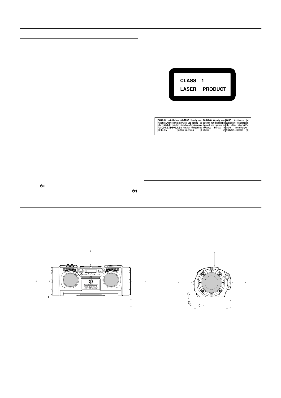
Caution: Proper Ventilation
To avoid risk of electric shock and fire, and to prevent damage, locate the apparatus as follows:
1 Front: No obstructions and open spacing.
2 Sides/ Top/ Back: No obstructions should be placed in the areas shown by the dimensions below.
3 Bottom: Place on the level surface. Maintain an adequate air path for ventilation by placing on a stand with a height of 10 cm or
more.
Front view
15 cm
15 cm
SUPER WOOFER
VOLUME
PRESET
ONE TOUCH
MID
/
TUNING
REC
TREBLE
STANDBY
STANDBY/ON
CD TAPE AUX
OPEN
VOLUME
MID
TREBLE
/
BAND
MULTI CONTROL
TUNER
REW STOP FF
15 cm
10 cm
Side view
15 cm
15 cm
15 cm
10 cm
CAUTION
1. Do not block the ventilation openings or holes.
(If the ventilation openings or holes are blocked by a
newspaper or cloth, etc., the heat may not be able
to get out.)
2. Do not place any naked flame sources, such as
lighted candles, on the apparatus.
3. When discarding batteries, environmental problems must be considered and local rules or laws
governing the disposal of these batteries must be
followed strictly.
4. Do not use this apparatus in a bathroom or places
with water. Also do not place any containers filled
with water or liquids (such as cosmetics or medicines, flower vases, potted plants, cups, etc.) on top
of this apparatus.
G-1
Page 3

SAFETY INSTRUCTIONS
“SOME DOS AND DON’TS ON THE SAFE USE OF EQUIPMENT”
This equipment has been disigned and manufactured to meet international safety standards but, like any electrical equipment,
care must be taken if you are to obtain the best results and safety is to be assured.
✮✮✮✮✮✮✮✮✮✮✮✮✮✮✮✮✮✮✮✮✮✮✮✮✮✮✮✮✮✮✮✮✮✮✮✮✮✮✮✮✮✮✮✮✮✮✮
Do read the operating instructions before you attempt to use the equipment.
Do ensure that all electrical connections (including the mains plug, extension leads and interconnections between pieces of
equipment) are properly made and in accordance with the manufacturer’s instr uctions. Switch off and withdraw the mains plug
when making or changing connections.
Do consult your dealer if you are ever in doubt about the installation, operation or safety of your equipment.
Do be careful with glass panels or doors on equipment.
✮✮✮✮✮✮✮✮✮✮✮✮✮✮✮✮✮✮✮✮✮✮✮✮✮✮✮✮✮✮✮✮✮✮✮✮✮✮✮✮✮✮✮✮✮✮✮
DON’T continue to operate the equipment if you are in any doubt about it working normally, or if it is damaged in any way–switch
off, withdraw the mains plug and consult your dealer.
DON’T remove any fixed cover as this may expose dangerous voltages.
DON’T leave equipment switched on when it is unattended unless it is specifically stated that it is designed for unattended opera-
tion or has a standby mode.
Switch off using the switch on the equipment and make sure that your family know how to do this.
Special arrangements may need to be made for infirm or handicapped people.
DON’T use equipment such as personal stereos or radios so that you are distracted from the requirements of traffic safety. It is
illegal to watch television whilst driving.
DON’T listen to headphones at high volume as such use can permanently damage your hearing.
DON’T obstruct the ventilation of the equipment, for example with curtains or soft furnishings.
Overheating will cause damage and shorten the life of the equipment.
DON’T use makeshift stands and NEVER fix legs with wood screws — to ensure complete safety always fit the manufacturer’s
approved stand or legs with the fixings provided according to the instructions.
DON’T allow electrical equipment to be exposed to rain or moisture.
ABOVE ALL
— NEVER let anyone, especially children, push anything into holes, slots or any other opening in the case -this could result
in a fatal electrical shock.;
— NEVER guess or take chances with electrical equipment of any kind
— it is better to be safe than sorry!
G-2
Page 4

Thank you for purchasing the JVC Powered Woofer CD System.
We hope it will be a valued addition to your home as well as your outdoor life, giving you years of enjoyment.
Be sure to read this instruction manual carefully before operating your new stereo system.
In it you will find all the information you need to set up and use the system.
If you have a query that is not answered by the manual, please contact your dealer.
Features
Here are some of the things that make your System both powerful and simple to use.
■ The controls and operations have been redesigned to make them very easy to use, freeing you to just enjoy the music.
• With JVC's COMPU PLAY you can turn on the System and automatically start the Radio, CD Player, or Casette
Deck with a single touch. (Only when AC power is used.)
■ The System is equipped with 16-cm dia. super woofers that provide powerful bass.
■ A 45-station preset capability (30 FM and 15 AM (MW/LW) in addition to auto-seek and manual tuning.
■ CD options include CD pitch control function, repeat, random and program play.
■ Auto-reverse tape function
■ Rhythm Machine provides various rhythm patterns, scratch sounds, and drum pad patterns.
■ Timer functions; set the system to automatically come on, switch off.
How This Manual Is Organized
• Basic information that is the same for many different functions - e.g. setting the volume - is given in the section ‘Basic Operations', and
not repeated under each function.
• The names of buttons/controls and display messages are written in all capital letters: e.g. TUNER BAND, "NO DISC".
• System functions are written with an initial capital letter only: e.g. Normal Play.
Use the table of contents to look up specific information you require.
We've enjoyed making this manual for you, and hope it serves you in enjoying the many features built into your System.
IMPORTANT CAUTIONS
1. Where to place the System
■
• Select a place which is level, dry and neither too hot nor too cold. (Between 0°C and 40°C.)
• Leave sufficient distance between the System and a TV.
• Do not use the System in a place subject to vibrations.
2. Power cord
■
• Do not handle the power cord with wet hands!
• Some power is always consumed as long as the power cord is connected to the wall outlet.
• When unplugging the System from the wall outlet, always pull the plug, not the power cord.
3. When carrying the System
■
• Remove a CD from the System.
• Disconnect all the cords from the System.
4.Malfunctions, etc.
■
• There are no user serviceable parts inside. In case of system failure, unplug the power cord and consult your dealer.
• Do not insert any metallic object into the System.
■■
Table of Contents
Features................................................................................1
How This Manual Is Organized...........................................1
IMPORTANT CAUTIONS.................................................1
Getting Started ..........................................................2
Basic Operations.......................................................6
Using the Tuner..................................... .... ................8
Using the CD Player........................................... .... . 10
Using the Cassette Deck ........................................ 1 3
Using the Cassette Deck ........................................ 1 4
1
Using the Rhythm Machine................................... 16
Listening to an Auxiliary Equipment.................... 21
Using the Microphone/Guitar................................ 22
Using the Timers.................................................... 23
Care And Maintenance .......................................... 25
Troubleshooting..................................................... 26
Specifications......................................................... 27
Page 5
■■
CLOCK
DOWN
UP
SET
TIMER
TIMER
ON/OFF
SLEEP
PROGRAM
RANDOM
REPEAT
DISPLAY
VOLUME
SUPER WOOFER
VOLUME
RM-SRVDP100
REMOTE CONTROL
AUX CD TAPE
BAND
FM MODE
TUNER
AUTO
PRESET
REVERSE MODE
REW
MULTI CONTROL
FF
MID /
TREBLE
Getting Started
Accessories
Check that you have all of the following items, which are supplied with the System.
Power Cord (1)
Remote Control (1)
Batteries (2)
Shoulder Strap (1)
If any of these items are missing, contact your dealer immediately.
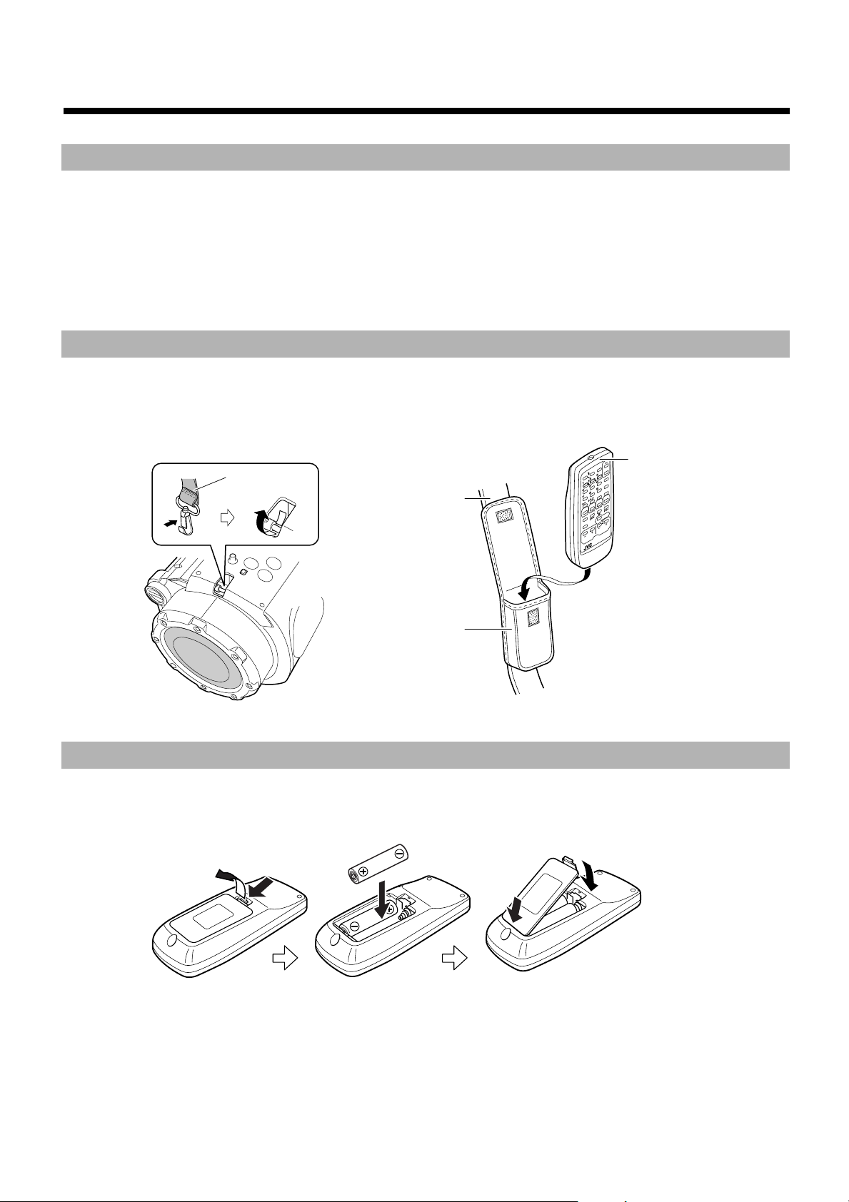
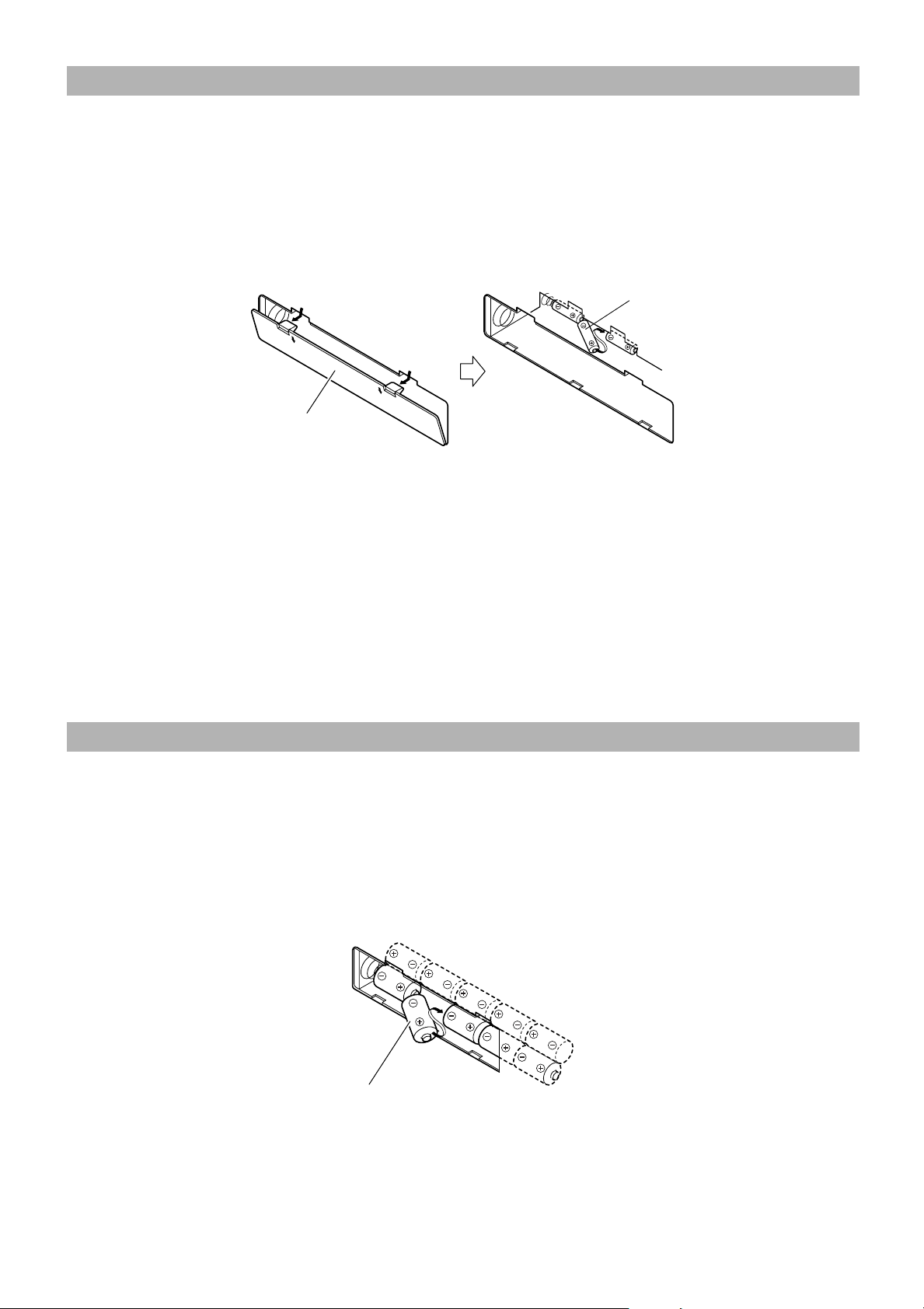
How To Carry the System
To carry the System, attach the supplied shoulder strap to each end of the System.
Press in the metal fitting of the shoulder strap and hook it over the shaft at each end of the System as shown in the figure.
To detach the shoulder strap, press in the metal fitting and unhook it from the shaft.
The shoulder strap is adjustable in length and has the remote control case.
Remote control unit
Shoulder strap
Shoulder strap
Remote control case
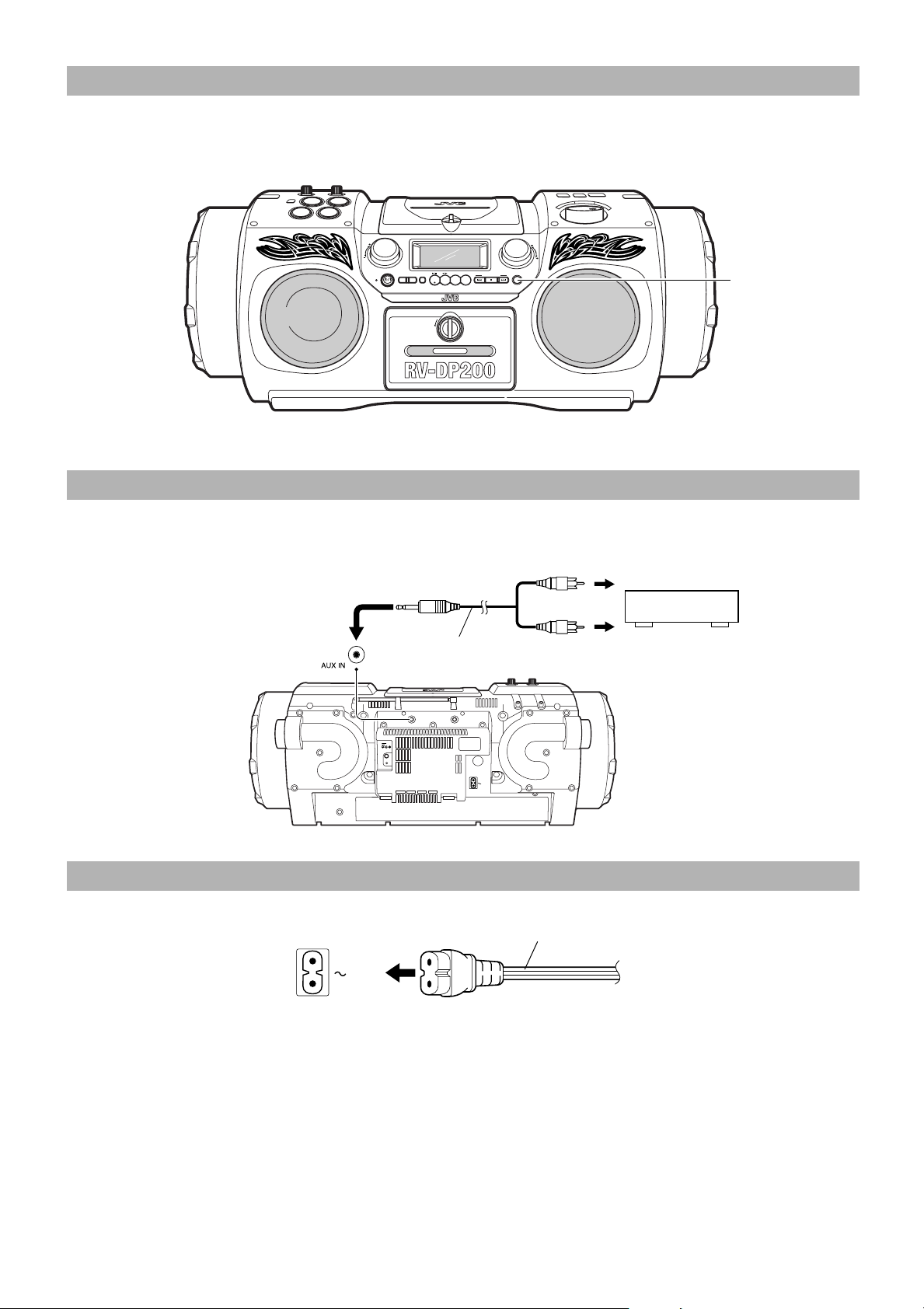
How To Put Batteries In the Remote Control
Match the polarity (+ and –) on the batteries with the + and – markings in the battery compartment.
R6P(SUM-3)/AA(15F)
2
1
CAUTION: Handle batteries properly.
To avoid battery leakage or explosion:
• Remove batteries when the Remote Control will not be used for a long time.
• When you need to replace the batteries, replace both batteries at the same time with new ones.
• Don't use an old battery with a new one.
• Don't use different types of batteries together.
1
2
2
Page 6
Using the Remote Control
Remote sensor
The Remote Control makes it easy to use many of the functions of the System from a distance of up to 7m (23 feet) away.
You need to point the Remote Control at the remote sensor on the System's front panel.
Note: If you point the Remote Control from the slant direction, the above distance will be shortened.
SUPER WOOFER
VOLUME
PRESET
TUNING
STANDBY
BAND
ONE TOUCH
MID
/
REC
TREBLE
CD TAPE AUX
TUNER
REW STOP FF
OPEN
MULTI CONTROL
VOLUME
MID
TREBLE
/
CAUTION: Make all connections before plugging the System into an AC power outlet.
Connecting Auxiliary Equipment
Connect a signal cord (not supplied) between the AUX IN terminal on the System and the output terminals of your auxiliary equipment (e.g.
turntable or MD player). You can listen to this source.
Stereo mini plug
Signal cord
(not supplied)
Pin-plug x 2
Turntable (with built-in equalizer) or
MD player (not supplied)
AUX IN
12V
DC IN
PHONES
AC IN
Connecting the AC Power Cord
Firmly insert the supplied AC power cord into the AC inlet on the back of the System.
Power cord
AC IN
CAUTIONS:
• ONLY USE THE JVC POWER CORD PROVIDED WITH THIS SYSTEM TO AVOID MALFUNCTION OR DAMAGE TO THE SYSTEM.
• BE SURE TO UNPLUG THE POWER CORD FROM THE OUTLET WHEN GOING OUT OR WHEN THE SYSTEM IS NOT IN USE FOR AN EXTENDED PERIOD OF TIME.
Now you can plug the AC power cord into the wall outlet, and your System is at your command!!
3
Page 7
Memory Backup Batteries
It is recommended that memory backup batteries are loaded in the System to prevent the contents of the memory from being erased when a
power failure occurs.
1. Open the battery cover on the back of the System by pulling it toward you while pressing the
■
tabs as shown by the arrows.
2. Load three batteries (not supplied) in the battery compartment in the order of "1" to "3".
■
• Be careful to put the batteries with the "+" and "–" terminals positioned correctly.
3. Securely close the battery cover.
■
To remove the batteries, remove the battery "3" first.
2
3
Battery cover
Notes:
• The memory backup batteries will not be consumed as long as the power is supplied from an AC outlet, loaded 10 batteries, or car battery
(DC12V). However, if no power is supplied to the System, the memory backup batteries should be replaced with new ones approximately
every 12 months to securely maintain the contents of the memory.
• Before replacing the memory backup batteries, always connect the AC power cord to the System to prevent the contents of memory from
being erased.
• When a power failure occurs, the time indication disappears from the display to save the battery power of the memory backup batteries.
CAUTION: Handle batteries properly.
To avoid battery leakage or explosion:
• When you need to replace the batteries, replace all batteries at the same time with new ones. Before replacing, you need to supply AC power
to the System.
• Don't use an old battery with new ones.
• Don't use different types of batteries together.
"R6P (SUM-3) / AA (15F)" size batteries
1
How To Operate the System on Batteries
You can operate the System on 10 batteries.
1 Open the battery cover on the back of the System by pulling it toward you while pressing the
■
tabs as shown by the arrows.
2. Put 10 batteries (not supplied) in the battery compartment in the order of "1" to "10" as shown.
■
• Be careful to put the batteries with the "+" and "-" terminals positioned correctly.
3. Securely close the battery cover.
■
To remove the batteries, remove the battery "10" first.
4
9
"R20/D (13F)" size batteries
Notes:
• When you operate the System on mains (AC) power or on car battery (DC12V), the power source auto matically switches from batteries to
AC or DC12V. However, you should remove the 10 batteries when operating on AC power or car battery (DC12V).
• When the batteries are exhausted, mistracking will occur during CD playback or sound will be distorted in termittently during tape playback.
You need to replace the batteries at a time.
• It is recommended that the AC power cord be used when recording important material or listening to a CD.
5
10
3
2
8
1
7
6
4
Page 8
CAUTION: Handle batteries properly.
To avoid battery leakage or explosion:
• Remove 10 batteries when the System will not be used for a long time.
• When you need to replace the batteries, replace all batteries at the same time with new ones.
• Don't use an old battery with new ones.
• Don't use different types of batteries together.
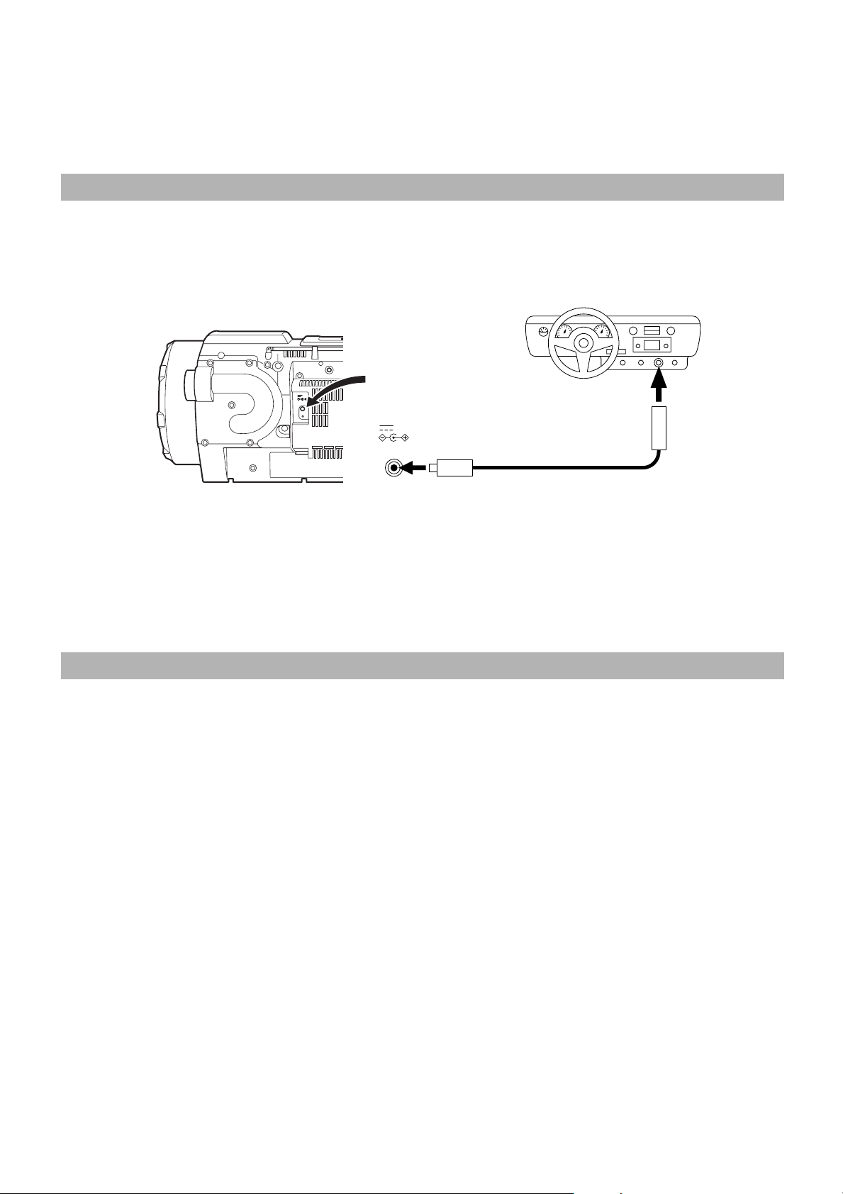
How To Operate the System on Car Battery (DC12V)
You can operate the Unit on car battery (DC12V).
1 First, connect the car adapter to the DC IN 12V jack on the back of the System, to avoid a
■
short-circuit of the car adapter.
2. Next, connect the car adapter to the cigarette lighter socket (DC12V) of the car.
■
AUX IN
12V
DC IN
PHONES
DC IN
12V
To car's cigarette lighter socket (DC12V)
AC IN
1
Optional exclusive car adapter (JVC model CA-R120E)
2
CAUTION: Use the System in a car properly.
• Be sure to use the specified car adapter (JVC model CA-R120E) to prevent mishaps or damage resulting from different polarity design.
• Unplug the AC power cord from the System when using the System with a car adapter.
• For safety, stop the car before performing operations.
• Be sure to start the engine when you use the car adapter, otherwise the car battery will be exhausted.
• During transport, stabilize the System in a box, etc.
• The Unit is not waterproof or dustproof. To prevent malfunctions, do not leave the System in a car for a long time.
COMPU PLAY
JVC's COMPU PLAY feature lets you control the most frequently used System functions with a single touch.
With One Touch Operation you can play a CD, a tape, or turn on the radio with a single press of the play button for that function. One Touch
Operation turns the power on for you, then starts the function you have specified. If the System is not ready (no CD in place, for example), the
System still powers on so you can insert a CD.
How One Touch Operation works in each case is explained in the section dealing with that function.
The COMPU PLAY buttons are:
On the Unit
CD 6 button
23
TAPE
TUNER BAND button
AUX button
On the Remote Control
CD 6 button
23
TAPE
TUNER BAND button
AUX button
Note: The COMPU PLAY feature is ineffective when the System is operated on batteries or car battery (DC12V).
5
Page 9
■■
DISPLAY
WOOFER
VOLUME+,–
Basic Operations
TIMER
CLOCK
TIMER
SUPER
DOWN
AUX CD TAPE
REVERSE MODE
REW
DISPLAY
SUPER WOOFER
VOLUME
ON/OFF
UP SET
AUTO
PRESET
MULTI CONTROL
VOLUME
RM-SRVDP100E
REMOTE CONTROL
SLEEP
PROGRAM
RANDOM
REPEAT
TUNER
BAND
FM MODE
MID /
TREBLE
FF
%
MID/
TREBLE
VOLUME+,–
SUPER
WOOFER
VOLUME+,–
STANDBY indicator
%
Turning the Power On and Off
Note: The lighting condition for the "STANDBY" indicator and
the display differs depending on the power source being
used, as follows:
Power source "STANDBY" indicator/Display
• The "STANDBY" indicator lights when
AC power
Batteries or car
battery (DC12V)
power is turned off.
• Backlighting of the display is illuminated
when power is turned on.
• The "STANDBY" indicator does not light.
• Backlighting of the display is not
illuminated.
PHONES
AUX IN
12V
DC IN
SUPER WOOFER
VOLUME
BAND
PRESET
ONE TOUCH
MID
/
TUNING
REC
TREBLE
STANDBY
CD TAPE AUX
TUNER
OPEN
MULTI CONTROL
REW STOP FF
VOLUME
MID
TREBLE
/
VOLUME +, –
MID/TREBLE
LEVEL indicator
PHONES
AC IN
■ Some power is always consumed even though power is turned
off (called Standby Mode).
■ To switch off the System completely, unplug the AC power
cord from the AC outlet. When you unplug the AC power cord,
the clock will be reset to "0:00" when no memory backup batteries are installed.
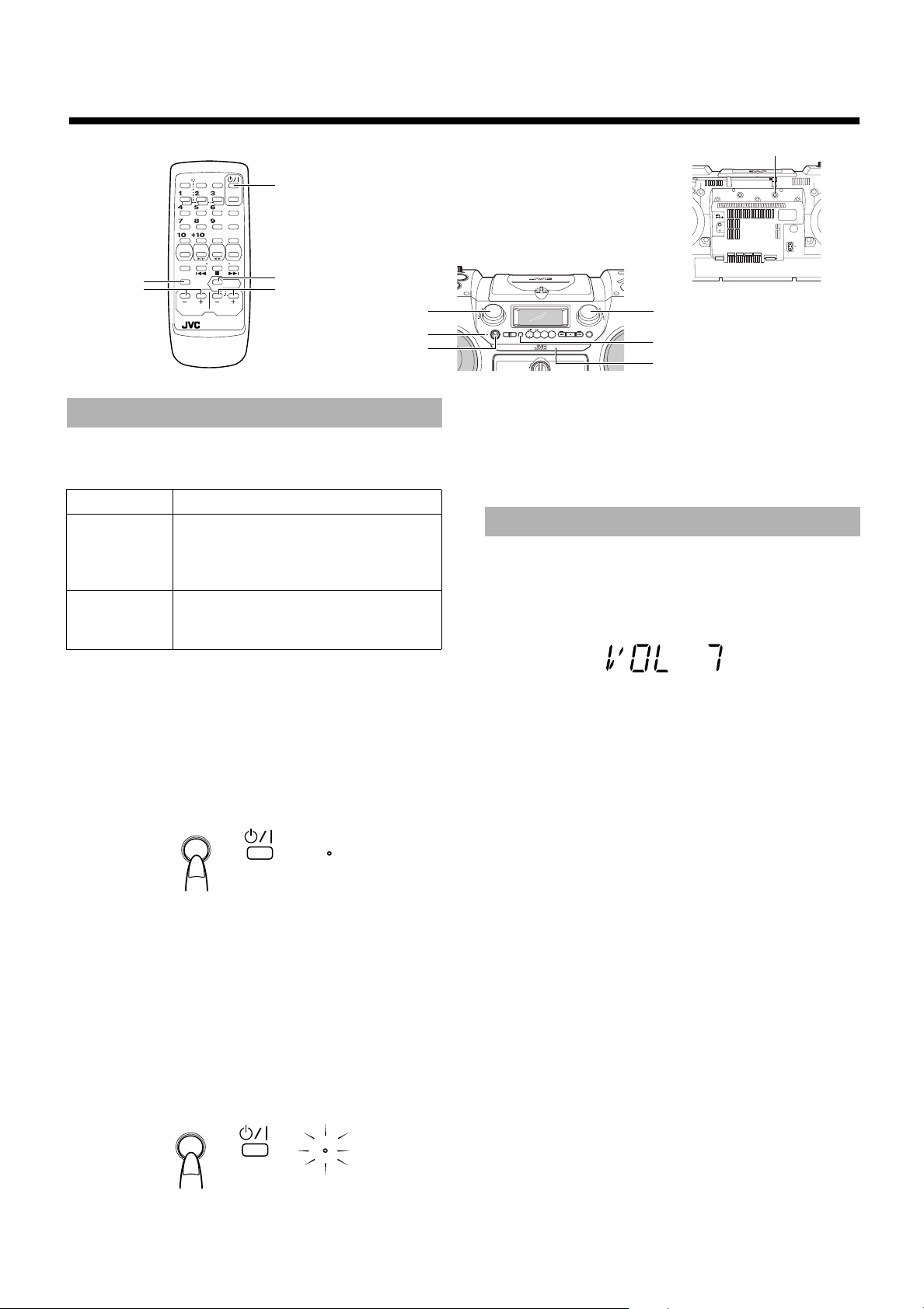
Adjusting the Volume
You can adjust the volume level between 0 and 50.
Using the Unit ————————————
Turn the VOLUME control clockwise to increase the volume or
turn it counterclockwise to decrease the volume.
Turning the System On ——————
Press the
• When the System is operated on batteries or car battery
(DC12V), press the % button on the Unit.
The "STANDBY" indicator goes out when the System is operated
on AC power.
The display comes on and the System is ready to continue in the
mode it was in when the power was last turned off.
%%%%
button.
%
or
STANDBY
■ For example, if the last thing you were doing was listening to a
CD, you are now ready to listen to a CD again. If you wish, you
can change to another source.
■ If you were listening to the Tuner last, the Tuner comes on play-
ing the station it was last set to.
Turning the System Off ——————
Press the
The "STANDBY" indicator lights up when the System is operated
on AC power.
The contents of the display changes to the clock, and "CLOCK" indicator and the time are displayed without backlighting.
%%%%
button.
Using the Remote Control —————
Press the VOLUME + button to increase the volume or press the
VOLUME – button to decrease it.
When you keep pressed the VOLUME + or – button, the volume
changes rapidly.
CAUTION: DO NOT start playing any source without first setting the volume to minimum, as a sudden blast of sound can damage your hearing,
speakers and/or headphones.
For private listening
Connect a pair of headphones to the PHONES jack. No sound
comes out of the speakers.
Be sure to turn down the volume before connecting or putting on
headphones.
LEVEL indicator
When one of sources is played, the LEVEL indicator on the Unit will
light in green, orange, or red according to the signal leve l. (Four LEDs
are arranged respectively on both sides of the LEVEL indicator.)
• The lighting condition of the LEVEL indicator is not affected
by the volume setting.
%
or
STANDBY
6
Page 10
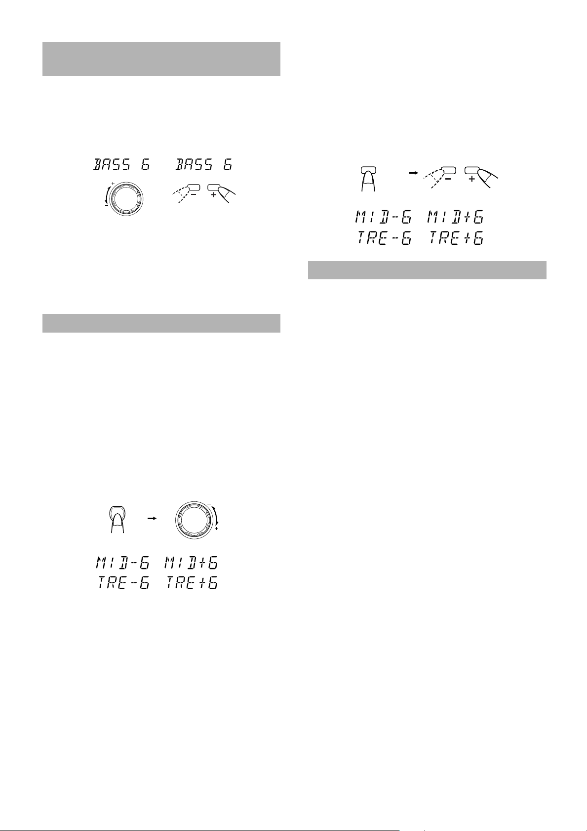
Adjusting the Super Woofer
(Within 5 seconds)
Volume
You can adjust the bass level between BASS 1 (minimum) and
BASS 6 (maximum). You can use this effect only for playback.
Using the Unit ———————————
Turn the SUPER WOOFER VOLUME control clockwise to increase the bass level or turn it counterclockwise to decrease the bass
level.
SUPER WOOFER
VOLUME
or
Using the Remote Control —————
Press the SUPER WOOFER VOLUME + button to increase the
bass level or press the SUPER WOOFER VOLUME – button to decrease it.
SUPER WOOFER
VOLUME
Using the Remote Control —————
1. Press the MID/TREBLE button to select MID
■
or TREBLE.
Each time you press the button, the display changes as follows:
MID=TREBLE=Currect sound source=(back to the
beginning)
2. Press the VOLUME + or VOLUME – button
■
within five seconds to adjust the mid or treble level.
MID /
TREBLE
VOLUME
Showing the Time (DISPLAY)
Note: This function is not effective when the headphones are in
use.
Tone Control (MID/TREBLE)
You can control the tone by changing the mid and the treble between –6 and +6. (0: Flat)
Using the Unit ———————————
1. Press the MID/TREBLE button to select MID
■
or TREBLE.
Each time you press the button, the display changes as follows:
MID=TREBLE=Currect sound source=(back to the
beginning)
2. Turn the VOLUME control clockwise or
■
counterclockwise within five seconds to
adjust the mid/treble level.
MID
/
TREBLE
(Within 5 seconds)
VOLUME
MID / TREBLE
In Standby mode, the backlight of the display goes out, and the
"CLOCK" indicator and the current time (clock) appear on the display.
While the power is turned on, you can see the current time (clock)
at any time, as follows:
Press the DISPLAY button on the Remote Control. Each time you
press the button, the display changes as follows:
Current sound source (e.g. FM103.50 MHz)=Clock=(back to the
beginning)
Note: To let work the clock, you need to set the clock first. (See
"Setting the Clock" on page 23.)
7
Page 11
■■
CLOCK
DOWN
UP SET
TIMER
TIMER
ON/OFF
SLEEP
PROGRAM
RANDOM
REPEAT
DISPLAY
VOLUME
SUPER WOOFER
VOLUME
RM-SRVDP100E
REMOTE CONTROL
AUX CD TAPE
BAND
FM MODE
TUNER
AUTO
PRESET
REVERSE MODE
REW
MULTI CONTROL
FF
MID /
TREBLE
For FM
For AM (MW/LW)
Using the Tuner
4
¢
Number
Keys
4
AUTO PRESET
TUNER BAND
¢
SUPER WOOFER
VOLUME
STANDBY
PRESET
ONE TOUCH
MID
/
TUNING
REC
TREBLE
CD TAPE%AUX
STANDBY/ON
OPEN
PRESET TUNING
When the System is in use, the display shows other items as well.
For simplicity, we show here only the items described in this section.
You can listen to FM and AM (MW/LW) stations. Stations can be
tuned in manually, automatically, or from preset memory storage.
■ Before listening to the radio:
• Fully extend the FM telescopic antenna.
One Touch Radio —————————
• This operation is effective only when the System is operated on
AC power.
Just press the TUNER BAND button to turn on the System and start
playing the station you were last tuned to.
■
You can switch from any other sound source to the radio by
pressing the TUNER BAND button.
Tuning In a Station
1. Press the TUNER BAND button.
■
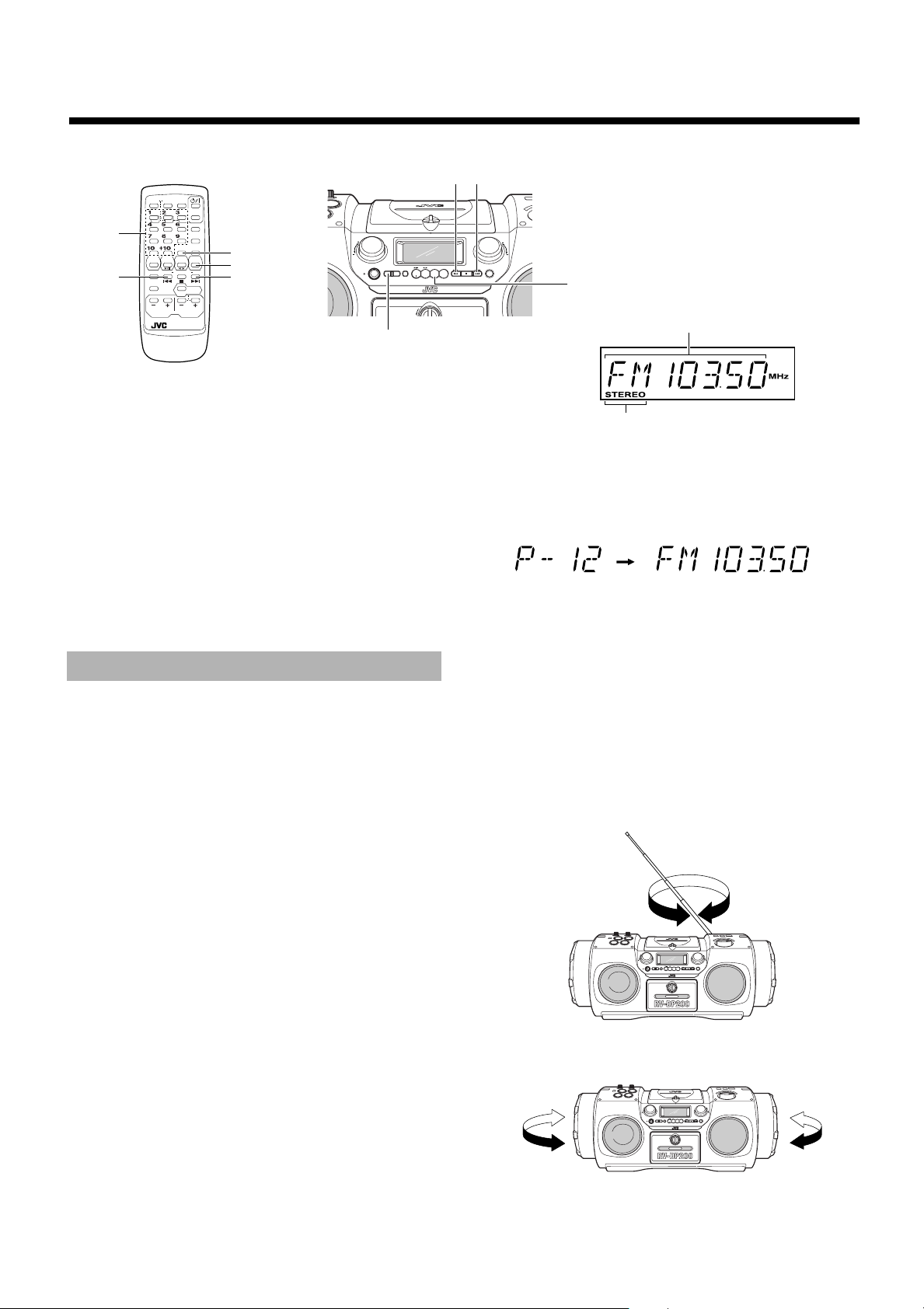
The Band and Frequency you were last tuned to appear on the
display.
Each time you press the button, the band and FM mode change
as follows:
FM=FM-MONO=AM=(back to the beginning)
• In FM mode, when you tune in an FM broadcast and the
"STEREO" indicator lights up, you can hear stereo effects.
If an FM stereo broadcast is hard to receive or noisy, select
FM-MONO mode. The "STEREO" indicator will go out.
Reception improves, but you lose any stereo effect.
VOLUME
MID
TREBLE
/
BAND
MULTI CONTROL
TUNER
REW STOP FF
TUNER BAND
Band, Frequency, Preset channel
STEREO indicator
■
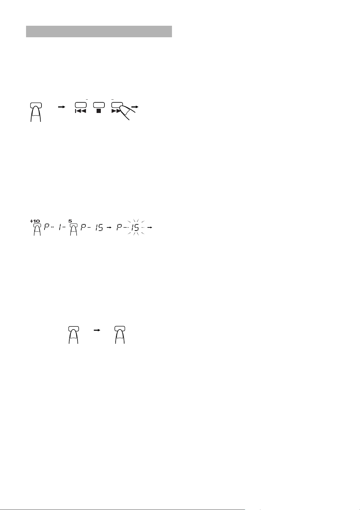
Preset Tuning (Possible only after presetting
stations)
Select the desired preset number (displayed as "P-XX" on the
display) using the PRESET TUNING button on the Unit or the
number keys on the Remote control. After 1 second, the display
will show the preset number's band and frequency.
(After 1 second)
PRESET TUNING button:Each time you press the button,
the preset number increases.
Number keys: To select P-5, press 5.
To select P-15, press +10 then 5.
To select P-20, press +10 once
then press 10.
3. Turn the FM antenna for the best reception.
■
For an AM (MW/LW) broadcast, turn the Unit to obtain the best
reception. Placing the Unit near the window, for example, will
improve AM reception.
2. Select a station using one of the following
■
methods.
■
Manual Tuning
Press the
4
or ¢ button repeatedly to move from frequency
to frequency until you find the station you want.
OR
■
Auto Tuning
If you press and hold the
4
or ¢ button for one second or
more, the frequency changes down, or up, automatically until a
station is found.
OR
SUPER WOOFER
VOLUME
PRESET
TUNING
STANDBY
SUPER WOOFER
VOLUME
STANDBY
VOLUME
TREBLE
/
BAND
ONE TOUCH
MID
/
MULTI CONTROL
REC
TREBLE
CD TAPE AUX
TUNER
REW STOP FF
OPEN
VOLUME
MID
TREBLE
/
BAND
PRESET
ONE TOUCH
MID
/
MULTI CONTROL
TUNING
REC
TREBLE
CD TAPE AUX
TUNER
REW STOP FF
OPEN
8
Page 12
Presetting Stations
You can preset up to 30 FM stations and up to 15 AM (MW/LW)
stations.
Note: Preset numbers may have been set to factory test frequen-
cies prior to shipment. This is not a malfunction. You can
preset the stations you want into memory by following one
of the presetting methods below:
Manual Presetting —————————
TUNER
BAND
FM MODE
1. Select a band (either AM or FM/FM-MODE)
■
by pressing the TUNER BAND button.
2. Press the 4 or ¢ button to tune in a sta-
■
tion.
3. Press the number key for more than two
■
seconds to store in memory for the desired
preset number.
The preset number blinks for four seconds and then the preset
station for the preset number appears.
Example: To preset the tuned station to the preset number 15,
REW
MULTI CONTROL
press +10 then 5 for more than two seconds. The
display changes as follows.
FF
Number key
(For 2 seconds)
(Tuned
station)
(For 2 seconds)
4. Repeat above steps 1 to 3 for each station
■
you want to store in memory with a preset
number.
To change the preset stations, repeat the same steps as
above to overwrite a new station.
Auto Presetting ——————————
In each band, you can automatically preset FM-30, AM(MW/LW)15 stations. Preset numbers will be allocated as stations are found,
starting from the lowest station and moving up the frequency.
TUNER
BAND
FM MODE
1. Select a band (either AM or FM/FM-MODE)
■
by pressing the TUNER BAND button.
2. Press one of the following buttons.
■
On the Unit:
Press the PRESET TUNING button for more than two seconds.
On the Remote Control:
Press the AUTO PRESET button on the Remote Control for
more than two seconds.
AUTO
PRESET
(For 2 seconds)
3. Repeat steps 1 and 2 for the other band.
■
If you want to change the preset stations, carry out the Manual
■
Presetting for the desired preset numbers.
CAUTION: To prevent the preset stations from being erased because of a power failure, etc., install
memory backup batteries in the System. (See
page 4.)
9
Page 13
■■
CLOCK
DOWN
UP SET
TIMER
TIMER
ON/OFF
SLEEP
PROGRAM
RANDOM
REPEAT
DISPLAY
VOLUME
SUPER WOOFER
VOLUME
RM-SRVDP100E
REMOTE CONTROL
AUX CD TAPE
BAND
FM MODE
TUNER
AUTO
PRESET
REVERSE MODE
REW
MULTI CONTROL
FF
MID /
TREBLE
Track number
Playback time
Total track number Total playback time
Using the CD Player
7
4
¢
Jog dial
Number
Keys
6
CD
4
PROGRAM
RANDOM
REPEAT
7
¢
CD
6
SUPER WOOFER
VOLUME
STANDBY
When the System is in use, the display shows other items as well.
For simplicity, we show here only the items described in this section.
You can use Normal, Random, Program or Repeat Play. Repeat
Play can repeat all the tracks or just one of the tracks on the CD.
Here are the basic things you need to know to play a CD and locate
the different tracks on it.
The Quickest Way To Start a CD Is With the
One Touch Operation (effective only when
the System is operated on AC power)
■ Press the CD6 button.
• The power is automatically turned on. If a CD is already
inserted, it will start playing from the first track.
• If no CD is inserted, "NO DISC" appears on the display and the
CD Player remains in Stop mode.
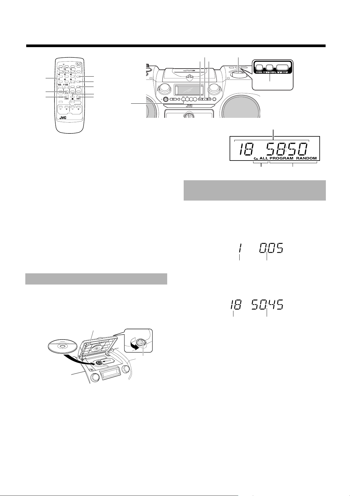
Setting a CD
1. Turn the CD cover knob counterclockwise
■
to open the CD cover.
2. Place a CD, with its label side up as shown
■
below.
CD cover
Knob
VOLUME
MID
TREBLE
/
PRESET
TUNING
BAND
ONE TOUCH
MID
REC
/
TREBLE
CD TAPE AUX
OPEN
MULTI CONTROL
TUNER
REW STOP FF
CD PITCH CONTROL
Track number, Playing
time, Preset number
Repeat
indicator
Play mode indicator
Basics of Using the
CD Player-Normal Play
To Play a CD—————————————
1. Set a CD.
■
2. Press the CD6 button.
■
The first track of the CD begins playing.
• The CD Player automatically stops when the last track of the
CD has finished playing.
To stop playing the CD, press the
The following information for the CD is displayed.
To pause, press the CD
6
the display.
To cancel pause, press the same button again. Play continues
from the point where it was paused.
Note: Do not open the CD cover during playback.
7
button.
button. The playback time blinks on
3. Close the CD cover until it clicks.
■
To remove the CD, open the CD cover in Stop mode.
■ You can place an 8 cm (3'') CD without an adaptor.
■ If the CD cannot be read correctly (because it is scratched, for
example), " 0 0:00" appears on the display.
■ You can place a CD while listening to the other source.
Locating a Track with Remote Control Directly —————————————
During playback or in Stop mode, press the number keys on the Remote Control to directly play a track.
To directly play the track 5, press 5.
To directly play the track 15, press +10 then 5.
To directly play the track 20, press +10 once then press 10.
10
Page 14
To Select a Track —————————
During playback, press the 4 or ¢ button to select the track you
want.
The selected track starts playing.
•Press the
track.
•Press the
played. Press the 4 button twice quickly to skip to the beginning of the previous track.
You can also select a track in Stop mode with the same buttons.
When the button is pressed, the selected track and its playback time
appear on the display. To play the CD after selecting a track, just
press the CD 6 button.
¢ button once to skip to the beginning of the next
4 button to skip to the beginning of the track being
Search Play ————————————
Holding down the 4 or ¢ button, during playback, will fast for ward/backwards the CD so you can quickly find a particular passage in the track you are listening to. During Search Play, you can
hear the sound of approx. one forth level.
Programming the
Playing Order of the Tracks
You can program the playing order of the tracks using the Remote Control.
■ You can program up to 20 tracks in any desired order including
the same tracks.
■ You can only make a program when the CD Player is stopped.
1. Set a CD.
■
2. Press the CD6 button.
■
3. Press the 7 button to stop the CD.
■
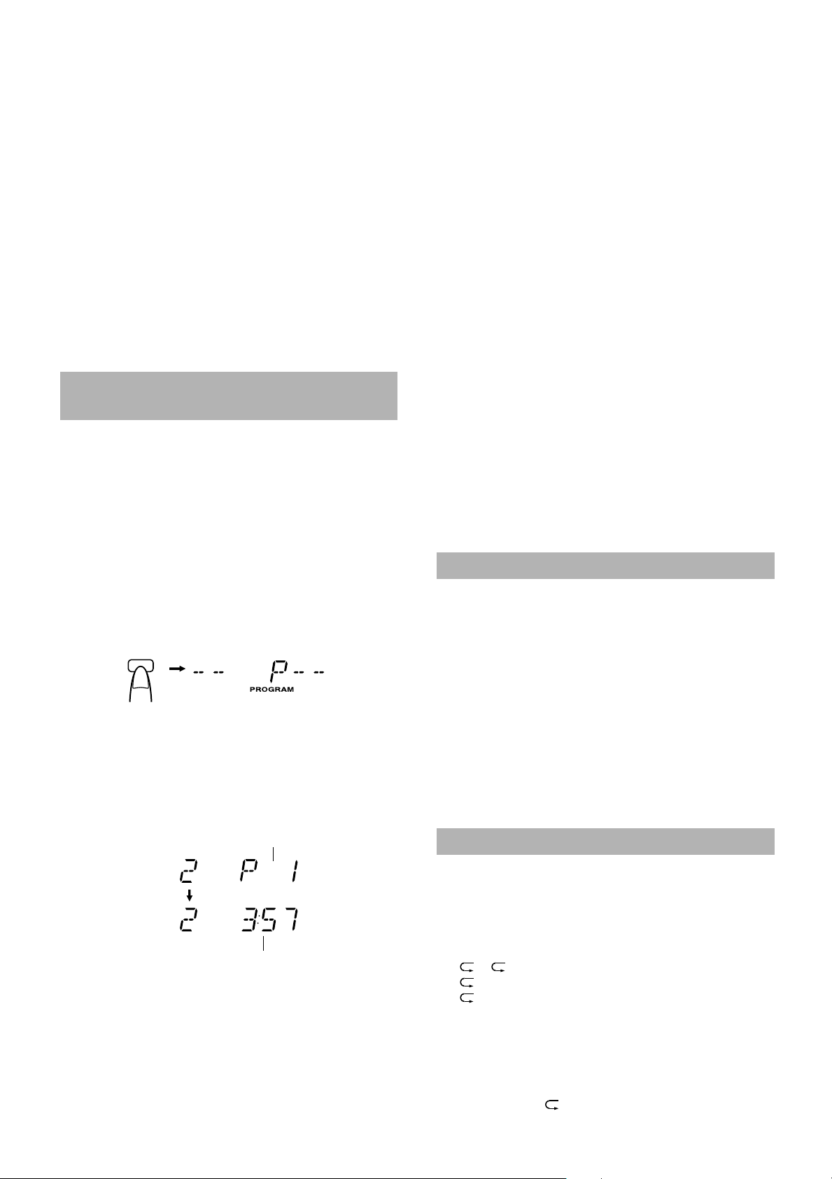
4. Press the PROGRAM button.
■
The System enters the programming mode and the
"PROGRAM" indicator lights up.
PROGRAM
7. Press the CD 6 button.
■
The System plays the tracks in the order you have programmed
them.
■ You can skip to a particular program track by pressing the 4
or ¢ button during Program Play.
To confirm the programmed tracks while the CD player is
stopped, press the
program will successively be displayed in the programmed order.
To delete all the tracks in the program, press the 7 button repeatedly until all the tracks are cleared. Turning off the power will
also clear the programmed tracks.
To exit Program mode, while the CD Player is stopped, press
the PROGRAM button to turn off the "PROGRAM" indicator. To
restore Program mode, in Stop mode, press the same button to light
on the "PROGRAM" indicator.
Notes:
• If the total playback time of the programmed tracks exceeds 99
minutes 59 seconds, the total playback time will go out on the
display.
• When the CD contains more than 21 tracks:
When you try to program a track number exceeding 20 (for
example the 25th track), the total playback time indication will
go out, though programming is possible.
4 or ¢ button; the tracks making up the
To Modify the Program ———————
Modify the contents of the program while the CD Player is stopped.
Each time you press the 7 button, the last track in the program is deleted. To add new tracks to the end of the program, repeat above
steps 5 and 6.
Random Play
The tracks will play in no special order when you use this mode.
1. Press the RANDOM button on the Remote
■
Control.
The "RANDOM" indicator lights up on the display.
5. Press the number keys to select the track
■
to program.
To select the track 5, press 5.
To select the track 15, press +10 then 5.
To select the track 20, press +10 once then press 10.
Example: for track 2, press 2.
Program order number
(After 2 seconds)
Total playback time of the programmed tracks
6. Repeat step 5 to select the other tracks for
■
the program.
You can see the total playback time of the programmed tracks
on the display.
• To cancel the last track programmed, press the
once.
7 button
11
2. Press the CD6 button.
■
The tracks are played in random order once.
To skip a track during playback, press the ¢ button to jump
to the next track in the random sequence. Press the 4 button to
jump back to the start of a track being played.
To exit Random Play mode, press the RANDOM button to turn
off the "RANDOM" indicator after pressing the
CD Player, or turn off the power.
7 button to stop the
Repeating Tracks
You can repeat the tracks or individual track as many times as you
like.
Press the REPEAT button on the Remote Control.
The Repeat indicator changes with each press of the button, as
shown below.
= ALL =blank display = (back to the beginning)
: Repeats one track.
ALL : In Normal Play mode, repeats all the tracks.
In Program Play mode, repeats all the tracks in the
program.
In Random Play mode, repeats all the tracks in random order.
To exit Repeat mode, press the REPEAT button until the Repeat
indicator on the display goes out.
■ In Random Play, cannot be selected.
■ Repeat mode remains in effect even when you change the play
mode.
Page 15

CD Pitch Control
During playback a CD, you can change the playback pitch (playback speed) of the CD within ±12%.
CD PITCH CONTROL
1. During playback, press the CD PITCH CON-
■
TROL button on the Unit.
The current CD pitch will appear on the display for five seconds.
2. Within five seconds, turn the Jog dial to
■
increase or decrease the CD pitch.
Turning the Jog dial clockwise increases the pitch and turning it
counterclockwise decreases the pitch.
You can adjust the CD pitch between –12 and +12.
SPD +12: 112% speed
SPD ± 0: Normal speed (100%)
SPD –12: 88% speed
Note: The CD pitch returns to the original one (normal speed)
with the following operations:
• Other music source except the Rhythm Machine (for example,
Tuner) is selected.
• Power is turned off.
12
Page 16
■■
■■
Using the Cassette Deck
(Listening to a Tape)
TIMER
CLOCK
TIMER
ON/OFF
UP SET
PRESET
REW
MULTI CONTROL
RM-SRVDP100E
REMOTE CONTROL
PROGRAM
RANDOM
AUTO
REPEAT
MID /
TREBLE
VOLUME
SLEEP
TUNER
BAND
FM MODE
TAPE
2 3
FF
7
¢
TAPE
2 3
SUPER WOOFER
VOLUME
STANDBY
%
STANDBY/ON
4
REVERSE
MODE
DOWN
AUX CD TAPE
REVERSE MODE
DISPLAY
SUPER WOOFER
VOLUME
The Cassette Deck allows you to play and record audio tapes.
■ With Automatic Tape Detection, you can listen to type I, II or
IV tapes without having to change any settings.
The use of tapes longer than 120 minutes is not recommended,
since characteristic deterioration may occur and these tapes easily jam in the pinch-rollers and the capstans.
One Touch Play ——————————
This operation is effective only when the System is oper ated on AC
power.
button on the Unit or the Remote Con-
By pressing the TAPE
trol, the System will come on, "TAPE" appears on the display, and
if a tape is in the deck, it will start to play. If no tape is loaded, insert
a tape, or select other function.
2 3
Reverse mode indicator
7
¢
4
VOLUME
MID
TREBLE
/
BAND
PRESET
ONE TOUCH
MID
/
CD TAPE AUX
OPEN
MULTI CONTROL
TUNER
REW STOP FF
TUNING
REC
TREBLE
Reverse
Forward
To stop playing, press the ■ button.
To remove the tape, stop the tape, and open the cassette
holder by turning the cassette holder knob counterclockwise.
To Fast-Wind A Tape ————————
Press the ¢ or 4 button to fast-wind the tape. The Tape Direction indicator
• The Cassette Deck automatically stops when the tape reac hes its
end.
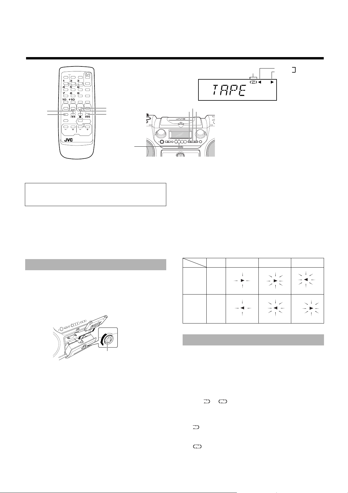
The following table shows the relationship between the Tape
Direction indicator and the actual tape travelling direction in
each mode. The tape travelling direction is indicated by the
blinking indicator.
[Tape Direction indicator and tape travelling direction in each mode]
3 or 2 will rapidly blink on the display.
Tape Direction indicator
Regular Play
When the power is already on, you can use this basic procedure:
1. Turn the cassette holder knob counter-
■
clockwise to open the cassette holder.
2. Put the cassette in, with the side you want
■
to listen facing toward you.
Knob
3. Close the holder gently until it clicks.
■
2 3
4. Press the TAPE
■
The tape is played in the direction shown by the Tape Direction
indicator. The Tape Direction indicator
verse) blinks slowly.
3
(Forward playback):
The side of the tape facing you is played back.
2
(Reverse playback):
The opposite side of the tape is played back.
5. If you need to change the playback direc-
■
tion, press the TAPE
The opposite side Tape Direction indicator lights up and the
tape playback direction changes.
button.
2 3
(Forward) or
3
button.
(Re-
2
Forward
Reverse
Stop Playback
3
(Slow)
2
(Slow) (Rapid)
¢
(Rapid)
FF
4
2
REW
3
(Rapid)
(Rapid)
*Blinking indicator shows the tape travelling direction.
Reverse Mode
You can set a tape to play just one side, both sides in succession, or
both sides continuously.
Press the REVERSE MODE button on the Remote Control.
The Reverse mode indicator changes with each press of the button as
shown.
== = (back to the beginning)
OOOO
: The Cassette Deck automatically stops after playing
OOOO
one side of the tape.
: The Cassette Deck automatically stops after playing
both sides of the tape. (Stops when playback in the
reverse (
: The Cassette Deck continues to play both sides of the
tape until the e button is pressed.
2) direction is finished.)
13
Page 17
■■
■■
CD
6
REVERSE
MODE
Using the Cassette Deck
(Recording)
7
TIMER
CLOCK
TIMER
ON/OFF
UP SET
PRESET
REW
MULTI CONTROL
REMOTE CONTROL
PROGRAM
RANDOM
AUTO
MID /
TREBLE
VOLUME
RM-SRVDP100E
SLEEP
REPEAT
TUNER
BAND
FM MODE
SUPER WOOFER
VOLUME
PRESET
TUNING
TAPE
FF
2 3
7
PRESET
TUNING
STANDBY
STANDBY/ON
%
ONE
TOUCH
REC
BAND
ONE TOUCH
MID
/
REC
TREBLE
CD TAPE AUX
TUNER
OPEN
TAPE
Reverse mode indicator
MULTI CONTROL
REW STOP FF
2 3
VOLUME
MID
/
DOWN
AUX CD TAPE
REVERSE MODE
DISPLAY
SUPER WOOFER
VOLUME
When the System is in use, the display shows other items as well.
For simplicity, we show here only the items described in this section.
TREBLE
REC indicator
Forward
Tape Direction
indicator
Reverse
Recording onto a tape from any of the sound sources is simple. Just
place a tape in the Cassette Deck, have the source ready, make one
or two settings, and you're ready to record. For each source the procedure is a little bit different so we explain each separately. But first,
here are a few things to make your recordings better.
Things To Know Before You Start
Recording —————————————
■ It should be noted that it may be unlawful to re-record
per-recorded tapes, records, or discs without the consent of the owner of copyright in the sound or video
recording, broadcast or cable programme and in any
literary, dramatic, musical, or artistic work embodied
therein.
■ When you want to record onto both sides of a tape, you can set
Reverse mode to do so. Recording automatically stops after recording in the reverse (
the tape direction is forward (
2) direction. Therefore, make sure that
3) when recording with Reverse
mode on.
■ The recording level, which is the volume at which the new tape
is being made, is automatically set correctly, so it is not affected
by the VOLUME control on the System. Nor is it affected by
adjusting the sound effects. Thus, during recording you can adjust the sound you are actually listening to without affecting the
recording level.
■ Two small tabs on the back of the cassette tape, one for side A
and one for side B, can be removed to prevent accidental erasure
or recording.
■ To record on a cassette with the tabs removed, you must cover
the holes with adhesive tape first. However, when a type II tape
is used, only cover part of the hole as shown, since the other part
of the hole (Type II detection slot) is used to detect the tape
type.
Type II detection
slot
Adhesive tape
■ Type I and Type II tapes can be used for recording.
CAUTION: If a recording you make has excessive
noise or static, the System may have been too
close to a TV which was on during the recording.
Either turn off the TV or increase the distance between the TV and the System.
Standard Recording
You can record any sound source to tape.
The sources are CD, Tuner, auxiliary equipment, Rhythm Machine,
microphone and guitar. The microphone sound and guitar sound can
be mixed with any source. Also, you can mix the sound from the
Rhythm Machine with the CD or auxiliary equipment.
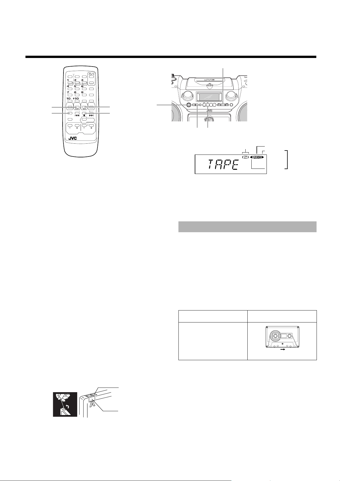
1. Insert a blank or erasable cassette tape
■
into the Cassette Deck.
Be sure that the Tape Direction indicator and the tape insertion
direction are as follows:
[Forward recording]
Tape Direction indicator Tape insertion direction
3
(Forward)
(Front view)
*Recording will be made on the tape side facing you.
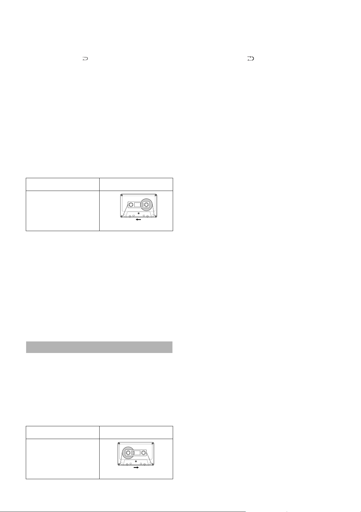
• If the Tape Direction indicator
TAPE 2 3 button to change the direction. (In this case, since
the tape is played, you need to press the ■ button. Then, press
4 button to rewind the tape. You may need to wind past
the
the leader tape which cannot be recorded onto.)
• If the inserted tape is not fully rewound, press the 4 button to
rewind it. You may need to wind past the leader tape which cannot be recorded onto.
2 (Reverse) is lit, press the
Note: At the start and end of cassette tapes, there is lea d er ta pe
which cannot be recorded onto. Thus, before recording, wind on the
leader tape first to ensure getting the beginning of the recording.
14
Page 18
2. If you want to record on both sides of the
■
tape, press the REVERSE MODE button on
the Remote Control to set the System in
Reverse mode.
Press the button until indicator is lit.
2. If you want to record on both sides of the
■
tape, press the REVERSE MODE button on
the Remote Control to set the System in
Reverse mode.
Press the button until indicator is lit.
3. Prepare the source, by, for example, tuning
■
in a radio station, playing the Rhythm
Machine, or turning on the connected auxiliary equipment.
Note: For CD recording, refer to "CD Direct Recording" de-
scribed below.
4. Press the ONE TOUCH REC button on the
■
Unit.
The "REC" indicator lights up and the System starts recording.
• If the tab of the cassette tape is removed to protect erasure
or recording, recording does not start.
TIP: When you want to record in the reverse direction, you should
set the Tape Direction indicator and the cassette tape as follows in step 1. Next, start from step 3.
[Reverse recording]
Tape Direction indicator Tape insertion direction
2
(Reverse)
(Front view)
*Recording will be made on the opposite side tape.
To stop at any time during the recording
process, press the ■ button.
Recording an AM station to tape
When recording an AM broadcast, beats may be produced which
are not heard when listening to the broadcast. If this happens, press
the PRESET TUNING button on the Unit to eliminate the beats.
1. Set to AM station and start recording.
2. Press the PRESET TUNING button to eliminate the beats.
Each time you press the button, the display changes as shown
below:
CUT-1= CUT-2 = CUT-3 = CUT-4 =(back to the begin-
ning)
CD Direct Recording
Everything on the CD goes onto the tape in the order it is on the CD,
or according to the order you have set in a program.
1. Insert a blank or erasable cassette tape
■
into the Cassette Deck.
Be sure that the Tape Direction indicator and the tape insertion
direction are as follows:
(For details, refer to step 1 in "Standard Recording" on
page 14.)
[Forward recording]
Tape Direction indicator Tape insertion direction
3
(Forward)
3. Set a CD.
■
4. Press the CD 6 button.
■
5. Press the 7 button.
■
• If you want to record specific tracks only, program the
tracks first. You can check their total playback time on the
display during programming. (See page 11.)
6. Choose whether to have pauses between
■
recorded selections.
• If nothing is done, a non-recorded pause of about four seconds will be automatically left between selections.
• If you do not want pauses between selections, do the following before proceeding to the next step.
Press the CD
7. Press the ONE TOUCH REC button on the
■
Unit.
The "REC" indicator lights up and the System starts recording.
• If you make a recording with Reverse mode on, the System
will record the last song at the end of the first side onto the
next side from its beginning when the song has been recorded more than 10 seconds on the first side.
If the last song has been recorded less than 10 seconds, then
the previous song will again be recorded on the next side as
it will not be completely recorded on the first side because
of leader tape.
• After the CD Player has played the entire CD, or all the programmed tracks, the tape automatically stops.
To stop at any time during the recording process, press the
e button. The tape stops after four seconds.
Notes:
• When making SLEEP timer settings while doing CD Direct
recording, set enough time to allow for the CD to finish playing, otherwise the power will go off before recording is completed.
• When the CD PITCH CONTROL is used for recording, note
that the recordable length of time varies according to the pitch
(speed).
Example:
Normal pitch:10 tracks can be recorded.
Slow pitch: Only 9 tracks can be recorded.
button twice to enter Pause mode.
6
One Track Recording ————————
You can record the one CD track being played.
1. Insert a blank or erasable cassette tape
■
into the Cassette Deck.
2. Play the track on the CD you wish to
■
record.
3. Press the ONE TOUCH REC button on the
■
Unit.
The CD Player returns to the beginning of that track and the
track is recorded on the tape. After recording, the CD Player and
the Cassette Deck automatically stop.
(Front view)
*Recording will be made on the tape side facing you.
15
Page 19
■■
Using the Rhythm Machine
CD PITCH CONTROL
SCRATCH
MIXING
PALETTE
MIC
GUITAR
MIN
PAD MODE
DRUM
PAD
PALETTE
MODE
PAD
MAX MIN MAX
RV- DP2
00
POWERED WOOFER CD SYSTEM
OPEN
RHYTHM
ON / OFF
LEVEL
TEMPO
Drum Pads A to D
You can enjoy to play the Rhythm Machine that can generates many
sound patterns shown below.
• Ambient pattern : WAVES and BIRDS
• Rhythm pattern : 36 rhythm patterns
• Scratch sound :
2 scratch sounds using the Jog dial on the
Unit
• Drum pad pattern: 20 pad patterns using the Drum Pads A
to D on the Unit
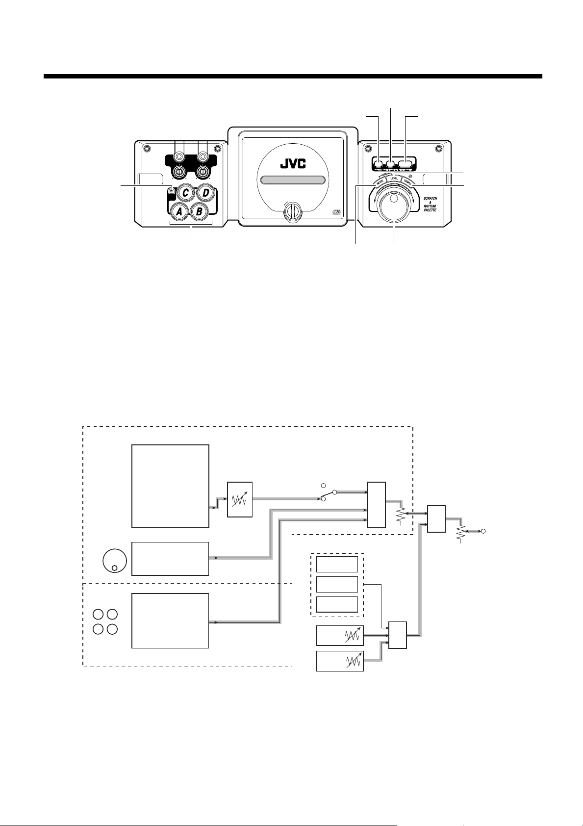
[RHYTHM MACHINE]
SCRATCH & RHYTHM PALETTE
MODE
(36 RHYTHM PATTERNS)
JOG DIAL
DRUM PAD
CD
A
B
• BASIC1 (8)
• BASIC2 ( 8)
• GROOVE1 (10)
• GROOVE2 (10)
(2 AMBIENT)
• WAVES
• BIRDS
SCRATCH
• SCRATCH (HIGH)
• SCRATCH (LOW)
PAD MODE
• STD DR
• PWR DR
• TOM+HI
• PERCUS
• VOICE
TEMPO
(60 - 160)
RHYTHM P
AMBIENT PATTERN(2)
SCRATCH SOUND (2)
DRUM PAD PATTERN (20)
MODE
Jog dial
You can play the Rhythm Machine alone or you can play it while
the other music source except Tuner is played.
The following shows the functional block diagram of the Rhythm
Machine. As an example, signal flows that may be used are shown
with the thick gray lines. From this example, you can see that the
scratch sound and the drum pad pattern can be mixed with the
Rhythm pattern. Also, you can see that the music source (MIC and
guitar in this example) can be mixed with the output of the Rhythm
Machine.
Tip:
When you are playing a CD as a mixing source, you can change
the playback pitch (playback speed) of the CD within ±12%, by
using the CD PITCH CONTROL button and Jog dial on the
Unit. For details, see "CD Pitch Control" on page 12.
Note: The Rhythm Machine does not work if Tuner is selected.
OFF
ATTERN (36)
RHYTHM
ON
MUSIC SOURCE
(EXCEPT TUNER)
CD
TAPE
AUX
MIC
MIX
LEVEL
(1 - 12)
MIX
MIX
MAIN
VOLUME
OUT
DRUM PAD PALETTE
GUITAR
Limitation on Rhythm Pattern's Sound:
The Rhythm Machine has three sound sources and the maximum number of sounds that can be generated from the Rhythm Machine at a time
is three.
Since two or three sounds are used for playing the rhythm pattern, the available sounds for playing the rhythm pattern will be reduced when
you generate the pad pattern and/or scratch sound. In this case, the rhythm pattern's sound will be changed.
Example:
The 8 BEAT-1 rhythm pattern you are playing uses three sounds.
• When you generate the pad pattern by pressing the Drum Pad A or when you generate the scratch sound by turning the Jog dial, t he number
of sounds that will be assigned to the 8 BEAT-1 rhythm pattern will be reduced to two.
• When you generate the pad pattern and scratch sound at the same time, the number of sounds that will b e assigned to the 8 BEAT-1 rhythm
pattern will be reduced to one
16
Page 20
Basic Operation-Adjusting the Rhythm Machine Volume
You can adjust the volume for the Rhythm Machine at any time except when Tuner is selected.
V
E
E
L
L
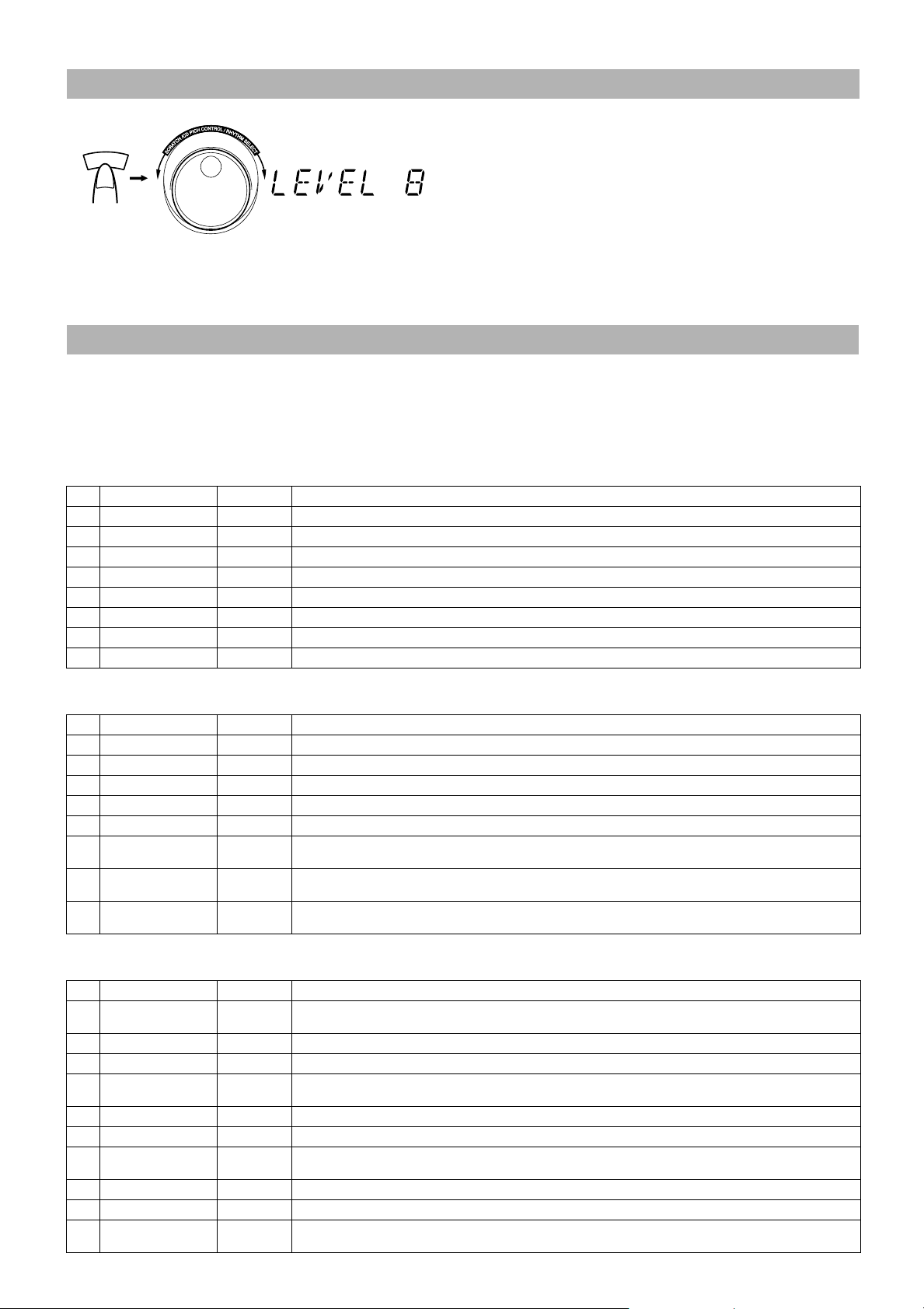
1. Press the LEVEL button on the Unit.
■
The current level will appear on the display for five seconds.
2. Within five seconds, turn the Jog dial to increase or decrease the volume level.
■
You can adjust the volume level for the Rhythm Machine between 1 and 12.
Playing the Rhythm Pattern
You can play one of 36 rhythm patterns or one of 2 ambient patterns shown in the "36-Rhythm/2-Ambient Pattern Table".
[36-Rhythm / 2-Ambient Pattern Table]
TEMPO: Initial Setting
BASIC1 (8 patterns)
■
2/4/8 BEAT Basic Rhythm Group:
Can be used for rock, pop, jazz and other music genres.
Can also be used for instrument practice or dance instruction.
No. Pattern Name Tempo Contents/Character
1 8BEAT-1 120 8BEAT pattern No. 1. 8 Beat Basic Pattern, Ideal for rock and pop.
2 8BEAT-2 132 8BEAT pattern No. 2. 8 Beat With Fill-In. Ideal for Rock Type Interval Sections, etc.
3 8BEAT-3 120 8BEAT pattern No. 3. Medium Tempo 8 Beat. Ideal for Slow Rock.
4 8BEAT-4 120 8BEAT pattern No. 4. Medium Tempo 8 Beat. Ideal for After-Beat type.
5 2BEAT-1 120 2BEAT pattern No. 1. Power Type 2 Beat. Suited to Punk Rock.
6 2BEAT-2 120 2BEAT pattern No. 2. Suited to Hard Rock and Heavy Metal.
7 4BEAT-1 112 4BEAT pattern No. 1. Ideal for Modern Jazz and Bebop.
8 4BEAT-2 90 4BEAT pattern No. 2. Ideal for Modern Jazz. Accents with high hat.
BASIC2 (8 patterns)
■
Ideal for playing at parties or for background music for latin or ethnic music from Latin America.
No. Pattern Name Tempo Contents/Character
1 SAMBA 120 Suited to samba-like sound.
2 SALSA 120 Suited to salsa-like sound.
3 REGGAE 80 Suited to reggae-like sound.
4 JUNGLE1 140 Suited to ethnic music.
5 JUNGLE2 140 Suited to ethnic music.
6 16BEAT1 120
7 16BEAT2 120
8 16BEAT3 120
GROOVE1 (10 patterns)
■
16 Beat Pattern No. 1
16 Beat Basic Pattern
16 Beat Pattern No. 2
Ideal for techno-type 16 beat/pops.
16 Beat Pattern No.3
Ideal for power type 16 beat.
Ideal for street performances with group music concentrating on "rap" or "house."
No. Pattern Name Tempo Contents/Character
DR'B-1
1
2
DR'B-2
3
DR'B-3
4
RAP-1
5 RAP-2 120 Rap Pattern No. 2
6 RAP-3 120 Rap Pattern No. 3
7 HOUSE-1 94
8 HOUSE-2 120 House Pattern No. 2
9 HOUSE-3 120 House Pattern No. 3
10 G-BEAT 94
160
160 Drum & Bass Pattern No. 2
160
120
Drum & Bass Pattern No. 1
Abbreviation for Drum & Bass
Drum & Bass Pattern No. 3
Rap Pattern No. 1
Rap Music: Simple rhythms plus talking voice
House Pattern No. 1
Common name for House Made Music
Ground Beat Pattern
Low tone + slow tempo and high hat for a laid-back sound.
17
Page 21
■GROOVE2 (10 patterns)
Ideal for creating and practicing the club sound which is popular now for group music concentrating on techno, funk and hip-hop.
No. Pattern Name Tempo Contents/Character
1 HIPHOP1
2 HIPHOP2 120 Hip-Hop Pattern No. 2
3 FUNK-1
4 FUNK-2 120 Funk Pattern No. 2
5 TECHNO1 120
6 TECHNO2 120
7 DANCE-1 120
8 DANCE-2 120
9 DANCE-3 120
10 MARIAN 120 Amusement Pattern with woman's voice (Marian).
120
120
Hip-Hop Pattern No. 1
Hip-Hop Music
Funk Pattern No. 1
Funk Music
Techno Pattern No. 1
Common name of Technology Music
Techno Pattern No. 2
Common name of Technology Music
Dance Pattern No. 1
Present dance scene. Image of Euro Disco type music.
Dance Pattern No. 2
Power Disco image
Dance Pattern No. 3
Street Dance image
■AMBIENT (2 patterns)
Tip:
It may be a good idea that you use WAVES and BIRDS to to fall asleep. For this setting, see"Setting the Sleep Timer" on page 24.
No. Pattern Name Contents/Character
1 WAVES Wavers beat upon the seashore.
2 BIRDS Birds sing.
E
D
O
M
(Within 5 seonds) (Within 5 seonds)
1. Press the MODE button on the Unit to select your favorite Rhythm mode.
■
RHYTHM ON/OFF
Each time you press the button, mode changes as follows.
BASIC1=BASIC2=GROOVE1=GROOVE2= AMBIENT= (back to the beginning)
• The display will return to the original one after five seconds.
2. Within five seconds, turn the Jog dial to select your favorite rhythm pattern.
■
Example 1:
If you select "BASIC1" in step 1, the pattern will change as follows as you turn the Jog dial clockwise.
8BEAT-1
=8BEAT-2=... =4BEAT-2= (back to the beginning)
Example 2:
If you select "AMBIENT" in step 1, the pattern will alternate as follows as you turn the Jog dial.
WAVES <---> BIRDS
3. Press the RHYTHM ON/OFF button on the Unit.
■
The selected pattern will be repeatedly played.
To stop playing, press the RHYTHM ON/OFF button once again. Switching the music source (e.g. from AUX to CD) will also stops
playing.
To restart playing, press the RHYTHM ON/OFF button again, the current pattern appears on the display and playback starts.
Note: You cannot play the rhythm pattern if Tuner is selected.
18
Page 22

Changing the Playing Rhythm
Pattern ———————————————
(During playing the
rhythm pattern)
1. During playing the rhythm pattern, press
■
E
D
O
M
(Within 5 seconds)
MODE button on the Unit to select your
favorite Rhythm mode.
2. Within five seconds, turn the Jog dial to
■
select your favorite rhythm pattern.
The selected rhythm pattern will be played.
(Playing rhythm
pattern changes.)
Adjusting the Tempo During
Playback ——————————————
1. During playing the rhythm pattern, press
■
the TEMPO button on the Unit.
The current tempo appears on the display for five seconds.
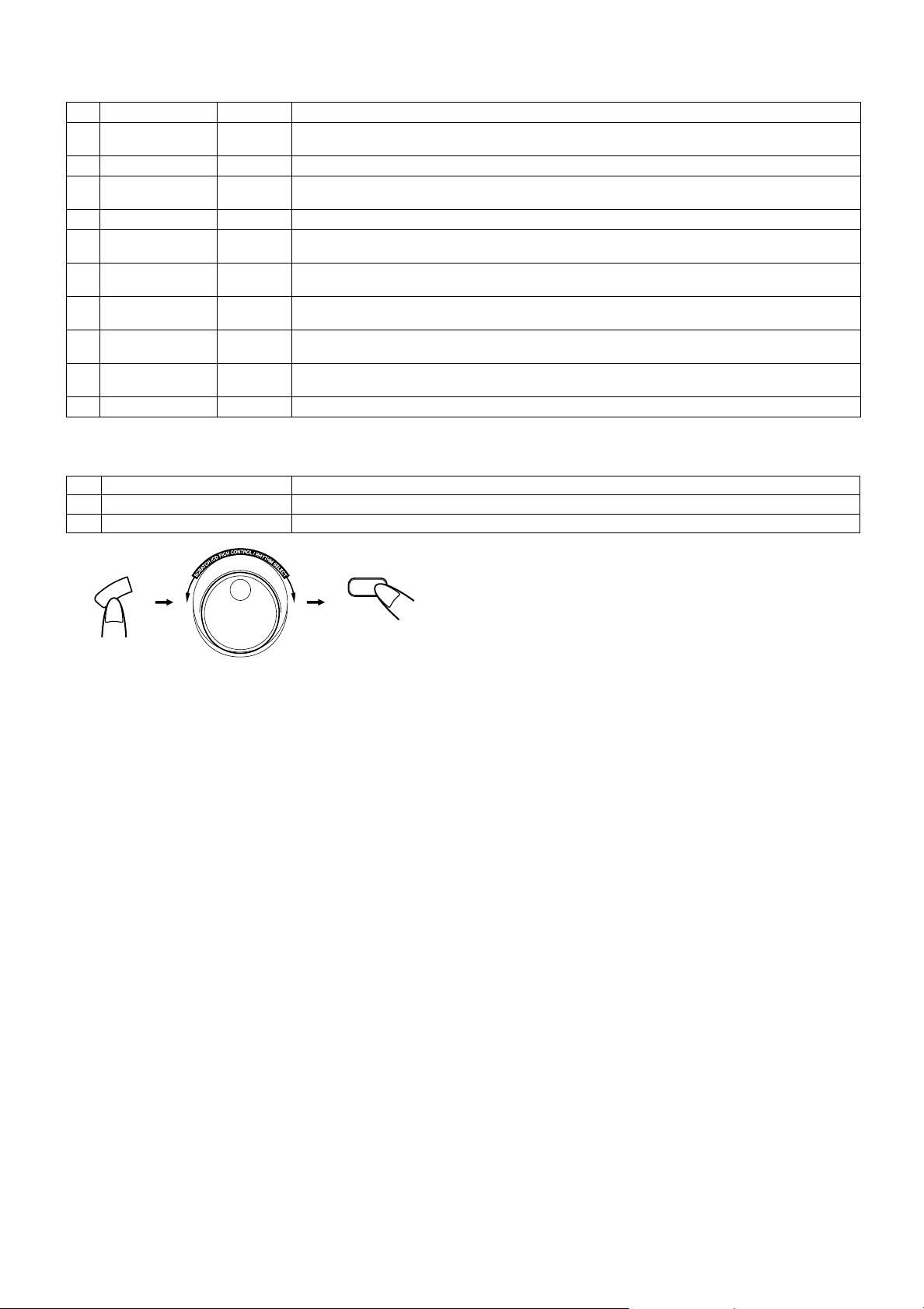
1. Press the SCRATCH button on the Unit.
■
"SCRATCH" will appear on the display.
2. Turn the Jog dial to generate the scratch
■
sound.
When you turn the Jog dial clockwise or counterclockwise, the
scratch-high sound or scratch-low sound will be generated, respectively. When you turn the Jog dial rapidly, the scratch
sound will be generated continuously.
To stop the scratch sound generation, press the
SCRATCH button once again to display "OFF".
Note: You cannot generate the scratch sound if Tuner is selected.
Generating the Pad Pattern
You can generate 20 pad patterns by pressing the Drum Pads A to
D on the Unit. Pad patterns are assigned to the Drum Pads A to D in
each Pad mode as shown in the "Pad Pattern Table".
The pad pattern can be mixed with the following all sources together.
• BIRDS, WAVES, or rhythm pattern generated from the
Rhythm Machine
• Scratch sound generated from the Rhythm Machine
• Music source except Tuner
• MIC and Guitar inputs
2. Within five seconds, turn the Jog dial to
■
increase or decrease the tempo.
You can adjust the tempo between 60 and 160.
• The tempo you have changed will be maintained even when
the System is turned off. However, it will be reset to the initial value when you select other rhythm pattern.
Generating Scratch Sound
You can generate two kinds of scratch sound (scratch-high and
scratch-low) by turning the Jog dial.
The scratch sound can be mixed with the following all sources together.
• BIRDS, WAVES, or rhythm pattern generated from the
Rhythm Machine
• Dram pad pattern generated from the Rhythm Machine
• Music source except Tuner
• MIC and Guitar inputs
SCRATCH
[Pad Pattern Table]
PAD MODE
1. Press the PAD MODE button on the Unit to
■
select Pad mode.
Each time you press the button, mode changes as follows.
STD DR=PWR DR=TOM+HI=PERCUS=VOICE=
OFF=(back to the beginning)
2. Press the Drum Pads A to D on the Unit.
■
Each time you press the Pad, corresponding pad pattern which
is shown in the "Pad Pattern Table" will be generated.
Note: You cannot play the Pad pattern if Tuner is selected.
PAD MODE
Pad
A Standard-Bass Drum Power-Bass Drum High Floor Tom High Agogo Sum —
B Standard Snare Power Snare
C Standard-Closed Hihat Power-Closed Hihat Open Hihat Open Hi Conga AY! —
D Power-Crash Cymbal
Abbreviations:
STD DR: Standard drum kit (bass, snare, high-hat, cymbal) PWR DR:Power drum kit TOM+HI:Tomtom and high-hat group
PERCUS:Percussion, ethnic percussion VOICE:Voice and onomatopoeic sounds
STD DR
(Standard Drum)
PWR DR
(Tom + Hihat)
Power-Crash Cymbal
TOM+HI
(Tom & Hihat)
Low Floor Tom
Pedal Hihat Hand Clap Engine —
PERCUS
(Percussion)
Low Agogo Yeh! —
VOICE
(Voice, etc.)
19
OFF
Page 23

Rhythm Machine Demo Mode
You can play the demo pattern repeatedly.
E
D
O
M
1. When the Rhythm Machine is stopped,
■
press and hold the MODE and LEVEL buttons on the Unit for more than two seconds.
Demonstration starts and a series of demo pattern is played.
ENGINE
=DR'B-1=DR'B-3=RAP-3=HIPHOP2=
FUNK-1=TECHNO1=HIPHOP1=DANCE2=
DANCE3=MARIAN= (back to the beginning)
2. Press the RHYTHM ON/OFF button on the
■
Unit to stop playing the demo pattern.
• Changing the music source (e.g. form AUX to CD) will also
stop playing.
Notes:
• You cannot change the level and tempo of the demo pattern.
• You cannot play the demo pattern if Tuner is selected.
and
V
E
E
L
L
(For 2 seconds)
20
Page 24

■■
Listening to an Auxiliary Equipment
TIMER
CLOCK
TIMER
ON/OFF
UP SET
PRESET
REW
MULTI CONTROL
REMOTE CONTROL
PROGRAM
AUTO
TREBLE
VOLUME
RM-SRVDP100E
SLEEP
RANDOM
REPEAT
TUNER
BAND
FM MODE
MID /
FF
AUX
DOWN
AUX CD TAPE
REVERSE MODE
DISPLAY
SUPER WOOFER
VOLUME
Listening to External
Equipment
You can listen to an auxiliary equipment.
■ First make sure that the auxiliary equipment is properly con-
nected to the System.(See page 3.)
SUPER WOOFER
VOLUME
STANDBY
STANDBY/ON
VOLUME
MID
TREBLE
/
REC
MID
/
TREBLE
OPEN
BAND
CD TAPE%AUX
TUNER
MULTI CONTROL
REW STOP FF
PRESET
ONE TOUCH
TUNING
AUX
1. Set the volume level to minimum.
■
2. Press the AUX button.
■
"AUX" appears on the display.
■ To listen to the auxiliary equipment, start playing the auxiliary
equipment.
3. Adjust the volume to the desired listening
■
level.
4. Apply sound effects, if you wish.
■
■ Adjust the super woofer volume to reinforce the bass sound.
■ Adjust the MID/TREBLE to control the tone. (See "Tone Con-
trol (MID/TREBLE)" on page 7.)
Note: For operation of the auxiliary equipment, refer to its In-
structions.
21
Page 25

■■
Using the Microphone/Guitar
MIC jack (Use a 6.3 mm diameter plug)
GUITAR Jack (Use a 6.3 mm diameter plug)
MIXING
PALETTE
MIC
PAD
MODE
DRUM
PAD
PALETTE
MIC LEVEL
MIN
MAX MIN MAX
Microphone Mixing
Using a microphone (not supplied), you can mix the microphone
sound with a source sound.
1. Set the MIC LEVEL control to MIN by turn-
■
ing it fully counterclockwise.
2. Open the rubber cap and connect a micro-
■
phone into the MIC jack on the Unit.
3. Start a source: CD, tape, tuner, Rhythm
■
Machine, or other equipment.
4. Adjust the main volume and the MIC LEVEL
■
control, as you sing into the microphone.
GUITAR
GUITAR LEVEL
1. Follow the above steps 1-4.
■
2. To record, follow the steps in "Standard
■
To Record Guitar Mixing on a
Tape
Recording". (See page 14.)
To Record Microphone Mixing
on a Tape
1. Follow the above steps 1-4.
■
2. To record, follow the steps in "Standard
■
Recording". (See page 14.)
Note: If "howling" occurs, keep the microphone away from the
Unit.
Guitar Mixing
Using a guitar, you can mix the guitar sound with a source sound.
CAUTION: DO NOT connect a bass guitar to
the GUITAR jack, as it may damage the System.
1. Set the GUITAR LEVEL control to MIN by
■
turning it fully counterclockwise.
2. Open the rubber cap and connect a guitar
■
into the GUITAR jack on the Unit.
3. Start a source: CD, tape, tuner, Rhythm
■
Machine, or other equipment.
4. Adjust the main volume and the GUITAR
■
LEVEL control, as you play the guitar.
22
Page 26

■■
CLOCK
DOWN
UP SET
TIMER
TIMER
ON/OFF
SLEEP
PROGRAM
RANDOM
REPEAT
DISPLAY
VOLUME
SUPER WOOFER
VOLUME
RM-SRVDP100E
REMOTE CONTROL
AUX CD TAPE
BAND
FM MODE
TUNER
AUTO
PRESET
REVERSE MODE
REW
MULTI CONTROL
FF
MID /
TREBLE
Using the Timers
TIMER
CLOCK
DOWN
TIMER ON/OFF
SET
SLEEP
UP
■
When the System is in use, the display shows other items as well.
For simplicity, we show here only the items described in this section.
The timers let you control listening and recording functions automatically.
Setting the Clock
When you supply the power using one of the following ways, the
"CLOCK" indicator blinks and "0:00" appears on the display. You
need to set the clock.
• Plugging the AC power cord into the wall outlet
• Loading 10 batteries into the Unit
• Connecting car battery (DC12V)
Use the Remote Control to set the clock.
Notes:
• The clock must be correctly set for the timers to work.
• The procedure must be completed within two minutes. Oth-
erwise, the setting is cleared and must be repeated from the
beginning.
CLOCK
DOWN
or
UP SET
TIMER
indicator
TIMER REC
indicator
ON time/OFF time indicator
CLOCK indicator
ON time, OFF time, Source, Volume
SLEEP indicator
Setting the Daily Timer
Once you have set the Daily Timer, the timer will be activated at the
same time every day, except for the Tuner REC timer which is used
to record a broadcast on the tape. It can be cancelled and reactivated
whenever you wish.
The Timer indicator ( ) on the display shows when the Daily
Timer you have set is in effect.
Use the Remote Control to set the Daily Timer.
Note: Perform each setting within 30 seconds. Otherwise, set-
ting is cleared and the procedure must be repeated from the
beginning.
1. Turn on the System.
■
2. Setting the ON time (Example: 12:15).
■
1. Press the TIMER button on the Remote Control.
The Timer indicator ( ) and "ON" indicator light up and
the current ON time blinks on the display.
1. Turn on the System.
■
2. Press the CLOCK button on the Remote
■
Control.
The time indication blinks on the display.
3. Press the UP or DOWN button to set the
■
time.
Press the UP or DOWN button to increase or decrease the time.
Pressing and holding the button will change the time rapidly.
4. Press the SET button.
■
The selected time is set and the seconds start counting from 0.
Then, the display returns to the original one.
CAUTION: If memory backup batteries are exhausted or not installed, and the AC power cord is
plugged in again after being disconnected, or
power is restored after a power failure, "CLOCK"
indicator will blink on the display. Set the current
time (clock) again.
23
2. Set the ON time by pressing the UP or DOWN button.
Pressing and holding the button will change the time rapidly.
3. Press the SET button.
The current OFF time blinks on the display.
Page 27

3. Setting the OFF time (Example: 13:15).
■
1. Set the OFF time by pressing the UP or DOWN button.
Pressing and holding the button will change the time rapidly.
CAUTION: If memory backup batteries are exhausted or not installed, and the AC power cord is
disconnected or there is a power failure, time settings will be erased from memory. If this happens,
set the current time (clock) and perform the timer
setting again.
2. Press the SET button.
The music source "TUNER" blinks on the display.
4. Selecting the music source.
■
1. Press the UP or DOWN button to select the music source
you want to listen to. The display changes as shown below:
TUNER
(back to the beginning)
• When you select the "TUNER REC", the "REC" indica-
• When you select the "TUNER REC", the timer will be
2. Press the SET button.
The volume level set by the previous time setting blinks on
the display.
5. Setting the volume level.
■
1. Press the UP or DOWN button to select the volume level.
0 to 50: When the timer is turned on, the Volume will be
2. Press the SET button.
The timer setting is completed and the display returns to the
display before you set the timer. The Timer indicator ( )
remains lit.
6. Before turning off the System, prepare the
■
music source selected in step 4.
TUNER : Tune in to the desired station.
TUNER REC
CD : Set a CD.
TAPE : Insert a tape.
RHYTHM : Select your favorite pattern from the 36
=TUNER REC=CD=TAPE=RHYTHM=
The "TUNER REC" (Tuner Recording) will be activated only when the system is operated on AC
power.
tor appears on the display.
released after Tuner Recording has been finished.
— : The current volume level will be used.
automatically set to the selected level.
: Tune in to the desired station and insert a
cassette tape for recording the station.
rhythm patterns.
Setting the Sleep Timer
Use the Sleep Timer to turn the System off after a certain number of
minutes when it is playing. By setting the Sleep Timer, you can fall
asleep to music and know that your System will turn off by itself
rather than play all night.
You can only set the Sleep Timer when the System is on and a
■
source is playing.
1. Play a CD, tape, tune in to the desired sta-
■
tion, or play the Rhythm Machine.
If you play "WAVES" in the Rhythm Machine, you may fall
asleep to the waves that beat upon the seashore.
2. Press the SLEEP button on the Remote
■
Control.
The SLEEP indicator lights up on the display.
3. Set the length of time you want the source
■
to play before shutting off.
• Each time you press the SLEEP button, it changes the number
of minutes shown on the display in this sequence:
30 = 60 = 90 = 120 = Cancelled (Original display)=
=
(back to the beginning)
After setting the number of minutes for the Sleep Timer, the display
will stop blinking and return to the display as before setting the
Sleep Timer.
The System is now set to turn off after the number of minutes you
set.
To Confirm the Sleep Time:
When the SLEEP button is pressed, the remaining sleep time is displayed. Wait until the display returns to the original display.
To Cancel the SLEEP Timer Setting:
Press the SLEEP button until the original display appears on the display. Turning off the System also cancels the SLEEP Timer.
If you are setting the Daily Timer, the System will be turned on
■
at the set time to wake you up.
7. Turn off the System.
■
• When the timer turns on, the volume level gradually increases
from 0 (zero) to the preset level in step 5.
To cancel the operation, press the TIMER button until the display returns to the original one.
To cancel the timer, press the TIMER ON/OFF button. The Timer indicator ( ) goes out on the display.
To reactivate the cancelled timer, press the TIMER ON/OFF
button to light the Timer indicator ( ).
To confirm the timer settings, press the TIMER button. Then,
press the SET button repeatedly to see the current timer settings
(ON time, OFF time, source, and volume).
To change the timer setting, repeat the setting procedure from
the beginning.
24
Page 28

■■
Pinch-rollers
Record/play head
Capstans
Erase head
Care And Maintenance
Handle your CDs carefully, and they will last a long time.
Compact Discs
• Only CDs bearing this mark can be used with
this System. However, continued use of irregular shape CDs (heart-shape, octagonal, etc.)
can damage the System.
• Remove the CD from its case by holding it at
the edges while pressing the case’s center hole
lightly.
• Do not touch the shiny surface of the CD, or
bend the CD.
• Put the CD back in its case after use to prevent
warping.
• Be careful not to scratch the surface of the CD
when placing it back in the case.
• Avoid exposure to direct sunlight, temperature
extremes, and moisture.
• A dirty CD may not play correctly. If a CD
does become dirty, wipe it with a sof t cloth in a
straight line from center to edge.
• If there are fingerprints, etc. on the lens, gently wipe clean with
a cotton swab.
Moisture Condensation
Moisture may condense on the lens inside the
System in the following cases:
• After turning on heating in the room.
• In a damp room.
• If the System is brought directly from a cold
to a warm place.
Should this occur, the System may malfunction.
In this case, leave the System turned on for a
few hours until the moisture evaporates, unplug
the AC power cord, and then plug it in again.
Cassette Tapes
• If the tape is loose, it may get stretched, cut, or
caught in the cassette. Take up the slack by
inserting a pencil in one of the reels and rotating.
CAUTION: Do not use any solvent (for example,
conventional record cleaner, spray thinner, benzine, etc.) to clean a CD.
General Notes
In general, you will have the best performance by keeping your CDs and the
mechanism clean.
• Store CDs in their cases, and keep them in cabinets or on
shelves.
• Keep the system’s CD cover closed when not in use.
Cleaning the lens
If the lens in the CD pickup is dirty, dropout, etc., could degrade sound.
Open the CD cover and clean the lens as shown.
• Use a blower (available from a camera store) to blow dust off
the lens.
Blower
Lens
• Do not touch the tape surface.
• Do not store the tape:
- In dusty places
- In direct sunlight or heat
- In moist areas
- On a TV or speaker
- Near a magnet
Cassette Deck
• If the heads, capstans, or pinch-rollers of the Cassette Deck
become dirty, the following may occur:
- Loss of sound quality
- Discontinuous sound
-Fading
- Incomplete erasure
- Difficulty recording
• Clean the heads, capstans, and pinch-rollers using a cotton
swab moistened with alcohol.
25
• If the heads become magnetized, the System will produce noise
or lose high frequency notes.
• To demagnetize the heads, turn off the System, and use a head
demagnetizer (available at electronics and record shops).
Page 29

■■
• If you are having a problem with your System, check this list for a possible solution before calling for service.
• If you cannot solve the problem from the hints gi v en here, or the System has been physically damaged, call a qualif ied person, such as your
dealer, for service.
Troubleshooting
Symptom Possible Cause Action
No sound is heard. • Connections are incorrect, or loose.
• Headphones are connected.
Unable to record. Cassette record protect tabs are removed. Cover the holes on the back edge of the cassette
Poor FM reception The FM telescopic antenna is not properly
extended and positioned.
The CD skips. The CD is dirty or scratched. Clean or replace the CD.
The CD does not play. The CD is upside down. Put the CD in with the label side up.
Unable to operate the Remote Control. • The path between the Remote Control and the
sensor on the Unit is blocked.
• The batteries have lost their charge.
Operations are disabled. The built-in microprocessor has malfunctioned
due to external electrical interference.
The cassette holder cannot be opened. During tape playing, the power cord was
unplugged.
• Check all connections and make corrections.
(See page 3.)
• Disconnect the headphones.
with tape.
Fully extend the FM telescopic antenna and turn it
for the best reception.
• Remove the obstruction.
• Replace the batteries.
Unplug the System then plug it back in after a few
minutes.
Plug in the power cord and press the % button.
26
Page 30

■■
Specifications
Amplifier
Output Power
(Max.) 20 W (10 W + 10 W) at 4 Ω (full range)
(10% THD) 10 W (5 W + 5 W) at 4 Ω (full range)
Input Sensitivity/Impedance (1 kHz)
Output Sensitivity/Impedance (1 kHz)
Cassette Deck
Frequency Response
Wow and Flutter 0.15% (WRMS)
Wow And Flutter Unmeasurable
AUX IN 300 mV/47 kΩ
MIC
GUITAR
Phones 16 Ω - 1 kΩ
TypeII (CrO
CD Player
FM Tuner
Tuning Range 87.5 MHz - 108.0 MHz
AM Tuner
Tuning Range (MW) 522 kHz - 1 629 kHz
2) 60 Hz - 14 kHz
Tuner
Antenna FM telescopic antenna
40 W (20 W + 20 W) at 4 Ω , 60 Hz (woofer)
32 W (16 W + 16 W) at 4 Ω , 60 Hz (woofer)
200 Ω - 2 kΩ (6.3 mm dia. plug)
100 kΩ - 1 MΩ (6.3 mm dia. plug)
0 - 12 mW/ch output into 32 Ω
(LW) 144 kHz - 288 kHz
Ferrite core antenna for AM (MW/LW )
Speakers
Full range 8 cm × 2, 4 Ω
Super woofer 16 cm × 2, 4 Ω
General
Dimensions 634 mm × 256.5 mm × 311 mm (W/H/D)
Mass 10.2 kg (without batteries)
11.3 kg (with batteries)
Accessories
Power Specifications
Power Requirements AC 230 V ~ , 50 Hz
Power Consumption 44 W (power on mode)
Design and specifications are subject to change without notice.
Power Cord (1)
Remote Control (1)
Batteries R6P (SUM-3) / AA (15F) (2)
Shoulder Strap (1)
DC15V ("R20/D (13F)" batteries (10))
External DC12V (car battery via optional CA-R120E car adaptor)
2 W (in Standby mode)
27
Page 31

VICTOR COMPANY OF JAPAN, LIMITED
EN 0201MNMCREJEIN
Page 32

RV-DP200BK
Block diagrams
System control (Microm) section
5
Q9001
L C D
POWER
4
VR
CN921CN923
CN911
IC901
Q9002
X9002
IC201
IC251
RIMOCON
3
DRAM
PAD
FW913
SYSTEM MICROM
RHYTHM
GENERATOR
IC232
RHYTHM
AMP.
RHYTHM
PAD
CN924
FW914
Q201
2
IC603
DIGITAL
SERVO
DIGITAL
PROCESSOR
CN421 CN422
CD OUT RHYTHM OUT
PIC UP
CN601
IC601
RF & SERVO
MOTOR
1
A
CN602
B
IC602
BTL DRIVER
C
D
2-1
Page 33

RV-DP200BK
Mic/Guitar and AUX/Headphone section
5
GUITAR
CN961
CN951
5
MIC / GUITAR AMPMIC / GUITAR JACK
IC961
GUIT AR VR
VR961
GUITAR
1
57
IC962
3
7
MIC
CN424
JACK IN
4
MIC
3
MIC VR
VR951
IC951
1
5
Q9501 Q9502
7
3
AUX/HEADPHONE
AUX
Q4131
MUTE
Q4331
FW429FW420
2
HEADPHONE
H.PHONE AMP
1
2-2
A
Q6150
Q6351
B
IC615
13
MUTE
C
Page 34

Tuner / Power section
RV-DP200BK
TUNER
5
TBOSC
22
L12
4
OSC
20
2
PLL IC2
21
IC1
CN1
3
1
POWER AMP
POWER SUPPLY
2
POWER AMP
13 3
CN427
211
CN418
IC631
WOOFER AMP
IC641
CN196
FW106
157
FW107
CN192
1
A
B
C
D
2-3
Page 35

RV-DP200BK
Function section
FUNCTION
5
4
AUX
MIC
GUITAR
TUNER
CASSET
RHYTHM
DRAM
CD
CN419
FW414CN415CN412
CN413
CN411
E VOLUME
2 9
IC501
IC701
BASS BOOST
31
IC801
IC702 IC703
IC704
ILLUMINATION
CN401
HEAD PHONE
CN410
POWER AMP
CN427
POWER AMP
(WOOFER)
CN418
3
LED section
2
IC491
FW491
1
2-4
A
B
C
Page 36

RV-DP200BK
Standard schematic diagrams
CD servo control section
270K
R605
150K
R606
R612
0.0047
C611
C618
1K
150K
R610
C617
0.022
0.0022
R697
470K
BDO
OFT
RFDET
0.01
1.2M
C612
R603
C613
330P
TP601
C623
0.1
C604
27K
R609
100K
270P
C619
0.022
C616
0.1
C614
C628
C629
1/50
C608
R607
ARF
C620
180P
AN8806SB
100P
0.027
C609
C610
0.047
100/10
R616
F
E
0.001
0.001
C607
C606
D
A
C641
0.022
C622
47/25
A
F
D
E
R615
R613
12
Q601
2SB698/EF/-T
120
10
C605
R614
91
F+
T+
TF-
0.022
C615
IC601
LDON
11K
R601
10/50
5
1
4
2KB
HDU-100
HQMV7102-015
P001
CN601
3
33
33
33
100/10
RFENV
TRCRS
VDET
TBAL
FBAL
FE
TE
OFT
RFDET
BDO
LDON
ARF
FBAL
TBAL
FE
TE
RFENV
VDET
TRCRS
TRV
TVD
ECM
ECS
KICK
TRD
FOD
0.022
C653
R651
XRST
1K
STAT
1K
R652
SUBQ
1K
R653
IC603
SQCK
1K
R654
C694
150P
MN35510
C691
150P
C692
150P
C693
150P
MLD
MCLK
MDATA
C655
0.047
DMUTE
SUBQ
SQCK
STAT
XRST
MCLK
MDATA
MLD
REST
CDSAFETY
MG
CD+B
CDL
CDR
To G-2 on page 2-8
22
R666
C674
0.022
220/10
C673
D661
C675
0.001
MA165-T2
10K
R671
0.0022
C671
K9004
10K
R672
0.0022
C672
CD & Main signal
R623
R622
470/10
C631
R621
C696
R641
R642
T+
T-
100P
C699
56K
12K
R643
R644
FM+
FM-
100P
2
IC602
FM+
SMSM+
FM-
CN602
QGA2001C1-06
C640
1
0.0082
C698
F+
R696
100P
F-
2.2K
2SB698/EF/-T
Q631
R631
27K
330
R633
R632
100
C632
100/10
C697
SM-
BA6897FP-W
100P
SM+
R645
R646
R647
KICK
TRD
TVD
8.2K
TRV
22K
TP602
K696
ECM
22K
ECS
2.2K
FOD
4.7K
C661
470P
0.022
C662
1.5M
R662
68K
R661
0.022
C663
0.022
C664
120K
R663
470
R664
0.1
C665
5.6K
R665
1/50
C668
0.047
C667
C666
1000P
C651
27P
C652
27P
220
R659
X651
QAX0369-001Z
Parts are safety assurance parts.
When replacing those parts make
sure to use the specified one.
A
B
C
D
EF
HG
2-5
Page 37

RV-DP200BK
1.5
Cassette amplifier section
SG-10SF3
IC1
FA1A4ZX
R110
Q102
2.7K
R113
R114
4.7K
4.7K
C112
C111
0.0012
C211
0.0056
R213
C212
R214
4.7K
Q202
FA1A4ZX
MA152WA-TX
Q304
2SC2001( L,K)
0.068
R112
R111
R211
R212
2.2K
0.068
2.7K
Q302
2SC2001( K)
C308
Q323
2SC1623( 6) X
33K
D301
R315
2.2K
33K
C307
0.01
FN1L4MX
10
0.0056
R306
2.2K
R314
Q301
Q375
2SB562( C)
R305
2.2K
C310
0.022
22K
R335
1.5K
FA1L4MX
Q321
D309
MA704AX
C375
100/10
Q376
2SC1623( 6) X
R375
C376
0.01
150
R376
4.7K
D375
MA3051( M) TX
Q371
0.0022
0.0012
0.0022
4.7K
C309
10
22K
R317
B199
0
560P
4.7/25
22/16
10/16
10/16
3.3K
560P
C207
22/16
C107
C109
C305
C304
3.3K
C306
47/16
C108
4.7/25
220/6.3
4.7/25
0.039
C302
C303
C208
4.7/25
39K
C209
R303
R108
5.6K
R104
1.2K
R304
IC32
AN7317
R204
R208
R109
1.2K
C113
100
C213
1.2K
5.6K
1.2K
R210
R209
100K
R103
R203
Q201
0.0022
C105
R105
R106
2.4K2.4K
R102
C106
R202
1.8K
C206
R206
100K
0.0022
R205
C205
22
R101
5
BA3126N
IC31
R301
220
4
VGH0425-544
VMC0163-R06
CN31
C301
100/10
R107
R207
12K
12K
R216
1K
R116
C110
0.0068
C210
0.0068
1K
820P
C101
220P
820P
C201
C103
220/6.3
Q101
FA1A4ZX 1.8K
C102
220P
C202
C204
0.033
C203
220/6.3
22
R201
0.033
C104
FA1A4ZX
3
QVPA603-503AZ
VR31
L303
C351
C311
10/16
0.0068
100/10
C313
R351
R352
VQP0033-100Z
C314C315
68k
9.1K
R316
Q303
R313
R310
3.3
56
R311
Q305
2SC2001( L,K)
2SC2001( K)
56
1.5
QVPA603-503AZ
VR32
L301
R319
1.5K
820P
Q307
2SC1623( 6) X
2SC1623( 6) X
C318
Q306
12K
R332
0.01
C319
12K
QQR0620-001
0.01
C316
1K
1K
C322
0.0015
Q309
2SC1623( 6) X
C121
330P
C221
330P
R322
1.5K
Q308
2SC1623( 6) X
C321
0.01
R333
R121
R221
R325
560P
C326
Q310
2SC1623( 6) X
R326
1.5K
12K
C324
R334
47K
0.01
R327
470K
C325
0.0039
2
Q311
2SC1623( 6) X
VWS304-06A13K
VR37
QVPA603-103AZM
2SA952( L,K)
R372
1K
IC33
SW4
R371
Q372
FA1F4MX
BU4094BCF
R339
2.2K
R336
4.7K
SW5
FW31
12K
SW6
SW1
SW2
QSEC001-E03
MSI-5U2LWA
C374
100/10
R338
C371
4.7/25
3.9K
R337
3.3K
390
R340
47/16
C331
D1
1SR139-100T
R341
20K
R342
CN1
CN32
QGB2011M1-10
12K
R343
VGP2401-00A
EMV7159-010
18K
VMC0163-R10
CN34
CN33
VMC0163-R09
1
Tape P.B. signal
To E-1 on page 2-8
HG
A
B
C
2-6
D
Recording signal
To A-2 on page 2-9
EF
Page 38

Tuner section
Q2
RV-DP200BK
2SC2668/O/-T
R34
2.2K
C22
5
2SA1175/HFE/-T
Q4
R67
TC2TC3
180K
QQR0771--001
Q5
4
QNZ0104-001
QNZ0104-001
3
L12
TP1
C81
15P
QQR0756-001
TP2
D5
D6
C83
56P
L2
QQR0769-001
C52
0.001
R7
100K
SVC203SPA-JV-T
C6
5.6P
C3
C85
15P
0.01
R1
D1
SVC203SPA-JV-T
R2
47K
100K
C13
0.022
D2
R3
22
12P
C77
0.01
L1
QQR0772-001
R54
2.2K
C16
0.01
0.01
C7
4.7K
C9
R4
47K
R9
2SC2668/O/-T
R15
2.2K
R14
10K
62P
C24
SVC344-T
R20
22K
R21
22K
C32
D8
C21
0.047
2SC2668/O/-T
C25
0.047
0.01
QFP31HJ-431Z
R16
4.7K
R17
R13
180P
C27
100K
Q6
C26
100P
C28
12P
100K
C23
2SC2668/O/-T
L6
15P
QQR0723-001
Q3
QQR0774-001
1K
R48
0.001
C31
L4
1K
R18
680
0.01
C40
47K
330P
C51
C44
R32
C41
3.3K
4.7/50
1/50
C45
0.1/50
C43
0.1/50
0.015
C47
R35
18K
4.7K
R12
Q14
R19
2.2K
56
R37
R25
1K
22
R47
IC1
TA2104AN
R24
Q1
2SC2668/O/-T
18K
330P
C35
0.047
D13
C71
R56
3.3K
0.0022
C69
0.001
2
12P
C64
X1
12P 100K
C62
C63
0.001
C60
L7
QAX0402-001
L10
1
100/10
C61
QQL231K-221Y
IC2
LC72136N
QQL231K-4R7Y
R42
47K
1K
R61
2.2K
R55
1K
R59
R52
C70
2.2/50
10K
R60
10/16
R41
2.2K
2.2K
R44
R40
0.001
C65
1K
2.2K
0.001
C37
R57
1K
R33
470
T2
QAX0540-001
330
1K
R51
R45
R63
47K
R30
C30
C42
0.047
CF1
4.7/50
C36
QAX0403-001
R39
68
CF3
R38
100
QAX0538-001Z
D12
DSK10C-T1
R31
1K
R64
AM signal
0.015
C33
100/10
C48
C50
18K
R36
C49
0.1/50
0.1/50
CN1
QGF1205C1-09
GND
6V
DATA
PERIOD
To A-3 on page 2-9
FM / RADIO signal
A
B
C
D
EF
HG
2-7
Page 39

RV-DP200BK
System control section
S2531
QSW0122-001
FW922
QGA2501C1-02
CN912
Q9002
5
S2510
1.8K
S2509
R2508 R2509
QSW0622-001ZQSW0622-001ZQSW0622-001ZQSW0622-001ZQSW0622-001ZQSW0622-001ZQSW0622-001ZQSW0622-001ZQSW0622-001ZQSW0622-001ZQSW0622-001Z
S2520
4
Q2501
DTA124XKA-X
120
R2530
D2502
SLR-342VR-T15
D2503
150
3
VR902
C2504
QSW0868-001
C2503
VR901
C2502
QSW0868-001
C2501
R2534
0.01
0.01
0.01
0.01
S2508
S2507
S2506
S2505
S2504
S2503
S2502
S2501
R2506
R2505R2503
R2504
R2502
R2501
R2500 R2507
390270
220 1K
180
120
100
100 560
2SC2668/O/-T
Q9001
2SC2668/O/-T
C9031
C9032
C9034
C9035
QAX0401-001
C9029
R9028
8.2K
R9025
8.2K
2
IC251
RPM6938-SV4
C2505
47/16
CN921
QGF1205F1-14
CN911
QGF1205F1-14
R9027
2.2K
36P
X9002
QAX0416-001Z
36P
C9033
R9024
2.2K
150P
22P
X9001
22P
REGSAFETY
TAPE0
TDATASI
MPX
2SC2412K/R/-X
C9030
56P
56P
R9008
R9012
R9015
R9017
R9019
L9001
R9026
R9022
C9001
C9002
C9003
C9004
C9005
R9111
Q9009
K9001
R9029
9.1K
QLD0121-001
DI901
C9036
R9058
R9112
4.7K
1000P
R9004
39K
R9001R9002R9003
100K100K100K
R9005
R9006
*
1K
1K
1K
1K
10K
10K
0.001
0.001
0.001
0.001
0.01
47K
4.7K
C9025
0.01
C9026
100/10
**
L9002
D9001
9.1K
R9059
REST1
**
R9007
R9009
R9010
R9011
R9013
R9014
R9016
R9018
R9020
R9021
150P
68P
C9007
C9006
SCK
C9008
SEG29
SEG28
SEG27
SEG26
SEG25
SEG24
SEG23
SEG22
SEG21
SEG20
SEG19
SEG18
SEG17
SEG16
SEG15
SEG14
SEG13
SEG12
SEG11
SEG10
SEG9
SEG8
SEG7
SEG6
SEG5
SEG4
SEG3
SEG2
SEG1
SEG0
COM3
COM2
COM1
COM0
SEG0
SEG1
SEG2
SEG3
SEG4
SEG5
SEG6
SEG7
SEG8
SEG9
SEG10
SEG11
SEG12
SEG13
SEG14
SEG15
SEG16
SEG17
SEG18
SEG19
SEG20
SEG21
SEG22
SEG23
SEG24
R9052
POUT
R9061
47K
R9063
R9102
2.2K
R9062
47K
R9064
10K
R9065
10K
10K
1K
R9066
R9068
PLAY
REEL
IC902
IC-PST9131-T
SEG25
SEG26
SEG27
SEG28
SEG29
150P
C9013
100K
R9067
C9027
0.01
C9022
10K
R9078
10K
R9077
10K
R9076
10K
R9074
1K
R9075
1K
R9073
5.6K
R9079
2.2K
R9080
1K
R9081
1K
R9082
4.7K
R9072
4.7K
R9071
4.7K
R9070
1K
R9060
2.2K
R9057
R9056
1K
1K
R9055
1K
R9054
1K
R9053
2.2K
R9069
47K
56K
47K
R9109
R9110
R9108
R9100
D9003
MA700A-T2
Q9003
2.2K
R9103
0.01
22/16
C9028
2SC2412K/R/-X
100K
AC/DC
R9099
47K
C9016
C9015
C9014
C9018
C9019
C9020
C9021
C9017
R9098
PBMUTE
FAUX
FTU
FCD
WOUT3
WOUT2
WOUT1
STAT
DMUTE
XRST1
MDATA1
MCLK1
MLD1
LATCH
0.001
150P
150P
150P
150P
150P
150P
150P
D9002
MTZJ5.1C-T2
33K
COM3
COM2
COM1
COM0
10K
R9034
10K
R9035
2.2K
R9036
2.2K
R9037
6.8K
R9038
VOL
10K
R9039
MID
Q9010
IC901
10K
10K
10K
R9040
R9043
R9044
TRE
R9101
100K
2SA1037AK/RS/-X
10K
R9045
2.2K
R9046
47K
R9047
2.2K
R9048
47K
R9049
2.2K
R9050
SMUTE
10K1K2.2K
R9051
100K
220K
2.2K
2.2K
2.2K
2.2K
2.2K
2.2K
2.2K
2.2K
6.8K**
*
2.2K
1K1K1K
R9030
R9031
R9032
R9033
24K
24K
10/16
150P
100P
C9009
C9010
R9041
10/16
C9011
R9042
10/16
C9012
SUBQ
SQCK
QSW0882-001Z
QSW0622-001Z
QSW0622-001Z
QSW0622-001Z
QSW0622-001Z
CN923
QGA2501F1-03
FW913
R9087
4.7K
R9090
10K
XRST1
MCLK1
MDATA1
MLD1
REST1
CDSAFETY1
R2513R2512R2511 R2514
R2515
C9024
K9002
K9003
L9003
C9023
220
180
120100
100
R9085
0.01
5.1K
3.6K
1K
R2524 R2525
R2523R2522R2521
560
390
270
QSW0622-001Z
QSW0622-001Z
QSW0622-001Z
QSW0622-001ZQSW0622-001Z
QSW0622-001Z
CN915
QGA2501C1-03
S2511
S2525
S2524
S2523
S2522
S2521
CN924
FW914
VR903
QSW0869-001
C2506
0.01
C2507
0.01
QGA2501F1-06
RY-XTAL
SW5V
RY-MUTE
RY-BCNT
RY-RSTB
RY-MCK
RY-MSD
RY-LAB
To G-1 on page 2-10
PL1
QLL0052-002
FW925
To H-4 on page 2-5
S2526
Q9004
2SB624/4/-X
4.7K
R9084
Q9006
2SC2412K/R/-X
Q9005
2SC2412K/R/-X
1K
1K
1K
1K
4.7K
R2510
DMUTE
SUBQ
SQCK
STAT
XRST
DG
MCLK
MDATA
MLD
REST
CDSAFETY
MG
CD+B
CDL
AG
CDR
S2527
S2528
S2529
S2530
4.7K4.7K
R9083R9086
4.7K
47/16
R9088
10K
100K
R9089
R9091
R9092
R9093
R9094
R9095
D9004
**
**
**
SW9V
RY-R
RY-L
To G-2 on page 2-10
1
QGF1205F1-17
JACK
REGSAFETY
CDSAFETY1
PERIODE
TDATASI
SCK
MPX
CN421 CN422
To B-1 on page 2-9
A
B
C
QGF1205F1-17
AC/DC
SMUTE
POUT
TRE
MID
VOL
WOUT1
WOUT2
WOUT3
FAUX
PBMUTE
FTU
FCD
REEL
PLAY
TAPE0
To G-1 on page 2-6
2-8
D
CN916
QGF1205F1-09
LATCH
TDATASI
SCK
CD & Main signal
Rhythm signal
EF
HG
Page 40

RV-DP200BK
AC/DC
FAUX
Function section
QGA2501F1-06
33K
100K
VOL
5
R4247
R4245
R4246
R4291
R4191
C4243
4
FW414
MICSIG
GUISIG
To D-1 on page 2-10
CL
3
2
DATA
6V
LCH
RCH
To G-1 on page 2-7
CN413
CN401
To G-2 on page 2-11
RECL
RECR
PBL
PBR
To E-1 on page 2-6
CN415
QGF1205F1-09
QGA2501F1-03
QGF1205F1-10
1
CDR
CD+B
CDL
R4143
220K
C4142
15P
0.47/50
C4245
C4143
R4145
R4146
120K
C4151
680P 18K
C4251
43k
REGSAFETY
US6V
C4242
R4243
10/35
C4145
R4147
120K
R4152
R4252
MPX
CDSAFETY1
IC401
BA15218F-W
R4341
10K
10K
R4342
*
R4153
R4253
R4164
R4264
R4161
R4261
JACK
R4151
150K
47K
R4251
R4162
1K
820
R4262
2SD596/4/-X
SCK
TDATASI
47/16
C4341
33K
BUP
R4163
PERIODE
100/16
C4342
3.3K
Q4161
C4361
CN411
QGF1205F1-17
To D-1 on page 2-8
100
R4343
22/16
R4165
C5207
R5201
R4142
C4244
R5303
C5203
R5305
MTZJ3.9B-T2
Q3402
2SC2412K/R/-X
1K
R3402
CN412
QGF1205F1-17
RY-L
0.47/50
C5309
C5103
D3403
100
R3401
TDATASI
C5303
10/16
C5305
39
R5308
SCK
R5302
2.2/50
150K
1/50
C5302
100/16
IC501
R3403
WOUT2
C5204
0.056
C5104
C3401
100/10
4.7K
C3402
Q4351
DTC144TKA-X
FCD
WOUT3
FTU
FAUX
BH3852S
D3402
D3401
4.7/25
C5205
0.056
C5105
2SA1037AK/RS/-X
Q4352
DTC144TKA-X
PBMUTE
RY-R
C5206
C5106
0.0056
Q3401
R5202
C5202
C5301
10/16
C5102
R5101
22K
C5107
0.0018
30K
R4242
C4144
PERIODE
R4263
Q4261
5.6K
R4265
4.7/25
JACK
VOL
4.7/25
15K
R5102
MPX
WOUT1
MID
TRE
SMUTE
AC/DC
POUT
TRE
1/50
C5304
C5306
CN419
100K
R5301
FTU
MID
4.7/25
To C-4,5 on page 2-10
OUT1
LAUX
RAUX
C7301
47K
IC701
R7301
C7302
0.47/50
100/16
100
R7303
BA15218F-W
R7307
390K
C7303
3.3P
R7308
100K
BUP
CDSAFETY1
FCD
D7307
OUT2
C7305
MTZJ4.3B-T2
R7309
33K
R7317
100K
MUTING
4.7/50
Q7303
R7305
220K
R3204R3203
CN410
QGA2501F1-07
R5207
0.47/50
C5308
R5107
C7306
0.27
R7311
2SK105/EF/-T
C7310
0.015
4.7K8.2K
D3195
Q3198
DTC114TKA-X
100K
C7309
180K
100K
R7313
R7344
R8321
R8301
D8301
100/16
D7305
100
1K
R7310
100K
R8201
R8204
47/16
MTZJ4.3B-T2
C8301
100
R7314
27K
C7308
0.01
R7312
100K
D7306
C7324
10/16
D3194
R3202
1.5K
1.5K
R3201
R8101
3.3K
47/16
C8302
R7316
MTZJ7.5A-T2
C3194
R8202
R8104
100K
R8102
100K
QQL28AK-101
C8201
C8101
0.056
2.7K
IC702
2K
R7319
2SC2412K/R/-X
L3191
100/25
C8202
C8102
0.056
C7314
BA15218F-W
220
R7320
Q7302
2SC2412K/R/-X
Q7301
R3200
C3193
D3193
SRT14
R8203
C8203
IC801
C8103
47/25
R8103
3.9K
100
R7318
100/16
BA15218F-W
IC703
C7312
2SA934/QR/-T
12K100P
R8205
BA15218F-W
3.3K
R8105
12K
R8106
Q8101
2SC2412K/R/-X
D7302
D7301
1K
R7323
C7313
4.7/50
R7324
10K
R7322R7321
56K220K
1/50
Q3196
Q3197
2SC2785/FE/-T
R8111 R8211
220K
18K
R7342
R3199
D3192
R8327
100
10K
R7325
C7316
4.7/50
D7303
D7304
47K
R3197
R3198
MTZJ7.5A-T2
R8206
Q8201
0.15
0.1
C7321
C7317
R7330
10K
1K
R7329
D3191
QAD0015-153Z
Q3195
2SA1175/HFE/-T
4.7K
D3196
0.039
C7320
R7331
R3195
R3196
R8302
C7319
0.1
R7336
4.7K
2.2K
10K
470K
C8303
24K
3.3K
R7328
C3192
C7318
R7334
24K
IC704
BA15218F-W
4.7/50
1/50
100/16
C7311
100/25
R3194
R7332
R7327
1M
10K
100
C3191
R7333
15K
R8207
10K
R8107
R7338
120K
R7326
4.7/50
MIC & Guitar signal
Rhythm signal
Woofer signal
10/16
15K
1/50
C7322
R7351
15K
AUX signal
C7323
R7354
15K
Q7305 Q7307
1K
R7352
Q7304
DTC114EKA-X
R7353
12K
1.8K
R7356
DTC114EKA-X
1K
R7355
WOUT1
R7358
Q7306
DTC114EKA-X
1K
R7357
WOUT2
4.7K
R7360
DTC114EKA-X
1K
R7359
WOUT3
Q3801
2SC2001/LK/-T
100/16
15K
Q7308
DTC114EKA-X
C3802
TAPE P.B. signal
CD & main signal
FM / Radio signal
Recording signal
C3801
470/10
R3802
330
OUTR
OUTL
AHB.C
REGSAFETY
SMUTE
D7351
POUT
CN417
QGB1216J1-10S
CN418
QGB1216J1-10S
WOUT
WG
DG
CDREG
TOCDREG
ANTG
To C-4 on page 2-10
To C-4 on page 2-10
Parts are safety assurance parts.
When replacing those parts make
sure to use the specified one.
A
B
C
D
EF
HG
2-9
Page 41

RV-DP200BK
Power amplifier section
R4231
R4131
120K
Q4131
Q4231
R4133
2.2K
K4331
*
2SD2114K/VW/-X
47K
J4301
QNS0047-001
R4132
R4232
5
D4332
D4333
4
C6253
R6253
J6301
QNS0032-001
R6255
MTZJ3.6A-T2
Q6250
D6352
2.2K
R6155
R6254
Q6351
DTA144EKA-X
R6153
Q6150
2SD596/4/-X221K
K6351
*
2.2K
R6154
C6352
4.7/50
R6353
47K
K4332
100/16
R4233
*
R6351
C6350
D6353
1K
22K
R6252
R6251
C6351
47/25
DTC114EKA-X
R6354
4.7K
Q4331
DTA144EKA-X
C6153
Q6350
C6151C6152
150P 150P
R6150
AUX/H.Pone circuit
D4331
MTZJ6.2A-T2
R6250
C6252C6251
IC615
BA15218F-W
C6150
22K
22K
1K
R6152
R6151
100/10
D6354
MTZJ4.7A-T2
Q6251
R6256
R6156
4.7K
D6351
C6250
R6259
R6350
120
R6352
120
R6159
4.7K1/50
2SD596/4/-X
Q6151
R6158
FW429
RAUX
AUXG
LAUX
SW9V
FAUX
R6257
R6157
10K
OUT1
OUT2
MUTING
US6V
SMUTE1
FW420
To H-3 on page 2-9
To D-5 on page 2-9
To H-2 on page 2-9
15K
R6258
3
Power amplifier circuit
To C-5 on page 2-9
CN427
OUTR
OUTL
SW9V
AC/DC
AHB.C
REGSAFETY
POUT
SMUTE
WOUT
US6V
CDREG
FCD
TOCDREG
BUP
CN428
R6303
QGB1216K1-10S
QGB1216K1-10S
5.6K
R6301
3.3K
C6306
R6304
Q6301
2SA952/LK/-T
220/10
R6302
100K
Q6302
2SC2412K/R/-X
R3190
100
R3193
2SD2114K/VW/-X
2.2K
Q3192
2SA1359/OY/
R3192
100K
R6101
5.6K
Q6101
R6105
4.7K
Q3193
DTA114TKA-X
1.5K
Q3194
2SC2412K/R/-X
C6101
R6201
Q6201
2SD2114K/VW/-X
R6205
0.22
R3191
2.2
220
R6102
47/25
C6103
Q3191
DTA143TKA-X
470P
C6102
C6201
0.22
470P
C6202
IC631
R6202
47/25
C6203
220
TA8223K
220/25
C6301
D6301
100/25
C6302
C6308
0.001
R6305
1.2K
C6304
0.33
10K
R6203
C6205
C6305
10K
R6103
47/25
C6204
R6204
1/50
IC641
TA8233H
390
R6406
C6410
C6405
10/50
D3901
MTZJ8.2B-T2
1
R3303
R3304
Q3303
DTA144TKA-X
680
R6407
220K
C6406
220/25
470P
C6407
0.1
C3902
C3901
100/10
1
1
R3302
2SA1037AK/RS/-X
1K 6.8K2.2K
R3307 R3306R3308
Q3304
DTC144TKA-X
10/50
IC390
TA78DL06S
R3901
4.7
Q3301
D3301
R3301
R3305
D6401
470
2.2K
2.2
6800/25
C6401
100/25
C6307
2.2
R6411
0.1
C6411
+L
R6409
0.1
C6412
2.2
R6408
0.1
0.1
C6408
C6409
FW106 FW107
2.2
R6410
0.1
C6413
+R
C6414
Q6402
2SD2114K/VW/-X
R6402
1K
C3301
0.01
MTZJ9.1A-T2
C3302
220P
R3315
4.7K
4.7K
0.47/50
C6403
0.47/50
47K
R6403
R3312
4.7K
R3313
470
Q3306
2SC2412K/R/-X
3.3K
R3314
C6415
R6404
470P
C6404
2SB1565/EF/
R3311
390
R6405
10/50
Q3302
2SC2412K/R/-X
680
R3310
47K
Q3305
680
R3309
C6105
47/25
0.1
C6104
0.1
2.2
2.2
C6303
R6104
C6308
0.001
C6206
C6207
47/25
C6107
D3303
1000/25
C6106
R3317
R3318
C6402
10/50
6.8K
C3303
3.3K
Q6401
DTA114EKA-X
R6401
100/16
15K
D3302
R3316
IC231
Q2202
D2201
0.1
C2308
100K
0.01
0.1
R2308
C2208C2108
C2207
C2205
R2206
0.0047
2.2K
10/16
C2204
R2205
0.10.1
C2206
2.2K
0.0047
10/16
1M
R2105
2.2K
R2106
2.2K
0.0047
C2107
0.0047
D2101
C2106
10/16
C2104
C2105
10/16
C2304
0.1
220
R2306
Q2301
2SC2785/HFE/-T
K2301
10/16
C2303
Q2102
DTA114EKA-X
2SA1037AK/RS/-X
R2305 R2304
*
Q2302
8.2K 2.2K
R2207
18K
R2208
18K
39K
R2204
R2108
18K
R2107
18K
QQL231K-4R7Y
C2203
L2301
C2201
C2202
560P
0.1/50
R2203
39K
560P
R2103
39K
C2101
C2102
560P
0.1/50
560P
39K
R2104
C2103
C2301
22/16
33K33K
R2202R2102
IC232
BA15218F-W
R2303
R2101
R2201
10K
Q2201
100
10K
Q2101
DTC114TKA-X
R2302R2301
C2302
22/16
0.1
C2309
MIC & Guitar signal
150K150K
RY-MUTE
RY-BCNT
RY-RSTB
RY-MCK
RY-MSD
RY-LAB
SW9V
RY-R
RY-L
RY-XTAL
SW5V
To D-5 on page 2-11
To G-1 on page 2-8
To G-4 on page 2-8
CD & Main signal
AUX signal
Woofer signal
Parts are safety assurance parts.
When replacing those parts make
sure to use the specified one.
C9613
39K
1/50
Q9603
DTC114TKA-X
D9503
C9612
220P
R9618
10K
IC962
BA15218F-W
C9614
R9623
Q9604
2SA1037AK/RS/-X
C9615
47/16
R9625
D9605
R2310
D2110
RY-RSTB
C2311
RY-MCK
MA700A-T2
RY-MSD
1/50
100
R9624
47K
47K
QGA2501F1-05
CN424
JACKIN
SW9V
MICSIG
GUISIG
RY-LAB
C2307
To A-3 on page 2-9
Rhythm G. circuit
C9608
1.8K
1.2K
R9619
R9607
68P
1/50
C9606
R9609
220K
0.068
C9607
C9617
10/16
IC961
BA15218F-W
2
R9502
1K
150K
150K
R9601
180K
C9509
IC951
47/16
C9601
33K
R9604
R9507
10K
R9503 R9504
10K
Q9504
J9601
QNS0091-001
QGB1214K1-06S
CN951
CN961
QGB1214J1-06S
K9601
*
J9501
QNS0091-001
1
K9501
*
BA15218F-W
R9516
R9515
R9501
100K
2SC2412K/R/-X
0.1/50
R9605
C9603
R9603
C9602
C9501
R9608
27K
100
R9622
22K
Q9601
C9507
3.3/50
Q9501
DTC114TKA-X
1K
C9510
100
R9610
Q9602
2SC2412K/R/-X
2SC2412K/R/-X
10K
R9510
Q9503
2SC2412K/R/-X
R9514
10K
R9606
R9602
82K
39K
C9604
10KB
1/50330P
0.22/50
0.47/50
C9503
C9506
R9505
C9605
560K
C9502
47P
VR961
47/16
220
R9506
R9508
C9505
1/50
3.3/50
2.2K
VR951
22/16
C9504
4.7/25
10KB
56K
0.33/50
C9616
47/16
R9611
100K
C9609
Q9502
2SA1037AK/RS/-X
R9511
47K
R9512
47K
R9513
1K
33/16
R9509
C9508
R9626
R9627
D9501
220K
68K
68K
C9610
470K
R9612
1/50
D9601 D9602
R9614
3.3/50
3.3/50
C9611
2.2K
2.2K
R9616
D9604D9603
2.2K
R9615
R9613
Mic/ Guitar circuit
D9502
R9617
10K
R9620
47K
R9621
56K
2.2K
R9628
A
B
C
2-10
D
EF
HG
Page 42

RV-DP200BK
Power supply section
LED section
To G-3 on page 2-10
5
J1901
QNC0042-001
QGA2501F1-03
F1901
4
QMF51E2-R63-J1
CN194
QGA7901F2-02
T1901
QQT0293-002
CN191
FW101
C1903
0.068
CN195
QGA3901C1-02
QMFZ031-8R0-J1
C1901
0.068
C1902F1902
0.068
KBU603G-A3
C1904
0.068
QNA0016-001
D1901
J1902
6A10E2
D1902
CN196
QGA2501C1-09
R1901
10K
F1903
QMF51E2-6R3-J1
QGA2501C1-05
FW104
CN193
AC/DC
6A10E2
D1903
FW103
CN192
QGB2501K1-04
C4905
47p
D4907
D4908
Q4904
DTA114EKA-X
SLR-342VR/MNT15
SLR-342VR/MNT15
150
R4908
IC491
LB1405
D4905
D4906
Q4903
DTA114EKA-X
SLR-342DU/NPT15
SLR-342DU/NPT15
150
R4906
D4903
D4904
Q4902
DTA114EKA-X
SLR-342MG/NPT15
SLR-342MG/NPT15
150
R4904
D4902 D4901
R4916
10k
Q4901
DTA114EKA-X
SLR-342MG/NPT15SLR-342MG/NPT15
150
R4902
3
Parts are safety assurance parts.
When replacing those parts make
sure to use the specified one.
560
C4902
R4911
1/50
C4903
10/16
C4901
100/16
To A-2 on page 2-9
R4914
33k
C4904
4.7/25
10k
R4915
R4913
15k
R4912
15k
2
1
A
B
C
D
EF
HG
2-11
Page 43

Printed circuit boards
Main board
RV-DP200BK
Main board
C8303
R8111
R8327
Q8101
R8101
R8201
R8206
R8211
Q8201
R8302
D8301
R8106
C8201
B4012
C8101
C8301
R8203
R8103
R8105
C8102
R8104
C8202
R8205
R8301
B4002
C8103
R8321
R8202
C8203
R8102
R8107
C8302
R8204
B4011
CN412
5
TP3
R5301
R5303
R4152
R5302
R4142
R4163
R4147
R4161
Q4161
R4165
C4361
BS2
FW103
B4006
R4265
R4261
B4005
B4052
Q4261
R4263
R4242
R4252
R4145
B4051
C4143
R4246R4247
C4243
R4245
R4251
R4146
R4253
CN411
C4245
R4153
R4342
R4343
C4341
B4004
C4145
IC401
C4342
R4341
R4151
C4242
R5101
R4243
R5201
C4244
R4143
C5207
C4142
C5202
C5107
C5102
R5102
R5202
C5301
IC501
C4144
C5303
C5104
FW414
C5105
C5204
R5308
C5205
C5309
C5106
C5206
C5302
R5305
C5306
C5305
C5103
C5203
C5304
IC801
R8207
CN417
R3190
Q3192
R3192
Q3194
Q3193
CN428
R3191
C6402
R6402
R3193
Q6401
Q3191
D6401
C6414
R6401
Q6402
R6403
C6415
IC641
R6404
R6407
Power amp. board
R6406
C6404
C6405
R6405
C6410
C6406
C6403
C6407
C6409
D3901
R6409
C6412
R6408
C6413
C3901
C6408
R6410
R3901
C6411
R6411
C3902
IC390
4
R7330
C7322
R7331
C7323
Q7305
Q7308
Q7307
Q7306
Q7304
D7351
CN419
CN410
R3194
R7351
R7354
R7352
R7353
R7359
R7360
R7357
R7358
R7355
R7356
C3191
CN418
D3303
R3305
R3310
R3318
Q3304
R3308
C3303
R3309
R3311
D3301
R3316
R3312
C3301
R3317
R3307
CN427
Q3303
Q3302
R3313
C3302
R3315
R3306
D3302
Q3305
Q3306
R3302
R6101
C6103
Q6201
Q3301
R6205
C6102
R3301
R3304
R6105
R3303
R6102
Q6101
R3314
C6101
R6201
CN194
C6201
C6203
C6202
R6202
Q6302
C6301
C6306
C6302
Q6301
R6301
IC631
C6205
C6305
C6105
R6302
R6304
D6301
C6303
C6304
C6104
C6204
R6303
C6307
R6305
R6204
C6107
C6106
R6103
R6203
C6401
C6206
C6207
R6104
Battery
board 1
BS1
3
Battery
board 2
R4162
R4164
R4262
R4264
Q3801
R4191
R4291
CN415
CN401
C3801
C3802
R3801
R3802
Q4351
Q4352
R3401
Q3401
D3403
D3402
WC2
D3401
C3402
C3401
B4010
B4003
Q3402
R3403
R3402
R5207
R7301
C7305
Q7303
R5107
C5308
R7305
D7307
C7301
C7302
C7303
R7308
R7307
R7303
D3194
R3202
R3201
IC701
C7310
Q3198
D7305
R7309
D3195
C7324
D7306
R7313
R7316
R7312
R7314
R7311
R7317
R7344
IC702
R3204
Q7302
R3203
R7321
C7308
C3194
R7320
L3191
R3200
C7306
R7322
D3193
C7312
Q7301
R7310
R7319
C7309
C7313
R7324
R3197
Q3196
R7342
C7316
D7303
R7323
R7325
D7302
R7329
Q3197
D3192
R3195
R3199
C3193
C7321
R7318
D7301
D7304
C7319
D3191
R3196
IC703
C7314
R7334
C7311
Q3195
R7333
D3196
C7320
R7336
R3198
C7317
R7338
C3192
R7326
R7328
R7332
R7327
IC704
C7318
2
WC3
CN193
CN191
CN195
Z1903
Z1902Z1912
Z1913
FW101
R1901
C1903
C1901
1
A
J1902
B
D1902
D1903
C1902
C
D1901
C4151
C4251
CN413
C1904
2-12
D
CN196
Regulator board
CN192
S1901
Z1901 Z1911
AC input board
EF
J1901
HG
Page 44

RV-DP200BK
Micon board
S2527
Drum key board
R2513
R2514
S2526
S2528
5
Scratch & rhythm
board
R2512
S2529
VR903
C2506C2507
R2511
S2530
R2515
CN923
4
R4233
S2511
S2522
S2523
S2524 S2525
3
R9605
C9602
C9601
R9603
C9603
R9606
IC961
R9617
Q9604
R9504
R9515
Q9603
C9614
R9628
R9624
R9516
C9605
C9607
C9617
R9621
R9625
R9505
C9509
R9507
2
R9618
C9612
IC962
C9615
R9623
R9620
C9613
R9503
1
C9610
C9502
R9613
R9614
C9503
IC951
Q9601
C9606
D9601
D9602
R9626
C9616
C9510
C9505
R9508
C9504
R9602
C9611
Q9501
R9506
R9627
R9604
R9601
C9604
R9616
R9615
R9511
Q9502
C9506
D9603
R9622
R9610
C9507
R9611
D9604
C9501
S2521
R9612
VR951
R2523R2524R2525
Q9602
C9609
R9512
R9502
R9513
R9510
R9609
C9608
R9619
R9607
VR961
R9514
R2521
R9509
B1051
R2522
R2510
R9608
Q9503
Q9504
D9501
R9501
D9502 D9503
CN924
CN951
D9605
C9508
CN424
D4331
Q4331
R4133
FW429
C6350
R6350
R6352
FW420
R6257
Q6251
R6258
Q6151
R6157
R6159
C6150
C6152
R6256
R6156
R6150
C6151
R6255
R6253
D6352
D6353
R6153
D6351
C6352
R6254
Q6351
R6154
R6155
Head phone / AUX
board
CD door switch board
MIC & guitar volume board
Q4131
R6158
R6354
R6353
Q6350
Q4231
R6351
Q6150
R4231
R6259
C6250
K4332
C6153
S2531
R4131
Q6250
IC615
R4232
K4331
R4132
R6250
C6251
C6351
FW922
D4332
D6354
R6151
R6152
C6253
D4333
C6252
J4301
R9001
R6252
R6251
K6351
J6301
Key switch board
CN921
C2505
Q9009
R9026
R9015
R9019
R9029
R9012
R9022
R9010
R9017
R9109
FW914
C9028
IC902
C9027
R9002
R9004
CN912
C2306
R2308
C2304
R9003
R9028
C2305
R9027
IH231
C9030
C2104
L9002
Q9001Q9002
R9025
C9031
C2105
R9103
C9032
C9033
D2101
R2205
C2206
R2107
R2108
R9102
R2106
C2107
C9034
R9024
R2206
C2207
C9026
C9036
C2203
VR901
C9001
R9011
C9035
IC231
Q2102
R2208
R2204
C2103
R2104
IC251
R9013
K9001
C9002
IH901
C9010
C9003
R9014
C9029
R9112
C2108
C9004
C2307
R2105
R9059
R9110
R9031
C9025
R9058
L9001
X9002
C9006
R9018
C2106
C2502
R9020
IC901
C9007
R2207
R9030
R9021
C9008
C2303
C9009
R9033
C2501
R9034
C2102
R9111
R9078
C2202
C2208
X2301
IC232
R9005
R9008
C9005
R9077
R2103
D2503
R9006
R9076
X9001
R2305
R2203
Q2301
C2201
C2301
C2101
CN916
K2301
Q2501
R9007
R9009
C2308
C2311
R2102
R2101
Q2101
R9074
R2310
R2306
R2303
C2205
R2202
R9079
D2110
R2304
R9081
R2201
R9072
C9022
D2201
C2204
R9071
R9080
R9016
Q2201
R2302
R9070
B1001
B1056
R9035
R9082
Q2202
K2302
MIC & guitar jack board
J9501
R2507
R2508R2509
S2507S2508S2509S2510 S2520
CN911
R9032
R9036
R9037
R9038
R9041
R9042
C9011
C9012
R9047
R9049
R9101
Q9010
R9063
R9064
R9067
R9108
B1055
C9018
R9069
C9014
R9053
C9015
R9054
R9055
C9016
R9056
C9017
R9057
R9060
C9013
C9021
C9019
C9020
B1054
Q2302
R9085
R9087
CN915
Q9004
R9086
C9023
CN422
R9084
Q9006
R9083
R2301
C2309
R9073
C2302
R9075
L2301
CN961
K9601
K9501
R2506
FW925
P. lamp board
CN601
R9039
R9040
R9043
R9044
R9045
R9046
R9089
C9024
R9090
R9088
Q9005
R9048
R9050
R9051
R9052
R9061
R9062
R9065
R9066
R9094
R9068
B1057
Q9003
R9098
R9095
R9091
K9002
R9093
D9003
R9099
CN421
C2503 C2504
VR902
J9601
R2530
R2505
S2505S2506
R2504
PL1
R2503
PL2
R2502
R2500
R2501
S2501S2502S2503S2504
R2534
D2502
Micon. board
R616
C614
C665
C622
R601
C668
C661
R664
Q601
C664
C667
R661
R662 R663
R665
R621
C615
R615
C605
IC601
C628
R623
C629
R614
R613
IH601
R622
B1053
D9004
R9100
L9003
K9003
C632
D9002
Q631
D9001
R653
CN602
CN605
K697
C606
R654
R655
R651
C697
K698
C699
R672
C607
K9004
C698
C696
R631
C693
C691
C672
R632
R644
C694
C692
R671
C671
R652
K696
C695
C655
D661
C675
R643
R645
C653
R666
C673
R646
C674
FW913
IC602
IH602
B1052
L691
C617
R697
R696
C621
R633
R624
C640
R610R612
R647
C618
R609
R641
C604
C620
R642
C612
C619
R607
IC603
K699
C616
C630
R603
C623
R606
C613
C611
C609
R659
C666
R605
C651
C641
C608
C610
IH603
C662
C663
X651
C652
A
B
C
D
EF
HG
2-13
Page 45

RV-DP200BK
Tuner board
Head amplifier & Mechanism board
5
4
3
2
LED board
Cassette switch board
C4905
Q4901
D4905
Q4902
Q4904
D4907
Q4903
SW1 SW2 SW3
D1
T01
P1
CN1
IC1
SW4 SW5
SW6
R4912
C4904
R4914
C4901
C4902
R4915
R4913
D4901
R4911
D4903
R4916
IC491
FW491
D4904
D4906
D4908
1
R4908
R4906
R4904
C4903
D4902
R4902
A
B
C
2-14
D
EF
HG
Page 46

PARTS LIST
[ RV-DP200BK ]
* All printed circuit boards and its assemblies are not available as service parts.
RV-DP200BK
Area suffix
B ------------------------------- U.K.
E ----------- Continental Europe
EN ------------ Northern Europe
- Contents -
Exploded view of general assembly and parts list
CD mechanism assembly and parts list
Cassette mechanism assembly and parts list
Electrical parts list
Packing materials and accessories parts list
3- 2
3- 8
3- 9
3-11
3-24
3-1
Page 47

RV-DP200BK
Exploded view of general assembly and parts list
Block No.
M
M
1
M
Front cabinet
111
109
101
155
1
9
10
15
21
18
19
89
20
158
162
11
157
13
112
156
23
100
99
158
120
114
96
3
85
3
2
8
12
118
115
115
86
86
13
155
115
113
7
116
119
117
115
115
Drum key
board
115
147
89
8
120
125
115
Mic &
guitar jack board
Mic &
guitar volume
board
4
14
86
85
86
2
3
3
7
124
120
121
122
Scratch &
rhythm board
123
5
97
5
101
6
3-2
17
16
26
25
27
24
22
99
100
111
110
Page 48

Item Parts number Parts name Area
Parts list (General assembly)
M1MM
)
)
)
)
)
)
)
)
)
A
1 LV10351-004A FRONT CABI ASSY 1
2 QAS0006-001 SPEAKER 2
3 QYSBSF3010Z SCREW 8 FOR SP
4 VYH2280-002 CAP (L
5 QYSBSF3010Z SCREW 8 FOR CAP
6 VYH2281-002 CAP (R
7 VKZ4389-009 SOUND ABSOBER 2
8 VYSH102-097 SPACER 3 FOR SP WIRE
9 LV31760-003A ILLUMI.LANS 1
10 PQ45130-7 JVC MARK 1
11 LV31775-001A HOLDER 1 FRONT TOP
12 LV31775-002A HOLDER(R
13 QYSBSF2608Z T.SCREW 2 HOLDER+FRONT
14 QYSBSFG3010Z TAP SCREW 1 SP CONECTOR
15 LV20689-002A DOOR COVER 1
16 LV41573-003A DOOR LENS 1
17 LV40718-004A EJECT KNOB 1
18 LV40719-001A CAM(CASS
19 LV42025-001A COLLAR 1
20 QYSDSF2614Z SCREW 1 EJECT KNOB
21 LV40749-001A TENSION SPRING 1
22 LV20298-001A CASSETTE HOLDER 1
23 VKY4180-001 CASSETTE SPRING 2
24 VYH5601-001 GEAR 1
25 LV30844-001A EJECT SAFTY 1
26 VKZ4794-002 SPECIAL SCREW 3 FOR SAFETY
27 LV41854-001A DOOR SPRING 1
85 LV31766-001A SUPPORT HOLDER 2
86 QYSBSF3010Z SCREW 4 FOR S.HOLDER
89 VKH3012-073 SHAFT(E
96 LV41599-001A PACKING SHEET L 1 PEF
97 LV41600-002A PACKING SHEET R 1 PEF
99 QAS0007-001 SPEAKER 2 WOOFOR
100 QYSBSF4012Z SCREW 8
101 VKZ4805-001UL SOUND ABSOBER 2
109 LV10352-005A PROTECT ASSY(L
110 LV10354-005A PROTECT ASSY(R
111 VKZ4795-011 SPECIAL SCREW 8 SIDE PRO.
112 LV10369-003A TOP COVER(L
113 LV31763-002A PAD BUTTON 1
114 LV20717-001A BUTTON HOLDER 1
115 QYSBSF2608Z T.SCREW 16
116 LV31795-001A JACK BRACKET 1
117 VKL6752-001 SNAP PLATE 2 FOR JACK
118 LV31792-001A VOLUME KNOB 2
119 LV41590-001A JACK CAP 1 FOR JACK
120 LV41871-001A SCREW 8 TOP
121 LV10370-005A TOP COVER(R
Q'ty Description
1
1
1
1
2
1
1
1
1
RV-DP200BK
Block No.
3-3
Page 49

RV-DP200BK
)
)
)
)
Parts list (General assembly)
Item Parts number Parts name Area
A
122 LV20719-002A CONTROL BUTTON 1
123 QYSBSF2608Z T.SCREW 5 TOP+C.BUTTON
124 LV31767-003A JOG DIAL 1
125 LV41770-002A VOLUME SHEET 1
147 WJJ0034-012A E-SI C WIRE C-C 1 SPEAKER
155 LV32594-002A STICKER(R
LV32593-002A STICKER(L
156 LV32588-001A LED LENS(L
157 LV32589-001A LED LENS(R
158 QYSBSF2608Z T.SCREW 2 FOR LED LENS
162 LV30064-081A SPACER 2 FOR F.PANEL
Q'ty Description
1
1
1
1
Block No. M1MM
3-4
Page 50

Exploded view of general assembly and parts list
Block No.
Rear cabinet
RV-DP200BK
M
M
1
M
CD door
switch board
50
46
128
35
50
127
36
48
45
37
Key switch board
49
44
47
P.Lamp board
Micon.
board
49
39
138
53
51
38
146
62
52
34
30
32
33
60
51
150
51
63
52
Headphone /
AUX board
55
52
59
61
63
31
60
42
58
145
41
152
29
60
43
61
40
28
82
71
52
62
72
83
73
67
68
67
67
102
88
88
69
67
75
72
88
88
87
65
67
77
141
88
67
67
70
140
102
67
66
102
Main switch
board
52
159
149
107
160
54
104
52
52
161
154
LED board
151
107
161
57
52
108
153
52
AC input
board
J & U
version
90
94
106
95
95
94
129
92
142
88
95
92
137
131
144
143
98
130
84
130
131
148
133
Battery board
81
98
131
Regulator
board
135
132
98
Power amp.
board
148
80
79
130
139
78
134
76
64
134
102
Tuner board
3-5
Page 51

RV-DP200BK
)
)
)
)
)
)
)
)
)
Parts list (General assembly)
Item Parts number Parts name Area
A
28 LV10343-002A CD DOOR 1
29 LV41573-004A DOOR LENS 1
30 LV30846-001A SLIDER (CD
31 LV40725-001A TORSION SPRING 1
32 LV42025-002A COLLAR 1
33 QYSDSF2614Z SCREW 1
34 LV40718-004A EJECT KNOB 1
35 LV10344-003A CD CASE 1
36 LV40726-001A LOCK LEVER 1
37 VYH4769-002SS GEAR 1
38 LV41744-002A CD DOOR SPRING 1
39 LV30064-063A SPACER 1
40 VYH3644-201 CLAMPER 1
41 VYH7313-003 MAGNET 1
42 VYH7314-001 YOKE 1
43 VYH7315-008 PAD 1
44 LV10371-002A FRONT COVER 1
45 LV30064-073A SPACER 2
46 LV31757-003A LCD LENS 1
47 LV41575-002A REMOCON LENS 1
48 LV20690-002A FUNCTION BUTTON 1
49 VYSA1R4-106 SPACER 3
50 LV31759-003A JOG KNOB 2
51 QYSBSF2608Z T.SCREW 8 BUTTON+COVER
52 QYSBSF3008Z SCREW 14
53 LV30064-076A SPACER 1
54 LV42295-001A SHIELD(A
55 LV32032-002A BARRIER 1
57 VKZ4001-111S WIRE CLAMP 1
58 --------------- CD MECHA ASSY 1
59 VJD5410-205 PICK COVER 1
60 QYSDSF2006M SCREW 4 PICK COVER
61 VKZ4791-001 INSULATOR 2
62 LV40723-001A CD MECHA HOLDER 2
63 FMYH4003-003 INSULATOR 2
64 LV10342-004A REAR CABINET 1
65 LV32053-001A REAR SUPPORT(L
66 LV32054-001A REAR SUPPORT(R
67 QYSBSF3010Z SCREW 16
68 LV20692-001A DUCT(L
69 LV20693-001A DUCT(R
70 LV31762-002A CAP(R
71 LV31765-002A CAP(L
72 LV41791-002A SOUND ABSORBER 2
73 VJE3036-001 BATT.LID 1
75 FMJA3001-00A(D
76 VYH5012-005 TERMINAL LUG 1
77 QYSDSP3012N SCREW 1 FOR ANT
ROD ANT ASS'Y 1
Q'ty Description
1
1 FOR MAIN PWB
1
1
1
1
1
1
Block No. M1MM
3-6
Page 52

Item Parts number Parts name Area
Parts list (General assembly)
M1MM
)
)
)
A
78 LV31770-002A TUNER HOLDER 1
79 LV41873-001A SPACER 1 FOR TU.HOL(PEFU
80 QYSBSF3010Z SCREW 2 FOR TUNER HOLDE
81 VYSH101-027 SPACER 1 FOR WF WIRE
82 LV30064-074A SPACER 1 PEFU 4X30(T2
83 VYH5657-001 BATTERY SPRING 1
84 E65923-003 TAPPING SCREW 1 SUM3 PWB
87 LV10358-002A REAR COVER 1
88 QYSBSF3010Z SCREW 10
90 LV31769-001A TRANS BRACKET 1
92 QYSBST4006Z T.SCREW 4 TRANS
94 VKZ4001-111S WIRE CLAMP 2
95 QYSBSF3010Z SCREW 4 TRANS BKT+REAR
98 QYSBSF3010Z SCREW 3 REAR+H.SINK PWB
102 QYSBSF3045Z SCREW 10 FRONT+REAR
104 --------------- CASSETTE MECHA 1
106 LV10345-002A C.MECHA CHASSIS 1
107 QYSBSF3014M SCREW 4 MECHA+CHASSIS
108 QYSBSF3010Z SCREW 2 CHASSIS+REAR
127 LV31758-003A LCD HOLDER 1 SPTE T0.4
128 LV41593-003A SHEET 1 FOR LCD HOLDER
129 LV31772-003A HEAT SINK 1
130 QYSBSF3012Z SCREW 5
131 QYSBSF3008M SCREW 4 H.SINK(A)+PWB
132 VMH4055-002 HEAT SINK 1 AL T2
133 LV31809-001A DC HOLDER 1 DC JACK
134 LV30064-065A SPACER 3 FOR TU.PWB
135 VYSA1R4-100 SPACER 1
137 LV41824-001A BARRIER 1 FOR AC PWB
138 LV30064-062A SPACER 1 FOR SW.PWB CR(T
139 LV41782-001A SHIELD 1
140 VJC2603-002 BATTERY COVER 1
141 LV32592-007A RATING LABEL 1
142 QQT0293-002 POWER TRANSF
A
143 QMFZ031-8R0-J1 FUSE
A
144 QMF51E2-6R3-J1 FUSE
A
145 QMF51E2-R63-J1 FUSE
A
146 QJJ010-061501 SIN CR C-C WIRE 1 MICOM - CD MOTO
148 QWTBG0H-100 VINYL TUBE 2
149 QUQ412-1707CJ FFC WIRE 2 MICOM - MAIN
150 QUQ412-1414DJ FFC WIRE 1 MICOM - SW
151 QUQ412-0918DJ FFC WIRE 1 MICOM - SLC
152 QUQ610-1508AJ FFC WIRE 1 CD PICK
153 QUQ412-0920DJ FFC WIRE 1 MAIN - TUNER
154 QUQ412-1014CJ FFC WIRE 1 MAIN - SLC
159 LV32586-001A LED HOLDER(L
160 LV32587-001A LED HOLDER(R
161 QYSBSF3008Z SCREW 2 FOR LED HOLDER
RV-DP200BK
Block No.
Q'ty Description
1 T1901
1 F1902
1 F1903
1 F1901
1
1
3-7
Page 53

RV-DP200BK
CD mechanism assembly and parts list
Grease & Bond
= EBS0006-013B
= 1401B
Block No.
M
2
M
M
0.1mm
+
-
19.4
12
Turn table hight
Parts list (CD mechanism)
Item Parts number Parts name Area
A
1 E102731-221SM CD MECHA BASE A 1
2 OPTIMA-7B CD PICK 1
3 E406777-002SM CD SHAFT 1
4 LV31002-001A CD RACK 1
5 E307745-441SM CD GEAR 3 1
6 QYSDSP2003N SCREW 4
7 E406750-442SM PINION 1
8 EPB-001PK T.TABLE ASSY 1
9 E406784-001 FEED MOTOR 1
10 QAR0130-001 SP MOTOR 1
11 EMW10190-441 CIR BOARD 1
12 QGA2001F1-06 6P PLUG ASSY 1 FOR P011
13 QSW0506-001 LEAF SW 1 FOR S001
14 E75832-221SS SPECIAL SCREW 1 FOR M.CB
15 QYSDSF2606Z SCREW 1
Q'ty Description
Block No. M2MM
EXL-M7MB
3-8
Page 54

Cassette mechanism assembly and parts list
Block No.
8
10
Grease
= EM-30L
=UD-24
=UD-24H2
=LEN-320M
=JC-888B
=MOBIL-1
33
SLC-S11YPM
7
2
3
12
11
22
2
9
4
3
RV-DP200BK
3
M
M
5
M
10
1
17
20
26
18
19
6
28
1
The lower side
23
5
Cassette switch board
29
24
21
16
30
25
32
31
0.1
0.15 mm
8.7
32
31
27
Head amplifier &
mechanism board
34
34
3-9
Page 55

RV-DP200BK
)
)
)
)
Parts list (Cassette mechanism)
Item Parts number Parts name Area
A
1 VKS1165-00J CHASSIS B.ASS'Y 1
2 VKS2274-002 REEL GEAR 2
3 VKW5286-002 B.T. SPRING 2
4 VKS5559-001 PLAY IDLE GEAR 1
5 VKS5597-00B BLIND 1
6 VKW5296-001 EARTH SPRING 1
7 SLC-RP1SVM HEAD MOUNT ASSY 1
8 VKY3149-002 CASSETTE SP. 1
9 VKM3906-002 PLAY SW.LEVER 1
10 VKS1166-003 CONTROL CAM 1
11 VKW5279-001 HEAD BASE SP(R
12 VKW5280-001 HEAD BASE SP(L
16 VKS5603-00G MAIN PULLEY ASY 1
17 VKS3785-001MM FR ARM 1
18 VKW5284-002 SWING SPRING 1
19 VKS2278-003 TRIGGER ARM 1
20 VKW5301-001 FR SPRING 1
21 VKW5266-001 ELEVATOR SPRING 1
22 WDL214025 WASHER 1
23 QYSBSF2005Z T.SCREW 1
24 VKS3786-00G CLUTCH ASS'Y 1
25 VKF3205-00B F.WHEEL ASSY(R
26 WDL183425 SLIT WASHER 1
27 VKF3207-00B F.WHEEL ASSY(L
28 WDL173525-6 SLIT WASHER 1
29 VKZ3174-00A DC SOLENOID 1
30 LV42234-001A CAPSTAN BELT 1
31 MSI-5U2LWA D.C.MOTOR ASS'Y 1
32 VKR4761-001 MOTOR PULLEY 1
33 QYSPSP2604Z SCREW 2
34 QYSBSF2608Z T.SCREW 3 FOR P.W.B.
Q'ty Description
1
1
1
1
Block No. M3MM
3-10
Page 56

RV-DP200BK
Electrical parts list (Main board)
Item
A
BS 1 VYH5483-001 BATTERY SPRING FOR UM-1
BS 2 VYH7199-001 BATTERY SPRING FOR UM-3
CN191 QGA2501F1-03 CONNECTOR
CN192 QGB2501K1-04 CONNECTOR
CN193 QGA2501C1-05 5P CONNECTOR
CN194 QGA7901F2-02 CONNECTOR
A
CN195 QGA3901C1-02 CONNECTOR
CN196 QGA2501C1-09 9P CONNECTOR
CN401 QGA2501F1-03 CONNECTOR
CN410 QGA2501F1-07 CONNECTOR
CN411 QGF1205F1-17 CONNECTOR
CN412 QGF1205F1-17 CONNECTOR
CN413 QGF1205F1-09 CONNECTOR
CN415 QGF1205F1-10 CONNECTOR
CN417 QGB1216J1-10S CONNECTOR
CN418 QGB1216J1-10S CONNECTOR
CN419 QGA2501F1-06 CONNECTOR
CN427 QGB1216K1-10S CONNECTOR MAIN
CN428 QGB1216K1-10S CONNECTOR MAIN
C1901 QFLM1HJ-683Z M CAPACITOR .068MF 5% 50V
C1902 QFLM1HJ-683Z M CAPACITOR .068MF 5% 50V
C1903 QFLM1HJ-683Z M CAPACITOR .068MF 5% 50V
C1904 QFLM1HJ-683Z M CAPACITOR .068MF 5% 50V
C3191 QEKC1HM-475Z AL E.CAPACITOR 4.7MF 20% 50V
C3192 QETN1EM-107Z E CAPACITOR 100MF 20% 25V
C3193 NCS21HJ-101X C CAPACITOR
C3194 QETN1EM-107Z E CAPACITOR 100MF 20% 25V
C3301 NCB21HK-103X C CAPACITOR
C3302 NCS21HJ-221X C CAPACITOR
C3303 QER61CM-107Z E CAPACITOR 100MF 20% 16V
C3401 QEKC1AM-107Z E CAPACITOR 100MF 20% 10V
C3402 QEKC1EM-475Z E CAPACITOR 4.7MF 20% 25V
C3801 QETN1AM-477Z E CAPACITOR 470MF 20% 10V
C3802 QEKC1CM-107Z E CAPACITOR 100MF 20% 16V
C3901 QETN1AM-107Z E CAPACITOR 100MF 20% 10V
C3902 QFVF1HJ-104Z MF CAPACITOR .10MF 5% 50V
C4142 NCS21HJ-150X C CAPACITOR
C4143 QEKC1HM-474Z E CAPACITOR .47MF 20% 50V
C4144 QEKC1EM-475Z E CAPACITOR 4.7MF 20% 25V
C4145 QTE1V06-106Z E CAPACITOR
C4151 NCS21HJ-681X C CAPACITOR
C4242 NCS21HJ-150X C CAPACITOR
C4243 QEKC1HM-474Z E CAPACITOR .47MF 20% 50V
C4244 QEKC1EM-475Z E CAPACITOR 4.7MF 20% 25V
C4245 QTE1V06-106Z E CAPACITOR
C4251 NCS21HJ-681X C CAPACITOR
C4341 QEKC1CM-476Z E CAPACITOR 47MF 20% 16V
C4342 QEKC1CM-107Z E CAPACITOR 100MF 20% 16V
C4361 QEKC1CM-226Z E CAPACITOR 22MF 20% 16V
C5102 QEKC1EM-475Z E CAPACITOR 4.7MF 20% 25V
C5103 QEKC1CM-106Z E CAPACITOR 10MF 20% 16V
C5104 QFLM1HJ-563Z M CAPACITOR .056MF 5% 50V
C5105 QFLM1HJ-563Z M CAPACITOR .056MF 5% 50V
C5106 QFLM1HJ-562Z M CAPACITOR 5600PF 5% 50V
C5107 QFLM1HJ-182Z M CAPACITOR 1800PF 5% 50V
C5202 QEKC1EM-475Z E CAPACITOR 4.7MF 20% 25V
C5203 QEKC1CM-106Z E CAPACITOR 10MF 20% 16V
C5204 QFLM1HJ-563Z M CAPACITOR .056MF 5% 50V
C5205 QFLM1HJ-563Z M CAPACITOR .056MF 5% 50V
C5206 QFLM1HJ-562Z M CAPACITOR 5600PF 5% 50V
C5207 QFLM1HJ-182Z M CAPACITOR 1800PF 5% 50V
C5301 QEKC1CM-106Z E CAPACITOR 10MF 20% 16V
C5302 QER61HM-105Z E CAPACITOR 1.0MF 20% 50V
Parts number Parts name Area
Remarks
Block No. 01
Item
A
C5303 QEKC1HM-225Z E CAPACITOR 2.2MF 20% 50V
C5304 QER61HM-105Z E CAPACITOR 1.0MF 20% 50V
C5305 QEKC1CM-107Z E CAPACITOR 100MF 20% 16V
C5306 QEKC1EM-475Z E CAPACITOR 4.7MF 20% 25V
C5308 QEKC1HM-474Z E CAPACITOR .47MF 20% 50V
C5309 QER61HM-474Z E CAPACITOR .47MF 20% 50V
C6101 QFVF1HJ-224Z MF CAPACITOR .22MF 5% 50V
C6102 NCS21HJ-471X C CAPACITOR
C6103 QETN1EM-476Z E CAPACITOR 47MF 20% 25V
C6104 QFVF1HJ-104Z MF CAPACITOR .10MF 5% 50V
C6105 QETN1EM-476Z E CAPACITOR 47MF 20% 25V
C6106 QETM1EM-108 E CAPACITOR 1000MF 20% 25V
C6107 QTE1E06-476Z E CAPACITOR
C6201 QFVF1HJ-224Z MF CAPACITOR .22MF 5% 50V
C6202 NCS21HJ-471X C CAPACITOR
C6203 QETN1EM-476Z E CAPACITOR 47MF 20% 25V
C6204 QFVF1HJ-104Z MF CAPACITOR .10MF 5% 50V
C6205 QETN1EM-476Z E CAPACITOR 47MF 20% 25V
C6206 QETM1EM-108 E CAPACITOR 1000MF 20% 25V
C6207 QTE1E06-476Z E CAPACITOR
C6301 QETN1EM-227Z E CAPACITOR 220MF 20% 25V
C6302 QETN1EM-107Z E CAPACITOR 100MF 20% 25V
C6303 QFVF1HJ-104Z MF CAPACITOR .10MF 5% 50V
C6304 QFVF1HJ-334Z MF CAPACITOR .33MF 5% 50V
C6305 QETN1HM-105Z E CAPACITOR 1.0MF 20% 50V
C6306 QETN1AM-227Z E CAPACITOR 220MF 20% 10V
C6307 QETN1EM-107Z E CAPACITOR 100MF 20% 25V
C6308 QDGB1HK-102Y C CAPACITOR
C6401 QETM1EM-688 E CAPACITOR 6800MF 20% 25V
C6402 QETN1HM-106Z E CAPACITOR 10MF 20% 50V
C6403 QETN1HM-474Z E CAPACITOR .47MF 20% 50V
C6404 QETN1HM-106Z E CAPACITOR 10MF 20% 50V
C6405 QETN1HM-106Z E CAPACITOR 10MF 20% 50V
C6406 QETN1EM-227Z E CAPACITOR 220MF 20% 25V
C6407 QETN1HM-106Z E CAPACITOR 10MF 20% 50V
C6408 QFVF1HJ-104Z MF CAPACITOR .10MF 5% 50V
C6409 QFVF1HJ-104Z MF CAPACITOR .10MF 5% 50V
C6410 NCS21HJ-471X C CAPACITOR
C6411 QFVF1HJ-104Z MF CAPACITOR .10MF 5% 50V
C6412 QFVF1HJ-104Z MF CAPACITOR .10MF 5% 50V
C6413 QFVF1HJ-104Z MF CAPACITOR .10MF 5% 50V
C6414 QETN1HM-474Z E CAPACITOR .47MF 20% 50V
C6415 NCS21HJ-471X C CAPACITOR
C7301 QETN1CM-107Z E CAPACITOR 100MF 20% 16V
C7302 QETN1HM-474Z E CAPACITOR .47MF 20% 50V
C7303 QCSB1HK-3R3Y C CAPACITOR 3.3PF 10% 50V
C7305 QETN1HM-475Z E CAPACITOR 4.7MF 20% 50V
C7306 QFVF1HJ-274Z MF CAPACITOR .27MF 5% 50V
C7308 QFLM1HJ-103Z M CAPACITOR .010MF 5% 50V
C7309 QETN1CM-107Z E CAPACITOR 100MF 20% 16V
C7310 QFLM1HJ-153Z M CAPACITOR .015MF 5% 50V
C7311 QETN1HM-475Z E CAPACITOR 4.7MF 20% 50V
C7312 QETN1HM-105Z E CAPACITOR 1.0MF 20% 50V
C7313 QETN1HM-475Z E CAPACITOR 4.7MF 20% 50V
C7314 QETN1CM-107Z E CAPACITOR 100MF 20% 16V
C7316 QETN1HM-475Z E CAPACITOR 4.7MF 20% 50V
C7317 QFVF1HJ-104Z MF CAPACITOR .10MF 5% 50V
C7318 QETN1CM-107Z E CAPACITOR 100MF 20% 16V
C7319 QFVF1HJ-104Z MF CAPACITOR .10MF 5% 50V
C7320 QFLM1HJ-393Z M CAPACITOR .039MF 5% 50V
C7321 QFVF1HJ-154Z MF CAPACITOR .15MF 5% 50V
C7322 QER61HM-105Z E CAPACITOR 1.0MF 20% 50V
C7323 QEKC1CM-106Z E CAPACITOR 10MF 20% 16V
Parts number Parts name Area
Remarks
3-11
Page 57

RV-DP200BK
Q
Q
Q
Q
Q
Q
Q
Q
Q
Q
Q
Q
Q
Q
Q
Q
Q
Q
Q
Q
Q
Q
Q
Q
Q
Q
Q
Q
Q
Q
Q
Q
Q
Q
Q
Q
Q
Electrical parts list (Main board)
Item
A
C7324 QETN1CM-106Z E CAPACITOR 10MF 20% 16V
C8101 QFLM1HJ-563Z M CAPACITOR .056MF 5% 50V
C8102 QFLM1HJ-563Z M CAPACITOR .056MF 5% 50V
C8103 QTE1E06-476Z E CAPACITOR
C8201 QFLM1HJ-563Z M CAPACITOR .056MF 5% 50V
C8202 QFLM1HJ-563Z M CAPACITOR .056MF 5% 50V
C8203 QTE1E06-476Z E CAPACITOR
C8301 QEKC1CM-476Z E CAPACITOR 47MF 20% 16V
C8302 QEKC1CM-476Z E CAPACITOR 47MF 20% 16V
C8303 QEKC1HM-105Z E CAPACITOR 1.0MF 20% 50V
D1901 KBU603G-A3 DIODE
A
D1902 6A10E2 SI DIODE
D1903 6A10E2 SI DIODE
D3191 1SS133-T2 SI DIODE
D3192 MTZJ7.5A-T2 Z.DIODE
D3193 SRT14 DIODE
D3194 MTZJ7.5A-T2 Z.DIODE
D3195 1SS133-T2 SI DIODE
D3196 1SS133-T2 SI DIODE
D3301 1SS133-T2 SI DIODE
D3302 MTZJ9.1A-T2 ZENER DIODE
D3303 1SS133-T2 SI DIODE
D3401 1SS133-T2 SI DIODE
D3402 1SS133-T2 SI DIODE
D3403 MTZJ3.9B-T2 ZENER DIODE
D3901 MTZJ8.2B-T2 DIODE
D6301 1SS133-T2 SI DIODE
D6401 1SS133-T2 SI DIODE
D7301 1SS133-T2 SI DIODE
D7302 1SS133-T2 SI DIODE
D7303 1SS133-T2 SI DIODE
D7304 1SS133-T2 SI DIODE
D7305 1SS133-T2 SI DIODE
D7306 1SS133-T2 SI DIODE
D7307 MTZJ4.3B-T2 ZENER DIODE
D7351 1SS133-T2 SI DIODE
D8301 MTZJ4.3B-T2 ZENER DIODE
FW101 QJK019-033803 SIN CR C-B WIRE PRIMARY - SECON
FW103 WJK0003-002A E-SI C WIRE C-B BATT - SECONDAR
FW106 WJK0110-001A E-SI C WIRE C-B POWER - SECONDA
FW107 WJK0004-002A E-SI C WIRE C-B POWER - WOOFER
FW414 QJK025-052600 SIN CR C-B WIRE MAIN - MIC/GUIT
IC390 KIA78DL06PI IC
A
IC401 BA15218F-XE IC ADDER
IC501 BH3852S IC
IC631 TA8223K IC
A
IC641 TA8233H IC
A
IC701 BA15218F-XE IC
IC702 BA15218F-XE IC
IC703 BA15218F-XE IC
IC704 BA15218F-XE IC
IC801 BA15218F-XE IC
J1901 QNC0042-001 AC SOCKET
A
J1902 QNA0016-001 DC JACK
A
L3191 QQL28AK-101 CHOKE COIL
A
A
Parts number Parts name Area
3191 DTA143TKA-X TRANSISTOR
3192 2SA1359/OY/ TRANSISTOR
3193 DTA114TKA-X D TARANSISTOR
3194 2SC2412K/R/-X TRANSISTOR
3195 2SA1175/HFE/-T TRANSISTOR
3196 2SA934/QR/-T TRANSISTOR
3197 2SC2785/FE/-T TRANSISTOR
3198 DTC114TKA-X TRANSISTOR
Remarks
Block No. 01
Item
A
A
A
A
R1901 QRE141J-103Y C RESISTOR 10K 5% 1/4W
R3190 NRSA02J-101X MG RESISTOR
R3191 QRE141J-2R2Y C RESISTOR
A
R3192 NRSA02J-152X MG RESISTOR
R3193 NRSA02J-104X MG RESISTOR
R3194 NRSA02J-103X MG RESISTOR
R3195 NRSA02J-222X MG RESISTOR
R3196 NRSA02J-103X MG RESISTOR
R3197 QAD0015-153Z THERMISTOR
A
R3198 NRSA02J-472X MG RESISTOR
R3199 NRSA02J-473X MG RESISTOR
R3200 NRSA02J-123X MG RESISTOR
R3201 NRSA02J-152X MG RESISTOR
R3202 NRSA02J-152X MG RESISTOR
R3203 NRSA02J-822X MG RESISTOR
R3204 NRSA02J-472X MG RESISTOR
R3301 NRSA02J-471X MG RESISTOR
R3302 QRE141J-1R0Y C RESISTOR
A
R3303 QRE141J-1R0Y C RESISTOR
A
R3304 QRE141J-1R0Y C RESISTOR
A
R3305 NRSA02J-222X MG RESISTOR
R3306 NRSA02J-682X MG RESISTOR
R3307 NRSA02J-102X MG RESISTOR
R3308 NRSA02J-222X MG RESISTOR
R3309 NRSA02J-681X MG RESISTOR
R3310 NRSA02J-681X MG RESISTOR
R3311 NRSA02J-681X MG RESISTOR
R3312 NRSA02J-472X MG RESISTOR
R3313 NRSA02J-471X MG RESISTOR
R3314 NRSA02J-332X MG RESISTOR
R3315 NRSA02J-472X MG RESISTOR
R3316 NRSA02J-472X MG RESISTOR
R3317 NRSA02J-682X MG RESISTOR
R3318 NRSA02J-332X MG RESISTOR
Parts number Parts name Area
3301 2SA1037AK/RS/-X TRANSISTOR
3302 2SB1565/EF/ TRANSISTOR
3303 DTA144TKA-X TRANSISTOR
3304 DTC144TKA-X TRANSISTOR
3305 2SC2412K/R/-X TRANSISTOR
3306 2SC2412K/R/-X TRANSISTOR
3401 2SA1037AK/RS/-X TRANSISTOR
3402 2SC2412K/R/-X TRANSISTOR
3801 2SC2001/LK/-T TRANSISTOR
4161 2SD596/4/-X TRANSISTOR
4261 2SD596/4/-X TRANSISTOR
4351 DTC144TKA-X TRANSISTOR
4352 DTC144TKA-X TRANSISTOR
6101 2SD2114K/VW/-X CHIP TRANSISTOR MUTE
6201 2SD2114K/VW/-X CHIP TRANSISTOR MUTE
6301 2SA952/LK/-T TRANSISTOR
6302 2SC2412K/R/-X TRANSISTOR POUT
6401 DTA114EKA-X D TRANSISTOR
6402 2SD2114K/VW/-X TRANSISTOR
7301 2SC2412K/R/-X TRANSISTOR
7302 2SC2412K/R/-X TRANSISTOR
7303 2SK105/EF/-T TRANSISTOR(FET)
7304 DTC114EKA-X TRANSISTOR
7305 DTC114EKA-X TRANSISTOR
7306 DTC114EKA-X TRANSISTOR
7307 DTC114EKA-X TRANSISTOR
7308 DTC114EKA-X TRANSISTOR
8101 2SC2412K/R/-X TRANSISTOR
8201 2SC2412K/R/-X TRANSISTOR
TUNER SWITCH
POUT
2.2 5% 1/4W
1.0 5% 1/4W
1.0 5% 1/4W
1.0 5% 1/4W
Remarks
3-12
Page 58

RV-DP200BK
Electrical parts list (Main board)
Item
A
R3401 NRSA02J-390X MG RESISTOR
R3402 NRSA02J-102X MG RESISTOR
R3403 NRSA02J-472X MG RESISTOR
R3801 NRSA02J-0R0X MG RESISTOR
R3802 NRSA02J-331X MG RESISTOR
R3901 QRZ9006-4R7X F RESISTOR
A
R4142 NRSA02J-303X MG RESISTOR
R4143 NRSA02J-224X MG RESISTOR
R4145 NRSA02J-124X MG RESISTOR
R4146 NRSA02J-124X MG RESISTOR
R4147 NRSA02J-913X MG RESISTOR
R4151 NRSA02J-154X MG RESISTOR
R4152 NRSA02J-183X MG RESISTOR
R4153 NRSA02J-473X MG RESISTOR
R4161 NRSA02J-333X MG RESISTOR
R4162 NRSA02J-102X MG RESISTOR
R4163 NRSA02J-332X MG RESISTOR
R4164 NRSA02J-821X MG RESISTOR
R4165 NRSA02J-562X MG RESISTOR
R4191 NRSA02J-433X MG RESISTOR
R4242 NRSA02J-303X MG RESISTOR
R4243 NRSA02J-224X MG RESISTOR
R4245 NRSA02J-124X MG RESISTOR
R4246 NRSA02J-124X MG RESISTOR
R4247 NRSA02J-913X MG RESISTOR
R4251 NRSA02J-154X MG RESISTOR
R4252 NRSA02J-183X MG RESISTOR
R4253 NRSA02J-473X MG RESISTOR
R4261 NRSA02J-333X MG RESISTOR
R4262 NRSA02J-102X MG RESISTOR
R4263 NRSA02J-332X MG RESISTOR
R4264 NRSA02J-821X MG RESISTOR
R4265 NRSA02J-562X MG RESISTOR
R4291 NRSA02J-433X MG RESISTOR
R4341 NRSA02J-103X MG RESISTOR
R4342 NRSA02J-103X MG RESISTOR
R4343 QRE141J-101Y C RESISTOR 100 5% 1/4W
R5101 NRSA02J-223X MG RESISTOR
R5102 NRSA02J-153X MG RESISTOR
R5107 NRSA02J-104X MG RESISTOR
R5201 NRSA02J-223X MG RESISTOR
R5202 NRSA02J-153X MG RESISTOR
R5207 NRSA02J-104X MG RESISTOR
R5301 NRSA02J-104X MG RESISTOR
R5302 NRSA02J-333X MG RESISTOR
R5303 NRSA02J-104X MG RESISTOR
R5305 QRE141J-101Y C RESISTOR 100 5% 1/4W
R5308 NRSA02J-154X MG RESISTOR
R6101 NRSA02J-562X MG RESISTOR
R6102 NRSA02J-221X MG RESISTOR
R6103 NRSA02J-103X MG RESISTOR
R6104 QRE141J-2R2Y C RESISTOR
A
R6105 NRSA02J-472X MG RESISTOR
R6201 NRSA02J-562X MG RESISTOR
R6202 NRSA02J-221X MG RESISTOR
R6203 NRSA02J-103X MG RESISTOR
R6204 QRE141J-2R2Y C RESISTOR
A
R6205 NRSA02J-472X MG RESISTOR
R6301 NRSA02J-332X MG RESISTOR
R6302 NRSA02J-222X MG RESISTOR
R6303 NRSA02J-562X MG RESISTOR
R6304 NRSA02J-104X MG RESISTOR
R6305 NRSA02J-122X MG RESISTOR
Parts number Parts name Area
4.7 1/4W
2.2 5% 1/4W
2.2 5% 1/4W
Remarks
Block No. 01
Item
A
R6401 NRSA02J-153X MG RESISTOR
R6402 NRSA02J-102X MG RESISTOR
R6403 NRSA02J-473X MG RESISTOR
R6404 NRSA02J-391X MG RESISTOR
R6405 NRSA02J-473X MG RESISTOR
R6406 NRSA02J-391X MG RESISTOR
R6407 NRSA02J-224X MG RESISTOR
R6408 QRE141J-2R2Y C RESISTOR
A
R6409 QRE141J-2R2Y C RESISTOR
A
R6410 QRE141J-2R2Y C RESISTOR
A
R6411 QRE141J-2R2Y C RESISTOR
A
R7301 NRSA02J-473X MG RESISTOR
R7303 QRE141J-101Y C RESISTOR 100 5% 1/4W
R7305 NRSA02J-224X MG RESISTOR
R7307 NRSA02J-394X MG RESISTOR
R7308 NRSA02J-104X MG RESISTOR
R7309 NRSA02J-333X MG RESISTOR
R7310 QRE141J-101Y C RESISTOR 100 5% 1/4W
R7311 NRSA02J-184X MG RESISTOR
R7312 NRSA02J-104X MG RESISTOR
R7313 NRSA02J-104X MG RESISTOR
R7314 NRSA02J-273X MG RESISTOR
R7316 NRSA02J-104X MG RESISTOR
R7317 NRSA02J-104X MG RESISTOR
R7318 QRE141J-101Y C RESISTOR 100 5% 1/4W
R7319 NRSA02J-202X MG RESISTOR
R7320 NRSA02J-221X MG RESISTOR
R7321 NRSA02J-224X MG RESISTOR
R7322 NRSA02J-563X MG RESISTOR
R7323 NRSA02J-102X MG RESISTOR
R7324 NRSA02J-103X MG RESISTOR
R7325 NRSA02J-103X MG RESISTOR
R7326 NRSA02J-153X MG RESISTOR
R7327 NRSA02J-105X MG RESISTOR
R7328 NRSA02J-332X MG RESISTOR
R7329 NRSA02J-102X MG RESISTOR
R7330 NRSA02J-103X MG RESISTOR
R7331 NRSA02J-472X MG RESISTOR
R7332 QRE141J-101Y C RESISTOR 100 5% 1/4W
R7333 NRSA02J-153X MG RESISTOR
R7334 NRSA02J-243X MG RESISTOR
R7336 NRSA02J-243X MG RESISTOR
R7338 NRSA02J-124X MG RESISTOR
R7342 NRSA02J-183X MG RESISTOR
R7344 NRSA02J-104X MG RESISTOR
R7351 NRSA02J-153X MG RESISTOR
R7352 NRSA02J-102X MG RESISTOR
R7353 NRSA02J-123X MG RESISTOR
R7354 NRSA02J-153X MG RESISTOR
R7355 NRSA02J-102X MG RESISTOR
R7356 NRSA02J-182X MG RESISTOR
R7357 NRSA02J-102X MG RESISTOR
R7358 NRSA02J-472X MG RESISTOR
R7359 NRSA02J-102X MG RESISTOR
R7360 NRSA02J-153X MG RESISTOR
R8101 NRSA02J-332X MG RESISTOR
R8102 NRSA02J-272X MG RESISTOR
R8103 NRSA02J-392X MG RESISTOR
R8104 NRSA02J-104X MG RESISTOR
R8105 NRSA02J-332X MG RESISTOR
R8106 NRSA02J-123X MG RESISTOR
R8107 NRSA02J-103X MG RESISTOR
R8111 NRSA02J-224X MG RESISTOR
Parts number Parts name Area
2.2 5% 1/4W
2.2 5% 1/4W
2.2 5% 1/4W
2.2 5% 1/4W
Remarks
3-13
Page 59

RV-DP200BK
Electrical parts list (Main board)
Item
A
R8201 NRSA02J-332X MG RESISTOR
R8202 NRSA02J-272X MG RESISTOR
R8203 NRSA02J-392X MG RESISTOR
R8204 NRSA02J-104X MG RESISTOR
R8205 NRSA02J-332X MG RESISTOR
R8206 NRSA02J-123X MG RESISTOR
R8207 NRSA02J-103X MG RESISTOR
R8211 NRSA02J-224X MG RESISTOR
R8301 NRSA02J-102X MG RESISTOR
R8302 NRSA02J-474X MG RESISTOR
R8321 QRE141J-101Y C RESISTOR 100 5% 1/4W
R8327 NRSA02J-101X MG RESISTOR
Z1901 QNG0003-001Z FUSE CLIP
Z1902 QNG0003-001Z FUSE CLIP FOR F1902
Z1903 QNG0003-001Z FUSE CLIP FOR F1903
Z1911 QNG0003-001Z FUSE CLIP
Z1912 QNG0003-001Z FUSE CLIP
Z1913 QNG0003-001Z FUSE CLIP
Parts number Parts name Area
Block No. 01
Remarks
3-14
Page 60

RV-DP200BK
Electrical parts list (Micon board)
Item
A
C 604 QEKC1AM-107Z E CAPACITOR 100MF 20% 10V
C 605 QETN1HM-106Z E CAPACITOR 10MF 20% 50V
C 606 NCB21HK-102X C CAPACITOR
C 607 NCB21HK-102X C CAPACITOR
C 608 QETN1HM-105Z E CAPACITOR 1.0MF 20% 50V
C 609 NCS21HJ-101X C CAPACITOR
C 610 QFLM1HJ-273Z M CAPACITOR .027MF 5% 50V
C 611 NCB21HK-472X C CAPACITOR
C 612 NCB21HK-103X C CAPACITOR
C 613 NCS21HJ-331X C CAPACITOR
C 614 QFVF1HJ-104Z MF CAPACITOR .10MF 5% 50V
C 615 NCB21HK-223X C CAPACITOR
C 616 NCB21HK-223X C CAPACITOR
C 617 NCB21HK-223X C CAPACITOR
C 618 NCB21HK-222X C CAPACITOR
C 619 NCS21HJ-271X C CAPACITOR
C 620 NCS21HJ-181X C CAPACITOR
C 622 QETN1EM-476Z E CAPACITOR 47MF 20% 25V
C 623 QFVF1HJ-104Z MF CAPACITOR .10MF 5% 50V
C 628 QDX31EM-473Z C CAPACITOR
C 629 QETN1AM-107Z E CAPACITOR 100MF 20% 10V
C 631 QETN1AM-477Z E CAPACITOR 470MF 20% 10V
C 632 QEKC1AM-107Z E CAPACITOR 100MF 20% 10V
C 640 NCB21HK-822X C CAPACITOR
C 641 NCB21HK-223X C CAPACITOR
C 651 NCS21HJ-270X C CAPACITOR
C 652 NCS21HJ-270X C CAPACITOR
C 653 NCB21HK-223X C CAPACITOR
C 655 QDX31EM-473Z C CAPACITOR
C 661 NCB21HK-471X C CAPACITOR
C 662 NCB21HK-223X C CAPACITOR
C 663 QFLM1HJ-223Z M CAPACITOR .022MF 5% 50V
C 664 NCB21HK-223X C CAPACITOR
C 665 QFVF1HJ-104Z MF CAPACITOR .10MF 5% 50V
C 666 NCB21HK-102X C CAPACITOR
C 667 QFLC1HJ-473Z M CAPACITOR PITCH CON
C 668 QENC1HM-105Z NP E.CAPACITOR PITCH CON
C 671 NCB21HK-222X C CAPACITOR
C 672 NCB21HK-222X C CAPACITOR
C 673 QTE1A28-227Z E CAPACITOR
C 674 NCB21HK-223X C CAPACITOR
C 675 NCB21HK-102X C CAPACITOR
C 691 NCS21HJ-151X C CAPACITOR
C 692 NCS21HJ-151X C CAPACITOR
C 693 NCS21HJ-151X C CAPACITOR
C 694 NCS21HJ-151X C CAPACITOR
C 696 NCS21HJ-101X C CAPACITOR
C 697 NCS21HJ-101X C CAPACITOR
C 698 NCS21HJ-101X C CAPACITOR
C 699 NCS21HJ-101X C CAPACITOR
CN421 QGF1205F1-17 CONNECTOR TO MAIN
CN422 QGF1205F1-17 CONNECTOR TO MAIN
CN424 QGA2501F1-05 CONNECTOR TO FUNC
CN601 QGF1008F1-15 21-41 CONNECTOR TO RF
CN602 QGA2001C1-06 6P PLUG ASSY
CN911 QGF1205F1-14 CONNECTOR TO MAIN SW
CN912 QGA2501C1-02 2P CONNECTOR TO CD DOOR
CN915 QGA2501C1-03 3P CONNECTOR TO PL PWB
CN916 QGF1205F1-09 CONNECTOR TO SLC
CN921 QGF1205F1-14 CONNECTOR TO MICON
CN923 QGA2501F1-03 CONNECTOR
CN924 QGA2501F1-06 CONNECTOR TO MICON
CN951 QGB1214K1-06S CONNECTOR
Parts number Parts name Area
Remarks
Block No. 02
Item
A
CN961 QGB1214J1-06S CONNECTOR
C2101 QEKC1HM-104Z E CAPACITOR .10MF 20% 50V
C2102 NCB21HK-561X C CAPACITOR
C2103 NCB21HK-561X C CAPACITOR
C2104 QEKC1CM-106Z E CAPACITOR 10MF 20% 16V
C2105 QEKC1CM-106Z E CAPACITOR 10MF 20% 16V
C2106 NCB21HK-472X C CAPACITOR
C2107 NCB21HK-472X C CAPACITOR
C2108 NCF21HZ-104X C CAPACITOR
C2201 QEKC1HM-104Z E CAPACITOR .10MF 20% 50V
C2202 NCB21HK-561X C CAPACITOR
C2203 NCB21HK-561X C CAPACITOR
C2204 QEKC1CM-106Z E CAPACITOR 10MF 20% 16V
C2205 QEKC1CM-106Z E CAPACITOR 10MF 20% 16V
C2206 NCB21HK-472X C CAPACITOR
C2207 NCB21HK-472X C CAPACITOR
C2208 NCF21HZ-104X C CAPACITOR
C2301 QEKC1CM-226Z E CAPACITOR 22MF 20% 16V
C2302 QEKC1CM-226Z E CAPACITOR 22MF 20% 16V
C2303 QEKC1CM-106Z E CAPACITOR 10MF 20% 16V
C2304 NCF21HZ-104X C CAPACITOR
C2307 NCF21HZ-104X C CAPACITOR
C2308 NCF21HZ-104X C CAPACITOR
C2309 NCF21HZ-104X C CAPACITOR
C2311 NCB21HK-103X C CAPACITOR
C2501 NCB21HK-103X C CAPACITOR
C2502 NCB21HK-103X C CAPACITOR
C2503 NCB21HK-103X C CAPACITOR
C2504 NCB21HK-103X C CAPACITOR
C2505 QER61CM-476Z E CAPACITOR 47MF 20% 16V
C2506 NCB21HK-103X C CAPACITOR
C2507 NCB21HK-103X C CAPACITOR
C6150 QETN1HM-105Z E CAPACITOR 1.0MF 20% 50V
C6151 NCS21HJ-151X C CAPACITOR
C6152 NCS21HJ-151X C CAPACITOR
C6153 QETN1AM-107Z E CAPACITOR 100MF 20% 10V
C6250 QETN1HM-105Z E CAPACITOR 1.0MF 20% 50V
C6251 NCS21HJ-151X C CAPACITOR
C6252 NCS21HJ-151X C CAPACITOR
C6253 QETN1AM-107Z E CAPACITOR 100MF 20% 10V
C6350 QETN1CM-107Z E CAPACITOR 100MF 20% 16V
C6351 QETN1EM-476Z E CAPACITOR 47MF 20% 25V
C6352 QETN1HM-475Z E CAPACITOR 4.7MF 20% 50V
C9001 NCB21HK-102X C CAPACITOR
C9002 NCB21HK-102X C CAPACITOR
C9003 NCB21HK-102X C CAPACITOR
C9004 NCB21HK-102X C CAPACITOR
C9005 NCB21HK-103X C CAPACITOR
C9006 NCS21HJ-680X C CAPACITOR
C9007 NCS21HJ-151X C CAPACITOR
C9008 NCS21HJ-101X C CAPACITOR
C9009 NCS21HJ-151X C CAPACITOR
C9010 QEKC1CM-106Z E CAPACITOR 10MF 20% 16V
C9011 QER61CM-106Z E CAPACITOR 10MF 20% 16V
C9012 QER61CM-106Z E CAPACITOR 10MF 20% 16V
C9013 NCS21HJ-151X C CAPACITOR
C9014 NCS21HJ-151X C CAPACITOR
C9015 NCS21HJ-151X C CAPACITOR
C9016 NCS21HJ-151X C CAPACITOR
C9017 NCB21HK-102X C CAPACITOR
C9018 NCS21HJ-151X C CAPACITOR
C9019 NCS21HJ-151X C CAPACITOR
C9020 NCS21HJ-151X C CAPACITOR
Parts number Parts name Area
Remarks
3-15
Page 61

RV-DP200BK
(
)
Q
Q
Q
Q
Q
Q
Q
Q
Q
Q
Q
Q
Q
Q
Q
Electrical parts list (Micon board)
Item
A
C9021 NCS21HJ-151X C CAPACITOR
C9022 NCB21HK-103X C CAPACITOR
C9023 QEKC1CM-476Z E CAPACITOR 47MF 20% 16V
C9024 NCB21HK-103X C CAPACITOR
C9025 NCB21HK-103X C CAPACITOR
C9026 QEKC1AM-107Z E CAPACITOR 100MF 20% 10V
C9027 NCB21HK-103X C CAPACITOR
C9028 QEKC1CM-226Z E CAPACITOR 22MF 20% 16V
C9029 NCS21HJ-220X C CAPACITOR
C9030 NCS21HJ-560X C CAPACITOR
C9031 NCS21HJ-360X C CAPACITOR
C9032 NCS21HJ-360X C CAPACITOR
C9033 NCS21HJ-560X C CAPACITOR
C9034 NCS21HJ-151X C CAPACITOR
C9035 NCS21HJ-220X C CAPACITOR
C9036 NCB21HK-102X C CAPACITOR
C9501 QER61HM-474Z E CAPACITOR .47MF 20% 50V
C9502 NCS21HJ-470X C CAPACITOR
C9503 QER61EM-475Z E CAPACITOR 4.7MF 20% 25V
C9504 QER61CM-226Z E CAPACITOR 22MF 20% 16V
C9505 QER61HM-335Z E CAPACITOR 3.3MF 20% 50V
C9506 QER61HM-224Z E CAPACITOR .22MF 20% 50V
C9507 QER61HM-335Z E CAPACITOR 3.3MF 20% 50V
C9508 QER61CM-336Z E CAPACITOR 33MF 20% 16V
C9509 QER61CM-476Z E CAPACITOR 47MF 20% 16V
C9510 QER61HM-105Z E CAPACITOR 1.0MF 20% 50V
C9601 QER61HM-104Z E CAPACITOR .10MF 20% 50V
C9602 NCS21HJ-331X C CAPACITOR
C9603 QER61HM-334Z E CAPACITOR .33MF 20% 50V
C9604 QER61HM-105Z E CAPACITOR 1.0MF 20% 50V
C9605 QER61CM-476Z E CAPACITOR 47MF 20% 16V
C9606 QER61HM-105Z E CAPACITOR 1.0MF 20% 50V
C9607 QER61CM-106Z E CAPACITOR 10MF 20% 16V
C9608 NCS21HJ-680X C CAPACITOR
C9609 QER61HM-105Z E CAPACITOR 1.0MF 20% 50V
C9610 QER61HM-335Z E CAPACITOR 3.3MF 20% 50V
C9611 QER61HM-335Z E CAPACITOR 3.3MF 20% 50V
C9612 NCS21HJ-221X C CAPACITOR
C9613 QER61HM-105Z E CAPACITOR 1.0MF 20% 50V
C9614 QER61HM-105Z E CAPACITOR 1.0MF 20% 50V
C9615 QER61CM-476Z E CAPACITOR 47MF 20% 16V
C9616 QER61CM-476Z E CAPACITOR 47MF 20% 16V
C9617 NCB21EK-683X C CAPACITOR
D 661 1SS133-T2 SI DIODE
DI901 QLD0121-001 LCD MODULE
D2101 1SS133-T2 SI DIODE
D2110 MA700A-T2 S.B.DIODE
D2201 1SS133-T2 SI DIODE
D2502 SLR-342VR-T15 LED STAND-BY LED
D2503 1SS133-T2 SI DIODE
D4331 MTZJ6.2A-T2 Z.DIODE
D4332 1SS133-T2 SI DIODE
D4333 1SS133-T2 SI DIODE
D6351 1SS133-T2 SI DIODE
D6352 MTZJ3.6A-T2 ZENER DIODE
D6353 1SS133-T2 SI DIODE
D6354 MTZJ4.7A-T2 Z DIODE
D9001 1SS133-T2 SI DIODE
D9002 MTZJ5.1C-T2 ZENER DIODE
D9003 MA700A-T2 S.B.DIODE
D9004 1SS133-T2 SI DIODE
D9501 1SS133-T2 SI DIODE
D9502 1SS133-T2 SI DIODE
Parts number Parts name Area
Remarks
Block No. 02
Item
A
D9503 1SS133-T2 SI DIODE
D9601 1SS133-T2 SI DIODE
D9602 1SS133-T2 SI DIODE
D9603 1SS133-T2 SI DIODE
D9604 1SS133-T2 SI DIODE
D9605 1SS133-T2 SI DIODE
FW420 QJK002-071402 SIN CR C-B WIRE AUX/HP - MAIN
FW429 QJK002-061401 SIN CR C-B WIRE AUX/HP - MAIN
FW913 QJK025-032403 SIN CR C-B WIRE MICOM - PAD
FW914 QJK025-063001 SIN CR C-B WIRE MICOM - RHYTHM
FW922 QJK002-022202 SIN CR C-B WIRE MICOM - CD DOO
FW925 QJK002-030906 SIN CR C-B WIRE MICOM - LAMP
IC231 M65575-0012FP-X IC
IC232 BA15218F-XE IC
IC251 RPM6938-SV4 IC REMOCON
IC601 AN8806SB-W IC RF AMP
IC602 BA6897FP-W IC
A
IC603 MN35510 IC 1CHIP PROCESSER
IC615 BA15218F-XE IC
IC901 MN101C38CJC IC MICON LSI
IC902 IC-PST9131-T IC RESET IC
IC951 BA15218F-XE IC
IC961 BA15218F-XE IC
IC962 BA15218F-XE IC
IH601 VYH7237-001 IC HOLDER
IH602 VYH7237-003 IC HOLDER
IH603 VYH7237-003 IC HOLDER
IH901 VYH7237-002 IC HOLDER
J4301 QNS0047-001 JACK
J6301 QNS0032-001 JACK
J9501 QNS0091-001 JACK MIC JACK
J9601 QNS0091-001 JACK GUITARJACK
K 696 QQR1183-001Z F.BEADS
K2301 QQR1183-001Z F.BEADS
K4331 QQR1183-001Z F.BEADS
K4332 QQR1183-001Z F.BEADS
K6351 QQR1183-001Z F.BEADS FOR EMC
K9001 QQR1183-001Z F.BEADS
K9002 QQR1183-001Z F.BEADS CD GND
K9003 QQR1183-001Z F.BEADS CD GND
K9004 QQR1183-001Z F.BEADS CD GND
K9501 QQR1183-001Z F.BEADS
K9601 QQR1183-001Z F.BEADS
L2301 QQL231K-4R7Y INDUCTOR
L9001 QQL244K-100Z INDUCTOR
L9002 QQL244K-100Z INDUCTOR
L9003 QQL244K-100Z INDUCTOR
PL 1 QLL0052-002 P.LAMP
Parts number Parts name Area
601 2SA952/LK/-T TRANSISTOR
631 2SA952/LK/-T TRANSISTOR
2101 DTC114TKA-X TRANSISTOR
2102 DTA114EKA-X D TRANSISTOR
2201 DTC114TKA-X TRANSISTOR
2202 DTA114EKA-X D TRANSISTOR
2301 2SC2785FF-T TRANSISTOR
2302 2SA1037AK/RS/-X TRANSISTOR
2501 DTA124XKA-X D TRANSISTOR STAND-BY LED
4131 2SD2114K/VW/-X CHIP TRANSISTOR
4231 2SD2114K/VW/-X CHIP TRANSISTOR
4331 DTA144EKA-X TRANSISTOR
6150 2SD596/4/-X TRANSISTOR
6151 2SD596/4/-X TRANSISTOR
6250 2SD596/4/-X TRANSISTOR
Remarks
DRIVER
B1181
3-16
Page 62

RV-DP200BK
Q
Q
Q
Q
Q
Q
Q
Q
Q
Q
Q
Q
Q
Q
Q
Q
Q
Q
Q
Electrical parts list (Micon board)
Item
A
R 601 NRSA02J-113X MG RESISTOR
R 603 NRSA02J-125X MG RESISTOR
R 605 NRSA02J-274X MG RESISTOR
R 606 NRSA02J-154X MG RESISTOR
R 607 NRSA02J-273X MG RESISTOR
R 609 NRSA02J-104X MG RESISTOR
R 610 NRSA02J-154X MG RESISTOR
R 612 NRSA02J-102X MG RESISTOR
R 613 NRSA02J-121X MG RESISTOR
R 614 NRSA02J-100X MG RESISTOR
R 615 NRSA02J-120X MG RESISTOR
R 616 NRSA02J-910X MG RESISTOR
R 621 NRSA02J-330X MG RESISTOR
R 622 NRSA02J-330X MG RESISTOR
R 623 NRSA02J-330X MG RESISTOR
R 631 NRSA02J-331X MG RESISTOR
R 632 NRSA02J-101X MG RESISTOR
R 633 NRSA02J-273X MG RESISTOR
R 641 NRSA02J-563X MG RESISTOR
R 642 NRSA02J-123X MG RESISTOR
R 643 NRSA02J-822X MG RESISTOR
R 644 NRSA02J-223X MG RESISTOR
R 645 NRSA02J-223X MG RESISTOR
R 646 NRSA02J-222X MG RESISTOR
R 647 NRSA02J-472X MG RESISTOR
R 651 NRSA02J-102X MG RESISTOR
R 652 NRSA02J-102X MG RESISTOR
R 653 NRSA02J-102X MG RESISTOR
R 654 NRSA02J-102X MG RESISTOR
R 655 NRSA02J-471X MG RESISTOR
R 659 NRSA02J-221X MG RESISTOR
R 661 NRSA02J-683X MG RESISTOR
R 662 NRSA02J-155X MG RESISTOR
R 663 NRSA02J-124X MG RESISTOR
R 664 NRSA02J-471X MG RESISTOR
R 665 NRSA02J-562X MG RESISTOR
R 666 NRSA02J-220X MG RESISTOR
R 671 NRSA02J-103X MG RESISTOR
R 672 NRSA02J-103X MG RESISTOR
R 696 NRSA02J-222X MG RESISTOR
R 697 NRSA02J-474X MG RESISTOR
R2101 NRSA02J-103X MG RESISTOR
R2102 NRSA02J-333X MG RESISTOR
R2103 NRSA02J-393X MG RESISTOR
Parts number Parts name Area
6251 2SD596/4/-X TRANSISTOR
6350 DTC114EKA-X TRANSISTOR
6351 DTA144EKA-X TRANSISTOR
9001 2SC2668/O/-T TRANSISTOR OSCILATOR
9002 2SC2668/O/-T TRANSISTOR OSCILATOR
9003 2SC2412K/R/-X TRANSISTOR
9004 2SB624/4/-X TRANSISTOR LAMP CON.
9005 2SC2412K/R/-X TRANSISTOR AC/DC
9006 2SC2412K/R/-X TRANSISTOR LAMP CON.
9009 2SC2412K/R/-X TRANSISTOR
9010 2SA1037AK/RS/-X TRANSISTOR
9501 DTC114TKA-X TRANSISTOR
9502 2SA1037AK/RS/-X TRANSISTOR
9503 2SC2412K/R/-X TRANSISTOR
9504 2SC2412K/R/-X TRANSISTOR
9601 2SC2412K/R/-X TRANSISTOR
9602 2SC2412K/R/-X TRANSISTOR
9603 DTC114TKA-X TRANSISTOR
9604 2SA1037AK/RS/-X TRANSISTOR
Remarks
Block No. 02
Item
A
R2104 NRSA02J-393X MG RESISTOR
R2105 NRSA02J-222X MG RESISTOR
R2106 NRSA02J-222X MG RESISTOR
R2107 NRSA02J-183X MG RESISTOR
R2108 NRSA02J-183X MG RESISTOR
R2201 NRSA02J-103X MG RESISTOR
R2202 NRSA02J-333X MG RESISTOR
R2203 NRSA02J-393X MG RESISTOR
R2204 NRSA02J-393X MG RESISTOR
R2205 NRSA02J-222X MG RESISTOR
R2206 NRSA02J-222X MG RESISTOR
R2207 NRSA02J-183X MG RESISTOR
R2208 NRSA02J-183X MG RESISTOR
R2301 NRSA02J-154X MG RESISTOR
R2302 NRSA02J-154X MG RESISTOR
R2303 QRE141J-101Y C RESISTOR 100 5% 1/4W
R2304 NRSA02J-222X MG RESISTOR
R2305 NRSA02J-822X MG RESISTOR
R2306 NRSA02J-221X MG RESISTOR
R2308 NRSA02J-105X MG RESISTOR
R2310 NRSA02J-104X MG RESISTOR
R2500 NRSA02J-101X MG RESISTOR
R2501 NRSA02J-101X MG RESISTOR
R2502 NRSA02J-121X MG RESISTOR
R2503 NRSA02J-181X MG RESISTOR
R2504 NRSA02J-221X MG RESISTOR
R2505 NRSA02J-271X MG RESISTOR
R2506 NRSA02J-391X MG RESISTOR
R2507 NRSA02J-561X MG RESISTOR
R2508 NRSA02J-102X MG RESISTOR
R2509 NRSA02J-182X MG RESISTOR
R2510 NRSA02J-512X MG RESISTOR
R2511 NRSA02J-101X MG RESISTOR
R2512 NRSA02J-121X MG RESISTOR
R2513 NRSA02J-181X MG RESISTOR
R2514 NRSA02J-221X MG RESISTOR
R2515 NRSA02J-101X MG RESISTOR
R2521 NRSA02J-271X MG RESISTOR
R2522 NRSA02J-391X MG RESISTOR
R2523 NRSA02J-561X MG RESISTOR
R2524 NRSA02J-102X MG RESISTOR
R2525 NRSA02J-362X MG RESISTOR
R2530 NRSA02J-121X MG RESISTOR
R2534 NRSA02J-151X MG RESISTOR
R4131 NRSA02J-124X MG RESISTOR
R4132 NRSA02J-473X MG RESISTOR
R4133 NRSA02J-222X MG RESISTOR
R4231 NRSA02J-124X MG RESISTOR
R4232 NRSA02J-473X MG RESISTOR
R4233 NRSA02J-222X MG RESISTOR
R6150 NRSA02J-223X MG RESISTOR
R6151 NRSA02J-223X MG RESISTOR
R6152 NRSA02J-102X MG RESISTOR
R6153 NRSA02J-220X MG RESISTOR
R6154 NRSA02J-222X MG RESISTOR
R6155 NRSA02J-222X MG RESISTOR
R6156 NRSA02J-472X MG RESISTOR
R6157 NRSA02J-103X MG RESISTOR
R6158 NRSA02J-153X MG RESISTOR
R6159 NRSA02J-472X MG RESISTOR
R6250 NRSA02J-223X MG RESISTOR
R6251 NRSA02J-223X MG RESISTOR
R6252 NRSA02J-102X MG RESISTOR
Parts number Parts name Area
Remarks
3-17
Page 63

RV-DP200BK
Electrical parts list (Micon board)
Item
A
R6253 NRSA02J-220X MG RESISTOR
R6254 NRSA02J-222X MG RESISTOR
R6255 NRSA02J-222X MG RESISTOR
R6256 NRSA02J-472X MG RESISTOR
R6257 NRSA02J-103X MG RESISTOR
R6258 NRSA02J-153X MG RESISTOR
R6259 NRSA02J-472X MG RESISTOR
R6350 NRSA02J-121X MG RESISTOR
R6351 NRSA02J-102X MG RESISTOR
R6352 NRSA02J-121X MG RESISTOR
R6353 NRSA02J-473X MG RESISTOR
R6354 NRSA02J-472X MG RESISTOR
R9001 NRSA02J-104X MG RESISTOR
R9002 NRSA02J-104X MG RESISTOR
R9003 NRSA02J-104X MG RESISTOR
R9004 NRSA02J-393X MG RESISTOR
R9005 NRSA02J-104X MG RESISTOR
R9006 NRSA02J-224X MG RESISTOR
R9007 NRSA02J-222X MG RESISTOR
R9008 NRSA02J-103X MG RESISTOR
R9009 NRSA02J-222X MG RESISTOR
R9010 NRSA02J-222X MG RESISTOR
R9011 NRSA02J-222X MG RESISTOR
R9012 NRSA02J-102X MG RESISTOR
R9013 NRSA02J-222X MG RESISTOR
R9014 NRSA02J-222X MG RESISTOR
R9015 NRSA02J-102X MG RESISTOR
R9016 NRSA02J-222X MG RESISTOR
R9017 NRSA02J-102X MG RESISTOR
R9018 NRSA02J-222X MG RESISTOR
R9019 NRSA02J-102X MG RESISTOR
R9020 NRSA02J-682X MG RESISTOR
R9022 NRSA02J-103X MG RESISTOR
R9024 NRSA02J-222X MG RESISTOR
R9025 NRSA02J-822X MG RESISTOR
R9026 NRSA02J-103X MG RESISTOR
R9027 NRSA02J-222X MG RESISTOR
R9028 NRSA02J-822X MG RESISTOR
R9029 NRSA02J-912X MG RESISTOR
R9030 NRSA02J-222X MG RESISTOR
R9031 NRSA02J-102X MG RESISTOR
R9032 NRSA02J-102X MG RESISTOR
R9033 NRSA02J-102X MG RESISTOR
R9034 NRSA02J-103X MG RESISTOR
R9035 NRSA02J-103X MG RESISTOR
R9036 NRSA02J-222X MG RESISTOR
R9037 NRSA02J-222X MG RESISTOR
R9038 NRSA02J-682X MG RESISTOR
R9039 NRSA02J-103X MG RESISTOR
R9040 NRSA02J-103X MG RESISTOR
R9041 NRSA02J-243X MG RESISTOR
R9042 NRSA02J-243X MG RESISTOR
R9043 NRSA02J-103X MG RESISTOR
R9044 NRSA02J-103X MG RESISTOR
R9045 NRSA02J-103X MG RESISTOR
R9046 NRSA02J-222X MG RESISTOR
R9047 NRSA02J-473X MG RESISTOR
R9048 NRSA02J-222X MG RESISTOR
R9049 NRSA02J-473X MG RESISTOR
R9050 NRSA02J-222X MG RESISTOR
R9051 NRSA02J-103X MG RESISTOR
R9052 NRSA02J-102X MG RESISTOR
R9053 NRSA02J-102X MG RESISTOR
Parts number Parts name Area
Remarks
Block No. 02
Item
A
R9054 NRSA02J-102X MG RESISTOR
R9055 NRSA02J-102X MG RESISTOR
R9056 NRSA02J-102X MG RESISTOR
R9057 NRSA02J-222X MG RESISTOR
R9058 NRSA02J-472X MG RESISTOR
R9059 NRSA02J-912X MG RESISTOR
R9060 NRSA02J-102X MG RESISTOR
R9061 NRSA02J-222X MG RESISTOR
R9062 NRSA02J-222X MG RESISTOR
R9063 NRSA02J-473X MG RESISTOR
R9064 NRSA02J-473X MG RESISTOR
R9065 NRSA02J-103X MG RESISTOR
R9066 NRSA02J-103X MG RESISTOR
R9067 NRSA02J-104X MG RESISTOR
R9068 NRSA02J-102X MG RESISTOR
R9069 NRSA02J-222X MG RESISTOR
R9070 NRSA02J-472X MG RESISTOR
R9071 NRSA02J-472X MG RESISTOR
R9072 NRSA02J-472X MG RESISTOR
R9073 NRSA02J-102X MG RESISTOR
R9074 NRSA02J-103X MG RESISTOR
R9075 NRSA02J-102X MG RESISTOR
R9076 NRSA02J-103X MG RESISTOR
R9077 NRSA02J-103X MG RESISTOR
R9078 NRSA02J-103X MG RESISTOR
R9079 NRSA02J-562X MG RESISTOR
R9080 NRSA02J-222X MG RESISTOR
R9081 NRSA02J-102X MG RESISTOR
R9082 NRSA02J-102X MG RESISTOR
R9083 NRSA02J-472X MG RESISTOR
R9084 NRSA02J-472X MG RESISTOR
R9085 NRSA02J-472X MG RESISTOR
R9086 NRSA02J-472X MG RESISTOR
R9087 NRSA02J-472X MG RESISTOR
R9088 NRSA02J-103X MG RESISTOR
R9089 NRSA02J-104X MG RESISTOR
R9090 NRSA02J-103X MG RESISTOR
R9091 NRSA02J-102X MG RESISTOR
R9092 NRSA02J-102X MG RESISTOR
R9093 NRSA02J-102X MG RESISTOR
R9094 NRSA02J-102X MG RESISTOR
R9095 NRSA02J-472X MG RESISTOR
R9098 NRSA02J-333X MG RESISTOR
R9099 NRSA02J-473X MG RESISTOR
R9100 NRSA02J-104X MG RESISTOR
R9101 NRSA02J-104X MG RESISTOR
R9102 NRSA02J-103X MG RESISTOR
R9103 NRSA02J-222X MG RESISTOR
R9108 NRSA02J-563X MG RESISTOR
R9109 NRSA02J-473X MG RESISTOR
R9110 NRSA02J-473X MG RESISTOR
R9111 NRSA02J-473X MG RESISTOR
R9112 NRSA02J-472X MG RESISTOR
R9501 NRSA02J-104X MG RESISTOR
R9502 NRSA02J-102X MG RESISTOR
R9503 NRSA02J-103X MG RESISTOR
R9504 NRSA02J-564X MG RESISTOR
R9505 NRSA02J-222X MG RESISTOR
R9506 QRE141J-221Y C RESISTOR 220 5% 1/4W
R9507 NRSA02J-103X MG RESISTOR
R9508 NRSA02J-102X MG RESISTOR
R9509 NRSA02J-224X MG RESISTOR
R9510 NRSA02J-103X MG RESISTOR
Parts number Parts name Area
Remarks
3-18
Page 64

RV-DP200BK
Electrical parts list (Micon board)
Item
A
R9511 NRSA02J-473X MG RESISTOR
R9512 NRSA02J-473X MG RESISTOR
R9513 NRSA02J-102X MG RESISTOR
R9514 NRSA02J-103X MG RESISTOR
R9515 NRSA02J-154X MG RESISTOR
R9516 NRSA02J-154X MG RESISTOR
R9601 NRSA02J-184X MG RESISTOR
R9602 NRSA02J-823X MG RESISTOR
R9603 NRSA02J-393X MG RESISTOR
R9604 NRSA02J-333X MG RESISTOR
R9605 NRSA02J-563X MG RESISTOR
R9606 QRE141J-101Y C RESISTOR 100 5% 1/4W
R9607 NRSA02J-182X MG RESISTOR
R9608 NRSA02J-273X MG RESISTOR
R9609 NRSA02J-224X MG RESISTOR
R9610 NRSA02J-101X MG RESISTOR
R9611 NRSA02J-104X MG RESISTOR
R9612 NRSA02J-474X MG RESISTOR
R9613 NRSA02J-222X MG RESISTOR
R9614 NRSA02J-222X MG RESISTOR
R9615 NRSA02J-222X MG RESISTOR
R9616 NRSA02J-222X MG RESISTOR
R9617 NRSA02J-103X MG RESISTOR
R9618 NRSA02J-103X MG RESISTOR
R9619 NRSA02J-122X MG RESISTOR
R9620 NRSA02J-473X MG RESISTOR
R9621 NRSA02J-563X MG RESISTOR
R9622 NRSA02J-223X MG RESISTOR
R9623 QRE141J-101Y C RESISTOR 100 5% 1/4W
R9624 NRSA02J-473X MG RESISTOR
R9625 NRSA02J-473X MG RESISTOR
R9626 NRSA02J-683X MG RESISTOR
R9627 NRSA02J-683X MG RESISTOR
R9628 NRSA02J-393X MG RESISTOR
S2501 QSW0622-001Z TACT SWITCH SOUND
S2502 QSW0622-001Z TACT SWITCH PRESET
S2503 QSW0622-001Z TACT SWITCH REC
S2504 QSW0622-001Z TACT SWITCH CD
S2505 QSW0622-001Z TACT SWITCH TAPE
S2506 QSW0622-001Z TACT SWITCH TUNER
S2507 QSW0622-001Z TACT SWITCH AUX
S2508 QSW0622-001Z TACT SWITCH REW
S2509 QSW0622-001Z TACT SWITCH STOP
S2510 QSW0622-001Z TACT SWITCH FF
S2511 QSW0622-001Z TACT SWITCH
S2520 QSW0622-001Z TACT SWITCH POWER
S2521 QSW0622-001Z TACT SWITCH
S2522 QSW0622-001Z TACT SWITCH
S2523 QSW0622-001Z TACT SWITCH
S2524 QSW0622-001Z TACT SWITCH
S2525 QSW0622-001Z TACT SWITCH
S2526 QSW0882-001Z TACT SWITCH
S2527 QSW0622-001Z TACT SWITCH
S2528 QSW0622-001Z TACT SWITCH
S2529 QSW0622-001Z TACT SWITCH
S2530 QSW0622-001Z TACT SWITCH
S2531 QSW0122-001 PUSH SWITCH CD DOOR
VR901 QSW0868-001 ROTARY ENCODER
VR902 QSW0868-001 ROTARY ENCODER
VR903 QSW0869-001 ROTARY ENCODER
VR951 QVQ0020-B14 V.RES MIC VR
VR961 QVQ0020-B14 V.RES GUITAR VR
X 651 QAX0369-001Z CERA LOCK 16.9344MHZ
Parts number Parts name Area
Remarks
Block No. 02
Item
A
X9001 QAX0401-001 CRYSTAL
X9002 QAX0416-001Z CERA LOCK
Parts number Parts name Area
Remarks
3-19
Page 65

RV-DP200BK
Q
Q
Q
Q
Q
Q
Q
Electrical parts list (Tuner board)
Item
A
C 3 QCSB1HK-5R6Y C CAPACITOR 5.6PF 10% 50V
C 6 QDYB1CM-103Y C CAPACITOR
C 7 QDYB1CM-103Y C CAPACITOR
C 9 QCSB1HJ-120Y C CAPACITOR 12PF 5% 50V
C 13 QDX31EM-223Z C CAPACITOR
C 16 QDYB1CM-103Y C CAPACITOR
C 21 QDX31EM-473Z C CAPACITOR
C 22 QFP31HJ-431Z PP CAPACITOR 430PF 5% 50V
C 23 QDCB1HJ-120Y C CAPACITOR
C 24 QCSB1HJ-620Y C CAPACITOR 62PF 5% 50V
C 25 QDX31EM-473Z C CAPACITOR
C 26 QFP31HJ-181Z PP CAPACITOR 180PF 5% 50V
C 27 QCS31HJ-101Z C CAPACITOR 100PF 5% 50V
C 28 QCSB1HJ-150Y C CAPACITOR 15PF 5% 50V
C 30 QCBB1HK-331Y C CAPACITOR 330PF 10% 50V
C 31 QDGB1HK-102Y C CAPACITOR
C 32 QDYB1CM-103Y C CAPACITOR
C 33 QETN1AM-107Z E CAPACITOR 100MF 20% 10V
C 35 QDX31EM-473Z C CAPACITOR
C 36 QETN1HM-475Z E CAPACITOR 4.7MF 20% 50V
C 37 QDGB1HK-102Y C CAPACITOR
C 40 QDYB1CM-103Y C CAPACITOR
C 41 QETN1HM-475Z E CAPACITOR 4.7MF 20% 50V
C 42 QDX31EM-473Z C CAPACITOR
C 43 QETN1HM-104Z C CAPACITOR .10MF 20% 50V
C 44 QETN1HM-105Z E CAPACITOR 1.0MF 20% 50V
C 45 QETN1HM-104Z C CAPACITOR .10MF 20% 50V
C 47 QDX31EM-153Z C CAPACITOR
C 48 QDX31EM-153Z C CAPACITOR
C 49 QETN1HM-104Z C CAPACITOR .10MF 20% 50V
C 50 QETN1HM-104Z C CAPACITOR .10MF 20% 50V
C 51 QCBB1HK-331Y C CAPACITOR 330PF 10% 50V
C 52 QDGB1HK-102Y C CAPACITOR
C 60 QDGB1HK-102Y C CAPACITOR
C 61 QETN1AM-107Z E CAPACITOR 100MF 20% 10V
C 62 QDCB1HJ-120Y C CAPACITOR
C 63 QDGB1HK-102Y C CAPACITOR
C 64 QDCB1HJ-120Y C CAPACITOR
C 65 QDGB1HK-102Y C CAPACITOR
C 69 QDXB1CM-222Y C CAPACITOR
C 70 QETN1HM-225Z E CAPACITOR 2.2MF 20% 50V
C 71 QETN1CM-106Z E CAPACITOR 10MF 20% 16V
C 77 QDYB1CM-103Y C CAPACITOR
C 81 QCSB1HJ-150Y C CAPACITOR 15PF 5% 50V
C 83 QCSB1HJ-560Y C CAPACITOR 56PF 5% 50V
C 85 QCSB1HJ-150Y C CAPACITOR 15PF 5% 50V
CF 1 QAX0403-001 C FILTER
CF 3 QAX0538-001Z CRYSTAL
CN 1 QGF1205C1-09 CONNECTOR TO MAIN
D 1 SVC203SPA-JV-T VARI CAP
D 2 SVC203SPA-JV-T VARI CAP
D 5 1SS133-T2 SI DIODE
D 6 1SS133-T2 SI DIODE
D 8 SVC344-T VARI CAP
D 10 SVC344-T VARI CAP
D 12 DSK10C-T1 DIODE
D 13 1SS133-T2 SI DIODE
IC 1 TA2104AN IC
IC 2 LC72136N IC
L 1 QQR0772-001 OSC COIL FM OSC
L 2 QQR0769-001 RF COIL FM RF
L 3 QQR0771-001 BAR ANTENA MW RF
L 4 QQR0723-001 OSC COIL MW OSC
L 6 QQR0774-001 OSC COIL(LW)
Parts number Parts name Area
Remarks
Block No. 03
Item
A
L 7 QQL231K-221Y INDUCTOR
L 10 QQL231K-4R7Y INDUCTOR
L 12 QQR0756-001 INDUCTOR
R 1 QRE141J-104Y C RESISTOR 100K 5% 1/4W
R 2 QRE141J-473Y C RESISTOR 47K 5% 1/4W
R 3 QRE141J-220Y C RESISTOR 22 5% 1/4W
R 4 QRE141J-473Y C RESISTOR 47K 5% 1/4W
R 7 QRE141J-104Y C RESISTOR 100K 5% 1/4W
R 9 QRE141J-472Y C RESISTOR 4.7K 5% 1/4W
R 12 QRE141J-472Y C RESISTOR 4.7K 5% 1/4W
R 13 QRE141J-104Y C RESISTOR 100K 5% 1/4W
R 14 QRE141J-103Y C RESISTOR 10K 5% 1/4W
R 15 QRE141J-222Y C RESISTOR 2.2K 5% 1/4W
R 16 QRE141J-472Y C RESISTOR 4.7K 5% 1/4W
R 17 QRE141J-104Y C RESISTOR 100K 5% 1/4W
R 18 QRE141J-102Y C RESISTOR 1.0K 5% 1/4W
R 19 QRE141J-222Y C RESISTOR 2.2K 5% 1/4W
R 20 QRE141J-223Y C RESISTOR 22K 5% 1/4W
R 21 QRE141J-223Y C RESISTOR 22K 5% 1/4W
R 24 QRE141J-681Y C RESISTOR 680 5% 1/4W
R 25 QRE141J-102Y C RESISTOR 1.0K 5% 1/4W
R 30 QRE141J-183Y C RESISTOR 18K 5% 1/4W
R 31 QRE141J-104Y C RESISTOR 100K 5% 1/4W
R 32 QRE141J-332Y C RESISTOR 3.3K 5% 1/4W
R 33 QRE141J-471Y C RESISTOR 470 5% 1/4W
R 34 QRE141J-222Y C RESISTOR 2.2K 5% 1/4W
R 35 QRE141J-183Y C RESISTOR 18K 5% 1/4W
R 36 QRE141J-183Y C RESISTOR 18K 5% 1/4W
R 37 QRE141J-560Y C RESISTOR 56 5% 1/4W
R 38 QRE141J-101Y C RESISTOR 100 5% 1/4W
R 39 QRE141J-680Y C RESISTOR 68 5% 1/4W
R 40 QRE141J-222Y C RESISTOR 2.2K 5% 1/4W
R 41 QRE141J-222Y C RESISTOR 2.2K 5% 1/4W
R 42 QRE141J-473Y C RESISTOR 47K 5% 1/4W
R 44 QRE141J-222Y C RESISTOR 2.2K 5% 1/4W
R 45 QRE141J-102Y C RESISTOR 1.0K 5% 1/4W
R 47 QRE141J-220Y C RESISTOR 22 5% 1/4W
R 48 QRE141J-102Y C RESISTOR 1.0K 5% 1/4W
R 51 QRE141J-331Y C RESISTOR 330 5% 1/4W
R 52 QRE141J-103Y C RESISTOR 10K 5% 1/4W
R 54 QRE141J-222Y C RESISTOR 2.2K 5% 1/4W
R 55 QRE141J-222Y C RESISTOR 2.2K 5% 1/4W
R 56 QRE141J-332Y C RESISTOR 3.3K 5% 1/4W
R 57 QRE141J-102Y C RESISTOR 1.0K 5% 1/4W
R 59 QRE141J-102Y C RESISTOR 1.0K 5% 1/4W
R 60 QRE141J-102Y C RESISTOR 1.0K 5% 1/4W
R 61 QRE141J-102Y C RESISTOR 1.0K 5% 1/4W
R 63 QRE141J-473Y C RESISTOR 47K 5% 1/4W
R 64 QRE141J-102Y C RESISTOR 1.0K 5% 1/4W
R 67 QRE141J-184Y C RESISTOR 180K 5% 1/4W
T 2 QAX0540-001 C FIL
TC 2 QAT3725-200Z T CAPACITOR MW RF
TC 3 QAT3725-300Z T CAPACITOR
TP 1 QNZ0104-001 POST PIN TO ROD ANT
TP 2 QNZ0104-001 POST PIN GND
X 1 QAX0402-001 CRYSTAL
Parts number Parts name Area
1 2SC2668/O/-T TRANSISTOR
2 2SC2668/O/-T TRANSISTOR
3 2SC2668/O/-T TRANSISTOR
4 2SA1175/HFE/-T TRANSISTOR
5 2SC2668/O/-T TRANSISTOR
6 2SC2668/O/-T TRANSISTOR
14 DTA114YSA-T D TRANSISTOR
Remarks
3-20
Page 66

RV-DP200BK
Q
Q
Q
Q
Electrical parts list (LED board)
Item
A
C4901 QEKJ1CM-107Z E CAPACITOR 100MF 20% 16V
C4902 QEKJ1HM-105Z E CAPACITOR 1.0MF 20% 50V
C4903 QEKJ1CM-106Z E CAPACITOR 10MF 20% 16V
C4904 QEKJ1EM-475Z E CAPACITOR 4.7MF 20% 25V
C4905 NCS21HJ-470X C CAPACITOR
D4901 SLR-342MG/NPT15 LED
D4902 SLR-342MG/NPT15 LED
D4903 SLR-342MG/NPT15 LED
D4904 SLR-342MG/NPT15 LED
D4905 SLR-342DU/NPT15 LED
D4906 SLR-342DU/NPT15 LED
D4907 SLR-342VR/MNT15 LED
D4908 SLR-342VR/MNT15 LED
FW491 QJK005-031003 SIN CR C-B WIRE MAIN - LED
IC491 LB1405 IC LED CONT.
R4902 NRSA02J-151X MG RESISTOR
R4904 NRSA02J-151X MG RESISTOR
R4906 NRSA02J-151X MG RESISTOR
R4908 NRSA02J-151X MG RESISTOR
R4911 NRSA02J-561X MG RESISTOR
R4912 NRSA02J-153X MG RESISTOR
R4913 NRSA02J-153X MG RESISTOR
R4914 NRSA02J-333X MG RESISTOR
R4915 NRSA02J-103X MG RESISTOR
R4916 NRSA02J-103X MG RESISTOR
Parts number Parts name Area
4901 DTA114EKA-X D TRANSISTOR
4902 DTA114EKA-X D TRANSISTOR
4903 DTA114EKA-X D TRANSISTOR
4904 DTA114EKA-X D TRANSISTOR
Block No. 04
Remarks
3-21
Page 67

RV-DP200BK
Q
Q
Q
Q
Q
Q
Q
Q
Q
Q
Q
Q
Q
Q
Q
Q
Q
Q
Q
Electrical parts list (Head amplifier & mechanism board)
Item
A
C 101 NCS21HJ-821X C CAPACITOR
C 102 NCS21HJ-221X C CAPACITOR
C 103 QEKJ0JM-227Z E CAPACITOR 220MF 20% 6.3V
C 104 NCB21HK-333X C CAPACITOR
C 105 NCB21HK-222X C CAPACITOR
C 106 QEK41CM-106 E CAPACITOR 10MF 20% 16V
C 107 NCS21HJ-561X C CAPACITOR
C 108 QEK41EM-475 E CAPACITOR 4.7MF 20% 25V
C 109 QEK41EM-475 E CAPACITOR 4.7MF 20% 25V
C 110 NCB21HK-682X C CAPACITOR
C 111 NCB21HK-122X C CAPACITOR
C 112 NCB21EK-683X C CAPACITOR
C 113 NCB21HK-222X C CAPACITOR
C 121 NCS21HJ-331X C CAPACITOR
C 201 NCS21HJ-821X C CAPACITOR
C 202 NCS21HJ-221X C CAPACITOR
C 203 QEKJ0JM-227Z E CAPACITOR 220MF 20% 6.3V
C 204 NCB21HK-333X C CAPACITOR
C 205 NCB21HK-222X C CAPACITOR
C 206 QEK41CM-106 E CAPACITOR 10MF 20% 16V
C 207 NCS21HJ-561X C CAPACITOR
C 208 QEK41EM-475 E CAPACITOR 4.7MF 20% 25V
C 209 QEK41EM-475 E CAPACITOR 4.7MF 20% 25V
C 210 NCB21HK-682X C CAPACITOR
C 211 NCB21HK-122X C CAPACITOR
C 212 NCB21EK-683X C CAPACITOR
C 213 NCB21HK-222X C CAPACITOR
C 221 NCS21HJ-331X C CAPACITOR
C 301 QEKJ1AM-107Z E CAPACITOR 100MF 20% 10V
C 302 NCB21HK-393X C CAPACITOR
C 303 QEKJ0JM-227Z E CAPACITOR 220MF 20% 6.3V
C 304 QEKJ1CM-226Z E CAPACITOR 22MF 20% 16V
C 305 QEKJ1CM-226Z E CAPACITOR 22MF 20% 16V
C 306 QEK41CM-476 E CAPACITOR 47MF 20% 16V
C 307 NCB21HK-103X C CAPACITOR
C 308 NCB21HK-562X C CAPACITOR
C 309 NCB21HK-562X C CAPACITOR
C 310 NCB21HK-223X C CAPACITOR
C 311 NCB21HK-682X C CAPACITOR
C 313 QEKJ1AM-107Z E CAPACITOR 100MF 20% 10V
C 314 QCZ0205-155Z ML C CAPACITOR 1.5MF
C 315 QCZ0205-155Z ML C CAPACITOR 1.5MF
C 316 QFG32AJ-103Z PP CAPACITOR .010MF 5% 100V
C 318 NCB21HK-103X C CAPACITOR
C 319 QFG32AJ-821Z PP CAPACITOR 820PF 5% 100V
C 321 NCB21HK-103X C CAPACITOR
C 322 QFG32AJ-152Z PP CAPACITOR 1500PF 5% 100V
C 331 QEK41CM-476 E CAPACITOR 47MF 20% 16V
C 351 QEK41CM-106 E CAPACITOR 10MF 20% 16V
C 371 QEK41EM-475 E CAPACITOR 4.7MF 20% 25V
C 374 QEKJ1AM-107Z E CAPACITOR 100MF 20% 10V
C 375 QEKJ1AM-107Z E CAPACITOR 100MF 20% 10V
C 376 NCB21HK-103X C CAPACITOR
CN 31 QGF1201F3-06 CONNECTOR PRI/HEAD
CN 32 QGB2011M1-10 B TO B CONNECTO PRI/MECHA
CN 33 QGF1205F1-09 CONNECTOR PRI/MICON
CN 34 QGF1201F3-10 CONNECTOR PRI/AMP
D 301 MA152WA-X DIODE
D 309 MA704A-X S.K.DIODE
D 375 MA3051/M/-X ZENER DIODE
FW 31 QUM024-06A2Z3 PARA RIBON WIRE
IC 31 BA3126N IC HEAD SW
IC 32 AN7317 IC PB&REC
Parts number Parts name Area
Remarks
Block No. 05
Item
A
IC 33 BU4094BCF-X IC
L 301 QQR0620-001 OSC COIL(BIAS)
L 303 QQL01BK-100Z INDUCTOR
R 101 NRSA63J-220X MG RESISTOR
R 102 NRSA63J-182X MG RESISTOR
R 103 NRSA63J-242X MG RESISTOR
R 104 NRSA63J-122X MG RESISTOR
R 105 NRSA63J-104X MG RESISTOR
R 106 NRSA63J-332X MG RESISTOR
R 107 NRSA63J-123X MG RESISTOR
R 108 NRSA63J-562X MG RESISTOR
R 109 NRSA63J-122X MG RESISTOR
R 110 NRSA63J-472X MG RESISTOR
R 111 NRSA63J-333X MG RESISTOR
R 112 NRSA63J-222X MG RESISTOR
R 113 NRSA63J-472X MG RESISTOR
R 114 NRSA63J-272X MG RESISTOR
R 116 NRSA63J-102X MG RESISTOR
R 121 NRSA63J-102X MG RESISTOR
R 201 NRSA63J-220X MG RESISTOR
R 202 NRSA63J-182X MG RESISTOR
R 203 NRSA63J-242X MG RESISTOR
R 204 NRSA63J-122X MG RESISTOR
R 205 NRSA63J-104X MG RESISTOR
R 206 NRSA63J-332X MG RESISTOR
R 207 NRSA63J-123X MG RESISTOR
R 208 NRSA63J-562X MG RESISTOR
R 209 NRSA63J-122X MG RESISTOR
R 210 NRSA63J-472X MG RESISTOR
R 211 NRSA63J-333X MG RESISTOR
R 212 NRSA63J-222X MG RESISTOR
R 213 NRSA63J-472X MG RESISTOR
R 214 NRSA63J-272X MG RESISTOR
R 216 NRSA63J-102X MG RESISTOR
R 221 NRSA63J-102X MG RESISTOR
R 301 NRS181J-221X MG RESISTOR
R 303 NRSA63J-393X MG RESISTOR
R 304 NRS181J-101X MG RESISTOR
R 305 NRSA63J-222X MG RESISTOR
R 306 NRSA63J-222X MG RESISTOR
R 310 NRS181J-560X MG RESISTOR 1/8W
R 311 NRS181J-560X MG RESISTOR 1/8W
R 313 NRSA63J-3R3X MG RESISTOR
R 314 NRSA63J-223X MG RESISTOR
Parts number Parts name Area
101 DTC114TKA-X TRANSISTOR
102 DTC114TKA-X TRANSISTOR REC EQ CONT.
201 DTC114TKA-X TRANSISTOR
202 DTC114TKA-X TRANSISTOR REC EQ CONT.
301 DTA144EKA-X TRANSISTOR REC EQ CONT.
302 2SC2001/K/-T TRANSISTOR
303 2SC2001/K/-T TRANSISTOR
304 2SC2001/LK/-T TRANSISTOR
305 2SC2001/LK/-T TRANSISTOR
306 2SC2412K/RS/-X CHIP TRANSISTOR
307 2SC2412K/RS/-X CHIP TRANSISTOR
308 2SC2412K/RS/-X CHIP TRANSISTOR
309 2SC2412K/RS/-X CHIP TRANSISTOR
321 DTC144EKA-X TRANSISTOR
323 2SC2412K/RS/-X CHIP TRANSISTOR
371 2SA952/LK/-T TRANSISTOR MOTER+B
372 DTC124EKA-X TRANSISTOR
375 2SB562/C/-T TRANSISTOR SOLENOID DRIVE
376 2SC2412K/RS/-X CHIP TRANSISTOR
Remarks
3-22
Page 68

RV-DP200BK
Electrical parts list (Head amplifier & mechanism board)
Item
A
R 315 NRSA63J-100X MG RESISTOR
R 316 NRSA63J-223X MG RESISTOR
R 317 NRSA63J-100X MG RESISTOR
R 319 NRSA63J-152X MG RESISTOR
R 322 NRSA63J-152X MG RESISTOR
R 327 NRSA63J-474X MG RESISTOR
R 332 NRSA63J-123X MG RESISTOR
R 333 NRSA63J-123X MG RESISTOR
R 335 NRSA63J-152X MG RESISTOR
R 336 NRSA63J-472X MG RESISTOR
R 337 NRSA63J-332X MG RESISTOR
R 338 NRSA63J-392X MG RESISTOR
R 339 NRSA63J-222X MG RESISTOR
R 340 NRS181J-391X MG RESISTOR
R 341 NRSA63J-123X MG RESISTOR
R 342 NRSA63J-203X MG RESISTOR
R 343 NRSA63J-183X MG RESISTOR
R 351 NRSA63J-683X MG RESISTOR
R 352 NRSA63J-912X MG RESISTOR
R 371 NRSA63J-123X MG RESISTOR
R 372 NRSA63J-102X MG RESISTOR
R 375 NRSA02J-151X MG RESISTOR 1/8W
R 376 NRSA63J-472X MG RESISTOR
VR 31 QVP0008-503Z SEMI.V.RESISTOR BIAS ADJ
VR 32 QVP0008-503Z SEMI.V.RESISTOR BIAS ADJ
VR 37 QVP0008-103Z SEMI.V.RESISTOR TAPE SPEED ADJ
Parts number Parts name Area
Remarks
Block No. 05
Electrical parts list (Cassette switch board)
Item
A
CN 1 QGB2011L1-10 B TO B CONNECTO
D 1 1SR139-400-T2 SI DIODE
IC 1 SG-105F3-BB,C PHOTO SENSER
P 1 QNZ0104-001 POST PIN
SW 1 QSW0832-001 LEAF SWITCH R.REC
SW 2 QSW0832-001 LEAF SWITCH TAPE
SW 4 QSW0832-001 LEAF SWITCH 70U
SW 5 QSW0832-001 LEAF SWITCH F.REC
SW 6 QSW0859-001 DETECT SWITCH
Parts number Parts name Area
Block No. 06
Remarks
3-23
Page 69

RV-DP200BK
Packing materials and accessories parts list
Block No.
Block No.
M
M
4
M
M
5
M
M
P1
A4
P3
P8
A6
P7
A1~A3
A7
A5
P4
3-24
P5
P6
P2
Page 70

RV-DP200BK
)
)
)
)
A
Parts list (Packing)
Item Parts number Parts name Area
A
P 1 QPF16016015 POLY SHEET 1
P 2 LV32595-002A CARTON 1
P 3 LV10348-001A CUSHION(UP/L
P 4 LV10348-002A CUSHION(UP/R
P 5 LV10348-003A CUSHION(BTM/L
P 6 LV10348-004A CUSHION(BTM/R
P 7 QPA02503505P POLY BAG 1 FOR INST
P 8 QPA01503503 POLY BAG B1 FOR P.CORD
QPA01203005 POLY BAG 1 FOR P.CORD
Q'ty Description
1
1
1
1
Parts list (Accessories)
Item Parts number Parts name Area
A
A 1
A 2 BT-54008-2 WARRANTY CARD 1
A 3 VNA3000-204 REGIST.CARD B1
A 4 RM-SRVDP100E REMOCON UNIT 1
A 5 --------------- BATTERY 2
A 6 QMP39F0-183E POWER CORD
A 7 LV32068-001A SHOULDER BELT 1
LVT0703-002A INST BOOK B1 ENG
LVT0703-003A INST BOOK E
LVT0703-004A INST BOOK EN1
QMP5520-183E POWER CORD B
Q'ty Description
1 GER,FRE,DUT
SWE,FIN,DAN,GER,
FRE,SPA,ITA
1
1
Block No. M4MM
Block No. M5MM
E,EN
E,EN
3-25
 Loading...