

Page 1

SERVICE MANUAL
CD PORTABLE SYSTEM
RV-B550BU
Supplement
RV-B550BU
TIMER
ON/OFF
CLOCK TIMER
SLEEP
DOWN UP SET
PROGRAM
RANDOM
AUTO
PRESET
REPEAT
TUNER
TAPE
C D
BAND
AUX
FM MODE
REVERSE MODE
FF
REW
MULTI CONTROL
DISPLAY
ACS
SOUND
AHB PRO
VOLUME
RM-RXVB55
REMOTE CONTROL
This service manual adds UY version to the service manual
(RV-B550BU No.20826) previously issued.
Contents
Safety precautions ...................................1-2
Importance administering
point on the safety .............1-3
Important for laser products .................... 1-4
Preventing static electricity ...................... 1-5
Disassembly method ............................... 1-6
Area Suffix
UY ................ Argentina
Adjustment method ................................. 1-15
Flow of functional operation
until TOC read ................. 1-19
Maintenance of laser pickup ....................1-20
Replacement of laser pickup ....................1-20
Description of major ICs .......................... 1-21~29
This service manual is made from 100% recycled paper.
COPYRIGHT 2001 VICTOR COMPANY OF JAPAN, LTD.
No.20826C
Jan. 2001
Page 2
RV-B550BU
Safety precautions
1. This design of this product contains special hardware and many circuits and components specially
for safety purposes. For continued protection, no changes should be made to the original design
unless authorized in writing by the manufacturer. Replacement parts must be identical to those
used in the original circuits. Services should be performed by qualified personnel only.
2. Alter ations of the design or circuitry of the product should not be made. Any design alterations of
the product should not be made. Any design alterations or additions will void the manufacturer`s
warranty and will further relieve the manufacture of responsibility for personal injury or property
damage resulting therefrom.
3. Many electrical and mechanical par ts in the products have special safety-related characteristics.
These characteristics are often not evident from visual inspection nor can the protection afforded
by them necessarily be obtained by using replacement components rated for higher voltage,
wattage, etc. Replacement parts which have these special safety characteristics are identified in
the Parts List of Service Manual. Electrical components having such features are identified by
shading on the schematics and by ( ) on the Parts List in the Service Manual. The use of a
substitute replacement which does not have the same safety characteristics as the recommended
replacement parts shown in the Parts List of Service Manual may create shock, fire, or other
hazards.
4. The leads in the products are routed and dressed with ties, clamps, tubings, barriers and the
like to be separated from live parts, high temperature parts, moving parts and/or sharp edges
for the prevention of electric shock and fire hazard. When service is required, the original lead
routing and dress should be observed, and it should be confirmed that they have been returned
to normal, after re-assembling.
5. Leakage current check (Electrical shock hazard testing)
After re-assembling the product, always perform an isolation check on the exposed metal parts
of the product (antenna terminals, knobs, metal cabinet, screw heads, headphone jack, control
shafts, etc.) to be sure the product is safe to operate without danger of electrical shock.
Do not use a line isolation transformer during this check.
Plug the AC line cord directly into the AC outlet. Using a "Leakage Current Tester", measure
the leakage current from each exposed metal parts of the cabinet , particularly any exposed
metal part having a return path to the chassis, to a known good earth ground. Any leakage
current must not exceed 0.5mA AC (r.m.s.)
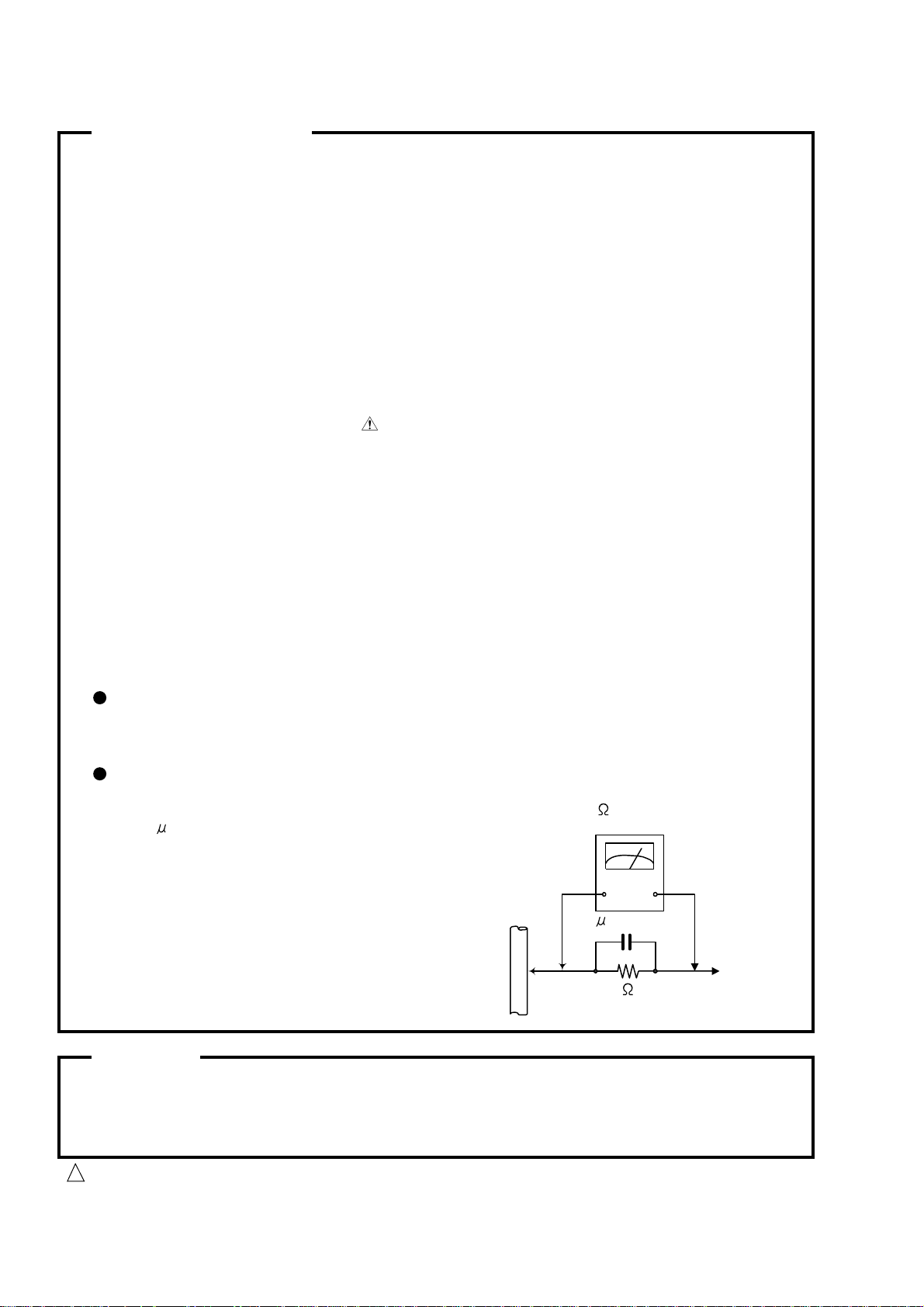
Alternate check method
Plug the AC line cord directly into the AC outlet. Use an AC voltmeter having 1,000 ohms
per volt or more sensitivity in the following manner. Connect a 1,500 10W resistor paralleled by
a 0.15 F AC-type capacitor between an exposed
metal part and a known good earth ground.
Measure the AC voltage across the resistor with the
AC voltmeter.
Move the resistor connection to each exposed metal
part, par ticularly any exposed metal part having a
return path to the chassis, and measure the AC
voltage across the resistor. Now, reverse the plug in
the AC outlet and repeat each measurement. Voltage
measured any must not exceed 0.75 V AC (r.m.s.).
This corresponds to 0.5 mA AC (r.m.s.).
0.15 F AC TYPE
1500 10W
Good earth ground
AC VOLTMETER
(Having 1000
ohms/volts,
or more sensitivity)
Place this
probe on
each exposed
metal part.
Warning
1. This equipment has been designed and manufactured to meet international safety standards.
2. It is the legal responsibility of the repairer to ensure that these safety standards are maintained.
3. Repairs must be made in accordance with the relevant safety standards.
4. It is essential that safety critical components are replaced by approved parts.
5. If mains voltage selector is provided, check setting for local voltage.
Burrs formed during molding may be left over on some parts of the chassis. Therefore,
pay attention to such burrs in the case of preforming repair of this system.
1-2
CAUTION
!
Page 3
RV-B550BU
I
mportance administering point on the safety
Note : It's means "J" for U.S.A. and Canada market model.
RV-B550J ONLY
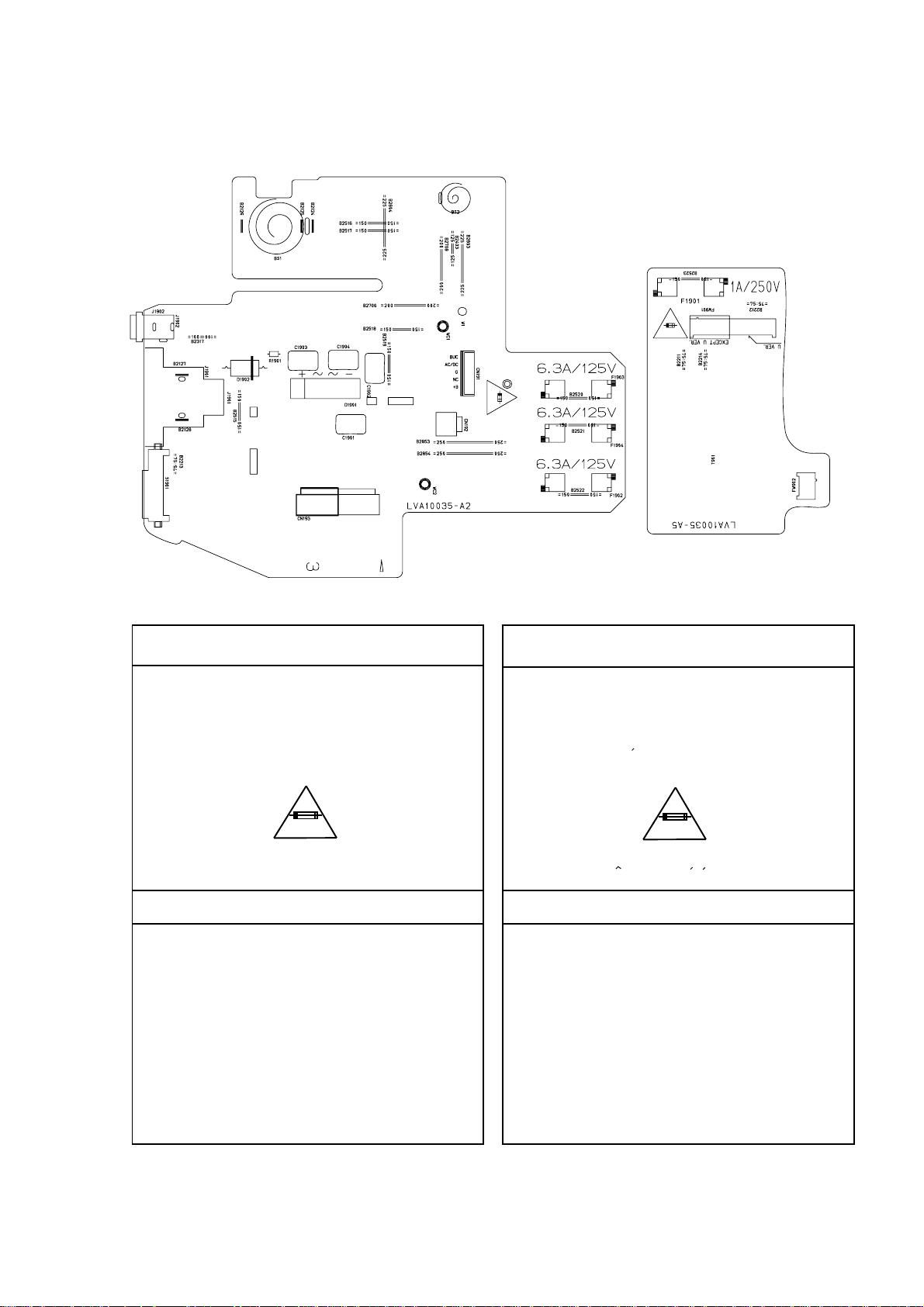
Full Fuse Replacement Marking
Graphic symbol mark
(This symbol means fast blow type fuse.)
should be read as follows ;
FUSE CAUTION
FOR CONTINUED PROTECTION AGAINST RISK
OF FIRE, REPLACE ONLY WITH SAME TYPE
AND RATING OF FUSES ;
F1901 : 1.0-A, 250-V
F1902 : 6.3-A, 125-V
F1903 : 6.3-A, 125-V
F1904 : 6.3-A, 125-V
RV-B550J SEULEMENT
Marquage Pour Le Remplacement
Complet De Fusible
Le symbole graphique (Ce symbole signifie
fusible de type a fusion rapide.)
doit etre interprete comme suit ;
PRECAUTIONS SUR LES FUSIBLES
POUR UNE PROTECTION CONTINUE CONTRE
DES RISQUES D'INCENDIE, REMPLACER
SEULEMENT PAR UN FUSIBLE DU MEME TYPE ;
F1901 : 1.0-A, 250-V
F1902 : 6.3-A, 125-V
F1903 : 6.3-A, 125-V
F1904 : 6.3-A, 125-V
1-3
Page 4
RV-B550BU
Important for laser products
1.CLASS 1 LASER PRODUCT
2.DANGER : Invisible laser radiation when open and inter
lock failed or defeated. Avoid direct exposure to beam.
3.CAUTION : There are no serviceable parts inside the
Laser Unit. Do not disassemble the Laser Unit. Replace
the complete Laser Unit if it malfunctions.
4.CAUTION : The compact disc player uses invisible
laserradiation and is equipped with safety switches
whichprevent emission of radiation when the drawer is
open and the safety interlocks have failed or are de
feated. It is dangerous to defeat the safety switches.
VARNING : Osynlig laserstrålning är denna del är öppnad
och spårren är urkopplad. Betrakta ej strålen.
VARO : Avattaessa ja suojalukitus ohitettaessa olet
alttiina näkymättömälle lasersäteilylle.Älä katso
säteeseen.
REPRODUCTION AND POSITION OF LABELS
5.CAUTION : If safety switches malfunction, the laser is able
to function.
6.CAUTION : Use of controls, adjustments or performance of
procedures other than those specified herein may result in
hazardous radiation exposure.
CAUTION
!
Please use enough caution not to
see the beam directly or touch it
in case of an adjustment or operation
check.
ADVARSEL : Usynlig laserstråling ved åbning , når
sikkerhedsafbrydere er ude af funktion. Undgå
udsættelse for stråling.
ADVARSEL : Usynlig laserstråling ved åpning,når
sikkerhetsbryteren er avslott. unngå utsettelse
for stråling.
CLASS 1
LASER PRODUCT
WARNING LABEL
DANGER : Invisibie laser radiation
when open and interlock or
defeated.
AVOID DIRECT EXPOSURE TO
BEAM (e)
VARNING : Osynlig laserstrålning är
denna del är öppnad och spårren är
urkopplad. Betrakta ej strålen. (s)
VARO : Avattaessa ja suojalukitus
ohitettaessa olet alttiina
näkymättömälle lasersäteilylle.Älä
katso säteeseen. (d)
ADVARSEL :Usynlig laserstråling
ved åbning , når
sikkerhedsafbrydere er ude af
funktion. Undgå udsættelse for
stråling. (f)
1-4
Page 5
RV-B550BU
Preventing static electricity
1. Grounding to prevent damage by static electricity
Electrostatic discharge (ESD), which occurs when static electricity stored in the body, fabric, etc. is discharged,
can destroy the laser diode in the traverse unit (optical pickup). Take care to prevent this when performing repairs.
2. About the earth processing for the destruction prevention by static electricity
In the equipment which uses optical pick-up (laser diode), optical pick-up is destroyed by the static electricity of
the work environment.
Be careful to use proper grounding in the area where repairs are being performed.
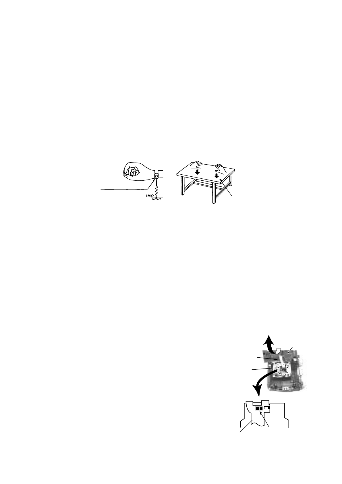
2-1 Ground the workbench
Ground the workbench by laying conductive material (such as a conductive sheet) or an iron plate over
it before placing the traverse unit (optical pickup) on it.
2-2 Ground yourself
Use an anti-static wrist strap to release any static electricity built up in your body.
(caption)
Anti-static wrist strap
Conductive material
(conductive sheet) or iron plate
3. Handling the optical pickup
1. In order to maintain quality during transport and before installation, both sides of the laser diode on the
replacement optical pickup are shorted. After replacement, return the shorted parts to their original condition.
(Refer to the text.)
2. Do not use a tester to check the condition of the laser diode in the optical pickup. The tester's internal power
source can easily destroy the laser diode.
4. Handling the traverse unit (optical pickup)
1. Do not subject the traverse unit (optical pickup) to strong shocks, as it is a sensitive, complex unit.
2. Cut off the shorted part of the flexible cable using nippers, etc. after replacing the optical pickup. For specific
details, refer to the replacement procedure in the text. Remove the anti-static pin when replacing the traverse
unit. Be careful not to take too long a time when attaching it to the connector.
3. Handle the flexible cable carefully as it may break when subjected to strong force.
4. It is not possible to adjust the semi-fixed resistor that adjusts the laser power. Do not turn it
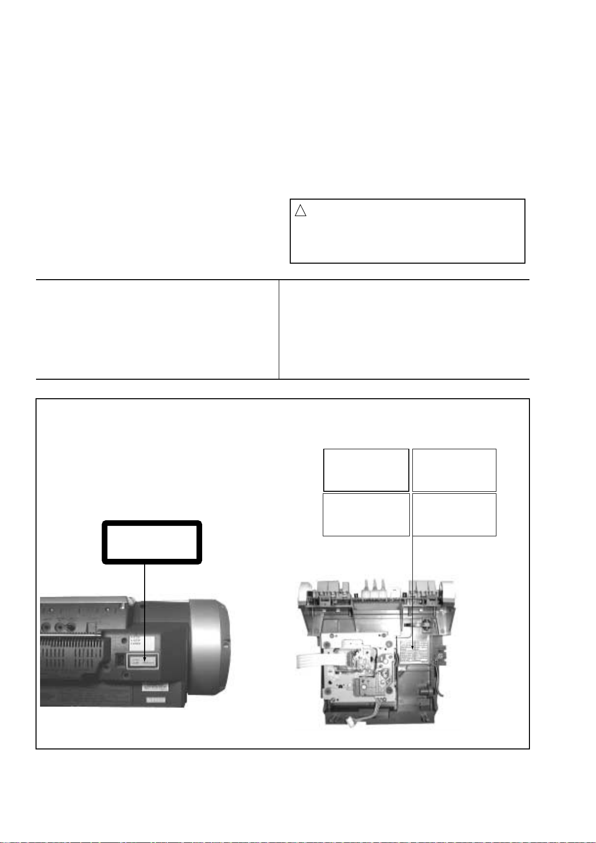
Attention when CD mecanism assembly is decomposed
*Please refer to "Disassembly method" in the text for pick-up and how to
detach the CD mechanism.
1. Remove CD mechanism assembly.
2. Remove the four screws on the microcomputer board.
3. Disconnect the connector CN907 and CN602 on the microcomputer board.
4. The microcomputer board is put up as shown in Fig.1.
5. Solder is put up before the card wire is removed from connector CN601
on the maicroconputer board as shown in Fig. 2.
(When the wire is removed without putting up solder, the CD pick-up
assembly might destroy.)
6. Please remove solder after connecting the card wire with CN601 when
you install picking up in the substrate.
Card wire
CD changer
mechanism
assembly
Flexible cable
Soldering
Fig.2
Microcomputer
board
Fig.1
1-5
Page 6
RV-B550BU
Disassembly method
<Main Body>
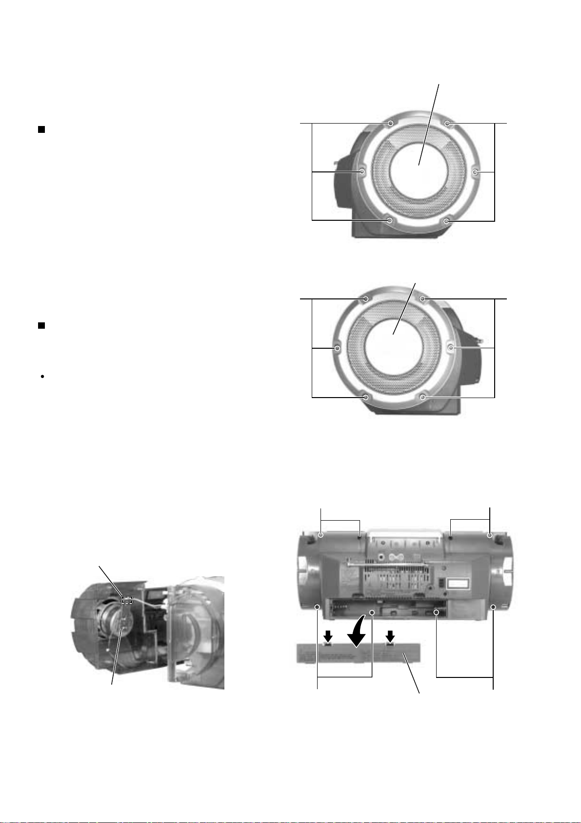
Removing the side grilles
(See Fig.1 and 2)
1.
Remove the six screws A attaching the side grille on
the left side of the body and pull out the side grille
from the body.
2.
Similarly, remove the side grille on the right side.
Removing the front cabinet assembl y and
the rear cabinet assembly (See Fig.3
and 3a)
A
A
Side grille (left)
A
Fig.1
Side grille (right)
A
Prior to performing the following procedure, remove
the right and left side grilles.
1.
Remove the battery cover on the back of the body.
2.
Remove the eight screws B on the back of the body
and detach the front cabinet assembly and the rear
cabinet assembly. Disconnect the connector CN904
on the LED
Attention:
(Illumination) board.
When reassembling, make sure that
connector CN633 on the rear cabinet is
connected to the speaker terminal on the
front cabinet.
CN904
B
Push Push
Fig.2
B
1-6
LED (Illumination) board
Fig.3a
B
Battery cover
Fig.3
B
Page 7
RV-B550BU
The CD unit assembly cannot be removed if the
cassette mechanism assembly has not been
removed.
Prior to performing the following procedure, remove
the right and left side grilles, the front cabinet
assembly and the cassette mechanism assembly.
Remove the cassette chassis (See Fig.6).
Disconnect the card wires from connector CN631
and CN632 on the amplifier board.
Disconnect the card wires from connector CN403 on
the microcomputer board.
Remove the two screws D attaching the CD
mechanism assembly on the back of the rear cabinet
(See Fig.8).
Pull out the CD unit assembly toward the front.
1.
2.
3.
4.
5.
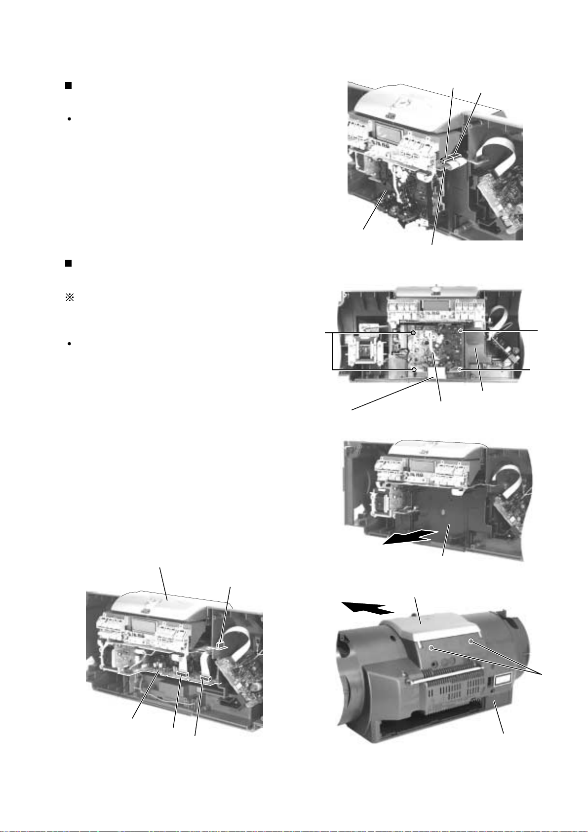
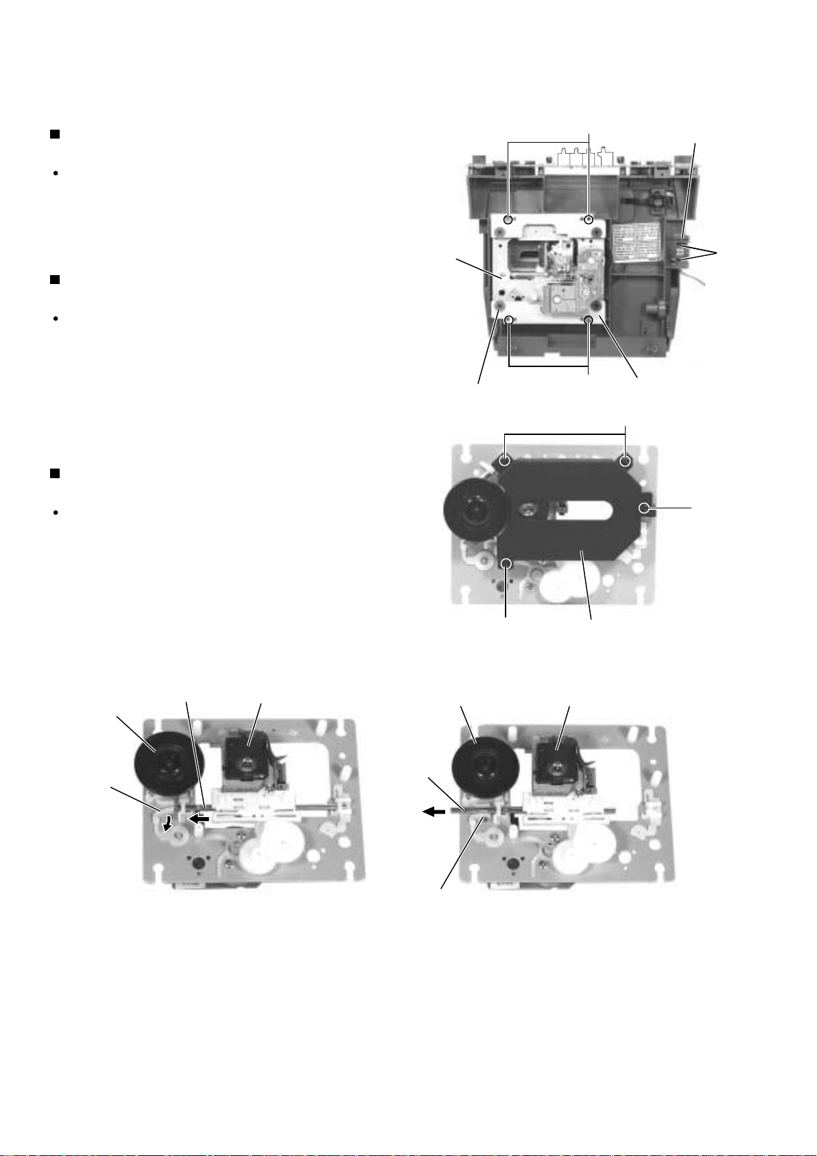
Removing the CD unit assembly
(See Fig.6 to 8)
Prior to performing the following procedure, remove
the right and left side grilles and the front cabinet
assembly.
Disconnect the card wires from connector CN405
and CN406 on the microcomputer board located on
the underside of the CD unit of the rear cabinet
assembly.
Remove the four screws C attaching head shield and
the cassette mechanism assembly.
1.
2.
Removing the cassette mechanism
assembly (See Fig.4 and 5)
Fig.4
Fig.5
CN406
CN405
Microcomputer board
Cassette mechanism
assembly
Cassette chassis
Cassette mechanism assembly
C
C
CD unit assembly
CN403
Microcomputer board
CN632
CN631
amplifier board
Cassette chassis
Rear cabinet
D
CD unit assembly
Fig.6
Fig.8Fig.7
Head shield
1-7
Page 8
RV-B550BU
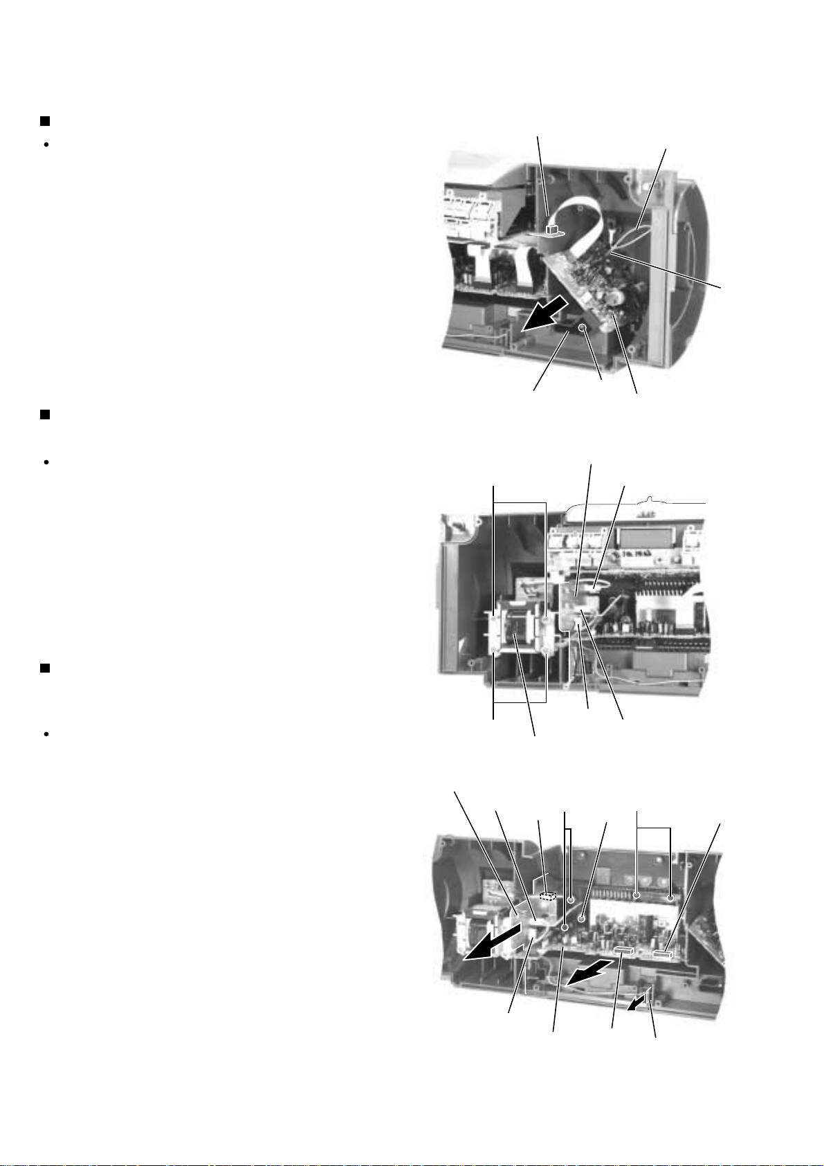
Removing the tuner board (See Fig.9)
Prior to performing the following procedure, remove
the right and left side grilles, the front cabinet
assembly.
1.
Disconnect the card wire from connector CN403 on
the microcomputer board.
2.
Remove the screw E attaching the tuner board
holder and pull out the tuner board holder together
with the tuner board. Disconnect the antenna wire
from TP1.
Remove the power transformer assemb ly
(See Fig.10)
Prior to performing the following procedure, remove
the right and left side grilles, the front cabinet assembly,
the cassette mechanism assembly and the cassette
chassis.
Microcomputer board
CN403
Tuner board holder
Power supply board
F
Fig.9
Antenna wire
E
Tuner board
CN193
TP1
1.
Disconnect the harness from connector CN192 and
CN193 on the power supply board respectively.
2.
Remove the four screws F attaching the power
transformer assembly.
Remove the amplifier board, the power
supply board and the battery board
(See Fig.11)
Prior to performing the following procedure, remove
the right and left side grilles, the front cabinet
assembly, the cassette mechanism assembly, the
cassette chassis and the CD unit assembly.
1.
Disconnect the 5pin harness from connector CN191
on the power supply board.
2.
Remove the two screws G and the one screw H
attaching the amplifier board.
3.
Disconnect the harness from connector CN192 and
CN193 on the power supply board respectively.
F
Power supply board
CN192
CN191
CN192
Power transformer assembly
Fig.10
CN193
I
G
H
CN631
4.
Remove the two screws I attaching the power supply
board.
5.
Pull out the battery board.
1-8
CN191
Amplifier board
CN631
Fig.11
Battery board
Page 9
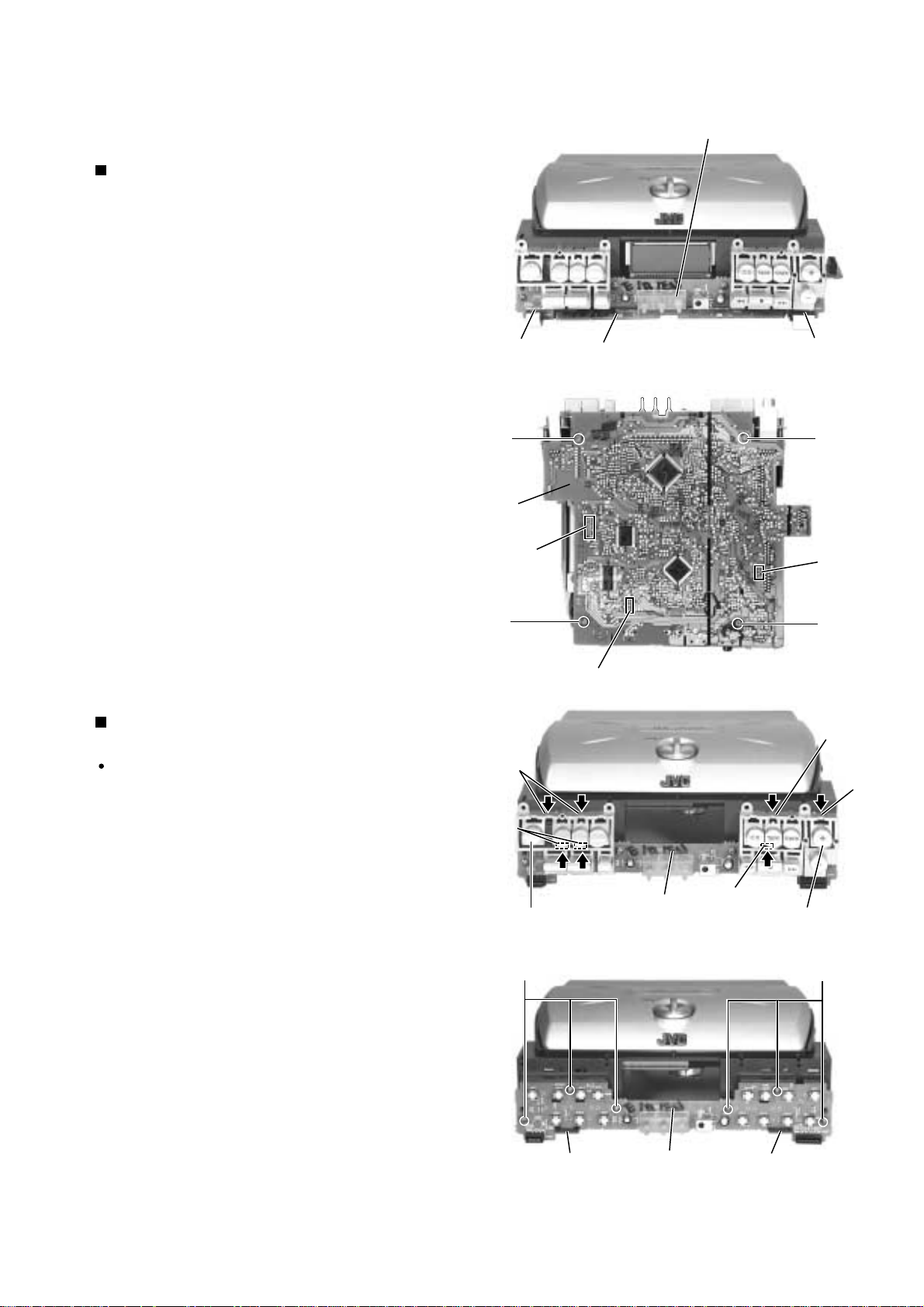
RV-B550BU
Disconnect the card wire from connector CN251 and
CN252 on the key switch board on the front side of
the CD unit assembly.
Remove the f our screws J attaching the microcomputer
board on the underside of the CD unit assembly.
Disconnect the card wire or the harness from
connector CN601, CN602 and CN907 on the
microcomputer board respectively.
1.
2.
3.
Removing the microcomputer board
(See Fig.12 and 13)
Prior to performing the following procedure, remove
the microcomputer board.
Release the four tabs a fixing the right and left
function buttons and the three tabs b by the key
switch board.
Push tabs a and b in the directions of the arrows
carefully not to damage the function buttons
Remove the six screws K attaching the key switch
board.
Pull out the key switch board from two tabs c.
1.
2.
3.
Removing the key switch board
(See Fig.14 and 15)
<CD unit assembly>
Fig.15
Fig.14
Fig.12
PushPush
CN252
CN251
Microcomputer board
Microcomputer board
J
J
J
J
CN602
CN601
CN907
Push
PushPushPush
PushPushPush
Push
a
b
a
b
Key switch board
Function switch buttons
(power)
Function switch buttons
(volume)
Key switch board
c
c
KK
a
Key switch board
PushPushPush
Fig.13
1-9
Page 10
RV-B550BU
Removing the CD door switch board
(See Fig.16)
Prior to performing the following procedure, remove
the microcomputer board.
1.
Release the two tabs d fixing the CD door switch
board on the back of the CD unit assembly.
Removing the CD mechanism assembly
(See Fig.16)
Prior to performing the following procedure, remove
the microcomputer board.
1.
Remove the f our scre ws L attaching the CD mechanism
holder on the back of the CD unit assembly.
2.
Remove the CD mechanism holder, the CD cushion
and the CD mechanism assembly respectively.
Removing the pickup assembly
(See Fig.17 to 19)
Prior to performing the following procedure, remove
the CD mechanism assembly.
CD mechanism
Assembly
CD cushion
L
L
CD door switch
board
CD mechanism holder
M
d
Fig.16
M
1.
Remove the f our screws M attaching the pickup cover.
2.
Push the shaft stopper by the turn table in the direction
of the arrow and pull out the shaft. The pickup assembly
comes off.
Turn table
Shaft
Shaft stopper
Pickup assembly
Fig.18
Turn table
Shaft
Shaft stopper
M
Pickup assembly
Pickup cover
Fig.17
Fig.19
1-10
Page 11
RV-B550BU
Prior to performing the following procedure, remove
the front cabinet assembly and the rear cabinet
assembly.
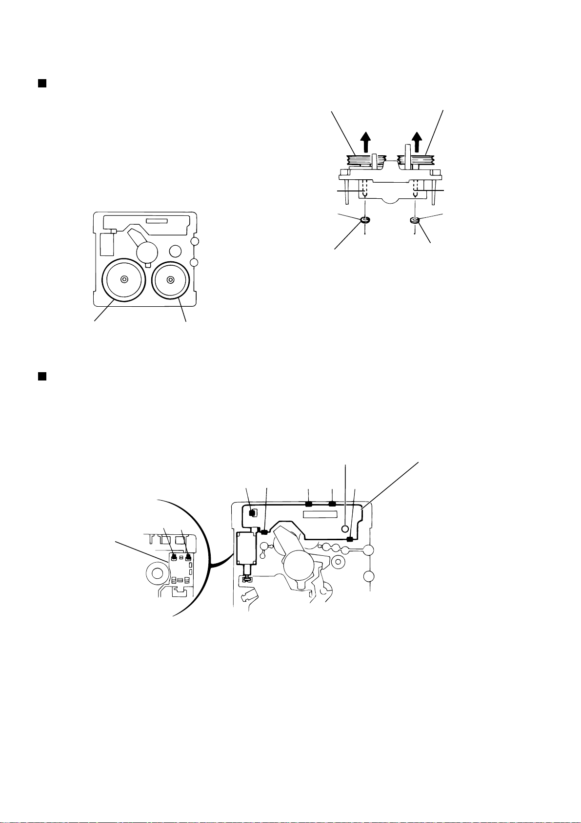
Remove the eight screws P attaching the right and
left speakers on the inside of the front cabinet assembly.
Remove the screw Q attaching the speaker terminal.
1.
2.
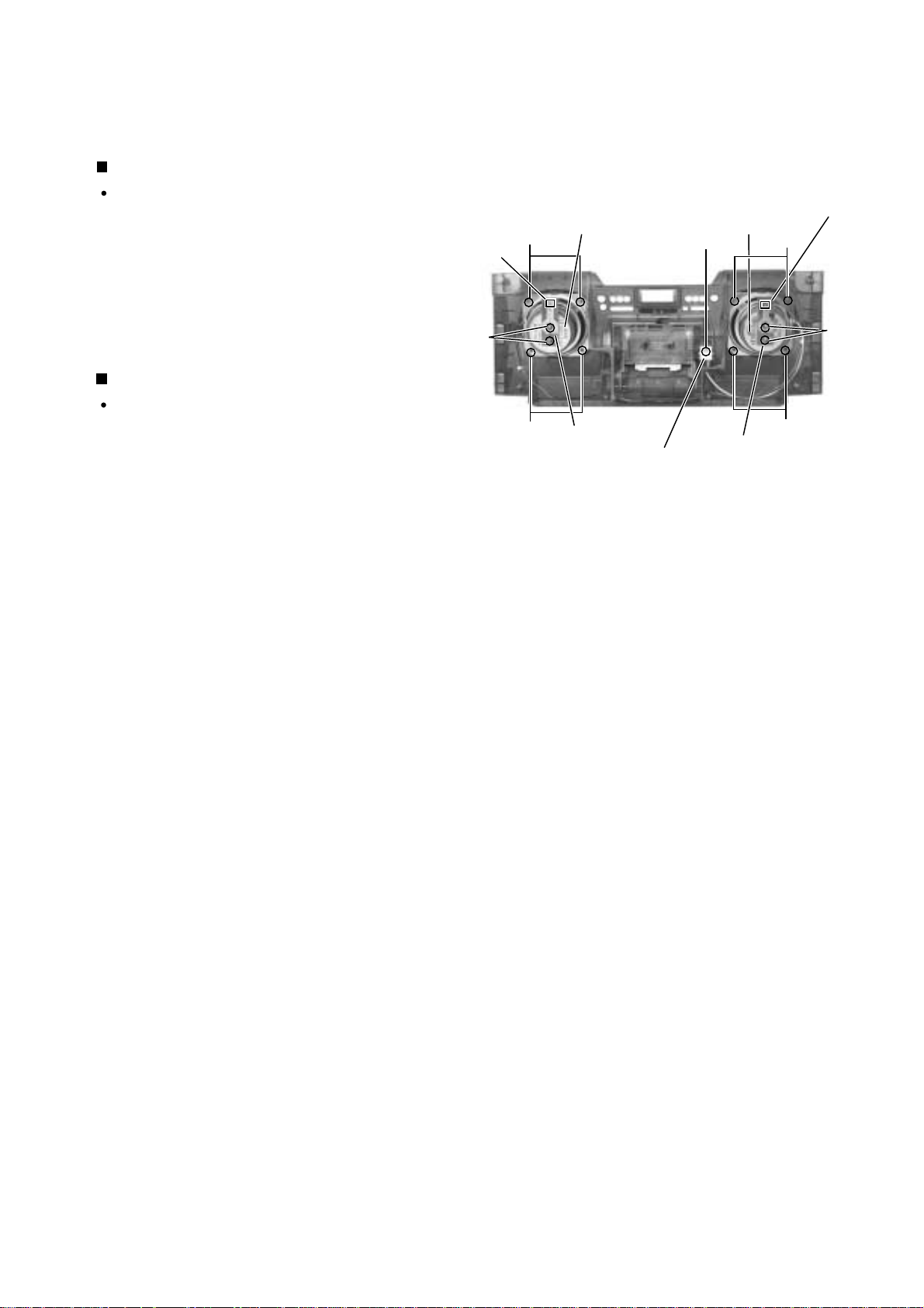
Removing the speakers (See Fig.20)
<Front Cabinet Assembly>
Prior to performing the following procedure, remove
the front cabinet assembly and the rear cabinet
assembly.
Remove the two screws N and two screws O
attaching the LED boards on the speaker .
Disconnect the harness from connector FW251 and
FW261.
1.
2.
Removing the LED boards (See Fig.20)
Fig.20
P
P
P
Q
Speaker terminal
Speaker Speaker
LED board
LED board
O
N
P
FW261
FW251
1-11
Page 12
RV-B550BU
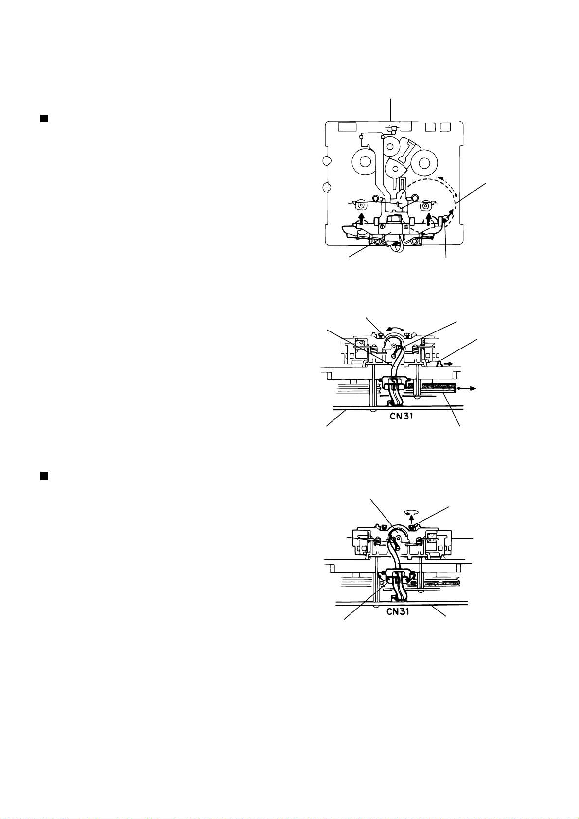
<<Cassette mechanism section>>
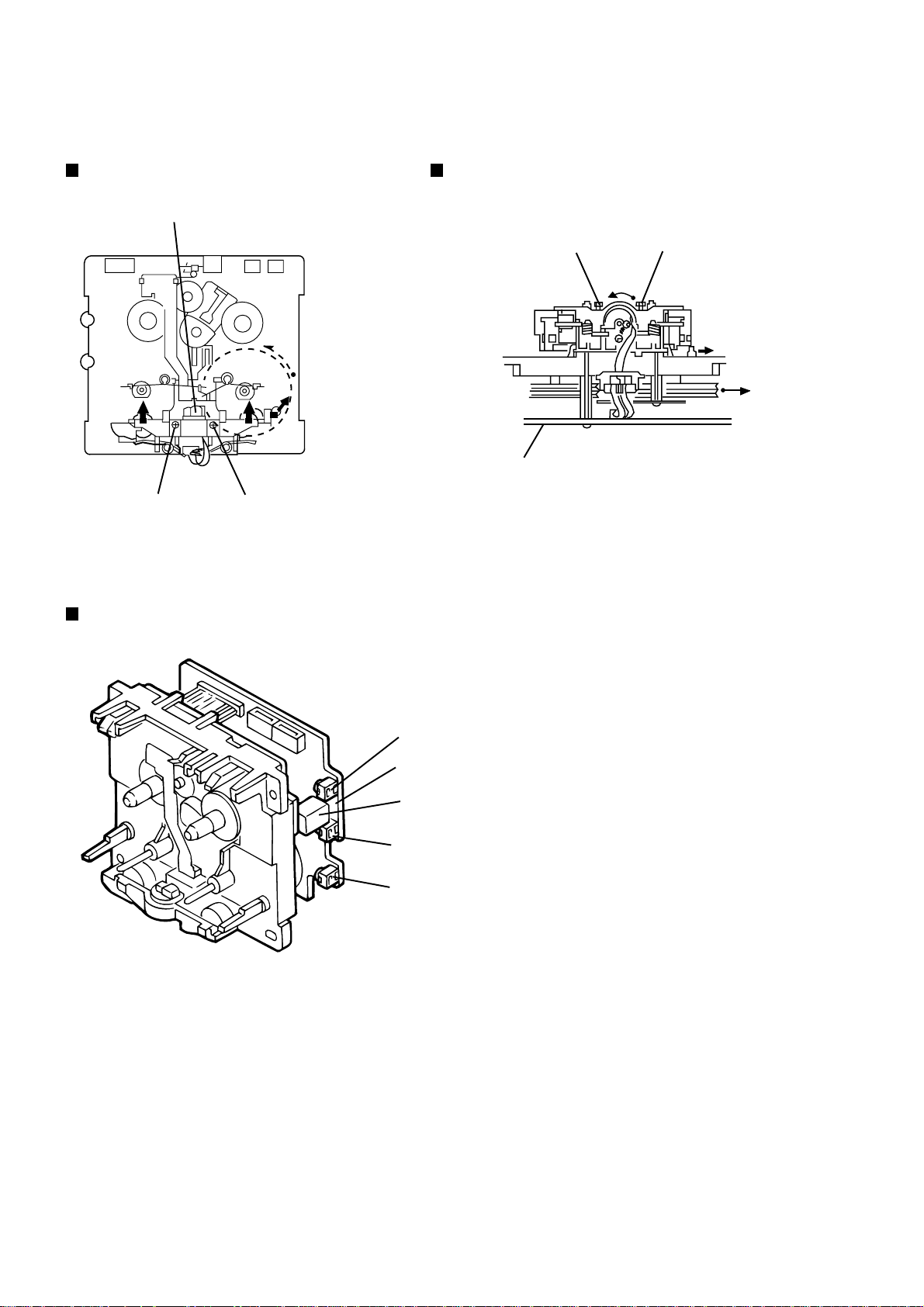
Removing the playback/recording & eraser
head ( See Figs. 1 and 2 )
1. While shifting the trigger arms seen on the right
side of the head mount in the arrow direction,
turn the flywheel R in counterclockwise direction
until the head mount has gone out with a click
(See Fig. 1).
2. When the flywheel R is rotated in counterclockwise
direction, the playback/recording & eraser head
will be turned in counterclockwise direction from the
position in Fig. 2 to that in Fig. 3.
3. At this position, disconnect the flexible P.C. board
(outgoing from the playback/recording & eraser head)
from the connector CN31 on the head amplifier &
mechanism control P.C. board.
4. After dismounting the FPC holder, remove the flexible
P.C. board.
5. Remove the flexible P.C. board from the chassis base.
6. Remove the spring a from behind the playback/recording
& eraser head.
7. Loosen the reversing azimuth screw retaining the playback
/recording & eraser head.
8. Take out the playback/recording & eraser head from the
front of the head mount.
9. The playback/recoring & eraser head should also be
removed similarly according to Steps 1 ~ 8 above.
Cassette mechanism
Fig. 1
Playback/recording &
eraser head
Frexible
board
Head amplifier & mechanism
control P.C. board
Flywheel R
Trigger armHead mount
Spring a
Trigger arm
Flywheel R
Reassembling the playback/recording
& eraser head
1. Reassemble the playback head from the front of the head
mount to the position as shown in Fig. 3.
2. Fix the reversing azimuth screw.
3. Set the spring a from behind the Playback/Recording &
Eraser head.
4. Attach the flexible P.C. board to the chassis base, and fix
it with the FPC holder as shown in Fig. 3.
5. The playback/recording & eraser head should also be
reassembled similarly to Step 1 ~ 4 above.
Playback/recording &
eraser head
Spring "a"
FPC holder
Fig. 2
Reversing azimuth
screw
Head
mount
Frexible
board
Head amplifier &
mechanis control
P.C. board
Fig. 3
1-12
Page 13
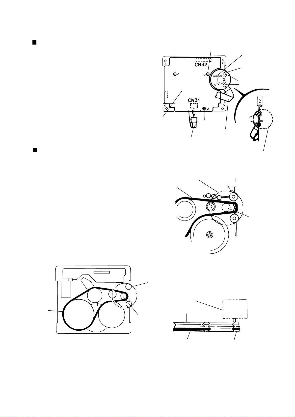
RV-B550BU
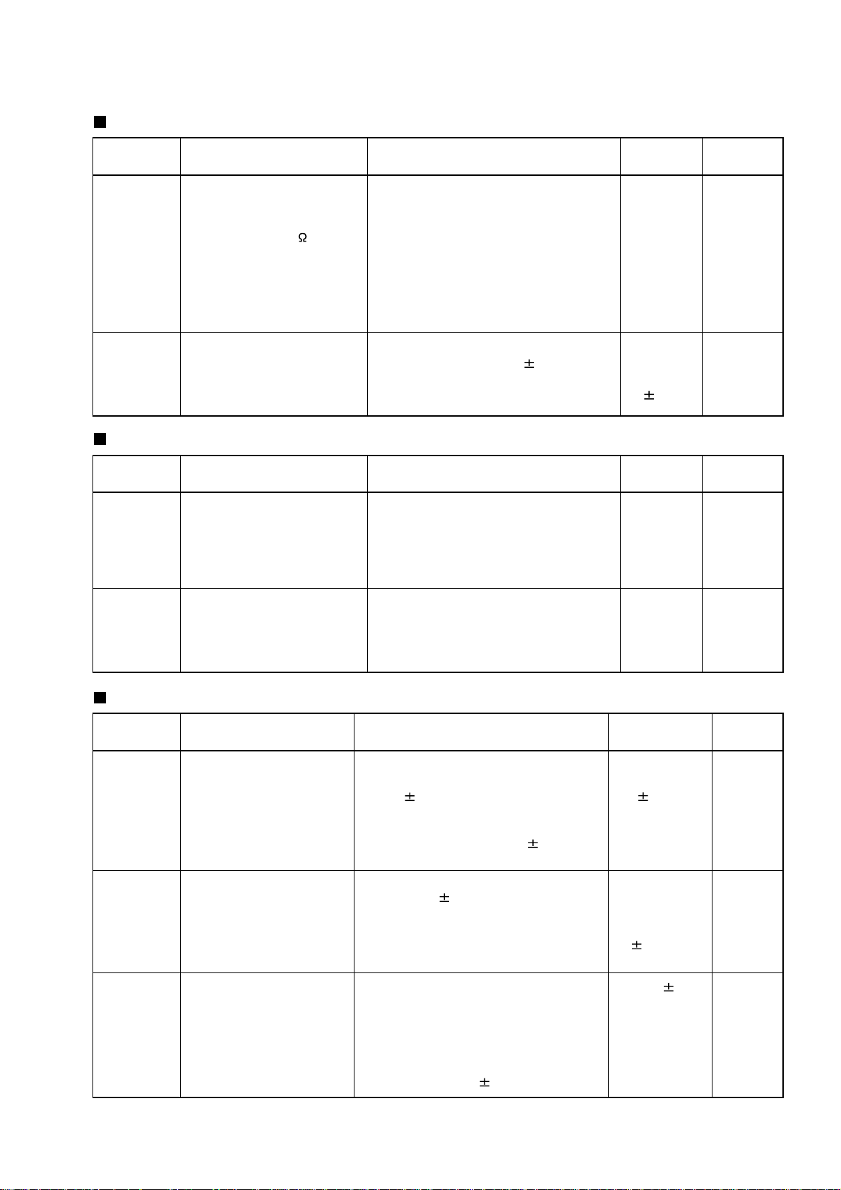
Removing the head amplifier & mechanism
control P.C. board (See Fig. 4)
1. Remove the cassette mechanism assembly.
2. After turning over th cassette mechanism assembly,
remove the three screws A retaining the head
amplifier & mechanism control P.C. board.
3. Disconnect the connector CN32 on the P.C. board
including the connector CN 1 on the reel pulse P.C.
board.
4. When necessary, remove the 4 pin parallel wire
soldered to the main motor.
Head amplifier &
mechanism control
P.C. board
Removing the main motor assembly
(See Fig. 4~6)
1. Remove the two screws B retaining the main
motor assembly (See Fig. 4, 4a).
2. While raising the main motor, remove the capstan
belt from the motor pulley (See Fig. 4a).
Caution 1: Be sure to handle the capstan belt so
carefully that this belt will not be
stained by grease and other foreign
matter. Moreover, this belt should be
hanged while referring to the capstan
belt hanging method in Fig. 5, 6.
A
Flexible P.C. board
Capstan belt
A
Fig. 4
Main motor
assembly
A
Belt
Main motor
assembly
B
B
4pin parallel wire
Main
moteor
assembly
Motor
pulley
Capstan
belt
Fig. 5
Mechanism motor
assembly
Motor
pulley
Fig. 4a
Main motor
assembly
Flywheel
Motor pulleyCapstan belt
Fig. 6
1-13
Page 14
RV-B550BU
Removing the flywheel
(See Figs. 7 and 8)
1. Remove the head amplifier & mechanism control
P.C. board.
2. Remove the main motor assembly.
3. After turning over the cassette mechanism,
remove the slit washers b and c fixing the capstan
shafts R and L, and pull out the flywheel R and L
respectively from behind the cassette mechanism.
Flywheel R Flywheel L
Capstan shaft R Capstan shaft L
Flywheel R Flywheel L
Fig. 8
Removing the reel pulse P.C. board and solenoid
(See Fig. 9)
1. Remove the five pawls d~h and screw C reataining the reel pulse
P.C. board.
2. From the surface of the reel pulse P.C. board parts, remove
the two pawls i and j retaining the solenoid.
hd
e
C
Slit
washer
f
b
Slit
washer
Fig.7
C
g
Reel pulse P.C. board
1-14
Solenoid
j
i
Fig. 9
Page 15

Adjustment method
RV-B550BU
Measuring devices necessary for adjustment
1. Low-frequency oscillator
It must have the ability to output 600ohm from 0 dBs
at an oscillation frequency of 20 Hz 50 Hz.
2.Attenuator impedance: 600ohm
3.Electronic voltmeter
Tuner section
Voltage input to the tuner .......................... +B: DC 5.7 V
VT: DC 12 V
Standard measuring output ...... 26.1 mV (0.28 V) /3ohm
Input locations ..................... AM: standard loop antenna
FM: TP1 (hot) and TP2 (GND)
Standard settings for measuring volume
4.Distortion meter
5.Frequency counter
6.Wow and flutter meter
7.Test tapes
VT-712: tape speed and rotational distortion (3 kHz)
VT-724: standard level (1 kHz)
VT-703: head angle adjustment (10 kHz),
or use VT-73
VT-739: reproduction of frequency characteristics
(1 kHz, 63 Hz, 10 kHz)
8.Blank tape
Type I : AC-225 (TDK-AD)
Type II : AC-514 (TDK-SA)
9.Torque gauge: Tension gauge for playback,
fast-forward and rewind.
FWD (TW211A), REW (TW212A)
and FF/REW (TW2231A)
Sound ..................................................................... OFF
Effective hyper bass ............................................... OFF
Volume adjustment ........................................... VOL. 23
Precautions for measuring
1.Input 30 pF and 33 kohm to the IF sweeper output
2.Lower the output level of the IF sweeper as much as
3.The IF sweeper needs no adjustment as it is a fixed
4.It is not necessary to perform any kind of adjustment
and 0.082 F and 100 kohm to the sweeper input,
respectively.
possible in the adjustable range.
component.
on the MPX, as a ceramic oscillator is used for
measuring.
Specifications for measurement
Power supply voltage ................... AC 100 V (50/60 Hz)
Standard output ........................ Speaker: 0.775V/4ohm
Headphone:0.245V/32ohm
Standard frequency and input level
................... 1 kHz: AUX: -8 dBs
Input level for reproduction of recording characteristics
................... AUX: -28 dBs
Measuring output terminal ................... Speaker: CN633
Load resistance .................................................... 4ohm
Radio input signal
AM frequency ..................................................... 400 Hz
Degree of modulation in AM band .......................... 30%
FM frequency ...................................................... 400 Hz
Frequency deviation in FM band ..................... 22.5 kHz
5.FM tracking adjustment is not necessary as a fixed
coil is used.
6.The grounding circuit is separate from the input and
output. Therefore, be sure to connect to ground
carefully when measuring both the input and output
voltages simultaneously using 2 channels of the
electronic voltmeter.
7.The speaker's minus terminal cannot be connected to
ground when using a BTL format amplifier. Therefore,
do not connect any type of ground wire to this
terminal. The OTL format is used with this system.
8.Use a large wire to connect to the dummy impedance
generator when measuring the output.
9.Be sure to use a band pass filter (DV-12) when using
mixed tape.
1-15
Page 16
RV-B550BU
Location of parts to be adjusted
Cassette handling mechanism Cassette handling mechanism (reverse side)
Head for recording, playing
and erasing the tape
Head azimuth adjusting
screw (fast-forward)
CN31
Head azimuth adjusting
screw (rewind)
Head azimuth adjusting
adjusting screw (fast-forward)
Head azimuth
screw (rewind)
Location of parts to be adjusted
Head for recording,
playing and erasing the tape
VR37
Motor speed
TP
Bias oscillation frequency (wide pattern)
L301
Bias oscillation frequency
VR31
Lch recording frequency (bias adjustment)
VR32
Rch recording frequency (bias adjustment)
1-16
Page 17
Adjustment of cassette handling mechanism
RV-B550BU
Items Condition Method for adjustment
Confirmation
of head angle
Confirmation
of tape speed
Test tape: VT-703 (10 kHz)
Measuring output terminal:
Speaker terminal, speaker (R)
(Load resistance: 4 ),
headphone terminal
Test tape: VT-712 (3 kHz)
Measuring output terminal:
Headphone terminal
(1) Play back the VT-703 test tape.
(2) Adjust the head azimuth screws so
that the tape playback mechanism
records the maximum output level in
both the fast-forward and rewind
direction.
(3) In all cases, both the fast-forward and
rewind direction should be adjusted
using head azimuth screws.
Adjust VR37 so that the frequency
counter records 3,015 Hz 15 Hz when
playing back the end of the VT-712 test
tape (3 kHz) in the fast-forward direction.
and confirmation
Items to be confirmed and standard values
Items Condition Method for adjustment
Difference in
speed
between fastforward and
rewind
Test tape: VT-712 (3 kHz)
Measuring output terminal:
Speaker terminal, speaker (R)
(Load resistance: 4 ),
headphone terminal
The difference between fast-forward and
rewind should be less than 60 Hz on the
frequency counter when playing back the
beginning of the VT-712 test tape (3 kHz)
in both directions.
and confirmation
Standard
value
Maximum
output
Tape speed
of cassette
deck: 3,015
Hz 15 Hz
Standard
value
Less than 60 HzShould be
Parts to be
adjusted
Adjust the
head
azimuth
screws
when
changing
the head.
VR37
Parts to be
adjusted
confirmed
when
changing
the motor.
Wow and
flutter
Test tape: VT-712 (3 kHz)
Measuring output terminal:
Headphone terminal
Wow and flutter should be recorded at
less than 0.25% (WRMS) when playing
back the VT-712 test tape (3 kHz) in the
fast-forward direction.
Electronic performance
Items Condition Method for adjustment
Confirmation
of output
Confirmation
of
reproduction
of frequency
characteristics
Recording
bias
frequency
Measuring output terminal:
CN34-5 or 7-terminal
preamp base
Test tape: VT-724
Measuring output terminal:
Headphone terminal
Test tape: VT-739
Fast-forward or rewind
direction:
Test tape: TYPE II (AC-
514)
Measuring terminal: Bias
TP on the base
Confirm that the output from the CN34-5
or 7-terminal preamp base connector is 25 dBs 3 dB when playing back the VT724 test tape.
Reference value: The output from the
headphone terminal is -7 dB 4 dB.
Confirm that the 10 kHz reproduction
level is -1 dB 5 dB compared to the 1
kHz reproduction level when playing back
the VT-739 test tape.
Switch the bias (beat cut switch) between
1 and 2 to confirm that the frequency
changes. Load the test tape (AC-514 for
TYPE II) into the mechanism and preset
it to the record-pause mode.
Confirm that the bias TP frequency on
the base is 100 kHz 6 kHz.
and confirmation
Less than
0.25%
(WRMS)
Standard
value
Output of CN345 terminal: -25
dBs 3 dB
Difference
between Lch
and Rch: within
3 dB
Difference
between 10
kHz and 1 kHz
should be -1
dB 5 dB.
100 kHz 6 kHz
Parts to be
adjusted
1-17
Page 18
RV-B550BU
Standard values for confirmation of electronic performance
Items Condition Method for adjustment
Erasing
current
(standard
and
reference
value)
Adjustment of
reproduction
of frequency
characteristics
Fast-forward and
rewind direction:
Recording mode
AC-514 for TYPE II,
AC-225 for TYPE I
Measuring terminal:
Both erase head ter
minals
Standard frequencies:
1 kHz and 10 kHz
(REF: -20 dB)
Test tape: TYPE II:
AC-514
Measuring input
terminal: OSC IN
Load the test tape (AC-514 for TYPE II,
AC-225 for TYPE I) into the tape
playback mechanism and preset it to the
record-pause mode.
After setting it to the recording mode,
send 1 M in series to the erase head and
measure the erasing current from both
erase head terminals.
Load the test tape (AC-514 for TYPE II,
AC-225 for TYPE I) into the tape
playback mechanism and preset it to the
record-pause mode.
Input the standard value of -20 dB and
the standard frequencies of 1 kHz and 10
kHz repeatedly to the microphone input
from the transmitter in the recording
mode. Adjust VR31 for Lch and VR32 for
Rch so that the difference in level
between 10 kHz and 1 kHz is -1 dB 5
dB.
Repeat the above for TYPE I and confirm
that the difference in level is -XdB dB.
and confirmation
Standard
value
TYPE II: 110
mA
TYPE I: 75 mA
Difference in
output
between 1 kHz
and 10 kHz: -1
dB 5 dB
Parts to be
adjusted
Lch: VR31
Rch: VR32
(U version only)
Sensitivity of
reproduction
of
microphone
mixing
Microphone input
terminal: 1 kHz, -65 dB
Test tape: VT-724
Based on the reproduction level of the
VT-724 test tape, confirm that the
microphone level is 0 dBs 3 dB when a
1 kHz, 65 dBs signal is input.
(The mixing volume and sound volume
should be at maximum.)
0 dBs 3 dB
(Based on the
reproduction
level of the
VT-724)
1-18
Page 19
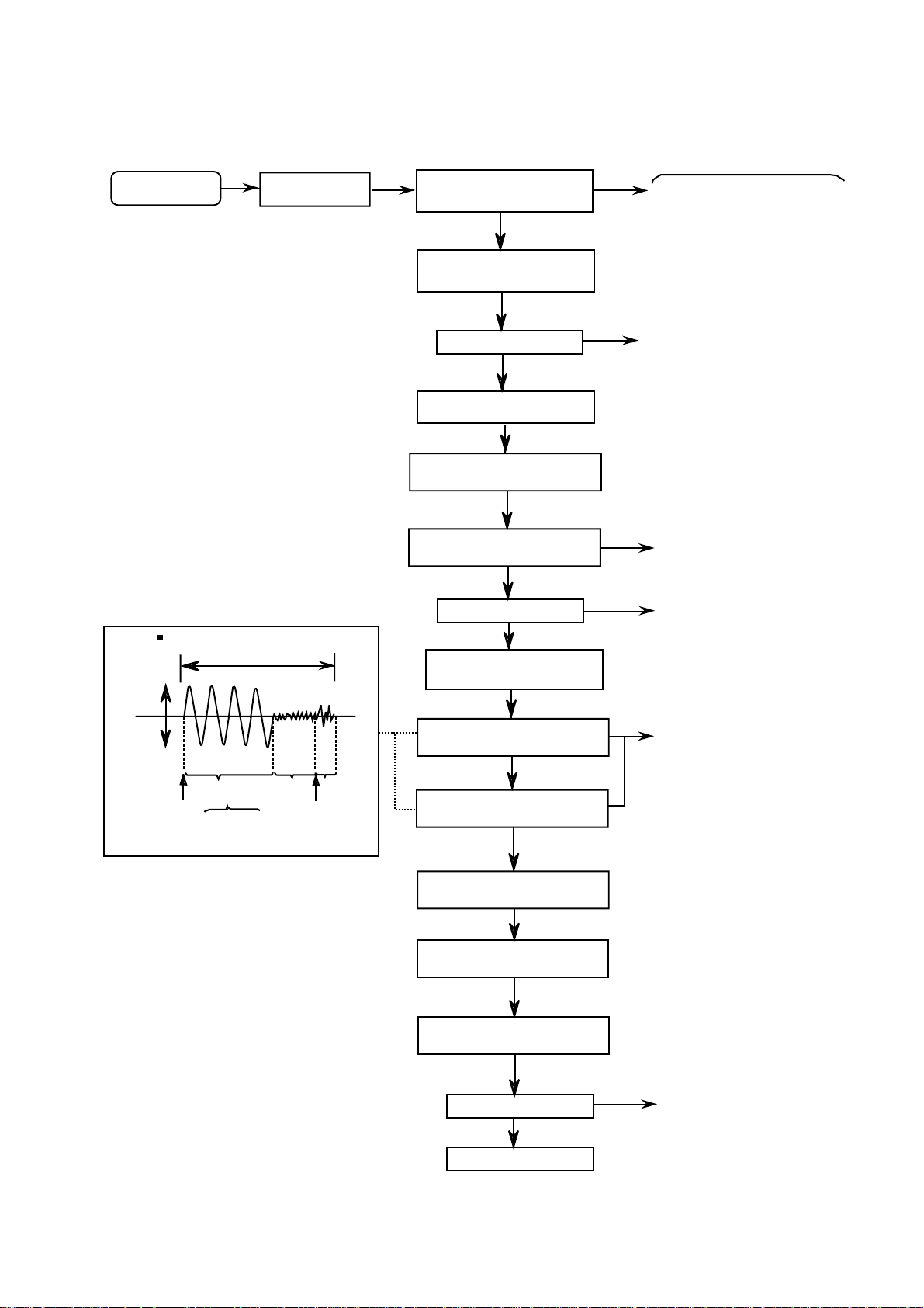
Flow of functional operation until TOC read
Slider turns REST
SW ON.
Automatic tuning
of TE offset
Laser ON
Detection of disc
Automatic measurement of
Focus A-curve amplitude
Automatic tuning of
Foucus offset
Disc is rotated
Focus servo ON
(Tracking servo ON)
Automatic tuning of
Tracking error balance
Automatic measurement of
Tracking error amplitude
Automatic tuning of
Focus error balance
Disc to be
braked to stop
Tracking
servo
on statas
Tracking
servo
off statas
Disc statas
to rotate
TOC reading
finishes
Automatic measurement
of TE amplitude and
automatic tuning of
TE balance
500mv/div
2ms/div
Fig.1
Approx.3sec
pin 25 of
IC601(TE)
Approx
1.8V
VREF
Tracking error waveform at TOC reading
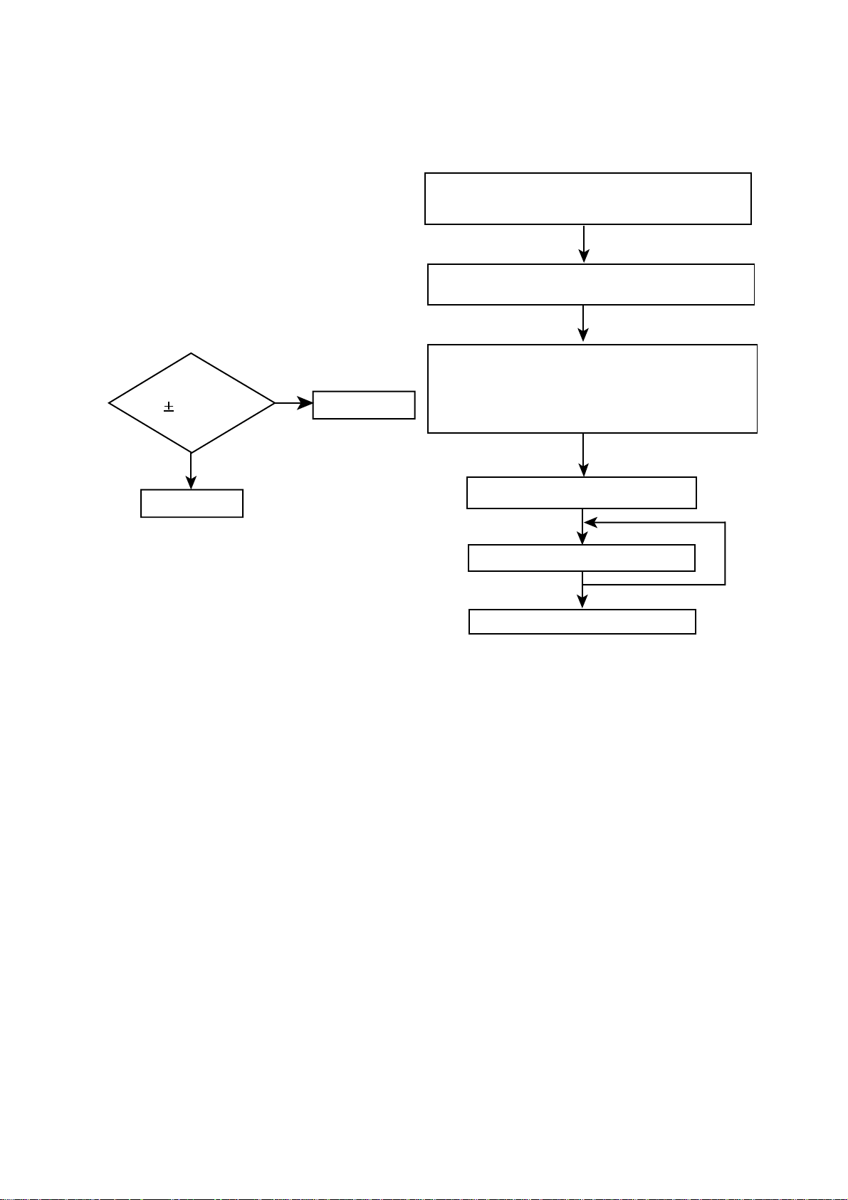
Power ON
Power Key
Confirm that the Focus error
S-cuve siganl at the pin27 of
IC601 is approx.2Vp-p
Confirm that the siganl from
pin24 IC603 is 0V as a
accelerated pulse during
approx.400ms.
Confirm the waveform of
the Tracking error signal
at the pin25 of IC601 (R612)
(See fig-1)
Automatic tuning of
Focus error gain
Automatic tuning of
Tracking error gain
TOC reading
Play a disc
Confirm the eys-pattern
at the lead of TP602
Check that the voltage at the pin 5
of CN602 (or pin 5 of IC901)
is 0V (a moment)?
Check Point
Check that the voltage at the
pin3 of IC601 + side is + 5V?
RV-B550BU
1-19
Page 20
RV-B550BU
Maintenance of laser pickup
(1) Cleaning the pick up lens
Befor you replace the pick up, please try to
clean the lens with a alcohol soaked cotton
swab.
(2) Life of the laser diode (Fig.1)
When the life of the laser diode has expired,
the following symptoms wil appear.
(1) The level of RF output (EFM output:ampli
tude of eye pattern) will below.
Is RF output
1.1 0.15Vp-p?
YES
O.K
NO
Replace it.
(Fig.1)
Replacement of laser pickup
Turn off the power switch and,disconnect the
power cord from the ac outlet.
Replace the pickup with a normal one.(Refer
to " Pickup Removal " on the previous page)
Plug the power cord in,and turn the power on.
At this time,check that the laser emits for
about 3seconds and the objective lens moves
up and down.
Note: Do not observe the laser beam directly.
Play a disc.
Check the eye-pattern at TP1.
(3) Semi-fixed resistor on the APC PC board
The semi-fixed resistor on the APC printed
circuit board which is attached to the pickup
is used to adjust the laser power.Since this
adjustment should be performed to match the
characteristics of the whole optical block,
do not touch the semi-fixed resistor.
If the laser power is lower than the specified
value,the laser diode is almost worn out, and
the laser pickup should be replaced.
If the semi-fixed resistor is adjusted while
the pickup is functioning normally,the laser
pickup may be damaged due to excessive current.
Finish.
1-20
Page 21
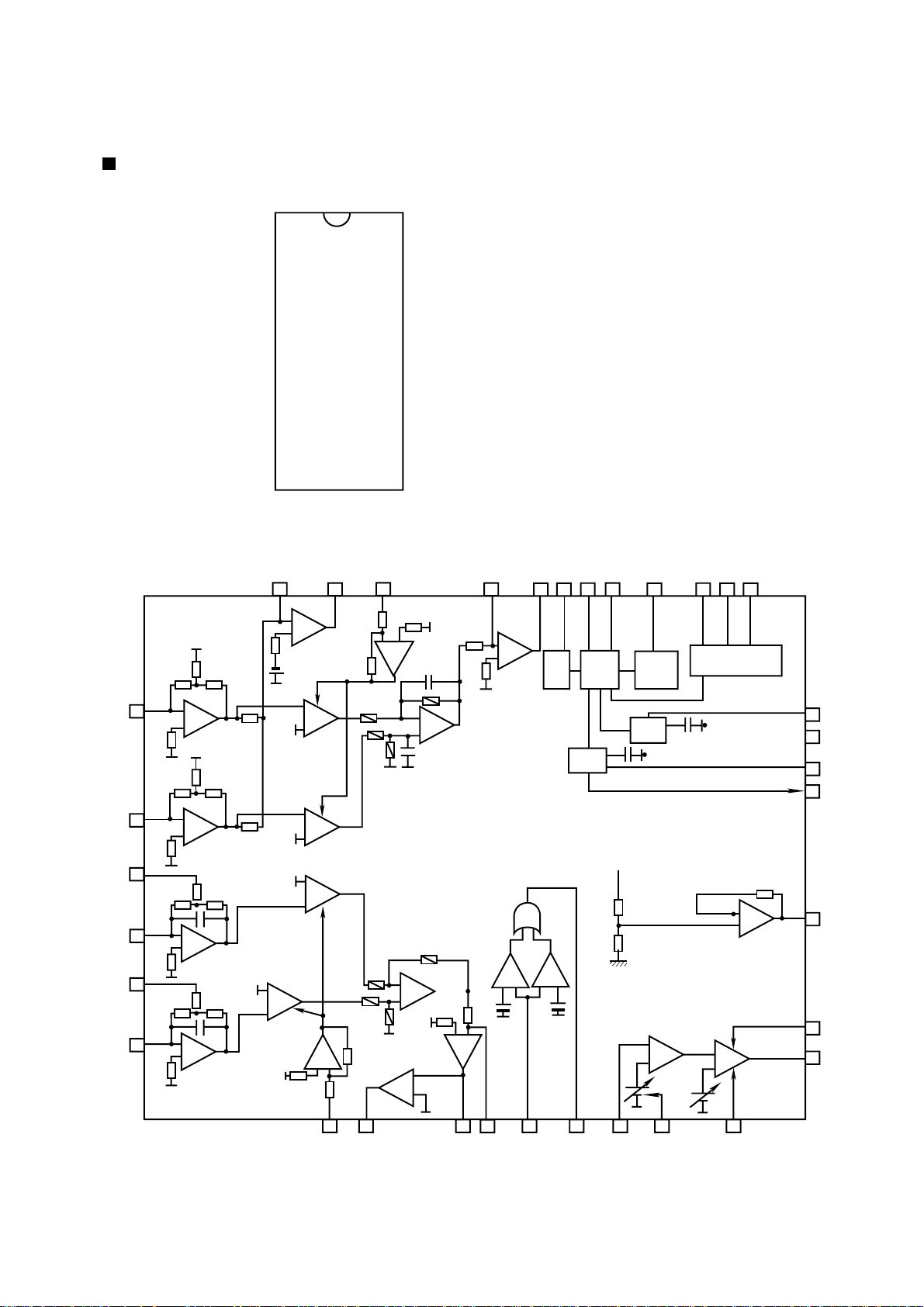
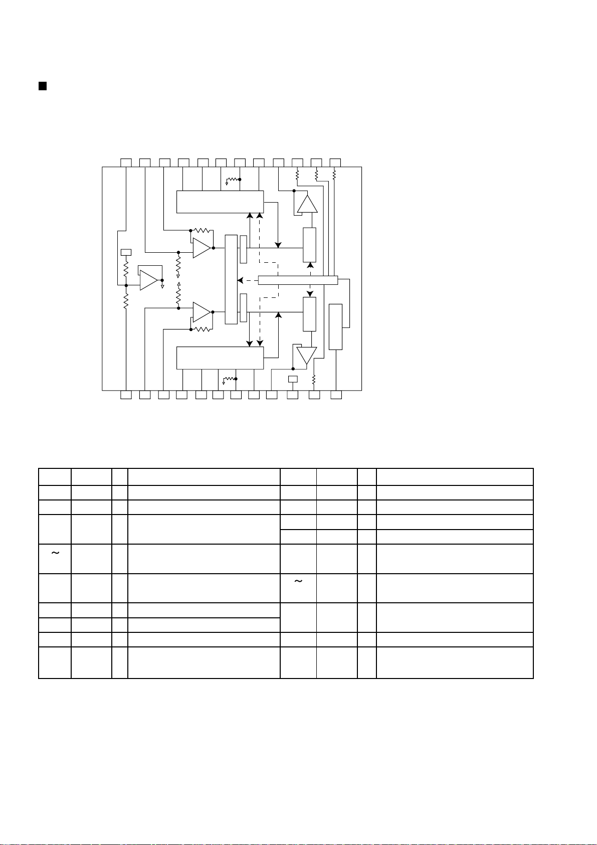
Description of major ICs
AN8806SB (IC601) : RF&Servo AMP
1.Terminal Layout
36
PD
LD
LDON
LDP
VCC
RF-
RF OUT
RF IN
C.AGC
ARF
C.ENV
C.EA
CS BDO
BDO
CS BRT
OFTR
/NRFDET
GND
1
2
3
4
5
6
7
8
9
10
11
12
13
14
15
16
17
18
35
34
33
32
31
30
29
28
27
26
25
24
23
22
21
20
19
PDAC
PDBD
PDF
PDE
PDER
PDFR
TBAL
FBAL
EF EF OUT
TE TE OUT
CROSS
TE BPF
VDET
LD OFF
VREF
ENV
RV-B550BU
2.Block Diagram
36
-+
35
-+
31
34
-+
32
33
-+
6
--
VCBA
+
29
728
-+
--
+
+
VCBA
--
+
VCBA
--
--
VCBA
+
+
--
-+
-+
+
--
27
-+
--
EQ
+
+
--
+
--
910 17
8
AGC
OFTR
BDO
RF
DET
11
12 19
ENV CURCUIT
13
14
15
16
-+
20
21
2
24 25
30
14
23
26
22
3
1-21
Page 22

RV-B550BU
3. Functions
Pin No.
1
2
3
4
5
6
7
8
9
10
11
12
13
14
15
16
17
18
19
20
21
22
23
24
25
26
27
28
29
30
31
32
33
34
35
36
Symbol
PD
LD
LD ON
LDP
VCC
RF-
RF OUT
RF IN
C.AGC
ARF
C.ENV
C.EA
CS BDO
BDO
CS BRT
OFTR
/NRFDET
GND
ENV
VREF
LD OFF
VDET
TE BPF
CROSS
TE OUT
TE-
FE OUT
FEFBAL
TBAL
PDFR
PDER
PDF
PDE
PD BD
PD AC
I/O
I
APC amp input terminal
APC amp output terminal
O
APC ON/OFF control terminal
I
--
Connect to ground
Power supply
-Inverse input pin for RF amp
I
RFamp output
O
RF input
I
Connecting pin of AGC loop filter
I/O
RF output
O
I/O
A capacitor is connected to this terminal to detect the envelope of RF signal
I/O
A capacitor is connected to this terminal to detect the envelope of RF signal
A capacitor is connected to detect the lower envelope of RF signal
I/O
BDO output pin
O
A capacitor is connected to detect the lower envelope of RF signal
I/O
O
Of-track status signal output
RF detection signal output
O
--
Ground
O
Envelope output
Reference voltage output
O
--
Connect to ground
O
Vibration detection signal output
I
Input pin of tracking error through BPF
O
Tracking error cross output
O
Tracking error signal output
Inverse input pin for tracking error amp
I
O
Output pin of focus error
Inverse input pin for focus error amp
I
I
Focus balance control
I
Tracking balance control
F I-V amp gain control
I/O
E I-V amp gain control
I/O
I
I-V amp input
I-V amp input
I
I
I-V amp input
Functions and operations
I I-V amp input
1-22
Page 23
RV-B550BU
1
2
3
4
5
6
7
- +
Level
shift
-+
+ Level
shift
+-
8
9
10
11
12
13
14
28
27
26
25
24
23
22
21
20
19
18
17
16
15
Level
shift
- +
Level
shift
+ -
-+
-+
D.BUF
D.BUF
DRIVER
MUTE
D.BUF
D.BUF
D.BUF
T.S.D
D.BUF
D.BUF
D.BUF
GND
CH4-OUTA
CH4-OUTB
CH4-INA
CH4-INB
BIAS IN
Vcc
CH1-OUTA
CH1-OUTB
CH1-INA
CH1-INB
TEST1
TEST2
MUTE
Vcc
CH3-INB
CH3-INA
CH3-OUTB
CH3-OUTA
OP IN(+)
OP IN(-)
CH2-INB
CH2-INA
CH2-OUTB
CH2-OUTA
GND
OP-OUT
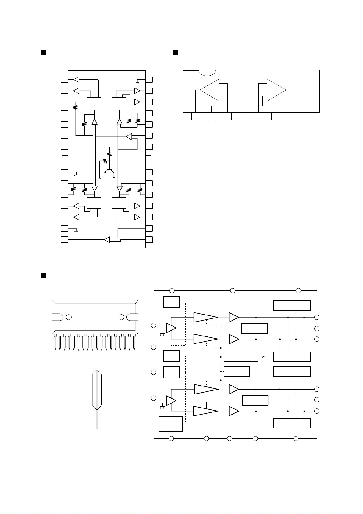
BA6897FP-W (IC602)
: 4channel driver
-+
+-
6
8 9 10 11
12
13
14
15
16
17
2
5
4
7
1813
RIPPLE
FILTER
BIAS
CIRCUIT
STANDBY
SW
IN
IN
POP NOISE
PREVENTION
CIRCUIT
PREDRIVER
PREDRIVER
PREDRIVER
PREDRIVER
POWER
POWER
POWER
POWER
LOAD SHORT
PROTECTOR
LOAD SHORT
PROTECTOR
THERMEL
SHUTDOWN
OVER VOLT AGE/
SURGE PROTECTOR
OUTPUT PIN TO Vcc
SHORT PROTECTOR
OUTPUT PIN TO Vcc
SHORT PROTECTOR
OUTPUT PIN TO GND
SHORT PROTECTOR
OUTPUT PIN TO GND
SHORT PROTECTOR
Vcc
POWER
GND1
POWER
GND2
Vcc2NCNC
GND
NC Vcc1
LA4705N
123456789101112131415161718
LA4705NA (IC631) : power amplifier
1
2
+
-
+
-
1
2
34
5
67
8
OUT1 -IN1
+IN1
VEE
+IN2 -IN2
OUT2
Vcc
BA15218N
BA15218N (IC801/IC831)
: Dual op amplifier
1-23
Page 24
RV-B550BU
BH3852S (IC501) : E.Volume
1.Block diagram
FILTER
IN2
24 23 22 21 20 19 18 17 16 15 14 13
Vcc
20k
20k
1 2 3 4 5 6 7 8 9 10 11 12
GND
NF2
+
(BASS) (TREBLE)
TONE CONTROL
IN1
NF1
BVN2
BIN2
BVO2
TIN2
2k
(BASS) (TREBLE)
TONE CONTROL
20k
+
47k
47k
BVN1
+
-
20k
BIN1
VOLUMEVOLUME
MATRIX SURROUND SOUND
2k
TIN1
BVO1
TVO2
CONTROL
TVO1
OUT2VCTC
10M
10M 10M
-
+
VOLUMEVOLUME
-
+
Vcc
Vcc
OUT1
BC
Ref.Voltage
10M
SC
VREF
2.Pin function
1
Pin name
GND
Pin No.
2
3
NF1
4 6
7.8
9
10
11
12
BASS1
TRE1
OUT1
VCC
LIVE
VREF
IN1
I/O
Grand terminal
Terminal for 1ch volume input
I
Terminal for gain adjustment of
I
Function Function
input step amp.
Terminal for connection of 1ch
low-frequency filter
Terminal for connection of 1ch
High frequency filter
Terminal for 1ch volume output
O
Terminal for power supply
Terminal for surround control
Terminal for reference voltage
O
output
Pin No.
13
14
15
16
17.18
19 21
22
23
24
Pin name
BASS
TRE
VOL
OUT2
TRE2
BASS2
NF2
IN2
VSET
I/O
Terminal for bass control
I
Terminal for treble control
I
Terminal for volume control
I
Terminal for 2ch volume output
O
Terminal for connection of 2ch
high-frequency filter
Terminal for connection of 2ch
low-frequency filter
Terminal for gain adjustment of
I
input step amp.
Terminal for 2ch volume output
I
Terminal for filter
-
1-24
Page 25
1. Layout
1
2
3
4
5
6
7
8
9
10
11
22
21
20
19
18
17
16
15
14
13
12
XT
FM/AM
CE
DI
CLOCK
DO
FM/ST/VCO
AM/FM
SDIN
XT
GND
LPFOUT
LPFIN
PD
VCC
FMIN
AMIN
IFCONT
IFIN
Pin
No.
1
2
3
4
5
6
7
8
9
10
11
Pin
No.
12
13
14
15
16
17
18
19
20
21
22
Symbol
XT
FM/AM
CE
DI
CLOCK
DO
FM/ST/VCO
AM/FM
SDIN
Symbol
IFIN
IFCONT
AMIN
FMIN
VCC
PD
LPFIN
LPFOUT
GND
XT
Function
X'tal oscillator connect (75kHz)
LOW:FM mode
When data output/input for 4pin(input) and
6pin(output): H
Input for receive the sirisl data from
controller
Sync signal input use
Data output for Controller
Output port
"Low": MW mode
Not use
Not use
Input/output port
Data input/output
Function
IF counter signal input
IF signal output
Not use
AM Local OSC signal output
FM Local OSC signal input
Power suplly(VDD=4.5-5.5V)
When power ON:Reset circuit move
PLL charge pump output(H: Local OSC
frequency Height than Reference frequency.
L: Low Agreement: Height impedance)
Input for active lowpassfilter of PLL
Output for active lowpassfilter of PLL
Connected to GND
X'tal oscillator(75KHz)
I/O
I
O
I
I
I
O
O
O
-
-
I/O
I/O
I
O
-
I
I
-
O
I
O
I
Reference
Driver
Phase
Detector
Charge Pump
Unlock
Detector
Universal
Counter
Swallow Counter
1/16,1/17 4bit
12bit
Programmable
DriverS
Swallow Counter
1/16,1/17 4bit
Data Shift Register & Latch
Power
on
Reset
C
2B
I/F
1/2
7821113
21
17
6
5
4
3
15
16
22
1
18
19
20
12
2. Block
3. Function
LC72136N(IC2):PLL Frequency synthesizer
RV-B550BU
1-25
Page 26
RV-B550BU
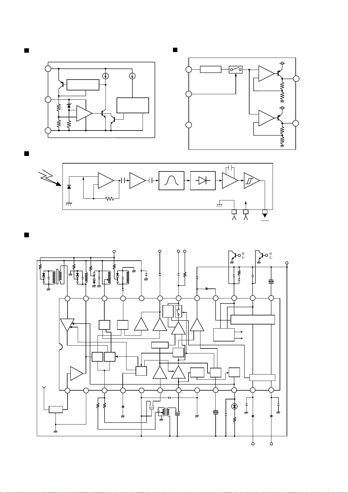
TA78DL06S(IC390) : Regulator
1
INPUT
SHORT
PROTECTION
GND
2
–
OVER VOLTAGE/
THERMAL SHUT
DOWN PROTECTION
+
3
+
–
Limiter Integrator Comparator
Amp.
OUTPUT
GP1U281X(IC903) : Remocon sensor
BA44W12ST-V5/Z1(IC310):Regulator
2
B.P.F
VCC
CTL
GND
5
3
Demodulator
+
–
+
–
4
1
OUT1
OUT2
TA2008AN (IC 1): FM/AM,IF/DET
FM
AM
OSC
AM
MIX
OUT
VT
FM
OSC
FM
OSC
AGC
+-
Block diagram
AM
ANTENNA
FM
ANTENNA
24 23 22 21 20 19 18 17 16 15 14 13
AM
RF
123456789101112
BPF
AM
RF IN
FM
RF
FM
RF IN
FM
RF OUTAMOSC
MIX
GND 1 MIX
OSC Buff OUT
V
CC1
Buff
AGC
V
CC2
Buff
1/8 DIV
FM
IF
OSC
0UT
AM
REQ
SW
FM IF
IF OUT
Buff
AM
DET
AM
IF OUT
/REQ
IF
IF
AM IF
IF REQ
+-
DET OUT
AF
Buff
LEVEL
DET
GND 2 FM
MPX IN
AM/FM
ST/MONO
SW
FM
DET
DET
GND
ST
LED
LPF 1
ST
IIND
VCC Vout
AM
FM
LPF 2
FM MPX
MUTE
L OUT
+-
MONO
SY
VCO
R OUT
+-
V
CC
1-26
L OUT
R OUT
Page 27

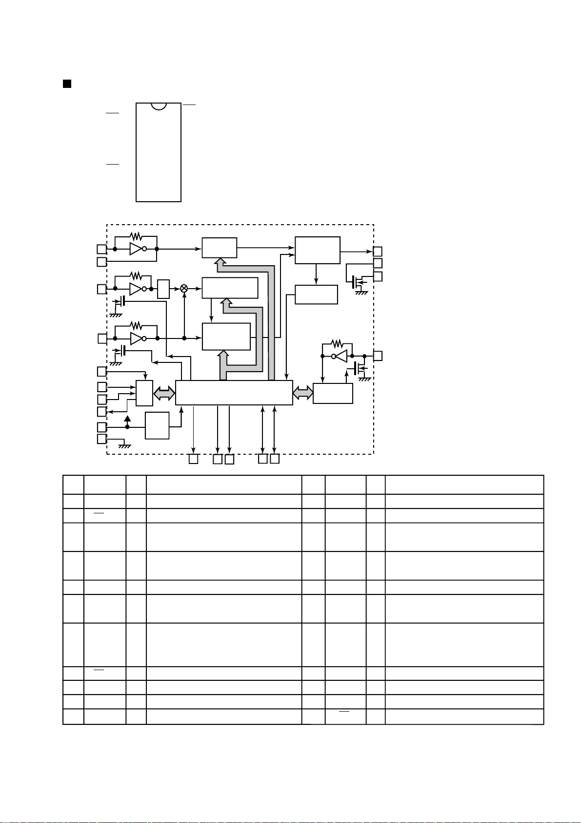
MN35510(IC603):DIGITAL SERVO&DIGITAL SIGNAL PROCESSER
RV-B550BU
1. Terminal Layout
2.Block Diagram
LRCKIN(MSEL)
BCLK(SSEL)
SRDATAIN
(PSEL)
IOSEL
CLVS
CRC
BLKCK
CLDCK
SBCK
SUBC
DEMPH
RESY
FLAG6(RESY)
SSEL
SQCK
SUBQ
AVDD2
AVDD2
PCK
EFM
PLLF
DSLF
IREF
DRF
ARF
RSEL
PSEL
MLD
MCLK
MDATA
CK384(EFM)
VCOF
BYTCK
SMCK
FCLK
CSEL
MSEL
X2
X1
ÊSTAT
DIGITAL
DEEMPHSIS
SUB
CODE
BUFFER
DSL.
PLL
VCO
VCO
ITUNING
GENERATION
PITCH
CONTROL
20 ~ 1
21
~
40
41 ~ 60
8TIMES
OVER SAMPUNC
DIGITAL FILTER
EFM
DEMODULATION
SYNC
INTERPOLATION
SUBCODE
DEMODULATION
MICRO
COMPUTER
INTERFACE
COVERTER
A/D
80
~
61
CIRC
ERROR
CORRECTION
DEINTERLEVE
CLV
SERVO
1BIT
DAC
LOGIC
S
16k
SRAM
INPUT
PEM
(R)
PEM
(L)
D/A
CONVERTER
OUTPUT
DIGITAL
AUDIO
INTERFASE
DIGITAL
AUDIO
INTERFASE
INTER POLATION
SOFT MUTING DIGITAL
ATTENUATION
PEAK DETECTIVE
AUTO CUE
PORT
SERVO
TIMING GENERATOR
AVSS1
AVDD1
OUTR
OUTL
FLAG
IPFLAG
TX
ECM
PC
LRCK
SRDATA
BCLK
DMUTE
TRKV
KICK
VREF
TRVSTR
ECS
TVD
TRD
FOD
TBAL
FBAL
TOFS
TES
/TLOCK
/FLOCK
PLAY
LDON
WVEL
SENSE
D
/
D
V
V
V
R
V
S
D
D
S
S
S
D
D
T
S
1
1
F
/
E
T
E
S
T
R
T
F
E
E
N
V
T
R
C
R
S
B
V
D
D
O
E
T
/
R
F
D
E
O
F
T
1-27
Page 28

RV-B550BU
3. Description
Pin
symbol
No.
BCLK
1
2
LRCK
SRDATA
3
4
DVDD1
DVSS1
5
TX
6
7
MCLK
MDATA
8
MLD
9
10
SENSE
11
FLOCK
12
TLOCK
13
BLKCK
14
SQCK
15
SUBQ
16
DMUTE
STATUS
17
18
RST
19
SMCK
20
PMCK
21
TRV
22
TVD
23
PC
24
ECM
25
ECS
26
KICK
27
TRD
28
FOD
29
VREF
30
FBAL
31
TBAL
FE
32
TE
33
34
RF ENV
35
VDET
OFT
36
37
TRCRS
38
RFDET
BDO
39
LDON
40
I/O
O
Not used
Not used
O
O
Not used
I
Power supply (Digital)
I
Connected to GND
Digital audio interface output
O
Micom command clock signal input
I
(Data is latched at signal's rising point)
Micom command data input
I
I
Micom command load signal input
Sence signal output
O
O
Focus lock signal output Active :Low
O
Tracking lock signal output Active :Low
sub-code - block - clock signal output
O
I
Outside clock for sub-code Q resister input
Sub-code Q -code output
O
I
Connected to GND
Status signal
O
(CRC,CUE,CLVS,TTSTOP,ECLV,SQOK)
Reset signal input (L:Reset)
I
I
Not used
I
Not used
O
Traverse enforced output
O
Traverse drive output
I
Not used
Spindle motor drive signal (Enforced
O
mode output) 3-State
Spindle motor drive signal (Servo error
O
signal output)
Kick pulse output
O
Tracking drive output
O
O
Focus drive output
Reference voltage input pin for D/A
I
output block (TVD,FOD,FBA,TBAL)
Focus Balance adjust signal output
O
O
Tracking Balance adjust signal output
Focus error signal input(Analog input)
I
Tracking error signal input(Analog input)
I
I
RF envelope signal input(Analog input)
Vibration detect signal input(H:detect)
I
Off track signal input(H:off track)
I
Track cross signal input
I
RF detect signal input(L:detect)
I
BDO input pin(L:detect)
I
Laser ON signal output(H:on)
O
Description
Pin
No.
41
42
43
44
45
46
47
48
49
50
51
52
53
54
55
56
57
58
59
60
61
62
63
64
65
66
67
68
69
70
71
72
73
74
75
76
77
78
79
80
symbol
TES
PLAY
WVEL
ARF
IREF
DRF
DSLF
PLLF
VCOF
AVDD2
AVSS2
EFM
PCK
PDO
SUBC
SBCK
VSS
XI
X2
VDD
BYTCK
CLDCK
FLAG
IPPLAG
FLAG
CLVS
CRC
DEMPH
RESY
IOSEL
TEST
AVDD1
OUT L
AVSS1
OUT R
RSEL
CSEL
PSEL
MSEL
SSEL
I/O
Tracking error shunt signal output(H:shunt)
O
I
Not used
I
Not used
I
RF signal input
I
Reference current input pin
Bias pin for DSL
I
I/O
Loop filter pin for DSL
Loop filter pin for PLL
I/O
I
Not used
I
Power supply(Analog)
Connected to GND(Analog)
Not used
III
Not used
I
Not used
I
Not used
I
Not used
Connected to GND(for X'tal oscillation
I
circuit)
Input of 16.9344MHz X'tal oscillation circuit
I
Output of X'tal oscillation circuit
O
I
Power supply(for X'tal cscillation circuit)
I
Not used
I
Not used
I
Not used
I
Not used
I
Not used
I
Not used
I
Not used
Not used
I
Not used
III
pull up
pull up
Power supply(Digital)
Lch audio output
O
I
Connected to GND
Rch audio output
O
II
pull up
Connected to GND
I
Connected to GND
I
Connected to GND
I
Pull up
Description
1-28
Page 29

BA15218F-XE(IC401/751):OP AMP.
RV-B550BU
EE
1OUT1
2-IN1
1
3+IN1
+
4
-
2
+
8
7
6
5V
VCC
OUT2
-IN2
+IN2
1-29
Page 30

RV-B550BU
VICTOR COMPANY OF JAPAN, LIMITED
AUDIO DIVISION,10-1,1Chome,Ohwatari-machi,Maebashi-city,371-8543,Japan
(No.20826C)
Printed in Japan
200101 (V )
Page 31

PARTS LIST
[ RV-B550BU ]
* All printed circuit boards and its assemblies are not available as service parts.
RV-B550BU
- Contents -
Exploded view of general assembly and parts list
CD mechanism assembly and parts list
Cassette mechanism assembly and parts list
Electrical parts list
Packing materials and accessories parts list
Area suffix
UY ---------------------- Argentina
3- 2
3- 7
3- 8
3-13
3-24
3-1
Page 32

RV-B550BU
Exploded view of general assembly and parts list
Block No.
M
M
1
M
5
Front Cabinet
86
86
3
2
3
a
3
13
4
4
b
5
4
86
12
14
86
84
108
3
6
3
2
3
3
10
1
20
20
15
21
85
86
2
23
17
22
19
24
27
25
16
18
26
86
86
1
3-2
ABCD
Page 33

Exploded view of general assembly and parts list
Block No.
Rear Cabinet
53
5
48
47
91
40
58
68
69
Back light board
RV-B550BU
M
M
1
M
62
34
51
50
61
Key switch board
9
9
38
88
64
66
59
43
8
70
66
7
9
35
37
T
ra
n
s
97
bo
87
a
rd
78
36
99
80
80
Main
board
9
11
37
39
76
88
Battery
board
75
74
65
109
CD door
switch board
88
63
Cassette sw
28
42
93
102
41
44
92
42
90
89
45
Tuner board
32
itch board
106
101
72
105
77
88
Micon
board
42
107
46
42
103
104
82
71
88
83
88
87
73
31
56
55
57
54
4
38
78
49
52
35
100
36
33
39
98
3
79
94
79
Power supply
2
board
95
96
110
67
29
60
32
Head amp. & mecha. control board
1
30
29
ABC
29
3-3
Page 34

RV-B550BU
)
)
Parts list(General assembly)
Item Parts number Parts name Area
A
1 LV10160-012A FRONT CABI ASSY 1 H.F.WELDING
2 LE10010-012A SPEAKER 2 L/R
3 QYSBSF3010Z SCREW 8 FOR SPK.
4 QYSBST3006Z T.SCREW 4 SPK+LED PWB
5 LV41752-001A SPK.LED HOLDER 2
6 VJK4520-081 LCD LENS 1 AS SILK X 1
7 LV20331-001A POWER BUTTON 1
8 LV20332-001A VOLUME BUTTON 1
9 QYSBSF2610Z SCREW 6 BUTTON + SW PWB
10 LV40715-002A LENS 1 AS PAD X 1
11 LV40716-002A LED HOLDER 1 ABS
12 LV40750-001A PACKING SHEET L 1 PEFU(FRONT CABI
13 LV40751-001A PACKING SHEET R 1 PEFU(FRONT CABI
14 QYSBSFG3010Z TAP SCREW 1 SPK.CON+FRONT
15 LV20298-003A CASSETTE HOLDER 1 MIPS
16 VKZ4794-002 SPECIAL SCREW 3 EJECT SAFTY
17 LV20299-005A DOOR COVER 1
18 LV30844-001A EJECT SAFTY 1 CASS HOLDER
19 LV40717-003A DOOR LENS 1 PC SILK X 2
20 VKY4180-001 CASSETTE SPRING 2 SUS
21 VYH5601-001 GEAR 1 POM
22 LV40718-001A EJECT KNOB 1 ABS
23 LV40719-001A CAM(CASS
24 LV40749-001A TENSION SPRING 1 CAM + DOOR COVE
25 QYSDSF2614Z SCREW 1 E.KNOB + CAM
26 LV40721-001A DOOR SPRING 1 SUS T1.0
27 LV40720-002A COLLAR (CASS
28 ------------ SLC MECHA ASS'Y 1
29 QYSBSF3014Z SCREW 4 FOR SLC
30 LV30845-001A HEAD SHIELD 1 SPTE T 0.4
31 LV10192-001A CASS CHASSIS 1 MIPS
32 VYSA1R6-080 SPACER 2 FOR CASS CHASSI
33 ------------ EXL-M6MAYPM 1
34 VJD5410-205 PICK COVER 1
35 QYSDSF2006M SCREW 4
36 VKZ4791-001 INSULATOR 2
37 VKZ4791-001 INSULATOR 2
38 LV40723-001A CD MECHA HOLDER 2 EGC T1.0
39 QYSBSF3010Z SCREW 4 FOR HOLDER
40 LV10162-009A CD CASE 1 MIPS
41 LV31305-001A SHIELD 1 FOR CD CASE
42 QYSBSF3010Z SCREW 4 FOR MICON PWB
43 LV40726-001A LOCK LEVER 1 POM
44 VYH4769-002SS GEAR 1 FOR CD CASE
45 VXL4442-001 VOLUME KNOB 1 MIC VOLUME
46 VYSA1R6-080 SPACER 2 FOR MICON PWB
47 LV10163-008A CD DOOR 1
48 PQ45130-7 JVC MARK 1 FOR CD DOOR
Q'ty Description
1 POM
1 SLIDER + D.COVE
Block No. M1MM
3-4
Page 35

RV-B550BU
)
)
)
)
)
)
)
Parts list(General assembly)
Item Parts number Parts name Area
A
49 VYH3644-201 CLAMPER 1 FOR OPTIMA-6
50 VYH7313-003 MAGNET 1
51 VYH7314-001 YOKE 1
52 VYH7315-005 PAD 1
53 LV40718-001A EJECT KNOB 1 ABS
54 QYSBSF2610Z SCREW 1 E.KNOB + SLIDER
55 LV30846-001A SLIDER(CD
56 LV40725-001A TORSION SPRING 1 FOR SLIDER
57 LV40728-002A COLLAR(CD
58 LV40729-002A CD DOOR SPRING 1 SUS
59 LV30847-001A HEAT SINK(A
60 QYSBSF3012Z SCREW 2 HEAT SINK(A)+PW
61 LV30848-001A HEAT SINK(B
62 E65923-003 TAPPING SCREW 2 FOR AC
63 QYSBSF3012Z SCREW 3 FOR POWER IC
64 QYSBSF3012Z SCREW 2 H.SINK(A)+BKT.
65 LV40730-001A HEAT SINK BKT 1 FOR HEAT SINK
66 QYSBSF3010Z SCREW 2 REAR + H.BKT.
67 VYSA1R6-080 SPACER 1 FOR AMP PWB
68 LV30849-001A LCD HOLDER 1 SPTE T0.4
69 VYH8193-002 SHEET 1 LCD + LCD HOLDE
70 LV10164-030A REAR CABINET 1 MIPS
71 VND4118-004 CAUTION LABEL 1 FOR REAR
72 FMJA3001-00A(D
73 VYH5012-006 TERMINAL LUG 1 SPTE T0.4
74 QYSBSF3012Z SCREW 1 TUNER HOLDER+RE
75 LV41032-001A TUNER HOLDER 1
76 E65923-003 TAPPING SCREW 1 FOR H.PHONES
77 QYSDSP3012N SCREW 1 FOR ROD ANT
78 VYH8101-001 TRANS SUPPORT 2 POM
79 QYSBSF3030Z SCREW 4 FOR TRANS
80 LV30225-021A SPACER 2 TRANS WIRE
82 VJC2016-341 BATTERY COVER 1 MIPS
83 VYH5657-001 BATTERY SPRING 1
84 LV10165-005A SIDE PROT.ASY L 1
85 LV10166-005A SIDE PROT.ASY R 1
86 QYSBSF3012N SCREW 12 FOR SIDE PROTEC
87 VKH3012-073 SHAFT(E
88 QYSBSF3040Z SCREW 8 FRONT+REAR
89 QYSBSF3010Z SCREW 2 CD CASE + REAR
90 LV31998-004A NAME PLATE
A
91 LV40231-001A CAUTION LABEL 1
92 QLD0024-002 L.C.DISPL.PANEL 1
93 E70306-001 HEAT SINK 1
94 QQT0247-004 POWER TRANS
A
95 QMF51E2-4R0-J1 FUSE
A
96 QMF51E2-6R3-J1 FUSE
A
97 LV41029-001A HEAT SINK 1
ROD ANT ASS'Y 1
Q'ty Description
1 POM
1
1 AL T2.0
1
2 REAR(S.BELT
1
1
1 F1902
1 F1904
Block No. M1MM
3-5
Page 36

RV-B550BU
Parts list(General assembly)
Item Parts number Parts name Area
A
98 QMF51E2-R80-J1 FUSE 1
99 QJJ010-060606 SIN CR C-C WIRE 1
100 QUQ610-1508AJ FFC WIRE 1
101 QUQC12-0806CJ FFC WIRE 1
102 QUQC12-1006CJ FFC WIRE 1
103 QUQ412-1313CJ FFC WIRE 1
104 QUQ412-1415CJ FFC WIRE 1
105 QUQ412-1012DJ FFC WIRE 1
106 QUQ412-0914DJ FFC WIRE 1
107 QUQ412-0912CJ FFC WIRE 1
108 WJJ0034-010A E-SI C WIRE C-C 1
109 QYSBSSF3010Z SCREW 1
110 QYSBSF3014Z SCREW 1
Q'ty Description
F1901
Block No. M1MM
3-6
Page 37

CD mechanism assembly and parts list
Grease Point
FG-87HS
(Grease to apply have to be a little for the exchange.)
3
FG-87HS
FG-87HS
Block No.
RV-B550BU
2
M
M
M
2
0.1mm
+
-
19.4
FG-87HS
12
1
EXL-M7TMB
Turn table hight
EXL-M7MB
ABC
Parts list ( CD mechanism )
A
Item
1 E102731-221SM MECHA BASE 1
2 OPTIMA-7B OPTICAL PICK UP 1
3 E406777-002SM CD SHAFT 1
4 LV31002-001A CD RACK 1
5 E307745-441SM MECHA GEAR 1
6 QYSDSP2003N SCREW 4
7 E406750-442SM PINION GEAR 1
8 EPB-001PK TURN TABLE 1 SINGLE CD
9 E406784-001 FEED MOTOR 1
10 QAR0130-001 SPPINDLE MOTOR 1
11 EMW10190-441 P.C.BOARD 1
12 QGA2001F1-06 6P PLUG ASSY 1
13 QSW0506-001 LEAF SWITCH 1
14 E75832-221SS SPECIAL SCREW 1
Parts number Parts name
EPB309173PKA TURN TABLE 1 CHANGER CD
Q'ty
Block No. M2MM
Description
Area
3-7
Page 38

RV-B550BU
Cassette mechanism assembly and parts list
SLC-S1YPM
5
4
Block No.
M
3
M
M
C
C
3
63
Cassette switch board
2
Head amplifier &
mechanism control board
mm
1
3-8
0.1
0.15
+
-
8.7
Motor pulley hight
ABCD
Page 39

RV-B550BU
)
)
)
)
)
)
Parts list(Cassette mechanism)
Item Parts number Parts name Area
A
1 VKS1165-00G CHASSIS B.ASS'Y 1
4 VKS2274-002 REEL GEAR 2
5 VKW5286-002 B.T. SPRING 2
6 VKS5559-001 PLAY IDLE GEAR 1
7 VKS5597-00A BUND ASS'Y 1
8 VKW5296-001 EARTH SPRING 1
9 VKR4749-003 IDLE PULLEY 1
10 VKH5786-003 SHAFT 1
11 VKS2275-00E HEAD MOUNT ASSY 1
12 VKS1167-003 HEAD MOUNT BASE 1
14 LV41089-001A R/P&E HEAD 1 VKS2275-00B
18 VKW5302-001 HEAD SPRING 1
19 VKZ4730-001 SPECIAL SCREW 2
20 VKS2277-005 DIRECTION LEVER 1
21 VKP4233-00A PINCH ROL. ASSY 2
24 VKW5299-002 PIN ROL.SP.(R
25 VKW5300-002 PIN ROL.SP.(L
26 VKW5285-001 RETURN SPRING 1
27 VKY3149-002 CASSETTE SP. 1
28 VKM3906-002 PLAY SW LEVER 1
29 VKS1166-003 CONTROL CAM 1
30 VKW5279-001 HEAD BASE SP(R
31 VKW5280-001 HEAD BASE SP(L
32 VKS5603-00D MAIN PULLEY ASY 1
33 VKS3785-001MM FR ARM 1
34 VKW5284-002 SWING SPRING 1
35 VKS2278-003 TRIGGER ARM 1
36 VKW5301-001 FR SPRING 1
37 VKW5266-001 ELEVATOR SPRING 1
38 WDL214025 WASHER 1
39 VKS3786-00G CLUTCH ASS'Y 1
45 VKF3205-00B F.WHEEL ASSY(R
48 WDL183425 SLIT WASHER 1
49 VKF3207-00B F.WHEEL ASSY(L
52 WDL173525-6 SLIT WASHER 1
53 VKZ3174-00A DC SOLENOID 1
56 VKB3000-181 CAPSTAN BELT 1
57 MSI-5U2LWA D.C.MOTOR ASS'Y 1
58 VKR4761-001 MOTOR PULLEY 1
59 QYSPSP2604Z SCREW 2
61 QYSBSF2608Z T.SCREW 3 FOR P.W.B.
63 QYSBSF2006Z SCREW 1
Q'ty Description
1
1
1
1
1
1
Block No. M3MM
3-9
Page 40

RV-B550BU
Grease point 1/3
Grease
*
5
EM-30L
UD-24
LEN-320M
*
EM-30L
*
Fig.2
EM-30L
Fig.1
*
EM-30L
Fig.2
4
Fig.1
Fig.3
*
EM-30L
3
Fig.3
2
1
3-10
Fig.4
EM-30L
*
EM-30L
*
EM-30L
*
(Remove the Head mount Ass'y on the Chasis Base)
Fig.4
ABCD
*
EM-30L
Page 41

RV-B550BU
Grease point
EM-30L
*
2/3
*
EM-30L
5
Fig.1
Fig.5
4
Fig.5
Fig.1
EM-30L
3
Fig.2
Fig.4
2
EM-30L
Fig.3
LEN-320M
Note: It is a putting up of the control
cam to UD-24H(Hanarl) and
LEN-320M(Grease)dipping on the
Control cam
*
Fig.2
1
Fig.4
Fig.3
ABC
3-11
Page 42

RV-B550BU
Grease point 3/3
*
EM-30L
*
EM-30L
*
EM-30L
*
EM-30L
5
Fig.1
Fig.2
Fig.2
4
Fig.1
Fig.3
3
Fig.5
Fig.4
2
Fig.3
UD-24
*
EM-30L
EM-30L
*
Fig.6
UD-24
Fig.4
1
3-12
Fig.5
Fig.6
ABCD
Page 43

)
)
Electrical parts list
Electrical parts list(Micon board)
Item
A
C 604 QEKC1AM-107Z E CAPACITOR 100MF 20% 10V
C 605 QETN1HM-106Z E CAPACITOR 10MF 20% 50V
C 606 NCB21HK-102X C CAPACITOR
C 607 NCB21HK-102X C CAPACITOR
C 608 QETN1HM-105Z E CAPACITOR 1.0MF 20% 50V
C 609 NCS21HJ-101X C CAPACITOR
C 610 QFLM1HJ-273Z M CAPACITOR .027MF 5% 50V
C 611 NCB21HK-472X C CAPACITOR
C 612 NCB21HK-103X C CAPACITOR
C 613 NCS21HJ-331X C CAPACITOR
C 614 QFVF1HJ-104Z TF CAPACITOR .10MF 5% 50V
C 615 NCB21HK-223X C CAPACITOR
C 616 NCB21HK-223X C CAPACITOR
C 617 NCB21HK-223X C CAPACITOR
C 618 NCB21HK-222X C CAPACITOR
C 619 NCS21HJ-271X C CAPACITOR
C 620 NCS21HJ-181X C CAPACITOR
C 622 QETN1EM-476Z E CAPACITOR 47MF 20% 25V
C 623 QFVF1HJ-104Z TF CAPACITOR .10MF 5% 50V
C 628 QDX31EM-473Z C CAPACITOR
C 629 QETN1AM-107Z E CAPACITOR 100MF 20% 10V
C 631 QETN1AM-477Z E CAPACITOR 470MF 20% 10V
C 632 QEKC1AM-107Z E CAPACITOR 100MF 20% 10V
C 640 NCB21HK-822X C CAPACITOR
C 641 NCB21HK-223X C CAPACITOR
C 651 NCS21HJ-270X C CAPACITOR
C 652 NCS21HJ-270X C CAPACITOR
C 653 NCB21HK-223X C CAPACITOR
C 655 QDX31EM-473Z C CAPACITOR
C 661 NCS21HJ-471X C CAPACITOR
C 662 NCB21HK-223X C CAPACITOR
C 663 QFLM1HJ-223Z M CAPACITOR .022MF 5% 50V
C 664 NCB21HK-223X C CAPACITOR
C 665 QFVF1HJ-104Z TF CAPACITOR .10MF 5% 50V
C 671 NCB21HK-222X C CAPACITOR
C 672 NCB21HK-222X C CAPACITOR
C 673 QTE1A28-227Z E CAPACITOR
C 674 NCB21HK-223X C CAPACITOR
C 675 NCB21HK-102X C CAPACITOR AG-DG
C 691 NCS21HJ-151X C CAPACITOR DENGEN NOISE
C 692 NCS21HJ-151X C CAPACITOR DENGEN NOISE
C 693 NCS21HJ-151X C CAPACITOR DENGEN NOISE
C 694 NCS21HJ-151X C CAPACITOR DENGEN NOISE
C 696 NCS21HJ-101X C CAPACITOR
C 697 NCS21HJ-101X C CAPACITOR
C 698 NCS21HJ-101X C CAPACITOR
C 699 NCS21HJ-101X C CAPACITOR
CN251 QGF1205C1-10 CONNECTOR
CN252 QGF1205C1-08 CONNECTOR
CN403 QGF1205C1-09 CONNECTOR
CN405 QGF1205F1-10 CONNECTOR
CN406 QGF1205F1-09 CONNECTOR
CN407 QGF1205F1-13 CONNECTOR
CN408 QGF1205F1-14 CONNECTOR
CN601 QGF1008F1-15 21-41 CONNECTOR TO RF
CN602 QGA2001C1-06 6P PLUG ASSY
CN901 QGF1205F1-10 CONNECTOR
CN902 QGF1205F1-08 CONNECTOR
CN904 QGA2501F1-02 CONNECTOR
CN907 QGA2501C1-02 2P CONNECTOR
C2501 QER61AM-226Z E CAPACITOR 22MF 20% 10V
C2502 QER41CM-476 E CAPACITOR 47MF 20% 16V
C3361 QER41AM-107 E CAPACITOR 100MF 20% 10V
Parts number Parts name Area
Block No. 01
Remarks
RV-B550BU
Item
Parts number Parts name Area
C3362 QER61EM-475Z E CAPACITOR 4.7MF 20% 25V
C3571 QER41CM-476 E CAPACITOR 47MF 20% 16V
C4142 NCS21HJ-100X C CAPACITOR
C4143 QER61EM-475Z E CAPACITOR 4.7MF 20% 25V
C4144 QER61EM-475Z E CAPACITOR 4.7MF 20% 25V
C4145 QTE1V06-106Z E CAPACITOR
C4151 NCB21HK-681X C CAPACITOR
C4242 NCS21HJ-100X C CAPACITOR
C4243 QER61EM-475Z E CAPACITOR 4.7MF 20% 25V
C4244 QER61EM-475Z E CAPACITOR 4.7MF 20% 25V
C4245 QTE1V06-106Z E CAPACITOR
C4251 NCB21HK-681X C CAPACITOR
C4341 QER41CM-476 E CAPACITOR 47MF 20% 16V
C4342 QER61CM-107Z E CAPACITOR 100MF 20% 16V
C4343 NCS21HJ-151X C CAPACITOR
C4344 QER61EM-475Z E CAPACITOR 4.7MF 20% 25V
C7351 QET N1 HM-226Z E CAPACITOR 22MF 20% 50V
C7352 QET N1 HM-226Z E CAPACITOR 22MF 20% 50V
C7353 NCS21HJ-390X C CAPACITOR
C7354 QET N1 HM-335Z E CAPACITOR 3.3MF 20% 50V
C7355 QER61HM-474Z E CAPACITOR .47MF 20% 50V
C7356 QET N1 HM-336Z E CAPACITOR 33MF 20% 50V
C7357 QET N1 HM-335Z E CAPACITOR 3.3MF 20% 50V
C7358 QET N1 HM-475Z E CAPACITOR 4.7MF 20% 50V
C9001 NCS21HJ-220X C CAPACITOR SUB CLOCK
C9002 NCS21HJ-220X C CAPACITOR SUB CLOCK
C9003 NCS21HJ-151X C CAPACITOR BEAT
C9004 NCS21HJ-471X C CAPACITOR
C9005 NCS21HJ-240X C CAPACITOR MAIN CLOCK
C9006 NCS21HJ-240X C CAPACITOR MAIN CLOCK
C9007 NCS21HJ-360X C CAPACITOR MAIN CLOCK
C9008 NCS21HJ-360X C CAPACITOR MAIN CLOCK
C9009 NCB21HK-103X C CAPACITOR VDD
C9011 NCB21HK-103X C CAPACITOR RESET
C9012 QER61HM-226Z E.CAPACITOR 22MF 20% 50V
C9013 NCS21HJ-151X C CAPACITOR
C9015 NCS21HJ-151X C CAPACITOR
C9016 NCS21HJ-151X C CAPACITOR
C9017 NCS21HJ-151X C CAPACITOR
C9018 QER41AM-107 E CAPACITOR 100MF 20% 10V
C9019 QER61HM-106Z E CAPACITOR BASS
C9020 QER61HM-106Z E CAPACITOR TRE
C9021 QER61HM-106Z E CAPACITOR 10MF 20% 50V
C9022 NCB21HK-103X C CAPACITOR AVREF
C9023 NCS21HJ-151X C CAPACITOR
C9024 NCS21HJ-101X C CAPACITOR
C9025 NCS21HJ-151X C CAPACITOR
C9026 NCS21HJ-151X C CAPACITOR
C9027 NCS21HJ-680X C CAPACITOR
C9031 NCB21HK-103X C CAPACITOR
C9034 NCS21HJ-151X C CAPACITOR
C9035 NCS21HJ-151X C CAPACITOR
C9036 NCS21HJ-151X C CAPACITOR
C9037 NCS21HJ-151X C CAPACITOR
C9038 NCS21HJ-151X C CAPACITOR
C9039 NCB21HK-103X C CAPACITOR
C9040 NCB21HK-102X C CAPACITOR
D 661 1SS133-T2 SI DIODE
D2502 SLR-342VR-T15 LED STAND-BY LED
D2504 SLR-342MG-T15 LED ACS IND (GR
D2505 1SS133-T2 SI DIODE
D2506 SLR-342VR-T15 LED AHB ON/OFF(R
D2507 1SS133-T2 SI DIODE
Remarks
3-13
Page 44

RV-B550BU
Q
Q
Q
Q
Q
Q
Q
Q
Q
Q
Q
Q
Q
Q
Q
Q
Q
Q
Q
Q
Q
Q
Q
Q
Q
Q
Electrical parts list(Micon board)
Item
A
A
A
Parts number Parts name Area
D2508 SELU2E10C LED 3MMLED
D2509 SELU2E10C LED 3MMLED
D3361 1SS133-T2 SI DIODE
D3362 MTZJ3.9B-T2 Z DIODE
D3363 1SS133-T2 SI DIODE
D4301 1SS133-T2 SI DIODE
D4302 1SS133-T2 SI DIODE
D7351 1SS133-T2 SI DIODE
D7352 1SS133-T2 SI DIODE
D7353 1SS133-T2 SI DIODE
D9001 1SS133-T2 SI DIODE
D9002 MTZJ5.1C-T2 ZENER DIODE
D9006 MA700A-T2 S.B.DIODE
ICH01 VYH7237-002 IC HOLDER FOR MICON
IC401 BA15218F-XE IC ADDER
IC601 AN8806SB-W IC RF AMP
IC602 BA6897FP-W IC
IC603 MN35510 IC 1CHIP PROCESSER
IC751 BA15218F-XE IC
IC901 MN171603BJ1 IC SYSTEM MICON
IC902 IC-PST9131-T IC
IC903 GP1U281X IC
J4301 QNS0047-001 JACK AUX
J7351 QNS0043-001 JACK
K 698 QQR0779-001Z INDUCTOR B4121
K 699 QQR0779-001Z INDUCTOR
K9001 QQR0779-001Z INDUCTOR
L4351 QQR0779-001Z INDUCTOR
L4352 QQR0779-001Z INDUCTOR
L4353 QQL01BK-100Z INDUCTOR
L4354 QQR0779-001Z INDUCTOR
L4355 QQL01BK-100Z INDUCTOR
L4356 QQR0779-001Z INDUCTOR
L9001 QQL01BK-100Z INDUCTOR
L9002 QQL01BK-100Z INDUCTOR
PL 1 QLL0051-002 LAMP
601 2SA952/LK/-T TRANSISTOR
631 2SA952/LK/-T TRANSISTOR
2501 DTA124XKA-X CHIP D . TR
2504 UN2210-X TRANSISTOR
2505 2SC2412K/RS/-X CHIP TRANSISTOR
2506 DTC124TKA-X TRANSISTOR
3361 2SA1037AK/RS/-X TRANSISTOR
3362 2SD601A/R/-X TRANSISTOR
3571 2SB624/4/-X TR ANSISTOR
3572 2SD601A/R/-X TRANSISTOR
4101 2SD2144S/VW/-T TRANSISTOR
4102 2SD596/4/-X TRAN SISTOR
4201 2SD2144S/VW/-T TRANSISTOR
4202 2SD596/4/-X TRAN SISTOR
4301 2SD601A/R/-X TRANSISTOR
7351 2SD601A/R/-X TRANSISTOR
7352 2SD601A/R/-X TRANSISTOR
7353 2SA1037AK/RS/-X TRANSISTOR
7354 UN2216-X TRANSISTOR
9001 2SC2714/O/-X TRANSISTOR MAIN CLOCK
9002 2SC2714/O/-X TRANSISTOR MAIN CLOCK
9003 2SD601A/R/-X TRANSISTOR
9006 2SA1037AK/RS/-X TRANSISTOR
9010 UN2210-X TRANSISTOR
9011 UN2210-X TRANSISTOR
9013 UN2210-X TRANSISTOR
R 601 NRSA02J-113X MG RESISTOR
Block No. 01
Remarks
DRIVER
TUNER SW
Item
A
R 603 NRSA02J-125X MG RESISTOR
R 605 NRSA02J-274X MG RESISTOR
R 606 NRSA02J-154X MG RESISTOR
R 607 NRSA02J-273X MG RESISTOR
R 609 NRSA02J-104X MG RESISTOR
R 610 NRSA02J-154X MG RESISTOR
R 612 NRSA02J-102X MG RESISTOR
R 613 NRSA02J-121X MG RESISTOR
R 614 NRSA02J-100X MG RESISTOR
R 615 NRSA02J-120X MG RESISTOR
R 616 NRSA02J-910X MG RESISTOR
R 621 NRSA02J-330X MG RESISTOR
R 622 NRSA02J-330X MG RESISTOR
R 623 NRSA02J-330X MG RESISTOR
R 631 NRSA02J-331X MG RESISTOR
R 632 NRSA02J-101X MG RESISTOR
R 633 NRSA02J-273X MG RESISTOR
R 641 NRSA02J-563X MG RESISTOR
R 642 NRSA02J-123X MG RESISTOR
R 643 NRSA02J-822X MG RESISTOR
R 644 NRSA02J-223X MG RESISTOR
R 645 NRSA02J-223X MG RESISTOR
R 646 NRSA02J-222X MG RESISTOR
R 647 NRSA02J-472X MG RESISTOR
R 651 NRSA02J-102X MG RESISTOR
R 652 NRSA02J-102X MG RESISTOR
R 653 NRSA02J-102X MG RESISTOR
R 654 NRSA02J-102X MG RESISTOR
R 655 NRSA02J-471X MG RESISTOR
R 659 NRSA02J-221X MG RESISTOR
R 661 NRSA02J-683X MG RESISTOR
R 662 NRSA02J-155X MG RESISTOR
R 663 NRSA02J-124X MG RESISTOR
R 664 NRSA02J-471X MG RESISTOR
R 666 NRSA02J-220X MG RESISTOR
R 671 NRSA02J-103X MG RESISTOR
R 672 NRSA02J-103X MG RESISTOR
R 696 NRSA02J-222X MG RESISTOR
R 697 NRSA02J-474X MG RESISTOR
R2501 NRS181J-271X MG RESISTOR
R2502 NRSA02J-391X MG RESISTOR
R2503 NRSA02J-391X MG RESISTOR
R2504 NRSA02J-101X MG RESISTOR
R2505 NRSA02J-101X MG RESISTOR
R2506 NRSA02J-121X MG RESISTOR
R2507 NRSA02J-151X MG RESISTOR
R2508 NRSA02J-221X MG RESISTOR
R2509 NRSA02J-271X MG RESISTOR
R2510 NRSA02J-391X MG RESISTOR
R2511 NRSA02J-561X MG RESISTOR
R2512 NRSA02J-102X MG RESISTOR
R2513 NRSA02J-182X MG RESISTOR
R2514 NRSA02J-391X MG RESISTOR
R2515 NRSA02J-473X MG RESISTOR
R2516 NRS181J-473X MG RESISTOR
R2518 NRSA02J-223X MG RESISTOR
R2520 NRSA02J-391X MG RESISTOR
R2521 NRSA02J-102X MG RESISTOR
R2522 NRSA02J-102X MG RESISTOR
R2523 NRSA02J-332X MG RESISTOR
R3361 NRSA02J-390X MG RESISTOR
R3362 NRSA02J-102X MG RESISTOR
R3363 NRSA02J-472X MG RESISTOR
Parts number Parts name Area
Remarks
3-14
Page 45

RV-B550BU
Electrical parts list(Micon board)
Item
A
R3571 NRSA02J-472X MG RESISTOR
R3572 NRSA02J-472X MG RESISTOR
R3573 NRSA02J-472X MG RESISTOR
R4141 NRSA02J-683X MG RESISTOR
R4142 NRSA02J-273X MG RESISTOR
R4143 NRSA02J-224X MG RESISTOR
R4144 NRSA02J-203X MG RESISTOR
R4145 NRSA02J-124X MG RESISTOR
R4149 NRSA02J-102X MG RESISTOR
R4150 NRSA02J-102X MG RESISTOR
R4151 NRSA02J-823X MG RESISTOR
R4153 NRSA02J-103X MG RESISTOR
R4155 NRSA02J-183X MG RESISTOR
R4158 NRSA02J-203X MG RESISTOR
R4159 NRSA02J-821X MG RESISTOR
R4160 NRSA02J-102X MG RESISTOR
R4161 NRSA02J-273X MG RESISTOR
R4241 NRSA02J-683X MG RESISTOR
R4242 NRSA02J-273X MG RESISTOR
R4243 NRSA02J-224X MG RESISTOR
R4244 NRSA02J-203X MG RESISTOR
R4245 NRSA02J-124X MG RESISTOR
R4249 NRSA02J-102X MG RESISTOR
R4250 NRSA02J-102X MG RESISTOR
R4251 NRSA02J-823X MG RESISTOR
R4253 NRSA02J-103X MG RESISTOR
R4255 NRSA02J-183X MG RESISTOR
R4258 NRSA02J-203X MG RESISTOR
R4259 NRSA02J-821X MG RESISTOR
R4260 NRSA02J-102X MG RESISTOR
R4261 NRSA02J-273X MG RESISTOR
R4301 NRSA02J-222X MG RESISTOR
R4341 NRSA02J-103X MG RESISTOR
R4342 NRSA02J-103X MG RESISTOR
R4343 NRSA02J-101X MG RESISTOR
R7351 NRS181J-101X MG RESISTOR
R7352 NRSA02J-223X MG RESISTOR
R7353 NRSA02J-223X MG RESISTOR
R7354 NRSA02J-103X MG RESISTOR
R7355 NRSA02J-222X MG RESISTOR
R7356 NRSA02J-564X MG RESISTOR
R7357 NRSA02J-104X MG RESISTOR
R7358 NRSA02J-102X MG RESISTOR
R7359 NRSA02J-103X MG RESISTOR
R7360 NRSA02J-103X MG RESISTOR
R7361 NRSA02J-224X MG RESISTOR
R7362 NRSA02J-102X MG RESISTOR
R7363 NRSA02J-102X MG RESISTOR
R7364 NRSA02J-103X MG RESISTOR
R7365 NRSA02J-473X MG RESISTOR
R7366 NRSA02J-104X MG RESISTOR
R9001 NRSA02J-681X MG RESISTOR
R9002 NRSA02J-681X MG RESISTOR
R9003 NRSA02J-222X MG RESISTOR
R9004 NRSA02J-222X MG RESISTOR
R9005 NRSA02J-153X MG RESISTOR
R9006 NRSA02J-472X MG RESISTOR
R9007 NRSA02J-222X MG RESISTOR
R9009 NRSA02J-102X MG RESISTOR
R9010 NRSA02J-103X MG RESISTOR
R9011 NRSA02J-222X MG RESISTOR
R9012 NRSA02J-222X MG RESISTOR
R9013 NRSA02J-222X MG RESISTOR
Parts number Parts name Area
Block No. 01
Remarks
Item
A
R9014 NRSA02J-102X MG RESISTOR
R9015 NRSA02J-104X MG RESISTOR
R9016 NRSA02J-224X MG RESISTOR
R9017 NRSA02J-822X MG RESISTOR
R9018 NRSA02J-822X MG RESISTOR
R9019 NRSA02J-104X MG RESISTOR
R9020 NRSA02J-104X MG RESISTOR
R9021 NRSA02J-102X MG RESISTOR
R9022 NRSA02J-682X MG RESISTOR
R9023 NRSA02J-103X MG RESISTOR
R9024 NRSA02J-103X MG RESISTOR
R9025 NRSA02J-103X MG RESISTOR
R9026 NRSA02J-102X MG RESISTOR
R9027 NRSA02J-103X MG RESISTOR
R9028 NRSA02J-102X MG RESISTOR
R9029 NRSA02J-102X MG RESISTOR
R9030 NRSA02J-102X MG RESISTOR
R9031 NRSA02J-102X MG RESISTOR
R9032 NRSA02J-103X MG RESISTOR
R9033 NRSA02J-102X MG RESISTOR
R9035 NRSA02J-103X MG RESISTOR
R9036 NRSA02J-102X MG RESISTOR
R9037 NRSA02J-102X MG RESISTOR
R9038 NRSA02J-103X MG RESISTOR
R9039 NRSA02J-103X MG RESISTOR
R9041 NRSA02J-104X MG RESISTOR
R9044 NRSA02J-222X MG RESISTOR
R9045 NRSA02J-333X MG RESISTOR
R9046 NRSA02J-682X MG RESISTOR
R9047 NRSA02J-103X MG RESISTOR
R9048 NRSA02J-103X MG RESISTOR
R9049 NRSA02J-103X MG RESISTOR
R9050 NRSA02J-222X MG RESISTOR
R9051 NRSA02J-222X MG RESISTOR
R9052 NRSA02J-222X MG RESISTOR
R9053 NRSA02J-222X MG RESISTOR
R9054 NRSA02J-222X MG RESISTOR
R9055 NRSA02J-222X MG RESISTOR
R9056 NRSA02J-222X MG RESISTOR
R9057 NRSA02J-103X MG RESISTOR
R9059 NRSA02J-102X MG RESISTOR
R9061 NRSA02J-104X MG RESISTOR
R9062 NRSA02J-104X MG RESISTOR
R9063 NRSA02J-104X MG RESISTOR
R9065 NRSA02J-563X MG RESISTOR
R9066 NRSA02J-473X MG RESISTOR
R9067 NRSA02J-333X MG RESISTOR
R9068 NRSA02J-104X MG RESISTOR
R9069 NRSA02J-102X MG RESISTOR
R9070 NRSA02J-102X MG RESISTOR
R9071 NRSA02J-223X MG RESISTOR
R9072 NRSA02J-333X MG RESISTOR
R9073 NRSA02J-222X MG RESISTOR
R9074 NRSA02J-103X MG RESISTOR
R9075 NRSA02J-102X MG RESISTOR
R9076 NRSA02J-102X MG RESISTOR
R9077 NRSA02J-472X MG RESISTOR
R9078 NRSA02J-223X MG RESISTOR
R9079 NRSA02J-243X MG RESISTOR
R9080 NRSA02J-243X MG RESISTOR
R9081 NRSA02J-912X MG RESISTOR
R9082 NRSA02J-102X MG RESISTOR
R9083 NRSA02J-473X MG RESISTOR
Parts number Parts name
Remarks
3-15
Page 46

RV-B550BU
Electrical parts list(Micon board)
Item
A
A
Parts number Parts name Area
R9084 NRSA02J-222X MG RESISTOR
R9085 NRSA02J-912X MG RESISTOR
R9086 NRSA02J-473X MG RESISTOR
R9087 NRSA02J-222X MG RESISTOR
R9088 NRSA02J-222X MG RESISTOR
R9089 NRSA02J-103X MG RESISTOR
R9092 NRSA02J-103X MG RESISTOR
R9093 NRSA02J-393X MG RESISTOR
R9094 NRSA02J-473X MG RESISTOR
R9095 NRSA02J-103X MG RESISTOR
R9096 NRSA02J-104X MG RESISTOR
R9097 NRSA02J-683X MG RESISTOR
R9098 NRSA02J-103X MG RESISTOR
R9099 NRSA02J-823X MG RESISTOR
R9101 NRSA02J-102X MG RESISTOR
R9102 NRSA02J-102X MG RESISTOR
S2501 QSW0647-001Z TACT SW
S2502 QSW0647-001Z TACT SW
S2503 QSW0647-001Z TACT SW
S2504 QSW0647-001Z TACT SW
S2505 QSW0647-001Z TACT SW
S2506 QSW0647-001Z TACT SW
S2507 QSW0647-001Z TACT SW
S2508 QSW0647-001Z TACT SW
S2509 QSW0647-001Z TACT SW
S2510 QSW0647-001Z TACT SW
S2511 QSW0647-001Z TACT SW
S2512 QSW0647-001Z TACT SW
S2513 QSW0647-001Z TACT SW
S2514 QSW0647-001Z TACT SW
S2515 QSW0647-001Z TACT SW
S2521 QSW0122-001 PUSH SWITCH
VR731 QVQ0112-B24 V RESISTOR
WC101 QZW0038-001 WIRE CLAMP
WC102 QZW0038-001 WIRE CLAMP
X 651 QAX0369-001Z CERA LOCK 16.9344MHZ
X9001 QAX0401-001 CRYSTAL SUB CLOCK
X9002 QAX0410-001Z CERA LOCK MAIN CLOCK
Block No. 01
Remarks
3-16
Page 47

RV-B550BU
Electrical parts list(Main board)
Item
A
C 3 QCSB1HK-6R8Y C CAPACITOR 6.8PF 10% 50V
C 6 QDYB1CM-103Y C CAPACITOR
C 7 QCS11HJ-200 C CAPACITOR 20PF 5% 50V
C 9 QCSB1HJ-120Y C CAPACITOR 12PF 5% 50V
C 13 QDX31EM-223Z C CAPACITOR
C 16 QDYB1CM-103Y C CAPACITOR
C 17 QCS11HJ-200 C CAPACITOR 6.8PF 10% 50V
C 21 QDX31EM-473Z C CAPACITOR
C 22 QFP31HJ-431Z PP CAPACITOR 430PF 5% 50V
C 23 QDCB1HK-4R7Y C CAPACITOR
C 25 QDX31EM-223Z C CAPACITOR
C 26 QFLM1HJ-472Z M CAPACITOR 4700PF 5% 50V
C 31 QDGB1HK-102Y C CAPACITOR
C 32 QDYB1CM-103Y C CAPACITOR
C 33 QETN1AM-107Z E CAPACITOR 100MF 20% 10V
C 35 QDYB1CM-103Y C CAPACITOR
C 36 QETN1HM-475Z E CAPACITOR 4.7MF 20% 50V
C 37 QDGB1HK-102Y C CAPACITOR
C 41 QETN1CM-106Z E CAPACITOR 10MF 20% 16V
C 42 QDX31EM-473Z C CAPACITOR
C 43 QDYB1CM-103Y C CAPACITOR
C 44 QETN1HM-104Z E CAPACITOR .10MF 20% 50V
C 45 QETN1HM-474Z E CAPACITOR .47MF 20% 50V
C 47 QDX31EM-123Z C CAPACITOR
C 48 QDX31EM-123Z C CAPACITOR
C 49 QETN1HM-104Z E CAPACITOR .10MF 20% 50V
C 50 QETN1HM-104Z E CAPACITOR .10MF 20% 50V
C 51 QCBB1HK-331Y C CAPACITOR 330PF 10% 50V
C 52 QDGB1HK-102Y C CAPACITOR
C 56 QDGB1HK-102Y C CAPACITOR
C 60 QDGB1HK-102Y C CAPACITOR
C 61 QETN1AM-107Z E CAPACITOR 100MF 20% 10V
C 62 QDCB1HJ-120Y C CAPACITOR
C 63 QDGB1HK-102Y C CAPACITOR
C 64 QDCB1HJ-120Y C CAPACITOR
C 65 QDGB1HK-102Y C CAPACITOR
C 66 QCBB1HK-151Y C CAPACITOR 150PF 10% 50V
C 69 QDXB1CM-222Y C CAPACITOR
C 70 QETN1HM-225Z E CAPACITOR 2.2MF 20% 50V
C 71 QETN1HM-335Z E CAPACITOR 3.3MF 20% 50V
C 74 QCBB1HK-221Y C CAPACITOR 220PF 10% 50V
C 75 QDCB1HK-6R8Y C CAPACITOR
C 76 QDX31EM-103Z C CAPACITOR
C 77 QDGB1HK-102Y C CAPACITOR
C 78 QDCB1HK-5R6Y C CAPACITOR
CF 1 QAX0403-001 C FILTER
CF 3 QAX0404-001Z C FILTER
CF 4 QAX0409-001 CERA LOCK
CN 1 QGF1205C1-09 CONNECTOR TO MAIN
CN191 QGA2501C1-05 5P CONNECTOR
CN192 QGA3901C1-02 CONNEC TO R
CN193 QGA7901C1-04 CONNEC TO R
CN631 QGF1205C1-13 CONNECTOR
CN632 QGF1205C1-14 CONNECTOR
CN633 QGB2501K1-04 CONN E C T O R
C1901 QF LM 1 H J-683Z M CAPACITOR .068MF 5% 50V
C1902 QF LM 1 H J-683Z M CAPACITOR .068MF 5% 50V
C1903 QF LM 1 H J-683Z M CAPACITOR .068MF 5% 50V
C1904 QF LM 1 H J-683Z M CAPACITOR .068MF 5% 50V
C3191 QTE1V06-226Z E CAPACITOR
C3192 QETN1EM-107Z E CAPACITOR 100MF 20% 25V
C3301 QDYB1CM-103Y C CAPACITOR
C3302 QET N1 CM -107Z E CAPACITOR 100MF 20% 16V
Parts number Parts name Area
Block No. 02
Remarks
Item
A
C3303 QF VJ 1 H J-334Z M CAPACITOR .33MF 5% 50V
C3304 QET N1 CM-107Z E CAPACITOR 100MF 20% 16V
C3791 QDYB1CM-103Y C CAPACITOR
C3901 QETN1AM-107Z E CAPACITOR 100MF 20% 10V
C3902 QDX31EM-104Z C CAPACITOR
C5101 QF LM 1 H J-222Z M CAPACITOR 2200PF 5% 50V
C5102 QTE1H28-475Z E CAPACITOR
C5103 QTE1H06-475Z E CAPACITOR
C5104 QF LM 1 H J-563Z M CAPACITOR .056MF 5% 50V
C5105 QF LM 1 H J-563Z M CAPACITOR .056MF 5% 50V
C5106 QF LM 1 H J-562Z M CAPACITOR 5600PF 5% 50V
C5201 QF LM 1 H J-222Z M CAPACITOR 2200PF 5% 50V
C5202 QTE1H28-475Z E CAPACITOR
C5203 QTE1H06-475Z E CAPACITOR
C5204 QF LM 1 H J-563Z M CAPACITOR .056MF 5% 50V
C5205 QF LM 1 H J-563Z M CAPACITOR .056MF 5% 50V
C5206 QF LM 1 H J-562Z M CAPACITOR 5600PF 5% 50V
C5301 QET N1 HM-106Z E CAPACITOR 10MF 20% 50V
C5302 QET N1 HM-105Z E CAPACITOR 1.0MF 20% 50V
C5303 QET N1 HM-225Z E CAPACITOR 2.2MF 20% 50V
C5304 QET N1 HM-105Z E CAPACITOR 1.0MF 20% 50V
C5305 QET N1 HM-106Z E CAPACITOR 10MF 20% 50V
C5306 QET N1 HM-225Z E CAPACITOR 2.2MF 20% 50V
C5307 QF LM 1 H J-473Z M CAPACITOR .047MF 5% 50V
C5309 QET N1 HM-474Z E CAPACITOR .47MF 20% 50V
C6101 QTE1H06-475Z E CAPACITOR
C6102 QCBB1HK-151Y C CAPACITOR 150PF 10% 50V
C6103 QFVF1HJ-104Z TF CAPACITOR .10MF 5% 50V
C6104 QFVF1HJ-104Z TF CAPACITOR .10MF 5% 50V
C6201 QTE1H06-475Z E CAPACITOR
C6202 QCBB1HK-151Y C CAPACITOR 150PF 10% 50V
C6203 QFVF1HJ-104Z TF CAPACITOR .10MF 5% 50V
C6204 QFVF1HJ-104Z TF CAPACITOR .10MF 5% 50V
C6301 QTE1C28-227Z E CAPACITOR
C6302 QETN1EM-336Z E CAPACITOR 33MF 20% 25V
C6303 QET N1 HM-225Z E CAPACITOR 2.2MF 20% 50V
C6304 QET N1 HM-225Z E CAPACITOR 2.2MF 20% 50V
C6305 QETN1EM-107Z E CAPACITOR 100MF 20% 25V
C6306 QET N1 HM-105Z E CAPACITOR 1.0MF 20% 50V
C6307 QET N1 HM-105Z E CAPACITOR 1.0MF 20% 50V
C6308 QFV 41HJ-473 CAPACITOR .047MF 5% 50V
C6309 QFV 41HJ-473 CAPACITOR .047MF 5% 50V
C6314 QTE1E28-476Z E CAPACITOR
C6315 QETM1EM-688 E CAPACITOR 6800MF 20% 25V
C6321 QET N1 HM-106Z E CAPACITOR 10MF 20% 50V
C8101 QFN31HJ-124Z M CAPACITOR .12MF 5% 50V
C8102 QFN31HJ-124Z M CAPACITOR .12MF 5% 50V
C8103 QTE1E06-226Z E CAPACITOR
C8105 QFVF1HJ-684Z TF CAPACITOR .68MF 5% 50V
C8106 QCS11HJ-150 C CAPACITOR 15PF 5% 50V
C8201 QFN31HJ-124Z M CAPACITOR .12MF 5% 50V
C8202 QFN31HJ-124Z M CAPACITOR .12MF 5% 50V
C8203 QTE1E06-226Z E CAPACITOR
C8205 QFVF1HJ-684Z TF CAPACITOR .68MF 5% 50V
C8206 QCS11HJ-150 C CAPACITOR 15PF 5% 50V
C8301 QET N1 CM-476Z E CAPACITOR 47MF 20% 16V
C8303 QET N1 HM-104Z E CAPACITOR .10MF 20% 50V
C8304 QET N1 HM-475Z E CAPACITOR 4.7MF 20% 50V
C8305 QET N1 HM-106Z E CAPACITOR 10MF 20% 50V
C8322 QET N1 CM-476Z E CAPACITOR 47MF 20% 16V
C8351 QCS11HJ-680 C CAPACITOR 68PF 5% 50V
C8352 QCBB1HK-221Y C CAPACITOR 220PF 10% 50V
C8353 QCBB1HK-221Y C CAPACITOR 220PF 10% 50V
Parts number Parts name Area
Remarks
3-17
Page 48

RV-B550BU
Q
Q
Q
Q
Q
Q
Q
Q
Q
Q
Q
Q
Q
Q
Q
Q
Q
Q
Q
Q
Q
Q
Q
Q
Q
Q
Q
Q
Q
Electrical parts list(Main board)
Item
A
A
A
A
A
A
Parts number Parts name Area
C8354 QCS11HJ-330 C CAPACITOR 33PF 5% 50V
C8355 QF VJ 1 H J-393Z CAPACITOR .039MF 5% 50V
C8356 QET N1 CM -107Z E CAPACITOR 100MF 20% 16V
C8357 QCBB1HK-101Y C CAPACITOR 100PF 10% 50V
C8358 QET N1 HM -226Z E CAPACITOR 22MF 20% 50V
C8359 QET N1 HM -106Z E CAPACITOR 10MF 20% 50V
C8360 QF LM 1 H J-272Z M CAPACITOR 2700PF 5% 50V
C8361 QF LM 1 H J-104Z M CAPACITOR .10MF 5% 50V
C8362 QF LM 1 H J-473Z M CAPACITOR .047MF 5% 50V
C8363 QCBB1HK-101Y C CAPACITOR 100PF 10% 50V
C8364 QDYB1CM-103Y C CAPACITOR
D 1 SVC203SPA-JV-T VARI CAP
D 2 SVC203SPA-JV-T VARI CAP
D 5 1SS133-T2 SI DIODE
D 6 1SS133-T2 SI DIODE
D 8 SVC344-T VARI CAP
D 10 SVC344-T VARI CAP
D 12 DSK10C-T1 DIODE
D1901 KBU603G-A3 DIODE
D1902 1N5401-TM DIODE
D3192 MTZJ3.0B-T2 Z.DIODE
D3194 MTZJ7.5A-T2 Z.DIODE
D3195 1SS133-T2 SI DIODE
D3301 1SS133-T2 SI DIODE
D3302 1SS133-T2 SI DIODE
D3791 MTZJ6.2A-T2 Z.DIODE IDM
D3901 MTZJ8.2B-T2 DIODE
D6301 1SS133-T2 SI DIODE
D6302 1SS133-T2 SI DIODE
D6303 1SS133-T2 SI DIODE
D6304 1SS133-T2 SI DIODE
D8301 MTZJ4.3B-T2 ZENER DIODE
D8302 1SS133-T2 SI DIODE
D8303 1SS133-T2 SI DIODE
D8304 1SS133-T2 SI DIODE
D8351 1SS133-T2 SI DIODE
D8352 1SS133-T2 SI DIODE
D8353 1SS133-T2 SI DIODE
D8354 1SS133-T2 SI DIODE
D8355 1SS133-T2 SI DIODE
D8356 1SS133-T2 SI DIODE
D8357 1SS133-T2 SI DIODE
D8358 1SS133-T2 SI DIODE
FW251 QJL008-026802 SIN CR B-B WIRE TO FW261 SPK LE
FW256 QJK005-021002 SIN CL C-B WIRE CD OPEN/CLOSE S
FW401 QJL007-021002 SIN CR B-B WIRE TO FW402 LAMP W
FW601 WJK0042-001A E-SI C WIRE C-B AMP-DENGEN
FW901 WJK0044-001A E-SI C WIRE C-B TRANS WIRE
FW902 WJK0043-001A E-SI C WIRE C-B TRANS WIRE
FW914 QJK002-024002 SIN CR C-B WIRE MICON PWB - SPK
IC 1 TA2008AN IC
IC 2 LC72136N IC
IC310 BA44W12ST-V5/Z1 IC
IC390 KIA78DL06PI IC
IC501 BH3852S IC
IC631 LA4705NA IC
IC801 BA15218N IC BB AMP
IC831 BA15218N IC
J1901 QNC0042-001 AC SOCKET
J1902 QNA0016-001 DC JACK
J6301 QNS0072-001 HEADPHONE JACK
L 1 QQR0772-001 OSC COIL FM OSC
L 2 QQR0769-001 RF COIL FM RF
Block No. 02
Remarks
<111>
Item
A
L 3 QQR0770-001 BAR ANTENA MW RF
L 4 QQR0723-001 OSC COIL MW OSC
L 6 QQR0775-001 OSC COIL
L 7 QQL231K-221Y INDUCTOR
L 12 QQR0756-001 INDUCTOR
L 13 QQR0874-001 COIL
A
R 1 QRE141J-104Y C RESISTOR 100K 5% 1/4W
R 2 QRE141J-473Y C RESISTOR 47K 5% 1/4W
R 3 QRE141J-4R7Y C RESISTOR 4.7 5% 1/4W
R 7 QRE141J-104Y C RESISTOR 100K 5% 1/4W
R 9 QRE141J-102Y C RESISTOR 1.0K 5% 1/4W
R 12 QRE141J-472Y C RESISTOR 4.7K 5% 1/4W
R 13 QRE141J-104Y C RESISTOR 100K 5% 1/4W
R 15 QRE141J-222Y C RESISTOR 2.2K 5% 1/4W
R 16 QRE141J-472Y C RESISTOR 4.7K 5% 1/4W
R 17 QRE141J-104Y C RESISTOR 100K 5% 1/4W
R 18 QRE141J-102Y C RESISTOR 1.0K 5% 1/4W
R 20 QRE141J-102Y C RESISTOR 1.0K 5% 1/4W
R 21 QRE141J-103Y C RESISTOR 10K 5% 1/4W
R 28 QRE141J-512Y C RESISTOR 5.1K 5% 1/4W
R 30 QRE141J-104Y C RESISTOR 100K 5% 1/4W
R 32 QRE141J-223Y C RESISTOR 22K 5% 1/4W
R 33 QRE141J-101Y C RESISTOR 100 5% 1/4W
R 34 QRE141J-393Y C RESISTOR 39K 5% 1/4W
R 35 QRE141J-393Y C RESISTOR 39K 5% 1/4W
R 37 QRE141J-560Y C RESISTOR 56 5% 1/4W
R 40 QRE141J-222Y C RESISTOR 2.2K 5% 1/4W
R 41 QRE141J-222Y C RESISTOR 2.2K 5% 1/4W
R 42 QRE141J-473Y C RESISTOR 47K 5% 1/4W
R 44 QRE141J-222Y C RESISTOR 2.2K 5% 1/4W
R 45 QRE141J-102Y C RESISTOR 1.0K 5% 1/4W
R 46 QRE141J-103Y C RESISTOR 10K 5% 1/4W
R 47 QRE141J-471Y C RESISTOR 470 5% 1/4W
R 48 QRE141J-102Y C RESISTOR 1.0K 5% 1/4W
Parts number Parts name Area
3 2SC2668/O/-T TRANSISTOR
4 2SA1175/HFE/-T TRANSISTOR
5 2SC2668/O/-T TRANSISTOR
6 2SC2668/O/-T TRANSISTOR
16 2SC2668/O/-T TRANSISTOR
17 DTA114YSA-T D.TR
3191 DTA114TSA-T D.TR
3192 2SB1565/EF/ TRA N SISTOR
3193 2SA1175/HFE/-T TRANSISTOR
3194 2SC2785/FE/-T TRANSISTOR
3198 DTC114TSA-T D.TRANSISTOR
3791 2SC2785/HFE/-T TRANSISTOR
5101 2SK105/EF/-T TRANSISTOR(FET)
5201 2SK105/EF/-T TRANSISTOR(FET)
6101 2SD2144S/VW/-T TRANSISTOR
6201 2SD2144S/VW/-T TRANSISTOR
6301 DTA114ESA-T DIGITAL.TR TAPE MUTE DRIV
8101 2SC2785/FE/-T TRANSISTOR
8102 2SC2785/FE/-T TRANSISTOR
8103 2SC2785/FE/-T TRANSISTOR
8201 2SC2785/FE/-T TRANSISTOR
8202 2SC2785/FE/-T TRANSISTOR
8203 2SC2785/FE/-T TRANSISTOR
8301 DTC144TSA-T D.TR
8302 DTA114ESA-T DIGITAL.TR TAPE
8351 DTC124TSA-T TRANSISTOR
8352 2SA1175/HFE/-T TRANSISTOR
8353 2SC2785/HFE/-T TRANSISTOR
8354 2SC2785/HFE/-T TRANSISTOR
Remarks
3-18
Page 49

RV-B550BU
Electrical parts list(Main board)
Item
A
Parts number Parts name Area
R 51 QRE141J-102Y C RESISTOR 1.0K 5% 1/4W
R 52 QRE141J-472Y C RESISTOR 4.7K 5% 1/4W
R 54 QRE141J-222Y C RESISTOR 2.2K 5% 1/4W
R 55 QRE141J-222Y C RESISTOR 2.2K 5% 1/4W
R 56 QRE141J-332Y C RESISTOR 3.3K 5% 1/4W
R 57 QRE141J-102Y C RESISTOR 1.0K 5% 1/4W
R 59 QRE141J-102Y C RESISTOR 1.0K 5% 1/4W
R 60 QRE141J-102Y C RESISTOR 1.0K 5% 1/4W
R 61 QRE141J-102Y C RESISTOR 1.0K 5% 1/4W
R 64 QRE141J-102Y C RESISTOR 1.0K 5% 1/4W
R 66 QRE141J-103Y C RESISTOR 10K 5% 1/4W
R 71 QRE141J-472Y C RESISTOR 4.7K 5% 1/4W
R 72 QRE141J-473Y C RESISTOR 47K 5% 1/4W
R1901 QRE141J-103Y C RESISTOR AC/DC
R3191 QRE141J-391Y C RESISTOR 390 5% 1/4W
R3192 QRE141J-391Y C RESISTOR 390 5% 1/4W
R3193 QRE141J-104Y C RESISTOR 100K 5% 1/4W
R3194 QRE141J-103Y C RESISTOR 10K 5% 1/4W
R3195 QRE141J-1R2Y C RESISTOR 1.2 5% 1/4W
R3196 QRE141J-1R2Y C RESISTOR 1.2 5% 1/4W
R3197 QRE141J-1R2Y C RESISTOR 1.2 5% 1/4W
R3201 QRE141J-152Y C RESISTOR 1.5K 5% 1/4W
R3202 QRE141J-152Y C RESISTOR 1.5K 5% 1/4W
R3203 QRE141J-103Y C RESISTOR 10K 5% 1/4W
R3204 QRE141J-222Y C RESISTOR 2.2K 5% 1/4W
R3301 QRE141J-102Y C RESISTOR 1.0K 5% 1/4W
R3302 QRE141J-682Y C RESISTOR 6.8K 5% 1/4W
R3303 QRE141J-392Y C RESISTOR 3.9K 5% 1/4W
R3304 QRE141J-682Y C RESISTOR 6.8K 5% 1/4W
R3305 QRE141J-392Y C RESISTOR 3.9K 5% 1/4W
R3791 QRE141J-103Y C RESISTOR 10K 5% 1/4W
R3792 QRE141J-104Y C RESISTOR 100K 5% 1/4W
R3793 QRE141J-103Y C RESISTOR 10K 5% 1/4W
R3794 QRE141J-683Y C RESISTOR 68K 5% 1/4W
R3901 QRZ9006-4R7X F RESISTOR 4.7 1/0W
R5101 QRE141J-153Y C RESISTOR 15K 5% 1/4W
R5102 QRE141J-123Y C RESISTOR 12K 5% 1/4W
R5104 QRE141J-224Y C RESISTOR 220K 5% 1/4W
R5201 QRE141J-153Y C RESISTOR 15K 5% 1/4W
R5202 QRE141J-123Y C RESISTOR 12K 5% 1/4W
R5204 QRE141J-224Y C RESISTOR 220K 5% 1/4W
R5301 QRE141J-104Y C RESISTOR 100K 5% 1/4W
R5302 QRE141J-333Y C RESISTOR 33K 5% 1/4W
R5303 QRE141J-104Y C RESISTOR 100K 5% 1/4W
R5305 QRE141J-101Y C RESISTOR 100 5% 1/4W
R5306 QRE141J-475Y C RESISTOR 4.7M 5% 1/4W
R5307 QRE141J-475Y C RESISTOR 4.7M 5% 1/4W
R5308 QRE141J-154Y C RESISTOR 150K 5% 1/4W
R6101 QRE141J-2R2Y C RESISTOR 2.2 5% 1/4W
R6102 QRE141J-2R2Y C RESISTOR 2.2 5% 1/4W
R6103 QRE141J-121Y C RESISTOR 120 5% 1/4W
R6104 QRE141J-471Y C RESISTOR 470 5% 1/4W
R6105 QRE141J-393Y C RESISTOR 39K 5% 1/4W
R6106 QRE141J-393Y C RESISTOR 39K 5% 1/4W
R6107 QRE141J-562Y C RESISTOR 5.6K 5% 1/4W
R6108 QRE141J-102Y C RESISTOR 1.0K 5% 1/4W
R6201 QRE141J-2R2Y C RESISTOR 2.2 5% 1/4W
R6202 QRE141J-2R2Y C RESISTOR 2.2 5% 1/4W
R6203 QRE141J-121Y C RESISTOR 120 5% 1/4W
R6204 QRE141J-471Y C RESISTOR 470 5% 1/4W
R6205 QRE141J-393Y C RESISTOR 39K 5% 1/4W
R6206 QRE141J-393Y C RESISTOR 39K 5% 1/4W
R6207 QRE141J-562Y C RESISTOR 5.6K 5% 1/4W
Block No. 02
Remarks
Item
A
R6208 QRE141J-102Y C RESISTOR 1.0K 5% 1/4W
R6301 QRE141J-103Y C RESISTOR 10K 5% 1/4W
R6302 QRE141J-153Y C RESISTOR 15K 5% 1/4W
R6303 QRE141J-153Y C RESISTOR 15K 5% 1/4W
R6325 QRE141J-153Y C RESISTOR 15K 5% 1/4W
R8101 QRE141J-272Y C RESISTOR 2.7K 5% 1/4W
R8102 QRE141J-562Y C RESISTOR 5.6K 5% 1/4W
R8103 QRE141J-182Y C RESISTOR 1.8K 5% 1/4W
R8104 QRE141J-184Y C RESISTOR 180K 5% 1/4W
R8105 QRE141J-821Y C RESISTOR 820 5% 1/4W
R8107 QRE141J-153Y C RESISTOR 15K 5% 1/4W
R8108 QRE141J-152Y C RESISTOR 1.5K 5% 1/4W
R8109 QRE141J-474Y C RESISTOR 470K 5% 1/4W
R8111 QRE141J-104Y C RESISTOR 100K 5% 1/4W
R8113 QRE141J-472Y C RESISTOR 4.7K 5% 1/4W
R8114 QRE141J-821Y C RESISTOR 820 5% 1/4W
R8115 QRE141J-104Y C RESISTOR 100K 5% 1/4W
R8116 QRE141J-154Y C RESISTOR 150K 5% 1/4W
R8117 QRE141J-103Y C RESISTOR 10K 5% 1/4W
R8201 QRE141J-272Y C RESISTOR 2.7K 5% 1/4W
R8202 QRE141J-562Y C RESISTOR 5.6K 5% 1/4W
R8203 QRE141J-182Y C RESISTOR 1.8K 5% 1/4W
R8204 QRE141J-184Y C RESISTOR 180K 5% 1/4W
R8205 QRE141J-821Y C RESISTOR 820 5% 1/4W
R8207 QRE141J-153Y C RESISTOR 15K 5% 1/4W
R8208 QRE141J-152Y C RESISTOR 1.5K 5% 1/4W
R8209 QRE141J-474Y C RESISTOR 470K 5% 1/4W
R8211 QRE141J-104Y C RESISTOR 100K 5% 1/4W
R8213 QRE141J-472Y C RESISTOR 4.7K 5% 1/4W
R8214 QRE141J-821Y C RESISTOR 820 5% 1/4W
R8215 QRE141J-104Y C RESISTOR 100K 5% 1/4W
R8216 QRE141J-154Y C RESISTOR 150K 5% 1/4W
R8217 QRE141J-103Y C RESISTOR 10K 5% 1/4W
R8301 QRE141J-152Y C RESISTOR 1.5K 5% 1/4W
R8302 QRE141J-474Y C RESISTOR 470K 5% 1/4W
R8303 QRE141J-223Y C RESISTOR 22K 5% 1/4W
R8304 QRE141J-223Y C RESISTOR 22K 5% 1/4W
R8305 QRE141J-153Y C RESISTOR 15K 5% 1/4W
R8306 QRE141J-473Y C RESISTOR 47K 5% 1/4W
R8321 QRE141J-101Y C RESISTOR 100 5% 1/4W
R8327 QRE141J-223Y C RESISTOR 22K 5% 1/4W
R8351 QRE141J-473Y C RESISTOR 47K 5% 1/4W
R8352 QRE141J-104Y C RESISTOR 100K 5% 1/4W
R8354 QRE141J-101Y C RESISTOR 100 5% 1/4W
R8355 QRE141J-474Y C RESISTOR 470K 5% 1/4W
R8356 QRE141J-124Y C RESISTOR 120K 5% 1/4W
R8357 QRE141J-101Y C RESISTOR 100 5% 1/4W
R8358 QRE141J-475Y C RESISTOR 4.7M 5% 1/4W
R8359 QRE141J-102Y C RESISTOR 1.0K 5% 1/4W
R8360 QRE141J-822Y C RESISTOR 8.2K 5% 1/4W
R8361 QRE141J-473Y C RESISTOR 47K 5% 1/4W
R8362 QRE141J-822Y C RESISTOR 8.2K 5% 1/4W
R8363 QRE141J-101Y C RESISTOR 100 5% 1/4W
R8364 QRE141J-473Y C RESISTOR 47K 5% 1/4W
R8365 QRE141J-101Y C RESISTOR 100 5% 1/4W
R8366 QRE141J-224Y C RESISTOR 220K 5% 1/4W
R8367 QRE141J-151Y C RESISTOR 150 5% 1/4W
R8368 QRE141J-473Y C RESISTOR 47K 5% 1/4W
R8369 QRE141J-473Y C RESISTOR 47K 5% 1/4W
R8370 QRE141J-275Y C RESISTOR 2.7M 5% 1/4W
R8372 QRE141J-103Y C RESISTOR 10K 5% 1/4W
R8373 QRE141J-103Y C RESISTOR 10K 5% 1/4W
S1901 QSW0555-001 VOLTAGE SELCTOR
A
Parts number Parts name Area
Remarks
3-19
Page 50

RV-B550BU
)
Electrical parts list(Main board)
Item
A
Parts number Parts name Area
T 2 QQR0719-001 I.F.TRANSEFORME
TC 2 QAT3725-200Z T CAPACITOR MW RF
TC 3 QAT3725-100Z T CAPACITOR
TP 1 QNZ0104-001 POST PIN TO ROD ANT
TP 2 QNZ0104-001 POST PIN GND
W 1 QUB223-19HPHP SIN TWIST WIRE BATT WIRE(UM-3
W 3 QUB231-15HPHP SIN TWIST WIRE
W 4 QUB233-06HPHP SIN TWIST WIRE
X 1 QAX0402-001 CRYSTAL
Z1901 QNG0020-001Z FUSE CLIP
Z1902 QNG0020-001Z FUSE CLIP FOR F1902
Z1904 QNG0020-001Z FUSE CLIP FOR F1904
Z1911 QNG0020-001Z FUSE CLIP
Z1922 QNG0020-001Z FUSE CLIP FOR F1902
Z1944 QNG0020-001Z FUSE CLIP FOR F1904
Electrical parts list(Switch board)
Item
A
Parts number Parts name Area
CN 1 QGB2011L1-10 10P PLUG ASSY
D 1 1SR139-400-T2 SI DIODE
IC 1 SG-105F3-BB,C PHOTO SENSER
P 1 QNZ0104-001 POST PIN
SW 1 QSW0832-001 CASSETTE SWITCH R.REC
SW 2 QSW0832-001 CASSETTE SWITCH TAPE
SW 4 QSW0832-001 CASSETTE SWITCH 70U
SW 5 QSW0832-001 CASSETTE SWITCH F.REC
SW 6 QSW0859-001 SWITCH
Block No. 02
Remarks
Block No. 03
Remarks
3-20
Page 51

RV-B550BU
Q
Q
Q
Q
Q
Q
Q
Q
Q
Q
Q
Q
Q
Q
Q
Q
Q
Q
Q
Electrical parts list(Head AMP.board)
Item
A
C 101 NCS21HJ-821X C CAPACITOR 820PF 5% 50V
C 102 NCS21HJ-221X C CAPACITOR 220PF 5% 50V
C 103 QEKJ0JM-227Z E CAPACITOR 220MF 20% 6.3V
C 104 NCB21HK-333X C CAPACITOR .033MF 10% 50V
C 105 NCB21HK-222X C CAPACITOR 2200PF 10% 50V
C 106 QEKJ1CM-106Z E CAPACITOR 10MF 20% 16V
C 107 NCS21HJ-561X C CAPACITOR 560PF 5% 50V
C 108 QEKJ1EM-475Z E CAPACITOR 4.7MF 20% 25V
C 109 QEKJ1EM-475Z E CAPACITOR 4.7MF 20% 25V
C 110 NCB21HK-682X C.CAPA. C.M 6800PF 10% 50V
C 111 NCB21HK-122X C CAPACITOR 1200PF 10% 50V
C 112 NCB21EK-683X C CAPACITOR .068MF 10% 25V
C 113 NCB21HK-222X C CAPACITOR 2200PF 10% 50V
C 121 NCS21HJ-331X C CAPACITOR 330PF 5% 50V
C 201 NCS21HJ-821X C CAPACITOR 820PF 5% 50V
C 202 NCS21HJ-221X C CAPACITOR 220PF 5% 50V
C 203 QEKJ0JM-227Z E CAPACITOR 220MF 20% 6.3V
C 204 NCB21HK-333X C CAPACITOR .033MF 10% 50V
C 205 NCB21HK-222X C CAPACITOR 2200PF 10% 50V
C 206 QEKJ1CM-106Z E CAPACITOR 10MF 20% 16V
C 207 NCS21HJ-561X C CAPACITOR 560PF 5% 50V
C 208 QEKJ1EM-475Z E CAPACITOR 4.7MF 20% 25V
C 209 QEKJ1EM-475Z E CAPACITOR 4.7MF 20% 25V
C 210 NCB21HK-682X C.CAPA. C.M 6800PF 10% 50V
C 211 NCB21HK-122X C CAPACITOR 1200PF 10% 50V
C 212 NCB21EK-683X C CAPACITOR .068MF 10% 25V
C 213 NCB21HK-222X C CAPACITOR 2200PF 10% 50V
C 221 NCS21HJ-331X C CAPACITOR 330PF 5% 50V
C 301 QEKJ1AM-107Z E CAPACITOR 100MF 20% 10V
C 302 NCB21HK-393X C CAPACITOR .039MF 10% 50V
C 303 QEKJ0JM-227Z E CAPACITOR 220MF 20% 6.3V
C 304 QEKJ1CM-226Z E CAPACITOR 22MF 20% 16V
C 305 QEKJ1CM-226Z E CAPACITOR 22MF 20% 16V
C 306 QEKJ1CM-476Z E CAPACITOR 47MF 20% 16V
C 307 NCB21HK-103X C CAPACITOR .010MF 10% 50V
C 308 NCB21HK-562X C CAPACITOR 5600PF 10% 50V
C 309 NCB21HK-562X C CAPACITOR 5600PF 10% 50V
C 310 NCB21HK-223X C CAPACITOR .022MF 10% 50V
C 311 NCB21HK-682X C.CAPA. C.M 6800PF 10% 50V
C 313 QEKJ1AM-107Z E CAPACITOR 100MF 20% 10V
C 314 QCZ0205-155Z ML C CAP I/M 1.5MF
C 315 QCZ0205-155Z ML C CAP I/M 1.5MF
C 316 QFG32AJ-103Z PP CAPACITOR .010MF 5% 100V
C 318 NCB21HK-103X C CAPACITOR .010MF 10% 50V
C 319 QFG32AJ-821Z TF CAPACITOR 820PF 5% 100V
C 321 NCB21HK-103X C CAPACITOR .010MF 10% 50V
C 322 QFG32AJ-152Z M CAPACITOR 1500PF 5% 100V
C 331 QEKJ1CM-476Z E CAPACITOR 47MF 20% 16V
C 351 QEK41CM-106 E CAPACITOR 10MF 20% 16V
C 371 QEKJ1EM-475Z E CAPACITOR 4.7MF 20% 25V
C 374 QEKJ1AM-107Z E CAPACITOR MOTOR +B
C 375 QEKJ1AM-107Z E CAPACITOR 100MF 20% 10V
C 376 NCB21HK-103X C CAPACITOR .010MF 10% 50V
CN 31 QGF1205F1-06 CO NN ECTOR PRI/HEAD
CN 32 QGB2011M1-10 PWB CONECTOR PRI/MECHA
CN 33 QGF1205F1-09 CO NN ECTOR PRI/MICON
CN 34 QGF1205F1-10 CO NN ECTOR PRI/AMP
D 301 MA152WA-X DIODE
D 309 MA704A-X S.K.DIODE
D 375 MA3051/M/-X ZENER DIODE
FW 31 QUM024-06A2Z3 EF FLAT
IC 31 BA3126N IC HEAD SW
IC 32 AN7317 IC PB&REC
Parts number Parts name Area
Block No. 04
Remarks
Item
A
Parts number Parts name Area
IC 33 BU4094BCF-X IC
L 301 QQR0620-001 OSC COIL(BIAS)
L 303 QQL01BK-100Z INDUCTOR
101 DTC114TKA-X TRANSISTOR
102 DTC114TKA-X TRANSISTOR REC EQ CONT.
201 DTC114TKA-X TRANSISTOR
202 DTC114TKA-X TRANSISTOR REC EQ CONT.
301 DTA144EKA-X TRANSISTOR REC EQ CONT.
302 2SC2001/K/-T TR I/M
303 2SC2001/K/-T TR I/M
304 2SC2001/LK/-T TRANSISTOR
305 2SC2001/LK/-T TRANSISTOR
306 2SC2412K/RS/-X CHIP TR.C.M
307 2SC2412K/RS/-X CHIP TR.C.M
308 2SC2412K/RS/-X CHIP TR.C.M
309 2SC2412K/RS/-X CHIP TR.C.M
321 DTC144EKA-X TRANSISTOR
323 2SC2412K/RS/-X CHIP TR.C.M
371 2SA952/LK/-T TRANSISTOR MOTER+B
372 DTC124EKA-X TRANSISTOR
375 2SB562/C/-T TRANSISTOR SOLENOID DRIVE
376 2SC2412K/RS/-X CHIP TR.C.M
R 101 NRSA02J-220X MG RESISTOR 22 5% 1/10W
R 102 NRSA02J-182X MG RESISTOR 1.8K 5% 1/10W
R 103 NRSA02J-242NY MG RESISTOR 2.4K 5% 1/10W
R 104 NRSA02J-122X MG RESISTOR 1.2K 5% 1/10W
R 105 NRSA02J-104X MG RESISTOR 100K 5% 1/10W
R 106 NRSA02J-332X MG RESISTOR 3.3K 5% 1/10W
R 107 NRSA02J-123X RES. C.M 12K 5% 1/10W
R 108 NRSA02J-562X MG RESISTOR 5.6K 5% 1/10W
R 109 NRSA02J-122X MG RESISTOR 1.2K 5% 1/10W
R 110 NRSA02J-472X RES. C.M 4.7K 5% 1/10W
R 111 NRSA02J-333X MG RESISTOR 33K 5% 1/10W
R 112 NRSA02J-222X MG RESISTOR 2.2K 5% 1/10W
R 113 NRSA02J-472X RES. C.M 4.7K 5% 1/10W
R 114 NRSA02J-272X MG RESISTOR 2.7K 5% 1/10W
R 116 NRSA02J-102X RES. C.M 1.0K 5% 1/10W
R 121 NRSA02J-102X RES. C.M 1.0K 5% 1/10W
R 201 NRSA02J-220X MG RESISTOR 22 5% 1/10W
R 202 NRSA02J-182X MG RESISTOR 1.8K 5% 1/10W
R 203 NRSA02J-242NY MG RESISTOR 2.4K 5% 1/10W
R 204 NRSA02J-122X MG RESISTOR 1.2K 5% 1/10W
R 205 NRSA02J-104X MG RESISTOR 100K 5% 1/10W
R 206 NRSA02J-332X MG RESISTOR 3.3K 5% 1/10W
R 207 NRSA02J-123X RES. C.M 12K 5% 1/10W
R 208 NRSA02J-562X MG RESISTOR 5.6K 5% 1/10W
R 209 NRSA02J-122X MG RESISTOR 1.2K 5% 1/10W
R 210 NRSA02J-472X RES. C.M 4.7K 5% 1/10W
R 211 NRSA02J-333X MG RESISTOR 33K 5% 1/10W
R 212 NRSA02J-222X MG RESISTOR 2.2K 5% 1/10W
R 213 NRSA02J-472X RES. C.M 4.7K 5% 1/10W
R 214 NRSA02J-272X MG RESISTOR 2.7K 5% 1/10W
R 216 NRSA02J-102X RES. C.M 1.0K 5% 1/10W
R 221 NRSA02J-102X RES. C.M 1.0K 5% 1/10W
R 301 NRS181J-221X MG RESISTOR 220 5% 1/8W
R 303 NRSA02J-393X MG RESISTOR 39K 5% 1/10W
R 304 NRS181J-101X MG RESISTOR 100 5% 1/8W
R 305 NRSA02J-222X MG RESISTOR 2.2K 5% 1/10W
R 306 NRSA02J-222X MG RESISTOR 2.2K 5% 1/10W
R 310 NRS181J-560X MG RESISTOR 56 5% 1/8W
R 311 NRS181J-560X MG RESISTOR 56 5% 1/8W
R 313 NRSA02J-3R3NY RES. C.M 3.3 5% 1/10W
R 314 NRSA02J-223X RES. C.M 22K 5% 1/10W
Remarks
3-21
Page 52

RV-B550BU
Electrical parts list(Head AMP. board)
Item
A
Parts number Parts name Area
R 315 NRSA02J-100X MG RESISTOR 10 5% 1/10W
R 316 NRSA02J-223X RES. C.M 22K 5% 1/10W
R 317 NRSA02J-100X MG RESISTOR 10 5% 1/10W
R 319 NRSA02J-152X MG RESISTOR 1.5K 5% 1/10W
R 322 NRSA02J-152X MG RESISTOR 1.5K 5% 1/10W
R 327 NRSA02J-474X MG RESISTOR 470K 5% 1/10W
R 332 NRSA02J-123X RES. C.M 12K 5% 1/10W
R 333 NRSA02J-123X RES. C.M 12K 5% 1/10W
R 335 NRSA02J-152X MG RESISTOR 1.5K 5% 1/10W
R 336 NRSA02J-472X RES. C.M 4.7K 5% 1/10W
R 337 NRSA02J-332X MG RESISTOR 3.3K 5% 1/10W
R 338 NRSA02J-392X MG RESISTOR 3.9K 5% 1/10W
R 339 NRSA02J-222X MG RESISTOR 2.2K 5% 1/10W
R 340 NRS181J-391X MG RESISTOR 390 5% 1/8W
R 341 NRSA02J-123X RES. C.M 12K 5% 1/10W
R 342 NRSA02J-203X MG RESISTOR 20K 5% 1/10W
R 343 NRSA02J-183X MG RESISTOR 18K 5% 1/10W
R 351 NRSA02J-683X MG RESISTOR 68K 5% 1/10W
R 352 NRSA02J-912X RES. C.M 9.1K 5% 1/10W
R 371 NRSA02J-123X RES. C.M 12K 5% 1/10W
R 372 NRSA02J-102X RES. C.M 1.0K 5% 1/10W
R 375 NRSA02J-151X MG RESISTOR 150 5% 1/10W
R 376 NRSA02J-472X RES. C.M 4.7K 5% 1/10W
VR 31 QVP0008-503Z SEMI V RESISTOR BIAS ADJ
VR 32 QVP0008-503Z SEMI V RESISTOR BIAS ADJ
VR 37 QVP0008-103Z SEMI V RESISTOR TAPE SPEED ADJ
Block No. 04
Remarks
3-22
Page 53

-MEMO-
RV-B550BU
3-23
Page 54

RV-B550BU
Packing materials and accessories parts list
A1
A6
P1
P2
A3
P5
Block No.
Block No.
M
M
4
M
M
5
M
M
P4
A4
P3
A5
P6
3-24
Page 55
RV-B550BU
)
)
Parts list(Packing)
Item Parts number Parts name Area
A
P 1 QPA01202505 POLY BAG 1 FOR POWER CORD
P 2 QPA02503503P POLY BAG 1 FOR INST
P 3 QPC09006015P POLY BAG 1 FOR SET
P 4 LV32002-002A CARTON 1
P 5 LV10169-002A BOTTOM(L
P 6 LV10169-003A BOTTOM(R
Q'ty Description
1
1
Parts list(Accsseories)
Item Parts number Parts name Area
A
A 1 QMPS050-183-JC POWER CORD
A
A 3 LVT0492-008B INST BOOK 1 ENG SPA CHI
A 4 RM-RXVB55E REMO-CON UNIT 1 RM-RXVB55
A 5 ----------- BATTERY 2 REMO-CON
A 6 LV32051-002A SHULDER BELT 1 BLUE JVC
Q'ty Description
1
Block No. M4MM
Block No. M5MM
3-25
Page 56

2-1
H.PHONE
J6301
RV-B550BU
15
SPEAKER
CN633
Amplifier circuit
IC631
7
Q6101
7
Q6301
REGULATOR
POWER SUPPLY
NF
IC801
BASS BOOST POWER AMP.
E.VOLUME
5
9
IC501
2
Mute
IC831
HIGH CONTROL AMP.
12
11
7
RF IF DET
6
IC1
3
24
1
KEY SWITCH
CF1
IC901
CN632
CN408
SYSTEM
MICON.
Micon.circuit
LCD DISPLAY
CN631
CN407
1
IC401
FUNCTION
3
2
CN406
CN403
CN304
73
DIGITAL
SIGNAL
Tuner circuit
T2
PROCESSOR
DIGITAL
SERVO
IC603
44
10
CD circuit
14
13
IC32
REC/PB AMP
16
12
CN33
KEY SWITCH
D8 L4
Block diagram
PLL
BPF
D1
D2
IC 2
35
IC601
36
RF & SERVO AMP
IC602
DRIVER
IC31
REC/PB SWITCH
L31
Q301
Q303
L3
CN601
Cassette circuit
ABCD E F G
PICKUP
5
4
COIL
FOCUS
TRACKING
MOTOR
SPINDLE
FEED
3
2
1
Page 57

SHEET 3/5
C9
12P
100K
47K
10K
HABC DEFG
QGF1205C1-09
CN1
39K
0.012
100K
R30
T2
100
R33
2.2K
2.2K
39K
R35
C33
QQR0719-001
5.1K
R28
0.001
0.001
4.7K
R52
1K
R64
CF1
C37
R44
C65
C64
R34
100/10
QAX0403-001
12P
0.1/50
C50
10K
R46
1K
R51
1K
R45
220
L7
QAX0402-001
X1
0.1/50
C49
C47
C48
0.012
QAX0409-001
CF4
0.01
C45
L4
QQR0723-001
C22
QFP31HJ-431
SVC344
D8
1K
R18
Q3
100K
R13
QAT7002-200Z
0.47/50
22K
0.1/50
R32
100K
0.01
0.01
C25
R21
C43
330P
56
R37
C76
0.022
10k
QAT7001-100Z
C44
C51
C78
10K
47K
Q17
L6
QQR0775-001
4.7P
C23
4.7K
R12
C21
0.047
TC2
10k
R66
Q4
C26
Q6
0.0047
R17
D10
SVC344
R16
4.7K
1K
R20
TC3
R15
2.2K
Q5
10/16
C41
1K
R48
470
R47
5.6P
0.001
IC1
C31
0.01
C32
TA2008AN
C42
C74
220P
C35
QAX0404-001Z
CF3
0.047
4.7/50
C36
RV-B550BU
1K
R57
L3
Tuner section
QQR0770-001
6.8P
C75
C17
L13
QQR0768-001
BP1
20P
QQR0874-001
20P
C7
R3
4.7
0.01
C6
D1 D2
QQR0769-001
0.001
L2
C52
47K 4.7K
R72
R71
Q16
L12
QQR0838-001
TP1
D6
D5
0.001
C77
0.01
C16
L1
QQR0844-001
C9
12P
1K
R9
47K
R1
0.022
R2
C13
100K
C3
6.8P
100K
R7
C56
0.001
TP2
3.3/50
C71
2.2/50
3.3K
C70
0.0022
R56
2.2K
R55
C69
R54
100/10
C61
0.001
C60
6V
Rch
Lch
MPX
PERIOD
CLOCK
GND
DATA
SHEET 1/5
D12
DSK10C
FM/TUNER signal
AM signal
2-2
2.2K
R40
2.2K
R41
1K
R60
1K
R59
1K
R61
IC2
LC72136N
C63
0.001
12P
C62
Standard schematic diagrams
5
4
3
2
1
Page 58

2-3
C5203
R3793
Q3791
C5206
D6301
R3792
C3791
D3791
R3794
R3791
D8301
1K
100
10K
2SC2785/EF/-T
22K
0.12
0.1
100K
1/50
0.047
0.01
MTZJ6.2A-T2
68K
10K
RV-B550BU
QGB2501K1-04
CN633
R6201
C6204
C6203
R6202
2.2
0.1
C6103
R6102
C6315
6800/25
47/25
C6314
180K
C8353
R6205
R8205
R8214
0.12
Q5101
2.7M
R8370
1K
R8359
R6206
Q6101
R6208
Q6301
DTA114ESA-T
R8105
Q8203
C8205
1.5K
2SK301/R/-T
0.039
C8355
220P
R8362
120K
R8356
470K
R8355
1/50
C6306
0.1
2.2
C6104
R6101
39K
R6105
10K
2.2/50
C6303
220/16
C6301
R6108
820
820
1.8K
R8103
R8209
R8108
4.7/50
R5104
C5101
C8357
R8369
8.2K
0.047
C8362
D6302
1/50
C6307
2.2/50
R6301
C6304
33/25
C6102
C6302
150P
C6202
10/16
C6321
15K
R8207
R8107
R8215
Q8202
R8216
150K
R8116
100K
R8115
Q8102
MTZJ4.3B-T2
R8113
4.7K
R8114
47/16
D8303D8302
C8301
1.5K
R8301
47/16
R8217
C8322
Q8103
470K
R8109
C8105
0.68
5.6K
R8102
2.2/50
C5306
0.047
C5307
10/16
C5305
100
2.7K
R8101
C5103
R5305
C5106
0.0056
0.056
C5105
0.056
C5104
C5102
12K
4.7/50
R5102
220K
15K
R5101
15P
C8106
0.0022
100P
10K
47K
R8373
47K
10K
R8372
R8368
22/50
C8358
10/50
150
R8367
C8359
D8354
100/16
C8356
4.7M
D8353
R8358
0.1
C8361
C8360
0.0027
D8351
100
R8357
Q8353
Q8351
100K
DTC124TS
R8352
39K
R6106
LA4705NA
IC631
BA15218N
IC801
100K
BASS
R5301
1/50
C5304
R8201
100K
TRE
R5303
C5302
33K
R5302
BA15218N
IC831
2.2/50
C5303
0.47/50
C5309
IC501
BH3852S
10/50
C5202
C5301
R5202
R5204
C8206
R5201
VOL
150k
R5308
C5205
C5204
2SC2001/LK/-T
R8321
C5201
C6201
R6207
C8203
100
100P
C8363
C8354
C8351
R8363
C8202
C8201
Q5201
33P
68P
C6101
Q6201
22/25
C8103
4.7M4.7M
R5306R5307
47K
R8364
47K
R8361
220K
R8366
220P
C8352
8.2K
R8360
R8365
D8355
Q8352
2SA1037AK/RS/-X
4.7/50
5.6K
R6107
R8204
R8104
C8102
R8203
C8101
R8208
R8202
100
J6301
QNS0072-001
120
100/25
R6103
R6203
C6305
470
R6104
R6204
C6308
15K
R6302
0.047
C6309
15K
R6303
D6303
470K
R8302
0.1/50
C8303
D8304
SVB1
100K
C8304
2SC2785/FE/-T
4.7/50
DTC144TS
Q8302
DTA114ES
D8358
47K
R8327
R8306
C8305
10/16
D8356
SVB2
Q8101
R8211
R8213
10K
Q8201 R8111
R8117
22K
R8303
Q8301
22K
R8304
BA44W12ST-V5/Z1
IC310
15K
R8305
D8357
SHEET 3/5
0.01
C8364
D8352
47K
R8351
ACSCNT
Q8354
100
ACSLED
R8354
1K
R3301
0.01
C3301
100/16
6.8K3.9K
R3302R3303
D3301
6.8K
R3304
D3302
15K
R6325
D6304
QGF1205F1-13
CN631
1.2
R3196
R3195
100/16
C3302
0.33
C3303
C3304
Q3192
2SB1565/EF/
3.9K
R3305
TRE
ACSLED
ACSCNT
SVB1
SVB2
VOL
BASS
SHEET 3/5
DTA114TSA-T
Q3191
1.2
1.2
R3197
390
R3191
Q3193
2SA1175/HFE
Q3194
MTZJ3.0B-T2
2SC2785/FE/-T
D3192
100/25
C3192
MTZJ7.5A-T2
D3194
1.5K
R3202
D3195
Q3198
2.2K
10K
DTC114TSA-T
R3204
R3203
QGF1205F!-14
CN632
FW601
CN191
QGA2501C1-05
390
R3192
100K
R3193
4.7/50
C3191
10K
R3194
1.5K
R3201
IC390
R1901
TA78DL06S
D1902
F1904
J1901
10K
S1901
D1901
KBU603G-A3
4.7
R3901
1N5401-TM
QNC0042-001
QSW0555-001
C1904
C3901
D3901
0.068
C1903
C3902
100/10
MTZJ8.2B-T2
CN193
QGA7901C1-04
0.068
QNA0016-001
J1902
W1
F1901
FW902
FW901
CN192
0.068
C1902
F1902
0.068
C1901
SHEET 2/5
QQT0247-004
T1901
QGA3901C1-02
MAIN signal
Main amplifier section
5
ABCD E F G
4
3
2
1
Page 59

HABC DEFG
R2514
D2509
D2508
S2513
R2515
R2503
D2504
R2518
R2502
R2516
C2501
Q2505
C2502
Q2504
CN901
D2506
CN251
FW914
D2505
R2520
Q2506
CN904FW251
R9002
FW261
CN902
CN252
L4354
R2522
R2521
D2507
390
47K
390
SLR-342MG-T15
22K
390
47K
22/10
2SC2412K/R/-X
47/16
*
UN2210-X
1K
1K
1K
10K
*
QGF1205F1-10
SLR-342VR-T15
QGF1205C1-10
390
DTC124TKA-X
QGA2501F2-02
0.01
QGF1205F1-08
QGF1205C1-08
QQR0779-001Z
1K
1K
1K
LED1
SCT1
ACS
QGF1205F1-13
IC902
IC-PST9131-T
SHEET 2/5
QGF1205F1-14
CDREGSAFETY
BA15218F-W
IC401
2.2K
R4301
Q4301
4.7K
PHOTO
PBMUTE
220K
10P
2SD601A/R/X
C3362
R3363
MTZJ3.9B-T2
39
R3361
CN408
C4245
C4242
R4243
R4143
C4142
150P
4.7/25
D3362
FCD
33K
R9072
22K
R9071
22/50
2.2K
R9073
C9012
0.01
C9011
10K
R9074
100
R4343
SO
SCK
FAUX
FTU
J7351
SHEET 4/5
QNS0043-001
100K
R7357
D7353
R7362
0.47/50
BA15218F-W
IC751
SEG19
SEG18
SEG17
SEG16
SEG15
SEG14
SEG13
SEG12
SEG11
SEG10
SEG9
SEG8
SEG7
SEG6
SEG5
SEG4
SEG3
SEG2
SEG1
SEG0
COM0
COM1
COM2
COM3
QLD0024-002
33/16
220K
C7356
R7361
R7360
2SC2412K/R/-X
Q7351
Q7352
2SC2412K/R/-X
D7351
1K
QVQ0112-B24
VR731
R7363
3.3/50
C7357
10K
C7353
R7355
560K
39P
R7356
22K
22K
R7353
R7352
22/16
C7351
150P
150P
150P
47K
C9037
C9036
R9086
C9035
PL1
QLL0043-002
FW402
FW401
R7354
2.2K
4.7K
Q3571
2SB624/4/-X
10K
100K
R3572
4.7K
4.7K
R3571
R3573
100K
R9061
100K100K
R9062R9063
39K
R9093
1K
R9082
SEG2
COM3
COM2
COM1
COM0
SEG0
SEG1
SEG3
SEG4
SEG5
SEG6
SEG7
SEG8
SEG9
SEG10
SEG11
SEG12
SEG13
SEG14
SEG15
SEG16
SEG17
SEG18
SEG19
NC
BACKLIGHT
POUT
XRST
BOUT1
BOUT2
SCT1
TADOOR
STTA
10K
4.7K
1K
2.2K
2.2K
15K
2.2K1K10K
R9029
R9003
R9004
R9005
R9007
R9009
R9092
R9006
22/16
C7352
2.2K
R9087
2.2K
R9088
R9025
150P
R9020
C9038
Q3572
9.1K
R9081
BCTL
R9010
2SC2412K/R/-X
C3571
33K
R9045
QQL01BK-100Z
L9001
2.2K
10K
R9084
R9057
CDREGSAFETY
IC901
PBMUTE
SMUTE
2.2K
2.2K
2.2K
R9011
R9012
R9013
47/16
2.2K
R9056
KEY1
BATT
MN171603BJ
FTU
FAUX
1K
R9014
S2521
QSW0122-001
FW256
QGA2501C1-02
CN907
1K
1K
9.1K
R9085
R9096
R9059
R9102
C9022
2.2k
2.2K
2.2K
2.2K
2.2K
2.2K
R9055
R9050
R9052
R9051
R9053
R9054
KEY0
REST/DOOR
REGSAFETY
TRE
BASS
BUP
FCD
VOL
AC/DC
PHOTO
1K
6.8K
10K
10K
10K1K10K
R9021
R9022
R9023
R9024
R9089
R9026
R9027
R9099
10K
10K
1000p
0.01
C9040
C9039
R9098
R9049
PIN
10K
REM
10K
6.8K
2.2K
MPX
10K
PERIODE
10K
1K
SUBQ
SQCK
1K
10K
RESET
10K
10K
MDATA
1K
1K
MCLK
MLD
1K
STAT
1K
R9028
10/50
150P
150P
0.01
C9013
C9015
C9031
C9021
D7352
R7358
47K
R7365
10K
R7359
100K
R7366
C7355
Q7354
Q7353
DTC143TKA-X
2SA1037AK/RS/-X
C7354
3.3/50
10K
R7364
C7358
4.7/50
100
R7351
DI901
DI901
RV-B550BU
DTC144TKA-X
47K
Q9013
R9083
R9101
LIVE
MCLK
STAT
SQCK
SUBQ
XRST
REST
MLD
MDATA
CDSAFETY
4.7K1K1K1K1K
22K
R9078
R9077
R9076
R9075
R9070
R9069
JACK
R9068
L9002
R9041
100K
68P
C9027
150P
C9026
150P
C9025
150P
C9023
100K
R9019
R9048
R9047
R9046
R9044
R9039
R9038
R9037
R9036
R9095
220K
R9016
100K
R9015
R9032
R9035
R9031
R9033
R9030
24K
24K
10/50
10/50
150P
150P
150P
C9016
C9017
C9034
C9020
C9019
R9079
R9080
QQR0779-001Z
L4352
68K
R9097
100K
QQL01BK-100Z
X9002
QAX0410-001Z
Q9006
MG
DG
L4351
Q9003
2SD601A/R/-X
24P
X9001
6V
QQL01BK-100Z
L4353
QQR0779-001Z
47K
R9066
0.01
100P
680
R9001
C9005
36P
36P
24P
C9006
680
2SA1037AK/RS/-X
R4151
100/10
47K
22P
22P
CDL
82K
D9002
K9001
C9018
C9009
R9094
C9024
CDR
10K
R4153
L4356
QQR0779-001Z
MTZJ5.1C-T2
33K
R9067
QQR0779-001Z
150P
C9003
Q9001
8.2K
R9017
C9007
C9008
8.2K
R9018
2SC2714/O/-X 2SC2714/O/-X
Q9002
C9001
C9002
CN407
R4253
R4251
BATT
D9001
QAX0401-001
SHEET 2/5
TAPE P.B. signal
REGSAFETY
TRE
ACSCNT
ACSLED
SVB1
POUT
VOL
BASS
SVB2
AC/DC
MA700A-T2
D9006
R4250
1K
C3361
Q9011
4.7/25
C4344
R4150
Q4101
2SD2144/VW
100/10
LIVE
470P
C9004
56K
R9065
Q4202
2SD596/4/-X
Q4102
R4261
R4258
27K
20K
R4161
R4158
QQL01BK-100Z
L4355
R4259
C4244
R4260
4.7/25
820
R4160
R4159
C4144
100/16
C4342
10K
47/16
R4341
C4341
10K
R4342
D4301
D4302
20K
R4244
R4144
27K
68K
R4142
R4141
R4241
R4242
R4255
C4251
18K
R4155
680P
C4151
Q9010
SMUTE
10/35
C4145
120K
R4245
R4145
C4243
4.7/25
C4143
C4343
1K
R4149
R4249
Q4201
1K
R3362
Q3362
2SC2412K/R/-X
D3363 D3361
2SA1037AK/RS/-X
Q3361
DTC144TKA-X
SHEET 3/5
TAPE REC. signal
TUNER signal
MAIN signal
CD signal
CN406
QGF1205F1-09
KEY1
SCK
TDATA
SHEET 5/5
STTA
SHEET 5/5
CN405
QGF1205F1-10
J4301
QNS0047-001
MPX
SHEET 1/5
PERIODE
CN403
QGF1205C1-09
2-4
S2502
System microprocessor section
1K
5
R2512
R2511
S2501
S2503
QSW0622-001Z
S2512
1.8K
R2513
270220
R2508R2506
R2509
S2505
150 560
100
100
120
R2505
S2508
D2502
SLR-342VR-T15
R2504
S2509
S2510
270
R2501
R2507
S2507
S2506
Q2501
DTA124XKA-X
390
R2510
S2504
S2511
4
IC903
GP1U281X
S2514
3.3K
R2523
S2515
3
2
1
Page 60

2-5
SHEET 3/5
RV-B550BU
SUBQ
SQCK
STAT
XRST
MCLK
MDATA
REST
MLD
10K
R672
R671
470
R659
12P
C651
470
120K
100K0.022
TP602
TRV
TVD
8.2K
22K
FM+
FM-
R643
R644
TT+
C631
10K
VCX5016-934V
X651
15P
C652
R664
R663
R661C663
0.022
C662
470/10
QJK004-060601
CN602
0.0022
C672
0.0022
C671
0.1
C665
0.022
C664
1.5M
R662
FOD
ECS
ECM
5.6K
1.8K
22K
R646
R645
R647
SM+
SM-
100/10
C632
100
27K
R632
R633
330
R631
F-
BA6897FP
FM+
SM-
SM+
F+
IC602
FM-
Q631
2SA952/LK/
C675
0.001
0.047
C655
470
MCLK
MDATA
MLD
C691
150P
1K
SQCK
1K
SUBQ
1K
STAT
1K
XRST
R651
TE
FE
TBAL
FBAL
820P
C621
C617
10K120.022
R612
R610
R609
C620
110K
27K
91K
130K
270P
C619
R606
R605
R655
C692
C693
150P
150P
C694
150P
R654
R653
R652
C653
0.022
TRV
TVD
VDET
RFENV
TRCRS
0.1
C623
0.0022 150K
C618
47P
R607
0.022
C616
0.022
C615
0.001
C607
0.001
C606
A+C
B+D
E
F
ECM
C604
AN8806SB
47/10
QGF1008F1-15
CN601
EMV7144-015
IC603
ECS
KICK
TRD
FOD
100/10
C613
IC601
C622R613
F
A+C
B+D
MN35510
330P
0.022
C674
C673
220/10
22
TBAL
VDET
TRCRS
RFENV
TE
FE
FBAL
OFT
RFDET
BDO
TP601
RFDET
OFT
1.2M
R603
0.01
BDO
ARF
LDON
R615
E
C612
0.0022
C611
0.027
C610
100P
C609
1/50
C608
0.1
C614
12K
R601
10/25
C605
10
R614
2SA952/LK/
Q601
120
F+T+T-
F-
91
R616
LDON
1SS254
D661
R666
K699
QQR0779-001Z
C661
470P
ARF
TRD
KICK
56K
12K
0.047
100/10
C628
C629
R641
R642
33
R623
33
R622
33
R621
SHEET 4/5
CD signal
SHEET 3/5
CD servo section
PN3Q4K-( SL)
2k
1.5
ABCD E F G
5
4
3
2
1
Page 61

HABC DEFG
0
220/6.3
1.5
10
SHEET 5/5
TAPE P.B. signal
TAPE REC. signal
2-6
Q306
2SC1623( 6) X
820P
C319
Q308
2SC1623( 6) X
0.0015
C322
C326
0.0039
C325
Q310
2SC1623( 6) X
18K
R343
20K
R342
47/16
C331
R336
2.2K
R339
FA1L4MX
1.5K
R335
B199
Q303
2SC2001( K)
3.3
R313
1.5
C314C315
100/10
C313
0.01
Q307
2SC1623( 6) X
Q309
2SC1623( 6) X
Q311
2SC1623( 6) X
SHEET 3/5
CN33
VMC0163-R09
4.7K
SHEET 3/5
Q321
D309
MA704AX
R306
2.2K
2SC1623( 6) X
Q323
Q304
2SC2001( L,K)
56
Q305
2SC2001( L,K)
R311
56
R310
9.1K
68k
R352
R351
10/16
C351
C316
12K
R332
0.01
C318
12K
R333
0.01
C321
12K
R334
0.01
C324
47K
R326
CN34
VMC0163-R10
VGP2401-00A
D1
1SR139-100T
SG-10SF3
IC1
QSEC001-E03
SW6
SW2
SW1
SW5
SW4
Q102
FA1A4ZX
RV-B550BU
22/16
22/16
4.7/25
560P
100K
0.0022
22
R101
EMV7159-010
CN32
QGB2011M1-10
CN1
C374
100/10
MSI-5U2LWA
FW31
VWS304-06A13K
33K
2.2K
0.068
2.7K
R114
C112
4.7K
R113
0.0022
4.7K
R110
C113
1.2K
R109
R108
5.6K
C305
C304
C109
C107
R105
C105
C104
0.033
C103
820P
C111
100
R304
R104
1.2K
47/16
C306
4.7/25
C108
3.3K
10/16
C106
R106
R102
2.4K2.4K
R103
Q101
FA1A4ZX 1.8K
C102
220P
C101
BA3126N
IC31
33K
R211
R111
R112
0.0012
IC32
AN7317
1K
R116
220
R301
12K
R341
390
R340
R337
R338
3.9K
3.3K
4.7/25
C371
12K
R371
VR37
0.068
R212
2.2K
C212
C211
0.0012
0.0022
C213
1.2K
R204
220/6.3
C303
0.039
C302
4.7/25
C208
10/16
C206
R202
1.8K
R203
C202
220P
0.0068
C210
C110
12K
12K
R207
R107
100/10
C301
QVPA603-103AZM
C307
5.6K
R208
3.3K
R206
0.033
C204
0.0068
2SA952( L,K)
Q371
D375
0.01
C376
Q375
2SB562( C)
0.01
Q301
FN1L4MX
2.7K
R214
Q202
FA1A4ZX
4.7K
R213
4.7K
R210
1.2K
R209
39K
R303
4.7/25
C209
560P
C207
100K
R205
0.0022
C205
Q201
FA1A4ZX
220/6.3
22
R201
C203
820P
C201
1K
R216
R372
1K
MA3051( M) TX
R305
FA1F4MX
Q372
150
Q376
100/10
2SC1623( 6) X
C375
2.2K
D301
VR31
QVPA603-503AZ
330P
C121
1K
R121
4.7K
R376
R375
MA152WA-TX
L303
VQP0033-100Z
C221
R221
VR32
QVPA603-503AZ
330P
1K
Q302
2SC2001( K)
BU4094BCF
IC33
L301
QQR0620-001
1.5K
R319
1.5K
R322
1.5K
R325
0.022
C310
22K
R314
0.0056
10
R315
C308
0.0056
R317
C309
22K
R316
0.0068
C311
560P
Cassette amplifier section
5
4
VMC0163-R06
CN31
VGH0425-544
470K
R327
3
2
1
Page 62

2-7
RV-B550BU
Tuner board
Main board
Power supply board
Power Trans. board
Main board
Printed circuit boards
5
ABCD E F G
4
3
2
1
Page 63

Key switch board
HABC DEFG
LED board (Right side)
System control board
2-8
RV-B550BU
CD Door switch board
LED board (Left side)
Lamp board
SYSTEM CONTROL BOARD Block No. 0 1
5
4
3
2
1
Page 64

RV-B550BU
Head amplifier & mechanism board
5
4
3
2
Cassette switch board
SW1 SW2 SW3
1
T01
D1
P1
CN1
IC1
SW4 SW5
SW6
ABC
2-9
Page 65

RV-B550BU
-MEMO-
2-10
Page 66

CD PORTABLE SYSTEM
RV-B550 BU/RD
TIMER
ON/OFF
CLOCK TIMER
SLEEP
DOWN UP SET
PROGRAM
RANDOM
AUTO
PRESET
REPEAT
TUNER
TAPE
C D
BAND
AUX
FM MODE
REVERSE MODE
FF
REW
MULTI CONTROL
DISPLAY
ACS
SOUND
AHB PRO
VOLUME
RM-RXVB55
REMOTE CONTROL
INSTRUCTIONS
LVT0492-002A
[B]
Page 67

CLASS 1
LASER PRODUCT
DANGER: Invisible laser
radiation when open and
interlock failed or defeated.
AVOID DIRECT EXPOSURE
TO BEAM. (e )
ADVARSEL: Usynlig laserstråling ved åbning, når
sikkerhedsafbrydere er ude
af funkti on. Undgåudsæ ttelse for stråling. (d)
VARNING:Osynlig laserstrålning när denna del
är öppnad och spärren
är
urkopplad. Betrakta ej
strålen. (s)
VARO : Avattaessa ja suojalukitus ohitettaessa olet
alttiina näkymättömälle
lasersäteilylle. Älä katso
säteeseen. (f)
ENGLISH
Thank you for purchasing this JVC product. Please read these instructions
carefully before starting operation to be sure to obtain optimum
performance and a longer service life from the unit.
CONTENTS
Features .................................................................................. 4
Safety precautions ................................................................. 4
Handling precautions ............................................................ 5
Shoulder strap attachment/detachment .............................. 5
Connections ........................................................................... 6
Power supply.......................................................................... 6
Names of parts and their functions...................................... 8
Remote control unit ............................................................. 10
Switching the power on/off ................................................. 11
Volume, sound mode and other controls .......................... 12
Handling CDs........................................................................ 13
Playing CDs .......................................................................... 14
Handling cassette tapes ...................................................... 16
Cassette playback................................................................ 17
Using with another audio unit............................................. 17
Radio reception .................................................................... 18
Recording ............................................................................. 20
Clock adjustment ................................................................. 22
Timer operations .................................................................. 23
Maintenance ......................................................................... 26
Troubleshooting................................................................... 27
Specifications....................................................................... 27
Warnings, Cautions and Others
IMPORTANT FOR LASER PRODUCTS
REPRODUCTION OF LABELS
1 CLASSIFICATION LABEL, PLACED ON EXTERIOR
SURFACE
2 WARNING LABEL, PLACED INSIDE THE UNIT
1.CLASS 1 LASER PRODUCT
2.DANGER: Invisible laser radiation when open and interlock failed or
defeated. Avoid direct exposure to beam.
3.CAUTION: Do not open the top cover. There are no user serviceable
parts inside the unit; leave all servicing to qualified service personnel.
CAUTION — switch!
Disconnect the mains plug to shut the power off completely. The
switch in any position does not disconnect the mains line. The power can
be remote controlled.
CAUTION
To reduce the risk or electrical shocks, fire, etc.:
1 Do not remove screws, covers or cabinet.
2 Do not expose this appliance to rain or moisture.
2
Page 68

IMPORTANT for the U.K.
DO NOT cut off the mains plug from this equipment. If the plug
fitted is not suitable for the power points in your home or the cable
is too short to reach a power point, then obtain an appropriate
safety approved extension lead or consult your dealer.
BE SURE to replace the fuse only with an identical approved type,
as originally fitted.
If nonetheless the mains plug is cut off ensure to remove the fuse
and dispose of the plug immediately, to avoid a possible shock
hazard by inadvertent connection to the mains supply.
If this product is not supplied fitted with a mains plug then follow
the instructions given below:
IMPORTANT:
DO NOT make any connection to the terminal which is marked
with the letter E or by the safety earth symbol or coloured green or
green-and-yellow.
The wires in the mains lead on this product are coloured in accordance with the following code:
Blue: Neutral
Brown: Live
As these colours may not correspond with the coloured markings
identifying the terminals in your plug proceed as follows:
The wire which is coloured blue must be connected to the terminal
which is marked with the letter N or coloured black.
The wire which is coloured brown must be connected to the terminal which is marked with the letter L or coloured red.
IF IN DOUBT – CONSULT A COMPETENT ELECTRICIAN.
SAFETY INSTRUCTIONS
“SOME DO’S AND DON’TS ON THE SAFE USE OF EQUIPMENT”
This equipment has been designed and manufactured to meet international safety standards but, like any electrical equipment, care must be
taken if you are to obtain the best results and safety is to be assured.
DO read the operating instructions before you attempt to use the equipment.
DO ensure that all electrical connections (including the mains plug, extension leads and interconnections between pieces of equipment) are properly
made and in accordance with the manufacturer’s instructions. Switch off and withdraw the mains plug when making or changing connections.
DO consult your dealer if you are ever in doubt about the installation, operation or safety of your equipment.
DO be careful with glass panels or doors on equipment.
DON’T continue to operate the equipment if you are in any doubt about it working normally, or if it is damanged in any way — switch off, withdraw the
mains plug and consult your dealer.
DON’T remove any fixed cover as this may expose dangerous voltages.
DON’T leave equipment switched on when it is unattended unless it is specifically stated that it is designed for unattended operation or has a standby
mode. Switch off using the switch on the equipment and make sure that your family knows how to do this. Special arrangements may need to
be made for infirm or handicapped people.
DON’T use equipment such as personal stereos or radios so that you are distracted from the requirements of road safety. It is illegal to watch television
whilst driving.
DON’T listen to headphones at high volume, as such use can permanently damage your hearing.
DON’T obstruct the ventilation of the equipment, for example with curtains or soft furnishings. Overheating will cause damage and shorten the life of
the equipment.
DON’T use makeshift stands and NEVER fix legs with wood screws — to ensure complete safety always fit the manufacturer’s approved stand or legs
with the fixings provided according to the instructions.
DON’T allow electrical equipment to be exposed to rain or moisture.
ABOVE ALL
— NEVER let anyone especially children push anything into holes, slots or any other opening in the case
— this could result in a fatal electrical shock;
— NEVER guess or take chances with electrical equipment of any kind
— it is better to be safe than sorry!
*********************************************
*********************************************
3
Page 69

ACTIVE
HYPER-BASS
FEATURES
÷ Active Hyper-Bass (AHB) Pro circuit for low-frequency sound
reproduction
÷ Active Clear Sound (ACS) circuit for enhanced sound reproduction
÷ Speaker illumination
÷ Sound mode control
÷ One-touch operation (COMPU PLAY)
÷ 34-key remote control unit operates all CD, cassette deck and tuner
functions
÷ Skip Play/Search Play/Repeat Play/Random Play
÷ Programmed play of up to 20 tracks
÷ Full-logic cassette mechanism
÷ Auto reverse
÷ Auto tape select mechanism
÷ Metal (type IV) and CrO
2 (type II) tape can be played back for superior
tone quality
SAFETY PRECAUTIONS
Prevention of Electric Shocks, Fire Hazards and Damage
1. Even when the
will flow. To save power and for safety when not using the unit for an
extended period of time, disconnect the power cord from the household
AC outlet.
2. Do not handle the power cord with wet hands.
3. When unplugging from the wall outlet, always grasp and pull the plug,
not the power cord.
4. Consult your nearest dealer when damage, disconnection, or contact
failure affects the cord.
5. Do not bend the cord severely, or pull or twist it.
6. Do not modify the power cord in any manner.
7. To avoid accidents, do not remove screws to disassemble the unit
and do not touch anything inside the unit.
8. Unplug the power cord when there is a possibility of lightning.
9. If water gets inside the unit, unplug the power cord from the outlet and
consult your dealer.
10.Do not block the unit’s ventilation holes that allow heat to escape.
Do not install the unit in a badly ventilated place.
button is set to STANDBY, a very small current
2 (type II) tape recording capability
÷ CrO
÷ 2-band digital synthesizer tuner with 45-station (30 FM and 15 AM (MW/
LW)) preset capability
÷ Seek/manual tuning
÷ Auto preset tuning
÷ Timer/Clock function
÷ Timer on/off with preset volume function
÷ Sleep timer can be set for up to 120 minutes
÷ Shoulder strap
÷ DC IN 12 V jack for car battery
button
When the power cord is connected to a household AC wall outlet,
the power indicator lights in red indicating the STANDBY mode (only
when AC power is used). When the
button is pressed, the power
indicator goes out and the display window lights (when using DC
power, it lights for only 5 seconds).
When this unit is plugged into an AC wall outlet, it consumes a small
current to operate the remote control and timer, or to back up the
memory of the microprocessor, even when the
button is set to
STANDBY.
Caution:
Proper Ventilation
T o avoid risk of electric shock and fire, and to prevent damage, locate
the apparatus as follows:
1. Front:
No obstructions and open spacing.
2. Sides/Top/Back:
No obstructions should be placed in the areas shown by the
dimensions below.
3. Bottom:
Place on a level surface. Maintain an adequate air path for
ventilation by placing on a table with a height of 10 cm or more.
15 cm
15 cm
RV-B550
4
15 cm
10 cm
Side viewFront view
15 cm
15 cm
RV-B550
10 cm
Page 70

ACTIVE
HYPER-BASS
HANDLING PRECAUTIONS
Do not use this unit in direct sunlight where it would be exposed to
high temperatures above 40°C (104°F).
÷ When abnormal operation occurs
* Unplug the AC power cord from the AC wall outlet and remove
all the batteries. Then reload the batteries after a few minutes,
reconnect the AC power cord and switch the power ON.
1. Avoid installing in the following places
÷ Where it could be subject to vibrations.
÷ Where it is excessively humid, such as in a bathroom.
÷ Where it could be magnetized by a magnet or speaker.
2. Pay attention to dust
Be sure to close the CD door so that dust does not collect on the lens.
3. Condensation
In the following cases, condensation may occur in the unit, in which
case the unit may not operate correctly.
÷ In a room where a heater has just been switched on.
÷ In a place where there is smoke or high humidity.
÷ When the unit is moved directly from a cold to a warm room.
In these cases, set the
button to STANDBY and wait 1 or 2 hours
before use.
4. Volume setting
CDs produce very little noise compared with analog sources. If the
volume level is adjusted for these sources, the speakers may be
damaged by the sudden increase of output level. Therefore, lower the
volume before operation and adjust it as required during play.
5. Safety mechanism
This unit incorporates a safety interlock mechanism which switches
the laser beam on and off, so that when the CD door is open, the laser
beam stops automatically.
6. Do not place cassette tapes, etc. near the speakers
Since there are magnets in the speakers, do not place tapes or
magnetic cards on them as recorded data could be erased.
7. Keep this unit away from your TV
When this unit is used near a TV , the TV picture could be distorted. If
this happens, move this unit away from the TV . If this does not correct
the situation, avoid using this unit when the TV is turned on.
8. Cleaning the cabinet
If the cabinet gets dirty, wipe it with a soft, dry cloth. Never use benzine
or thinner as these could damage the surface finish.
9. When listening with headphones
÷ Do not listen at high volumes as this could damage your hearing.
÷ For safety, do not drive while listening to this unit.
10.Pay attention to the following
÷ Do not place the unit on an inclination.
÷ Do not apply shock to the unit.
÷ For safety, retract the antenna so that it doesn’t get hooked or broken
during transport.
SHOULDER STRAP ATTACHMENT/DETACHMENT
÷ ATTACHMENT
As shown in the illustration below, press in the metal fitting at
hook over
2.
÷ DETACHMENT
Press in the metal fitting at
1 and unhook.
Shoulder strap
1 and
Shoulder strap
Remote control case
Remote control unit
÷ Remote control unit may be stored in the
case.
5
Page 71

CAUTION
CONNECTIONS
÷ Do not switch the power on until all connections are completed.
Connection of external audio units
÷ Connection with a turntable or MD player, etc.
Turntable (with built-in equalizer, optional) or MD player (optional)
L
R
Pin-plug x 2
AC IN
PHONES
12V
DC IN
AUX IN
Connection cable (optional)
Stereo mini-plug
AUX IN
POWER SUPPLY
A. Operation on household AC
÷ Connect the AC power cord after all other connections have been
made.
Note:
÷ Do not install the unit near a TV, otherwise the TV picture
color will become distorted. If this occurs, move the TV
away from the unit, then turn off the TV and turn it on
again after 15 to 30 minutes. The TV’s automatic
degaussing circuit will correct the picture.
ÓAC IN
Power cord
CAUTIONS:
1. ONL Y USE WITH JVC POWER CORD PROVIDED WITH THIS UNIT
TO AVOID MALFUNCTION OR DAMAGE TO THE UNIT.
2. BE SURE TO UNPLUG THE POWER CORD FROM THE OUTLET
WHEN GOING OUT OR WHEN THE UNIT IS NOT IN USE FOR AN
EXTENDED PERIOD OF TIME.
B. Batteries for memory back-up system
It is recommended that batteries are loaded to prevent the preset station
memory and timer, etc. from being erased when there is a power failure,
or when the AC power cord is disconnected.
÷ Loading batteries
Load three “R6/AA (15F)” size batteries (optional) into the battery
compartment.
Notes:
÷ The three “R6/AA (15F)” size batteries supply the power to the memory
back-up system which prevents the contents of the memory being lost
when there is a power failure, or the power cord is disconnected. Battery
power is not consumed when the power cord is connected to the
household AC wall outlet.
(When the memory backup function is activated, the time is not displayed
to reduce power consumption.)
÷ When the power cord is not connected or the “R20/D (13F)” size
batteries are not loaded, the batteries should be replaced with new
ones approximately every 12 months.
(Connect the AC power cord when replacing batteries in order to backup the memory.)
÷ Open the battery cover by pulling it toward you while pressing the
sections marked with arrows.
Battery compartment cover
÷ Insert batteries with · end first in the order shown.
“R6/AA (15F)” size batteries
1
3
2
÷ When removing the batteries, remove battery number 3 first.
6
Page 72

MIXING
MIC
CAUTION
C. Operation on batteries
÷ Loading batteries
1. Open the battery cover by pulling it toward you while pressing the
sections marked by the arrows.
2. Insert 8 “R20/D (13F)” size batteries (optional) as shown in the diagram.
* Be careful to insert the batteries with the ª and · terminals
positioned correctly.
3. Replace the cover.
CAUTIONS:
÷ WHEN NOT USING THE UNIT FOR A LONG TIME (MORE THAN
TWO WEEKS) OR WHEN ALWAYS USING HOUSEHOLD AC,
REMOVE THE BATTERIES TO AVOID A MALFUNCTION OR
DAMAGE TO THE UNIT.
÷ WHEN THE JVC POWER CORD PROVIDED WITH THIS UNIT IS
CONNECTED, THE POWER IS AUTOMA TICALL Y SWITCHED FROM
THE BATTERIES TO THE HOUSEHOLD AC EVEN WHEN THE
BATTERIES ARE LOADED. HOWEVER, REMOVE THE BA TTERIES
WHEN USING THE POWER CORD.
3
5
“R20/D (13F)” size batteries
4
6
2
8
1
7
Battery replacement
When the batteries are nearly exhausted, the following symptoms may
appear. In this case, replace the batteries with the fresh ones. (Do not
use fresh ones and old ones together.)
For the main unit
Mistracking occurs during CD playback or sound is distorted intermittently
during TAPE playback.
For the memory back-up
When the AC power cord is unplugged, the stored memory (timer/clock
setting/preset tuning) is erased.
It is recommended that the AC power cord be used when recording
important material or listening to a CD.
÷ For better battery usage
Continuous operation of the unit causes the battery power to be
consumed quicker than noncontinuous operation.
Operation of the unit in a cold place causes the battery power to be
consumed more quickly than in a warm place.
÷ For power supply
The use of household AC is recommended when continuous operation
of the unit is required over a longer period of time.
CAUTIONS WHEN USING BATTERIES
When batteries are used incorrectly, it may result in the leakage of
chemicals from the batteries or they may explode. The following
care should be taken:
÷ Check that the positive ª and negative · terminals of the
batteries are positioned correctly and load them as shown in the
diagram.
÷ Do not mix new and old batteries together, or mix different types
of batteries.
÷ Do not try to recharge non-rechargeable batteries.
÷ Remove the batteries when the unit is not to be used for an
extended period of time.
If chemicals from the batteries come in contact with your skin, wash
them off immediately with water. If chemicals leak onto the unit,
clean the unit completely.
D. Operation on car battery (DC 12 V)
To car’s cigarette lighter socket (12 V)
Optional exclusive car adapter (JVC model CA-R120E)
÷ First connect the car adapter to the DC IN 12 V jack, not the cigarette
lighter socket, because shorting of a plug on the car may cause the
fuse to blow out. In addition, be careful not to make a short-circuit
between the plugs.
AUX IN
AC IN
PHONES
12V
DC IN
12V
DC IN
CAUTIONS WHEN USING THIS UNIT IN A CAR
÷ When using a car battery, be sure to use the specified car adapter
(JVC model CA-R120E) to prevent mishaps or damage resulting
from different polarity design.
÷ For safety, stop the car before performing operations.
÷ Be sure to start the engine when you use the car adapter,
otherwise the car battery will be exhausted.
÷ During transport, stabilize the unit in a box, etc.
÷ This unit is not waterproof or dustproof. To prevent malfunctions,
do not leave the unit in a car for long periods.
÷ Unplug the power cord from the AC IN jack when using the unit
with a car adapter.
7
Page 73

NAMES OF PARTS AND THEIR FUNCTIONS
CD player/General section
13
1 Shoulder strap hook
2 button
3 AHB (Active Hyper Bass) PRO button
4 SPEAKER ILLUMINATION/ACS (Active Clear Sound) button
5 SOUND button
6 OPEN knob
Turn the OPEN knob to the left to open the CD door.
To close the CD door, press it down until it clicks shut.
7 CD door
8 Display window
1 Function/Track number display
2 Play time display
3 Repeat play indicator ( / ALL)
4 Program mode indicator (PROGRAM)
5 Random play indicator (RANDOM)
÷ See page 22 for clock adjustment display.
2
t t
4
p
56
qwe
7
8
r
9
1
Volume control buttons (+/–)
9
p AUX button
q STANDBY indicator
AHB PRO indicator
ACS indicator
w Remote sensor section
Remote control signals are received here.
e CD 3/8 button
Press to select the CD mode.
Press to play/pause.
Press to turn the power on.
r MULTI CONTROL buttons
(When the mode is set to CD)
4/¢: Press to locate the beginning of a track during skip play.
t Speaker illumination
A light in each speaker flashes when SPEAKER ILLUMINATION is
on.
8
ALL
2
PROGRAM
1
TRACK
34
Press to fast-forward/rewind during search play.
7: Press to stop.
Press to cancel program play.
RANDOM
5
8
Page 74

MIXING
MIC
MIC
LEVEL
CAUTION
Tuner/Deck section
2
5
67
1 PRESET TUNING/BEAT CUT button
2 Display window
1 Band display
2 Radio frequency display
3 Mode display during FM broadcast (STEREO/MONO)
4 Tape (TAPE) display
5 Reverse mode indicator ( / / )
6 Recording indicator (REC)
7 Tape direction indicators (2/3)
3 TAPE 23 button
Press to select the tape mode.
Press to select the tape direction.
Press to turn the power on.
4 TUNER BAND button
Press to select the tuner mode.
Press to select the band.
Press to turn the power on.
3
8
41
5
ONE TOUCH REC button
2
1
456
2
REC
3
STEREO
MONO
MHz
7
6 OPEN knob
Turn the OPEN knob to the left to open the cassette holder.
To close the cassette holder, press it until it clicks shut.
7 Cassette holder
8 MULTI CONTROL buttons
(When the mode is set to TAPE)
4 REW : Press to rewind the tape.
7 STOP : Press to stop the tape.
¢ FF : Press to fast-forward the tape.
(When the mode is set to TUNER)
4/¢ :Auto tuning/Manual tuning
Rear panel
AUX IN (AUX input) jack
1
2 Telescopic antenna
3 Headphone jack (PHONES)
4 AC IN (AC input) jack
5 Battery compartment cover
6 DC IN 12 V jack ( )
1
AUX IN
5
3
2
DIGITAL OUT
OPTICAL
PHONES
4
AC IN
12V
DC IN
6
9
Page 75

REMOTE CONTROL UNIT
Preparation before use
÷ Installing batteries in the remote control unit
1. Remove the battery cover from the back of the remote control unit.
2. Insert two “R6/AA (15F)” size batteries.
÷ Insert the batteries with the ª and · terminals matching the
indication inside the battery compartment.
3. Replace the cover.
Insert the · ends first.
÷ Battery replacement
When the remote control operation becomes unstable or the distance
from which remote control is possible decreases, replace the batteries.
The following operations can be performed using the remote control
unit.
÷ Check the operation button functions carefully and operate them
correctly.
1
2
3
CLOCK TIMER
DOWN UP SET
C D
AUX
REVERSE MODE
REW
TIMER
ON/OFF
RANDOM
AUTO
PRESET
TAPE
MULTI CONTROL
SLEEP
PROGRAM
REPEAT
TUNER
BAND
FM MODE
FF
7
8
9
p
q
w
e
4
5
6
DISPLAY
AHB PRO
SOUND
VOLUME
RM-RXVB55E
REMOTE CONTROL
ACS
r
Using the remote control unit
÷ Point at the remote sensor and operate within about 7 m (approx. 23 ft).
÷ The remote control range is less when the unit is used at an angle.
÷ Do not expose the remote sensor to strong direct sunlight or artificial
lighting.
÷ Make sure that there are no obstacles between the remote sensor and
the unit.
÷ If the radio reception is noisy, move the remote control unit away from
the main unit.
1 TIMER button
Press to change the mode to TIMER.
2 CLOCK button
Press to adjust the clock.
3 Number buttons (1-10, +10)
(When the mode is set to CD)
Press to play specific tracks or to program tracks.
(When the mode is set to TUNER)
Press to select preset stations.
÷ Buttons 1-3 are also used for clock adjustment and timer operation
(see page 22).
4 REVERSE MODE button
5 DISPLAY button
6 AHB PRO button
7 TIMER ON /OFF button
Press to cancel or reset the TIMER.
8 button
When the main unit power is supplied from batteries, pressing this
button will not turn on the main unit power. (In this case, press the
button on the main unit.)
9 SLEEP button
p PROGRAM button
Press to select the program play mode.
q RANDOM button
w REPEAT button
e AUTO PRESET button
r VOLUME buttons (+/–)
10
÷ Buttons not mentioned here have the same functions as those on
the main unit.
Page 76

SWITCHING THE POWER ON/OFF
Switching the power on/off
÷ Switching on:
ON/STANDBY
÷ Switching off:
ON/STANDBY
STANDBY
STANDBY
button
AHB PRO
AUX
SPEAKER
ILLUMINATION
/ACS
PRESET
TUNING
BEAT CUT
SOUND
ONE TOUCH
REC
STANDBY
ON/STANDBY
AUX button
The STANDBY indicator goes out.
The STANDBY indicator lights.
CD 3/8 button
TUNER/BAND button
VOLUME
BAND
TAPE
TUNER
CD
AHB PRO
ACS
MULTI CONTROL
REW
FF
STOP
TAPE 23 button
÷ The display window lights. (when using DC power, it lights for only 5
seconds)
÷ The display window light goes off and only the clock time is displayed.
One touch operation (COMPU PLAY)
(only when AC power is used)
Even when the power is set to STANDBY, pressing the button shown
below switches on the power and selects the source.
Function mode
CD
TAPE
BAND
TUNER
AUX
CD
TAPE
TUNER
AUX
Notes:
÷ COMPU PLAY doesn’t function when the unit is used with batteries or
a car adapter. Press the
button to turn on. To avoid battery
exhaustion, the display window normally doesn’t light. However, when
the
button is pressed to turn on or an operation button is pressed,
the display window lights for 5 seconds.
÷ When switching off the power, be sure to press the
÷ The COMPU PLAY function on the remote control has the same function
as that on the main unit.
When this button is pressed with a CD loaded, CD playback begins.
When this button is pressed with a tape loaded, tape playback begins.
When this button is pressed, the tuner is engaged.
A sound source connected to the AUX IN terminal can be engaged.
button.
Operations
11
Page 77

VOLUME, SOUND MODE AND OTHER CONTROLS
VOLUME buttons
+ : Use to increase the volume.
– : Use to decrease the volume.
(Control range from VOL 0 to VOL 50.)
Main unit Remote control unit
VOLUME
VOLUME
AHB (Active Hyper Bass*) PRO button
BASS 1: The AHB PRO indicator lights up, and a mild bass boost is added to the
sound.
BASS 2: The AHB PRO indicator lights up, and a stronger bass boost is added to
the sound.
OFF : The AHB PRO indicator goes out. Set to this position when Active Hyper
Bass Pro sound is not required.
* Active Hyper Bass (AHB) Pro
The Active Hyper Bass Pro circuit reinforces the bass sound to maintain
rich, full bass at low volumes (playback only).
Main unit
AHB PRO
Remote control unit
AHB PRO
Sound mode button
Sound modes can be selected to enhance the type of music being played.
÷ Press the SOUND button to select the sound mode.
÷ Each time the SOUND button is pressed the sound mode changes as
follows:
Main unit Remote control unit
SOUND
SOUND
÷ The factory-preset is “FLAT”. Each time the SOUND button is pressed, the
display changes as shown.
Sound mode selection
LIVE:
Set to this position for heavy metal or rock music.
POP:
Set to this position for light music including popular and vocal music.
CLEAR:
Set to this position for crisp and clear sounding music with transparent
highs.
FLAT (No sound effect (flat characteristics)):
Set to this position when listening to classical music.
AHB PRO
AHB PRO indicator lights in red when
AHB PRO is set to BASS 1/BASS 2.
SPEAKER ILLUMINA TION/ACS (Active Clear Sound*) button
Press this button to turn enhanced sound reproduction ON/OFF. When
on, a light in each speaker flashes.
* Active Clear Sound (ACS)
The Active Clear Sound (ACS) circuit emphasizes high-frequency sound
without lowering the signal-noise ratio, while adjusting its output according
to the input signal level. This results in a better balance between the
high-frequency sound and the low-frequency heavy bass sound.
Note:
This fuction has no effect with monaural sound sources.
Main unit
SPEAKER
ILLUMINATION
/ACS
Remote control unit
ACS
Note:
The selected modes only affect the sound output from the speakers or
headphones. They do not affect the sound when recording.
12
ACS
Lights in green when the ACS is ON.
Page 78

HANDLING CDs
Since dirty, damaged and warped CDs may damage the unit, take care
regarding the following:
1. Usable CDs
Use CDs with the Compact Disc mark shown below.
2. Notes on handling CDs
÷ Do not touch the reflective recorded surface.
÷ Do not stick or write anything on the label side.
÷ Do not bend CDs.
÷ Removing the CD from its storage case and loading it.
÷ Press the center and lift out.
3. Storage
÷ After removing a CD from the unit, be sure to put it back in its case.
÷ Do not expose CDs to direct sunlight, high temperatures (such as
from a heater), high humidity, or dust.
4. Cleaning CDs
÷ Before loading a CD, wipe off any dust, dirt or fingerprints with a
soft cloth. CDs should be cleaned by wiping radially from the center
to the edge.
÷ Never use thinner, benzine, record cleaner or antistatic spray.
÷ Handling
Incorrect
÷ Cleaning
Correct
Incorrect
÷ Press to secure the CD.
Note:
CDs shaped like a heart, flower, etc. (specially-shaped CDs) cannot
be used with this unit. If this type of CD is loaded, it may cause a
malfunction to occur.
13
Page 79

PLAYING CDs
Playing an entire CD
The following example of playing an entire CD assumes a CD with 12
tracks and a total playing time of 48 minutes 57 seconds.
Operate in the order shown
÷ When AC power is used
(When battery power is used, switch on the
operation):
button first, then perform
ON/STANDBY
AHB PRO
AUX
SPEAKER
ILLUMINATION
/ACS
PRESET
TUNING
BEAT CUT
SOUND
ONE TOUCH
REC
STANDBY
OPEN
AHB PRO
2
1
ACS
3
CD
MULTI CONTROL
REW
VOLUME
BAND
TAPE
TUNER
FF
STOP
1 Turn the OPEN knob to the left to open the CD door.
2 Load a CD with the label side facing up and close the CD door.
Press the CD door down.
3 Press to start play.
Track number
CD
TRACK
Elapsed playback time
4
1
OPEN
2
÷ To stop a CD temporarily
Press the CD 3/8 button to stop play temporarily (the play time display
blinks).
When pressed again, play resumes from the point where it was paused.
Note:
÷ The following indication may appear when a CD is dirty or scratched,
or when the CD is loaded upside down.
In such a case, check the CD and insert again after cleaning the CD or
turning it over.
4 Adjust the volume.
÷ 8-cm (3") CDs can be used in this unit without an adapter.
÷ To stop in the middle of a CD
During play, press the 7 STOP button to stop play.
MULTI CONTROL
STOP
÷ The total number of tracks and total playback time are displayed.
TRACK
Skip play
÷ During play, it is possible to skip forward to the beginning of the next
track or back to the beginning of the track being played or the previous
track; when the beginning of the required track has been located, play
starts automatically.
To listen to the next track...
Press the ¢ button once to skip to the beginning of the next track.
MULTI CONTROL
REW
To listen to the previous track...
Press the 4 button to skip to the beginning of the track being played.
Press twice quickly to skip to the beginning of the previous track.
MULTI CONTROL
STOP
FF
or
÷ Do not use the unit at excessively high or low temperatures. The
recommended temperature range is from 5°C (41°F) to 35°C (95°F).
÷ After playback, unload the CD and close the CD door.
÷ If mistracking occurs during play, lower the volume.
÷ Take the disc out of the unit before transporting it.
÷ Do not place anything other than a CD in the CD player, as this may
cause damage to the unit.
÷ Do not apply shock to the unit or use the unit in an unstable position,
otherwise mistracking may occur.
Search play (to locate the required position on the CD)
÷ The required position can be located using fast-forward or reverse
search while playing a CD.
MULTI CONTROL
Keep pressing for fastreverse search.
REW
STOP
÷ Hold down the button; search play starts slowly and then gradually
increases in speed.
÷ Since low-volume sound (at about one quarter of the normal level) can
be heard in the search mode, monitor the sound and release the button
when the required position is located.
Keep pressing for fastforward search.
FF
14
REW
STOP
FF
Page 80

Direct access play (using the remote control unit)
÷ Pressing any of the track number buttons will start play from the
beginning of the designated track. (This function cannot be used during
programmed play.)
TIMER
C D
REW
ON/OFF
PROGRAM
RANDOM
AUTO
PRESET
TAPE
MULTI CONTROL
SLEEP
REPEAT
TUNER
BAND
FM MODE
FF
CLOCK TIMER
DOWN UP SET
3
AUX
1
REVERSE MODE
1 Press the CD 3/8 button to set to the CD mode.
2 Press the 7 button.
3 Designate the required track using the track number buttons.
÷ To designate track numbers 1 to 10, press the track number button
corresponding to the track number.
÷ To designate track number 11 or higher, press the +10 button* the
required number of times, then a track number button.
Example:
(To designate the 20th track)
Press the +10 button once, then press track number button 10.
(To designate the 25th track)
Press the +10 button twice, then press track number button 5.
* +10 button:
Each time this button is pressed, the number increases by 10. First
press this button to set the 10’s digit, then press the track number
button to set the 1’s digit.
2
÷ To skip to another track during play
When the required track number button is pressed, the display shows
the designated track number and play starts from the beginning of the
designated track.
Programmed play (using the remote control unit)
÷ Up to 20 tracks can be programmed to be played in any required order.
The total playing time of programmed tracks is displayed (up to 99 minutes,
59 seconds).
(Example: When programming the 2nd track to be played first, and the
6th track next, then the 12th track, etc.)
12
C D
DOWN UP SET
SLEEP
PROGRAM
3
AUX
REVERSE MODE
C D
REW
RANDOM
AUTO
PRESET
TAPE
MULTI CONTROL
REPEAT
TUNER
BAND
FM MODE
FF
4
4
1, 5
2
1 Press the CD 3/8 button to set to the CD mode.
2 Press the 7 button.
3 Press the PROGRAM button to set to the programming mode.
4 Press to designate the required track number.
Designate the remaining tracks by pressing the track number buttons.
5 Press the CD 3/8 button when programming is completed.
Programmed play starts.
To confirm the details of a program...
Press the PROGRAM button; the tracks making up the program will be
displayed in programmed order.
Track number
PROGRAM
Program order number
3
PROGRAM
TRACK
To designate the 12th track.
TRACK
The total playback time of programmed tracks is displayed.
To clear the programmed tracks...
Press the 7 button before playing a CD. During programmed play, press
this button twice. When the CD door is opened, programmed tracks are
cleared automatically.
Notes:
÷ If the total playing time of the programmed tracks exceeds 99 minutes
59 seconds, the total playing time indication will go out.
÷ No more than 21 tracks can be programmed for playback.
÷ When programming tracks to be recorded, the previous step
needed. Press the ONE TOUCH REC button instead of the CD 3/8
button.
÷ If the wrong track number is accidentally pressed, press the 7 button to
cancel it and perform the same operation from step
÷ If the power is set to STANDBY, the program is erased.
PROGRAM
The 12th track
PROGRAM
REC
5
C D
5 is not
3.
TRACK
PROGRAM
15
Page 81

Repeat play (using the remote control unit)
Press the REPEAT button before or during play. A single track or all the
tracks can be repeated.
Whether a single track or all tracks are to be repeated can be specified.
Each time the REPEAT button is pressed, the mode will change from
single track (
REPEAT
Single track
), to all tracks ( ALL), to clear mode, in this order.
ALL
All tracks
Goes off.
Repeat playback is released.
Random play (using the remote control unit)
Press the RANDOM button.
“RANDOM” appears in the display window. After all tracks are played
back once in random order, playback stops and random play is released.
RANDOM
Note:
Move the unit as far away possible from a TV or other radio set. Otherwise,
the CD playback sound will be degraded or the TV picture may be
distorted.
÷ Single track repeat (
)
The current or specified track will be played repeatedly.
÷ All tracks repeat (
ALL)
All tracks or the programmed tracks of a CD will be played repeatedly.
HANDLING CASSETTE TAPES
Cassette tapes
1. Loose tape may cause trouble. Using a pencil or similar object, gently
tighten the tape as shown.
2. To prevent recordings from being erased accidentally, remove the
tab(s) with a screwdriver, etc. Reseal the slots with adhesive tape to
erase and re-record after the tabs have been removed.
3. C-120 cassettes are not recommended because they are prone to
malfunction.
Turn the pencil to tighten the tape.
Cassette loading
1. Turn the OPEN knob to the left to open the cassette holder.
2. Insert a cassette tape as shown on the next page.
3. Close the cassette holder.
Side “A”
Tab “B”
Side “B” Tab “A” Adhesive tape
Note:
If the power is switched off while a tape is running, it may be impossible
to remove the cassette. If this happens, switch the power on again before
attempting to remove the cassette.
Auto tape select mechanism
This unit has an Auto Tape Select mechanism which distinguishes between
different types of tape using detection holes in the cassette. After the
type of tape has been detected, bias and equalization suitable for the
tape are set.
÷ Cassettes with detection holes:
Metal tape (EQ: 70 µs) .................... Type IV
CrO
2 (chrome) tape (EQ: 70 µs) ..... Type II
÷ Cassettes without detection holes:
Normal tape (EQ: 120 µs) ............... Type I
16
Metal/CrO2 tape detection holes
Page 82

CASSETTE PLAYBACK
Operate in the order shown
÷ When AC power is used
(When battery power is used, switch on the
operation):
button first, then perform
CD
REW
2
TAPE
MULTI CONTROL
STOP
BAND
TUNER
VOLUME
FF
ON/STANDBY
AHB PRO
AUX
SPEAKER
ILLUMINATION
/ACS
PRESET
TUNING
BEAT CUT
SOUND
ONE TOUCH
REC
STANDBY
OPEN
AHB PRO
1
ACS
1 Load a cassette tape with side A facing out.
2 Press to start playback. (The power is switched on and the TAPE
mode is engaged to start tape playback.)
3 Adjust the volume.
÷ After loading a cassette tape, simply press the TAPE 23 button. The
power is switched on and the tape starts playback. (To select the
playback direction, press the T APE 23 button. The change in direction
can be checked with the tape direction indicator (2 or 3).)
÷ When the tape plays back with the reverse mode set to
play) or
(both sides play) mode, the tape stops automatically at the
end of the tape after playing one or both sides. When the reverse mode
is set to the
(continuous play) mode, the tape continuously plays
one side after the other until you stop operation.
(single side
3
1
OPEN
Turn the OPEN knob to the
left to open the cassette
holder.
Close the cassette holder.
Notes:
÷ Place the unit on a level surface, otherwise the cassette holder may
not open when you turn the OPEN knob.
÷ Do not turn the OPEN knob until the tape mechanism has stopped
moving.
÷ When no tape is loaded in the deck, its tape playback direction cannot
be switched over.
How to fast-wind tapes
1. Press the TAPE 23 button (to set to TAPE mode).
2. Press the 4 (REW) or ¢ (FF) button.
USING WITH ANOTHER AUDIO UNIT
Operate in the order shown
÷ When AC power is used
(When battery power is used, switch on the
button first, then perform
operation):
22
AHB PRO
AUX
SPEAKER
ILLUMINATION
/ACS
PRESET
TUNING
BEAT CUT
SOUND
ONE TOUCH
REC
STANDBY
OPEN
AHB PRO
CD
ACS
REW
MULTI CONTROL
STOP
ON/STANDBY
1 Connect the audio unit, turntable, MD player, etc. to the AUX IN jack
(see page 6).
2 Press the AUX button. (The power is switched on and the AUX mode
is engaged.)
3 Start playback on the connected audio unit.
(For more details, refer to the instruction manual of the connected
audio unit.)
4 Adjust the volume.
(The volume level is displayed in the display window.)
TAPE
BAND
TUNER
VOLUME
FF
4
AUX
17
Page 83

RADIO RECEPTION
Operate in the order shown
÷ When AC power is used
(When battery power is used, switch on the
operation):
button first, then perform
4
3
12
5
AHB PRO
AUX
SPEAKER
ILLUMINATION
/ACS
PRESET
TUNING
BEAT CUT
SOUND
ONE TOUCH
REC
STANDBY
OPEN
AHB PRO
ON/STANDBY
1 Press the TUNER BAND button.
÷ The power is switched on.
2 Select the band by pressing the TUNER BAND button.
÷ Pressing this button switches between FM stereo, FM mono and
AM.
3 Tune to the required station.
÷ Seek tuning (auto tuning) and manual tuning are available (see “Seek
tuning (auto tuning)” and “Manual tuning” on this page for details).
4 Adjust the antenna (see page 19).
5 Adjust the volume.
To listen to an FM stereo broadcast
FM stereo
Set to this position by pressing the TUNER BAND button when listening
to or recording an FM broadcast. If an FM stereo broadcast is received,
the “STEREO” indicator is lit in the display window, and the FM broadcast
can be heard in stereo.
FM mono
Set to this position by pressing the TUNER BAND button if FM stereo
reception is noisy. The “MONO” indicator is lit and the sound becomes
monaural, but the reception will be improved.
When another station is tuned to in this mode, the “MONO” indicator
goes off and the unit returns to FM stereo automatically.
Note:
AM broadcasts are monaural.
Seek tuning (auto tuning)
Press the 4 or ¢ button for one second or more. The unit enters the
seek tuning mode to tune in the nearest station automatically, so the
broadcast can be heard. In AM operation, the frequency moves
continuously from the MW to the LW band and vice versa.
VOLUME
BAND
TAPE
TUNER
CD
ACS
MULTI CONTROL
REW
FF
STOP
Manual tuning
Each time the 4 or ¢ button is pressed, the unit steps through the
current frequency band. Tuning is done in steps of 50 kHz for FM and
9 kHz for AM (MW/LW). In AM operation, the tuned frequency moves
continuously from the MW (522-1,629 kHz) to the LW (144-288 kHz) band
and vice versa.
Press to move to lower
frequencies.
Notes:
÷ When seek tuning to the required station is not possible because the
broadcast signal is too weak, press the 4 or ¢ button momentarily
to perform manual tuning.
÷ When the power is set to STANDBY, or another mode (T APE or CD) is
selected, the last tuned frequency is stored in memory. When the power
is switched on again and TUNER BAND button is pressed, the same
station will be tuned to.
MULTI CONTROL
REW
STOP
Press to move to higher
frequencies.
FF
18
Auto preset tuning
This function scans the current band, detecting frequencies used to
broadcast signals, and stores the first 30 FM frequencies and 15 AM
(MW/LW) frequencies in memory automatically.
(Using the main unit)
Press the PRESET TUNING button for more than 2 seconds.
(Using the remote control unit)
Press the AUTO PRESET button.
The frequencies of stations’ broadcasting signals are stored in memory
automatically in the order of increasing frequency. (30 stations in FM
band and 15 stations in AM (MW/LW) band.)
Page 84

Presetting the desired stations (using the remote control unit)
30 stations in the FM band and 15 stations in the AM (MW/LW) band can
be preset as follows:
÷ Example: (Presetting an FM station broadcasting at 103.5 MHz to preset
button “15”)
SLEEP
DOWN UP SET
PROGRAM
AUX
REVERSE MODE
DISPLAY
C D
REW
RANDOM
AUTO
PRESET
TAPE
MULTI CONTROL
SOUND
REPEAT
TUNER
BAND
FM MODE
FF
ACS
4
1
2
3
1 Press the TUNER BAND/FM MODE button.
2 Select the FM band using the TUNER BAND/FM MODE button.
3 Tune to the required station.
4 Press preset button “+10”, then “5” for more than 2 sec.
(When “15” blinks in the preset station display, the station has been
stored.)
÷ Repeat the previous procedure for each of the other stations, using a
different preset button each time.
÷ Repeat the previous procedure for the other band.
÷ To change preset stations
Perform step
Notes:
÷ The previously stored station is erased when a new station is stored,
because the new station’s frequency replaces the previous frequency
in memory.
÷ When listening to an AM (MW/LW) broadcast, noise may be heard if
the remote control unit is used.
4 after tuning to the required station.
MHz
Preset station tuning
(Receiving the preset stations)
÷ The stations must be preset before this operation can be performed.
(Using the main unit)
1 Press the TUNER BAND button.
2 Select the band using the TUNER BAND button.
3 Each time the PRESET TUNING button is pressed, the next preset
station is selected.
(Using the remote control unit)
1 Press the TUNER BAND/FM MODE button.
2 Select the band using the TUNER BAND/FM MODE button.
3 Press the required preset station buttons (No. 1 – No. 10 and +10).
÷ The preset station number and frequency corresponding to the button
pressed are shown.
T o prevent the preset stations from being erased because of a power
failure, etc., install memory back-up batteries in the unit (see page 6).
Using the antennas
FM
AM (MW/LW)
FM: Adjust the telescopic antenna’s length, angle and
direction until optimum reception is received.
AM (MW/LW): Install the unit where suitable reception is possible (beside
a window, etc.) or change the direction of the unit.
Note:
The built-in ferrite core antenna can pick up interference from television
receivers in the neighborhood and thereby disturb AM (MW/L W) reception.
19
Page 85

RECORDING
÷ During recording, the ALC (Automatic Level Control) circuit automatically
optimizes the recording level, so manual recording level adjustment is
unnecessary.
÷ Check that the safety tab on the cassette tape is not broken off.
Synchronized recording with the CD player
÷ In this system, the CD player starts play when the cassette deck enters
the recording mode.
Operate in the order shown
ON/STANDBY
AHB PRO
AUX
SPEAKER
ILLUMINATION
/ACS
PRESET
TUNING
BEAT CUT
5
SOUND
ONE TOUCH
REC
STANDBY
OPEN
AHB PRO
1
ACS
2
3
TAPE
CD
MULTI CONTROL
REW
STOP
1 Load a CD and close the CD door.
2 Press the CD 3/8 button to engage the CD mode, then press the
7 STOP button to enter the stop mode.
3 Load a cassette with side A facing out. (Wind past the tape leader
before starting recording.)
÷ Make sure the tape direction is set to 3 (forward direction).
4 Select the required reverse mode ( or ) using the remote
control unit.
÷ When programmed play is required, program the required tracks
using the remote control. (See page 15.)
÷ Select tracks with a total playing time which does not exceed the
tape length (refer to the liner notes).
5 Press the ONE TOUCH REC button; synchronized recording will start.
÷ Recording starts in the forward direction and CD play starts
automatically.
÷ The forward direction indicator (3) blinks and the REC indicator
lights up in the display window.
÷ Non-recorded sections of approx. 4 seconds are automatically left
between tunes.
÷ When the CD player stops, the tape deck stops automatically.
÷ To stop recording in the middle, press the 7 ST OP button. The cassette
deck also stops after 4 seconds.
Notes:
÷ During CD synchro recording, the CD 3/8 and (4, ¢) buttons do
not function.
÷ If a recording is completed in the reverse direction (2), it is possible to
continue recording without changing the direction to forward (3), until
the tape ends.
÷ If continuous play
(2) automatically stops at the end of the tape. The
in the display window during recording.
÷ CD complete recording function (Synchro recording mode only)
If the tape is reversed while a CD is being played, recording will be
done on the reverse side of the tape as follows:
* When less than 10 seconds of the last tune on the forward side of the
tape have been recorded, recording on the other side of the tape will
start from the beginning of the previous track.
* When more than 10 seconds of the last tune on the forward side of
the tape have been recorded, recording on the other side of the tape
will start from the beginning of the current track.
is selected, a recording in the reverse direction
indicator appears
BAND
TUNER
Note:
This unit has recording characteristics suitable for normal and CrO
tapes. Normal and CrO2 tapes have different characteristics from
metal tapes.
SLEEP
DOWN UP SET
VOLUME
C D
FF
AUX
REVERSE MODE
REW
RANDOM
AUTO
PRESET
TAPE
MULTI CONTROL
PROGRAM
REPEAT
TUNER
BAND
FM MODE
FF
4
DISPLAY
ACS
SOUND
AHB PRO
Useful functions for recording
When the tape direction is set to 2 (reverse direction) after a cassette
tape is inserted...
1 Press the TAPE 23 button twice to change the tape direction to 3
(forward direction).
2 Press the 7 STOP button.
3 Change the mode to CD by pressing the CD 3/8 button.
(If a non-recorded tape with side A facing out is recorded in the reverse
direction (
2), the recording is stopped immediately.)
When non-recorded sections between tunes are not required...
1 Press the CD 3/8 button twice. The CD player enters the pause
mode.
2 Press the ONE TOUCH REC button to start recording.
Note:
÷ Depending on the CD used, non-recorded sections of different lengths
may be left between tunes.
To record one track...
Play the track to be recorded. Then, press the ONE TOUCH REC button
to locate the beginning of the track and enter the one track recording
mode. After the recording is finished, the CD player and cassette deck
both stop.
To record only on side B or in the middle of a tape...
1 Load the cassette with the required side facing out.
2 Set the reverse mode to with the remote control unit.
3 Press the ONE TOUCH REC button on the main unit.
Synchronized recording starts and the cassette deck stops automatically
when CD playback is completed.
How to rewind a tape
Press the TAPE 23 button (to set to TAPE mode).
1
2 Press the 7 STOP button.
3 Press the 4 (REW) button.
VOLUME
2
20
Page 86

Recording from the radio or an external source connected
to the AUX IN terminals
Operate in the order shown
STANDBY
OPEN
AHB PRO
2
ACS
4
AHB PRO
AUX
SPEAKER
ILLUMINATION
/ACS
PRESET
TUNING
BEAT CUT
SOUND
ONE TOUCH
REC
ON/STANDBY
1 Load a cassette with side A facing out.
(Wind past the tape leader before starting recording.)
÷ Make sure the tape direction is set to 3 (forward direction).
2 Select the source to be recorded.
TUNER: Press the TUNER BAND/FM MODE button.
AUX: Press the AUX button.
Tune to the required station.
3 Select the desired reverse mode.
4 Press the ONE TOUCH REC button.
÷ The recording starts from the beginning of side A.
CD
MULTI CONTROL
REW
TAPE
STOP
BAND
TUNER
1
SLEEP
DOWN UP SET
VOLUME
C D
FF
AUX
REVERSE MODE
REW
RANDOM
AUTO
PRESET
TAPE
MULTI CONTROL
PROGRAM
REPEAT
TUNER
BAND
FM MODE
FF
3
DISPLAY
ACS
SOUND
AHB PRO
Erasing
A recorded tape can be erased by recording new material over the
previous material.
To erase a tape without making a new recording.....
1. Press the TAPE 23 button to set to the TAPE mode.
2. Insert the cassette to be erased facing out.
3. Press the ONE TOUCH REC button.
VOLUME
BEAT CUT button
When recording an AM broadcast, beats may be produced which are not
heard when listening to the broadcast. In such case, set this button after
setting the deck to the record mode so that the beats are eliminated.
Normally set this button to "CUT-1".
PRESET
TUNING
BEAT CUT
It should be noted that it may be unlawful to re-record pre-recorded
tapes, records, or discs without the consent of the owner of copyright
in the sound or video recording, broadcast or cable program and in
any literary, dramatic, musical, or artistic work embodied therein.
21
Page 87

CLOCK ADJUSTMENT
(
USING THE REMOTE CONTROL UNIT)
Names of parts in the clock/timer section, and their functions:
1
2
ON
OFF
3
54
1 Timer mode indicator
2 Timer indicator (ON/OFF)
3 SLEEP indicator
4 CLOCK indicator
5 Time display
Setting the current time (when this unit is used for the first
time)
(Example: To set the clock to 13:15.)
6789pq
CLOCK TIMER
DOWN UP SET
6 CLOCK button
7 TIMER button
8 TIMER ON/OFF button
9 DOWN/UP buttons
p SET button
q SLEEP button
TIMER
ON/OFF
SLEEP
PROGRAM
12
CLOCK
3
Within 2 minutes.
DOWN UP
1 Set the button to ON.
2 Press the CLOCK button; “ ” will blink in the display.
3 Set to 13:15 by pressing the DOWN/UP buttons.
(When the button is kept pressed, the minute/hour indication changes
continuously.)
4 Press the SET button; the time will light in the display.
÷ To set to the nearest second...
Press the SET button when you hear the time signal from a TV or
radio.
Within 2 minutes.
4
SET
÷ To confirm the time while listening to a CD or radio broadcast
Press the DISPLAY button briefly on the remote control unit. Press it
again to return to the previous display.
Notes:
÷ Before performing timer recording or playback, it is necessary to set
the current time.
÷ If memory back-up batteries are exhausted or not installed, and the
power cord is plugged in again after being disconnected, or power is
restored after a power failure, “CLOCK” will blink in the display. Set the
current time again.
22
Page 88

TIMER OPERATIONS
(USING THE REMOTE CONTROL UNIT)
Setting the timer
÷ The current time must be set before the timer can be used.
1 Set the
button to ON.
2 Press the TIMER button.
TIMER
ON
3 Set the start time.
(Example: To set the timer to 12:15.)
ON
DOWN UP
Set the stop time.
4
(Example: To set the timer stop time to 13:15.)
OFF
DOWN UP
5 Select the TIMER mode.
÷ The selected timer mode is shown in the display.
Within 30 sec.
SET
÷ Press to set the start time.
SET
÷ Press to set the timer stop time.
OFF
Within 30 sec.
Within 30 sec.
DOWN UP
SET
6 Set the volume.
DOWN UP
SET
REC and
When the UP button is pressed to select the timer mode, the mode changes from TUNER
(timer reception of a broadcast), to TUNER (timer recording of a broadcast), to CD (timer
play of a CD), to TAPE (timer playback of a tape), in this order.
÷ The unit enters the previously engaged mode when timer setting has been completed. (The
appears on the display.
Within 30 sec.
This shows that volume level 1 is selected.
indicator lights.)
÷ When the volume setting is set to “VOL -” (volume level is not specified),
the timer playback volume is at the level used before setting the timer.
÷ To confirm the timer setting
1. Press the SET button after pressing the TIMER button.
Each time the SET button is pressed, the timer setting can be
confirmed.
2. When the previously engaged mode is displayed, timer setting has
been completed.
Note:
÷ When the timer is set incorrectly or the correct mode is not selected,
perform “Setting the timer” from the beginning.
23
Page 89

Timer recording of broadcast
÷ The current time must be set before the timer can be used.
÷ Make sure that the safety tabs of the cassette have not been broken
off.
Operations
15
ON/STANDBY
AHB PRO
AUX
SPEAKER
ILLUMINATION
/ACS
PRESET
TUNING
BEAT CUT
SOUND
ONE TOUCH
REC
STANDBY
OPEN
AHB PRO
2
CD
ACS
MULTI CONTROL
REW
1 Set the button to ON.
2 Load a cassette.
÷ Insert the cassette with the side to be recorded facing out.
÷ Select the required reverse mode (
or ).
÷ Set the tape direction to 3 (forward) by pressing the TAPE 23
button.
3 Set the timer. (Refer to “Setting the timer” on page 23.)
÷ Set the timer about a minute before the broadcast to be recorded is
scheduled to start.
4 Tune to the station to be recorded. (Refer to page 18.)
5 Set the button to standby.
÷ Confirm that the timer mode indicator (REC
display window.
÷ Timer recording will start at timer start time and the power will be
switched off at timer stop time. (The timer mode is then released.)
) is displayed in the
TAPE
STOP
4
BAND
TUNER
VOLUME
FF
REVERSE MODE
3
CLOCK TIMER
DOWN UP SET
C D
AUX
REW
MULTI CONTROL
TIMER
ON/OFF
AUTO
PRESET
TAPE
SLEEP
PROGRAM
RANDOM
REPEAT
TUNER
BAND
FM MODE
FF
÷ To cancel timer operation
Press the TIMER ON/OFF button so that the timer mode indicator
(REC
) goes out.
If you do this, timer recording will not start at the timer start time.
Notes:
Once the timer has been set, the start and stop times, etc., are stored in
memory. When timer recording or playback is required at dif ferent times,
the timer must be set again.
÷ After setting the timer start and stop times, check that the tuner is tuned
to the required frequency.
÷ If memory back-up batteries are exhausted or not installed, and the
power cord is disconnected or there is a power failure, timer settings
will be erased from memory. If this happens, set the current time and
perform the timer setting again.
÷ To repeat timer recording every day
Press the TIMER ON/OFF button to display the timer mode indicator
(REC
) in the display window.
24
Page 90

Timer playback
÷ Timer playback of tapes, broadcasts and CDs is possible.
Operations
13
ON/STANDBY
1 Set the button to ON.
2 Set the timer. (Refer to “Setting the timer” on page 23.)
3 Set the button to STANDBY.
÷ Timer playback will start at the timer start time and the power will be
switched off at the timer stop time.
The unit remains in the same timer mode even after the power is
switched off. The same timer function will repeat at the same time on
the following day.
÷ When the timer mode is activated, the “
÷ When the power is switched on, the sound is faded up from volume
level 0 (zero) to the preset volume.
SPEAKER
ILLUMINATION
/ACS
AHB PRO
SOUND
ONE TOUCH
PRESET
TUNING
AUX
BEAT CUT
Source sound
CD play
Tape playback
Broadcast
REC
STANDBY
” indicator blinks.
ACS
AHB PRO
Timer mode
CD
TAPE
TUNER
CD
REW
VOLUME
BAND
TAPE
TUNER
MULTI CONTROL
FF
STOP
Operations
Load a disc.
Load a cassette tape.
Tune to the required station.
÷ To cancel timer operation
Press the TIMER ON/OFF button so that the timer mode indicator (
goes out.
Notes:
÷ When the volume setting is set to “VOL -” (volume level is not specified),
the timer playback volume is at the level used before setting the timer. (In
this case, the fade-in mode does not function.)
÷ To stop during timer playback, press the
off.
2
CLOCK TIMER
DOWN UP SET
TIMER
ON/OFF
SLEEP
PROGRAM
)
button to switch the unit
Sleep timer operations (using the remote control unit)
A. Use this when you want to fall asleep while listening to a
tape, broadcast or CD.
1
Set to the required source and tune in a broadcast or play back a CD
or tape.
2 Press the SLEEP button to set the sleep time.
SLEEP
SLEEP is shown in the display.
Source mode display (Releasing the sleep mode)
÷ Sleep time settings of 30, 60, 90 or 120 minutes can
be set. When you release the SLEEP button, the
source is displayed after 5 sec.
÷ The sleep timer operation will start and the power will be switched off
after the specified time.
÷ Checking the sleep time
When the SLEEP button is pressed, the remaining sleep time is
displayed. If it is pressed again, a new sleep time can be set.
÷ To cancel the sleep timer operation
Press the
until the sleep time indicator disappears.
button to switch the power off or press the SLEEP button
B. To fall asleep while listening to a tape, broadcast or CD
and to perform timer playback the following morning
Set the timer. (Refer to “Setting the timer” on page 23.)
1
2 Set to the required source (tape, broadcast or CD).
3 Press the SLEEP button to set the sleep time.
SLEEP
Source mode display (Releasing the sleep mode)
÷ Any source can be selected for sleep timer operation and timer playback.
For example;
• CD play for sleep timer operation and broadcast reception for timer
playback.
• Tuner play for sleep timer operation and CD play for timer playback.
However, when broadcast reception is selected for both sleep timer
operation and timer playback, the station you heard at night will be tuned
to the following morning.
25
Page 91

MAINTENANCE
Cleaning is important!
When the tape is running, magnetic powder and dust naturally accumulate
on the heads, capstan and pinch roller. When they become too dirty...
÷ Sound quality deteriorates.
÷ The output sound level drops.
÷ Previously recorded tape is not completely erased.
÷ Recording is not performed satisfactorily.
Therefore, you should clean the heads, etc. after every 10 hours of use
for optimal recording conditions.
Cleaning the heads, capstan and pinch roller
Open the cassette holder.
Clean the heads, pinch roller and capstan.
For effective cleaning, use a cleaning kit available from an audio store.
After cleaning, be sure that the cleaning fluid has dried completely before
loading a cassette.
Cautions:
1. Keep magnets and metallic objects away from the head.
If the head becomes magnetized, noise will increase and the sound
will deteriorate. Demagnetize the head every 20-30 hours of use with
a head eraser (available from an audio store). (When demagnetizing
the head, the
2. Do not use anything other than alcohol for cleaning.
Thinner and benzine will damage the rubber pinch roller.
button should be set to STANDBY.)
Capstan shaft(s)
Record/play headErase head
Pinch roller(s)
Cleaning the lens
If the lens in the CD pickup is dirty, dropout, etc., could degrade sound.
Open the CD door and clean the lens as shown.
÷ Use a blower (available from a camera store) to blow dust off the lens.
÷ If there are fingerprints, etc. on the lens, gently wipe clean with a cotton
swab.
Blower
Lens
26
Page 92

TROUBLESHOOTING
What appears to be trouble is not always serious. First make sure....
÷ Power cannot be turned on.
* Is the power cord unplugged?
÷ No sound from the speakers.
* Are headphones connected?
÷ Clock time is blinking in the display.
* Was there a power failure?
* Was the power cord unplugged while the memory back-up batteries
were not installed?
(CD Player Section)
÷ The CD player does not play.
* Is the CD upside down?
* Is the CD dirty?
* Is there condensation on the lens? (See “Cleaning the lens” on page 26.)
÷ A certain portion of the CD does not play correctly.
* Is the CD scratched?
* Is there condensation on the lens?
÷ Operation stops.
* Switch to STANDBY and then to ON again.
(Cassette Deck Section)
÷ Playback sound is at a very low level.
* Is the head dirty?
÷ The ONE TOUCH REC button does not function.
* Have the safety tabs of the cassette been broken off?
(Tuner Section)
÷ Reception is noisy.
* Try adjusting the antenna.
* Is there a TV set or computer device near the unit?
(Timer Section)
÷ Timer operation does not start.
* Is the current time set correctly?
* Is the timer mode indicator (
) displayed?
(Remote Control)
÷ Remote control is impossible.
* Are the batteries in the remote control exhausted?
* Is the remote sensor section exposed to bright light (direct sunlight,
etc.)?
Notes:
÷ When the above remedies do not help
Many operations of this unit are performed by the control of a
microprocessor. If none of the buttons function, unplug the power cord
and remove all the batteries, wait for a while, then load the batteries
again and plug it back in. Reset the correct values for the clock and
timer.
÷ Before making an important recording, be sure to make a test recording
first to check that the deck, etc. is working correctly.
SPECIFICATIONS
CD player section
Type : Compact disc player
Signal detection
system : Non-contact optical pickup
Number of channels : 2 channels
Frequency response : 20 Hz - 20,000 Hz
Signal-to-noise ratio : 90 dB
Wow & flutter : Less than measurable limit
Radio section
Frequency range : FM 87.5 - 108 MHz
Antennas : Telescopic antenna for FM
Tape deck section
Track system : 4-track 2-channel stereo
Motor : Electronic governor DC motor for capstan
Heads : Hard permalloy head for recording/playback, 2 gap ferrite
Frequency response : 60 - 14,000 Hz
Wow & flutter : 0.15% (WRMS)
Fast wind time : Approx. 150 sec (C-60 cassette)
AM: (MW) 522 - 1,629 kHz
(LW) 144-288 kHz
Ferrite core antenna for AM (MW/LW)
head for erasure (Combination head)
2 tape)
(with CrO
General
Speakers
(Impedance) Full range: 10 cm x 2 (4 Ω)
Power output : (Max.)
Input terminals : AUX IN (300 mV/47 kΩ)
Output terminals : PHONES (Output level: 0 - 12 mW/ch, 32 Ω, Matching
Power requirements : AC 230 V, 50 Hz
Power consumption : 27 W (with
Dimensions : 541 (W) x 215 (H) x 259 (D) mm, including knobs
Mass : 6.3 kg (without batteries)
Accessories provided : AC power cord x 1
Design and specifications are subject to change without notice.
26 W (13 W +13 W) at 4 Ω
(10% THD)
20 W (10 W + 10 W) at 4 Ω
impedance: 16 Ω - 1 kΩ)
DC 12 V (“R20/D (13F)” batteries x 8)
Ext. DC 12 V (car battery via optional CA-R120E car
adapter)
3.0 W (with
7.2 kg (with batteries)
Remote control unit (RM-RXVB55E) x 1
R6/AA (15F) batteries x 2
Shoulder strap x 1
SW ON)
SW STANDBY)
27
Page 93

VICTOR COMPANY OF JAPAN, LIMITED
EN
0200MNMUIAJEIN
 Loading...