

Page 1
SERVICE MANUAL
SERVICE POLICY
No service parts are available for this model.
Exchange only.
Revised 28/9/2004 Service Policy added
CD PORTABLE SYSTEM
RC-ST3SL
TUNER
TAPE CD
PRESET/
PROGRAM
INTRO
REPEAT
FM MODE
HBS EQ
RANDOM
VOL
STANDBY
SE
A
R
C
H
U
P
SE
A
R
C
H
D
OW
N
RANDOM INTRO
RC-ST3
CD PORTABLE SYSTEM
REMOTE
SENSOR
E
S
U
A
/P
Y
A
PL
P
O
ST
Contents
Specification --------------------------------------------------------------------------------------------1-2
Safety Precautions -----------------------------------------------------------------------------------1-3
Preventing static electricity ------------------------------------------------------------------------ 1-5
Block Diagram ---------------------------------------------------------------------------------------- 1-6
Schematic Diagrams -------------------------------------------------------------------------------- 1-8
COPYRIGHT 2003 VICTOR COMPANY OF JAPAN, LTD.
Area Suffix
B -------------------------- U.K.
E -------Contnental Europe
EN ------- Northern Europe
EV --------- Eastern Europe
No.MB063
2003/11
Page 2

Specification
Compact disc player Signal detection system Non-contact op tical pickup
Tuner FM frequency range 87.50 MHz - 108.00 MHz
Cassette deck Track system 4-track 2-channel stereo
General Speakers 10 cm × 2
(semiconductor laser)
Number of channels 2 channels (stereo)
Frequency response 20 Hz - 20 000 Hz
Signal-to-noise ratio 90 dB
Wow and flutter Less than measurable level
AM frequency range 522 kHz - 1 629 kHz
Antennas Telescopic antenna for FM
Ferrite core antenna for AM
Motor Electronic governor DC
motor for caps tan
Heads Hard Permalloy head for
recording/playback
Magnetic head for erasure
Frequency response 80 Hz - 12 500 Hz
Wow and flutter 0.15% (WRMS)
Fast-winding time Approx. 120 sec.
(C-60 cassette)
Power output 2 W per channel, min. RMS,
driven into 8 &! at 1 kHz,
with no more than 10% total
harmonic distortion
(IEC 268-3 )
Output terminal PHONES × 1, output level
0 mW - 20 mW/32 ohm,
matching impedance: 16ohm
32 ohm
Power supply AC 230 V , 50 Hz
DC 12 V (ba tteries R2 0P
(SUM-1)/D (13F) × 8)
Power consumption 19 W (operation mode)
3.2 W (standby mode)
Dimensions 440 mm (W) × 168 mm (H)
× 241 mm (D)
Mass Approx. 3.1 kg
(without batteries)
1-2
Page 3
1. This design of this product contains special hardware and many circuits and components specially for safety
purposes. For continued protection, no changes should be made to the original design unless authorized in
writing by the manufacturer. Replacement parts must be identical to those used in the original circuits. Services
should be performed by qualified personnel only.
2. Alterations of the design or circuitry of the product should not be made. Any design alterations of the product
should not be made. Any design alterations or additions will void the manufacturer`s warranty and will further
relieve the manufacture of responsibility for personal injury or property damage resulting therefrom.
3. Many electrical and mechanical parts in the products have special safety-related characteristics. These
characteristics are often not evident from visual inspection nor can the protection afforded by them necessarily
be obtained by using replacement components rated for higher voltage, wattage, etc. Replacement parts which
have these special safety characteristics are identified in the Parts List of Service Manual. Electrical
components having such features are identified by shading on the schematics and by ( ) on the Parts List in
the Service Manual. The use of a substitute replacement which does not have the same safety characteristics
as the recommended replacement parts shown in the Parts List of Service Manual may create shock, fire, or
other hazards.
4. The leads in the products are routed and dressed with ties, clamps, tubings, barriers and the like to be
separated from live parts, high temperature parts, moving parts and/or sharp edges for the prevention of
electric shock and fire hazard. When service is required, the original lead routing and dress should be
observed, and it should be confirmed that they have been returned to normal, after re-assembling.
5. Leakage currnet check (Electrical shock hazard testing)
After re-assembling the product, always perform an isolation check on the exposed metal parts of the product
(antenna terminals, knobs, metal cabinet, screw heads, headphone jack, control shafts, etc.) to be sure the
product is safe to operate without danger of electrical shock.
Do not use a line isolation transformer during this check.
Plug the AC line cord directly into the AC outlet. Using a "Leakage Current Tester", measure the leakage
current from each exposed metal parts of the cabinet, particularly any exposed metal part having a return
path to the chassis, to a known good earth ground. Any leakage current must not exceed 0.5mA AC (r.m.s.).
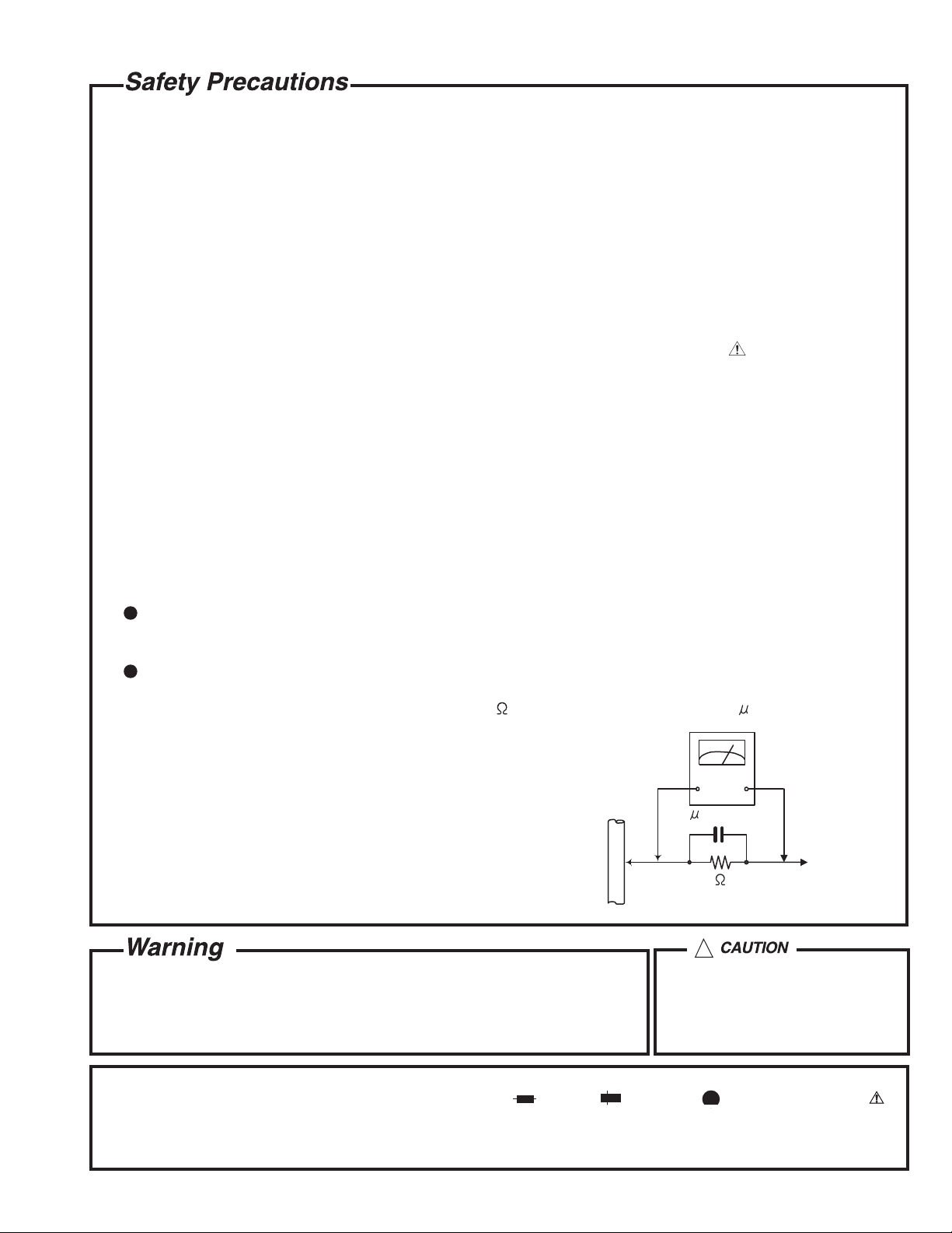
Alternate check method
Plug the AC line cord directly into the AC outlet. Use an AC voltmeter having, 1,000 ohms per volt or more
sensitivity in the following manner. Connect a 1,500 10W resistor paralleled by a 0.15 F AC-type capacitor
between an exposed metal part and a known good earth ground.
Measure the AC voltage across the resistor with the AC
voltmeter.
Move the resistor connection to each exposed metal part,
particularly any exposed metal part having a return path to
the chassis, and meausre the AC voltage across the resistor.
Now, reverse the plug in the AC outlet and repeat each
measurement. Voltage measured any must not exceed 0.75 V
AC (r.m.s.). This corresponds to 0.5 mA AC (r.m.s.).
0.15 F AC TYPE
1500 10W
AC VOLTMETER
(Having 1000
ohms/volts,
or more sensitivity)
Place this
probe on
each exposed
metal part.
Good earth ground
!
1. This equipment has been designed and manufactured to meet international safety standards.
2. It is the legal responsibility of the repairer to ensure that these safety standards are maintained.
3. Repairs m ust be made in accordance with the relevant safety standards.
4. It is essential that safety critical components are replaced by approved parts.
5. If mains voltage selector is provided, check setting for local voltage.
Burrs formed during molding may
be left over on some parts of the
chassis. Therefore, pay attention to
such burrs in the case of
preforming repair of this system.
In regard with component parts appearing on the silk-screen pr inted side (parts side) of the PWB diagrams, the
parts that are printed over with black such as the resistor ( ), diode ( ) and ICP ( ) or identified by the " "
mark nearby are critical for safety.
(This regulation does not correspond to J and C version.)
1-3
Page 4
(U.K only)
1. This design of this product contains special hardware and many circuits and components specially
for safety purposes. For continued protection, no changes should be made to the original
design unless authorized in writing by the manufacturer. Replacement parts must be identical to
those used in the original circuits.
2. Any unauthorised design alterations or additions will void the manufacturer's guarantee ; furthermore the
manufacturer cannot accept responsibility f or personal injury or property damage resulting therefrom.
3. Essential safety critical components are identified by ( ) on the Parts List and by shading on the
schematics, and must never be replaced by parts other than those listed in the manual. Please note
however that many electrical and mechanical parts in the product have special safety related
characteristics. These characteristics are often not evident from visual inspection. Parts other than
specified by the manufacturer may not have the same safety characteristics as the recommended
replacement parts shown in the Parts List of the Service Manual and may create shock, fire, or
other hazards.
4. The leads in the products are routed and dressed with ties, clamps, tubings, barriers and the
like to be separated from live parts, high temperature parts, moving parts and/or sharp edges
for the prevention of electric shock and fire hazard. When service is required, the original lead
routing and dress should be observed, and it should be confirmed that they have been returned
to normal, after re-assembling.
1. Service should be performed by qualified personnel only.
2. This equipment has been designed and manufactured to meet international safety standards.
3. It is the legal responsibility of the repairer to ensure that these safety standards are maintained.
4. Repairs must be made in accordance with the relevant safety standards.
5. It is essential that safety critical components are replaced by approved parts.
6. If mains voltage selector is provided, check setting for local voltage.
!
Burrs formed during molding may be left over on some parts of the chassis. Therefore,
pay attention to such burrs in the case of preforming repair of this system.
1-4
Page 5

Preventing static electricity
Electrostatic discharge (ESD), which occurs when static electricity stored in the body, fabric, etc. is discharged,
can destroy the laser diode in the traverse unit (optical pickup). Take care to prevent this when performing repairs.
Grounding to prevent damage by static electricity
Static electricity in the work area can destroy the optical pickup (laser diode) in devices such as mechanism unit.
Be careful to use proper grounding in the area where repairs are being performed.
1. Ground the workbench
Ground the workbench by laying conductive material (such as a conductive sheet) or an iron plate over
it before placing the traverse unit (optical pickup) on it.
2. Ground yourself
Use an anti-static wrist strap to release any static electricity built up in your body.
(caption)
Anti-static wrist strap
Conductive material
(conductive sheet) or iron plate
3. Handling the optical pickup
1. In order to maintain quality during transport and before installation, both sides of the laser diode on the
replacement optical pickup are shorted. After replacement, return the shorted parts to their original condition.
(Refer to the text.)
2. Do not use a tester to check the condition of the laser diode in the optical pickup. The tester's internal power
source can easily destroy the laser diode.
Handling the traverse unit (optical pickup)
1. Do not subject the traverse unit (optical pickup) to strong shocks, as it is a sensitive, complex unit.
2. Cut off the shorted part of the flexible cable using nippers, etc. after replacing the optical pickup. For specific
details, refer to the replacement procedure in the text. Remove the anti-static pin when replacing the traverse
unit. Be careful not to take too long a time when attaching it to the connector.
3. Handle the flexible cable carefully as it may break when subjected to strong force.
4. It is not possible to adjust the semi-fixed resistor that adjusts the laser power. Do not turn it
1-5
Page 6

Block Diagram
FM ANT
R/P HEAD
FM RF
BPF FM F/E , IF/DET/MPX
AM ANT
VD103
TU L&R CH.
R/P SW.
FM OSC.
IC101 LA1823
AM RF/IF/DET.
AM OSC.
REC L&R CH.
IC102 LC72131
PLL
TU-5V
REG.
ERASE HEAD
R/P SW.
TAPE L&R CH.
IC501 LC75342
SIGNAL SLECT SW.
EQ./E. VOL.
IC201 TA8142AP
R/P PRE.AMP.
P/B L&R CH.
R/P SW.
CD L&R CH.
LCD
REC L&R CH.
CD SW.
TU SW.
1-6
Page 7

DISC
PICKUP
SPINDLE
M
M
SLED
MOTOR
IC701
LC587008
(u-COM.)
MOTOR
IC901
LA9242M
(ASP.)
IC903 LA6541D
MOTOR/ACTUATOR
DRIVER
KEY
IC902
LC78622E
(DSP.)
Q907
CD DOOR
LEAF SW.
Q704
LAMP
5V REG.
IC401
8V REG.
P-CON.
L&R CH.
DC SUP.
SW.
CASS.DECK
LEAF SW.
M
DECK
MOTOR
BASS CUT
JOG.VOL.
IC301 TA8227P
POWER AMP.
RECTIFIER
L. SPEAKER
R. SPEAKER
AC INPUT
1-7
Page 8

Schematic Diagrams
1-8
Page 9

1-9
Page 10

1-10
Page 11

1-11
Page 12

JVC Euorpe Limited
JVC House
JVC Budiness Park 12 Priestley Way, London NW2 7BA United Kingdom
(No.MB063)
2003/11
 Loading...