

Page 1
SERVICE MANUAL
CD PORTABLE SYSTEM
MB27920046
RC-EX30B
SERVICE POLICY
No service part is available for this model.
Exchange only.
P
RO
GR
AM
/
CL
OCK
S
ET
PR
ES
E
T
D
O
W
P
R
E
S
E
T
N
U
P
H
B
S
/
P
R
E
S
ET
E
STANDBY/ON
DISPLAY
HBS/
PRESET EQ
FM MODE
/BEAT CUT
UP
PRESET
DOWN
CD/
TUNER/
RANDOM
BAND
123
456
789
0
PROGRAM/
INTRO
CLOCK SET
REPEAT
MUTING
TAPE
OVER
+
GROUP
–
VOLUME
G
R
O
U
TAP
P
E
RANDOM
CD
TUNER
REMOTE
SENSOR
B
AN
D
PUSH
DISPLAY
E
S
AU
Y/P
PLA
Q
OP
ST
RM-SRCEX30J REMOTE CONTROL
Area suffix
A ------------------------ Australia
B ------------------------------ U.K.
E ---------- Continental Europe
EN ----------- Northern Europe
EV ------------- Eastern Europe
TABLE OF CONTENTS
1 PRECAUTION. . . . . . . . . . . . . . . . . . . . . . . . . . . . . . . . . . . . . . . . . . . . . . . . . . . . . . . . . . . . . . . . . . . . . . . . . 1-3
2 SPECIFIC SERVICE INSTRUCTIONS . . . . . . . . . . . . . . . . . . . . . . . . . . . . . . . . . . . . . . . . . . . . . . . . . . . . . . 1-4
3 DISASSEMBLY . . . . . . . . . . . . . . . . . . . . . . . . . . . . . . . . . . . . . . . . . . . . . . . . . . . . . . . . . . . . . . . . . . . . . . . 1-5
4 ADJUSTMENT . . . . . . . . . . . . . . . . . . . . . . . . . . . . . . . . . . . . . . . . . . . . . . . . . . . . . . . . . . . . . . . . . . . . . . . 1-14
5 TROUBLESHOOTING . . . . . . . . . . . . . . . . . . . . . . . . . . . . . . . . . . . . . . . . . . . . . . . . . . . . . . . . . . . . . . . . . 1-15
COPYRIGHT © 2004 Victor Company of Japan, Limited
No.MB279
2004/6
Page 2
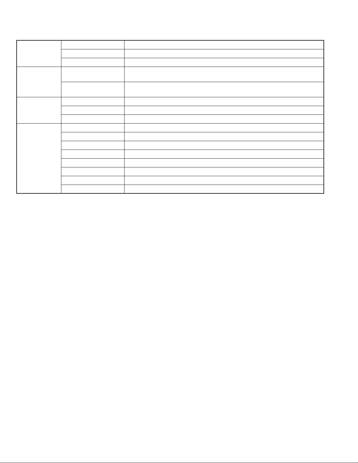
SPECIFICATION
CD player CD capacity 1 CD
Signal-to-noise ratio 75 dB
Dynamic range 60 dB
Tuner Frequency range FM 87.5 - 108.0 MHz
AM 522 - 1 629 kHz
Antennas Telescopic antenna for FM
Ferrite core antenna for AM
Cassette deck Frequency response 60 Hz - 10 000 Hz
Wow & flutter 0.15% (WRMS)
Fast wind time Approx. 150 sec. (C-60 cassette)
General Speakers 9 cm cone × 2
Speaker impedance 4 Ω
Output power 4 W (2 W + 2 W) at 4 Ω (10% THD)
Output terminals PHONES × 1
Power supply AC 230 V , 50 Hz DC 9 V (R20 (SUM-1)/D (13D)-size batteries × 6)
Power consumption 18 W (at operation) 3 W (on standby)
Dimensions 420 mm × 178 mm × 250 mm (W/H/D)
Mass Approx. 3.2 kg (without batteries)
Design and specifications are subject to change without notice.
1-2 (No.MB279)
Page 3

SECTION 1
PRECAUTION
This service manual does not describe PRECAUTION.
(No.MB279)1-3
Page 4

SECTION 2
SPECIFIC SERVICE INSTRUCTIONS
This service manual does not describe SPECIFIC SERVICE INSTRUCTIONS.
1-4 (No.MB279)
Page 5
SECTION 3
DISASSEMBLY
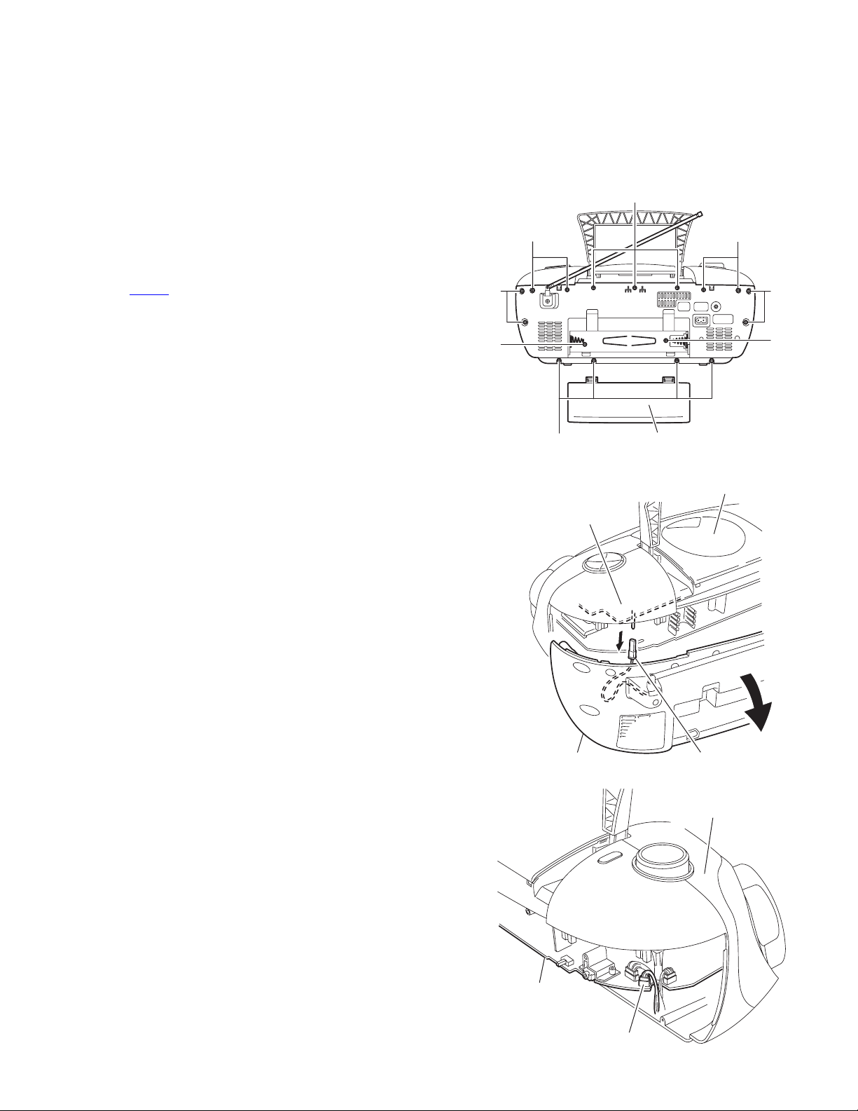
3.1 Main body
3.1.1 Removing the rear cover assembly section
(See Fig.1 to 3)
(1) Remove the eight screws A, the three screws B and the
four screws C attaching the rear cover assembly on the
back of the body.
(2) Remove the battery cover on the back of the body and re-
move the two screws D attaching the rear cover assembly.
(3) Move the rear cover assembly in the direction of the arrow
and remove. At this time, disconnect the wire from connector CN406
and FM-ANT on the main board.
A
C
B
C
A
D
A
Tuner board
D
Battery cover
Fig.1
Top cover assembly
Rear cover assembly
Main board
FM-ANT
Fig.2
Front panel assembly
CN406
Fig.3
(No.MB279)1-5
Page 6
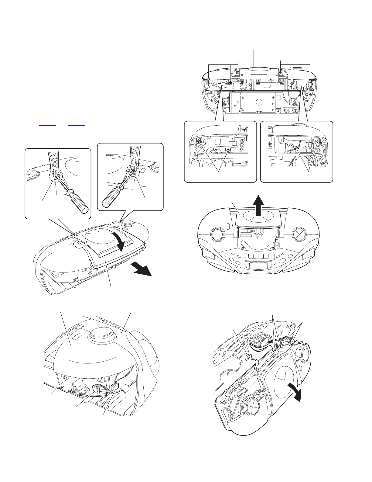
3.1.2 Removing the top cover assembly section and the front panel assembly section
(See Fig.4 to 8)
• Prior to performing the following procedure, remove the rear
cover assembly.
(1) Release the tab a of the handle using a screwdriver. Return
the handle below and pull out in the direction of the arrow.
(2) Disconnect the wire from connector CN404
nector on the main board.
(3) Remove the six screws E and the two screws F attaching
the top cover.
(4) Draw out the top cover assembly from the front panel as-
sembly section backward.
(5) Disconnect the wire from connector CN501
the main board, and disconnect the card wire from connector CN507
(6) Disconnect the wire from board connector CON301 of the
cassette mechanism assembly.
and CN508.
and 4pin con-
and CN506 on
Top cover assembly
E
E
EE
Fig.6
tab a
Top cover assembly
Handle
Fig.4
Front panel assembly
tab a
CD door
Fig.7
Cassette mechanism board
CON301
F
Main board
CN508,CN507
Main board
CN501,CN506
Main board
1-6 (No.MB279)
CN404
4pin connector
Fig.5
Fig.8
Page 7
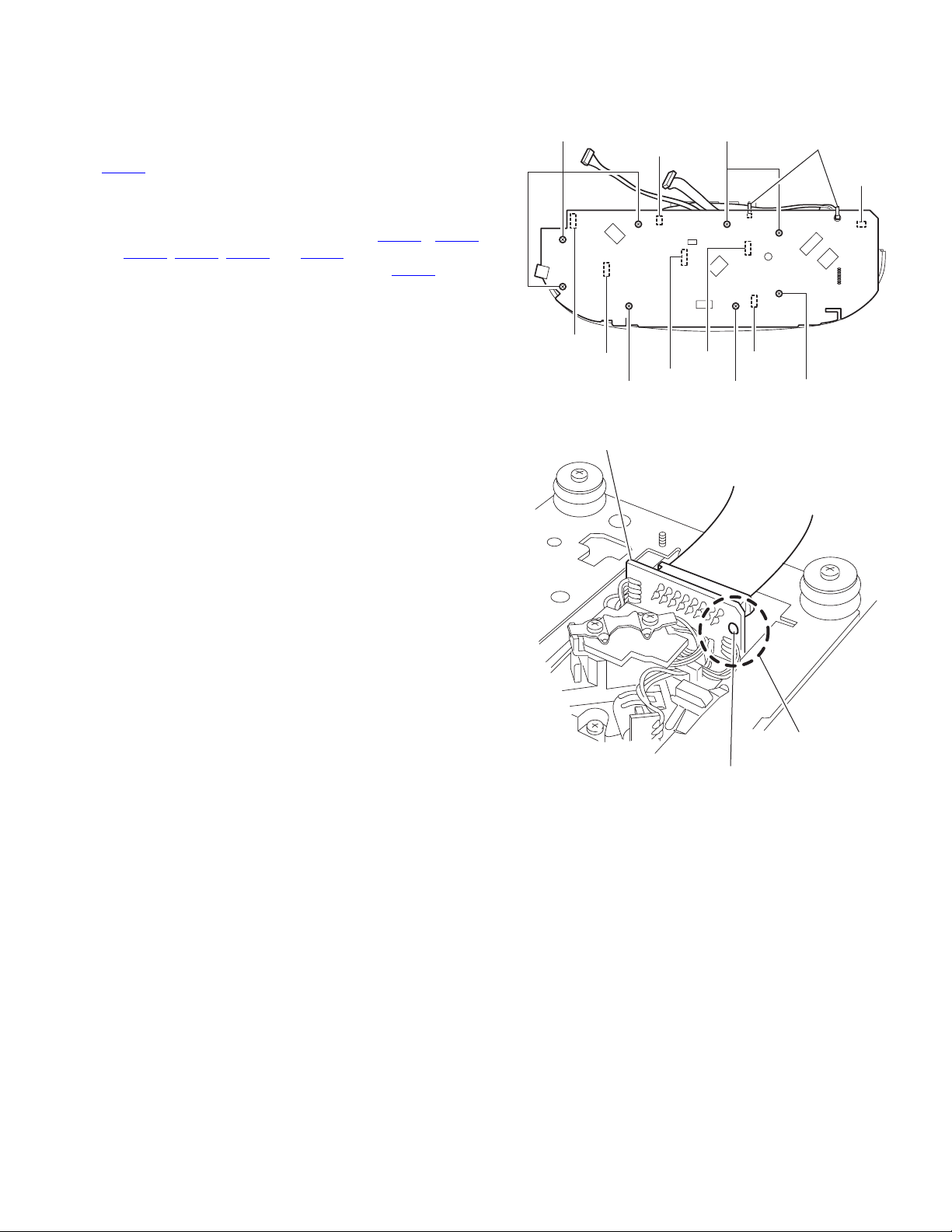
3.1.3 Removing the main body
(See Fig.9, 10)
Caution:
Make sure to solder the short-circuit point on the CD servo
board before disconnecting the card wire from connector
on the main board and from the CD servo board. If you
CN201
don't observe this instruction, the pickup may be damaged.
(1) Remove the eight screws G attaching the main board on
the top cover assembly.
(2) Disconnect the wire from connector CN501
, CN202, CN401 and CN504 on the main board.
CN511
(3) Disconnect the card wire from connector CN201 on the
main board.
Caution:
If necessary, cut the band.
, CN502,
G
CN501
CN504
CD servo board
CN502
CN201
CN202
Fig.9
G
Band
CN511
CN401
GGG
Unsolder
Fig.10
Short-circuit point
(No.MB279)1-7
Page 8
3.1.4 Tuner board
(See Fig.11)
• Prior to performing the following procedure, remove the main
board.
(1) Remove the three screws H attaching the tuner board.
3.1.5 Removing the top switch board
(See Fig.12)
• Prior to performing the following procedure, remove the main
board and the tuner board.
(1) Remove the four screws J attaching the top switch board.
H
Tuner board
H
Fig.11
Top switch board
J
1-8 (No.MB279)
J
Fig.12
Page 9
3.1.6 Removing the volume board and the power switch board
(See Fig.13 to 16)
• Prior to performing the following procedure, remove the main
board.
(1) Remove the three screws K attaching the volume board.
(2) Pull out the volume board from the volume knob.
(3) Remove the four screws L attaching the cover on the side
of the power switch.
(4) Release the three tabs b of the cover on the side of the
power switch.
(5) Remove the three screws M attaching the power switch
board to the cover.
Caution:
If necessary, unsolder the solder points.
Ta b b
Volume board
K
Volume knob
Top cover assembly
K
Solder point
Fig.13
Switch board
Side top cover
Side top cover
L
Fig.15
Fig.16
M
Switch board
Solder point
M
Power switch board
Volume board
Solder point
K
K
Fig.14
(No.MB279)1-9
Page 10

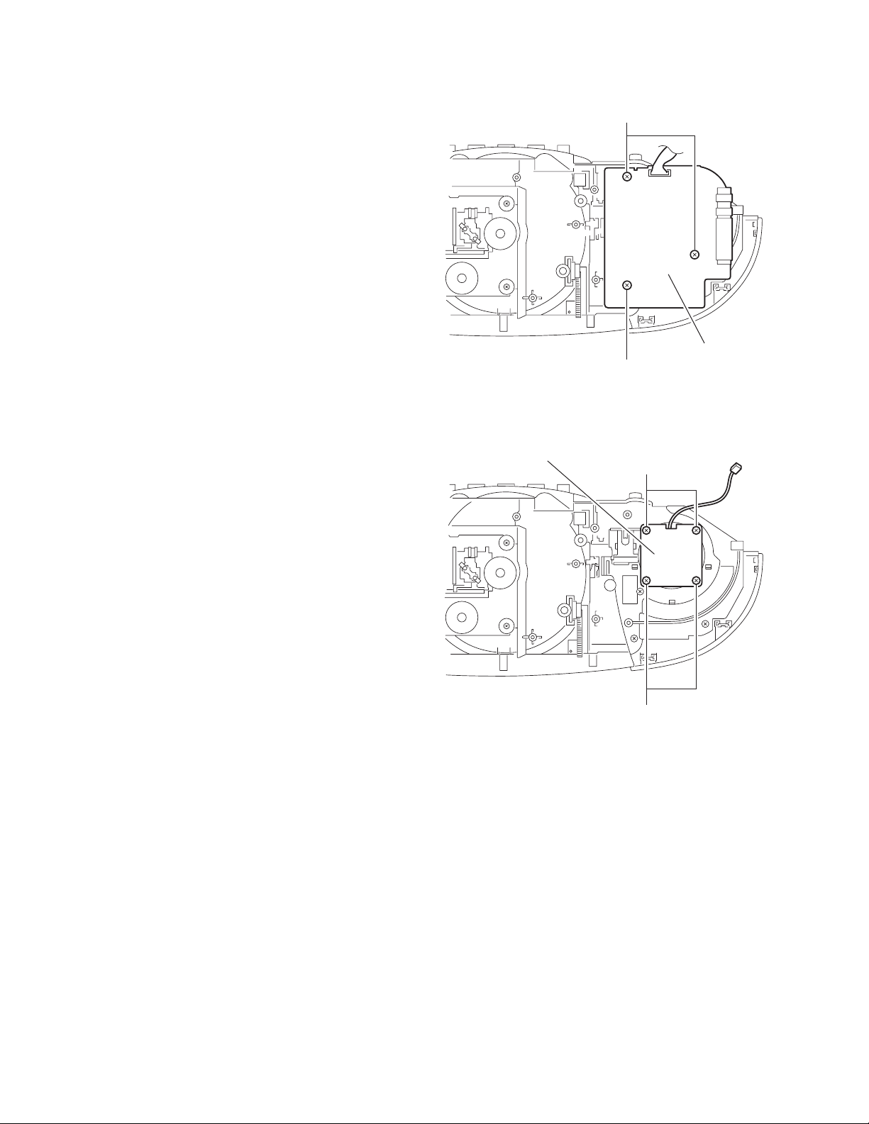
3.1.7 Removing the CD mechanism assembly
(See Fig.17)
• Prior to performing the following procedure, remove the main
board.
(1) Remove the four screws N attaching the CD mechanism
assembly.
CD mechanism
assembly
Top cover assembly
N
N
Fig.17
1-10 (No.MB279)
Page 11

3.1.8 Removing the cassette mechanism assembly
(See Fig.18 ~ 21)
(1) Remove the four screws P attaching the cassette mecha-
nism cover.
(2) Remove the four screws Q attaching the cassette mecha-
nism assembly.
(3) Push Eject button to open the cassette door.
(4) Pull out the cassette mechanism assembly in the direction
of arrow.
(5) Remove the six screws R attaching the operation board.
Cassette mechanism cover
PP
Fig.18
Cassette mechanism assembly
QQ
Fig.19
Cassette door
R
EJECT button
Fig.20
Button
Cassette mechanism assembly
Fig.21
(No.MB279)1-11
Page 12

3.1.9 Removing the LCD & switch board
(See Fig.22)
• Prior to performing the following procedure, remove the cas-
sette mechanism assembly.
(1) Remove the eight screws S attaching the LCD & switch
board.
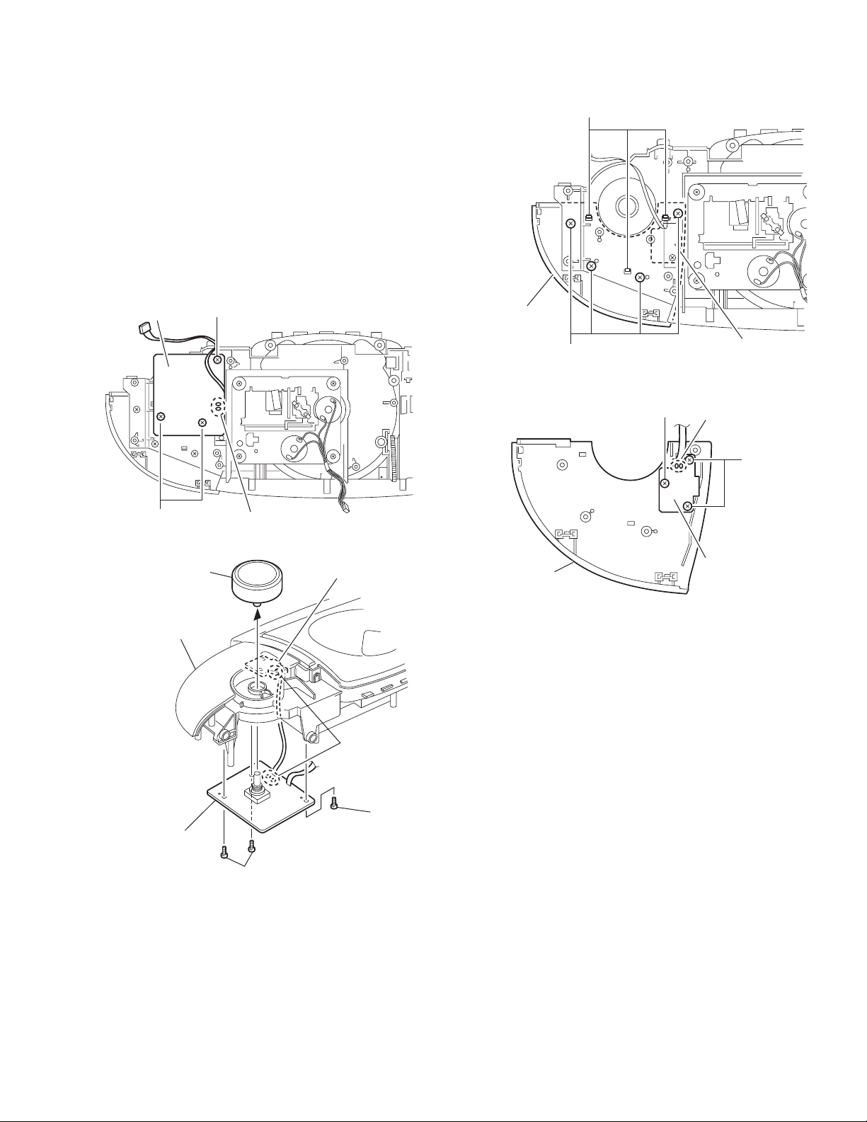
3.1.10 Removing the speaker
(SeeFig.23)
(1) Remove the six screws T attaching the speaker bracket.
(2) Peel the tape and glue off attaching the speaker cord.
Caution:
The band comes off when you remove the speaker.
S
LCD & switch board
Fig.22
Speaker Speaker
S
Band
T
Ta pe
Glue
Speaker bracket
Fig.23
Tape
T
1-12 (No.MB279)
Page 13

3.1.11 Removing the power transformer and the battery board
(See Fig.24, 25)
(1) Remove the two screws U attaching the power transform-
er.
(2) Remove the two screws V attaching the power socket.
(3) Remove the support board attaching the battery board.
(4) Release the tab d setting the battery board and pull out the
battery board.
(5) If necessary, unsolder the solder points.
Caution:
When you remove the power transformer, the band setting the
cord to the screw hole comes off.
U
Battery board
V
Support board
Fig.24
Ta pe
Solder point
Battery board
Ta b d
Fig.25
(No.MB279)1-13
Page 14

SECTION 4
ADJUSTMENT
This service manual does not describe ADJUSTMENT.
1-14 (No.MB279)
Page 15

5.1 Block diagram
SECTION 5
TROUBLESHOOTING
DRAM
HY51181
FLASH
ROM
MX29F040
REMOTE
CONTROL
KEY BOARD
REMOTE
SENSOR
MCU
4K76
LCD
PLL
TC9257
SOURCE
SELECTOR
TC9422
TUNER
TA2149
SPEAKER
PHONE
POWER AMP
TA8227
ESS 3890
DSP
TC9462
CD SERVO
TA2092
D/A
P18211
HCF4052
CD
PICKUP
TAPE
AN7312
DC SUPPLY
BATT 6x1.5V
POWER
SUPPLY
AC IN
CD RF AMP
TA2153
(No.MB279)1-15
Page 16

5.2 Standard schematic diagrams
5.2.1 Amp section
1-16 (No.MB279)
Page 17

(No.MB279)1-17
Page 18

5.2.2 Micon section
1-18 (No.MB279)
Page 19

(No.MB279)1-19
Page 20

5.2.3 CD section
1-20 (No.MB279)
Page 21

(No.MB279)1-21
Page 22

5.2.4 MP3 section
1-22 (No.MB279)
Page 23

(No.MB279)1-23
Page 24

5.2.5 Cassette section
1-24 (No.MB279)
Page 25

(No.MB279)1-25
Page 26

5.2.6 Tuner section
1-26 (No.MB279)
Page 27

(No.MB279)1-27
Page 28

Victor Company of Japan, Limited
AV & MULTIMEDIA COMPANY AUDIO/VIDEO SYSTEMS CATEGORY 10-1,1chome,Ohwatari-machi,Maebashi-city,371-8543,Japan
(No.MB279)
Printed in Japan
WPC
 Loading...