

Page 1
SERVICE MANUAL
CD PORTABLE SYSTEM
MB27520046
RC-EX10S,RC-EX10B,RC-EX10A
SERVICE POLICY
No service part is available for this model.
Exchange only.
A ------------------------ Australia
B ------------------------------ U.K.
E ---------- Continental Europe
EN ----------- Northern Europe
EV ------------- Eastern Europe
B ------------------------------ U.K.
E ---------- Continental Europe
EN ----------- Northern Europe
EV ------------- Eastern Europe
RC-EX10S
Area suffix
RC-EX10B
RC-EX10A
Area suffix
TABLE OF CONTENTS
1 PRECAUTION. . . . . . . . . . . . . . . . . . . . . . . . . . . . . . . . . . . . . . . . . . . . . . . . . . . . . . . . . . . . . . . . . . . . . . . . . 1-3
2 SPECIFIC SERVICE INSTRUCTIONS . . . . . . . . . . . . . . . . . . . . . . . . . . . . . . . . . . . . . . . . . . . . . . . . . . . . . . 1-4
3 DISASSEMBLY . . . . . . . . . . . . . . . . . . . . . . . . . . . . . . . . . . . . . . . . . . . . . . . . . . . . . . . . . . . . . . . . . . . . . . . 1-5
4 ADJUSTMENT . . . . . . . . . . . . . . . . . . . . . . . . . . . . . . . . . . . . . . . . . . . . . . . . . . . . . . . . . . . . . . . . . . . . . . . 1-12
5 TROUBLESHOOTING . . . . . . . . . . . . . . . . . . . . . . . . . . . . . . . . . . . . . . . . . . . . . . . . . . . . . . . . . . . . . . . . . 1-13
COPYRIGHT © 2004 Victor Company of Japan, Limited
No.MB275
2004/6
Page 2
SPECIFICATION
CD player CD capacity 1 CD
Dynamic range 60 dB
Signal-to-noise ratio 75 dB
Tuner Frequency range FM 88 - 108 MHz
AM 540 - 1 600 kHz
Antenna Telescopic antenna for FM
Ferrite core antenna for AM
Cassette deck section Frequency range 60 hZ - 10 000Hz
Wow and flutter 0.15% (WRMS)
General Speaker 9 cm cone × 2 (4 Ω)
Power output 2 W + 2 W at 4 Ω (10 % THD) (IEC 268-3)
Putput terminals Phones × 1 (3.5mm, stereo)
Power supply AC 230 V, 50 Hz
DC 9 V ("R20 (SUM-1)/D (13D)" × 6 )
Power consumption 12 W (at operation), 3 W (on standby)
Dimensions 420 mm (W) × 178 mm (H) × 250 mm (D)
Mass Approx. 3.2 kg (without batteries)
Design and specifications are subject to change without notice.
1-2 (No.MB275)
Page 3

SECTION 1
PRECAUTION
This service manual does not describe PRECAUTION.
(No.MB275)1-3
Page 4

SECTION 2
SPECIFIC SERVICE INSTRUCTIONS
This service manual does not describe SPECIFIC SERVICE INSTRUCTIONS.
1-4 (No.MB275)
Page 5
SECTION 3
DISASSEMBLY
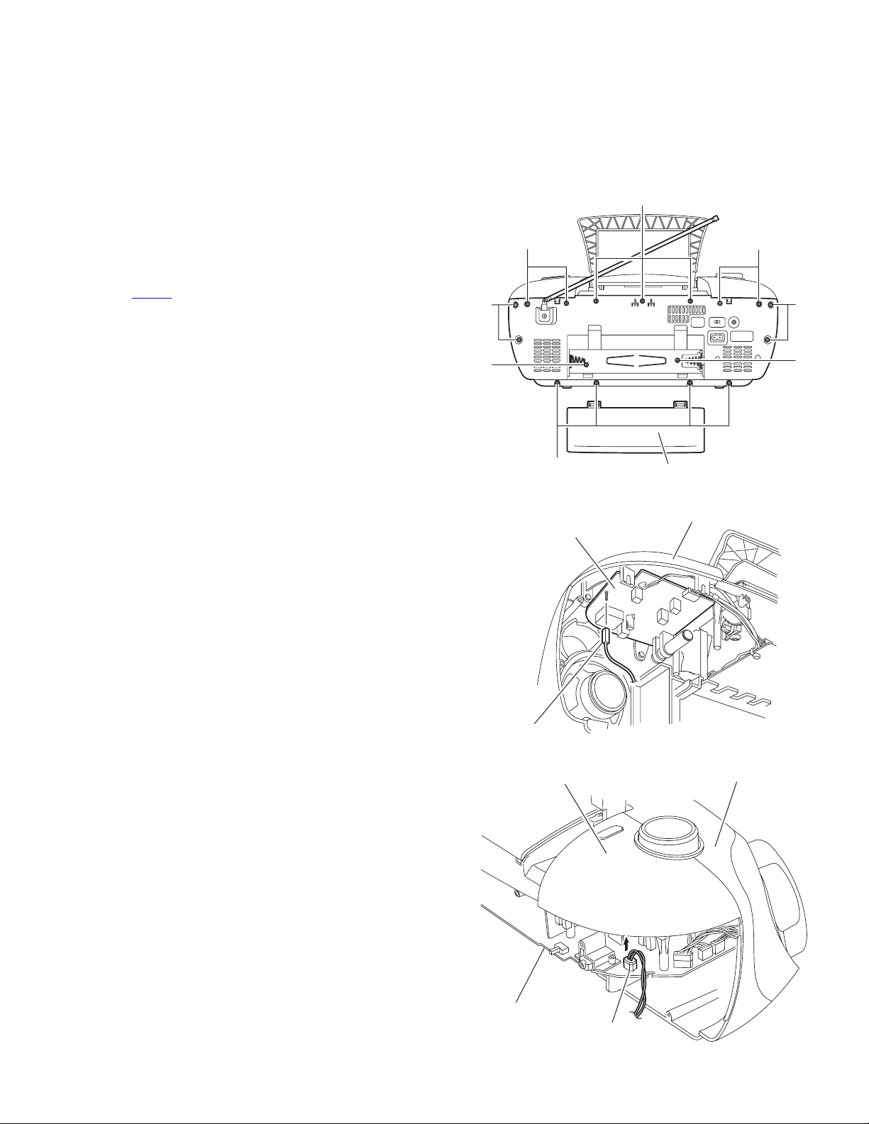
3.1 Main body
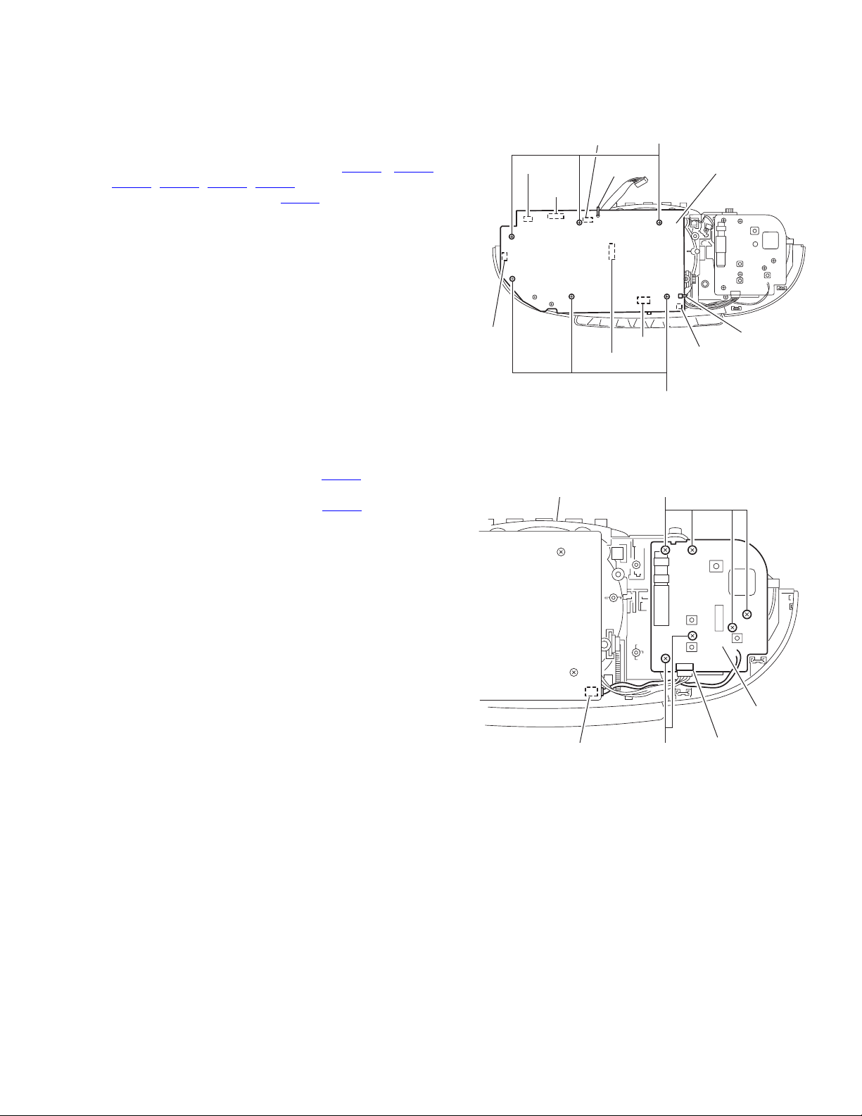
3.1.1 Removing the rear cover assembly section
(See Fig.1 to 3)
(1) Remove the eight screws A, the three screws B and the
four screws C attaching the rear cover assembly on the
back of the body.
(2) Remove the battery cover on the back of the body and re-
move the two screws D attaching the rear cover assembly.
(3) Move the rear cover assembly in the direction of the arrow
and remove. At this time, disconnect the wire from connector CN405
board.
on the main board, and FM-ANT on the tuner
A
C
B
C
A
D
Tuner board
FM-ANT
Top cover assembly
A
D
Battery cover
Fig.1
Top cover assembly
Fig.2
Front panel assembly
Main board
CN405
Fig.3
(No.MB275)1-5
Page 6
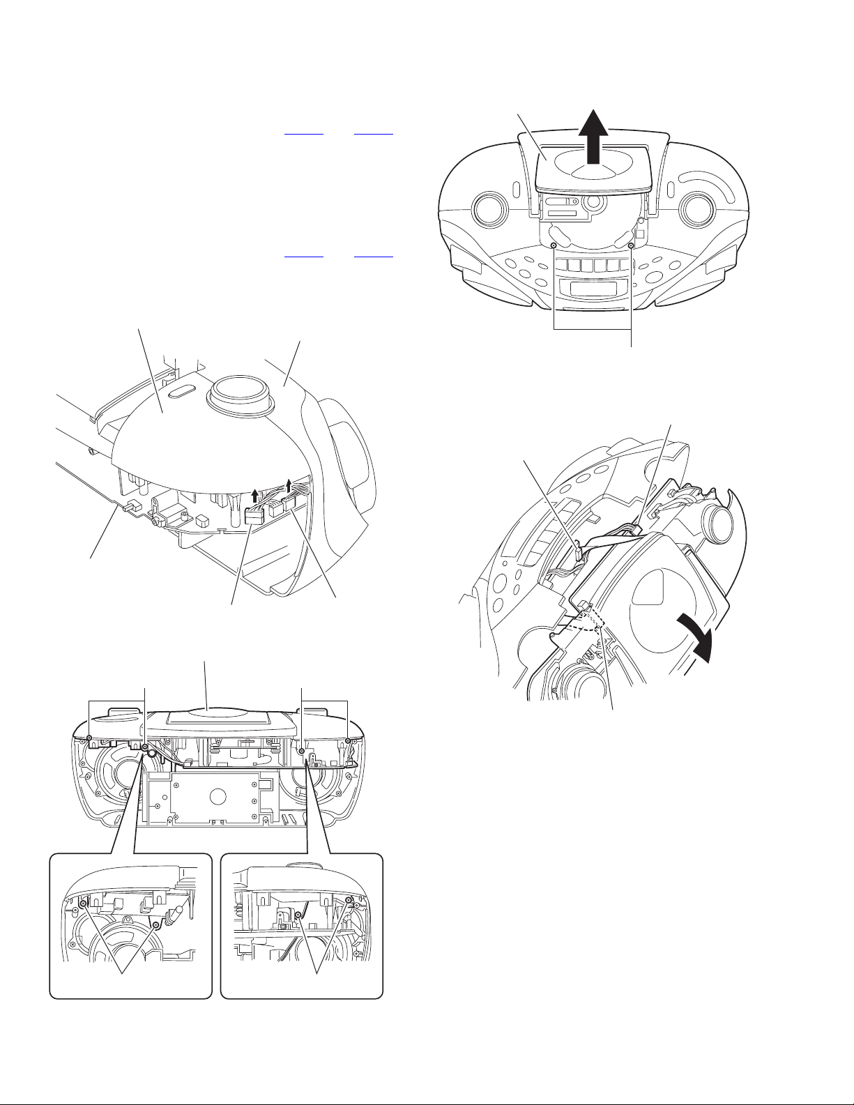
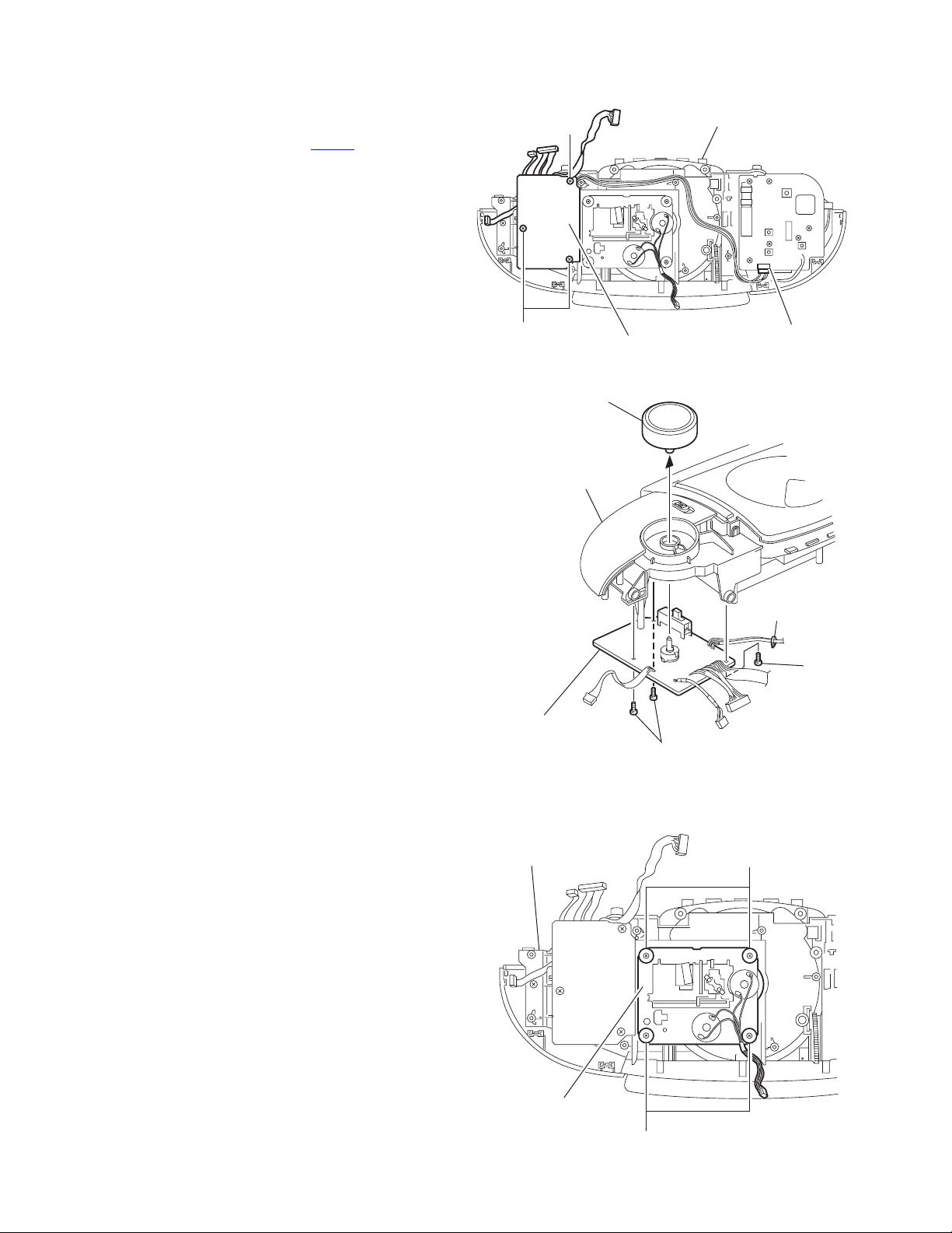
3.1.2 Removing the top cover assembly section and the front panel assembly section
(See Fig.4 to 7)
• Prior to performing the following procedure, remove the rear
cover assembly.
(1) Disconnect the wire from connectors CN404 and CN408
on the main board.
(2) Remove the four screws E attaching the top cover assem-
bly.
(3) Open the door and remove the two screws F attaching the
top cover assembly.
(4) Draw out the top cover assembly from the front panel as-
sembly section backward.
(5) Disconnect the wire from connectors CN403
on the main board.
(6) Disconnect the wire from connector CON301 on the cas-
sette mechanism board.
Top cover assembly
Front panel assembly
and CN204
Cassette mechanism board
CD door
CON301
F
Fig.6
Main board
CN403
Main board
CN404
Fig.4
Top cover assembly
E
CN408
E
Main board
CN204
Fig.7
E
1-6 (No.MB275)
E
Fig.5
Page 7
3.2 Top cover assembly section
3.2.1 Removing the main body
(See Fig.8)
(1) Remove the six screws G attaching the main board on the
top cover assembly.
(2) Cut off the band attaching the wire.
(3) Disconnect the wire from connector CN406
, CN401, CN407, CN202 on the main board, and
CN403
disconnect the card wire from CN201.
, CN402,
CN401
CN402
CN403
Band
G
Main board
3.2.2 Removing the tuner board
(See Fig.9)
(1) Disconnect the wire from connector CN101
board.
(2) Disconnect the wire from connector CN406
board.
(3) Remove the six screws H attaching the tuner board.
on the tuner
on the main
CN407
Top cover assembly
CN202
CN201
Band
CN406
G
Fig.8
H
Tuner board
Main board
CN406
Fig.9
H
CN101
(No.MB275)1-7
Page 8
3.2.3 Removing the volume board
(See Fig.10, 11)
• Prior to performing the following procedure, remove the main
board.
(1) Disconnect the wire from connector CN101 on the tuner
board.
(2) Remove the three screws J attaching the volume board.
(3) Pull out the volume knob from the volume board.
Caution:
The band attaching the wire on the volume board comes off.
J
Top cover assembly
3.2.4 Removing the CD mechanism assembly
(See Fig.12)
• Prior to performing the following procedure, remove the main
board.
(1) Remove the four screws K attaching the CD mechanism
assembly.
J
Volume knob
Top cover assembly
Volume board
Top cover assembly
Volume board
Tuner board
CN101
Fig.10
Band
J
J
Fig.11
K
1-8 (No.MB275)
CD mechanism
assembly
K
Fig.12
Page 9

3.3 Front panel assembly section
3.3.1 Removing the cassette mechanism assembly
(See Fig.13 to 16)
(1) Remove the four screws L attaching the cassette mecha-
nism cover.
(2) Remove the four screws M attaching the cassette mecha-
nism assembly.
(3) Push Eject button to open the cassette door.
(4) Pull out the cassette mechanism assembly in the direction
of arrow.
(5) Remove the six screws N attaching the button.
Cassette mechanism cover
LL
Fig.13
Cassette mechanism assembly
Cassette door
N
MM
Fig.14
EJECT button
Fig.15
Button
Cassette mechanism assembly
Fig.16
(No.MB275)1-9
Page 10

3.3.2 Removing the LCD & switch board
(See Fig.17)
• Prior to performing the following procedure, remove the cas-
sette mechanism assembly.
(1) Remove the six screws P attaching the LCD & switch
board.
3.3.3 Removing the speaker
(SeeFig.18)
(1) Remove the six screws Q attaching the speaker bracket.
(2) Peel the tape and glue off attaching the speaker cord.
Caution:
The band comes off when you remove the speaker.
P
LCD & switch board
Fig.17
Speaker Speaker
P
Band
Q
Ta pe
Glue
Speaker bracket
Fig.18
Tape
Q
1-10 (No.MB275)
Page 11

3.4 Rear cover assembly section
3.4.1 Removing the power transformer and the battery board
(See Fig.19,20)
(1) Remove the two screws R attaching the power transform-
er.
(2) Remove the two screws T attaching the power socket.
(3) Remove the support board attaching the battery board.
(4) Release the tab a setting the battery board and pull out the
battery board.
(5) If necessary, unsolder the six solder points.
T
Battery board
R
Support board
Fig.19
Ta p
Solder point
Battery board
a
Fig.20
(No.MB275)1-11
Page 12

SECTION 4
ADJUSTMENT
This service manual does not describe ADJUSTMENT.
1-12 (No.MB275)
Page 13

5.1 Block diagram
SECTION 5
TROUBLESHOOTING
LCD DISPLAY
KEY BOARD
DRIVER
BU24530-9A
CD PICKUP
SY REC
VOLUME
DBBS
TUNER
SECTION
REMOTE
CONTROL
TAPE
SECTION
SOURCE SELECT
(SLIDE SWITCH)
for CD
for TUNER
for TAPE
VOLTAGE
REGULATOR
POWER AMP
RECTIFILTER
AC/DC CONVERSE
L/R SPEAKER
HEAD PHONE
AC SUPPLY
DC SUPPLY
BATTERY 6x1.5V
(No.MB275)1-13
Page 14

5.2 Standard schematic diagrams
5.2.1 Main section
1-14 (No.MB275)
Page 15

(No.MB275)1-15
Page 16

5.2.2 CD section
1-16 (No.MB275)
Page 17

(No.MB275)1-17
Page 18

5.2.3 Cassette section
1-18 (No.MB275)
Page 19

(No.MB275)1-19
Page 20

5.2.4 Tuner section
1-20 (No.MB275)
Page 21

(No.MB275)1-21
Page 22

5.2.5 Volume section
1-22 (No.MB275)
Page 23

(No.MB275)1-23
Page 24

Victor Company of Japan, Limited
AV & MULTIMEDIA COMPANY AUDIO/VIDEO SYSTEMS CATEGORY 10-1,1chome,Ohwatari-machi,Maebashi-city,371-8543,Japan
(No.MB275)
Printed in Japan
WPC
 Loading...