

Page 1
SERVICE MANUAL
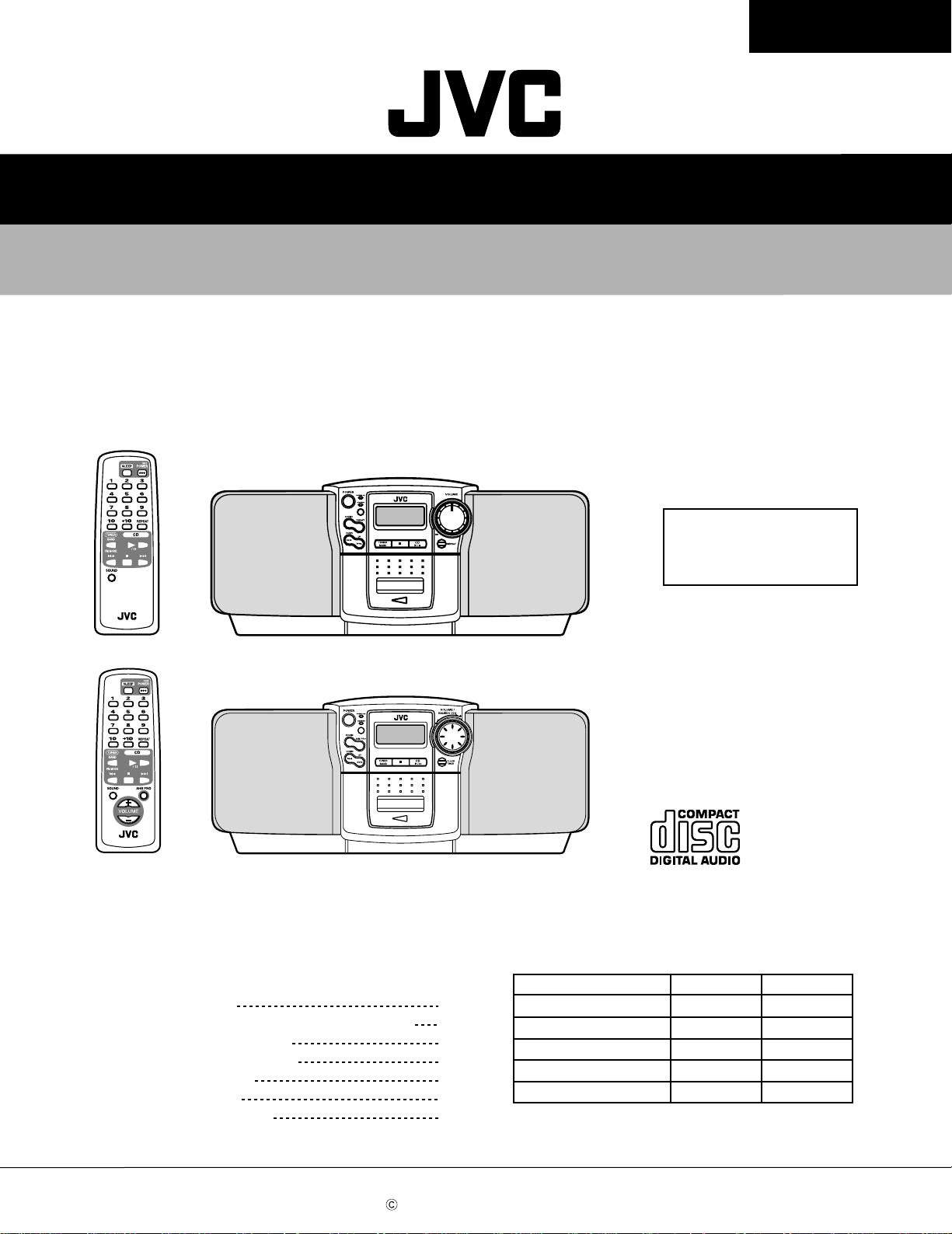
CD PORTABLE SYSTEM
RC-BZ5LB/BZ5RD
RC-BZ6BU
RC-BZ5LB/BZ5RD
RC-BZ6BU
REMOTE CONTROL RM-SRCBZ5
RC-BZ5LB/BZ5RD
REMOTE CONTROL RM-SRCBZ6
RC-BZ6BU
Contents
Safety precautions
Importance administering point on the safety
Preventing static electricity
Important for laser products
Disassembly method
Adjustment method
Description of major ICs
1-2
1-3
1-4
1-5
1-6
1-15
1-18
Areas suffix
J ---------------- U.S.A.
C ------------- Canada
Comparison table
Item
Jog dial circuit Not used Used
Back light (LCD) Not used Used
Bass boost circuit Not used Used
Power amplifier 14W 18W
Electrical volume Not used Used
RC-BZ5LB/BZ5RD
RC-BZ6BU
COPYRIGHT 2000 VICTOR COMPANY OF JAPAN, LTD.
No.20819
July. 2000
Page 2
RC-BZ5LB/BZ5RD
RC-BZ6BU
Safety precautions
1. This design of this product contains special hardware and many circuits and components specially
for safety purposes. For continued protection, no changes should be made to the original design
unless authorized in writing by the manufacturer. Replacement parts must be identical to those
used in the original circuits. Services should be performed by qualified personnel only.
2. Alterations of the design or circuitry of the product should not be made. Any design alter ations of
the product should not be made. Any design alterations or additions will void the manufacturer`s
warranty and will further relieve the manufacture of responsibility for personal injury or property
damage resulting therefrom.
3. Many electrical and mechanical parts in the products have special safety-related characteristics.
These characteristics are often not evident from visual inspection nor can the protection afforded
by them necessarily be obtained by using replacement components rated for higher voltage,
wattage, etc. Replacement parts which have these special safety characteristics are identified in
the Parts List of Service Manual. Electrical components having such features are identified by
shading on the schematics and by ( ) on the Parts List in the Service Manual. The use of a
substitute replacement which does not have the same safety characteristics as the recommended
replacement parts shown in the Parts List of Service Manual may create shock, fire, or other
hazards.
4. The leads in the products are routed and dressed with ties, clamps, tubings, barriers and the
like to be separated from live parts, high temperature parts, moving parts and/or sharp edges
for the prevention of electric shock and fire hazard. When service is required, the original lead
routing and dress should be observed, and it should be confirmed that they have been returned
to normal, after re-assembling.
5. Leakage current check (Electrical shock hazard testing)
After re-assembling the product, always perfor m an isolation check on the exposed metal parts
of the product (antenna terminals, knobs, metal cabinet, screw heads, headphone jack, control
shafts, etc.) to be sure the product is safe to operate without danger of electrical shock.
Do not use a line isolation transformer during this check.
Plug the AC line cord directly into the AC outlet. Using a "Leakage Current Tester", measure
the leakage current from each exposed metal parts of the cabinet , particularly any exposed
metal part having a return path to the chassis, to a known good earth ground. Any leakage
current must not exceed 0.5mA AC (r.m.s.)
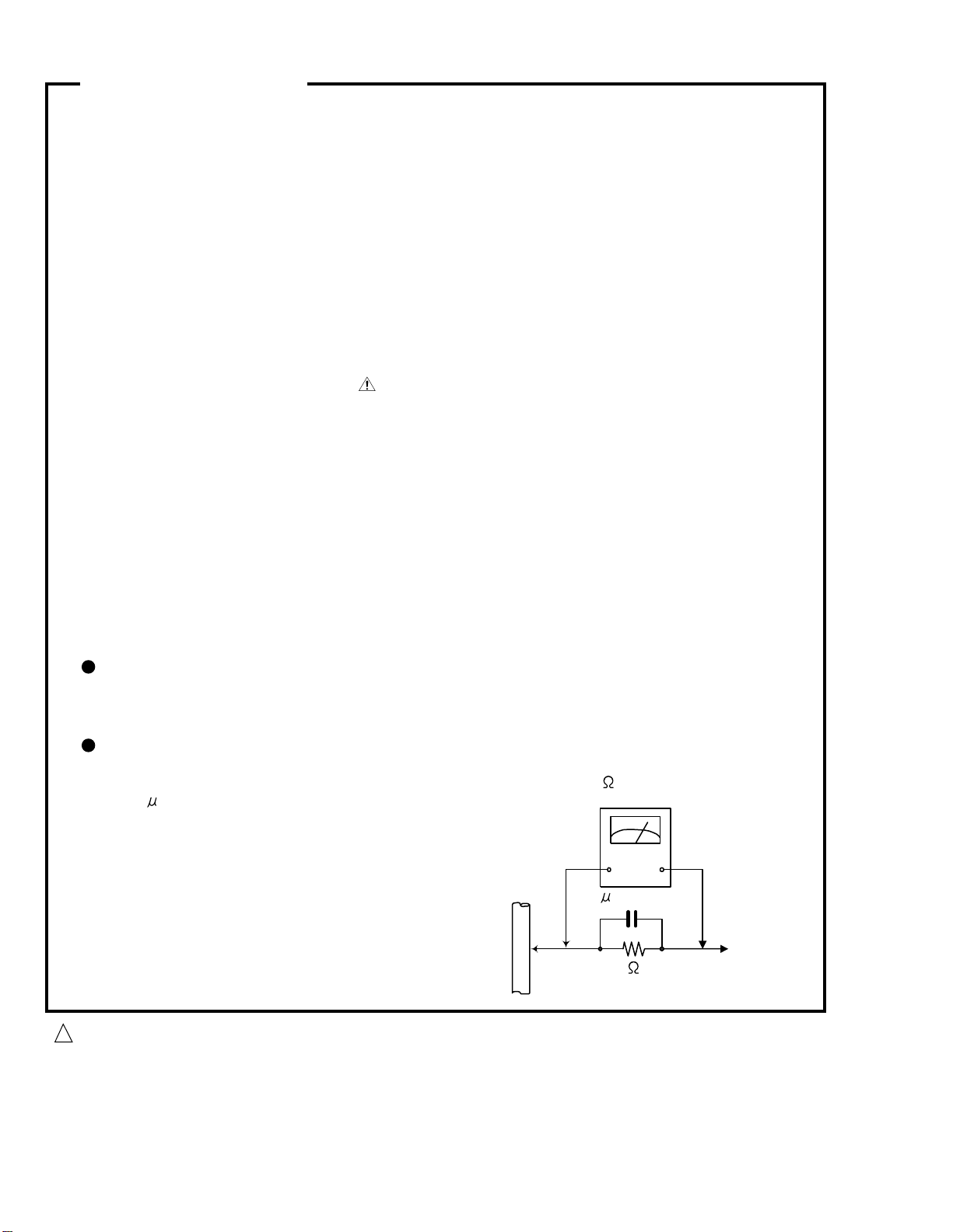
Alternate check method
Plug the AC line cord directly into the AC outlet. Use an AC voltmeter having, 1,000 ohms
per volt or more sensitivity in the following manner. Connect a 1,500 10W resistor paralleled by
a 0.15 F AC-type capacitor between an exposed
metal part and a known good earth ground.
Measure the AC voltage across the resistor with the
AC voltmeter.
Move the resistor connection to each exposed metal
part, par ticularly any exposed metal part having a
return path to the chassis, and measure the AC
voltage across the resistor. Now reverse the plug in
the AC outlet and repeat each measurement voltage
measured any must not exceed 0.75 V AC (r.m.s.).
This corresponds to 0.5 mA AC (r.m.s.).
0.15 F AC TYPE
1500 10W
Good earth ground
AC VOLTMETER
(Having 1000
ohms/volts,
or more sensitivity)
Place this
probe on
each exposed
metal part.
1-2
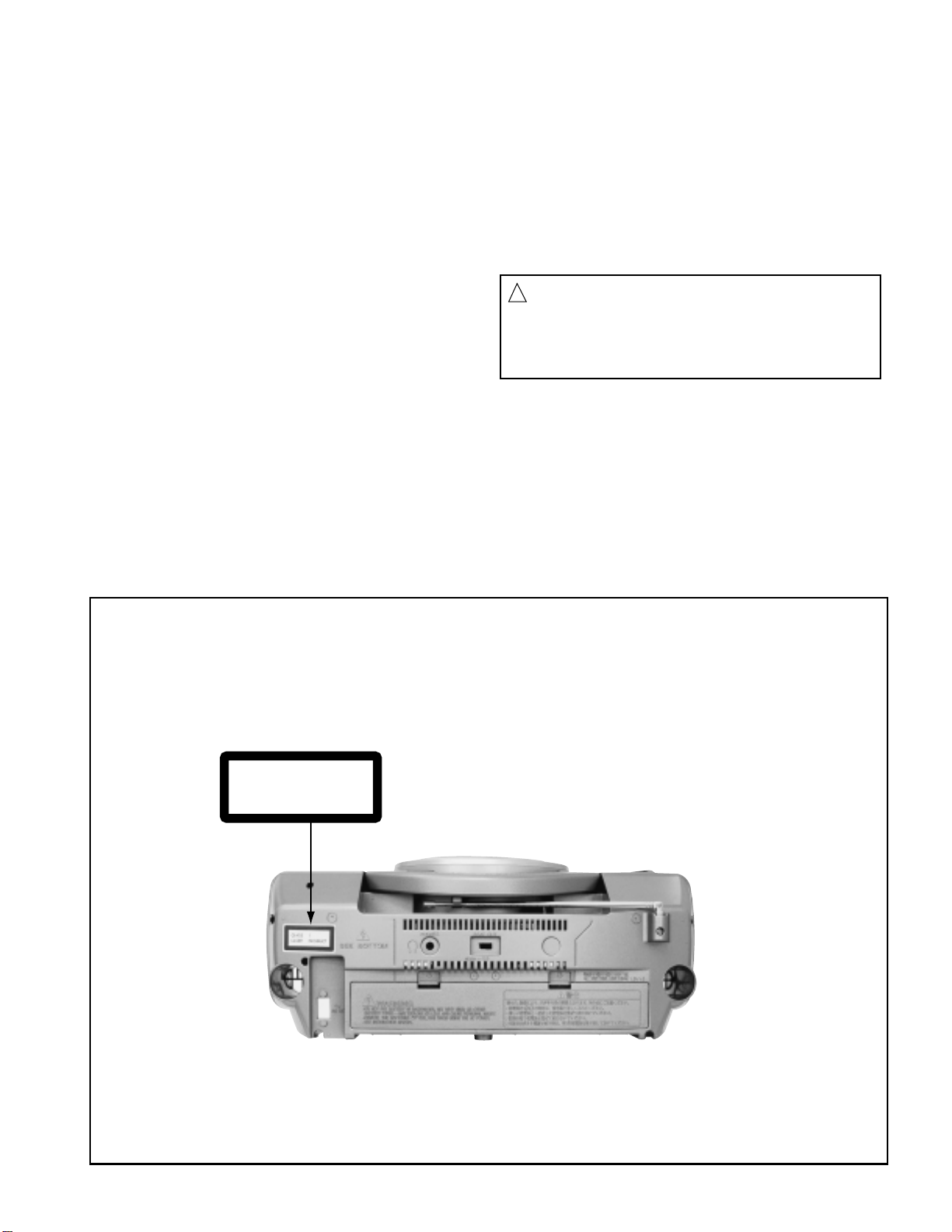
CAUTION
!
Burrs formed during molding may be left over on some parts of the chassis. Therefore,
pay attention to such burrs in the case of preforming repair of this system.
Page 3
Importance administering point on the safety
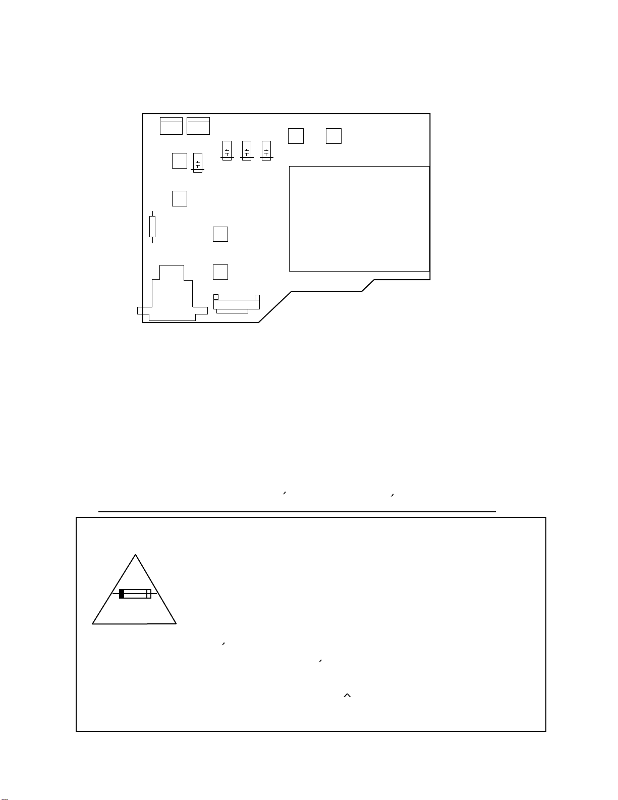
Power supply board
D902
D903
R998
CN307CN306
F903
D901
D904
F902
POWER TRANSFORMER
RC-BZ5LB/BZ5RD
RC-BZ6BU
J9
F901
Not used
S901
For USA and Canada / pour Etats - Unis d' Amerique et Canada
Caution: For continued protection against risk of
fire, replace only with same type 3A/125V for
F902 and F903. This symbol specifies type of fast
operating fuse.
Precaution: Pour eviter risques de feux, remplacez
le fusible de surete de F902 et F903 comme le
meme type que 3A/125V.
Ce sont des fusibles suretes qui functionnes rapide.
1-3
Page 4
RC-BZ5LB/BZ5RD
RC-BZ6BU
Preventing static electricity
1.Grounding to prevent damage by static electricity
Electrostatic discharge (ESD), which occurs when static electricity stored in the body, fabric, etc. is discharged,
can destroy the laser diode in the traverse unit (optical pickup). Take care to prevent this when performing repairs.
2.About the earth processing for the destruction prevention by static electricity
Static electricity in the work area can destroy the optical pickup (laser diode) in devices such as CD players.
Be careful to use proper grounding in the area where repairs are being performed.
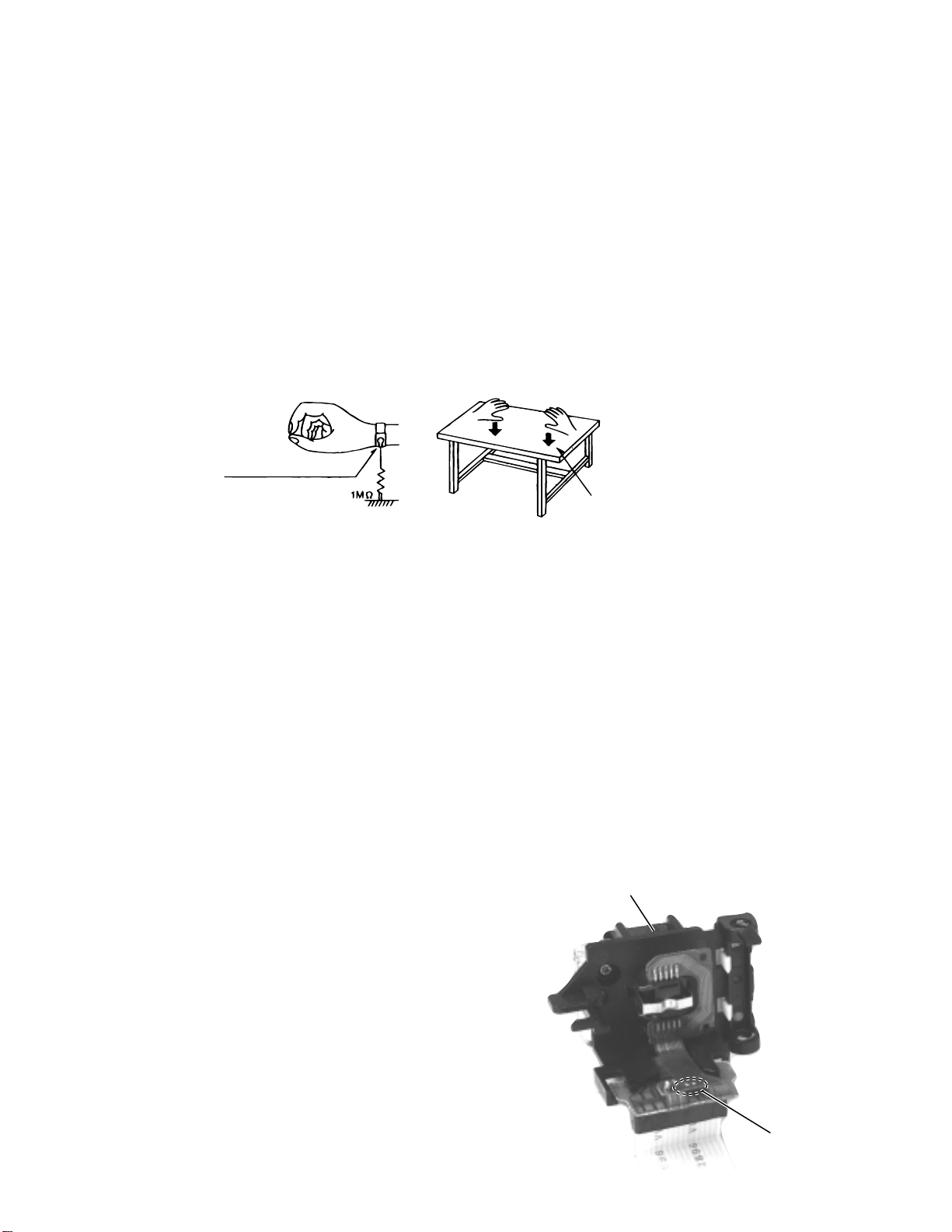
2-1 Ground the workbench
Ground the workbench by laying conductive material (such as a conductive sheet) or an iron plate over
it before placing the traverse unit (optical pickup) on it.
2-2 Ground yourself
Use an anti-static wrist strap to release any static electricity built up in your body.
(caption)
Anti-static wrist strap
Conductive material
(conductive sheet) or iron plate
3. Handling the optical pickup
1. In order to maintain quality during transport and before installation, both sides of the laser diode on the
replacement optical pickup are shorted. After replacement, return the shorted parts to their original condition.
(Refer to the text.)
2. Do not use a tester to check the condition of the laser diode in the optical pickup. The tester's internal power
source can easily destroy the laser diode.
4.Handling the traverse unit (optical pickup)
1. Do not subject the traverse unit (optical pickup) to strong shocks, as it is a sensitive, complex unit.
2. Remove solder of the land on the flexible cable after replacing the optical pickup. For specific
details, refer to the replacement procedure in the text. Remove the anti-static pin when replacing the traverse
unit. Be careful not to take too long a time when attaching it to the connector.
3. Handle the flexible cable carefully as it may break when subjected to strong force.
4. It is not possible to adjust the semi-fixed resistor that adjusts the laser power. Do not turn it
CD Pick up
Attention when traverse unit is decomposed
*Please refer to "Disassembly method" in the text for pick-up and
how to detach the substrate.
1.Short the land before the card wire is removed from connector on
the Main board as shown in Figure.
(When the wire is removed without putting up solder, the CD pick-up
assembly might destroy.)
2.Please remove solder after connecting the card wire with
when you install picking up in the substrate.
1-4
Land
Page 5
Important for laser products
RC-BZ5LB/BZ5RD
RC-BZ6BU
1.CLASS 1 LASER PRODUCT
2.DANGER : Invisible laser radiation when open and inter
lock failed or defeated. Avoid direct exposure to beam.
3.CAUTION : There are no serviceable parts inside the
Laser Unit. Do not disassemble the Laser Unit. Replace
the complete Laser Unit if it malfunctions.
4.CAUTION : The compact disc player uses invisible
laserradiation and is equipped with safety switches
whichprevent emission of radiation when the drawer is
open and the safety interlocks have failed or are de
feated. It is dangerous to defeat the safety switches.
5.CAUTION : If safety switches malfunction, the laser is able
to function.
6.CAUTION : Use of controls, adjustments or performance of
procedures other than those specified herein may result in
hazardous radiation exposure.
CAUTION
!
Please use enough caution not to
see the beam directly or touch it
in case of an adjustment or operation
check.
REPRODUCTION AND POSITION OF LABELS
WARNING LABEL
CLASS 1
LASER PRODUCT
1-5
Page 6
RC-BZ5LB/BZ5RD
RC-BZ6BU
Disassembly method
<Main body>
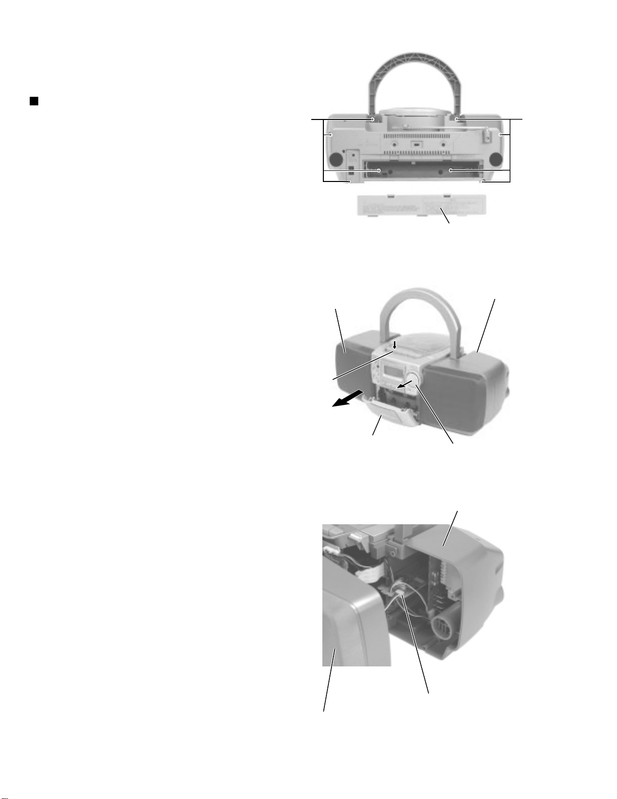
Removing the front cabinet assembly /
rear cabinet assembly (See Fig.1 to 3)
1.
Detach the battery cover on the back of the body.
Remove the eight screws A attaching the front
cabinet assembly and the rear cabinet assembly.
2.
Press STOP / EJECT button on the upper side of the
body to open the cassette door.
3.
Remove the front cabinet assembly toward the front
and pull out the volume knob at the same time.
4.
Disconnect the speaker harness from connector
CN309 on the main board in the rear cabinet
assembly.
A
Front cabinet assembly
A
Battery cover
Fig.1
Rear cabinet assembly
STOP / EJECT button
assembly /
Cassette door
Volume knob
Fig.2
Rear cabinet assembly
1-6
Main board
CN309
Front cabinet assembly
Fig.3
Page 7
<Front cabinet assembly>
RC-BZ5LB/BZ5RD
RC-BZ6BU
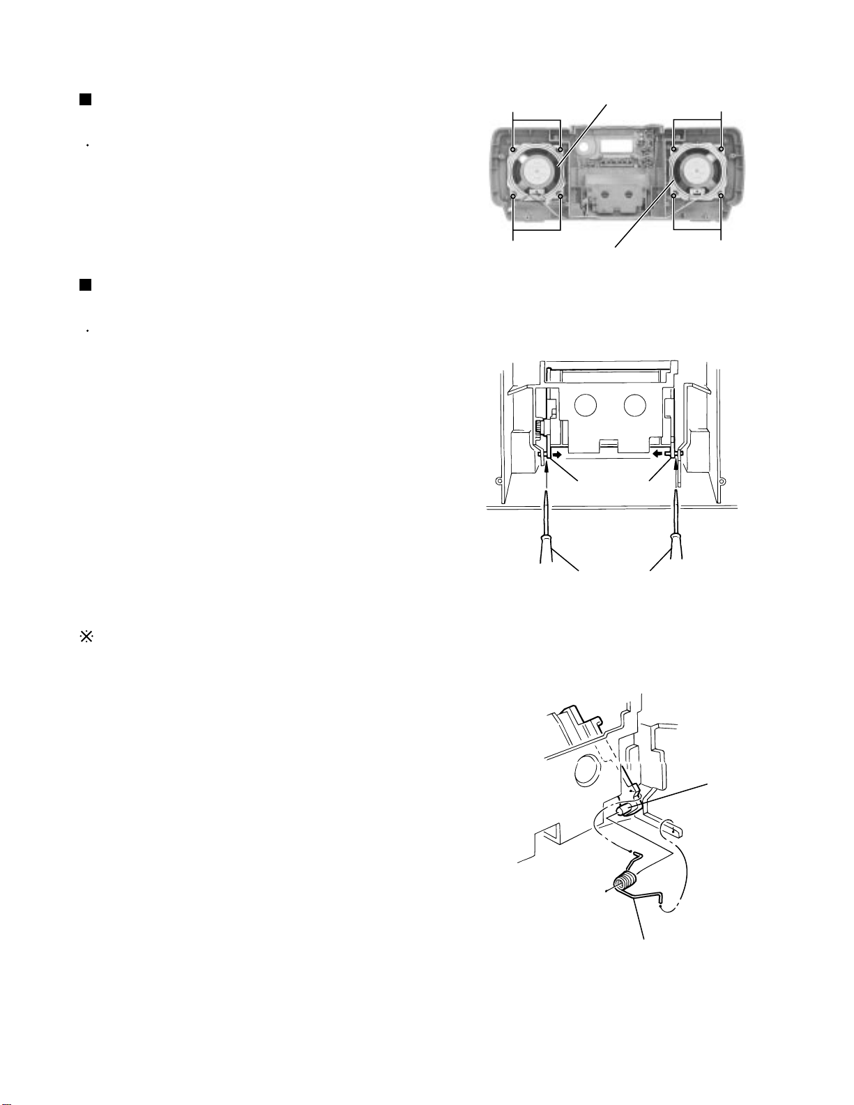
Removing the speaker (L) and (R)
(See Fig.4)
Prior to performing the following procedure, remove
the front cabinet assembly.
1.
Remove the eight screws B in the front cabinet.
Removing the cassette door
(See Fig.5 and 6)
Prior to performing the following procedure, remove
the front cabinet assembly.
1.
Remove the door spring in the front cabinet
assembly.
2.
Insert a screwdriver between the door arm and the
front cabinet and slide the door arms inward, then
detach the cassette door from the front cabinet.
B
B
Speaker (L)
Speaker (R)
Fig.4
Door arms
B
B
Reattaching the door spring
1.
Reattach the door spring to the cassette door shaft
with opening the cassette door.
2.
Fit another end of the door spring to the front cabinet
rib.
3.
Fit the shorter end of the door spring to the cassette
door.
Screwdriver
Fig.5
Shaft
Door spring
Fig.6
1-7
Page 8
RC-BZ5LB/BZ5RD
RC-BZ6BU
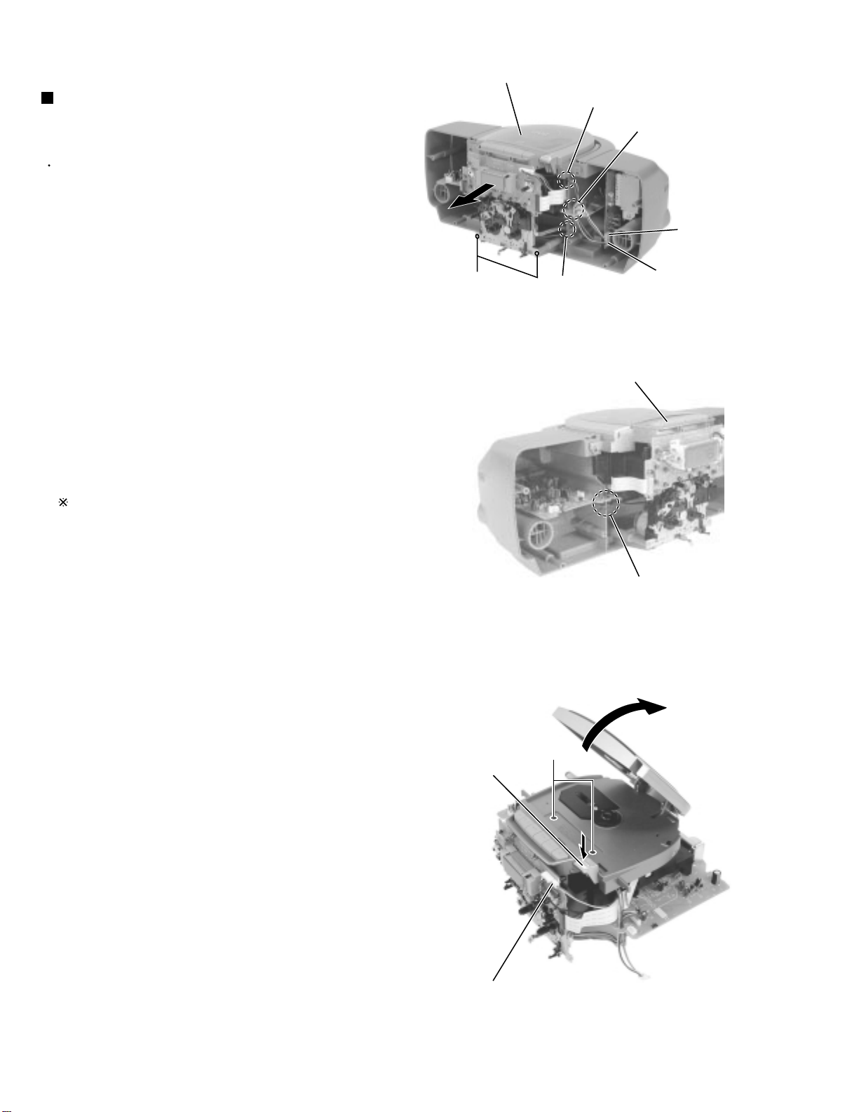
<Rear cabinet assembly>
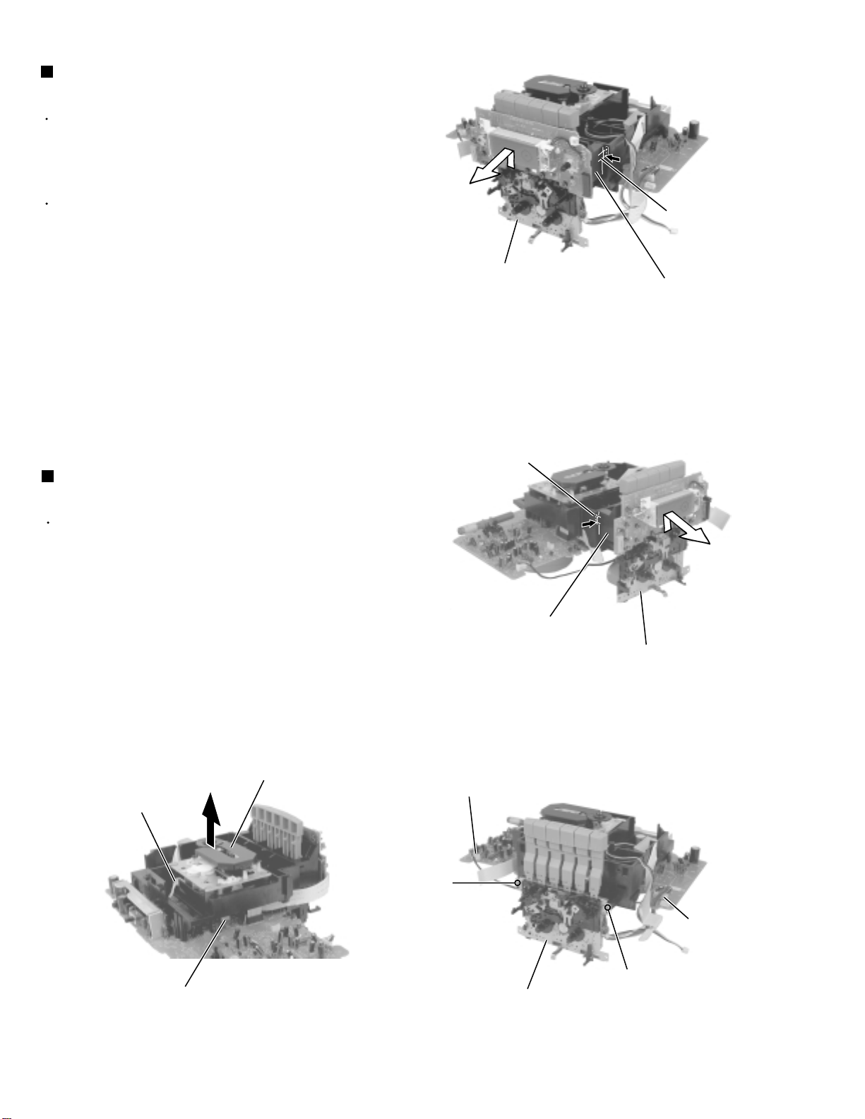
Removing the CD / cassette and amplifier
assembly from the rear cabinet
(See Fig.7 and 8)
Prior to performing the following procedure, remove
the front cabinet assembly and the rear cabinet
assembly.
1.
For the harness connecting the amplifier board with
the power board, disconnect it from connector
CN306 on the power board in the right rear cabinet
assembly. For the harness connecting the battery
terminal wire with the power board, disconnect it
from CN307 on the power board.
2.
Remove the two screws C on the bottom of the
cassette mechanism unit.
3.
Release the harnesses from the slot a, b and c and
the notch of the main board in the rear cabinet.
4.
Remove the CD / cassette and amplifier assembly
from the rear cabinet.
CD / cassette and amplifier assembly
Slot a
Release the hornese
C
CD / cassette and amplifier assembly
Slot c
Fig.7
Power board
CN307
CN306
Now the CD / cassette and amplifier assembly is
ready to conduct burn-in.
Slot b
Fig.8
D
CD door eject button
1-8
Key switch / display board
CN704
Fig.9
Page 9

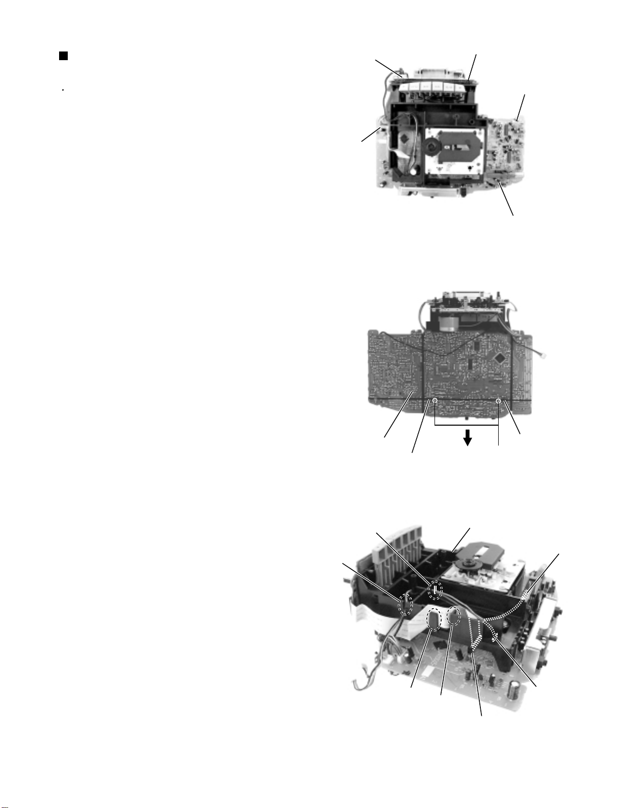
Removing the CD cover and door unit
(See Fig.9 and 10)
Prior to performing the following procedure, remove
the CD / cassette and amplifier assembly.
1.
Disconnect the harness from connector CN704 on
the key switch / display board (The harness is
extending from the door switch board).
2.
Press EJECT button to open the CD door.
3.
Remove the two screws D on the front of the CD
cover and door unit.
4.
Raise the front part of the CD cover and door unit
and detach upward. Then push the whole unit
backward until it comes off.
RC-BZ5LB/BZ5RD
RC-BZ6BU
CD cover and door unit
Fig.10
ATTENTION:
At this point, the CD mechanism unit
will become removable. So handle the
rear cabinet with care.
Removing the CD door switch board
(See Fig.11)
Prior to performing the following procedure, remove
the CD cover and door unit.
1.
Turn over the CD cover and door unit and gently
spread apart the locking tab. Then remove the CD
door switch board in the direction of the arrow while
releasing it from joint d.
Removing the key switch / display board
(See Fig.12)
Prior to performing the following procedure, remove
the front cabinet assembly and the rear cabinet
assembly.
Tab
Joint d
CD door switch board
Fig.11
Key switch / display boardKey switch / display board
CN702(RC-BZ5 only)
CN704
1.
Disconnect the card wires from connector CN701,
CN702 and CN703, then the harness from CN704
on the key switch / display board.
2.
Remove the four screws E attaching the key switch /
display board.
The key switch / display board can be removed
even if the mechanism cover is attached.
CN703
E
Cassette mechanism assembly
Fig.12
E
CN701
1-9
Page 10
RC-BZ5LB/BZ5RD
RC-BZ6BU
Removing the cassette mechanism
assembly (See Fig.13 to 15)
Prior to performing the following procedure, remove
the CD / cassette and amplifier assembly, the CD
cover and door unit and disconnect the harnesses
connected to the key switch / display board.
The cassette mechanism cover is still attached.
1.
Push inward the locking tabs e on both sides of the
cassette mechanism cover and remove the
mechanism cover in the direction of the arrow.
2.
Disconnect the harnesses from connector CN301
and CN308 on the main board.
3.
Remove the upper two screws F and the cassette
mechanism assembly toward the front.
Removing the CD mechanism assembly
(See Fig.16)
Prior to performing the following procedure, remove
the CD / cassette and amplifier assembly, the CD
cover and door unit.
1.
Disconnect the harness from connector P011 on the
motor board in the lower part of the CD mechanism
assembly. Then disconnect the pickup card wire
from CN601 on the main board.
2.
Remove the CD mechanism assembly upward.
Cassette mechanism assembly
Fig.13
Locking tab e
Cassette mechanism cover
Fig.14
Locking tab e
Cassette mechanism
Cassette mechanism assembly
cover
1-10
Motor board
P011
Main board
CN601
CD mechanism assembly
CN301
F
Cassette mechanism assembly
Fig.15Fig.16
Main board
CN308
F
Page 11
RC-BZ5LB/BZ5RD
RC-BZ6BU
Removing the main board
(See Fig.17 to 19)
Prior to performing the following procedure, remove
the CD / cassette and amplifier assembly, the CD
cover and door unit and the CD mechanism
assembly.
1.
Disconnect the harnesses from connector CN301
and CN308 on the main board (The harnesses are
extending from the cassette mechanism assembly).
2.
Disconnect the harness from connector CN702 on
the key switch/display board (RC-BZ5 only).
3.
Remove the two screws G on the underside of the
main board and release the two joint tabs f from the
chassis in the direction of the arrow.
ATTENTION:
When reassembling, get the harness
extending from FW301 and FW302
on the m a i n board through the two
slots g of the chassis. Get the card
wire extending from CN304 on the
main board through the hook h
and the slot i.
CN308
CN702
Key switch/display bord
CN301
Main board
Fig.17
g
Main board
Joint tab f
g
Joint tab f
G
Fig.18
Chassis
FW302(RC-BZ5 only)
h
i
CN304
FW301
Fig.19
1-11
Page 12
RC-BZ5LB/BZ5RD
RC-BZ6BU
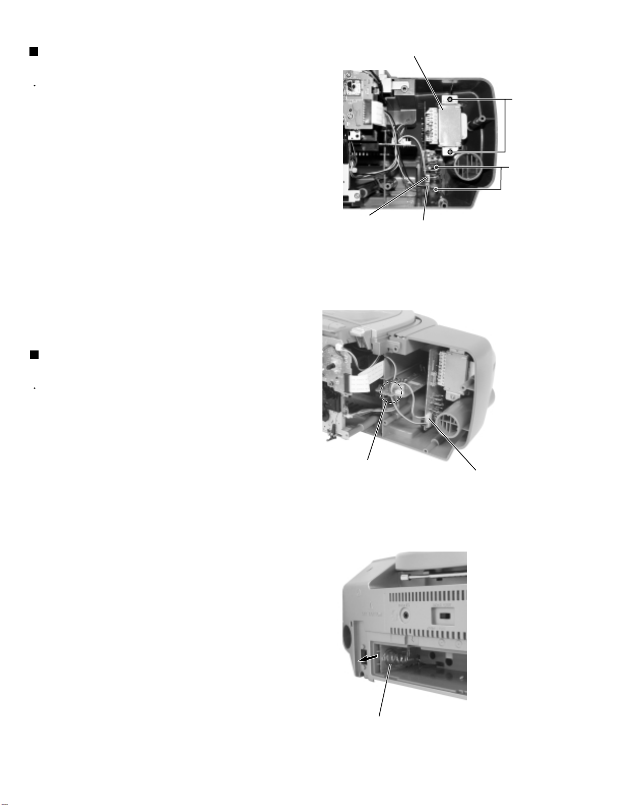
Removing the power transformer
assembly (See Fig.20)
Prior to performing the following procedure, remove
the front cabinet assembly and the rear cabinet
assembly.
1.
Disconnect the harnesses from connector CN306
and CN307 on the power board in the power
transformer assembly.
2.
Remove the two screws H attaching the AC jack of
the power board and the two screws I attaching the
power transformer.
Remove the power transformer assembly toward the
front.
Power transformer assembly
Power board
CN307
I
H
CN306
Fig.20
Removing the battery board
(See Fig.21 and 22)
Prior to performing the following procedure, remove
the front cabinet assembly and the rear cabinet
assembly.
1.
Disconnect the battery terminal wire from connector
CN307 on the power board.
2.
Remove the battery board on the back of the rear
cabinet.
Release the hornese
Power board
CN307
Fig.21
1-12
Battery board
Fig.22
Page 13
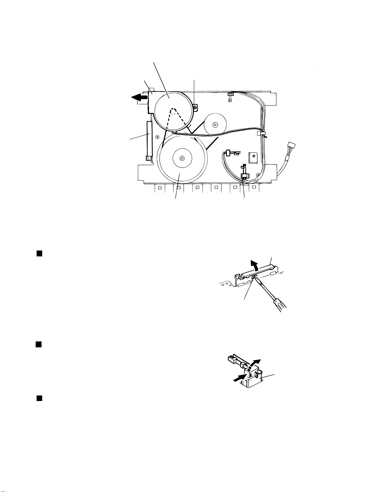
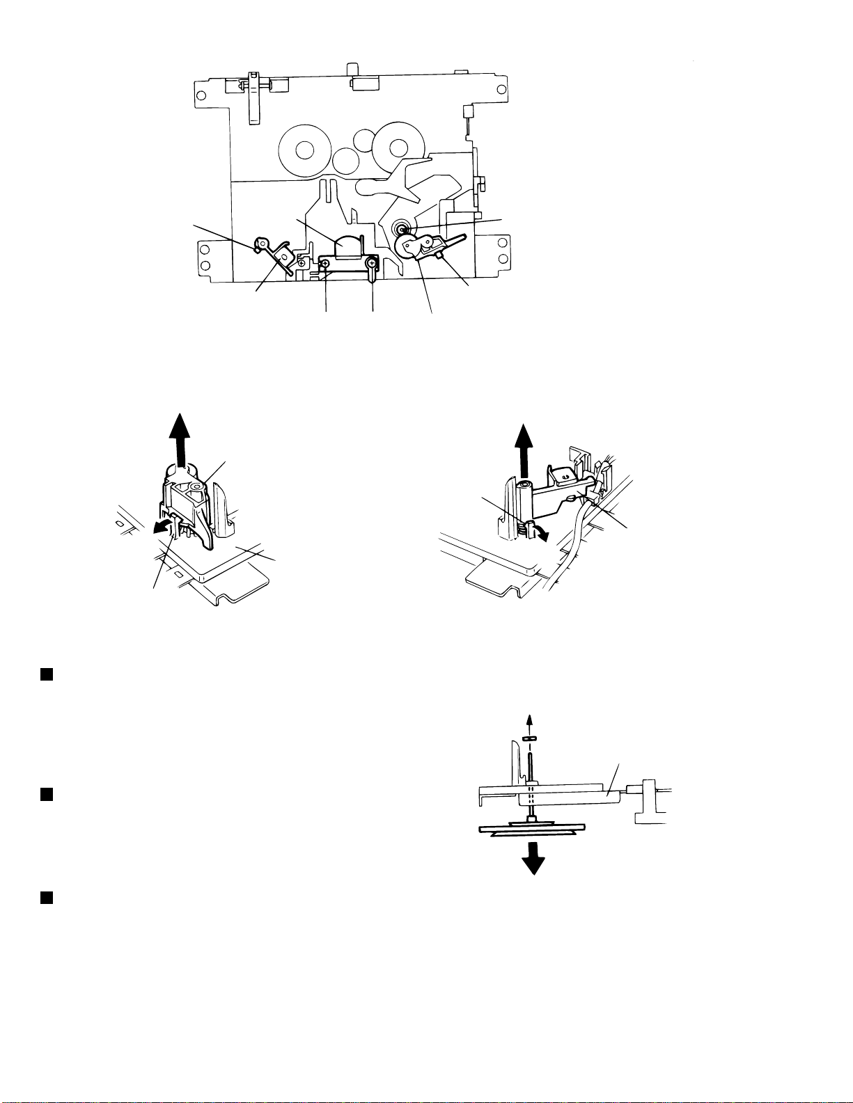
<Cassette mechanism section>
Capstan motor ass’ y
RC-BZ5LB/BZ5RD
RC-BZ6BU
Motor bracket
a
Eject slide
lever
Flywheel ass’ y Leaf switch
Fig.1
Capstan motor
1. Remove the cassette mechanism assembly. (Refer
to the article “Cassette mechanism assembly”
appearing on a previous page.)
2. Remove one screw A retaining the capstan motor
assembly from the back of the cassette mechanism
assembly.
3. Disengage the main belt from the flywheel assembly.
Then slide the capstan motor slightly in the direction
of the arrow a while lifting it upwards to remove
together with the main belt.
(Fig.1)
A
Main belt
b
Stopper arm
Fig.2
Eject slide lever
Eject slide lever
1. Place the cassette mechanism back side frontward
and disengage the stopper arm b of the Eject slide
lever by pressing it inwards through the opening of
the chassis with a small screwdriver as shown in
Fig.2.
Leaf switch
1. Press the leaf switch in the direction of the arrow c
and then remove it in the direction of the arrow d
referring to Fig.3.
(Fig.2)
(Fig.3)
d
Leaf switch
c
Fig.3
1-13
Page 14
RC-BZ5LB/BZ5RD
RC-BZ6BU
Stopper
Rec/PB
head
Capstan shaft
Erase head
B
C
Fig.4
f
Pinch roller arm ass’y
e
Base ass’y
Stopper
Fig.5 Fig.6
Pinch roller arm assembly
1. Pull out the stopper protruding from the base assembly
in the direction of the arrow e to remove it from the
pinch roller arm assembly.
2. Then, pull out the pinch roller arm assembly in the
direction of the arrow f.
(Fig.4 to 5)
Stopper
Pinch roller arm ass’y
h
Stopper
Erase head
g
i
P washer
Base ass’y
Rec/PB head and erase head
1. Remove two screws B, C retaining the Rec/PB head.
2. Pull out the stopper of the erase head in the direction of
the arrow g.
3. Pull out the erase head in the direction of the arrow h.
Flywheel assembly
1. Remove the split washer retaining the flywheel
assembly in the direction of the arrow i.
2. Pull the flywheel assembly out of the back side of the
cassette mechanism assembly in the direction of the
arrow j.
1-14
(Fig.7)
(Fig.4 to 6)
Flywheel
j
Fig.7
Page 15

Adjustment method
RC-BZ5LB/BZ5RD
RC-BZ6BU
Test Instruments required for adjustment
1. Low frequency oscillator
(Frequency range: 50Hz to 20kHz)
(Output: 0 dBs across 600 Ω terminating resistor)
2. Attenuator(Impedance: 600 Ω)
3. T est Tapes
VT712 For tape speed, wow & flutter check
VT722, 724 For playback, output level check
VT738 For playback frequency response check
VT702 For head azimuth adjustment
4. Blank tape TYPE1:AC–225
5. Electronic voltmeter
6. Distortion meter
7. Frequency counter
8. Wow and flutter meter
9. Torque gauge(Cassette type) CTG – N
10. Test disc CTS1000
11. Jitter meter NJM631
12. TE Offset LTM9055
Measuring conditions(Amplifier section)
Supply voltage AC120V(60Hz)
DC12V(UM–1 x 8)
Reference output level Speaker
: 0 dBs(0.775V) / 3 Ω
Headphone
: –10 dBs(0.245V) / 32 Ω
Reference input level
: –20 dBs supplied to test point CN1
Standard test frequency 1kHz
Output measuring point Speaker terminal
:Dummy load 3 Ω
Standard position of switches
Function switch TAPE
Beat cut switch NORMAL
Standard position of controls
Tone Maximum position
Main volume adjust 0 dBs output position
Test remarks
1. Negative side of the input and output terminals of the
testing set, shall be isolated from each other. The
negative side should not be commonly connected
when a 2channel electronic voltmeter is connected.
2. A dummy load shall be connected to the output
terminal and the lead wires of dummy load shall be
as thick as possible.
Measuring condition(Tuner section)
Power supply voltage to tuner Vcc: DC 6V
Reference output Speaker: 0.245V/3 Ω
AM modulation 400Hz, 30%
FM modulation 400Hz, deviation 22.5kHz
Remarks for alignment
1. Connect 30 pF capacitor and 33k Ω resistor to the
output terminal of the IF sweeper in series while
0.082 µ F capacitor and 100k Ω resistor to the input
terminal in series.
2. Set the output level of the IF sweeper as low as
adjustable.
3. IF alignment is not necessary for both AM and FM
MPX alignment is not necessary either. All IFTs and
MPX coil are non-adjusting type.
1-15
Page 16

RC-BZ5LB/BZ5RD
RC-BZ6BU
Cassette amplifier section
Item
Head azimuth
adjustment
Tape speed,
Wow & flutter
check
Conditions Adjustment & Confirmation Method Standard Value Adjusting Point
• Test tape:
VT702(8 kHz)
• Test output from:
Speaker terminal
(with 3 Ω load)
• Function selector:
TAPE
• Test tape:
VT712 (3 kHz)
•Test output from:
Speaker terminal
(with 3 Ω load)
1. Play back the test tape VT702 (8 kHz signal).
2. Adjust the azimuth adjusting screw so that
phase difference between R and L channels is minimum with the output level that
is the maximum level plug less than 2 dB
in the FWD and REV mode.
After the adjustment apply screw sealant
onto the azimuth adjusting screw for more
than half the screw head.
3. If the head azimuth is still maladjusted, readjust it with the azimuth adjusting screw
alternately in the FWD and REV modes.
1. Play back the end portion of the test tape
VT712 (3 kHz signal).
2. At that time check to see if the frequency
counter reads 2940 to 3090 Hz. If not,
adjust the semi-fixed resistor inside the
motor to obtain the specified frequency.
3. Wow and flutter must be 0.38 % or less
(unweighted).
• Output: Max.
level plus less
than 2 dB
• Phase difference between
R & L ch:
Minimum
Frequency:
2940-3090 Hz
0.38 % or less
(unweighted)
Azimuth adjusting
screw (after head
replacement only)
Tape speed (with
semi-fixed resistor
inside motor)
Playback
output check
Playback
frequency
response
check
REC/PB
sensitivity
check
• Function selector:
TAPE
• Test tape: VT722,
VT724 (1 kHz)
• Test output from:
Speaker terminal
(with 3 Ω load)
• Function selector:
TAPE
• Test tape: VT738
• Test output from:
Speaker terminal
(with 3 Ω load)
• Function selector:
TAPE
• Mode: Recording
• Test input to:
CN301
1. With the test tape VT722 (1 kHz signal)
being played back, confirm that the speaker
output is 2.1 W or more with 10 % distortion.
2. With the test tape VT724 being played
back, confirm that the deviation between
R-ch and L-ch outputs is less than 3 dB.
With the test tape VT738 being played back,
confirm that the deviation between 1 kHz and
125 Hz signals is 6 ± 3 dB and that between
the 1 kHz and 8 kHz signals is 0 ± 4 dB.
With the input of 1 kHz, –20 dBs signal to the
test point CN301, confirm that the level difference between the recording and playback
is 0 ± 3 dB or less.
• Speaker output
with 10 %
distortion:
2.1W or more
• Deviation between R & L ch
outputs:
3 dB or less
• Deviation
between 1 kHz
& 125 Hz:
6 ± 3 dB
• Deviation
between 1 kHz
& 8 kHz:
0 ± 4 dB
• Level difference
between
REC & PB:
0 ± 3 dB or less
1-16
Page 17
RC-BZ5LB/BZ5RD
Tuner sections
Item Conditions Adjustment & Confirmation Methods Stand. values Adjust
RC-BZ6BU
FM, AM IF
adjustment
MPX
adjustment
FM tracking
adjustment
Since a solid IF is being used, no
adjustment is required.
Since a ceramic resonator is being used,
no adjustment is required.
Since a fixed coil is being used, no
adjustment is required.
1-17
Page 18
RC-BZ5LB/BZ5RD
RC-BZ6BU
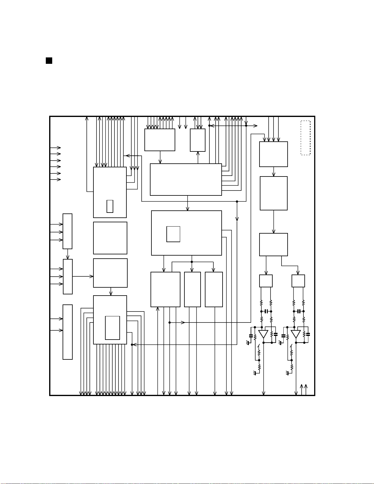
Description of major IC's
MN35510 (IC603) : Digtal servo & digtal signal processor
1. Block diagram
BYTCK
SMCK
PMCK
VDD
VSS
DVDD1
VDSS1
/RST
/TEST
MSEL
STAT
X2
X1
CSEL
PITCH CONTROL
FCLK
GENERATOR
VCOF
TIMING
CK384(EFM)
MDATA
MCLK
MLD
PSEL
RSEL
ARF
DRF
DSLF
PLLF
IREF
PLL VCO
DSL
DEMODULATION
AVDD2
EFM
PCK
SUBCODE
AVSS2
INTERPOLATION
SYNC
SQCK
SUBQ
SUBCODE
BUFFER
DEMODULATION
SSEL
EFM
FLAG5(RESY)
DEMPH
RESY
SUBC
SBCK
/CLDCK
BLKCK
CRC
SRDATAIN(PSEL)
LRCKIN(MSEL)
BCLKIN(SSEL)
IOSEL
CLVS
MN35510
DEEMPHSIS
DIGITAL
8TIMES
OVER SAMPPUNG
DIGITAL FILTER
RFENV
TRCRS
VDET
BDO
/RFDET
OFT
VCO
A/D CONVERTER
FE
TE
INPUT PORT
SERVO
TIMING GENERATOR
MICRO COMPUTER
INTERFACE
SERVO
CPU
OUTPUT
PORT
D/A
CONVERTER
ATTENUATION
PEAK DETCT
AUTO CUE
SRAM
SOFT MUTING
DIGITAL
15K
INTER POLATION
DEINTERLEVE
CORRECTION
CIRC ERROR
SERVO
CLV
1BIT DAC
LOGIS
PWM
INTERFACE
DIGITAL
AUDIO
(L)
–
+
PWM
(R)
–
+
1-18
SENSE
WVEL
LDON
PLAY
TES
/TLOCK
/FLOCLK
TOFS
FBAL
TBAL
FOD
TRD
TVD
ECS
(BYTCK)TRVSTR
VREF
KICK
TRV
DMUTE
BCLK
SRDATA
LRCK
PC
ECM
TX
FLAG
IPFLAG
OUTL
OUTR
AVDD1
AVSS1
Page 19

BA6897FP (IC602) : 4channel driver
1.Terminal layout & Block diagram
RC-BZ5LB/BZ5RD
RC-BZ6BU
CH1-OUTA
CH1-OUTB
CH1-INA
CH1-INB
TEST1
TEST2
MUTE
CH2-INB
CH2-INA
CH2-OUTB
CH2-OUTA
GND
D.BUF
1
2
D.BUF
- +
D.BUF
D.BUF
Level
shift
+-
Level
shift
- +
-+
3
4
5
6
7
8
9
10
11
12
13
T.S.D
DRIVER
MUTE
+ Level
shift
+-
-+
Level
shift
+ -
-+
D.BUF
D.BUF
D.BUF
D.BUF
28
GND
CH4-OUTA
27
CH4-OUTB
26
CH4-INA
25
CH4-INB
24
BIAS IN
23
Vcc
22
Vcc
21
CH3-INB
20
19
CH3-INA
18
CH3-OUTB
17
CH3-OUTA
16
OP IN(+)
OP-OUT
14
-+
15
OP IN(-)
1-19
Page 20

RC-BZ5LB/BZ5RD
RC-BZ6BU
LC72136N (IC2) : PLL Frequency sinsesizer
1.Terminal layout
1
FM/AM
CLOCK
DO1
FM ST VCO STOP
AM/FM
SDIN
2. Block diagram
XT
CE
DI
NC
NC
2
3
4
5
6
7
8
9
10
11
22
21
20
19
18
17
16
15
14
13
12
XT
GND
LPFOUT
LPFIN
PD
VCC
FMIN
AMIN
NC
IFCONT
IFIN
1-20
1
22
16
15
3
4
5
6
17
21
3. Pin function
Pin
Symbol
No.
1
2
3
4
5
6
7
8
9
10
11
XT
FM/AM
CE
DI
CLOCK
DO1
FM ST
VCO STOP
AM/FM
NC
NC
SDIN
Reference
Driver
Swallow Counter
1/2
2
B
C
I/F
Power
on
Reset
Function
I/O
X'tal oscillator connect (75KHz)
I
LOW:FM mode (Not use)
O
When data output/input for 4pin(input) and
I
Swallow Counter
1/16,1/17 4bit
1/16,1/17 4bit
12bit
Programmable
DriverS
Data Shift Register & Latch
7821113
6pin(output): H
Input for receive the serial data from
I
controller
Sync signal input use
I
Data output for Controller
O
Output port
"Low": MW mode
O
O
Not use
Not use
Data input/output (Not use)
I/O
Phase
Detector
Charge Pump
Unlock
Detector
Universal
Counter
Pin
No.
12
13
14
15
16
17
18
19
20
21
22
Symbol
IFIN
IFCONT
NC
AMIN
FMIN
VCC
PD
LPFIN
LPFOUT
GND
XT
18
19
20
12
I/O
Function
IF counter signal input
I
IF signal output
O
Not use
-
AM Local OSC signal output
I
FM Local OSC signal input
I
Power supply(VDD=4.5 5.5V)
When power ON:Reset circuit move
PLL charge pump output(H: Local OSC
O
frequency Height than Reference frequency.
L: Low Agreement: Height impedance)
Input for active lowpassfilter of PLL
I
Output for active lowpassfilter of PLL
O
Connected to GND
X'tal oscillator(75KHz)
I
Page 21

TA2104AN (IC1) : AM/FM 1 chip tuner IC
1.Terminal layout & Block diagram
RC-BZ5LB/BZ5RD
RC-BZ6BU
FM
RF OUTRFVcc
GNDFMRF INAMLOW CUT
2.Pin function
FMRF
AM
RF IN
222324
AM
MIX
FM
OSC
21
FM
OSC
FM
MIX
4 6 9
MIX
OUT
AM
OSC
20
AM
OSC
BUFF
BUFF
521 3 7 8
Vcc
OSC
OUT
19 18 17 16
LEVEL
DET
AMIF FMIF
IF INFMIF IN
ST
LED
SW
ST
IF
BUFF
1 / 8
IF
REQ
IF
REQ
AM
DET
GNDRF
AF
BUFF
AGC
DET
OUT
AGC QUAD R-OUT L-OUTAM
FM
DET
MPX
IN LPF1 LPF2
15
AF
10 11 12
14 13
VCO
DIVIDE
ST / MO
FM / AM
DECODE
MUTE
Pin
Pin Name
1
RF GND
2
FM RF IN
3
AM LOW CUT
4
MIX OUT
5
Vcc
6
AM IF IN
7
FM IF IN
8
GND
9
AGC
QUAD
10
R-OUT
11
L-OUT
12
LPF2
13
LPF1
14
MPX IN
15
DET OUT
16
IF REQ
17
ST LED
18
OSC OUT
19
AM OSC
20
FM OSC
21
AM RF IN
22
RF Vcc
23
FM RF OUT
24
Function
RF Stage ground
FM RF Input
AM Low Frequency Cut Filter External Component
Mixer Output
Power Supply
AM IF Amplifier Input
FM IF Amplifier Input
Ground
AM AGC External Capacitor
FM Quadrature Detector Terminal
Audio output CH-R
Audio output CH-L
LPF Terminal for Phase Detector / AM, FM Switching
LPF Terminal for Synchronous Detector / VCO Stop
FM MPX Input
AM/FM Detector Output
IF Output / IF Request control
FM Stereo Indicator Output
Local Oscillator Output
AM Oscillator
FM Oscillator
AM RF Input
RF Stage Vcc
FM RF Amplifier Output
1-21
Page 22

RC-BZ5LB/BZ5RD
RC-BZ6BU
AN8806SB (IC601) : RF & Servo amplifier
1.Treminal layout
PD
LD
LDON
LDP
VCC
RF-
RFOUT
RFIN
C.AGC
ARF
C.ENV
C.EA
CSBDO
BDO
CSBRT
OFTR
/NRFDET
GND
1
2
3
4
5
6
7
8
9
10
11
12
13
14
15
16
17
18
36
35
34
33
32
31
30
29
28
27
26
25
24
23
22
21
20
19
PDAC
PDBD
PDF
PDE
PDER
PDFR
TBAL
FBAL
FE FEOUT
TE TEOUT
CROSS
TEBPF
VDET
LDOFF
VREF
ENV
2.Block diagram
36
35
31
34
32
6
VCBA
29
728
VCBA
VCBA
VCBA
8
27
EQ
OFTR
910 17
AGC
RF
DET
BDO
11
12 19
ENV CIRCUIT
13
14
15
16
20
1-22
21
33
24 25
30
23
26
22
14
3
2
Page 23

3. Pin function
RC-BZ5LB/BZ5RD
RC-BZ6BU
Pin No.
1
2
3
4
5
6
7
8
9
10
11
12
13
14
15
16
17
18
19
20
21
22
23
24
25
26
27
28
29
30
31
32
33
34
35
36
Symbol
PD
LD
LDON
LDP
VCC
RF-
RFOUT
RFIN
C.AGC
ARF
C.ENV
C.EA
CSBDO
BDO
CSBRT
OFTR
/NRFDET
GND
ENV
VREF
LDOFF
VDET
TEBPF
CROSS
TEOUT
TE-
FEOUT
FEFBAL
TBAL
PDFR
PDER
PDE
PDF
PDBD
PDAC
I/O
I
APC amp input terminal
APC amp output terminal
O
APC ON/OFF control terminal
I
--
Connect to ground
Power supply
-Inverse input pin for RF amp
I
RFamp output
O
RF input
I
Connecting pin of AGC loop filter
I/O
RF output
O
I/O
A capacitor is connected to this terminal to detect the envelope of RF signal
I/O
A capacitor is connected to this terminal to detect the envelope of RF signal
A capacitor is connected to detect the lower envelope of RF signal
I/O
BDO output pin
O
A capacitor is connected to detect the lower envelope of RF signal
I/O
O
Of-track status signal output
RF detection signal output
O
--
Ground
O
Envelope output
Reference voltage output
O
Function
I
O
Vibration detection signal output
I
Input pin of tracking error through BPF
O
Tracking error cross output
O
Tracking error signal output
Inverse input pin for tracking error amp
I
O
Output pin of focus error
Inverse input pin for focus error amp
I
I
Focus balance control
I
Tracking balance control
F I-V amp gain control
I/O
E I-V amp gain control
I/O
I
I-V amp input
I-V amp input
I
I
I-V amp input
I I-V amp input
1-23
Page 24

RC-BZ5LB/BZ5RD
RC-BZ6BU
TA2068N (IC301) : Rec/PB. amplifier
1. Terminal layout
1
AGC
2
PBO1
REC1
VREF
VSS
REC2
PBO2
3
4
5
6
7
8
9
10
11
12
PBNF1
PBIN1
PBIN2
PBNF2
MICNF
2. Block diagram
24
23
22
21
20
19
18
17
16
15
14
13
RAIN1
MICSEL
CDIN1
P/R
OUT1
VCC
OUT2
SEL
CDIN2
TAPE
RAIN2
MICIN
22
24235
19
13
12
6
7
REF. AMP
RADIO
TAPE
NAB AMP1
–
46.5
+
MIC AMP1
–
19.5
+
NAB AMP2
+
2.1V
8 10 11 14 16 15 17
46.5
–
LINE
TAPE
BUF. AMP A1BUF. AMP A1
MUTE
ON
BUF. AMP A2
TAPE
LINE
TAPE
RADIO
+
–
BUF. AMP B1
+
–
BUF. AMP B2
MUTE
ALC1
DET
ALC2
MUTE
LOGIC
MONITOR AMP 1
7
ON
REC AMP1
26
REC AMP2
26
MONITOR AMP
ON
7
21
20
4
1
9
2
18
23
1-24
Page 25

RC-BZ5LB/BZ5RD
RC-BZ6BU
VICTOR COMPANY OF JAPAN, LIMITED
AUDIO & COMMUNICATION BUSINSS DIVISION
PERSONAL & MOBILE NETWORK B.U. 10-1,1Chome,Ohwatari-machi,Maebashi-city,371-8543,Japan
(No.20819)
Printed in Japan
200007(S)
Page 26

Block diagrams (RC-BZ5LB/BZ5RD)
RC-BZ5LB/BZ5RD
RC-BZ6BU
R/P HEAD
L3
AM
BPF
BP1
CN301
IC2
PLL
L1
L4
FM RF/IF/DET/MPX
AM RF/IF/DET
IC1
CF1
Q101
REC
PB
Bias
+B
T2
Tuner
L&R
IC301
R/P Amp.
Main Volume
FW302
RCH
LCH
Q112
Q212
CN702
Q101
Q201
Q302
SMUTE
EQ
Power Amp.
LCH
RCH
RCH
LCH
CN309
IC302
J301
R-CH / L-CH
SPEAKER
CD Pickup
F/T
Coil
SPINDLE / FEED
MOTOR
M
M
CN601
RF/Servo amp.
IC601
Forcus
Spindle
Tracking
IC602
BTL Driver
Feed
IC603
Digital servo
Digital signal
Processor
SMUTE
CN303
CN703
IC701
SYSTEM
CONT.
2-1
Page 27

RC-BZ5LB/BZ5RD
RC-BZ6BU
Block diagrams (RC-BZ6BU)
L4
L3
AM
L.OSC
FM RF/IF/DET/MPX
AM RF/IF/DET
+B
R/P HEAD
CD Pickup
BPF
BP1
CN301
CN601
IC2
PLL
L1
REC
PB
Bias
RF/Servo amp.
IC1
CF1
Q101
T2
Tuner
L&R
IC301
R/P Amp.
Bass
Boost
Amp.
IC304
E.VOL
IC303
RCH
LCH
Q101
Q201
Q302
SMUTE
Power Amp.
LCH
RCH
RCH
IC302
LCH
CN309
J301
R-CH / L-CH
SPEAKER
F/T
Coil
SPINDLE / FEED
MOTOR
M
M
IC601
Spindle
Forcus
BTL Driver
IC602
Tracking
Feed
IC603
Digital servo
Digital signal
Processor
SMUTE
CN303
CN703
IC701
SYSTEM
CONT.
2-2
Page 28

Standard schematic diagrams
System control circuit (RC-BZ5LB/BZ5RD only)
TO MAIN AMP SECTION
TO D-1 on page 2-7
RC-BZ5LB/BZ5RD
RC-BZ6BU
CN701
7
SW8V
CD+B
FCD
AC/DC
TAPE
REC
SAFETY
REST
MLD
MDATA
MCLK
DG
XRST
STAT
SQCK
TO MAIN AMP SECTION
TO A-1 on page 2-7
SUBQ
DG
6
5
CD DOOR SW
S866
VMW14774 D
4
FW701
2
2
1
1
P8-22F23-A3.3NS
3
2
1
QGF1212F1-17
17
8.3V
16
6.8V
15
0.7V
14
2.1V
13
5.7V
12
0V
11
5.0V
10
4.6V
9
R774
5.1V
8
R775
4.8V
7
R776
5.0V
6
0V
5
R777
6.1V
4
R778
0.1V
3
R772
5.1V
2
R779
5.0V
1
0V
CN704
EMV5133-002KR OR TIP-X02P-MI
2
1
CN703
QGF1212F1-12
1K
1K
1K
1K
1K
1K
1K
SW8V
CD+B
D706
SAFETY
FCD
MLD
XRST
TAPE
REC
AC/DC
1SS133-T2
TUST
22K
0V
R709
5.1V
0V
5.1V 5.1V
R796 100K
BASS
POUT
SMUTE
FTU
TRE
C725
100P
Q704
DTC144EKA-X
+
C711
10/16
BCTL
4.4V
Q705
R738 10K
R735 10K
R746
R767
R768
R741
R739 22K
R758 2.2K
R761
C722
100P
AC/DC
R719 100K
RESET
Q706
0V
1SS133-TE
R706 10K
D707
2SA1037AK/RS/-X
22K
4.7K
10K
10K
2.2K
R708 10K
5.0V
DTC143TKA-X
0V
0V
5.0V
0V
0V
0V
0V
5.0V
6.0V
+
0V
0V
2.2K
R721
2.2/50
C712
43
44
45
46
47
48
49
50
51
52
53
54
55
56
57
58
59
60
61
62
63
R707
L701
3AB39N
SDATA
TUST
SCK
MPX
POUT
BASS
FTU
TPEDGBUC
SMUTE
US6V
123456789
0.9V0V0V0V1.1V0V0V0V0V
42
NC
NC
NC
NC
NC
NC
NC
NC
NC
BASS
POUT
SMUTE
+BCTL
FTU
NC
NC
TPE
FCD
MLD
XRST
BEAT
AC/DC64TAPE65STAT66REC67RESET68NC69NC70VSS71OSC272OSC173VDD74TUST75SQCK76SUBQ77MCLK78MDATA79SCK80SI81SO82PIN83PEN
5.1V0V0V0V5.4V0V5.4V0V2.0V
10K
R729
47K
10K
K701
VQZ0048-009
R740
K703
2.2K
R762
STAT
101112
5.1V
3.1V
VQZ0048-009
10K
R723
C710 0.01
220/10
+
C708
5.9V
33
34
35
36
2.6V
2.6V
2.6V
NC37NC38NC39NC40NC41NC
SEG16
SEG15
SEG14
SEG13
IC701
MN171603JACA
SYSTEM
CONTROLLER
2.4V
2.2K
R742
0.1
2SC2714/O/-X
R701
C707
30
31
32
2.6V
2.6V
2.6V
SEG11
SEG12
5.4V0V0V0V0V0V0V
R752 10K
C702
24P
Q701
1K
0V
2.2K
R753
0V
0V
2.6V
SEG10
29
R763 2.2K
2.6V
SEG9
28
R760 1K
8.2K
R702
SEG8
2.5V
27
1K
R759
C703 36P
25
26
2.5V
2.6V
SEG5
SEG6
SEG7
R751 10K
X701
QAX0410-001Z
CLOCK
23
24
2.6V
2.6V
SEG4
AVDD VREF+
CLOSE/REST
CD+B SAFETY
SW5V SAFETY
AVSS VREF-
0V0V5.4V
5.4V
R730 10K
R750 10K
C704 36P
2.6V
MODEL
8.2K
R703
SEG222SEG3
SEG1
SEG0
COM0
COM1
COM2
COM3
VLCD3
VLCD2
VLCD1
KEY1
BUP
MPX
VER
84
NC
NC
DI701
QLD0046-001
2.6V
21
2.6V
20
2.5V
19
18
17
2.5V
16
15
14
13
12
11
10
9
8
7
5.1V
6
5
3.7V
3.5V
4
3
2
1
C703
24P
2SC2714/O/-X
0V
0V
0V
2.5V
2.5V
0V
1.7V
3.3V
5.1V
4.6V
5.0V
0V
0V
0V
0V
0V
0V
C719
C720
0.001
0.001
C724
C723
C738
R748 22K
R749 47K
Q702
R704
1K
COM31COM22COM13COM0
R734
100K
R726
R725
R728 10K
R754 10K
R724 2.2K
R727
R785
R789
*
100P
100P
150P
C706
0.001
4
SEG05SEG16SEG27SEG38SEG49SEG510SEG611SEG712SEG813SEG9
REC BASS
TRACK
STEREO MONO
R733
R732
100K
100K
2.2K
2.2K
C732
0.1
2.2K
*
R773
10K
REST
MDATA
MCLK
SUBQ
SQCK
VQZ0048-009
R756 22K
SDATA
SCK
MPX
0.01
C721
R770
K702
L702
3AB39N
2.2K
14
SEG1015SEG1116SEG1617SEG1218SEG1319SEG1420SEG15
ALLSLEEP
KHz MHz
D702
1SS133-T2
R711 22K
39K
R714
R720 100K
+
C727 47/10
LIST
EE.EV
E.B.EN
U.UP.US.UT.UX.UY.UZ
J.C
PARTS NAME CONSTRUCTION
DTC143TKA
R718
10K
4.7K
R797
R712 10K
5.0V
3
5.0V
2
0V
1
R789 R785
10K
10K
10K
4.7K
LCD HOLDER
D703
UZ5.16SC-T2
47K
R716
0.6V
0V
R710
R715
OUT
VCC
GND
REMOCON
NOTES:
150K
22K
8.2K
2.2K-------
21
REPEAT
S858
R857
39K
R856
12K
R855
6.8K
R854
3.9K
R853
2.7K
R852
1.8K
R851
1.5K
R717 33K
BACK UP
Q703
2SC2412K/R/-X
0V
UP/
S857
CD/
S856
STOP/
S855
TUNER/BAND
S854
DOWN/
S853
PRESET
S852
SOUND
S851
S851---S858
QSW0707-001Z
QSW0707-001Z
POWER
S865
100K
33K
IC703
GP1U281X
VMW2422 A
1. VOLTAGES ARE DC-MEASURED WITH A DIGITAL VOLT METER OR OSCILOSCOPE
WITHOUT INPUT SIGNAL.
CONDITION ---- CD STOP AT DC SUPLLY
2. UNLESS OTHERWISE SPECIFIED,RESISTORS ARE 1/6W 5% CAPBON RESISTOR.
ALL RESISTANCE VALUES ARE IN OHM(s)
ALL CAPACITORS ARE CERAMIC CAPACITOR OR MYLAR CAPACITOR.
ALL CAPACITANCE VALUES ARE IN uF(p*pF).
ALL INDUCTANCE VALUES ARE IN uH(m*mH).
ALL E.CAPACITORS ARE SHOWN IN THE FORM OF CAPACITANCE(uF)/RATED VOLTAGE (V).
ALL DIODES ARE 1SS254T-77 OR 1N4148M
ALL TRANSISTORS ARE 2SC2785(F.E). OR 2SC3330(S.T). OR KTC3199(GL).
R864
5.6K
POWER
D708
1SS133-T2
R858
5.6K
R859
18K
R860
LED
D852
LTD321-41
0.7V
4.0V
0V
D851
LTD3116-41
STANBY
LED
R861
680
330
Q851
2SA1037AK/RS/-X
DTC144EKA
47K
47K
BCDEFGH I JA
2-3
Page 29

7
1
2
3
4
5
6
7
8
9
10
11
12
13
14
15
16
17
CN701
QGF1212F1-17
R738 10K
R735 10K
R745
22K
R767
4.7K
R768
10K
R739
22K
R758
2.2K
R761 2.2K
R721
2.2K
R729
47K
R740 10K
R762 2.2K
R723 10K
R752 10K
R751 10K
R759 1K
R760 1K
R763 2.2K
R753
2.2K
R750 10K
R730 10K
R746 22K
R749
47K
R734
100K
R733
100K
R732
100K
R726
2.2K
R725
2.2K
R728
10K
R754
10K
R724
2.2K
R727 2.2K
R785
*
R789
*
R773
10K
R756
22K
R770
2.2K
R715 33K
R720
100K
R797
4.7K
R712
10K
R718
10K
R714
39K
R710 100K
1K
R704
R703 8.2K
R702
8.2K
R701 1K
R742 2.2K
R707
10K
R708
10K
R706
10K
R719
100K
C710
0.01
C707
0.1
C702
24P
C701 36P
C703
24P
C706
0.001
C738
150P
C723
100P
C724
100P
C719
0.001
C720
0.001
C721
0.01
K701
VQZ004B-009
L701 3AB39N
+
C708 220/10
X701
QAX0410-001Z
Q701
2SC2714/O/-X
Q702
2SC2714/O/-X
C704
36P
+
C712
2.2/50
C725 100P
C722 100P
D707
1SS133-T2
Q706
DTC143TKA-X
Q704
DTC144EKA-X
+
C711
10/16
R709 22K
K702 VQZ0048-009
L702
3AB39N
C732
0.1
+
C727
47/10
D702
1SS133-T2
R711 22K
Q703
2SC2412K/R/-X
R716
47K
R717
33K
D703
UZ5.1BSC-T2
Q705
2SA1037AK/RS/-X
R796
100K
K703
VQZ0046-009
R776 1K
R775 1K
R774 1K
R779 1K
R772 1K
R778 1K
R777 1K
D706
1SS133-T2
D708
1SS133-T2
1
2
CN704
EMV5133-002KR OR TIP-X02P-MI
S858
CLOCK/METER
S857
UP/
S856
CD/
S855
STOP/PRESET
S854
TUNER/BAND
S853
DOWN/
S852
BASS
S851
SOUND
S865
QSW0707-001Z
R858
5.6K
R859
18K
R860
330
R861
680
R864 5.6K
Q851
2SA1037AK/RS/-X
D851
LTD3116-41
D852
LTD321-41
R851
1.5K
R852
1.8K
R853
2.7K
R854
3.9K
R855
6.8K
R856
12K
R857
39K
1
2
S866
VMW1474 D
1
2
FW701
P8-22F23-A3.3NS
TO MAIN AMP SECTION
TO A-1 on page 2-8
8.3V
6.8V
0.7V
2.1V
5.7V
0V
5.0V
4.5V
5.1V
4.8V
5.0V
5.1V
0.1V
5.1V
5.0V
0V
CD DOOR SW
CD+B
SAFETY
FCD
MLD
XRST
TAPE
REC
AC/DC
TO D-1 on page 2-8
TO MAIN AMP SECTION
0.9V0V0V
1.1V
5.0V0V5.0V0V5.1V
3.1V
5.9V
5.1V
5.1V
4.4V
BCTL
AHB
POUT
SMUTE
FTU
0V
5.0V
0V
0V
0V
0V
5.0V
5.0V
5.0V
0V
AC/DC
TUST
0V
5.1V
0V
CLOCK
5.1V
5.6V
0V
0V
5.1V
2.0V
2.6V
0V
2.3V
2.2V
4.9V
5.1V
5.1V
5.0V
4.8V
0V
0V
0V0V5.0V
5.0V
SCK
MDATA
MCLK
SUBQ
SQCK
MPX
REST
2.6V
2.6V
2.6V
2.5V
2.5V
2.5V
0V
1.7V
3.3V
5.1V
4.5V
5.0V
0V
0V
0V
5.1V
3.7V
3.5V
0V
0V
5.0V
LCD HOLDER
S851--- S858
QSW0707-001Z
POWER
0V
0.7V
4.0V
POWER
LED
STANBY
LED
REMOCON
BACK UP
VMW2422 A
NOTES: 1. VOLTAGES ARE DC-MEASURED WITH A DIGITAL VOLT METER OR OSCILOSCOPE
WITHOUT INPUT SIGNAL
2. UNLESS OTHERWISE SPECIFIED,RESISTORS ARE 1/6W 5% CAPBON RESISTOR.
ALL RESISTANCE VALUES ARE IN OHM(s)
ALL CAPACITORS ARE CERAMIC CAPACITOR OR MYLAR CAPACITOR.
ALL CAPACITANCE VALUES ARE IN uF(p*pF).
ALL INDUCTANCE VALUES ARE IN uH(m*mH).
ALL E.CAPACITORS ARE SHOWN IN THE FORM OF CAPACITANCE(uF)/RATED VOLTAGE (V).
LIST
U.UP.US.UT.UX.UY.UZ
E.B.EN
J.C
R789
R785
10K
10K
22K
8.2K
2.2K
-------
PARTS NAME CONSTRUCTION
DTC143TKA
DTC144EKA
4.7K
47K
47K
RESET
123456789
101112
13
CN703
QGF1212F1-13
0V
0V
1 2
1
2
FW702
Q852
2SC2412K/R/-X
Q709
2SC2412K/R/-X
R790
4.7K
R865 2.2K
5.7V
6.3V
5.7V
4.3V
4.9V
0V
0V
4.3V
R769
10K
R737 10K
VOLCLK
VOLDATA
D704
1SS133-T2
C716
150P
C714 150P
R731
1K
R713 10K
R755
10K
X702
QAX0401-001
R722
100K
C717
22P
C718
27P
R862 10K
R863 10K
C801
0.01
C802
0.01
SDATA
2.6V
2.6V
2.6V
2.6V
2.6V
2.6V
2.6V
2.5V
2.6V
2.6V
2.6V
2.6V
2.6V
2.5V
2.6V
2.6V
2.6V
2.6V
2.6V
2.6V
2.6V
2.6V
2.6V
2.6V
2.6V
2.6V
2.6V
2.6V
2.6V
2.6V
0V
0V
5.0V
0V
0V
5.0V
5.0V
JOG1
1
JOG2
2
AVSS VREF-
3
VER
4
SWBY SAFETY
5
CD+B SAFETY
6
MPX
7
MODEL
8
BUP
9
KEY1
10
CLOSE/REST
11
AVDD VREF+
12
VLCD1
13
VLCD2
14
VLCD3
15
COM3
16
COM2
17
COM1
18
COM0
19
SEG0
20
SEG1
21
SEG222SEG323SEG4
24
SEG525SEG6
26
SEG7
27
SEG828SEG9
29
SEG10
30
SEG11
31
SEG12
32
SEG13
33
SEG14
34
SEG15
35
SEG16
36
SEG17
37
SEG18
38
SEG19
39
SEG20
40
SEG21
41
SEG22
42
SEG23
43
SEG24
44
SEG25
45
SEG26
46
SEG27
47
SEG28
48
NC
49
NC
50
NC
51
AHB
52
POUT
53
SMUTE
54
+BCTL
55
FTU
56
VOLCK
57
VOLDATA
58
KILL
59
FCD
60
MLD
61
XRST
62
BEAT
63
AC/DC64TAPE65STAT66REC67RESET68X169X270VSS71OSC272OSC173VDD74TUST75SQCK76SUBQ77MCLK78MDATA79SCK80SI81SO82PIN83PEN
84
SYSTEM
CONTROLLER
IC701
MN171603JACA
0V
0V
0V
0V
0V
0V
5.4V
5.4V
5.4V
0V 0V
0.6V
12
FW703
PL701
BACK LIGHT
CONDITION ----- CD STOP AT DC SUPLLY
SOUND.FLAT AHB.ON
0V
STAT
STEREO
KHz MHz
ALL MONO
ON
OFF
COM31COM22COM13COM0
4
SEG05SEG16SEG27SEG38SEG49SEG510SEG611SEG712SEG813SEG9
14
SEG1015SEG1116SEG1217SEG1318SEG1419SEG1520SEG1621SEG1722SEG1823SEG1924SEG2025SEG2126SEG2227SEG2328SEG2429SEG2530SEG2631SEG2732SEG28
33
SLEEP
CLOCK
REC
AHB PRO
TRACK
DI701
QLD0045-001
123
JS801
QSW0705-001
GND
1
VCC
2
OUT
3
IC703
GP1U281X
SW8V
CD+B
FCD
AC/DC
TAPE
REC
SAFETY
REST
MLD
MDATA
MCLK
DG
XRST
STAT
SQCK
SUBQ
DG
AHB
SDATA
TUST
SCK
MPX
POUT
VOLCK
FTU
VOLDATADGBUC
SMUTE
US6V
1
2
3
4
5
6
7
8
9
10
11
12
13
14
1
2
3
4
5
6
7
8
9
10
11
12
13
14
15
16
17
18
15
16
17
18
19
202122
23
24
19
20
21
22
23
24
252627282930313233343536373839404142434445464748495051525354555657
25
26
27
28
29
30
31
32
33
34
35
36
37
38
39
40
41
42
43
44
45
46
47
48
49
50
51
52
53
54
55
56
57
EE.EV
10K 150K
System control circuit (RC-BZ6BU only)
6
5
4
3
2
1
BCDEFGH I JA
RC-BZ5LB/BZ5RD
RC-BZ6BU
2-4
Page 30

CD amplifire circuit
RC-BZ5LB/BZ5RD
RC-BZ6BU
7
6
PICKUP ASS'Y
OPTIMA-7B
HQ100008
2K
HDU-100
1
2
3
4
56
VR001
5
4
3
2
1. VOLTAGES ARE DC-MEASURED WITH A DIGITAL VOLT METER.
2.UNLESS OTHERWISE SPECIFIED,RESISTORS ARE 1/6W +/-5%
CARBON RESISTOR.
1
ALL RESISTANCE VALUES ARE IN OHM( )
ALL CAPACITORS ARE CERAMIC CAPACITOR OR MYLAR CAPACITOR.
ALL CAPACITANCE VALUES ARE IN uF(P=pF).
ALL E.CAPACITORS ARE SHOWN IN THE FORM OF CAPACITANCE
(uF)/RATED VOLTAGE (V).
NOTES
10
9
8
7
REST SW
C001
1
FOCUS COIL
TRACKING COIL
SPINDLE
+
+
FEED
R605 270K
R606 150K
27K
F
E
C606
C607
0.001
0.001
D
A
2.4V
2.4V
2.4V
2.4V
34
36
35
PDE33PDF
PDAC
PDBD
AN8806SB
0.022
C641
P001
1
2
3
4
5
6
7
8
9
10
11
12
13
14
15
-
M
-
M
CN601
HQMV7102-015
A
B
F
C
D
K
E
MD
LD
VR
G
F+
T+
TF-
CN602
QGF1025C1-15
1
2.4V
2
2.4V
3
2.4V
4
5
D
2.4V
6
5.0V
7
E
2.4V
8
0V
9
0.8V
R615 12
10
0V
R616 91
11
0V
12
F+
3.1V
13
T+
3.1V
14
T-
3.1V
15
F-
3.1V
FM+
6
3.1V
5
4.6V
SM-
4
3.1V
3
3.1V
SM+
2
0V
1
FM-
3.1V
A
F
R613
120
PD1LD2LDON3LDP4VCC5RF-6RFOUT7RFIN8C.AGC9ARF10C.ENV11C.EA12CSBDO13BDO
C622 47/10
IC601
0V
0V
4.5V0V4.9V
LDON
1.0V
4.5V
Q601
2SA952/LK/-T
OR 2SB698/EF/-T
C605
10/25
R622 33
R621 33
C631
470/10
BTL DRIVER
0.0082
T+
0V
3.1V
28
27
GND
OUT4+
OUT1+1OUT1-2IN1/R3IN14TR-B5REG-OUT6MUTE
IC602 BA6897FP
3.1V
3.1V
C698
100P
F-
F+
R696
2.2K
6.8V
C640
R614
5.0V
10
C619 270P
C615 0.022
C616 0.022
2.4V
2.4V
2.4V
2.4V
2.4V
29
31
32
PDER
PDFR
28
30
FE-
FBAL
TBAL
RF&SERVO AMP
2.4V
2.4V
2.4V
3.4V
1/50
C614 0.1
C608
R601 11K
C628 0.047
C629 100/10
R623 33
T-
C696
100P
2.4V
2.4V
2.4V
25
2.4V
IN4/R
24
IN4
6.0V
6.1V
6.8V
22
23
VCC
VREF
7
5.0V
3.6V0V0V
R633
5.0V
OR 2SB8698/EF/-T
3.1V
26
OUT4-
2.4V
R631
330
Q631 2SA952/LK/-T
27K
R607
R632
100
2.4V
27
FEOUT
1.5V
ARF
TAB
TAB
2.4V
26
TE-
3.7V
C609 100P
R610
470K
TEBPF
IN3/R
150K
C618
0.0022
SM-
C617
0.022
R697
21
22
VDET
LDOFF
OSBRT15OFTR 0V
16
4.8V
OFT
R603 1.2M
C612 0.01
FM-
3.1V
3.1V
17
18
OUT3-
OUT3+
3.1V
3.1V0V6.3V
L602
100uH
2.4V
20
17
0V
RFDET
FM+
C699
100P
0.9V
16
C697
100P
R612
1K
VREF
OP-IN+
R609
100K
C620
180P
2.4V
4.8V
1.7V0V0V
25
24
23
CROSS
TEOUT
14
3.0V
3.3V0V3.3V
BDO
C610 0.027
C611 0.0047
2.4V
6.8V
2.4V
21
19
20
IN3
VCC
GND8IN29IN2/R10OUT2-11OUT2+12GND13OP-OUT
2.4V
2.4V
C632
100/10
C623 0.1
2.4V
19
ENV
GND18NRFDET 0V
C613
330P
0V
R641 56K
R642 12K
R643 8.2K
R644 22K
0.8V
15
OP-IN-
14
SM+
R645 22K
R646
R647 4.7K
TP601
(GND)
C604
100/10
2.2K
KICK
TRD
TVD
TRV
ECM
FOD
ECS
TBAL
FBAL
RFENV
TRCRS
VDET
FE
TE
OFT
RFDET
BDO
LDON
ARF
FBAL
TBAL
FE
TE
RFENV
VDET
TRCRS
K601
QQR0779-001Z
TRV
TVD
ECM
ECS
KICK
TRD
FOD
TP602
(ARF)
L601 10uH
21
TRV
2.4V
22
TVD
2.4V
23
PC
5.0V
24
ECM
2.4V
25
ECS
2.3V
26
KICK
2.4V
27
TRD
2.4V
28
FOD
2.4V
29
VREF
2.4V
30
FBAL
2.4V
31
TBAL
2.5V
32
FE
2.4V
33
TE
2.4V
34
RFENV
0.0V
35
VDET
0.0V
36
OFT
0.0V
37
TRCRS
4.8V
38
RFDET
4.8V
39
BDO
0.0V
40
LDON
0.0V
C661 470P
C676
0.001
C691 150P
C692 150P
C693 150P
11
12
0.0V
0.0V
TLOCK
FLOCLK
10
SENSE
0.0V
MLD
9
MLD
5.1V
MDATA
8
4.8V
MDATA
MCLK
7
5.0V
MCLK
6
3
5
4
0.0V
0.0V
5.0V
TX
DVSS1
DVDD1
C653
0.022
20
5.4V
PMCK
19
5.1V
SMCK
XRST
1K
R651
18
RST
5.1V
STAT
R652 1K
17
STAT
0.1V
16
DMUTE
0.0V
SUBQ
R653 1K
15
SUBQ
0.0V
SQCK
R654 1K
C694
150P
14
SQCK
5.1V
13
BLKCK
0.0V
IC603
MN35510
DIGITAL SERVO
&
DIGITAL SIGNAL
PROCESSOR
TES41PLAY42WVEL43ARF44IREF45DRF46DSLF47PLLF48VCOF49AVDD250AVSS251EFM52PCK53TOFS54SUBC55SBCK56VSS57X158X259VDD
0.0V
0.0V
2.5V
5.0V
R661 68K
0.022
0.022
C562
TO MAIN SECTION
TO A-2 on page 2-7 or 2-8
C663
L
R
+B
AG
DG
MG
1.3V
0.022
C664
0.0V
2.5V
R663 120K
0.7V
0.1
C665
470
R664
5.0V
5.0V
0.0V
2.4V
2.4V
2.2V
3.1V
C651
22P
C652
22P
CD SIGNAL
0.0V
5.0V
X651
16.9344MHZ
QAX0369-001Z
2
0.0V
SRDATA
2.6V
2.5V
LRCK
2.6V
R659
270
1
BCLK
SSEL
MSEL
PSEL
CSEL
RSEL
OUTR
AVSS1
OUTL
AVDD1
TEST
IOSEL
RESY
DEMPH
CRC
CLVS
FLAG
IPFLAG
FCLK
CLDCK
BYTCK
60
2.5V
5.0V
C671
0.0022
C655
0.047
5.0V
0.0V
0.0V
0.0V
5.0V
2.5V
0.0V
2.5V
4.9V
5.0V
5.0V
0.0V
0.0V
0.0V
0.0V
0.2V
2.5V
0.0V
5.0V
4.7V
80
79
78
77
76
75
74
73
72
71
70
69
68
67
66
65
64
63
62
61
C672
0.0022
C674
C673
R666 22
K602
QQR0779-001Z
C675
0.001
0.022
220/10
D661
1SS133-T2
DG
SUBQ
SQCK
STAT
XRST
DG
MCLK
MDATA
MLD
REST
TO MAIN SECTION
TO B-1 on page 2-7 or 2-8
SAFETY
R671 1K
R672 1K
BCDEFGH I JA
2-5
Page 31

RC-BZ5LB/BZ5RD
RC-BZ6BU
Tuner circuit
NOTES
1. VOLTAGES OF THE TABLE ARE DC-MEASURED WITH A DIGITAL VOLT METER.
7
BP1 QQR0768-001Z
PIN NO.
FM NO SIGNAL
IC1
FM 60dB STEREO
AM NO SIGNAL
IC2
FM NO SIGNAL
PIN NO.
FM NO SIGNAL
IC1
FM 60dB STEREO
AM NO SIGNAL
IC2
FM NO SIGNAL
123456789101112
0.8
00.7
1.1
5.0 5.0
1.9
1.3
5.0
16
1.5
1.4
1.4
2.5 5.0
5.0
5.0
5.0
4.000
5.0
5.0
5.0
0
5.0
5.0
3.6
3.6
17
18
19
20
1.4
3.6
4.0
5.0
1.6
3.6
4.0
5.0
1.4
3.6
4.1
5.0
1.0 1.0
0.8 0
0.8
0
2.4
13
4.4
4.4
4.5
3.6 0.1
0
0.7
0
0.3
0
0
14
15
3.6
3.6
3.6
3.6
0
0
0
3.6 5.0
3.6
4.1
0.1
21
5.0
5.0
5.0
1.5
1.6
1.5
5.0
1.6
1.5
4.3
1.6
0
0.1
0.1
22
23
24
5.0
5.0
5.0
5.0
5.0
5.0
5.0
5.0
5.0
2.3
BAR ANT
L3
VQB008M-506T
TC2 QAT7002-200Z
R20
22K
D8
C21
0.047
SVC344
CC
R13
100K
C22
430P
PP
C23
12P
CH
L4
QQR0723-001
(MW OSC)
R18
1K
R37
56
6
TO ROD.ANT
L12
QQR0756-001
(FM OSC)
R44
2.2K
14
NC
C16
0.01
1K
13
IF CONT
R47
22
R48
1K
K1
QR0779-001Z
R63
47K
C37
0.001
12
IF IN
11
0.1/50
C32
0.01
R30
18K
C35
24
FM RF OUT
IC1
TA2104AN
GND11FM RF IN2AM LOW CUT3MIX OUT4VCC25AM IF IN6FM IF IN7GND 28AGC9QUAD10R-CH OUT11L-CH OUT
(FM IF)
CF1
QAX0403-001
(FM IF)
TP1
FM GND
D5
D6
L2
(FM RF)
C52
QQR0769-001
0.001
3.9P
D1.2 SVC203SPA-JVKV1370N
D1
C3
5
TP2
100K
R7
100K
R1
CC
C13
0.022
R2
47K
4
C60
0.001
CH
C64
3
12P
CH
C62 12P
X1
QAX0402-001
L7
QQL231K-221
C61
100/10
IC2
LC72136N
2
C63 0.001
R42
L10
QQL231K-4R7Y
C6
0.01
D2
R9
4.7K
22
21
XT
GND
XT1NC2CE3DI4CLOCK5D016FM ST 7AM/FM8NC9NC10NC
R61
1K
47K
47K
R4
R54
2.2K
R56 3.3K
C69
R55
2.2K
20
19
LPF IN
LPF OUT
PLL
R59
1K
C7
0.001
12P
C9
0.0022
R52
10K
18
PD
R3 27
C77
0.001
C71
10/16
C70
2.2/50
17
VCC
R60
16
FM IN
VCO STOP
1K
15
AM IN
L1
R57
C65
0.001
QQR0772-001
23
VCC1
R25
1K
C31
0.001
20
22
21
FM OSC
AM OSC
AM RF IN
FM RF/IF/EDT/MPX AM RF/IF/DET
CC
C42
0.047
T2(AM IF)
QAX0540-001
R33
330
Q1
2SC2668/0/-T
18
19
ST LED
OSC OUT
C45
C51
330P
0.1/50
R24
680
C41
4.7/50
15
17
IF REQ
16
DET OUT
C36
4.7/50
C38
0.01
MPX IN
CF3
R38
100
ZD1
MTZJ3.08
14
LPF1
0.01
QAX0538-001Z
C40
2. ALL RESISTORS ARE 1/6W +/-5% CARBON RESISTOR.
3.ALL RESISTANCE VALUES ARE IN OHM
4. ALL CAPACITANCE VALUES ARE IN uF(P=pF).
5. ALL E.CAPACITORS ARE SHOWN IN THE FORM OF CAPACITANCE (uF)/RATED VOLTAGE(V).
6. ALL INDUCTANCE VALUES ARE IN uH(m=mH).
7. SI.DIODES( ) ARE ALL 1SS133T
C44
1/50
R32
3.3K
C43
0.1/50
13
LPF2
12
CC
C47
0.015
CC
C33
100/10
1K
R64
R31 100K
120
R39
IN4001
C48
0.015
R49
18K
C50
0.1/50
R50
18K
D12
R35
27K
R36
27K
C49
0.1/50
ANT GND
GND
TUR
TUL
TUSW6V
MPX
SDATA
SCK
TUST
TO A-5 on page 2-7 or 2-8TO C-1 on page 2-7 or 2-8
TO MAIN SECTION
1
AM SIGNAL
J/C/B/E/EN/U/UP/US/UT/UX/UY/UZ
FM SIGNAL
RADIO MAIN SIGNAL
BCDEFGH I JA
2-6
Page 32

Amplifier circuit (RC-BZ5LB/BZ5RD only)
7
6
5
TO TUNER SECTION
TO J-2 on page 2-6
R/P HEAD
MS15R-AA2N1
R
4
3
2
1
L
MG E.HEAD
PH-K380-MS1-6A
NOTES
1. VOLTAGES ARE DC-MEASURED WITH A DEGITAL
VOLT METER OR OSCILLOSCOPE WITHOUT
INPUT SIGNAL.
CONDITION--- CD STOP MODE AT DC SUPLLY
( )IS INVERT MODE SOUND FLAT AHB.ON
2. UNLESS ( )THEAWISE SPECIFIED.RESISTORS
ARE 1/6W 15% CARBON RESISTOR.
ALL RESISTANCE VALUCE ARE IN OHM(s)
ALL CAPACITORS ARE CERAMIC CAPACITOR OR
MYLAR CAPACITOR
ALL CAPACITANCE VALUES ARE IN uF(P=pF)
ALL INDUCTANCE VALUES ARE IN uH(m=mH)
ALL E.CAPACITORS ARE SHOWN IN THE FORM
OF CAPACITANCE (uF)/RATEO VOLTAGE (V)
ALL DIODES ARE 1SS133-T2
ALL NPN TRANSISTORS ARE 2SC2458/YG/-T
TO CD SECTION
TO U-COM
ANTGND
GND
TUL
TUSW6V
TUR
1
2
3
4
BIAS
CDR
GND
CDL
CD+B
MG
DG
TO G-1 on page 2-5
SW8V
CD+B
FCD
AC/DC
TAPE
REC
SAFETY
REST
MLD
MDATA
MCLK
DG
XRST
STAT
TO A-7 on page 2-3
SQCK
SUBQ
DG
CN301
DGA2501C4-04
(TIP-X04P-82)
2.3V
1
2.3V
2
2.3V
3
0V
4
GND
17
8.3V
16
6.8V
15
0.7V
14
2.1V
13
5.7V
12
0V
11
5.0V
10
4.6V
9
5.1V
8
4.8V
7
5.0V
6
0V
5
5.1V
4
0.1V
3
5.1V
2
5.0V
1
0V
CN304
QGF1212C1-17
TP301
R361 470K
C203
22/16
R305
1.8K
2SC2001/LK/-T
R306
1.8K
2SC2001/LK/-T
DG
SUBQ
TO CD SECTION
TO J-6 on page 2-5
Q312
SQCK
2.8V
(0V)
Q311
2.8V
(0V)
STAT
XRSTDGMCLK
C103
22/16
R/P SYSTEM
R108 15 K
C101 0.001
C130
220P
C102
0.0056
C202
C230
0.0056
220P
C201 0.001
R208 15K
R207
C305 22/16
R303
(0V)
2.3V
(0.1V)
MDATA
MLD
PEST
R107
82
4.7M
2.8V
SAFETY
82
(3.8V)
C306
100/10
0V
C104
0.039
C303
150P
C204
C255
0.039
180P
R206
39K
C308
180P
Q315
2SC2458/YG/-T
R302
10K
(3.1V)
Q313
2SC2001/LK/-T
R307 3.3K
R237 6.8K
R137 6.8K
R106
C155
180P
2.3V
RC-BZ5LB/BZ5RD
RC-BZ6BU
VR302
DVQO121-A54
50K(A)
VMW2422
R235
47K
Q304
(4.5V)
D917
R356
10K
D307
R233
1.8K
TRE
C257
0.15
5.3V
R231
18K
BASS
0V
(2.8V)
0.47/50
5.3V 5.3V
(0.7V)
0V
(5.8V)
Q306
8550D
C353
10/16
D910
D911
0.7V
(0V)
R922 10K
R227
3.3K
C256
Q212
0.0082
R127
3.3K
Q112
0.0082
R125
10K
C133
47/10
C108 1/50
C208 1/50
C309
0.0018
IC301
TA2068N
12
2.0V
MICNF
2.3V
R204
3.3K
C331
0.001
11
2.3V
10
2.3V
9
8
2.3V
0V
7
2.0V
6
2.3V
5
2.3V
4
2.3V
3
2.3V
2
0V
1
C310
0.0018
0V
R316
3.3K
BEAT CUT
TO TUNER SECTION
TO J-2 on page 2-6
MPX
PBO2
PBNF2
REC2
PBIN2
VSS
VREF
PBIN1
REC1
PBNF1
PBO1
AGC
6
5
SCK
BIAS OSC
T301
DH-812320
S303
SK-23E01-G9
TUST
SDATA
39K
R104
3.3K
0V
2.3V
(3.1V)
MICIN
RAIN2
TAPE
CDIN2
OUT2
VCC
OUT1
CDIN1
MICSEL
RAIN1
1
2
34
2.0V
13
2.0V
14
0V
15
2.0V
16
0V
17
SEL
2.0V
18
7.4V
19
2.0V
20
0V
21
P/R
2.0V
22
0V
23
2.0V
24
R312 430
R310 12K
C315 0.0047
8.1V
(2.3V)
0V
(0.7V)
0V
(0.2V)
12
47/10
C313
R313
0V
Q303
2SC2458/YG/-T
Q317
2SC2458/YG/-T
C156
C105
3.3/50
C205
3.3/50
C107 4.7/50
C207
R311
0.7V
(0V)
CN303
QGF1212C1-12
10K
R371
10K
100
3.3K
R372
R225
R133
1.8K
R135
C157
47K
0.15
R304
10K
10K
R360
R318 100
47/10
C304
R317 10K
22/16
C357
4.7/50
TP302
CN301
DGA2501C4-03
(TIP-X03P-52)
1
C312 0.0068
1234567891011
0.9V0V0V
0V
AHB
SCK
MPX
TUST
SDATA
TO U-COM
TO D-7 on page 2-3
R131
18K
1.1V
R134
3.9K
R234
3.9K
2
0V
POUT
Q111 Q211
R132
10K
C233
47/10
TAPE SW
2SA1015/YG/-T
0V
(5.2V)
5.3V
3
C709
2200/5.3
12
0V
0V
5.1V
3.1V
5.9V
5.0V
DG
FTU
BUC
US6V
SMUTE
VOLCK
VOLDATA
50K(A)RCH IN
12345
C232
0.47/50
C132
R232
10K
4.6V (4.7V)
5.9V
(5.8V)
5.9V
(5.1V)(OR 8550C)
R320
5.6K
5.9V
(0V)
0V
Q305
DTC114ESA-T
6.8V
(1.6V) 12.2V
Q908
11.6V
2SB772/QP/
(11.7V)
Q909
5.5V
(2.0V)
R916
820
Q911
0V
(2.0V)
47/10
0V
C916
12345
LCH IN
GND
RCH OUT
LCH OUT
1SS133-T2
D305
Q316
2SA1015/YG/-T
TU SWITCH
R321
5.6K
C322
1000P
CD REG
6.0V
(2.4V)
C912
0.01
CN702
TIP-X05P-82
FW302
D302
DTA114ES-T
5.1V
(0V)
R224
2.2K
0.7V
(0V)
Q201
2SC2001/LK/-T
OR
KTC3203(DY)
R332
10K
D915
R909
1K
D995
R908
3.3K
SMUTE DRIVE
R124
2.2K
0.7V
0V
(0V)
0V
C914 220/10
POWER SW
Q906
B550D(OR 8550C)
12.2V
R906
56K
R907
1K
0.7V
(0V)
0V
C911
22/16
11.5V
(12.2V)
0.1V
(12.2V)
C114 4.7/50
C214 4.7/50
5.2V
(5.5V)
C350
4.7/50
D914
R919
56K
R920
4.7K
R915
100
0.01
MTZJ6.2B
C913
ZD903
3.1V
(5.3V)
Parts are safety assurance parts.
When replacing those parts make
sure to use the specified one.
0V
2SC2001/LK/-T
0V
Q101
R119 100K
8.3V 12.2V
(0.9V)
11.6V
(11.7V)
D906
5.9V
(0.7V)
D905
R904
820
12.2V
(0.7V)
D907
Q907
11.1V
C119
0.47/50
Q901
25B772/QP/
Q902
2SC2458/YG/-T
7.5V
(0.9V)
5.9V
D908D909
C910 220/10
11
12
13
6.1V0V5.1V
C122
100/16
C219
0.47/50
C124
0.1
R122
2.2
R219 100K
SW8V REG
R901
4.7K
R903
100
0.01
MTZJ7.5C
C905
ZD905
US6V REG
Q903
8550D (OR 8550C)
12.1V
11.5V
Q904
5.2V
4.6V
C909
R913
5.6K
4.7/50
RADIO MAIN SIGNAL
CD SIGNAL
++
--
8
9
10
11.1V
12.2V
1.2V
C222
100/16
C224
0.1
C318
R222
6800/25
2.2
R902
56K
0.01
C906
R914
4.7
FR
R910
100K
R911
4.7K
R912
1K
L901 QQL25CK-330Z
MTZJ5.6B
0.01
100/10
C908
C915
ZD904
T.S.D
STANDBY
SW
BIAS CIRCUI
5
6
7
0V
12.0V0V12.2V0V1.2V
D303
R221
C221
82
220P
C319
C220
10/25
100/16
R917
22
*
F902
3A/250V
2.9V
(0V)
2.9V
(0V)
0V
Q318
DTA143ES-T
2
3
4
R121
C121
220P
C120
C320
100/16
220/16
D912
IN4001
0.022
D903
C902
IN5401-TNC
D901
IN5401-TN
C901 0.022
D918
Q310
DTA143ES-T
2.9V
(4V)
(3.5V)
Q309
0.7V
(0V)
0V
VMW1474 A
TAPE PB SIGNAL
TAPE REC SIGNAL
POWER AMP
IC302
LA4597K
1
C223 1000/16
C123 1000/16
82
0V
2.1V
AC/DC
3
CN306 TTL25L-003
D904
R999 330
IN5401-TN
C904 0.022
D902
IN5401-TN
C903 0.022
T9
*
CN308
QG42501C4-06
(TIP-X06P-82)
C354
R373
100
220/10
R328
10K
0V0V(4.5V)
Q308
DTC143ES-T
G
2
R998
GND
PLAY
GND
SW8V
US6V
REC
12.2V
0V
5.7V
0V
8.3V
4.5V
0V
R223
100
R123
100
123
1
123
3.3M
GND
GND
VCC
R
L
FW301
(TID-X03P-M1)
1
2
3
4
5
6
0V
0.4V
0V
0.4V
CN309
QGA2501C4-04
(TXLP-04P-M1)
5268-03A
CN307
F903
3A/250V
*
J9
1
2
LEAF SW
3
4
5
LEAF SW
6
J / C
1
2
3
4
1
2
3
1
2
3
4
SPEAKER
LE10010-005A
1
2
3
POWER CORD
PLAY
REC SW
HP JACK
HSJ2000-01-010
VMK1474 C
FW905
3
2
1
+
J301
DC 12 V
M
R-CH
L-CH
-
BCDEFGH I JA
2-7
Page 33

RC-BZ5LB/BZ5RD
RC-BZ6BU
Amplifier circuit (RC-BZ6BU only)
7
6
5
TO TUNER SECTION
R/P HEAD
RC-889
R
4
3
2
1
L
MG E.HEAD
EM-1636
BEAT 1 75K
BEAT 2 72.5K
BEAT 3 75K
NOTES
1. VOLTAGES ARE DC-MEASURED WITH A DEGITAL
VOLT METER OR OSCILLOSCOPE WITHOUT
INPUT SIGNAL.
CONDITION--- CD STOP MODE AT DC SUPLLY
( )IS INVERT MODE SOUND FLAT AHB.ON
2. UNLESS OTHERWISE SPECIFIED.RESISTORS
ARE 1/6W 15% CARBON RESISTOR.
ALL RESISTANCE VALUCE ARE IN OHM(s)
ALL CAPACITORS ARE CERAMIC CAPACITOR OR
MYLAR CAPACITOR
ALL CAPACITANCE VALUES ARE IN uF(P=pF)
ALL INDUCTANCE VALUES ARE IN uH(m=mH)
ALL E.CAPACITORS ARE SHOWN IN THE FORM
OF CAPACITANCE (uF)/RATEO VOLTAGE (V)
ALL DIODES ARE 1SS133-T2
ALL NPN TRANSISTORS ARE 2SC2458/YG/-T
TO CD SECTION
TO U-COM
ANTGND
GND
TUR
TUL
TUSW6V
TO J-2 on page 2-6
1
2
3
4
BIAS
CDR
GND
CDL
CD+B
MG
DG
TO G-1 on page 2-5
SW8V
CD+B
FCD
AC/DC
TAPE
REC
SAFETY
REST
MLD
MDATA
TO A-7 on page 2-4
MCLK
DG
XRST
STAT
SQCK
SUBQ
DG
CN301
DGA2501C4-04
2.3V
1
2.3V
2
2.3V
3
0V
4
GND
17
8.3V
16
6.8V
15
0.7V
14
2.1V
13
5.7V
12
0V
11
5.0V
10
4.6V
9
5.1V
8
4.8V
7
5.0V
6
0V
5
5.1V
4
0.1V
3
5.1V
2
5.0V
1
0V
CN304
QGF1212C1-17
TP301
(TIP-X04P-82)
R361 470K
R306
1.8K
2SC2001/LK/-T
DG
C103
22/16
R/P SYSTEM
R108 15 K
C101 0.0 01
C130
220P
C230
220P
C201 0.001
R208 15K
C203
22/16
R207
C305 22/16
R303
2.8V
R305
(0V)
1.8K
Q311
2SC2001/LK/-T
2.8V
(0V)
Q312
SUBQ
SQCK
STAT
XRSTDGMCLK
MDATA
TO CD SECTION
TO J-6 on page 2-5
C102
0.0056
C202
0.0056
MLD
2.3V
(0.1V)
PEST
82
2.8V
(0V)
SAFETY
4.7M
R107
82
(3.8V)
C104
0.039
C306
47/10
C255
180P
R206
82K
C308
180P
Q315
2SC2458/YG/-T
R302
10K
2SC2001/LK/-T
0V
R307 3.3K
R237 6.8K
R137 6.8K
C303
150P
C204
Q313
R106
C155
180P
0.039
2.3V
(3.1V)
IC303 M62420SP-700
TAPE SW
2SA1015/YG/-T
0V
(5.2V)
5.3V
US6V
R331 100
Q304
BASS BOOST
C210
0.082
5.3V
(4.5V)
D917
D307
R356
10K
C209
0.082
C110
0.082
R210
1.8K
R211
5.6K
Q103
2SC3330/ST/-T
0V
0V
0V
R212
Q203 2SC3330/ST/-T
220K
0V
(5.8V)
Q306
8550D
0V
(2.8V)
C353
10/16
R922 10K
++
-
4.0V
4.0V
4.0V
4.0V
GND
4
123
C109
0.082
R110
1.8K
R109
R209 1.8K
R111
5.6K
0V
0V(0.6V)
0V
(0.6V)
R112
220K
5.3V 5.3V
(0.7V)
4.6V (4.7V)
5.9V
(5.1V)(OR 8550C)
R320
5.6K
5.9V
(0V)
0V
Q305
DTC114ESA-T
6.8V
(1.6V) 12.2V
11.6V
(11.7V)
D910
D911
0V
(2.0V)
0.7V
(0V)
47/10
0V
(0V)
1.8K
2.2K
R323
ZD302
5.9V
(5.8V)
(0V)
Q908
2SB772/QP/
Q909
5.5V
(2.0V)
R916
820
Q911
567
220K
220K
R213
R113
C325 100/10
UZ4.3858-T2
D304
Q316
2SA1015/YG/-T
TU SWITCH
R321
5.6K
C322
1000P
CD REG
6.0V
(2.4V)
C912
0.01
C916
-
4.0V0V8.0V
4.0V
VCC
IC304
BA15218N OR NJM455OL
8
R315
100
22/16
DTA114ES-T
5.2V
(5.5V)
3.1V (5.3V)
C350
4.7/50
1SS133-T2
D305
R909
1K
D995
R908
3.3K
SMUTE DRIVE
R117 10K
R217
D302
5.1V(0V)
R224
2.2K
0.7V
(0V)
Q201
2SC2001/LK/-T
OR
KTC3203(DY)
C328
1/50
R332
10K
D915
POWER SW
Q906
B550D(OR 8550C)
12.2V
R906
56K
R907
1K
0.7V
(0V)
C911
22/16
0V
(0V)
C914 220/10
0V
10K
0.7V
R374
100K
11.5V
(12.2V)
0.1V
(12.2V)
(0V)
(0V)
0V
(0V)
12.2V
(0.7V)
C114 22/16
R114 15K
C214
15K
R214
D914
R919
56K
R920
4.7K
R915
100
MTZJ6.2B
ZD903
C327 100/10
0.01
C913
C330
4.7/50
Parts are safety assurance parts.
When replacing those parts make
sure to use the specified one.
C119
0.47/50
R124
0V
2.2K
(0V)
2SC2001/LK/-T
0V
(0V)
Q101
D301
R327
6.8K
6.3V 12.2V
(0.9V)
11.6V
(11.7V)
2SB772/QP/
D906
5.9V
D905
(0.7V)
R904
820
D907
Q907
C910 220/10
13
11.1V
6.1V0V5.1V
C122
100/16
C219
0.47/50
R219 100K
R119 100K
C329
0.1/50
SW8V REG
Q901
Q902
2SC2458/YG/-T
7.5V
(0.6V)
0.01
C905
US6V REG
Q903
8550D (OR 8550C)
5.9V
11.5V
D908D909
R913
5.6K
++
--
9
10
11
12
11.1V
C222
100/16
C224
4.6V
R901
4.7K
R903
100
C124
R122
Q904
0.1
2.2
12.1V
C909
4.7/50
5.2V
MTZJ7.5C
0.01
C906
ZD905
R911
4.7K
R912
1K
R222
2.2
R902
56K
0.1
R914
4.7
FR
R910
100K
MTZJ5.6B
ZD904
RADIO MAIN SIGNAL
CD SIGNAL
8
12.2V
C318
6800/25
L901 QQL25CK-330Z
0.01
100/10
C908
C915
STANDBY
BIAS CIRCUI
6
7
0V
12.0V0V12.2V0V1.2V
1.2V
D303
R221
C221
82
220P
C319
C220
10/25
100/16
R917
22
2.9V
(0V)
Q318
DTA143ES-T
T.S.D
SW
5
*
3A/250V
2.9V
(0V)
0V
3
4
C121
220P
C320
220/16
R220
R120 18K
D912
IN4001
0.022
D903
C902
IN5401-TNC
D901
IN5401-TN
C901 0.022
F902
VMW1474 A
Q310
2.9V
DTA143ES-T
(4.0V)
(3.5V)
Q309
0.7V
(0V)
0V
(0V)
TAPE PB SIGNAL
TAPE REC SIGNAL
1
2
22/16
C223 2200/16
C225
R121
82
C120
100/16
18K
CN306 TTL25L-003
D904
IN5401-TN
C904 0.022
D902
IN5401-TN
C903 0.022
T9
*
QG42501C4-06
D918
(TIP-X06P-82)
C354
R373
100
220/10
R328
10K
0V0V(4.5V)
Q308
(0V)
DTC143ES-T
POWER AMP
IC302
LA4597K
C123 2200/16
C125 22/16
0V
2.1V
G
AC/DC
2
3
R999 330
3.3M
CN308
0V
GND
5.7V
PLAY
0V
GND
8.3V
SW8V
4.5V
US6V
REC
12.2V
123
123
R998
0V
R223
100
R123
100
1
GND
GND
VCC
R
L
FW301
(TID-X03P-M1)
1
2
3
4
5
6
0V
0.4V
0V
0.4V
CN309
QGA2501C4-04
(TXLP-04P-M1)
5268-03A
CN307
F903
3A/250V
*
J9
1
2
3
4
5
6
J / C
1
2
3
4
1
2
3
LEAF SW
LEAF SW
1
2
3
4
SPEAKER
LE10010-005A
1
2
3
POWER CODE
PLAY
+
REC SW
HP JACK
J301
HSJ2000-01-010
VMK1474 C
FW905
3
2
1
DC 12 V
M
R-CH
L-CH
-
C217
1/50
R202
1K
4.1V
C212
0.47
17
SIMOUT2
4.1V
16
BASS2
C234
0.0056
R201
4.1V
3K
15
TRE2
4.1V
R236
14
RCHOUT
2.7K
13
0V
C325
C215
100/10
0.1/50
R319
100
20
7.5V
R203 1.8K
R216 1K
4.1V
VCC
C213
0.022
18
19
4.1V
SIMIN2
RCMTH
VOL TONE
AGND
C321 100/10
5.2V
12
OVDD
R322
100K
0.001
C324
11
RESET
REF1LCHIN2SIMIN13SIMOUT14BASS15TRE16LCHOUT7OGND8SDA9SCL
4.1V
4.1V
4.1V
4.1V
C113
C112
0.022
C111
0.0068
0V
(0.7V)
0V
2SC2458/YG/-T
Q317
2SC2458/YG/-T
CN303
QGF1212C1-13
4.1V
0.47
R102
C117
1/50
R371
10K
C107 4.7/50
C207
R311
100
0.7V
(0V)
3.3K
R372
C211 0.0068
C115
0.1/50
4.7K
4.7K
R116
1K
C323 100/10
R329
R330
C208 1/50
C108 1/50
C309
0.0018
IC301
TA2068N
12
2.0V
MICNF
2.3V
2.3V
R204
3.3K
C331
0.001
11
2.3V
10
2.3V
9
8
2.3V
0V
7
2.0V
6
2.3V
5
2.3V
4
2.3V
3
2.3V
2
0V
1
C310
0.0018
0V
R316
3.3K
BEAT CUT
TO TUNER SECTION
TO J-2 on page 2-6
MPX
6
5
SCK
PBO2
PBNF2
REC2
PBIN2
VSS
VREF
PBIN1
REC1
PBNF1
PBO1
AGC
BIAS OSC
T301
DH-812320
SK-23E01-G9
TUST
SDATA
S303
82K
R104
3.3K
0V
(3.1V)
MICIN
RAIN2
TAPE
CDIN2
SEL
OUT2
VCC
OUT1
CDIN1
MICSEL
RAIN1
1
2
34
2.0V
13
2.0V
14
0V
15
2.0V
16
0V
17
2.0V
18
7.4V
19
2.0V
20
0V
21
P/R
2.0V
22
0V
23
2.0V
24
R312 330
R310 12K
C315 0.0047
8.1V
(2.3V)
0V
(0.2V)
12
47/10
Q303
R313
C313
0V
4.1V
4.1V
1.8K
R103
1K
R304
R360
R318 100
C304
R317 10K
C357
4.7/50
C312 0.0068
12345678910111213
0V
AHB
2.7K
R101 3K
R136
C134
0.0056
10K
10K
47/10
22/16
R134
3.9K
R234
3.9K
TP302
CN301
DGA2501C4-03
(TIP-X03P-52)
2
1
0V
0V
0V
0.9V
1.1V
5.0V0V5.0V
SCK
MPX
TUST
POUT
SDATA
VOLCK
TO U-COM
TO D-7 on page 2-4
5.0V
5.6K
R308
VOLDATA
3
0V
DG
FTU
VOLDATA
5.0V 5.2V
5.1V
10
5.6K
R309
VOLCK
C709
2200/5.3
3.1V
BUC
SMUTE
5.9V
BCDEFGH I JA
2-8
Page 34

Printed circuit boards
Main board Block No. 01
7
6
5
RC-BZ5LB/BZ5RD
RC-BZ6BU
4
3
2
1
BCDEFGH I JA
2-9
Page 35
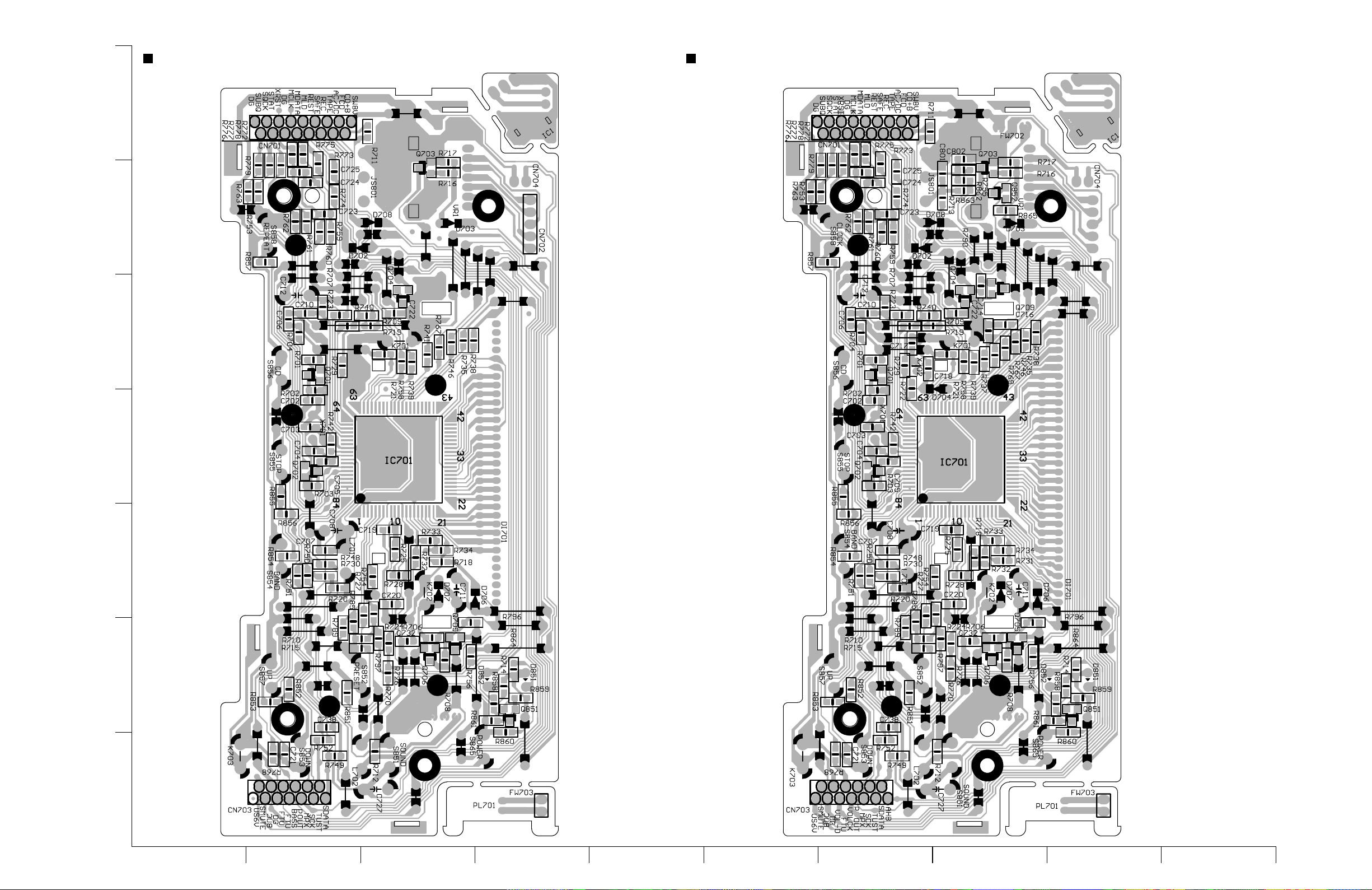
RC-BZ5LB/BZ5RD
RC-BZ6BU
System CPU board (RC-BZ5LB/BZ5RD) Block No.02
7
6
5
System CPU board (RC-BZ6BU) Block No.02
4
3
2
1
BCDEFGH I JA
2-10
Page 36

RC-BZ5LB/BZ5RD
PARTS LIST
[ RC-BZ5LB/BZ5RD ]
[ RC-BZ6BU ]
* All printed circuit boards and its assemblies are not available as service parts.
RC-BZ6BU
Areas suffix
J ----------------------------- U.S.A.
C -------------------------- Canada
- Contents - [RC-BZ5LB/BZ5RD]
Exploded view of general assembly and parts list
Cassette mechanism assembly and parts list
CD mechanism assembly and parts list
Electrical Parts List
Packing materials and accessories parts list
3-2
3-4
3-6
3-7
3-13
- Contents - [RC-BZ6BU]
Exploded view of general assembly and parts list
Cassette mechanism assembly and parts list
CD mechanism assembly and parts list
Electrical Parts List
Packing materials and accessories parts list
3-14
3-16
3-18
3-19
3-25
3-1
Page 37
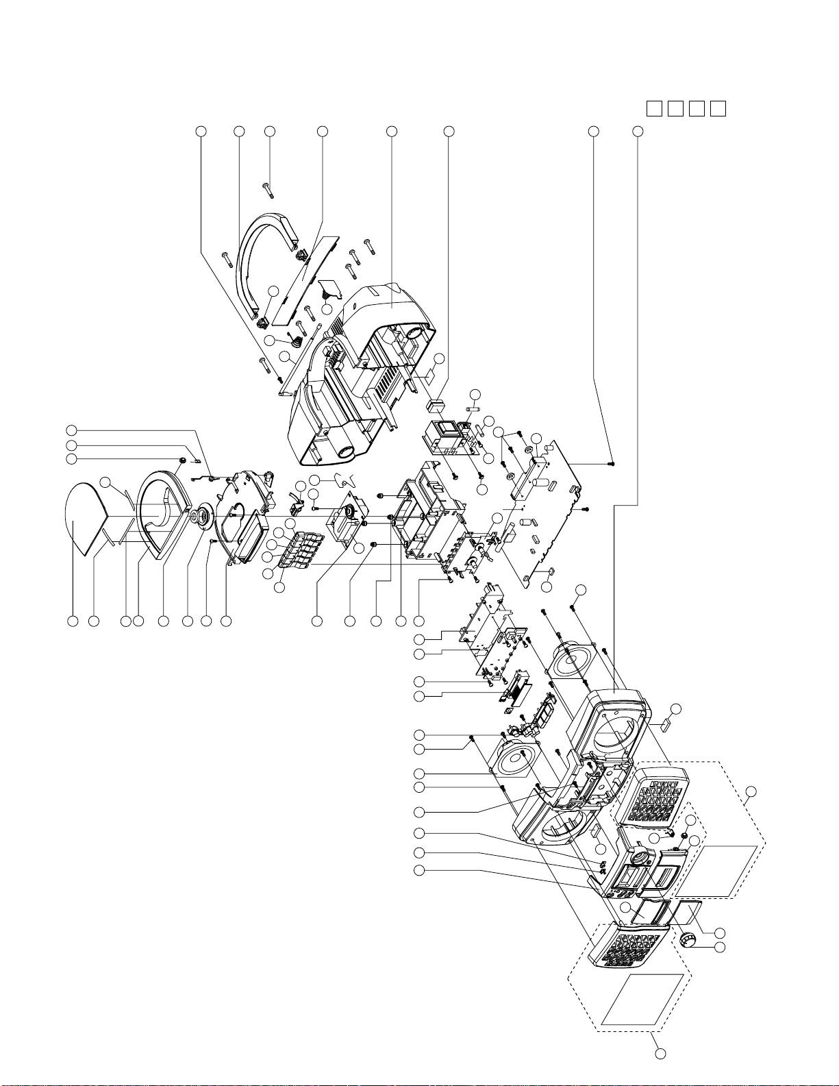
RC-BZ5LB/BZ5RD
Exploded view of general assembly and parts list
Block No.
16
Main board ass'y
67
68
Power
board ass'y
A
65
A
66
61
60
16
41
CD
mechanism
44
50
51
52
49
47
7034 54
CD door switch
board ass'y
3
48
Battery
board ass'y
64
46
43
10
63
M
38
M
1
M
11-6
11-5
11-4
11-3
11-2
11-1
1
2
5
6
4
8
7
9
12
62
13
14
15
55
17185520
23
2416 1625262728
Cassette
mechanism
Remote
40
board
ass'y
Key switch
/display
69
board ass'y
LCD
16
59
37
34
36
59
33
35
3-2
31 32
30
Page 38

RC-BZ5LB/BZ5RD
A
A
Parts list ( General assembly )
Item Parts number Parts name Area
A
1 GJ460340210101 LENS CD DOOR 1 RC-BZ5LB
GJ460340500101 LENS CD DOOR 1 RC-BZ5RD
2 GJ670000010330 D.SPACER 1 65X3.5
3 GJ670000010340 D.SPACER 1 65X3.5
4 GJ670000010350 D.SPACER 1 110-3.0
5 GJ460340120101 DOOR CD 1
6 VYH7313-005 MAGNET 1
7 LV30175-001A CLAMPER 1
8 GJ702224301242 SCREW TT3X12 2 FOR CD CASE
9 GJ460340160101 CD CASE 1
10 GJ460340020101 BUTTON 1 OPEN
11-1 GJ460340040101 BUTTON(A)MECHA. 1 PAUSE
11-2 GJ460340050101 BUTTON(B)MECHA. 1 STOP
11-3 GJ460340060101 BUTTON(C)MECHA. 1 FF
11-4 GJ460340070101 BUTTON(D)MECHA. 1 REW
11-5 GJ460340080101 BUTTON(E)MECHA. 1 PLAY
11-6 GJ460340090101 BUTTON(F)MECHA. 1 REC
12 --------------- CD UNIT EXL-M7B 1 GJA1005002001C
13 E75609-001 INSULATOR 2 CD MECHA RED
14 E75609-002 INSULATOR 2 CD MECHA PURPLE
15 GJ460340170101 HOLDER CD 1
16 GJ702244301012 SCREW TT3X10 20 SPEAKE/MAIN PCB
17 GJ460340200101 HOLDER 1 CONTROL BOARD
18 GJ781000090101 SHIELD PLATE 1
20 GJ460340270101 HOLDER (1)LCD 1
23 GJ460340230101 FUNCTION KNOB 1
24 LE10010-005A SPEAKER 2
25 GJ702244260812 SCREW TT2.6X8 2 COVER-FRONT
26 GJ460340030101 LENS 1 REMOTE SENSOR
27 GJ460340260101 LENS 1 LED
28 GJ460340400101 FRONT COVER 1
30 GJ0001-SPGR SPEAKER GRILLE 1 SHILD, RC-BZ5RD
GJ0003-SPGR SPEAKER GRILLE 1 SHILD, RC-BZ5LB
31 GJ460340250101 VOLUME KNOB 1
32 GJ460340490101 C.DOOR LENS 1 RC-BZ5RD
GJ460340190101 C.DOOR LENS 1 RC-BZ5LB
33 GJ460340220101 FRONT LENS 1 RC-BZ5LB
GJ460340480101 FRONT LENS 1 RC-BZ5RD
34 VYH8007-001 GEAR 2 DOOR
35 GJ460340180101 CASSETTE DOOR 1
36 LV40210-001A DOOR SPRING 1
37 GJ0002-SPGR SPEAKER GRILLE 1 SHILD, RC-BZ5RD
GJ0004-SPGR SPEAKER GRILLE 1 SHILD, RC-BZ5LB
38 GJ460340010101 FRONT CABINET 1
40 --------------- DECK MECHANISM 1 TN-21ZVC-1800
41 GJ702264301412 SCREW TT3X14 2
43 GJ711001340101 SPRING 1 ANT CONTACT
44 GJ460340100101 REAR CABINET 1
Q'ty Description
Block No. M1MM
Parts list ( General assembly )
Item Parts number Parts name Area
A
46 TA46174 T.PICK ANTENNA 1
47 VYH5657-006 BATTERY SPRING 1 SIZE D
48 LV20082-001A BATTERY COVER 1
49 VYH8008-001 HANDLE SUPPORT 2
50 GJ702244304512 SCREW TT3X45 8
51 GJ460340150101 HANDLE 1
52 GJ701224300852 SCREW M3X8 1 T. ANTENNA
54 GJ711001330201 SPRING 1
55 GJ702244300812 SCREW TT3X8 8 DECK/KEY P.C.B.
59 GJ782000090101 FOOT RUBBER 2
60 LV30176-001A HEAT SINK 1
61 QYSDSF3008Z SCREW 3 HEAT SINK
62 202-300002-00 CD COVER PLATE 1
63 GJ702224200642 SCREW TT2X6 4 CD COVER
64 VYH5483-001 BATTERY SPRING 1
65 QMF51N2-3R0-J1 FUSE
66 QMF51N2-3R0-J1 FUSE
67 GJ560340150101 NAME PLATE J,C1 RC-BZ5LB
GJ560340070101 NAME PLATE J,C1 RC-BZ5RD
68 GJ782000090101 RUBBER SPACER 1
69 GJ761000200100 SPACER 1
70 GJ500340240101 GEAR SPRING 1 CD DAMP
Q'ty Description
1 3A 125V F902
1 3A 125V F903
Block No. M1MM
3-3
Page 39

RC-BZ5LB/BZ5RD
Parts list ( Cassette mechanism assembly )
Item Parts number Parts name Area
A
1 192114316T BASE ASSY 1
2 19211409T SWITCH ACTUATOR 1
3 19211408T LOCK CAM 1
4 19211403T REC BUTT.LEVER 1
5 19211419T PLAY BUTT.LEVER 1
6 19211404T REW BUTT. LEVER 1
7 19211405T FF BUTTON LEVER 1
8 19211406T STOP BUTT.LEVER 1
9 19211460T PAUSE BUT.LEVER 1
10 19211413AT SPRING 1 PAUSE LEVER
11 19211455T PAUSE LEVER (E) 1
12 19211412T SPRING 1 PAUSE LEVER
13 19211411T PAUSE STOPPER 1
14 19211414T TORSION SPRING 1
15 192101501T CHASSIS ASS'Y 1
16 19211416T TORSION SPRING 1
17 19211417T TORSION SPRING 1
19 182101159T E.KICK LEVER 1
20 19211420T STOPPER 1
21 19211421T TORSION SPRING 1 REC BUTTON
22 19211415T TORSION SPRING 1 BUTTON LEVER
23 MSW-1541T LEAF SWITCH 1 MSW-1541T
24 18210150T TENSION SPRING 1 PLAY BUTTON
25 19210311T HEAD PANEL 1
26 19210304AT HEAD BASE 1
27 19210309T PANEL P SPRING 1
28 19210305T MAGNET HEAD ARM 1
29 18210307T AZIMUTH SPRING 1 AZIMUTH
30 19211418AT SPRING 1 M CONTROL
31 19210310T MG ARM SPRING 1 MG ARM
32 192104309T P.ROLLER ARM 1
35 19212604AT SENSING LEVER 1
36 19212605T TORSION SPRING 1 GEAR PLATE
37 192126502T GEAR PLATE 1
38 19212602T CAM GEAR 1
40 192107304T R.F.CLUTCH 1
41 19210703T REW/F.F. BELT 1
43 192109303T FLYWHEEL ASSY 1
45 18211070T F.FORWARD GEAR 1
46 18211099T BACK TENSION SP 1
47 192105304T S. REEL ASS'Y 1
48 192105303T T. REEL ASS'Y 1
49 19210506T SENSOR 1
51 18211289AT MOTOR BRACKET 1
53 19211202T COLLAR SCREW 2 SP MOTOR 3X6
54 19211201T MOTOR PULLEY 1
55 19210904T MAIN BELT 1
56 19211203T MB SCREW 1 SP M B 2X
Q'ty Description
Block No. M2MM
Parts list ( Cassette mechanism assembly )
Item Parts number Parts name Area
A
58 19211301T EJ. SLIDE LEVER 1
59 18211093T PACK SPRING 1
60 18211069T REC.SAF.LEVER 1
62 MS15R-AA2N1 R/P HEAD 1
63 PH-K380-MS1-6A ERASE HEAD 1
64 60020217T MOTOR 1
66 9P0420031T TAPPING SCREW 1 PACK SPRING
68 9B1020051T TAPPING SCREW 2 (M2 X 5)
69 9C0720451T TAPPING SCREW 2 (M2 X 4.5)
70 9B0120031T SCREW(+)BIND 1 (M2 X 3)
71 9P0120061T SCREW 1 (M2 X 6)
72 9F0820071T SCREW AZIMUTH 1 (M2 X 7)
75 9W0230010T P.CUT WASHER 1 (12X3.8X0.3)
76 9W0250010T P.CUT WASHER 1 (1.45X3.8X0.5)
77 9W0140010T P.CUT WASHER 1 (2X3.5X0.4)
78 9W0113020T P.CUT WASHER 1 (2X3.5X0.4)
80 19210201T REC ARM 1
81 19211437T P ARM COLLAR 2
82 64010138T LEAF SWITCH 1
83 9P0420041T SCREW 1 (M2 X 4)
84 9P0420051T SCREW 1 (M2 X 5)
85 19211434T P.ROLLER ARM 1
86 9P0820301T TAPPING SCREW 1 (M2 X 3)
Q'ty Description
Block No. M2MM
3-4
Page 40

Cassette mechanism assembly and parts list
TN-21ZVC-1800
Block No.
RC-BZ5LB/BZ5RD
M
M
2
M
Pulley hight dimension
7.6±0.1
3-5
Page 41

RC-BZ5LB/BZ5RD
CD mechanism assembly and parts list
Grease Point
G-31KB
(Grease to apply have
to be alittle for the
exchange)
16
4
Block No.
5
M
M
3
M
No.EXL-M7B
3
2
NOTE
Please order moutor after confirming the number
of the P.C.Board because the combination of feed
motor is different according to the P.C.Board used.
7
6
8
G-31KB
1
G-31KB
6
9
10
15
13
11
14
Parts list ( CD mechanism assembly )
Item Parts number Parts name Area
A
1 GJ560280020101 MECHA BASE 1
2 OPTIMA-7B CD PICK UP 1
3 E407782-001 PICK STAFT 1
4 E307746-001 CD RACK GEAR 1 GEAR SHAFT
5 GJ560280010101 MECHA GEAR 1
6 GJ50312003102 SCREW MZX3 B/H 4
7 E406750-001 PINION GEAR 1
8 GJA2062001001C CD TURN TABLE 1
9 GJ90028678400 FEED MOTOR 1
10 GJ90028678300 SPINDLE MOTOR 1
11 GJ100069000100 MECH CIR BOARD 1
13 GJ157208512 LEAF SWITCH 1
14 GJ50322623312 SPECIAL SCREW 1
15 GJ51206010101 6P PLUG ASSY 1
16 SDSF2006Z SCREW 1
Q'ty Description
Block No. M3MM
3-6
Page 42

RC-BZ5LB/BZ5RD
Electrical parts list ( Main board )
Item
A
C 3 GJ264130392101 C.CAPACITOR 50V SL K 3.9PF
C 6 GJ264271032101 C.CAPACITOR 16V Y M 0.01UF
C 7 GJ264141022101 C.CAPACITOR 50V B K 1000PF
C 9 GJ264031202101 A.CAPACITOR 50V SL J 12PF
C 13 GJ262102232402 C.CAPACITOR 25V YR K 0.022U
C 16 GJ264271032101 C.CAPACITOR 16V Y M 0.01UF
C 21 GJ262104732402 C.CAPACITOR 25V YR K 0.047U
C 22 GJ285214312415 M.CAPACITOR PP 100V J 430PF
C 23 GJ264081202101 C.CAPACITOR 50V CH J 12PF
C 31 GJ264141022101 C.CAPACITOR 50V B K 1000PF
C 32 GJ264271032101 C.CAPACITOR 16V Y M 0.01UF
C 33 GJ270111070332 E.CAPACITOR 10V M 100UF
C 35 GJ270191040332 E.CAPACITOR 50V M 0.1UF
C 36 GJ270194750332 E.CAPACITOR 50V VX M 4.7UF
C 37 GJ264141022101 C.CAPACITOR 50V B K 1000PF
C 38 GJ264271032101 C.CAPACITOR 16V Y M 0.01UF
C 40 GJ264271032101 C.CAPACITOR 16V Y M 0.01UF
C 41 GJ270194750332 E.CAPACITOR 50V VX M 4.7UF
C 42 GJ262104732402 C.CAPACITOR 25V YR K 0.047U
C 43 GJ270191040332 E.CAPACITOR 50V M 0.1UF
C 44 GJ270191050332 E.CAPACITOR 50V M 1UF
C 45 GJ270191040332 E.CAPACITOR 50V M 0.1UF
C 47 GJ262101532402 C.CAPACITOR 25V YR K 0.015U
C 48 GJ262101532402 C.CAPACITOR 25V YR K 0.015U
C 49 GJ270191040332 E.CAPACITOR 50V M 0.1UF
C 50 GJ270191040332 E.CAPACITOR 50V M 0.1UF
C 51 GJ264143312101 C.CAPACITOR 50V B K 330PF
C 52 GJ264141022101 C.CAPACITOR 50V B K 1000PF
C 56 GJ264141022101 C.CAPACITOR 50V B K 1000PF
C 60 GJ264141022101 C.CAPACITOR 50V B K 1000PF
C 61 GJ270111070332 E.CAPACITOR 10V M 100UF
C 62 GJ264081202101 C.CAPACITOR 50V CH J 12PF
C 63 GJ264141022101 C.CAPACITOR 50V B K 1000PF
C 64 GJ264081202101 C.CAPACITOR 50V CH J 12PF
C 65 GJ264141022101 C.CAPACITOR 50V B K 1000PF
C 69 GJ264262222101 A.CAPACITOR 16V X M 0.0022U
C 70 GJ270192250332 E.CAPACITOR 50V M 2.2UF
C 71 GJ270121060332 E.CAPACITOR 16V M 10UF
C 77 GJ264141022101 C.CAPACITOR 50V B K 1000PF
C 98 GJ264141012101 C.CAPACITOR 50V B K 100PF
C 99 GJ264141012101 C.CAPACITOR 50V B K 100PF
C 101 GJ283101022432 M.CAPACITOR POLY FILM 50V K
C 102 GJ283105622432 M.CAPACITOR POLY FILM 50V K
C 103 GJ270122260332 E.CAPACITOR 16V M 22UF
C 104 GJ282033932415 M.CAPACITOR FILM 50V J 0.03
C 105 GJ270193350332 E.CAPACITOR 50V M 3.3UF
C 107 GJ270194750332 E.CAPACITOR 50V VX M 4.7UF
C 108 GJ270191050332 E.CAPACITOR 50V M 1UF
C 114 GJ270194750332 E.CAPACITOR 50V VX M 4.7UF
C 119 GJ270194740332 E.CAPACITOR 50V M 0.47UF
C 120 GJ270121070332 E.CAPACITOR 100UF 16V VX M
C 121 GJ264142212101 C.CAPACITOR 50V B K 220PF
C 122 GJ270121070332 E.CAPACITOR 100UF 16V VX M
C 123 GJ270121080132 E.CAPACITOR 1000UF16V VX
C 124 GJ283101042432 M.CAPACITOR POLY FILM 50V K
C 130 GJ260772212412 C.CAPACITOR 50V SL J 220PF
C 132 GJ270194740332 E.CAPACITOR 50V M 0.47UF
C 133 GJ270114760332 E.CAPACITOR 10V M 47UF
C 155 GJ264141812101 C.CAPACITOR 50V B K 180PF
C 156 GJ283108222432 M.CAPACITOR POLY FILM 50V K
C 157 GJ283101542432 M.CAPACITOR POLY FILM 50V K
C 201 GJ283101022432 M.CAPACITOR POLY FILM 50V K
C 202 GJ283105622432 M.CAPACITOR POLY FILM 50V K
Parts number Parts name Area
Remarks
Block No. 01
Item
A
C 203 GJ270122260332 E.CAPACITOR 16V M 22UF
C 204 GJ282033932415 M.CAPACITOR FILM 50V J 0.03
C 205 GJ270193350332 E.CAPACITOR 50V M 3.3UF
C 207 GJ270194750332 E.CAPACITOR 50V VX M 4.7UF
C 208 GJ270191050332 E.CAPACITOR 50V M 1UF
C 214 GJ270194750332 E.CAPACITOR 50V VX M 4.7UF
C 219 GJ270194740332 E.CAPACITOR 50V M 0.47UF
C 220 GJ270121070332 E.CAPACITOR 100UF 16V VX M
C 221 GJ264142212101 C.CAPACITOR 50V B K 220PF
C 222 GJ270121070332 E.CAPACITOR 100UF 16V VX M
C 223 GJ270121080132 E.CAPACITOR 1000UF16V VX
C 224 GJ283101042432 M.CAPACITOR POLY FILM 50V K
C 230 GJ260772212412 C.CAPACITOR 50V SL J 220PF
C 232 GJ270194740332 E.CAPACITOR 50V M 0.47UF
C 233 GJ270114760332 E.CAPACITOR 10V M 47UF
C 255 GJ264141812101 C.CAPACITOR 50V B K 180PF
C 256 GJ283108222432 M.CAPACITOR POLY FILM 50V K
C 257 GJ283101542432 M.CAPACITOR POLY FILM 50V K
C 303 GJ260771512412 C.CAPACITOR 50V SL J 150PF
C 304 GJ270114760332 E.CAPACITOR 10V M 47UF
C 305 GJ270122260332 E.CAPACITOR 16V M 22UF
C 306 GJ270114760332 E.CAPACITOR 10V M 47UF
C 308 GJ260771812412 C.CAPACITOR 50V SL J 180PF
C 309 GJ264261822101 C.CAPACITOR 16V X M 0.0018U
C 310 GJ283101822432 M.CAPACITOR POLY FILM 50V K
C 312 GJ283106822432 M.CAPACITOR POLY FILM 50V K
C 313 GJ270114760332 E.CAPACITOR 10V M 47UF
C 315 GJ283104722432 M.CAPACITOR POLY FILM 50V K
C 318 GJ270143380132 E.CAPACITOR 25V VX M 3300UF
C 319 GJ270141060332 E.CAPACITOR 25V M 10UF
C 320 GJ270122270332 E.CAPACITOR 16V M 220UF
C 322 GJ264141022101 C.CAPACITOR 50V B K 1000PF
C 331 GJ264141022101 C.CAPACITOR 50V B K 1000PF
C 350 GJ270194750332 E.CAPACITOR 50V VX M 4.7UF
C 353 GJ270121060332 E.CAPACITOR 16V M 10UF
C 354 GJ270112270332 E.CAPACITOR 10V M 220UF
C 357 GJ270122260332 E.CAPACITOR 16V M 22UF
C 604 GJ270111070332 E.CAPACITOR 10V M 100UF
C 605 GJ270141060332 E.CAPACITOR 25V M 10UF
C 606 GJ264141022101 C.CAPACITOR 50V B K 1000PF
C 607 GJ264141022101 C.CAPACITOR 50V B K 1000PF
C 608 GJ270191050332 E.CAPACITOR 50V M 1UF
C 609 GJ264141012101 C.CAPACITOR 50V B K 100PF
C 610 GJ282032732415 M.CAPACITOR FILM 50V J 0.02
C 611 GJ264264722101 A.CAPACITOR 16V X M 0.0047U
C 612 GJ264271032101 C.CAPACITOR 16V Y M 0.01UF
C 613 GJ264143312101 C.CAPACITOR 50V B K 330PF
C 614 GJ282031042415 M.CAPACITOR FILM 50V J 0.1U
C 615 GJ264182232101 C.CAPACITOR 25V F Z 0.022UF
C 616 GJ264182232101 C.CAPACITOR 25V F Z 0.022UF
C 617 GJ264182232101 C.CAPACITOR 25V F Z 0.022UF
C 618 GJ264262222101 A.CAPACITOR 16V X M 0.0022U
C 619 GJ264142712101 A.CAPACITOR 50V B K 270PF
C 620 GJ264141812101 C.CAPACITOR 50V B K 180PF
C 622 GJ270114760332 E.CAPACITOR 10V M 47UF
C 623 GJ282031042415 M.CAPACITOR FILM 50V J 0.1U
C 628 GJ262104732402 C.CAPACITOR 25V YR K 0.047U
C 629 GJ270111070332 E.CAPACITOR 10V M 100UF
C 631 GJ270114770332 E.CAPACITOR 10V M 470UF
C 632 GJ270111070332 E.CAPACITOR 10V M 100UF
C 640 GJ264278222101 C.CAPACITOR 16V X M 0.0082U
C 641 GJ264182232101 C.CAPACITOR 25V F Z 0.022UF
C 651 GJ264032202101 C.CAPACITOR 50V SL J 22PF
Parts number Parts name Area
Remarks
3-7
Page 43

RC-BZ5LB/BZ5RD
Q
Q
Q
Q
Q
Q
Q
Q
Q
Q
Q
Q
Q
Q
Q
Q
Q
Q
Q
Electrical parts list ( Main board )
Item
A
C 652 GJ264032202101 C.CAPACITOR 50V SL J 22PF
C 653 GJ264182232101 C.CAPACITOR 25V F Z 0.022UF
C 655 GJ262104732402 C.CAPACITOR 25V YR K 0.047U
C 661 GJ264144712101 C.CAPACITOR 50V B K 470PF
C 662 GJ264182232101 C.CAPACITOR 25V F Z 0.022UF
C 663 GJ282032232415 M.CAPACITOR FILM 50V J 0.02
C 664 GJ264182232101 C.CAPACITOR 25V F Z 0.022UF
C 665 GJ282031042415 M.CAPACITOR FILM 50V J 0.1U
C 671 GJ264262222101 A.CAPACITOR 16V X M 0.0022U
C 672 GJ264262222101 A.CAPACITOR 16V X M 0.0022U
C 673 GJ270112270332 E.CAPACITOR 10V M 220UF
C 674 GJ264182232101 C.CAPACITOR 25V F Z 0.022UF
C 675 GJ264141022101 C.CAPACITOR 50V B K 1000PF
C 690 GJ264271032101 C.CAPACITOR 16V Y M 0.01UF
C 691 GJ264141512101 C.CAPACITOR 50V B K 150PF
C 692 GJ264141512101 C.CAPACITOR 50V B K 150PF
C 693 GJ264141512101 C.CAPACITOR 50V B K 150PF
C 694 GJ264141512101 C.CAPACITOR 50V B K 150PF
C 695 GJ264271032101 C.CAPACITOR 16V Y M 0.01UF
C 696 GJ264141012101 C.CAPACITOR 50V B K 100PF
C 697 GJ264141012101 C.CAPACITOR 50V B K 100PF
C 698 GJ264141012101 C.CAPACITOR 50V B K 100PF
C 699 GJ264141012101 C.CAPACITOR 50V B K 100PF
C 709 GJ270102280132 E.CAPACITOR 6.3V VX M 2200U
C 901 GJ262772232412 C.CAPACITOR 50V F Z 0.022UF
C 902 GJ262772232412 C.CAPACITOR 50V F Z 0.022UF
C 903 GJ262772232412 C.CAPACITOR 50V F Z 0.022UF
C 904 GJ262772232412 C.CAPACITOR 50V F Z 0.022UF
C 905 GJ264271032101 C.CAPACITOR 16V Y M 0.01UF
C 906 GJ264271032101 C.CAPACITOR 16V Y M 0.01UF
C 908 GJ264271032101 C.CAPACITOR 16V Y M 0.01UF
C 909 GJ270194750332 E.CAPACITOR 50V VX M 4.7UF
C 910 GJ270112270332 E.CAPACITOR 10V M 220UF
C 911 GJ270122260332 E.CAPACITOR 16V M 22UF
C 912 GJ264271032101 C.CAPACITOR 16V Y M 0.01UF
C 913 GJ264271032101 C.CAPACITOR 16V Y M 0.01UF
C 914 GJ270112270332 E.CAPACITOR 10V M 220UF
C 915 GJ270111070332 E.CAPACITOR 10V M 100UF
C 916 GJ270114760332 E.CAPACITOR 10V M 47UF
CF 1 QAX0403-001 C FILTER CER FM 10.7M
CF 3 QAX0538-001Z CRYSTAL CER FM CDA10.7
CN301 GJ156450711 CONNECTOR 4PINS ST RED
CN303 QGF1212C1-12 FFC CONNECTOR 12PINS
CN304 QGF1212C1-17 FFC CONNECTOR 17PINS
CN306 TID-X03P-MI CONNECTOR 3 PINS RA WHIT
CN307 5268-03A CONNECTOR 3PINS RA
CN308 GJ156450911 CONNECTOR 6PINS ST WHITE
CN309 GJ158016511 TRANSISTOR 4PIN ST WHITE
CN310 QGA2501C3-03Z CONNECTOR IM GJ156450611
CN601 QGF1025C1-15 21-41 CONNECTOR 15PINS
D 1 SVC203SPA-JV-T VARI CAP GJ310050080104
D 2 SVC203SPA-JV-T VARI CAP GJ310050080104
D 5 1SS133Y DIODE GJ871999133
D 6 1SS133Y DIODE GJ871999133
D 8 KV1555N-T VARI CAPACITOR GJ310050040103
D 12 IN4001 DIODE RECT BULK
D 303 1SS133Y DIODE GJ871999133
D 305 1SS133Y DIODE GJ871999133
D 307 1SS133Y DIODE GJ871999133
D 661 1SS133Y DIODE GJ871999133
D 901 1N5401-M SI DIODE
A
D 902 1N5401-M SI DIODE
A
D 903 1N5401-M SI DIODE
A
Parts number Parts name Area
Remarks
Block No. 01
Item
A
D 904 1N5401-M SI DIODE
A
D 905 1SS133Y DIODE GJ871999133
D 907 1SS133Y DIODE GJ871999133
D 908 1SS133Y DIODE GJ871999133
D 909 1SS133Y DIODE GJ871999133
D 910 1SS133Y DIODE GJ871999133
D 911 1SS133Y DIODE GJ871999133
D 912 IN4001 DIODE RECT BULK
D 914 1SS133Y DIODE GJ871999133
D 915 1SS133Y DIODE GJ871999133
D 916 1SS133Y DIODE GJ871999133
D 917 1SS133Y DIODE GJ871999133
D 918 1SS133Y DIODE GJ871999133
D 995 1SS133Y DIODE GJ871999133
FC902 GJ153321741 FUSE HOLDER
FC903 GJ153321741 FUSE HOLDER
FC905 GJ153321741 FUSE HOLDER
FC906 GJ153321741 FUSE HOLDER
FW 1 GJ353120150107 CARD WIRE CN303 TO CN703
FW 2 VWF1015-08TTA CARD WIRE CN601 TO CD
FW 3 GJ353170240107 CARD WIRE CN304 TO CN701
IC 1 TA2104AN IC DIP
IC 2 LC72136N IC PLL IC
IC301 TA2068N IC DIP PRE/REC AMP
IC302 LA4597K IC
A
IC601 AN8806SB IC RF AMP
IC602 BA6897FP IC POWER DRIVER
IC603 MN35510 IC 1 CHIP PROCISSE
IC703 GP1U281X IC GJ313010541005
J 9 QNC0043-001 AC SOCKET
A
J 301 GJ342010200113 JACK H/P MSJ2000 (BL
K 1 QQR0779-001Z INDUCTOR GJVQZ0048009
K 601 QQR0779-001Z INDUCTOR GJVQZ0048009
K 602 QQR0779-001Z INDUCTOR GJVQZ0048009
L 1 VQF1B20-019 OSC COIL FM OSC
L 2 VQC1505-002L RF COIL GJ320020260109
L 3 VQB008M-506 BAR ANTENA GJVQB008M506
L 4 QQR0723-001 OSC COIL IFT AM OSC 7.5
L 7 VQP0018-221 INDUCTOR 220UH 10% Q40
L 10 QQL231K-4R7Y INDUCTOR 4.7UH
L 12 V03047-17L INDUCTOR GJ320080140109
L 601 3A839N INDUCTOR 10UH RADIAL LEA
L 602 GJ141033431 INDUCTOR 100UH 10% Q40
L 901 VQP0028-330Z INDUCTOR 33UH
Parts number Parts name Area
1 2SC2668/O/T TRANSISTOR GJ312020351201
101 2SC2001/LK/-T TRANSISTOR GJ872914247
111 2SC2458/YG/-T TRANSISTOR GJ872923044
112 2SC2458/YG/-T TRANSISTOR GJ872923044
201 2SC2001/LK/-T TRANSISTOR GJ872914247
211 2SC2458/YG/-T TRANSISTOR GJ872923044
212 2SC2458/YG/-T TRANSISTOR GJ872923044
302 KRA102M-T D.TRANSISTOR GJ872903715
303 2SC2458/YG/-T TRANSISTOR GJ872923044
304 2SA1015/YG/-T TRANSISTOR GJ872923115
305 KRC102M-T D.TRANSISTOR GJ872903658
306 8550C TRANSISTOR GJ312080042204
308 DTC143ES TRANSISTOR DTC143ES-TP
309 2SC2458/YG/-T TRANSISTOR GJ872923044
310 DTA143ESA-T D.TR.I.M DTA143ESA-TP
311 2SC2001/LK/-T TRANSISTOR GJ872914247
312 2SC2001/LK/-T TRANSISTOR GJ872914247
313 2SC2001/LK/-T TRANSISTOR GJ872914247
315 2SC2458/YG/-T TRANSISTOR GJ872923044
Remarks
DIP SB-S1150
125V 7A
3-8
Page 44

RC-BZ5LB/BZ5RD
Q
Q
Q
Q
Q
Q
Q
Q
Q
Q
Q
Q
Q
Q
Q
Electrical parts list ( Main board )
Item
A
A
A
A
A
R 1 GJ250081042103 CARBON RESISTOR CF 1/6W J 100K
R 2 GJ250084732103 CARBON RESISTOR CF 1/6W J 47K
R 3 GJ250082702103 CARBON RESISTOR CF 1/6W J 27
R 4 GJ250084732103 CARBON RESISTOR CF 1/6W J 47K
R 7 GJ250081042103 CARBON RESISTOR CF 1/6W J 100K
R 9 GJ250084722103 CARBON RESISTOR CF 1/6W J 4.7K
R 13 GJ250081042103 CARBON RESISTOR CF 1/6W J 100K
R 18 GJ250081022103 CARBON RESISTOR CF 1/6W J 1K
R 20 GJ250081022103 CARBON RESISTOR CF 1/6W J 1K
R 24 GJ250086812103 CARBON RESISTOR CF 1/6W J 680
R 25 GJ250081022103 CARBON RESISTOR CF 1/6W J 1K
R 30 GJ250081832103 CARBON RESISTOR CF 1/6W J 18K
R 31 GJ250081042103 CARBON RESISTOR CF 1/6W J 100K
R 32 GJ250083322103 CARBON RESISTOR CF 1/6W J 3.3K
R 33 GJ250083312103 CARBON RESISTOR CF 1/6W J 330
R 35 GJ250082732103 CARBON RESISTOR CF 1/6W J 27K
R 36 GJ250082732103 CARBON RESISTOR CF 1/6W J 27K
R 37 GJ250085602103 CARBON RESISTOR CF 1/6W J 56
R 38 GJ250081012103 CARBON RESISTOR CF 1/6W J 100
R 39 GJ250081212103 CF RESISTOR CF 1/6W J 120
R 42 GJ250084732103 CARBON RESISTOR CF 1/6W J 47K
R 44 GJ250082222103 CARBON RESISTOR CF 1/6W J 2.2K
R 47 GJ250082202103 CARBON RESISTOR CF 1/6W J 22
R 48 GJ250081022103 CARBON RESISTOR CF 1/6W J 1K
R 49 GJ250081832103 CARBON RESISTOR CF 1/6W J 18K
R 50 GJ250081832103 CARBON RESISTOR CF 1/6W J 18K
R 52 GJ250081032103 CARBON RESISTOR CF 1/6W J 10K
R 54 GJ250082222103 CARBON RESISTOR CF 1/6W J 2.2K
R 55 GJ250082222103 CARBON RESISTOR CF 1/6W J 2.2K
R 56 GJ250083322103 CARBON RESISTOR CF 1/6W J 3.3K
R 57 GJ250081022103 CARBON RESISTOR CF 1/6W J 1K
R 59 GJ250081022103 CARBON RESISTOR CF 1/6W J 1K
R 60 GJ250081022103 CARBON RESISTOR CF 1/6W J 1K
R 61 GJ250081022103 CARBON RESISTOR CF 1/6W J 1K
R 63 GJ250084732103 CARBON RESISTOR CF 1/6W J 47K
R 64 GJ250081022103 CARBON RESISTOR CF 1/6W J 1K
R 104 GJ250083322103 CARBON RESISTOR CF 1/6W J 3.3K
R 106 GJ250083932103 CF RESISTOR CF 1/6W J 39K
R 107 GJ250088202103 RES CF CF 1/6W J 82
R 108 GJ250081532103 CARBON RESISTOR CF 1/6W J 15K
R 119 GJ250081042103 CARBON RESISTOR CF 1/6W J 100K
R 121 GJ250088202103 RES CF CF 1/6W J 82
R 122 GJ250082292103 C.RESISTOR CF 1/6W J 2.2
R 123 GJ250081012103 CARBON RESISTOR CF 1/6W J 100
R 124 GJ250082222103 CARBON RESISTOR CF 1/6W J 2.2K
R 125 GJ250081032103 CARBON RESISTOR CF 1/6W J 10K
R 127 GJ250083322103 CARBON RESISTOR CF 1/6W J 3.3K
R 131 GJ250081832103 CARBON RESISTOR CF 1/6W J 18K
Parts number Parts name Area
316 2SA1015/YG/-T TRANSISTOR GJ872923115
317 2SC2458/YG/-T TRANSISTOR GJ872923044
318 DTA143ESA-T D.TR.I.M DTA143ESA-TP
601 2SA952/LK/-T TRANSISTOR TAPE
631 2SA952/LK/-T TRANSISTOR TAPE
851 2SA1037AK/RS/-X TRANSISTOR GJ872902649
901 2SB772/QP/ TRANSISTOR
902 2SC2458/YG/-T TRANSISTOR GJ872923044
903 8550C TRANSISTOR
904 2SC2458/YG/-T TRANSISTOR GJ872923044
906 8550C TRANSISTOR
907 2SC2458/YG/-T TRANSISTOR GJ872923044
908 2SB772/QP/ TRANSISTOR
909 2SC2458/YG/-T TRANSISTOR GJ872923044
911 2SC2458/YG/-T TRANSISTOR GJ872923044
GJ312070021102
GJ312080042204
GJ312080042204
GJ312070021102
Remarks
Block No. 01
Item
A
R 132 GJ250081032103 CARBON RESISTOR CF 1/6W J 10K
R 133 GJ250081822103 CARBON RESISTOR CF 1/6W J 1.8K
R 134 GJ250083922103 CARBON RESISTOR CF 1/6W J 3.9K
R 135 GJ250084732103 CARBON RESISTOR CF 1/6W J 47K
R 137 GJ250086822103 CARBON RESISTOR CF 1/6W J 6.8K
R 204 GJ250083322103 CARBON RESISTOR CF 1/6W J 3.3K
R 206 GJ250083932103 CF RESISTOR CF 1/6W J 39K
R 207 GJ250088202103 RES CF CF 1/6W J 82
R 208 GJ250081532103 CARBON RESISTOR CF 1/6W J 15K
R 219 GJ250081042103 CARBON RESISTOR CF 1/6W J 100K
R 221 GJ250088202103 RES CF CF 1/6W J 82
R 222 GJ250082292103 C.RESISTOR CF 1/6W J 2.2
R 223 GJ250081012103 CARBON RESISTOR CF 1/6W J 100
R 224 GJ250082222103 CARBON RESISTOR CF 1/6W J 2.2K
R 225 GJ250081032103 CARBON RESISTOR CF 1/6W J 10K
R 227 GJ250083322103 CARBON RESISTOR CF 1/6W J 3.3K
R 231 GJ250081832103 CARBON RESISTOR CF 1/6W J 18K
R 232 GJ250081032103 CARBON RESISTOR CF 1/6W J 10K
R 233 GJ250081822103 CARBON RESISTOR CF 1/6W J 1.8K
R 234 GJ250083922103 CARBON RESISTOR CF 1/6W J 3.9K
R 235 GJ250084732103 CARBON RESISTOR CF 1/6W J 47K
R 237 GJ250086822103 CARBON RESISTOR CF 1/6W J 6.8K
R 302 GJ250081032103 CARBON RESISTOR CF 1/6W J 10K
R 303 GJ250084752103 RES CF CF 1/6W J 4.7M
R 304 GJ250081032103 CARBON RESISTOR CF 1/6W J 10K
R 305 GJ250081822103 CARBON RESISTOR CF 1/6W J 1.8K
R 306 GJ250081822103 CARBON RESISTOR CF 1/6W J 1.8K
R 307 GJ250083322103 CARBON RESISTOR CF 1/6W J 3.3K
R 310 GJ250081232103 CARBON RESISTOR CF 1/6W J 12K
R 311 GJ250081012103 CARBON RESISTOR CF 1/6W J 100
R 312 GJ250084312103 C.RESISTOR CF 1/6W J 430
R 313 GJ250081202103 C.RESISTOR CF 1/6W J 12
R 316 GJ250083322103 CARBON RESISTOR CF 1/6W J 3.3K
R 317 GJ250081032103 CARBON RESISTOR CF 1/6W J 10K
R 318 GJ250081012103 CARBON RESISTOR CF 1/6W J 100
R 320 GJ250085622103 CARBON RESISTOR CF 1/6W J 5.6K
R 321 GJ250085622103 CARBON RESISTOR CF 1/6W J 5.6K
R 328 GJ250081032103 CARBON RESISTOR CF 1/6W J 10K
R 332 GJ250081032103 CARBON RESISTOR CF 1/6W J 10K
R 356 GJ250081032103 CARBON RESISTOR CF 1/6W J 10K
R 360 GJ250081032103 CARBON RESISTOR CF 1/6W J 10K
R 361 GJ250084742103 CARBON RESISTOR CF 1/6W J 470K
R 371 GJ250081032103 CARBON RESISTOR CF 1/6W J 10K
R 372 GJ250083322103 CARBON RESISTOR CF 1/6W J 3.3K
R 373 GJ250081012103 CARBON RESISTOR CF 1/6W J 100
R 601 GJ250081132103 CARBON RESISTOR CF 1/6W J 11K
R 603 GJ250081252103 FUSE RESISTOR CF 1/6W J 1.2M
R 605 GJ250082742103 CARBON RESISTOR CF 1/6W J 270K
R 606 GJ250081542103 CARBON RESISTOR CF 1/6W J 150K
R 607 GJ250082732103 CARBON RESISTOR CF 1/6W J 27K
R 609 GJ250081042103 CARBON RESISTOR CF 1/6W J 100K
R 610 GJ250081542103 CARBON RESISTOR CF 1/6W J 150K
R 612 GJ250081022103 CARBON RESISTOR CF 1/6W J 1K
R 613 GJ250081212103 CF RESISTOR CF 1/6W J 120
R 614 GJ250081002103 CARBON RESISTOR CF 1/6W J 10
R 615 GJ250081202103 C.RESISTOR CF 1/6W J 12
R 616 GJ250089102103 CARBON RESISTOR CF 1/6W J 91
R 621 GJ250083302103 CARBON RESISTOR CF 1/6W J 33
R 622 GJ250083302103 CARBON RESISTOR CF 1/6W J 33
R 623 GJ250083302103 CARBON RESISTOR CF 1/6W J 33
R 631 GJ250083312103 CARBON RESISTOR CF 1/6W J 330
R 632 GJ250081012103 CARBON RESISTOR CF 1/6W J 100
R 633 GJ250082732103 CARBON RESISTOR CF 1/6W J 27K
Parts number Parts name Area
Remarks
3-9
Page 45

RC-BZ5LB/BZ5RD
Electrical parts list ( Main board )
Item
A
R 641 GJ250085632103 CARBON RESISTOR CF 1/6W J 56K
R 642 GJ250081232103 CARBON RESISTOR CF 1/6W J 12K
R 643 GJ250088222103 CARBON RESISTOR CF 1/6W J 8.2K
R 644 GJ250082232103 CARBON RESISTOR CF 1/6W J 22K
R 645 GJ250082232103 CARBON RESISTOR CF 1/6W J 22K
R 646 GJ250082222103 CARBON RESISTOR CF 1/6W J 2.2K
R 647 GJ250084722103 CARBON RESISTOR CF 1/6W J 4.7K
R 651 GJ250081022103 CARBON RESISTOR CF 1/6W J 1K
R 652 GJ250081022103 CARBON RESISTOR CF 1/6W J 1K
R 653 GJ250081022103 CARBON RESISTOR CF 1/6W J 1K
R 654 GJ250081022103 CARBON RESISTOR CF 1/6W J 1K
R 659 GJ250082712103 CARBON RESISTOR CF 1/6W J 270
R 661 GJ250086832103 CF RESISTOR CF 1/6W J 68K
R 663 GJ250081242103 CARBON RESISTOR CF 1/6W J 120K
R 664 GJ250084712103 CARBON RESISTOR CF 1/6W J 470
R 666 GJ250082202103 CARBON RESISTOR CF 1/6W J 22
R 671 GJ250081022103 CARBON RESISTOR CF 1/6W J 1K
R 672 GJ250081022103 CARBON RESISTOR CF 1/6W J 1K
R 696 GJ250082222103 CARBON RESISTOR CF 1/6W J 2.2K
R 697 GJ250084742103 CARBON RESISTOR CF 1/6W J 470K
R 901 GJ250084722103 CARBON RESISTOR CF 1/6W J 4.7K
R 902 GJ250085632103 CARBON RESISTOR CF 1/6W J 56K
R 903 GJ250081012103 CARBON RESISTOR CF 1/6W J 100
R 904 GJ250088212103 CARBON RESISTOR CF 1/6W J 820
R 906 GJ250085632103 CARBON RESISTOR CF 1/6W J 56K
R 907 GJ250081022103 CARBON RESISTOR CF 1/6W J 1K
R 908 GJ250083322103 CARBON RESISTOR CF 1/6W J 3.3K
R 909 GJ250081022103 CARBON RESISTOR CF 1/6W J 1K
R 910 GJ250081042103 CARBON RESISTOR CF 1/6W J 100K
R 911 GJ250084722103 CARBON RESISTOR CF 1/6W J 4.7K
R 912 GJ250081022103 CARBON RESISTOR CF 1/6W J 1K
R 913 GJ250085622103 CARBON RESISTOR CF 1/6W J 5.6K
R 914 QRZ0077-4R7X FUSE RESISTOR
A
R 915 GJ250081012103 CARBON RESISTOR CF 1/6W J 100
R 916 GJ250088212103 CARBON RESISTOR CF 1/6W J 820
R 917 GJ250082202103 CARBON RESISTOR CF 1/6W J 22
R 919 GJ250085632103 CARBON RESISTOR CF 1/6W J 56K
R 920 GJ250084722103 CARBON RESISTOR CF 1/6W J 4.7K
R 922 GJ250081032103 CARBON RESISTOR CF 1/6W J 10K
R 998 GJ251273352201 C RESISTOR 1/2W 3.3M 5%
R 999 GJ250083312103 CARBON RESISTOR 1/6W J 330
S 301 MSW-17820MVD0 LEAF SWITCH GJ390140041114
S 303 SK-23E01-G9 SLIDE SWITCH SLIDE SIDE
T 2 GJ123388511 IFT 7MM BLACKPCFAZT 9 GJ336570400003 POWER TRANS.
A
T 301 OH-812320 BIAS OSC COIL GJ321000140101
TC 2 QAT3722-200ZM T CAPACITOR TRIMMER 20PF EC
TP 2 VMZ0015-002 POST PIN FM ANT PIN SOCK
WR 1 GJ354003940105 WIRE CN308 TO DECK
WR 2 GJ354003960205 WIRE POWER TO BATT.
WR 3 GJ354003980205 WIRE CN309 TO SPEAKE
WR 4 GJ354003990405 WIRE FW301 TO POWER
WR 5 GJ354004000105 WIRE CN301 TO HEAD
WR 6 GJ351004020105 WIRE CN602 TO CD ME.
X 1 QAX0402-001 CRYSTAL 75KHZ +/-20PPM
X 651 CSA16.93MXZ040T CERA LOCK CER CSA
ZD 1 MTZ3.0JB Z.DIODE GJ871998307
ZD903 MTZJ6.2B-T2 ZENER DIODE GJ871992342
ZD904 MTZJ5.6B Z DIODE GJ310030011305
ZD905 MTZJ7.5C-T2 ZENER DIODE GJ310030015005
Parts number Parts name Area
Remarks
1/4W J 4.7 TAPE
EI-57 AC120V
Block No. 01
3-10
Page 46

RC-BZ5LB/BZ5RD
Q
Q
Q
Q
Q
Q
Electrical parts list ( System CPU board )
Item
A
C 702 GJ116323691 C.CAPACITOR 24PF CH 2012 5%
C 703 GJ116324091 C.CAPACITOR 36PF CH 2012 Z
C 704 GJ116324091 C.CAPACITOR 36PF CH 2012 Z
C 705 GJ116323691 C.CAPACITOR 24PF CH 2012 5%
C 706 GJ116300991 C.CAPASISTOR 1000PF B 2012 1
C 707 GJ116303891 C.CAPACITOR 100000PF F 2012
C 708 GJ270112270332 E.CAPACITOR 10V M 220UF
C 710 GJ116302191 C.CAPASISTOR 10000PF B 2012
C 711 GJ112423391 E.CAPACITOR 16V M 10UF
C 712 GJ112425791 E.CAPACITOR 50V M 2.2UF
C 719 GJ116300991 C.CAPASISTOR 1000PF B 2012 1
C 720 GJ116300991 C.CAPASISTOR 1000PF B 2012 1
C 721 GJ116302191 C.CAPASISTOR 10000PF B 2012
C 722 GJ116311791 C.CAPACITOR 100PF SL 2012 5
C 723 GJ116311791 C.CAPACITOR 100PF SL 2012 5
C 724 GJ116311791 C.CAPACITOR 100PF SL 2012 5
C 725 GJ116311791 C.CAPACITOR 100PF SL 2012 5
C 727 GJ112678591 E.CAPACITOR 10V M 47UF
C 732 GJ116303891 C.CAPACITOR 100000PF F 2012
C 738 GJ116312191 C.CAPACITOR 150PF SL 2012 5
CN701 QGF1212F1-17 FFC/FPC CONNE 17PINS
CN702 GJ156450811 CONNECTOR 5 PIN
CN703 QGF1212F1-12 FFC CONNE 12PINS
CN704 GJ156451711 CONNECTOR 2PINS RA
D 702 1SS133Y DIODE GJ871999133
D 703 UZ5.1BSC-T2 ZENER DIODE MTZJ5.1B-T77
D 706 1SS133Y DIODE GJ871999133
D 707 1SS133Y DIODE GJ871999133
D 708 1SS133Y DIODE GJ871999133
D 851 LT0311G-41 LED GREEN STAND STAND BY/RED CO
D 852 LT0321-41 ON LED RTP ON /GREEN COLOR
DI701 GJ373010282311 L C D DLC-9833P
IC701 GJ313010671223 IC MICOM MN171603Y
K 701 QQR0779-001Z INDUCTOR GJVQZ0048009
K 702 QQR0779-001Z INDUCTOR GJVQZ0048009
K 703 QQR0779-001Z INDUCTOR GJVQZ0048009
L 701 3A839N INDUCTOR 10UH K RADIAL L
L 702 3A839N INDUCTOR 10UH K RADIAL L
R 701 GJ121604991 C.RESISTOR 1K 1/10W 5%
R 702 GJ121607191 C.RESISTOR 8.2K 1/10W 5%
R 703 GJ121607191 C.RESISTOR 8.2K 1/10W 5%
R 704 GJ121604991 C.RESISTOR 1K 1/10W 5%
R 706 GJ121607391 C.RESISTOR 10K 1/10W 5%
R 707 GJ121607391 C.RESISTOR 10K 1/10W 5%
R 708 GJ121607391 C.RESISTOR 10K 1/10W 5%
R 709 GJ121608191 C.RESISTOR 22K 1/10W 5%
R 710 GJ121609791 C.RESISTOR 100K 1/10W 5%
R 711 GJ121608191 C.RESISTOR 22K 1/10W 5%
R 712 GJ121607391 C.RESISTOR 10K 1/10W 5%
R 714 GJ121608791 C.RESISTOR 39K 1/10W 5%
R 715 GJ121608591 C.RESISTOR 33K 1/10W 5%
R 716 GJ121608991 C.RESISTOR 47K 1/10W 5%
R 717 GJ121608591 C.RESISTOR 33K 1/10W 5%
R 718 GJ121607391 C.RESISTOR 10K 1/10W 5%
R 719 GJ121609791 C.RESISTOR 100K 1/10W 5%
R 720 GJ121609791 C.RESISTOR 100K 1/10W 5%
R 721 GJ121605791 C.RESISTOR 2.2K 1/10W 5%
Parts number Parts name Area
701 2SC2714/O/-X TRANSISTOR GJ312020341203
702 2SC2714/O/-X TRANSISTOR GJ312020341203
703 2SC2412K/R/-X TRANSISTOR GJ872992075
704 DTC144EKA-X TRANSISTOR GJ872902759
705 2SA1037AK/RS/-X TRANSISTOR GJ872902649
706 DTC143TKA-X DIGI TRANSISTOR GJ872902756
Remarks
Block No. 02
Item
A
R 723 GJ121607391 C.RESISTOR 10K 1/10W 5%
R 724 GJ121605791 C.RESISTOR 2.2K 1/10W 5%
R 725 GJ121605791 C.RESISTOR 2.2K 1/10W 5%
R 726 GJ121605791 C.RESISTOR 2.2K 1/10W 5%
R 727 GJ121605791 C.RESISTOR 2.2K 1/10W 5%
R 728 GJ121607391 C.RESISTOR 10K 1/10W 5%
R 729 GJ121608991 C.RESISTOR 47K 1/10W 5%
R 730 GJ121607391 C.RESISTOR 10K 1/10W 5%
R 732 GJ121609791 C.RESISTOR 100K 1/10W 5%
R 733 GJ121609791 C.RESISTOR 100K 1/10W 5%
R 734 GJ121609791 C.RESISTOR 100K 1/10W 5%
R 735 GJ121607391 C.RESISTOR 10K 1/10W 5%
R 738 GJ121607391 C.RESISTOR 10K 1/10W 5%
R 739 GJ121608191 C.RESISTOR 22K 1/10W 5%
R 740 GJ121607391 C.RESISTOR 10K 1/10W 5%
R 741 GJ121607391 C.RESISTOR 10K 1/10W 5%
R 742 GJ121605791 C.RESISTOR 2.2K 1/10W 5%
R 746 GJ121608191 C.RESISTOR 22K 1/10W 5%
R 748 GJ121608191 C.RESISTOR 22K 1/10W 5%
R 749 GJ121608991 C.RESISTOR 47K 1/10W 5%
R 750 GJ121607391 C.RESISTOR 10K 1/10W 5%
R 751 GJ121607391 C.RESISTOR 10K 1/10W 5%
R 752 GJ121607391 C.RESISTOR 10K 1/10W 5%
R 753 GJ121605791 C.RESISTOR 2.2K 1/10W 5%
R 754 GJ121607391 C.RESISTOR 10K 1/10W 5%
R 756 GJ121608191 C.RESISTOR 22K 1/10W 5%
R 758 GJ121605791 C.RESISTOR 2.2K 1/10W 5%
R 759 GJ121604991 C.RESISTOR 1K 1/10W 5%
R 760 GJ121604991 C.RESISTOR 1K 1/10W 5%
R 761 GJ121605791 C.RESISTOR 2.2K 1/10W 5%
R 762 GJ121605791 C.RESISTOR 2.2K 1/10W 5%
R 763 GJ121605791 C.RESISTOR 2.2K 1/10W 5%
R 767 GJ121606591 C.RESISTOR 4.7K 1/10W 5%
R 768 GJ121607391 C.RESISTOR 10K 1/10W 5%
R 770 GJ121605791 C.RESISTOR 2.2K 1/10W 5%
R 772 GJ121604991 C.RESISTOR 1K 1/10W 5%
R 773 GJ121607391 C.RESISTOR 10K 1/10W 5%
R 774 GJ121604991 C.RESISTOR 1K 1/10W 5%
R 775 GJ121604991 C.RESISTOR 1K 1/10W 5%
R 776 GJ121604991 C.RESISTOR 1K 1/10W 5%
R 777 GJ121604991 C.RESISTOR 1K 1/10W 5%
R 778 GJ121604991 C.RESISTOR 1K 1/10W 5%
R 779 GJ121604991 C.RESISTOR 1K 1/10W 5%
R 785 GJ121605791 C.RESISTOR 2.2K 1/10W 5%
R 796 GJ121609791 C.RESISTOR 100K 1/10W 5%
R 797 GJ121606591 C.RESISTOR 4.7K 1/10W 5%
R 851 GJ121605391 C.RESISTOR 1.5K 1/10W 5%
R 852 GJ121605591 C.RESISTOR 1.8K 1/10W 5%
R 853 GJ121605991 C.RESISTOR 2.7K 1/10W 5%
R 854 GJ121606391 C.RESISTOR 3.9K 1/10W 5%
R 855 GJ121606991 C.RESISTOR 6.8K 1/10W 5%
R 856 GJ121607591 C.RESISTOR 12K 1/10W 5%
R 857 GJ121608791 C.RESISTOR 39K 1/10W 5%
R 858 GJ121606791 C.RESISTOR 5.6K 1/10W 5%
R 859 GJ121607991 C.RESISTOR 18K 1/10W 5%
R 860 GJ121603791 C.RESISTOR 330 1/10W 5%
R 861 GJ121604591 C.RESISTOR 680 1/10W 5%
R 864 GJ121606791 C.RESISTOR 5.6K 1/10W 5%
S 851 QSW0707-001Z TACT SWITCH GJ390110171110
S 852 QSW0707-001Z TACT SWITCH GJ390110171110
S 853 QSW0707-001Z TACT SWITCH GJ390110171110
S 854 QSW0707-001Z TACT SWITCH GJ390110171110
S 855 QSW0707-001Z TACT SWITCH GJ390110171110
Parts number Parts name Area
Remarks
3-11
Page 47

RC-BZ5LB/BZ5RD
Electrical parts list ( System CPU board )
Item
A
S 856 QSW0707-001Z TACT SWITCH GJ390110171110
S 857 QSW0707-001Z TACT SWITCH GJ390110171110
S 858 QSW0707-001Z TACT SWITCH GJ390110171110
S 865 QSW0707-001Z TACT SWITCH GJ390110171110
S 866 GJ390030152203 SWITCH PUSH SW PSG-22F0US-Q3.5
VR302 QVQ0121-A54 MAIN VOL GJ299000490002
WR701 GJ354004030205 WIRE CN704 TO CD DO.
WR702 GJ354004040105 WIRE CN702 TO MAIN
X 701 QAX0410-001Z CERA LOCK MIZCRHF 4.19MHZ
Parts number Parts name Area
Remarks
Block No. 02
3-12
Page 48

Packing materials and accessories parts list
RC-BZ5LB/BZ5RD
A1
P6
P1
P5
P3
P8
Block No.
Block No.
M
M
A2~A7
P4
A8
P7
A9
P2
A10
M
4
5
M
M
M
Packing parts list
Item Parts number Parts name Area
A
P 1 GJ560340040101 CUSHION (L) 1
P 2 GJ560340050101 CUSHION (R) 1
P 3 GJ560340140101 CARTON WALL 1 RC-BZ5RD
GJ560340130101 CARTON WALL 1 RC-BZ5LB
P 4 QPA02503503P POLY BAG 1 250 X 350
P 5 GJ740456520300 POLYBAG PE 1 450 X 650
P 6 QPA01503503 POLY BAG 1 150 X 350
P 7 QPA01202505 POLY BAG 1 120 X 250
P 8 LV30189-001A CARTON LABEL 1
Q'ty Description
Accessories parts list
Item Parts number Parts name Area
A
A 1 GJ350161831129 POWER CORD
A 2 GJ773012200101 INTRUCTIONS J,C1 ENG SPA FRE
A 3 BT-20044G ACC SAFETY GUID J,C1 GJ775000140101
A 4 GJ775000200202 SERVICE LIST J,C1
A 5 GJ775000340101 SVC CENTER LIST J,C1
A 6 GJ773030190302 WARRANTY CARD J1
A 7 GJ773030290101 WARRANTY CARD C1
A 8 GJA1002014001C REMOCON UNIT 1
A 9 GJ460340320102 BATTER COVER 1 REMOTE CONTROL
Q'ty Description
1 7A 120V 1.80M
Block No. M4MM
Block No. M5MM
3-13
Page 49

RC-BZ6BU
Exploded view of general assemble and parts list
Block No.
50
51
52
49
47
48
Battery
board ass'y
64
46
44
68
67
16
M
38
M
1
M
A
65
board ass'y
A
66
61
16
41
60
Main board ass'y
Power
7034 54
CD door switch
board ass'y
43
3
10
63
CD
mechanism
11-6
11-5
11-4
11-3
11-2
11-1
1
2
5
6
4
8
7
9
12
62
13
14
15
58
17185820555657
23
2416 1625262728
Cassette
mechanism
40
Remote
board
ass'y
Key switch
/display
69
board ass'y
LCD
16
59
37
34
36
59
33
35
3-14
31 32
30
Page 50

RC-BZ6BU
A
Parts list ( General assembly )
Item Parts number Parts name Area
A
1 GJ460340470101 LENS CD DOOR 1
2 GJ670000010330 D.SPACER 1 65X3.5
3 GJ670000010340 D.SPACER 1 65X3.5
4 GJ670000010350 D.SPACER 1 110-3.0
5 GJ460340120101 DOOR CD 1
6 VYH7313-005 MAGNET 1
7 LV30175-001A CLAMPER 1
8 GJ702224301242 SCREW TT3X12 2 FOR CD CASE
9 GJ460340160101 CD CASE 1
10 GJ460340020101 BUTTON 1
11-1 GJ460340040101 BUTTON(A)MECHA. 1 PAUSE
11-2 GJ460340050101 BUTTON(B)MECHA. 1 STOP
11-3 GJ460340060101 BUTTON(C)MECHA. 1 FF
11-4 GJ460340070101 BUTTON(D)MECHA. 1 REW
11-5 GJ460340080101 BUTTON(E)MECHA. 1 PLAY
11-6 GJ460340090101 BUTTON(F)MECHA. 1 REC
12 --------------- CD UNIT EXL-M7B 1 GJA1005002001C
13 E75609-001 INSULATOR 2 CD MECHA RED
14 E75609-002 INSULATOR 2 CD MECHA PURPLE
15 GJ460340170101 HOLDER CD 1
16 GJ702244301012 SCREW TT3X10 20 SPEAKE/MAIN PCB
17 GJ460340200101 HOLDER 1 CONTROL BOARD
18 GJ781000090101 SHIELD PLATE 1
20 GJ460340280101 HOLDER(2) 1 LCD
23 GJ460340230101 FUNCTION KNOB 1
24 LE10010-005A SPEAKER 2
25 GJ702244260812 SCREW TT2.6X8 2 COVER-FRONT
26 GJ460340030101 LENS 1 REMOTE SENSOR
27 GJ460340260101 LENS 1 LED
28 GJ460340290101 FRONT COVER 1
30 GJ0005-SPGR SPEAKER GRILLE 1 SHILD
31 GJ460340240101 VOLUME KNOB 1
32 GJ460340190101 C.DOOR LENS 1
33 GJ460340220101 FRONT LENS 1
34 VYH8007-001 GEAR DANPER 2 DOOR
35 GJ460340180101 CASSETTE DOOR 1
36 LV40210-001A DOOR SPRING 1
37 GJ0006-SPGR SPEAKER GRILLE 1 SHILD
38 GJ460340010101 FRONT CABINET 1
40 --------------- DECK MECHANISM 1 TN-21ZVC-1800
41 GJ702264301412 SCREW TT3X14 2
43 GJ711001340101 SPRING 1 ANT CONTACT
44 GJ460340100101 REAR CABINET 1
46 TA46174 T.PICK ANTENNA 1
47 VYH5657-006 BATTERY SPRING 1 SIZE D
48 LV20082-001A BATTERY COVER 1
49 VYH8008-001 HANDLE SUPPORT
Q'ty Description
2
Block No. M1MM
Parts list ( General assembly )
Item Parts number Parts name Area
A
50 GJ702244304512 SCREW TT3X45 8
51 GJ460340150101 HANDLE 1
52 GJ701224300852 SCREW M3X8 1
54 GJ711001330201 SPRING 1
55 LV40379-001A LCD LENS 2 1
56 LV40213-001A LCD SHEET 1
57 LV40200-001A LCD LENS 1
58 GJ702244300812 SCREW TT3X8 8
59 GJ782000090101 FOOT RUBBER 2
60 LV30176-001A HEAT SINK 1
61 QYSDSF3008Z SCREW 3 HEAT SINK
62 202-300002-00 CD COVER PLATE 1
63 GJ702224200642 SCREW TT2X6 4 CD COVER
64 VYH5483-001 BATTERY SPRING 1
65 QMF51N2-3R0-J1 FUSE
A
66 QMF51N2-3R0-J1 FUSE
67 GJ560340060101 NAME PLATE J,C1
68 GJ782000090101 RUBBER SPACER 1
69 GJ761000200100 SPACER 1
70 GJ500340240101 GEAR SPRING 1 CD DAMP
Q'ty Description
1 3A 125V F902
1 3A 125V F903
Block No. M1MM
3-5
3-15
Page 51

RC-BZ6BU
Parts list ( Cassette mechanism assembly )
Item Parts number Parts name Area
A
1 192114316T BASE ASSY 1
2 19211409T SWITCH ACTUATOR 1
3 19211408T LOCK CAM 1
4 19211403T REC BUTT.LEVER 1
5 19211419T PLAY BUTT.LEVER 1
6 19211404T REW BUTT. LEVER 1
7 19211405T FF BUTTON LEVER 1
8 19211406T STOP BUTT.LEVER 1
9 19211460T PAUSE BUT.LEVER 1
10 19211413AT SPRING 1 PAUSE LEVER
11 19211455T PAUSE LEVER (E) 1
12 19211412T SPRING 1 PAUSE LEVER
13 19211411T PAUSE STOPPER 1
14 19211414T TORSION SPRING 1
15 192101501T CHASSIS ASS'Y 1
16 19211416T TORSION SPRING 1
17 19211417T TORSION SPRING 1
19 182101159T E.KICK LEVER 1
20 19211420T STOPPER 1
21 19211421T TORSION SPRING 1 REC BUTTON
22 19211415T TORSION SPRING 1 BUTTON LEVER
23 MSW-1541T LEAF SWITCH 1 640101149T
24 18210150T TENSION SPRING 1 PLAY BUTTON
25 19210311T HEAD PANEL 1
26 19210304AT HEAD BASE 1
27 19210309T PANEL P SPRING 1
28 19210305T MAGNET HEAD ARM 1
29 18210307T AZIMUTH SPRING 1 AZIMUTH
30 19211418AT SPRING 1 M CONTROL
31 19210310T MG ARM SPRING 1 MG ARM
32 192104309T P.ROLLER ARM 1
35 19212604AT SENSING LEVER 1
36 19212605T TORSION SPRING 1 GEAR PLATE
37 192126502T GEAR PLATE 1
38 19212602T CAM GEAR 1
40 192107304T R.F.CLUTCH 1
41 19210703T REW/F.F. BELT 1
43 192109303T FLYWHEEL ASSY 1
45 18211070T F.FORWARD GEAR 1
46 18211099T BACK TENSION SP 1
47 192105304T S. REEL ASS'Y 1
48 192105303T T. REEL ASS'Y 1
49 19210506T SENSOR 1
51 18211289AT MOTOR BRACKET 1
53 19211202T COLLAR SCREW 2 SP MOTOR 3X6
54 19211201T MOTOR PULLEY 1
55 19210904T MAIN BELT 1
56 19211203T MB SCREW 1 SP MB 2X
Q'ty Description
Block No. M2MM
Parts list ( Cassette mechanism assembly )
Item Parts number Parts name Area
A
58 19211301T EM. SLIDE LEVER 1
59 18211093T PACK SPRING 1 GJ711000820103
60 18211069T RECK.SAF.LEVER 1
62 MS15R-AA2N1 R/P.HEAD 1
63 PH-K380-MS1-6A ERASE HEAD 1 GJ382070110003
64 60020217T MOTOR 1
66 9P0420031T TAPPING SCREW 1 PACK SPRING
68 9B1020051T TAPPING SCREW 2 (Ma X 5)
69 9C0720451T TAPPING SCREW 2 (Ma X 4.5)
70 9B0120031T SCREW (+)BIND 1 (Ma X 3)
71 9P0120061T SCREW 1 (Ma X 6)
72 9F0820071T SCREW AZIMUTH 1 (Ma X 7)
75 9W0230010T P.CUT WASHER 1 (12X3.8X0.3)
76 9W0250010T P.CUT WASHER 1 (1.45X3.8X0.5)
77 9W0140010T P.CUT WASHER 1 (2X3.5X0.4)
78 9W0113020T P.CUT WASHER 1 (2X3.5X0.4)
80 19210201T RECK ARM 1
81 19211437T P ARM COLLAR 2
82 64010138T LEAF SWITCH 1
83 9P0420041T C TAPPING SCREW 1 (Ma X 4)
84 9P0420051T C TAPPING SCREW 1 (Ma X 5)
85 19211434T P.ROLLER ARM 1
86 9P0820301T PA TAPPIN.SCREW 1 (Ma X 3)
Q'ty Description
Block No. M2MM
3-6
3-16
Page 52

Cassette mechanism assembly and parts list
TN-21ZVC-1800
Block No.
M
RC-BZ6BU
M
2
M
Pulley hight dimension
7.6±0.1
3-17
Page 53

RC-BZ6BU
CD mechanism assembly and parts list
Grease Point
G-31KB
(Grease to apply have
to be alittle for the
exchange)
16
4
Block No.
5
M
M
3
M
No.EXL-M7B
3
2
NOTE
Please order moutor after confirming the number
of the P.C.Board because the combination of feed
motor is different according to the P.C.Board used.
7
6
8
G-31KB
1
G-31KB
6
9
10
15
13
11
14
Parts list ( CD mechanism assembly )
Item Parts number Parts name Area
A
1 GJ560280020101 MECHA BASE 1
2 OPTIMA-7B C.D PICK 1
3 E407782-001 PICK STAFT 1
4 E307746-001 CD RACK GEAR 1 GEAR SHAFT
5 GJ560280010101 MECHA GEAR 1
6 GJ50312003102 SCREW MZX3 B/H 4
7 E406750-001 PINION GEAR 1
8 GJA2062001001C CD TURN TABLE 1
9 GJ90028678400 FEED MOTOR 1
10 GJ90028678300 SPINDLE MOTOR 1
11 EMW10190-001/S/ MECH CIR BOARD 1
13 GJ157208512 LEAF SWITCH 1
14 GJ50322623312 SPECIAL SCREW 1
15 GJ51206010101 6P PLUG ASSY 1
16 SDSF2006Z SCREW 1
Q'ty Description
Block No. M3MM
3-18
Page 54

RC-BZ6BU
Electrical parts list ( Main board )
Item
A
C 3 GJ264130392101 C.CAPACITOR 50V SL K 3.9PF
C 6 GJ264271032101 C.CAPACITOR 16V Y M 0.01UF
C 7 GJ264141022101 C.CAPACITOR 50V B K 1000PF
C 9 GJ264031202101 A.CAPACITOR 50V SL J 12PF
C 13 GJ262102232402 C.CAPACITOR 25V YR K 0.022U
C 16 GJ264271032101 C.CAPACITOR 16V Y M 0.01UF
C 21 GJ262104732402 C.CAPACITOR 25V YR K 0.047U
C 22 GJ285214312415 M.CAPACITOR PP 100V J 430PF
C 23 GJ264081202101 C.CAPACITOR 50V CH J 12PF
C 31 GJ264141022101 C.CAPACITOR 50V B K 1000PF
C 32 GJ264271032101 C.CAPACITOR 16V Y M 0.01UF
C 33 GJ270111070332 E.CAPACITOR 10V M VX 100UF
C 35 GJ270191040332 E.CAPACITOR 50V M 0.1UF
C 36 GJ270194750332 E.CAPACITOR 50V M 4.7UF
C 37 GJ264141022101 C.CAPACITOR 50V B K 1000PF
C 38 GJ264271032101 C.CAPACITOR 16V Y M 0.01UF
C 40 GJ264271032101 C.CAPACITOR 16V Y M 0.01UF
C 41 GJ270194750332 E.CAPACITOR 50V M 4.7UF
C 42 GJ262104732402 C.CAPACITOR 25V YR K 0.047U
C 43 GJ270191040332 E.CAPACITOR 50V M 0.1UF
C 44 GJ270191050332 E.CAPACITOR 50V M 1UF
C 45 GJ270191040332 E.CAPACITOR 50V M 0.1UF
C 47 GJ262101532402 C.CAPACITOR 25V YR K 0.015U
C 48 GJ262101532402 C.CAPACITOR 25V YR K 0.015U
C 49 GJ270191040332 E.CAPACITOR 50V M 0.1UF
C 50 GJ270191040332 E.CAPACITOR 50V M 0.1UF
C 51 GJ264143312101 C.CAPACITOR AXIAL 50V B K 3
C 52 GJ264141022101 C.CAPACITOR 50V B K 1000PF
C 56 GJ264141022101 C.CAPACITOR 50V B K 1000PF
C 60 GJ264141022101 C.CAPACITOR 50V B K 1000PF
C 61 GJ270111070332 E.CAPACITOR 10V M VX 100UF
C 62 GJ264081202101 C.CAPACITOR 50V CH J 12PF
C 63 GJ264141022101 C.CAPACITOR 50V B K 1000PF
C 64 GJ264081202101 C.CAPACITOR 50V CH J 12PF
C 65 GJ264141022101 C.CAPACITOR 50V B K 1000PF
C 69 GJ264262222101 A.CAPACITOR 16V X M 0.0022U
C 70 GJ270192250332 E.CAPACITOR 50V M 2.2UF
C 71 GJ270121060332 E.CAPACITOR 16V M 10UF
C 77 GJ264141022101 C.CAPACITOR 50V B K 1000PF
C 98 GJ264141012101 C.CAPACITOR 50V B K 100PF
C 99 GJ264141012101 C.CAPACITOR 50V B K 100PF
C 101 GJ283101022432 M.CAPACITOR 50V K 0.001UF
C 102 GJ283105622432 M.CAPACITOR 50V K 0.0056UF
C 103 GJ270122260332 E.CAPACITOR 16V M 22UF
C 104 GJ282033932415 M.CAPACITOR 50V J 0.039UF
C 107 GJ270194750332 E.CAPACITOR 50V M 4.7UF
C 108 GJ270191050332 E.CAPACITOR 50V M 1UF
C 109 GJ283108232432 M.CAPACITOR 50V K 0.082UF
C 110 GJ283108232432 M.CAPACITOR 50V K 0.082UF
C 111 GJ283106822432 M.CAPACITOR 50V K 0.0068UF
C 112 GJ282034742415 M.CAPACITOR 50V J 0.47UF
C 113 GJ283102232432 M.CAPACITOR 50V K 0.022UF
C 114 GJ270122260332 E.CAPACITOR 16V M 22UF
C 115 GJ270191040332 E.CAPACITOR 50V M 0.1UF
C 117 GJ270191050332 E.CAPACITOR 50V M 1UF
C 119 GJ270194750332 E.CAPACITOR 50V M 4.7UF
C 120 GJ270121070332 E.CAPACITOR 16V M 100UF
C 121 GJ264142212101 C.CAPACITOR 50V B K 220PF
C 122 GJ270121070332 E.CAPACITOR 16V M 100UF
C 123 GJ270122280132 E.CAPACITOR 16V M 2200UF
C 124 GJ283101042432 M.CAPACITOR 50V K 0.1UF
C 125 GJ270122260332 E.CAPACITOR 16V M 22UF
C 130 GJ260772212412 C.CAPACITOR C 50V SL J 220P
Parts number Parts name Area
Remarks
Block No. 01
Item
A
C 134 GJ283105622432 M.CAPACITOR 50V K 0.0056UF
C 155 GJ264141812101 C.CAPACITOR 50V B K 180PF
C 201 GJ283101022432 M.CAPACITOR 50V K 0.001UF
C 202 GJ283105622432 M.CAPACITOR 50V K 0.0056UF
C 203 GJ270122260332 E.CAPACITOR 16V M 22UF
C 204 GJ282033932415 M.CAPACITOR 50V J 0.039UF
C 207 GJ270194750332 E.CAPACITOR 50V M 4.7UF
C 208 GJ270191050332 E.CAPACITOR 50V M 1UF
C 209 GJ283108232432 M.CAPACITOR 50V K 0.082UF
C 210 GJ283108232432 M.CAPACITOR 50V K 0.082UF
C 211 GJ283106822432 M.CAPACITOR 50V K 0.0068UF
C 212 GJ282034742415 M.CAPACITOR 50V J 0.47UF
C 213 GJ283102232432 M.CAPACITOR 50V K 0.022UF
C 214 GJ270122260332 E.CAPACITOR 16V M 22UF
C 215 GJ270191040332 E.CAPACITOR 50V M 0.1UF
C 217 GJ270191050332 E.CAPACITOR 50V M 1UF
C 219 GJ270194750332 E.CAPACITOR 50V M 4.7UF
C 220 GJ270121070332 E.CAPACITOR 16V M 100UF
C 221 GJ264142212101 C.CAPACITOR 50V B K 220PF
C 222 GJ270121070332 E.CAPACITOR 16V M 100UF
C 223 GJ270122280132 E.CAPACITOR 16V M 2200UF
C 224 GJ283101042432 M.CAPACITOR 50V K 0.1UF
C 225 GJ270122260332 E.CAPACITOR 16V M 22UF
C 230 GJ260772212412 C.CAPACITOR C 50V SL J 220P
C 234 GJ283105622432 M.CAPACITOR 50V K 0.0056UF
C 255 GJ264141812101 C.CAPACITOR 50V B K 180PF
C 303 GJ260771512412 C.CAPACITOR 50V SL J 150PF
C 304 GJ270114760332 E.CAPACITOR 10V M 47UF
C 305 GJ270122260332 E.CAPACITOR 16V M 22UF
C 306 GJ270114760332 E.CAPACITOR 10V M 47UF
C 308 GJ260771812412 C.CAPACITOR 50V SL J 180PF
C 309 GJ264261822101 C.CAPACITOR 16V X M 0.0018U
C 310 GJ283101822432 M.CAPACITOR 50V K 0.0018UF
C 312 GJ283106822432 M.CAPACITOR 50V K 0.0068UF
C 313 GJ270114760332 E.CAPACITOR 10V M 47UF
C 315 GJ283104722432 M.CAPACITOR 50V K 0.0047UF
C 318 GJ270146880132 E.CAPACITOR 25V VX M 6800UF
C 319 GJ270141060332 E.CAPACITOR 25V M 10UF
C 320 GJ270122270332 E.CAPACITOR 16V M 220UF
C 321 GJ270111070332 E.CAPACITOR 10V M VX 100UF
C 322 GJ264141022101 C.CAPACITOR 50V B K 1000PF
C 323 GJ270111070332 E.CAPACITOR 10V M VX 100UF
C 324 GJ283101022432 M.CAPACITOR 50V K 0.001UF
C 325 GJ270111070332 E.CAPACITOR 10V M VX 100UF
C 326 GJ270111070332 E.CAPACITOR 10V M VX 100UF
C 327 GJ270111070332 E.CAPACITOR 10V M VX 100UF
C 328 GJ270191050332 E.CAPACITOR 50V M 1UF
C 329 GJ270191040332 E.CAPACITOR 50V M 0.1UF
C 330 GJ270194750332 E.CAPACITOR 50V M 4.7UF
C 350 GJ270194750332 E.CAPACITOR 50V M 4.7UF
C 353 GJ270121060332 E.CAPACITOR 16V M 10UF
C 354 GJ270112270332 E.CAPACITOR 10V M 220UF
C 357 GJ270122260332 E.CAPACITOR 16V M 22UF
C 371 GJ264141022101 C.CAPACITOR 50V B K 1000PF
C 604 GJ270111070332 E.CAPACITOR 10V M VX 100UF
C 605 GJ270141060332 E.CAPACITOR 25V M 10UF
C 606 GJ264141022101 C.CAPACITOR 50V B K 1000PF
C 607 GJ264141022101 C.CAPACITOR 50V B K 1000PF
C 608 GJ270191050332 E.CAPACITOR 50V M 1UF
C 609 GJ264141012101 C.CAPACITOR 50V B K 100PF
C 610 GJ282032732415 M.CAPACITOR 50V J 0.027UF
C 611 GJ264264722101 A.CAPACITOR 16V X M 0.0047U
C 612 GJ264271032101 C.CAPACITOR 16V Y M 0.01UF
Parts number Parts name Area
Remarks
3-19
Page 55

RC-BZ6BU
Electrical parts list ( Main board )
Item
A
C 613 GJ264143312101 C.CAPACITOR AXIAL 50V B K 3
C 614 GJ282031042415 M.CAPACITOR 50V J 0.1UF
C 615 GJ264182232101 C.CAPACITOR 25V F Z 0.022UF
C 616 GJ264182232101 C.CAPACITOR 25V F Z 0.022UF
C 617 GJ264182232101 C.CAPACITOR 25V F Z 0.022UF
C 618 GJ264262222101 A.CAPACITOR 16V X M 0.0022U
C 619 GJ264142712101 A.CAPACITOR AXIAL 50V B K 2
C 620 GJ264141812101 C.CAPACITOR 50V B K 180PF
C 622 GJ270114760332 E.CAPACITOR 10V M 47UF
C 623 GJ282031042415 M.CAPACITOR 50V J 0.1UF
C 628 GJ262104732402 C.CAPACITOR 25V YR K 0.047U
C 629 GJ270111070332 E.CAPACITOR 10V M VX 100UF
C 631 GJ270114770332 E.CAPACITOR 10V M 470UF
C 632 GJ270111070332 E.CAPACITOR 10V M VX 100UF
C 640 GJ264278222101 C.CAPACITOR 16V X M 0.0082U
C 641 GJ264182232101 C.CAPACITOR 25V F Z 0.022UF
C 651 GJ264032202101 C.CAPACITOR 50V SL J 22PF
C 652 GJ264032202101 C.CAPACITOR 50V SL J 22PF
C 653 GJ264182232101 C.CAPACITOR 25V F Z 0.022UF
C 655 GJ262104732402 C.CAPACITOR 25V YR K 0.047U
C 661 GJ264144712101 C.CAPACITOR 50V B K 470PF
C 662 GJ264182232101 C.CAPACITOR 25V F Z 0.022UF
C 663 GJ282032232415 M.CAPACITOR 50V J 0.022UF
C 664 GJ264182232101 C.CAPACITOR 25V F Z 0.022UF
C 665 GJ282031042415 M.CAPACITOR 50V J 0.1UF
C 671 GJ264262222101 A.CAPACITOR 16V X M 0.0022U
C 672 GJ264262222101 A.CAPACITOR 16V X M 0.0022U
C 673 GJ270112270332 E.CAPACITOR 10V M 220UF
C 674 GJ264182232101 C.CAPACITOR 25V F Z 0.022UF
C 675 GJ264141022101 C.CAPACITOR 50V B K 1000PF
C 676 GJ264141022101 C.CAPACITOR 50V B K 1000PF
C 690 GJ264271032101 C.CAPACITOR 16V Y M 0.01UF
C 691 GJ264141512101 C.CAPACITOR 50V B K 150PF
C 692 GJ264141512101 C.CAPACITOR 50V B K 150PF
C 693 GJ264141512101 C.CAPACITOR 50V B K 150PF
C 694 GJ264141512101 C.CAPACITOR 50V B K 150PF
C 695 GJ264271032101 C.CAPACITOR 16V Y M 0.01UF
C 696 GJ264141012101 C.CAPACITOR 50V B K 100PF
C 697 GJ264141012101 C.CAPACITOR 50V B K 100PF
C 698 GJ264141012101 C.CAPACITOR 50V B K 100PF
C 699 GJ264141012101 C.CAPACITOR 50V B K 100PF
C 709 GJ270102280132 E.CAPACITOR 6.3V M 2200UF
C 901 GJ262772232412 C.CAPACITOR 50V F Z 0.022UF
C 902 GJ262772232412 C.CAPACITOR 50V F Z 0.022UF
C 903 GJ262772232412 C.CAPACITOR 50V F Z 0.022UF
C 904 GJ262772232412 C.CAPACITOR 50V F Z 0.022UF
C 905 GJ264271032101 C.CAPACITOR 16V Y M 0.01UF
C 906 GJ264271032101 C.CAPACITOR 16V Y M 0.01UF
C 908 GJ264271032101 C.CAPACITOR 16V Y M 0.01UF
C 909 GJ270194750332 E.CAPACITOR 50V M 4.7UF
C 910 GJ270112270332 E.CAPACITOR 10V M 220UF
C 911 GJ270122260332 E.CAPACITOR 16V M 22UF
C 912 GJ264271032101 C.CAPACITOR 16V Y M 0.01UF
C 913 GJ264271032101 C.CAPACITOR 16V Y M 0.01UF
C 914 GJ270112270332 E.CAPACITOR 10V M 220UF
C 915 GJ270111070332 E.CAPACITOR 10V M VX 100UF
C 916 GJ270114760332 E.CAPACITOR 10V M 47UF
CF 1 QAX0403-001 C FILTER FM 10.7M
CF 3 QAX0538-001Z CRYSTAL FM CDA10.7
CN301 GJ156450711 CONNECTOR 4PINS ST
CN303 QGF1212C1-13 FFC CONNECTOR 13PIN
CN304 QGF1212C1-17 FFC CONNECTOR 17PINS
CN306 TID-X03P-MI CONNECTOR 3 PINS RA WHIT
Parts number Parts name Area
Remarks
Block No. 01
Item
A
CN307 5268-03A CONNECTOR 3PINS RA
CN308 GJ156450911 CONNECTOR 6PINS ST
CN309 GJ158016511 TRANSISTOR 4PINS ST
CN310 QGA2501C3-03Z CONNECTOR IM GJ156450611
CN601 QGF1025C1-15 21-41 CONNECTOR 15PIN
D 1 SVC203SPA-JV-T VARI CAP VARIABLE FM CAP
D 2 SVC203SPA-JV-T VARI CAP VARIABLE FM CAP
D 5 1SS133Y DIODE GJ871999133
D 6 1SS133Y DIODE GJ871999133
D 8 KV1555N-T VARI CAPACITOR VARIABLE AM CAP
D 12 IN4001 DIODE RECT 1N4001 BUL
D 301 1SS133Y DIODE GJ871999133
D 303 1SS133Y DIODE GJ871999133
D 304 1SS133Y DIODE GJ871999133
D 305 1SS133Y DIODE GJ871999133
D 307 1SS133Y DIODE GJ871999133
D 661 1SS133Y DIODE GJ871999133
D 901 1N5401-M SI DIODE
A
D 902 1N5401-M SI DIODE
A
D 903 1N5401-M SI DIODE
A
D 904 1N5401-M SI DIODE
A
D 905 1SS133Y DIODE GJ871999133
D 906 1SS133Y DIODE GJ871999133
D 907 1SS133Y DIODE GJ871999133
D 908 1SS133Y DIODE GJ871999133
D 909 1SS133Y DIODE GJ871999133
D 910 1SS133Y DIODE GJ871999133
D 911 1SS133Y DIODE GJ871999133
D 912 IN4001 DIODE RECT 1N4001 BUL
D 914 1SS133Y DIODE GJ871999133
D 915 1SS133Y DIODE GJ871999133
D 917 1SS133Y DIODE GJ871999133
D 918 1SS133Y DIODE GJ871999133
D 995 1SS133Y DIODE GJ871999133
FC902 QNG0003-001Z FUSE CLIP GJ153321741
FC903 QNG0003-001Z FUSE CLIP GJ153321741
FC905 QNG0003-001Z FUSE CLIP GJ153321741
FC906 QNG0003-001Z FUSE CLIP GJ153321741
FW 1 GJ353170240107 CARD WIRE CN304 TO CN701
FW 2 VWF1015-08TTA CARD WIRE CN304 TO CD
FW 3 GJ353130150107 CARD WIRE CN303 TO CN703
IC 1 TA2104AN IC DIP 24 IF&MPX
IC 2 LC72136N IC PLL IC
IC301 TA2068N IC GJ313020121101
IC302 LA4597K IC
A
IC303 M62420SP-700 IC GJ313060301112
IC304 BA15218N IC GJ313010021103
IC601 AN8806SB IC RF AMP
IC602 BA6897FP IC POWER DRIVER
IC603 MN35510 IC 1 CHIP PROCISSE
J 9 QNC0043-001 AC SOCKET
A
J 301 GJ342010200113 JACK, H/P MSJ2000 (BL
K 1 QQR0779-001Z INDUCTOR GJVQZ0048009
K 601 QQR0779-001Z INDUCTOR GJVQZ0048009
K 602 QQR0779-001Z INDUCTOR GJVQZ0048009
L 1 VQF1B20-019 OSC COIL FM OSC
L 2 VQC1505-002L RF COIL FM RF
L 3 VQB008M-506 BAR ANTENA GJVQB008M506
L 4 QQR0723-001 OSC COIL AM OSC 7.5MM RE
L 7 VQP0018-221 INDUCTOR 220UH 10% Q40
L 10 QQL231K-4R7Y INDUCTOR 4.7UH
L 12 V03047-16 RF COIL SPRING CW
L 601 3A839N INDUCTOR 10UH RADIAL LEA
Parts number Parts name Area
Remarks
GJ871903152
GJ871903152
GJ871903152
GJ871903152
DIP POWER AMP
125V 7A
3-20
Page 56
RC-BZ6BU
Q
Q
Q
Q
Q
Q
Q
Q
Q
Q
Q
Q
Q
Q
Q
Q
Q
Q
Q
Q
Q
Q
Q
Q
Q
Q
Q
Q
Q
Q
Q
Electrical parts list ( Main board )
Item
A
L 602 GJ141033431 INDUCTOR 100UH 10% Q40
L 901 VQP0028-330Z INDUCTOR 33UH EL0606RA
A
A
A
A
R 1 GJ250081042103 CARBON RESISTOR 1/6W J 100K
R 2 GJ250084732103 CARBON RESISTOR 1/6W J 47K
R 3 GJ250082702103 CARBON RESISTOR 1/6W J 27
R 4 GJ250084732103 CARBON RESISTOR 1/6W J 47K
R 7 GJ250081042103 CARBON RESISTOR 1/6W J 100K
R 9 GJ250084722103 CARBON RESISTOR 1/6W J 4.7K
R 13 GJ250081042103 CARBON RESISTOR 1/6W J 100K
R 18 GJ250081022103 CARBON RESISTOR 1/6W J 1K
R 20 GJ250081022103 CARBON RESISTOR 1/6W J 1K
R 24 GJ250086812103 CARBON RESISTOR 1/6W J 680
R 25 GJ250081022103 CARBON RESISTOR 1/6W J 1K
R 30 GJ250081832103 CARBON RESISTOR 1/6W J 18K
R 31 GJ250081042103 CARBON RESISTOR 1/6W J 100K
R 32 GJ250083322103 CARBON RESISTOR 1/6W J 3.3K
R 33 GJ250083312103 CARBON RESISTOR 1/6W J 330
R 35 GJ250082732103 CARBON RESISTOR 1/6W J 27K
R 36 GJ250082732103 CARBON RESISTOR 1/6W J 27K
R 37 GJ250085602103 CARBON RESISTOR 1/6W J 56
R 38 GJ250081012103 CARBON RESISTOR 1/6W J 100
R 39 GJ250081212103 CF RESISTOR 1/6W J 120
R 42 GJ250084732103 CARBON RESISTOR 1/6W J 47K
R 44 GJ250082222103 CARBON RESISTOR 1/6W J 2.2K
R 47 GJ250082202103 CARBON RESISTOR 1/6W J 22
R 48 GJ250081022103 CARBON RESISTOR 1/6W J 1K
R 49 GJ250081832103 CARBON RESISTOR 1/6W J 18K
R 50 GJ250081832103 CARBON RESISTOR 1/6W J 18K
R 52 GJ250081032103 CARBON RESISTOR 1/6W J 10K
R 54 GJ250082222103 CARBON RESISTOR 1/6W J 2.2K
R 55 GJ250082222103 CARBON RESISTOR 1/6W J 2.2K
R 56 GJ250083322103 CARBON RESISTOR 1/6W J 3.3K
Parts number Parts name Area
1 2SC2668/O/T TRANSISTOR GJ312020351201
101 2SC2001/LK/-T TRANSISTOR GJ872914247
103 2SC3330/ST/-T TRANSISTOR GJ312030091201
201 2SC2001/LK/-T TRANSISTOR GJ872914247
203 2SC3330/ST/-T TRANSISTOR GJ312030091201
302 KRA102M-T D.TRANSISTOR GJ872903715
303 2SC2458/YG/-T TRANSISTOR GJ872923044
304 2SA1015/YG/-T TRANSISTOR GJ872923115
305 KRC102M-T D.TRANSISTOR GJ872903658
306 8550C TRANSISTOR GJ312080042204
308 DTC143ES TRANSISTOR GJ872992166
309 2SC2458/YG/-T TRANSISTOR GJ872923044
310 DTC143ESA-T TR I/M GJ872902947
311 2SC2001/LK/-T TRANSISTOR GJ872914247
312 2SC2001/LK/-T TRANSISTOR GJ872914247
313 2SC2001/LK/-T TRANSISTOR GJ872914247
315 2SC2458/YG/-T TRANSISTOR GJ872923044
316 2SA1015/YG/-T TRANSISTOR GJ872923115
317 2SC2458/YG/-T TRANSISTOR GJ872923044
318 DTC143ESA-T TR I/M GJ872902947
601 2SA952/LK/-T TRANSISTOR GJ312090101202
631 2SA952/LK/-T TRANSISTOR GJ312090101202
901 2SB772/QP/ TRANSISTOR
902 2SC2458/YG/-T TRANSISTOR GJ872923044
903 8550C TRANSISTOR
904 2SC2458/YG/-T TRANSISTOR GJ872923044
906 8550C TRANSISTOR
907 2SC2458/YG/-T TRANSISTOR GJ872923044
908 2SB772/QP/ TRANSISTOR
909 2SC2458/YG/-T TRANSISTOR GJ872923044
911 2SC2458/YG/-T TRANSISTOR GJ872923044
GJ312070021102
GJ312080042204
GJ312080042204
GJ312070021102
Remarks
Block No. 01
Item
A
R 57 GJ250081022103 CARBON RESISTOR 1/6W J 1K
R 59 GJ250081022103 CARBON RESISTOR 1/6W J 1K
R 60 GJ250081022103 CARBON RESISTOR 1/6W J 1K
R 61 GJ250081022103 CARBON RESISTOR 1/6W J 1K
R 63 GJ250084732103 CARBON RESISTOR 1/6W J 47K
R 64 GJ250081022103 CARBON RESISTOR 1/6W J 1K
R 101 GJ250083022103 CARBON RESISTOR 1/6W J 3.0K
R 102 GJ250081022103 CARBON RESISTOR 1/6W J 1K
R 103 GJ250081822103 CARBON RESISTOR 1/6W J 1.8K
R 104 GJ250083322103 CARBON RESISTOR 1/6W J 3.3K
R 106 GJ250088232103 CARBON RESISTOR 1/6W J 82K
R 107 GJ250088202103 RES CF 1/6W J 82
R 108 GJ250081532103 CARBON RESISTOR 1/6W J 15K
R 109 GJ250081822103 CARBON RESISTOR 1/6W J 1.8K
R 110 GJ250081822103 CARBON RESISTOR 1/6W J 1.8K
R 111 GJ250085622103 CARBON RESISTOR 1/6W J 5.6K
R 112 GJ250082242103 CARBON RESISTOR 1/6W J 220K
R 113 GJ250082242103 CARBON RESISTOR 1/6W J 220K
R 114 GJ250081532103 CARBON RESISTOR 1/6W J 15K
R 116 GJ250081022103 CARBON RESISTOR 1/6W J 1K
R 117 GJ250081032103 CARBON RESISTOR 1/6W J 10K
R 119 GJ250081042103 CARBON RESISTOR 1/6W J 100K
R 120 GJ250081832103 CARBON RESISTOR 1/6W J 18K
R 121 GJ250088202103 RES CF 1/6W J 82
R 122 GJ250082292103 C.RESISTOR 1/6W J 2.2
R 123 GJ250081012103 CARBON RESISTOR 1/6W J 100
R 124 GJ250082222103 CARBON RESISTOR 1/6W J 2.2K
R 134 GJ250083922103 CARBON RESISTOR 1/6W J 3.9K
R 136 GJ250082722103 CARBON RESISTOR 1/6W J 2.7K
R 137 GJ250086822103 CARBON RESISTOR 1/6W J 6.8K
R 201 GJ250083022103 CARBON RESISTOR 1/6W J 3.0K
R 202 GJ250081022103 CARBON RESISTOR 1/6W J 1K
R 203 GJ250081822103 CARBON RESISTOR 1/6W J 1.8K
R 204 GJ250083322103 CARBON RESISTOR 1/6W J 3.3K
R 206 GJ250088232103 CARBON RESISTOR 1/6W J 82K
R 207 GJ250088202103 RES CF 1/6W J 82
R 208 GJ250081532103 CARBON RESISTOR 1/6W J 15K
R 209 GJ250081822103 CARBON RESISTOR 1/6W J 1.8K
R 210 GJ250081822103 CARBON RESISTOR 1/6W J 1.8K
R 211 GJ250085622103 CARBON RESISTOR 1/6W J 5.6K
R 212 GJ250082242103 CARBON RESISTOR 1/6W J 220K
R 213 GJ250082242103 CARBON RESISTOR 1/6W J 220K
R 214 GJ250081532103 CARBON RESISTOR 1/6W J 15K
R 216 GJ250081022103 CARBON RESISTOR 1/6W J 1K
R 217 GJ250081032103 CARBON RESISTOR 1/6W J 10K
R 219 GJ250081042103 CARBON RESISTOR 1/6W J 100K
R 220 GJ250081832103 CARBON RESISTOR 1/6W J 18K
R 221 GJ250088202103 RES CF 1/6W J 82
R 222 GJ250082292103 C.RESISTOR 1/6W J 2.2
R 223 GJ250081012103 CARBON RESISTOR 1/6W J 100
R 224 GJ250082222103 CARBON RESISTOR 1/6W J 2.2K
R 234 GJ250083922103 CARBON RESISTOR 1/6W J 3.9K
R 236 GJ250082722103 CARBON RESISTOR 1/6W J 2.7K
R 237 GJ250086822103 CARBON RESISTOR 1/6W J 6.8K
R 302 GJ250081032103 CARBON RESISTOR 1/6W J 10K
R 303 GJ250084752103 RES CF 1/6W J 4.7M
R 304 GJ250081032103 CARBON RESISTOR 1/6W J 10K
R 305 GJ250081822103 CARBON RESISTOR 1/6W J 1.8K
R 306 GJ250081822103 CARBON RESISTOR 1/6W J 1.8K
R 307 GJ250083322103 CARBON RESISTOR 1/6W J 3.3K
R 308 GJ250085622103 CARBON RESISTOR 1/6W J 5.6K
R 309 GJ250085622103 CARBON RESISTOR 1/6W J 5.6K
R 310 GJ250081232103 CARBON RESISTOR 1/6W J 12K
Parts number Parts name Area
Remarks
3-21
Page 57

RC-BZ6BU
Electrical parts list ( Main board )
Item
A
R 311 GJ250081012103 CARBON RESISTOR 1/6W J 100
R 312 GJ250084312103 C.RESISTOR 1/6W J 430
R 313 GJ250081202103 C.RESISTOR 1/6W J 12
R 315 GJ250081012103 CARBON RESISTOR 1/6W J 100
A
R 316 GJ250083322103 CARBON RESISTOR 1/6W J 3.3K
R 317 GJ250081032103 CARBON RESISTOR 1/6W J 10K
R 318 GJ250081012103 CARBON RESISTOR 1/6W J 100
R 319 GJ250081012103 CARBON RESISTOR
A
R 320 GJ250085622103 CARBON RESISTOR 1/6W J 5.6K
R 321 GJ250085622103 CARBON RESISTOR 1/6W J 5.6K
R 322 GJ250081042103 CARBON RESISTOR 1/6W J 100K
R 323 GJ250082222103 CARBON RESISTOR 1/6W J 2.2K
R 327 GJ250086822103 CARBON RESISTOR 1/6W J 6.8K
R 328 GJ250081032103 CARBON RESISTOR 1/6W J 10K
R 329 GJ250084722103 CARBON RESISTOR 1/6W J 4.7K
R 330 GJ250084722103 CARBON RESISTOR 1/6W J 4.7K
R 331 GJ250081012103 CARBON RESISTOR 1/6W J 100
R 332 GJ250081032103 CARBON RESISTOR 1/6W J 10K
R 356 GJ250081032103 CARBON RESISTOR 1/6W J 10K
R 360 GJ250081032103 CARBON RESISTOR 1/6W J 10K
R 361 GJ250084742103 CARBON RESISTOR 1/6W J 470K
R 371 GJ250081032103 CARBON RESISTOR 1/6W J 10K
R 372 GJ250083322103 CARBON RESISTOR 1/6W J 3.3K
R 373 GJ250081012103 CARBON RESISTOR 1/6W J 100
R 374 GJ250081042103 CARBON RESISTOR 1/6W J 100K
R 601 GJ250081132103 CARBON RESISTOR CF 1/6W J 11K
R 603 GJ250081252103 FUSE RESISTOR 1/6W J 1.2M
R 605 GJ250082742103 CARBON RESISTOR 1/6W J 270K
R 606 GJ250081542103 CARBON RESISTOR 1/6W J 150K
R 607 GJ250082732103 CARBON RESISTOR 1/6W J 27K
R 609 GJ250081042103 CARBON RESISTOR 1/6W J 100K
R 610 GJ250081542103 CARBON RESISTOR 1/6W J 150K
R 612 GJ250081022103 CARBON RESISTOR 1/6W J 1K
R 613 GJ250081212103 CF RESISTOR 1/6W J 120
R 614 GJ250081002103 CARBON RESISTOR 1/6W J 10
R 615 GJ250081202103 C.RESISTOR 1/6W J 12
R 616 GJ250089102103 CARBON RESISTOR 1/6W J 91
R 621 GJ250083302103 CARBON RESISTOR 1/6W J 33
R 622 GJ250083302103 CARBON RESISTOR 1/6W J 33
R 623 GJ250083302103 CARBON RESISTOR 1/6W J 33
R 631 GJ250083312103 CARBON RESISTOR 1/6W J 330
R 632 GJ250081012103 CARBON RESISTOR 1/6W J 100
R 633 GJ250082732103 CARBON RESISTOR 1/6W J 27K
R 641 GJ250085632103 CARBON RESISTOR 1/6W J 56K
R 642 GJ250081232103 CARBON RESISTOR 1/6W J 12K
R 643 GJ250088222103 CARBON RESISTOR 1/6W J 8.2K
R 644 GJ250082232103 CARBON RESISTOR 1/6W J 22K
R 645 GJ250082232103 CARBON RESISTOR 1/6W J 22K
R 646 GJ250082222103 CARBON RESISTOR 1/6W J 2.2K
R 647 GJ250084722103 CARBON RESISTOR 1/6W J 4.7K
R 651 GJ250081022103 CARBON RESISTOR 1/6W J 1K
R 652 GJ250081022103 CARBON RESISTOR 1/6W J 1K
R 653 GJ250081022103 CARBON RESISTOR 1/6W J 1K
R 654 GJ250081022103 CARBON RESISTOR 1/6W J 1K
R 659 GJ250082712103 CARBON RESISTOR 1/6W J 270
R 661 GJ250086832103 CF RESISTOR 1/6W J 68K
R 663 GJ250081242103 CARBON RESISTOR 1/6W J 120K
R 664 GJ250084712103 CARBON RESISTOR 1/6W J 470
R 666 GJ250082202103 CARBON RESISTOR 1/6W J 22
R 671 GJ250081022103 CARBON RESISTOR 1/6W J 1K
R 672 GJ250081022103 CARBON RESISTOR 1/6W J 1K
R 696 GJ250082222103 CARBON RESISTOR 1/6W J 2.2K
R 697 GJ250084742103 CARBON RESISTOR 1/6W J 470K
Parts number Parts name Area
1/6W J 100
Remarks
Block No. 01
Item
A
R 901 GJ250084722103 CARBON RESISTOR 1/6W J 4.7K
R 902 GJ250085632103 CARBON RESISTOR 1/6W J 56K
R 903 GJ250081012103 CARBON RESISTOR 1/6W J 100
R 904 GJ250088212103 CARBON RESISTOR 1/6W J 820
R 906 GJ250085632103 CARBON RESISTOR 1/6W J 56K
R 907 GJ250081022103 CARBON RESISTOR 1/6W J 1K
R 908 GJ250083322103 CARBON RESISTOR 1/6W J 3.3K
R 909 GJ250081022103 CARBON RESISTOR 1/6W J 1K
R 910 GJ250081042103 CARBON RESISTOR 1/6W J 100K
R 911 GJ250084722103 CARBON RESISTOR 1/6W J 4.7K
R 912 GJ250081022103 CARBON RESISTOR 1/6W J 1K
R 913 GJ250085622103 CARBON RESISTOR 1/6W J 5.6K
R 914 QPZ0077-4R7X RESISTOR
A
R 915 GJ250081012103 CARBON RESISTOR 1/6W J 100
R 916 GJ250088212103 CARBON RESISTOR 1/6W J 820
R 917 GJ250082202103 CARBON RESISTOR 1/6W J 22
R 919 GJ250085632103 CARBON RESISTOR 1/6W J 56K
R 920 GJ250084722103 CARBON RESISTOR 1/6W J 4.7K
R 922 GJ250081032103 CARBON RESISTOR 1/6W J 10K
R 998 GJ251273352201 C RESISTOR 3.3M 5% W/UL&CS
R 999 GJ250083312103 CARBON RESISTOR 1/6W J 330
S 301 GJ390140041114 LEAF SWITCH MSW-17820MVD0
S 303 SK-23E01-G9 SLIDE SWITCH SLIDE SIDE
T 2 GJ123388511 IFT 7MM BLACK
T 9 GJ336570400003 POWER TRANS.
A
T 301 OH-812320 BIAS OSC COIL GJ321000140101
TC 2 QAT3722-200ZM T CAPACITOR TRIMMER 20PF EC
TP 2 VMZ0015-002 POST PIN GJ156418711
WR 1 GJ354003940105 WIRE CN308 TO DECK
WR 2 GJ354003960205 WIRE POWER TO BATT.
WR 3 GJ354003980205 WIRE CN309 TO SPEAKE
WR 4 GJ354003990405 WIRE FW301 TO POWER
WR 5 GJ354004000105 WIRE CN301 TO HEAD
WR 6 GJ354004020105 WIRE CN602 TO CD MEC
X 1 QAX0402-001 CRYSTAL 75KHZ +/-20PPM
X 651 QAX0369-001Z CERA LOCK 16.9344MHZ
ZD 1 MTZJ3.0JB DIODE GJ871998307
ZD302 UZ4.3BSB-T2 ZENER DIODE GJ310030014405
ZD903 MTZJ6.2B-T2 ZENER DIODE GJ871992342
ZD904 MTZJ5.6JB ZENER DIODE GJ310030011305
ZD905 MTZJ7.5C-T2 ZENER DIODE GJ310030015005
Parts number Parts name Area
Remarks
1/4W J 4.7
EI-57 AC120V
3-22
Page 58

RC-BZ6BU
(
Q
Q
Q
Q
Q
Q
Q
Q
Q
Electrical parts list ( System CPU board )
Item
A
C 702 GJ116323691 C.CAPACITOR 24PF CH 2012 5%
C 703 GJ116324091 C.CAPACITOR 36PF CH 2012 5%
C 704 GJ116324091 C.CAPACITOR 36PF CH 2012 5%
C 705 GJ116323691 C.CAPACITOR 24PF CH 2012 5%
C 706 GJ116300991 C.CAPASISTOR 1000PF B 2012 1
C 707 GJ116303891 C.CAPACITOR 10000PF F 2012
C 708 GJ270112270332 E.CAPACITOR 10V M 220UF
C 710 GJ116302191 C.CAPASISTOR 10000PF B 2012
C 711 GJ112423391 E.CAPACITOR 16V M 10UF
C 712 GJ112425791 E.CAPACITOR 50V M 2.2UF
C 714 GJ116312191 C.CAPACITOR 150PF SL 2012 5
C 716 GJ116312191 C.CAPACITOR 150PF SL 2012 5
C 717 GJ116310191 C.CAPACITOR 22PF SL 2012 5%
C 718 GJ116323791 C.CAPACITOR 27PF CH 2012 5%
C 719 GJ116300991 C.CAPASISTOR 1000PF B 2012 1
C 720 GJ116300991 C.CAPASISTOR 1000PF B 2012 1
C 721 GJ116302191 C.CAPASISTOR 10000PF B 2012
C 722 GJ116311791 C.CAPACITOR 100PF SL 2012 5
C 723 GJ116311791 C.CAPACITOR 100PF SL 2012 5
C 724 GJ116311791 C.CAPACITOR 100PF SL 2012 5
C 725 GJ116311791 C.CAPACITOR 100PF SL 2012 5
C 727 GJ112678591 E.CAPACITOR 10V M 47UF
C 732 GJ116303891 C.CAPACITOR 10000PF F 2012
C 738 GJ116312191 C.CAPACITOR 150PF SL 2012 5
C 801 GJ116302191 C.CAPASISTOR 10000PF B 2012
C 802 GJ116302191 C.CAPASISTOR 10000PF B 2012
CN701 QGF1212F1-17 FFC/FPC CONNE 17PINS
CN703 QGF1212F1-13 FFC/FPC CONNE 13PINS
CN704 GJ156451711 CONNECTOR TIP-X02P-M1
D 702 1SS133Y DIODE GJ871999133
D 703 UZ5.1BSC-T2 ZENER DIODE GJ310030011405
D 704 1SS133Y DIODE GJ871999133
D 706 1SS133Y DIODE GJ871999133
D 707 1SS133Y DIODE GJ871999133
D 708 1SS133Y DIODE GJ871999133
D 851 LT0311G-41 LED GREEN STAND STAND BY/RED CO
D 852 LT0321-41 ON LED RTP ON /GREEN COLOR
DI701 QLD0045-001 LCD GJ373010272210
IC701 GJ313010671223 IC MICOM
IC703 GP1U281X IC REMOTE SENSOR
JS801 QSW0706-001 ROTARY ENCODER GJ299000480002
K 701 QQR0779-001Z INDUCTOR GJVQZ0048009
K 702 QQR0779-001Z INDUCTOR GJVQZ0048009
K 703 QQR0779-001Z INDUCTOR GJVQZ0048009
L 701 3A839N INDUCTOR 10UH
L 702 3A839N INDUCTOR 10UH
PL701 QLL0051-001 LAMP 8V 105MA T3.4
R 701 GJ121604991 C.RESISTOR 1K 1/10W 5%
R 702 GJ121607191 C.RESISTOR 8.2K 1/10W 5%
R 703 GJ121607191 C.RESISTOR 8.2K 1/10W 5%
R 704 GJ121604991 C.RESISTOR 1K 1/10W 5%
R 706 GJ121607391 C.RESISTOR 10K 1/10W 5%
R 707 GJ121607391 C.RESISTOR 10K 1/10W 5%
R 708 GJ121607391 C.RESISTOR 10K 1/10W 5%
Parts number Parts name Area
701 2SC2714/O/-X TRANSISTOR GJ312020341203
702 2SC2714/O/-X TRANSISTOR GJ312020341203
703 2SC2412K/R/-X TRANSISTOR GJ872992075
704 DTC144EKA-X TRANSISTOR GJ872902759
705 2SA1037AK/RS/-X TRANSISTOR GJ872902649
706 DTC143TKA-X DIGI TRANSISTOR GJ872902756
709 2SC2412K/R/-X TRANSISTOR GJ872992075
851 2SA1037AK/RS/-X TRANSISTOR GJ872902649
852 2SC2412K/R/-X TRANSISTOR GJ872992075
Remarks
Block No. 02
Item
A
R 709 GJ121608191 C.RESISTOR 22K 1/10W 5%
R 710 GJ121609791 C.RESISTOR 100K 1/10W 5%
R 711 GJ121608191 C.RESISTOR 22K 1/10W 5%
R 712 GJ121607391 C.RESISTOR 10K 1/10W 5%
R 713 GJ121607391 C.RESISTOR 10K 1/10W 5%
R 714 GJ121608791 C.RESISTOR 39K 1/10W 5%
R 715 GJ121608591 C.RESISTOR 33K 1/10W 5%
R 716 GJ121608991 C.RESISTOR 47K 1/10W 5%
R 717 GJ121608591 C.RESISTOR 33K 1/10W 5%
R 718 GJ121607391 C.RESISTOR 10K 1/10W 5%
R 719 GJ121609791 C.RESISTOR 100K 1/10W 5%
R 720 GJ121609791 C.RESISTOR 100K 1/10W 5%
R 721 GJ121605791 C.RESISTOR 2.2K 1/10W 5%
R 722 GJ121609791 C.RESISTOR 100K 1/10W 5%
R 723 GJ121607391 C.RESISTOR 10K 1/10W 5%
R 724 GJ121605791 C.RESISTOR 2.2K 1/10W 5%
R 725 GJ121605791 C.RESISTOR 2.2K 1/10W 5%
R 726 GJ121605791 C.RESISTOR 2.2K 1/10W 5%
R 727 GJ121605791 C.RESISTOR 2.2K 1/10W 5%
R 728 GJ121607391 C.RESISTOR 10K 1/10W 5%
R 729 GJ121608991 C.RESISTOR 47K 1/10W 5%
R 730 GJ121607391 C.RESISTOR 10K 1/10W 5%
R 731 GJ121604991 C.RESISTOR 1K 1/10W 5%
R 732 GJ121609791 C.RESISTOR 100K 1/10W 5%
R 733 GJ121609791 C.RESISTOR 100K 1/10W 5%
R 734 GJ121609791 C.RESISTOR 100K 1/10W 5%
R 735 GJ121607391 C.RESISTOR 10K 1/10W 5%
R 737 GJ121607391 C.RESISTOR 10K 1/10W 5%
R 738 GJ121607391 C.RESISTOR 10K 1/10W 5%
R 739 GJ121608191 C.RESISTOR 22K 1/10W 5%
R 740 GJ121607391 C.RESISTOR 10K 1/10W 5%
R 742 GJ121605791 C.RESISTOR 2.2K 1/10W 5%
R 746 GJ121608191 C.RESISTOR 22K 1/10W 5%
R 748 GJ121608191 C.RESISTOR 22K 1/10W 5%
R 749 GJ121608991 C.RESISTOR 47K 1/10W 5%
R 750 GJ121607391 C.RESISTOR 10K 1/10W 5%
R 751 GJ121607391 C.RESISTOR 10K 1/10W 5%
R 752 GJ121607391 C.RESISTOR 10K 1/10W 5%
R 753 GJ121605791 C.RESISTOR 2.2K 1/10W 5%
R 754 GJ121607391 C.RESISTOR 10K 1/10W 5%
R 755 GJ121607391 C.RESISTOR 10K 1/10W 5%
R 756 GJ121608191 C.RESISTOR 22K 1/10W 5%
R 758 GJ121605791 C.RESISTOR 2.2K 1/10W 5%
R 759 GJ121604991 C.RESISTOR 1K 1/10W 5%
R 760 GJ121604991 C.RESISTOR 1K 1/10W 5%
R 761 GJ121605791 C.RESISTOR 2.2K 1/10W 5%
R 762 GJ121605791 C.RESISTOR 2.2K 1/10W 5%
R 763 GJ121605791 C.RESISTOR 2.2K 1/10W 5%
R 767 GJ121606591 C.RESISTOR 4.7K 1/10W 5%
R 768 GJ121607391 C.RESISTOR 10K 1/10W 5%
R 769 GJ121607391 C.RESISTOR 10K 1/10W 5%
R 770 GJ121605791 C.RESISTOR 2.2K 1/10W 5%
R 772 GJ121604991 C.RESISTOR 1K 1/10W 5%
R 773 GJ121607391 C.RESISTOR 10K 1/10W 5%
R 774 GJ121604991 C.RESISTOR 1K 1/10W 5%
R 775 GJ121604991 C.RESISTOR 1K 1/10W 5%
R 776 GJ121604991 C.RESISTOR 1K 1/10W 5%
R 777 GJ121604991 C.RESISTOR 1K 1/10W 5%
R 778 GJ121604991 C.RESISTOR 1K 1/10W 5%
R 779 GJ121604991 C.RESISTOR 1K 1/10W 5%
R 785 GJ121605791 C.RESISTOR 2.2K 1/10W 5%
R 790 GJ121606591 C.RESISTOR 4.7K 1/10W 5%
R 796 GJ121609791 C.RESISTOR 100K 1/10W 5%
Parts number Parts name Area
Remarks
3-23
Page 59

RC-BZ6BU
Electrical parts list ( System CPU board )
Item
A
R 797 GJ121606591 C.RESISTOR 4.7K 1/10W 5%
R 851 GJ121605391 C.RESISTOR 1.5K 1/10W 5%
R 852 GJ121605591 C.RESISTOR 1.8K 1/10W 5%
R 853 GJ121605991 C.RESISTOR 2.7K 1/10W 5%
R 854 GJ121606391 C.RESISTOR 3.9K 1/10W 5%
R 855 GJ121606991 C.RESISTOR 6.8K 1/10W 5%
R 856 GJ121607591 C.RESISTOR 12K 1/10W 5%
R 857 GJ121608791 C.RESISTOR 39K 1/10W 5%
R 858 GJ121606791 C.RESISTOR 5.6K 1/10W 5%
R 859 GJ121607991 C.RESISTOR 18K 1/10W 5%
R 860 GJ121603791 C.RESISTOR 330 1/10W 5%
R 861 GJ121604591 C.RESISTOR 680 1/10W 5%
R 862 GJ121607391 C.RESISTOR 10K 1/10W 5%
R 864 GJ121606791 C.RESISTOR 5.6K 1/10W 5%
R 865 GJ121605791 C.RESISTOR 2.2K 1/10W 5%
S 851 QSW0707-001Z TACT SWITCH GJ390110171110
S 852 QSW0707-001Z TACT SWITCH GJ390110171110
S 853 QSW0707-001Z TACT SWITCH GJ390110171110
S 854 QSW0707-001Z TACT SWITCH GJ390110171110
S 855 QSW0707-001Z TACT SWITCH GJ390110171110
S 856 QSW0707-001Z TACT SWITCH GJ390110171110
S 857 QSW0707-001Z TACT SWITCH GJ390110171110
S 858 QSW0707-001Z TACT SWITCH GJ390110171110
S 865 QSW0707-001Z TACT SWITCH GJ390110171110
S 866 PS-22F23-A3.3NS PUSH SWITCH GJ390030152203
WR701 GJ354004030205 WIRE CN704 TO CD DOR
X 701 QAX0410-001Z CERA LOCK MIZCRHF 4.19MHZ
X 702 QAX0401-001 CRYSTAL 32.768KHZ
Parts number Parts name Area
Remarks
Block No. 02
3-24
Page 60

Packing materials and accessories parts list
RC-BZ6BU
A1
P6
P1
P5
P3
Block No.
Block No.
M
M
4
5
A2~A6
P4
A8
P7
A9
P2
A10
M
M
M
M
P8
Packing parts list
Item Parts number Parts name Area
A
P 1 GJ560340040101 CUSHION (L) 1
P 2 GJ560340050101 CUSHION (R) 1
P 3 GJ560340030101 CARTON WALL 1
P 4 QPA02503503P POLY BAG 1 250 X 350
P 5 GJ740456520300 POLYBAG PE 1 450 X 650
P 6 QPA01503503 POLY BAG 1 150 X 350
P 7 QPA01202505 POLY BAG 1 120 X 250
P 8 LV30189-001A CARTON LABEL 1
Q'ty Description
Accessories parts list
Item Parts number Parts name Area
A
A 1 GJ350161831129 POWER CORD
A 2 GJ773012130101 INSTRUCTIOS J,C1 ENG SPA FRE
A 3 BT-20044G ACC SAFETY GUID J,C1 GJ775000140101
A 4 GJ775000200202 SERVICE LIST J,C1
A 5 GJ775000340101 SVC CENTER LIST J,C1
A 6 GJ773030190302 WARRANTY CARD J1
A 8 GJA1002015001C REMOCON UNIT 1
A 9 GJ460340320102 COVER BATTERY 1 REMOTE CONTROL
Q'ty Description
1 7A 120V 1.80M
Block No. M4MM
Block No. M5MM
3-25
 Loading...