

Page 1
SERVICE MANUAL
CD PORTABLE SYSTEM
MB32420049
RC-BF10
SERVICE POLICY
No service part is available for this model.
Exchange only.
PUSH
Area suffix
B ------------------------------ U.K.
E ---------- Continental Europe
TABLE OF CONTENTS
1 PRECAUTION. . . . . . . . . . . . . . . . . . . . . . . . . . . . . . . . . . . . . . . . . . . . . . . . . . . . . . . . . . . . . . . . . . . . . . . . . 1-3
2 SPECIFIC SERVICE INSTRUCTIONS . . . . . . . . . . . . . . . . . . . . . . . . . . . . . . . . . . . . . . . . . . . . . . . . . . . . . . 1-3
3 DISASSEMBLY . . . . . . . . . . . . . . . . . . . . . . . . . . . . . . . . . . . . . . . . . . . . . . . . . . . . . . . . . . . . . . . . . . . . . . . 1-4
4 ADJUSTMENT . . . . . . . . . . . . . . . . . . . . . . . . . . . . . . . . . . . . . . . . . . . . . . . . . . . . . . . . . . . . . . . . . . . . . . . 1-15
5 TROUBLESHOOTING . . . . . . . . . . . . . . . . . . . . . . . . . . . . . . . . . . . . . . . . . . . . . . . . . . . . . . . . . . . . . . . . . 1-16
COPYRIGHT © 2004 Victor Company of Japan, Limited
No.MB324
2004/9
Page 2
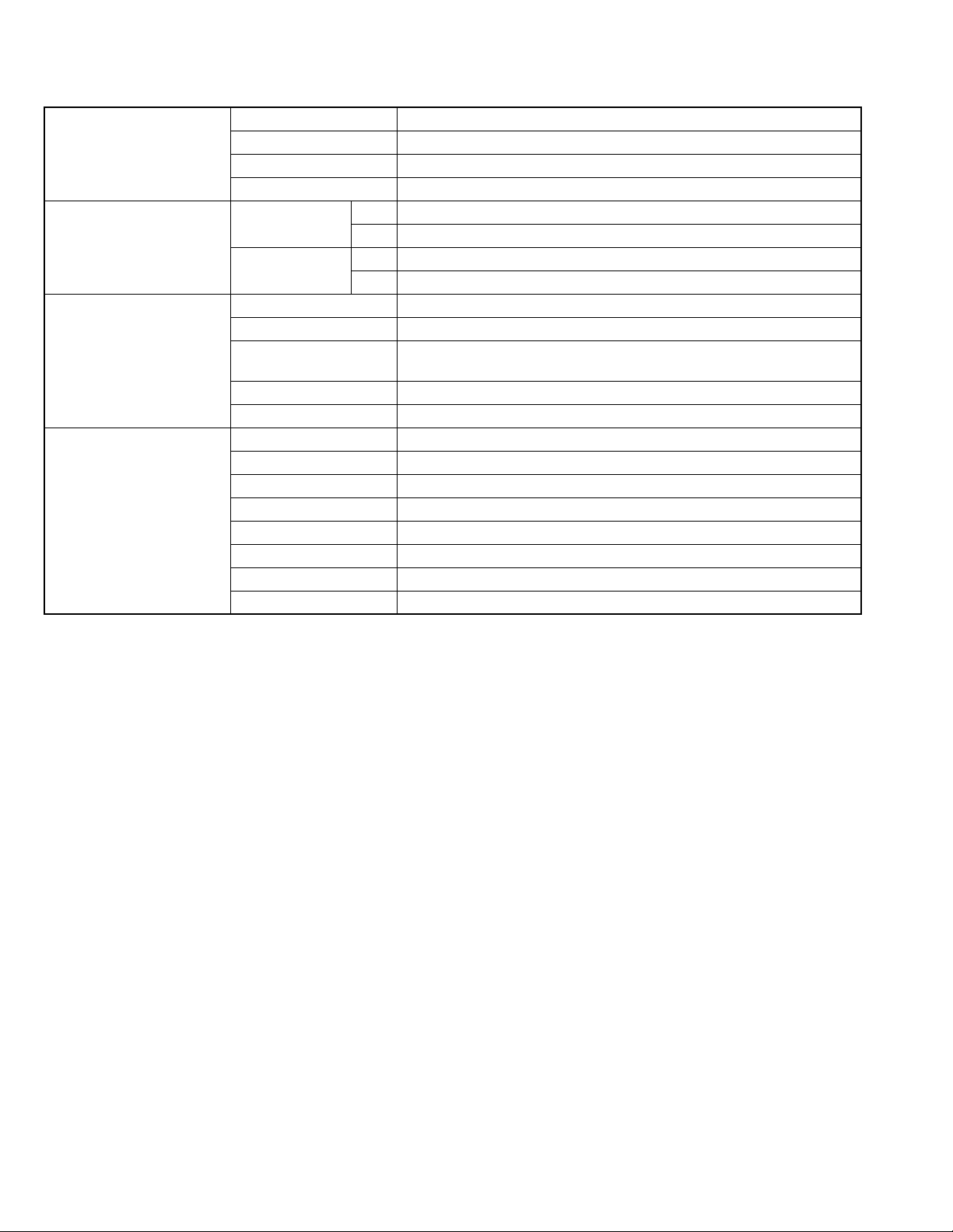
SPECIFICATION
CD player System Compact disc digital audio system
Sampling frequency 44.1 kHz
Number of channels 2 channels (Stereo)
Frequency feature 20 Hz - 20 kHz
Tuner Frequency FM 87.5 MHz - 108.0 MHz
AM 522 kHz - 1,629 kHz
Antennas FM Telescopic antenna
AM Ferrite core antenna
Cassette tape recorder Track method Compact cassette stereo
Erasing method Magnet erasing method
Head Erasing (Magnet)
Recording/playback (Hard permalloy, combination)
Winding speed Approximately 150 seconds (for a 60 minute cassette tape)
Frequency response Normal: 60 Hz - 10,000 Hz
General Clock display 24 hour display
Speakers 9 cm (round shape) × 2, 4 Ω
Output terminal Headphone (stereo mini × 1)
Output power 4W (2 W + 2 W) at 4 Ω (10% THD)
Power source AC 230 V , 50 Hz
Power consumption 15 W (during operation) 3 W (on standby)
Dimensions 420 mm (W) × 178 mm (H) × 250 mm (D)
Weight Approximately 3.4 kg (without batteries)
Design and specifications are subject to change without notice.
1-2 (No.MB324)
Page 3

SECTION 1
PRECAUTION
This service manual does not describe PRECAUTION.
SECTION 2
SPECIFIC SERVICE INSTRUCTIONS
This service manual does not describe SPECIFIC SERVICE INSTRUCTIONS.
(No.MB324)1-3
Page 4
SECTION 3
A
DISASSEMBLY
3.1 Main body
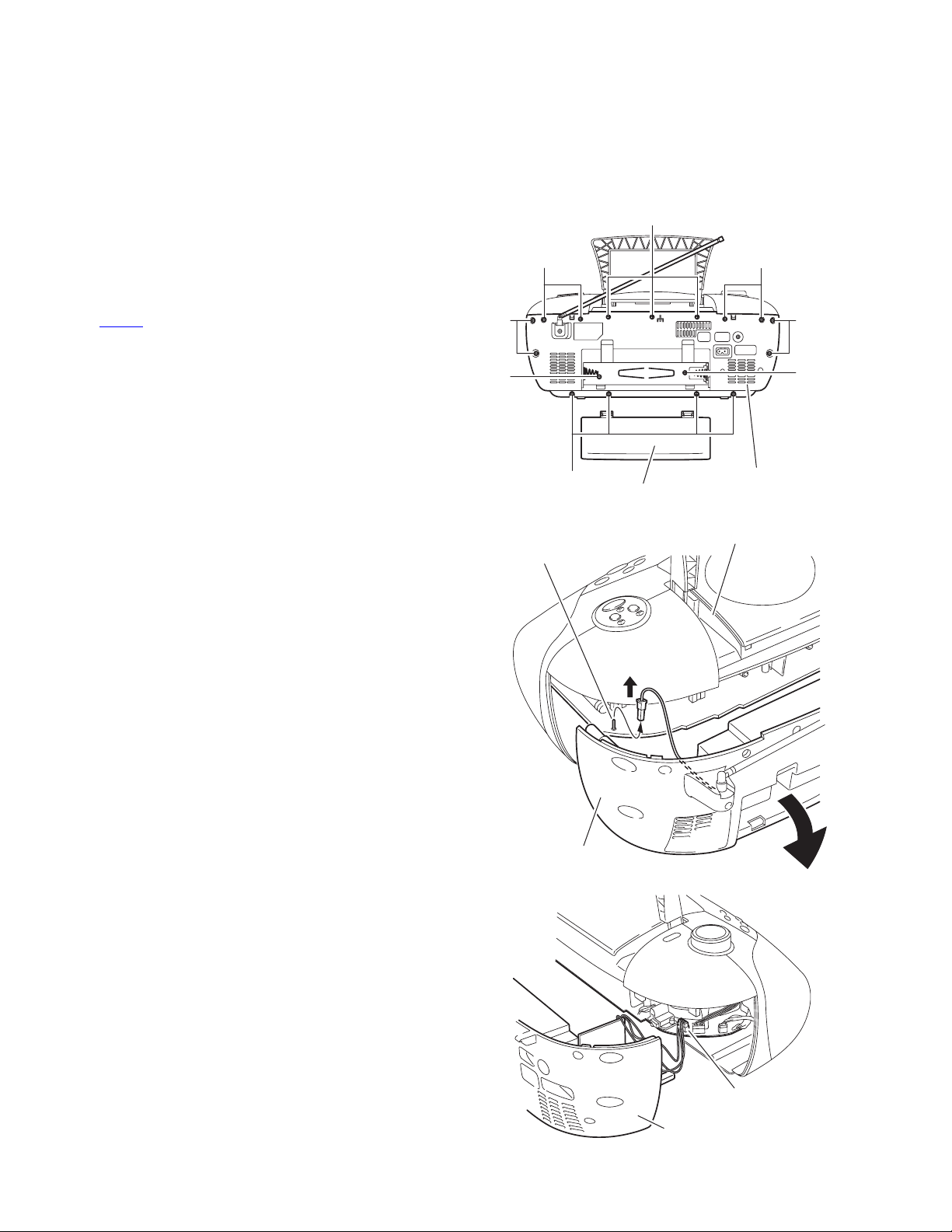
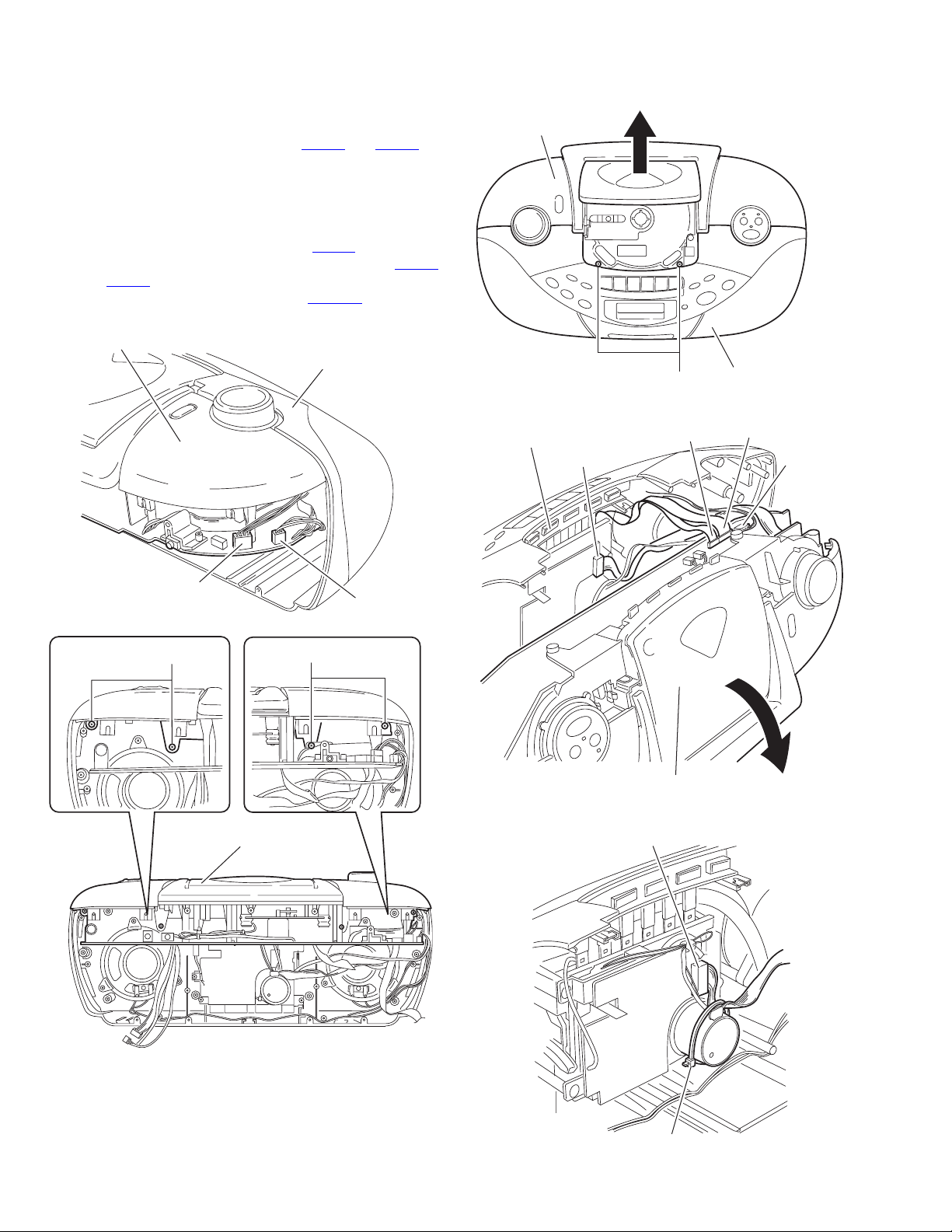
3.1.1 Removing the rear cover assembly section
(See Fig.1 ~ 3)
(1) Remove the eight screws A, the three screws B and the
four screws D attaching the rear cover assembly on the
back of the body.
(2) Remove the battery cover on the back of the body and re-
move the two screws E attaching the rear cover assembly.
(3) Move the rear cover assembly in the direction of the arrow
and remove. At this time, disconnect the wire from connector CN404
and FM-ANT on the main board.
B
DD
A
E
FM-ANT
A
E
Rear cover assembly
Battery cover
Fig.1
Top cover assembly
Rear cover assembly
Fig.2
Main board
CN404
Rear cover assembly
Fig.3
1-4 (No.MB324)
Page 5
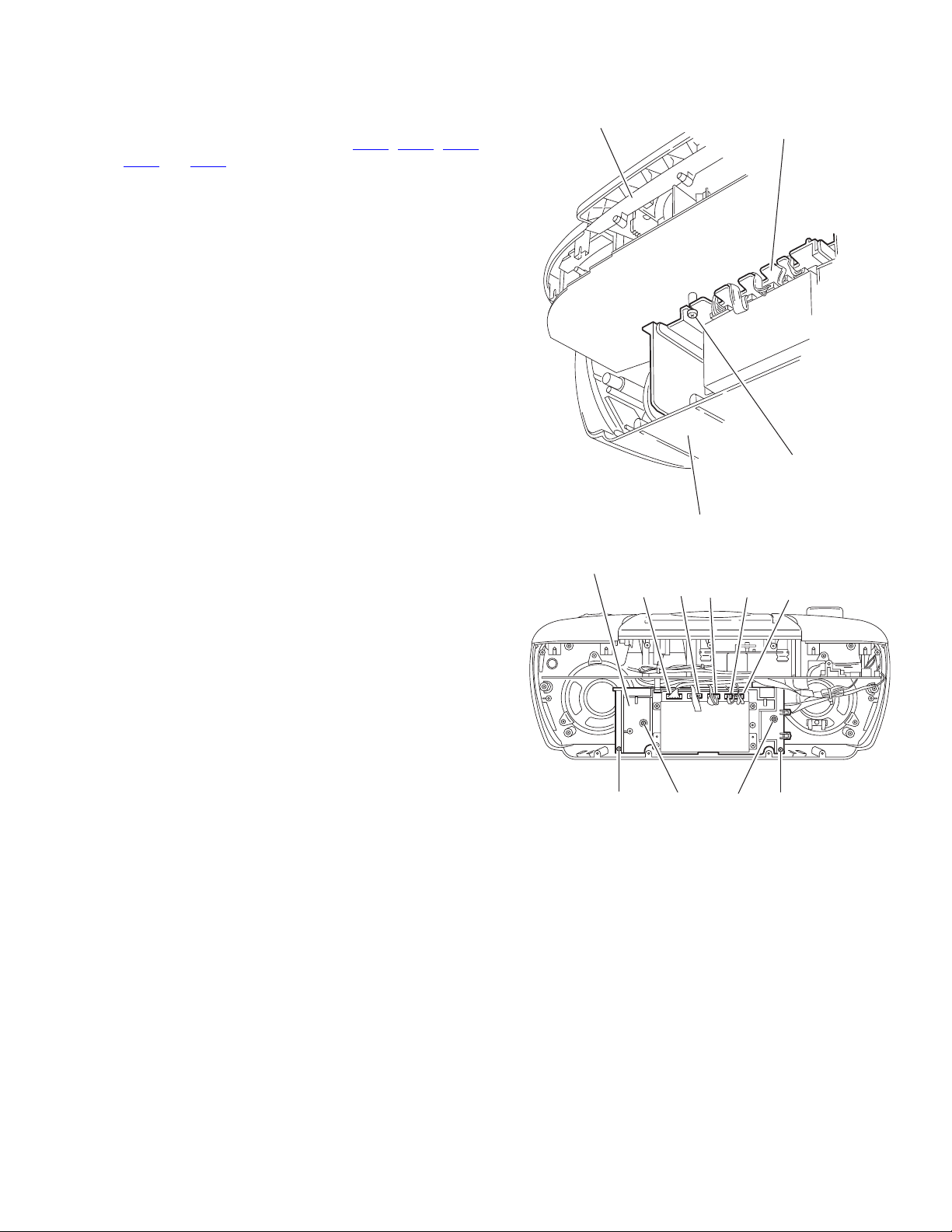
3.1.2 Removing the cassette mechanism cover
r
(See Fig.4,5)
• Prior to performing the following procedure, remove the rear
cover assembly.
(1) Disconnect the wire from connector CN11
and CN15 on the DSP board respectively.
CN14
(2) Remove the five screws F attaching the cassette mecha-
nism cover. The DSP module section comes off together
with the cassette mechanism cover.
Reference:
• you can detach the DSP module section only. See Fig.29
and Fig.30.
• Detach the cassette mechanism cover before removing the
top cover assembly section and the front panel assembly
section.
, CN12, CN13,
Top cover assembly
Front panel assembly
Cassette mechanism cover
CN14
CN15
Cassette mechanism cove
F
Fig.4
CN13
DSP board
CN11
CN12
F
F
Fig.5
F
F
(No.MB324)1-5
Page 6
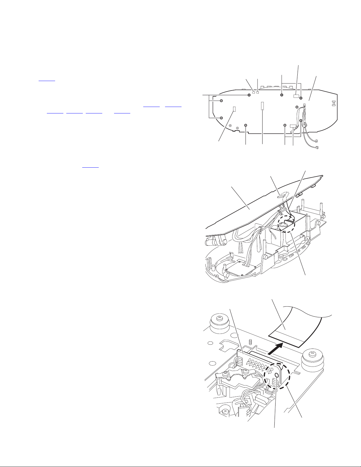
3.1.3 Removing the top cover assembly section and the front panel assembly section
(See Fig.6 ~ 10)
• Prior to performing the following procedure, remove the rear
cover assembly and cassette mechanism cover.
(1) Disconnect the wire from connector CN406 and CN407 on
the main board.
(2) Remove the four screws G and the two screws H attaching
the top cover assembly.
(3) Draw out the top cover assembly from the front panel as-
sembly section backward.
(4) Disconnect the wire from connector CN106
board, and disconnect the card wire from connector CN108
and CN109.
(5) Disconnect the wire from connector CON301 on the cas-
sette mechanism board. Remove the band from the wire.
Top cover assembly
Front panel assembly
on the main
Top cover assembly
Front panel assembly
CON301
Fig.8
Front panel assembly
H
CN109
CN108
CN106
Main board
CN407
Fig.6
GG
Top cover assembly
CN406
Top cover assembly
Fig.9
Cassette mechanism board
CON301
1-6 (No.MB324)
Fig.7
Band
Fig.10
Page 7
3.1.4 Top cover assembly section
• Prior to performing the following procedure, remove the rear cover assembly and the front panel assembly.
3.1.4.1 Removing the main body
(See Fig.11~13)
Caution:
Make sure to solder the short-circuit point on the CD servo
board before disconnecting the card wire from connector
on the main board and from the CD servo board. If you
CN703
don’t observe this instruction, the pickup may be damaged.
(1) Remove the eight screws J attaching the main board on
the top cover assembly.
(2) Disconnect the wire from connector CN101
CN103, CN107, CN703 and CN704 on the main board.
(3) Move the main board as shown in the Fig.12. Solder the
short-circuit point on the CD pickup board and disconnect
the wire extending from the main board to the CD pickup
board.
(4) If necessary, cut the band.
Caution:
When reattaching the main board, make sure to connect the
card wire from the CN703
board, and unsolder the short-circuit point.
on the main board to the CD pickup
, CN102,
CN103
CN101
J
CN107
Main board
CN703
J
Fig.11
J
J
CN703
CN102
Main board
CN704
Card wire
CD servo board
Short-circuit point
Fig.12
Card wire
Short-circuit point
Unsolder
Fig.13
(No.MB324)1-7
Page 8
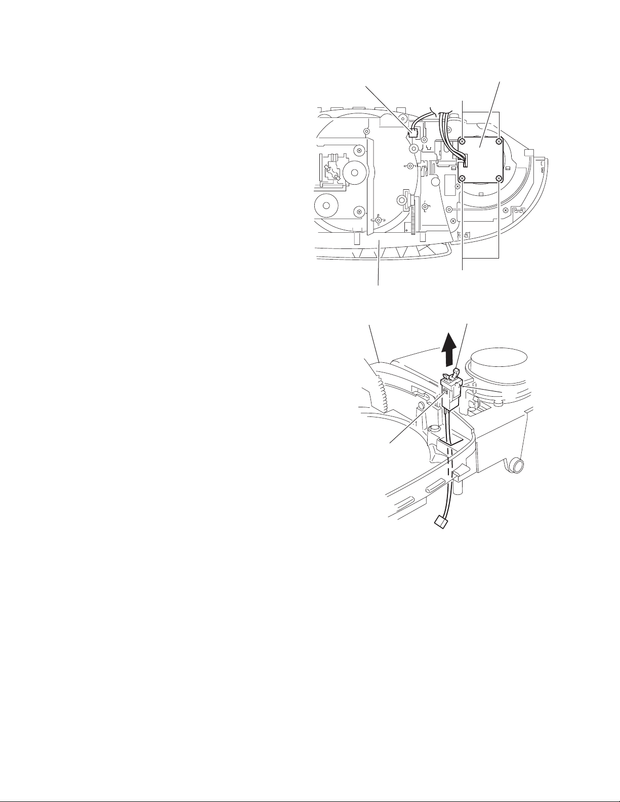
3.1.4.2 Removing the top switch board and door switch
(See Fig.14,15)
• Prior to performing the following procedure, remove the main
board.
(1) Remove the four screws K attaching the top switch board.
(2) Push two tabs a of the door switch inward and remove the
door switch toward the front side of the top cover assembly.
Door switch
Top switch board
K
Top cover assembly
Top cover assembly
a
K
Fig.14
Door switch
a
Fig.15
1-8 (No.MB324)
Page 9

3.1.4.3 Removing the volume board and the power switch board
(See Fig.16 ~ 19)
• Prior to performing the following procedure, remove the main
board.
(1) Pull out the volume knob on the front side of the top cover
assembly.
(2) Remove the three screws L attaching the volume board.
(3) Remove the four screws M attaching the side top cover on
the left side.
(4) Release the three tabs b of the side top cover on the left
side.
(5) Remove the three screws N attaching the power switch
board.
Volume knob
Top cover assembly
Side top cover
b
M
Power switch board
Fig.18
N
Volume board
Volume board
N
L
CON702
L
Fig.16
Side top cover
Power switch board
Fig.19
L
L
CON702
Fig.17
(No.MB324)1-9
Page 10

3.1.4.4 Removing the CD mechanism assembly
(See Fig.20)
• Prior to performing the following procedure, remove the main
board.
(1) Remove the four screws P attaching the CD mechanism
assembly.
P
CD mechanism assembly
Top cover assembly
P
Fig.20
1-10 (No.MB324)
Page 11

3.1.5 Front panel assembly section
• Prior to performing the following procedure, remove the rear cover assembly, the top cover assembly and the cassette mechanism
cover.
3.1.5.1 Removing the cassette mechanism assembly
(See Fig.21 ~ 23)
(1) Push Eject button to open the cassette door.
(2) Remove the four screws Q attaching the cassette mecha-
nism assembly.
(3) Pull out the cassette mechanism assembly in the direction
of arrow.
(4) Remove the six screws R attaching the operation board.
EJECT button
Cassette door
Fig.21
Front panel assembly
Cassette mechanism assembly
QQ
Fig.22
Button
R
Cassette mechanism assembly
Fig.23
(No.MB324)1-11
Page 12

3.1.5.2 Removing the LCD & switch board
(See Fig.24)
• Prior to performing the following procedure, remove the cas-
sette mechanism assembly.
(1) Remove the eight screws T attaching the LCD & switch
board.
3.1.5.3 Removing the speaker
(SeeFig.25,26)
(1) Remove the six screws U attaching the speaker bracket of
right and left.
(2) Peel the glue off attaching the speaker cord.
TT
LCD & switch board
Fig.24
UU
Speaker bracket (R)
Fig.25
Speaker (R)
Glue
UU
Speaker bracket
Fig.26
Speaker bracket (L)
Speaker (L)
1-12 (No.MB324)
Page 13

3.1.6 Rear cover assembly section
3.1.6.1 Removing the power transformer, power socket and the battery board
(See Fig.27, 28)
(1) Remove the two screws Y attaching the power transformer.
(2) Remove the two screws A’ attaching the power socket.
(3) Unsolder the six points d on the support board where the
battery board is soldered.
(4) Release the tab e setting the battery board and pull out the
battery board.
(5) If necessary, unsolder the solder points and cut the band.
Power socket
A'
Battery board
d
d
Power transformer
3.1.7 DSP module section
• Prior to performing the following procedure, remove the rear cover assembly.
3.1.7.1 Removing the DSP module section
(See Fig.29)
(1) Disconnect the wire from connector CN11
CN14
and CN15 on the DSP board respectively.
(2) Remove the four screws B’ attaching the DSP module.
, CN12, CN13,
Cassette mechanism cover
Y
Power transformer
Y
CN14
CN15
Fig.27
Power socket
Ta b e
Fig.28
CN13
DSP board
CN11
Support board
Battery board
CN12
DSP module
Fig.29
B'B'
(No.MB324)1-13
Page 14

3.1.7.2 Removing the DSP board
(See Fig.30 ~ 32)
• Prior to performing the following procedure, remove the DSP
module section.
(1) Unsolder the point f soldering the top and bottom covers on
the back of the DSP module section.
(2) Release the eight joints g on the side of the module and re-
move the top and bottom covers.
(3) Unsolder the three points h on the DSP board.
DPS board
Top cover
Bottom cover
Fig.30
g
gg
g
DSP board
Under cover
f
Fig.31
Solder point
g
g
Top cover
h
1-14 (No.MB324)
DSP board
Fig.32
Page 15

SECTION 4
ADJUSTMENT
This service manual does not describe ADJUSTMENT.
(No.MB324)1-15
Page 16

5.1 Block diagram
SECTION 5
TROUBLESHOOTING
TUNER
TA2149
KEY BOARD
CONTROL DSP
VOLUME
PLL
TC9257
5V43-4K76
LCD
DISPLAY
SYNC REC
MCU
1-16 (No.MB324)
REMOTE
CONTROL
KEY BOARD
REMOTE
SENSOR
CD PICKUP
CD SERVO
TA2092
TC9462F
FOR TUNER
CD RF AMP
TA2153FN
FOR TAPE
Page 17

Y
TAPE
SECTION
AN7312
C
BACK
LIGHT
TA8227
POWER AMP
SPEAKER
PHONE
R
MAIN
VOLTAGE
REGULATOR
E
SOURCE
SELECTOR
TC9422
HEARING DSP
MODULE
RECTIFIER
TC4052BP
POWER
SUPPLY
CD SUPPLY
BATTERY
(6x1.5V)
FOR MCU/CD
CD/MCU
VOLTAGE
REGULATOR
AC IN
(No.MB324)1-17
Page 18

5.2 Standard schematic diagrams
5.2.1 Main circuit
1-18 (No.MB324)
Page 19

(No.MB324)1-19
Page 20

5.2.2 CD Circuit
1-20 (No.MB324)
Page 21

(No.MB324)1-21
Page 22

5.2.3 Cassette Circuit
1-22 (No.MB324)
Page 23

(No.MB324)1-23
Page 24

5.2.4 Tuner circuit
1-24 (No.MB324)
Page 25

(No.MB324)1-25
Page 26

Victor Company of Japan, Limited
AV & MULTIMEDIA COMPANY AUDIO/VIDEO SYSTEMS CATEGORY 10-1,1chome,Ohwatari-machi,Maebashi-city,371-8543,Japan
(No.MB324)
Printed in Japan
WPC
 Loading...