

Page 1
SERVICE MANUAL
COMPACT COMPONENT SYSTEM
MB695<Rev.001>20094SERVICE MANUAL
NX-F30B, NX-F30E, NX-F30EN,
NX-F40B, NX-F40E, NX-F40EN
SP-NXF30W
CA-NXF40SP-NXF40F
CA-NXF30SP-NXF30F
COPYRIGHT © 2009 Victor Company of Japan, Limited
Lead free solder used in the board (material : Sn-Ag-Cu, melting point : 219 Centigrade)
Lead free solder used in the board (material : Sn-Cu, melting point : 230 Centigrade)
SP-NXF40F
SP-NXF30F
TABLE OF CONTENTS
1 PRECAUTION. . . . . . . . . . . . . . . . . . . . . . . . . . . . . . . . . . . . . . . . . . . . . . . . . . . . . . . . . . . . . . . . . . . . . . . . . 1-3
2 SPECIFIC SERVICE INSTRUCTIONS . . . . . . . . . . . . . . . . . . . . . . . . . . . . . . . . . . . . . . . . . . . . . . . . . . . . . . 1-6
3 DISASSEMBLY . . . . . . . . . . . . . . . . . . . . . . . . . . . . . . . . . . . . . . . . . . . . . . . . . . . . . . . . . . . . . . . . . . . . . . . 1-6
4 ADJUSTMENT . . . . . . . . . . . . . . . . . . . . . . . . . . . . . . . . . . . . . . . . . . . . . . . . . . . . . . . . . . . . . . . . . . . . . . . 1-14
5 TROUBLESHOOTING . . . . . . . . . . . . . . . . . . . . . . . . . . . . . . . . . . . . . . . . . . . . . . . . . . . . . . . . . . . . . . . . . 1-15
COPYRIGHT © 2009 Victor Company of Japan, Limited
No.MB695<Rev.001>
2009/4
Page 2
SPECIFICATION
Main unit (CA-NXF40/CA-NXF30)
Tuner
FM frequency 87.50 MHz - 108.00 MHz
Terminal (front of the main unit)
USB digital input terminal × 1
Audio output headphone terminal × 1 Impedance 16 Ω - 1 kΩ
Terminal (rear of the main unit)
Audio output speaker terminals × 1
Left/right speakers Output power 220 W (55 W × 4) at 3 Ω (1 kHz/10% THD)
Impedance 3 Ω - 16 Ω
Subwoofer Output power 180 W at 6 Ω (100 Hz/10% THD)
Impedance 6 Ω - 16 Ω
Optical digital input terminal × 1 -23 dBm to -15 dBm
Optical digital output terminal × 1 -23 dBm to -15 dBm
Component video output terminals × 1 Y 1.0 Vp-p, 75 Ω terminated
PB 0.7 Vp-p, 75 Ω terminated
PR 0.7 Vp-p, 75 Ω terminated
Composite video output terminal × 1 1.0 Vp-p, 75 Ω terminated
Audio input terminals × 1 500 mV/47 kΩ
HDMI monitor output terminal × 1
FM antenna terminal × 1
USB
Compatible with USB 2.0 Full-Speed
Compatible device USB mass storage class device
Compatible file system FAT16, FAT32
Output power DC 5 V = 500 mA
HDMI
Output power DC 5 V = 55 mA
General
Power source AC 230 V ~, 50 Hz
Power consumption (in operation) 100 W
Power consumption (on standby) 1 W or less
Dimensions (W × H × D) [including projecting parts] 312 mm × 95 mm × 312.3 mm
Mass 3.5 kg
Speakers (SP-NXF40F/SP-NXF30F)
Type 1-way bass reflex type
Magnetically shielded type
Speaker driver Front ch 5.5 cm cone
Surround ch 5.5 cm cone
Power handling capacity Front ch 55 W
Surround ch 55 W
Impedance 3 Ω
Frequency range 80 Hz - 20 kHz
Sound pressure level 77 dB/W/m
Dimensions (W × H × D) [including projection parts] 88 mm × 203 mm × 127 mm
Subwoofer (SP-NXF30W)
Type Bass reflex type
Speaker driver 16 cm cone
Power handling capacity 180 W
Impedance 6 Ω
Frequency range 30 Hz - 200 Hz
Sound pressure level 76 dB/W/m
Dimensions (W × H × D) 300 mm × 301 mm × 303 mm
Mass 8.2 kg
Designs and specifications are subject to change without notice.
1-2 (No.MB695<Rev.001>)
Page 3
SECTION 1
PRECAUTION
1.1 Safety Precautions
(1) This design of this product contains special hardware and
many circuits and components specially for safety purposes. For continued protection, no changes should be made
to the original design unless authorized in writing by the
manufacturer. Replacement parts must be identical to
those used in the original circuits. Services should be performed by qualified personnel only.
(2) Alterations of the design or circuitry of the product should
not be made. Any design alterations of the product should
not be made. Any design alterations or additions will void
the manufacturers warranty and will further relieve the
manufacture of responsibility for personal injury or property
damage resulting therefrom.
(3) Many electrical and mechanical parts in the products have
special safety-related characteristics. These characteristics are often not evident from visual inspection nor can the
protection afforded by them necessarily be obtained by using replacement components rated for higher voltage, wattage, etc. Replacement parts which have these special
safety characteristics are identified in the Parts List of Service Manual. Electrical components having such features
are identified by shading on the schematics and by ( ) on
the Parts List in the Service Manual. The use of a substitute
replacement which does not have the same safety characteristics as the recommended replacement parts shown in
the Parts List of Service Manual may create shock, fire, or
other hazards.
(4) The leads in the products are routed and dressed with ties,
clamps, tubings, barriers and the like to be separated from
live parts, high temperature parts, moving parts and/or
sharp edges for the prevention of electric shock and fire
hazard. When service is required, the original lead routing
and dress should be observed, and it should be confirmed
that they have been returned to normal, after reassembling.
(5) Leakage shock hazard testing
After reassembling the product, always perform an isolation check on the exposed metal parts of the product (antenna terminals, knobs, metal cabinet, screw heads,
headphone jack, control shafts, etc.) to be sure the product
is safe to operate without danger of electrical shock.Do not
use a line isolation transformer during this check.
• Plug the AC line cord directly into the AC outlet. Using a
"Leakage Current Tester", measure the leakage current
from each exposed metal parts of the cabinet, particularly any exposed metal part having a return path to the
chassis, to a known good earth ground. Any leakage current must not exceed 0.5mA AC (r.m.s.).
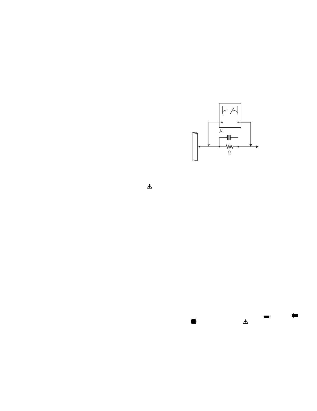
• Alternate check method
Plug the AC line cord directly into the AC outlet. Use an
AC voltmeter having, 1,000Ω per volt or more sensitivity
in the following manner. Connect a 1,500Ω 10W resistor
paralleled by a 0.15µF AC-type capacitor between an ex-
posed metal part and a known good earth ground.
Measure the AC voltage across the resistor with the AC
voltmeter.
Move the resistor connection to each exposed metal
part, particularly any exposed metal part having a return
path to the chassis, and measure the AC voltage across
the resistor. Now, reverse the plug in the AC outlet and
repeat each measurement. Voltage measured any must
not exceed 0.75 V AC (r.m.s.). This corresponds to 0.5
mA AC (r.m.s.).
AC VOLTMETER
(Having 1000
ohms/volts,
or more sensitivity)
0.15 F AC TYPE
Place this
probe on
1500 10W
Good earth ground
1.2 Warning
(1) This equipment has been designed and manufactured to
meet international safety standards.
(2) It is the legal responsibility of the repairer to ensure that
these safety standards are maintained.
(3) Repairs must be made in accordance with the relevant
safety standards.
(4) It is essential that safety critical components are replaced
by approved parts.
(5) If mains voltage selector is provided, check setting for local
voltage.
1.3 Caution
Burrs formed during molding may be left over on some parts
of the chassis.
Therefore, pay attention to such burrs in the case of preforming repair of this system.
1.4 Critical parts for safety
In regard with component parts appearing on the silk-screen
printed side (parts side) of the PWB diagrams, the parts that are
printed over with black such as the resistor ( ), diode ( )
and ICP ( ) or identified by the " " mark nearby are critical
for safety. When replacing them, be sure to use the parts of the
same type and rating as specified by the manufacturer.
(This regulation dose not Except the J and C version)
each exposed
metal part.
(No.MB695<Rev.001>)1-3
Page 4
1.5 Preventing static electricity
Electrostatic discharge (ESD), which occurs when static electricity stored in the body, fabric, etc. is discharged, can destroy the laser
diode in the traverse unit (optical pickup). Take care to prevent this when performing repairs.
1.5.1 Grounding to prevent damage by static electricity
Static electricity in the work area can destroy the optical pickup (laser diode) in devices such as laser products.
Be careful to use proper grounding in the area where repairs are being performed.
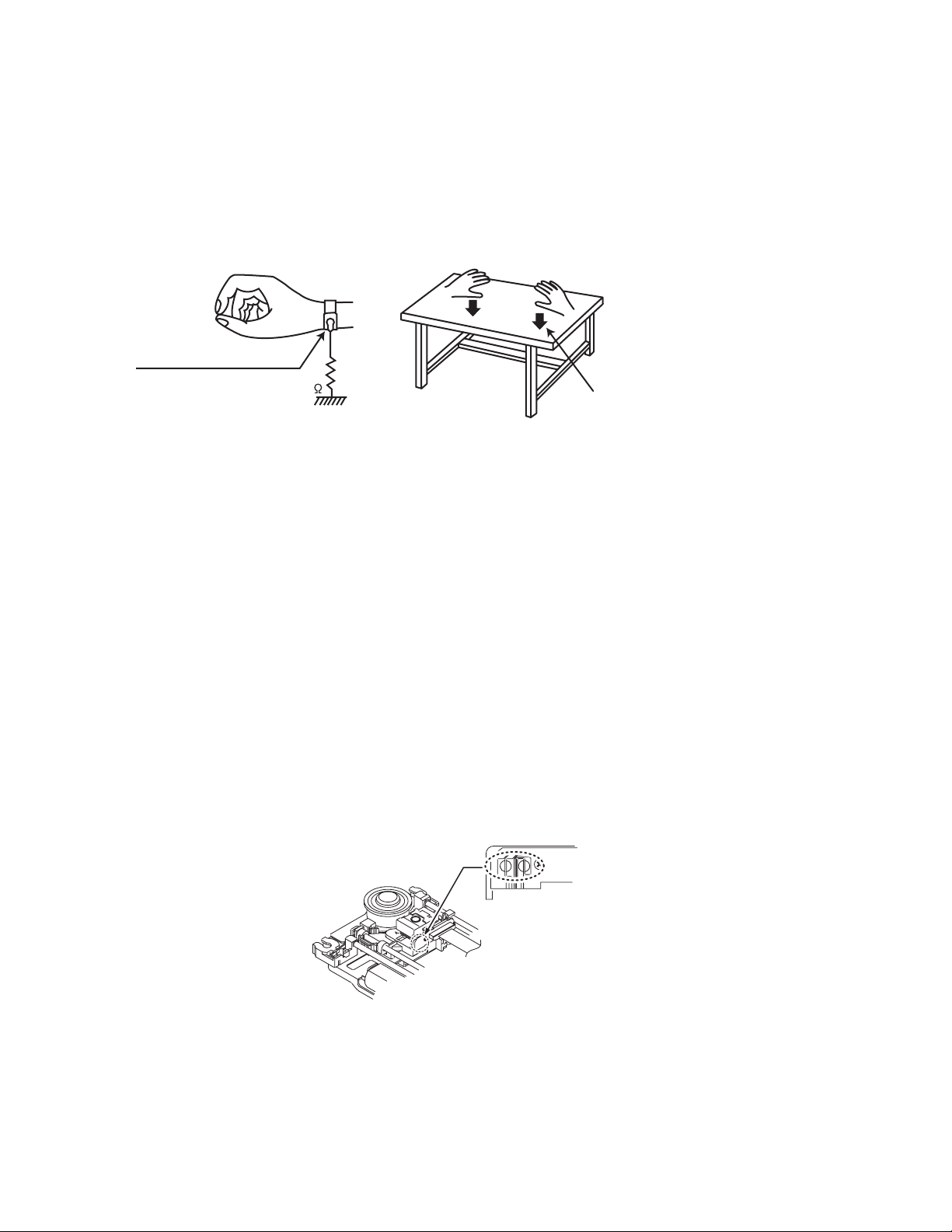
(1) Ground the workbench
Ground the workbench by laying conductive material (such as a conductive sheet) or an iron plate over it before placing the
traverse unit (optical pickup) on it.
(2) Ground yourself
Use an anti-static wrist strap to release any static electricity built up in your body.
(caption)
Anti-static wrist strap
1M
Conductive material
(conductive sheet) or iron palate
(3) Handling the optical pickup
• In order to maintain quality during transport and before installation, both sides of the laser diode on the replacement optical
pickup are shorted. After replacement, return the shorted parts to their original condition.
(Refer to the text.)
• Do not use a tester to check the condition of the laser diode in the optical pickup. The tester's internal power source can easily
destroy the laser diode.
1.6 Handling the traverse unit (optical pickup)
(1) Do not subject the traverse unit (optical pickup) to strong shocks, as it is a sensitive, complex unit.
(2) Cut off the shorted part of the flexible cable using nippers, etc. after replacing the optical pickup. For specific details, refer to the
replacement procedure in the text. Remove the anti-static pin when replacing the traverse unit. Be careful not to take too long a
time when attaching it to the connector.
(3) Handle the flexible cable carefully as it may break when subjected to strong force.
(4) I t is not possible to adjust the semi-fixed resistor that adjusts the laser power. Do not turn it.
1.7 Attention when traverse unit is decomposed
*Please refer to "Disassembly method" in the text for the pickup unit.
• Apply solder to the short land sections before the card wire is disconnected from the connecto on the servo board. (If the card wire
is disconnected without applying solder, the pickup may be destroyed by static electricity.)
• In the assembly, be sure to remove solder from the short land sections after connecting the card wire.
Solder short land section
1-4 (No.MB695<Rev.001>)
Page 5

1.8 Important for laser products
1.CLASS 1 LASER PRODUCT
2.CAUTION :
(For U.S.A.) Visible and/or invisible class II laser radiation
when open. Do not stare into beam.
(Others) Visible and/or invisible class 1M laser radiation
when open. Do not view directly with optical instruments.
3.CAUTION : Visible and/or invisible laser radiation when
open and inter lock failed or defeated. Avoid direct
exposure to beam.
4.CAUTION : This laser product uses visible and/or invisible
laser radiation and is equipped with safety switches which
prevent emission of radiation when the drawer is open and
the safety interlocks have failed or are defeated. It is
dangerous to defeat the safety switches.
5.CAUTION : If safety switches malfunction, the laser is able
to function.
6.CAUTION : Use of controls, adjustments or performance of
procedures other than those specified here in may result in
hazardous radiation exposure.
!
Please use enough caution not to
see the beam directly or touch it
in case of an adjustment or operation
check.
REPRODUCTION AND POSITION OF LABELS and PRINT
WARNING LABEL and PRINT
(No.MB695<Rev.001>)1-5
Page 6

SECTION 2
SPECIFIC SERVICE INSTRUCTIONS
This service manual does not describe SPECIFIC SERVICE INSTRUCTIONS.
SECTION 3
DISASSEMBLY
3.1 Main body (Used figure are NX-F30E)
hook
3.1.1 Removing the Top cover (See Fig.1 to 3)
(1) Remove the six screws A attaching the Top and Right cov-
er. (See Fig.1)
C
a
C
A
A
Fig.1
(2) Remove the Volume knob and Source knob.
(3) Remove the three screws B attaching the Right panel.
(See Fig.2)
B
Fig.2
(4) Slide to frontward and then remove the Right panel.
(5) Slide to backward and then remove the Side panel. (See
Fig.3)
Fig.3
(6) Slide to backward and then remove the Top cover.
3.1.2 Removing the Front panel (See Fig.4 to 7)
(1) Remove the three screws C attaching the Front panel.
(See Fig.4)
Fig.4
(2) Disconnect the card wire from Main board connected to
connector CN561
(3) Remove the three screws D attaching the Front panel.
(See Fig.5)
of the Front board. (See Fig.5)
D
CN561
D
1-6 (No.MB695<Rev.001>)
Fig.5
Page 7

(4) Disengage one hook a engaged bottom side of the Front
panel. (See Fig.4)
(5) Disengage two hooks b engaged both side of the Front
panel. (See Fig.6)
hook
b
Fig.6
(6) Disconnect the card wire from main board connected to
connector CN531
(7) Disconnect the card wire from Main board connected to
connector CN302 of the Front jack board. (See Fig.7)
(8) Disconnect the connector wire from Main boards connect-
ed to connector CN301 of the DVD module board. (See
Fig.7)
of the Touch sensor board. (See Fig.7)
CN301
(4) Remove the nine screws E attaching the Top chassis. (see
Fig.9)
E
Fig.9
(5) Remove the four screws F attaching the both side of the
Top chassis. (See Fig.10)
F
Fig.10
3.1.4 Removing the Amp board (See Fig.11)
(1) Remove the three screws G attaching the Heat sink.
(2) Remove the four screws H attaching the Amp board.
CN531 CN302
Fig.7
3.1.3 Removing the Top chassis (See Fig.8 to 10)
(1) Disconnect the card wires from Amp board connected to
connectors CN201
Fig.8)
(2) Disconnect the connector wire from Power supply unit con-
nected to connector CN103
(3) Disconnect the connector wire from Main board connected
to connector CN104
and CN202 of the Main board. (See
of the Amp board. (See Fig.8)
of the Amp board. (See Fig.8)
CN201 CN103
CN202 CN104
Fig.8
G
H
Fig.11
(No.MB695<Rev.001>)1-7
Page 8

3.1.5 Removing the Main board (See Fig.12, 13)
(1) Disconnect the connector wire from FAN connected to con-
nector CN461
(2) Disconnect the connector wire from Power supply unit con-
nected to connector CN981
(3) Disconnect the card wires from DVD module board con-
nected to connectors, CN481, CN661 and CN701 of the
Main board. (See Fig.12)
(4) Disconnect the card wire from Tuner pack connected to
connector CN421
(5) Disconnect the card wire from Loader board connected to
connector CN451
of the Main board. (See Fig.12)
of the Main board. (See Fig.12)
of the Main board. (see Fig.12)
of the Main board. (See Fig.12)
CN461 CN661CN421
3.1.6 Removing the Rear panel (See Fig.14)
(1) Remove the four screws K and one screw L attaching the
Rear panel.
KKL
Fig.14
3.1.7 Removing the DVD mechanism (See Fig.15)
(1) Remove the three screws M attaching the DVD module
board.
(2) Remove the one screw N attaching the DVD mechanism.
MN
CN451 CN981CN701 CN481
Fig.12
(6) Remove the four screws J attaching the Main board. (see
Fig.13)
J
Fig.13
Fig.15
3.1.8 Removing the Power supply unit (see Fig.16)
(1) Remove the five screws P attaching the Power supply unit.
P
P
Fig.16
1-8 (No.MB695<Rev.001>)
Page 9

3.1.9 Removing the Front jack board (See Fig.17)
(1) Remove the three screws Q attaching the Front jack board.
Q
Fig.17
3.1.10 Removing the Front board (See Fig.18)
(1) Remove the six screws R attaching the Front board.
R
Fig.18
(No.MB695<Rev.001>)1-9
Page 10

3.2 DVD mechanism assembly
3.2.1 Removing the traverse mechanism (See Fig.1 to 6)
(1) Remove the two screws A attaching the tramecha holder
from top side of DVD mechanism assembly. (See Fig.1)
(3) Remove the four screws C attaching the CB holder and
take out it. (See Fig.3)
DVD module board
A
A
(2) Remove the two screws B attaching the DVD module
board. (See Fig.2)
Clamper base
DVD mechanism assembly
Fig.1
DVD mechanism assembly
C
C
CC
Fig.3
(4) Remove the four screws D attaching the traverse mecha-
nism. (See Fig.4)
DVD mechanism assembly
Traverse mechanism assembly
B
DVD module board
1-10 (No.MB695<Rev.001>)
DD
B
Fig.4
Fig.2
Page 11

(5) Solder the solder part of DVD pick up. (See Fig.5)
Solder short land section
Fig.5
(6) Disconnect the card wire from CN101 and CN201 on the
DVD module board. (See Fig. 6)
Caution:
• Solder the short land section on the DVD pickup before disconnecting the card wire from the connector on
the DVD pickup. If the card wire is disconnected without attaching solders, the pickup may be destroyed by
static electricity.
• When attaching the DVD pickup, be sure to remove
solders from the short land section after connecting
the card wire to the connector on the DVD pickup.
DVD module board
Spring holder
Fig.8
(3) Remove the read screw from traverse mechanism assem-
bly. (See Fig.9)
EF
CN101
CN201
Fig.6
3.2.2 Removing the pickup assembly (See Fig.7 to 11)
(1) Remove the two rod springs pressing the guide shaft. (See
Fig.7)
Middle gear
Lead screw
Fig.9
(4) Remove the bar spring pressing the shaft. (See Fig.10)
(SHAFT)
(T.TABLE)
HOOK
(BAR SPRING)
Fig.10
ROD SPRING ROD SPRING
Fig.7
(2) Remove the screw E and F attaching the spring holder.
See Fig.8)
(No.MB695<Rev.001>)1-11
Page 12

(5) Take out the pickup assembly from traverse mechanism
chassis by order. (See Fig.11)
3.2.4 Removing the spindle motor assembly (See Fig.13)
(1) Remove the three screws H attaching the spindle motor
from spindle motor board.
H
order 2
order 3
order 1
Fig.11
Caution:
When attach the tray assembly, boss of loading sub assembly should attach to guide of bottom side at tray assembly. (See Fig.15)
3.2.3 Removing the feed motor assembly (See Fig.12)
(1) Remove the one screw G attaching the feed motor assem-
bly.
(2) Remove the feed motor wires from solder part of spindle
motor board.
Solder part
Spindle motor
Fig.13
Middle gear
Lead screw
1-12 (No.MB695<Rev.001>)
G
Fig.12
Page 13

3.2.5 Removing the tray assembly (See Fig.14 & 15)
(1) Remove the two screws J attaching the clamper base.
(See Fig.14)
(2) Remove the one screw K attaching the shaft guide from
bottom side. (See Fig.14)
J
order 1
order 2
clamper base
(3) Remove the two screws L attaching the shaft guide from
top side. (See Fig.15)
Caution:
When attach the tray assembly, boss of loading sub assembly should attach to guide of bottom side at tray assembly. (See Fig.15)
L
K
Fig.15
[bottom side]
Fig.14
(No.MB695<Rev.001>)1-13
Page 14

SECTION 4
ADJUSTMENT
4.1 ATTENTION IN SERVICE OF DVD SECTION
(1) When pickup, Flash ROM, DVD module board was changed, initialize EEPROM by all means
(2) When full initialization was executed, execute learning with a DVD test disc by all means.
Test disc: VT-501, VT-502
Learning method: It is adjusted automatically by normal playback of a DVD disc.
4.2 TEST MODE
4.2.1 SYSTEM COLD SET
"STOP+POWER+0" at the time of POWER OFF with reception of 2 times, the COLD SET is done.
POWER OFF state
↓
COLD SET
↓
POWER OFF state
4.2.2 FL DISPLAY / LED/ FAN / FM PRESET
"STOP+POWER+1" at the time of POWER ON with reception, the changes is done.
POWER ON state
↓
FL full display / LED blink / FAN high speed / FM preset is installed
↓
Normality indication
4.2.3 DVD STATUS MODE
"STOP+POWER+2" at the time of POWER ON with reception, the below-mentioned indication state transition is done.
Mode is cancelled with the Any Key press.
POWER ON state
↓
(1) DVD Temp Info indication
↓
(2) EDID Information indication
↓
Normality indication
4.2.4 SYSTEM STATUS MODE
"STOP+POWER+3" at the time of POWER ON with reception, the below-mentioned indication state transition is done.
Mode is cancelled with the Any Key press.
<POWER when ON >
POWER ON state
↓
(1) Indication of ShutDown cause *
↓
(2) A/D port PWR_THERMO:AMP_THERMO:Indication of the voltage of LVL_DET
↓
(3) Indication of VOLUME Gain limiting value.
Effective Gain limiting value:The Gain limiting value due to temperature:The Gain limiting value due to sound
↓
Normality indication
* Note in use
Because from POWER ON various SAFETY detection processing start 2 seconds later, When we would like to make
ShutDown cause indicate, from POWER ON move to TEST MODE within 2 seconds.
Page 15

* Indication of ShutDown cause : AA:BB:CC
Shut Down Factor, AA : 0x00 = Reset Safety kind, BB : 0xA4 = PWR_THERMO Safety Detection level : 0 = LOW
0x02 = Remote control POWER key 0xA5 = AMP_THERMO 1 = HIGH
0x03 = Front Panel POWER key 0x77 = AMP_PRT
0x05 = SLEEP trigger 0x80 = AMP_SAFETY
0x08 = CEC POWER off 0x52 = FAN_SAFETY
0x61 = SAFETY2
0x60 = SAFETY1
4.2.5 SPK OUTPUT MEASURE MODE
"STOP+POWER+4" at the time of POWER ON due to reception, it moves to SPK output measurement mode.
“MEASURE” is indicates in FL stationary, The VOLUME ATT restriction processing with audio level detection is cancelled.
The VOLUME ATT restriction processing with audio level detection is cancelled.
Exit the mode if second time STOP+POWER+4 input.
It is mode for POWER measurement on the line.
POWER ON state
↓
SPK OUTPUT MEASURE MODE
↓
Mode coming out
4.2.6 Version indication
"STOP+POWER+10" at the time of POWER ON with reception, the below-mentioned indication state transition is done.
Mode it cancels with the Any Key.
POWER ON state
↓
(1) Indication of Syscon ROM version and its ROM Correction version
↓
(2) Indication of Model name and Hardware destination
↓
(3) The indication of BE Firm Ver
↓
(4) Indication of BE destination / REGION No
↓
Normality indication
4.2.7 DVD INITIALIZATION
Press of front panel POWER key at the time of AC plug IN, enter the DVD test mode.
Press and hold POWER key + AC IN
↓
(1) "T ##$ 0 "
↓
(2) Press PLAY key on front panel, "T ##$ 00"
↓
DVD initialization end
This service manual does not describe TROUBLESHOOTING.
SECTION 5
TROUBLESHOOTING
(No.MB695<Rev.001>)1-15
Page 16

Victor Company of Japan, Limited
Audio/Video Systems Division 10-1,1chome,Ohwatari-machi,Maebashi-city,371-8543,Japan
(No.MB695<Rev.001>)
Printed in Japan
VSE
 Loading...