

Page 1
SERVICE MANUAL
MB726<Rev.001>20102SERVICE MANUAL
NX-D4B,NX-D4E,NX-D4A
COMPACT COMPONENT SYSTEM
SP-NXD3SP-NXD3 CA-NXD4
except NX-D4A
COPYRIGHT © 2010 Victor Company of Japan, Limited
Lead free solder used in the board (material : Sn-Ag-Cu, melting point : 219 Centigrade)
Lead free solder used in the board (material : Sn-Cu, melting point : 230 Centigrade)
TABLE OF CONTENTS
1 PRECAUTION. . . . . . . . . . . . . . . . . . . . . . . . . . . . . . . . . . . . . . . . . . . . . . . . . . . . . . . . . . . . . . . . . . . . . . . . . 1-4
2 SPECIFIC SERVICE INSTRUCTIONS . . . . . . . . . . . . . . . . . . . . . . . . . . . . . . . . . . . . . . . . . . . . . . . . . . . . . . 1-7
3 DISASSEMBLY . . . . . . . . . . . . . . . . . . . . . . . . . . . . . . . . . . . . . . . . . . . . . . . . . . . . . . . . . . . . . . . . . . . . . . . 1-7
4 ADJUSTMENT . . . . . . . . . . . . . . . . . . . . . . . . . . . . . . . . . . . . . . . . . . . . . . . . . . . . . . . . . . . . . . . . . . . . . . . 1-16
5 TROUBLESHOOTING . . . . . . . . . . . . . . . . . . . . . . . . . . . . . . . . . . . . . . . . . . . . . . . . . . . . . . . . . . . . . . . . . 1-17
COPYRIGHT © 2010 Victor Company of Japan, Limited
No.MB726<Rev.001>
2010/2
Page 2

SPECIFICATION
NX-D4 for Europe
Amplifier section
Output Power 230 W (115 W + 115 W) at 3 Ω (10% THD)
Audio Input AUDIO IN Stereo mini ( Ø 3.5 mm)
500 mV/47 kΩ (at “AUDIO LVL3”)
250 mV/47 kΩ (at “AUDIO LVL2”)
125 mV/47 kΩ (at “AUDIO LVL1”)
Digital Input/Output
USB REC/PLAY (input and output)
VIDEO OUT Color system PAL/NTSC (interlaced/progressive)
Speaker impedance 3 Ω - 16 Ω
Tuner section
FM tuning range 87.50 MHz - 108.00 MHz
AM (MW) tuning range 522 kHz - 1 629 kHz
Disc player section
Dynamic range 80 dB
Horizontal resolution 500 lines
Wow and flutter Immeasurable
iPod section
Power supply DC 5 V 500 mA (each iPod dock)
USB section
USB specification Compatible with USB 2.0 Full Speed
Compatible device Mass storage class
Compatible system FAT16, FAT32
Output power DC 5 V 500 mA
General
Power requirements AC 230 V , 50 Hz
Power consumption 90 W (at operation)
Dimensions (approx.) 195 mm × 333 mm × 313 mm (W × H × D)
Mass (approx.) 3.6 kg
System Speaker-SP-NXD3
Type 3-way 3-speaker Bass Reflex Type (Magnetically-Shielded Type)
Speaker units Tweeter 2.0 cm cone × 1
Impedance 3 Ω
Power handling capacity 115 W
Frequency range 40 Hz - 20 000 Hz
Sound pressure level 84 dB/W
Dimensions 205 mm × 409.5 mm × 290.5 mm (W × H × D)
Mass 3.6 kg each
OPTICAL DIGITAL OUTPUT (output only)
VIDEO (Composite) 1 V(p-p)/75 Ω
COMPONENT (Y) 1 V(p-p)/75 Ω
Mid Range 5.0 cm cone × 1
Woofer 16.0 cm cone × 1
-21 dBm to -15 dBm (660 nm ± 30 nm)
(PB/PR) 0.7 V(p-p)/75 Ω
1.00 W or less (at standby)
·m
1-2 (No.MB726<Rev.001>)
Page 3

NX-D4 for A
Amplifier section
Output Power 230 W (115 W + 115 W) at 3 Ω (10% THD)
Audio Input AUDIO IN Stereo mini ( Ø 3.5 mm)
500 mV/47 kΩ (at “AUDIO LVL3”)
250 mV/47 kΩ (at “AUDIO LVL2”)
125 mV/47 kΩ (at “AUDIO LVL1”)
Digital Input/Output
USB REC/PLAY (input and output)
VIDEO OUT Color system PAL/NTSC (interlaced/progressive)
Speaker impedance 3 Ω - 16 Ω
Tuner section
FM tuning range 87.50 MHz - 108.00 MHz
AM (MW) tuning range 522 kHz - 1 629 kHz
Disc player section
Dynamic range 80 dB
Horizontal resolution 500 lines
Wow and flutter Immeasurable
iPod section
Power supply DC 5 V 500 mA (each iPod dock)
USB section
USB specification Compatible with USB 2.0 Full Speed
Compatible device Mass storage class
Compatible system FAT16, FAT32
Output power DC 5 V 500 mA
General
Power requirements AC 240 V , 50 Hz
Power consumption 90 W (at operation)
Dimensions (approx.) 195 mm × 333 mm × 313 mm (W × H × D)
Mass (approx.) 3.6 kg
System Speaker-SP-NXD3
Type 3-way 3-speaker Bass Reflex Type (Magnetically-Shielded Type)
Speaker units Tweeter 2.0 cm cone × 1
Impedance 3 Ω
Power handling capacity 115 W
Frequency range 40 Hz - 20 000 Hz
Sound pressure level 84 dB/W
Dimensions 205 mm × 409.5 mm × 290.5 mm (W × H × D)
Mass 3.6 kg each
OPTICAL DIGITAL OUTPUT (output only)
VIDEO (Composite) 1 V(p-p)/75 Ω
COMPONENT (Y) 1 V(p-p)/75 Ω
Mid Range 5.0 cm cone × 1
Woofer 16.0 cm cone × 1
-21 dBm to -15 dBm (660 nm ± 30 nm)
(PB/PR) 0.7 V(p-p)/75 Ω
16 W or less (at standby)
1 W or less (at ECO mode)
·m
(No.MB726<Rev.001>)1-3
Page 4
SECTION 1
PRECAUTION
1.1 Safety Precautions
(1) This design of this product contains special hardware and
many circuits and components specially for safety purposes. For continued protection, no changes should be made
to the original design unless authorized in writing by the
manufacturer. Replacement parts must be identical to
those used in the original circuits. Services should be performed by qualified personnel only.
(2) Alterations of the design or circuitry of the product should
not be made. Any design alterations of the product should
not be made. Any design alterations or additions will void
the manufacturers warranty and will further relieve the
manufacture of responsibility for personal injury or property
damage resulting therefrom.
(3) Many electrical and mechanical parts in the products have
special safety-related characteristics. These characteristics are often not evident from visual inspection nor can the
protection afforded by them necessarily be obtained by using replacement components rated for higher voltage, wattage, etc. Replacement parts which have these special
safety characteristics are identified in the Parts List of Service Manual. Electrical components having such features
are identified by shading on the schematics and by ( ) on
the Parts List in the Service Manual. The use of a substitute
replacement which does not have the same safety characteristics as the recommended replacement parts shown in
the Parts List of Service Manual may create shock, fire, or
other hazards.
(4) The leads in the products are routed and dressed with ties,
clamps, tubings, barriers and the like to be separated from
live parts, high temperature parts, moving parts and/or
sharp edges for the prevention of electric shock and fire
hazard. When service is required, the original lead routing
and dress should be observed, and it should be confirmed
that they have been returned to normal, after reassembling.
(5) Leakage shock hazard testing
After reassembling the product, always perform an isolation check on the exposed metal parts of the product (antenna terminals, knobs, metal cabinet, screw heads,
headphone jack, control shafts, etc.) to be sure the product
is safe to operate without danger of electrical shock.Do not
use a line isolation transformer during this check.
• Plug the AC line cord directly into the AC outlet. Using a
"Leakage Current Tester", measure the leakage current
from each exposed metal parts of the cabinet, particularly any exposed metal part having a return path to the
chassis, to a known good earth ground. Any leakage current must not exceed 0.5mA AC (r.m.s.).
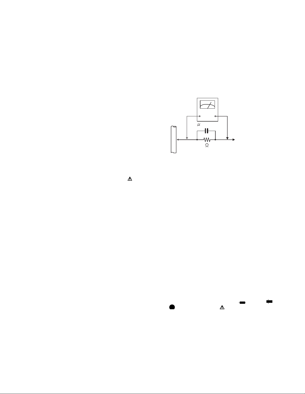
• Alternate check method
Plug the AC line cord directly into the AC outlet. Use an
AC voltmeter having, 1,000Ω per volt or more sensitivity
in the following manner. Connect a 1,500Ω 10W resistor
paralleled by a 0.15µF AC-type capacitor between an ex-
posed metal part and a known good earth ground.
Measure the AC voltage across the resistor with the AC
voltmeter.
Move the resistor connection to each exposed metal
part, particularly any exposed metal part having a return
path to the chassis, and measure the AC voltage across
the resistor. Now, reverse the plug in the AC outlet and
repeat each measurement. Voltage measured any must
not exceed 0.75 V AC (r.m.s.). This corresponds to 0.5
mA AC (r.m.s.).
AC VOLTMETER
(Having 1000
ohms/volts,
or more sensitivity)
0.15 F AC TYPE
Place this
probe on
1500 10W
Good earth ground
1.2 Warning
(1) This equipment has been designed and manufactured to
meet international safety standards.
(2) It is the legal responsibility of the repairer to ensure that
these safety standards are maintained.
(3) Repairs must be made in accordance with the relevant
safety standards.
(4) It is essential that safety critical components are replaced
by approved parts.
(5) If mains voltage selector is provided, check setting for local
voltage.
1.3 Caution
Burrs formed during molding may be left over on some parts
of the chassis.
Therefore, pay attention to such burrs in the case of preforming repair of this system.
1.4 Critical parts for safety
In regard with component parts appearing on the silk-screen
printed side (parts side) of the PWB diagrams, the parts that are
printed over with black such as the resistor ( ), diode ( )
and ICP ( ) or identified by the " " mark nearby are critical
for safety. When replacing them, be sure to use the parts of the
same type and rating as specified by the manufacturer.
(This regulation dose not Except the J and C version)
each exposed
metal part.
1-4 (No.MB726<Rev.001>)
Page 5
1.5 Preventing static electricity
Electrostatic discharge (ESD), which occurs when static electricity stored in the body, fabric, etc. is discharged, can destroy the laser
diode in the traverse unit (optical pickup). Take care to prevent this when performing repairs.
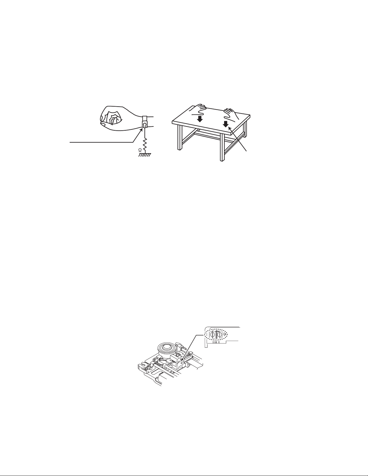
1.5.1 Grounding to prevent damage by static electricity
Static electricity in the work area can destroy the optical pickup (laser diode) in devices such as laser products.
Be careful to use proper grounding in the area where repairs are being performed.
(1) Ground the workbench
Ground the workbench by laying conductive material (such as a conductive sheet) or an iron plate over it before placing the
traverse unit (optical pickup) on it.
(2) Ground yourself
Use an anti-static wrist strap to release any static electricity built up in your body.
(caption)
Anti-static wrist strap
1M
Conductive material
(conductive sheet) or iron palate
(3) Handling the optical pickup
• In order to maintain quality during transport and before installation, both sides of the laser diode on the replacement optical
pickup are shorted. After replacement, return the shorted parts to their original condition.
(Refer to the text.)
• Do not use a tester to check the condition of the laser diode in the optical pickup. The tester's internal power source can easily
destroy the laser diode.
1.6 Handling the traverse unit (optical pickup)
(1) Do not subject the traverse unit (optical pickup) to strong shocks, as it is a sensitive, complex unit.
(2) Cut off the shorted part of the flexible cable using nippers, etc. after replacing the optical pickup. For specific details, refer to the
replacement procedure in the text. Remove the anti-static pin when replacing the traverse unit. Be careful not to take too long a
time when attaching it to the connector.
(3) Handle the flexible cable carefully as it may break when subjected to strong force.
(4) I t is not possible to adjust the semi-fixed resistor that adjusts the laser power. Do not turn it.
1.7 Attention when traverse unit is decomposed
*Please refer to "Disassembly method" in the text for the pickup unit.
• Apply solder to the short land sections before the card wire is disconnected from the connector on the servo board. (If the card wire
is disconnected without applying solder, the pickup may be destroyed by static electricity.)
• In the assembly, be sure to remove solder from the short land sections after connecting the card wire.
Solder short land section
(No.MB726<Rev.001>)1-5
Page 6
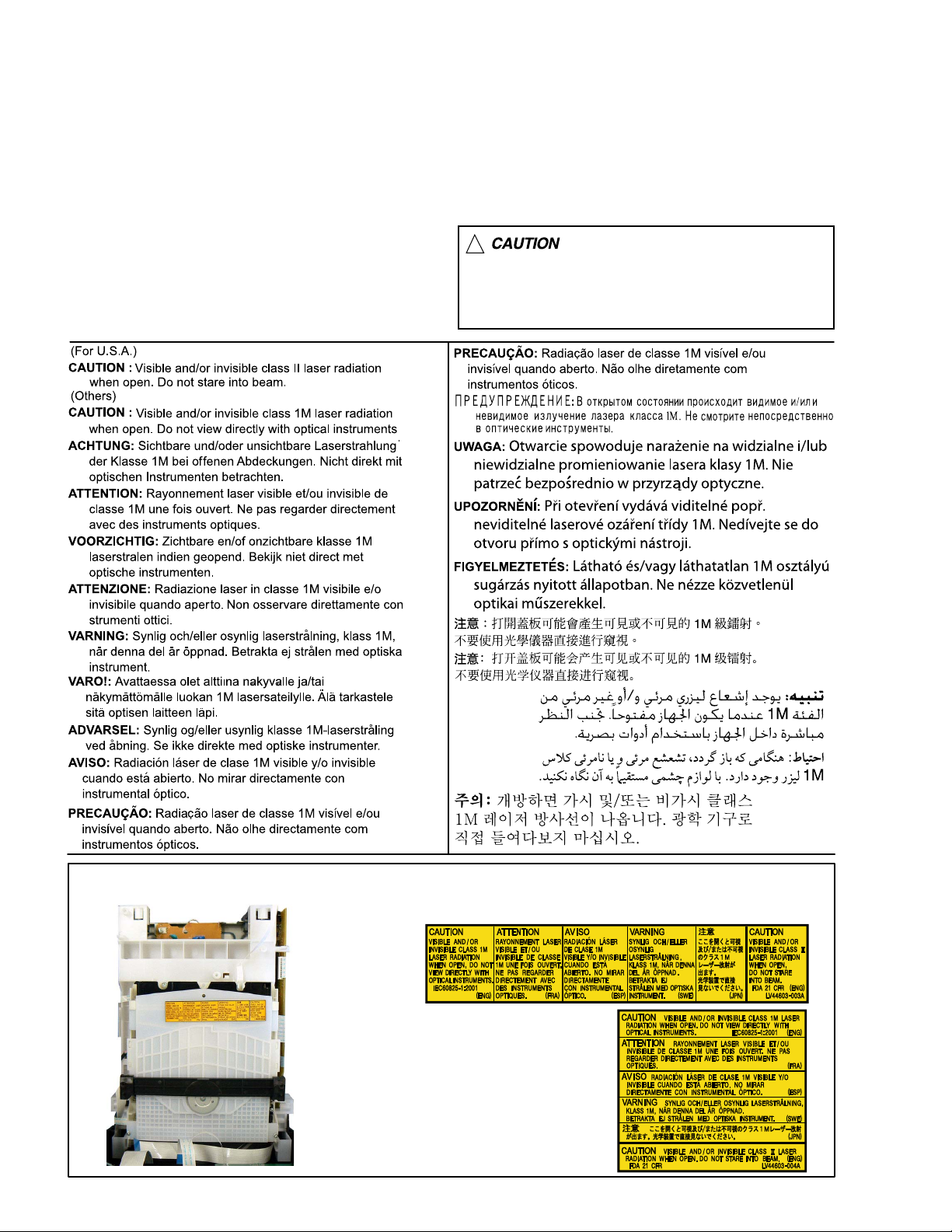
1.8 Important for laser products
1.CLASS 1 LASER PRODUCT
2.CAUTION :
(For U.S.A.) Visible and/or invisible class II laser radiation
when open. Do not stare into beam.
(Others) Visible and/or invisible class 1M laser radiation
when open. Do not view directly with optical instruments.
3.CAUTION : Visible and/or invisible laser radiation when
open and inter lock failed or defeated. Avoid direct
exposure to beam.
4.CAUTION : This laser product uses visible and/or invisible
laser radiation and is equipped with safety switches which
prevent emission of radiation when the drawer is open and
the safety interlocks have failed or are defeated. It is
dangerous to defeat the safety switches.
5.CAUTION : If safety switches malfunction, the laser is able
to function.
6.CAUTION : Use of controls, adjustments or performance of
procedures other than those specified here in may result in
hazardous radiation exposure.
!
Please use enough caution not to
see the beam directly or touch it
in case of an adjustment or operation
check.
REPRODUCTION AND POSITION OF LABELS and PRINT
WARNING LABEL and PRINT
1-6 (No.MB726<Rev.001>)
Page 7
SECTION 2
SPECIFIC SERVICE INSTRUCTIONS
This service manual does not describe SPECIFIC SERVICE INSTRUCTIONS.
SECTION 3
DISASSEMBLY
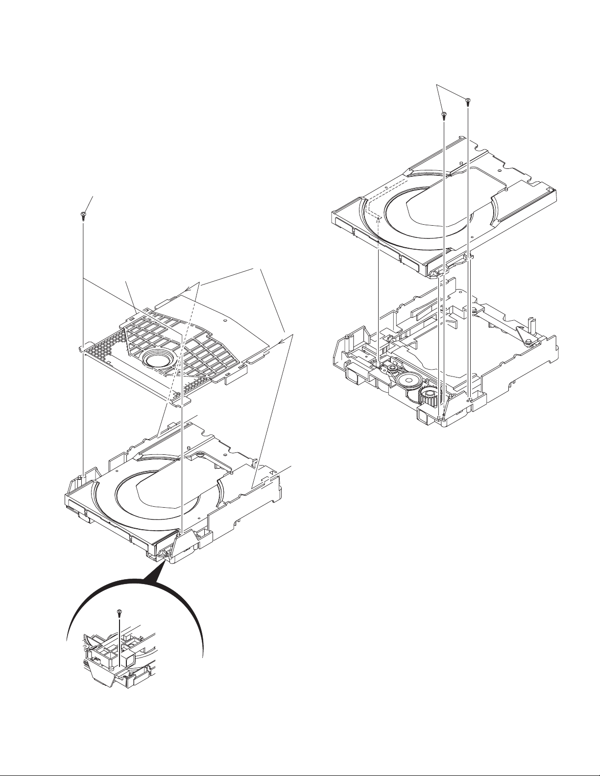
3.1 Main body (Used figure were NX-D4E)
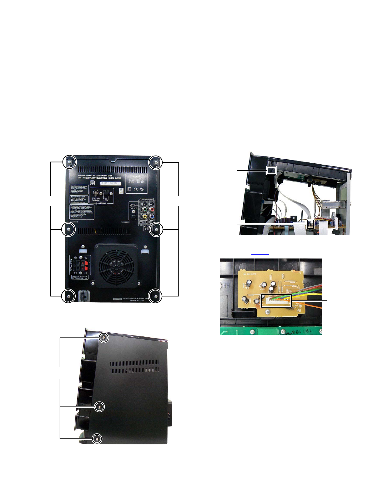
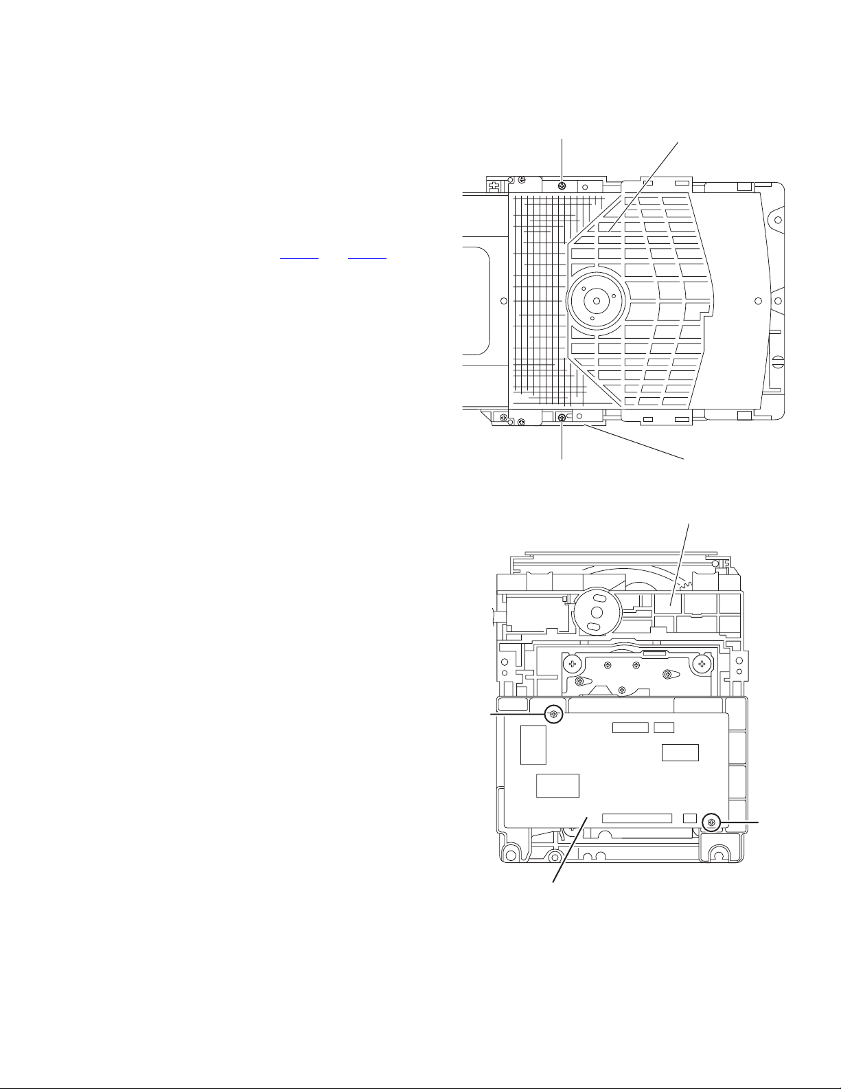
3.1.1 Removing the Top cover (See Fig.1, 2, 3, 4)
(1) Remove the six screws A attaching the both Side panel.
(See Fig.1)
AA
Fig.1
(2) Remove the six screws B attaching the both Side panel.
(See Fig.2)
(3) Disconnect the card wire from iPod board connected to
connector CN400
(4) Disengage two hooks a engaged both side of the Top cov-
er. (See Fig.3)
hook a
CN400
(5) Disconnect the connector wire from Main board connected
to connector CN401
of the Main board. (See Fig.3)
Fig.3
of the iPod switch board. (See Fig.4)
CN401
B
Fig.4
Fig.2
(No.MB726<Rev.001>)1-7
Page 8
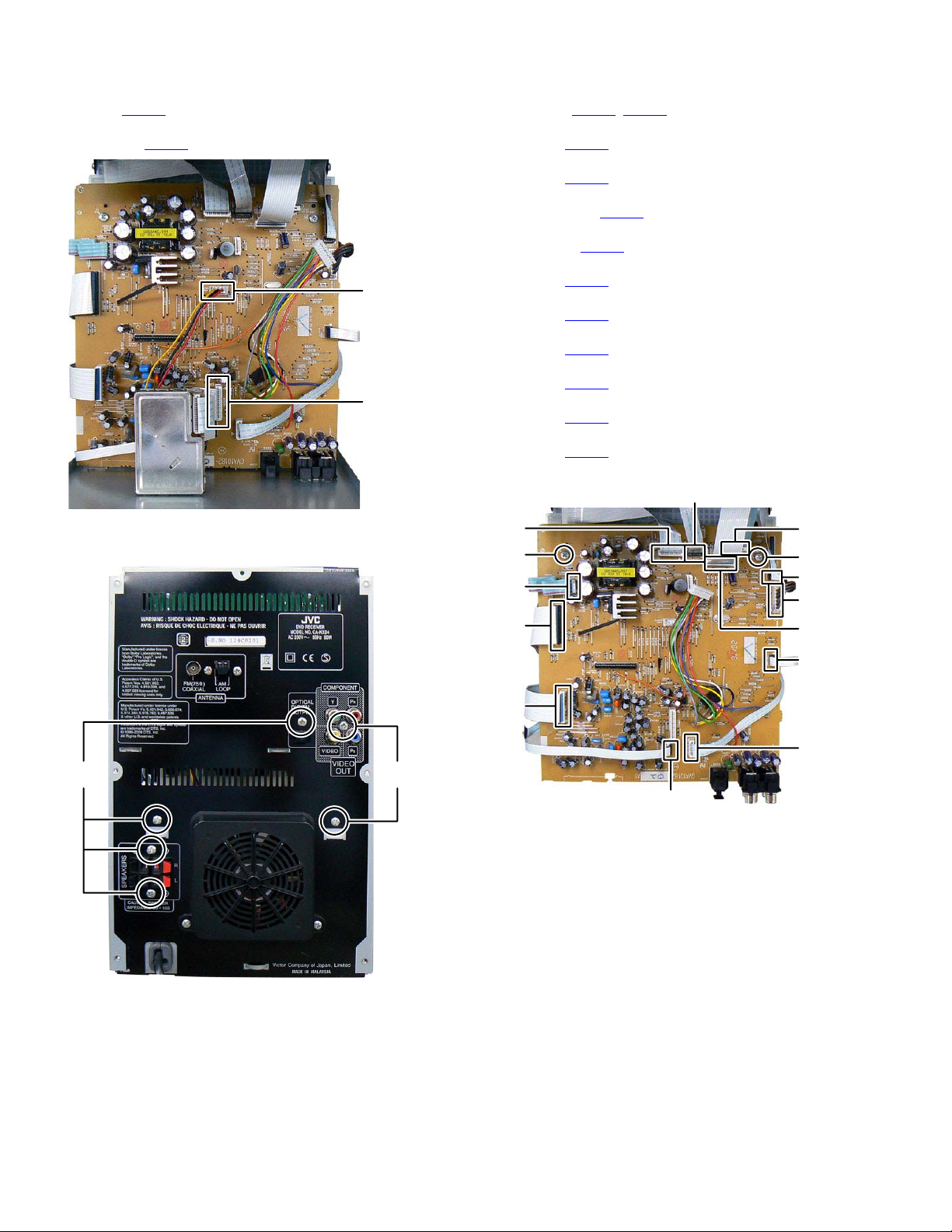
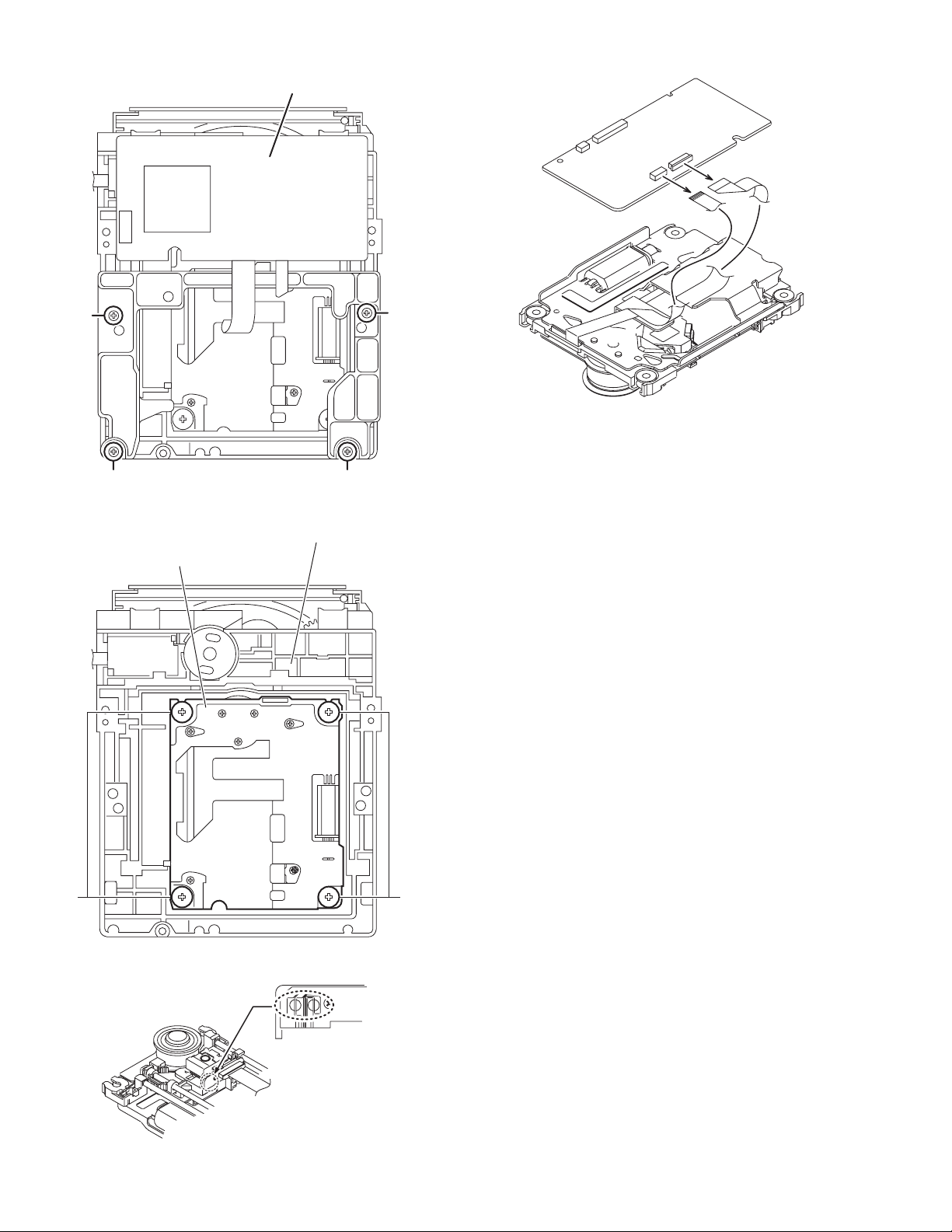
3.1.2 Removing the Rear panel (See Fig.5, 6)
(1) Disconnect the connector wire from FAN connected to con-
nector CN303
(2) Disconnect the card wire from Tuner pack connected to
connector CN306
(3) Remove the six screws C attaching the Rear panel. (See
Fig.6)
of the Main board. (See Fig.5)
of the Main board. (See Fig.5)
CN303
CN306
Fig.5
3.1.3 Removing the Main board (See Fig.7)
(1) Disconnect the card wire from Front panel connected to
connectors CN301
(2) Disconnect the parallel wire from Front panel connected to
connector CN315
(3) Disconnect the card wire from Loader board connected to
connector CN307 of the Main board.
(4) Disconnect the connector wire from Power board connect-
ed to connector CN180
(5) Disconnect the card wire from DVD mechanism connected
to connector CN309
(6) Disconnect the card wire from USB board connected to
connector CN502 of the Main board.
(7) Disconnect the card wire from DVD board connected to
connector CN500
(8) Disconnect the card wire from Amp board connected to
connector CN503
(9) Disconnect the card wire from DVD board connected to
connector CN310 of the Main board.
(10) Disconnect the parallel wire from Amp board connected to
connector CN181
(11) Disconnect the card wire from the Mic board connected to
connector CN304
(12) Remove the two screws D attaching the Main board.
CN304
D
CN181
CN310
, CN312 of the Main board.
of the Main board.
of the Main board.
of the Main board.
of the Main board.
of the Main board.
of the Main board.
of the Main board.
CN301
CN315
D
CN307
CN180
CN312
Fig.6
CN309
CN503
CN502
CC
CN500
Fig.7
1-8 (No.MB726<Rev.001>)
Page 9
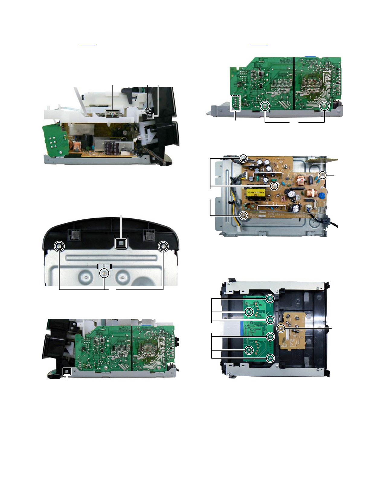
3.1.4 Removing the DVD mechanism (See Fig.8)
(1) Disconnect the connector wire from USB board connected
to connector CN811
(2) Remove the two screws E attaching the both side of the
DVD mechanism.
(3) Disengage two hooks b engaged both side of the DVD
mechanism.
of the DVD board.
3.1.6 Removing the Amp board (See Fig.11)
(1) Disconnect the connector wire from power board connect-
ed to connector CN601
(2) Remove the two screws G attaching the Amp board.
of the Amp board.
CN811
Fig.8
3.1.5 Removing the Front panel (See Fig.9, 10)
(1) Remove the three screws F attaching the Front panel. (See
Fig.9)
(2) Disengage one hook c engaged Front panel. (See Fig.9)
hook
c
E
hook
b
CN601
Fig.11
3.1.7 Removing the Power board (See Fig.12)
(1) Remove the four screws H attaching the Power board.
G
H
H
Fig.12
3.1.8 Removing the iPod board (See Fig.13)
(1) Remove the six screws J attaching the iPod board.
3.1.9 Removing the iPod switch board (See Fig.13)
(1) Remove the one screw K attaching the iPod switch board.
F
Fig.9
(3) Disengage two hooks d engaged both side of the Front
panel. (See Fig.10)
hook d
Fig.10
J
Fig.13
(No.MB726<Rev.001>)1-9
K
Page 10
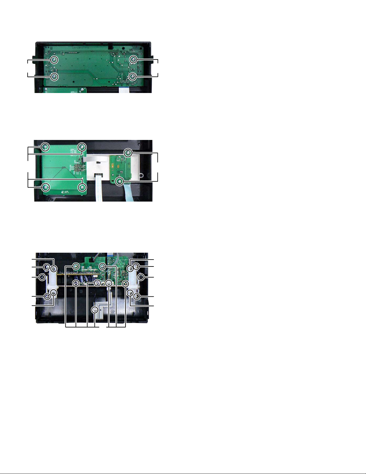
3.1.10 Removing the FL board (See Fig.14)
(1) Remove the four screws L attaching the FL board.
L
Fig.14
3.1.11 Removing the Touch sensor board (See Fig.15)
(1) Remove the four screws M attaching the Volume board.
(2) Remove the two screws N attaching the LED board.
CAUTION: The touch sensor board sticks to a Front
lens.
M
Fig.15
3.1.12 Removing the Mic board and USB board (See Fig.16)
(1) Remove the two screws P attaching the Slide door.
(2) Remove the four screws Q attaching the Slide arm.
(3) Remove the four screws R attaching the Shaft holder.
(4) Remove the seven screws S attaching the Mic board and
USB board.
L
N
R
Q
P
Q
R
R
Q
P
Q
R
S
Fig.16
1-10 (No.MB726<Rev.001>)
Page 11
3.2 DVD mechanism
3.2.1 Removing the traverse mechanism
(See Fig.1 to 6)
(1) Remove the two screws A attaching the tramecha holder
from top side of DVD mechanism assembly. (See Fig.1)
(2) Remove the two screws B attaching the DVD module
board. (See Fig.2)
(3) Remove the four screws C attaching the CB holder and
take out it. (See Fig.3)
(4) Remove the four screws D attaching the traverse mecha-
nism. (See Fig.4)
(5) Solder the solder part of DVD pick up. (See Fig.5)
(6) Disconnect the card wire from CN101
DVD module board. (See Fig. 6)
Caution:
• Solder the short land section on the DVD pickup before dis-
connecting the card wire from the connector on the DVD
pickup. If the card wire is disconnected without attaching solders, the pickup may be destroyed by static electricity.
• When attaching the DVD pickup, be sure to remove solders
from the short land section after connecting the card wire to
the connector on the DVD pickup.
and CN201 on the
A
Clamper base
B
A
DVD mechanism assembly
Fig.1
DVD mechanism assembly
B
DVD module board
Fig.2
(No.MB726<Rev.001>)1-11
Page 12
DVD module board
DVD module board
CN101
CN201
C
C
CC
Fig.3
DVD mechanism assembly
Traverse mechanism assembly
Fig.6
DD
Fig.4
Solder short land section
Fig.5
1-12 (No.MB726<Rev.001>)
Page 13
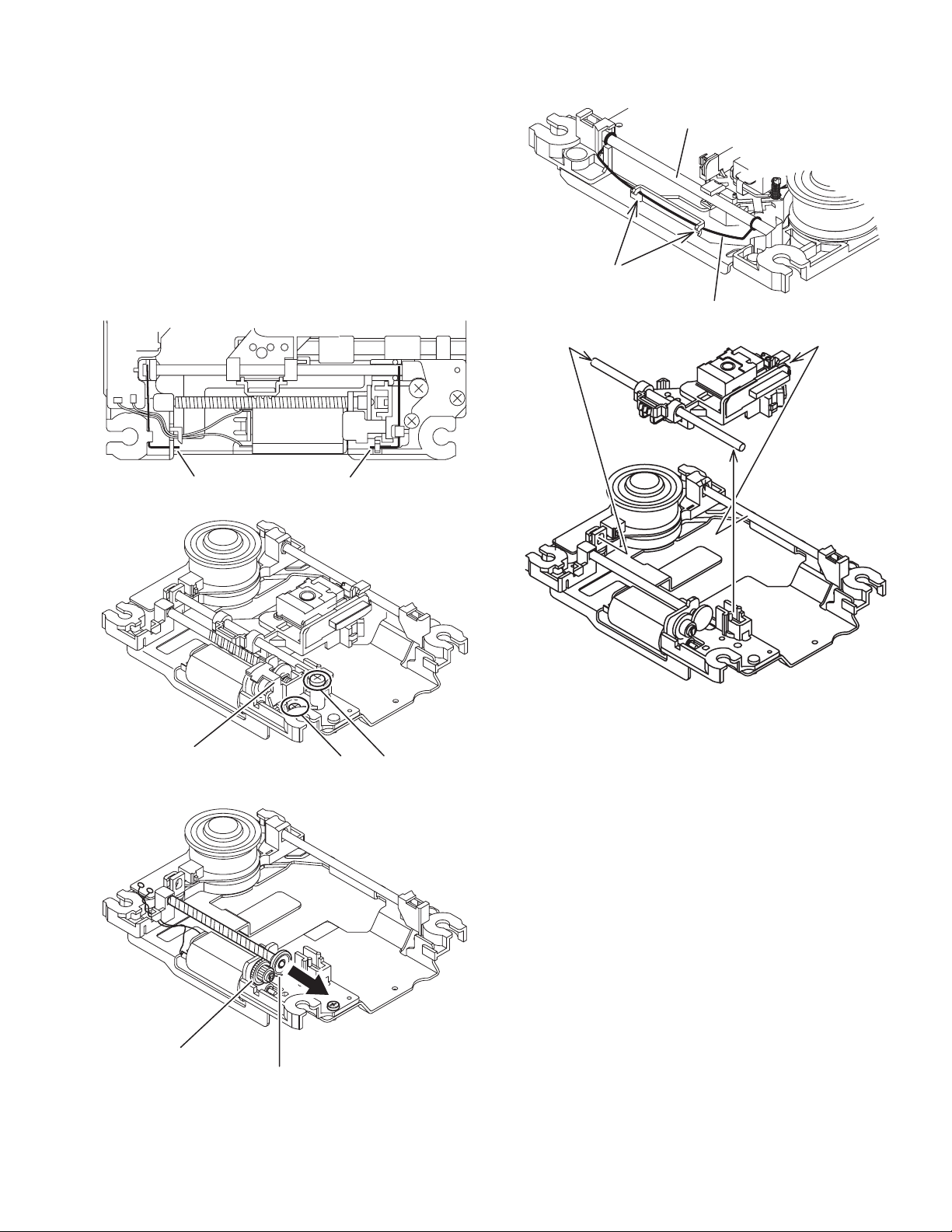
3.2.2 Removing the pickup assembly
(See Fig.7 to 11)
(1) Remove the two rod springs pressing the guide shaft. (See
Fig.7)
(2) Remove the screw E and F attaching the spring holder.
(See Fig.8)
(3) Remove the read screw from traverse mechanism assem-
bly. (See Fig.9)
Caution:
When remove the lead screw, do not loss the middle
gear. (See Fig.10 and 11)
(4) Remove the bar spring pressing the shaft. (See Fig.10)
(5) Take out the pickup assembly from traverse mechanism
chassis by order. (See Fig.11)
(SHAFT)
(T.TABLE)
HOOK
(BAR SPRING)
Fig.10
ROD SPRING ROD SPRING
Fig.7
Spring holder
Fig.8
order 2
order 3
order 1
Fig.11
EF
Middle gear
Lead screw
Fig.9
(No.MB726<Rev.001>)1-13
Page 14
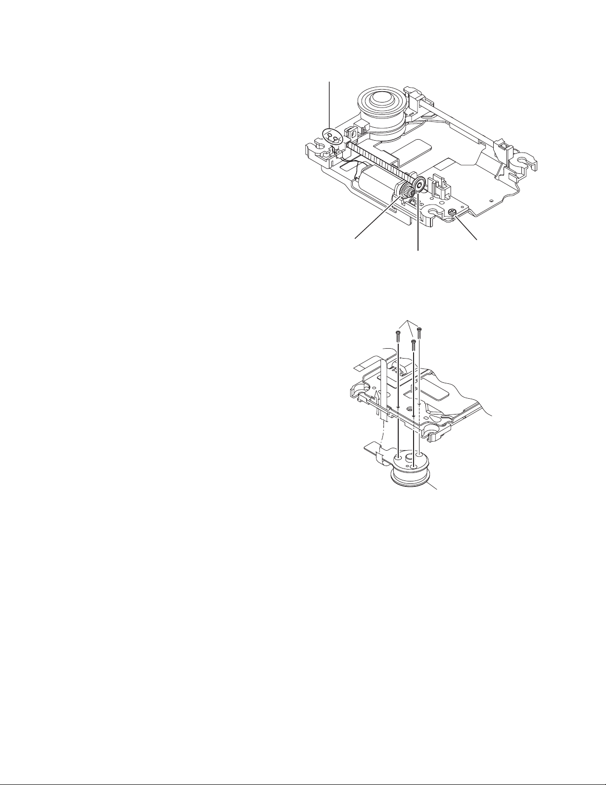
3.2.3 Removing the feed motor assembly
(See Fig.12)
(1) Remove the one screw G attaching the feed motor assem-
bly.
(2) Remove the feed motor wires from solder part of spindle
motor board.
Splder part
3.2.4 Removing the spindle motor assembly
(See Fig.13)
(1) Remove the three screws H attaching the spindle motor
from spindle motor board.
Middle gear
Lead screw
Fig.12
H
Spindle motor
Fig.13
G
1-14 (No.MB726<Rev.001>)
Page 15
3.2.5 Removing the tray assembly
(See Fig.14 & 15)
(1) Remove the two screws J attaching the clamper base.
(See Fig.14)
(2) Remove the one screw K attaching the shaft guide from
bottom side. (See Fig.14)
(3) Remove the two screws L attaching the shaft guide from
top side. (See Fig.15)
Caution:
When attach the tray assembly, boss of loading sub assembly
should attach to guide of bottom side at tray assembly. (See
Fig.15)
J
order 1
order 2
clamper base
L
K
Fig.15
[bottom side]
Fig.14
(No.MB726<Rev.001>)1-15
Page 16

SECTION 4
ADJUSTMENT
4.1 ATTENTION IN SERVICE OF DVD SECTION
1. When pickup, Flash ROM, DVD module board was changed, initialize EEPROM by all means.
2. When full initialization was executed, execute learning with a DVD test disc by all means.
Test disc: VT-501, VT-502
Learning method: It is adjusted automatically by normal playback of a DVD disc.
4.2 GENERAL
REMOTE KEY Validation INDICATION FUNCTION
STOP + "0" + POWER Press during Standby COLD COLD START (Initialization of set)
STOP + "1" + POWER Press during Power On (FL all light up) After CLOCK SET, run 1 minutes as 1sec
STOP + "2" + POWER Press during DVD/CD or USB eg:"A0D0S0T03BC" DVD temperature feedback
STOP + "3" + POWER Press once anytime eg: "POWERKEY" Power off/Safety trigger factor/cause
STOP + "4" + POWER Press during Power On eg:"FAN ON" Fan on/off trigger
STOP + "5" + POWER Press during Power On L0 C/SF/SH/SL/SE Lev_Det Status (L0/1/2), Calorie C****, Karaoke Score
SH,SF,SE,SL.
STOP + "6" + POWER Press during Power On VOLUME 15/MAX Trigger vol 15 or max
SET + "10" + POWER Press during Power On Refer SYSCON TEST Refer SYSCON TEST sheet
*Note :
(1) Tray Lock while press and hold panel "STOP" key then press "EJECT"
(2) AM spacing (In power on AM source, panel keys)
NX-D4
9K I<< + KARAOKE SCORING
10K >>I + KARAOKE SCORING
4.3 SYSTEM MICOM TEST MODE
(1) In DVD/CD mode, press "SET" key + "10" key + "POWER" key repeatedly.
System micom version
NX-D4 : "S D4 E 5600"
DVD/CD firmware version
"DVD 0317"
USB Telechip version
"USB 0000"
Touch Sensor
"TS 08"
1-16 (No.MB726<Rev.001>)
Page 17
4.4 Version reduction
4.4.1 Version setting writing way
Version information is written in test mode.
And version writing can do only first time.
After change version, password must be input if version need change.
(1) Step
1.Set goes DVD test mode.
2.Press remocon B336 (STOP+6+POWER) key
3.If first time, set show " VERSION U1"(Initial value)
If already updated, set show "LOCKED"
4.If number key is pressed , system show version.
(Refer to Version chart)
5.For NX-D4, if SETUP key is pressed, system show "OK"
"and write version to FLASH ROM.
(2) Step for LOCK release
3.If already updated, set show "LOCKED"
4.Enter password by number key.(4digit:0115)
*Note : Same password for all NX-D Series
5.If SETUP key is pressed and number is correct,
system show "OK" and write to flash.
If number is wrong, system show "NG".
Version
TEST x xy v w
U1
LOCKED
U2
U2 O K
LOCKED
1st
2nd
3rd
4th
* ___
*
*__
* **_
* ***
* *** O K
* *** N G
Key123456
VersionU1U2U3U4JC E
Notes
-Version can be changed for U versions, E and JC.
-Initial setting is U1.
-Version setting must backup and don't clear after cold set.
SECTION 5
TROUBLESHOOTING
This service manual does not describe TROUBLESHOOTING.
(No.MB726<Rev.001>)1-17
Page 18

Victor Company of Japan, Limited
Home Entertainment Business Division Personal AV Operation 10-1,1chome,Ohwatari-machi,Maebashi-city,371-8543,Japan
(No.MB726<Rev.001>)
Printed in Japan
VSE
Page 19

SCHEMATIC DIAGRAMS
36
COMPACT COMPONENT SYSTEM
NX-D4BNX-D4ENX-D4A
(No.MB726<Rev.001>)1/
Page 20
■ PRECAUTIONS ON SCHEMATIC DIAGRAMS
z Due to the improvement in performance, some part numbers shown in the circuit diagrams
may not agree with those indicated in the Parts List.
z The parts numbers, values and rated voltage etc. in the Schematic Diagrams are for
reference only.
z Since the circuit diagrams are standard ones, the circuits and circuit constants may be
subject to change for improvement without any notice.
■ PRECAUTIONS ON PARTS LIST
z
The parts identified by the symbol are critical for safety. Whenever replacing these parts, be sure to
use specified ones to secure the safety.
z
The parts not indicated in this Parts List and those which are filled with lines --- in the Parts No.
columns will not be supplied.
z
P.W. BOARD Ass'y will not be supplied, but those which are filled with the Parts No. in the Parts No.
columns will be supplied.
z
When ordering chips, screws etc., place bulk orders (unit of tens) whenever possible to improve
shipping efficiency.
z
There are cases where the actual implemented parts in the sets and the service parts are different.
When ordering parts, make sure to refer to the Parts List.
■
PRECAUTIONS ON SERVICE
Certain parts of the power circuits and the GNDs differ according to the models. Care must be
taken for the following points as the differences are indicated separately in the LIVE GND ( ) and
the ISOLATED (NEUTRAL) GND ( ).
1. Do not touch the LIVE GND, or do not touch the LIVE GND and the ISOLATED (NEUTRAL)
GND at the same time. It may cause an electric shock.
Before pulling out the chassis or other parts, make sure to pull out the power cord from the
wall outlet first.
2. Do not short circuit between the LIVE GND and ISOLATED (NEUTRAL) GND, or never
measure the LIVE GND and ISOLATED (NEUTRAL) GND at the same time using measuring
instruments (oscilloscope, etc.). It may blow fuses or damage other parts.
■ DEVIATION TOLERANCE RANGE
DEVIATION TOLERANCE RANGE
F G J K M N R H Z P
± 1% ± 2% ± 5% ±10% ±20% ±30%
+30%
-10%
+50%
-10%
+80%
-20%
+100%
-0%
36
(No.MB726<Rev.001>)2/
Page 21
Q9741Q9731
Q9201
Q7804
Q7801
AV_RETURN
Q6500
Q6220
RELAY
Q6200
SPI CCT
Q5700
Q5510
MUTING
Q5500
Q5301
Q5300
Q5201
AHB CCT
Q5200
Q5020
A9V / A6V REG.
Q5010
Q2450
LED DRV.
FAN DRIVE
Q2401
Q2400
Q1900
Q1501
SAFETY
Q1200Q1001
Q801
Q104
LASER DRIVER
Q101
IC974
USB5V REG.
IC973
IPOD AUDIO SW
IC972
IPOD VIDEO SW
IC971
IPOD
DECODER
IC970
IC921
LED DRV.
IC920
LED DRV.
IC902
I/O CONT.
LED DRV.
IC901
IR DET
IC880
IC801
ECHO &
SCORE
IC801
5V REG.
MIC AMP.
IC800
IC705
A5V REG.
AUDIO DAC
IC701
IC670
DC
DETECTION
IC650
OSC SELECT
IC610
LR AMP.
IC510
EEPROM
IC509
FLASH ROM
IC505
SDRAM
IC501
H.PHONE AMP
4
MIX
2
1
E.VOLUME
IC500
3
IC453
3.0V DET
IC421
VIDEO AMP
IC420
i-POD ISOLATION
IC400
3.3V REG.
IC305
IC303
48MHz
IC302
D1.2V REG.
DV5
IC301
VIDEO DRIVER
IC301
VIDEO MPX.
IC300
IC250
MOTOR DRV.
IC230
AMP MODE
IC225
IC221
RESET
MICON
IC220
DRIVER
IC201
DC/DC CONVERTER
IC100
,
X302,
to
DAC1 (Y/G_OUT)
DAC2 (PB_OUT)
DAC3 (PR_OUT)
DAC4 (Y_OUT)
DAC5 (C_OUT)
CV/PB
CN304
,
IPODB_TX, IPODB_RX, IPODB_DET, IPODB_PWR
IPODA_TX
IPODA_RX
IPODA_DET
IPODA_PWR
F_IPOD
European
versions only
J, C ver. only
USB_VBUS5V
D6V
iPOD dock PWB
SC/Y, SY/Pr, CV/Pb
LINE-IN_L
LINE-IN_R
AV_RETURN
RESET
DATA
CLK
RDSDATA
RDSCLK
RDSON
OUTL
OUTR
C/Py, Y/Pr, CV/Pb
IPOD_A/B
,
CN980 CN990
IPOD
DOCK-B
C/Py_Out
Y/Pr_Out
Cv/Pb_Out
F_IPOD
IPOD_RST
iPOD_DAT
IPOD_CLK
IPOD_A/B
IPODA_TX
IPODA_RX
IPODA_DET
IPODA_PWR
IPODB_TX
IPODB_RX
IPODB_DET
IPODB_PWR
,
TU_CE
TU_CLK
TU_DO
TU_DI
B+
SHORT WIRE FOR
120V SETTING
C/PY
Y/PR
CV/PB
CY, Cb, Cr
V_DVDIPOD
TRAY_OPN
TRAY_CLS
V_MUTE, VMUTE1
V_DVDIPOD, V_LPF
B+
Vol_1 to Vol_8
CN4
,
RY620, RY621
D2V
D4V
D6V
A13V
M9V
SAFETY
SYS_PON
B3.3V
D2V
D4V
D6V
A13V
M9V
S5V
B+
,
T1001
AMP_RY
FREQAMP
LEV_DET
DC_DET
AMP_MODE
AMP_ON
AMP_MUTE
A9V
A6V
A13V
HPSW
HPMUTE
HPL
HPR
AHB_ON
HPL, HPR
AUXL, AUXR
(COMPONENT)
VIDEO OUT
TRAY+, TRAY-
LOADING MOTOR
TRAY SW
M
CN307
CN306
Tuner Module
F+, F-
VDISP
F+, F-, VDISP
FL_CLK, FL_DAT, FL_LATCH
FL_BLANK, F_KEY1, LED_STBY
CN312
CN315
Remote
sensor
section
REM
M_LED
D8900
IR LED
FW315
FAN_SP
13V
TS_SCL
TS_SDA
TS_MCLR
CN301
B 3.3V
,,
D9200 to D9207
VOL LED
CN920
TOUCH
SENSOR
CN901
SCL
SDA/TXD
MCLR
LED
D9001 to 9012
Touch Board section
DIMMER, VOL_LED1
to VOL_LED4
CN900
F_KEY1
S8801 to S8806 FUNCTION KEY
LED_STBY
D8950 STANDBY LED
USB/JACK PWB
HPL, HPR
HPSW
AUXL
AUXR
HP
AUX-IN
CN840
J8400
CN811
J8300 J8401
MIC_DAT, MIC_CLK, MIC_FLG, RECL, RECR
MIX_OUT
MIC_SIG
MIC-IN
D6V
CN801
CN309
SDA, SCK
P3.3V
D4V
P3.3V
S3.3V
to
OSC
D6501, D6502
CN181
FW601
X6502
600KHz
X6501
700KHz
AMP_BEAT
(FREQAMP)
,
+B, -B
+28.5V, -28.5V
FAN_SP
MODE
LIN, RIN
CN503
CN600
LEV_DET
DC_DET
AHB_FB
D6901
AHB FB
,
D6701
D6801, D6803
LEVEL
DETECTION
+B, -B
,
Y, Pb, Pr
(COMPOSITE)
J3000
Y/G_OUT
PR_OUT
PB_OUT
TX
DIGITAL
OUT
VDISP, FL_CLK, FL_LATCH
FL_DAT, FL_BLANK
Amp section
DP, DM
D+, D-
USB5V
5V
NEN
D6V
F+, F-
D1.2V
DVDPWR
D2V
A5V
A6V
DVD
Pickup
Traverse
mechanism
Spindel
Motor
Feed
Motor
TUL, TUR
USB A
DVDL
DVDR
W8300
CN701
CN310
CN712
AHB_FB
SAOUT
DVDPWR
U2SDT, S2UDT, SCLK
SCS, UCS, CPURST
FAOUTL, FAOUTR
DVD section
LRMUTE
LRMUTE
TRVSW
SPDRV, FG
TRSDRV
FODRV
TRDRV
SPMUTE
LPCO1
LPCO2
CDLDCUR
DVDLDCUR
CN201
X301
27MHz
TX, DAC1OUT to DAC5OUT
SCS, UCS, UCLK, S2UDT, U2SDT
MA0 to 11, MDQ0 to 15
BA0, BA1, DQM0, DQM1
MCK, NCSM, NRAS
NCAS, NWE
NEXCE, NEXOE
NEXWE, EXDT0 to 15
EXADT0 to 15, EXADR16 to 20
Front panel
section
CPURST
CD-LD
DVD-LD
FM+, FM-
WOUT, VOUT
UOUT, COM
F+/-
T+/-
A, B, C, D, E, F, RF, VREFH, LPC1, LPC2
CN101
Power Unit
CN601
CN2
X2000
8MHz
RESET
VOL_DAT
VOL_CLK
L, R
VLOUT
VROUT
LEFT
RIGHT
MIC_CAL
MIC_CLK
MIC_DAT
MIC_FLAG
MIC_DET
TH_SAFETY1
INH
AMPPWER_SPLY
3.3V
THERMO
P.CONT
SYNC, VOLT
System control section
Mic circuit section
MIC_DET
MIC1
MIC2
J8000
J8001
MIC_CAL
CN800
SPI
FAN MOTOR
AC INPUT
CN1
CN180
CN3
CN850
FL display Section
FL870
FL DISPLAY
M
CN500
CN303
CPURST
OPNSW_TRY, CLOSW_TRY
D6V
C_OUT
Y_OUT
FAN_SFTY
+28.5V, -28.5V
AMP_RY
,
LOUT
ROUT
CN400
IPODL
IPODR
CN970
IPOD
DOCK-A
,
AV_RETURN
LINE-IN_L
LINE-IN_R
SC/Y, SY/Pr, CV/Pb
USB_VBUS5V
,
CN502
CN401
CN411CN411
MIC_SIG
REMCN_IN
MOTION_LED
RECL
RECR
J6100
SPEAKER
DCLK, DDATA, DACPDN
BCK, LRCK
DACCK
AOUT0
DAC0CS
CVBS
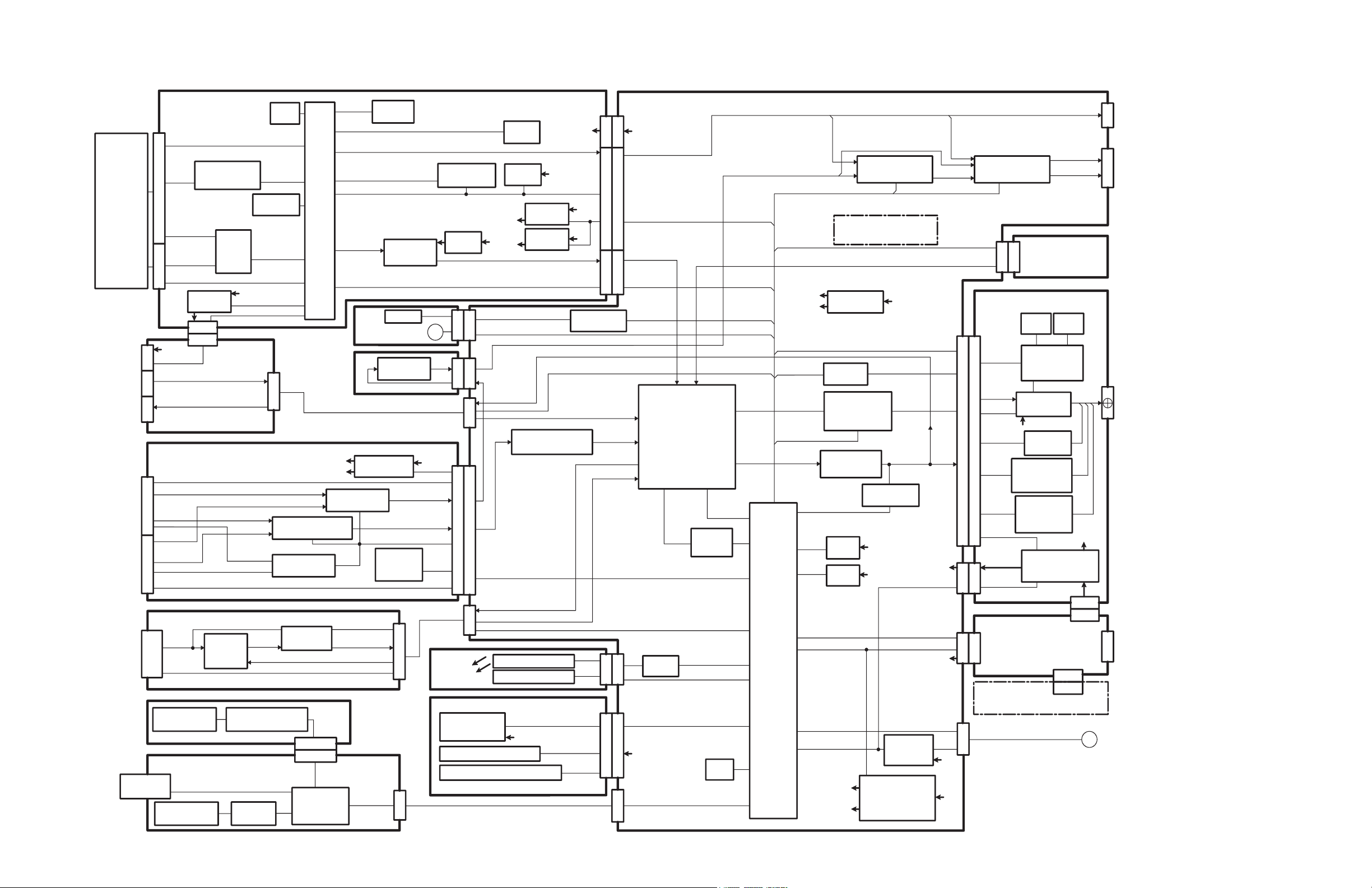
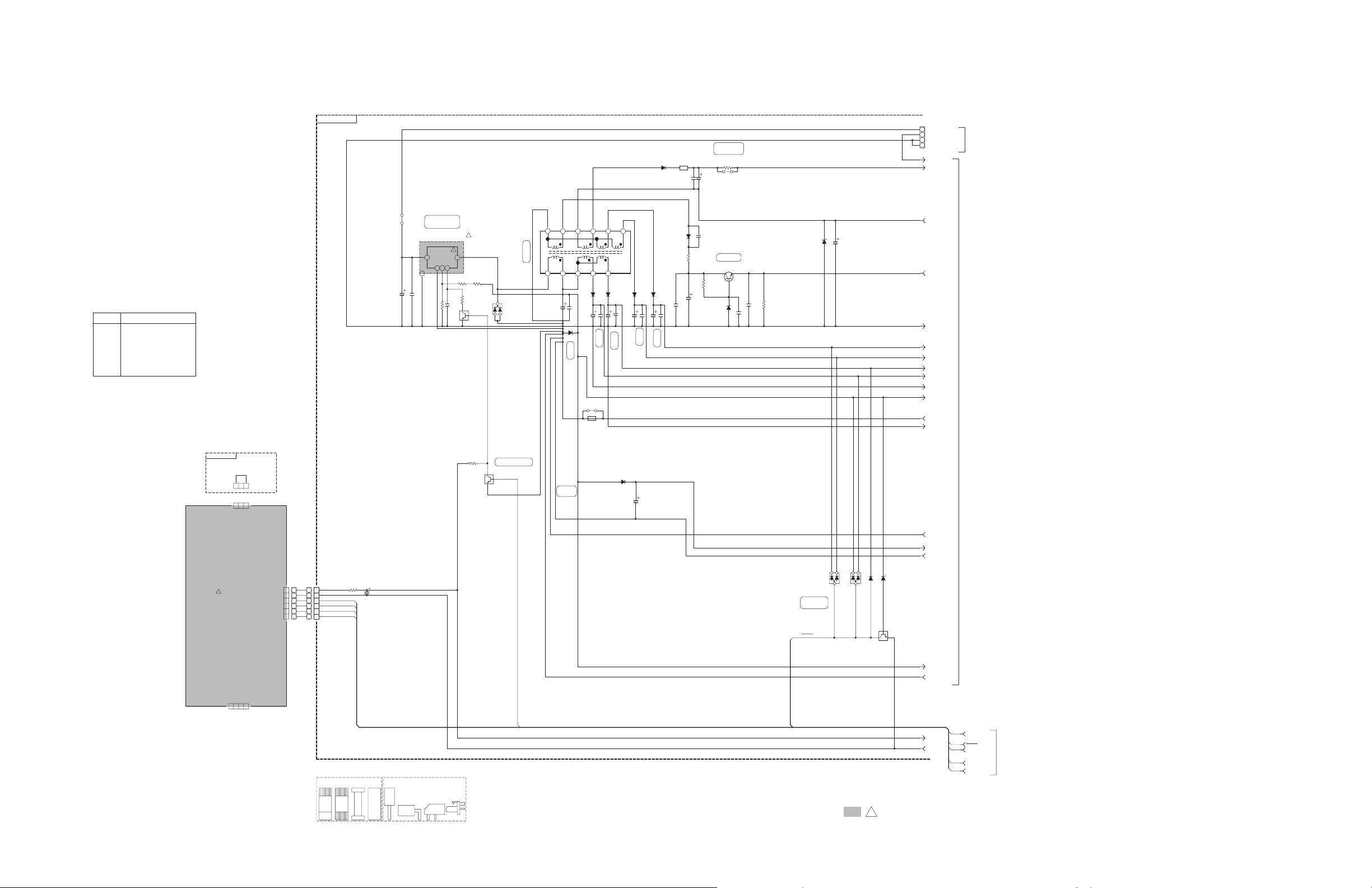
Block diagram
created date:2010-02-02No.MB726
36
(No.MB726<Rev.001>)3/
Page 22
38.3V
37.8V42.9V
0V
0V
2.5V
27.5V
0V
0V
0V
SHORT WIRE FOR 120V SETTING
Ver.C/J
123
1
6891011
5432
7
J :USA
E :EUROPE
OL EXT
C :CANANDA
005
003
VERSION CODES
002
006
A :AUSTRALIA
004
B :U.K.
32V
VDISP
F-
F+
VDISP
FILAMENT
FL
S5V
F2
BJ
CONNECTORWIRE AND FFC
C2
AJ
B2B
J1K1
ALL CAPACITORS ARE
5%ALL RESISTORS ARE 1/4W CARBON FILM RESISTOR
OF
±
ALL CAPACITANCE VALUES ARE IN F(P=pF).VOLT METER
CD STOP MODE
UNLESS OTHERWISE SPECIFIED. CAPACITANCE( F)
MYLAR CAPACITOR.
VOLTAGES ARE DC-MEASURED WITH A DIGITAL
ALL INDUCTANCE VALUES ARE IN H(m=mH). μ
1. ALL RESISTANCE VALUES ARE
3.
μ
OR
2.
NI STANDS FOR NOT INSERTED PARTS.
CERAMIC CAPACITOR
CONDITION ---
OR OSCILLOSCOPE WITHOUT INPUT SIGNAL.
ALL CAPACITORS ARE SHOWN IN THE FORM
/RATED VOLTAGE (V).
IN OHM( ). Ω
μ
0V
0V
+26.5V
-26.5V
QAL1059-002
4
3
2
1
6
5
4
3
2
1
6
5
CN4
CN2
CN3
GVA10182-A1
D6V
-B
AGND
1
+B
PGND
34 2
P.ON DRIVE
HEATSINK
3 2 1
SAFETY
TRANS
CONVERTER
DC/DC
SYNC
VOLT
THERMO
P.CONT
GND
+3.3V
0V
1.8V
3.3V
0.0V
0V
3.3V
6
5
4
3
2
1
ASS'Y
POWER UNIT
D2V
D4V
A13V
M9V
3.26V
0V
0V
0V
3.5V
3.6V
0.8V
0V
27.5V
2
543
1
6.64V
SWVIN
SS
ADJ
GND
SAFETY
TH_SAFETY1
SYS_PON
SYS_PON
INH
AMPPWR_SPLY
D6V
S5V
FAN_SP
F+
FLGND
12VGND
D2V
B3.3V
D6V
MGND
D4V
A13V
M9V
AMPPWR_SPLY
SYS_PON
F-
VGND
BGND
VDISP
TH_SAFETY1
DGND
TUGND
SAFETY
INH
IPODGND
!
!
sure to use the specified one.
When replacing those parts make
Parts are safety assurance parts.!
!
LV40057-001A
HS100
1/4W
10
R1200
UNF
100
R1005
24kR1201
2.7k
R1003
0
R1800
2.7k
R1004
SHORT
R1203
1k
R1202
1k
R1900
820R1002
KRC102S-X
Q1001
KRC102S-X
Q1900
KRC102S-X
Q1501
2SC3928A/RS/-X
Q1200
NI
K1100
2
3
1
MC2836-X
D1502
2
3
1
MC2836-X
D1501
3
1
2
FMB-24D1002
MA8024-X
D1207
MA8360/M/-X
D1206
BZT55C10-X
D1105
MA8068/M/-X
D1504
SK14-GA-X
D1104
SK34A-X
D1101
SK19-X
D1102
FR104S-T5
D1200
MA111-X
D1503
SK14-GA-X
D1208
SK26A-X
D1103
1N4003S-T5
D1400
ICP-N10-T
CP120
CP
1000/10
C1104
22/50
C1204
470/10
C1401
39/35
C1201
330/16
C1205
1000/10
C1103
100/16
C1800
330/25
C1101
470/25
C1102
1000/25
C1100
680/35
C1000
0.1/50C1002
0.47/50C1001
NIC1207
NIC1105
100p/1000
C1200
0.1
C1203
0.1C1202
NIC1107
NI
C1106
NI
C1206
NI
C1109
NI
C1108
B2030
NRS144J-0R0X
B3100
B2046
SI-8008HFE-F3
IC100
QQS0445-001T1001
6
5
4
3
2
1
QGA2536C1-06
CN180
PGND4
PGND3
FAN_SP2
+B1
QGD2504C1-04Z
CN181
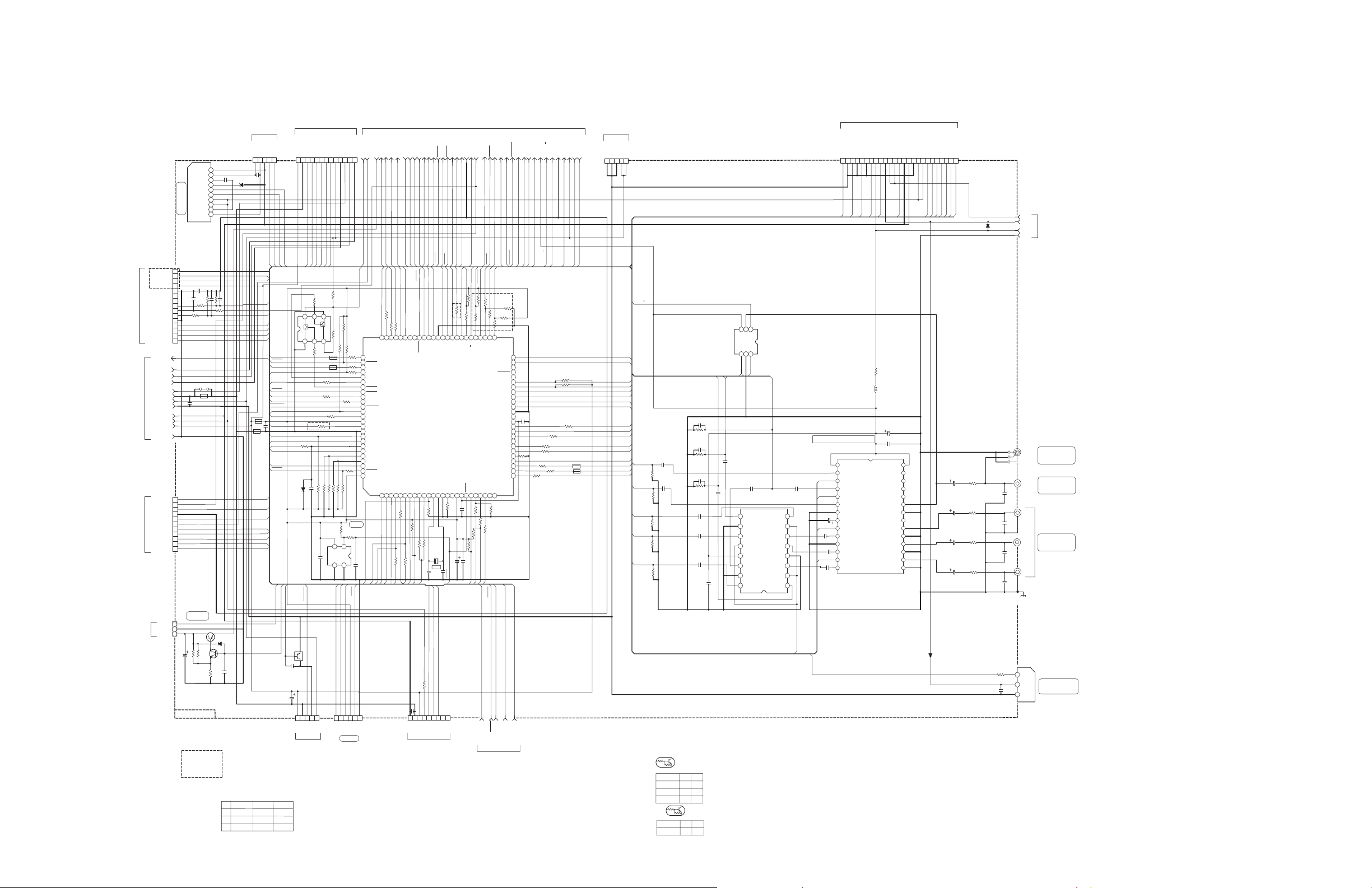
<Main section 1>
FW601
To Power AMP section
To Main section 2
To Main section 2
created date:2010-02-02No.MB726
36
(No.MB726<Rev.001>)4/
Page 23
0V
0V
5.9V
0V
0V
5.9V
0V
3.7V
3.3V
0V
9.2V
0V
3.3V
0V
0V
0V
0V
0V
3.3V
0V
4.8V
0V
4.8V
3.3V
0V
9.6V
0V
0V
3.3V
0V
0V
3.3V
0V
2.6V
0V
3.3V
9.2V0V0V
2.6V
3.3V
3.3V
5.4V0V6.1V
0.6V
0V
1.1V
0.8V
0.6V
9.2V
0V
9.2V
0V
0.8V
0V
0.6V0V0.6V
0V
3.2V
0V
0V
6.1V
3.3V
0V
6.9V
3.2V0V3.3V
0V
2.8V
0.3V
0V
5.4V
0.9V
2V
0V
1.6V
0.5V
0.5V
2V
0V
3.3V
4.1V
9.4V
3.3V
9.4V
3.3V
0.8V
3.3V0V3.3V
3.3V0V3.3V
0.9V
0V
6.1V
6.1V
0V0V0V
0V
4.98V
1.8V
0V
2.4V
2.4V
0V
0V
1.75V
3.3V
2.4V
2.4V
0V
1.44V
3.3V
2.4V
0V
1.44V
0V
1.13V
3.3V
2.34V
4.98V
2.88V
0V
2V
0V
2V
1.5V
0V
2.3V
2.7V
0V
2.88V
4.98V
0V
2.7V
0V
2.1V
3.3V
0V
0V
2.4V
1V
0V
1.8V
0V
3.3V
0V
3.3V
3.3V
3.3V
0V
3.3V
0V
3.3V
3.3V
0V
3.3V
0V
3.2V
0V
3.3V
3.3V
3.3V
0V0V0V
0V
0V
0.3V
3.3V
0V
0V
0V
0V
3.3V
3.3V
3.7V
2.45V
0V
3.3V
0V
0V
3.3V
3.3V
0V
0V
2.4V
3.3V
1.54V
1.59V
1.87V
0V
3.3V
0V
0V
0V
0V
0V
0V
0.43V
3.3V
0V
3.3V
3.3V
3.3V
3.3V
0V
0V
0V
0V
0V
1.8V
0V
3.3V
3.3V
0V
3.3V
0V
3.3V
3.3V
3.3V
0V
0V
0V
2.98V
0V
0V
0V
3.3V
3.3V
0V
0V
*D2 ONLY
*D4 ONLY
*D4 ONLY
*D2 ONLY
(COMPOSITE)
VIDEO OUT
A
U1
J,C
3.3K
10K
J
E,B
VERSION
NI10KE
####
NI
R2197R2097
10K
AGENDA:
* NX-D5/D7 ONLY
# NX-DC3/D4 ONLY
#
** NX-D4/D5/D7 ONLY
%
% E VERSION ONLY
%
QGF1208C1-15
E. VER ONLY
RST
3.3V
NC
GND
0V
VCC
0V
GVA10182-A1
FAN DRIVER
FOR FLASH
2.1V
1.5V
7.2V
/RS/-X
2SC3928A
13.2V
12.5V
DIGITAL OUT
Pr
(COMPOSITE)
VIDEO DRIVER CIRCUIT
Pb
VIDEO OUT
(COMPONENT)
VIDEO OUT
V
Y
10K10KKRC102S-X
KRC111S-X
RT1N140C-X
CARBON FILM RESISTORALL RESISTORS ARE
VOLTAGES ARE DC-MEASURED WITH A DIGITAL
ALL CAPACITORS ARE
1/4W
CAPACITANCE( F)
CD/DVD STOP MODE
NOTES
μ
IN OHM( ).
/RATED VOLTAGE (V).
OR OSCILLOSCOPE WITHOUT INPUT SIGNAL.
1.
±
VOLT METER
RT1P141C-X
ALL RESISTANCE VALUES ARE
R1
UNLESS OTHERWISE SPECIFIED.
R2
ALL INDUCTANCE VALUES ARE IN H(m=mH).
10K
ALL CAPACITORS ARE SHOWN IN THE FORM
10K
R2
CERAMIC CAPACITOR
R1
μ
10K -
R1 R2
10K
-
R1
R2
5.DIGITAL TRANSISTOR
4."0"= SHORT BY PATTERN
OF
CONDITION ---
ALL CAPACITANCE VALUES ARE IN F(P=pF).
ALL DIODES ARE MA111-X OR 1SS133-T2
MYLAR CAPACITOR.
5%
3.NI MEANS NO INSERT
2.
OR
Ω
μ
DVD MOTOR DRIVER
RESET
8MHZ
CV/PB
IPOD_A/B
CV/PB
C/PY
C/PY
FAN_SP
F_IPOD
Y/PR
FAN_SP
V_MUTE1
IPODB_TX
MIC_CLKMIC_CLK
FL_LATCH
FL_BLANK
FL_DAT
FL_CLK
MIC_DAT
MIC_DAT
DC_DET
MIC_FLAG
LRMUTE
D6V
IPODB_TX
IPODB_RX
IPODB_PWR
IPODA_PWR
IPOD_CLK
FAN_SFTY
IPODA_TX
IPODB_RX
TS_SCL
HPMUTE
AHB_ON
AMP_MODE
FREQAMP
IPODA_RX
AMP_RY
TU_CE
AHB_SW
TU_DI
TU_CLK
TU_DO
LRMUTE
HPSW
TUL
IPOD_A/B
IPODB_DET
IPOD_RST
IPOD_DAT
IPODA_DET
V_LPF
V_DVDIPOD
OPNSW_TRY
CLOSW_TRY
TRAY_OPN
TRAY_CLS
V_MUTE
TS_MCLR
AMPPWR_SPLY
TS_SDA
MIC_DET
RESET
F_IPOD
FAN_SP
FAN_SFTY
SYS_PON
FLS_DAT
PR_OUT
PB_OUT
Y/G_OUT
IPODA_PWR
IPODB_PWR
MIC_SIG
RDSDAT
RDSON
RDSCLK
RDSDAT
IPOD_RST
IPOD_DAT
IPOD_CLK
C_OUT
Y_OUT
SAFETY
RDSCLK
V_DVDIPOD
V_DVDIPOD
V_MUTE
V_MUTE1
V_LPF
MOTION_LED
FLS_DAT
TS_MCLR
TH_SAFETY1
SPI
F_KEY1
INH
LEV_DET
LED_STBY
IPODB_DET
RECL
AHB_SW
IPODA_DET
AMP_RY
HPMUTE
AHB_ON
VOL_CLK
VOL_DAT
CV/PB
C/PY
Y/PR
VOL_CLK
VOL_DAT
UCS
U2SDT
DVDPWR
REMCN_IN
MOTION_LED
SPI
RDSON
MIC_SIG
TUR
TUL
RECR
IPOD_A/B
FLS_CLK
CPURST
MMOD
RESET
HPSW
IPODA_TX
IPODA_RX
RECL
RECR
MIC_DET
MIC_CAL
TH_SAFETY1
MIC_CAL
LEV_DET
TUR
SCLK
S2UDT
FLS_CLK
MMOD
TS_SDA
TS_SCL
SYS_PON
INH
SAFETY
AMPPWR_SPLY
C_OUT
FL_CLK
FL_BLANK
LED_STBY
F_KEY1
FL_DAT
AMP_MODE
TX
SCS
FL_LATCH
TU_CE
MIC_FLAG
MIC_DAT
MIC_CLK
TRAY_OPN
TRAY_CLS
CLOSW_TRY
OPNSW_TRY
TU_DI
TU_CLK
TU_DO
FREQAMP
DC_DET
REMCN_IN
TX
Y_OUT
Y/G_OUT
PB_OUT
PR_OUT
SCLK
DVDPWR
U2SDT
S2UDT
SCS
UCS
CPURST
IPODA_PWR
IPODB_PWR
AMP_RY
LEV_DET
AMP_MODE
HPMUTE
AHB_ON
VOL_CLK
VOL_DAT
TUL
TUR
AHB_SW
IPODA_TX
FREQAMP
IPODA_RX
F_IPOD
FAN_SP
V5V
IPOD_A/B
RECR
LRMUTE
IPODB_TX
IPODB_RX
AGND
RECL
D6V
IPOD_RST
IPOD_DAT
IPOD_CLK
SPI
12VGND
FLGND
BGND
D6V
DGND
MGND
M9V
D4V
D2V
VGND
B3.3V
SYS_PON
SAFETY
INH
AMPPWR_SPLY
TH_SAFETY1
CV/PB
C/PY
Y/PR
HPSW
IPODA_DET
DC_DET
AGND
A9V
A13V
A5.5V
S5V
VDISP
IPODB_DET
F+
F-
MIC_SIG
QAX0711-002Z
X2000
1K
R2101
1K
R2074
R3005
NI
R3011 75
10K
R2150
R2096
30K
R2097
####
R2196
10K
220
R2401
1K
R2094
820
R2250
R2197
####
10K
R2155
R3004
200
12K
R2611
10K
R2192
1K
R2075
1K
R2026
10K
R2126
220
R2008
10K
R2187
10K
R2179
1K
R2081
1K
R2048
1K
R2049
10K
R2149
NI
R2146
10K
R2138
1.5K
R2040
680
R2041
1K
R2036
1K R2035
10K
R2120
1K
R2004
R3010 75
1K
R2023
1KR2032
1KR2031
1K
R2033
1K
R2076
1K
R2079
1K
R2077
1K
R2078
1
R3001
10K
R2168
R3000
200
7.5K
R2610
4.7
R1302
220
R2084
220
R2082
2.7K
R2050
1k
R2200
1K
R2054
R3007
NI
R3008
200
1K
R2068
12K
R2601
NI
R2169
10K
R2166
10K
R2167
1.5K
R2403
R3006
200
R3012 75
1K
R2006
R3002
200
1K
R2088
1K
R2025
R2500
47
1.5K
R2402
4.7K
R2011
1K
R2055
1K
R2046
1K
R2072
1K
R2099
1
R2700
7.5K
R2600
1K
R2015
10k
R2119
10K
R2199
R3003
NI
1K
R2005
1K
R2073
1K
R2021
1K
R2022
R3013 75
KTC3875/YG/-X
Q2450
Q2401
KTA1273/Y/-T
Q2400
L3000
220
SHORT
K2078
SHORT
K2076
NI
K2400
SHORT
K2077
NQR0502-001X
K2000
NQR0502-001X
K2001
SHORT
K2075
VREF+100
SAFETY99
LEV_DET98
VERSION97
MODEL96
SPI95
PWR_THERMO94
MIC_CAL93
F_KEY192
VSS91
HPMUTE90
VDD3.389
RDSCLK88
INH87
REMOCON86
VOL_DAT85
VOL_CLK84
AHB_ON83
AMP_ON82
MIC_CLK81
AMP_MUTE80
MIC_DAT79
FL_CLK78
DC_DET77
FL_DAT76
FREQAMP
75
AMP_RY
74
IPA2S_DT73S2IPA_DT
72
LED_STBY
71
IPODB_PWR
70
SW_LV169SW_LV2
68
AHB_SW
67
TU_CE
66
TU_DI
65
TU_CLK
64
VSS
63
TU_DO
62
RDS_ON
61
IPODA_PWR
60
RDS_DATA
59
LRMUTE
58
HPSW
57
IPOD_A/B
56
IPODB_DET
55
IPOD_RST54IPOD_DAT
53
IPOD_CLK
52
IPODA_DET
51
V_LPF 50
V_DVDIPOD
49
TELEPWR 48
TELERST 47
CEC_OUT 46
OPNSW_TRY 45
CLOSW_TRY 44
TRAY_OPEN 43
TRAY_CLS 42
V_MUTE1 41
V_MUTE 40
VSS 39
CEC_IN 38
VDD18 37
TS_MCLR 36
AMPPWR_SPLY 35
TS_SCL 34
NC 33
IPB2S_DT 32
S2IPB_DT 31
CBTEST 30
UCS 29
FL_BLANK 28
FL_LATCH 27
TS_SDA 26
NC25NC24MOTION_LED23MIC_DET22MIC_FLAG21F_IPOD20RESET19VDD1818VDD33/FLS_VDD
17XO16XI15
VSS14OSC113OSC212MMOD11FAN_ON10FAN_H9FAN_SFTY8SYS_PON7SCLK6U2SDT5S2UDT4CPURST3SCS2DVDPWR
1
MN101EF16KXW
IC220
VCC1
1
C In
2
MUTE1
3
CVBS In
4
YC MIX
5
Y In
6
GND1
7
BIAS
8
I/P
9
CY In
10
CLP
11
Cb In
12
MUTE2
13
Cr In
14
GND2
15
Cr Out
16
GND2
17
Cb Out
18
GND2
19
CY Out
20
Y Out
21
GND2
22
CVBS Out
23
S2
24
S1
25
C Out
26
S-DC oUT
27
VCC2
28
MM1623XF-X
IC301
PyIN1
8
CTLC
7
PyOUT
6
PbOUT
5
GND
4
PrOUT
3
CTLA
2
PrIN2
1
PyIN2
9
GND
10
PbIN1
11
CTLB
12
VCC
13
PbIN2
14
GND
15
PrIN1
16
MM1732XV-X
IC300
OUT2
10
P2
9
VCC2
8
VCC1
7
IN2
6
IN1
5
VZ
4
P1
3
OUT1
2
GND
1
LB1641
IC230
IN1
6
GND
5
IN2
4
VCC3OUT
2SW1
NI
IC302
6 5 4
321
KTC801U/G/-X
IC225
43
2 1
S-80827CNNB-G-W
IC221
VSS
3
VDD
2
IN
1
GP1FAV30TK0F
IC250
MA8047/M/-X
D2300
MA111-X
D2400
MA111-X
D2500
NI
D2100
D2194
10/50
C2400
100/16
C2451
22/50
C3016
100/16
C2017
100/16
C3019
C3026
470/10
C3027
470/10
C3025
470/10
C3024
470/10
C3004
1/16
C3007
1/16
C3003
1/16
C3028
47p
C3008
1/16
C3002
1/16
C3030
47p
NI
C2008
0.1/16
C2117
0.1/16
C2094
NI
C3011
0.1/50
C2018
1/16
C2037
C3006
1/16
NI
C3012
NI
C3010
C3018
0.1/16
NI
C1801
C2500
0.1/16
0.1/16
C2301
1000P
C2601
1000P
C2611
C2700
NI
C3009
NI
C2401
1/16
C2450
NI
C3029
47p
1/16
C3000
1/16
C3015
0.1/16
C2300
18P/50
C2012
1/16
C3013
1/16
C3014
1/16
C3005
C3031
47p
0.1/50
C2089
1/16
C1302
0.01
C2200
C2019 0.1/16
1/16
C3001
33P/50
C2013
B2017
213
QNN0780-002
J3001
1
QNN0841-001
J3000
4
5
6
2
3
CPURST25
UCS24
SCS23
SCLK22
S2UDT21
U2SDT20
DVDPWR19
M9V18
M9V17
RX16
MGND15
MGND14
TX13
D2V12
D2V11
D4V10
C_OUT9
S5V8
DAC4OUT(Y)7
DGND6
DAC1OUT(Y/G)5
DGND4
DAC2OUT(Cb/B)3
DGND2
DAC3OUT(Cr/R)1
QGF1036C2-25
CN310
TU_CE 1
TU_DI 2
TU_CLK 3
TU_DO 4
TUGND 5
TUL 6
TU9V 7
TUR 8
NC 9
NC 10
TUGND 11
3.3V 12
RDSON 13
RDSCLK 14
RDSDATA 15
QGF1208C1-11
CN306
B3.3V13
BGND12
LED_STBY11
F_KEY110
FL_BLANK9
FL_DAT8
FL_LATCH7
FL_CLK6
D6V5
FLGND4
VDISP3
F-2
F+1
QGF1208C1-13
CN312
MIC_SIG
11
A9V
10
RECR 9
AGND 8
RECL
7
A5.5V 6
MIC_DET
5
MIC_CAL
4
MIC_CLK 3
MIC_FLAG
2
MIC_DAT 1
QGF1208C1-11
CN304
NC 9
NC 8
MCLR 7
SDA 6
SCL 5
M9V 4
3.3V 3
BGND 2
MGND 1
QGF1036C2-09
CN301
FLS_CLK 6
MMOD 5
FLS_DAT 4
VDD 3
RESET 2
DGND 1
QGF1208C1-06
CN302
B3.3 5
BGND 4
REM 3
M_LED 2
D6V 1
QGD2504C1-05Z
CN315
CLOSW_TRY5
OPNSW_TRY4
MGND3
TRAY-2
TRAY+1
QGF1036C2-05
CN307
DGND5
DGND4
DGND3
D6V2
D6V1
QGF1036C2-05
CN309
FAN_SFTY 3
MGND 2
+12V 1
QGA2501C1-03
CN303
CN1
To DVD loading switch section
<Main section 2>
CN850
To Display section
To Main section 3
CN701
To DVD module section 2
To Main section 1
To Main section 1
CN900
To Touch section
FW315
To Sensor section
To FAN MOTOR
CN800
To Mic section
To Main section 1
To TUNER MODULE
CN801
To DVD module section 3
created date:2010-02-02No.MB726
36
(No.MB726<Rev.001>)5/
Page 24
VGND
A5V
Audio_Rtn
Y/Pr_In
0V0V0V0V0V0V0V
3.3V
0.82V
0V
0V
13V
0V
0V
6.1V
0V0V6V
0V
0V
0V
0V
0V
0V
0V
3.5V
3.5V
4.8V
9.6V
0V
4.8V
3.5V
3.5V
0V
3.3V
2.47V
2.47V
5.67V
4.83V
4.86V4.8V
4.82V
0V
4.9V
9.54V
4.92V
0V
-2.1V
0V
-2.1V
0V
0V
9.6V
0V
0V
9.6V
0V
0V
0V
9.5V
9.5V
0V0V0V
0V
-2.1V
0V
0V
0V
0.68V
6.3V
9.6V
5.7V
10.2V
11.4V 9.56V
4.8V
4.8V
4.8V
4.8V
4.8V
4.8V
4.8V
4.8V
4.8V
4.8V
4.8V
4.8V
4.8V
4.8V
4.8V
0V
0V
4.8V
4.8V
4.8V
4.8V
4.8V
4.8V
4.8V
4.8V
4.8V
4.8V
4.8V
4.8V
4.8V
4.8V
4.8V
4.8V
4.8V
0V
4.8V
4.8V
4.8V
9.6V
4.8V
0V
2.9V
0V
2.9V
0V
0V
4.8V
3.3V
0V
0V
0V
0V
6.1V
3.3V
3.3V
3.3V
3.3V
0V
3.3V
0V
3.3V
1.15V
3.3V
6.1V
1.13V
1.86V
1.86V
*
MAIN AHB_FB
*
DVD FRONT
SPI CIRCUIT
i-POD ISOLATION CCT.
*
VOLUME IC
H.PHONE_AMP/PRE_LIMITER
VDD
AHB_MAIN
H.PHONE MUTE
VSS
A9V REGULATOR
*
*
*
GVA10182-A1
ALL DIODES MA111-X UNLESS SPECIFIED
A6V
FAOUTR
AGND
FAOUTL
LRMUTE
A6V REGULATOR
Y/PR
C/PY
CV/PB
Y/PR_IN
C/PY_IN
CV/PB_IN
IPODA_PWR
F_IPOD
F_IPOD
CV/PB_IN
IPODA_TX
IPODA_DET
IPODB_TX
SPI
AUXR
12VGND
IPOD_RST
VOL_CLK
IPODB_PWR
IPODB_DET
IPODB_RX
IPODA_RX
IPODB_RX
IPODB_TX
HPMUTE
VOL_DAT
TUL
IPODL
HPR
HPL
IPODA_PWR
IPODB_PWR
IPOD_A/B
C/PY_IN
Y/PR_IN
IPOD_DAT
IPOD_CLK
IPOD_RST
IPOD_DAT
IPOD_CLK
VOL_DAT
IPOD_A/B
HPMUTE
LRMUTE
DVDR
RECL
RECR
IPODB_DET
ROUT
LOUT
AMP_RY
AMP_RY
AHB_ON
AHB_FB
AHB_FB
AMP_MODE
FREQAMP
LEV_DET
DC_DET
ROUT
LOUT
DC_DET
AMP_MODE
LEV_DET
FREQAMP
IPODA_DET
CV/PB
C/PY
Y/PR
IPODA_TX
IPODA_RX
SPI
AHB_SW
TUL
TUR
AHB_ON
VOL_CLK
HPSW
LRMUTE
HPSW
MIC_SIG
AUXL
HPR
HPL
IPODR
IPODL
IPODR
MIC_SIG
RECL
DVDR
DVDL
AUXR
AUXL
TUR
DVDL
RECR
DC_DET
SPI
Y/PR
CV/PB
A9V
A5.5V
HPSW
C/PY
LRMUTE
LEV_DET
IPODB_PWR
F_IPOD
FREQAMP
IPODA_DET
IPODA_TX
IPODA_RX
AMP_MODE
TUR
AHB_ON
VOL_CLK
VOL_DAT
HPMUTE
D6V
IPODGND
A13V
AGND
TUL
D6V
AMP_RY
IPODB_DET
AGND
MIC_SIG
RECR
RECL
IPOD_A/B
12VGND
B3.3V
12VGND
IPODA_PWR
V5V
IPODB_RX
IPODB_TX
IPOD_RST
IPOD_DAT
IPOD_CLK
VGND
AHB_SW
+
-
+
-
+
-
+
-
1
W4000
7
W40066W40045W40054W4003
2.2K
R5203
680K
R5701
15K
R5312
33k
R4402
22k
R4400
15K
R5212
470
R4500
10k
R4502
2.2K
R5303
1K
R5202
560
R5020
1K
R5302
NI
R5703
SHORT
R5454
10k
R4501
8.2K
R5451
SHORT
R5702
150K
R5309
120K
R5453
10K
R5704
2.2K
R5301
8.2K
R5204
100k
R4210
56K
R5450
100
R5206
100
R5306
100
R5307
150K
R5209
1M
R5308
1M
R5208
6.2K
R5213
2.2K
R5500
100k
R4211
22k
R4300
33k
R4303
8.2K
R5304
1.5K
R5101
1.5K
R5111
7.5K
R5102
22K
R5314
33kR4302
22K
R5214
7.5K
R5112
12K
R5700
4.7K
R55054.7KR5515
12K
R5452
560
R5010
10KR5511
22k
R4401
22
R5512
2.2K
R5510
1/4W
UNF
4.7
R5000
15K
R5706
4.7K
R5200
100
R5207
10KR5400
22k
R4301
33k
R4403
22
R5502
6.2K
R5313
10K
R5501
22
R5705
2.2K
R5201
4.7K
R5300
KRA102S-X
Q5510
RT6N230C-X
Q5700
KTC3203/OY/-T
Q5010
KTC3875/YG/-X
Q5200
KTC3203/OY/-T
Q5020
KTC3875/YG/-X
Q5300
L4000
47
NI
K4008
L240
L139
VCC38
MIX237
MIX136
SUR235
SUR134
REFIN33
AGND32
R131
R230R329R4
28
RECR
27
RBASS126RBASS2
25
RTRE
24
RMID123RMID2
22
RTONEOUT
21
RVOLIN 20
RVOLOUT 19
ROPIN 18
VROUT 17
VDATAMAIN 16
VOLCLK 15
VLOUT 14
LOPIN 13
LVOLOUT 12
LVOLIN 11
LTONEOUT10LMID29LMID18LTRE7LBASS26LBASS15SAOUT4RECL3L42L3
1
R2S15207FP-X
IC500
1234
8765
NJM4565E-X
IC501
3 5 4
621
KTC801U/G/-X
Q5201
3 5 4
621
KTC801U/G/-X
Q5301
654
3 2 1
RT3X99M-X
Q5500
3
1
2
NI
D4000
MA8062/M/-X
D5020
MA8100/M/-X
D5010
D5701
D5450
NI
D5700
D5451
NI
D5452
D5021
100/16
C5010
220/10
C5103
22/63
C5101
10/63
C4400
1/50
C5700
100/16
C5554
220/10
C5012
NI
C4011
2.2/63
C5205
22/63
C5020
2.2/63
C5305
10/63
C5300
10/63
C5303
10/63
C5202
10/63
C5201
10/63
C5304
10/63
C5301
1/50
C5551
100/16C4501
100/16C4502
22/63
C5502
10/63
C5204
10/63
C5212
10/63
C5312
100/16
C5701
1/50
C5702
10/63
C5200
100/16
C5403
10/63
C5302
100/16
C5400
100/16
C5550
22/63
C5111
1/50
C5401
1/50
C5453
10/63
C5450
10/63
C5203
10/63
C4300
22/63
C5512
NIC4005
100P/50
C5404
470P
C5313
470P
C5213
0.047
C4500
100pC4403
27P/50
C5501
MY
3300P
C5207
27P/50C5511
MY
0.33
C5208
10p
C4301
100pC4302
MY
0.33
C5209
MY
0.33
C5206
0.01/50
C5409
0.15/10
C5451
100p
C4303
10p
C4401
NI
C5452
NIC4009
100p
C4402
NI
C4010
NIC4003
NI
C4000
NIC4001
0.047
C5402
NIC4004
1/16
C5011
0.1/16
C5552
1/16
C5021
0.1/16C4503
0.1/16
C5553
0.15
C5211
NIC4006
NIC4018
NIC4020
NIC4021
0.33
C5306
1000P/50
C5102
1000P/50
C5112
0.1
C5210
3300P
C5307
100P/50
C5405
0.1
C5310
0.15
C5311
0.33
C5309
0.1/16
C5408
0.33
C5308
W4001
B2051
B2050
B2121
B2408
1
3
2
+
-
4
8
7
5
6
NJM4565E-X
IC400
+
-
RESET 27
B3.3V 26
CLK 25
DATA 24
A5V 23
IPODB_DET 22
IPODB_PWR 21
IPODB_TX 20
IPODB_RX 19
AGND 18
C/Py 17
Y/Pr 16
CV/Pb 15
IPOD_A/B 14
VGND 13
F_IPOD 12
AUDIO_RETURN 11
OUTR 10
OUTL 9
IPODA_PWR 8
IPODA_DET 7
IPODA_RX 6
IPODA_TX 5
D6V 4
D6V 3
DGND 2
DGND 1
QGF1036C2-27
CN400
DGND15
D6V14
A13V13
AMP_RY12
AMP_BEAT11
LEV_DET10
DC DET9
MODE8
SWAHB_FB7
SW_IN 6
SWGND5
AHB_FB4
RIN3
MAINGND2
LIN1
QGF1208C1-15
CN503
AUXR7
AUX_GND6
AUXL5
HPSW4
HPL3
HPGND2
HPR1
QGF1208C1-07
CN502
5
4
3
2
1
QGF1036C2-05
CN500
Cv/Pb_Out 3
C/Py_Out 2
Y/Pr_Out 1
CN412
Cv_Pb_In 9
C/Py_In 8
CN411
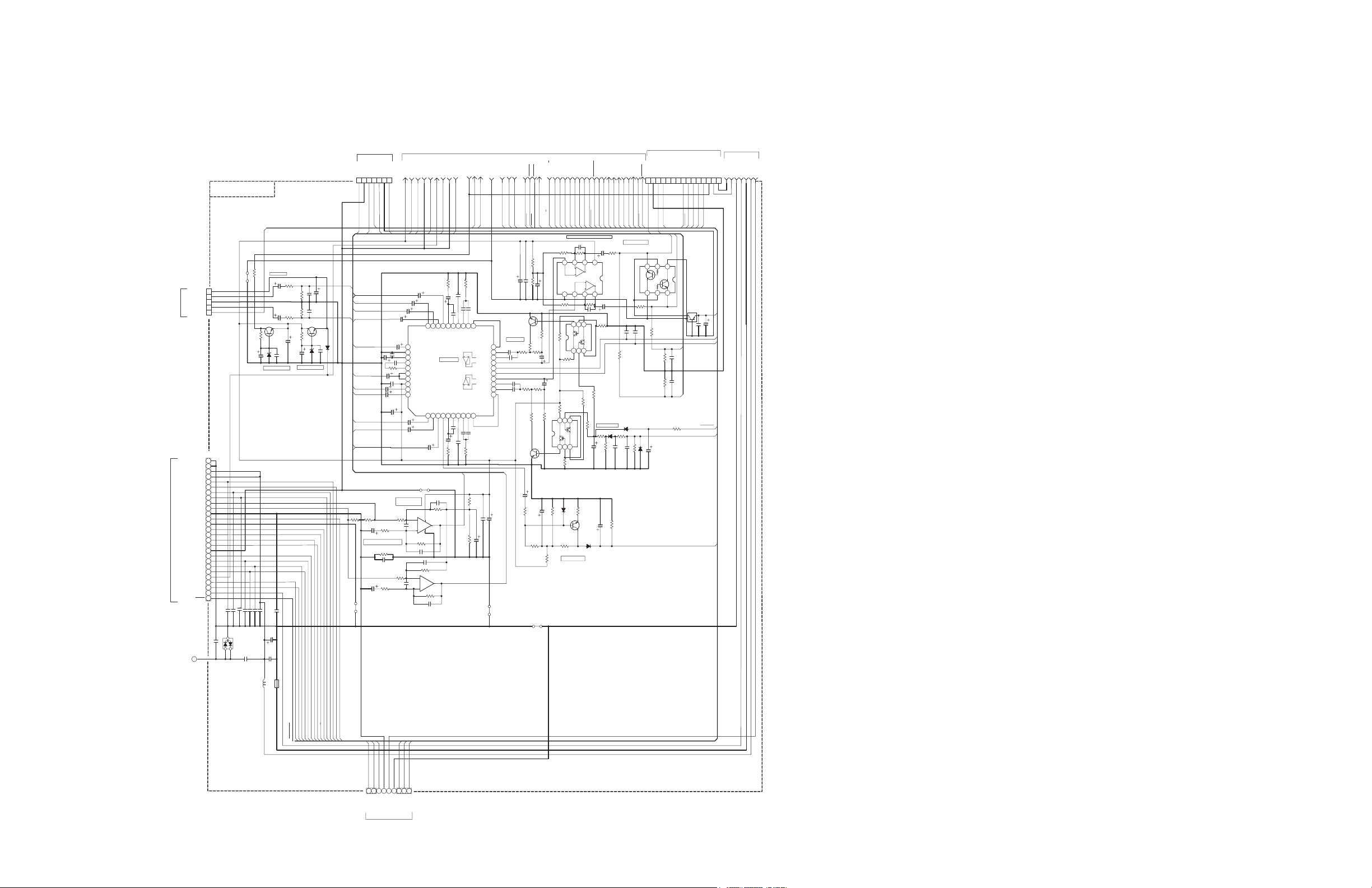
<Main section 3>
CN840
To Jack section
To Main section 2
CN600
To Power AMP section
To Main section 2
CN401
To iPod switch section
CN970
To iPod section
CN712
To DVD module section 2
created date:2010-02-02No.MB726
36
(No.MB726<Rev.001>)6/
Page 25

2.48
2.48
2.48
2.48
2.48
2.48
2.48
2.48
2.48
2.48
2.48
2.48
2.48
2.48
0
4.89
0
1.87
1.33
1.87
GVA10182-A6
1/2VCC
0
R4269
510R4254
510
R4263
1K
R4261
1K
R4253
1K
R4252
510
R4264
NIR4268
1K
R4272
10KR4255
1K
R4262
1K
R4251
0
R4275
510
R4273
1K
R4271
510
R4274
0
R4256
10K
R4267
47/10
C4261
47/10
C4262
47/10
C4271
47/10
C4251
47/10
C4252
47/10
C4272
47/10C4277
NI
C4256
0
C4259
10P/50C4254
NI
C4266
1/16C4276
10P/50
C4275
NI
C4258
NI
C4278
10P/50
C4265
NI
C4273
0
C4267
10P/50C4264
NI
C4263
NI
C4253
10P/50
C4274
0
C4257
10P/50
C4255
1
3
2
+
-
4
8
7
5
6
NJM2717M-X
IC420
+
-
7
5
6
+
-
4
8
1
3
2
NJM2717M-X
IC421
+
-
Cv/Pb_in 9
C/Py_in 8
Y/Pr_in 7
Audio_Return 6
5V 5
VGND 4
Cv/Pb_Out 3
C/Py_Out 2
Y/Pr_Out 1
QGA2001C1-09
CN401
<iPod switch section>
CN411/CN412
To Main section 3
created date:2010-02-02No.MB726
36
(No.MB726<Rev.001>)7/
Page 26

6.9V
3.2V
3.3V
0V
0V
3.3V
3.8V
0V
0V
2.7V
0.3V
3.32V
POWER
0V
STANDBY
0V
F+/F- REG
VARIO_BASS
KARA_sCORE
6.92V
3.31V
3.24V
C8303 ACTUALLY
2.76V
6.09V
F+
IS c8710
3.23V
0V
0V
EJECT
F-
GVA10182-A2
USB_REC
ECO/DEMO
0V
2 1
QSW1120-001Z
S8802
2 1
QSW1120-001Z
S8804
2 1
QSW1120-001Z
S8801
2 1
QSW1120-001Z
S8806
2 1
QSW1120-001Z
S8805
2 1
QSW1120-001Z
S8803
R8950
680
R8801
750
NI
R8504
R8806
18K
R8802
2K
R8804
4.3K
NI
R8503
R8805
8.2K
NI
R8502
R8803
2.7K
NI
Q8501
K8500
NI
F+1NC2NC3NC4NC5NC6NC7NC8NC9NC39NC40SI41CLK42LAT43BK44VDD45VH46PGND47LGND48F-
53
QLF0199-001
FL870
D8950
SLR-343VC-T
C8701
NI
C8704
NI
C8709
NI
10/50
C8711
C8710
0.1/16
C8700
NI
C8500
NI
C8702
1/50
C8703
NI
NI
B8500
B8501
B8507
F+ 13
F- 12
VDISP 11
FLGND 10
D6V 9
FL_CLK 8
FL_LATCH 7
FL_DAT 6
FL_BLANK 5
F_KEY1 4
LED_STBY 3
BGND 2
B3.3V 1
QGF1208F1-13
CN850
<Display section>
CN312
To Main section 2
created date:2010-02-02No.MB726
36
(No.MB726<Rev.001>)8/
Page 27

0V
0V
4V 28.3V
27.5V
27.5V
0V
0V
13V
0V
0V
0V
0V
3.31V
5.88V
0V
0V
0V
6.1V
0.82V
0V
AHB FB
2.0CH2.1CH2.2CH
LEFT-
RIGHT-
LEFT+
RIGHT+
RIGHT-
LEFT+
RIGHT+
LEFT-
S.WOOFER1-
S.WOOFER1+
S.WOOFER2-
S.WOOFER2+
S.WOOFER1-
S.WOOFER1+
RIGHT+
RIGHT-
LEFT+
LEFT-
QJJ028-041404-E
W6000
DC DETECTION
GVA10182-A3
(600KHz)
(700KHz)
+B
PGND
PGND
FAN_SP
0.84V
0V
27.8V
0V
27.9V
0V
-29.7V6V-29.7V
0V
0V
28.2V
-19.8V
10.8V
-29.9V
1.98V
1.94V
-29.9V
10.7V
28.4V
-20.9V0V-29.6V
0V
2.7V
2.6V
0V0V27.9V
0V
-28.5V
-28.5V
28.2V
12.9V
2.03V
-28.7V
-16.5V
-28.7V
2.03V
12.9V
28.2V
-20.4V
-28.5V
0V
27.8V0V0V
2.7V
0V
0V
3.3V
3.3V
0V
0V
0.2V
0V 0V
0V
0V0V
2.6V
2.6V
2.6V
2.4V
0V
5.2V
5.2V
0V
0V
4.8V
2.5V
2.4V
0V
5.2V
-29.8V
0V
0V
28.5V
R
L
1W
1W
1W
1W
LEVEL DETECTION
ERR
VDDP1
OUT12
OUT11
EP602
EP601
!
sure to use the specified one.
When replacing those parts make
Parts are safety assurance parts.!
QAX0936-001
X6502
QAX0937-001
X6501
3 4
12
QSK0194-001
RY620
34
1 2
QSK0194-001
RY621
1/4W
22
R6207
FR
39K
R6901
22
R6128
1.5K
R6224
4.7K
R6223
1W
10
R62191W10
R6220
22
R6028
R6807
NI
1W
10
R62171W10
R62181W10
R6216
NI
R6403
100K
R6702
NI
R6302NIR6301
NI
R6704
R6808
NI
NI
R6201
NI
R6202
10
R6103
5.6k
R6002
10
R6003
NI
R6214
5.6k
R6001
1W
1.5K
R6212
NI
R6211
5.6k
R6102
NI
R6210
5.6k
R6101
1W
1.5K
R6213
NI
R6428
NI
R6348
NI
R6099
NI
R6199
NI
R6399
NI
R6499
1M
R6504
100
R6505
22
R6501
1M
R6502
NI
R6400
10
R6100
1M
R6503
1K
R6705
NI
R6703
100
R6098
NI
R6398
10
R6203
10
R6204
39K
R6902
NI
R6401
10K
R6500
1.5K
R6506
1.5K
R6507
1W
10
R6215
100K
R6706
NI
R6303
1W
120
R6206
1W
120
R6205
R6805
39K
R6809
12K
R6806
39K
100K
R6701
NI
R6402
KRC102S-X
Q6500
KRA101S-X
Q6220
2SC3928A/RS/-X
Q6200
NI
Q6210
2
4 3
1
NI
L6073
2
4 3
1
NI
L6071
2
4 3
1
NI
L6070
2
4 3
1
NI
L6072
NI
L6401
QQR1820-001
L6001
QQR1820-001
L6101
NI
L6301
QQL244K-220Z
L6502
QQR0621-001Z
K6202
QQR0621-001Z
K6201
NQR0502-001X
K6502
QQR0621-001Z
K6501
OSC1IN1P2IN1M3VDDA14SGND15VSSA16PROT7VDDP18BOOT19OUT110VSSP111STABI12VSSP213OUT214BOOT215VDDP216VSSD17VSSA218SGND219VDDA220MODE23IN2P22IN2M
21
NI
TDA8920CJ/N1
IC630
OSC1IN1P2IN1M3VDDA14SGND15VSSA16PROT7VDDP18BOOT19OUT110VSSP111STABI12VSSP213OUT214BOOT215VDDP216VSSD17VSSA218SGND219VDDA220MODE23IN2P22IN2M
21
TDA8920CJ/N1
IC610
1A
1
1Y
2
2A
3
2Y
4
3A
5
3Y
6
GND74Y
8
4A
9
5Y
10
5A
11
6Y
12
6A
13
VCC
14
74HCU04PW-X
IC650
6 5 4
321
RT3CLLM/EF/-X
IC670
4
3
2
1
QUM024-14DGZ4-E
FW601
3
1
2
MC2838-X
D6801
1
3
2
MC2838-X
D6901
MA8039-X
D6803
3.6B
D6220
NI
D6210
NI
D6215
D6804
NI
D6802
NI
15B
D6221
MA111-X
D6098
NI
D6912
MA111-X
D6222
MA111-X
D6501
MA111-X
D6502
NI
D6911
MA111-X
D6000
MA111-X
D6701
GS1J-X
D6200
NI
D6398
CP
CP620
ICP-N50-T
10/50
C6098
C6805
10/50
NI
C6206
47/100
C6013
470/35
C6208
470/35
C6207
QUY158-050Y
C6902
QUY158-050Y
C6901
NI
C6313
4700/35
C6204
10/50
C6701
4700/35
C6203
NI
C6205
100/50
C6510
NI
C6398
NI
C6104
100P
C6506
100P
C6505
100P
C6504
100P
C6503
0.01
C6502
0.01
C6501
NI
C6304NIC6305
NI
C6124
0.1
C6509
0.1
C6128
NI
C6024
NI
C6324
NI
C6312
NI
C6403
0.1
C6202
0.1
C6201
NI
C6401
47P
C6507
NI
C6327
NI
C6428
NI
C6328
NI
C6402
47P
C6508
0.1
C6028
NI
C6427
NI
C6004
0.47
C6103
NI
C6410
0.47
C6102
NI
C6307
NI
C6309
0.1/16
C6005
0.1
C6010
0.015
C6009
10p
C6008
0.47
C6015
0.1/50
C6081
0.1
C6210
0.1
C6106
0.47
C6002
0.015
C6109
220p
C6114
0.47
C6003
0.1
C6011
0.1
C6107
0.1
C6112
0.1/50
C6070
NI
C6974
0.1
C6012
NI
C6215
220p
C6101
NI
C6006
0.1
C6111
NI
C6007
220p
C6014
NI
C6216
0.1
C6110
NI
C6072
220p
C6001
0.1
C6209
NI
C6083
0.1/50
C6071
0.1/16
C6084
NI
C6085
0.1/50
C6217
NI
C6409
NI
C6311
NI
C6073
NI
C6406
NI
C6407
NI
C6412
0.68
C6127
0.1/50
C6218
NI
C6315
NI
C69710C6972
NI
C6303
NI
C6310
NI
C6411
NI
C6973
0.68
C6027
220p
C6016
0.1/50
C6080
NI
C6314
0
C6082
NI
C6301
NI
C6302
220p
C6116
NI
C6414
0.1
C6211
NI
C6308
NI
C6316
NI
C6306
NI
C6416
NI
B6201
B6170
NI
B6177
B6107
NI
B6028
B6171
B6173
NI
B6026
B6302
B6172
NI
B6174
NI
B6175
NI
B6176
NI
B6012
NI
B6011
1
NI
PP603
1
NI
PP601
1
NI
PP602
DGND 1
D6V 2
A13V 3
AMP_RY 4
AMP_BEAT 5
LEV_DET 6
DC DET 7
MODE 8
SWAHB_FB 9
SW_IN 10
SWGND 11
AHB_FB 12
RIN 13
MAINGND 14
LIN 15
QGF1208F1-15
CN600
9
10
8
7
6
5
4
3
2
1
QNB0315-003
J6100
-B 4
PGND 3
PGND 2
+B 1
QGA3901C1-04
CN601
<Power AMP section>
CN181
To Main section 1
CN2
To POWER UNIT
To SPEAKER
CN503
To Main section 3
created date:2010-02-02No.MB726
36
(No.MB726<Rev.001>)9/
Page 28

0V
0V
0V
0V
0V
AUX IN
0V
0V
0V
USB A
0V
0V
HP
0V
0V
GVA10182-A4
180K
R8403
10K
R8301
4.7K
R8452
180K
R8404
10K
R8300
4.7K
R8451
K8304
NQR0502-001X
NQR0502-001X
K8450
K8451
0
K8400
0
K8300
NQR0502-001X
K8452
0
NQR0502-001X
K8402
K8320
NQR0022-003X
K8301
NQR0022-003X
K8401
0
STZC6.8N-X
D8301
NI
D8300
MA111-X
D8451
MA111-X
D8450
MA111-X
D8400
MA111-X
D8401
NI
D8302
NI
D8303
C8452
NI
C8405
NI
C8403
0.1/50
C8404
NI
C8302
NI
C8402
0.1/50
C8401
0.01/50
C8400
0.1/16
C8450
0.1/16
NI
C8304
C8301
NI
C8453
NI
C8303
0.1/16
C8300
1800P/50
NI
B8304
NI
B8320
NI
B8403
NI
B8300
NI
B8301
NI
B8404
7
5
3
1
4
6
2
QNS0289-001
J8401
7
5
6
1
4
3
2
QNS0289-001
J8400
1
NI
W8400
1
NI
W8301
HPR7
HPGND6
HPL5
HPSW4
AUXL3
AUX_GND2
AUXR1
QGF1208F1-07
CN840
5V5
D-4
D+3
GND2
GND1
WJP0094-013A-E
W8300
5 6
GND 4
D+ 3
D- 2
5V 1
QNZ0906-001
J8300
<Jack section>
CN502
To Main section 3
CN811
To DVD section 3
created date:2010-02-02No.MB726
36
(No.MB726<Rev.001>)10/
Page 29

9.6V
4.7V
4.8V
0V
4.8V
4.8V
4.8V
4.8V
3.3V
2.4V
2.4V
0.6V
2.4V
2.4V
3.3V
0V
0.6V
2.4V
2.4V
2.4V
1.2V
2.4V
2.4V
0V
2.4V
2.4V
2.4V
2.4V
2.4V
2.4V
2.4V
2.4V
2.4V
4.8V
2.4V
4.8V
1.6V
2.4V
2.4V
2.4V
0V0V0V
0V
9.56V
4.78V
MIC2 MIC1
GVA10182-A5
MIC AMP & MIC CAL
0V
0V
3.31V
4.76V
3.32V
NI
R8031
15K
R8022
4.7K
R8001
2.2M
R8005
15K
R8017
10K
R8004
15K
R8003
15K
R8020
30K
R8019
10K
R8025
15K
R8021
SHORT
R8002
24K
R8013
4.7K
R8009
10KR8006
91K
R8024
100K
R8011
4.7K
R8000
4.7K
R8014
10K
R8023
51K
R8012
4.7K
R8008
30K
R8018
15K
R8015
100K
R8007
47K
R8030
100K
R8010
15K
R8016
QQR0621-001Z
SHORT
K8002
QQR0621-001Z
K8003
NI
K8000
NQR0502-001X
NQR0502-001X
K8001
VREF
1
VCC
2
ALC_TC
3
ALC_LC
4
MIC_IN
5
MIC_NFIN
6
MIC_OUT
7
MICVOL_IN
8
MIX_OUT
9
LPF1_IN
10
LPF1_OUT
11
TEST
12
FLAG_OUT
13
MCLK
14
LIN
15
RIN
16
BPF1
17
BPF2
18
SDA
19
SCL
20
AGND
21
OP1_IN
22
OP1_OUT
23
CC1
24
CC2
25
OP2_IN
26
OP2_OUT
27
LPF2_IN
28
LPF2_OUT
29
ECHOVOL_IN
30
MIX_NFIN
31
MIX_OUT
32
R2A15907SP-X
IC801
123
AGND
4
A9V
8765
NJM4565E-X
IC800
MA8039-X
D8001
MA111-X
D8003
MA111-X
D8000
MA111-X
D8004
MA111-X
D8002
1/50
C8020
10/50
C8034
4.7/50
C8014
1/50
C8006
100/16
C8000
100/16
C8003
C8038
100/16
10/50
C8004
100P
C8016
1/16
C8007
1/16
C8023
0.033/50
C8012
3300P
C8025
C8010
0.1/50
0.1/16
C8026
0.1
C8032
NI
C8030
0.1/16
C8021
1/16
C8005
0.01/50
C8013
NI
C8031
1/16
C8002
1000P
C8008
0.1/16
C8029
1/16
C8011
1500p
C8033
10P/50
C8035
0..22/16
C8015
3300P
C8019
680P
C8024
0.1/16
C8028
1/16
C8001
1000P
C8009
C8040
0.1/16
1/6.3
C8017
C8037
0.1/16
0.1/16
C8027
680P
C8018
0.001/50C8036
C8039
0.01/16
3
1
4
2
QNS0292-001
J8000
3
1
4
2
QNS0292-001
J8001
1
NI
W8000
MIC_DAT 11
MIC_FLAG 10
MIC_CLK 9
MIC_CAL 8
MIC_DET 7
A5.5V 6
RECR 5
AGND 4
RECL 3
A9V 2
MIC_SIG 1
QGF1208F1-11
CN800
<Mic section>
CN304
To Main section 2
created date:2010-02-02No.MB726
36
(No.MB726<Rev.001>)11/
Page 30

6.1V
MOTION SENSOR
3.32V
VDD
5.41V
C9851 actually C8851
GND
OUT
3.2V
REMOTE CONTROL
3.3V
0V
GND
GVA10182-A7
3.28V
GND
0V
0V
0V
R8900
1.8K
R8901
NI
54321
GP1UE261RKC1
IC880
D8900
SIR-34STA49-T
C8851
0.1/16
C8850
NI
B3.3V5
BGND4
REM3
M_LED2
D6V1
QUM025-11DGZ4-E
FW315
<Sensor section>
CN315
To Main section 2
created date:2010-02-02No.MB726
36
(No.MB726<Rev.001>)12/
Page 31

0.8V
0V
0V
0.8V
0V
0V
0V
3.3V
0V
3.1V
3.1V
3.1V
1.3V
1.6V
1.6V
0V
1.5V
1.6V
1.6V
0V
3.3V
1.6V
1.5V
1V
1.1V
2.4V
1.1V
0V
3.3V
3.1V
1.6V
1.6V
1.5V
1.6V
0V
3.1V
3.1V
2.4V
1.1V
Vol_1
SOURCE-
FF
Vol_6
3.31V
STOP
2.55V
PLAY/PAUSE
Vol_8
0V
0V
9.22V
Vol_3
FW
Vol_5
MIC LEVEL
0V
Vol_7
3.32V0V2.58V
Vol_2
SOURCE+
SUBWOOFER
Vol_4
0V
0V
0V
3.06V
3.06V
GVA10183-A1
3.06V
3.06V
PGD
PGC
VSS
VDD
MCLR
0
R9508
10k
R9104
150
R9002
1k
R9101
0
R9514
0
R9509
100
R9106
0
R9512
0
R95050R9507
0
R9515
0
R9511
0
R9500
1k
R9110
0
R9502
0
R9513
10K
R9105
NI
R9009
150
R9005
10K
R9102
0
R9504
0
R9510
1k
R9103
NI
R9008
150
R9006
0
R9503
0
R9506
1k
R9111
150
R9004
150
R9007
150
R9003
0
R9501
150
R9001
0
K9101
0
K9102
0
K9104
0
K9103
RC644
RC543
SDA/RC442
CPS11/RD341
CPS10/RD240
CPS9/RD139
CPS8/RD038
SCL/RC337
RC236
RC135
NC34
NC
33
RC0
32
RA6/VCAP
31
RA7
30
VSS
29
VDD
28
RE2
27
RE1
26
RE0
25
CPS7/RA5
24
CPS6/RA4
23
RA3 22
RA2 21
RA1 20
VCAP/RA0 19
MCLR/RE3 18
DATA/RB7 17
CLK/RB6 16
CPS5/RB5 15
CPS4/RB4 14
NC 13
NC 12
CPS3/RB3
11
CPS2/RB2
10
CPS1/RB1
9
CPS0/RB0
8
VDD
7
VSS
6
CPS15/RD7
5
CPS14/RD6
4
CPS13/RD5
3
CPS12/RD4
2
RC7
1
PIC16F724
IC901
6 5 4
321
KTC801U/G/-X
IC902
D9002
D9001
D9006
D9008
D9011
D9003
D9012
D9009
D9004
D9007
D9010
D9005
NI
C9506
NI
C9502
NI
C9513
NI
C9509
NI
C9504
NI
C9501
NI
C9514
NI
C9511
NI
C9512
NI
C9500
NI
C9515
NI
C9505
NI
C9503
1/16
C9001
NI
C9507
1/16
C9003
1/16
C9002
NI
C9510
NI
C9508
PGC 9
PGD 8
MCLR 7
SDA/TXD 6
SCL 5
M9V 4
3.3V 3
BGND 2
MGND 1
QGF1016C6-09W
CN900
M9V7
DIMMER6
MGND5
VOL_LED44
VOL_LED33
VOL_LED22
VOL_LED11
QGF1016C6-07W
CN901
<Touch section>
CN920
To LED illum section
CN301
To Main section 2
created date:2010-02-02No.MB726
36
(No.MB726<Rev.001>)13/
Page 32

0V4V
0V 4V
0V0V
4V
0V
0V0V
4V
0V
0V
0V
4V
0V
0V
3.1V
9.2V
3.1V
3.1V
3.1V
GVA10177-A2
LED D9200~D9007:SELT1E54CM-S or NSSW020B-P1-X
NI
R9214
180
R9203
1K
R9210
NI
R9213
NI
R9215
NI
R9202
180
R9204
180
R9205
1K
R9200
1K
R9216
1K
R9219
1K
R9218
1K
R9208
180
R9206
1K
R9212
1K
R9217
KRC110S-X
Q9201
654
3 2 1
KTC801U/G/-X
IC921
654
3 2 1
KTC801U/G/-X
IC920
D9207 D9203
D9205
D9202
D9201
D9200D9204
D9206
NI
C9201
NI
C9200
NI
C9203
NI
C9202
M9V 1
DIMMER 2
MGND 3
VOL_LED4 4
VOL_LED3 5
VOL_LED2 6
VOL_LED1 7
QGF1016C6-07W
CN920
<LED Illumination section>
CN901
To Touch section
created date:2010-02-02No.MB726
36
(No.MB726<Rev.001>)14/
Page 33

3.3V
3.3V
0V
0V
3.3V
3.3V
0V
4.81V
0V
2.62V
0V
0V
1.97V
2.62V
2.77V
1.92V
0V
1.14V
1.87V
0V
1.87V
0V
2.77V
2.77V
0V
0V
0V
0V
4.8V
2.7V
2.7V
2.9V
2.9V
0V
0V
0V
2.9V
1.4V
2.9V
1.4V
2.9V
2.9V
6.1V
3.3V
0V
5V
3.4V
6.1V
3.3V3.4V
0V
5V
0V
2.03V
5V
0V
2.02V
0V
0V
0V
0V
0V
0V
0V
0V
0V
0V
0V
0V
3.3V
0V
0V
3.3V
0V
0V
0V
0V
0V
0V
0V
0V
0V
0V
0V
0V
0V
0V
2.02V
0V
0V
2.03V
5V
6.1V
3.3V
3.3V
4.8V
3.3V
0V
3.3V
3.3V
0V
1.13V
1.86V
1.86V
3.3V
0V
3.3V
0V
2.9V
2.9V
0V
0V
0V
1.15V
3.3V
6.1V
0V
0V
0V
THERMAL PADTHERMAL PAD
CLK
VOUT
IPOD VIDEO SW
3.3V
VSS
IPOD AUDIO SW
GVA10183-A1
DATA
RESET
33
CN990
33
CN980
560K
R9905
27K
R7801
75K
R9904
NI
R9700
10K
R9704
75K
R9903
NI
R9711
NI
R9710
51K
R9902
10K
R9705
51K
R9802
0
R9706
NI
R9823NIR9822NIR9821
NI
R9923
NI
R9922
NI
R9921
NI
R9701
NI
R9702
NI
R9752
51K
R9901
10K
R9703
560K
R9805
22K
R9731
75K
R9803
75K
R9804
NI
R9751
51K
R9801
10K
R9741
10K
R9906
10K
R9806
1k
R9730
KRC102S-X
Q9741
KRC102S-X
Q9731
KRC102S-X
Q7802
KRA102S-X
Q7801
S
G
D
RSR025P03-X
Q7804
S
G
D
RSR025P03-X
Q7803
NQR0502-002X
K9825
NQR0502-002X
K9820
K9929
SHORT
K9922
K9828
NQR0502-002X
K9824
SHORT
K9923
SHORT
K9823
K9927
K9919
K9818
SHORT
K9921
K9829
K9918
K9813
K9808
K9801
K9908
K9930
K9827
SHORT
K9821
K9928
NQR0502-002X
K9700
K9830
SHORT
K9822
K9819
NQR0502-002X
K9701
K9901
K9913
201918
17
16
15 14 13 12 11
10
987
6
54321
MFI341S2164-X
IC970
PrIN1
16
GND
15
PrIN21CTLA2PrOUT3GND4PbOUT5PyOUT6CTLC
7
PbIN2
14
VCC
13
CTLB
12
PbIN1
11
GND
10
PyIN2
9
PyIN1
8
MM1732XV-X
IC971
1 2 3 4 5 6
VSS
7
8910111213
VDD
14
TC4066BFT-X
IC972
NRSA63J-0R0X
D7801
NI
C9763
NI
C9715
NI
C9753
0.01/16
C7801
1/16
C9741
1/16
C9731
NI
C9800
C9761
1/16
C9751
NI
C9807
0.1/50
C9801
100P
C9902
100P
C9803
470P
C9754
1/16
C9721
NI
C9905
1/16
C9742
NI
C9702
1/16
C9732
NI
C9806
NI
C9700
NI
C9716
1/16
C9701
1/16
C9714
100P
C9802
NI
C9717
NI
C9805
0.1/50
C9901
100P
C9804
NI
C9703
1/16
C9722
1/16
C9712
NI
C9733
NI
C9906
1/16
C9723
100P
C9904
NI
C9900
1/16
C9762
NI
C9907
1/16
C9713
1/16
C9711
100P
C9903
470P
C9764
1/16
C9752
NI
B9900
NI
B9800
9
CN
4
GND
3
NC
2
VO
1
CONT
5
NC
6
NC
7
VIN
8
MM1665AH-X
IC974
9
CN
4
GND
3
NC
2
VO
1
CONT
5
NC
6
NC
7
VIN
8
MM1665AH-X
IC973
IPOD_DET 30
AV_RETURN 29
LINE-OUT_R 28
LINE-OUT_L 27
LINE-IN_R 26
LINE-IN_L 25
REMOTE_SENSE 24
CV/Pb 23
SC/Y 22
SY/Pr 21
ACC_DET 20
TX 19
RX 18
RESERVED 17
DGND 16
DGND 15
RESERVED 14
ACC_PWR 13
FW_PWR+ 12
FW_PWR+ 11
ACC_IDENTIFY 10
TPB- 9
USB_VBUS 8
TPB+ 7
USB_D- 6
TPA- 5
USB_D+ 4
TPA+ 3
DGND 2
DGND 1
NNZ0186-001
CN980
IPOD_DET 30
AV_RETURN 29
LINE-OUT_R 28
LINE-OUT_L 27
LINE-IN_R 26
LINE-IN_L 25
REMOTE_SENSE 24
CV/Pb 23
SC/Y 22
SY/Pr 21
ACC_DET 20
TX 19
RX 18
RESERVED 17
DGND 16
DGND 15
RESERVED 14
ACC_PWR 13
FW_PWR+ 12
FW_PWR+ 11
ACC_IDENTIFY 10
TPB- 9
USB_VBUS 8
TPB+ 7
USB_D- 6
TPA- 5
USB_D+ 4
TPA+ 3
DGND 2
DGND 1
NNZ0186-001
CN990
RESET27
B3.3V26
CLK25
DATA24
A5V23
IPODB_DET22
IPODB_PWR21
IPODB_TX20
IPODB_RX19
AGND18
C/Py17
Y/Pr16
CV/Pb15
IPOD_A/B14
VGND13
F_IPOD12
AUDIO_RETURN11
OUTR10
OUTL9
IPODA_PWR8
IPODA_DET7
IPODA_RX6
IPODA_TX5
D6V4
D6V3
DGND2
DGND1
QGF1016F8-27W
CN970
STAR 2
CHASS 1
QGA2001F6-02X
CN781
<iPod section>
CN400
To Main section 3
DOCK-A
To iPod
DOCK-B
To iPod
created date:2010-02-02No.MB726
36
(No.MB726<Rev.001>)15/
Page 34

2SC4617R/-X
OR
2SC4617R/-X
OR
1/4WOR
(C)
(D)
(B)
(A)
(C)
(D)
(B)
(A)
F-
,
ALL RESISTANCE VALUES ARE
ARE IN H(m=mH).
6.3V
in
.
25V
OR
1.
,
OF
CERAMIC CAPACITOR
.
±
VOLTAGES ARE DC-MEASURED WITH A DIGITAL
disc theμandDVD
METAL GLAZE RESISTOR.
UNLESS OTHERWISE SPECIFIED.
F(p=pF).
or
ALL INDUCTANCE VALUES
5%
A
ALL E.CAPACITORS ARE SHOWN IN THE FORM
NI STANDS FOR NOT INSERTED PARTS.
/RATED VOLTAGE (V).
mode1
ALL CAPACITANCE VALUES ARE IN
NOTES
16V
μ
CAPACITANCE( F)
50V
3.
CONDITION ---
Ω
2.
μ
METAL GLAZE RESISTOR.1/16W
10V
0.5%
STOP
,
Tray
ALL CAPACITORS ARE
WITHOUT INPUT SIGNAL.
,
IN OHM( ).
VOLT METER
ALL RESISTORS ARE
(ADCPDN)
(USB_PHY+)
(USB_PHY-)
SDRAM
(REF_MODE_SET)
(14/15=L:H=64M)
(H:L=USB:ADAC)
(H:L=MULTI:SEPA)
H
G
F
E
D
C
B
(RX)
(for HDMI)
(DISCSET)
(DAC0CS)
(NOC)
(NEN)
/INH
XT /XT
VDD VSS
Qo
48MHz
OSC
Cn
0VNC
Sub0V
REG.
Vout
Cont
GND
Vin
3.9V
3.3V
1.9V
4.0V
3.3V
REG.
3.9V
D1.2V
0V
0V
0V
1.2V
(VCLKO)
(DDATA)
VS
PICKUP
PD(DVD)
FXL-D10-1M
PD(CD)
D
TRVSW
VR(CD)
F+
MOTOR
LD(CD)
QAR0165-001
FEED
UOUT
WOUT
GND
F
+RF
NC
VCC
ASS'Y
SWGND
LD(DVD)
GND
T-
QAR0386-001
MOTOR
QAL0786-***
VCC(HF)
E
TRA
C
A
MECHA
FM-
(OPA-652PH*)
T+
VOUT
FM+
ASS'Y
VR(DVD)
SPINDLE
COM
B
GND
LVA10824-671A (1/3)
(ADIN)
(AOUT2)
(AOUT1)
(AOUT0)
(DAC2CS)
(DAC1CS)
(DACPDN)
(UCLK)
(SCK)
(UCS)
(SDA)
(SPDRV)
(TRVSW)
(TRSDRV)
(SPMUTE)
(MONI6)
(MONI2)
(MONI7)
(MONI3)
(MONI4)
(MONI0)
(MONI5)
(MONI1)
(TRACK)
(COPY)
(DEMP)
(DISCSTP)
(INDEX)
(U2SDT)
(SCS)
(48MHz)
(DCLK)
(S2UDT)
(LRMUTE/TDATA)
27MHz
DRIVER
or
CHASSIS
TRDRV
AMP3IN+
OUT2R
AMP4IN+
BR
0V
NC
9V
AMPIN-
DV5
or
NC
OUT4R
MUTE2
AMPIN+
SPC2
MGND
KTA1001/Y/-X
0V
0V
AMP1IN+
KTA1001/Y/-X
TRSDRV
SPDRV
FODRV
VHALF2
SPCTL
VCC1
NC
MGND
AMP3IN-
AMP2IN+
LASER
EEPROM
SCLK
MGND
SPCX
DRIVER
OUT2F
SPVCOIN
AMP4IN-
SGND
F
RESET
0V
TEMPDET
0V
FR
0V
VREF
MGND
MUTE3
VOUT
SPFGO
AMP2IN-
OUT1R
0V
WOUT
AMPOUT
OUT4F
MECHA
VCC2
MUTE1
VCC
SPFC
for ICE
OUT1F0VOUT3R
DGND
AMP2OUT
0V
MCOM
AMP1OUT
SDATA
0V
AMP3OUT
9V
UOUT
SPRF
AMP1IN-
DGND
SPC1
0V
OUT3F
EXDT1
EXDT9
EXDT2
EXDT10
DAC2CS
DVDLDCUR
VREFH
E
F
D
A
B
C
RF+
LPC2
LPC1
LPC2
LPC1
T-
T+
F-
F+
VREFH
TRVSW
ADIN
F
E
ADCPDN
EXADT11
SPDRV
EXADT13
RX
DVDPWR
TX
CPURST
AOUT0
AOUT1
AOUT2
LRMUTE
SPMUTE
ROUT
LOUT
DACCK
BCKM
BCK
LRCKM
LRCK
DATAM
DACPDNDACPDN
NOC
NEN
DAC0CS
SDA
SCK
SDA
SCK
DP
DM
DVDPWR
EXADR20
DAC1CS
EXADT1
DEMP
SPDRV
COPY
EXADR16
EXADT15
EXADT14
EXADT12
EXADR18
DDATA
DCLK
CPURST
FG
INDEX
TRACK
C
A
UCS
UCLK
S2UDT
SCS
U2SDT
TRDRV
FODRV
MCK
TRVSW
DVDLDCUR
EXDT12
EXDT5
AD4
MDQ15
MCK
EXDT13
EXDT6
MDQ7
MDQ11
EXDT0
EXDT8
MA2
MA5
MA1
NCSM
NRAS
LPCO2
LPCO1
FG
EXADT3
EXADT2
EXADT0
EXDT15
UOUT
EXDT7
DAC3OUT
DQM1
DQM0
WOUT
EXADT10
MDQ8
EXDT14
COM
NEXCE
MDQ6
TRSDRV
FM+
TRDRV
NEXOE
MDQ9
FM-
B
DAC2OUT
RF+
D
MA8
DAC1OUT
MA3
SPMUTE
BA1
DAC4OUT
MA4
NEXWE
VOUT
MA9
DAC5OUT
MA6
EXADR19
FM-
F+
BA0
MA0
EXDT4
EXADT8
LPCO2
MA11
MA7
EXDT11
EXADT9
MDQ3
MDQ5
NCAS
AD4
MDQ12LPCO1
MDQ10
NWE
MA10
MDQ2
MDQ14
MDQ13
MDQ1
VOUT
MDQ0
MDQ4
EXDT3
EXADR17
UOUT
EXADT7
COM
CDLDCUR
EXADT6
T-
WOUT
EXADT5
FODRV
EXADT4
CDLDCUR
TRSDRV
T+
F-
FM+
S5V
S5V
D2V
P3.3V
D1.2V
M5V
S3.3V
D4V
M9V
AGND
MGND
DGND
NAX0741-001X
X301
NAX0376-002X
X302
TP208
TP119
TP117
TP206
TP226
TP333
TP116
TP331
TP326
TP109
TP108
TP381
TP202
TP231
TP204
TP110
TP327
TP329
TP316
TP118TP205
TP103
TP322
TP332
TP315
TP338
TP105
TP334
TP337
TP201
TP221
TP104
TP121
TP227
TP203
TP292
TP291
TP328
TP107
TP115
TP111
TP120
TP101
TP207
TP330
TP324
TP106
TP112
TP321
TP220
TP122
TP123
TP102
TP323
NAD0025-103X
TH301
TP303
TP302
TP300
TP301
0R317
R326
10k
NIR702
NIR703
R334 150
R337 150
R348 150
R338 0
R221
6.8k
NIR321
R375
470
R325 330
R376 1k
R368
NI
R369
NI
R316 1k
R201
470
1%
R340
30k
R359 NI
R358 220
R331
NI
R330
NI
R329
NI
R328
NI
NIR322
R361
10k
R111
5.6k
R117
330
R220
24k
R362 47
R204
27k
R104
4.3k
R207
47k
1/4W
R105
18
R115
1k
R364 NI
R347
20k
R398
NI
R118
NI
R257 NI
R323 330
1/4W
R113
18
R308 NI
R353 100
R360
NI
R392
10k
R541 4.7k
R310
100
1/2W
R251
0.39
R206
30k
R333 330
R351 330
R127
4.3k
R108
470
0R705
R290
0
R384
1k
R365 NI
R309 100k
R107
1k
R346
22k
R343 NI
R112
4.3k
R110
NI
R259 10k
R214
10k
R349 NI
R373 10k
R339 0
R102 100
R307 1k
R304 4.3k
R109
330
R318 22
R291
0
R213
10k
R335
150
R128
5.6k
R125
1
R350 NI
R306 1k
R219
18k
R116
470
NIR370
R371
10k
0
R314
R129
NI
R324 330
R101 100
R332 NI
R393
NI
R357
220
R352 1M
R367 220
R103
5.6k
R344 NI
R394 NI
R395 NI
R385
1k
R397 NI
1%
R341
5.1k
R372 10k
R363
NI
R366 NI
R205
27k
R303
22
R311 330
R336 150
R396 NI
R378 NI
R202
1k
R379 NI
R383 100
NIR315
NIR319
NIR320
4.7
R131
0R704
NIR312
R313
NI
R345 220
R106
2.2
R114
2.2
R130 NI
R132 NI
1%
R342
2.2k
2SC5383/E/-X
Q104
2SC5383/E/-X
Q102
2SA1363/EF/-X
Q103
2SA1363/EF/-X
Q101
L301
NI
NQR0502-001X
K353
NQR0022-002X
K354
NQR0502-001X
K352
NQR0502-001X
K101
216EXDT8
215EXDT0
214NEXOE
213NEXCE
212EXADT0
211VDD12
210VSS
209MA3
208MA4
207MA2
206MA5
205VDD33
204VSS
203MA1
202MA6
201MA0
200MA7
199MA10
198MA8
197BA1
196VDD33
195VSS
194MA9
193BA0
192DQM3
191DQM2
190NCSM
189NRAS
188NCAS
187VDD12
186VSS
185MCKI
184VDD33
183MCK
182VSS
181NWE
180DQM1
179DQM0
178MDQ7
177MDQ8
176MDQ6
175MDQ9
174VDD33
173VSS
172MDQ5
171MDQ10
170MDQ4
169MDQ11
168MDQ3
167MDQ12
166VDD33
165VSS
164MDQ2
163MDQ13
162
MDQ1
161
MDQ14
160
MDQ0
159
MDQ15
158
VDD12
157
VSS
156
OSCO
155
OSCI
154
VDD33
153
VSS
152
IECOUT
151
ADOUT
150
LRCK
149
SRCK
148
DACCK
147
AVDDI
146
ROUT
145
AVSSI
144
LOUT
143
AVSSG
142
AVDDG
141
AVDDE
140
AVSSE
139
DAC5OUT
138
DAC4OUT
137
AVSSF
136
COMP2
135
IREF1
134
VREF
133
COMP1
132
AVDDF
131
DAC1OUT
130
DAC2OUT
129
DAC3OUT
128
AVDDH
127
PWM0
126
PWM1
125
AVSSH
124
AD4
123
AD2
122
AD1
121
AD0
120
VIN1
119
VIN2
118
VIN4
117
VIN3
116
VIN8
115
VIN7
114
VIN6
113
VIN5
112
VIN9
111
VIN10
110
VHALF
109
VREFH
108 AVSSB
107 AVDDB
106 LPCO2
105 LPC2
104 LPCO1
103 LPC1
102 VREFL5
101 VREFH5
100 VIN3RF
99 VIN4RF
98 VIN2RF
97 VIN1RF
96 RFINP
95 RFINN
94 ANAMONI2
93 ANAMONI1
92 AVDDC
91 CDATA
90 CCAPA
89 AVSSC
88 VREFL7
87 AVSSD
86 VREFH7
85 PLFIL1
84 AVDDD
83 VDD12
82 VSS
81 TRCST
80 TRVDATA3
79 TRCDATA2
78 TRCDATA1
77 TRCDATA0
76 TRCCLK
75 EXTRG1
74 EXTRG0
73 SDATA
72 SCLOCK
71 FG
70 NRST
69 VDD33
68 VSS
67 DRV0
66 DRV1
65 DRV2
64 DRV3
63 DRV4
62 DRV5
61 P14
60 P13
59 P12
58 S3CLK
57 S3OUT
56 P9
55 S2CLK
54
S2OUT
53
S2IN
52
VDD33
51
VSS
50P549
S1OUT
48
INT0
47
S0CLK46S0OUT
45
EXADR20
44
VDD12
43
VSS
42
EXADT141EXADT240EXADT339EXADT438EXADT537EXADT636EXADT7
35
EXADR1734EXADR18
33
VDD33
32
VSS
31
NEXWE
30
EXADR19
29
EXADT828EXADT9
27
EXADT1026EXADT1125EXADT1224EXADT1323EXADT1422EXADT1521EXADR16
20
VDD12
19
VSS
18
EXDT15
17
EXDT716VDD33
15
VSS
14
EXDT14
13
EXDT6
12
EXDT13
11
EXDT5
10
EXDT12
9
EXDT4
8
EXDT11
7
EXDT36VDD33
5
VSS
4
EXDT10
3
EXDT22EXDT91EXDT1
MN2DS0018MA
IC301
48474645444342414039383750363534333231302928272625
24 23 22 21 20 19 18 17 16 15 14 13 49 12 11 10 9 8 7 6 5 4 3 2 1
LA6502-X
IC201
A0
1
A1
2
A2
3
GND4SDA
5
SCL
6
WP
7
VCC
8
S-24CS16A0I-G-X
IC510
765
4 3 2 1
NI
IC304
654
3 2 1
XC2164A51FM-X
IC303
MA2SD31-X
D301
220/6.3
C391
C263
100/16
C303 47/4
T
C339
10/6.3
C302
47/4
C105
47/6.3
C264
NI
T
C106
22/6.3
C301
220/6.3
T
C108
22/6.3
C336 NI
C374
0.1
C331 0.033
C314 0.1
C321 0.1
C305
0.1
NI
C344
C204
0.1
C206
150p
C309
0.1
C349
0.1
C377
NI
C205
270p
C393
0.01
C356
1
C258 0.015
C202
220p
C310
0.1
F
C210
1
C306
0.1
C373
0.1
C217
0.1
C201
220p
C348 0.1
C337
0.018
C353
560p
C102
0.1
C313
0.1
C262 0.022
C307
0.1
C383
0.1
C261 0.022
F
C371
1
NI
C342
C104
0.1
C315
0.1
C323 0.1
C332 0.1
C259 0.015
C319 0.1
C372
0.1
C330
0.1
C326 10p
C386
NI
C203
0.01
C320 0.1
C354
560p
C334 0.1
C251 0.47
C257 0.0082
C351
0.01
0.1
C316
0.1
C312
0.0022C350
C357
NI
C324 1
C358 NI
C335
0.1
C347 0.1
C318
0.1
0.1
C392
C304 1
C564 0.1
C211
0.022
C359
1
C328
0.01
C368
NI
C325 12p
C322
0.1
C367
NI
C364
NI
C370
0.1
C291
NI
C352
0.015
C101
0.1
C378
0.1
C340
1
C375
0.1
0.1
C345
C256 0.1
C260 0.022
NI
C343
C341
1
C379
0.1
C333 0.1
C338 0.0056
C103
0.1
C290
NI
C107 0.1
4.7C109
9
Vo
1
NC
2
GND
3
Cn4Cont
5
NC
6
NC
7
Vin
8
MM1701CH-X
IC302
24
23
22
21
20
19
18
17
16
15
14
13
12
11
10
9
8
7
6
5
4
3
2
1
QGF0523F3-24W
CN101
8
7
6
5
4
3
2
1
QGF1016F8-08W
CN201
6
5
4
3
2
1
QGA1002C1-06X
CN301
<DVD module section 1>
To DVD module section 3
To DVD module section 2
created date:2010-02-02No.MB726
36
(No.MB726<Rev.001>)16/
Page 35

AINL
AGND
AINR
LRMUTE
FAOUTL
AGND
FAOUTR
A6V
G
F
E
D
B
C
LRMUTE
FAOUTL
AGND
FAOUTR
A6V
1.1V
A0
SDOUT
3.3V
DGND
AINL
2.4V
2.
0V
ADC
2.8V
FAOUTL
PDN
2.4V
0.9V
LRCLK
VDD
μ
SDTI
CSN
A4
for
/WE
D2V
3.2V
0.3V
1.6V
DGND
2.4V
LRCK
or
0V
for
0.4V
AUDIO
5%
3.5V
D2
3.3V
VCOM
DAC0CS
3.3V
A15
A6V
1.
DVDD
0V
.
D13
1.6V
1.8V
4.9V
D10
0V
CDTI
0V
0V
OR
OF
CERAMIC CAPACITOR
±
2.7V
VOLTAGES ARE DC-MEASURED WITH A DIGITAL
UCS
AGND
2.8V
0V
/CE
3.9V
1.6V
AUDIO
SYSTEM
FAOUTR
RAOUTL
AINR
0.9V
A13
0V
3.3V
VCOM
Vin
ADIN
DGND
0V
LVA10824-671A (2/3)
0V
Cont
CDTI
DVDD
PDN
1.6V
1.8V
AOUTR
DAC5OUT
3.3V
RX
IN OHM( ).
3.3V
3.3V
2.6V
Serial REC
2.7V
2.8V
1.6V
VPP
BCK
A
BICK
U2SDT
1.6V
0V
A17
D7
2.4V
1.6V
TX
2.4V
P/S
VCOM
CCLK
LRMUTE
DIF
2.0V
0V
A2
*/RST
disc
2.8V
DAC2OUT
D3
CAPACITANCE( F)
3.3V
3.
1.1V
GND
REG
CSN
0.7V
3.3V
0V
AOUTR
0V
1/16W
10V
4.0V
A16
A9
BUFFER
AOUTR
5.0V
,
BICK
1.5V
TRACK
A6
3.1V
CSN
μ
CAOUT
0.8V
OUT
DVD
0.9V
16V
D12
DAC2CS
3.3V
50V
2.4V
VCC
4.9V
MCLK
1.3V
3.3V
VSS
DACCK
DZF
SDTI
0V
AOUTL
AVDD
DVDD
MGND
1.3V
INDEX
D6
F(p=pF).
0V
VSS
3.0V
0V
Noise
3.2V
ALL E.CAPACITORS ARE SHOWN IN THE FORM
3.1V
AINL
A18
A1
2.0V
*/BYTE
DCLK
CKS2
1.8V
S5V
NC
0V
4.9V
2.7V
1.4V
GND
3.1V
AOUT2
DAC3OUT
0V
1.1V
,
Tray
0.4V
ALL CAPACITORS ARE
VOLT METER
P/S
AVDD
SYSTEM
0V
VSS
2.4V
*R/B
0.2V
VA
6.3V
D15
/RATED VOLTAGE (V).
D14
0.6V
3.3V
2.4V
0.8V
1
2.4V
1.7V
CDTI
MCLK
μ
DZF
DVDPWR
3.3V
DGND
A11
METAL GLAZE RESISTOR.
UNLESS OTHERWISE SPECIFIED.
SDTI
AGND
DZF
A6V
ALL INDUCTANCE VALUES
A20
SWMUTE
2.3V
LRCK
ALL RESISTORS ARE
1.7V
1.6V
2.7V
0.4V
3.3V
4.0V
2.8V
D1
1.3V
0.1V
DET
D4
0V
ALL RESISTANCE VALUES ARE
2.8V
3.3V
in
0V
VSS
0V
SWMUTE
and
0.7V
3.3V
PDN
0.5V
MGND
A5V
STOP
LRMUTE
AOUTL
DDATA
SDRAM
DAC1OUT
0.1V
NC
6.0V
3.0V
ARE IN H(m=mH).
0V
3.5V
P/S
0.5V
DACCK-
A14
D2V
0.4V
0V
0V
COPY
0V
D4V
0V
3.3V
1.2V
A5
DAC1CS
D0
CKS0
LRCK
0.7V
1.0V
1.3V
A12
D11
A19
2.8V
the
DAC4OUT
VD
4.0V
CONDITION ---
2.4V
VSS
FLASH ROM
A8
AVDD
1.3V
RAOUTR
DGND
2.8V
0.7V
SCS
GND
0V
1.3V
AOUT1
DACCK+
2.0V
AGND
AGND
REG
1.6V
SWAOUT
mode
2.4V
6.0V
ALL CAPACITANCE VALUES ARE IN
0V
AINR
0V
CCLK
1.7V
AOUT0
MCLK
A7
3.3V
0V
UCLK
2.4V
2.8V
D5
NOTES
M9V
0V
1.7V
PDN
3.3V
AOUTL
for
2.4V
M9V or M5V
Ω
METAL GLAZE RESISTOR.
LRCLK
VCOM
0V
Vout
0V
SCLK
CPURST
DATA
0.5%
LRCK
S2UDT
DAC
1.3V
2.7V
.
CKS1
D8
A3
DGND
/OE
0V
DGNG
VSS
WITHOUT INPUT SIGNAL.
0V
1.6V
A10
0V
1.6V
CCLK
VCC
1.6V
,
3.3V1.3V
0V
D9
25V
BCK
1.3V
,
VCC
DGND
NI STANDS FOR NOT INSERTED PARTS.
3.3V
1.6V
MCLK
3.3V
0V
DEMP
BICK
ROUT
LOUT
DVDPWR
DATAM
AOUT0
TX
RX
LRMUTE
CPURST
AOUT0
EXADR20
DEMP
DATAMDATAM
BCKM
MCK
MCK
MA11
BA1
DQM0
MA0
EXADT3
DAC1CS
EXADT8
NEXWE
EXADT2
EXDT1
AOUT1
DDATA
LRCK
MA9
MA6
DCLK
LRCK
DACCK
COPY
CPURST
MDQ12
DAC1OUT
DAC2CS
EXADR17
EXADR19
DAC1CS
MA3
AOUT2
DACPDN
MDQ13
EXADT4
MA7
INDEX
MDQ8
EXADT1
EXADT13
MDQ14
EXADT0
AOUT2
LRCKM
MA10
DAC0CS
DAC4OUT
MDQ9
S2UDT
MDQ3
BCK
UCS
BA0
MDQ10
EXDT10
AOUT1
UCLK
DDATA
NWE
MDQ4
BCK
NEXOE
U2SDT
DAC3OUT
ADIN
EXADR16
EXADT10
EXADT14
EXDT9
EXDT0
EXADT12
EXDT3
ADIN
EXDT7
DQM1
EXDT14
MA2
NCAS
EXADT5
EXDT5
NCSMEXDT8
SCS
EXDT6
MDQ15
DAC2OUT
EXADT11
MDQ1
MA4
DAC5OUT
MDQ2
EXDT15
EXDT13
MA5
NRAS
EXDT11
EXDT4
EXADT15
MA8
DAC0CS
ADCPDN
EXADT7
MDQ7
DAC2CS
MDQ6
EXADR18
TRACK
MDQ0
MA1
MDQ11
EXDT12
EXDT2
DCLK
EXADT6
EXADT9
MDQ5
NEXCE
D2V
S5V
M5V
D4V
M9V
P3.3V
S3.3V
DGND
AGND
MGND
TP733
TP711
TP738
TP707
TP755
TP723
TP702
TP722
TP709
TP741
TP719
TP761
TP736
TP725
TP721
TP734
TP751
TP713
TP737
TP748 TP720
TP714
TP752
TP732
TP731
TP746
TP708
TP745
TP727
TP749
TP750
TP724
TP701
TP703
TP710
TP726
TP717
TP747
TP716
TP744
TP705
TP743
TP735
TP467
TP380
TP718
TP742
TP753
R713
NI
R732 1k
R462
NI
R701
2.2
R717
NI
R399
NI
R728 NI
R719
NI
R715 NI
R535
47k
R727 NI
R723 470
R729 NI
R718 47k
R458
1k
R731 1k
R531
10k
R741
NI
R712
NI
R725 NI
R711
NI
R726 NI
R742
NI
R740 NI
R721 470
R716
NI
R724 NI
R730 330
R720 NI
R530
NI
R722 0
R714
NI
0
K721
NQR0502-001X
K501
NQR0022-002XK709
NIK765
NQR0022-002X
K720
NI
K712
NQR0022-002XK701
NQR0022-002XK707
NIK763
NQR0022-002XK710
NIK759
NQR0022-002XK703
NQR0502-001X
K351
NQR0022-002XK708
NQR0022-002XK705
NQR0022-005XK706
NQR0022-002X
K702
NIK754
NIK762
NIK755
NIK756
NI
K726
NI
K714
0
K722
NIK733
NIK761
NIK731
NQR0022-002XK711
NI
K713
NQR0022-002XK704
NIK751
NIK753
NIK732
VSS
54
DQ15
53
VDD
1
DQ0
2
VDDQ
3
DQ1
4
DQ2
5
VSSQ
6
DQ3
7
DQ4
8
VDDQ
9
DQ5
10
DQ6
11
VSSQ
12
DQ7
13
VDD
14
LDMQ
15
/WE
16
/CAS
17
/RAS
18
/CS
19
BA0
20
BA1
21
A10/AP
22
A0
23
A1
24
A2
25
A3
26
VSSQ
52
DQ14
51
DQ13
50
VDDQ
49
DQ12
48
DQ11
47
VSSQ
46
DQ10
45
DQ9
44
VDDQ
43
DQ8
42
VSS
41
NC/RFU
40
UDQM
39
CLK
38
CKE
37
NC
36
A11
35
A9
34
A8
33
A7
32
A6
31
A5
30
A4
29
VSS
28
VDD
27
K4S641632K-UC75
IC505
123456789101112131415161718192021222324
25 26 27 28 29 30 31 32 33 34 35 36 37 38 39 40 41 42 43 44 45 46 47 48
SG32A90TFIR3
IC509
12345678
9 10 11 12 13 14 15 16
NI
IC703
1 2 3 4 5 6 7 8
910111213141516
NI
IC704
12345678
9 10 11 12 13 14 15 16
NI
IC702
12345678
9 10 11 12 13 14 15 16
AK4387ET-X
IC701
NC
1
VIN
2
VOUT
3
NC4NC
5
GND
6
CONT
7
NC
8
MM3233DF-X
IC305
54
3 2 1
MM1615AN-X
IC705
54
3 2 1
NI
IC706
54
3 2 1
NI
IC707
43
2 1
S-80830CNNB-G-W
IC453
T
C558
22/6.3
C745
NI
C704
47/6.3
C706
10/16
C744
NI
C702
NI
C742
NI
C708
NI
C754 NI
C755 NI
C714
NI
C752 NI
C740
0.1
C380
1
C707
0.1
C743
NI
C381
2.2
C713 1
C712
0.01
C563
0.1
C559
0.1
C709
NI
C551
0.1
C561
NI
C715
NI
C557
0.001
C728
NI
C703
NI
C711
1
C560
0.1
C701
0.1
C555
0.1
C554
0.1
F
C562
1
F
C741
NI
C756 NI
C753 NI
C721
NI
C455
0.01
25
24
23
22
21
20
19
18
17
16
15
14
13
12
11
10
9
8
7
6
5
4
3
2
1
QGF1016F8-25W
CN701
15
14
13
12
11
10
9
8
7
6
5
4
3
2
1
NI
CN702
8
7
6
5
4
3
2
1
NI
CN713
8
7
6
5
4
3
2
1
NI
CN703
5
4
3
2
1
QGF1016F8-05W
CN712
3
2
1
NI
CN704
<DVD module section 2>
To DVD module section 1
CN310
To Main section 2
CN500
To Main section 3
created date:2010-02-02No.MB726
36
(No.MB726<Rev.001>)17/
Page 36

H
or
F(p=pF).
5%
ALL E.CAPACITORS ARE SHOWN IN THE FORM
WITHOUT INPUT SIGNAL.
47k
ALL RESISTANCE VALUES ARE
1.
in .disc
4.DIGITAL TRANSISTOR
and
CAPACITANCE( F)
STOP
OR
3.
ARE IN H(m=mH).
OF
CERAMIC CAPACITOR,
±
Tray
VOLTAGES ARE DC-MEASURED WITH A DIGITAL
ALL CAPACITORS ARE
VOLT METER
1/16W
10V25V
,
ALL CAPACITANCE VALUES ARE IN
RT1P441C-X
, 6.3V
/RATED VOLTAGE (V).
mode
NI STANDS FOR NOT INSERTED PARTS.
the
,
=
μ
CONDITION --- 1DVD
0.5%
2.
16V
μ
47k
.
NOTES
50V
Ω
METAL GLAZE RESISTOR. METAL GLAZE RESISTOR.
UNLESS OTHERWISE SPECIFIED.
μ
IN OHM( ).
ALL INDUCTANCE VALUES
A
ALL RESISTORS ARE
0V
0V
0V
0V 6V
LVA10824-671A (3/3)
OR
KRA104S-X
NC
OUT
VDD
VSS
5V REG
DM
DP
NOC
NEN
P3.3V
DGND
TP814
TP811
TP802
TP813
TP812
TP819
TP803
TP801
NIR801
R891
NI
47k
R861
1k
R859
1/2W
33
R812
15k
R813
15k
R814
R892
NI
R819 0
1/2W
33
R811
1k
R860
NI
Q802
RT1P441C-X
Q801
0
K811
0
K812
Vin
7
Sub
6
Cont5Cn
4
GND
3
NC
2
Vout
1
MM1565AF-X
IC801
43
2 1
NI
IC891
NI
D811NID812
220/6.3
C803
C891
NI
C801
1
C802
2.2
C804
470p
C819
NI
5
4
3
2
1
QGF1016F8-05W
CN801
5
4
3
2
1
QGA2001F6-05X
CN811
<DVD module section 3>
To DVD module section 1
CN309
To Main section 2
W8300
To Jack section
created date:2010-02-02No.MB726
36
(No.MB726<Rev.001>)18/
Page 37

MOTORLOADING
LVA10530-01A
CLOSEDET
OPENDET
DGND
LM-
LM+
QAR0197-001
- +
5
4
3
2
1
CN1
QGF1016F3-05
S1
QSW1074-001
<DVD loading switch section>
CN307
To Main section 2
created date:2010-02-02No.MB726
36
(No.MB726<Rev.001>)19/
Page 38

P1F
T1F
CN306
TU CE
TU DI
TU CLK
TU DO
TUGND
TUR
NC
3.3V
RDSCLK
RDSDATA
RDSON
TUGND
NC
TU9V
TUL
10
1
15
F+
F-
VDISP
FLGND
D6V
FL CLK
FL LATCH
FL DAT
FL BLANK
F KEY1
LED STBY
BGND
B3.3V
CN312
1
13
AUXR
AUXL
HPL
HPR
1
AUX GND
HPSW
HPGND
CN502
7
PGND
PGND
FAN SP
CN400
20
10
1
25
CN310
C
D4V
D2V
D2V
TX
MGND
MGND
RX
M9V
M9V
DVDPWR
U2SDT
S2UDT
SCLK
SCS
UCS
CPURST
DGND
S5V
Y
Y/G
DGND
Cb/B
DGND
Cr/R
27
20
10
1
RST
3.3V
CLK
DATA
A5.5V
IPODB PWR
IPODB DET
IPODB TX
DGND
DGND
IPODA 5V
IPODB 5V
IPODA TX
IPODA RX
IPODA DET
IPODA PWR
OUTL
OUTR
AUDIO RET
INL
INR
IPODA/B
CV/Pb
Y/Pr
C/PY
AGND
IPODB RXIPODB RY
1
1
1
MIC CLK
MIC FLAG
MIC SIG
A9V
AGND
RECR
RECL
A5.5V
MIC DET
MIC CAL
MIC DAT
1
CN303
FAN SAFETY
+12V
MGND
THERMO
+3.3V
BGND
SPACER
DGND
BGND
B3.3V
D6V
SCL
SDA
MCLR
NC
NC
CN500
LRMUTE
FAOUTL
AGND
FAOUTR
A6V1
5
SYS PON
B3.3V
BGND
AMPPWR SPLY
INH
CN309
D6V
D6V
DGND
DGND
DGND
1
CN307
TRAY+
TRAY-
MGND
OPENSW
CLOSESW
M LED
+B
REM
D6V
1
DGND
D6V
A13V
AMP RY
AMP BEAT
LEV DET
DC DET
MODE
SWAHB FB
SW OUT
SW GND
AHB FB
ROUT
LOUT
CN503
MAINGND
K1100
B3104
R2403
R2402
WC100
C1204
D1503
IC220
D1105
K2078
K2076
K2077
C5208
C5209
C1701
C1102
W4006
W4005
W4004
R3001
C5554
R5505
R5515
C5012
C5553
C5020
C5010
C5409
C5408
R5000
C5021
CN412
CN502
Q5510
C5552
C5551
Q5201
Q5301
CN411
WC101
D1700
W4003
R2088
CN503
CN306
R5308
R5208
W4002
R5309
R5207
R5206
R5307
R5306
R5450
D5450
C5450
C5452
C5453
R5452
R5453
R5209
D5452
R5451
C5451
R5454
D5451
R5706
C5702
D5701
R5705
C5701
R5703
R5702
R5704
R5701
Q5700
R5501
C5212
C5312
R5204
R5203
R5510
R5300
C3001
C3005
C5403
R5200
R5303
C5306
R5500
C3009
C5550
R5301
C3007
C3003
C3004
R5202
C3006
R5302
R5201
R5304
C5303
C5309
C5210
C3008
IC501
IC300
C5308
C5512
C5401
C5207
C5211
C5204
C5304
C5502
C5203
K2075
C5311
Q5200
C5302
C5307
W4001
C5201
C5200
C5310
C5300
Q5500
R5502
C5511
C5301
C5202
IC500
Q5300
C5400
R5512
C5501
R5400
L4000
IC302
R5511
C5402
J3001
C5305
C5205
D5700
R5700
C5700
K4008
R3005
R3003
R3007
C3010
R4302
C4302
C4500
R4500
R4402
C4402
R4502
R4501
C4503
C4501
C4502
C4400
C3011
CN310
R2050
R1800
C1801
K2400
C2700
C2800
R2150
R4400
R5314
R4401
R5214
C4401
C4403
R4403
R4210
R4211
C5011
D5021
D5010
Q5010
R5010
C5101
C5111
R5101
R5111
R5102
R5112
C5102
C5112
C4300
R4301
R4300
C4301
C4303
R4303
IC400
D4000
Q5020
D5020
R5020
CN500
C4010
PP280
C4000
C1700
C4009
C4004
C3012
C4018
C5103
R5312
R5212
R5213
R5313
C5213
C5313
C5404
C5405
R2054
C4021
R2015
C2451
R2022
R2021
R2099
R2199
C4020
C2401
R2074
R2025
W2800
C4006
R2167
R2166
R2169
R2168
R2078
R2077
R2079
R2076
R2075
C3014
C3013
C3015
C3000
C3016
IC301
K2001
C2450
Q2450
C4005
CN312
R2126
R2026
D2194
R2187
R2179
R2081
R2055
R2155
R2048
R2049
R2149
R2046
R2146
R2138
R2040
R2041
R2036
R2035
R2120
R2004
CN315
R2023
R2031
R2032
R2033
C4003
R2084
R2082
IC225
D2500
CN304
C4001
R2006
CN302
C2094
R2094
C2008
D2400
Q2401
R2401
Q2400
D2100
C4011
R2250
R2101
C3030
R3013
R3012
R3008
C3019
R3000
C3026
R3004
R3006
L3000
J3000
C3024
C3028
C3018
C3031
C3029
R3011
C3002
R3010
C3025
R3002
C3027
R2700
R2611
R2008
D2300
C2117
CN303
R2005
C2018
R2119
C2037
C2017
CN309
R2600
R2068
R2500
C2500
C2601
C2611
R2601
R2610
R2197
R2196
R2097
R2096
C2300
C2301
IC230
R2200
C2019
R1302
C2200
CN307
R2192
IC250
C2089
K2000
R2072
R2073
R2011
C2013
C2012
X2000
C1302
IC221
Q1501
D1502
B3100
C1104
C1103
D1400
C1106
C1108
C1109
C1206
C1207
C1107
Q1200
D1206
C1201
C1202
C1205
D1200
D1208
R1203
R1202
D1207
C1203
R1201
CP120
C1200
R1200
CN181
CN400
C1401
C1105
D1501
C2400
C1100
D1002
D1504
R1900
Q1001
C1800
R1002
C1001
CN301
Q1900
C1101
C1002
R1005
IC100
D1104
R1004
D1101
CN180
D1102
T1001
C5206
HS100
R1003
D1103
C1000
<Main board>
(Lead free solder used in the board (material : Sn-Ag-Cu, melting point : 219 Centigrade))
(Lead free solder used in the board (material : Sn-Cu, melting point : 230 Centigrade))
created date:2010-02-02No.MB726
36
(No.MB726<Rev.001>)20/
Page 39

P1F
T1F
R4269
R4256
R4275
R4271
C4276
R4255
C4257
R4253
C4259
C4255
R4274
R4268
C4271
C4273
C4274
CN401
R4262
C4275
R4263
C4256
R4251
C4251
R4264
C4262
IC421
R4252
R4261
R4267
C4258
C4261
C4253
C4277
R4273
C4266
C4267
C4263
C4252
C4254
R4272
C4278
C4264
IC420
C4265
C4272
R4254
<iPod switch board>
(Lead free solder used in the board (material : Sn-Ag-Cu, melting point : 219 Centigrade))
(Lead free solder used in the board (material : Sn-Cu, melting point : 230 Centigrade))
created date:2010-02-02No.MB726
36
(No.MB726<Rev.001>)21/
Page 40

P1F
T1F
GVA10182-A2
13
D6V
VDISP
FLGND
1
FL CLK
FL LAT
FL DAT
FL BLANK
LED
FKEY1
BGND
B3.3V
F+
F-
SI
CLK
LAT
BK
VDD
VH
PGND
BGND
F-
F+
C8711
C8701
CN850
K8500
R8503
R8502
Q8501
R8504
C8709
R8801
S8802
S8801
R8802
R8803
FL870
R8806
S8806
C8704
D8950
R8950
S8805
S8804
R8804
R8805
S8803
C8500
C8703
C8700
C8710
C8702
<Display board>
(Lead free solder used in the board (material : Sn-Ag-Cu, melting point : 219 Centigrade))
(Lead free solder used in the board (material : Sn-Cu, melting point : 230 Centigrade))
created date:2010-02-02No.MB726
36
(No.MB726<Rev.001>)22/
Page 41

P1F
T1F
FAN SP
1
+B
PGND
PGND
-B
+B
PGND
PGND
RIN
CN600
15
10
5
1 DGND
D6V
A13V
AMP RY
AMP BEAT
LEV DET
DC DET
MODE
SWAHB FB
AHB FB
SWGND
SW IN
MAINGND
LIN
D6222
D6221
D6220
R6224
L6071
D6912
D6911
D6215
R6219
D6804
D6802
C6218
C6217
CN600
R6400
R6100
C6076
D6000
K6502
C6215 C6216
C6974
R6213
R6223
L6070
Q6220
R6217
R6218
R6212
C6024
C6124
C6324
R6214
D6210
C6075
IC670
R6706
C6316
C6416
C6116
C6016
EP602
J6100
C6403
R6211
C6402
R6210
R6401
R6402
C6004
R6208
FW601
CN601
Q6210
L6502
R6216
CP620
R6220
C6210
C6209
Q6200
RY620
R6205
R6206
RY621
C6211
D6200
R6207
C6902
C6901
C6084
C6085
EP601
C6082
C6080
D6398
D6098
R6507
R6506
R6500
Q6500
C6973
C6972
C6971
PP603
PP602
PP601
C6398
C6098
C6203
C6701
C6073
C6071
C6083
C6072
C6070
C6081
K6501
K6202
K6201
D6901
R6902
R6901
R6204
R6203
C6208
C6207
R6398
R6098
C6508
C6507
D6502
D6501
X6501
X6502
R6503
R6502
C6506
C6505
C6504
C6503
C6502
C6501
R6501
R6505
R6504
C6509
C6510
R6499
R6399
R6199 R6099
C6202
C6201
IC650
D6801
R6215
C6327
C6428
C6328
R6348
R6428
L6301
C6427
L6401
L6200
C6103
R6101
C6104
C6102
R6102
L6101
C6005
C6010
C6009
C6008
C6015
L6001
R6001
C6106
C6002
C6109
C6114
C6003
C6011
C6107
C6112
C6013
R6003
C6012
R6002
C6101
C6006
C6111
C6007
C6014
R6103
C6110
IC610
C6001
C6128
R6202
R6201
R6808
R6704
R6301
C6409
C6311
C6304
C6313
C6406
C6407
C6412
C6127
R6302
C6315
D6701
R6702
C6303
C6310
C6411
R6403
C6027
R6807
R6028
C6314
IC630
C6301
C6302
D6803
C6414
C6206
C6308
R6128
C6306
R6705
R6703
R6303
C6805
R6805
R6809
C6309
C6307
C6305
R6806
R6701
C6410
C6204
C6028
C6401
C6205
C6312
<Power AMP board>
(Lead free solder used in the board (material : Sn-Ag-Cu, melting point : 219 Centigrade))
(Lead free solder used in the board (material : Sn-Cu, melting point : 230 Centigrade))
created date:2010-02-02No.MB726
36
(No.MB726<Rev.001>)23/
Page 42

P1F
T1F
GVA10182-A4
A
AUDIO IN
HP
1
7
USB A
USB B
A
USB C
5V
D-
D+
GND
GND
5VD-D+
GND
GND
5V
D+
D-
GND
GND
HPR
AGND
HPL
AUXL
HPSW
AGND
AUXR
K8105
K8104
W8100
W8301
W8400
D8400
J8400
J8401
C8404
D8401
D8201
D8301
C8104
C8204
C8304
C8101
C8102
C8201
C8202
C8301
C8302
D8100
D8101
D8200
D8300
C8405
R8100
R8101
R8300
R8301
R8201
R8200
R8451
R8452
R8404
R8403
CN840
K8103
K8203
K8304
K8101
D8103
K8100
C8100
D8102
C8103
J8100
K8102
K8202
W8200
D8203
K8200
C8200
D8202
C8203
J8200
K8201
K8320
C8300
C8303
K8301
D8303
W8300
K8300
J8300
D8302
C8403
K8452
C8400
K8451
K8450
C8453
C8402
C8401
C8452
C8450
K8401
K8402
D8451
D8450
K8400
<Jack board>
(Lead free solder used in the board (material : Sn-Ag-Cu, melting point : 219 Centigrade))
(Lead free solder used in the board (material : Sn-Cu, melting point : 230 Centigrade))
created date:2010-02-02No.MB726
36
(No.MB726<Rev.001>)24/
Page 43

P1F
T1F
GVA10182-A5
11
1
MIC DAT
MIC FLG
MIC CLK
MIC CAL
MIC DET
A5V
RECR
AGND
RECL
MIC SIG
A9V
J8000
C8040
C8039
D8004
D8003
W8000
D8002
D8000
R8031
J8001
K8003
CN800
C8000
R8030
R8006
C8007
C8003
K8002
C8038
C8037
C8012
D8001
C8023
C8006
C8011
C8002
C8001
C8005
C8036
C8035
R8002
R8001
R8007
IC800
R8005
C8004
R8000
R8003
R8004
C8020
K8000
C8033
C8029
C8028
C8027
C8026
C8018
C8019
C8013
C8016
R8024
R8023
C8032
IC801
R8022
R8020
C8024
C8025
C8021
R8021
C8034
R8016
R8017
R8015
R8014
R8025
C8014
R8013
R8012
R8009
R8008
R8010
R8011
R8019
R8018
C8030
C8031
C8008
C8009
C8010
K8001
C8017
C8015
<Mic board>
(Lead free solder used in the board (material : Sn-Ag-Cu, melting point : 219 Centigrade))
(Lead free solder used in the board (material : Sn-Cu, melting point : 230 Centigrade))
created date:2010-02-02No.MB726
36
(No.MB726<Rev.001>)25/
Page 44

<Sensor board>
(Lead free solder used in the board (material : Sn-Ag-Cu, melting point : 219 Centigrade))
(Lead free solder used in the board (material : Sn-Cu, melting point : 230 Centigrade))
S1F
GVA10182-A8
B3.3
BGND
REM
M_LED
D6V
D8900
FW315
MARK
UL
IC880
PbF
created date:2010-02-02No.MB726
36
(No.MB726<Rev.001>)26/
Page 45

P1F
T1F
B3.3V
BGND
REM
M_LED
D6V
D8900
FW315
R8900
C8850
IC880
C9851
R8901
<Sensor board>
(Lead free solder used in the board (material : Sn-Ag-Cu, melting point : 219 Centigrade))
(Lead free solder used in the board (material : Sn-Cu, melting point : 230 Centigrade))
created date:2010-02-02No.MB726
36
(No.MB726<Rev.001>)27/
Page 46

<Touch board>
(Lead free solder used in the board (material : Sn-Ag-Cu, melting point : 219 Centigrade))
(Lead free solder used in the board (material : Sn-Cu, melting point : 230 Centigrade))
F1F
S1F
GVA10177- A1
STAMPING DATE CODE
D9008
D9007
D9009
D9010
D9011
D9001
D9003
D9002
D9012
MARK
UL
D9004
PbF
D9005
D9006
created date:2010-02-02No.MB726
36
(No.MB726<Rev.001>)28/
Page 47

P1F
T1F
1
M9V
M9V
MGND
MGND
3.3V
SCL
SDA/TXD
MCLR
PGD
PGC
BGND
9
1
CN900
VOL LED3
VOL LED2
VOL LED1
VOL LED4
DIMMER
7
1
CN901
R9111
R9110
R9106
R9105
R9103
R9101
R9104
R9102
C9003
C9502
C9501
C9500
C9503
C9505
C9507
C9506
C9504
R9502
R9501
R9500
R9504
R9506
R9507
R9505
R9503
R9508
R9509
R9510
R9511
R9512
R9513
R9514
R9515
C9508
C9509
C9510
C9511
C9512
C9513
C9514
C9515
K9103
CN900
K9104
K9101
R9003
IC902
K9102
CN901
C9001
R9008
R9007
IC901
R9009
R9004
R9002
C9002
R9006
R9005
R9001
<Touch board>
(Lead free solder used in the board (material : Sn-Ag-Cu, melting point : 219 Centigrade))
(Lead free solder used in the board (material : Sn-Cu, melting point : 230 Centigrade))
created date:2010-02-02No.MB726
36
(No.MB726<Rev.001>)29/
Page 48

<LED Illumination board>
(Lead free solder used in the board (material : Sn-Ag-Cu, melting point : 219 Centigrade))
(Lead free solder used in the board (material : Sn-Cu, melting point : 230 Centigrade))
F1F
S1F
STAMPING DATE CODE
GVA10177-A2
PbF
MARK
UL
D9207
D9206
D9205
D9204
D9203
D9202
D9201
D9200
created date:2010-02-02No.MB726
36
(No.MB726<Rev.001>)30/
Page 49

P1F
T1F
MGND
M9V
1
DIMMER
VOL LED1
VOL LED4
VOL LED3
VOL LED2
CN920
1
7
R9205
R9219
R9218
R9217
R9216
IC921
IC920
R9206
R9204
R9215
C9202
R9214
C9201
R9213
C9200
R9202
C9203
R9212
R9210
R9208
R9203
Q9201
R9200
CN920
<LED Illumination board>
(Lead free solder used in the board (material : Sn-Ag-Cu, melting point : 219 Centigrade))
(Lead free solder used in the board (material : Sn-Cu, melting point : 230 Centigrade))
created date:2010-02-02No.MB726
36
(No.MB726<Rev.001>)31/
Page 50

<iPod board>
(Lead free solder used in the board (material : Sn-Ag-Cu, melting point : 219 Centigrade))
(Lead free solder used in the board (material : Sn-Cu, melting point : 230 Centigrade))
F1E
S1E
GVA10183-A1
R9906
R9806
R9730
K9825
K9824
C9733
C9717
C9716
K9700
K9701
HEAT PROOF FLUX
IC970
PbF
MARK
UL
C7801
Q7804
Q7803
D7801
Q7802
Q7801
R7801
CN781
R9711
R9710
R9923
R9922
R9921
R9823
R9822
R9821
K9820
R9706
R9752
R9751
C9763
C9753
C9764
IC972
CN990
CN980
C9901
C9900
C9800
C9801
C9802
C9803
C9804
C9902
K9821
K9901
C9904
C9903
R9702
B9900
C9754
R9703
C9762
R9801
C9805
K9827
C9701
C9907
R9905
K9927
K9808
C9721
C9761
C9711
R9904
R9700
R9741
K9828
C9700
C9714
K9918
Q9731
R9802
R9704
R9902
K9921
K9908
K9801
C9806
CN970
K9922
B9800
C9722
C9742
Q9741
R9901
K9818
C9713
C9723
C9752
C9712
K9929
C9906
R9705
C9703
C9905
R9731
C9731
C9751
IC974
K9829
IC973
C9732
K9930
C9702
K9919
C9715
K9819
K9928
R9804
R9805
R9903
K9822
K9923
K9823
K9813
R9701
K9913
IC971
R9803
K9830
C9741
C9807
created date:2010-02-02No.MB726
36
(No.MB726<Rev.001>)32/
Page 51

P1E
<iPod board>
(Lead free solder used in the board (material : Sn-Ag-Cu, melting point : 219 Centigrade))
(Lead free solder used in the board (material : Sn-Cu, melting point : 230 Centigrade))
created date:2010-02-02No.MB726
36
(No.MB726<Rev.001>)33/
Page 52

<DVD module board>
(Lead free solder used in the board (material : Sn-Ag-Cu, melting point : 219 Centigrade))
(Lead free solder used in the board (material : Sn-Cu, melting point : 230 Centigrade))
1P1A
F
LVB10824-001A
S1A
A1
LVA10824-
28
1
8
1
1
1
6
1
25
7
3
5
4
1
48
6
48
1
8
1
4
1
1
24
25
24
1
5
1
1
1
27
54
1
1
1
1
1
1
1
8
24
CN713
C291
R291
R398
R304
S
HEAT PROOF FLUX
PbF
MARK
UL
N
R393
R379
R378
R129
C819
R819
TP819
R860
C891
R892
R891
IC891
D812
D811
TP813
TP811
TP812
TP801
TP802
R861
K812
K811
CN801
TP803
R812
R813 R814
R811
TP467
TP726
TP727
CN712
R531
IC505
TP723
R740
C562
C554
TP719
TP761
C701
C560
R730
R530
TP751
TP713
TP737
TP720
TP714
TP752
C703
K701
TP708
TP745
K706
TP710
TP733
IC702
R725
TP744
C559
TP735
C743
K704
R535
C740
K501
C558
R715
TP742
R723
CN703
TP743
C380
TP716
TP747
C561
R716
TP701
K351
K703
CN701
TP750
TP749
CN704
TP711
TP746
TP731
C551
TP732
TP734
C715
TP736
TP741
TP709
K702
R721
C555
TP702
TP755
IC305
TP707
TP738
R718
IC703
TP721
C455
R719
R728
TP753
IC701
K705
IC509
TP748
TP722
C557
K710
R462
C742
C702
TP724
TP703
TP705
R458
TP380
TP718
K709
C714
TP717
R732
R399
K711
C381
C563
R731
R714
CN702
K707
TP725
K708
IC453
IC704
R724
C741
R727
TP303
TP302
TP301
TP300
R371
TP334
K353
C370
IC303
R318
K354
C364
C367
IC304
R313
C368
R704
R705
C328 C359
C304
IC302
TP321
R317
R315
TP322
R702
R703
R334
R337
R348
R375
C347
R368
R316
R201
C358
C357
CN101
D301
CN201
C351
TP102
C354
R105
R347
C320
TP315
TP208
TP123
R310
R251
Q102
TP120
TP115
TP110
R110
TP328
TP203
R109
C102
R335
R342
TP105
TP117
C210
R324
C205
C106
R103
TP204
TP202
R341
R372
R363
TP108
C352
C101
TP226
Q101
R108
TP201
C341
R361
R325
TP104
TP227
TP207
TP119
C338
TP103
R376
C290
TP206
R338
R104
CN301
R360
R339
TP106
R106
TP122
IC201
TP116
C321
TP107
C204
R336
R357
C356
TP316
C202
C217
C201
C348
C337
C353
R326
TP121
R346
R107
C323
TP205
TP101
R333
C203
R204
TP112
TP111
R359
R340
TP118
TP109
R308
R353
R206
C322
R373
created date:2010-02-02No.MB726
36
(No.MB726<Rev.001>)34/
Page 53

4P1A
P
T1A
1
1
5
1
109
1
162
163
108
55
54
216
8
7
1
R801
Q802
C391
T
R130
R350
R349
R343
R344
R396
R397
R395
R394
R332
R131
R132
Q801
CN811
C803
TP814
C804
C802
C801
IC801
R859
K714
K755
C109
C711
K765
C744
IC706
R742
R741
C713
C707
C752
K751
K732
K753
C708
R713
C704
K731
R712
C712
K762
K754
R720
K712
K720
R729 C709
C756
K726
R711
K733
K761
C721
R701
K713
C753
K756
K763
C754
K721
K722
C755
IC705
C745
K759
C728
R722
IC707
R726
C706
R314
TP338
R370
X302
R307
C303
R541
C564
C336
IC510
TP323
TP324
K101
R717
R320
R319
C392
C302
R321
IC301
R369
R331
R330
R329
R328
R322
R312
C350
C312
C316
C257
R362
C251
R207
R115
R364
R383
R118
R257
C326
C330
R392
TH301
TP330
C372
C319
C259
C332
R365
R309
C315
C104
C342
C371
C262
C105
R102
C313
R213
C373
R125
TP221
C306
C264
C258
R101
TP329
TP327
R367
C301
TP231
C377
R366
R205
R303
C349
R114
C206
C344
C263
C305
C314
C331
R290
TP333
R219
C378
C340
C345
TP337
C256
R259
C343
R202
R352
R116
R358
R351
C379
C333
C103
R221
TP220
Q103
C260
C375
R306
K352
C374
TP331
TP326
TP381
C309
R311
R385
C393
C310
TP332
R128
C107
R345
C307
C383
C261
R214
R112
R127
Q104
R113
C386
R323
C339
C334
R220
R117
R111
C324
C335
C108
C318
C211
R384
C325
TP292
X301
L301
<DVD module board>
(Lead free solder used in the board (material : Sn-Ag-Cu, melting point : 219 Centigrade))
(Lead free solder used in the board (material : Sn-Cu, melting point : 230 Centigrade))
created date:2010-02-02No.MB726
36
(No.MB726<Rev.001>)35/
Page 54

P1A
T1A
+
-
CN1
S1
<DVD loading switch board>
(Lead free solder used in the board (material : Sn-Ag-Cu, melting point : 219 Centigrade))
(Lead free solder used in the board (material : Sn-Cu, melting point : 230 Centigrade))
created date:2010-02-02No.MB726
36
(No.MB726<Rev.001>)36/
Page 55

PARTS LIST
23
COMPACT COMPONENT SYSTEM
NX-D4BNX-D4ENX-D4A
(No.MB726<Rev.001>)1/
Page 56

■ PRECAUTIONS ON SCHEMATIC DIAGRAMS
z Due to the improvement in performance, some part numbers shown in the circuit diagrams
may not agree with those indicated in the Parts List.
z The parts numbers, values and rated voltage etc. in the Schematic Diagrams are for
reference only.
z Since the circuit diagrams are standard ones, the circuits and circuit constants may be
subject to change for improvement without any notice.
■ PRECAUTIONS ON PARTS LIST
z
The parts identified by the symbol are critical for safety. Whenever replacing these parts, be sure to
use specified ones to secure the safety.
z
The parts not indicated in this Parts List and those which are filled with lines --- in the Parts No.
columns will not be supplied.
z
P.W. BOARD Ass'y will not be supplied, but those which are filled with the Parts No. in the Parts No.
columns will be supplied.
z
When ordering chips, screws etc., place bulk orders (unit of tens) whenever possible to improve
shipping efficiency.
z
There are cases where the actual implemented parts in the sets and the service parts are different.
When ordering parts, make sure to refer to the Parts List.
■
PRECAUTIONS ON SERVICE
Certain parts of the power circuits and the GNDs differ according to the models. Care must be
taken for the following points as the differences are indicated separately in the LIVE GND ( ) and
the ISOLATED (NEUTRAL) GND ( ).
1. Do not touch the LIVE GND, or do not touch the LIVE GND and the ISOLATED (NEUTRAL)
GND at the same time. It may cause an electric shock.
Before pulling out the chassis or other parts, make sure to pull out the power cord from the
wall outlet first.
2. Do not short circuit between the LIVE GND and ISOLATED (NEUTRAL) GND, or never
measure the LIVE GND and ISOLATED (NEUTRAL) GND at the same time using measuring
instruments (oscilloscope, etc.). It may blow fuses or damage other parts.
■ DEVIATION TOLERANCE RANGE
DEVIATION TOLERANCE RANGE
F G J K M N R H Z P
± 1% ± 2% ± 5% ±10% ±20% ±30%
+30%
-10%
+50%
-10%
+80%
-20%
+100%
-0%
23
(No.MB726<Rev.001>)2/
Page 57

102
101
100
99
98
97
96
95
94
93
92
91
90
89
88
87
86
85
84
83
82
81
81
80
80
79
79
78
78
77
77
76
75
74
73
72
72
71
70
69
68
67
66
65
64
63
63
63
62
62
62
61
61
60
5959
58
58
57
57
57
56
55
54
52
51
51
50
49
49
49
49
48
48
47
46
45
44
42
41
41
40
39
38
37
37
36
35
35
34
33
33
32
31
31
30
29
28
28
27
26
26
25
25
25
24
23
22
21
20
19
18
18
17
17
16
15
14
13
13
12
12
11
11
10
9
8
7
6
5
4
3
2
1
25
s
board
iPod switch
s
iPod board
s
s
r
K
Mic board
u
Jack board
K
X
v
i
Display board
a
board
Sensor
X
N
board
LED illum
c
Details
Back view
h
w
k
P
j
d
r
b
Main board
n
g
y
f
a
v
Exploded view of general assembly
board
Power AMP
z
Y
m
f
e
z
Y
R
J
A
T
w
u
H
Q
E
T
P
y
i
n
k
j
E
R
Q
N
board
Touch
c
b
M
h
D
B
D
G
F
B
g
J
H
G
F
e
d
A
The parts without symbol number are not service.
Block No.M1MM
created date:2010-02-02No.MB726
23
(No.MB726<Rev.001>)3/
Page 58

MODEL MARK MODEL MARK MODEL MARK
23
NX-D4B A NX-D4E B NX-D4A C
Safe Symbol No. Parts No. Parts Name Description QTY Local
Generalassembly <M1MM>
1 GV10459-005A FRONT PANEL 1
2 GV31327-005A F. LENS A ASSY 1 A,B
2 GV31327-001A F. LENS A ASSY 1 C
3 GV31328-002A F. LENS B ASSY 1
4 GV31270-005A FRONT LENS C 1
5 GV31271-006A FRONT LENS D 1
6 GV31272-002A JACK DOOR BASE 1
7 GV31273-001A SLIDER ARM L 1
8 QYSDSF2608ZA TAP SCREW M2.6 x 8mm 1
9 GV31274-001A SLIDER ARM R 1
10 QYSDSF2608ZA TAP SCREW M2.6 x 8mm 1
11 GV31275-001A SHAFT HOLDER LR 2
12 QYSDSF2608ZA TAP SCREW M2.6 x 8mm 4
13 GV40870-002A TURN SLIDER 2
14 GV40872-002A SPRING R 1
15 GV40035-002A SCREW 1
16 GV40873-001A SHAFT 1
17 GV40874-001A SHAFT L/R 2
18 QYSDSF2608ZA TAP SCREW M2.6 x 8mm 4
19 GV31276-002A VOL. ILLM. LENS 1
20 GV31277-002A ILLUMI. COVER 1
21 GV31292-003A ILLUM. SHEET 1
22 GV31278-001A TRAY FITTING 1
23 QYSDSF2608ZA TAP SCREW M2.6 x 8mm 4
24 QYSDSF2608ZA TAP SCREW M2.6 x 8mm 2
25 QYSDSF2608ZA TAP SCREW M2.6 x 8mm 4
26 QYSDSF2608ZA TAP SCREW M2.6 x 8mm 2
27 QYSDSF2608ZA TAP SCREW M2.6 x 8mm 4
28 GV40313-002A FELT SPACER 2
29 GV31279-001A GROUND BRACKET 1
30 QYSDSF2608ZA TAP SCREW M2.6 x 8mm 1
31 QYSDSG3008ZA TAP SCREW M3 x 8mm 2
32 GV30349-0A7A SPACER 1
33 LV30225-0L9A SPACER 2
34 GV10460-002A MECHA CHASSIS 1
35 QYSBSG3012ZA TAP SCREW M3 x 12mm 2
36 GV31194-002A PCB HOLDER 1
37 QYSDSG3008ZA TAP SCREW M3 x 8mm 2
38 QYSBSG3012ZA TAP SCREW M3 x 12mm 2
39 QYSBSG3012ZA TAP SCREW M3 x 12mm 1
40 GV30349-010A SPACER 1
41 GV30349-026A SPACER 2
42 GV30349-0A6A SPACER 1
44 GV10461-001A BOTTOM CHASSIS 1
! 45 QMPN150-200-JC POWER CORD(AST) 2m BLACK 1 A
! 45 QMPK200-200-JD POWER CORD(AST) 2m BLACK 1 B
! 45 QMPG150-244-JC POWER CORD(AST) 2.44m BLACK 1 C
46 QZW0033-001 STRAIN RELIEF 1
! 47 QAL1059-002 POWER UNIT ASSY 1
48 GV40313-002A FELT SPACER 2
49 QYSDSG3008ZA TAP SCREW M3 x 8mm 4
50 QYSDSG3008ZA TAP SCREW M3 x 8mm 2
51 QYSDSG3008ZA TAP SCREW M3 x 8mm 3
52 GV31296-002A POWER BARRIER 1
54 GV10462-001A TOP COVER 1
55 GV20532-004A DOOR SLIDER 1
56 GV20534-005A iPod HOLDER 1
57 QYSDSF2608ZA TAP SCREW M2.6 x 8mm 3
58 GV40800-001A iPod LOCK 2
59 QYSDSF2608ZA TAP SCREW M2.6 x 8mm 6
60 GV40876-001A SLIDING BRACKET 2
61 QYSDSF2608ZA TAP SCREW M2.6 x 8mm 6
62 E407140-001SS C.D ROLLER 4
63 E407149-001SS RUBBER TUBE 4
64 GV40896-001A SPECIAL SPACER 2
65 GV10464-032A REAR PANEL 1 A,B
65 GV10464-030A REAR PANEL 1 C
66 QAR0501-001 COOLING FAN 1
67 QAU0510-001 TUNER FM/AM 1 A,B
67 QAU0509-003 TUNER 1 C
68 QYSDSG3008ZA TAP SCREW M3 x 8mm 2
69 QYSDSG3008ZA TAP SCREW M3 x 8mm 1
70 QYSDSG3008ZA TAP SCREW M3 x 8mm 1
71 QYSDSG3008ZA TAP SCREW M3 x 8mm 2
72 QYSDSG3008ZA TAP SCREW M3 x 8mm 2
73 QYSDSG3008ZA TAP SCREW M3 x 8mm 2
74 GV20536-001A SIDE PANEL L 1
75 GV20537-001A SIDE PANEL R 1
76 GV31280-001A FAN COVER 1
77 QYSDSG3008NA TAP SCREW M3 x 8mm 6
78 QYSDSG3008ZA TAP SCREW M3 x 8mm 6
79 QYSBSG3012ZA TAP SCREW M3 x 12mm 4
80 GV30349-0A3A SPACER 2
81 GV30349-0A8A SPACER 2
! 82 GV40806-005A HEAT SINK 1
83 GV40805-001A IC BRACKET 1
84 QYSBSG3012ZA TAP SCREW M3 x 12mm 1
85 GV40791-002A THERMAL SHEET 1
86 QJJ073-062201-E SIN CR C-C WIRE 1
87 QJJ028-041604-E SIN CR C-C WIRE 1
88 QUR310-0528BJ-E FFC WIRE 1
(No.MB726<Rev.001>)4/
Page 59

MODEL MARK MODEL MARK MODEL MARK
23
NX-D4B A NX-D4E B NX-D4A C
Safe Symbol No. Parts No. Parts Name Description QTY Local
89 QUR310-0512AJ-E FFC WIRE 1
90 QUR310-2524AJ-E FFC WIRE 1
91 QUR310-0514AJ-E FFC WIRE 1
92 QUQV12-1509AJ-E FFC WIRE 15pin 9cm 1 A,B
92 QUQV12-1109AJ-E FFC WIRE 11pin 9cm 1 C
93 QUR310-2720AJ-E FFC WIRE 1
94 QUR310-0912AJ-E FFC WIRE 1
95 QUR310-0710AJ-E FFC WIRE 1
96 QUQV12-1314AJ-E FFC WIRE 13pin 14cm 1
97 QUQV12-0734AJ-E FFC WIRE 7pin 34cm 1
98 QUQV12-1128AJ-E FFC WIRE 11pin 28cm 1
99 QUQV12-1510AJ-E FFC WIRE 15pin 10cm 1
100 WJZ0346-003A-E E-HARNESS ASSY 1
101 QYSDSG3008ZA TAP SCREW M3 x 8mm 1
102 WJP0094-012A-E E-SH C WIRE C-B 1
(No.MB726<Rev.001>)5/
Page 60

31
31
31
31
30
30
29
28
27
26
25
24
23
22
21
20
18
17
16
15
14
13
12
11
10
10
9
8
7
6
5
4
3
3
2
1
Block No.MJMM
DVD mechanism assembly
7.0mm±0.2mm
FXL-D10-1M
The parts without symbol number are not service.
< Back side >
=JVG-31N
=JVS-1003
=1401C
Grease
created date:2010-02-02No.MB726
23
(No.MB726<Rev.001>)6/
Page 61

MODEL MARK MODEL MARK MODEL MARK
23
NX-D4B A NX-D4E B NX-D4A C
Safe Symbol No. Parts No. Parts Name Description QTY Local
FMU-MB6-71M(FXL-D10-1M) DVD mechanism <MJMM>
1 LV22234-003A T.M.CHASSIS 1 A,B,C
2 LV22235-002A SPINDLE BASE 1 A,B,C
3 QYSDST2005ZA TAP SCREW M2 x 5mm 2 A,B,C
4 LV36555-001A G.S.HOLDER 1 A,B,C
5 QYSDST2005ZA TAP SCREW M2 x 5mm 1 A,B,C
6 LV44041-002A GUIDE SHAFT 1 A,B,C
7 LV44479-001A BAR SPRING 1 A,B,C
8 LV22236-001A FEED HOLDER 1 A,B,C
9 QAR0165-001 FEED MOTOR 5.0V DC 1 A,B,C
10 LV30225-0X5A SPACER 2 A,B,C
11 LV36557-001A F.M.GEAR 1 A,B,C
12 QYSPSPT2030MA SCREW M2 x 3mm 1 A,B,C
13 QYSDST2005ZA TAP SCREW M2 x 5mm 1 A,B,C
14 QAL0786-006 PICK UP 1 A,B,C
14 or QAL0786-004 PICK UP 1 A,B,C
15 LV22237-001A RACK ARM 1 A,B,C
16 LV36560-001A RACK ARM SPRING 1 A,B,C
17 QYSPSFU1740ZA TAP SCREW M1.7 x 4mm 2 A,B,C
18 QUQK05-2415AC-E FFC WIRE 24pin 15cm 1 A,B,C
20 LV44041-002A GUIDE SHAFT 1 A,B,C
21 LV36559-001A L.S.GEAR 1 A,B,C
22 LV41517-003A LEAD SCREW 1 A,B,C
23 LV36558-001A MIDDLE GEAR 1 A,B,C
24 LV36556-001A SPRING HOLDER 1 A,B,C
25 LV44623-001A T COMP SPRING 1 A,B,C
26 QYSDST2005ZA TAP SCREW M2 x 5mm 1 A,B,C
27 QYSDST2616MA TAP SCREW M2.6 x 16mm 1 A,B,C
28 QAR0387-002 SPINDLE MOTOR 1 A,B,C
29 QYSPSPU1775ZA SCREW M1.7 x 7.5mm 3 A,B,C
30 LV44042-001A ROD SPRING 2 A,B,C
31 LV44046-001A ADJUST SCREW 4 A,B,C
(No.MB726<Rev.001>)7/
Page 62

27
26
25
25
24
24
24
24
23
22
22
22
22
21
21
21
21
20
19
18
17
16
15
15
14
13
12
11
10
9
8
7
6
5
4
3
2
1
c
f
switch board
k
f
d
c
e
B
A
Grease
CFD-4007ZY2
JVS-1003
DVD loading
e
d
7.75mm± 0.10mm
DVD loading base assembly
j
B
A
j
< Back side >
DVD module board
The parts without symbol number are not service.
Back side
FMU-MB6-71M
h
h
Block No.MNMM
created date:2010-02-02No.MB726
23
(No.MB726<Rev.001>)8/
Page 63

MODEL MARK MODEL MARK MODEL MARK
23
NX-D4B A NX-D4E B NX-D4A C
Safe Symbol No. Parts No. Parts Name Description QTY Local
FMU-MB6-71M DVD loading base assembly <MNMM>
1 LV11065-014A LOADER SUB ASSY 1 A,B,C
2 E407140-001SS C.D ROLLER 1 A,B,C
3 E407149-001SS RUBBER TUBE 1 A,B,C
4 LV10979-003A TRAY 1 A,B,C
5 LV35499-003A SHAFT GUIDE 1 A,B,C
6 LV44022-001A SHAFT 1 A,B,C
7 QYSSSF2008ZA TAP SCREW M2 x 8mm 1 A,B,C
8 QYSDSF2008ZA TAP SCREW M2 x 8mm 2 A,B,C
9 QAR0197-001 MOTOR 2.0V DC 1 A,B,C
9 or QAR0450-001 MOTOR 1 A,B,C
10 LV43844-002A MOTOR PULLEY 1 A,B,C
11 QYSPSPU1730ZA SCREW M1.7 x 3mm 1 A,B,C
12 QYSDSF2008ZA TAP SCREW M2 x 8mm 1 A,B,C
13 LV43974-001A BELT 1 A,B,C
15 QYSDSF2008ZA TAP SCREW M2 x 8mm 2 A,B,C
16 LV35056-002A DVD CLAMPER 1 A,B,C
17 LV42930-003A MAGNET 1 A,B,C
17 or LV41118-003A MAGNET 1 A,B,C
18 LV43848-001A YOKE 1 A,B,C
19 LE40906-002A-M SPECIAL SCREW 1 A,B,C
20 ------------ DVD TRAMECHA UNIT Please refer to BLK:MJ 1 A,B,C
21 LV44043-001A INSULATOR 4 A,B,C
22 LV44044-001A SPECIAL SCREW 4 A,B,C
23 LV11212-003A CB HOLDER 1 A,B,C
24 QYSDSF2608ZA TAP SCREW M2.6 x 8mm 4 A,B,C
25 LV44209-001A WASHER SCREW 2 A,B,C
26 LV44603-003A LASER CAUTION 1 A,B,C
27 LV30227-041A SPACER 1 A,B,C
Electrical parts list Main board <01>
! IC100 SI-8008HFE-F3 IC 1
IC220 NXD4-M1172 IC(MCU) 1 A,B
IC220 NXD4-M1170 IC(MCU) 1 C
IC221 S-80827CNNB-G-W IC 1
IC225 KTC801U/G/-X TRANSISTOR 1
IC230 LB1641 IC 1
IC250 GP1FAV30TK0F OPT TRANSMITTER 1
IC300 MM1732XV-X IC 1
IC301 MM1623XF-X IC 1
IC400 NJM4565E-X IC 1
IC420 NJM2717M-X IC 1
IC421 NJM2717M-X IC 1
IC500 R2S15207FP-X IC 1
IC501 NJM4565E-X IC 1
IC610 TDA8920CJ/N1 IC 1
IC650 74HCU04PW-X IC 1
IC670 RT3CLLM/EF/-X TRANSISTOR 1
IC800 NJM4565E-X IC 1
IC801 R2A15907SP-X IC 1
IC880 GP1UE261RKC1 IR DETECT UNIT 1
Q1001 RT1N141C-X DIGI TRANSISTOR 1
Q1200 2SC3928A/RS/-X TRANSISTOR 1
Q1501 RT1N141C-X DIGI TRANSISTOR 1
Q1900 RT1N141C-X DIGI TRANSISTOR 1
Q2400 KTA1273/Y/-T TRANSISTOR 1
Q2401 2SC3928A/RS/-X TRANSISTOR 1
Q2450 2SC3928A/QR/-X TRANSISTOR 1
Q5010 KTC3203/OY/-T TRANSISTOR 1
Q5020 KTC3203/OY/-T TRANSISTOR 1
Q5200 2SC3928A/QR/-X TRANSISTOR 1
Q5201 KTC801U/G/-X TRANSISTOR 1
Q5300 2SC3928A/QR/-X TRANSISTOR 1
Q5301 KTC801U/G/-X TRANSISTOR 1
Q5500 RT3X99M-X TRANSISTOR 1
Q5510 RT1P141C-X DIGI TRANSISTOR 1
Q5700 RTAN230C-X DIGI TRANSISTOR 1
Q6200 2SC3928A/RS/-X TRANSISTOR 1
Q6220 KRA101S-X DIGI TRANSISTOR 1
Q6500 RT1N141C-X DIGI TRANSISTOR 1
D1002 FMB-24 FUSEIODE 1
D1101 SK34A-X SB DIODE 1
D1102 SK19-X SB DIODE 1
D1103 SK26A-X SB DIODE 1
D1104 SK14-GA-X SB DIODE 1
D1105 BZT55C10-X MELF.Z.DIODE 1
D1200 FR104S-T5 FR DIODE 1
D1206 RKZ36BKG-X Z DIODE 1
D1207 RKZ2.4BKG-X Z DIODE 1
D1208 SK14-GA-X SB DIODE 1
D1400 1N4003S-T5 SI DIODE 1
D1501 MC2836-X DIODE 1
D1502 MC2836-X DIODE 1
D1503 1SS355W-X DIODE 1
D1504 RKZ6.8B2KG-X Z DIODE 1
D1700 1SS355W-X DIODE 1
D2194 1SS355W-X DIODE 1
D2300 RKZ4.7B2KG-X Z DIODE 1
D2400 1SS355W-X DIODE 1
D2500 1SS355W-X DIODE 1
D5010 RKZ10B2KG-X Z DIODE 1
D5020 RKZ6.2B2KG-X Z DIODE 1
(No.MB726<Rev.001>)9/
Page 64

MODEL MARK MODEL MARK MODEL MARK
23
NX-D4B A NX-D4E B NX-D4A C
Safe Symbol No. Parts No. Parts Name Description QTY Local
D5021 1SS355W-X DIODE 1
D5450 1SS355W-X DIODE 1
D5451 1SS355W-X DIODE 1
D5701 1SS355W-X DIODE 1
D6000 1SS355W-X DIODE 1
D6098 1SS355W-X DIODE 1
D6200 GN1J-X DIODE 1
D6215 BZT55C10-X MELF.Z.DIODE 1
D6220 RKZ3.6B2KG-X Z DIODE 1
D6221 RKZ15B2KG-X Z DIODE 1
D6222 1SS355W-X DIODE 1
D6501 1SS355W-X DIODE 1
D6502 1SS355W-X DIODE 1
D6701 1SS355W-X DIODE 1
D6801 MC2838-X DIODE 1
D6803 RKZ3.9B2KG-X Z DIODE 1
D6901 MC2838-X DIODE 1
D8000 1SS355W-X DIODE 1
D8001 RKZ3.9B2KG-X Z DIODE 1
D8002 1SS355W-X DIODE 1
D8003 1SS355W-X DIODE 1
D8004 1SS355W-X DIODE 1
D8301 STZC6.8N-X Z DIODE 1
D8302 1SS355W-X DIODE 1 A,B
D8303 1SS355W-X DIODE 1 A,B
D8400 1SS355W-X DIODE 1
D8401 1SS355W-X DIODE 1
D8450 1SS355W-X DIODE 1
D8451 1SS355W-X DIODE 1
D8900 SIR-34STA49-T IR LED 1
D8950 SLI-343U8RC-T LED 1
C1000 QEZ0908-687 E CAPACITOR 680uF 1
C1001 QFVC1HJ-474Z MF CAPACITOR 0.47uF 50V J 1
C1002 NCB31HK-104X C CAPACITOR 0.1uF 50V K 1
C1100 QEZ0907-108 E CAPACITOR 1000uF 1
C1101 QEZ0899-337Z E CAPACITOR 330uF 1
C1102 QEZ0899-477Z E CAPACITOR 470uF 1
C1103 QEZ0897-108Z E CAPACITOR 1000uF 1
C1104 QEZ0897-108Z E CAPACITOR 1000uF 1
C1200 QCZ0136-101Z C CAPACITOR 100pF 1kV K 1
C1201 QEZ0900-396Z E CAPACITOR 39uF 1
C1202 NCB31HK-104X C CAPACITOR 0.1uF 50V K 1
C1203 NCB31HK-104X C CAPACITOR 0.1uF 50V K 1
C1204 QETN1HM-226Z E CAPACITOR 22uF 50V M 1
C1205 QEZ0898-337Z E CAPACITOR 330uF 1
C1302 NCB31CK-105X C CAPACITOR 1uF 16V K 1
C1401 QETN1AM-477Z E CAPACITOR 470uF 10V M 1
C1700 QETN1HM-106Z E CAPACITOR 10uF 50V M 1
C1701 NCB31HK-222X C CAPACITOR 2200pF 50V K 1
C1800 QETN1CM-107Z E CAPACITOR 100uF 16V M 1
C2012 NDC31HJ-180X C CAPACITOR 18pF 50V J 1
C2013 NDC31HJ-330X C CAPACITOR 33pF 50V J 1
C2017 QETN1CM-107Z E CAPACITOR 100uF 16V M 1
C2018 NCB31HK-104X C CAPACITOR 0.1uF 50V K 1
C2019 NCB31CK-104X C CAPACITOR 0.1uF 16V K 1
C2037 NCB31CK-105X C CAPACITOR 1uF 16V K 1
C2089 NCB31HK-104X C CAPACITOR 0.1uF 50V K 1
C2094 NCB31CK-104X C CAPACITOR 0.1uF 16V K 1
C2117 NCB31CK-104X C CAPACITOR 0.1uF 16V K 1
C2200 NCB31HK-103X C CAPACITOR 0.01uF 50V K 1
C2300 NCB31CK-104X C CAPACITOR 0.1uF 16V K 1
C2301 NCB31CK-104X C CAPACITOR 0.1uF 16V K 1
C2400 QETN1HM-106Z E CAPACITOR 10uF 50V M 1
C2401 NCB31CK-105X C CAPACITOR 1uF 16V K 1
C2451 QETN1CM-107Z E CAPACITOR 100uF 16V M 1
C2500 NCB31CK-104X C CAPACITOR 0.1uF 16V K 1
C2601 NCB31HK-102X C CAPACITOR 1000pF 50V K 1
C2611 NCB31HK-102X C CAPACITOR 1000pF 50V K 1
C3000 NCB31CK-105X C CAPACITOR 1uF 16V K 1
C3001 NCB31CK-105X C CAPACITOR 1uF 16V K 1
C3002 NCB31CK-105X C CAPACITOR 1uF 16V K 1
C3003 NCB31CK-105X C CAPACITOR 1uF 16V K 1
C3004 NCB31CK-105X C CAPACITOR 1uF 16V K 1
C3005 NCB31CK-105X C CAPACITOR 1uF 16V K 1
C3006 NCB31CK-105X C CAPACITOR 1uF 16V K 1
C3007 NCB31CK-105X C CAPACITOR 1uF 16V K 1
C3008 NCB31CK-105X C CAPACITOR 1uF 16V K 1
C3013 NCB31CK-105X C CAPACITOR 1uF 16V K 1
C3014 NCB31CK-105X C CAPACITOR 1uF 16V K 1
C3015 NCB31CK-105X C CAPACITOR 1uF 16V K 1
C3016 QETN1HM-226Z E CAPACITOR 22uF 50V M 1
C3018 NCB31CK-104X C CAPACITOR 0.1uF 16V K 1
C3019 QETN1CM-107Z E CAPACITOR 100uF 16V M 1
C3024 QETN1AM-477Z E CAPACITOR 470uF 10V M 1
C3025 QETN1AM-477Z E CAPACITOR 470uF 10V M 1
C3026 QETN1AM-477Z E CAPACITOR 470uF 10V M 1
C3027 QETN1AM-477Z E CAPACITOR 470uF 10V M 1
C3028 NDC31HJ-470X C CAPACITOR 47pF 50V J 1
C3029 NDC31HJ-470X C CAPACITOR 47pF 50V J 1
C3030 NDC31HJ-470X C CAPACITOR 47pF 50V J 1
C3031 NDC31HJ-470X C CAPACITOR 47pF 50V J 1
C4004 NCB31CK-104X C CAPACITOR 0.1uF 16V K 1
C4011 QETN1CM-107Z E CAPACITOR 100uF 16V M 1
(No.MB726<Rev.001>)10/
Page 65

MODEL MARK MODEL MARK MODEL MARK
23
NX-D4B A NX-D4E B NX-D4A C
Safe Symbol No. Parts No. Parts Name Description QTY Local
C4251 QETN1EM-476Z E CAPACITOR 47uF 25V M 1
C4252 QETN1EM-476Z E CAPACITOR 47uF 25V M 1
C4254 NDC31HJ-100X C CAPACITOR 10pF 50V J 1
C4255 NDC31HJ-100X C CAPACITOR 10pF 50V J 1
C4257 NRSA63J-0R0X MG RESISTOR 0Ω 1/10W J 1
C4259 NRSA63J-0R0X MG RESISTOR 0Ω 1/10W J 1
C4261 QETN1EM-476Z E CAPACITOR 47uF 25V M 1
C4262 QETN1EM-476Z E CAPACITOR 47uF 25V M 1
C4264 NDC31HJ-100X C CAPACITOR 10pF 50V J 1
C4265 NDC31HJ-100X C CAPACITOR 10pF 50V J 1
C4267 NRSA63J-0R0X MG RESISTOR 0Ω 1/10W J 1
C4271 QETN1EM-476Z E CAPACITOR 47uF 25V M 1
C4272 QETN1EM-476Z E CAPACITOR 47uF 25V M 1
C4274 NDC31HJ-100X C CAPACITOR 10pF 50V J 1
C4275 NDC31HJ-100X C CAPACITOR 10pF 50V J 1
C4276 NCB21CK-105X C CAPACITOR 1uF 16V K 1
C4277 QETN1EM-476Z E CAPACITOR 47uF 25V M 1
C4300 QEZ0863-106Z M CAPACITOR 10uF 1
C4301 NDC31HJ-100X C CAPACITOR 10pF 50V J 1
C4302 NDC31HJ-101X C CAPACITOR 100pF 50V J 1
C4303 NDC31HJ-101X C CAPACITOR 100pF 50V J 1
C4400 QEZ0863-106Z M CAPACITOR 10uF 1
C4401 NDC31HJ-100X C CAPACITOR 10pF 50V J 1
C4402 NDC31HJ-101X C CAPACITOR 100pF 50V J 1
C4403 NDC31HJ-101X C CAPACITOR 100pF 50V J 1
C4500 NCB31HK-473X C CAPACITOR 0.047uF 50V K 1
C4501 QETN1CM-107Z E CAPACITOR 100uF 16V M 1
C4502 QETN1CM-107Z E CAPACITOR 100uF 16V M 1
C4503 NCB31CK-104X C CAPACITOR 0.1uF 16V K 1
C5010 QETN1CM-107Z E CAPACITOR 100uF 16V M 1
C5011 NCB31CK-105X C CAPACITOR 1uF 16V K 1
C5012 QETN1AM-227Z E CAPACITOR 220uF 10V M 1
C5020 QEZ0863-226Z E CAPACITOR 22uF 1
C5021 NCB31CK-105X C CAPACITOR 1uF 16V K 1
C5101 QEZ0863-226Z E CAPACITOR 22uF 1
C5102 NCB31HK-102X C CAPACITOR 1000pF 50V K 1
C5103 QETN1AM-227Z E CAPACITOR 220uF 10V M 1
C5111 QEZ0863-226Z E CAPACITOR 22uF 1
C5112 NCB31HK-102X C CAPACITOR 1000pF 50V K 1
C5200 QEZ0863-106Z M CAPACITOR 10uF 1
C5201 QEZ0863-106Z M CAPACITOR 10uF 1
C5202 QEZ0863-106Z M CAPACITOR 10uF 1
C5203 QEZ0863-106Z M CAPACITOR 10uF 1
C5204 QEZ0863-106Z M CAPACITOR 10uF 1
C5205 QEZ0863-225Z E CAPACITOR 2.2uF 1
C5206 QFVC1HJ-334Z MF CAPACITOR 0.33uF 50V J 1
C5207 QFG32AJ-332Z PP CAPACITOR 3300pF 100V J 1
C5208 QFVC1HJ-334Z MF CAPACITOR 0.33uF 50V J 1
C5209 QFVC1HJ-334Z MF CAPACITOR 0.33uF 50V J 1
C5210 QFNC2AJ-104Z M CAPACITOR 0.1uF 100V J 1
C5211 QFVC1HJ-154Z MF CAPACITOR 0.15uF 50V J 1
C5212 QEZ0863-106Z M CAPACITOR 10uF 1
C5213 NCB31HK-471X C CAPACITOR 470pF 50V K 1
C5300 QEZ0863-106Z M CAPACITOR 10uF 1
C5301 QEZ0863-106Z M CAPACITOR 10uF 1
C5302 QEZ0863-106Z M CAPACITOR 10uF 1
C5303 QEZ0863-106Z M CAPACITOR 10uF 1
C5304 QEZ0863-106Z M CAPACITOR 10uF 1
C5305 QEZ0863-225Z E CAPACITOR 2.2uF 1
C5306 QFVC1HJ-334Z MF CAPACITOR 0.33uF 50V J 1
C5307 QFG32AJ-332Z PP CAPACITOR 3300pF 100V J 1
C5308 QFVC1HJ-334Z MF CAPACITOR 0.33uF 50V J 1
C5309 QFVC1HJ-334Z MF CAPACITOR 0.33uF 50V J 1
C5310 QFNC2AJ-104Z M CAPACITOR 0.1uF 100V J 1
C5311 QFVC1HJ-154Z MF CAPACITOR 0.15uF 50V J 1
C5312 QEZ0863-106Z M CAPACITOR 10uF 1
C5313 NCB31HK-471X C CAPACITOR 470pF 50V K 1
C5400 QETN1CM-107Z E CAPACITOR 100uF 16V M 1
C5401 QETN1HM-105Z E CAPACITOR 1uF 50V M 1
C5402 NCB31HK-473X C CAPACITOR 0.047uF 50V K 1
C5403 QETN1CM-107Z E CAPACITOR 100uF 16V M 1
C5404 NDC31HJ-101X C CAPACITOR 100pF 50V J 1
C5405 NDC31HJ-101X C CAPACITOR 100pF 50V J 1
C5408 NCB31CK-104X C CAPACITOR 0.1uF 16V K 1
C5409 NCB31HK-103X C CAPACITOR 0.01uF 50V K 1
C5450 QEZ0863-106Z M CAPACITOR 10uF 1
C5451 NCB31CK-154X C CAPACITOR 0.15uF 16V K 1
C5453 QETN1HM-105Z E CAPACITOR 1uF 50V M 1
C5501 NDC31HJ-270X C CAPACITOR 27pF 50V J 1
C5502 QEZ0863-226Z E CAPACITOR 22uF 1
C5511 NDC31HJ-270X C CAPACITOR 27pF 50V J 1
C5512 QEZ0863-226Z E CAPACITOR 22uF 1
C5550 QETN1CM-107Z E CAPACITOR 100uF 16V M 1
C5551 QETN1HM-105Z E CAPACITOR 1uF 50V M 1
C5552 NCB31CK-104X C CAPACITOR 0.1uF 16V K 1
C5553 NCB31CK-104X C CAPACITOR 0.1uF 16V K 1
C5554 QETN1CM-107Z E CAPACITOR 100uF 16V M 1
C5700 QETN1HM-105Z E CAPACITOR 1uF 50V M 1
C5701 QETN1CM-107Z E CAPACITOR 100uF 16V M 1
C5702 QETN1HM-105Z E CAPACITOR 1uF 50V M 1
C6001 NDC31HJ-221X C CAPACITOR 220pF 50V J 1
C6002 NCB31CK-474X C CAPACITOR 0.47uF 16V K 1
(No.MB726<Rev.001>)11/
Page 66

MODEL MARK MODEL MARK MODEL MARK
23
NX-D4B A NX-D4E B NX-D4A C
Safe Symbol No. Parts No. Parts Name Description QTY Local
C6003 NCB31CK-474X C CAPACITOR 0.47uF 16V K 1
C6005 NCB31CK-104X C CAPACITOR 0.1uF 16V K 1
C6008 NDC31HJ-100X C CAPACITOR 10pF 50V J 1
C6009 NCB31HK-153X C CAPACITOR 0.015uF 50V K 1
C6010 NCB31HK-104X C CAPACITOR 0.1uF 50V K 1
C6011 NCB31HK-104X C CAPACITOR 0.1uF 50V K 1
C6012 NCZ1061-104X C CAPACITOR 0.1uF 100V K 1
C6013 QETN2AM-476Z E CAPACITOR 47uF 100V M 1
C6014 NDC31HJ-221X C CAPACITOR 220pF 50V J 1
C6015 NCB31CK-474X C CAPACITOR 0.47uF 16V K 1
C6016 NDC31HJ-221X C CAPACITOR 220pF 50V J 1
C6027 QFVC1HJ-684Z MF CAPACITOR 0.68uF 50V J 1
C6028 NCB31HK-104X C CAPACITOR 0.1uF 50V K 1
C6070 NCB31HK-104X C CAPACITOR 0.1uF 50V K 1
C6071 NCB31HK-104X C CAPACITOR 0.1uF 50V K 1
C6080 NCB31HK-104X C CAPACITOR 0.1uF 50V K 1
C6081 NCB31HK-104X C CAPACITOR 0.1uF 50V K 1
C6082 NRSA63J-0R0X MG RESISTOR 0Ω 1/10W J 1
C6084 NCB31CK-104X C CAPACITOR 0.1uF 16V K 1
C6098 QETN1HM-106Z E CAPACITOR 10uF 50V M 1
C6101 NDC31HJ-221X C CAPACITOR 220pF 50V J 1
C6102 NCB31CK-474X C CAPACITOR 0.47uF 16V K 1
C6103 NCB31CK-474X C CAPACITOR 0.47uF 16V K 1
C6106 NCB31HK-104X C CAPACITOR 0.1uF 50V K 1
C6107 NCB31HK-104X C CAPACITOR 0.1uF 50V K 1
C6109 NCB31HK-153X C CAPACITOR 0.015uF 50V K 1
C6110 NCB31HK-104X C CAPACITOR 0.1uF 50V K 1
C6111 NCB31HK-104X C CAPACITOR 0.1uF 50V K 1
C6112 NCZ1061-104X C CAPACITOR 0.1uF 100V K 1
C6114 NDC31HJ-221X C CAPACITOR 220pF 50V J 1
C6116 NDC31HJ-221X C CAPACITOR 220pF 50V J 1
C6127 QFVC1HJ-684Z MF CAPACITOR 0.68uF 50V J 1
C6128 NCB31HK-104X C CAPACITOR 0.1uF 50V K 1
C6201 NCB31HK-104X C CAPACITOR 0.1uF 50V K 1
C6202 NCB31HK-104X C CAPACITOR 0.1uF 50V K 1
C6203 QEZ0743-478 E CAPACITOR 4700uF 35V M 1
C6204 QEZ0743-478 E CAPACITOR 4700uF 35V M 1
C6207 QETN1VM-477Z E CAPACITOR 470uF 35V M 1
C6208 QETN1VM-477Z E CAPACITOR 470uF 35V M 1
C6209 NCB31HK-104X C CAPACITOR 0.1uF 50V K 1
C6210 NCB31HK-104X C CAPACITOR 0.1uF 50V K 1
C6211 NCB31HK-104X C CAPACITOR 0.1uF 50V K 1
C6217 NCB31HK-104X C CAPACITOR 0.1uF 50V K 1
C6218 NCB31HK-104X C CAPACITOR 0.1uF 50V K 1
C6501 NCB31HK-103X C CAPACITOR 0.01uF 50V K 1
C6502 NCB31HK-103X C CAPACITOR 0.01uF 50V K 1
C6503 NDC31HJ-101X C CAPACITOR 100pF 50V J 1
C6504 NDC31HJ-101X C CAPACITOR 100pF 50V J 1
C6505 NDC31HJ-101X C CAPACITOR 100pF 50V J 1
C6506 NDC31HJ-101X C CAPACITOR 100pF 50V J 1
C6507 NDC31HJ-470X C CAPACITOR 47pF 50V J 1
C6508 NDC31HJ-470X C CAPACITOR 47pF 50V J 1
C6509 NCB31HK-104X C CAPACITOR 0.1uF 50V K 1
C6510 QETN1HM-107Z E CAPACITOR 100uF 50V M 1
C6701 QETN1HM-106Z E CAPACITOR 10uF 50V M 1
C6805 QETN1HM-106Z E CAPACITOR 10uF 50V M 1
C6972 NRSA63J-0R0X MG RESISTOR 0Ω 1/10W J 1
C8000 QETN1CM-107Z E CAPACITOR 100uF 16V M 1
C8001 NCB31CK-105X C CAPACITOR 1uF 16V K 1
C8002 NCB31CK-105X C CAPACITOR 1uF 16V K 1
C8003 QETN1CM-107Z E CAPACITOR 100uF 16V M 1
C8004 QETN1HM-106Z E CAPACITOR 10uF 50V M 1
C8005 NCB31CK-105X C CAPACITOR 1uF 16V K 1
C8006 QETN1HM-105Z E CAPACITOR 1uF 50V M 1
C8007 NCB31CK-105X C CAPACITOR 1uF 16V K 1
C8008 NCB31HK-102X C CAPACITOR 1000pF 50V K 1
C8009 NCB31HK-102X C CAPACITOR 1000pF 50V K 1
C8010 NCB31HK-104X C CAPACITOR 0.1uF 50V K 1
C8011 NCB31CK-105X C CAPACITOR 1uF 16V K 1
C8012 NCB31HK-333X C CAPACITOR 0.033uF 50V K 1
C8013 NCB31HK-103X C CAPACITOR 0.01uF 50V K 1
C8014 QETN1HM-475Z E CAPACITOR 4.7uF 50V M 1
C8015 NCB31CK-224X C CAPACITOR 0.22uF 16V K 1
C8016 NDC31HJ-101X C CAPACITOR 100pF 50V J 1
C8017 NCB31CK-105X C CAPACITOR 1uF 16V K 1
C8018 NCB31HK-681X C CAPACITOR 680pF 50V K 1
C8019 NCB31HK-332X C CAPACITOR 3300pF 50V K 1
C8020 QETN1HM-105Z E CAPACITOR 1uF 50V M 1
C8021 NCB31CK-104X C CAPACITOR 0.1uF 16V K 1
C8023 NCB31CK-105X C CAPACITOR 1uF 16V K 1
C8024 NCB31HK-681X C CAPACITOR 680pF 50V K 1
C8025 NCB31HK-332X C CAPACITOR 3300pF 50V K 1
C8026 NCB31CK-104X C CAPACITOR 0.1uF 16V K 1
C8027 NCB31CK-104X C CAPACITOR 0.1uF 16V K 1
C8028 NCB31CK-104X C CAPACITOR 0.1uF 16V K 1
C8029 NCB31CK-104X C CAPACITOR 0.1uF 16V K 1
C8032 NCB31CK-104X C CAPACITOR 0.1uF 16V K 1
C8033 NCB31HK-152X C CAPACITOR 1500pF 50V K 1
C8034 QETN1HM-106Z E CAPACITOR 10uF 50V M 1
C8035 NDC31HJ-100X C CAPACITOR 10pF 50V J 1
C8036 NCB31HK-102X C CAPACITOR 1000pF 50V K 1
C8037 NCB31CK-104X C CAPACITOR 0.1uF 16V K 1
C8038 QETN1CM-107Z E CAPACITOR 100uF 16V M 1
(No.MB726<Rev.001>)12/
Page 67

MODEL MARK MODEL MARK MODEL MARK
23
NX-D4B A NX-D4E B NX-D4A C
Safe Symbol No. Parts No. Parts Name Description QTY Local
C8039 NCB31HK-102X C CAPACITOR 1000pF 50V K 1
C8040 NCB31CK-104X C CAPACITOR 0.1uF 16V K 1
C8300 NCB31HK-182X C CAPACITOR 1800pF 50V K 1
C8301 NDC31HJ-150X C CAPACITOR 15pF 50V J 1 A,B
C8302 NDC31HJ-150X C CAPACITOR 15pF 50V J 1 A,B
C8303 NCB31CK-104X C CAPACITOR 0.1uF 16V K 1
C8304 NCB31CK-104X C CAPACITOR 0.1uF 16V K 1 A,B
C8400 NCB31CK-104X C CAPACITOR 0.1uF 16V K 1 A,B
C8401 NCB31HK-103X C CAPACITOR 0.01uF 50V K 1
C8402 NCB31CK-104X C CAPACITOR 0.1uF 16V K 1
C8403 NCB31CK-104X C CAPACITOR 0.1uF 16V K 1
C8404 NCB31CK-104X C CAPACITOR 0.1uF 16V K 1 A,B
C8405 NCB31CK-104X C CAPACITOR 0.1uF 16V K 1 A,B
C8450 NCB31HK-102X C CAPACITOR 1000pF 50V K 1 A,B
C8450 NCB31CK-104X C CAPACITOR 0.1uF 16V K 1 C
C8702 NCF21HZ-105X C CAPACITOR 1uF 50V Z 1
C8710 NCB31CK-104X C CAPACITOR 0.1uF 16V K 1
C8711 QER61EM-106Z E CAPACITOR 10uF 25V M 1
C9851 NCB31CK-104X C CAPACITOR 0.1uF 16V K 1
R1002 NRSA63J-821X MG RESISTOR 820Ω 1/16W J 1
R1003 NRSA63J-272X MG RESISTOR 2.7kΩ 1/16W J 1
R1004 NRSA63J-272X MG RESISTOR 2.7kΩ 1/16W J 1
R1005 NRSA63J-101X MG RESISTOR 100Ω 1/16W J 1
R1200 QRJ143J-100X UNF C RESISTOR 10Ω 1/4W J 1
R1201 NRSA63J-243X MG RESISTOR 24kΩ 1/16W J 1
R1202 NRSA63J-102X MG RESISTOR 1kΩ 1/16W J 1
R1302 NRSA63J-4R7X MG RESISTOR 4.7Ω 1/16W J 1
R1800 NRSA63J-0R0X MG RESISTOR 0Ω 1/10W J 1
R1900 NRSA63J-102X MG RESISTOR 1kΩ 1/16W J 1
R2004 NRSA63J-102X MG RESISTOR 1kΩ 1/16W J 1
R2005 NRSA63J-102X MG RESISTOR 1kΩ 1/16W J 1
R2006 NRSA63J-102X MG RESISTOR 1kΩ 1/16W J 1
R2008 NRSA63J-221X MG RESISTOR 220Ω 1/16W J 1
R2011 NRSA63J-472X MG RESISTOR 4.7kΩ 1/16W J 1
R2015 NRSA63J-102X MG RESISTOR 1kΩ 1/16W J 1
R2021 NRSA63J-102X MG RESISTOR 1kΩ 1/16W J 1
R2022 NRSA63J-102X MG RESISTOR 1kΩ 1/16W J 1
R2023 NRSA63J-102X MG RESISTOR 1kΩ 1/16W J 1
R2025 NRSA63J-102X MG RESISTOR 1kΩ 1/16W J 1
R2026 NRSA63J-102X MG RESISTOR 1kΩ 1/16W J 1
R2031 NRSA63J-102X MG RESISTOR 1kΩ 1/16W J 1
R2032 NRSA63J-102X MG RESISTOR 1kΩ 1/16W J 1
R2033 NRSA63J-102X MG RESISTOR 1kΩ 1/16W J 1
R2035 NRSA63J-102X MG RESISTOR 1kΩ 1/16W J 1
R2036 NRSA63J-102X MG RESISTOR 1kΩ 1/16W J 1
R2040 NRSA63J-152X MG RESISTOR 1.5kΩ 1/16W J 1
R2041 NRSA63J-681X MG RESISTOR 680Ω 1/16W J 1
R2046 NRSA63J-102X MG RESISTOR 1kΩ 1/16W J 1
R2048 NRSA63J-102X MG RESISTOR 1kΩ 1/16W J 1
R2049 NRSA63J-102X MG RESISTOR 1kΩ 1/16W J 1
R2050 NRSA63J-272X MG RESISTOR 2.7kΩ 1/16W J 1
R2054 NRSA63J-102X MG RESISTOR 1kΩ 1/16W J 1
R2055 NRSA63J-102X MG RESISTOR 1kΩ 1/16W J 1
R2068 NRSA63J-102X MG RESISTOR 1kΩ 1/16W J 1
R2072 NRSA63J-102X MG RESISTOR 1kΩ 1/16W J 1
R2073 NRSA63J-102X MG RESISTOR 1kΩ 1/16W J 1
R2074 NRSA63J-102X MG RESISTOR 1kΩ 1/16W J 1
R2075 NRSA63J-221X MG RESISTOR 220Ω 1/16W J 1
R2076 NRSA63J-221X MG RESISTOR 220Ω 1/16W J 1
R2077 NRSA63J-221X MG RESISTOR 220Ω 1/16W J 1
R2078 NRSA63J-221X MG RESISTOR 220Ω 1/16W J 1
R2079 NRSA63J-102X MG RESISTOR 1kΩ 1/16W J 1
R2081 NRSA63J-102X MG RESISTOR 1kΩ 1/16W J 1
R2082 NRSA63J-221X MG RESISTOR 220Ω 1/16W J 1
R2084 NRSA63J-221X MG RESISTOR 220Ω 1/16W J 1
R2088 NRSA63J-102X MG RESISTOR 1kΩ 1/16W J 1
R2094 NRSA63J-102X MG RESISTOR 1kΩ 1/16W J 1
R2096 NRSA63J-303X MG RESISTOR 30kΩ 1/16W J 1
R2099 NRSA63J-102X MG RESISTOR 1kΩ 1/16W J 1
R2101 NRSA63J-102X MG RESISTOR 1kΩ 1/16W J 1
R2119 NRSA63J-103X MG RESISTOR 10kΩ 1/16W J 1
R2120 NRSA63J-103X MG RESISTOR 10kΩ 1/16W J 1
R2126 NRSA63J-103X MG RESISTOR 10kΩ 1/16W J 1
R2138 NRSA63J-103X MG RESISTOR 10kΩ 1/16W J 1
R2149 NRSA63J-103X MG RESISTOR 10kΩ 1/16W J 1
R2150 NRSA63J-103X MG RESISTOR 10kΩ 1/16W J 1
R2155 NRSA63J-103X MG RESISTOR 10kΩ 1/16W J 1
R2166 NRSA63J-103X MG RESISTOR 10kΩ 1/16W J 1
R2167 NRSA63J-103X MG RESISTOR 10kΩ 1/16W J 1
R2168 NRSA63J-103X MG RESISTOR 10kΩ 1/16W J 1
R2179 NRSA63J-103X MG RESISTOR 10kΩ 1/16W J 1
R2187 NRSA63J-103X MG RESISTOR 10kΩ 1/16W J 1
R2192 NRSA63J-103X MG RESISTOR 10kΩ 1/16W J 1
R2196 NRSA63J-103X MG RESISTOR 10kΩ 1/16W J 1
R2197 NRSA63J-103X MG RESISTOR 10kΩ 1/16W J 1
R2199 NRSA63J-103X MG RESISTOR 10kΩ 1/16W J 1
R2200 NRSA63J-102X MG RESISTOR 1kΩ 1/16W J 1
R2250 NRSA63J-821X MG RESISTOR 820Ω 1/16W J 1
R2401 NRSA63J-221X MG RESISTOR 220Ω 1/16W J 1
R2402 NRSA63J-152X MG RESISTOR 1.5kΩ 1/16W J 1
R2403 NRSA63J-152X MG RESISTOR 1.5kΩ 1/16W J 1
R2500 NRSA63J-470X MG RESISTOR 47Ω 1/16W J 1
(No.MB726<Rev.001>)13/
Page 68

MODEL MARK MODEL MARK MODEL MARK
23
NX-D4B A NX-D4E B NX-D4A C
Safe Symbol No. Parts No. Parts Name Description QTY Local
R2600 NRSA63J-752X MG RESISTOR 7.5kΩ 1/16W J 1
R2601 NRSA63J-123X MG RESISTOR 12kΩ 1/16W J 1
R2610 NRSA63J-752X MG RESISTOR 7.5kΩ 1/16W J 1
R2611 NRSA63J-123X MG RESISTOR 12kΩ 1/16W J 1
R2700 NRSA63J-1R0X MG RESISTOR 1Ω 1/16W J 1
R3000 NRSA63J-201X MG RESISTOR 200Ω 1/16W J 1
R3001 NRSA63J-1R0X MG RESISTOR 1Ω 1/16W J 1
R3002 NRSA63J-201X MG RESISTOR 200Ω 1/16W J 1
R3004 NRSA63J-201X MG RESISTOR 200Ω 1/16W J 1
R3006 NRSA63J-201X MG RESISTOR 200Ω 1/16W J 1
R3008 NRSA63J-201X MG RESISTOR 200Ω 1/16W J 1
R3010 NRSA63J-750X MG RESISTOR 75Ω 1/16W J 1
R3011 NRSA63J-750X MG RESISTOR 75Ω 1/16W J 1
R3012 NRSA63J-750X MG RESISTOR 75Ω 1/16W J 1
R3013 NRSA63J-750X MG RESISTOR 75Ω 1/16W J 1
R4210 NRSA63J-104X MG RESISTOR 100kΩ 1/16W J 1
R4211 NRSA63J-104X MG RESISTOR 100kΩ 1/16W J 1
R4251 NRSA63J-102X MG RESISTOR 1kΩ 1/16W J 1
R4252 NRSA63J-102X MG RESISTOR 1kΩ 1/16W J 1
R4253 NRSA63J-511X MG RESISTOR 510Ω 1/16W J 1
R4254 NRSA63J-511X MG RESISTOR 510Ω 1/16W J 1
R4255 NRSA63J-103X MG RESISTOR 10kΩ 1/16W J 1
R4256 NRSA63J-0R0X MG RESISTOR 0Ω 1/10W J 1
R4261 NRSA63J-102X MG RESISTOR 1kΩ 1/16W J 1
R4262 NRSA63J-102X MG RESISTOR 1kΩ 1/16W J 1
R4263 NRSA63J-511X MG RESISTOR 510Ω 1/16W J 1
R4264 NRSA63J-511X MG RESISTOR 510Ω 1/16W J 1
R4267 NRSA63J-103X MG RESISTOR 10kΩ 1/16W J 1
R4269 NRSA63J-0R0X MG RESISTOR 0Ω 1/10W J 1
R4271 NRSA63J-102X MG RESISTOR 1kΩ 1/16W J 1
R4272 NRSA63J-102X MG RESISTOR 1kΩ 1/16W J 1
R4273 NRSA63J-511X MG RESISTOR 510Ω 1/16W J 1
R4274 NRSA63J-511X MG RESISTOR 510Ω 1/16W J 1
R4275 NRSA63J-0R0X MG RESISTOR 0Ω 1/10W J 1
R4300 NRSA63J-223X MG RESISTOR 22kΩ 1/16W J 1
R4301 NRSA63J-223X MG RESISTOR 22kΩ 1/16W J 1
R4302 NRSA63J-333X MG RESISTOR 33kΩ 1/16W J 1
R4303 NRSA63J-333X MG RESISTOR 33kΩ 1/16W J 1
R4400 NRSA63J-223X MG RESISTOR 22kΩ 1/16W J 1
R4401 NRSA63J-223X MG RESISTOR 22kΩ 1/16W J 1
R4402 NRSA63J-333X MG RESISTOR 33kΩ 1/16W J 1
R4403 NRSA63J-333X MG RESISTOR 33kΩ 1/16W J 1
R4500 NRSA63J-471X MG RESISTOR 470Ω 1/16W J 1
R4501 NRSA63J-103X MG RESISTOR 10kΩ 1/16W J 1
R4502 NRSA63J-103X MG RESISTOR 10kΩ 1/16W J 1
R5000 QRJ143J-4R7X UNF C RESISTOR 4.7Ω 1/4W J 1
R5010 NRSA63J-561X MG RESISTOR 560Ω 1/16W J 1
R5020 NRSA63J-561X MG RESISTOR 560Ω 1/16W J 1
R5101 NRSA63J-152X MG RESISTOR 1.5kΩ 1/16W J 1
R5102 NRSA63J-752X MG RESISTOR 7.5kΩ 1/16W J 1
R5111 NRSA63J-152X MG RESISTOR 1.5kΩ 1/16W J 1
R5112 NRSA63J-752X MG RESISTOR 7.5kΩ 1/16W J 1
R5200 NRSA63J-472X MG RESISTOR 4.7kΩ 1/16W J 1
R5201 NRSA63J-222X MG RESISTOR 2.2kΩ 1/16W J 1
R5202 NRSA63J-102X MG RESISTOR 1kΩ 1/16W J 1
R5203 NRSA63J-222X MG RESISTOR 2.2kΩ 1/16W J 1
R5204 NRSA63J-822X MG RESISTOR 8.2kΩ 1/16W J 1
R5206 NRSA63J-101X MG RESISTOR 100Ω 1/16W J 1
R5207 NRSA63J-101X MG RESISTOR 100Ω 1/16W J 1
R5208 NRSA63J-105X MG RESISTOR 1MΩ 1/16W J 1
R5209 NRSA63J-154X MG RESISTOR 150kΩ 1/16W J 1
R5212 NRSA63J-153X MG RESISTOR 15kΩ 1/16W J 1
R5213 NRSA63J-622X MG RESISTOR 6.2KΩ 1/10W 1
R5214 NRSA63J-223X MG RESISTOR 22kΩ 1/16W J 1
R5300 NRSA63J-472X MG RESISTOR 4.7kΩ 1/16W J 1
R5301 NRSA63J-222X MG RESISTOR 2.2kΩ 1/16W J 1
R5302 NRSA63J-102X MG RESISTOR 1kΩ 1/16W J 1
R5303 NRSA63J-222X MG RESISTOR 2.2kΩ 1/16W J 1
R5304 NRSA63J-822X MG RESISTOR 8.2kΩ 1/16W J 1
R5306 NRSA63J-101X MG RESISTOR 100Ω 1/16W J 1
R5307 NRSA63J-101X MG RESISTOR 100Ω 1/16W J 1
R5308 NRSA63J-105X MG RESISTOR 1MΩ 1/16W J 1
R5309 NRSA63J-154X MG RESISTOR 150kΩ 1/16W J 1
R5312 NRSA63J-153X MG RESISTOR 15kΩ 1/16W J 1
R5313 NRSA63J-622X MG RESISTOR 6.2KΩ 1/10W 1
R5314 NRSA63J-223X MG RESISTOR 22kΩ 1/16W J 1
R5400 NRSA63J-103X MG RESISTOR 10kΩ 1/16W J 1
R5450 NRSA63J-563X MG RESISTOR 56kΩ 1/16W J 1
R5451 NRSA63J-822X MG RESISTOR 8.2kΩ 1/16W J 1
R5452 NRSA63J-123X MG RESISTOR 12kΩ 1/16W J 1
R5453 NRSA63J-124X MG RESISTOR 120kΩ 1/16W J 1
R5454 NRSA63J-0R0X MG RESISTOR 0Ω 1/10W J 1
R5500 NRSA63J-222X MG RESISTOR 2.2kΩ 1/16W J 1
R5501 NRSA63J-103X MG RESISTOR 10kΩ 1/16W J 1
R5502 NRSA63J-220X MG RESISTOR 22Ω 1/16W J 1
R5505 NRSA63J-472X MG RESISTOR 4.7kΩ 1/16W J 1
R5510 NRSA63J-222X MG RESISTOR 2.2kΩ 1/16W J 1
R5511 NRSA63J-103X MG RESISTOR 10kΩ 1/16W J 1
R5512 NRSA63J-220X MG RESISTOR 22Ω 1/16W J 1
R5515 NRSA63J-472X MG RESISTOR 4.7kΩ 1/16W J 1
R5700 NRSA63J-123X MG RESISTOR 12kΩ 1/16W J 1
R5701 NRSA63J-684X MG RESISTOR 680kΩ 1/16W J 1
(No.MB726<Rev.001>)14/
Page 69

MODEL MARK MODEL MARK MODEL MARK
23
NX-D4B A NX-D4E B NX-D4A C
Safe Symbol No. Parts No. Parts Name Description QTY Local
R5702 NRSA63J-0R0X MG RESISTOR 0Ω 1/10W J 1
R5704 NRSA63J-103X MG RESISTOR 10kΩ 1/16W J 1
R5705 NRSA63J-220X MG RESISTOR 22Ω 1/16W J 1
R5706 NRSA63J-153X MG RESISTOR 15kΩ 1/16W J 1
R6001 NRSA63J-562X MG RESISTOR 5.6kΩ 1/16W J 1
R6002 NRSA63J-562X MG RESISTOR 5.6kΩ 1/16W J 1
R6003 NRS124J-100X MG RESISTOR 10Ω 1/2W J 1
R6028 QRL01DJ-220X OMF RESISTOR 22Ω 1W J 1
R6098 NRSA63J-101X MG RESISTOR 100Ω 1/16W J 1
R6100 NRSA63J-100X MG RESISTOR 10Ω 1/16W J 1
R6101 NRSA63J-562X MG RESISTOR 5.6kΩ 1/16W J 1
R6102 NRSA63J-562X MG RESISTOR 5.6kΩ 1/16W J 1
R6103 NRS124J-100X MG RESISTOR 10Ω 1/2W J 1
R6128 QRL01DJ-220X OMF RESISTOR 22Ω 1W J 1
R6203 NRS124J-100X MG RESISTOR 10Ω 1/2W J 1
R6204 NRS124J-100X MG RESISTOR 10Ω 1/2W J 1
R6205 QRL01DJ-121X OMF RESISTOR 120Ω 1W J 1
R6206 QRL01DJ-121X OMF RESISTOR 120Ω 1W J 1
R6207 QRZ9005-220X FUSI RESISTOR 22Ω 1
R6212 QRL01DJ-152X OMF RESISTOR 1.5kΩ 1W J 1
R6213 QRL01DJ-152X OMF RESISTOR 1.5kΩ 1W J 1
R6215 QRL01DJ-100X OMF RESISTOR 10Ω 1W J 1
R6216 QRL01DJ-100X OMF RESISTOR 10Ω 1W J 1
R6217 QRL01DJ-100X OMF RESISTOR 10Ω 1W J 1
R6218 QRL01DJ-100X OMF RESISTOR 10Ω 1W J 1
R6219 QRL01DJ-100X OMF RESISTOR 10Ω 1W J 1
R6220 QRL01DJ-100X OMF RESISTOR 10Ω 1W J 1
R6223 NRSA63J-472X MG RESISTOR 4.7kΩ 1/16W J 1
R6224 NRSA63J-152X MG RESISTOR 1.5kΩ 1/16W J 1
R6500 NRSA63J-103X MG RESISTOR 10kΩ 1/16W J 1
R6501 NRSA63J-220X MG RESISTOR 22Ω 1/16W J 1
R6502 NRSA63J-105X MG RESISTOR 1MΩ 1/16W J 1
R6503 NRSA63J-105X MG RESISTOR 1MΩ 1/16W J 1
R6504 NRSA63J-105X MG RESISTOR 1MΩ 1/16W J 1
R6505 NRSA63J-101X MG RESISTOR 100Ω 1/16W J 1
R6506 NRSA63J-152X MG RESISTOR 1.5kΩ 1/16W J 1
R6507 NRSA63J-152X MG RESISTOR 1.5kΩ 1/16W J 1
R6701 NRSA63J-104X MG RESISTOR 100kΩ 1/16W J 1
R6702 NRSA63J-104X MG RESISTOR 100kΩ 1/16W J 1
R6705 NRSA63J-102X MG RESISTOR 1kΩ 1/16W J 1
R6706 NRSA63J-104X MG RESISTOR 100kΩ 1/16W J 1
R6805 NRSA63J-393X MG RESISTOR 39kΩ 1/16W J 1
R6806 NRSA63J-393X MG RESISTOR 39kΩ 1/16W J 1
R6809 NRSA63J-123X MG RESISTOR 12kΩ 1/16W J 1
R6901 NRSA63J-393X MG RESISTOR 39kΩ 1/16W J 1
R6902 NRSA63J-393X MG RESISTOR 39kΩ 1/16W J 1
R8000 NRSA63J-472X MG RESISTOR 4.7kΩ 1/16W J 1
R8001 NRSA63J-472X MG RESISTOR 4.7kΩ 1/16W J 1
R8002 NRSA63J-0R0X MG RESISTOR 0Ω 1/10W J 1
R8003 NRSA63J-153X MG RESISTOR 15kΩ 1/16W J 1
R8004 NRSA63J-103X MG RESISTOR 10kΩ 1/16W J 1
R8005 NRSA63J-225X MG RESISTOR 2.2MΩ 1/16W J 1
R8006 NRSA63J-103X MG RESISTOR 10kΩ 1/16W J 1
R8007 NRSA63J-104X MG RESISTOR 100kΩ 1/16W J 1
R8008 NRSA63J-472X MG RESISTOR 4.7kΩ 1/16W J 1
R8009 NRSA63J-472X MG RESISTOR 4.7kΩ 1/16W J 1
R8010 NRSA63J-104X MG RESISTOR 100kΩ 1/16W J 1
R8011 NRSA63J-104X MG RESISTOR 100kΩ 1/16W J 1
R8012 NRSA63J-513X MG RESISTOR 51kΩ 1/16W J 1
R8013 NRSA63J-243X MG RESISTOR 24kΩ 1/16W J 1
R8014 NRSA63J-472X MG RESISTOR 4.7kΩ 1/16W J 1
R8015 NRSA63J-153X MG RESISTOR 15kΩ 1/16W J 1
R8016 NRSA63J-153X MG RESISTOR 15kΩ 1/16W J 1
R8017 NRSA63J-153X MG RESISTOR 15kΩ 1/16W J 1
R8018 NRSA63J-303X MG RESISTOR 30kΩ 1/16W J 1
R8019 NRSA63J-303X MG RESISTOR 30kΩ 1/16W J 1
R8020 NRSA63J-153X MG RESISTOR 15kΩ 1/16W J 1
R8021 NRSA63J-153X MG RESISTOR 15kΩ 1/16W J 1
R8022 NRSA63J-153X MG RESISTOR 15kΩ 1/16W J 1
R8023 NRSA63J-103X MG RESISTOR 10kΩ 1/16W J 1
R8024 NRSA63J-913X MG RESISTOR 91kΩ 1/16W J 1
R8025 NRSA63J-103X MG RESISTOR 10kΩ 1/16W J 1
R8030 NRSA63J-473X MG RESISTOR 47kΩ 1/16W J 1
R8300 NRSA63J-103X MG RESISTOR 10kΩ 1/16W J 1
R8301 NRSA63J-103X MG RESISTOR 10kΩ 1/16W J 1
R8403 NRSA63J-184X MG RESISTOR 180kΩ 1/16W J 1
R8404 NRSA63J-184X MG RESISTOR 180kΩ 1/16W J 1
R8451 NRSA63J-472X MG RESISTOR 4.7kΩ 1/16W J 1
R8452 NRSA63J-472X MG RESISTOR 4.7kΩ 1/16W J 1
R8801 NRSA63J-751X MG RESISTOR 750Ω 1/16W J 1
R8802 NRSA63J-202X MG RESISTOR 2kΩ 1/16W J 1
R8803 NRSA63J-272X MG RESISTOR 2.7kΩ 1/16W J 1
R8804 NRSA63J-432X MG RESISTOR 4.3kΩ 1/16W J 1
R8805 NRSA63J-822X MG RESISTOR 8.2kΩ 1/16W J 1
R8806 NRSA63J-183X MG RESISTOR 18kΩ 1/16W J 1
R8900 NRSA63J-182X MG RESISTOR 1.8kΩ 1/16W J 1
R8950 NRSA63J-681X MG RESISTOR 680Ω 1/16W J 1
L3000 QQL25CK-221Z COIL 220uH K 1
L4000 QQL94AL-470 COIL 47uH L 1
L6001 QQR1820-001 CHOKE COIL 1
L6070 QQR1838-001 CHOKE COIL 1
L6071 QQR1838-001 CHOKE COIL 1
L6101 QQR1820-001 CHOKE COIL 1
(No.MB726<Rev.001>)15/
Page 70

MODEL MARK MODEL MARK MODEL MARK
23
NX-D4B A NX-D4E B NX-D4A C
Safe Symbol No. Parts No. Parts Name Description QTY Local
L6200 QQL94AL-470 COIL 47uH L 1
L6502 QQL244K-220Z P COIL 22uH K 1
T1001 QQS0445-001 SW TRANSF 1
CN180 QGA2536C1-06 CONNECTOR W-B (1-6) 1
CN181 QGD2504C1-04Z CONNECTOR (1-4) 1
CN301 QGF1036C2-09 CONNECTOR FFC/FPC (1-9) 1
CN302 QGF1208C1-06 CONNECTOR FFC/FPC (1-6) 1
CN303 QGA2501C1-03 CONNECTOR W-B (1-3) 1
CN304 QGF1208C1-11 CONNECTOR FFC/FPC (1-11) 1
CN306 QGF1208C1-15 CONNECTOR FFC/FPC (1-15) 1 A,B
CN306 QGF1208C1-11 CONNECTOR FFC/FPC (1-11) 1 C
CN307 QGF1036C2-05 CONNECTOR FFC/FPC (1-5) 1
CN309 QGF1036C2-05 CONNECTOR FFC/FPC (1-5) 1
CN310 QGF1036C2-25 CONNECTOR FFC/FPC (1-25) 1
CN312 QGF1208C1-13 CONNECTOR FFC/FPC (1-13) 1
CN315 QGD2504C1-05Z CONNECTOR (1-5) 1
CN400 QGF1036C2-27 CONNECTOR FFC/FPC (1-27) 1
CN401 QGA2001C1-09 CONNECTOR W-B (1-9) 1
CN500 QGF1036C2-05 CONNECTOR FFC/FPC (1-5) 1
CN502 QGF1208C1-07 CONNECTOR FFC/FPC (1-7) 1
CN503 QGF1208C1-15 CONNECTOR FFC/FPC (1-15) 1
CN600 QGF1208F1-15 CONNECTOR FFC/FPC (1-15) 1
CN601 QGA3901C1-04 CONNECTOR W-B (1-4) 1
CN800 QGF1208F1-11 CONNECTOR FFC/FPC (1-11) 1
CN840 QGF1208F1-07 CONNECTOR FFC/FPC (1-7) 1
CN850 QGF1208F1-13 CONNECTOR FFC/FPC (1-13) 1
CP120 ICP-N10-T IC PROTECTOR 400mA 1
! CP620 ICP-N50-T IC PROTECTOR 2.0A 1
FL870 QLF0199-002 FL TUBE 1
FW315 QUM025-11DGZ4-E PARA RIBON WIRE 1
FW601 QUM024-14DGZ4-E PARA RIBON WIRE 1
! HS100 LV40057-001A HEAT SINK 1
J3000 QNN0841-001 PIN JACK 1
J6100 QNB0314-001 SPK TERMINAL 1
J8000 QNS0292-001 6.3 JACK 1
J8001 QNS0292-001 6.3 JACK 1
J8300 QNZ1029-001 USB CONNECTOR 1
J8400 QNS0289-001 3.5 JACK 1
J8401 QNS0289-001 3.5 JACK 1
K2000 NQR0502-001X FERRITE BEADS 1
K2001 NQR0502-001X FERRITE BEADS 1
K2075 NQR0022-003X FERRITE BEADS 1
K2076 NQR0022-003X FERRITE BEADS 1
K2077 NQR0022-003X FERRITE BEADS 1
K2078 NQR0022-003X FERRITE BEADS 1
K6201 QQR0621-001Z FERRITE BEADS 1
K6202 QQR0621-001Z FERRITE BEADS 1
K6501 QQR0621-001Z FERRITE BEADS 1
K6502 NQR0502-001X FERRITE BEADS 1
K8001 NQR0502-001X FERRITE BEADS 1
K8003 QQR0621-001Z FERRITE BEADS 1
K8300 NQR0502-001X FERRITE BEADS 1
K8301 NQR0502-001X FERRITE BEADS 1
K8304 NQR0502-001X FERRITE BEADS 1
K8320 NQR0502-001X FERRITE BEADS 1
K8400 NQR0022-003X FERRITE BEADS 1 A,B
K8400 NRSA63J-0R0X MG RESISTOR 0Ω 1/10W J 1 C
K8401 NQR0022-003X FERRITE BEADS 1 A,B
K8401 NRSA63J-0R0X MG RESISTOR 0Ω 1/10W J 1 C
K8402 NQR0502-001X FERRITE BEADS 1
K8450 NQR0502-001X FERRITE BEADS 1
K8451 NRSA63J-0R0X MG RESISTOR 0Ω 1/10W J 1
K8452 NRSA63J-0R0X MG RESISTOR 0Ω 1/10W J 1
PP280 QNZ0104-001 POST PIN 1
RY620 QSK0194-001 RELAY 1
RY621 QSK0194-001 RELAY 1
S8801 QSW1120-001Z PUSH SWITCH 1
S8802 QSW1120-001Z PUSH SWITCH 1
S8803 QSW1120-001Z PUSH SWITCH 1
S8804 QSW1120-001Z PUSH SWITCH 1
S8805 QSW1120-001Z PUSH SWITCH 1
S8806 QSW1120-001Z PUSH SWITCH 1
WC100 QZW0112-001 WIRE CLAMP 1
WC101 QZW0112-001 WIRE CLAMP 1
X2000 QAX0711-002Z CRYSTAL 8.000000MHz 1
X6501 QAX0937-001 CRYSTAL 1
X6502 QAX0936-001 CRYSTAL 1
Touch board <02>
IC901 PIC16F724TIPT-W IC 1
IC902 KTC801U/G/-X TRANSISTOR 1
IC920 KTC801U/G/-X TRANSISTOR 1
IC921 KTC801U/G/-X TRANSISTOR 1
Q9201 KRC110S-X DIGI TRANSISTOR 1
D9001 NESW020C-X E CAPACITOR 1
D9002 NESW020C-X E CAPACITOR 1
D9003 NESW020C-X E CAPACITOR 1
D9004 NESW020C-X E CAPACITOR 1
D9005 NESW020C-X E CAPACITOR 1
D9006 NESW020C-X E CAPACITOR 1
D9007 NESW020C-X E CAPACITOR 1
D9008 NESW020C-X E CAPACITOR 1
D9009 NESW020C-X E CAPACITOR 1
(No.MB726<Rev.001>)16/
Page 71

MODEL MARK MODEL MARK MODEL MARK
23
NX-D4B A NX-D4E B NX-D4A C
Safe Symbol No. Parts No. Parts Name Description QTY Local
D9010 NESW020C-X E CAPACITOR 1
D9011 NESW020C-X E CAPACITOR 1
D9012 NESW020C-X E CAPACITOR 1
D9200 SMLA12BC7/MNP-X LED 1
D9201 SMLA12BC7/MNP-X LED 1
D9202 SMLA12BC7/MNP-X LED 1
D9203 SMLA12BC7/MNP-X LED 1
D9204 SMLA12BC7/MNP-X LED 1
D9205 SMLA12BC7/MNP-X LED 1
D9206 SMLA12BC7/MNP-X LED 1
D9207 SMLA12BC7/MNP-X LED 1
C9001 NCB31CK-105X C CAPACITOR 1uF 16V K 1
C9002 NCB31CK-105X C CAPACITOR 1uF 16V K 1
C9003 NCB31CK-105X C CAPACITOR 1uF 16V K 1
R9001 NRSA63J-181X MG RESISTOR 180Ω 1/16W J 1
R9002 NRSA63J-181X MG RESISTOR 180Ω 1/16W J 1
R9003 NRSA63J-181X MG RESISTOR 180Ω 1/16W J 1
R9004 NRSA63J-181X MG RESISTOR 180Ω 1/16W J 1
R9005 NRSA63J-181X MG RESISTOR 180Ω 1/16W J 1
R9006 NRSA63J-221X MG RESISTOR 220Ω 1/16W J 1
R9007 NRSA63J-221X MG RESISTOR 220Ω 1/16W J 1
R9008 NRSA63J-221X MG RESISTOR 220Ω 1/16W J 1
R9009 NRSA63J-181X MG RESISTOR 180Ω 1/16W J 1
R9101 NRSA63J-102X MG RESISTOR 1kΩ 1/16W J 1
R9102 NRSA63J-103X MG RESISTOR 10kΩ 1/16W J 1
R9103 NRSA63J-102X MG RESISTOR 1kΩ 1/16W J 1
R9104 NRSA63J-103X MG RESISTOR 10kΩ 1/16W J 1
R9105 NRSA63J-103X MG RESISTOR 10kΩ 1/16W J 1
R9106 NRSA63J-101X MG RESISTOR 100Ω 1/16W J 1
R9110 NRSA63J-102X MG RESISTOR 1kΩ 1/16W J 1
R9111 NRSA63J-102X MG RESISTOR 1kΩ 1/16W J 1
R9200 NRSA63J-102X MG RESISTOR 1kΩ 1/16W J 1
R9203 NRSA63J-181X MG RESISTOR 180Ω 1/16W J 1
R9204 NRSA63J-181X MG RESISTOR 180Ω 1/16W J 1
R9205 NRSA63J-181X MG RESISTOR 180Ω 1/16W J 1
R9206 NRSA63J-181X MG RESISTOR 180Ω 1/16W J 1
R9208 NRSA63J-102X MG RESISTOR 1kΩ 1/16W J 1
R9210 NRSA63J-102X MG RESISTOR 1kΩ 1/16W J 1
R9212 NRSA63J-102X MG RESISTOR 1kΩ 1/16W J 1
R9216 NRSA63J-102X MG RESISTOR 1kΩ 1/16W J 1
R9217 NRSA63J-102X MG RESISTOR 1kΩ 1/16W J 1
R9218 NRSA63J-102X MG RESISTOR 1kΩ 1/16W J 1
R9219 NRSA63J-102X MG RESISTOR 1kΩ 1/16W J 1
R9500 NRSA63J-0R0X MG RESISTOR 0Ω 1/10W J 1
R9501 NRSA63J-0R0X MG RESISTOR 0Ω 1/10W J 1
R9502 NRSA63J-0R0X MG RESISTOR 0Ω 1/10W J 1
R9503 NRSA63J-0R0X MG RESISTOR 0Ω 1/10W J 1
R9504 NRSA63J-0R0X MG RESISTOR 0Ω 1/10W J 1
R9505 NRSA63J-0R0X MG RESISTOR 0Ω 1/10W J 1
R9506 NRSA63J-0R0X MG RESISTOR 0Ω 1/10W J 1
R9507 NRSA63J-0R0X MG RESISTOR 0Ω 1/10W J 1
R9508 NRSA63J-0R0X MG RESISTOR 0Ω 1/10W J 1
R9509 NRSA63J-0R0X MG RESISTOR 0Ω 1/10W J 1
R9510 NRSA63J-0R0X MG RESISTOR 0Ω 1/10W J 1
R9511 NRSA63J-0R0X MG RESISTOR 0Ω 1/10W J 1
R9512 NRSA63J-0R0X MG RESISTOR 0Ω 1/10W J 1
R9513 NRSA63J-0R0X MG RESISTOR 0Ω 1/10W J 1
R9514 NRSA63J-0R0X MG RESISTOR 0Ω 1/10W J 1
R9515 NRSA63J-0R0X MG RESISTOR 0Ω 1/10W J 1
CN900 QGF1016C6-09W CONNECTOR FFC/FPC (1-9) 1
CN901 QGF1016C6-07W CONNECTOR FFC/FPC (1-7) 1
CN920 QGF1016C6-07W CONNECTOR FFC/FPC (1-7) 1
K9101 NRSA63J-0R0X MG RESISTOR 0Ω 1/10W J 1
K9102 NRSA63J-0R0X MG RESISTOR 0Ω 1/10W J 1
K9103 NRSA63J-0R0X MG RESISTOR 0Ω 1/10W J 1
K9104 NRSA63J-0R0X MG RESISTOR 0Ω 1/10W J 1
iPod board <03>
IC970 MFI341S2161-X IC 1
IC971 MM1732XV-X IC 1
IC972 TC4066BFT-X IC(DIGITAL) 1
IC973 MM1665AH-X IC 1
IC974 MM1665AH-X IC 1
Q7801 KRA102S-X DIGI TRANSISTOR 1
Q7802 KRC102S-X DIGI TRANSISTOR 1
Q7803 RSR025P03-X MOS FET 1
Q7804 RSR025P03-X MOS FET 1
Q9731 KRC102S-X DIGI TRANSISTOR 1
Q9741 KRC102S-X DIGI TRANSISTOR 1
D7801 NRSA02J-0R0X MG RESISTOR 0Ω 1/10W J 1
C7801 NCB31HK-103X C CAPACITOR 0.01uF 50V K 1
C9701 NCB31CK-105X C CAPACITOR 1uF 16V K 1
C9711 NCB31CK-105X C CAPACITOR 1uF 16V K 1
C9712 NCB31CK-105X C CAPACITOR 1uF 16V K 1
C9713 NCB31CK-105X C CAPACITOR 1uF 16V K 1
C9714 NCB31CK-105X C CAPACITOR 1uF 16V K 1
C9721 NCB31CK-105X C CAPACITOR 1uF 16V K 1
C9722 NCB31CK-105X C CAPACITOR 1uF 16V K 1
C9723 NCB31CK-105X C CAPACITOR 1uF 16V K 1
C9731 NCB31CK-105X C CAPACITOR 1uF 16V K 1
C9732 NCB31CK-105X C CAPACITOR 1uF 16V K 1
C9741 NCB31CK-105X C CAPACITOR 1uF 16V K 1
C9742 NCB31CK-105X C CAPACITOR 1uF 16V K 1
(No.MB726<Rev.001>)17/
Page 72

MODEL MARK MODEL MARK MODEL MARK
23
NX-D4B A NX-D4E B NX-D4A C
Safe Symbol No. Parts No. Parts Name Description QTY Local
C9751 NCB31CK-105X C CAPACITOR 1uF 16V K 1
C9752 NCB31CK-105X C CAPACITOR 1uF 16V K 1
C9754 NCB31HK-471X C CAPACITOR 470pF 50V K 1
C9761 NCB31CK-105X C CAPACITOR 1uF 16V K 1
C9762 NCB31CK-105X C CAPACITOR 1uF 16V K 1
C9764 NCB31HK-471X C CAPACITOR 470pF 50V K 1
C9800 NCB31CK-104X C CAPACITOR 0.1uF 16V K 1
C9801 NCB31CK-104X C CAPACITOR 0.1uF 16V K 1
C9802 NDC31HJ-101X C CAPACITOR 100pF 50V J 1
C9803 NDC31HJ-101X C CAPACITOR 100pF 50V J 1
C9804 NDC31HJ-101X C CAPACITOR 100pF 50V J 1
C9900 NCB31CK-104X C CAPACITOR 0.1uF 16V K 1
C9901 NCB31CK-104X C CAPACITOR 0.1uF 16V K 1
C9902 NDC31HJ-101X C CAPACITOR 100pF 50V J 1
C9903 NDC31HJ-101X C CAPACITOR 100pF 50V J 1
C9904 NDC31HJ-101X C CAPACITOR 100pF 50V J 1
R7801 NRSA63J-273X MG RESISTOR 27kΩ 1/16W J 1
R9703 NRSA63J-103X MG RESISTOR 10kΩ 1/16W J 1
R9704 NRSA63J-103X MG RESISTOR 10kΩ 1/16W J 1
R9705 NRSA63J-103X MG RESISTOR 10kΩ 1/16W J 1
R9706 NRSA63J-0R0X MG RESISTOR 0Ω 1/10W J 1
R9730 NRSA63J-102X MG RESISTOR 1kΩ 1/16W J 1
R9731 NRSA63J-223X MG RESISTOR 22kΩ 1/16W J 1
R9741 NRSA63J-103X MG RESISTOR 10kΩ 1/16W J 1
R9801 NRSA63J-513X MG RESISTOR 51kΩ 1/16W J 1
R9802 NRSA63J-513X MG RESISTOR 51kΩ 1/16W J 1
R9803 NRSA63J-753X MG RESISTOR 75kΩ 1/16W J 1
R9804 NRSA63J-753X MG RESISTOR 75kΩ 1/16W J 1
R9805 NRSA63F-5493X MG RESISTOR 549kΩ 1/16W F 1
R9806 NRSA63J-103X MG RESISTOR 10kΩ 1/16W J 1
R9901 NRSA63J-513X MG RESISTOR 51kΩ 1/16W J 1
R9902 NRSA63J-513X MG RESISTOR 51kΩ 1/16W J 1
R9903 NRSA63J-753X MG RESISTOR 75kΩ 1/16W J 1
R9904 NRSA63J-753X MG RESISTOR 75kΩ 1/16W J 1
R9905 NRSA63F-5493X MG RESISTOR 549kΩ 1/16W F 1
R9906 NRSA63J-103X MG RESISTOR 10kΩ 1/16W J 1
CN781 QGA2001F6-02X CONNECTOR W-B (1-2) 1
CN970 QGF1016F8-27W CONNECTOR FFC/FPC (1-27) 1
CN980 NNZ0186-001 I POD CONNECTOR 1
CN990 NNZ0186-001 I POD CONNECTOR 1
K9700 NQR0502-002X FERRITE BEADS 1
K9701 NQR0502-002X FERRITE BEADS 1
K9801 NQR0502-001X FERRITE BEADS 1
K9808 NQR0502-001X FERRITE BEADS 1
K9813 NQR0022-001X FERRITE BEADS 1
K9818 NQR0022-001X FERRITE BEADS 1
K9819 NQR0022-001X FERRITE BEADS 1
K9820 NQR0502-002X FERRITE BEADS 1
K9821 NRSA63J-0R0X MG RESISTOR 0Ω 1/10W J 1
K9822 NRSA63J-0R0X MG RESISTOR 0Ω 1/10W J 1
K9823 NRSA63J-0R0X MG RESISTOR 0Ω 1/10W J 1
K9824 NQR0502-001X FERRITE BEADS 1
K9825 NQR0502-001X FERRITE BEADS 1
K9827 NQR0022-001X FERRITE BEADS 1
K9828 NQR0022-001X FERRITE BEADS 1
K9830 NQR0022-001X FERRITE BEADS 1
K9901 NQR0502-001X FERRITE BEADS 1
K9908 NQR0502-001X FERRITE BEADS 1
K9913 NQR0022-001X FERRITE BEADS 1
K9918 NQR0022-001X FERRITE BEADS 1
K9919 NQR0022-001X FERRITE BEADS 1
K9921 NRSA63J-0R0X MG RESISTOR 0Ω 1/10W J 1
K9922 NRSA63J-0R0X MG RESISTOR 0Ω 1/10W J 1
K9923 NRSA63J-0R0X MG RESISTOR 0Ω 1/10W J 1
K9927 NQR0022-001X FERRITE BEADS 1
K9928 NQR0022-001X FERRITE BEADS 1
K9930 NQR0022-001X FERRITE BEADS 1
FMU-MB6-71M DVD module board <04>
IC201 LA6502-X IC 1 A,B,C
IC301 MN2DS0018MA IC 1 A,B,C
IC302 MM1701CH-X IC 1 A,B,C
IC303 XC2164A51FM-X IC 1 A,B,C
IC305 MM3233DF-X IC 1 A,B,C
IC453 S-80830CNNB-G-W IC 1 A,B,C
IC505 or K4S641632N-LC75 IC(DIGITAL) 1 A,B,C
IC509 NXD4-B79 IC(DIGITAL) 1 A,B,C
IC510 S-24CS16A0I-G-X IC 1 A,B,C
IC701 AK4387ET-X IC 1 A,B,C
IC705 MM1615AN-X IC 1 A,B,C
IC801 MM1565AF-X IC 1 A,B,C
Q101 KTA1001/Y/-X TRANSISTOR 1 A,B,C
Q101 or 2SA1363/EF/-X TRANSISTOR 1 A,B,C
Q102 2SC5383/E/-X TRANSISTOR 1 A,B,C
Q102 or 2SC4617/R/-X TRANSISTOR 1 A,B,C
Q103 KTA1001/Y/-X TRANSISTOR 1 A,B,C
Q103 or 2SA1363/EF/-X TRANSISTOR 1 A,B,C
Q104 2SC5383/E/-X TRANSISTOR 1 A,B,C
Q104 or 2SC4617/R/-X TRANSISTOR 1 A,B,C
Q801 RT1P441C-X DIGI TRANSISTOR 1 A,B,C
Q801 or KRA104S-X DIGI TRANSISTOR 1 A,B,C
C101 NCB31CK-104X C CAPACITOR 0.1uF 16V K 1 A,B,C
C102 NCB31CK-104X C CAPACITOR 0.1uF 16V K 1 A,B,C
(No.MB726<Rev.001>)18/
Page 73

MODEL MARK MODEL MARK MODEL MARK
23
NX-D4B A NX-D4E B NX-D4A C
Safe Symbol No. Parts No. Parts Name Description QTY Local
C103 NCB31CK-104X C CAPACITOR 0.1uF 16V K 1 A,B,C
C104 NCB31CK-104X C CAPACITOR 0.1uF 16V K 1 A,B,C
C105 NEAF0JM-476X E CAPACITOR 47uF 6.3V M 1 A,B,C
C106 NBE20JM-226X TA E CAPACITOR 22uF 6.3V M 1 A,B,C
C107 NCB31CK-104X C CAPACITOR 0.1uF 16V K 1 A,B,C
C108 NBE20JM-226X TA E CAPACITOR 22uF 6.3V M 1 A,B,C
C109 NCB20JK-475X C CAPACITOR 4.7uF 6.3V K 1 A,B,C
C201 NDC31HJ-221X C CAPACITOR 220pF 50V J 1 A,B,C
C202 NDC31HJ-221X C CAPACITOR 220pF 50V J 1 A,B,C
C203 NCB31HK-103X C CAPACITOR 0.01uF 50V K 1 A,B,C
C204 NCB31CK-104X C CAPACITOR 0.1uF 16V K 1 A,B,C
C205 NDC31HJ-271X C CAPACITOR 270pF 50V J 1 A,B,C
C206 NDC31HJ-151X C CAPACITOR 150pF 50V J 1 A,B,C
C210 NCB31CK-105X C CAPACITOR 1uF 16V K 1 A,B,C
C211 NCB31HK-223X C CAPACITOR 0.022uF 50V K 1 A,B,C
C217 NCB31CK-104X C CAPACITOR 0.1uF 16V K 1 A,B,C
C251 NCB31AK-474X C CAPACITOR 0.47uF 10V K 1 A,B,C
C256 NCB31CK-104X C CAPACITOR 0.1uF 16V K 1 A,B,C
C257 NCB31HK-822X C CAPACITOR 8200pF 50V K 1 A,B,C
C258 NCB31HK-153X C CAPACITOR 0.015uF 50V K 1 A,B,C
C259 NCB31HK-153X C CAPACITOR 0.015uF 50V K 1 A,B,C
C260 NCB31HK-223X C CAPACITOR 0.022uF 50V K 1 A,B,C
C261 NCB31HK-223X C CAPACITOR 0.022uF 50V K 1 A,B,C
C262 NCB31HK-223X C CAPACITOR 0.022uF 50V K 1 A,B,C
C263 NEAF1CM-107X E CAPACITOR 100uF 16V M 1 A,B,C
C301 NEAF0JM-227X E CAPACITOR 220uF 6.3V M 1 A,B,C
C302 NEAF0GM-476X E CAPACITOR 47uF 4V M 1 A,B,C
C303 NEAF0GM-476X E CAPACITOR 47uF 4V M 1 A,B,C
C304 NCB31CK-105X C CAPACITOR 1uF 16V K 1 A,B,C
C305 NCB31CK-104X C CAPACITOR 0.1uF 16V K 1 A,B,C
C306 NCB31CK-104X C CAPACITOR 0.1uF 16V K 1 A,B,C
C307 NCB31CK-104X C CAPACITOR 0.1uF 16V K 1 A,B,C
C309 NCB31CK-104X C CAPACITOR 0.1uF 16V K 1 A,B,C
C310 NCB31CK-104X C CAPACITOR 0.1uF 16V K 1 A,B,C
C312 NCB31CK-104X C CAPACITOR 0.1uF 16V K 1 A,B,C
C313 NCB31CK-104X C CAPACITOR 0.1uF 16V K 1 A,B,C
C314 NCB31CK-104X C CAPACITOR 0.1uF 16V K 1 A,B,C
C315 NCB31CK-104X C CAPACITOR 0.1uF 16V K 1 A,B,C
C316 NCB31CK-104X C CAPACITOR 0.1uF 16V K 1 A,B,C
C318 NCB31CK-104X C CAPACITOR 0.1uF 16V K 1 A,B,C
C319 NCB31CK-104X C CAPACITOR 0.1uF 16V K 1 A,B,C
C320 NCB31CK-104X C CAPACITOR 0.1uF 16V K 1 A,B,C
C321 NCB31CK-104X C CAPACITOR 0.1uF 16V K 1 A,B,C
C322 NCB31CK-104X C CAPACITOR 0.1uF 16V K 1 A,B,C
C323 NCB31CK-104X C CAPACITOR 0.1uF 16V K 1 A,B,C
C324 NCB31CK-105X C CAPACITOR 1uF 16V K 1 A,B,C
C325 NDC31HJ-120X C CAPACITOR 12pF 50V J 1 A,B,C
C326 NDC31HJ-100X C CAPACITOR 10pF 50V J 1 A,B,C
C328 NCB31HK-103X C CAPACITOR 0.01uF 50V K 1 A,B,C
C330 NCB31CK-104X C CAPACITOR 0.1uF 16V K 1 A,B,C
C331 NCB31HK-333X C CAPACITOR 0.033uF 50V K 1 A,B,C
C332 NCB31CK-104X C CAPACITOR 0.1uF 16V K 1 A,B,C
C333 NCB31CK-104X C CAPACITOR 0.1uF 16V K 1 A,B,C
C334 NCB31CK-104X C CAPACITOR 0.1uF 16V K 1 A,B,C
C335 NCB31CK-104X C CAPACITOR 0.1uF 16V K 1 A,B,C
C337 NCB31HK-183X C CAPACITOR 0.018uF 50V K 1 A,B,C
C338 NCB31HK-562X C CAPACITOR 5600pF 50V K 1 A,B,C
C339 NBE20JM-106X TA E CAPACITOR 10uF 6.3V M 1 A,B,C
C340 NCB31CK-105X C CAPACITOR 1uF 16V K 1 A,B,C
C341 NCB31CK-105X C CAPACITOR 1uF 16V K 1 A,B,C
C345 NCB31CK-104X C CAPACITOR 0.1uF 16V K 1 A,B,C
C347 NCB31CK-104X C CAPACITOR 0.1uF 16V K 1 A,B,C
C348 NCB31CK-104X C CAPACITOR 0.1uF 16V K 1 A,B,C
C349 NCB31CK-104X C CAPACITOR 0.1uF 16V K 1 A,B,C
C350 NCB31HK-222X C CAPACITOR 2200pF 50V K 1 A,B,C
C351 NCB31HK-103X C CAPACITOR 0.01uF 50V K 1 A,B,C
C352 NCB31HK-153X C CAPACITOR 0.015uF 50V K 1 A,B,C
C353 NCB31HK-561X C CAPACITOR 560pF 50V K 1 A,B,C
C354 NCB31HK-561X C CAPACITOR 560pF 50V K 1 A,B,C
C356 NCB31CK-105X C CAPACITOR 1uF 16V K 1 A,B,C
C359 NCB31CK-105X C CAPACITOR 1uF 16V K 1 A,B,C
C370 NCB31CK-104X C CAPACITOR 0.1uF 16V K 1 A,B,C
C371 NCB31CK-105X C CAPACITOR 1uF 16V K 1 A,B,C
C372 NCB31CK-104X C CAPACITOR 0.1uF 16V K 1 A,B,C
C373 NCB31CK-104X C CAPACITOR 0.1uF 16V K 1 A,B,C
C374 NCB31CK-104X C CAPACITOR 0.1uF 16V K 1 A,B,C
C375 NCB31CK-104X C CAPACITOR 0.1uF 16V K 1 A,B,C
C378 NCB31CK-104X C CAPACITOR 0.1uF 16V K 1 A,B,C
C379 NCB31CK-104X C CAPACITOR 0.1uF 16V K 1 A,B,C
C380 NCB21CK-105X C CAPACITOR 1uF 16V K 1 A,B,C
C381 NCB21AK-225X C CAPACITOR 2.2uF 10V K 1 A,B,C
C383 NCB31CK-104X C CAPACITOR 0.1uF 16V K 1 A,B,C
C391 NEAF0JM-227X E CAPACITOR 220uF 6.3V M 1 A,B,C
C392 NCB31CK-104X C CAPACITOR 0.1uF 16V K 1 A,B,C
C393 NCB31HK-103X C CAPACITOR 0.01uF 50V K 1 A,B,C
C455 NCB31HK-103X C CAPACITOR 0.01uF 50V K 1 A,B,C
C551 NCB31CK-104X C CAPACITOR 0.1uF 16V K 1 A,B,C
C554 NCB31CK-104X C CAPACITOR 0.1uF 16V K 1 A,B,C
C555 NCB31CK-104X C CAPACITOR 0.1uF 16V K 1 A,B,C
C557 NCB31HK-102X C CAPACITOR 1000pF 50V K 1 A,B,C
C558 NBE20JM-226X TA E CAPACITOR 22uF 6.3V M 1 A,B,C
C559 NCB31CK-104X C CAPACITOR 0.1uF 16V K 1 A,B,C
C560 NCB31CK-104X C CAPACITOR 0.1uF 16V K 1 A,B,C
(No.MB726<Rev.001>)19/
Page 74

MODEL MARK MODEL MARK MODEL MARK
23
NX-D4B A NX-D4E B NX-D4A C
Safe Symbol No. Parts No. Parts Name Description QTY Local
C562 NCB31CK-105X C CAPACITOR 1uF 16V K 1 A,B,C
C563 NCB31CK-104X C CAPACITOR 0.1uF 16V K 1 A,B,C
C564 NCB31CK-104X C CAPACITOR 0.1uF 16V K 1 A,B,C
C701 NCB31CK-104X C CAPACITOR 0.1uF 16V K 1 A,B,C
C704 NEAF0JM-476X E CAPACITOR 47uF 6.3V M 1 A,B,C
C706 NEAF1CM-106X E CAPACITOR 10uF 16V M 1 A,B,C
C707 NCB31CK-104X C CAPACITOR 0.1uF 16V K 1 A,B,C
C711 NCB21CK-105X C CAPACITOR 1uF 16V K 1 A,B,C
C712 NCB31HK-103X C CAPACITOR 0.01uF 50V K 1 A,B,C
C713 NCB21CK-105X C CAPACITOR 1uF 16V K 1 A,B,C
C740 NCB31CK-104X C CAPACITOR 0.1uF 16V K 1 A,B,C
C801 NCB21CK-105X C CAPACITOR 1uF 16V K 1 A,B,C
C802 NCB21AK-225X C CAPACITOR 2.2uF 10V K 1 A,B,C
C803 NEAF0JM-227X E CAPACITOR 220uF 6.3V M 1 A,B,C
C804 NCB31HK-471X C CAPACITOR 470pF 50V K 1 A,B,C
R101 NRSA63J-101X MG RESISTOR 100Ω 1/16W J 1 A,B,C
R102 NRSA63J-101X MG RESISTOR 100Ω 1/16W J 1 A,B,C
R103 NRSA63J-562X MG RESISTOR 5.6kΩ 1/16W J 1 A,B,C
R104 NRSA63J-432X MG RESISTOR 4.3kΩ 1/16W J 1 A,B,C
R105 NRS124J-180X MG RESISTOR 18Ω 1/2W J 1 A,B,C
R106 NRSA63J-2R2X MG RESISTOR 2.2Ω 1/16W J 1 A,B,C
R107 NRSA63J-102X MG RESISTOR 1kΩ 1/16W J 1 A,B,C
R108 NRSA63J-471X MG RESISTOR 470Ω 1/16W J 1 A,B,C
R109 NRSA63J-331X MG RESISTOR 330Ω 1/16W J 1 A,B,C
R111 NRSA63J-562X MG RESISTOR 5.6kΩ 1/16W J 1 A,B,C
R112 NRSA63J-432X MG RESISTOR 4.3kΩ 1/16W J 1 A,B,C
R113 NRS124J-180X MG RESISTOR 18Ω 1/2W J 1 A,B,C
R114 NRSA63J-2R2X MG RESISTOR 2.2Ω 1/16W J 1 A,B,C
R115 NRSA63J-102X MG RESISTOR 1kΩ 1/16W J 1 A,B,C
R116 NRSA63J-471X MG RESISTOR 470Ω 1/16W J 1 A,B,C
R117 NRSA63J-331X MG RESISTOR 330Ω 1/16W J 1 A,B,C
R125 NRSA63J-1R0X MG RESISTOR 1Ω 1/16W J 1 A,B,C
R127 NRSA63J-432X MG RESISTOR 4.3kΩ 1/16W J 1 A,B,C
R128 NRSA63J-562X MG RESISTOR 5.6kΩ 1/16W J 1 A,B,C
R131 NRSA63J-4R7X MG RESISTOR 4.7Ω 1/16W J 1 A,B,C
R201 NRSA63J-471X MG RESISTOR 470Ω 1/16W J 1 A,B,C
R202 NRSA63J-102X MG RESISTOR 1kΩ 1/16W J 1 A,B,C
R204 NRSA63J-273X MG RESISTOR 27kΩ 1/16W J 1 A,B,C
R205 NRSA63J-273X MG RESISTOR 27kΩ 1/16W J 1 A,B,C
R206 NRSA63J-303X MG RESISTOR 30kΩ 1/16W J 1 A,B,C
R207 NRSA63J-473X MG RESISTOR 47kΩ 1/16W J 1 A,B,C
R213 NRSA63J-103X MG RESISTOR 10kΩ 1/16W J 1 A,B,C
R214 NRSA63J-103X MG RESISTOR 10kΩ 1/16W J 1 A,B,C
R219 NRSA63J-183X MG RESISTOR 18kΩ 1/16W J 1 A,B,C
R220 NRSA63J-243X MG RESISTOR 24kΩ 1/16W J 1 A,B,C
R221 NRSA63J-682X MG RESISTOR 6.8kΩ 1/16W J 1 A,B,C
R251 NRS125J-R39X MG RESISTOR 0.39Ω 1/2W J 1 A,B,C
R259 NRSA63J-103X MG RESISTOR 10kΩ 1/16W J 1 A,B,C
R290 NRSA63J-0R0X MG RESISTOR 0Ω 1/10W J 1 A,B,C
R291 NRSA63J-0R0X MG RESISTOR 0Ω 1/10W J 1 A,B,C
R303 NRSA63J-220X MG RESISTOR 22Ω 1/16W J 1 A,B,C
R304 NRSA63J-432X MG RESISTOR 4.3kΩ 1/16W J 1 A,B,C
R306 NRSA63J-102X MG RESISTOR 1kΩ 1/16W J 1 A,B,C
R307 NRSA63J-102X MG RESISTOR 1kΩ 1/16W J 1 A,B,C
R309 NRSA63J-104X MG RESISTOR 100kΩ 1/16W J 1 A,B,C
R310 NRSA63J-101X MG RESISTOR 100Ω 1/16W J 1 A,B,C
R311 NRSA63J-331X MG RESISTOR 330Ω 1/16W J 1 A,B,C
R314 NRSA63J-0R0X MG RESISTOR 0Ω 1/10W J 1 A,B,C
R316 NRSA63J-102X MG RESISTOR 1kΩ 1/16W J 1 A,B,C
R317 NRSA63J-0R0X MG RESISTOR 0Ω 1/10W J 1 A,B,C
R318 NRSA63J-220X MG RESISTOR 22Ω 1/16W J 1 A,B,C
R323 NRSA63J-331X MG RESISTOR 330Ω 1/16W J 1 A,B,C
R324 NRSA63J-331X MG RESISTOR 330Ω 1/16W J 1 A,B,C
R325 NRSA63J-331X MG RESISTOR 330Ω 1/16W J 1 A,B,C
R326 NRSA63J-103X MG RESISTOR 10kΩ 1/16W J 1 A,B,C
R333 NRSA63J-331X MG RESISTOR 330Ω 1/16W J 1 A,B,C
R334 NRSA63J-151X MG RESISTOR 150Ω 1/16W J 1 A,B,C
R335 NRSA63J-151X MG RESISTOR 150Ω 1/16W J 1 A,B,C
R336 NRSA63J-151X MG RESISTOR 150Ω 1/16W J 1 A,B,C
R337 NRSA63J-151X MG RESISTOR 150Ω 1/16W J 1 A,B,C
R338 NRSA63J-0R0X MG RESISTOR 0Ω 1/10W J 1 A,B,C
R339 NRSA63J-0R0X MG RESISTOR 0Ω 1/10W J 1 A,B,C
R340 NRSA63D-303X MG RESISTOR 30kΩ 1/16W D 1 A,B,C
R341 NRSA63D-512X MG RESISTOR 5.1kΩ 1/16W D 1 A,B,C
R342 NRSA63D-222X MG RESISTOR 2.2kΩ 1/16W D 1 A,B,C
R345 NRSA63J-221X MG RESISTOR 220Ω 1/16W J 1 A,B,C
R346 NRSA63J-223X MG RESISTOR 22kΩ 1/16W J 1 A,B,C
R347 NRSA63J-203X MG RESISTOR 20kΩ 1/16W J 1 A,B,C
R348 NRSA63J-151X MG RESISTOR 150Ω 1/16W J 1 A,B,C
R351 NRSA63J-331X MG RESISTOR 330Ω 1/16W J 1 A,B,C
R352 NRSA63J-105X MG RESISTOR 1MΩ 1/16W J 1 A,B,C
R353 NRSA63J-101X MG RESISTOR 100Ω 1/16W J 1 A,B,C
R357 NRSA63J-221X MG RESISTOR 220Ω 1/16W J 1 A,B,C
R358 NRSA63J-221X MG RESISTOR 220Ω 1/16W J 1 A,B,C
R361 NRSA63J-103X MG RESISTOR 10kΩ 1/16W J 1 A,B,C
R362 NRSA63J-470X MG RESISTOR 47Ω 1/16W J 1 A,B,C
R367 NRSA63J-221X MG RESISTOR 220Ω 1/16W J 1 A,B,C
R371 NRSA63J-103X MG RESISTOR 10kΩ 1/16W J 1 A,B,C
R372 NRSA63J-103X MG RESISTOR 10kΩ 1/16W J 1 A,B,C
R373 NRSA63J-103X MG RESISTOR 10kΩ 1/16W J 1 A,B,C
R375 NRSA63J-471X MG RESISTOR 470Ω 1/16W J 1 A,B,C
R376 NRSA63J-102X MG RESISTOR 1kΩ 1/16W J 1 A,B,C
(No.MB726<Rev.001>)20/
Page 75

MODEL MARK MODEL MARK MODEL MARK
23
NX-D4B A NX-D4E B NX-D4A C
Safe Symbol No. Parts No. Parts Name Description QTY Local
R383 NRSA63J-101X MG RESISTOR 100Ω 1/16W J 1 A,B,C
R384 NRSA63J-102X MG RESISTOR 1kΩ 1/16W J 1 A,B,C
R385 NRSA63J-102X MG RESISTOR 1kΩ 1/16W J 1 A,B,C
R392 NRSA63J-103X MG RESISTOR 10kΩ 1/16W J 1 A,B,C
R458 NRSA63J-102X MG RESISTOR 1kΩ 1/16W J 1 A,B,C
R531 NRSA63J-103X MG RESISTOR 10kΩ 1/16W J 1 A,B,C
R535 NRSA63J-473X MG RESISTOR 47kΩ 1/16W J 1 A,B,C
R541 NRSA63J-472X MG RESISTOR 4.7kΩ 1/16W J 1 A,B,C
R701 NRSA63J-2R2X MG RESISTOR 2.2Ω 1/16W J 1 A,B,C
R704 NRSA63J-0R0X MG RESISTOR 0Ω 1/10W J 1 A,B,C
R705 NRSA63J-0R0X MG RESISTOR 0Ω 1/10W J 1 A,B,C
R718 NRSA63J-473X MG RESISTOR 47kΩ 1/16W J 1 A,B,C
R721 NRSA63J-471X MG RESISTOR 470Ω 1/16W J 1 A,B,C
R722 NRSA63J-0R0X MG RESISTOR 0Ω 1/10W J 1 A,B,C
R723 NRSA63J-471X MG RESISTOR 470Ω 1/16W J 1 A,B,C
R730 NRSA63J-331X MG RESISTOR 330Ω 1/16W J 1 A,B,C
R731 NRSA63J-102X MG RESISTOR 1kΩ 1/16W J 1 A,B,C
R732 NRSA63J-102X MG RESISTOR 1kΩ 1/16W J 1 A,B,C
R811 NRS181J-330X MG RESISTOR 33Ω 1/8W J 1 A,B,C
R812 NRS181J-330X MG RESISTOR 33Ω 1/8W J 1 A,B,C
R813 NRSA63J-153X MG RESISTOR 15kΩ 1/16W J 1 A,B,C
R814 NRSA63J-153X MG RESISTOR 15kΩ 1/16W J 1 A,B,C
R819 NRSA63J-0R0X MG RESISTOR 0Ω 1/10W J 1 A,B,C
R859 NRSA63J-102X MG RESISTOR 1kΩ 1/16W J 1 A,B,C
R860 NRSA63J-102X MG RESISTOR 1kΩ 1/16W J 1 A,B,C
R861 NRSA63J-473X MG RESISTOR 47kΩ 1/16W J 1 A,B,C
CN101 QGF0523F3-24W CONNECTOR FFC/FPC (1-24) 1 A,B,C
CN201 QGF1016F8-08W CONNECTOR FFC/FPC (1-8) 1 A,B,C
CN701 QGF1016F8-25W CONNECTOR FFC/FPC (1-25) 1 A,B,C
CN712 QGF1016F8-05W CONNECTOR FFC/FPC (1-5) 1 A,B,C
CN801 QGF1016F8-05W CONNECTOR FFC/FPC (1-5) 1 A,B,C
CN811 QGA2001F6-05X CONNECTOR W-B (1-5) 1 A,B,C
K101 NQR0502-001X FERRITE BEADS 1 A,B,C
K351 NQR0502-001X FERRITE BEADS 1 A,B,C
K352 NQR0502-001X FERRITE BEADS 1 A,B,C
K353 NQR0502-001X FERRITE BEADS 1 A,B,C
K354 NQR0022-002X FERRITE BEADS 1 A,B,C
K501 NQR0502-001X FERRITE BEADS 1 A,B,C
K701 NQR0022-002X FERRITE BEADS 1 A,B,C
K702 NQR0022-002X FERRITE BEADS 1 A,B,C
K703 NQR0022-002X FERRITE BEADS 1 A,B,C
K704 NQR0022-002X FERRITE BEADS 1 A,B,C
K705 NQR0022-002X FERRITE BEADS 1 A,B,C
K706 NQR0022-005X FERRITE BEADS 1 A,B,C
K707 NQR0022-002X FERRITE BEADS 1 A,B,C
K708 NQR0022-002X FERRITE BEADS 1 A,B,C
K709 NQR0022-002X FERRITE BEADS 1 A,B,C
K710 NQR0022-002X FERRITE BEADS 1 A,B,C
K711 NQR0022-002X FERRITE BEADS 1 A,B,C
K720 NQR0022-002X FERRITE BEADS 1 A,B,C
K721 NRSA63J-0R0X MG RESISTOR 0Ω 1/10W J 1 A,B,C
K722 NRSA63J-0R0X MG RESISTOR 0Ω 1/10W J 1 A,B,C
K811 NRSA63J-0R0X MG RESISTOR 0Ω 1/10W J 1 A,B,C
K812 NRSA63J-0R0X MG RESISTOR 0Ω 1/10W J 1 A,B,C
TH301 NAD0025-103X N THERMISTOR 10kΩ 1 A,B,C
X301 NAX0741-001X CRYSTAL 27.000MHz 1 A,B,C
X302 NAX0376-002X CRYSTAL 1 A,B,C
FMU-MB6-71M DVD loading switch board <05>
CN1 QGF1036F2-05 CONNECTOR FFC/FPC (1-5) 1 A,B,C
CN1 or QGF1040F1-05 CONNECTOR FFC/FPC (1-5) 1 A,B,C
S1 QSW1074-002 DETECT SWITCH 1 A,B,C
(No.MB726<Rev.001>)21/
Page 76

P6
P5
P4
P3
P2
P1
A14
A14
A13
A12
A11
A10
A9
A8
A7
A6A5
A4A3A2
A1
,,
,,,,
The parts without symbol number are not service.
No additional / supplemental order of WARRANTY CARDs are available.
Block No.M3MM
Packing materials and accessories
created date:2010-02-02No.MB726
23
(No.MB726<Rev.001>)22/
Page 77

MODEL MARK MODEL MARK MODEL MARK
23
NX-D4B A NX-D4E B NX-D4A C
Safe Symbol No. Parts No. Parts Name Description QTY Local
Packing and accessories <M3MM>
A1 GVT0277-001B INST BOOK ENG 1 A
A1 GVT0277-002A INST BOOK GER FRE DUT ITA 1 B
A1 GVT0277-006B INST BOOK ENG 1 C
A2 GVT0277-011A INST BOOK ENG 1 A
A2 GVT0277-016B INST BOOK ENG 1 C
A3 ------------ WARRANTY CARD BT-54039-1 1 A,B
A3 ------------ WARRANTY CARD BT-56017-1 1 C
A4 ------------ WARRANTY CARD BT-56016-1 1 C
A5 VNA3000-204 REGIST CARD 1 A
A6 GVT0312-001A DEMO SHEET 1 A,B
A6 GVT0286-001A DEMO SHEET 1 C
A7 GVT0287-001A CORE INFO SHEET 1
A8 QQR1836-001 FERRITE CORE 1
A9 QAL1123-001 LOOP ANTENNA 1
A10 QAM0944-001 PIN CABLE 1
A11 QAL1236-001 ANTENNA 1
A12 ------------ BATTERY 2
A13 RM-SNXD4R REMOCON UNIT 1 A,B
A13 RM-SNXD4A REMOCON UNIT 1 C
A14 SPNXD3-SPBOX SPK WITH BOX 2
P1 GV31288-003A CARTON 1
P2 GV10465-001A CUSHION TOP 1
P3 GV10467-001A CUSHION BOTTOM 1
P4 GV40900-001A CLOTH 2 1
P5 QPC07507530PB POLY BAG 65cm x 70cm 1
P6 QPC02503515PB POLY BAG 25cm x 35cm 1
(No.MB726<Rev.001>)23/
 Loading...