

Page 1
SERVICE MANUAL
COMPACT COMPONENT SYSTEM
MB32020049
MX-JD3
Area suffix
EE -------- Russian Federation
SP-MXJD3 SP-MXJD3CA-MXJD3
TABLE OF CONTENTS
1 PRECAUTION. . . . . . . . . . . . . . . . . . . . . . . . . . . . . . . . . . . . . . . . . . . . . . . . . . . . . . . . . . . . . . . . . . . . . . . . . 1-3
2 SPECIFIC SERVICE INSTRUCTIONS . . . . . . . . . . . . . . . . . . . . . . . . . . . . . . . . . . . . . . . . . . . . . . . . . . . . . . 1-6
3 DISASSEMBLY . . . . . . . . . . . . . . . . . . . . . . . . . . . . . . . . . . . . . . . . . . . . . . . . . . . . . . . . . . . . . . . . . . . . . . . 1-7
4 ADJUSTMENT . . . . . . . . . . . . . . . . . . . . . . . . . . . . . . . . . . . . . . . . . . . . . . . . . . . . . . . . . . . . . . . . . . . . . . . 1-32
5 TROUBLESHOOTING . . . . . . . . . . . . . . . . . . . . . . . . . . . . . . . . . . . . . . . . . . . . . . . . . . . . . . . . . . . . . . . . . 1-47
COPYRIGHT © 2004 Victor Company of Japan, Limited
No.MB320
2004/9
Page 2
SPECIFICATION
Amplifier section Output Power 100 W per channel, min. RMS, driven into 6 Ω at 1 kHz with
no more than 10% total harmonic distortion.
Digital output OPTICAL DIGITAL OUTPUT -21 dBm to -15 dBm (660 nm ±30 nm)
Audio input sensitivity/Impedance (Measured at
1 kHz, with tape recording signal 300 mV)
VIDEO OUT Color system NTSC/PAL selectable
VIDEO (composite) 1 V(p-p)/75 Ω
S-VIDEO Y (luminance) : 1 V(p-p)/75Ω
COMPONENT (Interlace/
Progressive)
Speaker Terminals 6 Ω - 16 Ω(Main speakers)
Others AV COMPU LINK × 2 (Ø3.5) 16 Ω - 32 Ω (Surround speakers)
Tuner section FM tuning range 87.50 MHz - 108.00 MHz
AM (MW) tuning range 531 kHz - 1 710 kHz (at 9 kHz)
Disc player section Playable disc DVD VIDEO/DVD AUDIO
Dynamic range 90 dB
Horizontal resolution 500 lines
Wow and flutter Immeasurable
Cassette deck section Frequency response Normal (type I) : 50 Hz - 14 000 Hz
Wow and flutter 0.15 % (WRMS)
General Power requirement AC 110 V / AC 127 V / AC 220 V / AC 230 V - AC 240 V ,
Power consumption 135 W (at operation) 17 W (on standby)
Dimensions (approx.) 265 mm × 335 mm × 352 mm (W/H/D)
Mass (approx.) 8.6 kg
Speakers Type 3-Way 3-Speaker Bass Reflex Type
Speaker Systems Woofer 15 cm cone × 1
Mid 5 cm cone × 1
Tweeter 2 cm dome × 1
Power handling capacity 100 W
Impedance 6 Ω
Frequency range 42 Hz - 37 000 Hz
Sound pressure level 83 dB/W·m
Dimensions (approx.) 205 mm × 337 mm × 240 mm (W/H/D)
Mass (approx.) 3.5 kg each
AUX : 300 mV/47 k Ω
MIC 1/2 : 3.0 mV/50 k Ω
C (chrominance, burst) : 0.286 V(p-p)/75Ω
(Y) : 1 V(p-p)/75Ω
(PB/PR) : 0.7 V(p-p)/75Ω
530 kHz - 1 710 kHz (at 10 kHz)
CD/VCD/SVCD
CD-R/CD-RW (recorded in Audio CD/Video CD/ Super Video CD/MP3/ WMA/JPEG format)
DVD-R/DVD-RW (recorded in video format)
(adjustable with the voltage selector), 50 Hz / 60 Hz
Design and specifications are subject to change without notice.
1-2 (No.MB320)
Page 3
SECTION 1
PRECAUTION
1.1 Safety Precautions
(1) This design of this product contains special hardware and
many circuits and components specially for safety purposes. For continued protection, no changes should be made
to the original design unless authorized in writing by the
manufacturer. Replacement parts must be identical to
those used in the original circuits. Services should be performed by qualified personnel only.
(2) Alterations of the design or circuitry of the product should
not be made. Any design alterations of the product should
not be made. Any design alterations or additions will void
the manufacturers warranty and will further relieve the
manufacture of responsibility for personal injury or property
damage resulting therefrom.
(3) Many electrical and mechanical parts in the products have
special safety-related characteristics. These characteristics are often not evident from visual inspection nor can the
protection afforded by them necessarily be obtained by using replacement components rated for higher voltage, wattage, etc. Replacement parts which have these special
safety characteristics are identified in the Parts List of Service Manual. Electrical components having such features
are identified by shading on the schematics and by ( ) on
the Parts List in the Service Manual. The use of a substitute
replacement which does not have the same safety characteristics as the recommended replacement parts shown in
the Parts List of Service Manual may create shock, fire, or
other hazards.
(4) The leads in the products are routed and dressed with ties,
clamps, tubings, barriers and the like to be separated from
live parts, high temperature parts, moving parts and/or
sharp edges for the prevention of electric shock and fire
hazard. When service is required, the original lead routing
and dress should be observed, and it should be confirmed
that they have been returned to normal, after reassembling.
(5) Leakage shock hazard testing
After reassembling the product, always perform an isolation check on the exposed metal parts of the product (antenna terminals, knobs, metal cabinet, screw heads,
headphone jack, control shafts, etc.) to be sure the product
is safe to operate without danger of electrical shock.Do not
use a line isolation transformer during this check.
• Plug the AC line cord directly into the AC outlet. Using a
"Leakage Current Tester", measure the leakage current
from each exposed metal parts of the cabinet, particularly any exposed metal part having a return path to the
chassis, to a known good earth ground. Any leakage current must not exceed 0.5mA AC (r.m.s.).
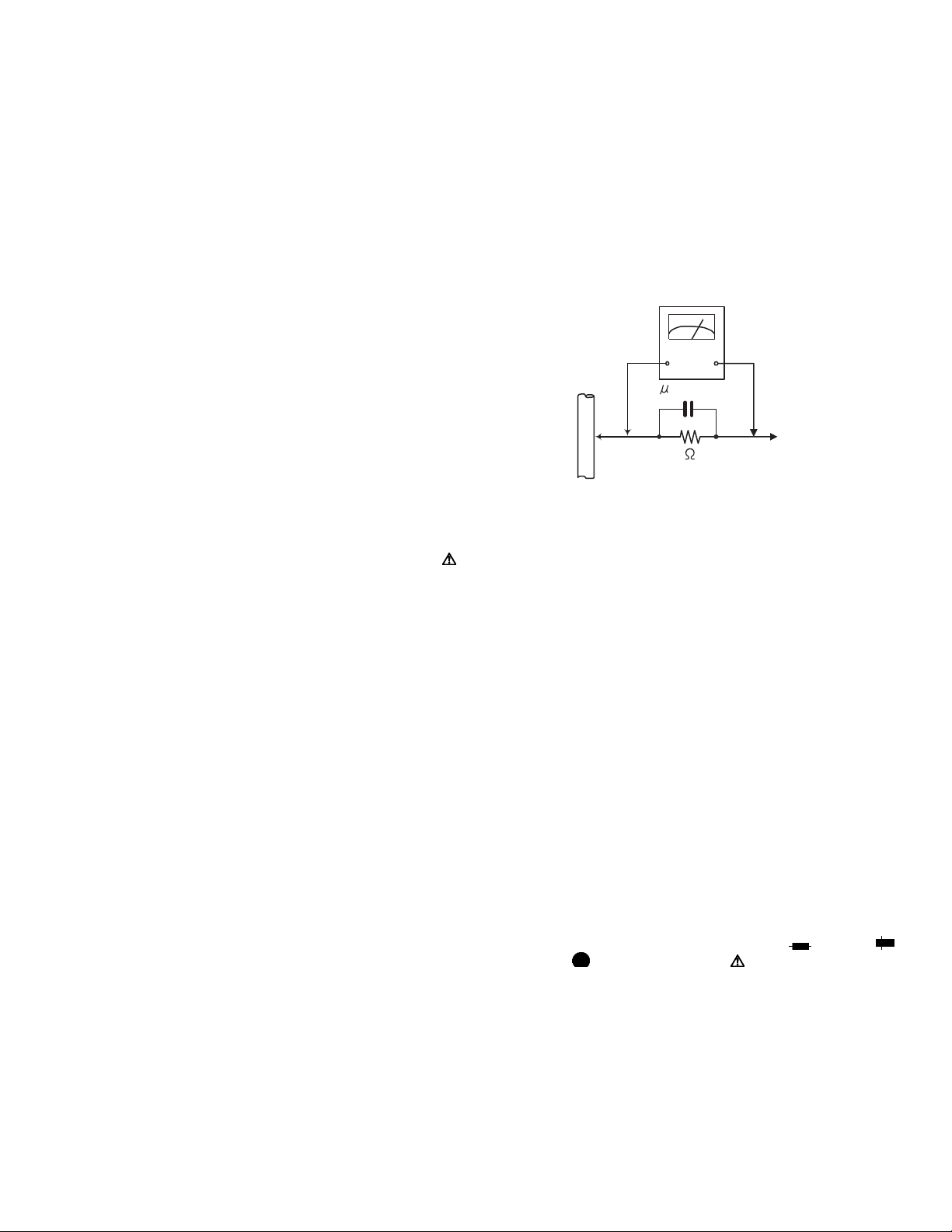
• Alternate check method
Plug the AC line cord directly into the AC outlet. Use an
AC voltmeter having, 1,000Ω per volt or more sensitivity
in the following manner. Connect a 1,500Ω 10W resistor
paralleled by a 0.15µF AC-type capacitor between an ex-
posed metal part and a known good earth ground.
Measure the AC voltage across the resistor with the AC
voltmeter.
Move the resistor connection to each exposed metal
part, particularly any exposed metal part having a return
path to the chassis, and measure the AC voltage across
the resistor. Now, reverse the plug in the AC outlet and
repeat each measurement. Voltage measured any must
not exceed 0.75 V AC (r.m.s.). This corresponds to 0.5
mA AC (r.m.s.).
AC VOLTMETER
(Having 1000
ohms/volts,
or more sensitivity)
0.15 F AC TYPE
Place this
probe on
1500 10W
Good earth ground
1.2 Warning
(1) This equipment has been designed and manufactured to
meet international safety standards.
(2) It is the legal responsibility of the repairer to ensure that
these safety standards are maintained.
(3) Repairs must be made in accordance with the relevant
safety standards.
(4) It is essential that safety critical components are replaced
by approved parts.
(5) If mains voltage selector is provided, check setting for local
voltage.
1.3 Caution
Burrs formed during molding may be left over on some parts
of the chassis.
Therefore, pay attention to such burrs in the case of preforming repair of this system.
1.4 Critical parts for safety
In regard with component parts appearing on the silk-screen
printed side (parts side) of the PWB diagrams, the parts that are
printed over with black such as the resistor ( ), diode ( )
and ICP ( ) or identified by the " " mark nearby are critical
for safety. When replacing them, be sure to use the parts of the
same type and rating as specified by the manufacturer.
(This regulation dose not Except the J and C version)
each exposed
metal part.
(No.MB320)1-3
Page 4
1.5 Preventing static electricity
Electrostatic discharge (ESD), which occurs when static electricity stored in the body, fabric, etc. is discharged, can destroy the laser
diode in the traverse unit (optical pickup). Take care to prevent this when performing repairs.
1.5.1 Grounding to prevent damage by static electricity
Static electricity in the work area can destroy the optical pickup (laser diode) in devices such as laser products.
Be careful to use proper grounding in the area where repairs are being performed.
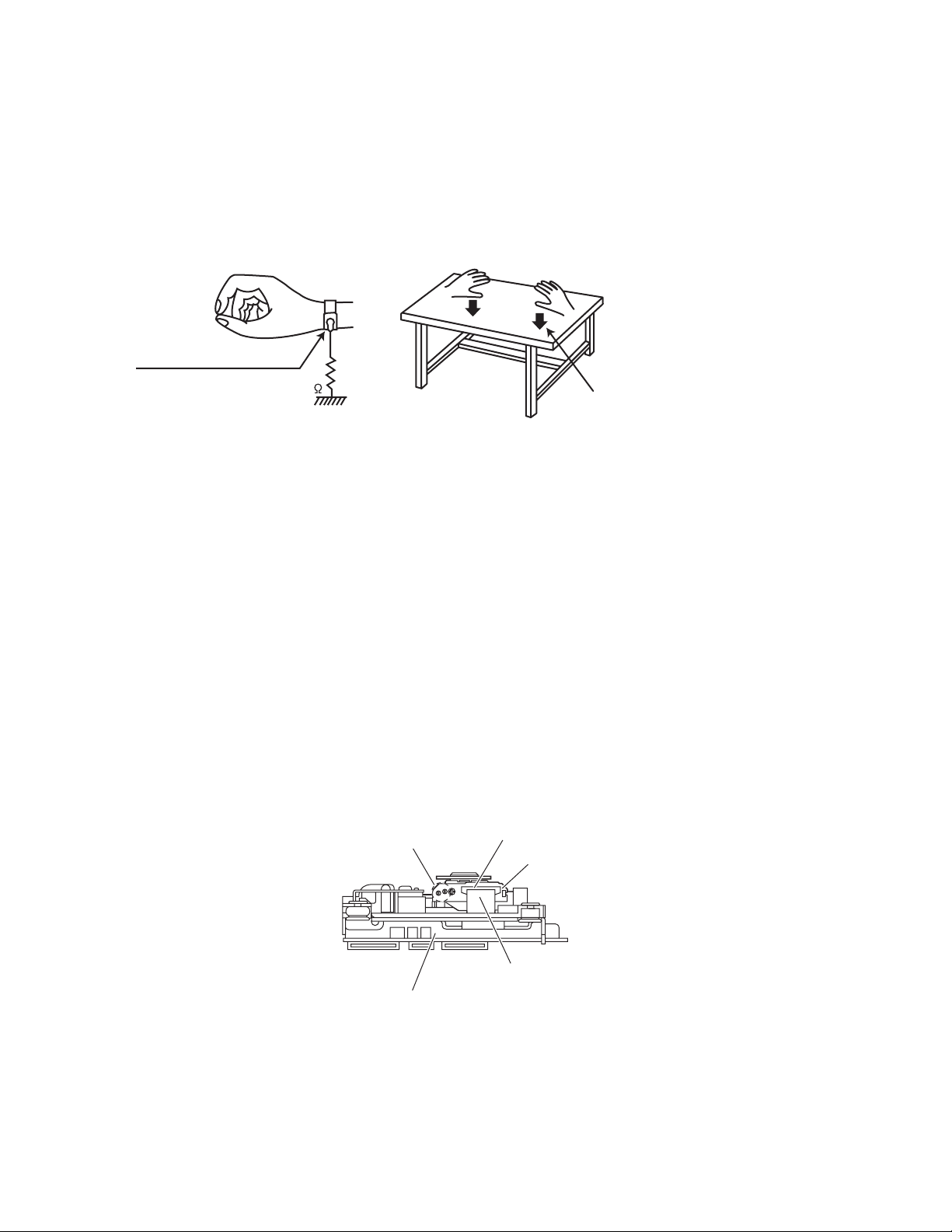
(1) Ground the workbench
Ground the workbench by laying conductive material (such as a conductive sheet) or an iron plate over it before placing the
traverse unit (optical pickup) on it.
(2) Ground yourself
Use an anti-static wrist strap to release any static electricity built up in your body.
(caption)
Anti-static wrist strap
1M
Conductive material
(conductive sheet) or iron palate
(3) Handling the optical pickup
• In order to maintain quality during transport and before installation, both sides of the laser diode on the replacement optical
pickup are shorted. After replacement, return the shorted parts to their original condition.
(Refer to the text.)
• Do not use a tester to check the condition of the laser diode in the optical pickup. The tester's internal power source can easily
destroy the laser diode.
1.6 Handling the traverse unit (optical pickup)
(1) Do not subject the traverse unit (optical pickup) to strong shocks, as it is a sensitive, complex unit.
(2) Cut off the shorted part of the flexible cable using nippers, etc. after replacing the optical pickup. For specific details, refer to the
replacement procedure in the text. Remove the anti-static pin when replacing the traverse unit. Be careful not to take too long a
time when attaching it to the connector.
(3) Handle the flexible cable carefully as it may break when subjected to strong force.
(4) I t is not possible to adjust the semi-fixed resistor that adjusts the laser power. Do not turn it.
1.7 Attention when traverse unit is decomposed
*Please refer to "Disassembly method" in the text for the pickup unit.
• Apply solder to the short land sections before the flexible wire is disconnected from the connecto on the servo board. (If the flexible
wire is disconnected without applying solder, the pickup may be destroyed by static electricity.)
• In the assembly, be sure to remove solder from the short land sections after connecting the flexible wire.
Short land section
Connector
Pickup
1-4 (No.MB320)
Card wire
Traverse mechanism assembly
Page 5
1.8 Important for laser products
!
1.CLASS 1 LASER PRODUCT
2.DANGER : Invisible laser radiation when open and inter
lock failed or defeated. Avoid direct exposure to beam.
3.CAUTION : There are no serviceable parts inside the
Laser Unit. Do not disassemble the Laser Unit. Replace
the complete Laser Unit if it malfunctions.
4.CAUTION : The CD,MD and DVD player uses invisible
laser radiation and is equipped with safety switches which
prevent emission of radiation when the drawer is open and
the safety interlocks have failed or are defeated. It is
dangerous to defeat the safety switches.
5.CAUTION : If safety switches malfunction, the laser is able
to function.
6.CAUTION : Use of controls, adjustments or performance of
procedures other than those specified here in may result in
hazardous radiation exposure.
Please use enough caution not to
see the beam directly or touch it
in case of an adjustment or operation
check.
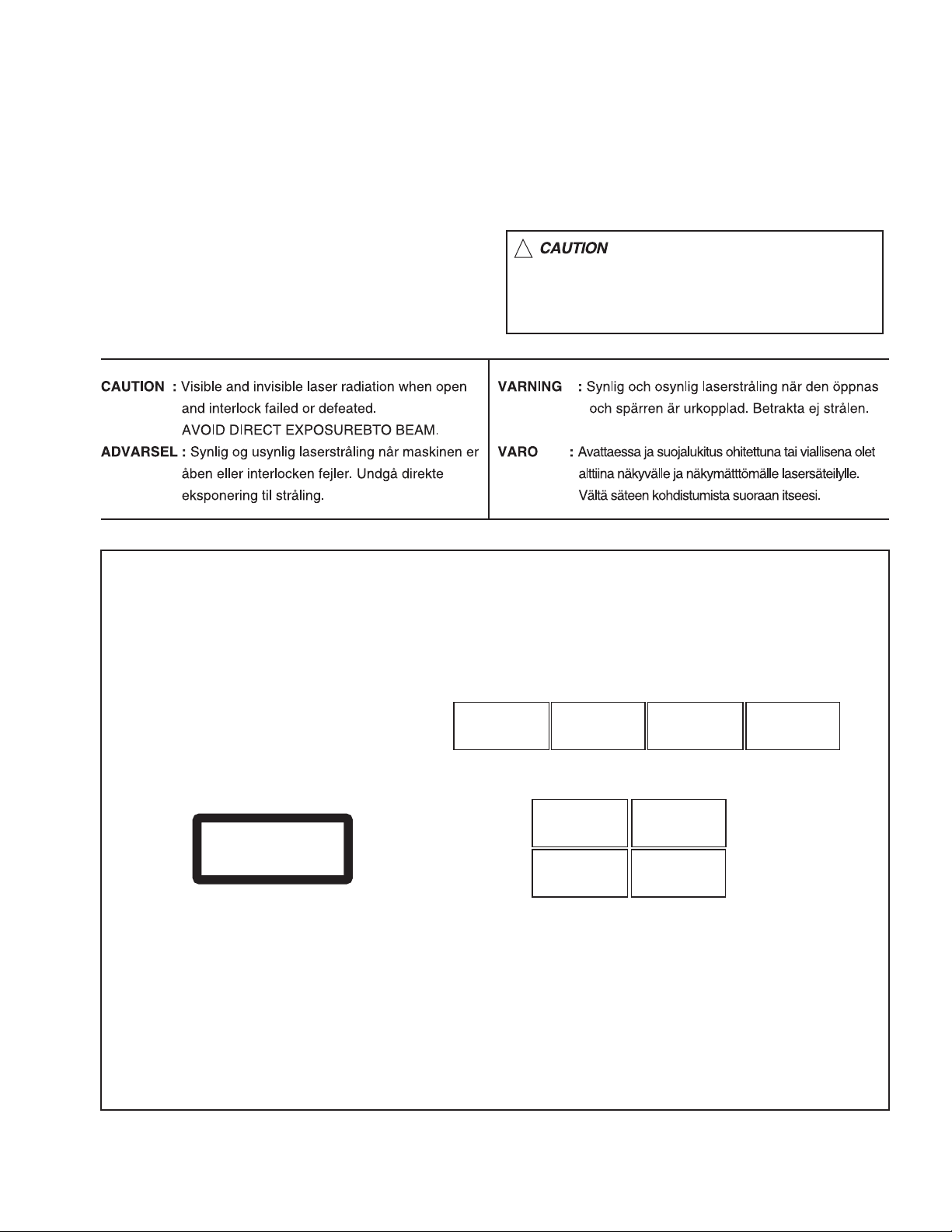
REPRODUCTION AND POSITION OF LABELS
WARNING LABEL
CAUTION : Visible and Invisible
laser radiation when open and
interlock failed or defeated.
AVOID DIRECT EXPOSURE TO
BEAM. (e)
CLASS 1
LASER PRODUCT
ADVARSEL : Synlig og usynlig
laserstråling når maskinen er
åben eller interlocken fejeler.
Undgå direkte eksponering til
stråling. (d)
CAUTION : Visible and Invisible
laser radiation when open and
interlock failed or defeated.
AVOID DIRECT EXPOSURE TO
BEAM. (e)
VARNING : Synlig och
osynling laserstrålning när
den öppnas och spärren är
urkopplad. Betrakta ej
strålen. (s)
VARNING : Synlig och
osynling laserstrålning när
den öppnas och spärren är
urkopplad. Betrakta ej
strålen. (s)
VARO : Avattaessa ja suojalukitus
ohitettuna tai viallisena olet alttiina
näkyvälle ja näkymättömälle
lasersäteilylle. Vältä säteen
kohdistumista suoraan itseesi. (f)
ADVARSEL : Synlig og usynlig
laserstråling når maskinen er
åben eller interlocken fejeler.
Undgå direkte eksponering til
stråling. (d)
VARO : Avattaessa ja suojalukitus
ohitettuna tai viallisena olet alttiina
näkyvälle ja näkymättömälle
lasersäteilylle. Vältä säteen
kohdistumista suoraan itseesi. (f)
(No.MB320)1-5
Page 6

SECTION 2
SPECIFIC SERVICE INSTRUCTIONS
This service manual does not describe SPECIFIC SERVICE INSTRUCTIONS.
1-6 (No.MB320)
Page 7

SECTION 3
DISASSEMBLY
3.1 Main body section
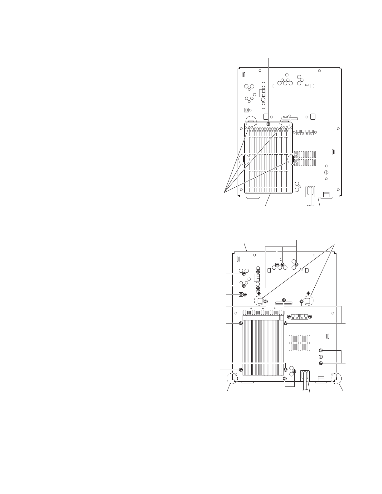
3.1.1 Removing the metal cover
(See Figs.1 to 3)
(1) From the both sides of the main body, remove the two
screws A attaching the metal cover. (See Figs.1 and 2.)
(2) From the back side of the main body, remove the six
screws B attaching the metal cover. (See Fig.3.)
(3) Remove the metal cover from the main body while lifting
the rear section of the metal cover in the direction of the arrow. (See Figs.1 and 2.)
Metal cover
Metal cover
A
Fig.1
Metal cover
B
A
Fig.2
B
B
Fig.3
(No.MB320)1-7
Page 8
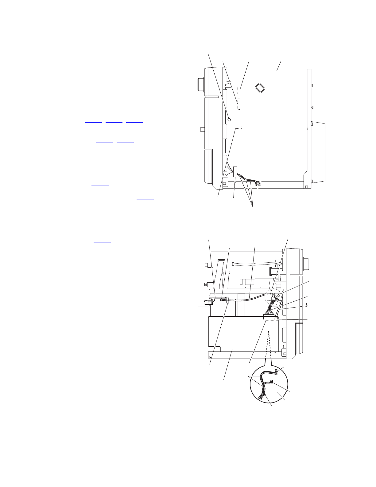
3.1.2 Removing the front panel assembly
(See Figs.4 to 7)
• Prior to performing the following procedures, remove the metal
cover.
(1) From the right side of the main body, remove the screw C
attaching the earth wires on the reverse side of the main
board. (See Fig.4.)
Reference:
After attaching the earth wires, fix them with a spacer as
before. (See Fig.4.)
(2) Remove the plastic rivet attaching the main board. (See
Fig.4.)
(3) From the inside of the main body, disconnect the card wires
from the connectors (CN303
ward side of the main board. (See Fig.4.)
(4) Remove the wire clamp fixing the wires and disconnect the
wires from the connector (CN301
side of the main body. (See Fig.5.)
Reference:
After connecting the wires to the connectors, fix the wires
with the wire clamp as before. (See Fig.5.)
(5) From the left side of the main body, disconnect the parallel
wire from the connector CN101
(See Fig.5.)
(6) Disconnect the wire from the connector CN119 on the
transformer board. (See Fig.5.)
Reference:
After connecting the wire, pass the wire through the slot
b of the holder board as before. (See Fig.5.)
(7) Remove the tie band fixing the wire and disconnect the
wire from the connector CN106
board. (See Fig.5.)
Reference:
• After connecting the wire, fix the wire with a new tie
band as before. (See Fig.5.)
• After connecting the wire, pass the wire through the
slot b of the holder board as before. (See Fig.5.)
(8) From the top side of the main body, remove the screw D
and screw D’ attach the front panel assembly to the main
body. (See Fig.6.)
Reference:
When attaching the screw D’, attach the earth wire with
it. (See Fig.6.)
(9) From the bottom side of the main body, remove the two
screws E and two screws F attaching the front panel assembly. (See Fig.7.)
(10) Release the claws a, remove the front panel assembly from
the main body in the direction of the arrow. (See Fig.7.)
, CN860, CN880) on the for-
, CN302) on the forward
on the transformer board.
on the speaker terminal
Plastic rivet
CN860
CN303
Speaker terminal board
CN106 Parallel wire
Tie band
Transformer board
CN880
Spacer
CN119
wires
Main board
C
Earth wires
Fig.4
Holder board
b
Wire
Parallel
wire
CN101
CN301
CN302
Main board
Wire clamp
1-8 (No.MB320)
Fig.5
Page 9
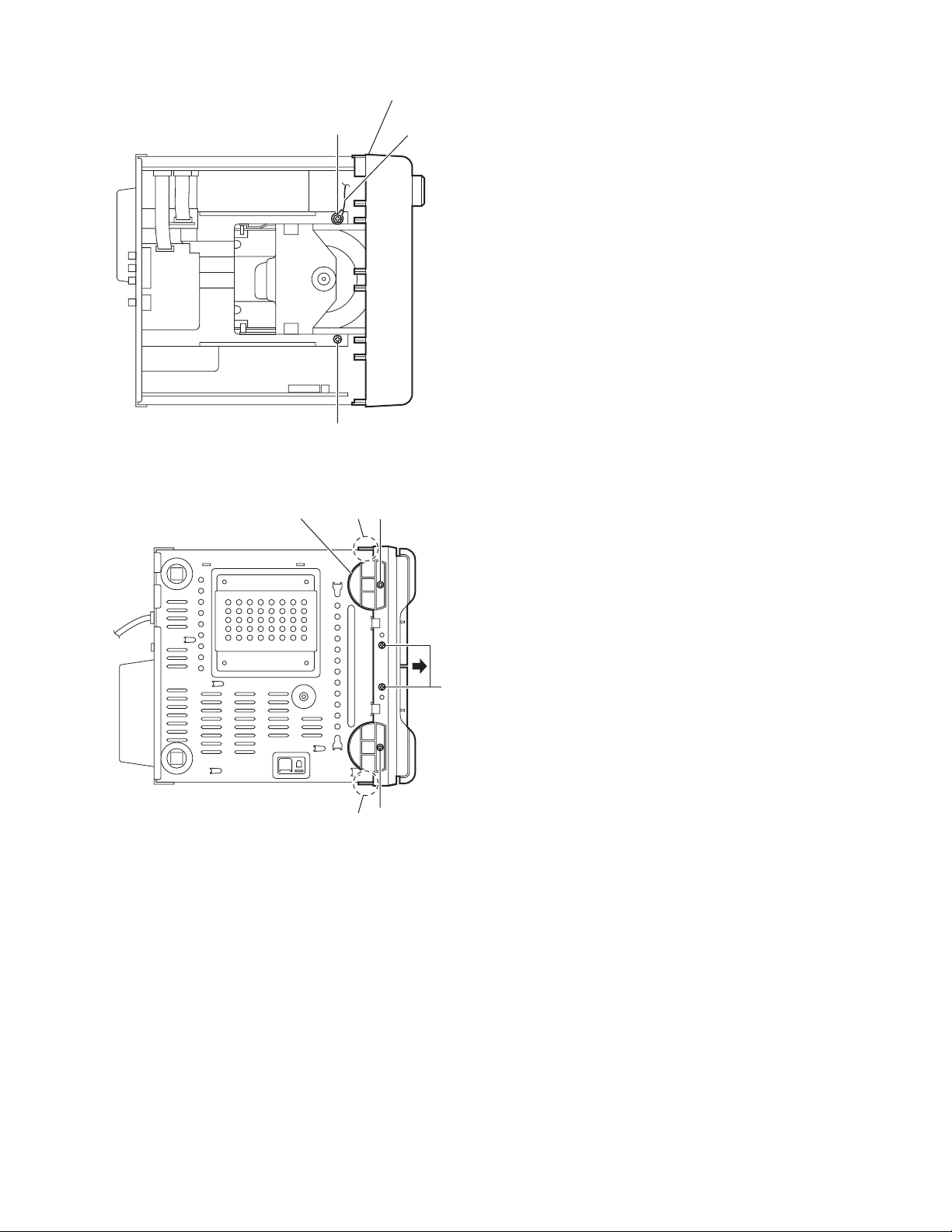
Front panel assembly
Fig.6
Front panel assembly
D'
D
a
Earth wire
E
Fig.7
F
a
E
(No.MB320)1-9
Page 10
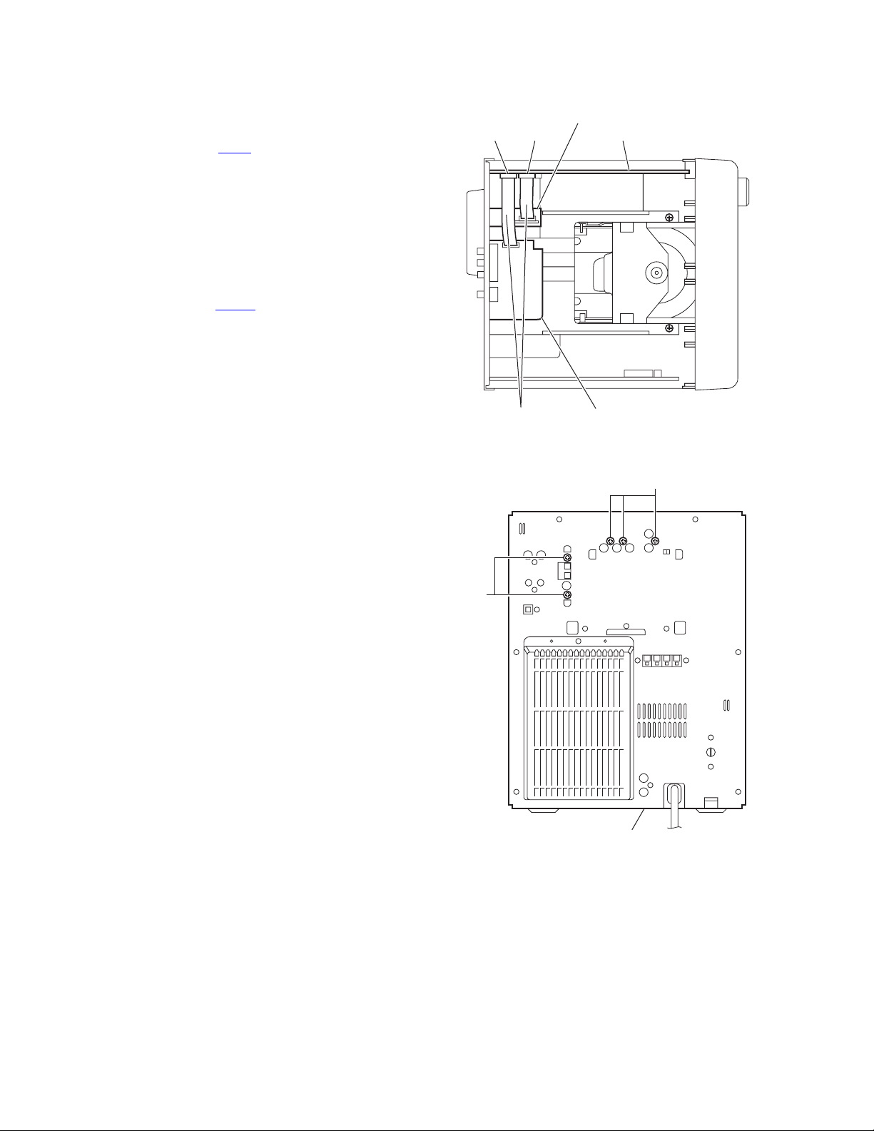
3.1.3 Removing the tuner
(See Figs.8 and 9.)
• Prior to performing the following procedures, remove the metal
cover.
(1) From the top side of the main body, disconnect the card
wire from the connector CN21
Fig.8.)
(2) From the back side of the main body, remove the two
screws G attaching the tuner to the rear panel. (See Fig.9.)
3.1.4 Removing the video board
(See Figs.8 and 9.)
• Prior to performing the following procedures, remove the metal
cover.
(1) From the top side of the main body, disconnect the card
wire from the connector CN410
Fig.8.)
(2) From the back side of the main body, remove the three
screws H attaching the video board to the rear panel. (See
Fig.9.)
on the main board. (See
on the main board. (See
Tuner
CN410 CN21 Main board
Video boardCard wires
Fig.8
H
G
Rear panel
Fig.9
1-10 (No.MB320)
Page 11
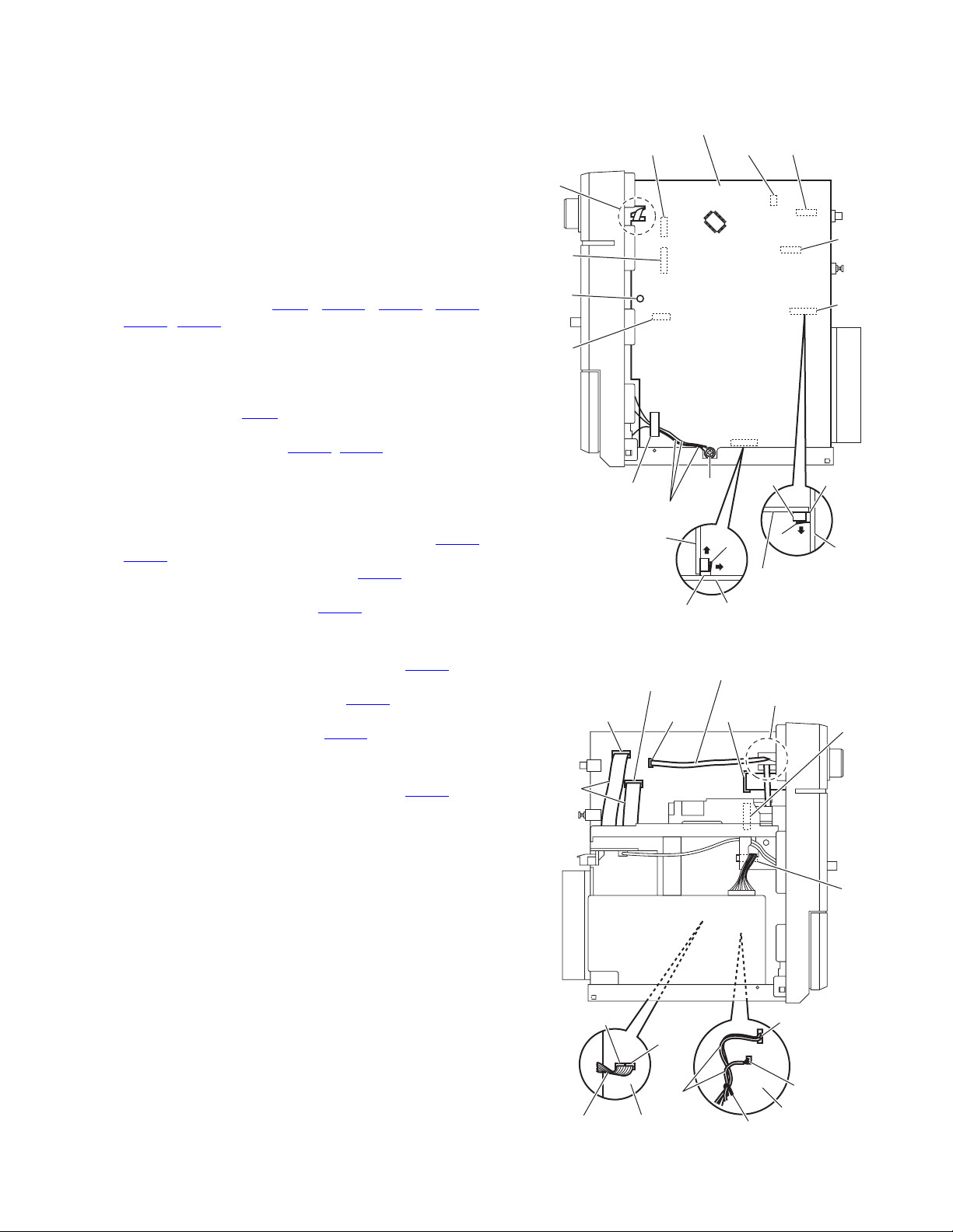
3.1.5 Removing the rear panel
(See Figs.8 to 11)
• Prior to performing the following procedures, remove the metal
cover.
(1) From the back side of the main body, remove the screw J
attaching the rear cover. (See Fig.10.)
(2) Release the sections c and remove the rear cover from the
rear panel. (See Fig.10.)
(3) Remove the two screws K and nineteen screws L attaching
the rear panel. (See Fig.11.)
Reference:
Remove the tuner and video board as required. (See
Figs.8 and 9.)
(4) From the both sides of the main body, release the sections
d of the center chassis in the direction of the arrow and release the joints e attaching the rear panel to the bottom
chassis. (See Fig. 11.)
J
c
Rear panelRear cover
Fig.10
Rear panel
L
L
e e
L
Bottom chassis
d
L
K
Fig.11
(No.MB320)1-11
Page 12
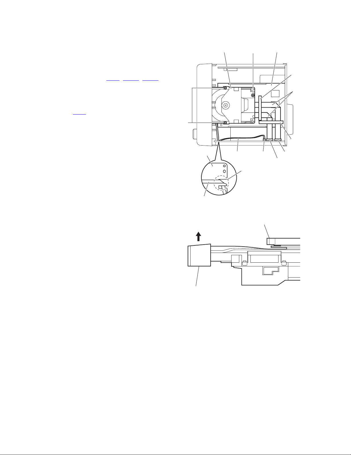
3.1.6 Removing the DVD mechanism assembly
r
r
(See Figs.12 and 13)
• Prior to performing the following procedures, remove the metal
cover, tuner and video board.
(1) From the top side of the main body, remove the three
screws M attaching the DVD mechanism assembly on the
center chassis. (See Fig.12.)
(2) From the forward side of the main board, disconnect the
card wires from the connectors (CN11
(See Fig.12.)
Reference:
When reassembly, pass the card wire through the section f of the main board before connecting the card wire
to the connector CN11
(3) Remove the spacers fixing the card wires. (See Fig.12.)
Reference:
After connecting the card wires, fix them with the spacers
as before. (See Fig.12.)
(4) From the inside of the main body, take out the DVD mech-
anism assembly.
(5) Remove the tray fitting from the DVD mechanism assembly
in the direction of the arrow. (See Fig.13.)
. (See Fig.12.)
, CN511, CN513).
DVD mechanism assembly
M
Main board
Card wire
Center chassis
M
Space
Card
wires
Space
CN513CN11
CN511
f
Card wire
Fig.12
DVD mechanism assembly
Tray fitting
Fig.13
1-12 (No.MB320)
Page 13
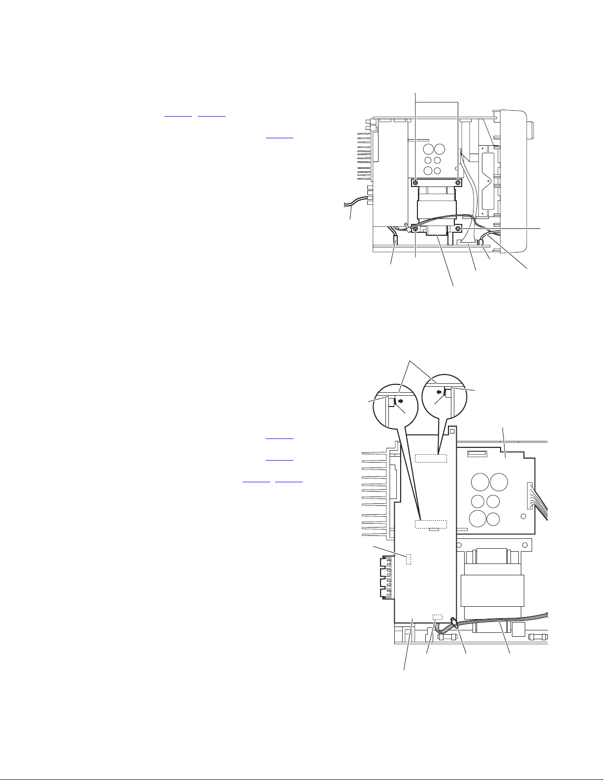
3.1.7 Removing the main board
(See Figs.14 and 15)
• Prior to performing the following procedures, remove the metal
cover, tuner, video board and rear panel.
(1) From the right side of the main body, remove the screw N
attaching the earth wires on the reverse side of the main
board. (See Fig.14.)
Reference:
After attaching the earth wires, fix them with a spacer as
before. (See Fig.14.)
(2) Remove the plastic rivet attaching the main board. (See
Fig.14.)
(3) From the inside of the main body, disconnect the card wires
from the connectors (CN11
CN860, CN880) on the forward side of the main board.
(See Figs.14 and 15.)
Reference:
When reassembly, pass the card wire through the section f of the main board before connecting the card wire
to the connector CN11
(4) Remove the wire clamp fixing the wires and disconnect the
wires from the connector (CN301
side of the main body. (See Fig.15.)
Reference:
After connecting the wires to the connectors, fix the wires
with the wire clamp as before. (See Fig.15.)
(5) Disconnect the parallel wire from the connectors (CN220
CN221) on the main board. (See Fig.15.)
(6) Release the lock g of the connector CN216 on the main
board in the direction of the arrow 1 and disconnect the
main board from the connector CN216
minal board toward this side. (See Fig.14.)
Note:
When releasing the lock g of the connector CN216
care not to break the lock. (See Fig.14.)
(7) Release the lock h of the connector CN201 on the primary
board in the direction of the arrow 2 and disconnect the
main board from the connector CN201
the arrow 3. (See Fig.14.)
Note:
When releasing the lock h of the connector CN201
care not to break the lock. (See Fig.14.)
, CN303, CN511, CN513,
. (See Fig.14.)
, CN302) on the forward
on the speaker ter-
, take
in the direction of
, take
Main board
CN880
f
CN860
Plastic
rivet
CN303
Spacer
Earth wires
,
Main board
CN201 Primary board
CN511
CN513 CN11 CN880
Card
wires
CN11 CN513
CN201
N
3
h
2
Fig.14
Card wire
CN511
CN216
CN206 CN216
g
Speaker terminal
board
f
Main
1
board
CN860
CN221
Main boardParallel wire
CN220
wires
CN303
CN301
CN302
Main board
Wire clamp
Fig.15
(No.MB320)1-13
Page 14
3.1.8 Removing the center chassis assembly
(See Fig.16)
• Prior to performing the following procedures, remove the metal
cover, tuner, video board and rear panel.
(1) From the top side of the main body, disconnect the card
wires from the connectors (CN11
main body.
Reference:
When reassembly, pass the card wire through the section f of the main board before connecting the card wire
to the connector CN11
(2) Disconnect the wire from the connector CN105 on the
speaker terminal board.
(3) Remove the two screws P attaching the center chassis as-
sembly.
(4) Take out the center chassis assembly from the main body.
.
, CN511, CN513) on the
CN511
CN513
CN11
Card wire
Main board
f
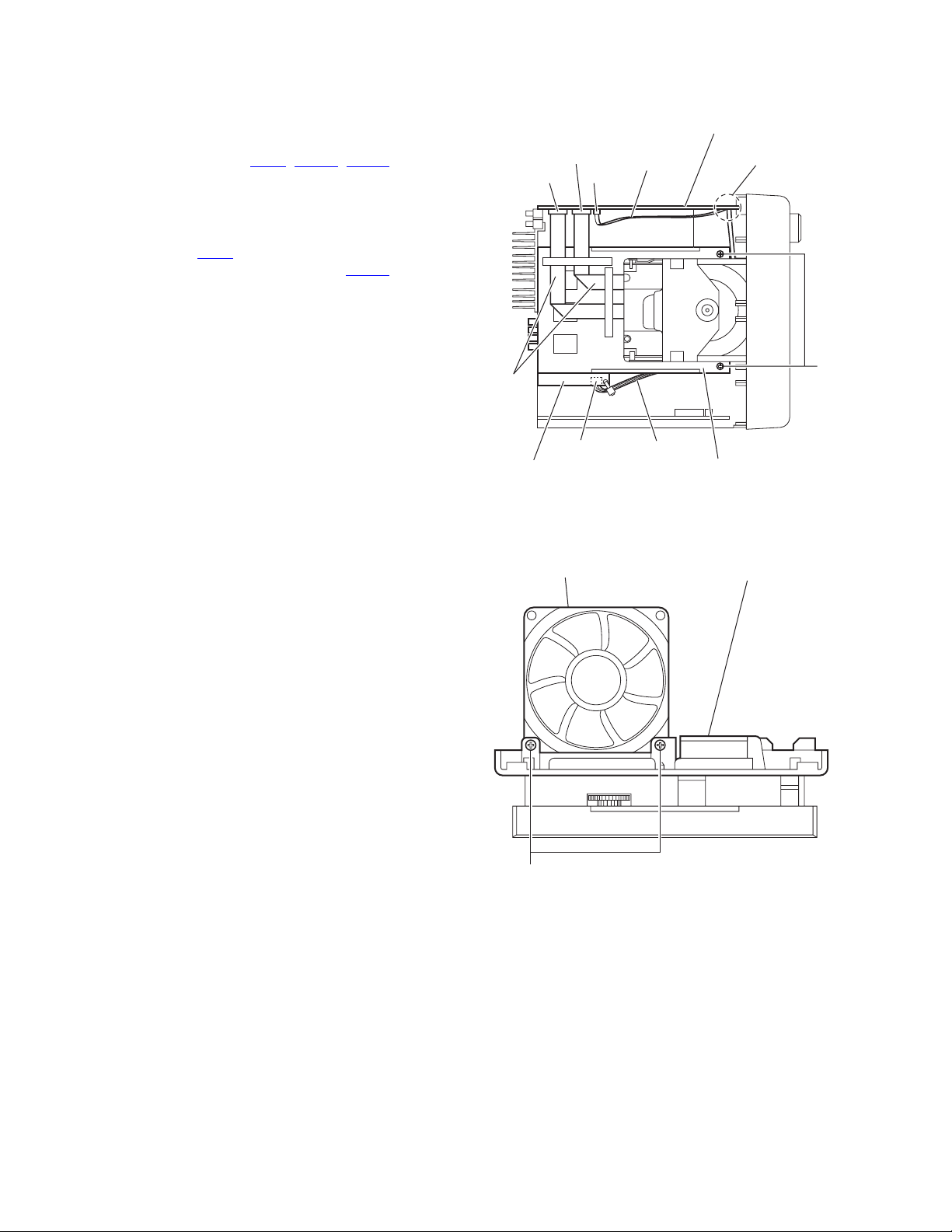
3.1.9 Removing the fan
(See Fig.17)
• Prior to performing the following procedure, remove the metal
cover, tuner, video board, rear panel and center chassis assembly.
From the bottom side of the center chassis assembly, remove
the two screws Q attaching the fan.
Card
wires
CN105
Speaker terminal board
Fan
P
Wire
Center chassis assembly
Fig.16
Center chassis assembly
1-14 (No.MB320)
Q
Fig.17
Page 15
3.1.10 Removing the transformer board
(See Fig.18)
• Prior to performing the following procedure, remove the metal
cover, tuner, video board, rear panel and center chassis assembly.
(1) From the top side of the main body, disconnect the wires
from the connectors (CN119
board.
(2) Disconnect the parallel wire from the connector CN101
the transformer board.
(3) Remove the four screws R attaching the transformer board
and take out the transformer board from the bottom chassis.
, CN250) on the transformer
on
R
3.1.11 Removing the speaker terminal board
(See Fig.19.)
• Prior to performing the following procedure, remove the metal
cover, tuner, video board, rear panel, main board and center
chassis assembly.
(1) From the top side of the main body, remove the tie band fix-
ing the parallel wire.
Reference:
After connecting the parallel wire, fix it with the new tie
band.
(2) Disconnect the parallel wire from the connector CN106
the speaker terminal board.
(3) Disconnect the parallel wire from the connector CN219
the primary board.
(4) Release the locks (i, j) of the connectors (CN205
and disconnect the speaker terminal board in an upward direction.
on
on
, CN214)
Power
cord
CN250
Speaker terminal board
CN205
R
Transformer board
Fig.18
i
j
CN101
CN119
CN214
Primary board
R
Wire
CN219
CN106
Speaker terminal board
Tie band
Fig.19
Parallel wire
(No.MB320)1-15
Page 16

3.1.12 Removing the regulator & surround amplifier board and main & subwoofer amplifier board
(See Figs.20 and 21)
• Prior to performing the following procedure, remove the metal
cover, tuner, video board, rear panel, main board, center chassis assembly and speaker terminal board.
(1) From the top side of the main body, disconnect the regula-
tor & surround amplifier and main & subwoofer amplifier
boards in an upward direction while releasing the locks (k,
m) of the connectors (CN202
board. (See Fig.20.)
(2) Take out the regulator & surround amplifier and main &
subwoofer amplifier boards at the same time from the main
body.
(3) Remove the two screws S attaching the leaf spring to the
heat sink and remove the regulator & surround amplifier
board from the heat sink. (See Fig.21.)
(4) Remove the three screws T attaching the main & subwoof-
er amplifier boards to the heat sink. (See Fig.21.)
, CN203) on the primary
Main & subwoofer
amplifier board
CN202
k
Primary board
m
Primary board
Regulator & surround amplifier board
Main & subwoofer amplifier board
Regulator & surround
amplifier board
CN203
Fig.20
1-16 (No.MB320)
S
Leaf spring
T
Heat sink
Fig.21
Page 17

3.1.13 Removing the primary board
r
(See Fig.22)
• Prior to performing the following procedure, remove the metal
cover, tuner, video board, rear panel, main board, center chassis assembly, speaker terminal board and regulator & surround amplifier board and main & subwoofer amplifier board.
(1) From the top side of the main body, disconnect the wire
from the connector CN119
Reference:
Pass the wire through the slot n of the holder board before connecting the wire to the connector.
(2) Remove the screw U attaching the primary board on the
bottom chassis.
(3) Remove the section p of the primary board and take out the
primary board from the main body.
on the transformer board.
Primary board Bottom chassis
p
U
Holde
board
n
Transformer board
Fig.22
CN119 Wire
(No.MB320)1-17
Page 18

3.1.14 Removing the FL board
(See Figs.23 and 24)
• Prior to performing the following procedures, remove the metal
cover and front panel assembly.
(1) From the front side of the front panel assembly, pull the vol-
ume knob out of the front panel assembly. (See Fig.23.)
(2) From the inside of the front panel assembly, remove the six
screws V attaching the FL board. (See Fig.24.)
(3) Release the claws q in the direction of the arrow and take
out the FL board from the front panel assembly. (See
Fig.24.)
Front panel assembly
Volume knob
Microphone knob
V
W
Fig.23
VV
q
FL board
V
W
Stay bracketFront panel assembly
Fig.24
1-18 (No.MB320)
Page 19

3.1.15 Removing the switch board
(See Figs.23 to 25)
• Prior to performing the following procedures, remove the metal
cover and front panel assembly.
(1) From the front side of the front panel assembly, pull the mi-
crophone knob out of the front panel assembly. (See
Fig.23.)
(2) From the inside of the front panel assembly, remove the six
screws W attaching the stay bracket. (See Fig.24.)
(3) From the inside of the front panel assembly, remove the
thirteen screws X attaching the switch board. (See Fig.25.)
(4) Take out the switch board from the front panel assembly.
3.1.16 Removing the cassette mechanism assembly
(See Fig.25)
• Prior to performing the following procedures, remove the metal
cover and front panel assembly.
(1) From the inside of the front panel assembly, remove the
three screws Y, screw Y’ and two screws Z attaching the
cassette mechanism assembly.
(2) Take out the cassette mechanism assembly from the front
panel assembly.
Reference:
• When attaching the screw Y’, attach the earth wire with it.
• When attaching the screws Z, attach the swing cam (L)/(R)
with them.
X
Z
Earth
wire
Swing cam (R)
assembly
Switch board
Y'
Cassette mechanism
assembly
Front panel assembly
X
Z
Y
Swing cam (L)
assembly
Fig.25
(No.MB320)1-19
Page 20

3.2 DVD mechanism section
• Prior to performing the following procedures, remove the DVD mechanism assembly from the main body.
(See "3.1.6 Removing the DVD mechanism assembly".)
3.2.1 Removing the tray assembly
(See Figs.1 to 3)
(1) From the right side of the DVD mechanism assembly, push
the slide cam and pull the tray assembly out of the DVD
mechanism assembly in the direction of the arrow. (See
Fig.1.)
(2) From the top side of the DVD mechanism assembly, re-
move the two screws A attaching the leaf spring to the
bushing and remove the leaf spring. (See Fig.2.)
(3) Remove the bushing of the tray assembly from the projec-
tion a on the DVD mechanism assembly and move the tray
assembly in the direction of the arrow. (See Fig.3.)
(4) Remove the claw b of the tray assembly from the DVD
mechanism assembly and take out the tray assembly. (See
Fig.3.)
Tray assembly
Slide cam
Leaf spring
DVD mechanism assembly
Fig.1
Bushing
A
DVD mechanism assembly
Fig.2
Projection a
Claw b
DVD mechanism assembly
Fig.3
Bushing
Tray assembly
1-20 (No.MB320)
Page 21

3.2.2 Removing the traverse mechanism assembly
(See Figs.4)
(1) From the bottom side of the DVD mechanism assembly, re-
move the three screws B and screw B’ attaching the
traverse mechanism assembly and take out the DVD
traverse mechanism assembly with the DVD servo board.
Reference:
When attaching the screw B’, attach the washer with it.
B'
Washer
DVD mechanism assembly
B'
3.2.3 Removing the DVD servo board
(See Figs.5 and 6)
• Prior to performing the following procedures, remove the
traverse mechanism assembly.
(1) From the side of the traverse mechanism assembly, solder
the short land sections c on the pickup. (See Fig.5.)
(2) From the bottom side of the traverse mechanism assem-
bly, release the lock of the connector CN101
servo board in the direction of the arrow 1 and disconnect
the card wire. (See Fig.6.)
Caution:
• Solder the short land sections c on the pickup before
disconnecting the card wire from the connector CN101
on the DVD servo board. If the card wire is disconnected without attaching solder, the pickup may be destroyed by static electricity. (See Figs.5 and 6.)
• When attaching the DVD servo board, be sure to remove solders from the short land sections c after connecting the card wire to the connector CN101
DVD servo board. (See Figs.5 and 6.)
(3) Disconnect the card wire from the connector CN201
DVD servo board. (See Fig.6.)
(4) Remove the two screws C attaching the DVD servo board.
(See Fig.6.)
(5) Remove the DVD servo board from the engagement sec-
tion d in an upward and remove the engagement section f
in the direction 3 while removing the engagement section e
in the direction of the arrow 2. (See Fig.6.)
on the DVD
on the
on the
B
Traverse mechanism assembly
Fig.4
Short land section c
Traverse mechanism assembly
Fig.5
CN101
C
Card wire
d
1
2
Card wire
1
B
DVD servo board
Pickup
CN201
C
f
3
e
DVD servo board
Traverse mechanism assembly
Fig.6
(No.MB320)1-21
Page 22

3.2.4 Removing the pickup
(See Figs.5,7 to 9)
• Prior to performing the following procedures, remove the
traverse mechanism assembly.
(1) From the side of the traverse mechanism assembly, solder
the short land sections c on the pickup. (See Fig.5.)
(2) Release the lock of the connector on the pickup in the di-
rection of the arrow and disconnect the card wire. (See
Fig.7.)
Caution:
• Solder the short land sections c on the pickup before
disconnecting the card wire from the connector on the
pickup. If the card wire is disconnected without attaching solder, the pickup may be destroyed by static electricity. (See Figs.5 and 7.)
• When attaching the pickup, be sure to remove solders
from the short land sections c after connecting the
card wire to the connector on the pickup. (See Figs.5
and 7.)
(3) Remove the screw D attaching the plate and thrust spring.
(See Fig.7.)
(4) Remove the engagement section g attaching the plate to
the feed holder and remove the plate with the thrust spring.
(See Fig.7.)
(5) Remove the shaft of the pickup from the section h on the
traverse mechanism assembly and remove the shaft from
the section i while moving it in the direction of the arrow.
(See Fig.8.)
(6) Remove the pickup from the section j of the traverse mech-
anism assembly and take out the pickup with the shaft.
(See fig.8.)
(7) From the bottom side of the pickup, remove the two screws
E attaching the SW actuator and LEAD spring. (See Fig.9.)
(8) Pull the shaft out of the pickup. (See Fig.9.)
Plate
D
Card wire
Feed holder
h
Shaft
Thrust spring
g
Connector
Fig.7
Traverse mechanism assembly
Pickup
i
Pickup
Shaft
j
Fig.8
Pickup
SW actuator
LEAD spring
E
Fig.9
1-22 (No.MB320)
Page 23

3.2.5 Attaching the pickup
(See Figs.5,7 to 10)
• See "3.2.4 Removing the pickup".
(1) Attach the shaft, SW actuator and LEAD spring to the pick-
up. (See Fig.9.)
(2) Align the pickup to the section j of the traverse mechanism
assembly first, and set the both ends of the shaft of the
pickup in the sections g and i of the traverse mechanism
assembly. (See Fig.8.)
(3) Attach the plate and thrust spring. (See Fig.7.)
(4) Remove solders from the short land sections c after con-
necting the card wire to the connector on the pickup. (See
Figs.5 and 7.)
(5) Turn the feed gear M in the direction of the arrow 1 to move
the pickup in the direction of the arrow 2. (See Fig.10.)
3.2.6 Removing the feed motor
(See Figs.7,11 and 12)
• Prior to performing the following procedures, remove the
traverse mechanism assembly.
(1) From the top side of the traverse mechanism assembly, re-
move the screw D attaching the plate and thrust spring.
(See Fig.7.)
(2) Remove the engagement section g attaching the plate to
the feed holder and remove the plate with the thrust spring.
(See Fig.7.)
(3) Remove the wires from the soldered section k on the spin-
dle motor board. (See Fig.11.)
Reference:
When attaching the feed motor, pass the wire through
the section m on the spindle base. (See Fig.11.)
(4) Remove the feed holder, feed motor, lead screw, feed gear
E and feed gear M at the same time after removing the two
screws F attaching the feed holder. (See Fig.11.)
(5) From the side of the feed holder, remove the two screws G
attaching the feed motor. (See Fig.12.)
Feed gear M
1
Feed gear M
Feed gear E
F
F
Feed holder
2
Fig.10
Feed motor
Spindle base
Spindle motor board
Fig.11
Pickup
Lead screw
Wires
Feed holder
m
k
G
Fig.12
(No.MB320)1-23
Page 24

3.2.7 Removing the spindle motor board
(See Figs.11 and 13)
• Prior to performing the following procedures, remove the
traverse mechanism assembly and DVD servo board.
(1) From the top side of the traverse mechanism assembly, re-
move the wires from the soldered section k on the spindle
motor board. (See Fig.11.)
(2) From the bottom side of the traverse mechanism assem-
bly, remove the three screws H attaching the spindle motor
board. (See Fig.13.)
3.2.8 Removing the switch board
(See Fig.14.)
(1) From the bottom side of the DVD mechanism assembly, re-
move the wires from the soldered section n on the switch
board.
(2) Lift the switch board while pressing the claw p of the DVD
mechanism assembly in the direction of the arrow and remove it from the section q.
Reference:
• Put the wires on the section r after attaching the switch
board to the DVD mechanism assembly.
• Fix the claw p on the DVD mechanism assembly with bonds
after attaching the switch board.
3.2.9 Removing the motor
(See Figs.14 and 15)
• Prior to performing the following procedures, remove the tray
assembly.
(1) From the bottom side of the DVD mechanism assembly, re-
move the wires from the soldered section n on the switch
board. (See Fig.14.)
(2) From the top side of the DVD mechanism assembly, re-
move the belt from the motor pulley. (See Fig.15.)
Note:
Take care not to attach grease on the belt.
(3) Remove the two screws J attaching the motor to the DVD
mechanism assembly and take out the motor from the bottom side of the DVD mechanism assembly. (See Fig.15.)
Reference:
Put the wires on the section r after attaching the motor to
the DVD mechanism assembly. (See Fig.14.)
H
Switch board
Soldered
section n
q
r
DVD mechanism assembly
J
Traverse mechanism assembly
Fig.13
Wires
Claw p
DVD mechanism assembly
Fig.14
Belt
1-24 (No.MB320)
Motor pulley
Fig.15
Page 25

3.3 Cassette mechanism assembly section
• Prior to performing the following procedures, remove the cassette mechanism assembly.
(See "3.1.16 Removing the cassette mechanism assembly".)
3.3.1 Removing the main motor and replacing the main belts
(See Figs.1 and 2)
(1) From the front side of the cassette mechanism assembly,
remove the two screws A attaching the main motor. (See
Fig.1.)
(2) From the back side of the cassette mechanism assembly,
remove the wires from the soldered sections a on the
switch board. (See Fig.2.)
Caution:
After reassembling, check the direction of the main motor and polarity of the wires. (See Fig.2.)
(3) Remove the main motor and main belts. (See Fig.2.)
Note:
When attaching the main belts, take care not to attach
grease on the main belts.
Cassette mechanism assembly
A
Fig.1
3.3.2 Replacing the F/R belts
(See Fig.3)
• Prior to performing the following procedures, remove the main
motor and main belts.
• Remove the wires of the main motor as required.
From the back side of the cassette mechanism assembly, remove the F/R belts from the flywheel 1 and flywheel 2.
Wire (Black)
Switch board
Main belt
Switch board
Cassette mechanism assembly
a
Wire (Red)
Cassette mechanism assembly
Main motor
Fig.2
Main belt
Flywheel 1
F/R belts
Fig.3
Flywheel 2
(No.MB320)1-25
Page 26

3.3.3 Removing the clutch assemblies
r
(See Figs.4 to 7)
• Prior to performing the following procedures, remove the main
motor, main belts and F/R belts.
• Remove the wires of the main motor as required.
(1) From the front side of the cassette mechanism assembly,
remove the three slit washers attaching the flywheel 1, flywheel 2 and flywheel 3. (See Fig.4.)
(2) From the back side of the cassette mechanism assembly,
pull out the flywheel 1, flywheel 2 and flywheel 3. (See
Fig.5.)
(3) Remove the stoppers in an upward direction. (See Fig.5.)
(4) Remove the springs from the sections b. (See Fig.6.)
(5) Release the claws c in the direction of the arrow, remove
the plates and pulleys. (See Fig.6.)
(6) Release the claws d in the direction of the arrow, remove
the guide arms. (See Fig.7.)
Note:
When attaching the guide arms, attach the springs with
them as before. (See Fig.7.)
(7) Remove the cam gears in an upward direction. (See Fig.7.)
(8) Take out the clutch assemblies from the cassette mecha-
nism assembly. (See Fig.7.)
Cassette mechanism assembly
Slit washer
Slit washer
Fig.4
Cassette mechanism assembly
Slit washer
Flywheel 1
Spring
b
d
Stopper
Flywheel 3
Fig.5
Cassette mechanism assembly
Pulley
c
Plates
Fig.6
Cassette mechanism assembly
d
Clutch assemblyClutch assembly
Flywheel 2
Spring
b
Stoppe
Pulley
c
1-26 (No.MB320)
Spring
Guide arm
Spring
Guide arm
Fig.7
Cam gearCam gear
Page 27

3.3.4 Removing the leaf switches
(See Fig.8)
(1) From the back side of the cassette mechanism assembly,
remove the solders from the soldered sections e attaching
the leaf switches on the switch board.
(2) From the front side of the cassette mechanism assembly,
pull out the leaf switches.
3.3.5 Removing the switch board
(See Fig.8)
(1) From the back side of the cassette mechanism assembly,
remove the solders from the soldered sections (f, g) connecting the wires.
Note:
After reassembling, check the polarity of the wires.
(2) Release the claws h in the direction of the arrow and re-
move the switch board from the cassette mechanism assembly.
Wire (Black)
e
h
h
Switch board
h
f
Wire (Red)
Switch board
e
e
h
h
3.3.6 Removing the PB head block
(See Fig.9)
(1) From the bottom side of the cassette mechanism assem-
bly, remove the tie band fixing the wire.
Reference:
After reassembling, fix the wire with a new tie band as
before.
(2) From the front side of the cassette mechanism assembly,
release the claw i in the direction of the arrow 1 and pull out
the pinch roller in an upward direction.
(3) Remove the screw B attaching the PB head.
(4) Remove the spring from the section j.
(5) Move the PB head block in the direction of the arrow 2 and
remove the hooks k from the PB head block.
(6) Take out the PB head block from the cassette mechanism
assembly.
g
Spring
j
k
Cassette mechanism assembly
Fig.8
Cassette mechanism assembly
k
2
g
PB head
k
i
1
PB head block
B
Fig.9
Pinch roller
Wire
Tie band
(No.MB320)1-27
Page 28

3.3.7 Removing the R/P head block
(See Fig.10)
(1) From the front side of the cassette mechanism assembly,
release the claw m in the direction of the arrow 1 and pull
out the pinch roller L in an upward direction.
(2) Release the claw n in the direction of the arrow 2 and pull
out the pinch roller R in an upward direction.
(3) From the bottom side of the cassette mechanism assem-
bly, remove the screw C attaching the R/P head board.
(4) From the front side of the cassette mechanism assembly,
remove the two screws D attaching the R/P head.
(5) Take out the R/P head block (R/P head and R/P head
board) from the cassette mechanism assembly.
Cassette mechanism assembly
m
R/P head
n
21
Pinch roller L
R/P head
board
C
D
Pinch roller R
D
Fig.10
1-28 (No.MB320)
Page 29

3.4 Speaker section
3.4.1 Removing the net assembly
(See Fig.1)
(1) From the front side of the speaker main body, remove the
sections a of the net assembly toward this side.
Net assembly
aa
a
a
aa
Fig.1
(No.MB320)1-29
Page 30

3.4.2 Removing the front panel assembly
(See Figs.2 and 3)
• Remove the net assembly as required.
(1) Insert the tip of a flat-bladed screwdriver or similar tool into
the space between the speaker main body and front panel
assembly, and lift the front panel assembly little by little to
remove the sections b. (See Fig.2.)
Note:
To prevent damaging the front panel assembly and
speaker main body, insert cushioning plates etc. into the
space between the speaker main body and front panel
assembly. (See Fig.2.)
(2) From the inside of the front panel assembly, disconnect the
yellow and black wires from the terminal of the tweeter.
(See Fig.3.)
3.4.3 Removing the tweeter
(See Fig.3)
• Prior to performing the following procedures, remove the front
panel assembly.
(1) Disconnect the blue and white wires from the terminal of
the tweeter.
(2) Remove the two screws A attaching the tweeter.
(3) Take out the tweeter from the front panel assembly.
Front panel assembly
b
Wire(white)
Wire(black)
Cushioning
plate, etc.
Fig.2
A
Flat-bladed
screwdriver,etc.
Tweeter
Wire(blue) Terminal
Wire(yellow)
Front panel assembly
A
Fig.3
1-30 (No.MB320)
Page 31

3.4.4 Removing the speaker
(See Figs.4 and 5)
• Prior to performing the following procedures, remove the front
panel assembly.
(1) From the front side of the speaker main body, remove the
four screws B attaching the speaker. (See Fig.4.)
(2) Take out the speaker from the speaker main body and dis-
connect the wires (red/black, yellow/black) from the terminal of the speaker. (See Fig.5.)
Speaker
BB
Fig.4
Speaker
Terminal
Wires (yellow/black) Wires (red/black)
Fig.5
(No.MB320)1-31
Page 32

SECTION 4
ADJUSTMENT
4.1 Measurement instruments required for adjustment
(1) Low frequency oscillator
This oscillator should have a capacity to output 0dBs to
600Ω at an oscillation frequency of 50Hz-20kHz.
(2) Attenuator impedance : 600Ω
(3) Electronic voltmeter
(4) Distortion meter
(5) Frequency counter
(6) Wow & flutter meter
(7) Test tape
VTT703 : Head azimuth
(8) Blank tape
TYPE l : AC-514
(9) Test disc : VT-501, CTS-1000
4.2 Measurement conditions
Power supply voltage : AC110V / AC127V / AC220V /
AC230V to AC240V 50Hz / 60Hz (Adjustable with the voltage selector)
Reference output : Speaker : 0.775V/4Ω
Headphone : 0.077V/32Ω
Reference frequency
and input level
Measurement output
terminal
Load resistance : 4Ω
4.3 Radio input signal
AM frequency : 400Hz
AM modulation : 30%
FM frequency : 400Hz
FM frequency deviation : 22.5kHz
: 1kHz, AUX : -8dBs
: at Speaker J200
4.4 Tuner section
FM Band cover : 87.5~108.0MHz
AM Band cover : 531~1,602kHz (at 9kHz)
530~1,600kHz (at 10kHz)
Voltage applied to tuner : +B : DC5.7V
VT : DC 12V
Reference measurement
output
Input positions : AM : Standard loop antenna
4.5 Standard measurement position of volume
Function switch : to Tape
Beat cut switch : to Cut
Super Bass/Active hyper Bass : to OFF
Bass Treble : to Center
Adjustment of main volume to reference output : VOL : 28
Precautions for measurement
(1) Apply 30pF and 33kΩ to the IF sweeper output side and
0.082µ F and 100kΩ in series to the sweeper input side.
(2) The IF sweeper output level should be made as low as
possible within the adjustable range.
(3) Since the IF sweeper is a fixed device, there is no need
to adjust this sweeper.
(4) Since a ceramic oscillator is used, there is no need to
perform any MIX adjustment.
(5) Since a fixed coil is used, there is no need to adjust the
FM tracking.
(6) The input and output earth systems are separated. In
case of simultaneously measuring the voltage in both of
the input and output systems with an electronic voltmeter
for two channels, therefore, the earth should be connected particularly carefully.
(7) In the case of BTL connection amp., the minus terminal
of speaker is not for earthing. Therefore, be sure not to
connect any other earth terminal to this terminal. This
system is of an BTL system.
(8) For connecting a dummy resistor when measuring the
output, use the wire with a greater code size.
(9) Whenever any mixed tape is used, use the band pass fil-
ter (DV-12).
: 26.1mV(0.28V)/3Ω
FM : TP1 (hot) and TP2 (GND)
1-32 (No.MB320)
Page 33

4.6 Arrangement of adjusting positions
4.6.1 Tape recorder section
Items
Cassette Head
Azimuth Alignments
Measurement
conditions
Test tape
:VT703 (10kHz)
Measurement output
terminal
:Left and Right
speaker output
(6-ohm loaded)
or
Headphone Output
(32-ohm loaded)
PB Head
(Deck-A)
Head azimuth screw
(Forward side)
Head azimuth screw
(Reverse side)
1. Playback the test tapeVT703 (10KHz) or equivalent.
2. Adjust the head azimuth screw to obtain maximum
output and both output of L / R is in 3dB.
3. Put on the screw lock paint after alignments.
Cassette mechanism assembly
(Front side)
Head azimuth screw
(Forward side)
Measurement method
REC/PB Head
(Deck-B)
Head azimuth screw
(Reverse side)
Maximum output
Standard
values
Adjusting
positions
Adjust the head
azimuth screw
only when the
head has been
changed.
Recording Bias
Frequency Alignment
Test tape
:TYPE I AC-514
Measurement output
terminal
:Erase head terminal
(CN308 8-Pin)
1. Insert the recording tape in deck-B.
80kHz+/-3kHz
2. Starting the recording.
3. Adjust the oscillation frequency to 80kHz+/-3kHz by
core of Oscillation coil of L301.
Use the HighImpedance Probe
or Frequency
counter input.
(No.MB320)1-33
Page 34

4.7 Service mode
4.7.1 Confirming contents
(1) System micon reset
(2) System micon cold start
(3) FL display check
(4) Micon version check
(5) DVD region check
(6) DVD test mode
4.7.2 Confirming methods
1. System micon reset
When DVD mechanism stuck, this may solve the problem without removing/inserting power cord.
Press the
STANDBY/ON, CANCEL
and PAUSE buttons on the main unit
simultaneously.
System micon is initialized.
2. System micon cold start
This function clears all user setting, and return to initial setting.
Daily timer, REC timer
Tuner preset
SEA preset
Last condition (Source, Volume)
Press the SET UP, "4" and "0" buttons
twice on the remote controller at standby.
FL indication
" COLD SET "
This unit returns to initial setting.
3. FL display check
This enables all FL segment light up.
1-34 (No.MB320)
Press the SET UP, "4" and "+10" buttons
on the remote controller at standby.
All of the FL displays light up.
Page 35

4. Micon version check
r
You can confirm Micon version and destination.
Insert the power cord in an outlet.
Press the SET UP, "4" and DIMMER
buttons on the remote controller.
System micon version is indicated on
the FL display.
Press the SET UP, "4" and DIMMER
buttons on the remote controller.
DVD backend firmware version is indicated
on the FL display.
Press the SET UP, "4" and DIMMER
buttons on the remote controller.
Model number is indicated
on the FL display.
Press the SET UP, "4" and DIMMER
buttons on the remote controller.
Destination is indicated on the FL display.
5. DVD region check
You can confirm DVD region number.
Press the
buttons on the main unit at standby.
STANDBY/ON
and DVD LEVEL
FL indication
REGION
DVD region number is indicated on the on screen display.
(Example) "2U ver.0097 MX-JD3 / FMU-DE2-1"
DVD unit numbe
Firmware model
Firmware version
DVD destination
(No.MB320)1-35
Page 36

6. DVD test mode
Insert the power cord in an outlet while
SET
pressing the
and buttons on the
main unit simultaneously.
Status: You can check DVD unit condition
DVD unit condition is indicated on the FL
display.
Initialize (Normal):
Initialize user setting
Press the PAUSE button on the main unit.
(Example) "TEST 2U 0"
Disc reading preset condition
0: DVD/CD learned
1: only CD learned
2: only DVD learned
3: DVD/CD not learned
DVD region number
DVD destination
FL indication
(Example) "TEST 2U 00"
Press the STANDBY/ON button on the
main unit or remote controller.
Disconnect the power cord in an outlet.
Insert the power cord in an outlet.
Press the STANDBY/ON button on the
main unit or remote controller.
Initialization is complete.
Initialize (Permanent):
Initialize "QUICK PLAY" setting
Press the button on the main unit for two seconds.
FL indication
(Example) "TEST 2U 33"
Press the STANDBY/ON button on the
main unit or remote controller.
Disconnect the power cord in an outlet.
Insert the power cord in an outlet.
Press the STANDBY/ON button on the
main unit or remote controller.
Insert a new VT-501 disc, play this disc.
Eject the VT-501 disc.
Insert a new CTS-1000 disc, play this disc.
Eject the CTS-1000 disc.
Press the STANDBY/ON button on the
main unit or remote controller.
1-36 (No.MB320)
Initialization is complete.
1
Page 37

1
Device key:
Program DEVICE KEY code
Press the button on the main unit.
Device key check:
Check device key checksum
Press the MENU button on the remote controller.
Micon version check:
Check micon version number
Press the MENU button on the remote controller.
FL display check:
Check all FL segments
Press the MENU button on the remote controller.
STANDBY/ON LED blink.
PC application run.
Automatically power off
Wait until PC application complete
FL indication
(Example) " "
Device key check is complete.
FL indication
(Example) " SSSS BBBB "
Micon version check is complete.
All of the FL displays light up.
FL display check is complete.
Reference:
If never programmed, "FFFF"
will appear.
S: System micon version
B: Backend firmware
Check mode
Press the MENU button on the remote controller.
FL indication
" CHECK "
START PLAY:
Start playing
Press the "1" button on the remote controller.
WOBBLE:
WOBBLE display
Press the "2" button on the remote controller.
CD laser:
CD laser current display
Press the "4" button on the remote controller.
DVD laser:
DVD laser current display
Press the "5" button on the remote controller.
2
FL indication
" CHECK "
FL indication
" "
FL indication
" "
FL indication
" "
(No.MB320)1-37
Page 38

2
DVD jitter:
DVD single-layer jitter display
Press the "6" button on the remote controller.
EEPROM (B):
EEPROM data display (Backward)
Press the "7" button on the remote controller.
EEPROM (F):
EEPROM data display (Forward)
Press the "8" button on the remote controller.
Temperature:
Pickup temperature display
Press the "9" button on the remote controller.
DVD jitter:
DVD jitter (D/L - S/L) display
Press the "10" button on the remote controller.
EEPROM ini.:
EEPROM initialize
Press the "+10" button on the remote controller.
Monitor:
Monitor change
Press the "0" button on the remote controller.
FL indication
" "
FL indication
" "
FL indication
" "
FL indication
" "
FL indication
" "
FL indication
" FFFF FFFF "
FL indication
" "
STOP:
Disc stop
Press the STOP button on the remote controller.
FL indication
" CHECK "
PLAY:
Laser & jitter display
Press the DVD/CD PLAY button on the remote controller.
Check mode is complete.
Press the STANDBY/ON button
on the main unit or remote controller.
FL indication
" "
1-38 (No.MB320)
Page 39

4.7.3 Indicating check for FL display
No. Function FL display Note
1 SOURCE
DVD (DVD-V)
DVD (DVD-A)
DVD (CD)
DVD (MP3)
DVD (WMA)
DVD (ASF)
DVD (VCD)
DVD (VCD)
DVD (SVCD)
DVD (SVCD)
DVD (JPEG)
TAPE A
TAPE B
AUX
AM
FM
2 TUNER
PRESET MEMOERY
PRESET MEMOERY
PRESET MEMOERY
1
2.
3
4
1:
1
2:
3
4
1
2.
3
4
1:
1
2:
3
4
C
D
1
2.
1:
1
2:
3
4
1
2.
1
2
2.
1
2:
3
1
2.
1
2
2.
1
2:
3
1
2.
1
2
2.
1
2:
3
V
D
1
2.
1:
1
2:
3
V
D
1
2.
S
V
1
2.
S
V
1
2.
1
2.
1
2
2.
T
A
T
A
A
U
X
A
M
F
M
TTU
N
E
U
N
E
S
E
P
S
T
O
1:
P
P
1
1
R
R
T
1R2
P
B
1
2:
3
P
B
J
P
E
E
E
I
N
6
0
2
0
8.
0
F
M
A
M
E
D
Exchange to mm:ss (60-99 minutes)
4
Display "--:--" (over 100 minutes)
4
4
without PBC
4
with PBC
C
without PBC
4
with PBC
C
G
: PRESET NUMBER
: PRESET NUMBER
0
BLINKING
BLINKING
3 TAPE
PLAY TAPE A
PLAY TAPE B
REVERSE TAPE B
FF/REW TAPE A
FF/REW TAPE B
REC
DISC REC
DISC REC STOP
DUBBING
4 VOLUME
UP/DOWN
MAX
MIN
BEATBOOSTER
ON
OFF
ACTIVEBASS
LEVEL CHANGE
LEVEL CHANGE
LEVEL CHANGE
T
A
P
E
T
A
P
E
T
A
P
E
E
V
E
R
S
E
T
A
P
E
T
A
P
E
T
A
P
E
DRI
S
C
R
E
C
"DISC REC FINISHED" SCROLL
D
U
B
B
I
N
G
V
O
L
U
M
E
3
0
V
O
L
U
M
E
M
A
X
V
O
L
U
M
E
M
I
N
R
H
Y
T
H
M
A
X
O
N
R
H
Y
T
H
M
A
X
O
F
F
A
C
T
I
V
E
B
A
A
C
T
I
V
E
B
A
A
C
T
I
V
E
B
A
0
S
S
1
S
S
2
S
S
(No.MB320)1-39
Page 40

No. FL display Note
Function
4 SOUND MODE
D
A
N
C
DANCE
HALL
STADIUM
ROCK
POP
CLASSIC
FLAT
USER1
USER2
USER3
OFF
H
S
T
A
R
P
C
L
A
F
U
S
U
S
U
S
O
E
A
L
L
D
I
U
M
O
C
K
O
P
S
S
I
C
L
A
T
E
R
1
E
R
2
E
R
3
F
F
3D PHONIC
3
D
A
C
T
I
O
3D ACTION
3D DRAMA
3D THEATER
3D PHONIC OFF
3
D
D
R
A
3
D
T
H
E
A
3
D
O
F
F
Note: DVD-A cannot be activated 3D-Phonic.
Also at Karaoke condition, 3D-PHONIC is prohibited.
Display should be done after STATUS reception.
N
M
A
T
E
R
TONE SETTING
S
E
A
C
O
N
TONE MEMORY
TONE MEMORY
TONE MEMORY
TONE MEMORY
TONE MEMORY
B
A
S
S
T
R
E
U
S
E
R
M
E
M
O
T
0
0
1
R
Y
RANGE: 0 +3
RANGE: -3 0 +3
NUMBER BLINKING
LEVEL ADJUST
BALANCE
SUBWOOFER
EFFECT
S.
L
/
R
W
O
O
F
E
R
E
F
F
E
C
T
RANGE: R-6 0 L-6
RANGE: 0/1/2/3/4
RANGE: 1 3
DVD LEVEL
D
V
D
L
E
V
E
L
LEVEL 1
LEVEL 2
LEVEL 3
D
V
D
L
E
V
D
V
D
L
E
V
1
E
L
2
E
L
3
KARAOKE
K
A
R
A
O
K
KARAOKE ON
KARAOKE OFF
O
F
E
F
MIC MIX
M
I
C
M
I
MIC MIX
MIC OFF
M
I
C
X
O
F
F
ECHO
ECHO
ECHO OFF
E
C
H
O
E
C
H
O
O
F
F
RANGE: 1 3
KEY CONTROL
KEYCON
K
E
Y
C
O
N
RANGE: -6 0 +6
1-40 (No.MB320)
Page 41

No. Note
FL displayFunction
5 SLEEP
SLEEP 10 120
S
L
E
E
P
RANGE: 10/20/30/60/120
DIMMER
DIMMER
NORMAL
D
I
M
M
E
R
N
O
R
M
A
L
CLOCK
ADJUST
SET
SET
A
M
A
M
C
1
2:
0
0
1
2.
0
0
L
O
C
K
O
K
HOUR BLINKING
MINUTE BLINKING
DAILY TIMER
SELECT
SET
SET
SET
SET
SET
SET
SET
SET
D
A
I
L
Y
T
I
M
E
R
O
N
O
N
O
F
O
F
T
T
V
O
A
M
1
2:
0
0
HOUR BLINKING
A
M
1
2:
0
0
MINUTE BLINKING
S
E
T
F
A
M
1
2:
0
0
HOUR BLINKING
F
A
M
1
2:
0
0
MINUTE BLINKING
S
E
T
D
I
S
C
T
A
P
E
A
U
X
I
N
U
N
E
R
F
M
U
N
E
R
A
M
S
E
T
G
1.
T
S
E
T
G
1.
T
S
E
T
L
U
M
E
S
E
T
O
K
BLINKING (ALL)
BLINKING
BLINKING
BLINKING
BLINKING
1
BLINKING GROUP (G )
1
BLINKING TRACK (T )
--/5/10/15
REC TIMER
SELECT
SET
SET
SET
SET
SET
SET
R
E
C
T
I
M
E
R
O
N
O
N
O
F
O
F
T
T
F
M
A
M
1
2:
0
0
HOUR BLINKING
A
M
1
2:
0
0
MINUTE BLINKING
S
E
T
F
A
M
1
2:
0
0
HOUR BLINKING
F
A
M
1
2:
0
0
MINUTE BLINKING
S
E
T
U
N
E
R
F
M
U
N
E
R
A
M
S
E
T
3
0
1
0
8.
0
S
E
T
O
K
0
BLINKING
BLINKING
BLINKING
(No.MB320)1-41
Page 42

No.
6
TEST (ROM)
FL displayFunction
S
Y
S
D
V
M
D
L
V
E
R
ROM CORRECTION # +3 CHARACTORS
US / UX / UE / UW / A
Note
TEST (REGION)
7 DVD STATUS
OPEN
CLOSE
NO DISC
TOC READING
ROM CORRECTION
ROM CR. OK
ROM CR. NG
BACKEND "UPGRADE"
"UNKNOWN" DISC
REGION ERROR
8 DVD VIDEO
STOP
+10KEY INPUT
PLAY
PLAY (MENU)
PAUSE
SEARCH
RESUME STOP
RESUME PLAY
9 DVD AUDIO
STOP
+10KEY INPUT
PLAY
PLAY (MENU)
PAUSE
SEARCH
RESUME STOP
RESUME PLAY
DOWNMIX PROHIBITED
WATERMARK
HIDDEN GROUP
R
R
O
R
O
R
O
C
R
.
1
.
1
2.
1.
1
2.
1
2.
.
1
2.
.
.
1
2.
.
1
2.
1
2.
.
1
2.
K
E
GCIOONN
O
C
N
O
R
E
M
M
M
U
P
A
N
E
G
3
4.
3
4.
3
4.
3
4.
.
1
.
3
4.
.
3
4.
3
4.
.
3
4.
L
R
N
O
E
Y
0/1/2/3/4/5/6
P
E
N
L
O
S
E
D
I
S
C
A
D
I
N
G
C
O
R
R
C
C
R
C
R
G
R
'
T
I
O
N
1:
1:
:
1:
1:
1:
:
1:
O
A
U
_
_
O
E
R
A
D
E
P
L
A
E
R
S
T
O
2
3:
4
P
L
A
2
3:
4
:
S
T
O
2
3:
4
S
T
O
S
T
O
2
3:
4
P
L
A
2
3:
4
:
S
T
O
2
3:
4
N
L
Y
D
I
O
_
_
SOURCE DVD/CD
SOURCE DVD/CD
SOURCE DVD/CD
SOURCE DVD/CD
T
SOURCE DVD/CD
K
SOURCE DVD/CD
R
SOURCE DVD/CD
SOURCE DVD/CD
Y
SOURCE DVD/CD
R
SOURCE DVD/CD
P
After TOC READING
5
Y
5
TIME BLINKING
P
RESUME BLINKS TWICE BEFORE PLAY
5
P
After TOC READING
P
5
Y
5
TIME BLINKING
P
RESUME
5
RESUME OFF BEFORE PLAY
1-42 (No.MB320)
Page 43

No. FL displayFunction
10 VCD
STOP (without PBC)
STOP (with PBC)
PLAY (PBC OFF)
PLAY (PBC ON)
PAUSE (PBC OFF)
PAUSE (PBC ON)
SEARCH (NORMAL)
SEARCH (PBC DISC)
+10KEY INPUT
SVCD
STOP (without PBC)
STOP (with PBC)
PLAY (PBC OFF)
PLAY (PBC ON)
PAUSE (PBC OFF)
PAUSE (PBC ON)
SEARCH (NORMAL)
SEARCH (PBC DISC)
+10KEY INPUT
11 CD
STOP
PLAY
PAUSE
SEARCH
+10KEY INPUT
Note
V
D
1
2.
1:
2
3:
4
5
DISPLAY TOTAL TIME
V
D
V
D
1
2.
V
D
1
2.
V
D
1
2.
V
D
1
2.
V
D
1
2.
V
D
1
2.
V
D
1
.
S
V
1
2.
S
V
S
V
1
2.
S
V
1
2.
S
V
1
2.
S
V
1
2.
S
V
1
2.
S
V
1
2.
S
V
1
.
C
D
2.
C
D
1.
C
D
1.
C
D
1.
C
D11
.
1:
1:
:
1:
1:
1:
1:
:
1:
1:
0:
0:
:
0:
P
B
C
2
3:
4
5
P
B
C
2
3:
4
5
TIME BLINKING
P
B
C
:
P
B
C
2
3:
4
5
2
3:
4
5
DISPLAY TOTAL TIME
P
B
C
2
3:
4
5
P
B
C
2
3:
4
5
TIME BLINKING
P
B
C
:
P
B
C
2
3:
4
5
2
3:
4
5
DISPLAY TOTAL TIME
0
3:
4
5
0
3:
4
5
TIME BLINKING
:
0
3:
4
5
12 MP3/WMA
STOP
STOP
GROUP SEARCH
GROUP SEARCH
PLAY
PLAY
PLAY
PLAY
PLAY
PAUSE
SEARCH (GROUP)
SEARCH (TRACK)
13 JPEG
STOP
PLAY
SEARCH
SYNCHRO REC
GROUP FILE NAME SCROLL
1.
1.
SST
O
P
GROUP FILE NAME SCROLL
2.
1.
T
O
P
TRACK FILE NAME SCROLL
TRACK "SONG TITLE" SCROLL
TRACK "PERFORMER" SCROLL
TRACK "ALBUM TITLE" SCROLL
1.
2
3.
1.
2
3.
2.
1.
1.
1.
1.
1.
2
4.
1.
2
3.
2
3.
N
O
3:
4
5
3:
4
5
TIME BLINKING
:
:
S
T
OEP
J
P
G
:
R
E
C
SYNCHRO REC PROHIBITED
(No.MB320)1-43
Page 44

No. FL displayFunction
14 PROGRAM
PROGRAM MODE
GROUP INPUT
GROUP +10 INPUT
TRACK INPUT
TRACK +10 INPUT
TRACK +10 INPUT (CD)
TRACK INPUT (CD)
STOP
PLAY
FULL MEMORY
15 RANDOM
RANDOM MODE
SEARCH
PLAY
16 REPEAT
REPEAT 1 track
REPEAT 1 track
REPEAT 1 chapter
REPEAT 1 title
REPEAT 1 group
REPEAT ALL
REPEAT A-B
P1R
P
P
P
P
P
P
.
.
P
RANRDAONM
1.
1.
1.
1.
1.
1.
1.
1.
FOUGL
2.
2
2.
2.
23.3.
1:
1:
1:
R
A
:
:
1:
1
:
1
:
1:
1:
L
DOM
2
3:
3:
2
3:
2
3:
3:
Note
M
"---" Blink, 10-key Input
1
"1--" Blink, 10-key Input
1
No Blink, 10-key Input
1
"1-" Blink, 10-key Input
1
"1-" Blink, 10-key Input
1
No Blink, 10-key Input
1
No Blink, display last step
1
DEPEND ON DISC TYPE
: MOVING
DEPEND ON DISC TYPE
4
4
4
4
4
CD/VCD case
5
MP3/WMA case
5
DVD case
5
DVD case
5
MP3/WMA case
5
DEPEND ON DISC TYPE
DEPEND ON DISC TYPE
17 KARAOKE RESERVE
OSD DISPLAY
RESERVE ENTRY
RESERVE PLAY
RESERVE END
18 PROGRESSIVE
INTERLACE
PROGRESSIVE
19 DEMO
DEMO START
IPNRTOEGRRLEASCSE
DE
M
O
S
T
A
D
V
D
P
L
A
M
P
3
P
L
A
W
M
A
P
L
A
J
P
E
G
P
L
A
V
C
D
P
L
A
C
D
P
L
A
T
U
N
E
R
F
T
U
N
E
R
A
T
A
P
E
A
T
A
P
E
B
A
U
X
IV
R
T
Y
Y
Y
Y
Y
Y
M
M
NO CHANGE FROM CURRENT DISPLAY
NO CHANGE FROM CURRENT DISPLAY
DEPEND ON DISC TYPE
NO CHANGE FROM CURRENT DISPLAY
1-44 (No.MB320)
Page 45

No. FL displayFunction
19
DEMO OFF
TRAY LOCK
LOCK
UNLOCK
AM STEP CHANGE
9kHz
10kHz
Note
3
D
P
H
O
N
I
C
D
A
N
C
E
H
A
L
L
S
T
A
D
I
U
M
R
O
C
K
P
O
P
C
L
A
S
S
I
C
U
S
E
R
1
U
S
E
R
2
U
S
E
R
3
A
C
T
I
V
E
B
A
S
S
0
A
C
T
I
V
E
B
A
S
S
1
A
C
T
I
V
E
B
A
S
S
2
R
H
Y
T
H
M
A
X
D
E
M
O
O
F
F
L
O
C
K
E
D
U
N
L
O
C
K
E
D
A
M
A
M
9
K
1
0
K
(No.MB320)1-45
Page 46

No. FL displayFunction
DVD TEST MODE
20
TEST START
(Version info)
A. EEPROM INITIALIZE
(NORMAL)
Note
T
E
S
T
#
@
By AC cord on with holding SET and
: VERSION
@: FE learning condition
#: REGION
T
E
S
T
T
E
S
T
#
@
#
@
By pressing PAUSE (Front)
0
B. EEPROM INITIALIZE
(FULL)
DEVICE KEY DISPLAY
VERSION DISPLAY
FL ALL ON
CHECK MODE
START PLAY
WOBBLE
CD LASER current
DVD LASER current
DVD-SL jitter
EEPROM (BWD)
EEPROM (FWD)
Temperature
DVD-DL/SL jitter
EEPROM initialize
Monitor change
STOP
OPEN/CLOSE
T
E
S
T
T
E
S
T
#
@
#
3
By pressing and holding (Front) for 2-sec
3
By pressing MENU (Remote)
a
a
a
a
c
c
c
By pressing MENU (Remote)
c
aaaa: Syscon, cccc: Backend
By pressing MENU (Remote)
C
H
E
C
K
C
H
E
C
K
By pressing MENU (Remote)
By pressing 1 (Remote)
By pressing 2 (Remote)
By pressing 4 (Remote)
By pressing 5 (Remote)
By pressing 6 (Remote)
By pressing 7 (Remote)
By pressing 8 (Remote)
By pressing 9 (Remote)
By pressing 10 (Remote)
By pressing +10 (Remote)
By pressing 0 (Remote)
C
H
E
C
K
By pressing STOP (Front or Remote)
By pressing OPEN/CLOSE (Front)
PLAY
By pressing PLAY (Front or Remote)
1-46 (No.MB320)
Page 47

SECTION 5
TROUBLESHOOTING
This service manual does not describe TROUBLESHOOTING.
(No.MB320)1-47
Page 48

Victor Company of Japan, Limited
AV & MULTIMEDIA COMPANY AUDIO/VIDEO SYSTEMS CATEGORY 10-1,1chome,Ohwatari-machi,Maebashi-city,371-8543,Japan
(No.MB320)
Printed in Japan
WPC
 Loading...