

Page 1
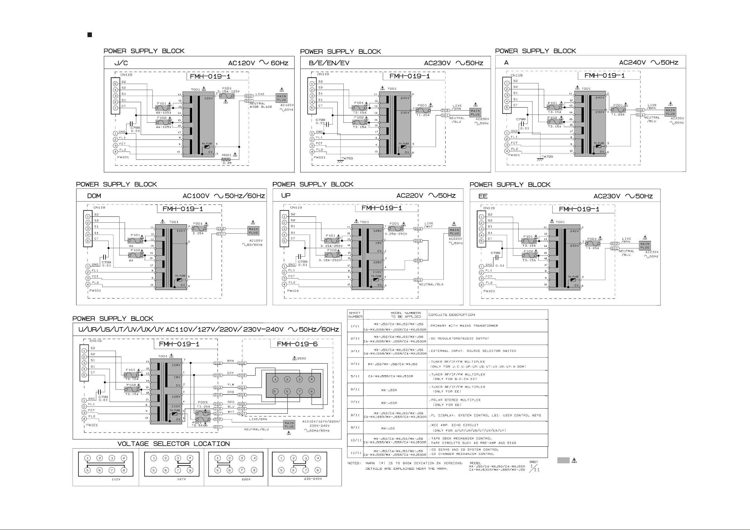
Power T ransformer Section
Parts are safety assurance parts.
When replacing those parts make
sure to use the specified one.
Page 2
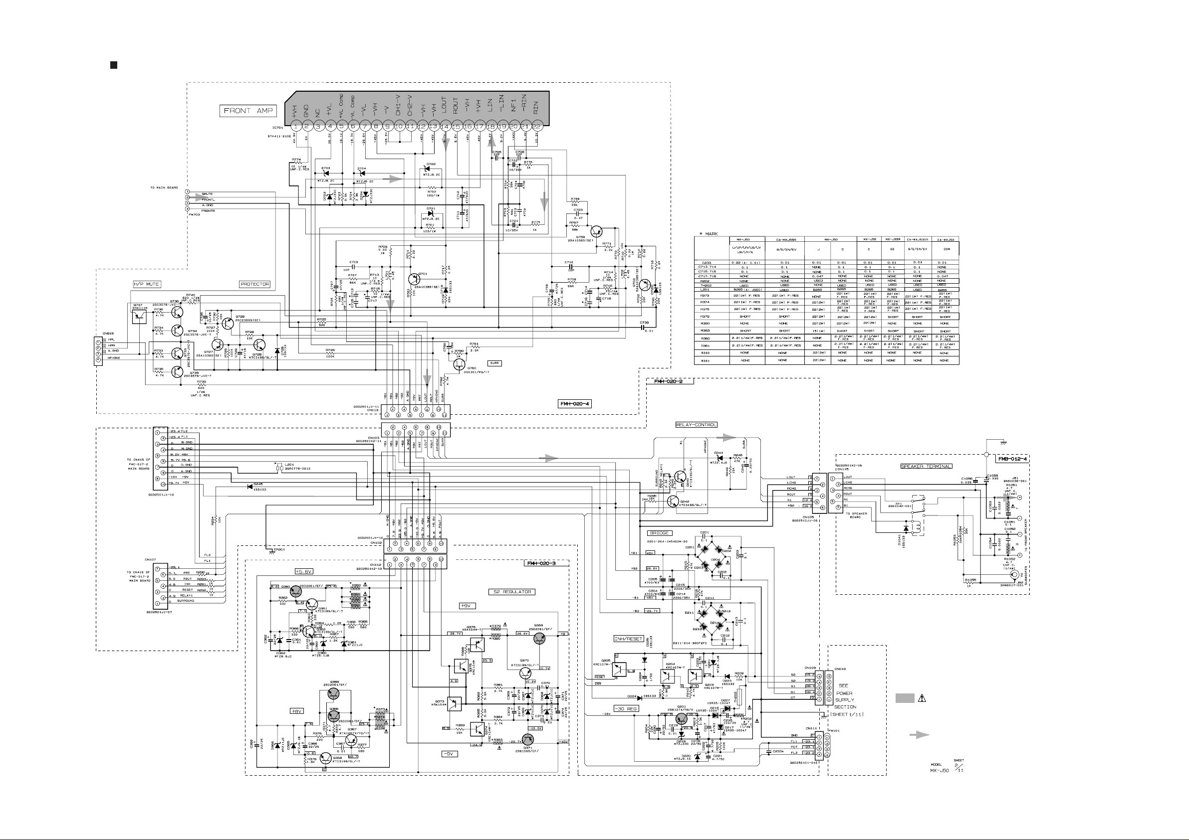
Power Amplifier & Regulator Section
Parts are safety assurance parts.
When replacing those parts make
sure to use the specified one.
MAIN SIGNAL
Page 3
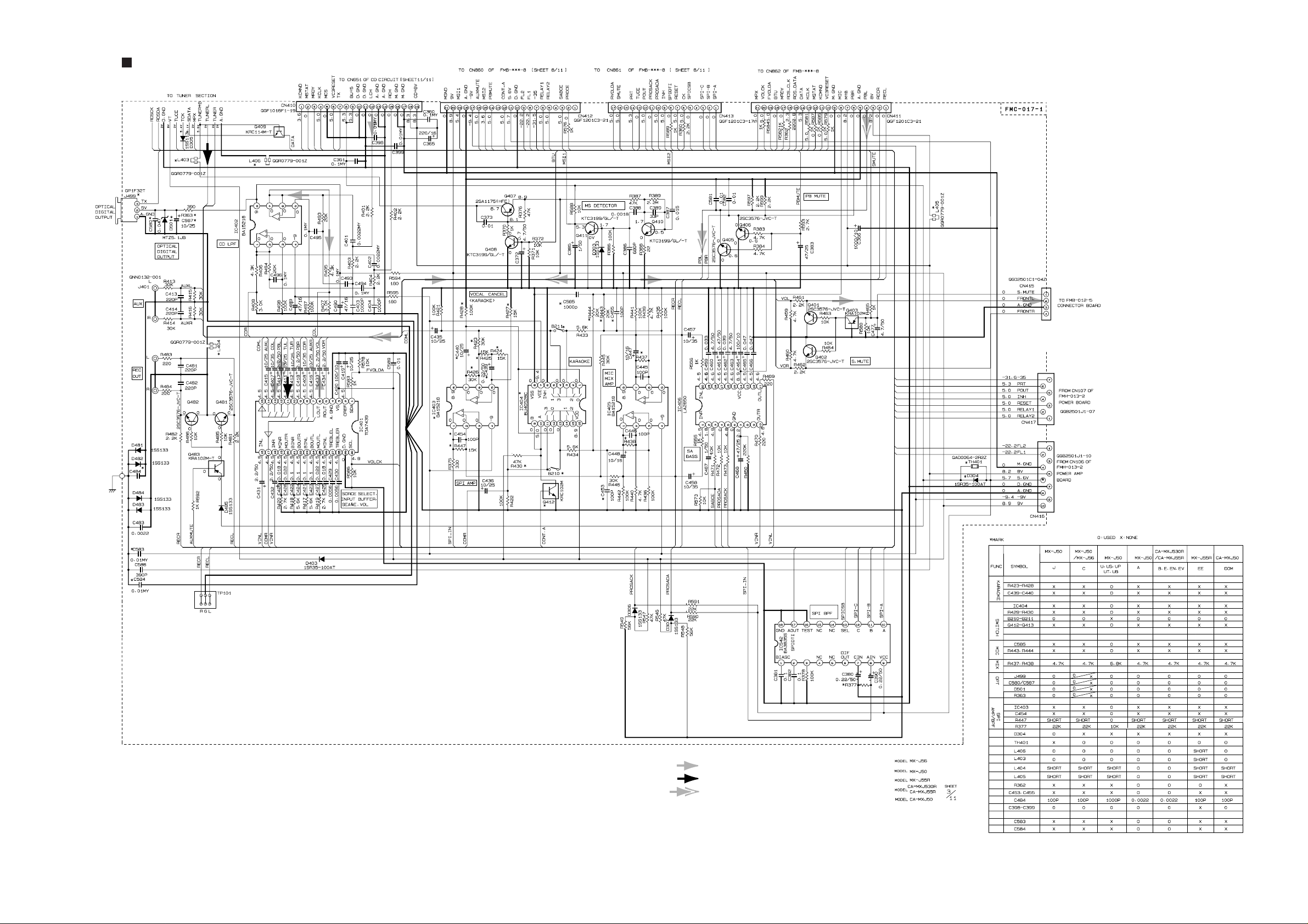
Function & Main Amplifier Section
CD / MAIN SIGNAL
TUNER SIGNAL
TAPE P.B. SIGNAL
Page 4
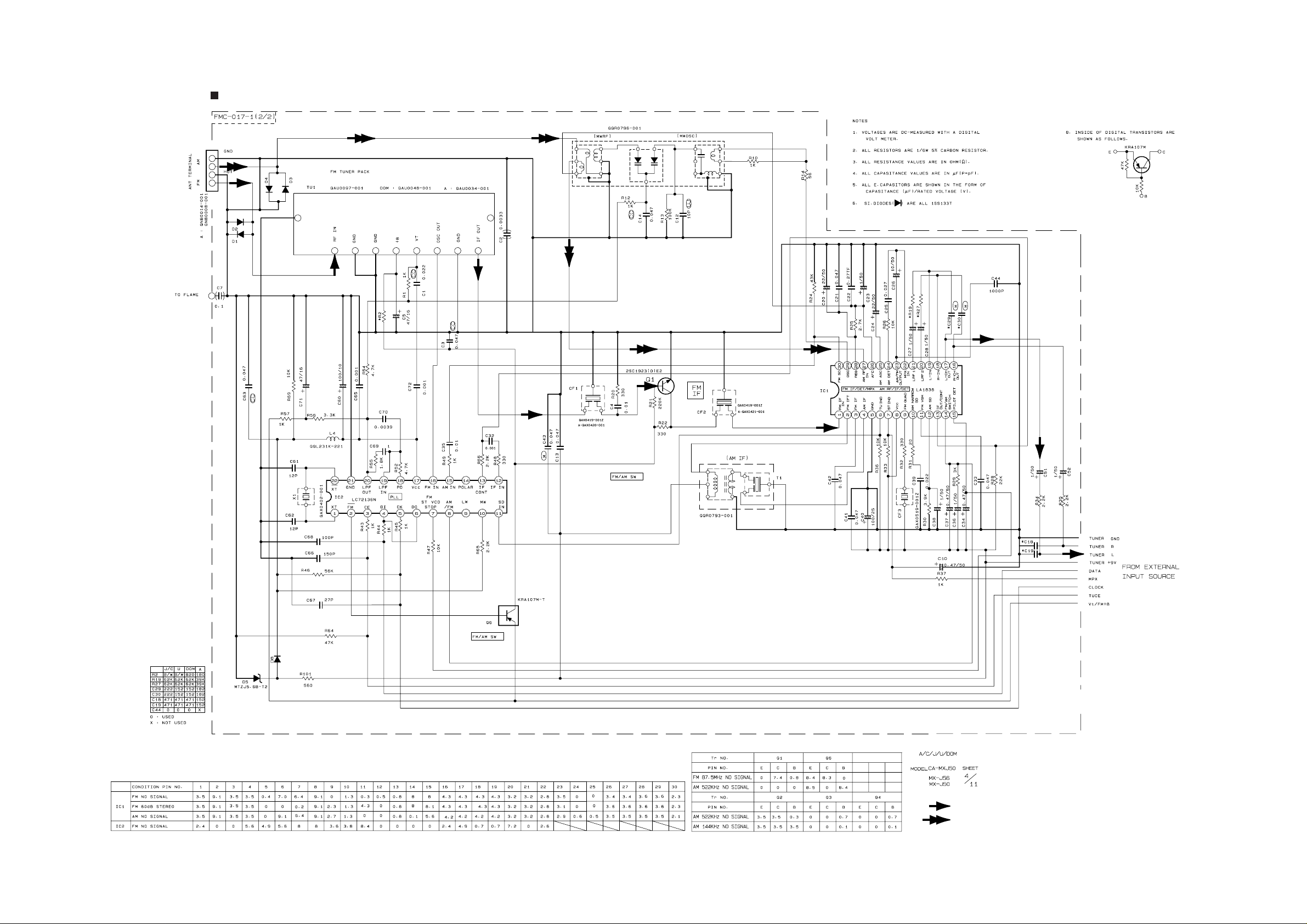
TUNER Section (For Ver.J,C,A,U,DOM)
FM/TUNER MAIN SIGNAL
AM SIGNAL
Page 5
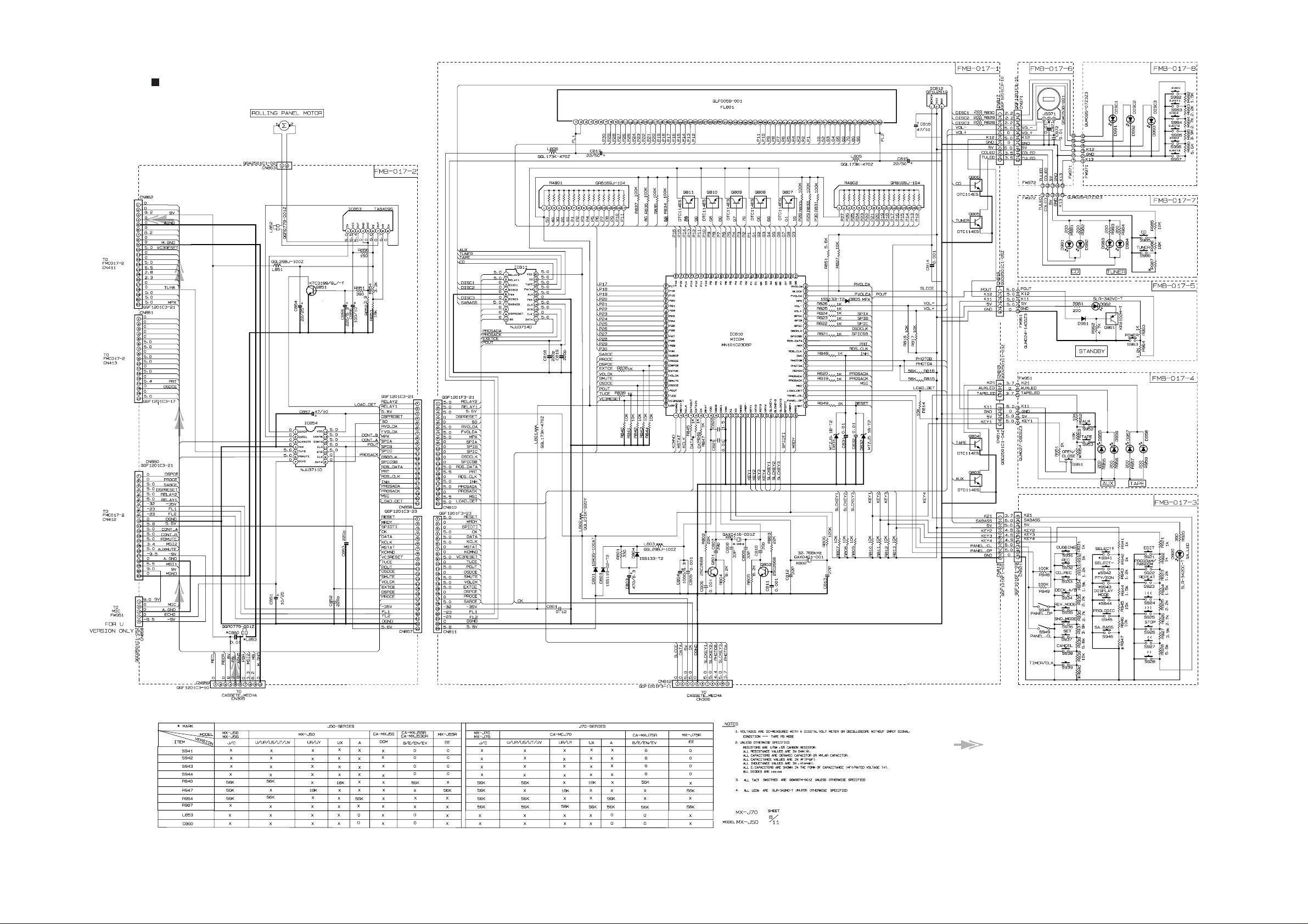
FL Display & System controller Section
RECL
RECR
PBL
PBR
MIC
KCMND
MS TAT
KCLK
DATA
RDS-DATA
RDS-CLK
MRDY
FVOLDA
VOLCK
SPI-A
SPI-B
SPI-C
SPICSB
CK
RESET
SPIDTI
INH
PROSADA
PROSACK
POUT
TUCE
SMUTE
RVOLDA
TAPE P.B. SIGNAL
Page 6
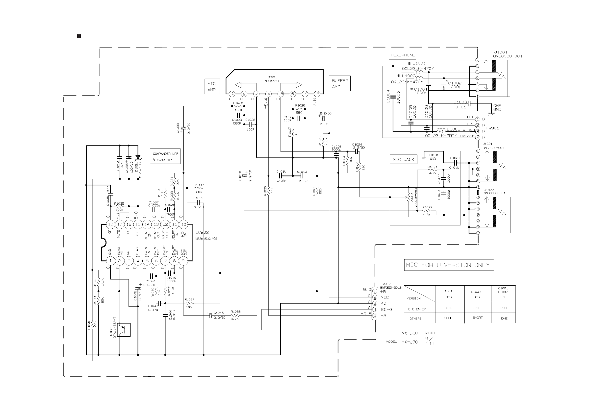
MIC & Headphone Section
Page 7
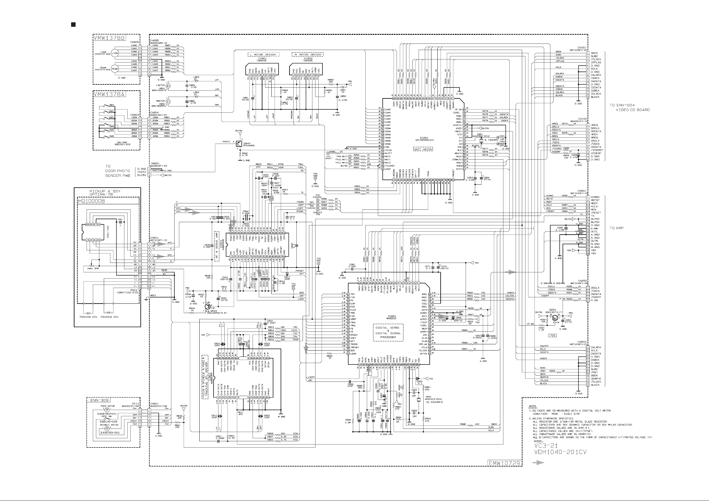
CD Servo & CD Mechanism control section
CD SIGNAL
Page 8
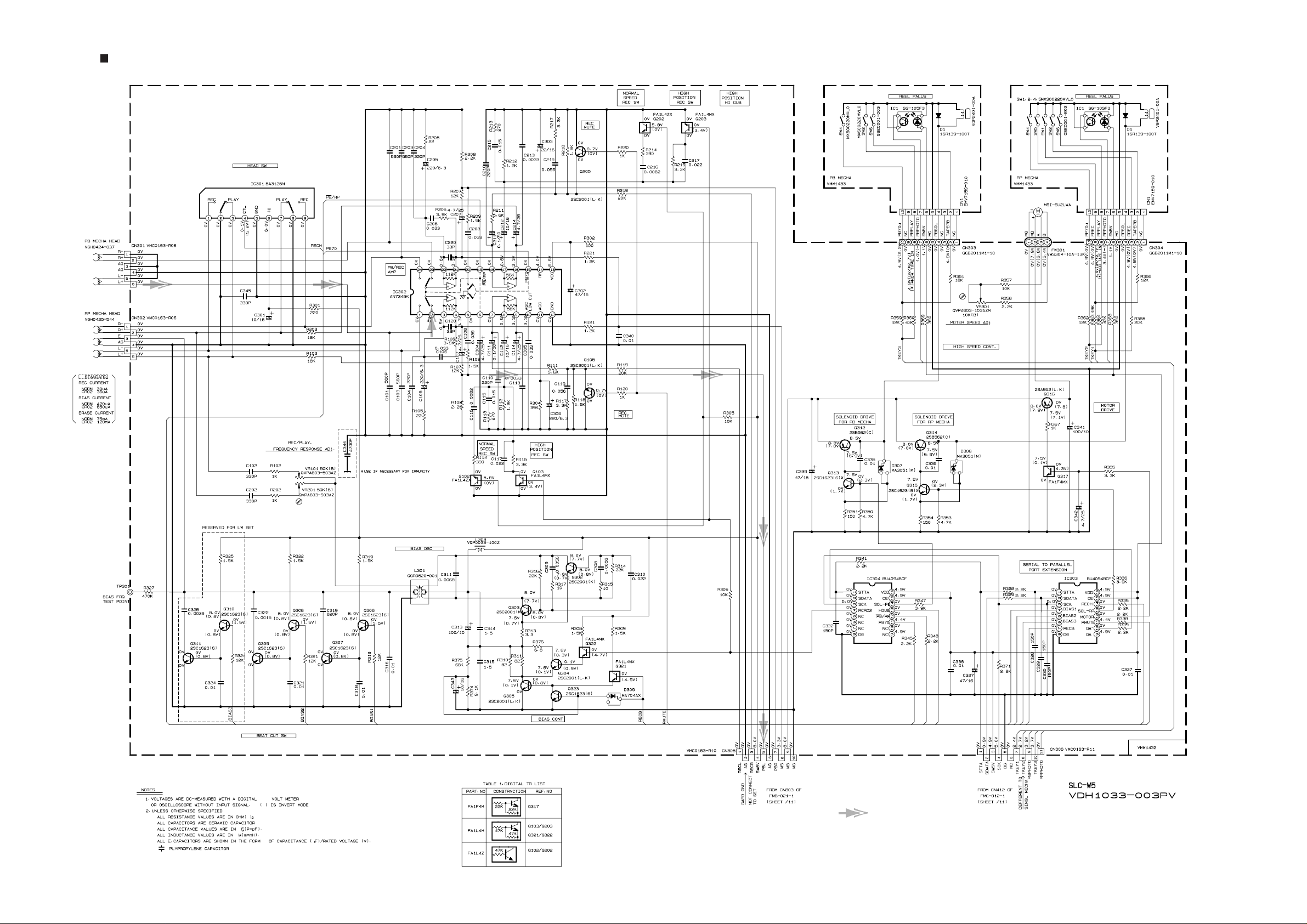
Head amplifier & Mechanism control section
TAPE P.B. SIGNAL
Page 9
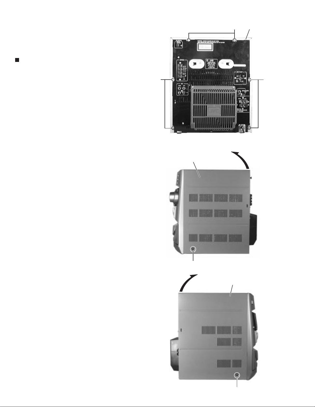
MX-J50
Removal of Main Parts
< Main body >
Removing the Metal Cover (See Fig.1 to 3)
Remove the six A screws attaching the metal cover on
1.
the back of the body.
Remove the two B screws attaching the metal cover on
2.
both sides of the body.
Lift the metal cover on the back of the body and remove it
3.
from the body.
A
A
Metal cover
A
CAUTION: DO NOT break the front panel tab fitted to the
metal cover.
Metal cover
B
Fig.1
Fig.2
2-16
Fig.3
Metal cover
B
Page 10

MX-J50
Removing the CD Changer Mechanism Assembly
(See Fig.4 to 6)
Prior to performing the following procedure, remove the
metal cover.
Disconnect the connector CN410 of the card wire
1.
connecting the CD changer mechanism board to the
main board.
Remove the two C screws on the upper side of the CD
2.
changer assembly and the two D screws on the back of
the rear panel.
Remove the plastic rivet attaching the main board.
3.
Lift and remove the CD changer mechanism assembly on
4.
the back of the body while pulling the rear panel and the
front panel assembly.
* To prevent damage to the CD fitting, be sure to pull the
rear panel and the front panel assembly enough to
remove the CD changer mechanism.
CN410
Main board
Fig.4
D
C
CD changer
assembly
Rear panel
Rear panel
Front panel assembly
Plastic rivet
Fig.5
Main board
Main board
Fig.6
2-17
Page 11

MX-J50
< Front Assembly >
Removing the Front Panel Assembly
(See Fig.7 to 9)
Prior to performing the following procedure, remove the
metal cover and CD changer mechanism assembly.
Disconnect the card wires from connector CN411, CN412
1.
and CN413 on the main board.
Disconnect the flat wire from connector CN703 on the
2.
amplifier board.
Remove the four E screws attaching the front panel
3.
assembly on the bottom of the body.
Release the two joints(a) and (b) on the lower left and
4.
right sides of the body using a screwdriver, and remove
the front panel assembly toward the front.
Main board
Amplifier board
CN413
CN703
CN411
Front panel assembly
CN412
Fig.7
E
2-18
Fig.9a
Joint(a)
Fig.8
Joint(b)
Fig.9b
Page 12

MX-J50
Removing the Rolling panel Panel assembly
(See Fig.10 and 11)
Disconnect the card wires from connector CN817,CN812,
1.
CN951 and CN816 on the upper system control & FL
board and on the rolling panel assembly on the reverse
side of the front panel assembly
Disconnect the card wire from connector CN859 on the
2.
relay board on the back of the rolling panel assembly.
Disconnect the flat wire from connector CN858 on the
3.
relay board. (Only Ver.U type)
Remove the six F screws attaching the stay bracket.
4.
Remove the four G screws attaching the rolling panel
5.
assembly.
Disconnect the flat wire extending from the phones
*
board through the slit of the rolling panel assembly.
CN817
Stay bracket
CN951CN812
CN816
System control & FL board
Fig.10
F
Phones board
Removing the Cassette Mechanism Assembly
(See Fig.12)
1.Prior to performing the following procedure, remove the
rolling panel assembly.
Remove the four H screws and four H1 screws attaching
the cassette mechanism assembly.
H
G
Relay board
G
CN858
G
CN859
Fig.11
H
H1
Fig.12
Cassette mechanism
H1
assembly
2-19
Page 13

MX-J50
Removing the System Control & FL Board
(See Fig.13 and 14)
1.
Disconnect the card wires and flat wires from connector
CN812, CN817, CN816, CN951, CN813, CN810 and
CN811 on the system control & FL board respectively.
Disconnect the flat wire from connector D851 on the relay
2.
board.
Remove the six F screws attaching the stay bracket.
3.
Remove the two I screws attaching the system control &
4.
FL board.
CN817
I
CN812
Stay bracket
System control & FL board
CN810
CN813
Fig.13
CN951
I
CN816
CN811
F
Removing the Relay Board (See Fig.15)
Disconnect the card wires, the 2P harness and the flat
1.
wires from connector CN856, CN857, CN859, CN863,
CN858 (Only Ver.U type) and D851 on the relay board
respectively.
2.
Remove the one screw J attaching the relay board.
3.
Release the five c tabs fitted to the relay board.
J
Relay board
D851
Fig.14
Tab cCN856Tab c
CN859
CN857
CN858
2-20
Tab c
Relay board
D851
Tab c CN863 Tab c
Fig.15
Page 14

MX-J50
Removing Each Board of the Front Panel
Assembly (See Fig.16 and 17)
Disconnect the flat wire from connector CN816 on the
1.
system control & FL board on top of the rolling panel
assembly.
Remove the three K screws attaching the power switch
2.
board.
Remove the two L screws attaching the phones board
3.
together with bracket.
Remove the flat wire extending from the phones
*
board through the slit of the rolling panel assembly.
The flat wire connected with CN858 is removed for U
*
version.
The screw H1 is removed and the earth wire is
*
removed for U version.
Remove the four M screws attaching the CD eject board
4.
and unsolder the flat wire.
Remove the rolling panel assembly.
Pull out the volume knob and nut toward the front.
5.
Remove the two N screws attaching the volume board
6.
and unsolder the flat wire.
CD eject board
M
Unsolder
Unsolder Volume board
Fig.16
Power switch
KM
board
Phones board
CN858
H1
K
L
CN816
L
Remove the three O screws attaching the function board
7.
1 and unsolder the flat wire.
Remove the four P screws attaching the function board 2.
8.
N
Unsolder
O
Function board 1
O
PP
Function
board 2
PP
Fig.17
2-21
Page 15

MX-J50
< Rear Panel Assembly >
Prior to performing the following procedure, remove the
metal cover and the CD changer mechanism assembly.
The following procedure can be performed even if the
front panel assembly is attached.
Removing the Rear Cover (See Fig.18)
1. Remove the two Q screws attaching the rear cover on the
back of the body.
Removing the Rear Panel (See Fig.18 to 21)
Prior to performing the following procedure, remove the
rear cover.
Remove the four R screws attaching the heat sink and
1.
the rear panel.
S
Q
S
S
Rear cover
Rear panel
T
Q
S
S
Fig.18
Rear panel
Remove the ten S screws attaching the rear panel.
2.
Remove the two T screws attaching the voltage selector
3.
and the rear panel. (Only Ver.U type)
Release the two joints(d) and (e) on the lower part of the
4.
rear panel using a screwdriver, and remove the rear
panel toward the rear side.
R
R
Heat sink
Fig.19
2-22
Joint(d)
Joint(e)
Fig.21Fig.20
Page 16

MX-J50
Removing the Main Board (See Fig.22 and 23)
Prior to performing the following procedure, remove the
metal cover, the CD changer mechanism assembly and
the rear panel.
Disconnect the card wires from connector CN411, CN412
1.
and CN413 on the main board and the flat wire from
connector CN415.
Remove the screw U attaching the main board on the
2.
right side of the body.
Disconnect connector CN416 and CN417 under the main
3.
board, and remove the main board upward.
Removing the Rated Voltage Board and Power
Amplifier Board (See Fig.22, 24 and 25)
Prior to performing the following procedure, remove the
metal cover, the CD changer mechanism assembly and
the rear panel.
The following procedure can be performed even if the
front panel assembly is attached.
Disconnect the flat wire from connector CN703 on the
1.
power amplifier board.
CN415
Main board
CN703
CN413
CN411
CN412
Fig.22
Disconnect the flat wire from connector CN415 on the
2.
main board.
Pull out the rated voltage board and the power amplifier
3.
board upward from connector CN102 and CN103 on the
power board respectively.
Remove the two V screws and two W screws attaching
4.
the heat sink together with the heat sink bracket.
Power board
CN105
V
Heat sink
Main boardMain board
CN416
Fig.23
CN417
U
Power amplifier board
Rated voltage board
W
CN102
Rated voltage board
Power amplifier board
CN103
Speaker board
Heat sink bracket
Fig.25Fig.24
2-23
Page 17

MX-J50
Removing the Speaker Board (See Fig.24)
Prior to performing the following procedure, remove the
metal cover, the CD changer mechanism assembly and
the rear panel.
The following procedure can be performed even if the
front panel assembly is attached.
Pull out the speaker board upward from connector
1.
CN105 on the power board.
Power board
CN102
Rated voltage board
Power amplifier board
Fig.24
CN103
CN105
Speaker board
Removing the Power Transformer Board
(See Fig.26)
Prior to performing the following procedure, remove the
metal cover, the CD changer mechanism assembly and
the rear panel.
Disconnect the 5P harness and the flat wire from
1.
connector CN109 and CN111 on the power board.
Remove the four X screws attaching the power
2.
transformer assembly.
Push the cord stopper upward to remove it.
3.
CN111
CN109
Power transformer board
Fig.26
X
X
Cord stopper
2-24
Page 18

Removing the rolling Panel Assembly
(See Fig.27)
1.2.Remove the two Y screws attaching the rolling panel
assembly.
Remove the rolling panel assembly while pulling outward
the left and right hooks attaching the rolling panel
assembly.
MX-J50
Removing the operation switch Board
(See Fig.28 and 29)
Remove the six Z screws attaching the cover and the
1.
bracket.
Release the two f tabs fitted to the bracket, and pull out
2.
the left and right panel holders.
Remove the two A screws attaching the operation switch
3.
board.
Removing the Drive Motor (See Fig.30 and 31)
1.
Remove the two B screws and the two C screw attaching
2.
Pull out the gear shaft A upward.
3.
Remove the motor belt.
Panel holder
Tab f
Rolling panel assembly
Fig.27
Z
Fig.28
Hook
Y
Bracket
Panel holder
Tab f
Cover
operation switch Board
Joint bracket
B C
Fig.30
Joint bracket
Gear shaft A
Fig.29
Fig.31
A
Motor belt
Drive motor
2-25
Page 19

MX-J30/MX-J330/MX-J35R
CD Changer Mechanism Type:VC3 Section
Removing the CD Servo control board
(See Fig.1)
1.Remove the metal cover.
2.Remove the CD changer mechanism assembly.
3.From bottom side the CD changer mechanism assembly,
remove the two screws 1 retaining the CD servo control
board.
4.Absorb the four soldered positions "M" of the right and
left motors with a soldering absorber.
5.Pull out the earth wire on the CD changer mechanism
assembly.
6.The two screws A is removed and C.B.holder is detached.
7.Disconnect the connector CN854 on the CD servo
control board.
8.Disconnect the card wire CN601 and the connector
CN801 on the CD servo control board.
Removing the CD tray assembly
(See Fig.2
Remove the front panel assembly.
1.
Remove the CD changer mechanism assembly.
2.
Remove the CD Servo control board.
3.
From the T.bracket section
4.
section
rod(See Fig.2 and 3).
Remove the screw 2 retaining the Disc stopper
5.
(See Fig.3).
Remove the three screws 3 retaining the T.bracket
6.
(See Fig.3).
Remove the screws 4 retaining the clamper assembly
7.
(See Fig.3).
From the left side face of the chassis assembly, remove
8.
the one screw 5 retaining both of the return spring and
lock lever(See Fig. 4).
By removing the pawl at the section
9.
return spring, dismount the return spring(See Fig.4).
10.
Remove the three lock levers(See Fig.4).
T.Braket
C , remove both of the edges fixing the
B and clamper base
D fixing the
Disc stopper
4)
B
1
M
M
CN854
1
CN651
CD servo control board
CN801
CN601
Earth
wire
A
A
C.B.Holder
Fig.1
Clamper base
Rod
C
T.Braket
Fig.2
3
B
C
Clamper ass'y
Fig.3
2
3
Lod stopper
(C/J version only)
3
4
Lock lever
Fig.4
D
Return spring
5
2-17
Page 20

MX-J30/MX-J330/MX-J35R
11.
Check whether the lifter unit stopper has been caught
into the hole at the section
as shown in Fig.5.
12.
Make sure that the driver unit elevator is positioned as
shown in Fig.6 from to the second or fifth hole on the
left side face of the CD changer mechanism assembly.
[Caution]
13.
14.
15.
Chassis assembly
In case the driver unit elevator is not at above
position, set the elevator to the position as
shown in Fig.7 by manually turning the pulley
gear as shown in Fig.8.
Manually turn the motor pulley in the clockwise
direction until the lifter unit stopper is lowered from the
section
Pull out all of the three stages of CD tray assembly in
the arrow direction
(See Fig.6).
At the position where the CD tray assembly has
stopped, pull out the CD tray assembly while pressing
the two pawls
assembly(See Fig.9). In this case, it is easy to pull out
the assembly when it is pulled out first from the stage
CD tray assembly.
E of CD tray assembly(See Fig.8).
G and G on the back side of CD tray
E of CD tray assembly
F until these stages stop
Fig.5
Stopper
E
CD tray
assembly
Refer to Fig.7
Pawl
CD tray assembly
G
F
Drive unit of elevator
Fig.7Fig.6
CD tray assembly
2-18
Pulley gear
Motor pulley
Fig.8
Pawl ,
G
Fig.9
G'
Page 21

MX-J30/MX-J330/MX-J35R
Removing the CD loading mechanism
assembly(See Fig.10)
1.2.While turning the cams R1 and R2 assembly in the
arrow direction
loading mechanism assembly to the position shown in
Fig.10.
Remove the four screws 6 retaining the CD loading
mechanism assembly.
H align the shaft I of the CD
Removing the CD traverse mechanism
(See Fig.11 and 12 )
For dismounting only the CD traverse mechanism
1.
without removing the CD loading mechanism assembly,
align the shaft
assembly to the position shown Fig.11 while turning the
cam R1 and R2 assembly in the arrow direction
By raising the CD loading mechanism assembly in the
2.
arrow direction
lifter unit
Cam R1, R2 assembly
J of the CD loading mechanism
K .
L , remove the assembly from the
Cams R1, R2 assembly
Arrow
H
I
6
6
CD loading mechanism assembly
Fig.10
6
6
CD traverse mechanism
Arrow
K
J
Fig.11
Removing the CD pick unit
(See Fig.13 )
Move the cam gear in the arrow direction a . Then, the
1.
CD pickup unit will be moved in the arrow direction b .
According to the above step, shift the CD pickup unit to
2.
the center position.
While pressing the stopper retaining the shaft in the
3.
arrow direction c , pull out the shaft in the arrow
direction d .
After dismounting the shaft from the CD pickup unit,
4.
remove the CD pickup unit
Lifter unit
c
Shaft
Fig.12
CD Pickup unit
b
a
Shaft
d
Arrow
CD loading
mechanism
Shaft
Cam gear
L
Stopper
Fig.13
Stopper
2-19
Page 22

MX-J30/MX-J330/MX-J35R
Removing the cam unit
(See Fig.14
1.
Remove the CD loading mechanism assembly.
2.
While turning the cam gear L, align the pawl
position of the drive unit to the notch position(Fig.16) on
the cam gear L.
Pull out the drive unit and cylinder gear(See Fig.17).
3.
While turning the cam gear L, align the pawl
4.
position of the select lever to the notch position(Fig.18)
on the cam gear L.
Remove the four screws 9 retaining the cam unit(cam
5.
gear L and cams R1/R2 assembly)(See Fig.18).
17 )
N
O
Chassis assembly
CN801
CN802
Fig.14
Drive unit
Cylinder gear
Tray select
switch board
CN804
Drive unit
N
8
Cam gear L
Cam gear L
Fig.15
Cams R1, R2 assembly
9
Cam unit
2-20
Fig.16
9
9
O
Select lever
Fig.17
Page 23

MX-J30/MX-J330/MX-J35R
Removing the actuator motor and belt
(See Fig.18
1.
Remove the two screws 10 retaining the gear bracket
(See Fig.19).
2.
While pressing the pawl
the arrow direction, remove the gear bracket
(See Fig.19).
From the notch
3.
fixing the edge of gear bracket, remove and take out the
gear bracket(See Fig. 20).
4.
Remove the belts respectively from the right and left
actuator motor pulleys and pulley gears(See Fig. 19).
5.
After turning over the chassis assembly, remove the
actuator motor while spreading the four pawls
fixing the right and left actuator motors in the arrow
direction(See Fig. 21).
[Note]
When the chassis assembly is turned over under
the conditions wherein the gear bracket and belt
have been removed, then the pulley gear as well
as the gear, etc. constituting the gear unit can
possibly be separated to pieces. In such a case,
assemble these parts by referring to the assembly
and configuration diagram in Fig. 22.
Q section on the chassis assembly
P fixing the gear bracket in
21)
R
Pulley gear
Gear bracket
Belt
Motor pulley
10
Fig.18
Actuator motor
Pulley gear
Belt
Motor pulley
10
Pawl
P
Chassis assembly
Q
Gear bracket
Fig.19
Assembly and Configuration Diagram
Pulley gear
R
R
Fig.20
Pulley gear
Gear B
Cylinder gear
Gear B
Gear C
Select gear
Gross gear L
Fig.21
Gross gear U
Gear C
2-21
Page 24

MX-J30/MX-J330/MX-J35R
Removing the cams R1/R2 assembly
and cam gear L(See Fig.22)
Remove the slit washer fixing the cams R1 and R2
1.
assembly.
By removing the two pawls
2.
separate R2 from R1.
3.
Remove the slit washer fixing the cam gear L.
4.
Pull out the cam gear L from the C.G. base assembly.
S fixing the cam R1,
Removing the C.G. base assembly
(See Fig.22 and 23)
Remove the three screws 11 retaining the C.G. base
assembly.
[Caution]
To reassemble the cylinder gear, etc.with the
cam unit (cam gear and cans R1/R2 assembly),
gear unit and drive unit, align the position of the
pawl
N on the drive unit to that o f the notch
on the cam gear L. Then, make sure that the
gear unit is engaged by turning the cam gear L
(See Fig. 24).
Slit washer
Cam gear L
11
Slit washer
Cam R2
Pawl
S
Cam R1
Cam switch board
C.G. base assembly
Pawl
S
Notch
Pawl
N
Cylinder
gear
Drive unit
Fig.22
Cam gear L
Cam R1, R2 assembly
Gear unit
Gear bracket
Fig.23
2-22
Page 25

MX-J30/MX-J330/MX-J35R
< Cassette Mechanism Section >
Removing the Playback,Recording and Eraser
Heads
1. While shifting the trigger arms seen on the right
side of the head mount in the arrow direction,turn
the flywheel R in counterclockwise direction until
the head mount has gone out with a click
(See Fig 1).
2. When the flywheel R is rotated in counterclockwise
direction, the playback head will be turned in
counterclockwise direction from the position in
Fig 2 to that in Fig 3.
3. At this position, disconnect the flexible P.C.board
(outgoing from the playback head) from the
connector CN301 on the head amp. and mechanism
control P.C. board.
4. After dismounting the FPC holder,remove the
flexible P.C.board.
5. Remove the flexible P.C.board from the chassis
base.
6. Remove the spring "a" from behind the playback
head.
7. Loosen the reversing azimuth screw retaining the
playback head.
8. Take out the playback head from the front of the
head mount.
9. The recording and eraser heads should also be
removed similarly according to Steps 1~8 above.
Reassembling the Playback, Recording and
Eraser Heads
Cassette mechanism
Playback/Recording &
eraser head
Flexible
board
CN31
Head amplifier & mechanism
control P.C. board
Flywheel R
Trigger armHead mount
(Mechanism A side)
Spring "a"
Trigger arm
Flywheel R
(Mechanism A side)
1. Reassemble the playback head from the front of
the head mount to the position as shown in Fig 3.
2. Fix the reversing azimuth screw.
3. Set the spring a from behind the playback head.
4. Attach the flexible P.C.board to the chassis base,
and fix it with the FPC holder as shown in Fig 3.
5. The recording and eraser heads should also be
reassembled similarly according to Steps 1~4
above.
Playback head
Spring "a"
FPC holder
Reversing azimuth
screw
Head
mount
Flexible
board
CN301
Head amplifier &
mechanism control
P.C. board
(Mechanism B side)
2-23
Page 26

MX-J30/MX-J330/MX-J35R
Removing the head Amp.and Mechanism
Control P.C.Board (See Fig 4)
1.Remove the cassette mechanism assembly.
2.After turning over the cassette mechanism
assembly,remove the five screws "A" retaining
the head amp. and mechanism control P.C.
board
3.Disconnect the connectors CN303 and CN304
on the P.C.Board and the connectors CN1 on
both the right and left side reel pulse
P.C.Boards.
4.When necessary, remove the 4pin parallel
wire soldered to the main motor
Removing the Capstan Motor Assembly
1.Remove the six screws "B" retaining capstan
motor assembly (See Fig 5).
2.While raising the capstan motor, remove the
capstan belts A and B respectively from the
motor pulley (See Fig 6).
A
Flexible
board
Head amplifier &
mechanism control board
AA
CN304
CN302 CN301
Flexible
board
BB
CN303
Capstan motor
assembly
AA
Caution 1: Be sure to handle the capstan
belts so carefully that these belts
will not be stained by grease and
other foreign matter. Moreover,
these belts should be hand while
referring to the capstan belt
hanging method.
Capstan
belt A
Capstan
belt B
Capstan
belt A
BBBB
Capstan motor
Capstan
belt B
Motor pulley
2-24
Page 27

MX-J30/MX-J330/MX-J35R
Removing the Capstan Motor (See Fig 8)
From the joint bracket, remove the two screws "C"
retaining the capstan motor.
Removing the Flywheel (See Fig 9.10)
1.Remove the head amp. and mechanism control
P.C.Board.
2.Remove the capstan motor assembly.
3.After turning over the cassette mechanism, remove
the slit washers "a" and "b" fixing the capstan shafts
R and L, and pull out the flywheels R and L respectively
from behind the cassette mechanism.
C
Capstan motor
Joint
bracket
C
Flywheel R Flywheel L
Flywheel R Flywheel L
Removing the Reel Pulse P.C.Board and Solenoid
(See Fig 11)
1.Remove the five pawls (c,d,e,f,g) retaining
the reel pulse P.C.Board.
2.From the surface of the reel pulse P.C.Board parts,
remove the two pawls "h" and "i" retaining the solenoid.
hi
Solenoid
c
a
Slit
washer "a"
d
b
Slit
washer "b"
g
f
e
Reel pulse board
Solenoid
2-25
 Loading...