

Page 1
SERVICE MANUAL
COMPACT COMPONENT SYSTEM
MX-J100
MX-J100
POWER
TIMER
SLEEP
ON/OFF
SOUND
ACTIVE
PROGRAM
REPEAT
MODE
BASS EX.
/SET
TAPEA/B
CD
TUNING MODE FM MODE
TAPE
FM/AM AUX
CD
DISC SKIP
VOL.
+
FADE
MUTING
VOL.
–
RM–SMXJ100J
REMOTE CONTROL
Contents
SP-MXJ100
COMPACT
DIGITAL AUDIO
CA-MXJ100
STANDBY
POWER
COUNTER
CLOCK/TIMER
RESET
DEMO
ACTIVE BASS EX. SOUND MODE
PROGRAM/SET
PHONES
REPEAT
COMPU
PLAY
CONTROL
FULL-LOGIC CONTROL
CD1CD2CD
PLAY & EXCHANGER
AUX FM/AM
CD TAPE
-
TUNING TUNING +
PRESET
+
–
PLAY REC/PLAY
CD SYNCHRO RECORDING
SP-MXJ100
OPEN / CLOSE
DISC CHANGE
3
COMPACT
DIGITAL AUDIO
VOLUME
+
–
CD REC
START
TAPE A/B
REC/PAUSE
A B
DUBBING
EJECTEJECT
Area Suffix
J
C
U.S.A.
Canada
Safety precautions
Important for laser products
Preventing static electricity
Disassembly method
Adjustment method
COPYRIGHT 2000 VICTOR COMPANY OF JAPAN, LTD.
1-2
1-3
1-4
1-5
1-19
Flow of functional operation
until TOC read
Maintenance of laser pickup
Replacement of laser pickup
Description of major ICs
1-23
1-24
1-24
1-25
No.20817
Jun. 2000
Page 2
MX-J100
Safety precautions
1. This design of this product contains special hardware and many circuits and components specially
for safety purposes. For continued protection, no changes should be made to the original design
unless authorized in writing by the manufacturer. Replacement parts must be identical to those
used in the original circuits. Services should be performed by qualified personnel only.
2. Alterations of the design or circuitry of the product should not be made. Any design alterations of
the product should not be made. Any design alterations or additions will void the manufacturer`s
warranty and will further relieve the manufacture of responsibility for personal injury or property
damage resulting therefrom.
3. Many electrical and mechanical parts in the products have special safety-related characteristics.
These characteristics are often not evident from visual inspection nor can the protection afforded
by them necessarily be obtained by using replacement components rated for higher voltage,
wattage, etc. Replacement parts which have these special safety characteristics are identified in
the Parts List of Service Manual. Electrical components having such features are identified by
shading on the schematics and by ( ) on the Parts List in the Service Manual. The use of a
substitute replacement which does not have the same safety characteristics as the recommended
replacement parts shown in the Parts List of Service Manual may create shock, fire, or other
hazards.
4. The leads in the products are routed and dressed with ties, clamps, tubings, barriers and the
like to be separated from live parts, high temperature parts, moving parts and/or sharp edges
for the prevention of electric shock and fire hazard. When service is required, the original lead
routing and dress should be observed, and it should be confirmed that they have been returned
to normal, after re-assembling.
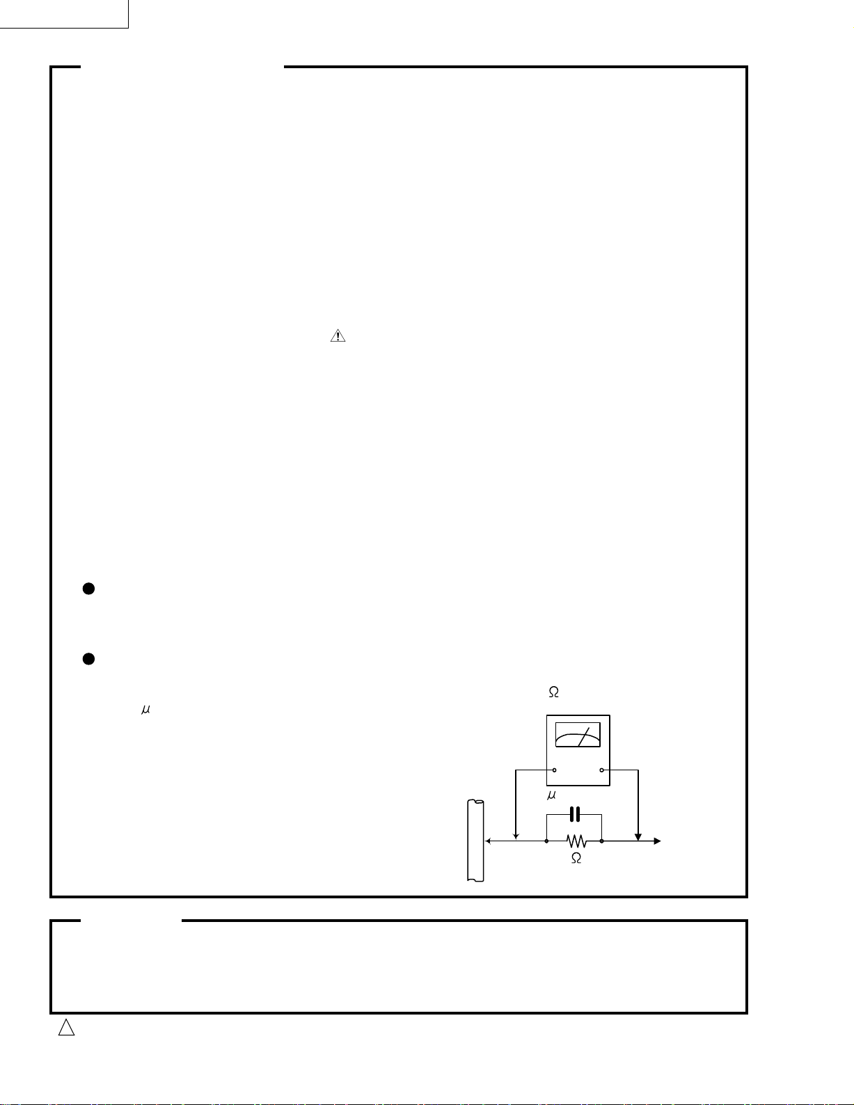
5. Leakage current check (Electrical shock hazard testing)
After re-assembling the product, always perform an isolation check on the exposed metal parts
of the product (antenna terminals, knobs, metal cabinet, screw heads, headphone jack, control
shafts, etc.) to be sure the product is safe to operate without danger of electrical shock.
Do not use a line isolation transformer during this check.
Plug the AC line cord directly into the AC outlet. Using a "Leakage Current Tester", measure
the leakage current from each exposed metal parts of the cabinet , particularly any exposed
metal part having a return path to the chassis, to a known good earth ground. Any leakage
current must not exceed 0.5mA AC (r.m.s.)
Alternate check method
Plug the AC line cord directly into the AC outlet. Use an AC voltmeter having 1,000 ohms
per volt or more sensitivity in the following manner. Connect a 1,500 10W resistor paralleled by
a 0.15 F AC-type capacitor between an exposed
metal part and a known good earth ground.
Measure the AC voltage across the resistor with the
AC voltmeter.
Move the resistor connection to each exposed metal
part, particularly any exposed metal part having a
return path to the chassis, and measure the AC
voltage across the resistor. Now, reverse the plug in
the AC outlet and repeat each measurement. Voltage
measured any must not exceed 0.75 V AC (r.m.s.).
This corresponds to 0.5 mA AC (r.m.s.).
0.15 F AC TYPE
1500 10W
Good earth ground
AC VOLTMETER
(Having 1000
ohms/volts,
or more sensitivity)
Place this
probe on
each exposed
metal part.
Warning
1. This equipment has been designed and manufactured to meet international safety standards.
2. It is the legal responsibility of the repairer to ensure that these safety standards are maintained.
3. Repairs must be made in accordance with the relevant safety standards.
4. It is essential that safety critical components are replaced by approved parts.
5. If mains voltage selector is provided, check setting for local voltage.
Burrs formed during molding may be left over on some parts of the chassis. Therefore,
pay attention to such burrs in the case of preforming repair of this system.
1-2
CAUTION
!
Page 3

Important for laser products
MX-J100
1.CLASS 1 LASER PRODUCT
2.DANGER : Invisible laser radiation when open and inter
lock failed or defeated. Avoid direct exposure to beam.
3.CAUTION : There are no serviceable parts inside the
Laser Unit. Do not disassemble the Laser Unit. Replace
the complete Laser Unit if it malfunctions.
4.CAUTION : The compact disc player uses invisible laser
radiation and is equipped with safety switches which
prevent emission of radiation when the drawer is open and
the safety interlocks have failed or are de
feated. It is dangerous to defeat the safety switches.
5.CAUTION : If safety switches malfunction, the laser is able
to function.
6.CAUTION : Use of controls, adjustments or performance of
procedures other than those specified herein may result in
hazardous radiation exposure.
CAUTION
Please use enough caution not to
see the beam directly or touch it
in case of an adjustment or operation
check.
1-3
Page 4
MX-J100
Preventing static electricity
1. Grounding to prevent damage by static electricity
Electrostatic discharge (ESD), which occurs when static electricity stored in the body, fabric, etc. is discharged,
can destroy the laser diode in the traverse unit (optical pickup). Take care to prevent this when performing repairs.
2. About the earth processing for the destruction prevention by static electricity
In the equipment which uses optical pick-up (laser diode), optical pick-up is destroyed by the static electricity of
the work environment.
Be careful to use proper grounding in the area where repairs are being performed.
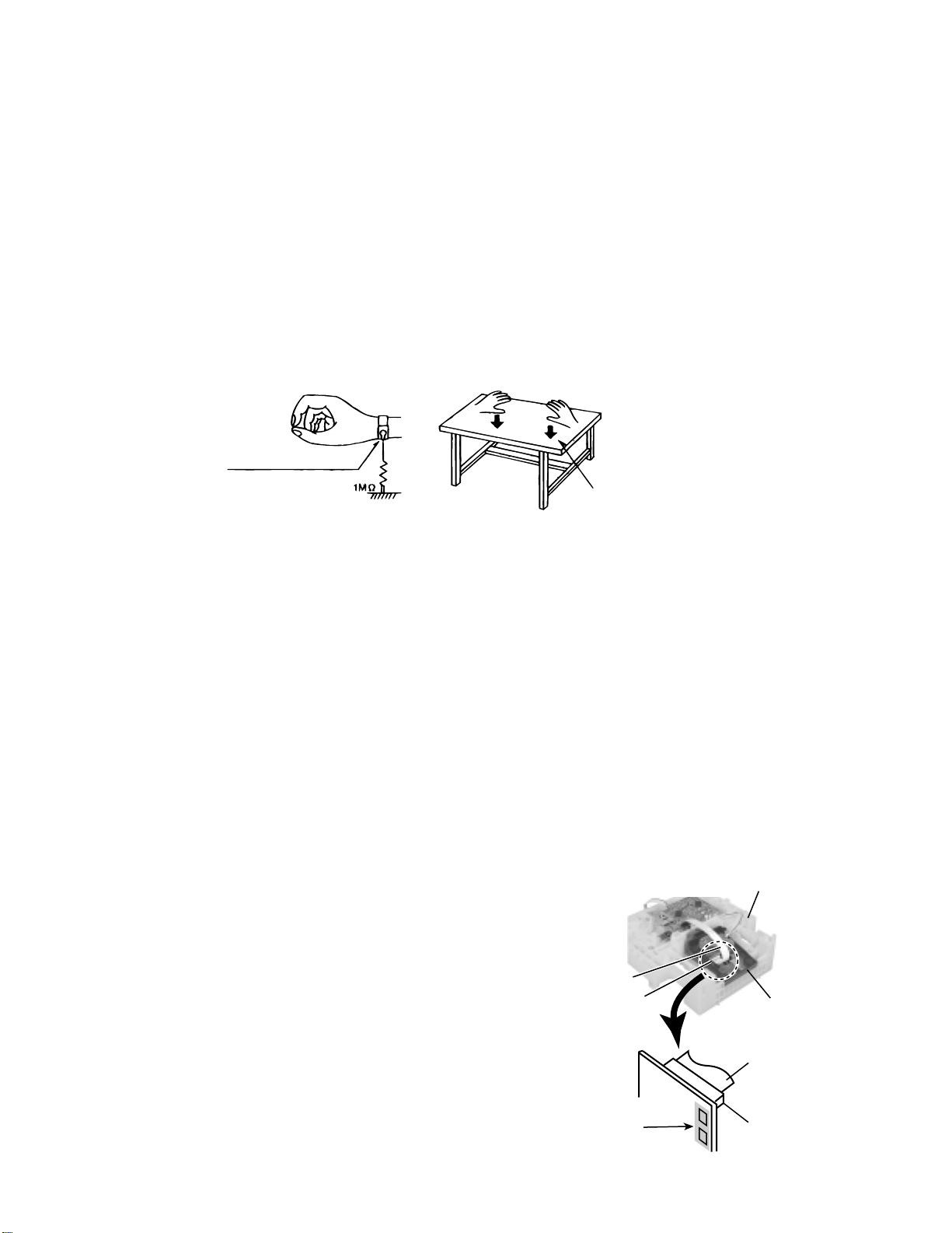
2-1 Ground the workbench
Ground the workbench by laying conductive material (such as a conductive sheet) or an iron plate over
it before placing the traverse unit (optical pickup) on it.
2-2 Ground yourself
Use an anti-static wrist strap to release any static electricity built up in your body.
(caption)
Anti-static wrist strap
Conductive material
(conductive sheet) or iron plate
3. Handling the optical pickup
1. In order to maintain quality during transport and before installation, both sides of the laser diode on the
replacement optical pickup are shorted. After replacement, return the shorted parts to their original condition.
(Refer to the text.)
2. Do not use a tester to check the condition of the laser diode in the optical pickup. The tester's internal power
source can easily destroy the laser diode.
4. Handling the traverse unit (optical pickup)
1. Do not subject the traverse unit (optical pickup) to strong shocks, as it is a sensitive, complex unit.
2. Cut off the shorted part of the flexible cable using nippers, etc. after replacing the optical pickup. For specific
details, refer to the replacement procedure in the text. Remove the anti-static pin when replacing the traverse
unit. Be careful not to take too long a time when attaching it to the connector.
3. Handle the flexible cable carefully as it may break when subjected to strong force.
4. It is not possible to adjust the semi-fixed resistor that adjusts the laser power. Do not turn it
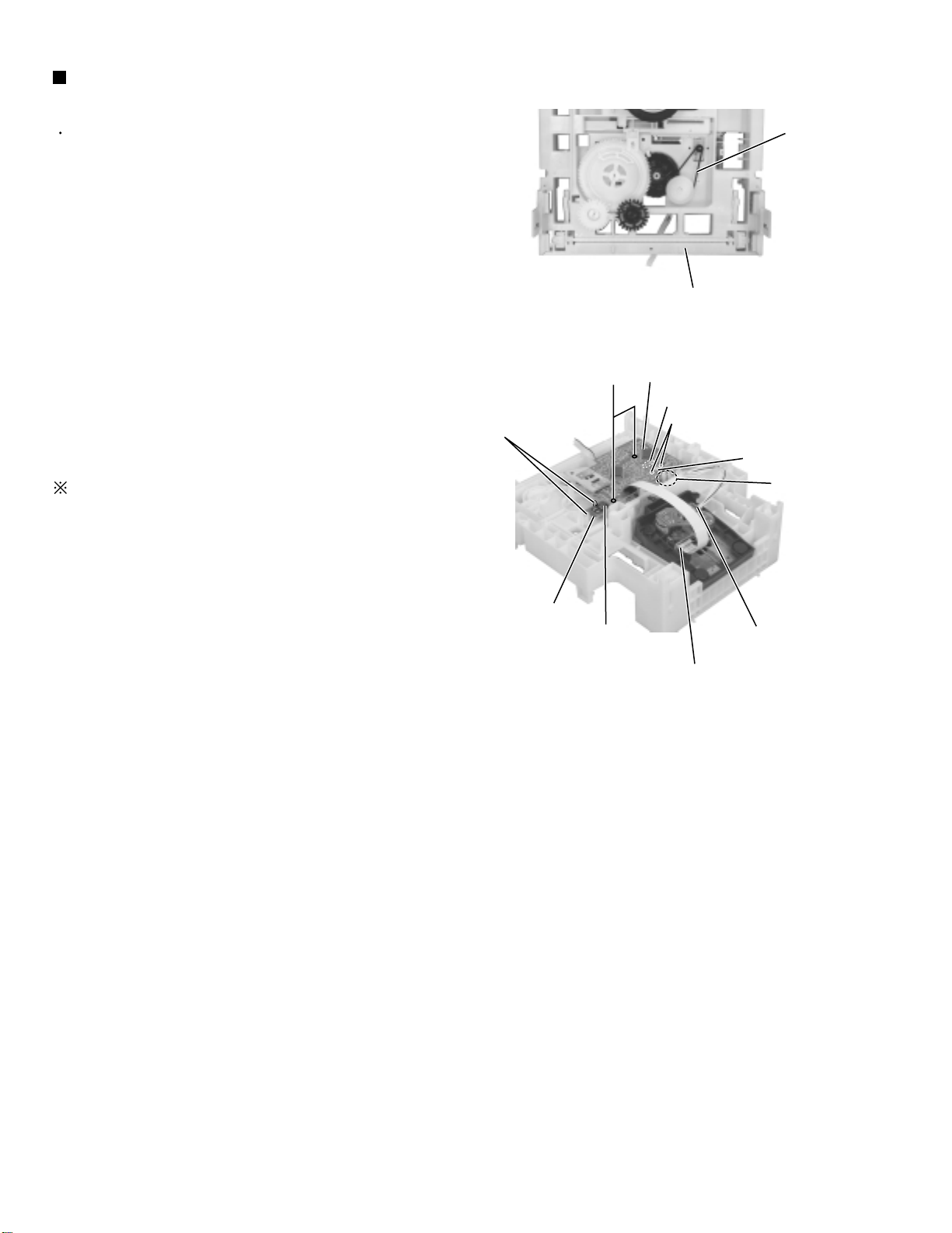
Attention when CD mechanism assembly is decomposed
*Please refer to "Disassembly method" in the text for pick-up and how to
detach the CD mechanism assembly.
CD changer unit
1. Remove the CD changer unit.
2. Remove the CD changer mechanism.
3. Solder is put up before the card wire is removed from the pickup unit
connector on the CD mechanism assembly.
(When the card wire is removed without putting up solder, the CD pick-up
assembly might destroy.)
4. Please remove solder after connecting the card wire with the pickup unit
connector when you install picking up in the substrate.
1-4
Card wire
Picup unit
connector
Soldering
Fig.2
Fig.1
CD changer
mechanism
Card wire
Picup unit
connector
Page 5
MX-J100
Disassembly method
<Main body>
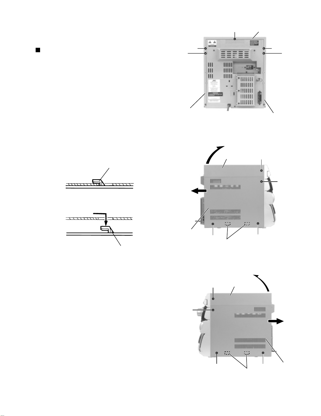
Removing the top cover and the side
covers (See Fig.1 to 3)
1.
Remove the three screws A on the back of the body
and the two screws B on both sides of the body.
2.
Remove the top cover upward from behind.
3.
Remove the two screws C attaching the side covers
on the back of the body and the six screws D on
both sides.
4.
Slide the right and left covers backward and unhook
the two hooks a in the lower part of the side covers
as shown in Fig.2-2.
Hook
A
C
Side cover(L)
A
Fig.1
Top cover
Top cover
A
C
Side cover(R)
B
Hook
Side cover(R)
D
D
B
Hooks a
Fig.2Fig.2-2
Top cover
D
D
D
Hooks a
Fig.3
Side cover(L)
D
1-5
Page 6
MX-J100
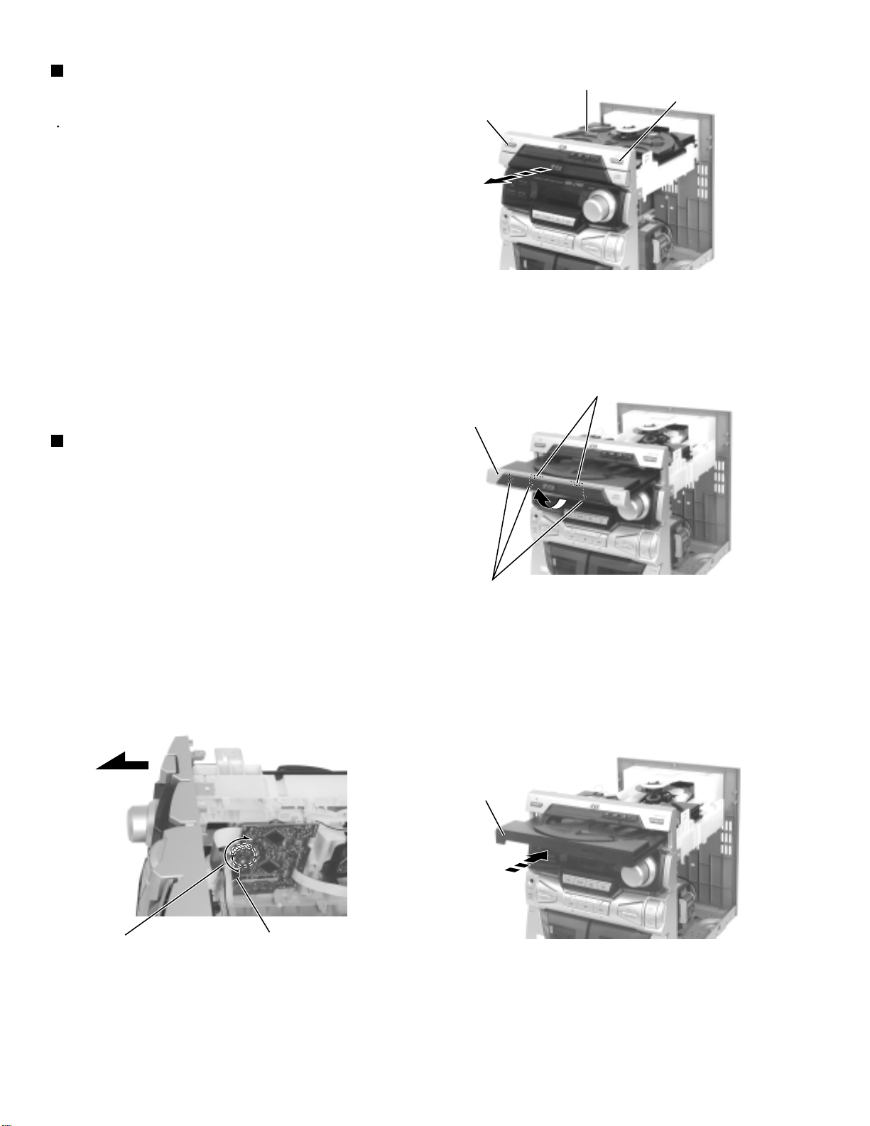
Removing the CD Tray fitting
(See Fig. 4 to 6)
Prior to performing the following procedure, remove
the top cover and the side covers.
ATTENTION:
Be sure to remove the CD tray fitting
before removing the CD changer unit.
1.
Press the POWER button. Press the OPEN/CLOSE
button to eject the CD tray.
2.
Move the CD tray fitting upward and release the joint
b.
3.
Press the OPEN/CLOSE button to insert the tray.
Removing the CD Tray fitting
(See Fig. 5 to 7)
CD tray
OPEN/CLOSE button
POWER button
Fig.4
Joint b
CD tray fitting
- How to eject the CD tray without turning on power -
1.
Turn the black loading pulley gear marked c from the
back of the CD changer unit as shown in Fig.7 and
draw the CD tray toward the front.
2.
Move the CD tray fitting upward and release the joint
b.
3.
Push and insert the CD tray manually.
Joint b
Fig.5
CD tray
Marked c
Loading pulley gear
1-6
This slot of the board.
Fig.7
Fig.6
Page 7
MX-J100
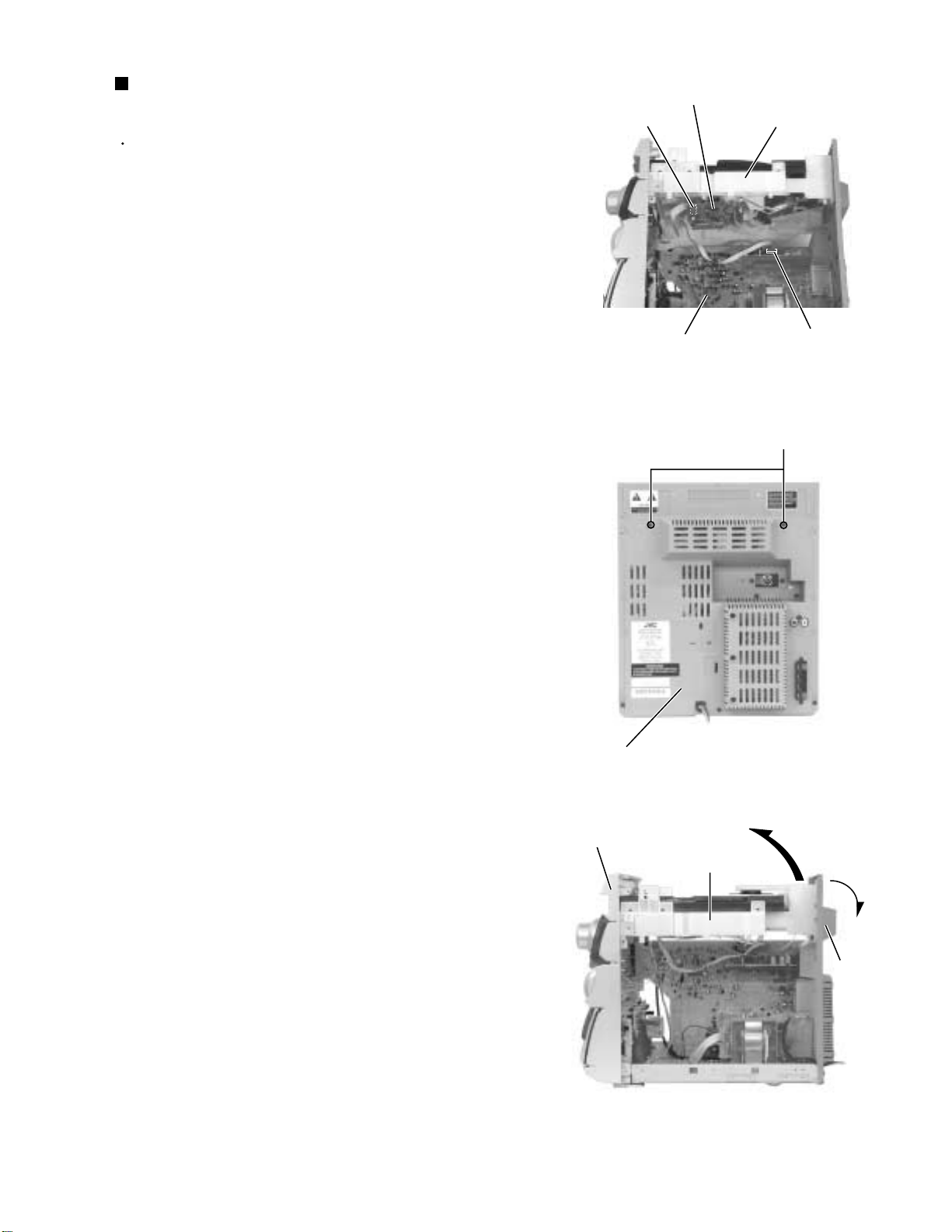
Removing the CD changer unit
(See Fig.8 to 10)
Prior to performing the following procedure, remove
the top cover, the side covers and the CD Tray
fitting.
1.
Disconnect the card wire from connector SCW1 of
the CD servo board on the back of the CD changer
unit.
2.
Disconnect the harness from connector FW2 on the
inner side of the mother(main) board in the body.
3.
Remove the two screws E attaching the CD changer
unit on the back of the body.
4.
Draw the CD changer unit upward from behind while
pulling the rear panel outward.
CD servo board
SCW1
Mother(main) board
Fig.8
CD changer unit
FW2
E
Rear panel
Front panel assembly
Fig.9
CD changer unit
Rear panel
Fig.10
1-7
Page 8
MX-J100
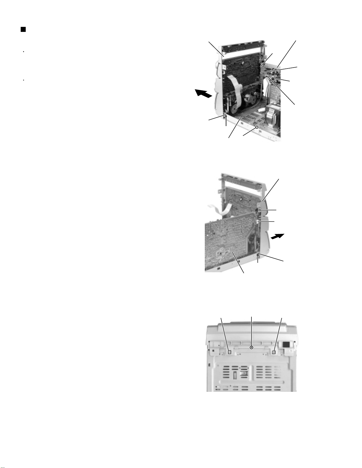
Removing the front panel assembly
(See Fig.11 to 13)
Front panel assembly
Mother (main) board
Prior to performing the following procedure, remove
the top cover, the side covers, the CD Tray fitting
and the CD changer unit.
There is no need to remove the rear panel.
1.
Disconnect the harness from head wire connector
DW1 and DW2 on the inner side of the mother
(main) board in the body.
2.
Disconnect the harness from connector HCW1 of the
headphone board on the right side of the body.
3.
Remove the three screws F attaching the front panel
assembly on both sides of the body.
Remove the screw V attaching the earth terminal
extending from the front compartment.
4.
Remove the screw G attaching the front panel
assembly on the bottom of the body.
5.
Release the two joints d on both sides and two joints
e on the bottom of the body using a screwdriver. At
the same time, disconnect the front compartment
from connector CCW1 and CCW2 of the
mother(main) board.
Joint d
F
earth wire
CCW1
CCW2
DW2
DW1
V
Fig.11
Front panel assembly
F
Headphone board
HCW1
Mother (main) board
Fig.12
Joint e
Fig.13
G
F
Joint d
Joint e
1-8
Page 9
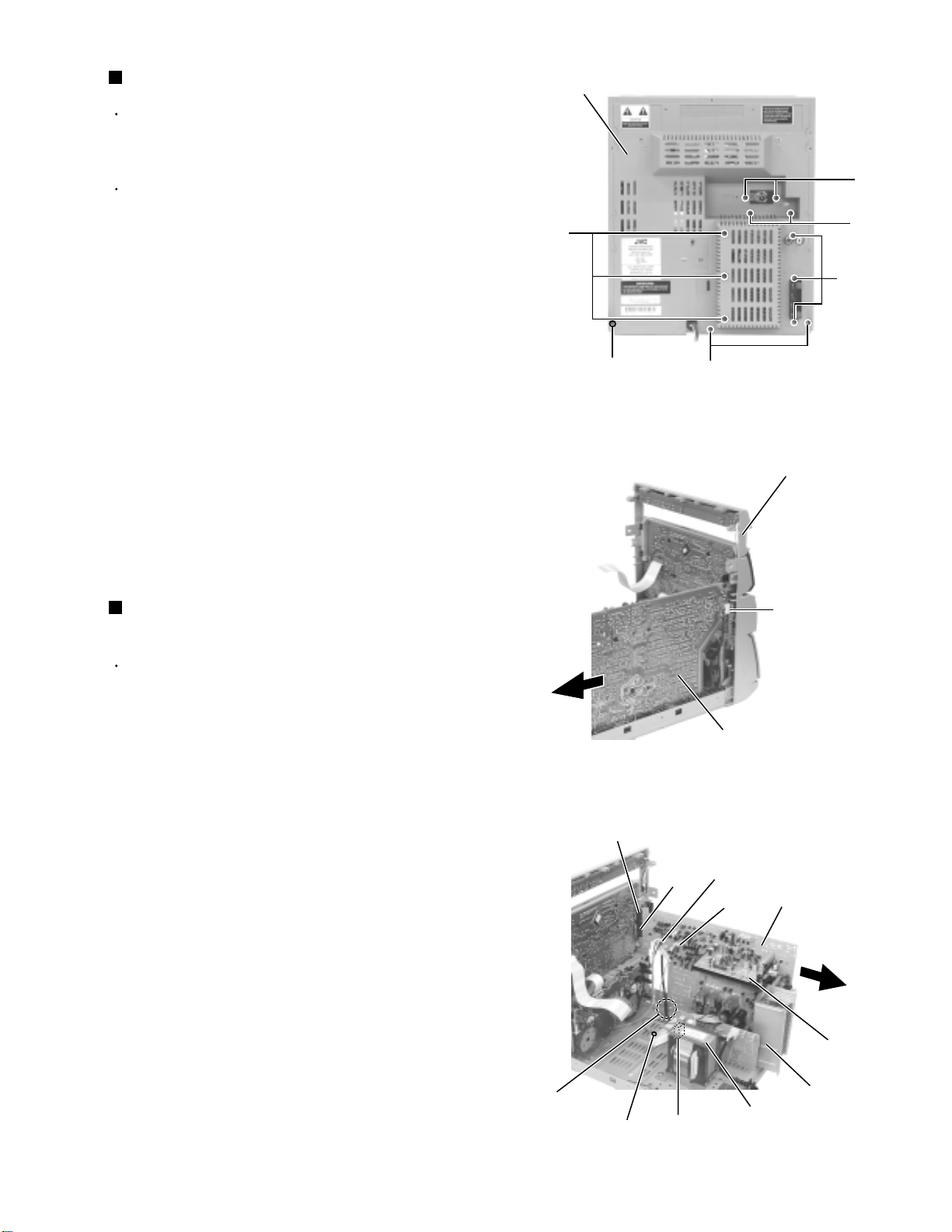
MX-J100
Prior to performing the following procedure, remove
the top cover, the side covers, the CD Tray fitting
and the CD changer unit.
There is no need to remove the front panel
assembly.
Remove the seven screws H attaching the
mother(main) board and the tuner board to the rear
panel on the back of the body.
Remove the three screws I attaching the heat sink
to the rear panel on the back of the body.
Remove the three screws J attaching the rear panel
on the back of the body.
1.
2.
3.
Removing the rear panel (See Fig.14)
Prior to performing the following procedure, remove
the rear panel.
Disconnect the harness from connector HCW1 of the
mother(main) board on the right side of the body.
Release the harness from the clamp in the body.
Disconnect the harness from head wire connector
DW1 and DW2 extending to the mother(main) board
in the body.
Disconnect the harness from connector RCW1 of the
power transformer.
Remove the screw K attaching the earth terminal to
the base chassis.
Disconnect connector CCW1 and CCW2 connected
to the mother(main) board from the front
compartment (The mother(main)) board will be
detached with the tuner board and the assembly.
1.
2.
3.
4.
5.
Removing the mother(main) board
(See Fig.15 and 16)
Fig.14
Fig.15
Fig.16
H
Rrear panel
H
H
J
J
I
Front panel assembly
Mother (main) board
Headphone board
HCW1
Mother (main) board
Heat sink
Tuner board
DW2
DW1
CCW2
CCW1
Power transformer
RCW1
K
Clamp
1-9
Page 10
MX-J100
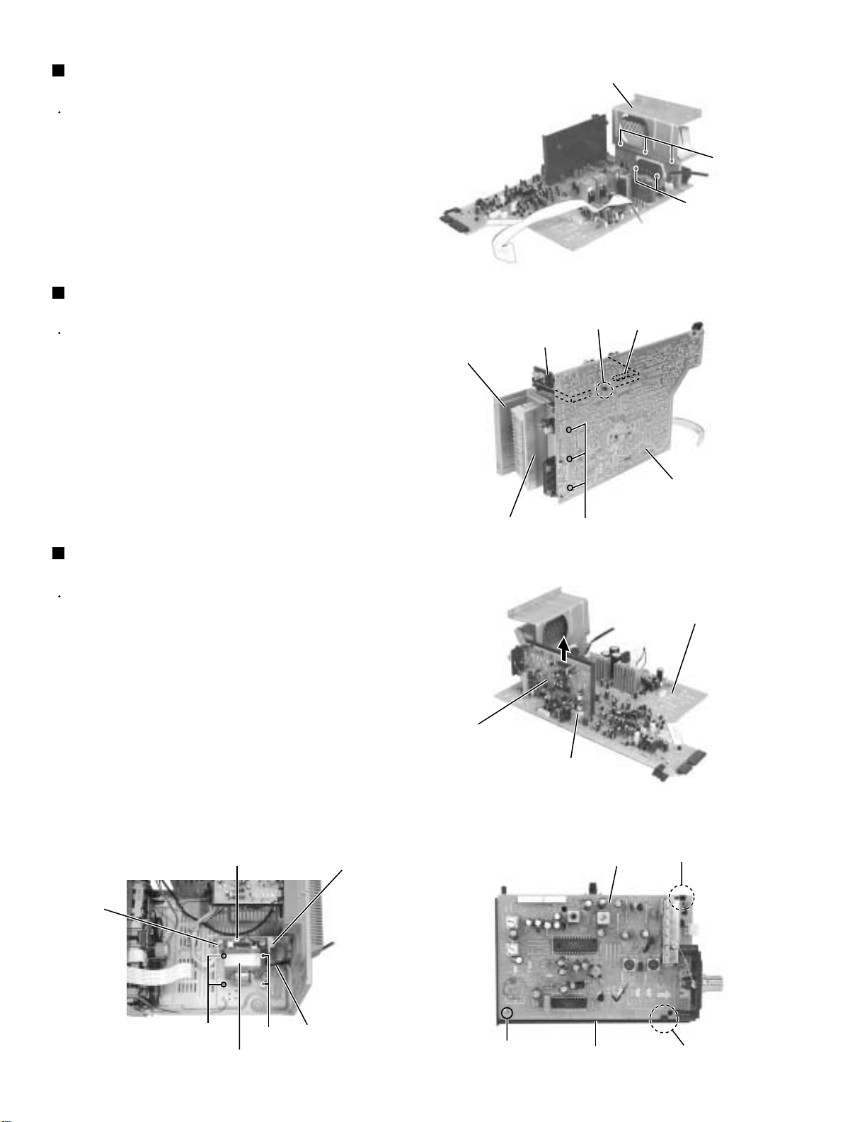
Removing the heat sink
(See Fig.17 and 18)
Prior to performing the following procedure, remove
the mother(main) board.
1.
Remove the three screws L attaching the heat sink
cover plate.
2.
Remove the two screws M attaching the power IC to
the heat sink and the three screws N attaching the
heat sink to the mother (main) board.
Removing the tuner Board
(See Fig. 18 to 20)
The tuner board can be removed even if the
mother(main) board is attached.
1.
Release the joint tab f of the tuner board holder and
the mother(main) board, and disconnect connector
FW1 connected to the mother(main) board. Remove
the tuner board assembly (Refer to Fig.18).
2.
Remove the screw O attaching the tuner board
holder. Release the two tabs g outward and remove
the tuner board from the holder.
Removing the power transformer
(See Fig .21)
Prior to performing the following procedure, remove
the top cover and the side covers.
Heat sink cover plate
Tuner board
Heat sink cover plate
Heat sink
Fig.17
Joint tab f
N
Fig.18
L
M
FW1
Mother(main) board
Mother(main) board
1.
Disconnect the power cord from connector RCW2 of
the power transformer.
2.
Disconnect the harness from connector RCW1 of the
power transformer.
3.
Remove the four screws P attaching the power
transformer and the screw Q attaching the earth
terminal.
ATTENTION:
RCW1
1-10
Prior to disconnecting the power cord
from the body, remove the rear panel.
Q
P
Power transformer
Fig.21
P
RCW2
Power cord
Tuner board
FW1
O
Tuner board holder
Fig.19
Tuner board
Fig.20
Tab g
Tab g
Page 11
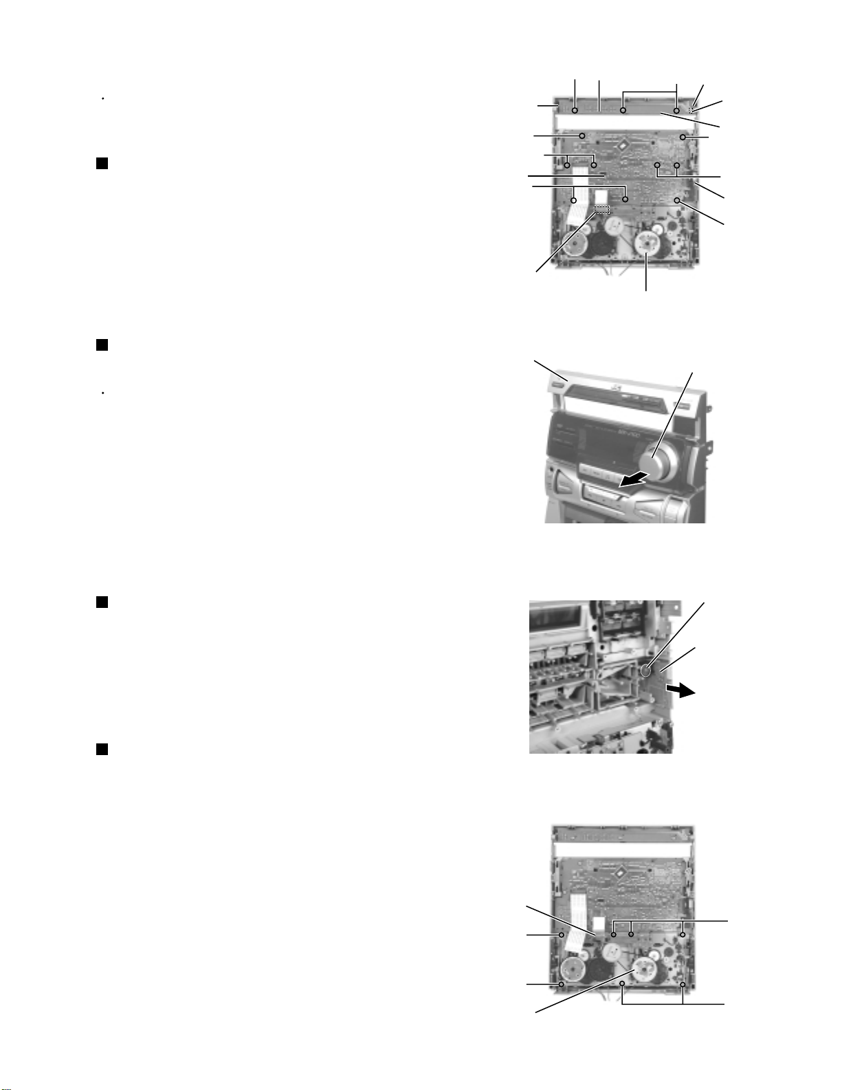
MX-J100
Prior to performing the following procedure, remove
the power / CD switch board.
Pull out the volume knob toward the front.
Disconnect the card wire from the mechanism board
of the cassette mechanism assembly.
Remove the nine screws S attaching the system
board.
1.
2.
3.
Removing the system board
(See Fig.22 and 23)
Remove the three screws R attaching the power /
CD switch board and release the three tabs h
outward.
Disconnect the harness from connector UCW2 of the
power / CD switch board.
1.
2.
Prior to performing the following procedure, remove
the top cover, the side covers, the CD tray fitting and
the front panel assembly.
Removing the power / CD switch board
(See Fig.22)
Disconnect the card wire from the mechanism board
of the cassette mechanism assembly.
Remove the seven screws U attaching the cassette
mechanism assembly.
1.
2.
Removing the cassette mechanism
assembly (See Fig.25)
<Front panel assembly>
Remove the system board temporarily and remove
the screw T attaching the headphone board. Pull out
the headphone board.
1.
Removing the headphone board
(See Fig.24)
Fig.22
Fig.23
Fig.24
Fig.25
Tab h
Power / CD
switch board
R
S
Headphone
board
Tab h
Tab h
Cassette mechanism assembly
UCW2
R
S
S
S
S
S
System board
Mechanism board
Front panel assembly
Volume knob
Headphone board
T
Cassette mechanism assembly
Mechanism board
U
U
U
U
1-11
Page 12
MX-J100
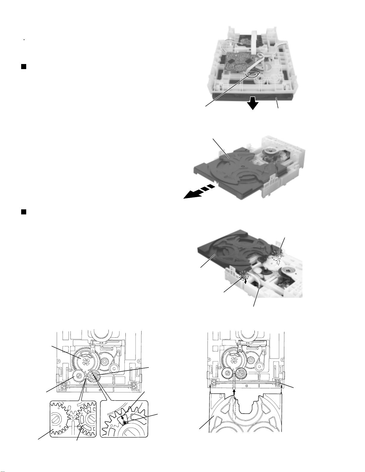
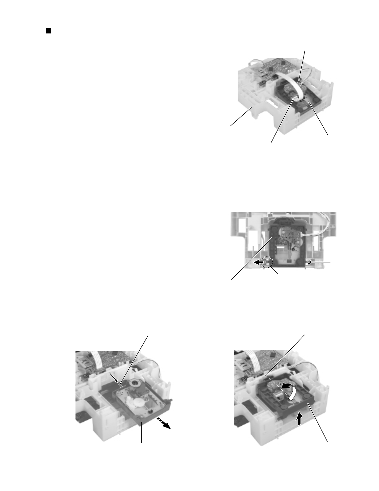
<CD changer unit>
Prior to performing the following procedure, remove
the CD changer unit.
Removing the CD tray (See Fig.26 to 28)
1.
Turn the black loading pulley gear marked c on the
under side of the CD changer unit in the direction of
the arrow and draw the CD tray toward the front until
it stops.
2.
Disconnect the card wire from connector SCW5 of
the CD servo board on the upper side of the CD
changer unit.
3.
Push down the two tray stoppers marked i and pull
out the CD tray.
Loading pulley gear marked c
CD tray
CD tray
Fig.26
Reinstall the CD tray (See Fig.29 to 30)
1.
Align the gear-cam with the gear-tray as shown
fig.29, then mount the CD tray.
2.
When assembling the CD tray, take extreme care not
engage with gear - synchro.
Gear-cam
Gear-tray
Fig.27
Tray stopper marked i
CD tray
Tray stopper marked i
CD servo board
SCW5
Fig.28
Gear-convert
Gear-convert
1-12
Gear-tray
Gear-cam
timing point
Gear-tray
CD tray
Fig.29 Fig.30
Gear-synchro
Page 13
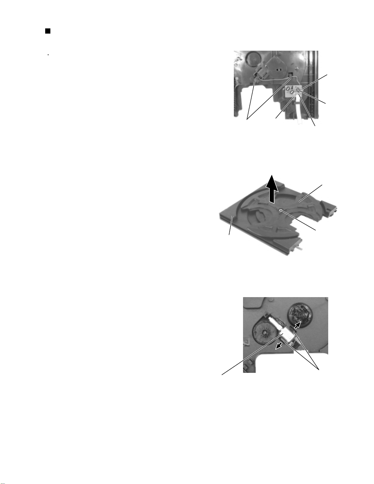
Removing the sensor board / the tray
motor (See Fig.31 to 33)
Prior to performing the following procedure, remove
the CD tray.
1.
Release the two tabs j attaching the sensor board on
the under side of the CD tray.
2.
Disconnect the harness from connector CW1 on the
sensor board and release the harness from the two
hooks k. Remove the sensor board.
3.
Remove the screw W attaching the tray turn table.
Detach the tray turn table from the tray.
4.
Pull outward the tab marked m attaching the tray turn
table motor assembly on the upper side of the tray
and detach the tray turn table motor assembly from
the tray.
Hooks k
MX-J100
Tab j
CW1
Tab j
Sensor board
Fig.31
Tray turn table
Tray
Tray turn table motor assembly
W
Fig.32
Tab m
Fig.33
1-13
Page 14
MX-J100
Removing the belt, the CD servo board
and the switch board (See Fig.34 and 35)
Prior to performing the following procedure, remove
the CD tray.
1.
Detach the belt from the pulley on the upper side of
the CD changer unit (Do not stain the belt with
grease).
2.
Disconnect the card wire from the pickup unit
connector on the under side of the CD changer unit.
3.
Disconnect the motor wire harness from connector
on the CD mechanism board.
4.
Remove the two screws X attaching the CD servo
board. First release the n side of the two tabs n and
two tabs o attaching the CD servo board motor to
raise the CD servo board slightly, then release the o
side.
If the tabs n and o are hard to release, it is
recommendable to unsolder the two soldered parts
on the motor terminal of the CD servo board.
Disconnect the terminal CW3 connected to the
switch board and remove the CD servo board.
Tabs p
CD changer unit
Fig.34
X
CD servo board
Tabs o
Belt
Soldered parts
Motor
Tabs n
5.
Release the three tabs p attaching the switch board
outward and detach the switch board.
Switch board
CW3
Pickup unit connector
Fig.35
CD mechanism board
motor connecter
1-14
Page 15
Removing the CD mechanism holder
assembly (mechanism included)
(See Fig.36 to 39)
1.
Disconnect the harness from connector on the CD
mechanism board in the CD mechanism assembly
on the under side of the CD changer unit. Disconnect
the card wire from the pickup unit connector.
2.
Remove the screw Y attaching the shaft on the right
side of the CD mechanism holder assembly. Pull
outward the stopper fixing the shaft on the left side
and remove the CD mechanism holder assembly
from behind in the direction of the arrow.
3.
Turn the CD mechanism holder assembly half
around the lift up slide shaft r of the CD mechanism
holder assembly until the turn table is reversed, and
pull out the CD mechanism holder assembly.
MX-J100
Motorconnecter
CD changer unit
CD mechanism assembly
Pickup unit connector
Fig.36
Lift up slide shaft
Y
Stopper
CD mechanism holder assembly
Fig.37
Lift up slide shaft r
CD mechanism holder assembly
Fig.39
CD mechanism holder assembly
Fig.38
1-15
Page 16
MX-J100
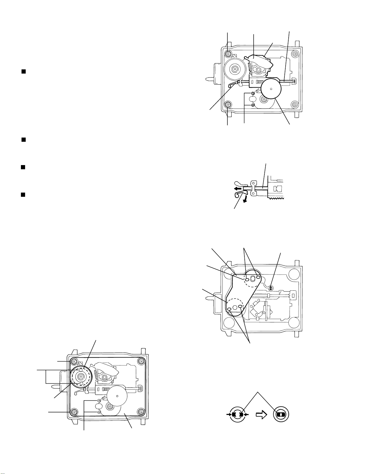
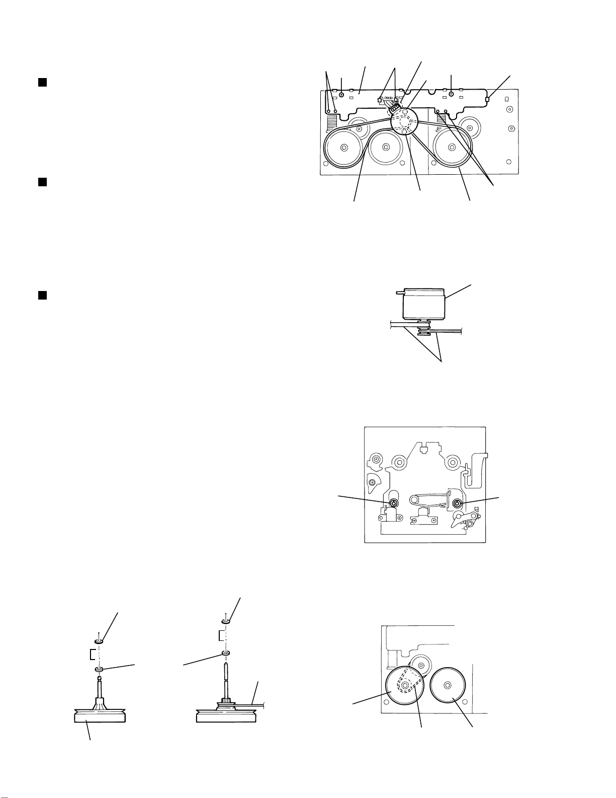
<CD mechanism section>
Removing the CD mechanism holder from the CD
chassis to remove the CD mechanism.
(Refer to "Removing the CD mechanism holder
assembly" (Pag.2-11))
Removing the pickup unit.
1. Loosen the two screws A fixing the chassis.(Fig.1)
2. Removing the feed gear stopper c on the
bottom of the mechanism and pull out the gear.
(Fig.1, Fig.3, Fig.4)
3. Pull out the shaft by opening the pickup shaft
stopper outward to unlock.(Fig.1, Fig.2)
4. Removing the pickup unit.(Fig.1)
Removing the motor board.
1. Unsolder the motor terminal on the motor board.(Fig.3)
2. Remove the moter board.(Fig.3)
Removing the feed motor.
Remove the two motor fixing screws at B and
removing the feed motor.(Fig.1, Fig.3)
Removing the spindle motor.
The spindle motor cannot be removed as a single unit.
When removing the spindle motor, change the chasis
and turntable together as aunit.(Fig.5)
Stopper
A
A
Stopper
Shutter
Pickup unit
B
Fig.1
Fig.2
Shaft
Feed Gear
Shaft
Screw
W
Turn table
Screw
Spindle motor
Motor board
Feed motor
Spindle motor
Unsolder
c
Unsolder
Fig.3
1-16
B
Chassis
(Feed gear stopper)
Fig.4Fig.5
Page 17
MX-J100
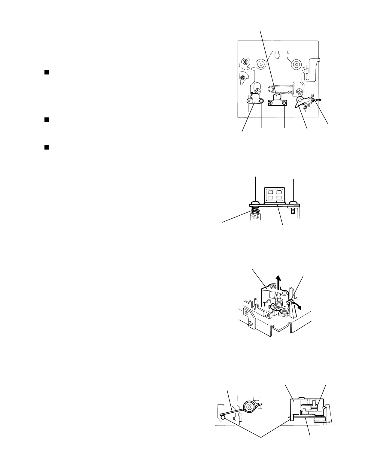
<Cassette mechanism section>
• Removing the record/playback mechanism.
Removing the R/P head.
1. Remove the screw A on the right side of the
R/P head.(Fig.1, Fig.2)
2. Remove the screw B on the left side of the
R/P head.(Fig.1, Fig.2)
Remove the erase head.
Remove the screw C fixing the erase head.(Fig.1)
Removing the pinch roller.
1. Pull out the pinch roller by opening the pinch
roller stopper outward to unlock .(Fig.3)
2. When reassembling the pinch roller, refer to
fig. 4 to hook up the spring.
R/P Head
E. Head
Stoppsr
A
B
C
Fig.1
B
Pinch roller
assembly
A
Spring
Pinch roller
Return spring
R/P Head
Fig.2
Pinch roller
stopper
Fig.3
Pinch roller
Pinch roller
spring
Return spring
Return spring
Fig.4
1-17
Page 18
MX-J100
Removing the motor.
1. Remove the two screws D fixing the motor.
Be careful to grease's splash when the
drive belt comes off.(Fig.5, Fig.6)
2. Unsolder the motor terminal.(Fig.5)
Removing the mechanism board.
1. Unsolder the four parts a on the solenoid
coil terminal.(Fig.5)
2. Remove the two screws E fixing the board.(Fig.5)
3. Unhook the three parts b from the board.(Fig.5)
4. Remove the mechanism board.(Fig.5)
Removing the flywheel.
Remove the cut-washers at c and d from the
capstan shaft, then remove the flywheen.
When reassembling the flywheel,
be sure to use new washers as they
cannot be reused.(Fig.8, Fig.9)
a
E
Drive belt
Mecha.
board
b
Motor
Motor
terminal
D
D
Fig.5
Drive belt
Fig.6
E
Drive belt
Motor
b
a
1-18
Sleeve
Flywheel
c
Washer
Sleeve
d
FR belt
Capstan
washer
Flywheel
Fig.7
FR belt
Fig.8Fig.9
Capstan
washer
Flywheel
Page 19
*
TESTER
MAIN
PCB
VT GND
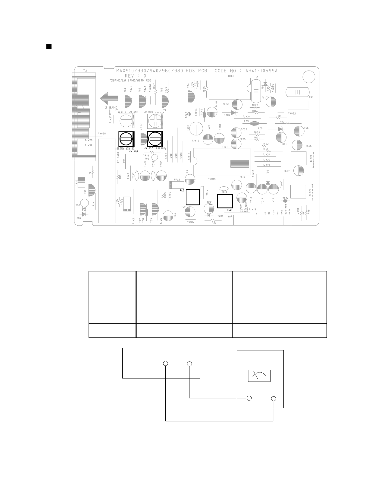
Ajustment method
Tuner
MX-J100
ITEAM
Received FREQ.
Adjustment
point
Output
Adjustment Location of Tuner PCB
AM(MW) OSC Adjustment
520~1720 KHz
Adjustment
Non-
1~7.0±0.5V
590 KHz
AM(MW) RF Adjustment
MW -ANT
Maximum Output(Fig1-4)
Fig 1-4 OSC Voltage
1-19
Page 20
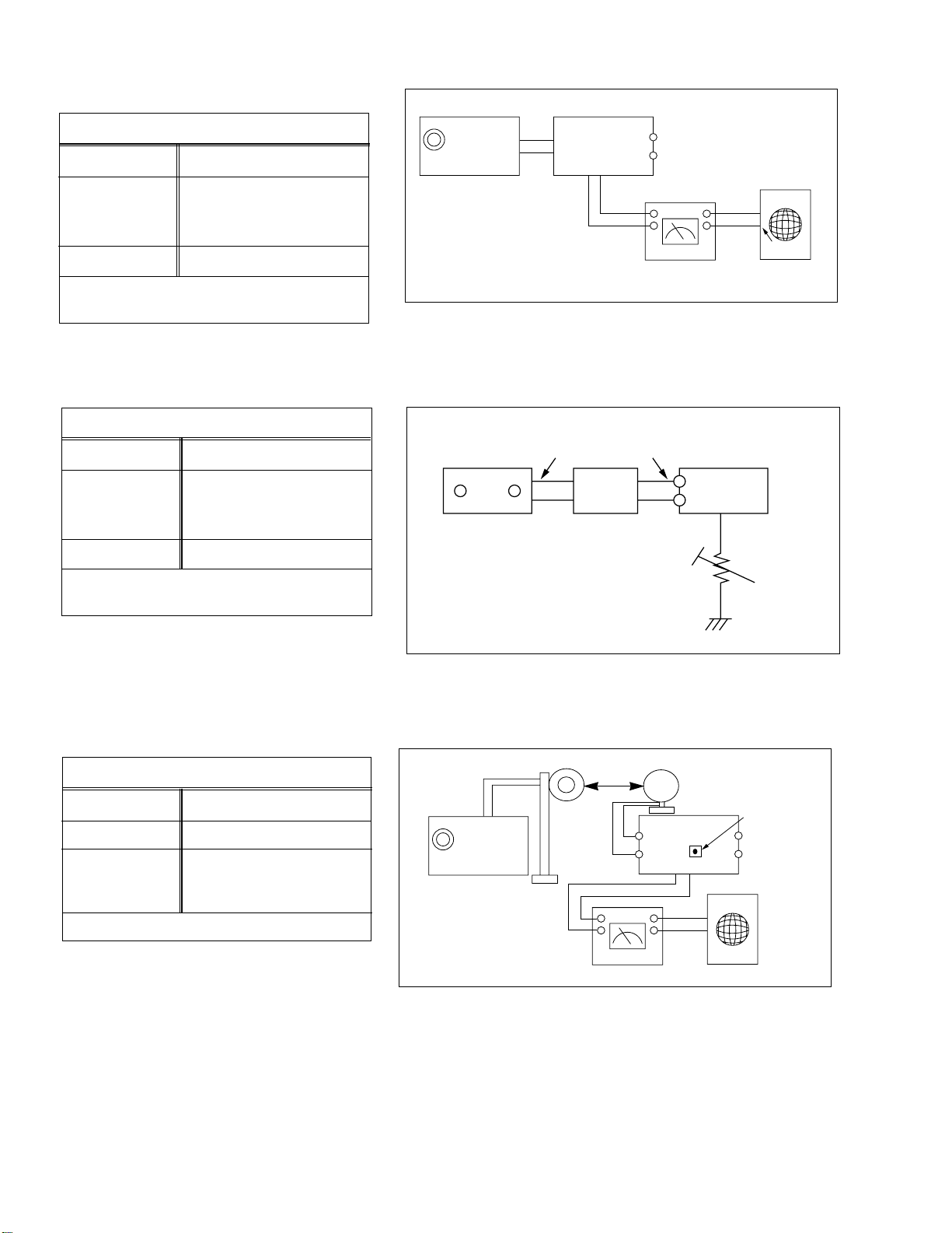
MX-J100
FM THD Adjustment
SSG FREQ.
98 MHz
Adjustment
point
FM DETECTOR COIL
(TL3)
Output
60 dB
Minumum Distortion (0.3% below)
(Figure 1-1)
FM Search Level Adjustment
SSG FREQ.
Adjustment
point
(TSR1)
Output
BEACON
SENSITIVITY
SEMI-VR(20K½)
28 dB(±2dB)
98 MHz
Output
GND
FM S.S.G
FM
Antenna
Terminal
Speaker
Terminal
SET
Input
output
Distortion Meter
Figure1-1 IF CENTER and THD Adjustment
FM Antenna
SET
FM IN
FM S.S.G
28 dB
GND
Oscilloscope
Input
Adjust TSR1 so that “TUNED” of FL T
is lighted (Figure 1-2)
*Adjust FM S.S.G level to 28dB
AM(MW) I.F Adjustment
SSG FREQ.
Frequency
450 kHz
520 kHz
Adjustment
point
AM I.F COIL
(TL2)
Maximum output (Figure 1-3)
Figure1-2 FM Auto Search Level Adjustment
60cm
OUTPUT
AM SSG
450KHZ
INPUT
AM ANT
IN
Speaker Terminal
OUTPUT
VTVM Oscilloscope
Figure1-3 AM I.F Adjustment
20 k½
TL2
1-20
Page 21
(GND)
VTVM
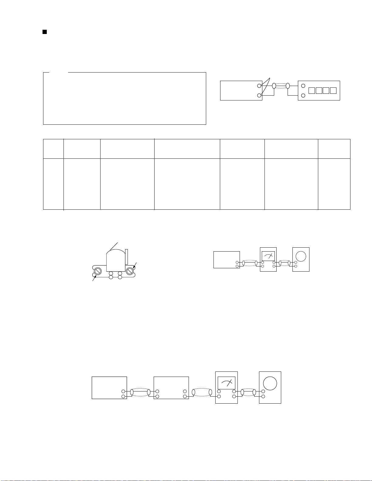
1. To adjust tape speed
1) Measuring tape: VT 712 (or equivalent)
(Tapes recorded with 3kHz)
2) Connect the cassette deck to the frequency counter
as in figure 1-5.
Notes
NOR
SPEED
Control
1
OUT
(connected
to the frequency
counter)
Turn UVR2 to
left and right
(FRONT PCB)
3KHz
Remark
Standard
To Adjust
Pre-Setup
Item
Step
Pre-Setup
Condition
1) Deck A:VT 712
2) Press PLAY
SW button
3) Deck B:Same
as above
Cassette Deck
output
SPK OUT
Frequency Counter
Figure 1-5
Figure 1-6
SPK OUT
Recording /Play head
FWD PLAY
REVERSE PLAY
AZIMUTH control screw
Figure 1-7
In Out
Cassette Deck
Oscilloscope
±1%
range
Figure 1-8
Audio OSC.
SET
(MAIN PCB)
Oscilloscope
AUX IN
LINE OUT
VTVM
IN
DW2
IN OUT
TP
Cassette deck
MX-J100
1-21
Page 22

MX-J100
2. To adjust playback lebel/REC
Notes
1) Before the actual adjustment, clean the play/recording
head.
2) Measuring tape :
i) VT 705(or equivalent 12.5kHz AZIMUTH control)
3) The cassette deck is connections as shown in figure 1-7.
1 Adjust Deck A Play Level
Step
Item
Pre-Setup
Condition
Pre-Setup
To Adjust
Standard
Remark
After putting VT705
TP1 OUT
AZIMUTH
1
Adjust Deck B Play Level/REC BIAS
2
Step
1
2
Item
AZIMUTH
Recording
Bias
Voltage
(VTVM is
connected to
the scope)
Pre-Setup
Condition
TP1 OUT
(VTVM is
connected to
the scope)
Fig 1-8
into Deck A
- Press FWD PLAY
button.
After putting VT705
into Deck B
1)Press FWD PLAY
button.
2)Press REV PLAY
button.
After putting MTT5512 into Deck B
1)Press REC PLAY
button.
2)MAIN PCB DCW2,
connectted to VTVM
Pre-Setup
- Turn the control
screw to as shown
in Figure 1-6.
To Adjust
- Turn the control
screw to as shown
in Figure 1-6.
Turn DVR1,DVR2
to the right and left
Max output
and same phase
(both channels)
Standard
Max output
and same phase
(both channels)
7V(±0.5V)
After
adjustment
secure it with
REGION
LOCK.
Remark
After
adjustment
secure it with
REGION
LOCK.
1-22
Page 23
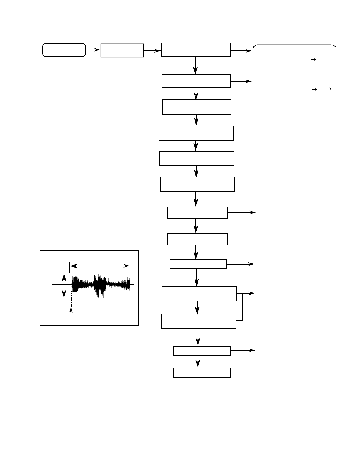
Flow of functional operation until TOC read
Power ON
Play Key
RESET a CD LSI
Confirm that the voltage at the pin38
of KB9223(IC922) is "L" "H".
MX-J100
Check Point
LIMIT SW ON
SET Default value of
TE gain, TE balance
Automatic adjusting of
focus bias
Automatic adjusting of
FE offset
Automatic adjusting of
TE offset
LASER power ON
Detection of disk
Confirm that the voltage at the pin41
of KB9223(IC922) is "H" "L" "H".
Confirm that the voltage at the
pin70 of KB9223(IC922) is 3.5V.
Tracking error waveform at TOC reading
Pin 54 of
KB9223/TE
(IC922)
Approx
0.4V
2.50V
Disc states
to rotate
Approx.3.7sec
Disc is rotated
Automatic adjusting of
TE balance
Automatic adjusting of
TE gain
TOC reading
Play a disc
Confirm that the signal from pin46
of KB9223(IC922) is 3.5V as a
accelerated pulse during
approx.1.96s.
Confirm the waveform of
the Tracking error signal
at the pin 54 of KB9223(IC922).
Confirm the eye-pattern
at the pin74 of KB9223(IC922).
1-23
Page 24

MX-J100
Maintenance of laser pickup
(1) Cleaning the pick up lens
Before you replace the pick up, please try to
clean the lens with a alcohol soaked cotton
swab.
(2) Life of the laser diode
When the life of the laser diode has expired,
the following symptoms will appear.
1. The level of RF output (EFM output:ampli
tude of eye pattern) will below.
Is the level of
RFOUT under
1.1V
0.2Vp-p?
YES
O.K
NO
Replace it.
Replacement of laser pickup
Turn off the power switch and,disconnect the
power cord from the ac outlet.
Replace the pickup with a normal one.(Refer
to "Pickup Removal" on the previous page)
Plug the power cord in,and turn the power on.
At this time,check that the laser emits for
about 3seconds and the objective lens moves
up and down.
Note: Do not observe the laser beam directly.
Play a disc.
Check the eye-pattern at TP1.
Finish.
(3) Semi-fixed resistor on the APC PC board The semi-fixed resistor on the APC printed circuit board which is
attached to the pickup is used to adjust the laser power.Since this adjustment should be performed to match the
characteristics of the whole optical block, do not touch the semi-fixed resistor.
If the laser power is lower than the specified value,the laser diode is almost worn out, and the laser pickup should
be replaced.
If the semi-fixed resistor is adjusted while the pickup is functioning normally,the laser pickup may be damaged
due to excessive current.
1-24
Page 25

Description of major ICs
LC75341 (FIC1):Function
MX-J100
1-25
Page 26

MX-J100
LC72131D (HIC1) : PLL
XIN
XOUT
FMIN
AMIN
CE
DI
CL
DO
VDD
Vss
22
16
15
17
21
1
1/2
3
4
5
6
C2B
1/F
P0WER
ON
RESET
REFERENCE
DIVIDER
SWALLOW COUNTER
1/16, 1/17 4D1ts
12bita PROGRAMMABLE
DIVIDER
DATA SHIFT REGISTER
LATCH
PHASE DETECTOR
CHARGE PUMP
UNLOCK
DETECTOR
UNIVERSAL
COUNTER
18
19
20
12
PD
AIN
ADUT
IFIN
STK402-040 (AIC1)
7 8 9 10
BO1 BO2 BO3 BO4
11
IO1
13
IO2
1-26
Page 27

LA1837 (TIC1) : FM IF/DET AM RF/IF/DET
MX-J100
1-27
Page 28

MX-J100
KS9286B (IC928) : DSP/D-A Converter
S0S1
SBCK
SDAT
EFMI
CNTVOL
DPFIN
DPFOUT
DPDO
SMEF
SMON
SMDP
SMSD
LOCK
XOUT
XIN
MDAT
MCK
MLT
TRCNT
/ISTAT
66
72
73
75
76
70
37
38
36
69
68
26
SUBCODE
SYNC
DETECTOR
EFM
PHASE
DETECTOR
5
3
4
2
9
8
DIGITAL
PLL
DIGITAL
CLV
SERVO
CPU
INTERFACE
MODE
SELECTOR
23BIT
SHIFT
REGISTER
FRAME SYNC
DETECTOR
PROTECTOR
INSERTER
X-TAL
TIMING
GENERATOR
TRACK
COUNTER
DIGITAL
OUTPUT
32
33
SUBCODE
OUTPUT
EFM
DEMODULATOR
ADDRESS
GENERATOR
16K
SRAM
ECC
INTERPOLATOR
DIGITAL
FILTER
& DE-EMPH
D/A
CONVERTER
SUBCODE-Q
REGISTER
30
SQDT
SQCK
29
8BIT DATA BUS
11
LRCHO
12
ADATAO
14
BCKO
77
BCKI
67
ADATAI
80
LRCHI
24
EMPH
17
VREFL1
22
VREFH1
1-28
63
62
61
XTALSEL
TESTO
CDROM
65
TEST1
7
DATX
19
20
RCHOUT
LCHOUT
Page 29

KB9223 (IC922) : ASSP(CD RF)
FEI
59 54 22 30 29 31 38 37 36 35 51 52 58 26 28 27 3
73
RF–
RFO
PD1
PD2
PD
LD
VR
ARF
IRF
ASY
EFM
RFI
DCB
74
65
66
63
67
F
68
E
79
EI
69
70
71
78
76
75
32
33
77
2
4
RF Amp
RF Amp
Focus Error Amp
FE-BIAS Adjustment
Tracking Error Amp
E/F Balance & Gain
Control
APC Amp
Center Voltage Amp.
RF Level AGC
&
Equalizer
EFM
Comparator
Defect Dectection
Circuit
TE1
WDCH
TRCNT
LOCH
ISTAT
RESET
Micom Data
Interface Logic
MICOM TO SERVO CONTROL
AUTO SEQUENCER
ADJUSTMENT-FREE CONTROL
FS1 to
FS4
TM to
TM6
BAL1 to
BAL5
Built-in Post Filter Amp (L&R)
15 16 13 14 19 17 12 11 9 105
MLT
PS1 to
PS4
MDATA
MCK
ATSC
GA1 to
GAS
TZC
FE2
FLB
FGD
FS3
Focus Phase
Compensation
& Offset cancel circuit
Tracking Phase
Compensation Block
& Jump Pulse GEN.
Sled Servo Amplifier
& Sled Kick GEN.
Spindle Servo LPF
(Double Speed)
MIRROR DETECTION
CIRCUIT
FOK DETECTION
CIRCUIT
MX-J100
60
FDFCT
47
FE-
48
FEO
57
TDFCT
49
TE-
50
TEO
53
TE2
55
LPFT
62
TG2
61
TGU
43
SLO
SL–
44
SL+
42
46
SPDLO
45
SPDL-
23
SMDP
24
SMON
25
SMEF
FSET
6
MIRROR
39
MCP
1
FOK
40
DCC1
GC10
GC11
CH10
CH11
MUTEI
RRC
CH20
CH21
GC21
GC20
1-29
Page 30

MX-J100
KA9258D (IC925) : 4-ch Motor driver
28 27 26 25 24 23 22 21 20 19 18 17 16 15
10K
VCC VCC
GND
10K
10K
10K
T • S D
10K
+-
LEVEL SHIFT
REGULATOR
10K
50K
MUTE
LEVEL SHIFT
-+
10K
10K
1 2 3 4 5 6 7 8 9 10 11 12 13 14
GND
KA22291(DIC1) : Cassette amp.
PB
PR IN(2)
NF(2)
23 22 21 8 20 19 18 15
100K
A-IN
B-IN
PBOUT(2)
Vcc
Vcc
REC GND
PB OUT(1)
24
16
17
9
1
RECORD
LREF
PLAYBACK
LREF
100K
N.F
PRE
INPUT
REC.BIAS
PB.BIAS
INPUT
PRE
NF
MODE CONTROL
/BIAS CIRCUIT
A-IN
B-IN
2 3 4 5 7 6 10
PU
NF(1)
PB IN(1) A/BSWPB GND MUTE
R/PSWMUTE
SW
R/P SW
A/B SELECT S/W
MUTE
ALC RECOUT(2)
(IN2)
ALC TIME CONSTANT
IN(1)
OUT(1)
REC
ALC
DET
100K
PRE
PRE
100K
N.F
INPUT
INPUT
N.F
14
REC NF(2)
REC IN(2)
13
12
REC IN(1)
REC IN(1)
11
1-30
Page 31

PARTS LIST
[ MX-J100 ]
* All printed circuit boards and its assemblies are not available as service parts.
MX-J100
MX-J100
- Contents -
Area suffix
J ----------------------------- U.S.A.
C -------------------------- Canada
Exploded view of general assembly and parts list
CD mechanism assembly and parts list
CD changer mechanism assembly and parts list
Cassette mechanism assembly and parts list
Electrical parts list
Packing materials and accessories parts list
3- 2
3- 4
3- 5
3- 7
3- 8
3-19
3-1
Page 32

Exploded view of general assembly and parts list
Block No.
5
4
MX-J100
3
2
1
U only
3-2
HABC DEFG
Page 33

MX-J100
Parts list
Item Parts number Parts name Area
A
1 AH64-00426B WINDOW-CD 1
2 AH64-00414B DOOR-CD 1
3 AH64-00429B WINDOW-DOOR CD 1
4 AH64-00462A BADGE-JVC 1
6 AH63-00107A SHEET-FRONT 1
7 AH64-00430B WINDOW-VFD 1
8 AH61-00271B CAP-VOLUME 1
9 AH64-00422B KNOB-VOLUME 1
10 AH64-00427B CASSETTE-LID A 1
11 AH64-00428B CASSETTE-LID B 1
12 AH64-00412B DOOR-CASSETTE A 1
13 AH64-00413B DOOR-CASSETTE B 1
14 AH61-62004A SPRING-EJECT A 1
15 AH61-62004B SPRING-EJECT B 1
16 AH64-00364B CABINET-FRONT 1
17 AH61-80030A DAMPER-ASSY 2
18 AH59-50001A LATCH-ASSY 2
19 AH64-00421B KNOB-RECORD 1
20 AH64-00423B KNOB-DUBBING 1
21 AH64-00420B KNOB-CD OPEN 1
22 AH64-00415B KNOB-FUNCTION 1
23 AH64-00418B KNOB-PRESET 1
24 AH64-00425B KNOB-POWER 1
25 AH67-00035A LENS-POWER 1
26 AH64-00440B KNOB-PROGRAM 1
27 AH64-00424A KNOB-SLEEP 1
28 AH64-00416A KNOB-DISC 1
29 AH64-00432A CABINET-SIDE R 1
30 AH64-00431A CABINET-SIDE L 1
31 AH64-00443A CABNET-TOP 1
32 AH61-00021A HOLDER-PCB 1
33 AH61-20540A HOLDER-TUNER 1
34 AH64-30416A CABINET-BOTTOM 1
35 AH64-00365B CABINET-REAR 1
36 AH62-00023A HEAT SINK-MAIN 1
37 AH61-00250A BRKT-H/SINK 1
38 AH61-00252A HOLDER-VFD 1
39 AH61-00380A SHAFT-H/PHONE 1
40 AH26-00054A POWER TRANS 1
41 QMPE090-183-JD POWER CORD 1
42 ----------- DECK CASEETTE 1
43 ----------- CD MECHANISM 1
44 QYSBSF4008Z TAPPING SCREW 4
45 QYSDSF3008N TAPPING SCREW 19
46 QYSBSF3008Z TAPPING SCREW 12
47
(General assembiy)
AH39-20002D
STRAIN RELIEF
Q'ty Description
1
Block No. M1MM
3-3
Page 34

MX-J100
)
)
)
CD mechanism assembly and parts list
1
2
6
5
8
3
4
2
Block No.
5
7
9
15
14
16
1
17
18
ABC
Parts list
Item Parts number Parts name Area
A
1 AH30-00007A OPTICAL PICK-UP 1
2 AJ70-00601A SHAFT-PU 1
4 AJ60-00601D SCREW 2
5 6003-000294 SCREW 2 SHAFT
6 AJ60-00608A WASHER 1 PLAIN
7 AJ66-00006A GEAR(C
8 AJ66-00005A GEAR(B
9 AH91-60150C CHASSIS BASE 1
14 3409-001078 LEAF SWITCH 1
15 AJ66-00004A GEAR(A
16 AJ31-00601E MOTOR-FEED 1
17 AJ41-00601S MOTOR-PCB ASSY 1
18 AJ37-00601A CONNECTOR 1
(CD mechanism)
Q'ty Description
FEED MOTOR
1
1
Ass'y
1 FEED
Block No. M2MM
3-4
Page 35

CD changer mechanism assembly and Parts List
Block No.
8
MX-J100
5
7
6
5
2
3
1
4
4
TRAY STOPPER
BASE MAIN
3
13
18
17
16
11
10
12
CD SUB PCB
14
2
19
20
TRAY DISC ASS'Y
15
1
ABC
21
HOOK
CD MAIN PCB
3-5
Page 36

MX-J100
Parts list
Item Parts number Parts name Area
A
1 AH66-80022A SLIDER CAM 1
2 AH66-60034A ROAD BELT 1
3 AH66-20186A PULLEY GEAR 1
4 AH66-20187A ROAD GEAR 1
5 AH66-20188A CAM GEAR 1
6 AH66-20189A TRAY GEAR 1
7 AH66-20190A CONVERT GEAR 1
8 AH66-20191A SYNCRO GEAR 1
10 AH59-10098A WORM-MOTOR ASSY 1
11 AH69-20044A MOTOR CUSHION 1
12 AH66-20193A ROULLETTE GEAR 1
13 AH66-90056A ROULLETTE TRAY 1
14 AH66-90055A DISK TRAY 1
15 AH59-10099A SENSOR PCB ASSY
16 AH59-10100B TABLE CHUCK ASS 1
17 AH59-10101A MOTOR 1 ASS'Y PARTS
18
19
20
21 1
----------AH66-30086A LIFTER LEVER
AH73-10016A RUBBER CUSHION
-----------
SWITCH BOARD
CD MECHANISM
Q'ty Description
1
1
1
1
Block No. M3MM
3-6
Page 37

Cassette mechanism assembly and parts list
3
1
9
MX-J100
Block No.
1
8
7
10
6
2
12
11
5
14
13
11
14
3
4
8
7
6
5
1
12
15
2
ABC
Parts list
Item Parts number Parts name Area
A
1 AH81-00141A R/P HEAD 2 TC881CB
2 AH81-00142A C.MOTOR ASS'Y 1 ADR2400-SHU2L
3 AH81-00143A MAIN BELT 1 1 ADR2400-MAIN76.
4 AH81-00144A MAIN BELT 2 1 ADR2400-MAIN64.
5 AH81-00101A SUB BELT 2 ADR2400-FR34.7
6 AH81-00102A SOLENOIDE 2 ADR2400-1
7 AH81-00282A SPRING 2
8 AH81-00283A PINCH LOLLER 2 ASS'Y PARTS
9 AH81-00284A E-HEAD 1 TC2131F
10 AH81-00285A MOTOR BRACKET 1
11 AH81-00286A LEAF SWITCH 2 ADR2400-MODE
12 AH81-00287A PHOTO SENSOR 2 ADR2400-SENSOR
13 AH81-00288A CONNECTOR 1 ADR2400-16
14 AH81-00289A LEAF SWITCH 6 ADR2400-MXS0022
15 AH81-00290A P.C.BOARD 1
(Cassette mechanism)
Block No. M4MM
Q'ty Description
3-7
Page 38

MX-J100
Electrical parts list
Electrical parts list
Item
A
A-DEC AH39-20002D CONNECTOR
AC 1 2201-000557 C CAPACITOR
AC 2 2401-000419 E CAPACITOR
AC 3 2201-000368 C CAPACITOR
AC 4 2401-001164 E CAPACITOR
AC 5 2201-000659 C CAPACITOR
AC 6 2401-000357 E CAPACITOR
AC 7 2401-000357 E CAPACITOR
AC 8 2202-000817 C CAPACITOR
AC 10 2202-000854 C CAPACITOR
AC 11 2202-000854 C CAPACITOR
AC 13 2202-000817 C CAPACITOR
AC 14 2201-000368 C CAPACITOR
AC 15 2201-000659 C CAPACITOR
AC 16 2401-000419 E CAPACITOR
AC 17 2201-000557 C CAPACITOR
AC 18 2401-001164 E CAPACITOR
AC 20 2301-000375 C CAPACITOR
AC 21 2301-000375 C CAPACITOR
AC 22 2401-001092 E CAPACITOR
AC 23 2401-002180 E CAPACITOR
AC 24 2401-002180 E CAPACITOR
AC 25 2401-001889 E CAPACITOR
AC 26 2401-000871 E CAPACITOR
AC100 2401-001912 E CAPACITOR
AC102 2401-000419 E CAPACITOR
AD 1 1N4148 GE DIODE
AD 2 1N4148 GE DIODE
AD 3 1N4148 GE DIODE
AD 10 1N4148 GE DIODE
AIC 1 STK402-040 IC POWER AMP
A
AJACK 3716-000209 TERMINAL BLOCK
AJW 1 AH39-00157D LEAD-CONNECTOR
AQ 1 KSD471-YTA TRANSISTOR
AQ 2 KSD471-YTA TRANSISTOR
AQ 6 KSR2003TA TRANSISTOR
AQ 7 KSA708-YTA TRANSISTOR
AQ 8 KSA928A TRANSISTOR
AQ 9 KSD471-YTA TRANSISTOR
AQ 10 KSD471-YTA TRANSISTOR
AR 1 2001-000429 C RESISTOR
AR 2 2001-000773 C RESISTOR
AR 3 2001-000273 C RESISTOR
AR 4 2001-000281 C RESISTOR
AR 5 2001-000864 C RESISTOR
AR 6 2001-000924 C RESISTOR
AR 7 2001-000864 C RESISTOR
AR 8 2001-001153 C RESISTOR
AR 9 2003-000390 OM RESISTOR
AR 10 2003-000390 OM RESISTOR
AR 11 2003-000390 OM RESISTOR
AR 12 2003-000390 OM RESISTOR
AR 17 2001-000028 C RESISTOR
AR 18 2001-000890 C RESISTOR
AR 19 2001-000793 C RESISTOR
AR 20 2001-000864 C RESISTOR
AR 23 2001-000273 C RESISTOR
AR 24 2001-000429 C RESISTOR
AR 25 2001-000780 C RESISTOR
AR 26 2001-000290 C RESISTOR
AR 27 2001-000281 C RESISTOR
AR 30 2003-000689 OM RESISTOR
AR 31 2003-000689 OM RESISTOR
Parts number Parts name Area
(Main board)
Block No. 01
Remarks
Item
A
AR 32 2001-000290 C RESISTOR
AR 33 2001-000780 C RESISTOR
AR 34 2001-000429 C RESISTOR
AR 35 2001-000429 C RESISTOR
AR 35 2001-000411 C RESISTOR
AR 36 2001-000440 C RESISTOR
AR 37 2001-000591 C RESISTOR
AR 38 2001-000429 C RESISTOR
AR 39 2001-000429 C RESISTOR
AR100 2001-000449 C RESISTOR
AR200 2001-000290 C RESISTOR
AR201 2001-000290 C RESISTOR
AR204 2001-000734 C RESISTOR
AR205 2001-000734 C RESISTOR
CCW 1 3710-001567 CONNECTOR
CCW 2 3710-001571 CONNECTOR
CON 1 AH39-50001L LEAD-FASTEN
DC 1 2301-000412 C CAPACITOR
DC 2 2301-000379 C CAPACITOR
DC 3 2301-000404 C CAPACITOR
DC 4 2301-000442 C CAPACITOR
DC 5 2201-000368 C CAPACITOR
DC 6 2201-000368 C CAPACITOR
DC 7 2401-001912 E CAPACITOR
DC 9 2301-000390 C CAPACITOR
DC 10 2301-000379 C CAPACITOR
DC 11 2301-000370 C CAPACITOR
DC 12 2301-000370 C CAPACITOR
DC 13 2401-001022 E CAPACITOR
DC 14 2401-001511 E CAPACITOR
DC 15 2401-000240 E CAPACITOR
DC 16 2301-000474 C CAPACITOR
DC 17 2301-000393 C CAPACITOR
DC 18 2301-000375 C CAPACITOR
DC 19 2401-002180 E CAPACITOR
DC 20 2401-001954 E CAPACITOR
DC 21 2401-001022 E CAPACITOR
DC 22 2202-000781 C CAPACITOR
DC 23 2401-001511 E CAPACITOR
DC 24 2401-000795 E CAPACITOR
DC 25 2401-001022 E CAPACITOR
DC 26 2201-000674 C CAPACITOR
DC 27 2301-000400 C CAPACITOR
DC 31 2401-001080 E CAPACITOR
DC 32 2401-001022 E CAPACITOR
DC 33 2401-001912 E CAPACITOR
DC 34 2401-001080 E CAPACITOR
DC 36 2201-000674 C CAPACITOR
DC 37 2301-000407 C CAPACITOR
DC 38 2401-001022 E CAPACITOR
DC 39 2401-001511 E CAPACITOR
DC 40 2202-000781 C CAPACITOR
DC 41 2401-001022 E CAPACITOR
DC 42 2301-000375 C CAPACITOR
DC 43 2202-000781 C CAPACITOR
DC 44 2401-002180 E CAPACITOR
DC 45 2202-000781 C CAPACITOR
DC 47 2301-000400 C CAPACITOR
DC 48 2202-000796 C CAPACITOR
DC 49 2401-000240 E CAPACITOR
DC 50 2401-001511 E CAPACITOR
DC 51 2301-000393 C CAPACITOR
DC 52 2401-001022 E CAPACITOR
Parts number Parts name Area
Remarks
3-8
Page 39

MX-J100
Electrical parts list
Item
A
DC 54 2301-000390 C CAPACITOR
DC 55 2301-000370 C CAPACITOR
DC 56 2301-000370 C CAPACITOR
DC 57 2301-000379 C CAPACITOR
DC 58 2301-000474 C CAPACITOR
DC 59 2401-000438 E CAPACITOR
DC 60 2401-000438 E CAPACITOR
DC 61 2401-001022 E CAPACITOR
DC 62 2401-001912 E CAPACITOR
DC 63 2202-000821 C CAPACITOR
DC 64 2202-000821 C CAPACITOR
DC 70 2401-001895 E CAPACITOR
DC 71 2202-000781 C CAPACITOR
DC 72 2202-000781 C CAPACITOR
DC 73 2301-000407 C CAPACITOR
DC 74 2202-000243 C CAPACITOR
DC 75 2202-000243 C CAPACITOR
DD 1 1N4148 GE DIODE
DD 2 1N4148 GE DIODE
DD 3 1N4148 GE DIODE
DD 4 1N4148 GE DIODE
DIC 1 KA22291 TRANSISTOR PREAMP
DIC 2 KA4558 TRANSISTOR OP AMP
DL 1 AH26-10002Y COIL BIAS-TRAP
DL 2 AH26-10002Y COIL BIAS-TRAP
DL 5 AH27-00018A COIL BAIS-OSC 85K
DQ 1 KSC2331-Y-TA TRANSISTOR
DQ 2 KSA928A TRANSISTOR
DQ 3 KSC945-YTA TRANSISTOR
DQ 4 KSR1003TA TRANSISTOR
DQ 5 KSC1008-YTA TRANSISTOR
DQ 6 KSC1008-YTA TRANSISTOR
DQ 7 KSC1008-YTA TRANSISTOR
DQ 8 KSC1008-YTA TRANSISTOR
DQ 9 KSR2003TA TRANSISTOR
DQ 10 KSR1003TA TRANSISTOR
DQ 11 KSC945-YTA TRANSISTOR
DQ 12 KSC945-YTA TRANSISTOR
DQ 13 KSC945-YTA TRANSISTOR
DQ 14 KSC945-YTA TRANSISTOR
DQ 15 KSR2003TA TRANSISTOR
DQ 16 KSC945-YTA TRANSISTOR
DQ 17 KSC945-YTA TRANSISTOR
DQ 18 KSR2003TA TRANSISTOR
DQ 20 KSR1003TA TRANSISTOR
DR 1 2001-000429 C RESISTOR
DR 2 2001-000440 C RESISTOR
DR 3 2001-000734 C RESISTOR
DR 5 2001-000290 C RESISTOR
DR 6 2001-001095 C RESISTOR
DR 7 2001-000786 C RESISTOR
DR 8 2001-000591 C RESISTOR
DR 9 2001-000290 C RESISTOR
DR 10 2001-000429 C RESISTOR
DR 11 2001-000708 C RESISTOR
DR 12 2001-000924 C RESISTOR
DR 13 2001-000005 C RESISTOR
DR 15 2001-000290 C RESISTOR
DR 16 2001-000290 C RESISTOR
DR 18 2001-000734 C RESISTOR
DR 19 2001-000290 C RESISTOR
DR 20 2001-000924 C RESISTOR
DR 21 2001-000331 C RESISTOR RN 1/8T 180K-J
Parts number Parts name Area
(Main board)
Block No. 01
Remarks
Item
A
DR 22 2001-000864 C RESISTOR
DR 23 2001-000003 C RESISTOR
DR 24 2001-000786 C RESISTOR
DR 25 2001-000890 C RESISTOR
DR 26 2001-000702 C RESISTOR
DR 27 2001-000325 C RESISTOR
DR 28 2001-000290 C RESISTOR
DR 40 2001-000449 C RESISTOR
DR 41 2001-000734 C RESISTOR
DR 42 2001-000591 C RESISTOR
DR 43 2001-000258 C RESISTOR
DR 47 2001-000522 C RESISTOR
DR 48 2001-000591 C RESISTOR
DR 49 2001-000734 C RESISTOR
DR 50 2001-000613 C RESISTOR
DR 58 2001-000325 C RESISTOR
DR 59 2001-000331 C RESISTOR
DR 61 2001-000734 C RESISTOR
DR 62 2001-000786 C RESISTOR
DR 63 2001-000591 C RESISTOR
DR 64 2001-000290 C RESISTOR
DR 65 2001-000429 C RESISTOR
DR 66 2001-000003 C RESISTOR
DR 67 2001-000924 C RESISTOR
DR 68 2001-000290 C RESISTOR
DR 69 2001-000331 C RESISTOR
DR 70 2001-000003 C RESISTOR
DR 71 2001-000397 C RESISTOR RN 1/8T 180K-J
DR 72 2001-000977 C RESISTOR
DR 73 2001-000449 C RESISTOR
DR 74 2001-000786 C RESISTOR
DR 75 2001-000449 C RESISTOR
DR 76 2001-000429 C RESISTOR
DR 77 2001-000522 C RESISTOR
DR 78 2001-000734 C RESISTOR
DR 79 2001-000449 C RESISTOR
DR 80 2001-000449 C RESISTOR
DR 81 2001-000449 C RESISTOR
DR 82 2001-000449 C RESISTOR
DR 83 2001-000449 C RESISTOR
DR 84 2001-000449 C RESISTOR
DR 85 2001-000786 C RESISTOR
DR 86 2001-000734 C RESISTOR
DR 87 2001-000522 C RESISTOR
DR 88 2001-000449 C RESISTOR
DR 89 2001-000008 C RESISTOR
DR 90 2001-000591 C RESISTOR
DR 91 2001-000008 C RESISTOR
DR 92 2001-000591 C RESISTOR
DR 93 2001-000591 C RESISTOR
DR 94 2001-000864 C RESISTOR
DR 95 2001-000449 C RESISTOR
DR 96 2001-000864 C RESISTOR
DR 97 2001-000525 C RESISTOR
DR 98 2001-000449 C RESISTOR
DR 99 2001-000563 C RESISTOR
DR100 2001-000258 C RESISTOR
DR101 2001-000281 C RESISTOR
DR102 2001-000281 C RESISTOR
DVR 1 2103-000248 SEMI F.VR.
DVR 2 2103-000248 SEMI F.VR.
DVR 3 2103-000492 SEMI F.VR.
DW 1 3711-003111 CONNECTOR
Parts number Parts name Area
Remarks
3-9
Page 40

MX-J100
Electrical parts list
Item
A
DW 2 3711-003107 CONNECTOR
DW 3 3711-003107 CONNECTOR
EC 6 2401-000907 E CAPACITOR
FC 1 2301-000375 C CAPACITOR
FC 2 2301-000375 C CAPACITOR
FC 3 2201-000928 C CAPACITOR
FC 4 2401-001912 E CAPACITOR
FC 5 2401-001511 E CAPACITOR
FC 7 2301-000375 C CAPACITOR
FC 8 2201-000928 C CAPACITOR
FC 9 2401-001912 E CAPACITOR
FC 10 2202-000781 C CAPACITOR
FC 11 2301-000375 C CAPACITOR
FC 12 2202-000781 C CAPACITOR
FC 14 2401-001912 E CAPACITOR
FC 15 2401-001912 E CAPACITOR
FC 16 2201-000368 C CAPACITOR
FC 17 2201-000368 C CAPACITOR
FC 18 2401-001954 E CAPACITOR
FC 19 2401-001912 E CAPACITOR
FC 20 2401-001912 E CAPACITOR
FC 21 2301-000379 C CAPACITOR
FC 22 2201-000504 C CAPACITOR
FC 23 2401-001912 E CAPACITOR
FC 24 2401-001912 E CAPACITOR
FC 25 2401-001912 E CAPACITOR
FC 26 2401-001912 E CAPACITOR
FD 1 1N4148 GE DIODE
FIC 1 LC75341 IC VOLUME/TONE CON
FJACK 3722-000377 JACK-RCA 4P/2C
FQ 1 KSR1009TA TRANSISTOR
FQ 2 KSR1009TA TRANSISTOR
FQ 3 KSR2003TA TRANSISTOR
FQ 4 KSD471-YTA TRANSISTOR
FR 1 2001-000613 C RESISTOR
FR 2 2001-000241 C RESISTOR
FR 3 2001-000023 C RESISTOR
FR 4 2001-000281 C RESISTOR
FR 5 2001-000281 C RESISTOR
FR 6 2001-000281 C RESISTOR
FR 7 2001-000613 C RESISTOR
FR 8 2001-000411 C RESISTOR
FR 9 2001-000008 C RESISTOR
FR 11 2001-000397 C RESISTOR
FR 12 2001-000786 C RESISTOR
FR 13 2001-000613 C RESISTOR
FR 14 2001-000786 C RESISTOR
FR 15 2001-000702 C RESISTOR
FR 16 2001-000429 C RESISTOR
FR 17 2001-000429 C RESISTOR
FR 18 2001-000977 C RESISTOR
FR 19 2001-000221 C RESISTOR
FW 1 3711-004109 CONNECTOR
FW 2 3711-002809 CONNECTOR
PC 1 2401-002592 E CAPACITOR
PC 2 2401-002592 E CAPACITOR
PC 3 2201-000783 C CAPACITOR
PC 4 2201-000783 C CAPACITOR
PC 5 2201-000783 C CAPACITOR
PC 6 2201-000783 C CAPACITOR
PC 7 2401-003116 E CAPACITOR
PC 8 2401-001413 E CAPACITOR
PC 9 2401-001954 E CAPACITOR
Parts number Parts name Area
(Main board)
Block No. 01
Remarks
Item
A
PC 10 2401-001954 E CAPACITOR
PC 11 2401-001895 E CAPACITOR
PC 13 2401-001895 E CAPACITOR
PC 14 2401-001954 E CAPACITOR
PC 15 2401-001954 E CAPACITOR
PC 16 2401-001912 E CAPACITOR
PC 17 2401-000475 E CAPACITOR
PC 18 2401-001511 E CAPACITOR
PC 19 2401-000475 E CAPACITOR
PC 20 2401-000230 E CAPACITOR
PC 21 2401-001954 E CAPACITOR
PC 23 2201-000783 C CAPACITOR
PC 24 2201-000783 C CAPACITOR
PC 25 2401-001538 E CAPACITOR
PC 26 2401-001538 E CAPACITOR
PC 27 2301-000449 C CAPACITOR
PC 28 2401-000795 E CAPACITOR
PC 29 2401-001511 E CAPACITOR
PC 30 2201-000565 C CAPACITOR
PC 31 2401-001895 E CAPACITOR
PC 32 2401-001895 E CAPACITOR
PC 33 2202-000797 C CAPACITOR
PCW 1 AH39-00144A LEAD-CONNECTOR 9P
PD 2 1N5392 DIODE
PD 3 1N5392 DIODE
PD 4 1N5392 DIODE
PD 5 1N5392 DIODE
PD 6 1N4002 DIODE
PD 7 1N4002 DIODE
PD 8 1N4002 DIODE
PD 9 1N5392 DIODE
PD 10 1N5392 DIODE
PIC 1 KA7812-ABC IC REGULATOR
PIC 2 KA7805-AB IC REGULATOR +
A
PIC 3 KA7912-AB IC REGULATOR PL 1 2701-000116 INDUCTOR-AXIAL
PL 2 2701-000298 INDUCTOR-AXIAL AX470UH
PQ 1 2SB1566/EF/ TRANSISTOR POWER
A
A
PQ 2 2SB1566/EF/ TRANSISTOR POWER
PQ 3 KSC1009-YTA TRANSISTOR
PQ 4 KSC945-YTA TRANSISTOR
PQ 5 KSA708-YTA TRANSISTOR
PQ 6 KSA928A TRANSISTOR
PQ 9 KSR1003TA TRANSISTOR
PQ 10 KSA708-YTA TRANSISTOR
PQ 11 KTC4369-Y TRANSISTOR POWER
A
A
PR 1 2003-000690 OM RESISTOR
PR 3 2001-000786 C RESISTOR
PR 4 2001-000793 C RESISTOR
A
PR 5 2008-000135 FUSE RESISTOR
A
PR 6 2008-000135 FUSE RESISTOR
A
PR 7 2008-000135 FUSE RESISTOR
PR 8 2001-000890 C RESISTOR
PR 9 2001-000613 C RESISTOR
PR 10 2001-000734 C RESISTOR
PR 11 2003-000701 OM RESISTOR
PR 12 2001-001096 C RESISTOR
PR 13 2001-001153 C RESISTOR
PR 14 2001-000290 C RESISTOR
PR 15 2001-000522 C RESISTOR
PR 16 2001-000786 C RESISTOR
PR 17 2001-000734 C RESISTOR
PR 18 2001-000977 C RESISTOR
Parts number Parts name Area
Remarks
3-10
Page 41

MX-J100
Electrical parts list
Item
A
PR 19 2001-000290 C RESISTOR
PR 20 2003-000690 OM RESISTOR
A
PR 21 2001-000290 C RESISTOR
PR 22 2001-000522 C RESISTOR
PR 23 2001-000780 C RESISTOR
PR 26 2003-000468 OM RESISTOR
PR 27 2001-000027 C RESISTOR
PZD 1 TZP16A ZENER DIODE
PZD 2 TZP16A ZENER DIODE
PZD 3 UZP5.6B ZENER DIODE
PZD 4 UZ5.1BSB ZENER DIODE
PZD 5 UZP10B ZENER DIODE
PZD 6 UZP10B ZENER DIODE
PZD 8 UZP10B ZENER DIODE
R 100 2001-000977 C RESISTOR
A
RC 1 2201-000546 C CAPACITOR
A
RCW 1 3711-001167 CONNECTOR BOX 9P
RCW 2 3711-000190 CONNECTOR
RF 1 3601-001204 FUSE GMC-1.6A
A
A
RR 1 2008-000135 FUSE RESISTOR
RR 2 2008-000135 FUSE RESISTOR
A
RR 3 2008-000137 FUSE RESISTOR
A
A
RR 4 2008-000137 FUSE RESISTOR
RUCL1 3602-000147 FUSE CLIP
TO CH AH39-50001L LEAD-FASTEN
VR 32 2001-000786 C RESISTOR
VR 32 2001-000786 C RESISTOR
VR 35 2001-000786 C RESISTOR
VR 35 2001-000786 C RESISTOR
Parts number Parts name Area
(Main board)
Block No. 01
Remarks
3-11
Page 42

MX-J100
Electrical parts list
Item
A
ANT AH27-00012A OSC COIL
FMPAK AH40-00003A TUNER PACK
HIC 1 LC72131D IC PLL
HR 1 2007-000586 CHIP RESISTOR
OSC AH27-00008A OSC COIL
TC 1 2203-000609 C CAPASITOR
TC 2 2203-001517 C CAPASITOR
TC 3 2203-000260 C CAPASITOR
TC 4 2401-001975 C CAPACITOR
TC 5 2203-000609 C CAPASITOR
TC 6 2203-000979 C CAPASITOR
TC 7 2203-000429 C CAPASITOR
TC 9 2401-001975 C CAPACITOR
TC 10 2203-000979 C CAPASITOR
TC 11 2401-001912 E CAPACITOR
TC 12 2401-000419 E CAPACITOR
TC 13 2203-000979 C CAPASITOR
TC 14 2201-000565 C CAPACITOR
TC 15 2203-000979 C CAPASITOR
TC 16 2401-001954 E CAPACITOR
TC 17 2401-001912 E CAPACITOR
TC 18 2401-001968 C CAPACITOR
TC 19 2401-001912 E CAPACITOR
TC 20 2203-000260 C CAPASITOR
TC 21 2401-000240 E CAPACITOR
TC 23 2401-001954 E CAPACITOR
TC 25 2401-001954 E CAPACITOR
TC 26 2401-000419 E CAPACITOR
TC 27 2401-000419 E CAPACITOR
TC 28 2203-000260 C CAPASITOR
TC 29 2203-000260 C CAPASITOR
TC 30 2401-000419 E CAPACITOR
TC 32 2203-001132 C CAPASITOR
TC 33 2203-000844 C CAPASITOR
TC 34 2401-000907 E CAPACITOR
TC 35 2203-000979 C CAPASITOR
TC 36 2401-001022 E CAPACITOR
TC 38 2401-001164 E CAPACITOR
TC 39 2201-000565 C CAPACITOR
TC 40 2202-000796 C CAPACITOR
TC 41 2203-000239 C CAPASITOR
TC 42 2202-000796 C CAPACITOR
TC 43 2401-001968 C CAPACITOR
TC 44 2203-000260 C CAPASITOR
TC 45 2203-000979 C CAPASITOR
TC 46 2401-000240 E CAPACITOR
TC 47 2401-001895 E CAPACITOR
TC 48 2202-000807 C CAPASITOR
TC 50 2203-001611 C CAPASITOR
TC 51 2203-001611 C CAPASITOR
TC 61 2203-001105 C CAPASITOR
TC 62 2203-001105 C CAPASITOR
TC 63 2203-001551 C CAPASITOR
TC 64 2203-001551 C CAPASITOR
TC100 2201-000389 C CAPACITOR
TD 3 1N4148 GE DIODE
TD 4 1N4148 GE DIODE
TD 5 1N4148 GE DIODE
TD 6 1N4148 GE DIODE
TFL 1 2903-000119 CERAMIC FILTER SFE10.7MJA-10-A
TFL 2 2903-000105 CERAMIC FILTER 10.7MHZ
TFL 4 14529-304-610 CERAMIC FILTER AHCM2-450BL
TIC 1 LA1837 IC
Parts number Parts name Area
(Tuner board)
Block No. 02
Remarks
Item
A
TJ 1 3716-000210 ANT TARMINAL
TJ 2 3711-000814 CONNECTOR
JW100 2007-000029 CHIP RESISTOR
TJW41 2007-000029 CHIP RESISTOR
TJW42 2007-000029 CHIP RESISTOR
TL 2 AH26-10001E IFT
TL 3 AH26-10020A TRANS DET
TLPF1 AH26-00005A IFT
TLPF2 AH26-00005A IFT
TQ 1 KSC945-YTA TRANSISTOR
TQ 2 KSC838-OTA TRANSISTOR
TQ 3 KSC838-OTA TRANSISTOR
TQ 4 KSA708-YTA TRANSISTOR
TR 1 2001-000331 C RESISTOR
TR 2 2007-000300 CHIP RESISTOR
TR 3 2001-000449 C RESISTOR
TR 4 2007-000872 CHIP RESISTOR
TR 5 2001-000281 C RESISTOR
TR 6 2007-000030 CHIP RESISTOR
TR 7 2007-000518 CHIP RESISTOR
TR 8 2007-000822 CHIP RESISTOR
TR 9 2007-000468 CHIP RESISTOR
TR 10 2007-000308 CHIP RESISTOR
TR 11 2007-000572 CHIP RESISTOR
TR 12 2007-000686 CHIP RESISTOR
TR 13 2001-000515 C RESISTOR
TR 15 2007-000586 CHIP RESISTOR
TR 16 2001-000527 C RESISTOR
TR 17 2007-000981 CHIP RESISTOR
TR 18 2001-000449 C RESISTOR
TR 19 2007-000282 CHIP RESISTOR
TR 20 2007-000409 CHIP RESISTOR
TR 21 2007-000300 CHIP RESISTOR
TR 22 2007-000300 CHIP RESISTOR
TR 23 2007-000710 CHIP RESISTOR
TR 24 2007-000290 CHIP RESISTOR
TR 25 2007-001043 CHIP RESISTOR
TR 27 2007-001071 CHIP RESISTOR
TR 28 2007-000457 CHIP RESISTOR
TR 29 2007-000686 CHIP RESISTOR
TR 30 2001-000117 C RESISTOR
TR 32 2001-000429 C RESISTOR
TR 34 2001-000429 C RESISTOR
TR 35 2007-000493 CHIP RESISTOR
TR 36 2007-000493 CHIP RESISTOR
TR 37 2007-000586 CHIP RESISTOR
TR 38 2007-001177 CHIP RESISTOR
TR 39 2001-000290 C RESISTOR
TR 40 2001-000522 C RESISTOR
TR 40 2001-000522 C RESISTOR
TR 41 2001-000522 C RESISTOR
TR 42 2001-000734 C RESISTOR
TR 43 2007-000290 CHIP RESISTOR
TR 44 2001-000118 C RESISTOR
TR 45 2007-000282 CHIP RESISTOR
TR 46 2007-000300 CHIP RESISTOR
TR 47 2007-000282 CHIP RESISTOR
TR 48 2007-000300 CHIP RESISTOR
TR 49 2007-000282 CHIP RESISTOR
TR 50 2007-000300 CHIP RESISTOR
TR 51 2007-000872 CHIP RESISTOR
TR 52 2007-000468 CHIP RESISTOR
TR 53 2007-000300 CHIP RESISTOR
Parts number Parts name Area
Remarks
3-12
Page 43

MX-J100
Electrical parts list
Item
A
TR 54 2007-000300 CHIP RESISTOR
TR 55 2001-000429 C RESISTOR
TR 56 2007-000300 CHIP RESISTOR
TR 57 2001-000290 C RESISTOR
TR 58 2001-000273 C RESISTOR
TR 61 2001-000591 C RESISTOR
TR 62 2001-000591 C RESISTOR
TR100 2001-000527 C RESISTOR
TR101 2007-000033 CHIP RESISTOR
TR102 2007-000033 CHIP RESISTOR
TR103 2007-000033 CHIP RESISTOR
TR104 2007-000033 CHIP RESISTOR
TR105 2007-000029 CHIP RESISTOR
TSR 1 2103-000290 VR-SEMI F.VR
TWA 1 3710-001421 C/SOCKET 14P
TX 1 2801-000734 CRYSTAL UNIT 7.2MHZ
TZD 1 UZ7.5BSC ZENER DIODE 7.5V
TZD 2 UZP5.1B ZENER DIODE 5.1V
VVC 1 KV1260 VARI-CAPA
Parts number Parts name Area
(Tuner board)
Block No. 02
Remarks
3-13
Page 44

MX-J100
Electrical parts list
Item
A
GND 1 AH39-50001L LEAD-FASTEN
REEYE GP1U281R REMOCON SENSOER
SW 1 3404-000165 TACT SWITCH
SW 2 3404-000165 TACT SWITCH
SW 3 3404-000165 TACT SWITCH
SW 4 3404-000165 TACT SWITCH
SW 5 3404-000165 TACT SWITCH
SW 6 3404-000165 TACT SWITCH
SW 7 3404-000165 TACT SWITCH
SW 8 3404-000165 TACT SWITCH
SW 9 3404-000165 TACT SWITCH
SW 10 3404-000165 TACT SWITCH
SW 11 3404-000165 TACT SWITCH
SW 12 3404-000165 TACT SWITCH
SW 13 3404-000165 TACT SWITCH
SW 14 3404-000165 TACT SWITCH
SW 15 3404-000165 TACT SWITCH
SW 16 3404-000165 TACT SWITCH
SW 17 3404-000165 TACT SWITCH
SW 18 3404-000165 TACT SWITCH
SW 19 3404-000165 TACT SWITCH
SW 20 3404-000165 TACT SWITCH
SW 21 3404-000165 TACT SWITCH
SW 22 3404-000165 TACT SWITCH
SW 23 3404-000165 TACT SWITCH
SW 24 3404-000165 TACT SWITCH
SW 25 3404-000165 TACT SWITCH
SW 27 3404-000165 TACT SWITCH
SW 28 3404-000165 TACT SWITCH
SW 29 3404-000165 TACT SWITCH
SW 30 3404-000165 TACT SWITCH
SW 31 3404-000165 TACT SWITCH
SW 32 3404-000165 TACT SWITCH
SW 33 3404-000165 TACT SWITCH
SW 34 3404-000165 TACT SWITCH
UC 1 2401-000475 E CAPACITOR
UC 2 2401-000475 E CAPACITOR
UC 3 2201-000565 C CAPACITOR
UC 4 2201-000565 C CAPACITOR
UC 5 2201-000565 C CAPACITOR
UC 6 2401-000244 E CAPACITOR
UC 7 2201-000825 C CAPACITOR
UC 8 2201-000825 C CAPACITOR
UC 9 2201-000247 C CAPACITOR
UC 10 2201-000247 C CAPACITOR
UC 11 2401-000475 E CAPACITOR
UC 12 2401-000759 E CAPACITOR
UC 13 2401-001952 E CAPACITOR
UC 15 2202-000854 C CAPACITOR
UC 16 2201-000300 C CAPACITOR
UC 17 2202-000797 C CAPACITOR
UC 18 2202-000797 C CAPACITOR
UC 30 2401-001355 E CAPACITOR
UCW 1 3711-004420 CONNECTOR TMC-D10P
UCW 2 3711-004424 CONNECTOR TMC-D20P
UCW 3 3708-000454 CONNECTOR 22P
UCW 7 3711-000906 CONNECTOR
UCW 8 3809-001146 CABLE FLAT
UCW8W3708-000451 CONNECTOR 16P
UCW 9 AH39-00157A LEAD CONNECTOR 3P
UD 20 1N4002 DIODE
UD 21 1N4002 DIODE
UD 22 1N4002 DIODE
UD 23 1N4148 GE DIODE
Parts number Parts name Area
(Front board)
Block No. 03
Remarks
Item
Parts number Parts name Area
UD 24 1N4002 DIODE
UD 25 1N4148 GE DIODE
UD 27 1N4148 GE DIODE
UD 28 1N4148 GE DIODE
UD 29 1N4148 GE DIODE
UD 30 1N4002 DIODE
UIC 2 NJU3711M I C
ULD 1 LTL-1CHESS-UA LED
UQ 1 KSC945-YTA TRANSISTOR
UQ 2 KSC945-YTA TRANSISTOR
UQ 3 KSA928A TRANSISTOR
UQ 4 KSR1003TA TRANSISTOR
UQ 5 KSR1003TA TRANSISTOR
UQ 6 KSA928A TRANSISTOR
UQ 7 KSA928A TRANSISTOR
UQ 8 KSR1003TA TRANSISTOR
UQ 9 KSC945-YTA TRANSISTOR
UQ 10 KSR1003TA TRANSISTOR
UQ 15 KSR1003TA TRANSISTOR
UR 1 2001-000258 C RESISTOR
UR 2 2001-000405 C RESISTOR RN 1/8T 180-J
UR 3 2001-000241 C RESISTOR
UR 4 2001-000429 C RESISTOR
UR 5 2001-000429 C RESISTOR
UR 6 2001-000429 C RESISTOR
UR 7 2001-000734 C RESISTOR
UR 8 2001-000734 C RESISTOR
UR 9 2001-000734 C RESISTOR
UR 10 2001-000734 C RESISTOR
UR 11 2001-000734 C RESISTOR
UR 12 2001-000734 C RESISTOR
UR 13 2001-000734 C RESISTOR
UR 14 2001-000734 C RESISTOR
UR 15 2001-000734 C RESISTOR
UR 16 2001-000734 C RESISTOR
UR 17 2001-000734 C RESISTOR
UR 20 2001-000290 C RESISTOR
UR 21 2001-000290 C RESISTOR
UR 22 2001-000290 C RESISTOR
UR 23 2001-000290 C RESISTOR
UR 24 2001-000281 C RESISTOR
UR 25 2001-000429 C RESISTOR
UR 26 2001-000429 C RESISTOR
UR 27 2001-000429 C RESISTOR
UR 28 2001-000429 C RESISTOR
UR 29 2001-000429 C RESISTOR
UR 30 2001-000429 C RESISTOR
UR 31 2001-000591 C RESISTOR
UR 32 2001-000429 C RESISTOR
UR 33 2001-000429 C RESISTOR
UR 34 2001-000429 C RESISTOR
UR 35 2001-000429 C RESISTOR
UR 36 2001-000429 C RESISTOR
UR 37 2001-000429 C RESISTOR
UR 38 2001-000290 C RESISTOR
UR 39 2001-000290 C RESISTOR
UR 40 2001-000290 C RESISTOR
UR 41 2001-000290 C RESISTOR
UR 42 2001-000281 C RESISTOR
UR 43 2001-000281 C RESISTOR
UR 44 2001-000281 C RESISTOR
UR 45 2001-000281 C RESISTOR
UR 46 2001-000734 C RESISTOR
Remarks
3-14
Page 45

MX-J100
Electrical parts list
Item
A
UR 47 2001-000449 C RESISTOR
UR 48 2001-000591 C RESISTOR
UR 49 2001-000449 C RESISTOR
UR 50 2001-000258 C RESISTOR
UR 51 2001-001178 C RESISTOR
UR 52 2001-000241 C RESISTOR
UR 53 2001-000429 C RESISTOR
UR 54 2001-000734 C RESISTOR
UR 55 2001-000591 C RESISTOR
UR 56 2001-000508 C RESISTOR
UR 57 2001-000793 C RESISTOR
UR 58 2001-000429 C RESISTOR
UR 59 2001-000241 C RESISTOR
UR 60 2001-000258 C RESISTOR
UR 61 2001-000273 C RESISTOR
UR 62 2001-000273 C RESISTOR
UR 63 2001-000273 C RESISTOR
UR 64 2001-000273 C RESISTOR
UR 65 2001-000429 C RESISTOR
UR 66 2001-000429 C RESISTOR
UR 67 2001-000449 C RESISTOR
UR 68 2001-000281 C RESISTOR
UR 69 2001-000281 C RESISTOR
UR 70 2001-000281 C RESISTOR
UR 71 2001-000429 C RESISTOR
UR 72 2001-000522 C RESISTOR
UR 73 2001-000429 C RESISTOR
UR 74 2001-000429 C RESISTOR
UR 75 2001-000429 C RESISTOR
UR 76 2001-000429 C RESISTOR
UR 77 2001-000429 C RESISTOR
UR 78 2001-000429 C RESISTOR
UR 79 2001-000429 C RESISTOR
UR 80 2001-000290 C RESISTOR
UR 81 2001-000290 C RESISTOR
UR 82 2001-000429 C RESISTOR
UR 83 2001-000273 C RESISTOR
UR 84 2001-000977 C RESISTOR
UR 85 2001-000411 C RESISTOR
UR 86 2001-000786 C RESISTOR
UR 87 2001-000290 C RESISTOR
UR 88 2001-000613 C RESISTOR
UR 89 2001-000613 C RESISTOR
UR 90 2001-000613 C RESISTOR
UR 91 2001-001178 C RESISTOR
UR 92 2001-001178 C RESISTOR
UR 93 2001-000449 C RESISTOR
UR 94 2001-000591 C RESISTOR
UR 95 2001-000290 C RESISTOR
UR 95 2001-000734 C RESISTOR
UR 96 2001-000977 C RESISTOR
UR 97 2001-000411 C RESISTOR
UR 99 2001-000522 C RESISTOR
UR201 2001-000273 C RESISTOR
UVR 1 3406-001047 ROTARY SWITCH
UVR 2 2103-000492 SEMI F.VR.
UX 1 2802-000181 CERAMIC RESONAT 6MHZ
UX 2 2801-001394 CRYSTAL-UNIT 32.768KHZ
UXR 1 2001-000850 C RESISTOR
UXR 2 2001-000295 C RESISTOR
VFDHL AH61-00252A HOLDER-VFD
VFD AH07-00016A FL DISPLAY TUBE
Parts number Parts name Area
(Front board)
Block No. 03
Remarks
3-15
Page 46

MX-J100
Q
Electrical parts list
Item
A
NC 1 2203-000260 C CAPASITOR
NC 54 2401-001952 E CAPACITOR
CW101 AH39-20025S CONNECTOR
CW102
CW500
NC100 2203-000892 C CAPACITOR
NC101 2203-000802 C CAPACITOR
NC102 2203-001551 C CAPASITOR
NC103 2203-000260 C CAPASITOR
NC104 2203-001537 C CAPACITOR
NC105 2401-000240 E CAPACITOR
NC106 2203-000892 C CAPACITOR
NC106 2202-000817 C CAPACITOR
NC107 2203-000206 C CAPACITOR
NC108 2203-000206 C CAPACITOR
NC110 2203-000495 C CAPACITOR
NC111 2203-000802 C CAPACITOR
NC112 2203-000260 C CAPASITOR
NC113 2203-000260 C CAPASITOR
NC114 2401-000419 E CAPACITOR
NC115 2203-001137 C CAPACITOR
NC116 2203-000260 C CAPASITOR
NC117 2203-000477 C CAPACITOR
NC118 2203-000787 C CAPACITOR
NC119 2203-000206 C CAPACITOR
NC120 2203-000206 C CAPACITOR
NC121 2203-000206 C CAPACITOR
NC122 2401-001952 E CAPACITOR
NC124 2401-001324 E CAPACITOR
NC125 2203-000802 C CAPACITOR
NC190 2203-000429 C CAPASITOR
NC200 2203-000979 C CAPASITOR
NC201 2203-001551 C CAPASITOR
NC202 2203-001619 C CAPACITOR
NC203 2203-001619 C CAPACITOR
NC204 2401-001324 E CAPACITOR
NC205 2203-000260 C CAPASITOR
NC300 2202-000796 C CAPACITOR
NC301 2401-000778 E CAPACITOR
NC400 2202-000243 C CAPACITOR
NC50L 2401-001952 E CAPACITOR
NC50R 2401-001952 E CAPACITOR
NC501 2401-000240 E CAPACITOR
NC502 2203-000260 C CAPASITOR
NC503 2203-000260 C CAPASITOR
NC504 2203-000260 C CAPASITOR
NC52L 2203-001537 C CAPACITOR
NC52R 2203-001537 C CAPACITOR
NC53L 2203-000260 C CAPASITOR
NC53R 2203-000260 C CAPASITOR
NC55L 2401-001952 E CAPACITOR
NC55R 2401-001952 E CAPACITOR
NC600 2203-000206 C CAPACITOR
NC601 2401-001895 E CAPACITOR
NC602 2203-000260 C CAPASITOR
NC603 2203-001537 C CAPACITOR
NC604 2203-000979 C CAPASITOR
NC700 2401-000778 E CAPACITOR
NC701 2401-000778 E CAPACITOR
NC702 2401-000240 E CAPACITOR
NC703 2401-001102 E CAPACITOR
NC800 2203-000260 C CAPASITOR
NC804 2203-000260 C CAPASITOR
Parts number Parts name Area
AH39-20561P
3711-000906
(CD board)
CONNECTOR
CONNECTOR
Block No. 04
Remarks
Item
A
NC901 2203-000206 C CAPACITOR
NC903 2203-001537 C CAPACITOR
NC904 2401-000240 E CAPACITOR
NC905 2203-000260 C CAPASITOR
ND200 1N4148 GE DIODE
ND201 1N4148 GE DIODE
ND202 1N4148 GE DIODE
ND203 1N4148 GE DIODE
NIC05 KA78L05Z-TA IC POSI.ADJUST REG
IC925 KA9258D IC MOTOR DRIVER
IC922 KB9223 IC ASP
IC928 KS9286B IC DSP
NL100 2701-000114 INDUCTOR-AXIAL 10UH
NL101 2701-000111 INDUCTOR-AXIAL 100UH
NL102 2701-000111 INDUCTOR-AXIAL 100UH
NL105 3301-000325 CORE-FERRITE BE
NL300 3301-000297 CORE-FERRITE
NL301 3301-000297 CORE-FERRITE
NL302 3301-000297 CORE-FERRITE
Q1501 KSA928A
NR 1 2001-000429 C RESISTOR
NR 2 2001-000429 C RESISTOR
NR 3 2001-000429 C RESISTOR
NR 4 2007-000468 CHIP RESISTOR
NR 5 2007-000468 CHIP RESISTOR
NR 6 2007-000468 CHIP RESISTOR
NR 7 2007-000468 CHIP RESISTOR
NR 8 2001-000429 C RESISTOR
NR 10 2007-000468 CHIP RESISTOR
NR 11 2007-000468 CHIP RESISTOR
NR 12 2007-000468 CHIP RESISTOR
NR 13 2007-000395 CHIP RESISTOR
NR100 2007-000355 CHIP RESISTOR
NR101 2007-000593 CHIP RESISTOR
NR103 2007-000395 CHIP RESISTOR
NR104 2007-000338 CHIP RESISTOR
NR105 2007-000830 CHIP RESISTOR
NR106 2001-000319 C RESISTOR
NR107 2007-000338 CHIP RESISTOR
NR108 2007-000941 CHIP RESISTOR
NR109 2007-000282 CHIP RESISTOR
NR111 2007-000941 CHIP RESISTOR
NR112 2007-001039 CHIP RESISTOR
NR113 2001-000977 C RESISTOR
NR114 2007-000477 CHIP RESISTOR
NR115 2007-000444 CHIP RESISTOR
NR116 2007-001195 CHIP RESISTOR
NR117 2007-000898 CHIP RESISTOR
NR119 2007-000395 CHIP RESISTOR
NR120 2007-000355 CHIP RESISTOR
NR121 2007-000355 CHIP RESISTOR
NR200 2007-000653 CHIP RESISTOR
NR201 2007-000686 CHIP RESISTOR
NR202 2007-000686 CHIP RESISTOR
NR203 2007-000282 CHIP RESISTOR
NR204 2007-000355 CHIP RESISTOR
NR300 2007-000282 CHIP RESISTOR
NR400 2007-000409 CHIP RESISTOR
NR50L 2007-000586 CHIP RESISTOR
NR50R 2007-000586 CHIP RESISTOR
NR52L 2007-000653 CHIP RESISTOR
NR52R 2007-000653 CHIP RESISTOR
Parts number Parts name Area
1502 KSA812
TRANSISTOR
TRANSISTOR
Remarks
3-16
Page 47

MX-J100
Electrical parts list
Item
A
NR53L 2007-000872 CHIP RESISTOR
NR53R 2007-000872 CHIP RESISTOR
NR54L 2007-000468 CHIP RESISTOR
NR54R 2007-000468 CHIP RESISTOR
NR55L 2007-000872 CHIP RESISTOR
NR55R 2007-000872 CHIP RESISTOR
NR555 2008-000140 C RESISTOR
NR57L 2007-000282 CHIP RESISTOR
NR57R 2007-000282 CHIP RESISTOR
NR602 2007-000300 CHIP RESISTOR
NR603 2007-000300 CHIP RESISTOR
NR604 2007-000468 CHIP RESISTOR
NR606 2007-000282 CHIP RESISTOR
NR804 2007-000468 CHIP RESISTOR
NR994 2007-001208 CHIP RESISTOR
NR995 2007-000830 CHIP RESISTOR
NR996 2007-000830 CHIP RESISTOR
NR997 2007-000830 CHIP RESISTOR
NR998 2007-000830 CHIP RESISTOR
NR999 2007-001208 CHIP RESISTOR
XF100 2802-000211 CERAMIC RESONAT 16.93MHZ
SC 1 2203-000260 C CAPASITOR
SC 2 2203-000260 C CAPASITOR
SC 5 2401-000795 E CAPACITOR
SC 6 2203-000260 C CAPASITOR
SC 14 2401-000240 E CAPACITOR
SCO 4 KA78L05Z-TA IC POSI.ADJUST REG
SCW 1 3708-001438 CONNECTOR 22P
SCW 5 3708-001131 CONNECTOR 5P
SCW 7 3711-003379 CONNECTOR
SIC 1 KA3082 IC MOTOR DRIVER
SIC 2 KA3082 IC MOTOR DRIVER
SL 1 2701-000179 INDUCTOR-AXIAL 33UH
SR 1 2001-000027 C RESISTOR
SR 2 2007-000872 CHIP RESISTOR
SR 3 2007-000468 CHIP RESISTOR
SR 4 2007-000468 CHIP RESISTOR
SZD 1 UZ4.7BM ZENER DIODE 4.7V
SZD 2 UZ6.2BSB ZENER DIODE 6.2V
WCW 1 3708-001252 CONNECTOR 16P
Parts number Parts name Area
(CD board)
Block No. 04
Remarks
3-17
Page 48

MX-J100
Electrical parts list
Item
A
HC 1 2202-000796 C CAPACITOR
HC 2 2202-000796 C CAPACITOR
HC 3 2202-000263 C CAPACITOR
HC 4 2202-000263 C CAPACITOR
HCW 1 3711-001009 CONNECTOR
JACK 1 3722-000363 JACK PHONE
HL 1 2701-000111 INDUCTOR-AXIAL
HL 2 2701-000111 INDUCTOR-AXIAL
HR 1 2001-001178 C RESISTOR
HR 2 2001-001178 C RESISTOR
Parts number Parts name Area
(Mic / Headphone board)
Block No. 05
Remarks
3-18
Page 49

Packing materials and accessories parts list
Block No.M5MM
Block No.M6MM
A1
P
O
W
E
R
P
R
O
G
/
S
R
E
A
T
M
T
I
O
M
R
N
E
E
/
R
C
P
O
E
D
F
A
F
T
S
L
T
E
A
A
E
C
B
P
C
T
A
P
E
I
S
D
V
A
S
E
/
B
E
X
T
.
S
UN
O
T
M
I
U
NG M
A
O
N
P
D
D
E
E
ODE
FM MODE
F
M
/
A
M
A
U
V
X
O
D
L
I
.
S
+
C
S
K
I
F
P
M
A
D
U
E
T
I
N
G
V
O
L
.
–
R
R
E
M
M
–
O
S
T
M
E
X
J
C
1
O
0
N
0
J
T
R
O
A2 A8
L
A9
A9
MX-J100
Packing
Item Parts number Parts name Area
A
Parts list
Q'ty Description
Block No. M5MM
P 1 AH69-00180A CARTON 1
P 2 AH69-00152A CUSHION-L 1
P 3 AH69-00153A CUSHION-R 1
P 4 AH69-30012T POLY BAG 1 SET
P 5 QPA02503503P POLY BAG 1 INSTRUCTIONS
P 6 AH81-00243M CUSHION-BOTTOM 1
P 7 AH81-00243L CUSHION-TOP 1
SPEAKER
SPEAKER
P 8 AH81-00243P POLY BAG 2 SPEAKER
P 9 AH69-00185A PAD-ROLE A 1
P 10 AH69-00185B PAD-ROLE B 1
Accessories
Item Parts number Parts name Area
A
Parts list
Block No. M6MM
Q'ty Description
A 1 AH59-00044A REMOTE-CONTROL 1 22KEY
A 2 AH68-00337A INSTRUCTIONS 1 ENG SPA FRE
A 3 BT-20044G SAFETY SHEET 1
A 4 BT-52004-1 WARRANTY CARD C1
BT51018-2 WARRANTY CARD J1
A 5 BT-20071B SERVICE NETWORK C1
A 6 EWP503-001 ANTENNA WIRE 1 FM
A 7 QAL0014-001 LOOP ANTENNA 1 AM
A 8 ----------- BATTERY 2
A 9 MXJ100J-SPBOX SPEAKER BOX 2
3-19
Page 50

Warnings, Cautions and Others
Mises en garde, précautions et indications diverses
CAUTION
CAUTION
RISK OF ELECTRIC SHOCK
DO NOT OPEN
To reduce the risk of electrical shocks, fire, etc.:
1. Do not remove screws, covers or cabinet.
2. Do not expose this appliance to rain or moisture.
CAUTION: TO REDUCE THE RISK OF ELECTRIC SHOCK,
DO NOT REMOVE COVER (OR BACK).
NO USER SERVICEABLE PARTS INSIDE.
REFER SERVICING TO QUALIFIED SERVICE PERSONNEL.
The lightning flash with arrowhead symbol,
within an equilateral triangle is intended to
alert the user to the presence of uninsulated
"dangerous voltage" within the product's
enclosure that may be of sufficient
magnitude to constitute a risk of electric
shock to persons.
The exclamation point within an equilateral
triangle is intended to alert the user to the
presence of important operating and
maintenance (servicing) instructions in the
literature accompanying the appliance.
For U.S.A.
This equipment has been tested and found to comply with the limits
for a Class B digital device, pursuant to part 15 of the FCC Rules.
These limits are designed to provide reasonable protection against
harmful interference in a residential installation.
This equipment generates, uses and can radiate radio frequency
energy and, if not installed and used in accordance with the
instructions, may cause harmful interference to radio
communications. However, there is no guarantee that interference
will not occur in a particular installation. If this equipment does cause
harmful interference to radio or television reception, which can be
determined by turning the equipment off and on, the user is
encouraged to try to correct the interference by one or more of the
following measures:
Reorient or relocate the receiving antenna.
Increase the separation between the equipment and receiver.
Connect the equipment into an outlet on a circuit different from that
to which the receiver is connected.
Consult the dealer or an experienced radio/TV technician for help.
ATTENTION
Afin d’éviter tout risque d’électrocution, d’incendie, etc.:
1. Ne pas enlever les vis ni les panneaux et ne pas
ouvrir le coffret de l’appareil.
2. Ne pas exposer l’appareil à la pluie ni à l’humidité.
Caution –– POWER switch!
Disconnect the mains plug to shut the power off completely.
The POWER switch in any position does not disconnect the
mains line. The power can be remote controlled.
Attention –– Commutateur POWER!
Déconnecter la fiche de secteur pour couper complètement
le courant. Le commutateur POWER ne coupe jamais
complètement la ligne de secteur, quelle que soit sa position.
Le courant peut être télécommandé.
1. CLASS 1 LASER PRODUCT
2. DANGER: Invisible laser radiation when open and
interlock failed or defeated. Avoid direct exposure to
beam.
3. CAUTION: Do not open the top cover. There are no user
serviceable parts inside the Unit; leave all servicing to
qualified service personnel.
1. PRODUIT LASER CLASSE 1
2. ATTENTION: Radiation laser invisible quand l'appareil
est ouvert ou que le verrouillage est en panne ou
désactivé. Eviter une exposition directe au rayon.
3. ATTENTION: Ne pas ouvrir le couvercle du dessus. Il n'y
a aucune pièce utilisable à l'intérieur. Laisser à un
personnel qualifié le soin de réparer votre appareil.
WARNING: TO REDUCE THE RISK OF FIRE
OR ELECTRIC SHOCK, DO NOT EXPOSE
THIS APPLIANCE TO RAIN OR MOISTURE.
– G-1 –
Page 51

For Canada/pour le Canada
CAUTION: TO PREVENT ELECTRIC SHOCK, MATCH WIDE
BLADE OF PLUG TO WIDE SLOT, FULLY INSERT.
ATTENTION: POUR EVITER LES CHOCS ELECTRIQUES,
INTRODUIRE LA LAME LA PLUS LARGE DE LA FICHE DANS
LA BORNE CORRESPONDANTE DE LA PRISE ET POUSSER
JUSQUAU FOND.
For Canada/pour le Canada
THIS DIGIT AL APPARATUS DOES NO T EXCEED THE CLASS
B LIMITS FOR RADIO NOISE EMISSIONS FROM DIGITAL
APP ARATUS AS SET OUT IN THE INTERFERENCE-CAUSING
EQUIPMENT STANDARD ENTITLED “DIGITAL APPARATUS,”
ICES-003 OF THE DEPARTMENT OF COMMUNICATIONS.
CET APPAREIL NUMERIQUE RESPECTE LES LIMITES DE
BRUITS RADIOELECTRIQUES APPLICABLES AUX
APP AREILS NUMIRIQUES DE CLASSE B PRESCRITES D ANS
LA NORME SUR LE MATERIEL BROUILLEUR: “APPAREILS
NUMERIQUES”, NMB-003 EDICTEE PAR LE MINISTRE DES
COMMUNICATIONS.
– G-2 –
Page 52

Introduction
We would like to thank you for purchasing one of our JVC products.
Before operating this unit, read this manual carefully and thoroughly to
obtain the best possible performance from your unit, and retain this manual
for future reference.
About This Manual
This manual is organized as follows:
• The manual mainly explains operations using the
buttons and controls on the unit. You can also use the
buttons on the remote control if they have the same or
similar names (or marks) as those on the unit.
If operation using the remote control is different from
that using the unit, it is then explained.
• Basic and common information that is the same for many
functions is grouped in one place, and is not repeated in
each procedure. For instance, we do not repeat the
information about turning on/off the unit, setting the
volume, changing the sound effects, and others, which are
explained in the section “Common Operations” on pages 9
and 10.
• The following marks are used in this manual:
Gives you warnings and cautions to prevent
from a damage or risk of fire/electric shock.
Also gives you information which is not good
for obtaining the best possible performance
from the unit.
Gives you information and hints you had better
know.
Power sources
• When unplugging from the wall outlet, always pull the
plug, not the AC power cord.
DO NOT handle the AC power cord with wet
hands.
Moisture condensation
Moisture may condense on the lens inside the unit in the
following cases:
• After starting heating in the room
• In a damp room
• If the unit is brought directly from a cold to a warm place
Should this occur, the unit may malfunction. In this case,
leave the unit turned on for a few hours until the moisture
evaporates, unplug the AC power cord, and then plug it in
again.
Others
• Should any metallic object or liquid fall into the unit,
unplug the unit and consult your dealer before operating
any further.
• If you are not going to operate the unit for an extended
period of time, unplug the AC power cord from the wall
outlet.
Precautions
Installation
• Install in a place which is level, dry and neither too hot nor
too cold — between 5˚C (41˚F) and 35˚C (95˚F).
• Install the unit in a location with adequate ventilation to
prevent internal heat built-up in the unit.
• Leave sufficient distance between the unit and the TV.
• Keep the speakers away from the TV to avoid interference
with TV.
DO NOT install the unit in a location near heat
sources, or in a place subject to direct sunlight,
excessive dust or vibration.
DO NOT disassemble the unit since there are no
user serviceable parts inside.
If anything goes wrong, unplug the AC power cord and
consult your dealer.
– 1 –
Page 53

Contents
Location of the Buttons and Controls....................... 3
Front Panel ................................................................. 4
Remote Control .......................................................... 5
Getting Started............................................................ 6
Unpacking .................................................................. 6
Putting the Batteries into the Remote Control ........... 6
Connecting Antennas ................................................. 6
Connecting Speakers .................................................. 7
Connecting Other Equipment..................................... 8
Common Operations .................................................. 9
Setting the Clock ........................................................ 9
Turning On the Po wer and Selecting the Sources......... 9
Adjusting the Volume ............................................... 10
Reinforcing the Bass Sound ..................................... 10
Selecting the Sound Modes ...................................... 10
Listening to FM and AM Broadcasts ...................... 11
Tuning in a Station ................................................... 11
Presetting Stations .................................................... 11
Tuning in a Preset Station ........................................ 11
Playing Back CDs ..................................................... 12
Loading CDs ............................................................ 12
Playing Back CDs .................................................... 12
Basic CD Operations................................................ 13
Programming the Playing Order of the Tracks
— Program Play ................................................. 13
Playing Back Tapes ................................................... 14
Playing Back a Tape ................................................. 14
Recording .................................................................. 15
Recording Tapes on Deck B ..................................... 15
Resetting the tape counter ........................................ 15
Dubbing Tapes.......................................................... 15
CD Direct Recording................................................. 15
Using the Timers....................................................... 16
Using Recording and Daily Timer ........................... 16
Using Sleep Timer.................................................... 18
Maintenance .............................................................. 19
Troubleshooting ........................................................ 20
Specifications............................................................. 20
– 2 –
Page 54

Location of the Buttons and Controls
Become familiar with the buttons and controls on your unit.
1
2
3
4
5
6
7
8
9
p
q
w
e
r
t
y
u
PHONES
COMPU
PLAY
CONTROL
STANDBY
POWER
COUNTER
RESET
DEMO
ACTIVE BASS EX.
CLOCK/TIMER
SOUND MODE
PROGRAM/SET
REPEAT
AUX FM/AM
-
TUNING
–
PLAY & EXCHANGER
PRESET
CD TAPE
TUNING +
DISC CHANGE
CD
3
CD
2
CD
1
OPEN / CLOSE
o
;
a
COMPACT
DIGITAL AUDIO
VOLUME
+
s
–
d
f
g
CD REC
TAPE A/B
REC/PAUSE
+
START
A B
DUBBING
h
j
k
l
EJECTEJECT
/
i
PLAY REC/PLAY
FULL-LOGIC CONTROL
CD SYNCHRO RECORDING
– 3 –
z
Page 55

Display Window
Continued
1
2
13
2
3
SLEEP
CD-SYNC
PRGM
PRESET
4
TAPE
REPEAT
ALL 1 CD
pq w
See pages in the parentheses for details.
Front Panel
1 Carousel
2 POWER button and STANDBY lamp (9)
3 Display window
4 CLOCK/TIMER button (9, 16)
5 COUNTER RESET button (15)
DEMO button (8)
6 SOUND MODE button (10)
7 ACTIVE BASS EX. (extension) button (10)
8 Remote sensor
9 FM/AM button (11)
Pressing this button also turns on the unit.
p AUX button (9)
Pressing this button also turns on the unit.
q PROGRAM/SET button (9, 13, 16)
w PHONES jack (10)
e REPEAT button (12)
r PRESET – button (11)
4 (reverse search) button (9, 13, 16)
t 7 (stop) button (12, 15)
y TUNING + / – buttons (11)
1 / ¡ (fast left/fast right) buttons (11, 13, 14)
u 0 EJECT button for deck A (14)
i Deck A cassette holder (14)
o Disc number buttons (CD 1, CD 2, CD 3) (12)
Pressing one of these buttons also turns on the unit.
; 0 OPEN/CLOSE button (12)
Pressing this button also turns on the unit.
a DISC CHANGE button (12)
s VOLUME control (10)
d CD 6 (play/pause) button (12)
Pressing this button also turns on the unit.
f TAPE 3 button (14)
Pressing this button also turns on the unit.
g TAPE A/B button (14)
5
AB
6
SOUND
ST
9
kHz
MHz
VOL
7
REC
8
e
h CD REC START button (15)
j A 3 B DUBBING button (15)
k REC/PAUSE button (15)
l PRESET + button (11)
¢ (forward search) button (9, 13, 16)
/ EJECT 0 button for deck B (15)
z Deck B cassette holder (15)
Display window
1 Disc indicators
2 CD-SYNC indicator
3 SLEEP indicator
4 BASS indicator
5 Tape operation indicators
• TAPE and A B (operating deck) indicators
6 SOUND indicator
7 REC indicator
8 ‰ (timer) indicator
9 Tuner operation indicators
• TUNED, MONO and ST (stereo) indicators
p CD play mode indicators
• REPEAT and (ALL/1/CD) indicators
q PRESET and PRGM (program) number indicators
w Main display
• Shows the source name, frequency, etc.
e Volume level indicators
– 4 –
Page 56

Remote Control
1
2
3
4
5
6
7
8
9
p
q
POWER TIMER
PROGRAM
REPEAT
/SET
CD
TAPEA/B
TAPE
CD
VOL.
FADE
MUTING
VOL.
SLEEP
ON/OFF
SOUND
ACTIVE
MODE
BASS EX.
TUNING MODE FM MODE
FM/AM AUX
DISC SKIP
+
–
w
e
r
t
y
u
i
o
;
a
s
Remote Control
1 POWER button (9)
2 PROGRAM/SET button (9)
3 REPEAT button (12)
4 CD 0 button (12)
Pressing this button also turns on the unit.
5 TAPE A/ B button (14)
6 CD 38 button (12)
Pressing this button also turns on the unit.
7 TAPE 3 button (14 – 15)
Pressing this button also turns on the unit.
8 7 (stop) button (12 – 13)
9 VOL. + button (10)
p 4 / 1 (fast rewind/reverse search) button (13 – 14)
q VOL. – button (10)
w SLEEP button (18)
e TIMER ON/OFF button (17)
r SOUND MODE button (10)
t ACTIVE BASS EX. (extension) button (10)
y FM MODE button (11)
u TUNING MODE button (11)
i AUX button (9)
Pressing this button also turns on the unit.
o FM/AM button (11)
Pressing this button also turns on the unit.
; DISC SKIP button (12)
a ¡/ ¢ (fast forward/forward search) button (13 – 14)
s FADE MUTING button (10)
STANDBY
POWER
ACTIVE BASS EX. SOUND MODE
PHONES
COMPU
PLAY
CONTROL
COUNTER
RESET
DEMO
PLAY
CLOCK/TIMER
PROGRAM/SET
REPEAT
RM–SMXJ100J
REMOTE CONTROL
AUX FM/AM
-
TUNING TUNING +
FULL-LOGIC CONTROL
CD1CD2CD
PLAY & EXCHANGER
CD TAPE
PRESET +–
CD SYNCHRO RECORDING
REC/PLAY
OPEN / CLOSE
DISC CHANGE
3
COMPACT
DIGITAL AUDIO
VOLUME
+
–
CD REC
START
TAPE A/B
REC/PAUSE
A B
DUBBING
EJECTEJECT
When using the remote control, point it at
the remote sensor on the front panel.
– 5 –
Page 57

Getting Started
Continued
Unpacking
After unpacking, check to be sure that you have all the
following items.
The number in the parentheses indicates the quantity of the
pieces supplied.
• AM loop antenna (1)
• FM antenna (1)
• Remote control (1)
• Batteries (2)
If any is missing, consult your dealer immediately.
Putting the Batteries into the Remote Control
Insert the batteries — UM-4/AAA/IEC R03 — into the
remote control, by matching the polarity (+ and –) on the
batteries with the + and – markings on the battery
compartment.
When the remote control can no longer operate the unit,
replace both batteries at the same time.
Connecting Antennas
FM antenna
FM antenna (supplied)
FM 75 COAXIAL
1 Attach the FM antenna to the FM 75 Ω
COAXIAL terminal.
2 Extend the FM antenna.
3 Fasten it up in the position which gives you
the best reception, then fix it on the wall, etc.
1
About the supplied FM antenna
The FM antenna supplied with this unit can be used as temporary
measure. If reception is poor, you can connect an outdoor FM
antenna.
To connect an outdoor FM antenna
Before connecting it, disconnect the supplied FM antenna.
2
UM-4/AAA/IEC R03
Outdoor FM antenna
(not supplied)
-
+
3
+
-
FM 75 COAXIAL
• DO NOT use an old battery together with a new one.
• DO NOT use different types of batteries together.
• DO NOT expose batteries to heat or flame.
• DO NOT leave the batteries in the battery
compartment when you are not going to use the
remote control for an extended period of time.
Otherwise, it will be damaged from battery leakage.
A 75 Ω antenna with coaxial type connector should be
used.
– 6 –
Page 58

AM antenna
Connecting Speakers
You can connect a pair of the front speakers.
AM
ANT
AM loop antenna
(supplied)
1 Connect the AM loop antenna to the AM
LOOP terminals as illustrated.
1
Black
Speaker
cord
2, 3
SPEAKERS
IMPEDANCE 6-16 OHMS.
+
L
–
–
R
+
Red
Speaker
cord
2 Turn the AM loop antenna until you have the
best reception.
For better reception of both FM and AM
• Make sure the antenna conductors do not touch any other
terminals and connecting cords.
• Keep the antennas away from metallic parts of the unit,
connecting cords, and the AC power cord.
Right
speaker
Left
speaker
1 Press and hold the clamp of the speaker
terminal on the rear of the unit.
2 Insert the end of the speaker cord into the
terminal.
Match the polarity of the speaker terminals: Red (+) to
red (+) and black (–) to black (–).
3 Release the finger from the clamp.
IMPORTANT: Use only speakers with the same speaker
impedance as indicated by the speaker terminals on the
rear of the unit.
– 7 –
Page 59

Connecting Other Equipment
You can connect an audio equipment — used only as a
playback device.
When you connect and use this equipment, refer also to its
manual.
Be sure that the plugs of the audio cords are color coded:
White plugs and jacks are for left audio signals, and red ones
for right audio signals.
• DO NOT connect any equipment while the power
is on.
• DO NOT plug in any equipment until all
connections are complete.
To connect audio equipment
NOW, you can plug in the unit and other
connected equipment FINALLY!
FM 75 COAXIAL
ANT
AM
I N
AUX
R+L
SPEAKERS
IMPEDANCE 6-16 OHMS.
L
–
–
R
AC CORD
+
To a wall outlet
FM 75 COAXIAL
AM
ANT
AUX
I N
R+L
SPEAKERS
IMPEDANCE 6-16 OHMS
L
–
–
R
+
Audio equipment
To audio output
Connect the audio output jacks on the other equipment and
the AUX jacks on the rear, using an audio cord (not supplied).
To start the display demonstration
Press DEMO while the unit is turned off (on
stand by).
COUNTER
RESET
DEMO
To stop the display demonstration, press any button.
– 8 –
Page 60

Common Operations
Setting the Clock
Before operating the unit any further, first set the clock built
in this unit.
• There is a time limit in doing the following steps. If the
setting is canceled before you finish, start from step 1
again.
• If you want to stop clock setting, press CLOCK/TIMER
once or wait until the time limit of 15 seconds comes.
1
Press CLOCK/TIMER twice.
The “CLOCK” appears on the display.
2
Press PROGRAM/SET.
The hour digits start flashing on the
display.
3
Press 4 or ¢ to adjust
the hour, then press
PROGRAM/SET.
After hour digits are set, the
minute digits start flashing on the
display.
CLOCK/TIMER
PROGRAM/SET
To adjust the clock again
If you have adjusted the clock before, you need to press
CLOCK/TIMER until the “CLOCK” is selected.
• Each time you press the button, the clock/timer setting
modes change as follows:
Clock time
‰ REC
If there is a power failure
The clock loses the setting and is reset to “AM 12:00.” You need to
set the clock again.
CLOCK
‰ TIMER
Turning On the Power and Selecting the
Sources
When you press the play button for a particular source (AUX,
FM/AM, CD 6, and TAPE 3), the unit turns on (and the
unit starts playing the source if it is ready — COMPU PLAY
CONTROL).
To listen to the FM/AM broadcasts, press FM/AM. (See
page 11.)
To play back CDs, press CD 6. (See pages 12 – 13.)
To play back tapes, press T APE 3. (See page 14.)
To select the external equipment as the source, press AUX.
AUX
FM/AM
CD
TAPE
PROGRAM/SET
4
Press 4 or ¢ to adjust
the minute, then press
PROGRAM/SET.
PROGRAM/SET
5
Press CLOCK/TIMER twice to
finish the clock setting.
To check the clock time
Press CLOCK/TIMER while playing any source.
The clock time appears on the display
for a while.
CLOCK/TIMER
CLOCK/TIMER
To turn on the unit without playing, press
POWER so that the STANDBY lamp goes off.
To turn off the unit (on standby), press
POWER again so that the STANDBY lamp
lights up.
STANDBY
POWER
STANDBY
POWER
A little power is always consumed even while the unit is on
standby.
To switch off the power supply completely, unplug the AC
power cord from the AC outlet.
When you unplug the AC power cord or if a power
failure occurs
The clock is reset to “AM 12:00” right away, while the tuner preset
stations (see page 11) will be erased in a few days.
– 9 –
Page 61

Adjusting the Volume
Reinforcing the Bass Sound
You can adjust the volume level only while the unit is turned
on.
Turn VOLUME clockwise to increase
VOLUME
+
the volume or counterclockwise to
decrease it.
–
VOL
When using the remote control, press VOL. + to increase the
volume or press VOL. – to decrease it.
For private listening
Connect a pair of headphones to the PHONES jack. No sound
comes out of the speakers. Be sure to turn down the volume before
connecting or putting on headphones on the unit.
DO NOT turn off (on standby) the unit with the
volume set to an extremely high level; otherwise, a
sudden blast of sound can damage your hearing,
speakers and/or headphones when you turn on the
unit or start playing any source next time.
REMEMBER you cannot adjust the volume level
while the unit is on standby.
To turn down the volume level temporarily
Press FADE MUTING on the remote control.
FADE
MUTING
The richness and fullness of the bass sound is maintained
regardless of how low you set the volume.
You can use this effect only for playback.
To get the effect, press ACTIVE BASS EX. so
ACTIVE BASS EX.
that the BASS indicator appears on the display.
To cancel the effect, press the button again so that the
indicator also goes off.
Selecting the Sound Modes
You can select one of the 3 preset sound modes (3 SEA –
Sound Effect Amplifier – modes). The sound modes can be
applied only to playback sounds, and cannot be used for
recording.
To select the sound modes, press SOUND
MODE until the sound mode you want
appears on the display. The SOUND indicator
also lights up on the display.
SOUND
SOUND MODE
VOL
VOL
To restore the sound, press the button again.
• Each time you press the button, the sound modes change as
follows:
(Canceled)
SEA modes:
ROCK: Boosts low and high frequency. Good for
acoustic music.
POP: Good for vocal music.
CLASSIC: Good for classical music.
OFF: Cancels the sound mode.
– 10 –
Page 62

Listening to FM and AM Broadcasts
Tuning in a Station
1
Press FM/AM.
The unit automatically turns on and tunes in
the previously tuned station (either FM or
AM).
• Each time you press the button, the band alternates
between FM and AM.
2
Select a station.
On the unit:
-
Press and hold TUNING –
or TUNING + for more
than 1 second.
On the remote control:
1) Press TUNING MODE so that
“MANUAL” appears on the
display.
2) Press and hold 4¥1 or
¢¥¡ for more than 1
second.
The unit starts searching for stations
and stops when a station of sufficient
signal strength is tuned in.
If a program is broadcast in stereo, the ST (stereo)
indicator lights up.
TUNING
FM/AM
TUNING +
TUNING MODE
1
Tune in the station you want to preset.
• See “Tuning in a Station” to the left.
MHz
2
Press PROGRAM/SET.
PRGM
The PRGM flashes on the display.
3
Press PRESET – or + to
select a preset number.
4
Press PROGRAM/SET again.
The tuned station in step 1 is stored in the
preset number selected in step 3.
• Storing a new station on a used number
erases the previously stored one.
PROGRAM/SET
PRESET +–
PROGRAM/SET
To stop during searching, press TUNING – or TUNING +
or (4¥1 or ¢¥¡ on the remote control).
When you press TUNING – or TUNING + (4¥1
or ¢¥¡ on the remote control) briefly and
repeatedly
The frequency changes step by step.
To change the FM reception mode
When an FM stereo broadcast is hard to receive or
noisy, press FM MODE on the remote control so
that the MONO indicator lights up on the display.
Reception improves.
To restore the stereo effect, press FM MODE again so that
the MONO indicator goes off.
In this stereo mode, you can hear stereo sounds when a
program is broadcast in stereo.
The FM reception mode is restored even when the unit is
turned off.
FM MODE
Presetting Stations
You can preset 30 FM and 15 AM stations.
In some cases, test frequencies have been already memorized
for the tuner since the factory examined the tuner preset
function before shipment. This is not a malfunction. You can
preset the stations you want into memory by following the
presetting method.
• There is a time limit in doing the following steps. If the
setting is canceled before you finish, start from step 1
again.
When you unplug the AC power cord or if a power
failure occurs
The preset stations will be erased in a few days. If this happens,
preset the stations again.
Tuning in a Preset Station
1
Press FM/AM.
The unit automatically turns on and tunes in
the previously tuned station (either FM or
AM).
• Each time you press the button, the band alternates
between FM and AM.
2
Select a preset number.
On the unit:
Press PRESET – or +.
On the remote control:
1) Press TUNING
MODE so that “PRESET”
TUNING MODE
appears on the display.
2) Press 4¥1 or
¢¥¡.
FM/AM
PRESET +–
– 11 –
Page 63

Playing Back CDs
CD
CD
1
CD
2
CD
3
REPEAT
DISC SKIP
Continued
Loading CDs
1
Press 0 OPEN/CLOSE on the
unit.
The unit automatically turns on and the
carousel comes out.
2
Place one or two discs correctly on the front
slots of the carousel, with its label side up.
CORRECT
• When using a CD single (8 cm), place it on the inner
circle of the disc tray.
3
If you wish to load a third disc, press
DISC CHANGE on the unit (or
DISC SKIP on the remote control).
The carousel rotates by 120˚.
OPEN / CLOSE
INCORRECT
DISC CHANGE
DISC SKIP
Playing Back CDs
You can play CDs continuously.
1
Load CDs.
2
Press REPEAT on the unit
(or REPEAT on the remote
control) to select a play mode
you want.
Each time you press the button, play modes
change as follows:
ALL CD
REPEAT ALL CD REPEAT 1CD
ALL CD: Plays all loaded CD. (When you turned on
1CD: Plays back one CD.
REPEAT 1: Repeats one track on one CD.
REPEAT ALL CD: Repeats all the tracks on all the CDs ,
REPEAT 1CD*: Repeats all the tracks on one CD.
*REPEAT 1CD is not used for Program play.
1 CD
the unit, “ALL CD” is automatically
selected.)
or all the tracks in the program.
REPEAT 1
REPEAT
4
Press 0 OPEN/CLOSE again.
The carousel closes, and the corresponding
disc number indicator (disc 1 to disc 3) lights
up on the display.
About the disc indicators
Each disc indicator corresponds to the disc tray of the same number.
OPEN / CLOSE
2
Disc number Disc indicator
• The disc indicator flashes while the corresponding CD is currently
selected.
• The disc indicator goes off when the unit has detected that there is
no CD on the corresponding disc tray.
13
3
Select the disc you want to
start play from.
On the unit :
Press one of the disc number
buttons (CD 1, CD 2, and CD 3).
On the remote control :
Press DISC SKIP repeatedly.
CD play starts from the first track of the selected disc.
Disc No.
flashes
• Pressing CD 6 instead of the disc number buttons
starts playing back if a CD is on the trays.
To stop during play, press 7.
To stop play for a moment
Press CD 6.
2
1
2
1
Track number
Elapsed playing time
VOL
VOL
“PAUSE” appears on the display.
To resume play, press CD 6 again.
T o remove the disc, press 0 OPEN/CLOSE.
– 12 –
Page 64

Basic CD Operations
While playing a CD, you can do the following operations.
To exchange CDs during playback of another
Press DISC CHANGE to eject and exchange the CD.
To locate a particular point in a track
During play, press and hold 1 or
¡.
• 1 : Fast reverses the disc.
• ¡ : Fast forwards the disc.
When using the remote control, press
and hold 4 / 1 or ¢ / ¡.
-
TUNING
TUNING +
4
Press 4 or ¢ (4 / 1 or ¢ / ¡ on
the remote control) to select the track
number, then press PROGRAM/SET.
PROGRAM/SET
Corresponding
disc number
flashes
Program step number
2
13
PRGM
Disc number
Track number
To go to another track
Press 4 or ¢ repeatedly before
or during playback.
• 4:Goes back to the beginning of
the current or previous tracks.
• ¢:Skips to the beginning of the
next or succeeding tracks.
When using the remote control, press 4 / 1 or ¢ / ¡
before playing.
If you press and hold 4 / ¢ on the unit
You can change the tracks continuously.
Programming the Playing Order of the Tracks
— Program Play
You can arrange the order in which the tracks play before you
start playing. You can program up to 24 tracks.
• To repeat the program, select “REPEAT ALL CD” by
pressing REPEAT repeatedly.
1
Load discs.
• If the current playing source is not the CD player, press
CD 6, then 7 before going to the next step.
2
Press PROGRAM/SET.
PROGRAM/SET
5
Program other tracks you want.
• To program tracks from the same disc, repeat step 4.
• To program tracks from a different disc, repeat steps 3
and 4.
6
Press CD 6.
The tracks are played in the order you have programed.
To add more tracks into the program
Press PROGRAM/SET.
You can add the tracks into the program before or after play.
If you have already programed all 24 tracks, you cannot add
more. If you do, it will overwrite the 1st track and so on.
• You cannot erase or modify the programmed tracks.
• If you want to modify the program, erase all the program and start
from the beginning.
To stop during play, press 7.
To erase the entire program before or after play, press 7.
• Ejecting the Carousel will also erase the program.
If your entry is ignored
You have tried to program a track from an empty tray, or a track
number that does not exist on the CD (for example, selecting track
14 on a CD that only has 12 tracks). Such entries are ignored.
3
Select the disc number.
On the unit:
Press one of the disc number
buttons (CD 1, CD 2, and CD
3).
On the remote control:
Press DISC SKIP repeatedly.
Corresponding
disc number
flashes
Program step number
2
13
PRGM
CD
1
Disc number
CD
2
DISC SKIP
CD
3
– 13 –
Page 65

Playing Back Tapes
0EJECT
Playing Back a Tape
1
Press EJECT 0 for the deck you want to use.
0EJECT
For Deck B
For Deck A
2
Put a cassette in, with the exposed part of the
tape down.
• You can play back only type I.
To stop during play, press 7.
To operate the other deck, press T APE A/B, then TAPE 3.
To fast-forward the tape, press ¡ or (¢ / ¡ on the
remote control).
To rewind the tape, press 1 or (4 / 1 on the remote
control).
To remove the cassette, press 0 EJECT for deck A or
EJECT 0 for deck B.
3
Close the cassette holder gently.
If you put cassettes in both decks A and B, the deck which
you have put a cassette into last is selected.
To operate the other deck, press TAPE A/B.
4
Press TAPE
The tape play starts.
When the tape plays to the end, the deck
automatically stops .
33
3.
33
TAPE
The use of the C-120 or thinner tape is not
recommended, since characteristic deterioration
may occur and this tape easily jams in the pinchrollers and the capstans.
– 14 –
Page 66

Recording
IMPORTANT:
• It should be noted that it may be unlawful to re-record
pre-recorded tapes, records, or discs without the
consent of the owner of copyright in the sound or video
recording, broadcast or cable programme and in any
literary, dramatic, musical, or artistic embodied
therein.
• The recording level is automatically set correctly, so it is
not affected by the VOLUME control. Thus, during
recording you can adjust the sound you are actually
listening to without affecting the recording level.
• While recording, you can hear tunes with sound modes
and/or the active bass extension effect through the speakers
or headphones. However, the sound is recorded without
these effects (see page 10).
• If the sound recorded have excessive noise or static, the
unit may be too close to a TV. Please separate the TV from
the unit.
• You can use only type I tape for recording.
Recording Tapes on Deck B
1
Press EJECT 0 for the deck B.
Resetting the tape counter
If you wish to take a note on the counter value at the
beginning of each track, reset the counter before starting a
recording.
Press COUNTER RESET on the unit
to reset the counter.
The counter reading becomes “0000.”
• The counter reading also becomes “0000”
when the unit is turned off (stands by).
COUNTER
RESET
DEMO
Dubbing Tapes
1
Press TAPE 3, then 7.
2
Put the source cassette in deck A,
and a recordable cassette into
deck B.
3
Press A 3 B DUBBING.
Dubbing starts.
“DUBBING” and REC indicators light up on
the display.
TAPE
A B
DUBBING
0EJECT
2
Put in a recordable cassette, with the exposed
part of the tape down.
3
Close the cassette holder gently.
4
Start playing the source — FM, AM, CD
player or auxiliary equipment connected to
AUX jacks.
• When the source is CD, you can also use CD Direct
Recording.
5
Start recording.
Press REC/PAUSE.
The REC indicator lights up on the
display and recording starts.
To stop during recording, press 7.
To stop recording temporarily, press REC/PAUSE on the
unit. The REC indicator starts flashing on the display.
To resume recording, press REC/PAUSE.
To remove the cassette, press EJECT 0 for deck B.
REC/PAUSE
To stop during dubbing, press 7.
To remove the cassette, press 0 EJECT for deck A and
EJECT 0 for deck B.
CD Direct Recording
Everything on the CD goes onto the tape in the order it is on
the CD, or according to the order you have made for Program
play.
1
Put a recordable cassette into deck B.
2
Place a disc correctly on the circle of the disc
tray, with its label side up.
CD
3
CD
2
CD
3
Press one of the disc number
buttons (CD 1 to CD 3) to
select the disc, then 7.
4
Press CD REC START.
“SYNCHRO” appears, and the CD-SYNC,
REC and 1CD indicator light up on the
display.
Deck B starts recording and the CD player starts playing.
When the recording is done, the CD player and deck B
stop.
To stop during CD Direct Recording, press 7.
To remove the cassette, press EJECT 0 for deck B.
1
CD REC
START
– 15 –
Page 67

Using the Timers
Continued
There are three types of timers available — Recording Timer,
Daily Timer and Sleep Timer.
Before using the timers, you need to set the clock built in the
unit. (See page 9.)
Using Recording and Daily Timer
With Recording Timer, you can make a tape of a radio
broadcast automatically.
How Recording Timer actually works
The unit automatically turns on, tunes into the specified
station, adjust the volume, and starts recording when the ontime comes . Then, when the off-time comes, the unit
automatically turns off (stands by).
Using Daily Timer, you can wake up with your favorite music
or radio program.
How Daily Timer actually works
The unit automatically turns on, adjust the volume, and starts
playing the specified source when the on-time comes. Then,
when the off-time comes, the unit automatically turns off
(stands by).
When you want to set the daily timer or the recording timer,
press CLOCK/TIMER. Each time you press the button, the
timer setting mode changes as follows:
Clock time
CLOCK
‰ TIMER
Daily Timer setting
‰ REC
On the unit ONLY:
The condition of the timer setting remains in memory until
you change it.
• There is a time limit in doing the following steps. If the
setting is canceled before you finish, start from step 1
again.
• If you have made a mistake while setting timer, press
CLOCK/TIMER repeatedly and start from step 1 again.
• To cancel the Daily Timer setting anytime during the
process, press CLOCK/TIMER twice.
• To cancel the Recording Timer setting anytime during the
process, press CLOCK/TIMER once.
The unit enters Daily Timer setting mode.
1
Press CLOCK/TIMER until
CLOCK/TIMER
“ TIMER” appears on the
display.
The indicator also starts flashing on the display.
• Each time you press the button, the timer setting mode
changes as follows:
Clock time
‰ REC
• If you select ‰ REC in step 1, skip step 8.
CLOCK
‰ TIMER
PROGRAM/SET
Recording Timer setting
PROGRAM/SET
Finish the setting
‰ TIMER: Select this when you want to set the Daily
Timer.
‰ REC: Select this when you want to set the
Recording Timer.
As you can see from the above flow chart, for Recording
Timer setting, you can skip the Daily Timer setting.
When you want to change the timer mode, press TIMER
ON/OFF on the remote control. (See page 17.)
2
Press PROGRAM/SET.
“ON TIME” appears for 2 seconds, then
the unit enters on-time setting mode.
3
Set the on-time you want the unit to turn on.
1) Press 4 or ¢ to set the
hour, then press PROGRAM/
SET.
2) Press 4 or ¢ to set the
minute, then press
PROGRAM/SET.
“OFF TIME” appears for 2 seconds,
then the unit enters off-time
setting mode.
PROGRAM/SET
PROGRAM/SET
– 16 –
Page 68

4
Set the off-time you want the unit to turn off
(on standby).
1) Press 4 or ¢ to set the
hour, then press PROGRAM/
SET.
2) Press 4 or ¢ to set the
minute, then press
PROGRAM/SET.
PROGRAM/SET
5
Set the volume level when the
unit is turned on.
The last set volume level appears
on the display.
Press 4 or ¢ to set the
volume, then press PROGRAM/
SET.
The selected source is displayed.
6
Press 4 or ¢ to select the source to play.
• Each time you press 4 or ¢, the source changes as
follows:
FM
TAPE
FM: tunes into a specified preset FM station. = Press
4 or ¢ to select the preset station number.
AM: tunes into a specified preset AM station. = Press
4 or ¢ to select the preset station number.
CD: plays a disc from the 1st track of a selected disc.
• Make sure there is a CD on the selected disc
number tray.
TAPE: plays a tape in deck A or B.
• Make sure that a tape is in the deck whose deck
indicator (A or B) is lit on the display.
• As for Recording Timer setting, you can select only AM
or FM as a source.
7
Press PROGRAM/SET.
Press CLOCK/TIMER to finish the
Daily Timer setting.
AM
CD
PROGRAM/SET
PROGRAM/SET
CLOCK/TIMER
The unit enters Recording Timer setting mode.
8
Repeat from step 2 to step 7 for on-time
setting, off-time setting, volume setting and
source selecting.
The ‰ indicator remains lit.
9
Press POWER to turn off the
unit (on standby) if you have set
STANDBY
POWER
the Recording or Daily Timer
with the unit operating.
When the Recording Timer setting is finished,
The REC indicator lights up on the display.
To select Recording or Daily Timer after its setting
has been done
Press TIMER ON/OFF on the
TIMER
ON/OFF
remote control.
Each time you press the button, the timer
mode changes as follows:
‰ TIMER
OFF
‰ TIMER: Select this when you want to use only
the Daily Timer.
‰ REC: Select this when you want to use only
the Recording Timer.
‰TIM+REC: Select this when you want to use both
the Daily Timer and the Recording
Timer.
OFF: Select this when you want to cancel the
timer mode setting.
• When the timer is set to OFF, the indicator and/or
REC indicator goes off from the display.
Even if the Recording or Daily Timer is canceled, but the
setting condition for the Recording or Daily Timer
remains in memory.
• When the timer is set to on, the indicator and/or
REC indicator lights up again.
If the unit is operating when the timer-on time comes
Recording or Daily Timer does not work.
‰ REC
‰ TIM+REC
– 17 –
Page 69

Using Sleep Timer
With Sleep Timer, you can fall asleep to music.
You can set Sleep Timer when the unit is operating.
How Sleep Timer actually works
The unit automatically turns off after the specified time
length passes by.
On the remote control ONLY:
1
Press SLEEP.
The time length until the shut-off time
appears and the SLEEP indicator lights up on
the display.
• Each time you press the button, the time length changes
as follows:
90 MIN
OFF
(Canceled)
2
Wait for about 5 seconds after specifying the
60 MIN
15 MIN
45 MIN
30 MIN
SLEEP
time length.
The SLEEP indicator remains lit.
To check the remaining time until the shut-off time, press
SLEEP once so that the remaining time until the shut-off time
appears for about 3 seconds.
To change the shut-off time, press SLEEP repeatedly until
the desired time length appears on the display.
To cancel the setting, press SLEEP repeatedly so that the
SLEEP indicator goes off.
• Sleep Timer is also canceled when you turn off the unit.
– 18 –
Page 70

Maintenance
To get the best performance of the unit, keep your discs, tapes, and mechanism clean.
Handling discs
• Remove the disc from its case by
holding it at the edge while pressing the
center hole lightly.
• Do not touch the shiny surface of the
disc, or bend the disc.
• Put the disc back in its case after use to
prevent warping.
• Be careful not to scratch the surface of
the disc when placing it back in its
case.
• Avoid exposure to direct sunlight,
temperature extremes, and moisture.
To clean the disc
Wipe the disc with a soft cloth in a
straight line from center to edge.
DO NOT use any solvent — such as conventional
record cleaner, spray, thinner, or benzine — to
clean the disc.
To protect your recording
Cassettes have two small tabs on the back to protect
unexpected erasure or re-recording.
To protect your recording, remove these tabs.
To re-record on a protected tape, cover the holes with
adhesive tape.
Cassette decks
If the heads, capstans, and pinch rollers of the cassette
decks become dirty, the following will occur:
• Impaired sound quality
• Discontinuous sound
• Fading
• Incomplete erasure
• Difficulty in recording
To clean the heads, capstans, and pinch rollers
Use a cotton swab moistened with alcohol.
Capstan
Erase head
Handling cassette tapes
• If the tape is loose in its cassette, take
up the slack by inserting a pencil in one
of the reels and rotating.
• If the tape is loose, it may get stretched,
cut, or caught in the cassette.
• Be careful not to touch the tape surface.
• Avoid the following places to store the
tape:
— In dusty places
— In direct sunlight or heat
— In moist areas
— Near a magnet
Pinch roller
Heads
To demagnetize the heads
Turn off the unit, and use a head demagnetizer (available at
electronics and record shops).
– 19 –
Page 71

Troubleshooting
If you are having a problem with your unit, check this list for a possible solution before calling for service.
If you cannot solve the problem from the hints given here, or the unit has been physically damaged, call a qualified person,
such as your dealer, for service.
Symptom
No sound is heard.
Hard to listen to broadcasts because of
noise.
The disc sound is discontinuous.
The disc tray does not open or close.
The disc does not play.
The cassette holders cannot be opened.
Impossible to record.
Operations are disabled.
Unable to operate the unit from the remote
control unit.
Cause
Connections are incorrect or loose.
• Antennas are disconnected.
• The AM loop antenna is too close to the
unit.
• The FM antenna is not properly extended
and positioned.
The disc is scratched or dirty.
The AC power cord is not plugged in.
The disc is placed upside down.
Power supply from the AC power cord has
been cut off while the tape was running.
Small tabs on the back of the cassette are
removed.
The built-in microprocessor may
malfunction due to external electrical
interference.
• The path between the remote control unit
and the remote sensor on the unit is
blocked.
• The batteries are exhausted.
Action
Check all connections and make
corrections. (See pages 6 to 8.)
• Reconnect the antennas correctly and
securely.
• Change the position and direction of the
AM loop antenna.
• Extend the FM antenna at the best
position.
Clean or replace the disc. (See page 19.)
Plug the AC power cord.
Place the disc with the label side up.
Turn on the unit.
Cover the holes with adhesive tape.
Unplug the AC power cord and then plug it
back in.
• Remove the obstruction.
• Replace the batteries.
Specifications
Amplifier section – CA-MXJ100
Output Power
40 W per channel, min. RMS, driven into 6 Ω at 1 kHz with no
more than 10% total harmonic distortion.
Audio input sensitivity/Impedance (at 1 kHz)
AUX: 400 mV/50 kΩ
Speakers Impedance: 6 Ω – 16 Ω
Tuner
FM tuning range: 87.5 MHz – 108.0 MHz
AM tuning range: 530 kHz – 1,710 kHz
CD player
CD Capacity: 3 CDs
Dynamic range: 85 dB
Signal-to-noise ratio: 90 dB
Wow and flutter: Unmeasurable
Cassette deck
Frequency response
Normal (type I): 50 Hz — 14,000 Hz
Wow and flutter
0.15% (WRMS)
Design and specifications are
subject to change without notice.
General
Power requirement: AC 120 V , 60 Hz
Power consumption: 55 W (at operation)
13 W (on standby)
Dimensions (approx.): 270 mm x 317 mm x 380 mm (W/H/D)
Mass (approx.): 6.9 kg (15.3 lbs)
11
(10
/16 in. x 12 1/2 in. x 15 in.)
Supplied accessories
See page 6.
Speaker section — SP-MXJ100
Type: 2-way bass-reflex type
Speaker units: Woofer: 12 cm (4
Tweeter: 2 cm (
Power handling capacity: 40 W
Impedance: 6 Ω
Frequency range: 50 Hz — 18,000 Hz
Sound pressure level: 87 dB/w•m
Dimensions (approx.): 219 mm x 317 mm x 219 mm (W/H/D)
Mass (approx.): 3.1 kg (6.9 lbs) each
5
(8
/8 in. x 12 1/2 in. x 8 5/8 in.)
3
/4") cone x1
13
/16") piezo x1
– 20 –
Page 72

QUALITY SERVICE
HOW TO LOCATE YOUR JVC SERVICE CENTER
TOLL FREE : 1-800-537-5722
http://www.jvcservice.com
Dear customer:
In order to receive the most satisfaction from your purchase, read the instruction booklet before operating the unit. In the event that repair
is necessary, or for the address nearest your location, please refer to the factory service center list below or within the Continental
United States, Call 1-800-537-5722 for your authorized servicer. Remember to retain your Bill of Sale for Warranty Service.
—JVC
JVC SERVICE & ENGINEERING
COMPANY OF AMERICA
DIVISION OF JVC AMERICAS CORP.
FACTORY SERVICE CENTER LOCATIONS
10 New Maple Avenue
Pine Brook, NJ 07058-9641
(973) 396-1000
5665 Corporate Avenue
Cypress, CA 90630-0024
(714) 229-8011
13 Cummings Park
Woburn, MA 01801
(781) 376-9100
Sophisticated electronic products may require occasional service. Just as quality is a keyword in the engineering and production of
the wide array of JVC products, service is the key to maintaining the high level of performance for which JVC is world famous. The
JVC service and engineering organization stands behind our products.
1500 Lakes Parkway
Lawrenceville, GA 30243-5857
(770) 339-2582
2969 Mapunapuna Place
Honolulu, HI 96819-2040
(808) 833-5828
8192 State Road 84
Davie, FL 33324
(954) 472-1960
NATIONAL HEADQUARTERS
JVC SERVICE & ENGINEERING COMPANY OF AMERICA
DIVISION OF JVC AMERICAS CORP.
1700 Valley Road
Wayne, NJ 07470
If you ship the product • • •
Pack your JVC unit in the original carton or one of equivalent
size and strength. Enclose, with the unit, a letter stating the
problem or symptom that exists and also a copy of the
receipt or bill of sale you received when you purchased your
JVC unit. Print your home return address on the outside
and the inside of the carton. Send to the appropriate JVC
Factory Service Center as listed above.
To prevent electrical shock, do not open the cabinet. No user
serviceable parts inside.
Refer servicing to qualified service personnel.
705 Enterprise Street
Aurora, IL 60504-8149
(630) 851-7855
10700 Hammerly, Suite 110
Houston, TX 77043
(713) 935-9331
890 Dubuque Avenue
South San Francisco, CA 94080-1804
(650) 871-2666
Don’t service it yourself.
CAUTION
(1099)
ACCESSORIES
To purchase accessories for your JVC product, you may contact your local JVC Dealer.
Or from the 48 Continental United States call toll free : 800-882-2345
Page 73

LIMITED W ARRANTY A UDIO-1
JVC COMPANY OF AMERICA warrants this product and all parts thereof, except as set forth below ONLY TO THE ORIGINAL
PURCHASER AT RETAIL to be FREE FROM DEFECTIVE MATERIAL AND WORKMANSHIP from the date of original retail
purchase for the period as shown below. (“The Warranty Period.”)
PARTS LABOR
THIS LIMITED WARRANTY IS VALID ONLY IN THE FIFTY(50) UNITED STATES, THE DISTRICT OF COLUMBIA AND IN
COMMONWEALTH OF PUERTO RICO.
WHAT WE WILL DO:
If this product is found to be defective, JVC will repair or replace defective parts at no charge to the original owner. Such
repair and replacement services shall be rendered by JVC during normal business hours at JVC authorized service centers.
Parts used for replacement are warranted only for the remainder of the Warranty Period. All products and parts thereof may be
brought to a JVC authorized service center on a carry-in basis except for Television sets having a screen size 25 inches and
above which are covered on an in-home basis.
WHAT YOU MUST DO FOR WARRANTY SERVICE:
Return your product to a JVC authorized service center with a copy of your bill of sale. For your nearest JVC authorized
service center, please call toll free: (800)537-5722.
If service is not available locally, box the product carefully, preferably in the original carton, and ship, insured, with a copy of
your bill of sale plus and letter of explanation of the problem to the nearest JVC Factory Service Center, the name and location
of which will be given to you by the toll-free number.
If you have any questions concerning your JVC Product, please contact our Customer Relations Department.
WHAT IS NOT COVERED:
This limited warranty provided by JVC does not cover:
1. Products which have been subject to abuse, accident, alteration, modification, tampering, negligence, misuse, faulty
installation, lack of reasonable care, or if repaired or serviced by anyone other than a service facility authorized by JVC to
render such service, or if affixed to any attachment not provided with the products, or if the model number or serial number
has been altered, tampered with, defaced or removed;
2. Initial installation and installation and removal for repair;
3. Operational adjustments covered in the Owner’s Manual, normal maintenance, video and audio head cleaning;
4. Damage that occurs in shipment, due to act of God, and cosmetic damage;
1YR 1YR
5. Signal reception problems and failures due to line power surge;
6. Video Pick-up Tubes/CCD Image Sensor, Cartridge, Stylus(Needle) are covered for 90 days from the date of purchase;
7. Accessories;
8. Batteries (except the Rechargeable Batteries are covered for 90 days from the date of purchase);
There are no express warranties except as listed above.
THE DURATION OF ANY IMPLIED WARRANTIES, INCLUDING THE IMPLIED WARRANTY OF MERCHANTABILITY, IS
LIMITED TO THE DURATION OF THE EXPRESS WARRANTY HEREIN.
JVC SHALL NOT BE LIABLE FOR THE LOSS OF USE OF THE PRODUCT, INCONVENIENCE, LOSS OR ANY OTHER
DAMAGES, WHETHER DIRECT, INCIDENTAL OR CONSEQUENTIAL (INCLUDING, WITHOUT LIMITATION, DAMAGE TO
TAPES, RECORDS OR DISCS) RESULTING FROM THE USE OF THIS PRODUCT, OR ARISING OUT OF ANY BREACH OF
THIS WARRANTY. ALL EXPRESS AND IMPLIED WARRANTIES, INCLUDING THE WARRANTIES OF MERCHANTABILITY
AND FITNESS FOR PARTICULAR PURPOSE, ARE LIMITED TO THE WARRANTY PERIOD SET FORTH ABOVE.
Some states do not allow the exclusion of incidental or consequential damages or limitations on how long an implied
warranty last, so these limitations or exclusions may not apply to you. This warranty gives you specific legal rights and you
may also have other rights which vary from state to state.
JVC COMPANY OF AMERICA 1700 Valley Road
DIVISION OF JVC AMERICAS CORP. Wayne, NJ 07470
REFURBISHED PRODUCTS CARRY A SEPARATE WARRANTY, THIS WARRANTY DOES NOT APPLY. FOR DETAILS OF
REFURBISHED PRO DUCT WARRANTY, PLEASE REFER TO THE REFURBISHED PRODUCT WARRANTY INFORMATION
PACKAGED WITH EACH REFURBISHED PRODUCT.
For customer use:
Enter below the Model No. and Serial No. which is located either on the rear, bottom or side of the cabinet. Retain this
information for future reference.
Model No.: Serial No.:
Purchase date: Name of dealer:
Page 74

VICTOR COMPANY OF JAPAN, LIMITED
EN
JVC
0100KSMMDWSAM
 Loading...