

Page 1
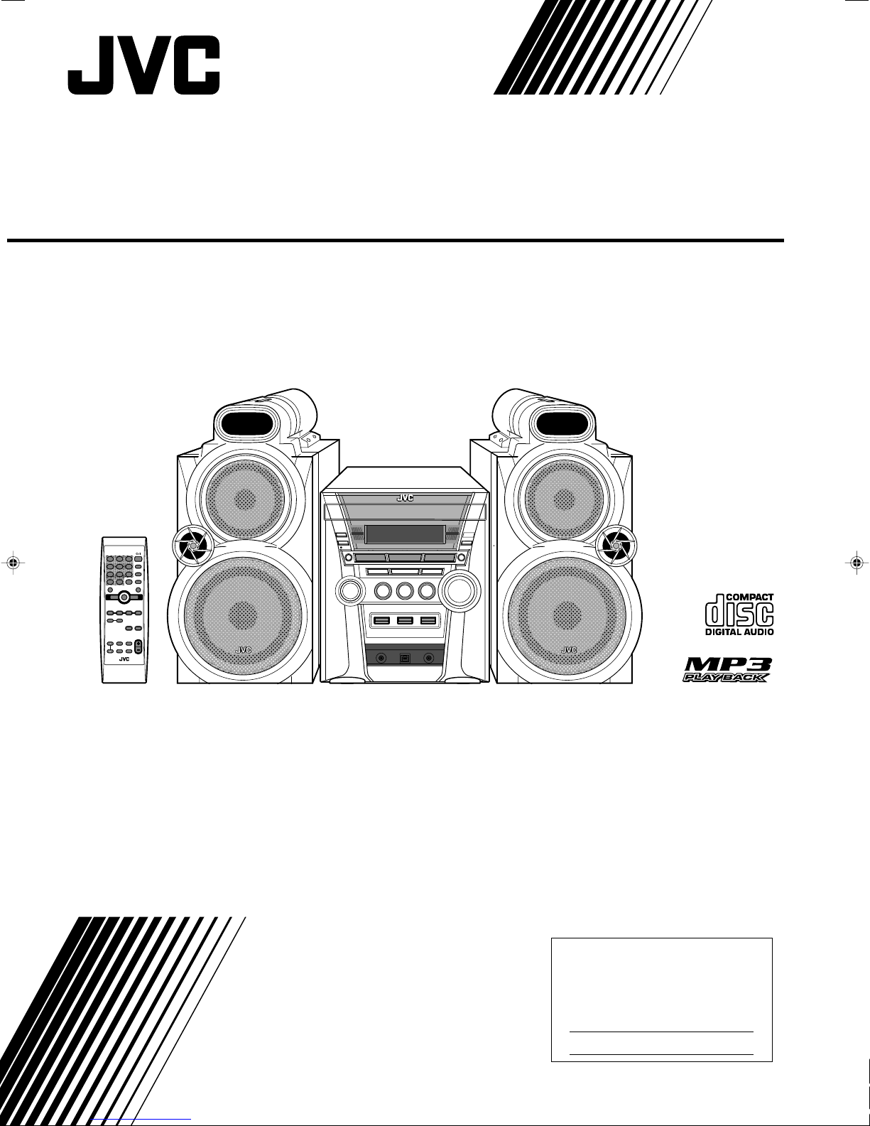
MX-GC5
—Consists of CA-MXGC5 and SP-MXGC5
COMPACT COMPONENT SYSTEM
MX-GC5 COMPACT COMPONENT SYSTEM
INSTRUCTIONS
LVT1344-001A
[J]
For Customer Use:
Enter below the Model No. and Serial
No. which are located either on the rear,
bottom or side of the cabinet. Retain this
information for future reference.
Model No.
Serial No.
SP-MXGC5 SP-MXGC5CA-MXGC5
Page 2
Warnings, Cautions and Others
CAUTION: TO REDUCE THE RISK OF ELECTRIC SHOCK.
DO NOT REMOVE COVER (OR BACK)
NO USER SERVICEABLE PARTS INSIDE.
REFER SERVICING TO QUALIFIED SERVICE PERSONNEL.
RISK OF ELECTRIC SHOCK
DO NOT OPEN
The lightning flash with arrowhead symbol,
within an equilateral triangle is intended to
alert the user to the presence of uninsulated
“dangerous voltage” within the product's
enclosure that may be of sufficient
magnitude to constitute a risk of electric
shock to persons.
The exclamation point within an equilateral
triangle is intended to alert the user to the
presence of important operating and
maintenance (servicing) instructions in the
literature accompanying the appliance.
CAUTION
For U.S.A.
This equipment has been tested and found to comply with the limits
for a Class B digital device, pursuant to part 15 of the FCC Rules.
These limits are designed to provide reasonable protection against
harmful interference in a residential installation.
This equipment generates, uses and can radiate radio frequency
energy and, if not installed and used in accordance with the
instructions, may cause harmful interference to radio
communications. However, there is no guarantee that interference
will not occur in a particular installation. If this equipment does cause
harmful interference to radio or television reception, which can be
determined by turning the equipment off and on, the user is
encouraged to try to correct the interference by one or more of the
following measures:
Reorient or relocate the receiving antenna.
Increase the separation between the equipment and receiver.
Connect the equipment into an outlet on a circuit different from that
to which the receiver is connected.
Consult the dealer or an experienced radio/TV technician for help.
WARNING: TO REDUCE THE RISK OF FIRE
OR ELECTRIC SHOCK, DO NOT EXPOSE
THIS APPLIANCE TO RAIN OR MOISTURE.
Mises en garde, précautions et indications diverses
CAUTION
Changes or modifications not approved by JVC could void the
user’s authority to operate the equipment.
For the main unit:
Declaration of Conformity
Model Number: MX-GC5
Trade Name: JVC
Responsible Party: JVC Americas Corp.
CAUTION
To reduce the risk of electrical shocks, fire, etc.:
1. Do not remove screws, covers or cabinet.
2. Do not expose this appliance to rain or moisture.
ATTENTION
Afin d’éviter tout risque d’électrocution, d’incendie, etc.:
1. Ne pas enlever les vis ni les panneaux et ne pas
ouvrir le coffret de l’appareil.
2. Ne pas exposer l’appareil à la pluie ni à l’humidité.
Address: 1700 Valley Road, Wayne
Telephone Number: 973-317-5000
This device complies with Part 15 of FCC Rules. Operation is
subject to the following two conditions: (1) This device may
not cause harmful interference, and (2) this device must
accept any interference received, including interference that
may cause undesired operation.
For Canada/pour le Canada
CAUTION: TO PREVENT ELECTRIC SHOCK, MATCH WIDE
BLADE OF PLUG TO WIDE SLOT, FULLY INSERT.
ATTENTION: POUR EVITER LES CHOCS ELECTRIQUES,
INTRODUIRE LA LAME LA PLUS LARGE DE LA FICHE DANS
LA BORNE CORRESPONDANTE DE LA PRISE ET POUSSER
JUSQUAU FOND.
New Jersey 07470
G-1
Note to CATV system installer:
This reminder is provided to call the CATV system installer’s
attention to section 820-40 of the NEC which provides guidelines
for proper grounding and, in particular, specifies that the cable
ground shall be connected to the grounding system of the building,
as close to the point of cable entry as practical.
For Canada/pour le Canada
THIS DIGITAL APPARATUS DOES NOT EXCEED THE CLASS B
LIMITS FOR RADIO NOISE EMISSIONS FROM DIGITAL
APPARATUS AS SET OUT IN THE INTERFERENCE-CAUSING
EQUIPMENT STANDARD ENTITLED “DIGITAL APPARATUS,”
ICES-003 OF THE DEPARTMENT OF COMMUNICATIONS.
CET APPAREIL NUMERIQUE RESPECTE LES LIMITES DE
BRUITS RADIOELECTRIQUES APPLICABLES AUX APPAREILS
NUMIRIQUES DE CLASSE B PRESCRITES DANS LA NORME
SUR LE MATERIEL BROUILLEUR: “APPAREILS NUMERIQUES”,
NMB-003 EDICTEE PAR LE MINISTRE DES
COMMUNICATIONS.
Page 3
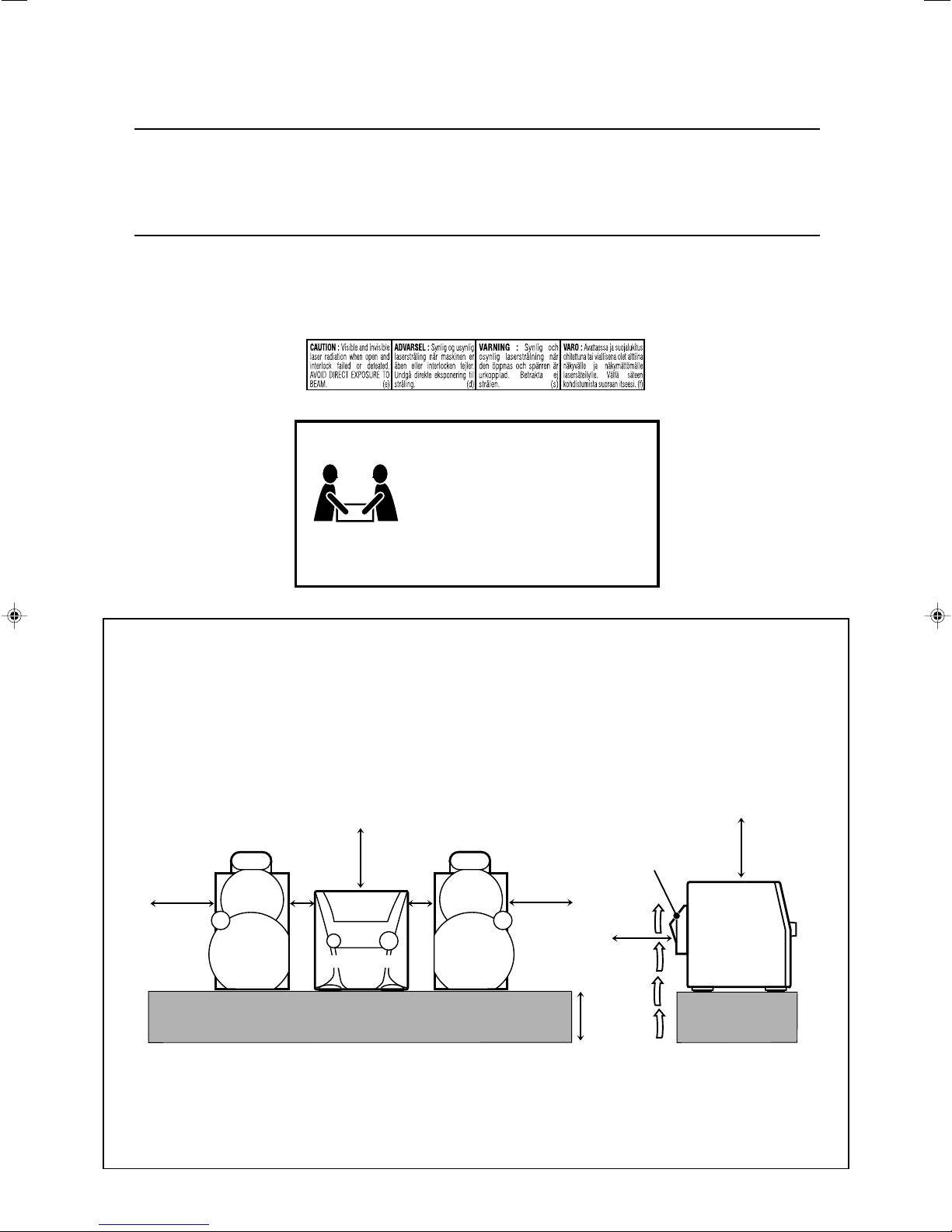
IMPORTANT FOR LASER PRODUCTS
CAUTION!
To avoid personal injury or accidentally
dropping the unit, have two persons unpack,
carry, and install the unit.
ATTENTION!
Pour éviter toute blessure personnelle ou
chute accidentelle de lappareil, faites
déballer, transporter et installer lappareil
par deux personnes.
24.0 kg / 53 lbs
1. CLASS 1 LASER PRODUCT
2. CAUTION: Do not open the top cover. There are no user serviceable parts inside the unit; leave all servicing to qualified service
personnel.
3. CAUTION: Visible and invisible laser radiation when open and interlock failed or defeated. Avoid direct exposure to beam.
4. REPRODUCTION OF LABEL: CAUTION LABEL, PLACED INSIDE THE UNIT.
IMPORTANT POUR PRODUITS LASER
1. PRODUIT LASER CLASSE 1
2. ATTENTION: N’ouvrez pas le couvercle supérieur. Il n’y a aucune pièce réparable par l’utilisateur à l’intérieur de l’appareil;
confiez toute réparation à un personnel qualifié.
3. ATTENTION: Risque de radiations laser visible et invisible quand l’appareil est ouvert et que le système de verrouillage ne
fonctionne pas ou a été mis hors service. Évitez toute exposition directe au rayon.
4. REPRODUCTION DE L’ÉTIQUETTE: ÉTIQUETTE DE PRÉCAUTION PLACÉE À L’INTERIEUR DE L’APPAREIL.
Caution: Proper Ventilation
To avoid risk of electric shock and fire, and to prevent damage,
locate the apparatus as follows:
1 Front:
No obstructions and open spacing.
2 Sides/ Top/ Back:
No obstructions should be placed in the areas shown by the
dimensions below.
3 Bottom:
Place on the level surface. Maintain an adequate air path for
ventilation by placing on a stand with a height of 10 cm or more.
Front view
Face
15 cm
15
(5
/16 in.)
SP-MXGC5
* About the cooling fan
A cooling fan is mounted on the rear panel of the unit to prevent abnormal temperature inside the unit, thus assuring normal operation of the
unit. The cooling fan automatically starts rotating to intake external cool air when the volume is increased up to more than a certain level.
* À propos du ventilateur de refroidissement
Un ventilateur de refroidissement se trouve sur le panneau arrière de l’appareil afin d’éviter la création d’une température anormale à l’intérieur
de l’appareil et permettre ainsi un fonctionnement normal de l’appareil. Le ventilateur de refroidissement commence à tourner et à aspirer de
l’air frais automatiquement quand le volume est augmenté au-dessus d’un certain niveau.
7
(
1 cm
/16 in.)
15 cm
15
(5
CA-MXGC5
/16 in.)
(7/16 in.)
1 cm
Attention: Aération correcte
Pour prévenir tout risque de décharge électrique ou d’incendie et éviter
toute détérioration, installez l’appareil de la manière suivante:
1 Avant:
Bien dégagé de tout objet.
2 Côtés/dessus/dessous:
Assurez-vous que rien ne bloque les espaces indiqués sur le
schéma ci-dessous.
3 Dessous:
Posez l’appareil sur une surface plane et horizontale. Veillez à ce
que sa ventilation correcte puisse se faire en le plaçant sur un
support d’au moins dix centimètres de hauteur.
Side view
Côté
Cooling fan*
15 cm
(5
SP-MXGC5
Ventilateur de refroidissement*
15
/16 in.)
15 cm
15
(5
/16 in.)
10 cm
15
(3
/16 in.)
CA-MXGC5
15 cm
(5
15
/16 in.)
G-2
Page 4
Introduction
We would like to thank you for purchasing one of our JVC products.
Before operating this unit, read this manual carefully and thoroughly to
obtain the best possible performance from your unit, and retain this manual
for future reference.
About This Manual
This manual is organized as follows:
• The manual mainly explains operations using the
buttons and controls on the remote control. You can also
use the buttons on the unit if they have the same or
similar names (or marks) as those on the remote
control.
If operation using the unit is different from that using
the remote control, it is then explained.
• Basic and common information that is the same for many
functions is grouped in one place, and is not repeated in
each procedure. For instance, we do not repeat the
information about turning on/off the unit, setting the
volume, changing the sound effects, and others, which are
explained in the section “Common Operations” on pages
10 to 12.
• The following marks are used in this manual:
Gives you warnings and cautions to prevent
damage or risk of fire/electric shock.
Also gives you information which is not good
for obtaining the best possible performance
from the unit.
Gives you information and hints you had better
know.
Power sources
• When unplugging from the wall outlet, always pull the
plug, not the AC power cord.
DO NOT handle the AC power cord with wet
hands.
Moisture condensation
Moisture may condense on the lens inside the unit in the
following cases:
• After starting heating in the room
• In a damp room
• If the unit is brought directly from a cold to a warm place
Should this occur, the unit may malfunction. In this case,
leave the unit turned on for a few hours until the moisture
evaporates, unplug the AC power cord, and then plug it in
again.
Others
• Should any metallic object or liquid fall into the unit,
unplug the unit and consult your dealer before operating
any further.
• If you are not going to operate the unit for an extended
period of time, unplug the AC power cord from the wall
outlet.
DO NOT disassemble the unit since there are no
user serviceable parts inside.
Precautions
Installation
• Do not grasp the control knobs when moving or carrying
the unit.
• Install in a place which is level, dry and neither too hot nor
too cold—between 5˚C and 35˚C (41˚F and 95˚F).
• Install the unit in a location with adequate ventilation to
prevent internal heat built-up in the unit.
• Leave sufficient distance between the unit and the TV.
• Keep the speakers away from the TV to avoid interference
with TV.
DO NOT install the unit in a location near heat
sources, or in a place subject to direct sunlight,
excessive dust or vibration.
1
If anything goes wrong, unplug the AC power cord and
consult your dealer.
Page 5
Contents
Location of the Buttons and Controls ....................... 3
Getting Started............................................................ 6
Unpacking .................................................................. 6
Putting the Batteries into the Remote Control ........... 6
Connecting Antennas ................................................. 6
Connecting Speakers .................................................. 7
Connecting Other Equipment ..................................... 8
Canceling the Display Demonstration ....................... 8
Saving the Power Consumption while on Standby—
ECO mode ............................................................ 8
Connecting a Computer.............................................. 9
Common Operations ................................................ 10
Turning On or Off the Power ................................... 10
Setting the Clock ...................................................... 10
Selecting the Sources ............................................... 10
Adjusting the Volume ............................................... 11
Reinforcing the Bass Sound ..................................... 11
Enjoying the Powerful Sound—RHYTHM AX ....... 11
Selecting the Sound Modes ...................................... 12
Turning On or Off the Key-touch Tone .................... 12
Listening to the Radio .............................................. 13
Tuning in to a Station—Auto Search ....................... 13
Presetting Stations .................................................... 13
Tuning in to a Preset Station .................................... 13
Playing Back CDs ..................................................... 14
Loading discs ........................................................... 14
Continuous Playback ................................................ 14
Basic CD Operations ................................................ 16
Changing the MP3 Playback Mode.......................... 17
Turning On or Off the Resume Play for MP3 Disc ...
Programming the Playing Order of the Tracks—
Program Play ...................................................... 18
Playing at Random—Random Play ......................... 19
Repeating Tracks or CDs—Repeat Play .................. 19
Prohibiting Disc Ejection—Carrousel Lock ............ 19
17
Using the Timers ....................................................... 20
Using Daily Timer .................................................... 20
Using Sleep Timer .................................................... 21
Troubleshooting ........................................................ 22
Maintenance .............................................................. 23
Specifications............................................................. 24
2
Page 6
Location of the Buttons and Controls
2
1
3
4
5
6
7
8
9
q
p
w
r
y
t
u
i
e
o
;
a
s
Become familiar with the buttons and controls on your unit.
Front Panel
3
Page 7
Display Window
1
4
23
65
78 0 -=
9
Continued
See pages in the parentheses for details.
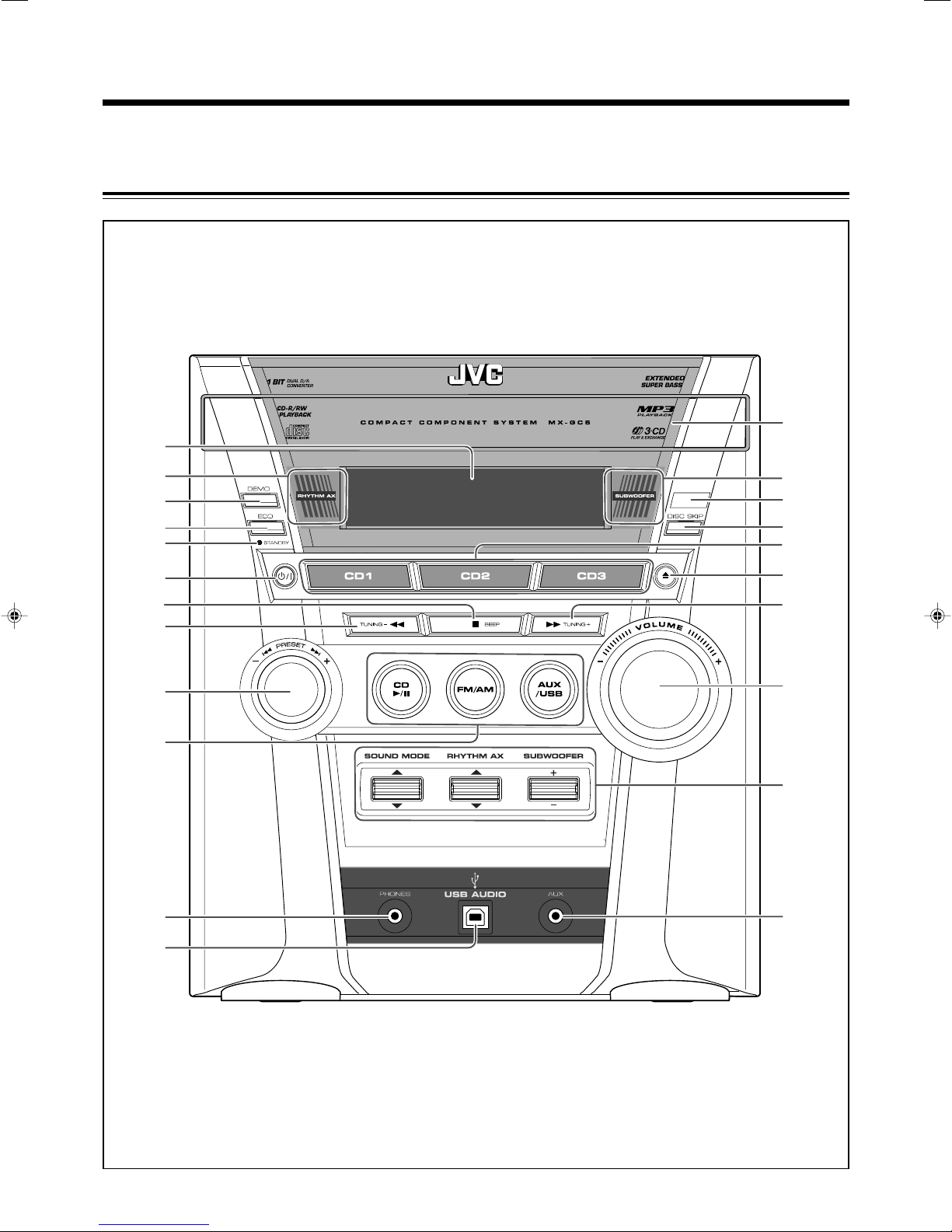
Front Panel
1 Display window
2 RHYTHM AX lamp (11)
3 DEMO button (8)
4 ECO button (8)
5 STANDBY lamp (10)
6 (standby/on) button (10)
7 • 7 (stop) button (15, 19)
• BEEP button (12)
8 • TUNING – button (13)
• 1 (fast reverse) button (16)
9 • PRESET +/– control (13)
• ¢ / 4 (forward search/reverse search) control
(16, 17)
p Source selecting buttons
• CD 6 (play/pause) button (10, 14, 15, 16)
• FM/AM button (10, 13)
• AUX/USB button (8 – 10)
Pressing one of these buttons also turns on the unit.
q PHONES jack (11)
w USB AUDIO terminal (9)
e Carrousel
r SUBWOOFER lamp (11)
t Remote sensor (5)
y DISC SKIP button (14, 16)
u Disc tray selecting buttons and lamps (10, 14 – 16)
• CD1, CD2, and CD3 buttons
Pressing one of these buttons also turns on the unit.
i 0 (carrousel open/close) button (14 – 16, 19)
Pressing this button also turns on the unit.
o • TUNING + button (13)
• ¡ (fast forward) button (16)
; VOLUME +/– control (11)
a Sound effect controls
• SOUND MODE control (12)
• RHYTHM AX control (11)
• SUBWOOFER +/– control (11)
s AUX jack (8)
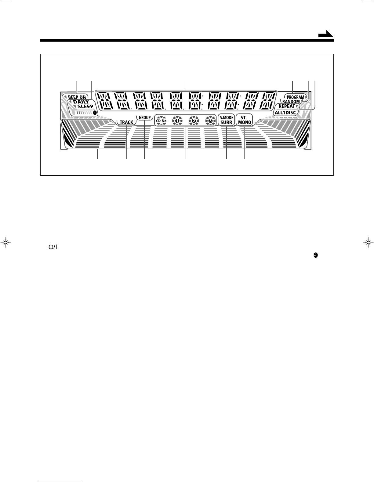
Display Window
1 BEEP ON indicator
2 Timer indicators
• DAILY (daily timer), SLEEP (sleep timer), and
(timer) indicators
3 Main display
• Shows the source name, frequency, etc.
4 PROGRAM indicator
5 RANDOM indicator
6 REPEAT mode indicators
• REPEAT ALL, 1, DISC indicators
7 Volume level, Subwoofer level and Sound mode pattern
indicators
8 TRACK indicator
9 GROUP indicator
0 Disc tray number (CD No., 1, 2, and 3) indicators
• Shows tray and playback conditions.
- Sound effect indicators
• S.MODE (sound mode) and SURR. (surround)
indicators
= Tuner operation indicators
• ST (stereo) and MONO indicators
4
Page 8
Remote Control
3
4
5
6
7
8
9
p
q
w
e
r
o
t
y
;
a
s
u
i
d
1
2
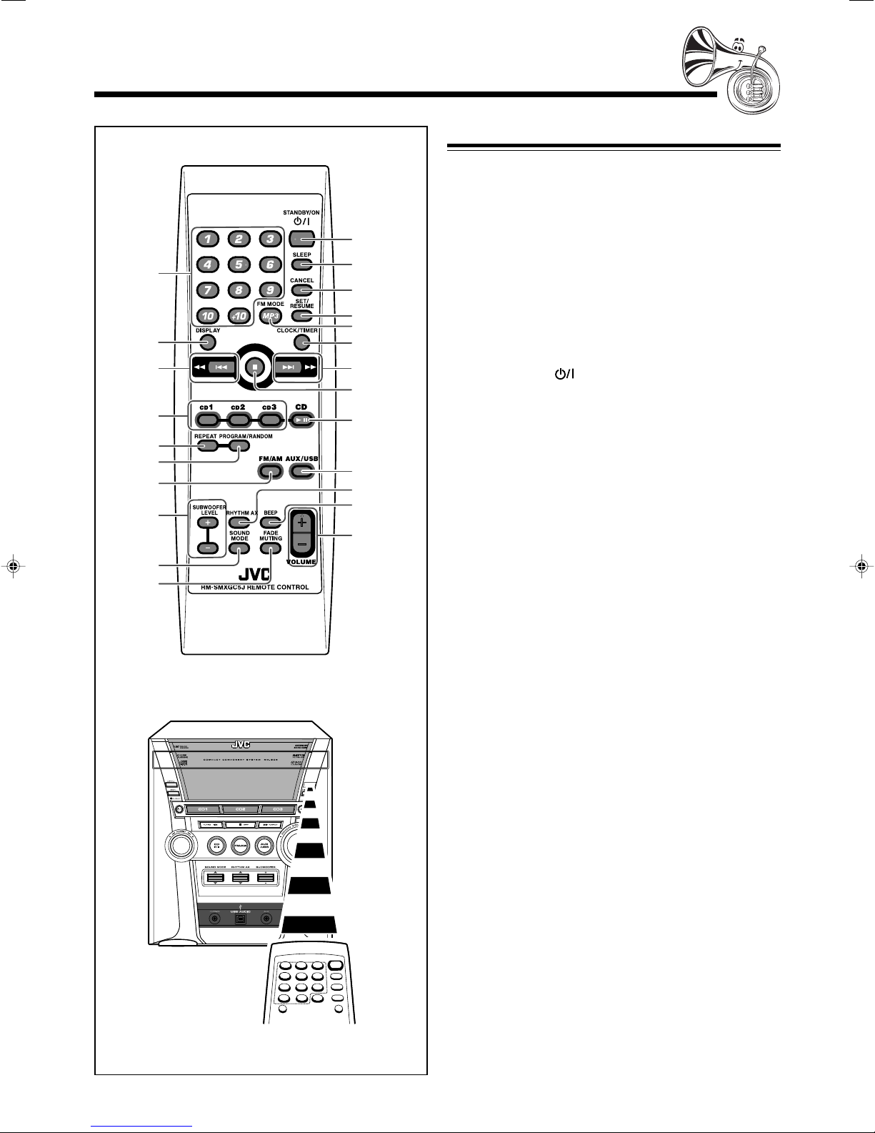
Remote Control
1 Number buttons (13, 17, 18)
2 DISPLAY button (10)
3 4/1 (reverse search/fast reverse) button
(10, 13, 16 – 18, 20, 21)
4 Disc tray selecting buttons (10, 14 – 16, 18, 19)
• CD1, CD2, and CD3 buttons
5 REPEAT button (19)
6 PROGRAM/RANDOM button (18, 19)
7 FM/AM button (10, 13)
Pressing this button also turns on the unit.
8 SUBWOOFER LEVEL +/– buttons (11)
9 SOUND MODE button (12)
p FADE MUTING button (11)
q STANDBY/ON button (10, 21)
w SLEEP button (21)
e CANCEL button (10, 18, 20, 21)
r SET/RESUME button (10, 13, 17, 20, 21)
t • FM MODE button (13)
• MP3 button (17)
y CLOCK/TIMER button (10, 20, 21)
u ¢/¡ (forward search/fast forward) button
(10, 13, 16 – 18, 20, 21)
i 7 (stop) button (15, 18, 19)
o CD 6 (play/pause) button (10, 14 – 18)
Pressing this button also turns on the unit.
; AUX/USB button (8 – 10)
Pressing this button also turns on the unit.
a RHYTHM AX button (11)
s BEEP button (12)
d VOLUME +/– button (11)
5
When using the remote control, point it at
the remote sensor on the front panel.
Page 9
FM coaxial
AM
LOOP
GND
AM EXT
(75 )
ANTENNA
Getting Started
AM
LOOP
GND
AM EXT
ANTENNA
FM coaxial
(75 )
Do not connect the AC power cord until all other
connections have been made.
Continued
Unpacking
After unpacking, check to be sure that you have all the
following items.
The number in the parentheses indicates the quantity of each
piece supplied.
• FM antenna (1)
• AM loop antenna (1)
• Remote control (1)
• Batteries (2)
If any is missing, consult your dealer immediately.
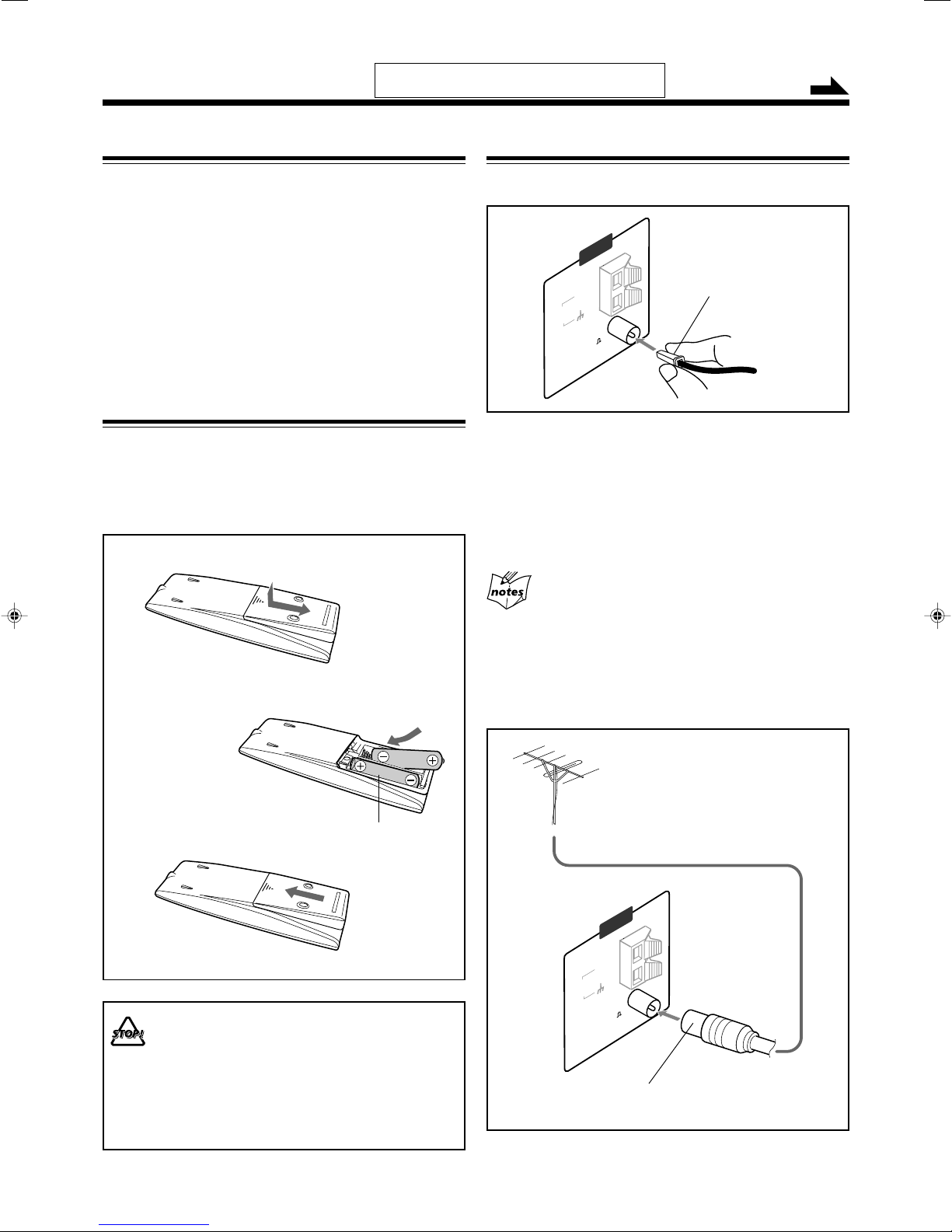
Putting the Batteries into the Remote Control
Insert the batteries—R6P(SUM-3)/AA(15F)—into the remote
control, by matching the polarity (+ and –) on the batteries
with the + and – markings on the battery compartment.
When the remote control can no longer operate the unit,
replace both batteries at the same time.
1
Connecting Antennas
FM antenna
FM antenna (supplied)
1
Attach the FM antenna to the FM [75 Ω]
coaxial terminal.
2
Extend the FM antenna.
3
Fasten it up in the position which gives you
the best reception, then fix it on the wall, etc.
2
R6P(SUM-3)/AA(15F)
3
• DO NOT use an old battery together with a new one.
• DO NOT use different types of batteries together.
• DO NOT expose batteries to heat or flame.
• DO NOT leave the batteries in the battery
compartment when you are not going to use the
remote control for an extended period of time.
Otherwise, the remote control will be damaged from
battery leakage.
About the supplied FM antenna
The FM antenna supplied with this unit can be used as temporary
measure. If reception is poor, you can connect an outdoor FM
antenna (not supplied).
To connect an outdoor FM antenna
Before connecting it, disconnect the supplied FM antenna.
Outdoor FM antenna
(not supplied)
A 75 Ω antenna with coaxial type connector should be
used.
6
Page 10
MAIN SPEAKER
SUB-WOOFER
6–16 6–16
RIGHT
LEFT
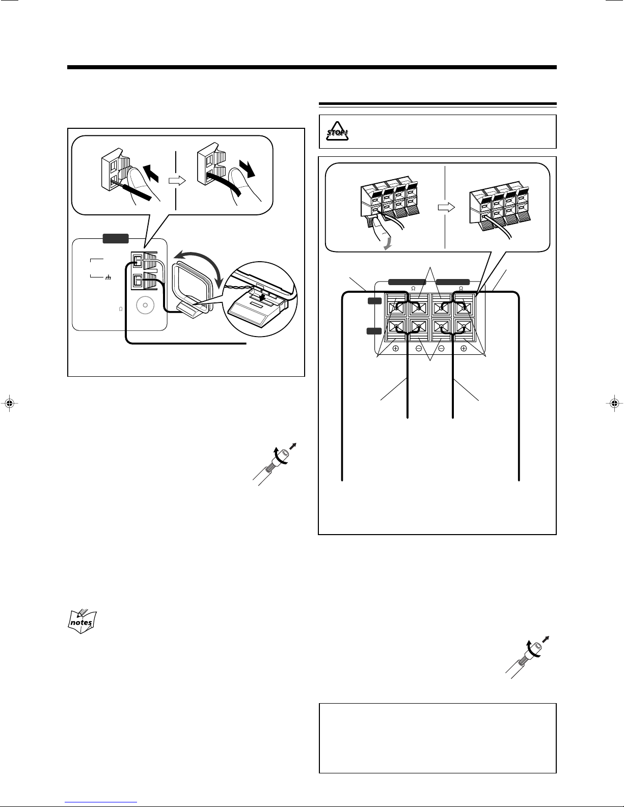
AM antenna
AM
LOOP
FM coaxial
GND
AM EXT
(75 )
ANTENNA
Make sure to connect the wire correctly: The white end to
AM EXT, the black end to GND.
1, 2
3
Connecting Speakers
DO NOT carry the speaker by holding the tube
duct (on the top of the speaker).
AM loop antenna
4
(supplied)
Vinyl-covered wire
(not supplied)
1
Press and hold the clamp of the AM terminal
on the rear of the unit.
2
Insert the end of the AM loop antenna cord
into the terminal.
• If the AM loop antenna wire is covered
with vinyl, remove the vinyl by twisting it
as shown in the diagram.
3
Release the finger from the clamp.
4
Turn the AM loop antenna until you have the
best reception.
To connect an outdoor AM antenna
When reception is poor, connect a single vinyl-covered wire
to the AM terminal and extend it horizontally. (The AM loop
antenna must remain connected.)
• Make sure the antenna conductors do not touch any other
terminals and connecting cords.
• Keep the antennas away from metallic parts of the unit,
connecting cords, and the AC power cord.
For better reception of both FM and AM
1, 2
Speaker cord
(blue/black)
Blue
Speaker cord
(blue/black)
From right
speaker’s
terminals
From left
main
speaker’s
terminals
1
Press and hold the clamp of the speaker
Black
Black
main
3
Speaker
cord
(red/black)
Red
Speaker cord
(red/black)
From right
subwoofer’s
terminals
From left
subwoofer’s
terminals
terminal on the rear of the unit.
2
Insert the end of the speaker cord into the
terminal.
Match the colors (polarity): Blue (+) to blue (+) and black
(–) to black (–); red (+) to red (+) and black (–) to black
(–).
• If the wire is covered with vinyl, remove
the vinyl by twisting it as shown in the
diagram.
7
3
Release the finger from the clamp.
IMPORTANT:
• Use only speakers with the same speaker impedance as
indicated by the speaker terminals on the rear of the
unit.
• DO NOT connect more than one speaker to one speaker
terminal.
Page 11

Continued
Connecting Other Equipment
You can connect audio equipment—used only as a playback
device.
• DO NOT connect any equipment while the power
is on.
• DO NOT plug in any equipment until all
connections are complete.
To connect audio equipment
Stereo mini plug cord (not supplied)
Audio equipment
To audio output
NOW you are ready to plug in the unit and
other connected equipment.
Canceling the Display Demonstration
When connecting the AC power cord into a wall outlet, the
unit automatically starts the display demonstration.
On the unit ONLY:
To cancel the display demonstration, press
DEMO while the display demonstration is
shown on the display.
When you press other buttons
The display demonstration stops temporarily. It will start
automatically again (if no operation is done for 2 minutes) until you
cancel it.
To start the display demonstration manually
Press and hold DEMO again for more than 2
seconds.
For playing the other equipment through this unit,
connect between the audio output jack on the other
equipment and AUX jack on the front of the unit by using a
stereo mini plug cord (not supplied).
If the audio output on the other equipment is not
stereo mini plug type
Use a plug adapter to convert the stereo mini plug to the
corresponding plug of the audio output.
Saving the Power Consumption while on
Standby—ECO mode
You can save the power consumption while the unit is turned
off (on standby).
On the unit ONLY:
To activate the ECO mode, press ECO while the
unit is turned off (on standby).
“ECO MODE” appears on the display illumination
(including the display demonstration) disappears.
To deactivate the ECO mode, press ECO again.
The display illumination appears.
About ECO mode
While ECO mode is activated, the display demonstration is canceled
temporarily.
8
Page 12

Connecting a Computer
This unit is equipped with a USB AUDIO terminal on the front
panel.
You can connect your PC to this terminal and enjoy sound
reproduced through your PC.
When you connect your PC for the first time, follow the procedure
below.
• Remember you cannot send any signal or data to your PC from
this unit.
IMPORTANT:
• Check if your PC equipped with the CD-ROM drive is
running on Windows
XP* and prepare its CD-ROM.
• Check your PC’s BIOS setting—whether USB is
available, and whether USB IRQ is set to “AUTO ” or to
available IRQ number.
How to install the USB drivers
The following procedure is described using the English version of
Windows
operation system or language, the screens shown on your PC’s
monitor will differ from the ones used in the following procedure.
1
®
XP. If your PC is running on a different version of
Turn on your PC and start running Windows® 98,
Windows® 98 SE, Windows® Me, Windows® 2000, or
Windows® XP.
• If the PC has been turned on, quit all the applications now
running.
2
Select “USB IN” as the source.
3
Set the volume to minimum.
®
98*, Windows® Me* or Windows
®
5
The USB drivers are installed automatically.
• If the USB drivers are not installed automatically, install the
USB drivers by following the instructions on the PC’s monitor.
6
Check if the drivers are correctly installed.
1. Open the Control Panel on your PC:
Select [Start] = [Control Panel].
2. Select [System] = [Hardware] = [Device Manager] =
[Sound, video and game controllers] and [Universal Serial
Bus controllers].
• The following window appears, and you can check whether
the drivers are installed.
IMPORTANT:
• Always set volume to “VOL MIN” when connecting or
disconnecting the other equipment.
4
Connect the unit to the PC using a USB cable (not
supplied).
Your PC automatically recognizes this connection, and shows
the following screen on the monitor.
PC
USB cable
• Use “USB series A plug to B plug” cable when connecting.
Now PC is ready for playback through the USB connection.
After installation is completed, you can use your PC as the playback
source. The PC automatically recognizes the unit whenever a USB
cable is connected between the PC and the unit while the unit is
turned on.
• When not using the PC as the playback source, disconnect the
USB cable.
To play back sounds on the PC, refer to the manuals supplied with
the sound reproduction application installed in the PC.
• DO NOT turn off the unit or disconnect the USB cable while
installing the drivers and for several seconds while your PC is
recognizing the receiver.
• Use a full speed USB cable (version 1.1). Recommended cord
length is 1.5 m.
• If your PC does not recognize the unit, disconnect the USB cable
and connect it again. If it does not work yet, restart Windows.
• The installed drivers can be recognized only when the USB cable
is connected between the unit and your PC.
• The sound may not be played back correctly—interrupted or
degraded—due to your PC settings and PC specifications.
®
* Microsoft
Windows
Microsoft corporation.
, Windows® 98, Windows® SE, Windows® Me,
®
2000, and Windows® XP are registered trademarks of
9
Page 13

Common Operations
ON TIME DAILY
CLOCK
Continued
Turning On or Off the Power
To turn on the unit, press STANDBY/ON (or
on the unit) so that the STANDBY lamp goes
off.
To turn off the unit (on standby), press
STANDBY/ON (or on the unit) again
so that the STANDBY lamp lights up.
A little power is always consumed even while
the unit is on standby.
To switch off the power supply completely, unplug the AC
power cord from the AC outlet.
When you unplug the AC power cord or if a power
failure occurs
The clock is reset to “AM 12:00” right away, while the tuner preset
stations (see page 13) will be erased in a few days.
3
Press ¢ or 4 to
adjust the minute, then
press SET/RESUME.
To check the clock time
Press DISPLAY while playing any source.
• To return to the source indication, press
DISPLAY again.
While the time indication appears on the display
If you press a button or turn a control, the time indication returns to
the source indication.
To adjust the clock again
1
Press CLOCK/TIMER repeatedly until
“CLOCK” is selected.
• Each time you press the button, the clock/
timer setting modes change as follows:
Setting the Clock
Before operating the unit any further, first set the clock built
in this unit. You can set the clock whether the unit is on or
off.
On the remote control ONLY:
1
Press CLOCK/TIMER.
The hour digits start flashing on the display.
2
Press ¢ or 4 to adjust
the hour, then press SET/
RESUME.
The minute digits start flashing on
the display.
• If you want to correct the hour after pressing SET/
RESUME, press CANCEL. The hour digits start
flashing again.
Canceled
2
Press SET/RESUME.
3
Perform steps 2 and 3 of “Setting the Clock.”
When you unplug the AC power cord or if a power
failure occurs
The clock loses the setting and is reset to “AM 12:00.” You need to
set the clock again.
Selecting the Sources
To listen to the radio, press FM/AM. (See page 13.)
To play back CDs, press CD 6 or CD1, CD2, CD3. (See
pages 14 – 19.)
To select the external equipment as the source,
press AUX/USB. (See pages 8 and 9.)
When you press the play button for a particular source
(FM/AM, CD 6, and AUX/USB), the unit turns on and the
unit starts playing the source if it is ready.
• The selected source lamp lights up.
10
Page 14

Adjusting the Volume
Reinforcing the Bass Sound
You can adjust the volume level only while the unit is turned
on.
Press VOLUME + to increase the volume or
press VOLUME – to decrease it.
• The volume level can be adjusted in 33 steps
(VOL MIN, VOL 1 — VOL 31, and VOL
MAX).
When using the unit, turn the VOLUME control clockwise to
increase the volume or counterclockwise to decrease it.
For private listening
Connect a pair of headphones to the PHONES jack. No sound
comes out of the speakers. Be sure to turn down the volume before
connecting or putting on headphones.
Always set the volume to the minimum before
starting any source. If the volume is set to
extremely high level, a sudden blast of sound can
damage your hearing, speakers and/or
headphones.
• If you have turned off (on standby) the unit with
the volume level set at more than level “15,” the
volume level will be automatically set at level “15”
next time you turn on the unit.
Press SUBWOOFER LEVEL + or – (or
SUBWOOFER +/– control on the unit) to
increase or decrease the subwoofer sound.
• The subwoofer level can be adjusted
in 3 steps (OFF, S.WOOFER1, S.WOOFER2).
The SUBWOOFER lamp also lights up.
Enjoying the Powerful Sound—RHYTHM AX
Using RHYTHM AX, harder-hitting beats intensify your
listening experience even at low sound levels.
RHYTHM AX also works even when the song has no “beat,”
such as classical music, so that you can listen to the rich
sound even at low sound levels.
On the remote control:
Press RHYTHM AX.
“RHYTHM AX” scrolls on the display.
• Each time you press the button, RHYTHM AX
turns on and off alternately. The RHYTHM AX
lamp also lights up.
To turn down the volume level temporarily
Press FADE MUTING on the remote control.
The volume level gradually decreases to
“VOL MIN.”
To restore the sound, press the button again.
On the unit:
Press up the RHYTHM AX control to turn
on or press down the RHYTHM AX control
to turn off.
11
Page 15
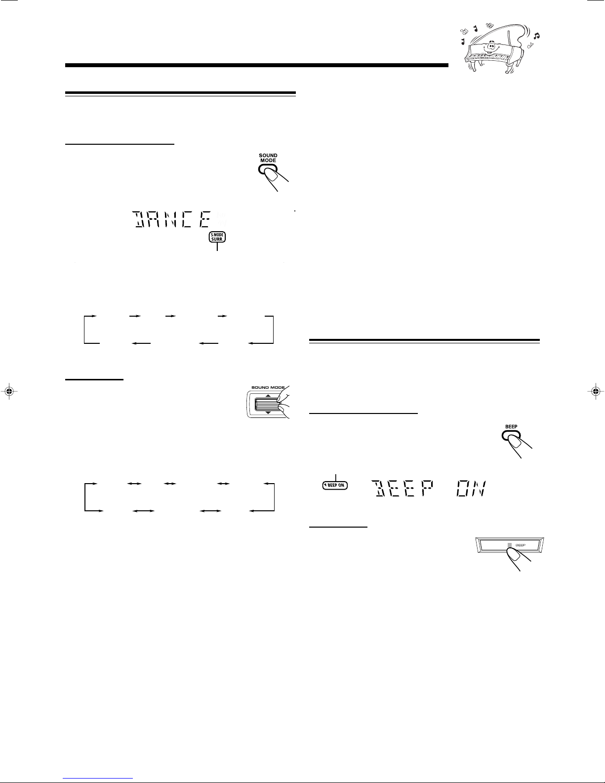
Selecting the Sound Modes
ROCK
FLAT
POP CLASSIC DANCE
HALL
STADIUM
ROCK
FLAT
POP CLASSIC DANCE
HALL
STADIUM
You can select one of the 6 preset sound modes (3 surround
modes and 3 SEA—Sound Effect Amplifier—modes).
On the remote control:
Press SOUND MODE repeatedly until the
sound mode you want appears on the display.
• First time you press the button, the current
sound mode appears on the display.
The S.MODE and SURR. indicators also light up on
the display
Each time you press the button while a sound mode appears
on the display, the sound modes change as follows:
SEA (Sound Effect Amplifier) modes*1:
ROCK : Boosts low and high frequency. Good for
acoustic music.
POP : Good for vocal music.
CLASSIC : Good for classical music.
FLAT : Cancels the sound mode.
Surround modes*2:
DANCE : Increases resonance and bass.
HALL : Adds depth and brilliance to the sound.
STADIUM: Adds clarity and spreads the sound, like in an
outdoor stadium.
*1While one of the SEA modes (SEA elements without surround
elements) is selected, the S.MODE indicator lights up.
2
*
Surround elements are added to the SEA elements to create
being-there feeling in your room.
When one of these modes is selected, the S.MODE and SURR.
indicators light up.
Turning On or Off the Key-touch Tone
(Canceled)
On the unit:
Press up or down the SOUND MODE
control until the sound mode you want
appears on the display.
• First time you press up or down the control,
the current sound mode appears on the display.
Each time you press up or down the control while a sound
mode appears on the display, the sound modes change as
follows:
(Canceled)
If you do not want the key-touch tone to beep each time you
press a button or turn a control, you can deactivate it.
• You can turn on or off the key-touch tone whether the unit
is on or off.
On the remote control:
Press BEEP.
• Each time you press the button, the key-touch
tone turns on and off alternately.
The BEEP ON indicator also lights up on the display
On the unit:
Press and hold BEEP for more than 2
seconds.
• Each time you press and hold the button,
the key-touch tone turns on and off
alternately.
12
Page 16

Listening to the Radio
Tuning in to a Station—Auto Search
1
Press FM/AM.
The unit automatically turns on and tunes in to
the previously tuned station (either FM or AM).
• Each time you press the button, the band
alternates between FM and AM.
2
Start searching for stations.
On the remote control:
Press and hold ¢/¡ or
4/1 for more than 1
second.
On the unit:
Press and hold
TUNING + or TUNING
– for more than 1 second.
The unit starts searching for stations and stops when a
station of sufficient signal strength is tuned in.
If a program is broadcast in stereo, the ST (stereo)
indicator lights up.
To stop while searching, press ¢/¡ or 4/1 (or
TUNING + or TUNING – on the unit).
2
Press SET/RESUME on the remote
control.
3
Press the number button(s) to
select a preset number.
Ex.: For preset number 5, press 5.
For preset number 15,
press +10 then 5.
For preset number 20,
press +10, then 10.
For preset number 25, press +10, +10, then 5.
For preset number 30, press +10, +10, then 10.
4
Press SET/RESUME on the remote
control again.
When you press ¢/¡ or 4/1
(or TUNING + or TUNING – on the unit) briefly and
repeatedly
The frequency changes step by step.
To change the FM reception mode
When an FM stereo broadcast is hard to receive or
noisy, press FM MODE on the remote control so
that “MONO” appears and the MONO indicator
also lights up on the display. Reception improves.
To restore the stereo effect, press FM MODE again so that
“STEREO” appears on the display.
Presetting Stations
You can preset 30 FM and 15 AM stations.
In some cases, test frequencies have been already memorized
for the tuner since the factory examined the tuner preset
function before shipment. This is not a malfunction. You can
preset the stations you want into memory by following the
presetting method.
•
There is a time limit in doing the following steps. If the
setting is canceled before you finish, start from step 2 again.
On the remote control ONLY:
1
Tune in to the station you want to preset (in
this example, of FM 87.5).
• See “Tuning in to a Station—Auto Search.”
The tuned station in step 1 is stored in the preset number
selected in step 3.
• Storing a new station on a used number erases the
previously stored one.
When you unplug the AC power cord or if a power
failure occurs
The preset stations will be erased in a few days. If this happens,
preset the stations again.
Tuning in to a Preset Station
1
Press FM/AM.
The unit automatically turns on and tunes in to
the previously tuned station (either FM or AM).
• Each time you press the button, the band
alternates between FM and AM.
2
Select a preset number.
On the remote control:
Press the number buttons.
Ex.: For preset number 5, press 5.
For preset number 15,
press +10 then 5.
For preset number 20,
press +10, then 10.
For preset number 25, press +10, +10, then 5.
For preset number 30, press +10, +10, then 10.
13
On the unit:
Turn PRESET +/– control to
select a preset number.
Page 17

Playing Back CDs
ReWritable
Recordable
Continued
This unit has been designed to playback the following CDs:
• Audio CD
• CD-R (CD-Recordable)
• CD-RW (CD-ReWritable)
• MP3 disc (MP3 files recorded on a CD-R or CD-RW)*
When playing a CD-R or CD-RW
• User-edited CD-Rs (CD-Recordable) and CD-RWs
(CD-ReWritable) can be played back when they are already
“finalized.”
• Before playing back CD-Rs or CD-RWs, read their instructions or
cautions carefully.
• Some CD-Rs or CD-RWs may not be played back on this unit
because of their disc characteristics, damage or stain on them, or
if the player’s lens is dirty.
Important notices:
• In general, you will have the best performance by keeping your
CDs and the mechanism clean.
Store CDs in their cases, and keep them in cabinets or on shelves.
–
– Keep the unit’s carrousel closed when not in use.
• Continuous use of irregular shaped discs (heart-shape, octagonal,
etc.) can damage the disc rotating mechanism.
• CD-RWs may require a longer readout time since the reflectance
of CD-RWs is lower than for regular CDs.
* For MP3 discs
• This unit manages files and folders on MP3 discs as “tracks” and
“albums.”
• The player can only recognize files with “.MP3” or “.mp3” as the
extensions, which can be in any combination of upper and lower
case. The file name needs to be up to 32 characters.
• This unit recognizes files and folders on a disc in the following
conditions:
– up to 500 MP3 files.
– up to 200 folders (including the root folder).
• Playback order of the MP3 files (tracks) recorded on a disc are
determined by the writing (or encoding) application; therefore,
playback order may be different from the one you have intended
while recording the files and the folders.
• This unit shows up to 30 characters of the file (track) names and
the ID3v1/1.1 tags (only “Title,” “Artist,” and “Album”) on the
display after the file starts play; however, there is a limitation on
available characters and some file names and ID3v1/1.1 tags are
not shown correctly.
More about MP3 discs
MP3 discs (either CD-R or CD-RW) require a longer readout time.
•
(It varies due to the complexity of the recording configuration.)
• When making an MP3 disc, select ISO 9660 Level 1 or Level 2 as
the disc format.
• This unit does not support multisession recording.
• This unit can play MP3 files only with the following file
extensions— “.MP3”, “.Mp3”, “.mP3”, and “.mp3”.
• Non-MP3 files are ignored. If non-MP3 files are recorded together
with MP3 files, this unit will take a longer time to scan the disc. It
may also cause the unit to malfunction.
• Some MP3 discs may not be played back because of their disc
characteristics or recording conditions.
Caution for DualDisc playback
The Non-DVD side of a “DualDisc” does not comply with the
“Compact Disc Digital Audio” standard. Therefore, the use of Non-
DVD side of a DualDisc on this product may not be recommended.
Loading discs
On the unit ONLY:
1
Press 0.
The unit automatically turns on and the
carrousel comes out.
• Pressing the button changes the playing source to “CD.”
2
Place one or two discs correctly on the front
recesses of the disc tray, with its label side up.
CORRECT
• When using a CD single (8 cm), place it on the inner
recess of the disc tray.
3
If you wish to load a third disc,
INCORRECT
press DISC SKIP.
The disc tray rotates by 120˚.
4
Press 0 again.
The carrousel closes.
To remove the disc, press 0
Continuous Playback
You can play discs continuously.
1
Load discs.
2
Press the corresponding
disc number button (CD1 –
CD3) to select the disc to
start playing back.
CD play starts from the first track of the selected disc.
• Pressing CD 6 instead of the disc number buttons
starts playing back if a disc is on the tray.
For Audio CD:
Current track number Elapsed playing time
14
Page 18
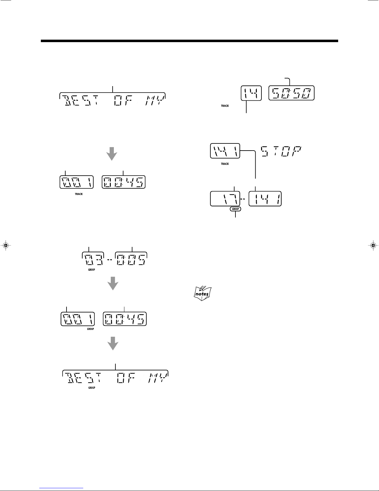
For MP3 disc:
• When the MP3 playback mode is the TRACK mode
(See also page 17.)
Current track name scrolls.
To stop during play, press 7.
For Audio CD:
Total playing time
When the track includes the ID3v1/1.1 tags, “Title,” “Artist,”
and “Album” will scroll after the track name.
•“TITLE” appears before the content of “Title” scrolls,
“ARTIST” appears before the content of “Artist” scrolls, and
“ALBUM” appears before the content of “Album” scrolls.
Current track number** Elapsed playing time
** In the TRACK mode, the unit manage only files (tracks) on the
MP3 disc. Folders (groups) are not recognized.
• When the MP3 playback mode is the GROUP mode
(See also page 17.)
Current group number
Current track number
Total track number
For MP3 disc:
(in TRACK mode)
(in GROUP mode)
Total group number
The GROUP indicator appears when the MP3 playback
mode is the GROUP mode. See also page 17.
Total track number
• For MP3 disc, this unit can memorize the position on a disc
where you interrupt playback, and resume playback from
that position later. By pressing CD 6, you can start
playback again from the interrupted position—Resume
play (see also page 17).
To remove the disc, press 0 when the playback is stopped.
Current track number
of the current group
Current track name scrolls.
When the track includes the ID3v1/1.1 tags, “Title,” “Artist,”
and “Album” will scroll after the track name.
•“TITLE,” “ARTIST,” and “ALBUM” appears before each of
their content scrolls.
Elapsed playing time
CD playback sequence
When 3 discs are loaded on the disc trays, they are played in one of
the following sequences.
• When CD1 is pressed : CD1 ] CD2 ] CD3 (then selects CD1,
and stops)
• When CD2 is pressed : CD2 ] CD3 ] CD1 (then selects CD2,
and stops)
• When CD3 is pressed : CD3 ] CD1 ] CD2 (then selects CD3,
and stops)
* When only 2 discs are loaded, they are played in the same order,
but the disc tray without a disc is skipped.
15
Page 19

Continued
Basic CD Operations
While playing a disc, you can do the following operations.
To exchange CDs during playback of another
Press 0 on the unit.
The carrousel comes out.
If you change discs during play, the current play will
not stop until all discs you have changed are played.
To close the carrousel, press 0 again.
To skip to the another CD in the carrousel
During play, press one of the disc
tray selecting buttons (CD1, CD2,
or CD3) or DISC SKIP on the unit.
During playback with the carrousel open
DISC SKIP does not work.
To go to another group on an MP3 disc
When MP3 playback mode is the GROUP mode (see also
page 17):
Press ¢/¡ or 4/1 (or turn
the ¢ / 4 control on the unit)
before or during playback.
• ¢: Skips to the beginning of the first
track in the next or succeeding groups.
• 4: Goes back to the beginning of the
first track in the previous groups.
To locate a particular point in a track
During play, press and hold ¢/
¡ or 4/1 (or press ¡ or
1 on the unit).
• ¡: Fast forwards the disc.
• 1: Fast reverses the disc.
To stop play for a moment
Press CD 6.
While pausing, elapsed playing time flashes on
the display.
To resume play, press CD 6 again.
To go to another track
For Audio CD:
Press ¢/¡ or 4/1 (or turn
the ¢ / 4 control on the unit).
• ¢: Skips to the beginning of the
next or succeeding tracks.
• 4: Goes back to the beginning of
the current or previous tracks.
For MP3 disc:
When the MP3 playback mode is the
TRACK mode (see also page 17):
Press ¢/¡ or 4/1 (or turn the ¢ / 4 control on
the unit).
• ¢: Skips to the beginning of the next or succeeding
tracks.
• 4: Goes back to the beginning of the current or previous
tracks.
16
Page 20

To go to another track directly using the number
buttons
Ex.: For track number 5, press 5.
For track number 15, press +10,
then 5.
For track number 20, press +10,
then 10.
For track number 32, press +10,
+10, +10, then 2.
For track number 123, press +10
twelve times, then 3.
For Audio CD:
Pressing the number button(s) before or during play allows
you to start playing the selected track.
For MP3 disc:
• When the MP3 playback mode is the TRACK mode
(See the right column.)
Pressing the number button(s) before or during play allows
you to start playing the selected track on the disc.
• When the MP3 playback mode is the GROUP mode
(See the right column.)
Pressing the number button(s) before or during play allows
you to start playing the selected track in the current album.
If your entry is ignored
You have tried to enter a track number that does not exist on the disc
or in the album (for example, selecting track 14 in the album that
only has 12 tracks). Such entries are ignored.
Changing the MP3 Playback Mode
When playing an MP3 disc, you can choose the playback
mode of the MP3 disc as follows:
• TRACK mode:
The unit recognizes only tracks (files). You can play an
MP3 disc like an Audio CD.
• GROUP mode:
The unit recognizes tracks (files) and groups (folders) on an
MP3 disc. You can play an MP3 disc according to the way
how they are grouped.
In this mode, you can do the following operations:
• Pressing ¢/¡ or 4/1 (or turning the ¢ / 4
control on the unit) allows you to skip to the first track of
the previous or next groups. (See page 16.)
• Pressing the number button(s) allows you to start playing
the selected track in the current group. (See the left
column.)
On the remote control ONLY:
Press MP3.
Current group number
The GROUP indicator appears when the MP3 playback mode
is the GROUP mode.
• Each time you press the button, the MP3 playback mode
changes between “TRACK” and “GROUP” alternately.
Turning On or Off the Resume Play for MP3 Disc
17
For MP3 disc, this unit can memorize the position on a disc
where you interrupt playback. By pressing CD 6, you can
start playback again from the interrupted position—Resume
play.
You can turning on and off Resume play for MP3 discs.
On the remote control ONLY:
Press SET/RESUME before or during playing
an MP3 disc.
• Each time you press the button, Resume play turns on and
off alternately.
The following operations will erase the memory of the
interrupted position when—
• Pressing 0 to eject the disc.
• Pressing one of the disc number buttons (or DISC SKIP on the
unit) to change the disc to play.
Page 21

Continued
Programming the Playing Order of the Tracks
—Program Play
You can arrange the order in which the tracks play before you
start playing. You can program up to 32 tracks.
Program play is not available to MP3 discs on this unit
There may be a malfunction in case that you try to do such
playback.
If a malfunction occurs, unplug the AC power cord and then plug it
back in.
On the remote control ONLY:
1
Load discs.
• If the current playing source is not the CD player, press
CD 6, then 7 before going to the next step.
2
Press PROGRAM/RANDOM
repeatedly until “PROGRAM”
appears on the display.
The PROGRAM indicator also lights up on
the display.
• If a program has been stored in memory, the program is
called up.
3
Press one of the disc
number buttons (CD1,
CD2, and CD3) to select the
disc number you want to play.
• When the selected disc number is an MP3 disc,
“MP3 DISC” appears on the display.
5
Program other tracks you want.
• To program tracks from the same disc, repeat step 4.
• To program tracks from a different disc, repeat steps
and 4.
6
Press CD 6.
The tracks are played in the order you have
programmed.
To stop during play, press 7.
To exit from Program play, press 7 during play or
PROGRAM/RANDOM again before or after play.
The unit enters continuous playback. (The program you have
made is stored in memory until you turn off the unit, open the
carrousel, or erase the program.)
3
To modify the program
Before playing, you can erase the last programmed
track shown on the display by pressing CANCEL.
• Each time you press the button, the last
programmed track is erased from the program.
To add tracks in the program before play, simply select the
disc numbers and/or track numbers you want to add by
following steps 3 and 4 of the programming procedure.
To check the program before play, perform the following
procedure:
1
Press PROGRAM/RANDOM while Program play is
stopped.
2
Press ¢ or 4.
The programmed tracks appear on the display in the
programmed (or reverse) order.
• Pressing CD 6 starts Program play from the first track of
the program.
Disc number
Track number
4
Press the number button(s) to
Program step number
select the track number.
Ex.: For track number 5, press 5.
For track number 20, press +10,
then 10.
For track number 32, press +10,
+10, +10, then 2.
Each time you select a track, the selected track number is
added to the track number indicator.
• You can select up to the 99th track on each disc.
If you want to add tracks in the program after
checking the program
Press PROGRAM/RANDOM repeatedly until the PROGRAM
indicator appears on the display, then add tracks by following steps
3
and 4 of the programming procedure.
To erase the entire program, press 7 while Program play is
stopped.
• Turning the power off or ejecting the carrousel will also
erase the stored memory.
If you try to add another track when 32 tracks are
already programmed
“FULL” appears on the display.
If you have programmed a track from an empty tray,
or a track number that does not exist on the disc
Such program steps will be skipped and erased.
18
Page 22

Playing at Random—Random Play
REPEAT 1 REPEAT 1DISC
REPEAT ALL
Repeating Tracks or CDs—Repeat Play
The tracks of the selected CD will play at random.
• To use Random play, you have to cancel Program play.
On the remote control ONLY:
1
Load a CD.
2
Press one of the disc
number buttons (CD1,
CD2, or CD3) for the disc you
want to play, then press 7.
3
Press PROGRAM/RANDOM
repeatedly until “RANDOM”
appears on the display.
The RANDOM indicator also lights up on the display.
• Activating Random play cancels Repeat play.
• For MP3 discs, activating Random play changes the
GROUP mode to the TRACK mode. (See page 17.)
4
Press CD 6.
The tracks are played automatically at random. Random
play ends when all tracks are played once.
You can have all the CDs, the program or the individual track
currently playing repeat as many times as you like.
On the remote control ONLY:
To repeat play, press REPEAT during or before
playing.
• Each time you press the button, Repeat play
mode changes as follows, and the following
indicator lights up on the display:
Canceled
REPEAT 1: Repeats one track on one CD.
REPEAT 1 DISC: Repeats all the tracks on one CD.
REPEAT ALL: Repeats all the tracks on all the CDs.
To repeat play with Program Play or Random Play, press
REPEAT when the PROGRAM or RANDOM indicator lights
up on the display.
• For Program Play, programed tracks are repeated.
• For Random Play, you can select only REPEAT 1 DISC.
To cancel Repeat play, press REPEAT repeatedly until the
REPEAT indicator (REPEAT 1, REPEAT 1 DISC or
REPEAT ALL) goes off from the display.
• Repeat play is also canceled in the following cases:
–When you press 7 during playback or 0.
–When you turn off the unit.
Prohibiting Disc Ejection—Carrousel Lock
To stop and cancel Random play, press 7.
• Random play is also canceled when you press 0.
If you press ¢/¡ (or turn the ¢ / 4 control on
the unit to the right direction)
Playback skips to the next track selected randomly.
19
You can prohibit disc ejection from the unit and lock the
carrousel.
• This operation is possible only while the unit is on with
“CD” selected as the source.
On the unit ONLY:
To prohibit disc ejection, press 0 for the carrousel while
holding 7.
“LOCKED” appears for a while, and the carrousel is locked.
If you try to eject discs
“LOCKED” appears to inform you that the Carrousel Lock is in use.
To cancel the prohibition and unlock the carrousel, press
0 for the carrousel while holding 7.
“UNLOCKED” appears for a while, and the carrousel is
unlocked.
When you unplug the AC power cord or if a power
failure occurs
The setting of the Carrousel Lock will return to the initial setting
(not to prohibit disc ejection) in a few days.
Page 23

Using the Timers
CD
TUNER FM
TUNER AM
AUX IN
DAILY
CLOCK
ON TIME
Continued
There are two timers available—Daily Timer and Sleep
Timer.
Before using the timers, you need to set the clock built in the
unit. (See “Setting the Clock” on page 10.)
Using Daily Timer
With Daily Timer, you can wake to your favorite music or
radio program. You can set the timer whether the unit is on or
off.
How Daily Timer actually works
The unit automatically turns on, set the volume level to the
preset level, and starts playing the specified source when the
on-time comes (the indicator flashes while the timer is
operating). Then, when the off-time comes, the unit
automatically turns off (on standby).
Daily Timer works everyday unless you cancel it.
• There is a time limit in doing the following steps. If the
setting is canceled before you finish, start from step 1 again.
• If you have made a mistake while setting timer, press
CANCEL. (However, this does not always work. If
CANCEL does not work, press CLOCK/TIMER repeatedly
and start from step 1 again.)
Before you start...
• When using the tuner as the source to play:
— Make sure to preset a station you want to play. (See
page 13.)
• When using a disc as the source to play:
— Make sure there is a disc you want to play on the
currently selected disc number tray.
• When using the external component as the source to
play:
— Set the timer equipped with the external component
at the same time.
On the remote control ONLY:
1
Press CLOCK/TIMER
repeatedly until “DAILY”
appears on the display.
The indicator lights up and the DAILY
(daily timer) indicator starts flashing on the display.
2
Press CLOCK/TIMER again.
“ON TIME” appears for 1 second, then the
unit enters on-time setting mode.
3
Set the on-time you want
the unit to turn on.
1) Press ¢/¡ or 4/1 to set the
hour, then SET/RESUME.
2) Press ¢/¡ or 4/1 to set the
minute, then SET/RESUME.
“OFF TIME” appears for 1 second,
then the unit enters off-time setting
mode.
4
Set the off-time you want
the unit to turn off (on
standby).
1) Press ¢/¡ or 4/1 to set
the hour, then SET/RESUME.
2) Press ¢/¡ or 4/1 to set the
minute, then SET/RESUME.
The unit enters source selecting mode.
5
Press ¢/¡ or 4/1
to select the source to play,
then SET/RESUME.
• Each time you press ¢/¡ or
4/1, the source changes as
follows:
• Each time you press the button, the clock/timer setting
modes change as follows:
(Daily Timer)
Canceled
(See page 10.)
TUNER FM : tunes in to a specified preset FM station.
= go to step 6.
TUNER AM : tunes in to a specified preset AM station.
= go to step 6.
CD* : plays a disc on a specified disc tray from
the first track.
= go to step 6.
AUX IN : plays an external source.
= go to step 7.
* If the selected disc tray is empty, the next disc tray is
selected. If all the disc trays are empty, the last tuned
FM or AM station is selected.
20
Page 24

6
SLEEP10
OFF
SLEEP20 SLEEP30 SLEEP60
SLEEP90SLEEP120
Press ¢/¡ or 4/1
to select the preset station
number or disc tray number,
then SET/RESUME.
• Select “P- - -” or “DISC -” for the last
selected stration or disc tray number.
The unit enters volume setting mode.
7
Press ¢/¡ or 4/1
to set the volume level.
• You can select the volume level
from VOL 00 to VOL 31, and
VOL MAX.
Using Sleep Timer
With Sleep Timer, you can fall asleep to music.
You can set Sleep Timer when the unit is turned on.
How Sleep Timer actually works
The unit automatically turns off after the specified time
length passes.
On the remote control ONLY:
1
Press SLEEP.
The time length until the shut-off time appears
and the SLEEP indicator starts flashing on the
display.
• Each time you press the button, the time length changes
as follows:
8
Press SET/RESUME to complete
the Daily Timer setting.
The DAILY (daily timer) indicator stops
flashing and remains lit.
9
Press STANDBY/ON to turn off
the unit (on standby) if you have set
the Daily Timer with the unit
turned on.
If the unit is turned on when the timer-on time comes
Daily Timer does not work.
To turn on or off Daily Timer after its setting is done
1
Press CLOCK/TIMER repeatedly until
“DAILY” appears on the display.
2
To turn off the Daily Timer, press CANCEL.
The DAILY (daily timer) indicator goes off
from the display (“OFF” appears for a while).
The Daily Timer is canceled, but the setting for
the Daily Timer remains in memory until you change it.
To turn on the Daily Timer, press
SET/RESUME.
“ON” appears on the display and the DAILY
(daily timer) indicator lights up on the display.
(Canceled)
2
Wait for about 3 seconds after specifying the
time length.
The SLEEP indicator stops flashing and remains lit.
To check the remaining time until the shut-off time, press
SLEEP once so that the remaining time until the shut-off time
appears for about 3 seconds.
To change the shut-off time, press SLEEP repeatedly until
the desired time length appears on the display.
To cancel the setting, press SLEEP repeatedly until “OFF”
appears on the display so that the SLEEP indicator goes off
from the display.
• Sleep Timer is also canceled when you turn off the unit.
While Daily Timer is working
Sleep Timer does not work.
21
Page 25

Troubleshooting
If you are having a problem with your unit, check this list for a possible solution before calling for service.
If you cannot solve the problem from the hints given here, or the unit has been physically damaged, call a qualified person,
such as your dealer, for service.
Symptom
Unable to cancel the display demonstration.
No sound is heard.
No sound from PC connected with a USB
cable.
Noise while reproducing PC sound
connected with a USB cable.
Sound from PC connected with a USB cable
is intermittent.
Hard to listen to broadcasts because of
noise.
The disc sound is discontinuous.
The carrousel does not open or close.
The disc does not play.
The MP3 disc does not play.
The readout time of the MP3 disc is too
long.
Operations are disabled.
Unable to operate the unit from the remote
control.
Cause
Other buttons are pressed to cancel the
display demonstration.
Connections are incorrect or loose.
An electrical shock is applied to the unit,
PC, or USB cable.
USB device is not selected on the computer.
“Mute” is selected on the PC.
Strong electromagnetic wave is emitted
from a nearby device such as TV.
PC is subjected to excessive load due to
using other applications.
• Antennas are disconnected.
• The AM loop antenna is too close to the
unit.
• The FM antenna is not properly extended
and positioned.
The disc is scratched or dirty.
• The AC power cord is not plugged in.
• The carrousel is locked.
The disc is placed upside down.
• No MP3 files are recorded on the disc.
• MP3 files do not have the file extension—
.MP3, .Mp3, .mP3, or .mp3 in their file
names.
• MP3 files are not recorded in the format
compliant with ISO 9660 Level 1 or
Level 2.
The readout time varies with the complexity
of the recording configuration.
The built-in microprocessor may
malfunction due to external electrical
interference.
• The path between the remote control and
the remote sensor on the unit is blocked.
• The batteries are exhausted.
Action
Press DEMO on the unit. (See page 8.)
Check all connections and make
corrections. (See pages 6 to 9.)
Turn off the receiver once, then turn it on
again and restart application installed in the
PC.
Select “USB Audio Device [1]” for
“Playback” of “Audio.” (See page 9.) Refer
to the manuals supplied with your PC.
Check if the volume is set at low level.
Refer to the manuals supplied with your PC.
Move the PC away from the device such as
TV emitting strong electromagnetic wave.
Close the applications you do not use.
• Reconnect the antennas correctly and
securely.
• Change the position and direction of the
AM loop antenna.
• Extend the FM antenna at the best
position.
Clean or replace the disc. (See page 23.)
• Plug the AC power cord.
• Unlock the carrousel. (See page 19.)
Place the disc with the label side up.
Replace the disc.
Do not use too many hierarchies and folders
when recording. Also, do not record any
other types of audio tracks together with
MP3 files. (See page 14.)
Unplug the AC power cord and then plug it
back in.
• Remove the obstruction.
• Replace the batteries.
22
Page 26

Maintenance
To get the best performance of the unit, keep your discs, tapes, and mechanism clean.
Cleaning the unit
• Stains on the unit
Should be wiped off with a soft cloth. If the unit is heavily
stained, wipe it with a cloth soaked in water-diluted neutral
detergent and wrung well, then wipe clean with a dry cloth.
• Avoid the following since they may cause damage to the
unit.
- DO NOT wipe it with a hard cloth.
- DO NOT wipe it strong.
- DO NOT wipe it with thinner or benzine.
- DO NOT apply any volatile substance such as
insecticides to it.
- DO NOT allow any rubber or plastic to remain in
contact with it for a long time.
Handling discs
• Remove the disc from its case by
holding it at the edge while pressing the
center hole lightly.
• Do not touch the shiny surface of the
disc, or bend the disc.
• Put the disc back in its case after use to
prevent warping.
• Be careful not to scratch the surface of
the disc when placing it back in its
case.
• Avoid exposure to direct sunlight,
temperature extremes, and moisture.
To clean the disc
Wipe the disc with a soft cloth in a
straight line from center to edge.
DO NOT use any solvent—such as conventional
record cleaner, spray, thinner, or benzine—to clean
the disc.
23
Page 27

Specifications
Design and specifications are subject to
change without notice.
Amplifier section—CA-MXGC5
Output Power
SUBWOOFERS : 160 W per channel, min. RMS, driven
into 6 Ω at 63 Hz with no more than 10%
total harmonic distortion.
MAIN SPEAKERS : 70 W per channel, min. RMS, driven into
6 Ω at 1 kHz with no more than 10%
total harmonic distortion.
Audio input sensitivity/Impedance
(at 1 kHz, measured at MAIN SPEAKERS)
AUX : 400 mV/50 kΩ
USB : USB Ver. 1.1
Speakers/Impedance:
Subwoofers : 6 Ω – 16 Ω
Main speakers : 6 Ω – 16 Ω
Tuner
FM tuning range : 87.5 MHz – 108.0 MHz
AM tuning range : 530 kHz – 1 710 kHz
CD player
CD Capacity : 3 CDs
Dynamic range : 85 dB
Signal-to-noise ratio : 85 dB
Dimensions (approx.)
Mass (approx.) : 8.3 kg (18.3 lbs)
: 270 mm x 305 mm x 490 mm (W/H/D)
11
/16 in. x 12 1/16 in. x 19 5/16 in.)
(10
Speaker section—SP-MXGC5
Type : 3-way bass-reflex type
Speaker units : Subwoofer : 16 cm (6
cone x 1
Main Woofer :
Tweeter : 5 cm (2 in.) cone x1
Power handling capacity : Subwoofer : 160 W
Main speaker : 70 W
Impedance : Subwoofer : 6 Ω
Main speaker : 6 Ω
Frequency range : Subwoofer : 25 Hz — 150 Hz
Main speaker : 150 Hz — 20 000 Hz
Sound pressure level : Subwoofer: 78 dB/W•m
Main speaker : 87 dB/W•m
Dimensions (approx.) :
Mass (approx.) : 6.2 kg (13.7 lbs) each
242 mm x 454 mm x 315 mm (W/H/D)
(9 9/16 in. x 17 7/8 in. x 12 7/16 in.)
12 cm (4 3/4 in.) cone x 1
5
/16 in.)
General
Power requirement : AC 120 V , 60 Hz
Power consumption : 230 W (at operation)
23.0 W (on standby)
1.5 W (in ECO mode)
Supplied accessories
See page 6.
24
Page 28

Page 29

Page 30

VICTOR COMPANY OF JAPAN, LIMITED
MX
COMP
MX-GC5 COMPACT COMPONENT SYSTEM
EN
0205MWMMDWBET
© 2005 Victor Company of Japan, Limited
 Loading...