

Page 1

For Customer Use:
Enter below the Model No. and Serial
No. which are located either on the rear,
bottom or side of the cabinet. Retain this
information for future reference.
Model No.
Serial No.
CD
1
DISC CHANGE
DISPLAY
CD
2
CD
3
TUNING
STANDBY
RANDOM
PROGRAM
DUBBING
REC START
/ STOP
CD REC
START
SET
CLOCK
/ TIMER
CANCEL
/ DEMO
SOUND
TURBO
TAPE A / B
REPEAT
PHONES
TUNING
COMPACT COMPONENT SYSTEM MX-GA8
ROCK
PO
P
CLASSIC
DA
NCE
HALL
STADIUM
S
O
U
N
D
M
O
D
E
V
O
L
U
M
E
EJECTEJECT
SUBWOOFER LEVEL
PRESET
STANDBY/ON
BEEP
MP3
COMPACT COMPONENT SYSTEM
SISTEMAS DE COMPONENTES COMPACTOS
— Consists of CA-MXGA8 and SP-MXGA8
MX-GA8
— Consta de CA-MXGA8 y SP-MXGA8
English
Español
SP-MXGA8 SP-MXGA8CA-MXGA8
INSTRUCTIONS
MANUAL DE INSTRUCCIONES
LVT1010-007A
[JW]
Page 2

Warning, Cautions and Others
Avisos, precauciones y otras notas
Caution –– STANDBY/ON button!
Disconnect the mains plug to shut the power off completely.
The STANDBY/ON button in any position does not
disconnect the mains line. The power can be remote
controlled.
Precaución –– Interruptor
STANDBY/ON!
Desconectar el cable de alimentación para desactivar la
alimentación totalmente. Cualquier que sea la posición de
ajuste del interruptor
STANDBY/ON, la alimentación no
es cortada completamente. La alimentación puede ser
CAUTION
To reduce the risk of electrical shocks, fire, etc.:
1. Do not remove screws, covers or cabinet.
2. Do not expose this appliance to rain or moisture.
PRECAUCIÓN
Para reducir riesgos de choques eléctricos, incendio, etc.:
1. No extraiga los tornillos, los cubiertas ni la caja.
2. No exponga este aparato a la lluvia o a la
humedad.
controlada remotamente.
Caution: Proper Ventilation
To avoid risk of electric shock and fire, and to prevent damage, locate the apparatus as follows:
1 Front: No obstructions and open spacing.
2 Sides/ Top/ Back: No obstructions should be placed in the areas shown by the dimensions below.
3 Bottom: Place on the level surface. Maintain an adequate air path for ventilation by placing on a stand with a height
of 10 cm or more.
Precaución: el aparato debe estar bien ventilado
Para evitar posibles riesgos de descargas eléctricas e incendios y prevenir cualquier posible daño, coloque el aparato del
modo siguiente:
1 Parte delantera: No ponga nada delante, deje el espacio libre.
2 Laterales/ parte superior/ parte trasera: No se debería colocar nada en las áreas y las distancias que se detallan a
continuación.
3 Parte inferior: Coloque el aparato sobre una superficie recta. Debe haber buena circulación de aire; para ello, coloque
el aparato sobre una base a una altura mínima de 10 cm.
Front view
Vista delantera
15 cm
Side view
15 cm
1 cm
CA-MXGA8 CA-MXGA8
1 cm
15 cm
Vista lateral
15 cm
10 cm
15 cm
G-1
Page 3

CAUTION
CAUTION: Invisible laser
radiation when open and
interlock failed or defeated.
AVOID DIRECT EXPOSURE
TO BEAM.
(e)
VARNING: Osynlig laserstrålning när denna del är
öppnad och spärren är
urkopplad. Betrakta ej
strålen.
(s)
ADVARSEL: Usynlig laserstråling ved åbning, når
sikkerhedsafbrydere er ude
af funktion. Undgå udsættelse for stråling
(d)
VARO: Avattaessa ja suojalukitus ohitettaessa olet
alttiina näkymättömälle
lasersäteilylle. Älä katso
säteeseen.
(f)
• Do not block the ventilation openings or holes.
(If the ventilation openings or holes are blocked by a newspaper or cloth, etc., the heat
may not be able to get out.)
• Do not place any naked flame sources, such as lighted candles, on the apparatus.
• When discarding batteries, environmental problems must be considered and local rules or
laws governing the disposal of these batteries must be followed strictly.
• Do not expose this apparatus to rain, moisture, dripping or splashing and that no objects
filled with liquids such as vases shall be placed on the apparatus.
PRECAUCIÓN
• No obstruya las rendijas o los orificios de ventilación.
(Si las rendijas o los orificios de ventilación quedan tapados con un periódico, un trozo de
tela, etc., no se podrá disipar el calor).
• No ponga sobre el aparato ninguna llama al descubierto, como velas encendidas.
• Cuando tenga que descartar las pilas, tenga en cuenta los problemas ambientales y
observe estrictamente los reglamentos o las leyes locales sobre disposición de las pilas.
• No exponga este aparato a la lluvia, humedad, goteos o salpicaduras. Tampoco ponga
recipientes conteniendo líquidos, como floreros, encima del aparato.
IMPORTANT FOR LASER PRODUCTS
IMPORTANTE PARA PRODUCTOS LÁSER
REPRODUCTION OF LABELS
REPRODUCCIÓN DE ETIQUETAS
1 CLASSIFICATION LABEL, PLACED ON EXTERIOR SURFACE
1 ETIQUETA DE CLASIFICACIÓN, PEGADA EN LA PARTE POSTE-
RIOR DE LA CAJA
1. CLASS 1 LASER PRODUCT
2. CAUTION: Invisible laser radiation when open and interlock failed or defeated. Avoid direct
exposure to beam.
3. CAUTION: Do not open the top cover. There are no user serviceable parts inside the Unit; leave all
servicing to qualified service personnel.
1. PRODUCTO LÁSER CLASE 1
2. PRECAUCIÓN: En el interior hay radiación láser invisible. Evite el contacto directo con el haz.
3. PRECAUCIÓN: No abra la tapa superior. En el interior de la unidad no existen piezas reparables
por el usuario; deje todo servicio técnico en manos de personal calificado.
2 WARNING LABEL, PLACED INSIDE THE UNIT
2 ETIQUETA DE ADVERTENCIA, PEGADA EN EL INTERIOR DE LA
UNIDAD
G-2
Page 4

Introduction
English
We would like to thank you for purchasing one of our JVC products.
Before operating this unit, read this manual carefully and thoroughly to
obtain the best possible performance from your unit, and retain this manual
for future reference.
About This Manual
This manual is organized as follows:
• The manual mainly explains operations using the
buttons and controls on the unit. You can also use the
buttons on the remote control if they have the same or
similar names (or marks) as those on the unit.
If operation using the remote control is different from
that using the unit, it is then explained.
• Basic and common information that is the same for many
functions is grouped in one place, and is not repeated in
each procedure. For instance, we do not repeat the
information about turning on/off the unit, setting the
volume, changing the sound effects, and others, which are
explained in the section “Common Operations” on pages 9
to 11.
• The following marks are used in this manual:
Gives you warnings and cautions to prevent
damage or risk of fire/electric shock.
Also gives you information which is not good
for obtaining the best possible performance
from the unit.
Gives you information and hints you had better
know.
Power sources
• When unplugging from the wall outlet, always pull the
plug, not the AC power cord.
DO NOT handle the AC power cord with wet
hands.
Moisture condensation
Moisture may condense on the lens inside the unit in the
following cases:
• After starting heating in the room
• In a damp room
• If the unit is brought directly from a cold to a warm place
Should this occur, the unit may malfunction. In this case,
leave the unit turned on for a few hours until the moisture
evaporates, unplug the AC power cord, and then plug it in
again.
Others
• Should any metallic object or liquid fall into the unit,
unplug the unit and consult your dealer before operating
any further.
• If you are not going to operate the unit for an extended
period of time, unplug the AC power cord from the wall
outlet.
Precautions
Installation
• Do not grasp the control knobs when moving or carrying
the unit.
• Install in a place which is level, dry and neither too hot nor
too cold—between 5˚C and 35˚C.
• Install the unit in a location with adequate ventilation to
prevent internal heat built-up in the unit.
• Leave sufficient distance between the unit and the TV.
• Keep the speakers away from the TV to avoid interference
with TV.
DO NOT install the unit in a location near heat
sources, or in a place subject to direct sunlight,
excessive dust or vibration.
DO NOT disassemble the unit since there are no
user serviceable parts inside.
If anything goes wrong, unplug the AC power cord and
consult your dealer.
1
Page 5

Contents
English
Location of the Buttons and Controls ....................... 3
Front Panel ................................................................. 3
Remote Control .......................................................... 5
Getting Started ............................................................ 6
Unpacking .................................................................. 6
Putting the Batteries into the Remote Control ........... 6
Connecting Antennas ................................................. 6
Connecting Speakers .................................................. 7
Connecting Other Equipment ..................................... 8
Canceling the Display Demonstration ....................... 8
Common Operations .................................................. 9
Turning On or Off the Power ....................................... 9
Setting the Clock ........................................................ 9
Selecting the Sources ................................................... 9
Adjusting the Volume ............................................... 10
Reinforcing the Bass Sound ..................................... 10
Enjoying the Heavy Sound ....................................... 10
Selecting the Sound Modes ...................................... 11
Turning On or Off the Key-touch Tone .................... 11
Listening to the Radio .............................................. 12
Tuning in to a Station—Auto Search ....................... 12
Presetting Stations .................................................... 12
Tuning in to a Preset Station .................................... 12
Playing Back CDs ..................................................... 13
Loading CDs ............................................................ 13
Playing Back CDs—All Disc and One Disc ............ 13
Basic CD Operations ................................................ 15
Changing the MP3 Playback Mode.......................... 17
Turning On or Off the Resume Play for MP3 Disc .. 17
Programming the Playing Order of the Tracks
—Program Play .................................................. 18
Playing at Random—Random Play ......................... 19
Repeating Tracks or CDs—Repeat Play .................. 19
Prohibiting Disc Ejection—Carrousel Lock ............ 19
Playing Back Tapes ................................................... 20
Playing Back a Tape ................................................. 20
Recording .................................................................. 21
Recording a Tape on Deck B.................................... 21
Dubbing Tapes.......................................................... 22
CD Synchronized Recording ..................................... 22
Using the Timers ....................................................... 23
Using Daily Timer .................................................... 23
Using Recording Timer ............................................ 24
Using Sleep Timer .................................................... 25
Timer Priority ........................................................... 25
Maintenance .............................................................. 26
Troubleshooting ........................................................ 27
Specifications............................................................. 28
2
Page 6
Location of the Buttons and Controls
CD
1
DISC CHANGE
DISPLAY
CD
2
CD
3
TUNING
STANDBY
RANDOM
PROGRAM
DUBBING
REC START
/ STOP
CD REC
START
SET
CLOCK
/ TIMER
CANCEL
/ DEMO
STANDBY/ON
SOUND
TURBO
TAPE A / B
REPEAT
PHONES
TUNING
ROCK
POP
CLASSIC
DANCE
HALL
STADIUM
S
O
U
N
D
M
O
D
E
V
O
L
U
M
E
EJECTEJECT
SUBWOOFER LEVEL
PRESET
BEEP
2
8
t
3
1
4
6
5
9
p
q
w
e
r
y
h
g
f
d
s
a
;
o
i
u
j
k
l
7
English
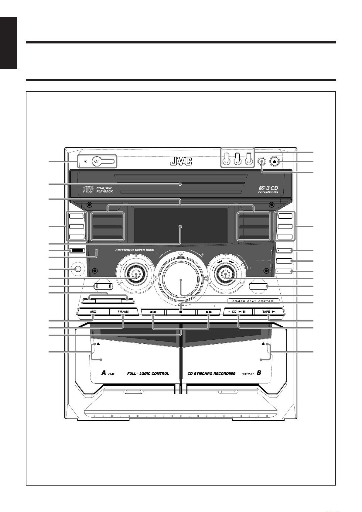
Become familiar with the buttons and controls on your unit.
Front Panel
3
Page 7

Display Window
MONO
ALL 1 DISC
REPEAT
RANDOM
PRGM
ST
GROUP TRACK
MP3
SOUND
MODE
WOOFER
TURBO
1
2 3 4
5 6
7
-
8
9
0
=
~
!
@
Continued
English
See pages in the parentheses for details.
Front Panel
1 STANDBY/ON button and STANDBY lamp (9, 24,
25)
2 Carrousel
3 Sound mode lamps (11)
4 REC START/STOP button (21)
CD REC START button (22)
DUBBING button (22)
5 Display window
6 DISPLAY button (9)
7 Remote sensor
8 PHONES jack (10)
9 SOUND MODE control (11)
p SOUND TURBO button (10)
q SUBWOOFER LEVEL +/– buttons (10)
w AUX button (9)
Pressing this button also turns on the unit.
e FM/AM button (9, 12)
Pressing this button also turns on the unit.
r TUNING +/– buttons (12)
1 / ¡ (fast rewind/fast forward) buttons (15, 20)
t Deck A cassette holder (20, 22)
Pressing the 0 EJECT portion opens the holder.
y Disc number buttons and lamps (CD1, CD2, and CD3)
(14, 15, 18, 19, 22)
Pressing one of these buttons also turns on the unit.
u 0 (Carrousel open/close) button (13 – 15, 17 – 19)
Pressing this button also turns on the unit.
i DISC CHANGE button (13, 15)
o REPEAT button (13, 15, 19)
PROGRAM (MP3 Resume on/off) button (17, 18)
RANDOM button (19)
; CLOCK/TIMER button (9, 23 – 25)
a SET button (9, 12, 18, 23 – 25)
s CANCEL/DEMO button (8, 9, 18, 24, 25)
d PRESET +/– control (12)
4/¢ (reverse search/forward search) control
(9, 15 – 19, 23 – 25)
f TAPE A/B button (20)
g VOLUME control (10)
h 7 (stop) button (13 – 15, 18 – 22)
BEEP button (11)
j TAPE 3 (play) button (9, 20, 22)
Pressing this button also turns on the unit.
k CD 6 (play/pause) button (9, 13 – 15, 18)
Pressing this button also turns on the unit.
l Deck B cassette holder (20 – 22, 24)
Pressing the EJECT 0 portion opens the holder.
Display window
1 Timer indicators
• DAILY (daily timer), SLEEP (sleep timer), REC
(recording timer), and (timer) indicators
2 GROUP indicator
3 TRACK indicator
4 Main display
• Shows the source name, frequency, etc.
5 MP3 indicator
6 Tape operation indicators
• A/B (operating deck), REC (recording), and 2 3 (tape
running) indicators
7 PRGM (program) indicator
8 SOUND MODE indicator
9 WOOFER indicator
0 TURBO indicator
- CD track number indicators
= RANDOM indicator
~ REPEAT mode indicators
• REPEAT, 1, 1 DISC, ALL DISC indicators
! Tuner operation indicators
• MONO and ST (stereo) indicators
@ Volume level, Subwoofer level and Sound Mode pattern
indicators
4
Page 8
English
MP3
1
2
6
4
3
5
w
e
7
8
9
p
q
i
o
;
a
r
t
y
u
CD
1
DISC CHANGE
DISPLAY
CD
2
CD
3
TUNING
STANDBY
RANDOM
PROGRAM
DUBBING
REC START
/ STOP
CD REC
START
SET
CLOCK
/ TIMER
CANCEL
/ DEMO
STANDBY/ON
SOUND
TURBO
TAPE A / B
REPEAT
PHONES
TUNING
ROCK
POP
CLASSIC
DANCE
HALL
STADIUM
S
O
U
N
D
M
O
D
E
V
O
L
U
M
E
EJECTEJECT
SUBWOOFER LEVEL
PRESET
BEEP
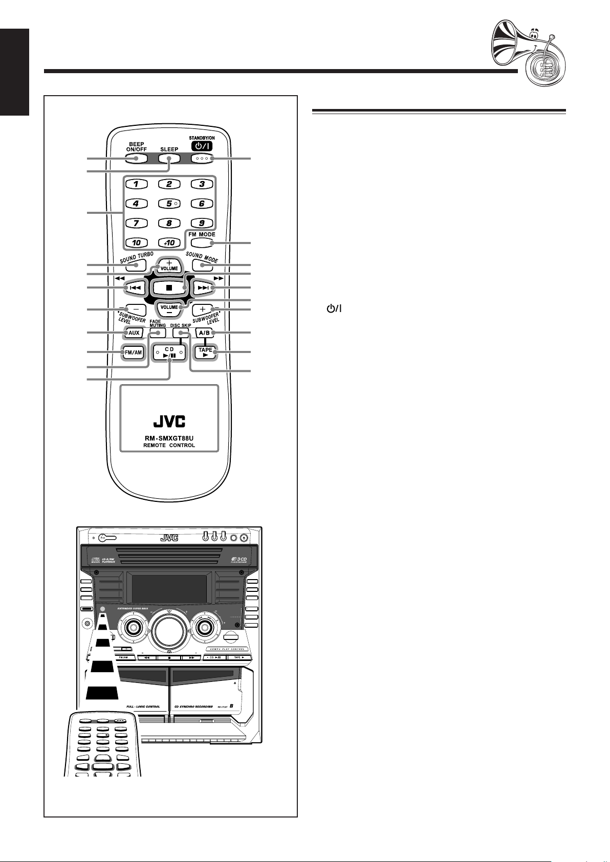
Remote Control
Remote Control
1 BEEP ON/OFF button (11)
2 SLEEP button (25)
3 Number buttons (12, 16)
4 SOUND TURBO button (10)
5 VOLUME + button (10)
6 4/1 (reverse search/fast rewind) button
(12, 15 – 17, 19, 20)
7 SUBWOOFER LEVEL – button (10)
8 AUX button (9)
Pressing this button also turns on the unit.
9 FM/AM button (9, 12)
Pressing this button also turns on the unit.
p FADE MUTING button (10)
q CD 6 (play/pause) button (9, 13 – 15, 18)
Pressing this button also turns on the unit.
w STANDBY/ON button (9)
e FM MODE button (12)
MP3 button (17)
r SOUND MODE button (11)
t 7 (stop) button (13 – 15, 18 – 22)
y ¢/¡ (forward search/fast forward) button
(12, 15 – 17, 19, 20)
u VOLUME – button (10)
i SUBWOOFER LEVEL + button (10)
o A/B button (20)
; TAPE 3 (play) button (9, 20)
Pressing this button also turns on the unit.
a DISC SKIP button (13, 15)
When using the remote control, point it at
the remote sensor on the front panel.
5
Page 9

FM [75 ]
ANTENNA
AM
Getting Started
FM [75 ]
ANTENNA
AM
Unpacking
Continued
English
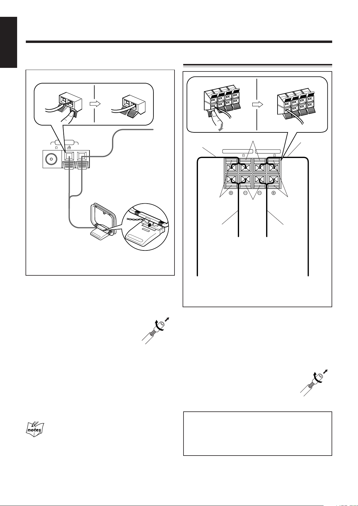
Connecting Antennas
After unpacking, check to be sure that you have all the
following items.
The number in the parentheses indicates the quantity of the
pieces supplied.
• AM loop antenna (1)
• FM antenna (1)
• Remote control (1)
• Batteries (2)
If any is missing, consult your dealer immediately.
Putting the Batteries into the Remote Control
Insert the batteries—R6P(SUM-3)/AA(15F)—into the remote
control, by matching the polarity (+ and –) on the batteries
with the + and – markings on the battery compartment.
When the remote control can no longer operate the unit,
replace both batteries at the same time.
1
FM antenna
FM antenna (supplied)
1
Attach the FM antenna to the FM [75 Ω]
coaxial terminal.
2
Extend the FM antenna.
3
Fasten it up in the position which gives you
the best reception, then fix it on the wall, etc.
About the supplied FM antenna
The FM antenna supplied with this unit can be used as temporary
measure. If reception is poor, you can connect an outdoor FM
antenna.
To connect an outdoor FM antenna
Before connecting it, disconnect the supplied FM antenna.
2
R6P(SUM-3)/AA(15F)
Outdoor FM antenna
(not supplied)
3
• DO NOT use an old battery together with a new one.
• DO NOT use different types of batteries together.
• DO NOT expose batteries to heat or flame.
• DO NOT leave the batteries in the battery
compartment when you are not going to use the
remote control for an extended period of time.
Otherwise, it will be damaged from battery leakage.
A 75 Ω antenna with coaxial type connector should be
used.
6
Page 10
English
MAIN SPEAKER
SUBWOOFER
4-8
[ ]
6
[ ]
RR
LL
-16
ANTENNA
FM 75
AM
[ ]
AM antenna
Connecting Speakers
1
AM loop antenna
(supplied)
2, 3
Vinyl-covered wire
(not supplied)
Speaker cord
(blue/black)
Blue
Speaker cord
(blue/black)
Black
Black
From right
main
speaker’s
terminals
1
2, 3
Speaker
cord
(red/black)
Red
Speaker cord
(red/black)
From right
subwoofer’s
terminals
1
Press and hold the clamp of the AM terminal
on the rear of the unit.
2
Insert the end of the AM loop antenna cord
into the terminal.
• If the AM loop antenna wire is covered
with vinyl, remove the vinyl by twisting it
as shown in the diagram.
3
Release the finger from the clamp.
4
Turn the AM loop antenna until you have the
best reception.
To connect an outdoor AM antenna
When reception is poor, connect a single vinyl-covered wire
to the AM terminal and extend it horizontally. (The AM loop
antenna must remain connected.)
For better reception of both FM and AM
• Make sure the antenna conductors do not touch any other
terminals and connecting cords.
• Keep the antennas away from metallic parts of the unit,
connecting cords, and the AC power cord.
From left
main
speaker’s
terminals
1
Press and hold the clamp of the speaker
From left
subwoofer’s
terminals
terminal on the rear of the unit.
2
Insert the end of the speaker cord into the
terminal.
Match the colors (polarity): Blue (+) to blue (+) and black
(–) to black (–); red (+) to red (+) and black (–) to black
(–).
• If the wire is covered with vinyl, remove
the vinyl by twisting it as shown in the
diagram.
3
Release the finger from the clamp.
IMPORTANT:
• Use only speakers with the same speaker impedance as
indicated by the speaker terminals on the rear of the
unit.
• DO NOT connect more than one speaker to one speaker
terminal.
7
Page 11

Connecting Other Equipment
AUX IN
CANCEL
/ DEMO
CANCEL
/ DEMO
You can connect audio equipment—used only as a playback
device.
English
NOW you are ready to plug in the unit and
other connected equipment.
• DO NOT connect any equipment while the power
is on.
• DO NOT plug in any equipment until all
connections are complete.
To connect audio equipment
Be sure that the plugs of the audio cords are color coded:
White plugs and jacks are for left audio signals, and red ones
for right audio signals.
Audio equipment
Canceling the Display Demonstration
When connecting the AC power cord into a wall outlet, the
unit automatically starts the display demonstration.
On the unit ONLY:
To cancel the display demonstration,
press CANCEL/DEMO while the display
demonstration is shown on the display.
When you press other buttons
The display demonstration stops temporarily. It will start
automatically again (if no operation is done for 2 minutes) until you
cancel it.
To start the display demonstration manually
Press and hold CANCEL/DEMO again for
more than 2 seconds.
To audio output
For playing the other equipment through this unit,
connect between the audio output jacks on the other
equipment and AUX IN jacks by using audio cords (not
supplied).
8
Page 12

Common Operations
STANDBY
STANDBY/ON
ON TIME
(Daily Timer)
DAILY
Canceled
ON TIME
(Recording Timer)
CLOCK
REC
STANDBY
STANDBY/ON
CLOCK
/ TIMER
DISPLAY
SET
SET
English
Turning On or Off the Power
To turn on the unit, press STANDBY/ON
so that the STANDBY lamp goes off.
To turn off the unit (on standby), press
STANDBY/ON again so that the
STANDBY lamp lights up.
A little power is always consumed even while the unit is on
standby.
3
Turn the 4/¢ control to
adjust the minute, then press SET.
To check the clock time
Press DISPLAY while playing any source.
• Each time you press the button, the source
indication and the clock time alternate on the
display.
To switch off the power supply completely, unplug the AC
power cord from the AC outlet.
When you unplug the AC power cord or if a power
failure occurs
The clock is reset to “– – : – –” soon, while the tuner preset stations
(see page 12) will be erased in a few days.
Setting the Clock
Before operating the unit any further, first set the clock built
in this unit. You can set the clock whether the unit is on or
off.
On the unit ONLY:
1
Press CLOCK/TIMER.
The hour digits start flashing on the display.
To adjust the clock again
If you have adjusted the clock before, you need to press
CLOCK/TIMER repeatedly until “CLOCK” is selected.
• Each time you press the button, the clock/timer setting
modes change as follows:
If there is a power failure
The clock loses the setting and is reset to “– – : – –.” You need to set
the clock again.
Selecting the Sources
To listen to the radio, press FM/AM. (See page 12.)
To play back CDs, press CD 6. (See pages 13 – 19.)
To play back tapes, press TAPE 3. (See page 20.)
To select the external equipment as the source, press AUX.
2
Turn the 4/¢ control to adjust
the hour, then press SET.
The minute digits start flashing on the
display.
• If you want to correct the hour after pressing SET,
press CANCEL/DEMO. The hour digits start
flashing again.
9
When you press the play button for a particular source (AUX,
FM/AM, CD 6, and TAPE 3), the unit turns on (and the
unit starts playing the source if it is ready—COMPU PLAY
CONTROL).
Page 13

V
O
L
U
M
E
Continued
SUBWOOFER LEVEL
WOOFER
WOOFER
TURBO
SOUND
TURBO
Adjusting the Volume
You can adjust the volume level only while the unit is turned
on.
This function only affects the playback sound, not your
recording.
Turn the VOLUME control
clockwise to increase the volume
or counterclockwise to decrease it.
• The volume level can be adjusted
in 32 steps (VOL MIN, VOL 1 —
VOL 30, and VOL MAX).
When using the remote control, press VOLUME + to
increase the volume or press VOLUME – to decrease it.
For private listening
Connect a pair of headphones to the PHONES jack. No sound
comes out of the speakers. Be sure to turn down the volume before
connecting or putting on headphones.
Reinforcing the Bass Sound
This function only affects the playback sound, not your
recording.
Press SUBWOOFER LEVEL + to
increase the subwoofer sound or
SUBWOOFER LEVEL – to
decrease it.
• The subwoofer level can be adjusted
in 3 steps (LEVEL 1 — LEVEL 3).
If you press SUBWOOFER LEVEL + to increase the level
up to LEVEL 3, “MAX LEVEL” appears on the display.
WOOFER indicator also shows the current subwoofer level.
Enjoying the Heavy Sound
English
DO NOT turn off (on standby) the unit with the
volume set to an extremely high level; otherwise, a
sudden blast of sound can damage your hearing,
speakers and/or headphones when you turn on the
unit or start playing any source next time.
REMEMBER you cannot adjust the volume level
while the unit is on standby.
To turn down the volume level temporarily
Press FADE MUTING on the remote control.
The volume level gradually decreases to
“VOL MIN.”
To restore the sound, press the button again.
You can enjoy the heavy sound by using the sound turbo. The
function boosts the low and high frequency sound.
This function only affects the playback sound, not your
recording.
Press SOUND TURBO.
The TURBO indicator lights up on the display.
• Each time you press SOUND TURBO, the
sound turbo turns on and off alternately.
TURBO indicator
When you turn off the sound turbo
The subwoofer level is set to LEVEL 1.
When the sound turbo is on
Turning the SOUND MODE control (or pressing SOUND MODE
on the remote control) cancels the sound turbo.
10
Page 14

English
SOUND
MODE
SOUND
MODE
S
O
U
N
D
M
O
D
E
D.CLUB
(Dance CLUB)
OFF
(Canceled)
HALL STADIUM ROCK
POP
CLASSIC
SOUND
MODE
WOOFER
DANCE
D.CLUB
(Dance CLUB)
OFF
(Canceled)
HALL STADIUM ROCK
POP
CLASSIC
BEEP
Selecting the Sound Modes
This function only affects the playback sound, not your
recording.
You can select one of the 6 preset sound modes (3 surround
modes and 3 SEA—Sound Effect Amplifier—modes).
To select the sound modes, turn the
SOUND MODE control until the sound
mode you want appears on the display.
SOUND MODE indicator also lights up on the display
• As you turn the control, the sound modes change as
follows:
When using the remote control, press
SOUND MODE to select the sound mode.
• Each time you press the button, the sound
modes change as follows:
When the sound mode is activated
Pressing SOUND TURBO cancels the sound mode (set to OFF).
Turning On or Off the Key-touch Tone
If you do not want the key-touch tone to beep each time you
press a button or turn a control, you can deactivate it.
• You can turn on or off the key-touch tone as follows:
–When the unit is off:
You can turn on or off the key-touch tone by operating the
unit.
–When the unit is on:
You can turn on or off the key-touch tone by operating the
unit or the remote control.
Surround modes*:
D.CLUB : Increases resonance and bass.
HALL : Adds depth and brilliance to the sound.
STADIUM: Adds clarity and spreads the sound, like in an
outdoor stadium.
SEA (Sound Effect Amplifier) modes:
ROCK : Boosts low and high frequency. Good for
acoustic music.
POP : Good for vocal music.
CLASSIC : Good for classical music.
OFF : Cancels the sound mode.
* Surround elements are added to the SEA elements to create
being-there feeling in your room.
When one of these modes is selected, the SOUND MODE
indicator lights up as
.
While one of the SEA modes (SEA elements without surround
elements) is selected, the SOUND MODE indicator lights up
as
.
• The corresponding sound mode lamp also flashes.
On the unit:
Press and hold BEEP for more than 2
seconds.
• Each time you press and hold the button, the key-touch
tone turns on and off alternately.
On the remote control:
Press BEEP ON/OFF when the unit is on.
• Each time you press the button, the key-touch
tone turns on and off alternately.
When the sound mode is set to OFF
All sound mode indicators do not flash but light up.
11
Page 15

Listening to the Radio
TUNINGTUNING
MP3
SET
PRESET
SET
PRESET
Tuning in to a Station—Auto Search
1
Press FM/AM.
The unit automatically turns on and tunes
in to the previously tuned station (either
FM or AM).
• Each time you press the button, the band alternates
between FM and AM.
2
Start searching for stations.
On the unit:
Press and hold
TUNING + or
TUNING – for more
than 1 second.
On the remote control:
Press and hold 4/1
or ¢/¡ for more than
1 second.
The unit starts searching for stations and stops when a
station of sufficient signal strength is tuned in to.
If a program is broadcast in stereo, the ST (stereo)
indicator lights up.
To stop during searching, press TUNING + or TUNING –
(or 4/1 or ¢/¡ on the remote control).
When you press TUNING + or TUNING –
(or 4/1 or ¢/¡ on the remote control) briefly
and repeatedly
The frequency changes step by step.
To change the FM reception mode
When an FM stereo broadcast is hard to receive
or noisy, press FM MODE on the remote control
so that “MONO” appears and the MONO
indicator also lights up on the display. Reception
improves.
To restore the stereo effect, press FM MODE again so that
“STEREO” appears on the display.
In this stereo mode, you can hear stereo sounds when a
program is broadcast in stereo.
On the unit ONLY:
1
Tune in to the station you want to preset (in
this example, of FM 87.50).
• See “Tuning in to a Station—Auto Search.”
2
Press SET.
3
Turn the PRESET +/– control
to select a preset number.
4
Press SET again.
The tuned station in step 1 is stored in the preset number
selected in step 3.
• Storing a new station on a used number erases the
previously stored one.
When you unplug the AC power cord or if a power
failure occurs
The preset stations will be erased in a few days. If this happens,
preset the stations again.
Tuning in to a Preset Station
1
Press FM/AM.
The unit automatically turns on and tunes
in to the previously tuned station (either
FM or AM).
• Each time you press the button, the band alternates
between FM and AM.
English
Presetting Stations
You can preset 30 FM and 15 AM stations.
In some cases, test frequencies have been already memorized
for the tuner since the factory examined the tuner preset
function before shipment. This is not a malfunction. You can
preset the stations you want into memory by following the
presetting method.
• There is a time limit in doing the following steps. If the
setting is canceled before you finish, start from step
again.
2
2
Select a preset number.
On the unit:
Turn the PRESET +/– control.
On the remote control:
Press the number buttons.
Ex.: For preset number 5, press 5.
For preset number 15,
press +10 then 5.
For preset number 20,
press +10, then 10.
For preset number 25, press +10, +10, then 5.
For preset number 30, press +10, +10, then 10.
12
Page 16

Playing Back CDs
DISC CHANGE
REPEAT
ALL DISC
GROUP
MP3
WOOFER
ALL DISC
TRACK
WOOFER
English
This unit has been designed to playback the following CDs:
• Audio CD
• CD-R (CD-Recordable)
• CD-RW (CD-ReWritable)
• MP3 disc (MP3 files recorded on a CD-R or CD-RW)*
Loading CDs
1
Press 0.
The unit automatically turns on and the
carrousel comes out.
When playing a CD-R or CD-RW
• User-edited CD-Rs (CD-Recordable) and CD-RWs
(CD-ReWritable) can be played back when they are
already “finalized.”
• Before playing back CD-Rs or CD-RWs, read their
instructions or cautions carefully.
• Some CD-Rs or CD-RWs may not be played back on this
unit because of their disc characteristics, damage or stain
on them, or if the player’s lens is dirty.
Important notices:
• In general, you will have the best performance by keeping
your CDs and the mechanism clean.
- Store CDs in their cases, and keep them in cabinets or on
shelves.
- Keep the unit’s carrousel closed when not in use.
• Continuous use of irregular shaped discs (heart-shape,
octagonal, etc.) can damage the disc rotating mechanism.
• CD-RWs may require a longer readout time since the
reflectance of CD-RWs is lower than for regular CDs.
*For MP3 discs
• This unit manages files and folders on MP3 discs as
“tracks” and “albums.”
• Playback order of the MP3 files (tracks) recorded on a disc
are determined by the writing (or encoding) application;
therefore, playback order may be different from the one
you have intended while recording the files and the folders.
• This unit show the file name—Available characters: 0–9,
A–Z, _ (underscore)—on the display when the file (tracks)
starts play; however some file names are not shown
correctly.
More about MP3 discs
• MP3 discs (either CD-R or CD-RW) require a longer readout
time. (It varies due to the complexity of the recording
configuration.)
• When making an MP3 disc, select ISO 9660 Level 1 or Level 2 as
the disc format.
• This unit does not support multisession recording.
• This unit can play MP3 files only with the following file
extensions— “.MP3,” “.Mp3,” “.mP3,” and “.mp3.”
• Non-MP3 files are ignored. If non-MP3 files are recorded together
with MP3 files, this unit will take a longer time to scan the disc. It
may also cause the unit to malfunction.
• Some MP3 discs may not be played back because of their disc
characteristics or recording conditions.
2
Place one or two discs correctly on the front
recesses of the disc tray, with its label side up.
CORRECT
• When using a CD single (8 cm), place it on the inner
recess of the disc tray.
3
If you wish to load a third disc, press
INCORRECT
DISC CHANGE on the unit or DISC
SKIP on the remote control.
The disc tray rotates by 120˚.
4
Press 0 again.
The carrousel closes.
Playing Back CDs—All Disc and One Disc
You can play all loaded CDs continuously—All Disc play, or
one selected disc—One Disc play.
All Disc play
On the unit ONLY:
1
Load CDs.
• If the current playing source is not the CD player, press
CD 6, then 7 before going to the next step.
2
Press REPEAT repeatedly so that
the ALL DISC indicator lights up
on the display.
For Audio CD:
Total Track number
For MP3 disc:
Total playing time
ALL DISC indicator
MP3 indicator
13
GROUP indicator appears when the MP3 playback mode is
the ALBUM mode. See also page 17.
Page 17

• Each time you press the button, the indication on the
REPEAT ALL DISC* REPEAT 1 DISC*
REPEAT 1*
1 DISC
ALL DISC
(initial setting)
ALL DISC
TRACK
WOOFER
ALL DISC
GROUP
MP3
WOOFER
CD
1
CD
2
CD
3
ALL DISC
GROUP
MP3
WOOFER
ALL DISC
GROUP
MP3
WOOFER
ALL DISC
MP3
WOOFER
ALL DISC
MP3
WOOFER
display changes as follows:
* See page 19.
3
Press one of the disc number
buttons (CD1, CD2 or CD3)
for the disc you want to start
to play from.
CD play starts from the first track of
the selected disc.
• Pressing CD 6 instead of the disc number buttons
starts playing back if a CD is on the tray.
Continued
• When the MP3 playback mode is the TRACK mode
(See also page 17.)
Current track title scrolls.
Current track number**
Elapsed playing time
English
For Audio CD:
Track number of the currently playing disc flashes
(Track numbers exceeding 16 are not displayed.)
Current track number Elapsed playing time
For MP3 disc:
• When the MP3 playback mode is the ALBUM mode
(See also page 17.)
Current album number
Current track title scrolls.
** In the TRACK mode, the unit manage only files (tracks) on the
MP3 disc. Folders (albums) are not recognized.
To stop during play, press 7.
• For MP3 disc, this unit can store the number of the track
that you have stopped playback. By pressing CD 6, you
can start playback again from the beginning of the same
track—Resume play (see also page 17).
To remove the disc, press 0.
CD playback sequence
When 3 CDs are loaded on the disc trays, they are played in one of
the following sequences.
• When CD1 is pressed : CD1 ] CD2 ] CD3 (then stops)
• When CD2 is pressed : CD2 ] CD3 ] CD1 (then stops)
• When CD3 is pressed : CD3 ] CD1 ] CD2 (then stops)
* When only 2 CDs are loaded, they are played in the same order,
but the disc tray without a CD is skipped.
About the disc number lamps (CD1, CD2, and CD3)
• Each disc number lamp corresponds to the disc tray of the same
number.
• The disc number lamp flashes while the corresponding CD is
being played.
• The disc number lamp goes off when the unit has detected that
there is no CD on the corresponding disc tray.
Current track number
of the current album
Elapsed playing time
14
Page 18

English
REPEAT ALL DISC* REPEAT 1 DISC*
REPEAT 1*
1 DISC
ALL DISC
(initial setting)
CD
1
CD
2
CD
3
REPEAT
1
DISC
TRACK
WOOFER
DISC CHANGE
One Disc play
When 2 or 3 CDs are loaded on the disc trays, you can
select one particular disc to be played back.
Basic CD Operations
While playing a CD, you can do the following operations.
On the unit ONLY:
1
Load CDs.
• If the current playing source is not the CD player,
press CD 6, then 7 before going to the next step.
2
Press REPEAT repeatedly so that
the 1 DISC indicator lights up on
the display.
1 DISC indicator
• Each time you press the button, the indication on the
display changes as follows:
* See page 19.
3
Press one of the disc number
buttons (CD1, CD2 or CD3)
you want to listen.
Playback stops when all tracks of the
selected disc are played once and
resumes to All Disc play.
To stop during play, press 7.
• For MP3 disc, this unit can store the number of the track
that you have stopped playback. By pressing CD 6,
you can start playback again from the beginning of the
same track—Resume play (see also page 17).
To remove the disc, press 0.
To exit from One Disc play, press REPEAT repeatedly so
that ALL DISC indicator lights up on the display.
The following operations will also cancel the One
Disc play and restore All Disc play when—
• Turning off the power,
• Ejecting the carrousel, or
• Changing the source to play.
To exchange CDs during playback of another
Press DISC CHANGE to change the CD and the
carrousel comes out.
If you change CDs during play, the current play
will not stop until all CDs you have changed are
played.
To close the carrousel, press DISC CHANGE or 0.
To skip to the another CD in the carrousel
Press DISC SKIP on the remote control.
To stop play for a moment
Press CD 6.
While pausing, “PAUSE” appears on the
display.
To resume play, press CD 6 again.
To locate a particular point in a track
During play, press and
hold 1 or ¡.
• 1: Fast reverses the disc.
• ¡: Fast forwards the disc.
When using the remote control, press
and hold 4/1 or ¢/¡.
To go to another track
For Audio CD:
Turn the 4/¢ control before or during
playback.
• 4: Goes back to the beginning of the current
or previous tracks.
• ¢: Skips to the beginning of the next or
succeeding tracks.
When using the remote control,
press 4/1 or ¢/¡.
15
If you turn the 4/¢ control (or press 4/1 or
¢/¡ on the remote control) to select a track while
playback is stopped
The selected track starts playback.
Page 19

For MP3 disc:
When the MP3 playback mode is the TRACK mode
(See also page 17.)
Turn the 4/¢ control before or during
playback.
• 4: Goes back to the beginning of the
current or previous tracks.
• ¢: Skips to the beginning of the next or
succeeding tracks.
When using the remote control,
press 4/1 or ¢/¡.
Continued
English
To go to another track directly using the number
buttons
For Audio CD:
Pressing the number button(s) before or
during play allows you to start playing
the selected track.
Ex.: For track number 5, press 5.
For track number 15, press +10, then 5.
For track number 20, press +10, then 10.
For track number 32, press +10, +10, +10, then 2.
If you turn the 4/¢ control (or press 4/1 or
¢/¡ on the remote control) to select a track while
playback is stopped
The selected track starts playback.
To go to another album on an MP3 disc
When the MP3 playback mode is the ALBUM mode
(See also page 17.)
Turn the 4/¢ control before or during
playback.
• 4: Goes back to the beginning of the first
track in the previous albums.
• ¢: Skips to the beginning of the first
track in the next or succeeding
albums.
When using the remote control,
press 4/1 or ¢/¡.
If you turn the 4/¢ control (or press 4/1 or
¢/¡ on the remote control) to select an album
while playback is stopped
The first track in the selected album starts playback.
For MP3 disc:
• When the MP3 playback mode is the TRACK mode
(See also page 17.)
Pressing the number button(s) before or
during play allows you to start playing
the selected track on the disc.
Ex.: For track number 5, press 5.
For track number 15, press +10, then 5.
For track number 20, press +10, then 10.
For track number 32, press +10, +10, +10, then 2.
For track number 123, press +10 twelve times, then 3.
• When the MP3 playback mode is the ALBUM mode
(See also page 17.)
Pressing the number button(s) before or
during play allows you to start playing
the selected track in the current album.
Ex.: For track number 5, press 5.
For track number 15, press +10, then 5.
For track number 20, press +10, then 10.
For track number 32, press +10, +10, +10, then 2.
For track number 123, press +10 twelve times, then 3.
If your entry is ignored
You have tried to enter a track number that does not exist on the disc
or in the album (for example, selecting track 14 in the album that
only has 12 tracks). Such entries are ignored.
16
Page 20

English
ALL DISC
MP3
WOOFER
PROGRAM
MP3
ALL DISC
GROUP
MP3
WOOFER
Changing the MP3 Playback Mode
Turning On or Off the Resume Play for MP3 Disc
When playing an MP3 disc, you can choose the playback
mode of the MP3 disc as follows:
• TRACK mode:
The unit recognizes only tracks (files). You can play an
MP3 disc like an Audio CD.
• ALBUM mode:
The unit recognizes tracks (files) and albums (folders) on
an MP3 disc. You can play an MP3 disc according to the
way how they are grouped.
In this mode, you can do the following operations:
• Turning the 4/¢ control (or pressing 4/1 or
¢/¡ on the remote control) allows you to skip to the
first track of the previous or next albums. (See page16.)
• Pressing the number button(s) allows you to start playing
the selected track in the current album. (See page16.)
On the remote control ONLY:
Press MP3 before or during playing an
MP3 disc.
For MP3 disc, this unit can store the number of the track that
you have stopped playback. By pressing CD 6, you can
start playback again from the beginning of the same track—
Resume play.
You can turning on and off the resume play for MP3 discs.
On the unit ONLY:
Press PROGRAM before or during playing
an MP3 disc.
• Each time you press PROGRAM, the resume play turns on
and off alternately.
The following operations will erase the memory of the
track number that you have stopped playback when—
• Pressing 0 to eject the disc.
• Pressing one of the disc number buttons to change the disc to
play.
GROUP indicator appears when the MP3 playback mode is
the ALBUM mode.
• Each time you press the button, the MP3 playback mode
changes between “ALBUM” and “TRACK” alternately.
17
Page 21

Programming the Playing Order of the Tracks
PROGRAM
ALL DISC
PRGM
TRACK
WOOFER
CD
1
CD
2
CD
3
ALL DISC
PRGM
TRACK
WOOFER
ALL DISC
PRGM
TRACK
WOOFER
SET
CANCEL
/ DEMO
—–Program Play
You can arrange the order in which the tracks play before you
start playing. You can program up to 32 tracks.
• To use Repeat play (see page 19) for Program play, press
REPEAT after starting Program play.
• This function does not work for MP3 discs.
Continued
5
Program other tracks you want.
• To program tracks from the same disc, repeat step 4.
• To program tracks from a different disc, repeat steps
and 4.
6
Press CD 6.
The tracks are played in the order you
have programmed.
English
3
On the unit ONLY:
1
Load CDs.
• If the current playing source is not the CD player, press
CD 6, then 7 before going to the next step.
2
Press PROGRAM so that
“PROGRAM” appears on the
display.
The PRGM (program) indicator also lights up on the
display.
• All Disc play is selected automatically. You cannot
select One Disc play for Program play.
• If a program has been stored in memory, the program is
called up.
3
Press one of the disc
number buttons (CD1, CD2,
and CD3) to select the disc
number you want to play.
Disc number
Program step number
To stop during play, press 7.
To exit from Program play, press PROGRAM again before
or after play so that the unit enters All Disc play. (The
program you have made is stored in memory until you turn
off the unit, eject the carrousel, or erase the program.)
• Program play is also canceled when you press 0.
To modify the program
Before playing, you can erase the last
programmed track shown on the display by
pressing CANCEL/DEMO.
• Each time you press the button, the last programmed track
is erased from the program.
To check the program during play, perform the following
procedure:
• You can check only the programmed tracks on the current
disc at one time.
1
Press CD 6 to pause Program play.
2
Turn the 4/¢ control.
The programmed tracks on the currently selected disc
appear on the display in the programmed (or reverse) order.
• If tracks on another disc have been programmed,
“PAUSE” appears on the display.
To check the programmed tracks on another disc, press
CD 6 twice, then turn the 4/¢ control.
• Pressing CD 6 again starts Program play from the track
currently shown on the display.
Track number
4
Turn the 4/¢ control to select
the track number, then press SET.
Each time you select a track and press SET,
the selected track number is added to the
track number indicator.
• You can select up to the 99th track on each
disc.
To add tracks in the program before play, simply select the
disc numbers and/or track numbers you want to add by
following steps 3 and 4 of the programming procedure.
To erase the entire program before or during play, press 7
twice.
• Turning the power off or ejecting the carrousel will also
erase the stored memory.
If you try to program a 33rd track
“FULL” will appear on the display.
If you have programmed a track from an empty tray,
or a track number that does not exist on the disc
Such program steps will be skipped.
If there is an MP3 disc on the disc tray
3
Even if you add tracks on the MP3 disc to the program in step
those tracks will be skipped.
to 5,
18
Page 22

English
REPEAT ALL DISC REPEAT 1 DISC
REPEAT 1
1 DISC*
ALL DISC*
REPEAT
CD
1
CD
2
CD
3
RANDOM
1
DISC
RANDOM
WOOFER
Playing at Random—–Random Play
Repeating Tracks or CDs—–Repeat Play
The tracks of the selected CD will play at random.
• To use Random play, you have to cancel the Program play.
On the unit ONLY:
1
Load a CD.
2
Press one of the disc number
buttons (CD1, CD2, and
CD3) for the disc you want
to play, then press 7.
3
Press RANDOM so that
“RANDOM” appears on
the display.
The RANDOM indicator also lights up on the display.
• Activating Random play cancels Repeat play or All Disc
play. (One Disc play is automatically selected.)
• For MP3 discs, activating Random play changes the
ALBUM mode to the TRACK mode.
You can have all the CDs, the program or the individual track
currently playing repeat as many times as you like.
• Repeat play and Random play cannot be used at the same
time.
On the unit ONLY:
To repeat play, press REPEAT during or
before playing.
• Each time you press the button, Repeat play
mode changes as follows, and the following
indicator lights up on the display:
REPEAT 1: Repeats one track on one CD.
REPEAT 1 DISC**: Repeats all the tracks on one CD.
REPEAT ALL DISC : Repeats all the tracks on all the CDs,
or all the tracks on the program.
* See pages 13 and 15.
** REPEAT 1 DISC is not used for Program play.
To cancel Repeat play, press REPEAT repeatedly until the
REPEAT indicator (REPEAT 1, REPEAT 1 DISC or
REPEAT ALL DISC) goes off from the display.
• Repeat play is also canceled when you press 7 or 0.
Prohibiting Disc Ejection—–Carrousel Lock
• The tracks are played automatically at random. Random
play ends when all tracks are played once.
To stop and cancel Random play, press 7.
• If you press RANDOM again during play, Random play is
canceld and the unit enters All Disc play mode.
• Random play is also canceled when you press 0.
If you turn the 4/¢ control (or press 4/1 or
¢/¡ on the remote control)
Playback skips to the next track selected randomly.
You can prohibit CD ejection from the unit and can lock the
carrousel.
• This operation is possible only while the unit is on with CD
selected as the source.
On the unit ONLY:
To prohibit disc ejection, press 0 for the carrousel while
holding 7.
“LOCKED” appears for a while, and the carrousel is locked.
If you try to eject CDs
“LOCKED” appears to inform you that the Carrousel Lock is in use.
To cancel the prohibition and unlock the carrousel, press
0 for the carrousel while holding 7.
“UN LOCKED” appears for a while, and the carrousel is
unlocked.
When you unplug the AC power cord or if a power
failure occurs
The setting of the Carrousel Lock will return to the initial setting
(not to prohibit disc ejection) in a few days.
19
Page 23

Playing Back Tapes
Playing Back a Tape
1
Press 0 EJECT for the deck you want to use.
For Deck B
For Deck A
English
To stop during play, press 7.
To operate the other deck, press TAPE A/B (or A/B on the
remote control), then TAPE 3.
To fast-forward the tape, press ¡ (or ¢/¡ on the
remote control). The tape running indicator (3) starts
flashing quickly.
To rewind the tape, press 1 (or 4/1 on the remote
control). The tape running indicator (2) starts flashing
quickly.
To remove the cassette, press 0 EJECT for deck A or
EJECT 0 for deck B.
2
Put a cassette in, with the exposed part of the
tape down and the side you want to play
facing front.
• You can play back only type I tapes.
3
Close the cassette holder gently.
If you put cassettes in both decks A and B, the last deck
which you have put a cassette into is selected.
To operate the other deck, press TAPE A/B (or A/B on
the remote control).
4
Press TAPE
The tape play starts and the tape running
indicator (3) starts flashing slowly.
33
3.
33
The use of the C-120 or thinner tape is not
recommended, since characteristic deterioration
may occur and this tape easily jams in the pinchrollers and the capstans.
When the tape plays to the end, the deck automatically stops.
20
Page 24

Recording
REC START
/ STOP
English
IMPORTANT:
• It may be unlawful to record or play back copyrighted
material without the consent of the copyright owner.
• The recording level is automatically set correctly, so it is
not affected by the VOLUME, the SUBWOOFER LEVEL,
and the SOUND MODE controls. Thus, during recording
you can adjust the sound you are actually listening to
without affecting the recording level.
• While recording, you can hear the SOUND TURBO effect
through the speakers or headphones. However, the sound is
recorded without this effect (see page 10).
• If recordings you have made have excessive noise or static,
the unit may be too close to a TV. Place the unit away from
the TV.
• You can use type I tape for recording.
To protect your recording
Cassettes have two small tabs on
the back to protect unexpected
erasure or re-recording.
To protect your recording,
remove these tabs.
To re-record on a protected tape,
cover the holes with adhesive
tape.
Recording a Tape on Deck B
On the unit ONLY:
1
Press EJECT 0 for deck B.
2
Put a recordable cassette in, with the exposed
part of the tape down and the side you want
to record facing front.
To keep the best recording and playback sound quality
If the heads, capstans, and pinch rollers of the cassette decks
become dirty, the following will occur:
• Impaired sound quality
• Discontinuous sound
• Fading
• Incomplete erasure
• Difficulty in recording
To clean the head, capstan, and pinch roller
Use a cotton swab moistened with alcohol.
Capstan
Erase head
Pinch roller
Head
To demagnetize the head
Turn off the unit, and use a head demagnetizer (available at
electronics and audio shops).
3
Close the cassette holder gently.
4
Start playing the source—FM, AM, CD
player or auxiliary equipment connected to
AUX IN jacks.
• For duplicating tapes, see “Dubbing Tapes” on page 22.
• For recording from CD, see “CD Synchronized
Recording” on page 22.
5
Press REC START/STOP.
The REC (recording) indicator lights up on
the display and recording starts.
To stop during recording, press REC START/STOP again
or 7.
To remove the cassette, press EJECT 0 for deck B.
21
Page 25

Dubbing Tapes
DUBBING
WOOFER
CD
1
CD
2
CD
3
CD REC
START
1
DISC
TRACK
WOOFER
WOOFER
On the unit ONLY:
1
Press TAPE 3, then 7.
2
Put the source cassette in deck A, and a
recordable cassette into deck B.
3
Press DUBBING.
Dubbing starts.
“DUBBING” appears, and the REC
(recording) indicator lights up on the
display.
CD Synchronized Recording
You can easily record a CD onto a tape.
• This function does not work for MP3 discs. When
recording an MP3 disc onto a tape, see “Recording a Tape
on Deck B” on page 21.
• You can also record the tracks in the order you have made
the program.
If there is a track on the MP3 disc in the program, it will be
skipped and some blank space will be recorded on the tape.
On the unit ONLY:
1
Put a recordable cassette into deck B.
2
Place a disc correctly on the recess of the disc
tray, with its label side up.
3
Press one of the disc
number buttons (CD1,
CD2, and CD3) to select the
disc, then 7.
English
To stop during dubbing, press REC START/STOP or 7.
To remove the cassettes, press 0 EJECT for deck A and
EJECT 0 for deck B.
4
Press CD REC START.
“CD REC” appears, and the REC (recording)
indicator lights up on the display.
Deck B starts recording and the CD player starts playing.
When the recording from the selected CD is done, the CD
player and deck B stop.
• When recording your program, the CD player and deck
B stop after all tracks in the program are recorded.
To stop during CD Synchronized Recording, press REC
START/STOP or 7.
To remove the cassette, press EJECT 0 for deck B.
22
Page 26

Using the Timers
DAILY
Canceled
ON TIME
(Recording Timer)
CLOCK
(See page 9.)
RECON TIME
(Daily Timer)
CD
TUNER FM
TUNER AM
TAPE
AUX
CLOCK
/ TIMER
WOOFER
CLOCK
/ TIMER
WOOFER
SET
SET
WOOFER
SET
English
There are three timers available—Daily Timer, Recording
Timer, and Sleep Timer.
Before using the timers, you need to set the clock built in the
unit. (See “Setting the Clock” on page 9.)
Using Daily Timer
With Daily Timer, you can wake to your favorite music or
radio program. You can set the timer whether the unit is on or
off.
How Daily Timer actually works
The unit automatically turns on, set the volume level to the
preset level, and starts playing the specified source when the
on-time comes (the indicator flashes while the timer is
operating). Then, when the off-time comes, the unit
automatically turns off (stands by).
Daily Timer works every day unless you cancel it.
• There is a time limit in doing the following steps. If the
setting is canceled before you finish, start from step 1 again.
• If you have made a mistake while setting timer, press
CANCEL/DEMO. (However, this does not always work. If
CANCEL/DEMO does not work, press CLOCK/TIMER
repeatedly and start from step 1 again.)
Before you start...
• When using a CD as the source to play:
—Make sure there is a CD on the currently selected
disc number tray.
• When using a tape as the source to play:
—Make sure that a tape is in the deck whose deck
indicator (A or B) is lit on the display.
• When using the external component as the source to
play:
—Set the timer equipped with the external component
at the same time.
On the unit ONLY:
1
Press CLOCK/TIMER
repeatedly until “DAILY”
appears on the display.
indicator lights up and the DAILY (daily timer)
indicator starts flashing on the display.
2
Press CLOCK/TIMER again.
“ON TIME” appears for 2 seconds, then
the unit enters on-time setting mode.
3
Set the on-time you want the unit
to turn on.
1) Turn the 4/¢ control to set the hour,
then press SET.
2) Turn the 4/¢ control to set the minute,
then press SET.
“OFF TIME” appears for 2 seconds, then
the unit enters off-time setting mode.
4
Set the off-time you want the unit
to turn off (on standby).
1) Turn the 4/¢ control to set the hour,
then press SET.
2) Turn the 4/¢ control to set the minute,
then press SET.
The unit enters source selecting mode.
5
Turn the 4/¢ control to select
the source to play, then press SET.
• Each time you turn the 4/¢ control,
the source changes as follows:
23
• Each time you press the button, the clock/timer setting
modes change as follows:
TUNER FM : tunes in to a specified preset FM station.
= go to step 6.
TUNER AM : tunes in to a specified preset AM station.
= go to step 6.
CD : plays the current disc from the first track.
= go to step 7.
TAPE : plays a tape in deck A or B.
= go to step 7.
AUX : plays an external source.
= go to step 7.
Page 27

6
DAILY
Canceled
ON TIME
(Recording Timer)
CLOCK
(See page 9.)
RECON TIME
(Daily Timer)
SET
WOOFER
SET
STANDBY
STANDBY/ON
CLOCK
/ TIMER
CANCEL
/ DEMO
SET
CLOCK
/ TIMER
CLOCK
/ TIMER
WOOFER
WOOFER
Select the preset station
number.
Turn the 4/¢ control to select the
preset station number, then press SET.
The unit enters volume setting mode.
7
Turn the 4/¢ control to set
the volume level.
• You can select the volume level from VOL
MIN, VOL 1 — VOL 30, and VOL MAX.
Continued
Using Recording Timer
With Recording Timer, you can make a tape of a radio
broadcast automatically. You can set the timer whether the
unit is on or off.
How Recording Timer actually works
The unit automatically turns on, tunes in to the specified
station, sets the volume level to “VOL MIN,” and starts
recording when the on-time comes (the indicator flashes
while the timer is operating). Then, when the off-time comes,
the unit automatically turns off (stands by).
Recording Timer works only once, but the timer setting
remains in memory until you change it.
• There is a time limit in doing the following steps. If the
setting is canceled before you finish, start from step
again.
• If you have made a mistake while setting the timer, press
CANCEL/DEMO. (However, this does not always work. If
CANCEL/DEMO does not work, press CLOCK/TIMER
repeatedly and start from step 2 again.)
2
English
8
Press SET to complete the Daily
Timer setting.
The DAILY (daily timer) indicator stops
flashing and remains lit. The settings you have done are
shown on the display in sequence for your confirmation.
9
Press STANDBY/ON to turn
off the unit (on standby) if you
have set the Daily Timer with the
unit turned on.
If the unit is turned on when the timer-on time comes
Daily Timer does not work.
To turn on or off Daily Timer after its setting is done
1
Press CLOCK/TIMER repeatedly
until “DAILY” appears on the display.
2
To turn off the Daily Timer, press
CANCEL/DEMO.
The DAILY (daily timer) indicator goes
off from the display (“OFF” appears for
a while).
The Daily Timer is canceled, but the
setting for the Daily Timer remains in
memory until you change it.
On the unit ONLY:
1
Put a recordable cassette into deck B.
2
Press CLOCK/TIMER
repeatedly until “REC”
appears on the display.
indicator lights up and the REC (recording timer)
indicator starts flashing on the display.
• Each time you press the button, the clock/timer setting
modes change as follows:
3
Press CLOCK/TIMER again.
“ON TIME” appears for 2 seconds, then
the unit enters on-time setting mode.
To turn on the Daily Timer, press SET.
The DAILY (daily timer) indicator lights
up on the display. The settings you have
done are shown on the display in
sequence for your confirmation.
24
Page 28

English
SLEEP10
OFF
(Canceled)
SLEEP20 SLEEP30 SLEEP60
SLEEP90SLEEP120
SET
SET
SET
STANDBY
STANDBY/ON
CLOCK
/ TIMER
CANCEL
/ DEMO
SET
4
5
6
7
Set the on-time you want the unit
to turn on.
1) Turn the 4/¢ control to set the
hour, then press SET.
2) Turn the 4/¢ control to set the
minute, then press SET.
“OFF TIME” appears for 2 seconds,
then the unit enters off-time setting
mode.
Set the off-time you want the unit
to turn off (on standby).
1) Turn the 4/¢ control to set the
hour, then press SET.
2) Turn the 4/¢ control to set the
minute, then press SET.
The unit enters preset station selecting
mode.
Select the preset station.
1) Turn the 4/¢ control to select the
band (“TUNER FM” or “TUNER AM”),
then press SET.
2) Turn the 4/¢ control to select a
preset channel number, then press SET.
The REC (recording timer) indicator stops
flashing and remains lit. The settings you
have done are shown on the display in
sequence for your confirmation.
Press STANDBY/ON to turn
off the unit (on standby) if
necessary.
Using Sleep Timer
With Sleep Timer, you can fall asleep to music.
You can set Sleep Timer when the unit is turned on.
How Sleep Timer actually works
The unit automatically turns off after the specified time
length passes.
On the remote control ONLY:
1
Press SLEEP.
The time length until the shut-off time appears
and the SLEEP indicator starts flashing on the
display.
• Each time you press the button, the time length changes
as follows:
2
Wait for about 3 seconds after specifying the
time length.
The SLEEP indicator stops flashing and remains lit.
To check the remaining time until the shut-off time, press
SLEEP once so that the remaining time until the shut-off time
appears for about 3 seconds.
To change the shut-off time, press SLEEP repeatedly until
the desired time length appears on the display.
To cancel the setting, press SLEEP repeatedly until “OFF”
appears on the display so that the SLEEP indicator goes off
from the display.
• Sleep Timer is also canceled when you turn off the unit.
About the recording source
If you change the source while recording, the recording source also
changes.
To turn on or off Recording Timer after its setting is
done
1
Press CLOCK/TIMER repeatedly
until “REC” appears on the display.
2
To turn off the Recording Timer,
press CANCEL/DEMO.
The REC (recording timer) indicator
goes off from the display (“OFF” appears for a while).
The Recording Timer is canceled, but the setting for the
Recording Timer remains in memory until you change it.
To turn on the Recording Timer,
press SET.
The REC (recording timer) indicator
lights up on the display. The settings you have done are
shown on the display in sequence for your confirmation.
25
Timer Priority
Since each timer can be set separately, you may wonder what
happens if the setting for these timers overlaps.
Here are some examples.
• Recording Timer has priority over Daily Timer.
If Recording Timer is set to come on while Daily Timer is
operating, Daily Timer is canceled and Recording Timer
start working.
Recording Timer
Daily Timer
• If Sleep Timer overlaps with another timer (either Daily
Timer or Recording Timer), a timer with the earlier shut-off
time has priority.
Sleep Timer
Recording Timer
When using the Recording Timer and Sleep Timer at the
same time, pay special attention to the shut-off time.
AM 6:00
canceled.
AM 6:00
7:30
7:006:30
7:30
7:006:30
canceled.
Page 29

Maintenance
To get the best performance of the unit, keep your discs, tapes, and mechanism clean.
English
Cleaning the unit
• Stains on the unit
Should be wiped off with a soft cloth. If the unit is heavily
stained, wipe it with a cloth soaked in water-diluted neutral
detergent and wrung well, then wipe clean with a dry cloth.
• Avoid the following since they may cause damage to the
unit.
- DO NOT wipe it with a hard cloth.
- DO NOT wipe it strong.
- DO NOT wipe it with thinner or benzine.
- DO NOT apply any volatile substance such as
insecticides to it.
- DO NOT allow any rubber or plastic to remain in
contact with it for a long time.
Handling discs
• Remove the disc from its case by
holding it at the edge while pressing the
center hole lightly.
• Do not touch the shiny surface of the
disc, or bend the disc.
• Put the disc back in its case after use to
prevent warping.
Handling cassette tapes
• If the tape is loose in its cassette, take up
the slack by inserting a pencil in one of
the reels and rotating.
• If the tape is loose, it may get stretched,
cut, or caught in the cassette.
• Be careful not to touch the tape surface.
• Avoid the following places to store the
tape:
— In dusty places
— In direct sunlight or heat
— In moist areas
— Near a magnet
• Be careful not to scratch the surface of
the disc when placing it back in its case.
• Avoid exposure to direct sunlight,
temperature extremes, and moisture.
To clean the disc
Wipe the disc with a soft cloth in a straight
line from center to edge.
DO NOT use any solvent—such as conventional
record cleaner, spray, thinner, or benzine—to clean
the disc.
26
Page 30

Troubleshooting
English
If you are having a problem with your unit, check this list for a possible solution before calling for service.
If you cannot solve the problem from the hints given here, or the unit has been physically damaged, call a qualified person,
such as your dealer, for service.
Symptom
Unable to cancel the display demonstration.
No sound is heard.
Hard to listen to broadcasts because of
noise.
The disc sound is discontinuous.
The carrousel does not open or close.
The disc does not play.
The MP3 disc does not play.
The readout time of the MP3 disc is too
long.
The cassette holders cannot be opened.
Impossible to record.
Operations are disabled.
Unable to operate the unit from the remote
control.
Cause
Other buttons are pressed to cancel the
display demonstration.
Connections are incorrect or loose.
• Antennas are disconnected.
• The AM loop antenna is too close to the
unit.
• The FM antenna is not properly extended
and positioned.
The disc is scratched or dirty.
• The AC power cord is not plugged in.
• The carrousel is locked.
The disc is placed upside down.
• No MP3 files are recorded on the disc.
• MP3 files do not have the file
extension—.MP3, .Mp3, .mP3, or .mp3 in
their file names.
• MP3 files are not recorded in the format
compliant with ISO 9660 Level 1 or
Level 2.
The readout time varies with the complexity
of the recording configuration.
Power supply from the AC power cord has
been cut off while the tape was running.
Small tabs on the back of the cassette are
removed.
The built-in microprocessor may
malfunction due to external electrical
interference.
• The path between the remote control and
the remote sensor on the unit is blocked.
• The batteries are exhausted.
Action
Press CANCEL/DEMO on the unit. (See
page 8.)
Check all connections and make
corrections. (See pages 6 to 8.)
• Reconnect the antennas correctly and
securely.
• Change the position and direction of the
AM loop antenna.
• Extend the FM antenna at the best
position.
Clean or replace the disc. (See page 26.)
• Plug the AC power cord.
• Unlock the carrousel. (See page 19.)
Place the disc with the label side up.
Replace the disc.
Do not use too many hierarchies and folders
when recording. Also, do not record any
other types of audio tracks together with
MP3 files. (See page 13.)
Turn on the unit.
Cover the holes with adhesive tape.
Unplug the AC power cord and then plug it
back in.
• Remove the obstruction.
• Replace the batteries.
27
Page 31

Specifications
Amplifier section—CA-MXGA8
Output Power
SUBWOOFERS : 120 W per channel, min. RMS, driven into
MAIN SPEAKERS : 60 W per channel, min. RMS, driven into
Audio input sensitivity/Impedance
Speakers/Impedance : Subwoofers : 6 Ω – 16 Ω
Tuner
FM tuning range : 87.50 MHz – 108.00 MHz
AM tuning range: 530 kHz – 1 710 kHz
CD player
CD Capacity : 3 CDs
Dynamic range : 85 dB
Signal-to-noise ratio : 85 dB
Design and specifications are
subject to change without notice.
English
6 Ω at 63 Hz with no more than 10% total
harmonic distortion.
4 Ω at 1 kHz with no more than 10% total
harmonic distortion.
(at 1 kHz, measured at MAIN SPEAKERS)
AUX : 400 mV/50 kΩ
Main speakers : 4 Ω – 8 Ω
Cassette deck
Frequency response
Normal (type I): 50 Hz – 14 000 Hz
Wow and flutter : 0.15% (WRMS)
General
Power requirement : AC 120 V , 60 Hz
Power consumption : 160 W (at operation)
18 W (on standby)
Dimensions (approx.): 270 mm x 317 mm x 453 mm (W/H/D)
Mass (approx.) : 8.8 kg
Supplied accessories
See page 6.
Speaker section—SP-MXGA8
Type : 3-way bass-reflex type
Speaker units : Subwoofer : 13.5 cm cone x1
Main Woofer : 16 cm cone x1
Tweeter : 5 cm cone x1
Power handling capacity : Subwoofer : 120 W
Main speaker : 60 W
Impedance : Subwoofer : 6 Ω
Main speaker: 4 Ω
Frequency range : Subwoofer : 30 Hz – 70 Hz
Main speaker : 70 Hz – 20 000 Hz
Sound pressure level : Subwoofer : 73 dB/W•m
Main speaker : 86 dB/W•m
Dimensions (approx.) : 290 mm x 317 mm x 336 mm (W/H/D)
Mass (approx.) : 5.5 kg each
28
Page 32

VICTOR COMPANY OF JAPAN, LIMITED
EN, SP
JVC
0503TMMMDWSAM
 Loading...