

Page 1
SERVICE MANUAL
HANDHELD PC
MP-C33DE-BU
MP-C33DE-BU
External dimensions (WHD): 217 x 24 x 153 mm (maximum dimensions excluding
projections)
Weight: Approx. 740 g (including dedicated Lithium battery pack)
For the specifications, refer to "Technische Daten" on page 119 of the Bedienungsanleutung.
1. Parts marked are critical parts for safety. To ensure safety when replacing them,
be sure to use only the designated parts.
2. Design and specifications are subject to changes without notice.
COPYRIGHT 2001 VICTOR COMPANY OF JAPAN, LTD.
NOVEMBER 2001
No. E1001
Page 2

MP-C33DE-BU
Contents
Service cautions and disassembly .......................................... 1-3
Tools and instruments required ............................................... 1-4
Cautions and requests related to servicing ............................. 1-4
Layout of main parts ............................................................... 2-1
Disassembly and assembly methods ...................................... 2-2
Exploded view, final part assembly list .................................... 3-1
Packing materials and accessories parts list ........................... 3-4
NOTE
Before accepting a unit for servicing, notify the following information to the customer.
When servicing, the data stored in the MP-C33-DE-BU will be entirely cleared and the unit will be reset to its
factory set condition.
If the customer wants to keep the previously stored data, he or she should back up the data before sending the
product for servicing. The data can be backed up by copying it onto a memory card such as a CF Card or onto the
HDD of a PC. It is also recommended that especially important data should be written down on paper.
1-2
Page 3
Service cautions and disassembly
MP-C33DE-BU
Before disassembly or assembly
1.
Perform the following operations before disassembling
the unit.
Disconnect the AC power adapter.
Remove the lithium ion battery pack.
These operations shut off the power supply to the
circuit boards and turn the unit completely off.
If these operations are not done, connectors could
be connected or disconnected while power is being
supplied to the internal circuitry and a malfunction
such as the impossibility of turning the unit on would
result.
2.
Be careful not to damage the connectors when
connecting or disconnecting wires.
Notes on disassembly and assembly
1.
Reverse the disassembly procedures for assembly.
2.
Take care of the notes provided in "Note *)".
3.
Auxiliary items to be used
Double-side adhesive tape (width 5 mm)
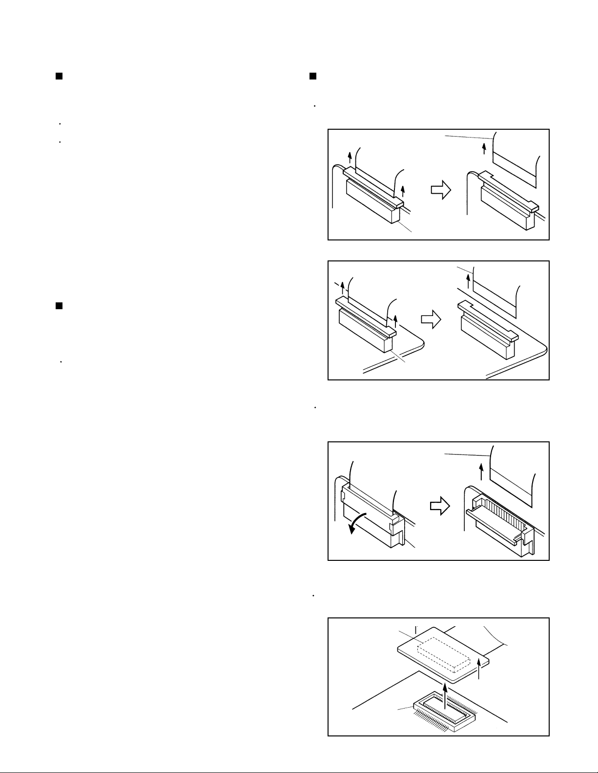
Disconnecting the connecting wires
1.
FPC connectors
Hold the connector by its two extremities and pull it
in the direction of the arrow in order to disconnect it.
Wire
Connector
Fig. 1 Connector 1
Wire
Connector
Fig. 2 Connector 2
Open the catch and pull out the wire.
The catch tends to slip out easily. Be sure to secure
it in its original position after removing the wire.
Wire
Connector
Fig. 3 Connector 3
2.
B-B connectors
Hold the circuit board by its two edges and pull it out
in order to remove it.
Connector
Connector
Fig. 4 Connector 4
1-3
Page 4

MP-C33DE-BU
Tools and instruments required
Tools and Instruments for operation check
(1) Personal computer (Windows 2000/98/95/NT4.0)
(2) PCMCIA memory card
(3) CompactFlash memory card
(4) Stylus pen
(5) External display connection cable
(6) Exclusive lithium ion battery pack
(7) AC adapter
(8) Serial cable
(9) Microsoft CD-ROM (Active Sync 3.1)
(10) USB camera (MP-UC1E)
(11) USB mouse
(12) Provider agreement
(13) Headphones
Cautions and requests related to servicing
(1)
Be sure to use the supplied tools for any servicing
operations.
(2)
Do not reuse the following parts after removal.
QAL0273-001 Touch panel
LE40739-001A Spacer
LE40739-003A Spacer
LE40776-001A Spacer
LE40800-001A Spacer
(3)
The claws or other section of the following parts may
whiten during disassembly. In this case, do not reuse
the part.
LE30863-001A Hinge cover (1)
LE30864-001A Hinge cover (2)
LE30847-003A Side fitting (L)
LE30848-003A Side fitting (R)
LE10241-006A Function panel
Tools and Instruments for Assembly
(1) LCD cable forming tool
(2) Screwdriver
(3) Grounding bands
(4) UUID writing jig
(5) Serial number and UUID correspondence table
LE30849-001A Shutter (PC)
(4)
The touch panel is thin with a thickness of only 1.15
mm and uses a glass plate (thickness 0.7 mm)
which may crack during disassembly. If this occurs,
take care against injury when handling the cracked
part.
(5)
After attaching the shutter (PC), make sure that it fits
comfortably inside the case.
(6)
Attach the microphone so that it does not float above
its correct position. (IF this occurs, the microphone
may strike the lock lever.)
(7) Attach the LCD to the front by tightening the two screws
(QYSSSPT2035Z) to a torque of between 0.06 and
0.08 N/m.
(8) Be sure to attach the grounding bands during
disassembly and assembly.
1-4
Page 5
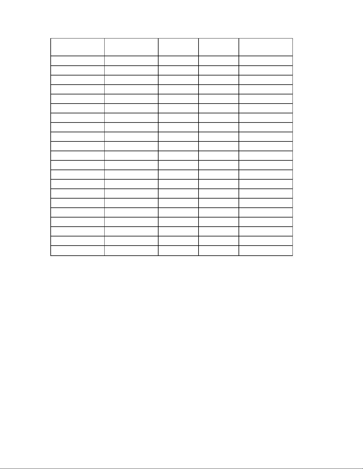
(9) The part which can not be re-used after set resolution.
MP-C33DE-BU
part number part name
LE40739-001A
LE40739-003A
LE40776-001A
LE40800-001A
LE30863-001A
LE30864-001A
LE30847-003A
LE30848-003A
LE10241-006A
LE30849-001A
LE40715-001A
LE40734-001A
QYSPSP2004N
QYSPSF2005N
QYSSSGT2040N
QYSSSPT2050N
QYSDSP2004Z
QYSPSP2003M
QYSPSPG2005Z
QYSSSPT2035Z
QYSPSGT2040N
spacer
spacer
spacer
spacer
hinge cover(1)
hinge cover(2)
side fitting(L)
side fitting(R)
function panel
shutter(pc)
foot
foot(battery)
SCREW
SCREW
SCREW
SCREW
SCREW
SCREW
SCREW
SCREW
SCREW
quantity
to use
11
2
2
1
2
1
1
1
1
1
1
4
2
3
4
2
5
3
5
2
1
unit price
Japan yen
168
168
168
168
168
168
168
168
672
168
168
168
total amount of
money
8
8
8
8
8
8
8
8
8
336
336
168
336
168
168
168
168
672
168
672
336
24
32
16
40
88
24
40
16
8
1-5
Page 6

MP-C33DE-BU
Layout of main parts
Inverter board LCD panel LCD
PEN ass'y
Hinge cover (1)
RAM board
ROM board
Battery ass'y
Wire ass'y
Touch panel
Hinge cover (2)
Microphone
Mother board
Bottom case
Exclusive lithium ion battery pack
2-1
The Mother board is shown upside down due to the configuration of the parts.
The exclusive lithium battery pack is shown in its removed condition.
Page 7

Disassembly and assembly methods
MP-C33DE-BU
The function panel and keyboard
1.
Remove the three screws S1 from the bottom of the
unit. (Fig. 1)
2.
Peel off the four feet and remove the four screws S2.
Note 1) Do not reuse the feed if they have lost their
adhesive properties. If the tip of a flat-blade
screwdriver is used for peeling them off, take
care not to scratch the bottom case. (Fig. 1)
3.
Slide the slide knob to the left and remove the screw
S3.
4.
With the slide knob positioned on the left, remove the
exclusive lithium ion battery pack. (Fig. 1)
5.
Remove the two screws S4 and then remove the
ROM cover.
Note 2) The ROM cover need not be removed except
when replacing the bottom case.
6.
Open the caps (Serial, USB, TEL). (Fig. 2)
7.
Unlock the function panel.
On the function panel lock P, release the locks from 1
to 8 as shown in the diagram on the right in order to
free the function panel.
Note 3)
8.
Remove the microphone that is pushed into the
center deep position on the backside of the function
panel.
Note 4) DO NOT lift the function panel abruptly. If it
9
Unplug the speaker wires from the connectors CN801
and CN802.
Now the function panel is completely free and
disengaged.
Note 5) If any of the claws locking the function panel
10.
Disconnect CN301 and remove the keyboard by
lifting it. (Fig. 3)
DO NOT lift the function panel abruptly after
unlocking it. If it is lifted abruptly, the microphone
and speaker wires connected to it could be
disconnected.
is lifted abruptly, the speaker wires
connected to it could be disconnected.
are damaged or whitened, do not reuse them.
Exclusive lithium ion
Exclusive lithium ion
battery pack
S1
S1
S4 S4
S4 S4
battery pack
S1
S2
S2
Foot
Foot
S2 S2
S2 S2
Slide knob
Slide knob
Rom cover
Rom cover
Foot
Foot
S3
S2
S2
S1
S1
Foot
Foot
Fig. 1
P
8
Caps
P
7
P
6
Function panel
P
5
P
Fig. 2
4
Foot
Foot
P3
Caps
P1
P2
* Main parts that can be replaced under the current
condition:
Keyboard
Function panel
ROM cover
Microphone
Screws used
S1: QYSPSP2004N
S2: QYSPSF2005N
S3: QYSSGT2040N
S4: QYSSPT2050N
CN801
CN301
Fig. 3
Key
boards
CN802
2-2
Page 8

MP-C33DE-BU
Function panel (back side) and mother/
ROM/RAM board
1.
Remove the hinge covers (L, R).
Note 6) The hinge cover provided with the boss is
(R).
(Fig. 4)
2.
Remove the microphone cap.
Note 7) Take care not to damage the claws. When
assembling, ensure that the claws are
engaged correctly.
(Fig. 4)
3.
Remove the shutter (PC) by twisting it.
(Fig. 4)
4.
Remove the left and right speakers.
Note 8) Do not reuse the spacers inserted below the
speakers.
(Fig. 4)
5.
Remove the indicator.
(Fig. 4)
6.
Remove the shutter (CF) by twisting it.
(Fig. 4)
7.
Remove PCN1 from the mother board.
(Fig. 5)
8.
Remove seven screws S7 and lift the mother board.
(Fig. 5)
9
Turn the mother board upside down, remove three
screws S6 and remove the ROM and RAM boards.
(Fig. 5)
Note 9) When attaching the mother board, push it
toward the left (toward the PC card slot).
10.
Disconnect CN803 (microphone) and CN701
(wire assembly).
(Fig. 6)
Hinge cover (R) Hinge cover (L)
Microphone cap
Function panel (back side)
Speaker
Shutter (CF)
Fig. 4
Shutter (PC)
Speaker
Indicator
* Main parts that can be replaced under the current
condition:
Mother board
Speakers
ROM board
RAM board
Hinge cover (L)
Hinge cover (R)
Microphone cap
Indicator
Shutter (PC)
Shutter (CF)
Screws Used
S5: QYSDSP2004Z
S6: QYSPSP2003M
S7: QYSPSP2005Z
S7
Fig. 5
CN803
Microphone
Fig. 6
S6
Wire ass'y
ROM
board
S6
RAM
board
CN701
2-3
Page 9

LCD front and bottom case assembly
1.
Remove the caps (Serial, USB, TEL).
(Fig. 7)
2.
Remove the battery assembly and the IrDA screen.
(Fig. 7)
3.
Remove the screws S13 and S14 and then remove
the lock lever and the cover (R).
(Fig. 7)
4.
Remove the two screws S7 and separate the LCD
assembly from the bottom case.
(Fig. 7)
5.
Ease up the side fitting (L) by sliding the side close to
the screws S8 (which are actually invisible because
they are located behind the side fitting) above the
LCD. Then, while keeping the side fitting lifted, slide it
toward the bottom of the LCD and gradually remove
the side fitting.
Note 10) Do not use the claws of the side fitting if they
are whitened.
Note 11) When attaching the side fitting for assembly,
ensure that there is no space left between it
and the LCD front.
(Fig. 8)
6.
Remove the side fitting (R) in the same way as
above. (The above notes also apply to this
procedure.)
7.
LCD front.
Note 12) Take care not to apply stress to the LCD.
(Fig. 8)
Cap
S7
IrDA
screen
Battery ass'y
Side fitting (L)
Lock lever
S13
Bottom case
Fig. 7
Cover (R)
MP-C33DE-BU
S14
Cap
Side
fitting (R)
* Main parts that can be replaced under the current
condition:
LCD front
Lock lever
Caps (Serial, USB, TEL)
Side fitting (L)
Side fitting (R)
Cover (R)
Battery assembly
Bottom case
IrDA screen
Screws Used
S7 : QYSPSP2005Z
S8 : QYSSSPT2035Z
S13: QYSSSGT2040N
S14: QYSSSPT2050N
S8
S8
LCD front
Fig. 8
2-4
Page 10

MP-C33DE-BU
Assembly of the LCD and the LCD panel
1.
To remove the hinge covers (1 & 2) and the hinge
assembly, remove the three screws S10.
Note 13) If the claws of the hinge covers (1 & 2) are
damaged or deteriorated, do not use them.
(Fig. 9)
2.
Remove the PEN assembly.
3.
Remove the screw S11 and lift the inverter board up.
Remove CN1, CN2 and CN3 to separate the inverter
board.
Note 14) Take care when handling the flexible wire of
the touch panel.
(Fig. 9)
4.
Remove the four screws S9 and lift the LCD up.
5.
Remove NC4 and separate the LCD from the wiring
assembly.
Note 15) When a new wiring assembly is used, prepare
it in advance by using the provided jig.
(Fig. 9)
6.
Remove the four spacers (2 types) attached to the
four edges on the touch panel in order to peal off the
touch pane.
Note 16) Do not use the spacers or the touch panel
again once they have been removed. The
touch panel is made from a very thin glass
sheet and is very fragile. Be careful not to
injure yourself with it.
(Fig. 9)
7.
Remove the two screws S12 and then remove the
buckle assembly.
8.
Remove the cap.
(Fig. 10)
S11
CN2
Inverter
board
Spacer
S9
CN1
CN3
Cap
S9
S10
Hinge cover (1)
Hinge cover (1)Hinge cover (1)
Hinge ass'y
LCD
Fig.9
S12 S12
Wire ass'y
S9
PEN
ass'y
CN4
S9
S10
Hinge cover (2)
* Major parts that may be replaced under this
condition.
LCD
Inverter board
Hinge assembly
Cap
LCD panel
Touch panel
Buckle assembly
Wiring assembly
PEN assembly
Hinge cover (1)
Hinge cover (2)
Screws Used
S9 : QYSDSP2004Z
S10 : QYSPSPG2005Z
S11: QYSSSGT2035M
S12: QYSSSPT2050N
LCD panel
Fig. 10
2-5
Page 11

Arranging the wire assembly and the
correct distribution of wiresmother/
ROM/RAM board assembliesassembly
Before using a brand-new wire assembly, arrange it
by using the supplied jig. (Fig. 13)
MP-C33DE-BU
Previous forming of wire assembly
Left: 9-pin wire
Distribute the wires so that the formed point comes to
the position of the hinge on the LCD panel. (Fig. 14)
Push in the wires below the plate.
Lift the LCD and take care not to
damage the wires.
The wires should not
come on or over the rib.
Right: 14-pin wire
Wire ass'y
Use jig.
Status after
forming using
the jig
Fig. 13
Push in the thin wire first, then
push in the thick wire above it.
Pass the wires between the ribs.
The 9-pin wire should be pushed
in below the 14-pin wire.
LCD panel
Formed point
Fig. 14
2-6
Page 12

MP-C33DE-BU
Mother board assembly
Always remember to take proper countermeasure against static electricity when handling the circuit boards.
Attach the two kinds of spacers (LE40777-001A and LE40777-003A) as shown in Fig. 15. Do not reuse the
spacers if their adhesive properties have been lost.
FIG. A
RAM board
The pin should be hidden completely.
Spacer (LE40777-001A)
Pin header
S6 (QYSPSP2003M) x 3.
(Back side)
FIG. B
RAM board
ROM board
Corner
alignment
Should not be
projected from
the board edge.
Mother board
5mm±1mm5mm±1mm
Spacer x 4
(LE40777003A)
Should not
be projected
from the
board edge.
Take care in handling:
Do not damage the
switch located at the
back side.
FIG. A
Mother board
Procedure for replacing a mother board...
Fig. 15
FIG. B
Alignment
SW
Polyimide tape
(width 10 mm)
Alignment
Fold the remainder on
the back side.
Note) Take care so that
the tape does not cover
the switch.
First of all, it is required to rewrite the UUID. Use the "UUID writing jig" for this purpose.
The UUID refers to the specific number assigned to each Handheld PC set. The UUID number is recorded in
the memory on the Mother board. The UUID number and the serial number are related to each other, so it is
necessary to rewrite the UUID number when replacing the Mother board. The number to be written can be
identified from the UUID Code File attached together with the "UUID writing jig".
2-7
Page 13

MP-C33DE-BU
Attaching spacers on the touch panel
Begin with attaching the right vertical spacer (LE40739-001A) on the elevated part as shown in the figure.
(The outer edge of the spacer should not exceed the outer edge of the elevation.) Next, attach the left vertical
spacer (the same part No. as above). Attach this spacer on the silver pattern of the touch panel as shown in
the magnified view. (The outer edge of the spacer should not extend beyond the outer edge of the silver
pattern. The inner edge of the silver pattern is permitted to be visible only if the visible pattern width does not
exceed 0.5 mm.) Next, attach the top and bottom horizontal spacers (LE40739-003A) in any order. Their outer
edge should not extend beyond the outer edge of the elevation. The distance between each horizontal spacer
and right vertical spacer should be less than 1 mm.
Touch panel
Align edges.
Spacer
(LE10739-003A)
< 1 mm
Spacer
(LE40739-001A)
Spacer attaching position
Spacer
Max. 0.5 mm
Silver pattern
The inner edge of the spacer should not extend
beyond that of the silver pattern.
Fig. 16
Spacer
(LE40739-003A)
Align edges.
Align edges.
Spacer
(LE40739-001A)
< 1 mm
2-8
Page 14

MP-C33DE-BU
Basic Operation Checklist
After disassembly and reassembly, check operations by referring to the following checklist.
No.
1
Appearance
2
Power On
3
Setup
4
Alarm
5
Power Off
6
Brightness control
7
Touch panel
8
Shortcut key
9
Keyboard
10
Microphone/speakers
11
Headphones
12
IrDA
13
USB
14
PC card slot
15
CF card slot
16
Modular jack
17
Serial
18
Main battery
19
Backup battery
20
Reset
21
Cold reset
Check Item Check Procedure
There should be no lacking, disengaged or scratched part or any other abnormalities.
Connect the AC adapter and press the power button.
The Power LED should light up and a screen display should appear.
Enter settings as instructed by the Setup menu.
The setup should be made as entered and the desktop (Windows Powered) should be
displayed after completion of the setup.
Set alarm by selecting "Weltuhr" > "Signal".
When the set time comes, the LED should blink and the alarm tone should be generated.
(1) Press the power button. (2) Close the LCD panel. (3) Open the Start menu and
select "Beenden".
The suspend function should be activated by any of the above operations.
Adjust brightness using "Alt + ;" and "Alt + :".
The brightness should change according to the adjustment.
Perform tapping, double tapping, dragging and image drawing (memo function).
All of the above operations should occur as a result of performing above operations.
Turn the power off and press the shortcut key.
The application assigned to the pressed key should start.
Start Pocket Word and enter the desired characters.
The characters should be displayed according to the pressed keys.
Using the Voice Recorder, record audio using the built-in microphone and play it back.
The intended audio should be recorded and played back (on both L + R channels).
Connect headphones and play the MP3 sample file "Link To The World".
The play back should occur (on both L + R channels).
Transfer (send and receive) a file between two Windows CE machines.
Data should be transferred correctly.
Connect a USB mouse and perform double-clicking and right-button clicking.
The pointer should be displayed and the intended operations should occur.
Connect the USB camera and record an image using the still capture mode.
The intended image should be displayed.
Insert a PC card in the PC card slot. The card should be recognized.
Insert a CF card (Memory) in the CF card slot. The card should be recognized
Connect to the telephone circuit and access an Internet website by means of a dial-up
connection.
The specified website page should be displayed.
Connect the PC. "Verbunden" should be displayed.
Connect to an external display. The display should show the screen.
The power management display (Stromvers...) should be as follows.
Battery drive : "Hauptbatterien" should be displayed.
During recharge : "Lädt" should be displayed and the recharge LED should light up.
No battery : "Extern" should be displayed.
After suspend, disconnect the AC adapter and main battery temporarily.
The memory should be backed up. (Reset start should not occur.)
Turn power on and press RESET. The system should reboot.
Press COLD RESET. The system should be in the initial condition when the power
button is pressed.
(Note) After completing the above checks, press the COLD RESET key to prevent consumption by the backup
battery.
2-9
Page 15

MP-C33DE-BU
VICTOR COMPANY OF JAPAN, LIMITED
IT NETWORK DIVISION, 1644, Shimotsuruma, Yamato, Kanagawa 242-8514, Japan
No. E1001
200111(S)
 Loading...