

Page 1
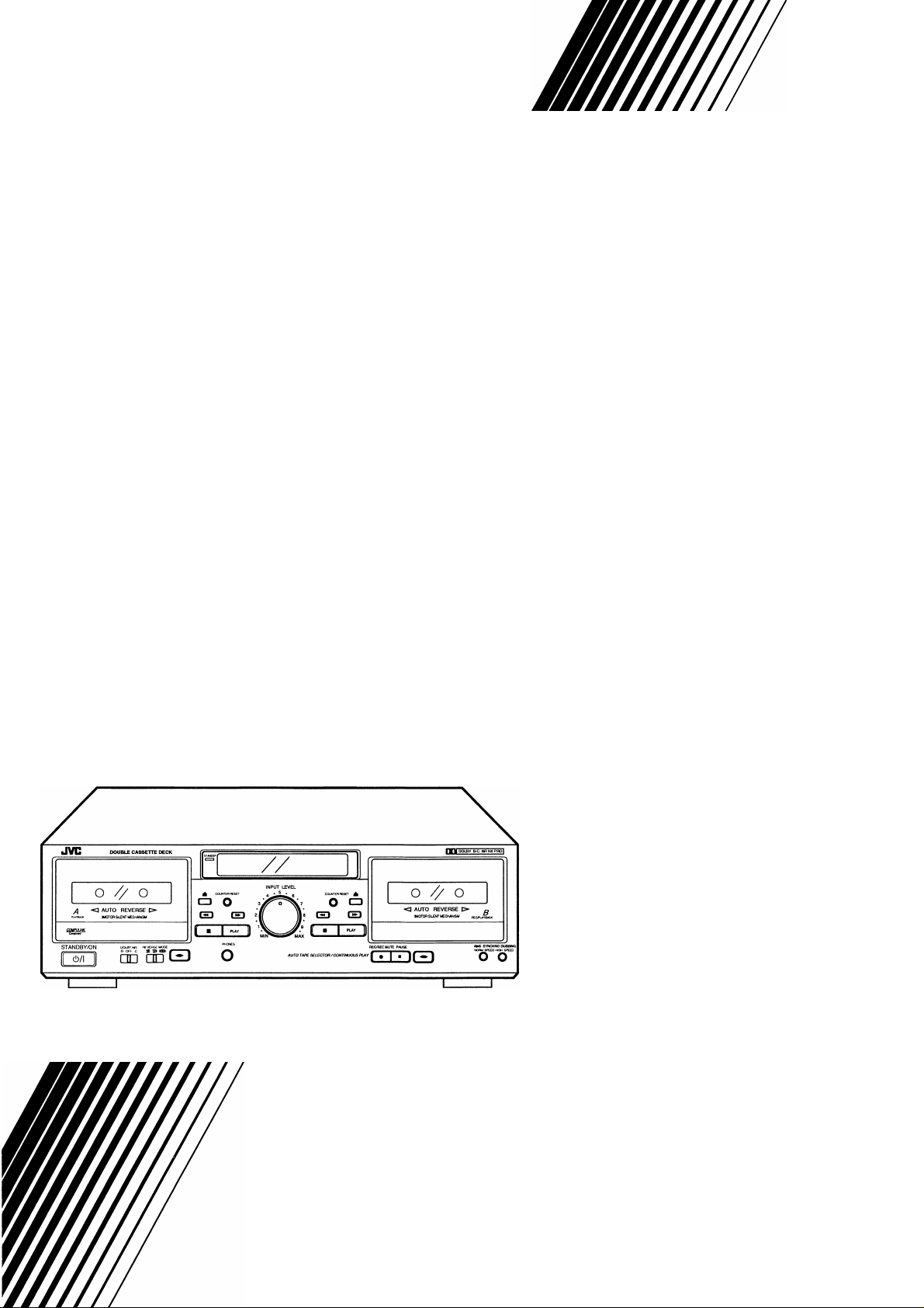
JVC
DOUBLE CASSETTE DECK
TD-W271
Component
f Itut/'
INSTRUCTIONS
LVT1089-001B
[U]
Page 2
CAUTION
RISK OF ELECTRIC SHOCK
DO NOT OPEN
CAUTION “TO REDUCE THE RISK OF ELECTRIC SHOCK
REFER SERVICING TO QUALIFIED SERVICE PERSONNEL’
WARNING:
DO NOT REMOVE COVER (OR BACK)
NO USER SERVICEABLE PARTS INSIDE
The lightning flash with arrowhead symbol, within
an equilateral triangle, is intended to alert the
user to the presence of uninsulated “dangerous
voltage” within the product’s enclosure that may
be of sufficient magnitude to constitute a risk of
electric shock to persons.
The exclamation point within an equilateral
triangle is intended to alert the user to the
presence of important operating and maintenance
(servicing) instructions in the literature
accompanying the appliance.
INTRODUCTION
Thank you for purchasing a JVC product. Read this instruction
book carefully before operating to be sure of getting optimum
performance and longer service life from the unit.
CONTENTS
Features...................................................................................1
Cautions...................................................................................1
Selecting the AC supply voltage...............................................2
Connections..............................................................................3
Cassette loading.......................................................................3
Names of parts and their functions...........................................4
Auto reverse operation
Playback...................................................................................5
Recording ................................................................................6
Сотри link control system ........................................................7
Dubbing .................................................................................. 8
Maintenance ........................................................................... 9
Troubleshooting ..................................................................... 9
Specifications
.......................................................................
.............................................................
5
10
TO REDUCE THE RISK OF FIRE OR ELECTRIC SHOCK,
DO NOT EXPOSE THIS APPLIANCE TO RAIN OR MOIS
TURE.
Please study this instruction manual carefully before starting
to operate the unit, in order to use the unit correctly. We take
no responsibility for any problems resulting from misuse of
this unit by operating this equipment other than instructed in
this manual.
Caution — Cl)/I switch!
Disconnect the mains plug to shut the power off completely.
The Cl)/I switch in any position does not disconnect the mains line.
The power can be remote controlled.
CAUTiON
• Do not block the ventilation openings or holes.
(If the ventilation openings or holes are blocked by a
newspaper or cloth, etc., the heat may not be able to
get out.)
• Do not place any naked flame sources, such as lighted
candles, on the apparatus.
• When discarding batteries, environmental problems
must be considered and local rules or laws governing
the disposal of these batteries must be followed strictly.
• Do not use this apparatus in a bathroom or places with
water. Also do not place any containers filled with water
or liquids (such as cosmetics or medicines, flower
vases, potted plants, cups, etc.) on top of this appara
tus.
Caution: Proper Ventilation
To avoide risk of electric shock and fire and to protect from
damage.
Locate the apparatus as follows:
Front: No obstructions open spacing.
Sides: No obstructions in 10 cm from the sides.
Top: No obstructions in 10 cm from the top.
Back: No obstructions in 15 cm from the back
Bottom: No obstructions, place on the level surface.
In addition, maintain the best possible air circulation as
illustrated.
CAUTION
To reduce the risk of electrical shocks, fire, etc.:
1. Do not remove screws, covers or cabinet.
2. Do not expose this appliance to rain or moisture.
-G1 -
Page 3

FEATURES
1.
Double cassette mechanism for recording/playback and
playback
Recording/playback mechanism in deck B and playback
mechanism in deck A both with reverse head system.
2.
Full logic mechanism
Dolby* HX PRO headroom extension
3.
4.
Dolby B & C noise reduction system
5.
DDRP (Dynamics Detection Recording Processor) com
patibility
The DDRP function is possible only when used with a suit
able JVC CD player.
2-color FL peak level indicator
6.
7.
Digital tape counter respectively for deck A and deck B
Synchro start (normal-/high-speed) dubbing
8.
Auto tape select mechanism (decks A and B)
9.
10.
COMPU LINK-3 compatible
Dolby noise reduction and HX Pro headroom extension
manufactured under license from Dolby Laboratories
Licensing Corporation. HX Pro originated by Bang & Olufsen.
“Dolby”, the double-D symbol □□ and “HX PRO” are trade
marks of Dolby Laboratories Licensing Corporation.
CAUTIONS
Prevention of Electric Shocks, Fire Hazards and Damage
Even when the POWER switch is set to STANDBY, a very
small current will flow. To save power and for safety when
not using the unit for an extended period of time, disconnect
the power cord from the household AC outlet.
Do not handle the power cord with wet hands.
When unplugging from the wall outlet, always grasp and pull
the plug, not the power cord.
Consult your nearest dealer when damage, disconnection, or
contact failure is found with the cord.
Do not bend the cord sharply, or pull or twist it.
Do not modify the power cord in any manner.
Do not remove screws to disassemble the unit and do not
touch anything inside the unit.
Do not insert any metallic objects into the unit.
Unplug the power cord when there is a possibility of light
ning.
10) If water gets inside the unit, unplug the power cord from the
outlet and consult your dealer.
11) Do not block the ventilation holes of the unit so that heat can
escape. Do not install the unit in a badly ventilated place.
12) Be sure to unplug the power cord from the outlet when going
out or when the unit is not in use for an extended period of
time.
COMPU LINK control system is the convenient system using
COMPU LINK-3/SYNCHRO terminals on the rear panel.
(See page 3 and 7.)
D'D-R-P
D YNAMICS DETECTION
RECORDING PROCESSOR
This product can be combinated with a DDRP (DYNAMICS
DETECTION RECORDING PROCESSOR) system (compact
disc player + cassette deck, etc.) to enable setting the opti
mum recording level automatically. Refer to these instruc
tions for details.
-1 -
Page 4
2. Installation
1) Avoid placing the unit on or adjacent to an amplifier, to pre
vent hum from being produced by some types of amplifiers.
Move the unit to a place not affected by the amplifier. Keep
the unit as far as possible from a TV set.
2) Avoid installing the unit in a location subject to ambient tem
peratures exceeding 40 °C (104 °F) (e.g. direct sunlight,
near heaters, etc.) or less than
humidity, dust or vibrations.
3) If this set is moved suddenly from a cold place (0 °C) to a
warm place, it may not function properly because of moisture
generated inside the unit. The unit will function properly
30 minutes after being moved.
3. Cleaning the cabinet
Never use benzine or thinner for cabinet cleaning as they may
damage the surface finish.
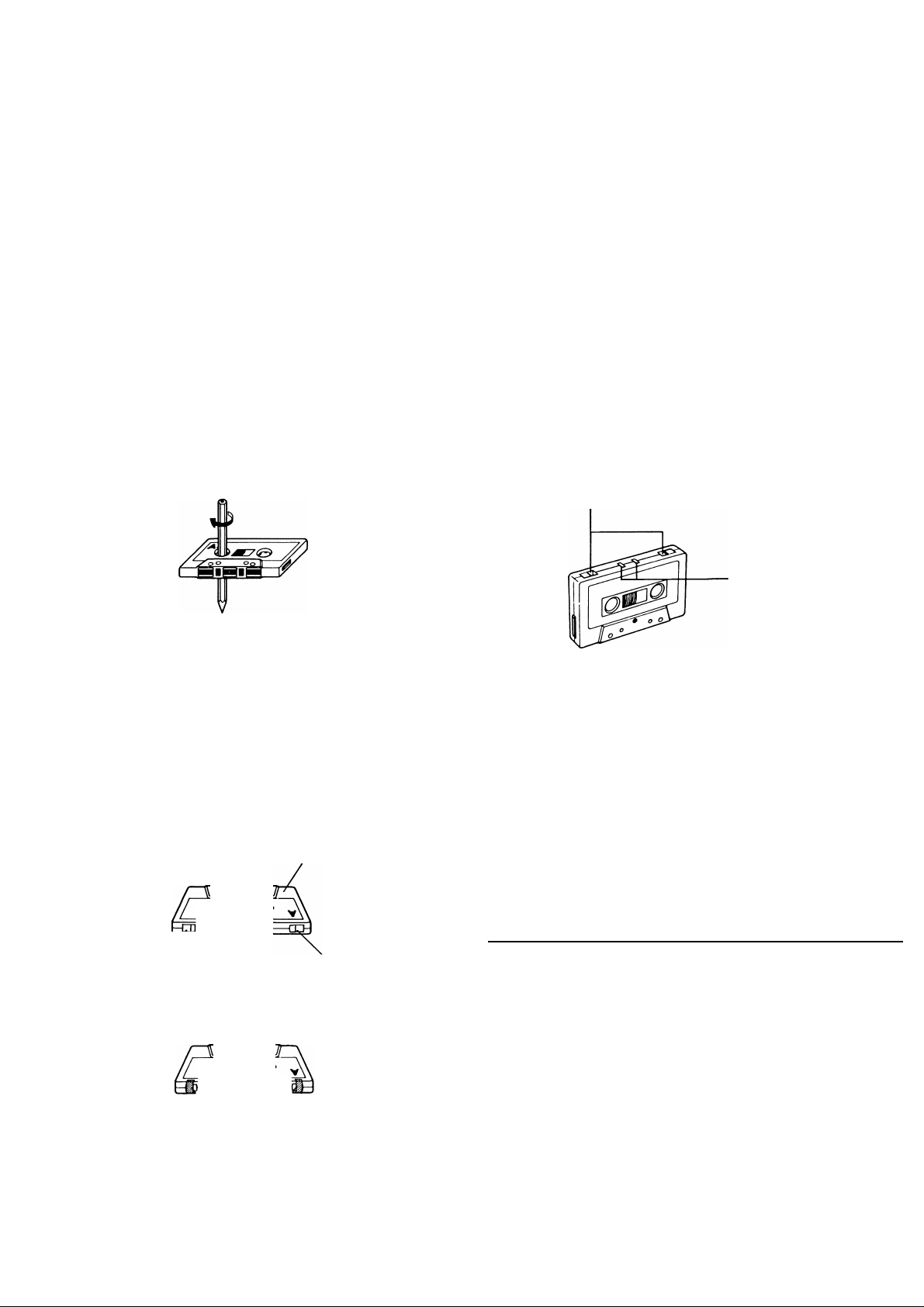
4.1)Cassette tape
Loose tape may become tangled in the tape transport
mechanism. Remove slack by winding the tape with a pen
cil.
(Fig. 2)
0 °C (32 °F), excessive
Do not store cassette tapes where there is a magnetic field
4)
(e.g. near a TV, etc.) or in a place subject to high tempera
tures or humidity.
Auto tape select mechanism (decks A and B)
5.
This deck has an Auto Tape Select mechanism which distin
guishes between different types of tape from holes in the
cassette. After the type of tape has been detected, bias and
equalization are set to be suitable for the tape.
• Cassettes with the detection holes:
Metal tape (EQ: 70ps) .........................................Type IV
Cr02 (chrome) tape (EQ: 70ps)
• Cassettes without the detection holes:
Normal tape (EQ: 120ps) .......................................Type I
Some earlier types of metal and CrQa (chrome) tapes may
not be provided with the detection holes. Avoid using such
tapes, since correct equalization characteristics cannot be
obtained. Also do not use ferrichrome tapes whose charac
teristics do not match this unit.
CrOa tape detection
holes
............................
Type II
Turn the pencil to tighten the tape.
The use of C-120 (120 minutes turn around) or thinner tape
2)
is not recommended, since characteristic deterioration may
occur.
To prevent recordings from being erased accidentally,
3)
remove the tab(s) with a screwdriver. Reseal the slots with
adhesive tape to erase and re-record after the tabs have
been broken off.
Side “A”
7 T
Tab “B” Side “B” Tab “A”
Fig. 2
Metal tape detection holes
Operations
Noise may be generated if the power is on or in standby with
the deck set to playback or recording mode. Before turning
the power on or setting to standby, confirm that the ■ (stop)
button has been pressed.
Many operations of this unit are performed under the control
2)
of a microcomputer. Use the unit only after carefully studying
the descriptions and cautions in each item. If operations are
done incorrectly, the unit may stop functioning correctly. If
this happens, turn off the power once, and then turn it on
again, so that the unit can function correctly.
SELECTING THE AC SUPPLY VOLTAGE
When this deck is used in an area where the supply voltage is
different from the preset voltage, reset the voltage selector to the
correct position.
Slide the voltage selector to the desired voltage with a screw
driver.
\ 7
Adhesive tape
Fig. 3
Cation:
Disconnect supply cord before changing the voltage.
110V 127V 230V
1
i
-2-
Page 5

CONNECTIONS
• Do not switch the power on until all the connections are com
pleted.
• Insert the plugs firmly, or poor contact will result, causing
noise.
• When the pin-plug cords are employed, always connect the
white plug to the left channel terminal. This helps to avoid
reversed connections.
• When using the Сотри Link Control System version 3, do not
connect the power cord to the SWITCHED AC OUTLET of an
amplifier or receiver.
1. Connection to a stereo amplifier
Note:
When installing the deck, be sure to install at a distance from
your amplifier. If they are stacked, noise (hum) may occur.
2. Remote cable connection for COMPU LINK
• By connecting a remote cable, COMPU LINK functions (auto
matic power on/STANDBY, automatic source selection,
synchronized recording and DDRP recording) can be per
formed. In this time the provided pin-plug cords must be also
connected.
• When making synchronized recording with a CD player, con
nect the remote cable to the COMPU LINK-3/SYNCHRO
jacks.
Notes:
1. When making synchronized recordings, only a single deck
should be connected to the amplifier.
2. If a component is not a JVC COMPU LINK component,
bypass it when making the remote cable connections.
3. This deck can be connected with an amplifier and a CD
player which have the COMPU LINK-1/SYNCHRO jacks for
COMPU LINK performance. (See page 7 for details.)
CASSETTE LOADING
1. Press the ± (eject) button to open the cassette holder.
2. Load a cassette as shown.
3. Press the cassette holder to close it. Be sure to obtain the
click sound to close the holder securely.
-3-
Page 6

NAMES OF PARTS AND THEIR FUNCTIONS
o CD/I switch (STANDBY/ON)
0 Cassette holder (deck A)
O Cassette operation buttons (deck A)
Press to wind the tape quickly from right
to left.
Press to wind the tape quickly from left to
right.
■ (stop)
PLAY
direction
Press to stop the tape.
Press to play the tape.
Press to change the direction of tape
travel.
O ~ (eject) button (deck A)
0 Power STANDBY indicator
Lights when in the power standby mode.
O COUNTER RESET button (deck A)
Press this button to set the digital counter to “00 00”.
Even if the power is set to standby mode (the STANDBY
indicator is lit up), the counter value at that time is stored in
memory.
O Indicators
© DDRP indicator
® Peak level indicator
These indicators light according to the level of the signal
being recorded or the level of the signal recorded on the
tape.
Note:
0 dB : lEC (DIN) STANDARD LEVEL (250 nWb/m)
0 VU : Signal level at 160 nWb/m
HX PRO indicator
©
Digital counter
©
The counter reading increases while the tape is running
from left to right and decreases when it is running from
right to left.
Mechanism mode indicators (Deck A)
: This lights when winding the tape
from left to right.
: This lights when winding the tape
from right to left.
PLAY
< , ^
: This lights when in the playback.
: Indicates the direction of tape travel.
® DUBBING » : “>” lights when in the normal-speed dub
bing mode.
“»” lights when in the high-speed dub
bing mode.
@ CONT : Lights when the unit is in the continuous
play mode.
® Mechanism mode indicators (Deck B)
PLAY : Lights when the unit is in the playback
and record modes.
^ : Indicates the direction of tape travel.
REC : Lights when the unit is in the record
and record-pause modes; blinks dur
ing record muting.
II : Pause indicator
: This lights when winding the tape from
left to right.
: This lights when winding the tape from
right to left.
® : Indicates reverse mode,
o COUNTER RESET button (deck B)
0 ± (eject) button (deck B)
0 Cassette holder (deck B) <D DOLBY NR switch
Set to B or C for recording using the Dolby NR system or for
playing back a tape that was recorded using the Dolby NR
system.
Set to OFF when the Dolby NR system is not used.
0 REVERSE MODE switch
Select the single side or full record/playback mode, or the
continuous play mode.
^ : For single-side recording or playback.
1 : To play or record both sides A and B.
: To play sides A and B continuously.
0 PHONES jack
Connects headphones (with an impedance of 8 Q to 1 kQ).
-4-
Page 7

<D INPUT LEVEL control 0 Cassette operation buttons (deck B)
Press to wind the tape quickly from right
to left.
Press to wind the tape quickly from left to
right.
(stop)
PLAY
• REC/
REC MUTE
II PAUSE
(direction)
0 A ► B SYNCHRO DUBBING buttons
Press to dub from deck A to deck B.
• NORM SPEED : Press to perform normal-speed dubbing.
• HIGH SPEED : Press to perform high-speed dubbing.
Press to stop the tape.
Also press to stop both decks simulta
neously during dubbing.
Press to start playback/recording.
Press the PLAY button while pressing
this button to start recording, and press
to leave an appropriate non-recorded
section. (Seepage?.)
Press to stop the tape temporarily during
recording and playback.
Press the PLAY button to release the
pause mode.
Press to change the direction of tape
travel.
PLAYBACK
AUTO REVERSE OPERATION
The auto reverse operation of this unit turns the tape transport
over to the reverse of forward direction automatically when the
tape reaches its end during recording or playback.
• Because of cassette shell construction, a tape recorded in the
forward direction should be played back in the same direction
to obtain stable sound reproduction.
• During recording, auto reverse can be activated only from the
forward to the reverse direction. For good sound quality and to
avoid accidental erasure of previously recorded material,
always start recording with the side A of the tape facing out.
Playback of deck A
Operate in the order of the numbers in the illustration.
O Turn the power on.
0 Load a prerecorded cassette with side A facing out.
o Select the side to be played back.
Side A... Forward direction (PLAY ^)
Side B... Reverse direction PLAY)
O Set the DOLBY NR switch to the same setting as when the
tape was recorded.
0
Select the REVERSE MODE switch as desired.
0
Press the PLAY button of deck A to start playback.
• When the deck contains a tape, the deck is turned on auto
matically and the tape is played back by only pressing the
PLAY button.
Playback of deck B
Perform steps
Continuous play
First set the REVERSE MODE switch to o.
Load cassette tapes in both decks and press the PLAY button of
the deck to be played first for continuous play of both decks.
• At this time, the CONT indicator lights in the multimode display.
When the tape in the deck which plays first reaches the end of
side B (in the reverse direction), it automatically switches to the
forward direction and enters the standby mode. At the same
time, the other deck starts playback. These operations con
tinue between decks A and B.
0
to 0 of the above procedure for deck B.
-5-
Page 8

• While one deck is playing back, the cassette in the other one
can be replaced. This is convenient for long-time playback of
background music.
Note:
• Use tapes recorded using the same NR mode in decks A and
B.
RECORDING
Notes:
• When the safety tabs are removed from a cassette tape, the
tape cannot be recorded even if you try. Make sure that both
tabs are still in place when performing full recording.
• When the tape is played or recorded in the reverse direction
(side B), only side B is played back or recorded and then the
tape stops automatically.
It may be unlawful to record or playback copyrighted material
without the consent of the copyright owner.
Deck B only
Operate in the order of the numbers in the illustration.
• Make sure the safety tab of the cassette has not been broken
off.
DDRP (Dynamics Detection Recording Processor) record
ing
DDRP recording is performed with suitable JVC CD players and
the recording level adjustment is performed automatically.
Since recording level adjustment is performed automatically for
different types of tape (normal, Cr02 and metal), the adjustment
of INPUT LEVEL control is not required.
Read the instruction book of your CD player carefully.
RECORDING LEVEL ADJUSTMENT
Adjust the recording level while observing the peak level indica
tor indication.
For example:
With metal tape
-30 20 15 12 10
L
Because of metal tape’s higher saturation level, it is OK that “+
2” lights occasionally.
With normal or chrome tape
6 -l-8dB
Turn the power on.
o
Load a cassette for recording.
o
Set the DOLBY NR switch as required.
o
Set the REVERSE MODE switch as desired.
o
Select the side to be recorded.
0
Press the II PAUSE button and #REC/REC MUTE button
0
(record-pause mode).
REG and II indicators light.
Adjust the recording level. (See the right column.)
o
Press to “00 00”.
0
Press the PLAY button to start recording.
0
n -30 20 15 12 10 8 6 ovu 2 0 2 4 6 + 8 dB
It is OK that “-f- 0” lights occasionally.
• When the recording level is too low, the hiss noise inherent in
the tape will be conspicuous.
• When the recording level is too high, exceeding the saturation
level, the recording will contain cracking noise and will be dis
torted.
• If “+ 4” lights too often because the recording level is too high,
the recorded sound may be distorted and seem to be breaking
up. If only “0” lights infrequently, the level is too low and the
recording may contain tape hiss.
It is best to adjust so that the maximum sound level of the
source to be recorded reaches the very limit of the saturation
level of the tape to be used.
The best level varies depending on the type of music and type
of tape so it is better to make a test recording, using FM music,
records, etc.
-6-
Page 9

AUTOMATIC RECORD MUTING (DECK B)
This facility is used to eliminate undesired sections and leave an
appropriate non-recorded section.
A. To leave non-recorded sections of about 4-5 seconds
automatically
1. When the undesired section comes during recording,
press the • REC/REC MUTE button and release it.
2. The REC indicator flashes and a non-recorded section is
made during record muting operation. About 4-5 sec
onds later, the tape automatically stops, and the unit
enters the record-pause mode.
3. Press the PLAY button to start recording again.
B. To leave non-recorded sections of more than 4-5 sec
onds
1. Keep the •REC/REC MUTE button pressed continu
ously as long as you want to make a non-recorded sec
tion. By releasing the finger from the button after the
above operation, the unit enters the record-pause mode.
2. Press the PLAY button to start recording again.
C. To leave non-recorded section of less than 4-seconds
When the undesired section comes during recording....
After the ©REC/REC MUTE button is pressed, press the
PLAY button before the unit enters the pause mode to start
recording again, or press the llPAUSE button to enter the
record-pause mode.
• The peak level indicator lights even during record muting
according to the input level which can be heard from the
speakers or headphones so that recording can be resumed at
the exact point on the tape.
ERASING
When recording on a prerecorded tape, the previous recording
is automatically erased and only the new program is recorded
on the tape.
To erase a tape without making a new recording...
Follow the section “RECORDING” but in step O, set the INPUT
LEVEL control to MIN.
DOLBY NR and DOLBY HX PRO
Dolby NR System
To reduce the hiss inherent in tape recording, use the Dolby NR
System when making recordings. When listening to a tape
recorded with the Dolby NR System, set the DOLBY NR switch
to B or C according to the system selected in the recording
mode.
Dolby HX PRO headroom extension
When a source which contains many high-frequency compo
nents is recorded, these high-frequency signals have the same
function as bias and therefore, the effective bias current
changes.
This will result in phenomena such as changes in the level of
low-frequency signal and subsequent distortion and reduction of
the high-frequency saturation level.
Dolby HX PRO headroom extension system controls the bias
current so that the effective bias is constant even when there
are fluctuations in the high-frequency components of the input
signal.
This greatly improves the high-frequency saturation level while
reducing the low-frequency signal level variations and distortion.
• The dynamic sound recorded with this system sounds the
same even when the tape is played back in a deck that does
not have Dolby HX PRO.
• This system automatically works when in recording: however,
Dolby HX PRO is not a noise reduction system.
COMPU LINK CONTROL SYSTEM
The Сотри Link Control System controls relative operations
between components automatically and facilitates various
operations.
This is a system originated and developed by JVC for facilitating
various system operations. There are two versions of this sys
tem; version 1 and 3. (For version 1 components, “COMPU
LINK-1/SYNCHRO” is marked on the rear panel. For version 3
components, “COMPU LINK-3/SYNCHRO” is marked on the
rear panel. This unit belongs to version 3.)
The version 3 system controls relative functions between this
unit and an amplifier or receiver, in addition to all of the functions
of version 1.
Automatic Power On/STANBY Function (COMPU LINK-3)
This function is available when an amplifier or receiver having a
COMPU LINK-3/SYNCHRO terminal is connected. For example,
if a deck contains a tape, the deck is turned on automatically
and the tape is played back by only pressing the PLAY button.
When the amplifier or receiver is switched STANDBY, the source
unit is automatically switched STANDBY.
Note:
The sound quality will change if the positions of the DOLBY NR
switch are different in recording and playback.
-7-
Page 10

Automatic Source Selection (COMPU LINK-1, 3)
When the provided remote cables are used for connecting this
unit to other components which have COMPU LINK-1 or
3/SYNCHRO terminals, the switch-over of all system compo
nents is possible with simple one-touch of the source selector
button of JVC’s amplifier or receiver.
By doing this, the corresponding component will start playing
automatically.
The source select button of the remote control unit or the acti
vation button of the desired component can be also used for this
purpose. When the components have been switched over, the
previous component will stop playing within five seconds.
Synchronized Recording (COMPU LINK-1, 3)
Synchronized recording refers to the process in which the deck
starts recording in synchronism with the CD player. Perform the
synchronized recording as follows:
1. Set the cassette deck to the record-pause mode in accor
dance with the recording procedures on page 6.
2. If you want the programmed recording, program the desired
tunes in any order you wish to hear.
3. Press the PLAY/PAUSE button of the CD player. By so
doing, the cassette deck is placed in the record mode and
synchronized with the CD player for recording. Synchronized
recording thus can be made possible.
DDRP (Dynamics Detection Recording Processor) record
ing
The DDRP function makes possible fully automatic recording
when used with a suitable JVC CD player. When the DDRP but
ton of a suitable JVC CD player is pressed, the recording level
is first adjusted automatically, then recording starts; it is not nec
essary to start recording by the normal procedure.
DUBBING
* Synchro dubbing
Operate in the order of the numbers in the illustration.
Notes:
• Synchronized recording or DDRP recording stops automati
cally when the CD player stops playing.
• To cancel synchronized recording or DDRP recording, press
the STOP button of the CD player or cassette deck.
• Synchronized recording does not start except when the recordpause mode is set by simultaneously pressing the
• REC/REC MUTE and II PAUSE buttons in the stop mode.
• The source is locked to the CD position during synchronized
recording or DDRP recording to avoid accidental stops or
switch-over to another component. To switch over the compo
nents, cancel synchronized recording or DDRP recording first.
• The INPUT LEVEL control does not function during DDRP
recording.
Turn the power on.
O
Load a prerecorded tape with side A facing out into deck A,
o
and press the (direction) button to select the travel
direction.
Load the blank tape with side A facing out into deck B, and
o
press the (direction) button to select the side to be
recorded.
Select the REVERSE MODE.
o
Press to “00 00”. (Deck B)
0
Press the SYNCHRO DUBBING (NORM or HIGH SPEED)
0
button to start dubbing.
Press the ■ (stop) button of deck B to stop dubbing.
When deck B stops, the dubbing mode is automatically
released.
• Synchro record muting
When deck A stops or enters any mode other than the play
back mode during dubbing, deck B enters the record mute
operation automatically and then enters the record-pause
mode.
* Before pressing the SYNCHRO DUBBING button
Confirm that deck B is in the stop mode before starting dub
bing.
Dubbing and DOLBY NR switch
During dubbing, the same NR mode selected for the playback
cassette is applied to the recording cassette, regardless of the
position of the NR switch.
Input level
Recording is performed at the same level as the playback tape
during dubbing regardless of the position of the INPUT LEVEL
control.
-8-
Page 11

Tape editing
1. Press the #REC/REC MUTE button when finished dubbing
a tune. Deck B automatically enters the record muting mode
and leaves a non-recorded section of about 4-seconds then
enters the record-paused mode.
2. Press the ■ (stop) button of deck A and search for the next
tune you want by using the ◄◄ or PLAY button. Then
stop the cassette just before the beginning of the tune.
3. Press the same SYNCHRO DUBBING button pressed
before the pause again, and dubbing will start.
Notes at dubbing
1. Normal-speed dubbing is recommended to obtain good
sound quality.
2. Television receivers placed close to the deck may cause
interference on the recorded signal when the deck is used in
the high-speed dubbing mode. If this happens, either turn off
the television receiver or use the normal-speed dubbing
mode.
Demagnetizing the heads
Magnetic objects brought close to the head or using the deck for
a long period of time, results in magnetization of the head, thus
noise occurs. When the noise is excessive, high frequencies on
the recorded tape may be erased.
Demagnetize the heads and other metal parts that come into
contact with the tape every 20-30 hours of use with a head
demagnetizer (available from your audio store).
Example: Deck B
MAINTENANCE
The importance of cleaning
When the tape is moving, magnetic powder and dust naturally
accumulate on the heads, capstan and pinch roller. When they
become too dirty.
• tone quality deteriorates.
• the output sound level drops.
• the previous sound is not erased satisfactorily.
• recordings are not satisfactory.
Because of this, clean the heads, etc. every 10 hours of use so
that optimum recordings will be made.
Cleaning the heads, pinch roller and capstan
Deck B
___________________
TROUBLESHOOTING
What appears to be trouble is not always real trouble. Make
sure first....
1. Cassette cannot be loaded.
• Is the cassette positioned correctly?
2. When PLAY button is pressed, tape does not move.
• Is the tape too loosely wound?
3. Tape runs, but no sound is heard.
• Are all connections properly and securely made?
• Is the MONITOR switch of the stereo amplifier set to the
TAPE position?
• Is the VOLUME control of the stereo amplifier set to MIN?
4. Sound quality is poor.
• Is the DOLBY NR switch set to the right position?
• Is the head section dirty?
• Is the record/playback head magnetized?
• Is the tape worn out?
5. Recording cannot be performed.
• Are the safety tabs of cassette tape broken?
• Are all connections properly and securely made?
• Is the head section dirty?
6. Previous recording is not completely erased.
• Is the erase head dirty?
7. Since tape speed is irregular, wow and flutter occur.
• Is the pinch roller or capstan dirty?
• Is the tape rewound too tight?
head
Wipe the heads, the capstan, etc. with a cotton swab with its tip
dipped in alcohol. For effective cleaning, use a cleaning kit avail
able from your audio store. After cleaning, be sure that the
cleaning fluid has completely dried before loading a cassette.
-9-
Page 12

SPECIFICATIONS
Type
Track system
Tape speed
Frequency
response
S/N ratio
Improvement of
MOL
Wow and flutter
Channel
separation
Crosstalk
Harmonic
distortion
Heads
Double cassette deck
4-track, 2-channel
4.8 cm/sec (1-7/8 inch/sec) (Normal)
9.5 cm/sec (3-3/4 inch/sec) (High)
(-20 dB recording)
Type IV tape ; 20-17,000 Hz
30-16,000 Hz (±3dB)
Type II tape ; 20-16,000 Hz
30-15,000 Hz (±3dB)
Type I tape ; 20-16,000 Hz
30-15,000 Hz (±3dB)
58 dB (S = 315 Hz, k3 = 3%,
N = A-weighted, Type IV tape)
The S/N is improved by about 15 dB at
500 Hz and by max. 20 dB at 1 kHz ~
10 kHz with Dolby C NR on and
improved by 5 dB at 1 kHz and by
10 dB at above 5 kHz with DOLBY B
NR on.
4 dB at 10 kHz with Dolby C NR on.
0.08% (WRMS), ±0.2% (DIN/IEC)
40 dB (1 kHz)
60 dB (1 kHz)
k3; 0.8% (Type IV tape, 315 Hz, 0 VU)
Deck A; METAPERM head for playback
X 1
Deck B; METAPERM head for
recording/playback, 2-gap fer
rite head for erasure; combina
tion head x 1
Motors
Fast forward/rewind
time
Input terminals
LINE IN
(x 1 circuit)
Output terminals
LINE OUT
(x 1 circuit)
PHONES X 1
Other terminals
Power
requirement
Power
consumption
Dimensions
(W X H X D)
Mass
Accessories
Design and specifications are subject to change without notice.
Electric governed DC motor for capstan
X 1
DC motor for reel x 1
DC motor for mechanism drive x 1
(For both decks A and B)
Approx. 110 sec. with C-60 cassette
Input sensitivity; 80 mV (0 VU)
Input impedance; 50 kQ
Output level; 300 mV (0 VU)
Output impedance; 5 kQ
Output level; 0.3 mW/8 Q (0 VU)
Matching impedance 8 Q-1 kQ
COMPU LINK-3/SYNCHRO x 2
AC 230/127/110 V, 50/60 Hz
With power on 17 W
With power standby 4.0 W
435 X 139 X 331 mm
4.9 kg
Pin plug cord
Remote cable
© 2003 VICTOR COMPANY OF JAPAN, LIMITED
JVC
VICTOR COMPANY OF JAPAN, LIMITED
0503HMMSANJEM
 Loading...