

Page 1
SERVICE MANUAL
YA53520077SERVICE MANUAL
LCD FLAT TELEVISION
LT-37X688/V,
LT-42X688
COPYRIGHT © 2007 Victor Company of Japan, Limited
/C
BASIC CHASSIS
FN2
Illustration of LT-37X688
1 PRECAUTION. . . . . . . . . . . . . . . . . . . . . . . . . . . . . . . . . . . . . . . . . . . . . . . . . . . . . . . . . . . . . . . . . . . . . . . . . 1-3
2 SPECIFIC SERVICE INSTRUCTIONS . . . . . . . . . . . . . . . . . . . . . . . . . . . . . . . . . . . . . . . . . . . . . . . . . . . . . . 1-7
3 DISASSEMBLY . . . . . . . . . . . . . . . . . . . . . . . . . . . . . . . . . . . . . . . . . . . . . . . . . . . . . . . . . . . . . . . . . . . . . . 1-10
4 ADJUSTMENT . . . . . . . . . . . . . . . . . . . . . . . . . . . . . . . . . . . . . . . . . . . . . . . . . . . . . . . . . . . . . . . . . . . . . . . 1-18
5 TROUBLESHOOTING . . . . . . . . . . . . . . . . . . . . . . . . . . . . . . . . . . . . . . . . . . . . . . . . . . . . . . . . . . . . . . . . . 1-31
COPYRIGHT © 2007 Victor Company of Japan, Limited
TABLE OF CONTENTS
No.YA535
2007/7
Page 2
SPECIFICATION
Items
Dimensions ( W × H × D ) 91.9 cm × 65.2 cm × 23 cm
Mass 19.5 kg (42.9 lbs) [Included stand]
Power Input AC120 V , 60 Hz
Power Consumption 210 W (Max) 250 W (Max)
TV RF System
(Analog / Digital)
Color System (Analog) NTSC
Stereo System (Analog) BTSC (Multi Channel Sound)
Teletext System (Analog) Closed caption (T1-T4 / CC1-CC4)
TV Receiving
Channels and
Frequency (Analog)
TV / CATV Total Channel 191 Channels
Intermediate Frequency
(Analog)
Color Sub Carrier Frequency (Analog) 3.58 MHz
LCD panel 37V-inch wide aspect (16:9) 42V-inch wide aspect (16:9)
Screen Size
Display Pixels Horizontal : 1920 dots × Vertical : 1080 dots (W-UXGA)
Audio Power Output 10 W + 10 W
Speaker 4.0 cm × 16.0 cm, twin oblique type × 2
Antenna Terminal
(VHF/UHF, ATSC / DIGITAL CABLE IN)
Digital input
[DIGITAL-IN 1/2]
Video / Audio input
[INPUT-3/4/5]
Audio output (Fix) 500 mV (rms), Low impedance, RCA pin jack × 2
Digital Audio Optical Output Digital SPDIF × 1
Photo Viewer / Service USB connector × 1
Remote Control Unit RM-C1450 (AA/R6 / UM-3 battery × 2)
Component Video
750p / 525p / 525i
VHF Low
VHF High
Video IF
Sound IF
Video / Audio HDMI 2-row 19pin connector × 2
[INPUT-3/4]
S-Video
[INPUT-3]
(36-1/4” x 25-3/4” x 9-1/8”) [Included stand]
91.9 cm × 60.4 cm × 10.8 cm
(36-1/4” x 23-7/8” x 4-3/8”) [TV only]
18.3 kg (40.3 lbs) [TV only]
Analog
CCIR (M)
Digital
ATSC terrestrial / Digital cable
02 ch - 06 ch : 54 MHz - 88 MHz
07 ch - 13 ch : 174 MHz - 216 MHz
14 ch - 69 ch : 470 MHz - 806 MHz
UHF
54 MHz - 804 MHz
CATV
Low Band: 02 - 06
High Band: 07 - 13
Mid Band: 14 - 22
Super Band: 23 - 36
Hyper Band: 37 - 64
Ultra Band: 65 - 94, 100 - 135
Sub Mid Band: 01, 96 - 99
45.75 MHz
41.25 MHz (4.5 MHz)
Diagonal: 94.0 cm (H: 820. cm × V: 46.0 cm)
F-type connector, 75Ω unbalanced, coaxial × 1
(Digital-input terminal is not compatible with picture signals of personal computer)
RCA pin jack × 6
1125i
Y : 1 V (p-p) (Sync signal: 0.35V(p-p), 3-value sync.), 75 Ω
Pb/Pr : ±0.35V(p-p), 75 Ω
Y : 1 V (p-p), Positive (Negative sync.), 75 Ω
Cb/Cr : 0.7V(p-p), 75 Ω
Mini-DIN 4 pin × 1
Y: 1 V (p-p), Positive (Negative sync.), 75 Ω
C: 0.286V (p-p) (Burst signal), 75 Ω
Video 1 V (p-p), Positive (Negative sync.), 75 Ω, RCA pin jack × 3
Audio 500 mV (rms), High impedance, RCA pin jack × 6
LT-37X688 LT-42X688
Contents
103.0 cm × 72.0 cm × 29.6 cm
(40-5/8” x 28-3/8” x 11-3/4”) [Included stand]
103.0 cm × 67.2 cm × 10.8 cm
(40-5/8” x 26-1/2” x 4-3/8”) [TV only]
26 kg (57.2 lbs) [Included stand]
24.1 kg (53.0 lbs) [TV only]
Diagonal: 106.7 cm (H: 93.5 cm × V: 52.8 cm)
Design & specifications are subject to change without notice.
1-2 (No.YA535)
Page 3

SECTION 1
PRECAUTION
1.1 SAFETY PRECAUTIONS
(1) The design of this product contains special hardware,
many circuits and components specially for safety
purposes. For continued protection, no changes should be
made to the original design unless authorized in writing by
the manufacturer. Replacement parts must be identical to
those used in the original circuits. Service should be
performed by qualified personnel only.
(2) Alterations of the design or circuitry of the products should
not be made. Any design alterations or additions will void
the manufacturer's warranty and will further relieve the
manufacturer of responsibility for personal injury or
property damage resulting therefrom.
(3) Many electrical and mechanical parts in the products have
special safety-related characteristics. These
characteristics are often not evident from visual inspection
nor can the protection afforded by them necessarily be
obtained by using replacement components rated for
higher voltage, wattage, etc. Replacement parts which
have these special safety characteristics are identified in
the parts list of Service manual. Electrical components
having such features are identified by shading on the
schematics and by ( ) on the parts list in Service
manual. The use of a substitute replacement which does
not have the same safety characteristics as the
recommended replacement part shown in the parts list of
Service manual may cause shock, fire, or other hazards.
(4) Don't short between the LIVE side ground and
ISOLATED (NEUTRAL) side ground or EARTH side
ground when repairing.
Some model's power circuit is partly different in the GND.
The difference of the GND is shown by the LIVE : ( ) side
GND, the ISOLATED (NEUTRAL) : ( ) side GND and
EARTH : ( ) side GND.
Don't short between the LIVE side GND and ISOLATED
(NEUTRAL) side GND or EARTH side GND and never
measure the LIVE side GND and ISOLATED (NEUTRAL)
side GND or EARTH side GND at the same time with a
measuring apparatus (oscilloscope etc.). If above note will
not be kept, a fuse or any parts will be broken.
(5) When service is required, observe the original lead dress.
Extra precaution should be given to assure correct lead
dress in the high voltage circuit area. Where a short circuit
has occurred, those components that indicate evidence of
overheating should be replaced. Always use the
manufacturer's replacement components.
(6) Isolation Check (Safety for Electrical Shock Hazard)
After re-assembling the product, always perform an
isolation check on the exposed metal parts of the cabinet
(antenna terminals, video/audio input and output terminals,
Control knobs, metal cabinet, screw heads, earphone jack,
control shafts, etc.) to be sure the product is safe to operate
without danger of electrical shock.
a) Dielectric Strength Test
The isolation between the AC primary circuit and all metal
parts exposed to the user, particularly any exposed metal
part having a return path to the chassis should withstand a
voltage of 3000V AC (r.m.s.) for a period of one second. (.
. . . Withstand a voltage of 1100V AC (r.m.s.) to an
appliance rated up to 120V, and 3000V AC (r.m.s.) to an
appliance rated 200V or more, for a period of one second.)
This method of test requires a test equipment not generally
found in the service trade.
b) Leakage Current Check
Plug the AC line cord directly into the AC outlet (do not use
a line isolation transformer during this check.). Using a
"Leakage Current Tester", measure the leakage current
from each exposed metal part of the cabinet, particularly
any exposed metal part having a return path to the chassis,
to a known good earth ground (water pipe, etc.). Any
leakage current must not exceed 0.5mA AC (r.m.s.).
However, in tropical area, this must not exceed 0.2mA AC
(r.m.s.).
Alternate Check Method
Plug the AC line cord directly into the AC outlet (do not
use a line isolation transformer during this check.). Use
an AC voltmeter having 1000Ω per volt or more
sensitivity in the following manner. Connect a 1500Ω
10W resistor paralleled by a 0.15µF AC-type capacitor
between an exposed metal part and a known good earth
ground (water pipe, etc.). Measure the AC voltage
across the resistor with the AC voltmeter. Move the
resistor connection to each exposed metal part,
particularly any exposed metal part having a return path
to the chassis, and measure the AC voltage across the
resistor. Now, reverse the plug in the AC outlet and
repeat each measurement. Any voltage measured must
not exceed 0.75V AC (r.m.s.). This corresponds to
0.5mA AC (r.m.s.).
However, in tropical area, this must not exceed 0.3V AC
(r.m.s.). This corresponds to 0.2mA AC (r.m.s.).
AC VOLTMETER
(HAVING 1000 /V,
OR MORE SENSITIVITY)
0.15 F AC-TYPE
GOOD EARTH GROUND
1500 10W
PLACE THIS PROBE
ON EACH EXPOSED
ME TAL PAR T
(No.YA535)1-3
Page 4
1.2 INSTALLATION
1.2.1 HEAT DISSIPATION
If the heat dissipation vent behind this unit is blocked, cooling
efficiency may deteriorate and temperature inside the unit will
rise. The temperature sensor that protects the unit will be
activated when internal temperature exceeds the pre-determined
level and power will be turned off automatically.Therefore,
please make sure pay attention not to block the heat dissipation
vent as well as the ventilation outlet behind the unit and ensure
that there is room for ventilation around it.
Ventilation hole
INPUT 1 INPUT 2
75
DIGITAL AUDIO
PHOTO VIEWER /
(VHF/UHF)
OPTICAL OUT
INPUT 3 INPUT 4 INPUT 5
S-VIDEO
Y
VIDEO
Y
COMPONENT
L
P
B
B
P
AUDIO
R
P
R
P
R
AUDIO OUT
VIDEO
VIDEO
COMPONENT
L
L
L
AUDIO
AUDIO
AUDIO
R
R
R
SERVICE
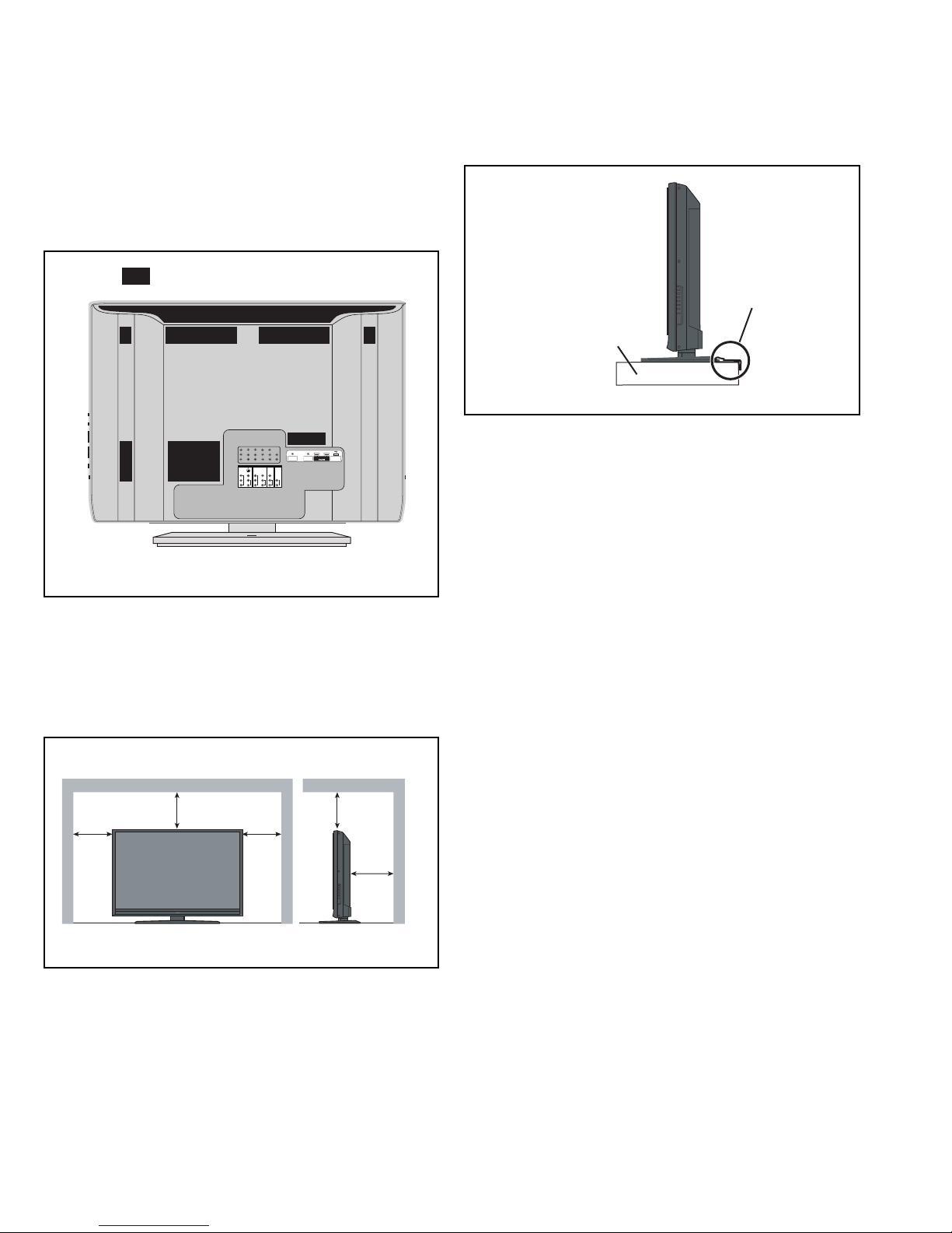
1.2.3 INSTALLATION REQUIREMENTS
To ensure safety in an emergency such as an earthquake, and
to prevent accidents, ensure that measures are taken to prevent
the TV dropping or falling over.
It fixes in a band.
TV STAND
*Diagram differs from actual appearance.
1.2.4 NOTES ON HANDLING
When taking the unit out of a packing case, do not grasp the
upper part of the unit. If you take the unit out while grasping the
upper part, the LCD PANEL may be damaged because of a
pressure. Instead of grasping the upper part, put your hands on
the lower backside or sides of the unit.
*Diagram differs from actual appearance.
1.2.2 INSTALLATION REQUIREMENTS
Ensure that the minimal distance is maintained, as specified
below, between the unit with and the surrounding walls, as well
as the floor etc.Install the unit on stable flooring or stands.Take
precautionary measures to prevent the unit from tipping in order
to protect against accidents and earthquakes.
150 mm
200 mm
POWER
*Diagram differs from actual appearance.
150 mm
200 mm
50 mm
1-4 (No.YA535)
Page 5

1.3 HANDLING LCD PANEL
1.3.1 PRECAUTIONS FOR TRANSPORTATION
When transporting the unit, pressure exerted on the internal LCD
panel due to improper handling (such as tossing and dropping)
may cause damages even when the unit is carefully packed. To
prevent accidents from occurring during transportation, pay
careful attention before delivery, such as through explaining the
handling instructions to transporters.
Ensure that the following requirements are met during
transportation, as the LCD panel of this unit is made of glass and
therefore fragile:
(1) USE A SPECIAL PACKING CASE FOR THE LCD PANEL
When transporting the LCD panel of the unit, use a special
packing case (packing materials). A special packing case
is used when a LCD panel is supplied as a service spare
part.
(2) ATTACH PROTECTION SHEET TO THE FRONT
Since the front (display part) of the panel is vulnerable,
attach the protection sheet to the front of the LCD panel
before transportation. Protection sheet is used when a LCD
panel is supplied as a service spare part.
(3) AVOID VIBRATIONS AND IMPACTS
The unit may be broken if it is toppled sideways even when
properly packed. Continuous vibration may shift the gap of
the panel, and the unit may not be able to display images
properly. Ensure that the unit is carried by at least 2
persons and pay careful attention not to exert any vibration
or impact on it.
(4) DO NOT PLACE EQUIPMENT HORIZONTALLY
Ensure that it is placed upright and not horizontally during
transportation and storage as the LCD panel is very
vulnerable to lateral impacts and may break. During
transportation, ensure that the unit is loaded along the
traveling direction of the vehicle, and avoid stacking them
on one another. For storage, ensure that they are stacked
in 2 layers or less even when placed upright.
1.3.2 OPTICAL FILTER (ON THE FRONT OF THE LCD PANEL)
(1) Avoid placing the unit under direct sunlight over a
prolonged period of time. This may cause the optical filter
to deteriorate in quality and color.
(2) Clean the filter surface by wiping it softly and lightly with a
soft and lightly fuzz cloth (such as outing flannel).
(3) Do not use solvents such as benzene or thinner to wipe the
filter surface. This may cause the filter to deteriorate in
quality or the coating on the surface to come off. When
cleaning the filter, usually use the neutral detergent diluted
with water. When cleaning the dirty filter, use water-diluted
ethanol.
(4) Since the filter surface is fragile, do not scratch or hit it with
hard materials. Be careful enough not to touch the front
surface, especially when taking the unit out of the packing
case or during transportation.
1.3.3 PRECAUTIONS FOR REPLACEMENT OF EXTERIOR
PARTS
Take note of the following when replacing exterior parts (REAR
COVER, FRONT PANEL, etc.):
(1) Do not exert pressure on the front of the LCD panel (filter
surface). It may cause irregular color.
(2) Pay careful attention not to scratch or stain the front of the
LCD panel (filter surface) with hands.
(3) When replacing exterior parts, the front (LCD panel) should
be placed facing downward. Place a mat, etc. underneath
to avoid causing scratches to the front (filter surface).
(No.YA535)1-5
Page 6
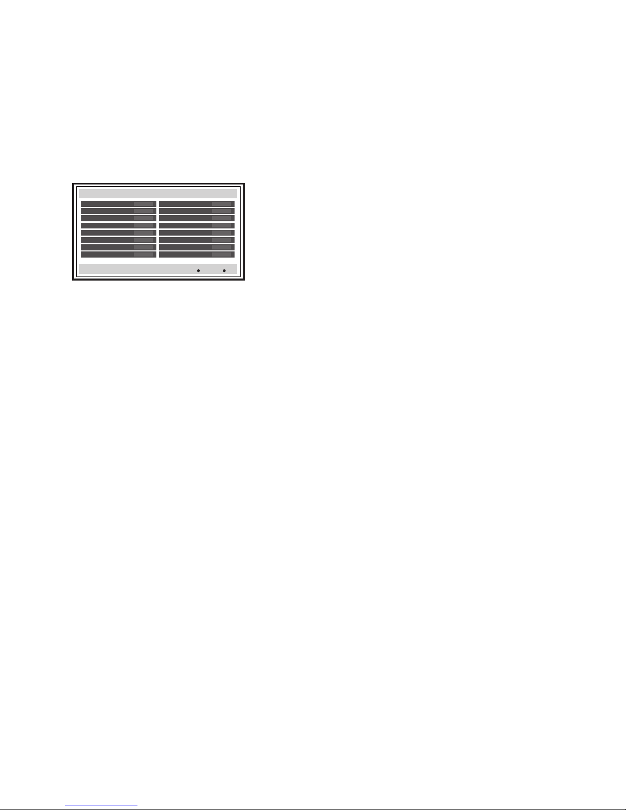
1.4 TUNER DIAGNOSTIC SCREEN
This model has a function to check the connection status of the
digital tuner. The connection status can be checked following the
below procedure.
(1) Receive digital broadcasting.
(2) Press the [MENU] key to display the user menu.
(3) Select "TUNER SETUP" from the user menu, and then
press the [OK] key.
(4) Select Tuner Diagnostic (Service Use Only) from "TUNER
SETUP", and then press the [OK] key.
(5) The below screen is displayed.
Tuner Diagnostic
Frequency 803000kHz
Modulation NTSC
Input level 0
SR -
RSE -
FO -
Ch# -2
Station
BACK
MENU
Back
Exit
Frequency
This is the in-band frequency tuned up now. If channel map is
not available, this value will be set to 0 or it may become the
frequency tuned up last time.
Modulation
This is the in-band modulation mode now. “NTSC / 64QAM /
256QAM / 8VSB”
Input level
This is the input signal power level of in-band. This value varies between 0 and 100.
SR
This is the Signal noise Ratio.
RSE
This is uncorrectable error packet count. (Read-Solomon Error
Correction Processing) When this value is not 0, it may have
influence on the quality of video or audio. However, note that
this value does not display an exact value depending on timing. If a signal is weak, this error will be occurred, but even if a
signal is too strong, it occurs.
FO
This is the out-of-band frequency tuned up now. This value
varies between 70000kHz and 130000kHz. If OOB is received
normally, frequency will be locked to a certain value (this
changes with an area or cable operators). When frequency is
continuing changing, OOB is not normally received.
Ch#
This is the channel number now.
Station
This is the channel station name now.
1-6 (No.YA535)
Page 7
SECTION 2
SERVICE MENU
1. TV-Micro Service
2. Digital Service
3. Digital Diagnostics
4. Digital Engineering Functions
TV-Micro Service
1. ADJUST
2. SELF CHECK
3. I2C STOP
LOB 0 FAN 0
AUD 0
ANA 9 DIG 9
0000 0
0
SPECIFIC SERVICE INSTRUCTIONS
2.1 SYSTEM SETTEING
Be sure to carry out the following operation at the end of
the procedure.
(1) Set to "0 minutes" using the [SLEEP] key.
(2) While "0 minutes" is displayed, press the [VIDEO] key and
[DISPLAY] key simultaneously, then enter the SERVICE
MODE.
(3 ) Press the [1] key in the SERVICE MODE SCREEN. (Fig.1)
(4) Press the [2] key in the TV-MICRO SERVICE MODE
screen. (Fig.2)
(5) The SELF CHECK MODE screen is displayed. (Fig.3)
(6) Turn off the power by pressing the [POWER] key on the
remote control unit.
SERVICE MODE SCREEN
SERVICE MENU
1. TV-Micro Service
2. Digital Service
3. Digital Diagnostics
4. Digital Engineering Functions
TV-MICRO SERVICE MODE SCREEN
Fig.1
Press [1] key
2.2 FEATURES
Built in ATSC (Advanced Television Systems Committee)
TUNER
This TV can receive both Digital broadcasting (ATSC) and
Analog broadcasting.
D.I.S.T. (Digital Image Scaling Technology)
This system uses line interpolation to double the number of
scanning lines and achieve high resolution, flicker-free picture.
Color Management
This function ensures dull colors are compensated to produce
natural hues.
Picture Management
This function makes it easier to see the dark areas when a
picture has many dark areas, and makes it easier to see the
bright areas when a picture has many bright areas.
Smart Picture
This function detects the APL (Average Picture Level) and
adjusts the contrast suitable for what you are watching.
DIGITAL VNR
This function cuts down the amount of noise in the original
picture.
MPEG Noise Reduction
This function effects the block noise removal and mosquito NR
simultaneously.
Sensor Effect
With Sensor Effect ON, a "leaf" icon will appear on your TV
screen when Smart Sensor brightness adjustment occurs.
SELF CHECK MODE(TV-MICRO)
TV-Micro Service
1. ADJUST
2. SELF CHECK
3. I2C STOP
Fig.2
LOB 0 FAN 0
AUD 0
ANA 9 DIG 9
0000 0
0
Fig.3
Press [2] key
SCREEN
(No.YA535)1-7
Page 8
2.3 TECHNICAL INFORMATION
2.3.1 LCD PANEL
This unit uses the flat type panel LCD (Liquid Crystal Display) panel that occupies as little space as possible, instead of the
conventional CRT (Cathode Ray Tube), as a display unit.
Since the unit has the two polarizing filter that are at right angles to each other, the unit adopts "normally black" mode, where light
does not pass through the polarizing filter and the screen is black when no voltage is applied to the liquid crystals.
2.3.1.1 SPECIFICATIONS
The following table shows the specifications of this unit.
Item
LT-37X688 LT-42X688
Specifications
Maximum dimensions ( W × H × D ) 87.7 cm × 51.5 cm × 5.4 cm 98.3 cm × 57.6 cm × 5.2 cm
Weight 11.0 kg 13.0 kg
Effective screen size Diagonal: 94.0 cm (H: 81.9 cm × V: 46.0 cm) Diagonal: 107.3 cm (H: 93.0 cm × V: 52.3 cm)
Aspect ratio 16 : 9
Drive device / system a-Si-TFT active matrix system
Resolution Horizontally 1920 × Vertically 1080 × RGB < W-XGA > 6220800 dots in total
Pixel pitch (pixel size)
Horizontally: 0.42675 mm, Vertically: 0.42675 mm Horizontally: 0.1615 mm, Vertically: 0.4845 mm
Displayed colour 16777216 colours 256 colours for R G and B
Brightness 500 cd/m
2
Contrast ratio 1200 : 1 1500 : 1
Response time 6 ms 6.5 ms
View angle Horizontally: 176°, Vertically: 176°
Surface polarizer Anti-Glare type Low reflective coat
Colour filter Vertical stripe
Backlight Cold cathode fluorescent lamp × 20
Power supply voltage in LCD 12 V
Power supply voltage in inverter 24 V
Panel interface system LVDS (Low Voltage Differential Signaling)
2.3.1.2 PIXEL FAULT
There are three pixel faults - bright fault, dark fault and flicker fault - that are respectively defined as follows.
BRIGHT FAULT
In this pixel fault, a cell that should not light originally is lighting on and off.
For checking this pixel fault, input ALL BLACK SCREEN and find out the cell that is lighting on and off.
DARK FAULT
In this pixel fault, a cell that should light originally is not lighting or lighting with the brightness twice as brighter as originally lighting.
For checking this pixel fault, input 100% of each R/G/B color and find out the cell that is not lighting.
FLICKER FAULT
In the pixel fault, a cell that should light originally or not light originally is flashing on and off.
For checking this pixel fault, input ALL BLACK SCREEN signal or 100% of each RGB color and find out the cell that is flashing on
and off.
1-8 (No.YA535)
Page 9
2.3.2 MAIN CPU PIN FUNCTION [IC7001
Pin Pin name I/O Function Pin Pin name I/O Function
1 VHOLD1 I Not used: Data slice for main screen closed caption 51 NC O Not used
2 HFLT1 I/O
3 NC O Not used 53 NC O Not used
4 NC O Not used 54 NC O Not used
5 DIGR0 O R [0] for OSD 55 NC O Not used
6 TB1in I AC power for timer clock 56 NC O Not used
7 REMO I Remote control 57 NC O Not used
8 BYTE I Data bus width select [L = 16bit (fixed)] 58 NC O Not used
9 CNVss I CPU programming mode select [Normal = L] 59 NC O Not used
10 DIGG0 O G [0] for OSD 60 NC O Not used
11 DIGB0 O B [0] for OSD 61 NC O Not used
12 RESET I Reset for main CPU [Reset = L] 62 HSYNC I H. sync for OSD
13 Xout O System clock osillation (crystal) : 16MHz 63 NC O Not used
14 Vss - GND 64 VSYNC I V. sync for OSD
15 Xin I System clock osillation (crystal) : 16MHz 65 NC O Not used
16 VccI I 3.3V stand-by power supply 66 NC O Not used
17 OSC1 I Clock for OSD 67 NC O Not used
18 OSC2 O Not used : Clock for OSD 68 NC O Not used
19 INT1 I Not used: AV COMPULINK control 69 NC O Not used
20 INT0 I
21 OUT1 O Ys (blanking) for OSD 71 P2.1 O Not used: Clock for Inter IC (serial) bus control
22 OUT2 O YM (transparence) for OSD 72 P2.0 I/O Not used: Data for Inter IC (serial) bus control
23 NC O Not used 73 NC O Not used
24 NC O Not used 74 NC O Not used
25 NC O Not used 75 NC O Not used
26 NC O Not used 76 NC O Not used
27 CTA2/RTS2 O Not used 77 NC O Not used
28 CLK2 O Not used 78 NC O Not used
29 RxD2 I Not used: Digital tuner control 79 NC O Not used
30 TxD2 O Not used: Digital tuner control 80 P1.0 I main CPU update
31 SDA2 I/O Not used 81 P0.7 O Not used
32 DIGR1 O R [1] for OSD 82 P0.6 O Not used
33 DIGG1 O G [1] for OSD 83 CEC_INT O Not used
34 DIGB1 O B [1] for OSD 84 WAKE O
35 TxD0 I Data transmission (serial) for external programming 85 CARD_DET I Not used
36 RxD0 O Data receive (serial) for external programming 86
37 CLK0 I Clock for external programming 87 SDA I/O Data for Inter IC (serial) bus control : memory
38 RTS0 O Busy for external programming [Operation = H] 88 SLC O Clock for Inter IC (serial) bus control : memory
39 P5.7 I Not used 89 DIGR2 O R [2] for OSD
40 P5.6 O Not used 90 DIGG2 O G [2] for OSD
41 HOLD I CPU programming mode select [Normal = H] 91 DIGB2 O B [2] for OSD
42 P5.4 O Not used 92 NC O Not used
43 P5.3 O Not used 93 KEY2 I
44 P5.2 O Not used 94 KEY1 I
45 P5.1 O Not used 95 VHOLD2 I Not used: Data slice for sub screen closed caption
46 WR O CPU programming mode select [Normal = H] 96 HLF2 I/O
47 P4.7 O
48 P4.6 I
49 P4.5 O Clock for sub(chassis) CPU communication (serial) 99 VCCE I 5V stand-by power supply
50 P4.4 O Not used 100 CVIN1 I Not used: Video(Y) for main screen closed caption
Not used: LPF for main screen closed caption video input
Interrupt request for sub(chassis) CPU [Request = L]
Data transmission for sub(chassis) CPU communication (serial)
Data receive for sub(chassis) CPU communication (serial)
: DIGITAL PWB ASS'Y]
52 NC O Not used
70 NC O Not used
Release of low power mode for sub(chassis) CPU [Release = L]
POWER_SW
97 CVIN2 I Not used: Video(Y) for sub screen closed caption
98 TVSETB I Test terminal [L Fixed]
I Power switch (mechanical) detection [On = L]
Key scan data for side control button (MENU/CH+/CH-) KEY2
Key scan data for side control button (INPUT/VOL+/VOL-) KEY1
Not used: LPF for sub screen closed caption video input
(No.YA535)1-9
Page 10

SECTION 3
DISASSEMBLY
3.1 CAUTION AT DISASSEMBLY
• Be sure to perform the SYSTEM SETTEING, at the end of the procedure.
• Make sure that the power cord is disconnected from the outlet.
• Pay special attention not to break or damage the parts.
• Make sure that there is no bent or stain on the connectors before inserting, and firmly insert the connectors.
REFERENCE:
When removing each board, remove the connector if necessary. The operation is easier if you write down the connection points
(connector numbers) of the connector. For connection of each board, refer to the "WIRING DIAGRAM" of the Standard Circuit
Diagram.
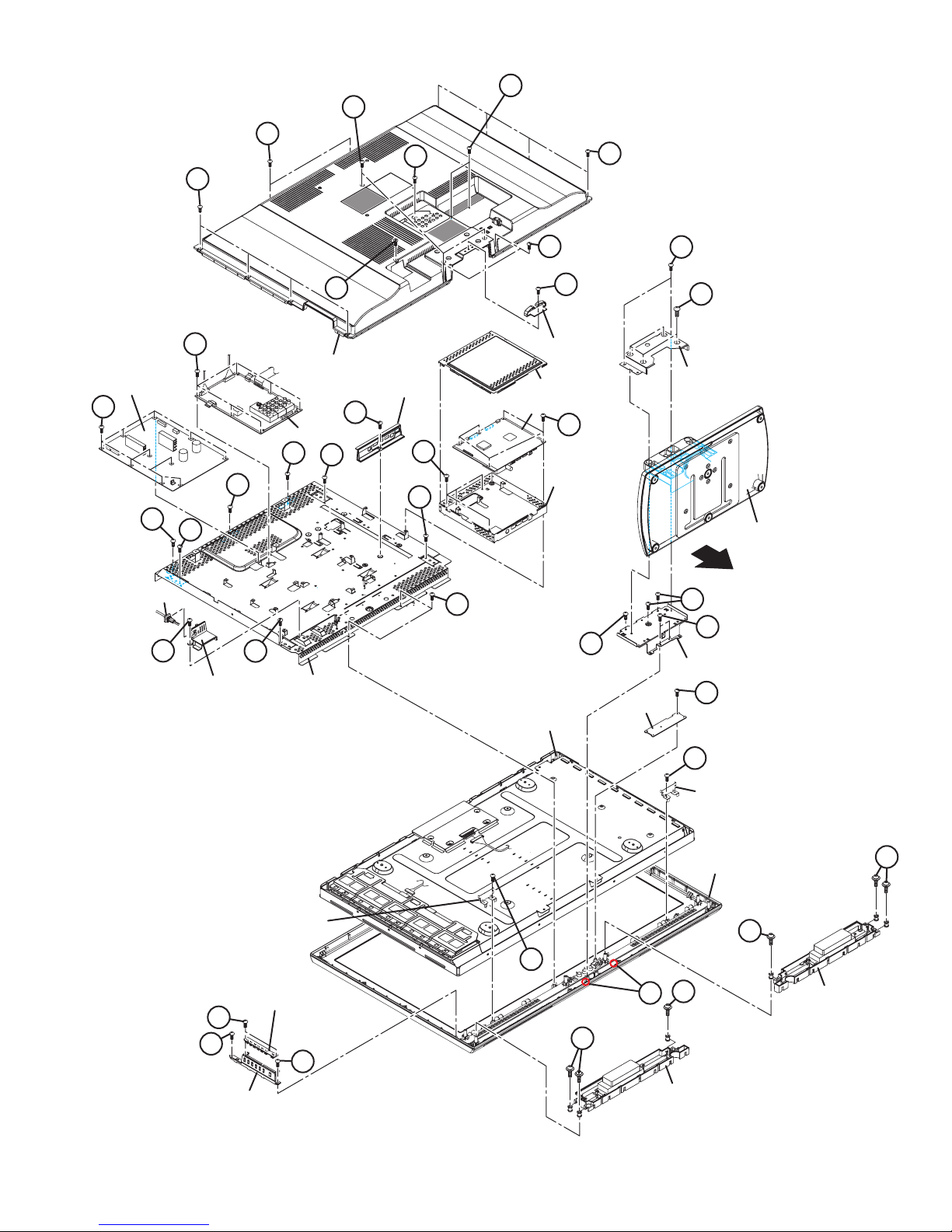
3.2 DISASSEMBLY PROCEDURE [LT-37X688/V]
3.2.1 REMOVING THE REAR COVER (Fig.3-1)
(1) Remove the 1 screw [A].
(2) Remove the CORD CLAMP.
(3) Remove the 10 screws [B], the 3 screws [C], and the 7
screws [D].
(4) Remove the REAR COVER.
3.2.6 REMOVING THE SW PWB (Fig.3-1)
• Remove the REAR COVER.
(1) Remove the 2 screws [M].
(2) Remove the SW PWB.
(3) Remove the 2 screws [N].
(4) Remove the CONTROL KNOB.
3.2.2 REMOVING THE STAND ASS’Y (Fig.3-1)
• Remove the CORD CLAMP
(1) Remove the 4 screws [E].
(2) Remove the STAND ASS’Y in the direction of the arrow.
3.2.3 REMOVING THE POWER PWB (Fig.3-1)
• Remove the REAR COVER.
(1) Remove the 1 screw [F].
(2) Remove the POWER CORD HOLDER.
(3) Remove the POWER CORD.
(4) Remove the 10 screws [G].
(5) Remove the POWER PWB.
3.2.4 REMOVING THE ANALOG PWB (Fig.3-1)
• Remove the REAR COVER.
(1) Remove the 6 screws [H].
(2) Remove the ANALOG PWB.
3.2.5 REMOVING THE DIGITAL PWB (Fig.3-1)
• Remove the REAR COVER.
(1) Remove the 1 screw [J].
(2) Remove the DIGITAL BASE.
(3) Remove the SHIELD COVER.
(4) Remove the 5 screws [K].
(5) Remove the DIGITAL PWB.
(6) Remove the 4 screws [L].
(7) Remove the SHIELD BASE.
CAUTION:
Make sure to perform the "SYSTEM SETTEING", when
DIGITAL PWB is replaced.
3.2.7 REMOVING THE LED PWB (Fig.3-1)
• Remove the REAR COVER.
• Remove the STAND ASS’Y.
(1) Remove the 2 screw [P].
(2) Remove the STAND BASE COVER.
(3) Remove the 2 screws [Q] and 3 screws [R].
(4) Remove the STAND BASE SUPPORT.
(5) Remove the 2 hooks [a] and 1 screw [S].
(6) Remove the LED PWB.
3.2.8 REMOVING THE SPEAKER (Fig.3-1)
• Remove the REAR COVER.
• Remove the STAND ASS’Y.
• Remove the STAND BASE COVER.
• Remove the STAND BASE SUPPORT.
(1) Remove the 3 screws [T].
(2) Remove the SPEKAER.
(3) Follow the same steps when removing the other hand
SPEAKER.
NOTE
When the SPEAKER is decomposed, the performance cannot
be kept.
3.2.9 REMOVING THE LCD PANEL UNIT (Fig.3-1)
• Remove the REAR COVER.
• Remove the STAND ASS’Y.
• Remove the STAND BASE COVER.
• Remove the STAND BASE.
• Remove the SPEKAER.
(1) Remove the 5 screws [U] and 4 screws [V].
(2) Remove the MAIN BASE.
(3) Remove the 4 screws [W].
(4) Remove the SUPPORT BRACKET.
(5) Remove the LCD PANEL UNIT from the FRONT PANEL.
1-10 (No.YA535)
Page 11
D
D
D
C
B
B
MAIN POWER PWB
G
U
POWER CORD
F
H
U
V
POWER CORD
HOLDER
ANALOG PWB
U
MAIN BASE
C
REAR COVER
U
V
DIGITAL BASE
J
B
A
CORD CLAMP
SHIELD COVER
DIGITAL PWB
P
E
STAND BASE COVER
K
L
SHIELD BASE
U
STAND ASS'Y
U
R
Q
R
STAND BASE SUPPORT
S
LED PWB
LCD PANEL UNIT
SUPPORT BRACKET
CONTROL SW PWB
M
N
N
CONTROL KNOB
Fig.3-1
W
W
SUPPORT BRACKET
FRONT PANEL
T
T
T
a
SPEAKER
T
SPEAKER
(No.YA535)1-11
Page 12

3.3 DISASSEMBLY PROCEDURE [LT-42X688/C]
3.3.1 REMOVING THE REAR COVER (Fig.3-2)
(1) Remove the 1 screw [A].
(2) Remove the CORD CLAMP.
(3) Remove the 12 screws [B], the 3 screws [C], and the 5
screws [D].
(4) Remove the REAR COVER.
3.3.6 REMOVING THE SW PWB (Fig.3-2)
• Remove the REAR COVER.
(1) Remove the 2 screws [M].
(2) Remove the SW PWB.
(3) Remove the 2 screws [N].
(4) Remove the CONTROL KNOB.
3.3.2 REMOVING THE STAND ASS’Y (Fig.3-2)
• Remove the CORD CLAMP
(1) Remove the 4 screws [E].
(2) Remove the STAND ASS’Y in the direction of the arrow.
3.3.3 REMOVING THE POWER PWB (Fig.3-2)
• Remove the REAR COVER.
(1) Remove the 1 screw [F].
(2) Remove the POWER CORD HOLDER.
(3) Remove the POWER CORD.
(4) Remove the 10 screws [G].
(5) Remove the POWER PWB.
3.3.4 REMOVING THE ANALOG PWB (Fig.3-2)
• Remove the REAR COVER.
(1) Remove the 6 screws [H].
(2) Remove the ANALOG PWB.
3.3.5 REMOVING THE DIGITAL PWB (Fig.3-2)
• Remove the REAR COVER.
(1) Remove the 1 screw [J].
(2) Remove the DIGITAL BASE.
(3) Remove the SHIELD COVER.
(4) Remove the 5 screws [K].
(5) Remove the DIGITAL PWB.
(6) Remove the 4 screws [L].
(7) Remove the SHIELD BASE.
CAUTION:
Make sure to perform the "SYSTEM SETTEING", when
DIGITAL PWB is replaced.
3.3.7 REMOVING THE LED PWB (Fig.3-2)
• Remove the REAR COVER.
• Remove the STAND ASS’Y.
(1) Remove the 2 screw [P].
(2) Remove the STAND BASE COVER.
(3) Remove the 2 screws [Q] and 3 screws [R].
(4) Remove the STAND BASE SUPPORT.
(5) Remove the 2 hooks [a].
(6) Remove the LED PWB.
3.3.8 REMOVING THE SPEAKER (Fig.3-2)
• Remove the REAR COVER.
• Remove the STAND ASS’Y.
• Remove the STAND BASE COVER.
• Remove the STAND BASE SUPPORT.
(1) Remove the 3 screws [S].
(2) Remove the SPEKAER.
(3) Follow the same steps when removing the other hand
SPEAKER.
NOTE
When the SPEAKER is decomposed, the performance cannot
be kept.
3.3.9 REMOVING THE LCD PANEL UNIT (Fig.3-2)
• Remove the REAR COVER.
• Remove the STAND ASS’Y.
• Remove the STAND BASE COVER.
• Remove the STAND BASE.
• Remove the SPEKAER.
(1) Remove the 8 screws [T] and 4 screws [U].
(2) Remove the MAIN BASE.
(3) Remove the LCD PANEL UNIT from the FRONT PANEL.
1-12 (No.YA535)
Page 13

C
D
D
B
B
A
P
POWER PWB
G
H
U
MAIN BASE
ANALOG PWB
T
U
REAR COVER
J
L
POWER CORD
C
CORD CLAMP
SHIELD COVER
DIGITAL PWB
SHIELD BASE
SHIELD BASE
T
POWER CORD
HOLDER
F
E
STAND BASE COVER
K
STAND ASS'Y
R
Q
STAND BASE SUPPORT
LCD PANEL UNIT
M
SW PWB
N
CONTROL KNOB
FRONT PANEL
ZZZZZZZZZ
ZZZZZZZZZ
ZZZZZZZZZ
ZZZZZZZZZ
LED PWB
S
S
S
a
SPEAKER
S
N
SPEAKER
Fig.3-2
(No.YA535)1-13
Page 14

3.4 MEMORY IC REPLACEMENT
SERVICE MENU
1. TV-Micro Service
2. Digital Service
3. Digital Diagnostics
4. Digital Engineering Functions
TV-Micro Service
1. ADJUST
2. SELF CHECK
3. I2C STOP
• This model uses the memory IC.
• This memory IC stores data for proper operation of the video and drive circuits.
• When replacing, be sure to use an IC containing this (initial value) data.
3.4.1 MEMORY IC TABLE
Symbol Number of pins Mounting PWB Main content of data
IC6401
IC7002
48-pin DIGITAL PWB Program(Video process) of IC6001(System CPU) is memorized.
8-pin DIGITAL PWB Setting value of IC7001(MAIN CPU) is memorized.
3.4.2 MEMORY IC REPLACEMENT PROCEDURE
1. Power off
Switch off the power and disconnect the power plug.
2. Replace the memory IC
Be sure to use a memory IC written with the initial setting data.
3. Power on
SERVICE MODE SCREEN
SERVICE MENU
1. TV-Micro Service
2. Digital Service
3. Digital Diagnostics
4. Digital Engineering Functions
Connect the power cord to the wall outlet and switch on the
power.
4. Receiving channel setting
Refer to the OPERATING INSTRUCTIONS (USER'S GUIDE)
and set the receive channels (Channels Preset) as described.
5. User settings
Press [2] key
Press [1] key
Check the user setting items according to the "FACTORY
SETTING ITEM" table.
Where these do not agree, refer to the OPERATING
TV-MICRO SERVICE MODE SCREEN
INSTRUCTIONS (USER'S GUIDE) and set the items as
described.
6. SERVICE MODE setting
TV-Micro Service
1. ADJUST
2. SELF CHECK
3. I2C STOP
Verify what to set in the SERVICE MODE, and set whatever is
necessary.
Refer to the SERVICE ADJUSTMENT for setting.
3.4.3 SERVICE MODE SETTING ITEMS
Setting items Settings Item No.
TV-Micro Service
Video system setting Adjust S001 - S009
(Not used) Fixed T001 - T003
(Not used) Fixed M001 - M224
(Not used) Fixed F001 - F002
(Not used) Fixed D001
(Not used) Fixed Z001
Digital Service
DIGITAL SERVICE MODE SCREEN
Digital Service
1. Adjust
2. Memory Edit
3. Xilleon Register Edit
4. ---
5. Select Channel Map
6. Clear Channel Map
7. Digital Tunig Test
Audio system setting Adjust A001 - A008
Mi-com setting
Fixed
C001 - C040
X001 - X201
S001 - S025
1-14 (No.YA535)
Page 15

3.4.4 SETTINGS OF FACTORY SHIPMENT
3.4.4.1 BUTTON OPERATION 3.4.4.2 REMOTE CONTROL DIRECT OPERATION
Setting item Setting position
POWER Off
CHANNEL CABLE-02
VOLUME 10
INPUT TV
INPUT TV
CHANNEL CABLE-02
VOLUME 10
MUTING OFF
Setting item Setting position
DISPLAY OFF
ASPECT NTSC PANORAMA
HD / ATSC FULL
SLEEP TIMER OFF
VIDEO STATUS DYNAMIC
MTS STEREO
SOUND
EFFECT
A.H.S. OFF
SMART SOUND
OFF
3.4.4.3 REMOTE CONTROL MENU OPERATION
PICTURE ADJUST
Customers can adjust the picture setting of menu screen as their own like but the picture standard value during factory shipment is as below.
< NTSC MODE >
Setting item
STANDARD DYNAMIC THEATER GAME
LT-37X668 LT-42X668 LT-37X668 LT-42X668 LT-37X668 LT-42X668 LT-37X668 LT-42X668
Tint 00000000
Color 0 0+5+50 0 0 0
Picture 0 0+7+70 0-10-10
Bright 00000000
Detail 00+10+100000
Energy Saver Mode +10 +10 +30 +30 -15 -15 0 0
Color Temperature LOW LOWHIGHHIGHHIGHHIGHHIGHHIGH
Color Management ON ON ON ON ON ON ON ON
Dynamic Gamma ON ON ON ON ON ON ON ON
Digital VNR AUTO AUTO AUTO AUTO AUTO AUTO AUTO AUTO
MPEG NR ON ON ON ON ON ON ON ON
Natural Cinema AUTO AUTO AUTO AUTO AUTO AUTO AUTO AUTO
Position Adjustment Center Center Center Center Center Center Center Center
< HD MODE >
Setting item
STANDARD DYNAMIC THEATER GAME
LT-37X668 LT-42X668 LT-37X668 LT-42X668 LT-37X668 LT-42X668 LT-37X668 LT-42X668
Tint 00000000
Color 0 0+5+50 0 0 0
Picture 0 0+7+70 0-10-10
Bright 00000000
Detail 00+10+100000
Energy Saver Mode +10 +10 +30 +30 -10 -10 0 0
Color Temperature LOW LOW HIGH HIGH LOW LOW HIGH HIGH
Color Management ON ON ON ON ON ON ON ON
Dynamic Gamma ON ON ON ON ON ON ON ON
Digital VNR AUTO AUTO AUTO AUTO AUTO AUTO AUTO AUTO
MPEG NR ON ON ON ON ON ON ON ON
Natural Cinema -------Position Adjustment Center Center Center Center Center Center Center Center
(No.YA535)1-15
Page 16

INITIAL SETUP
Setting item Setting position
Noise Muting On
Language English
Front Panel Lock Off
V-Chip Off
Set Lock Code 0000
Closed Caption Off(CC1/T1)
Auto Shut Off Off
Power Indicator HIGH
Optical Out PCM
Quick start up Off
EXTERNAL INPUT
Setting item Setting position
HDMI Size Auto
Video-1 Audio Auto
Video Input Label All blank
SOUND ADJUST
Setting item Setting position
Bass 0
Treble 0
Balance 0
Turn On Volume Current
Volume Limit 50
CLOCK / TIMERS
Setting item Setting position
Set Clock Manual
On / Off Timer Off
1-16 (No.YA535)
Page 17

3.5 REPLACEMENT OF CHIP COMPONENT
3.5.1 CAUTIONS
(1) Avoid heating for more than 3 seconds.
(2) Do not rub the electrodes and the resist parts of the pattern.
(3) When removing a chip part, melt the solder adequately.
(4) Do not reuse a chip part after removing it.
3.5.2 SOLDERING IRON
(1) Use a high insulation soldering iron with a thin pointed end of it.
(2) A 30w soldering iron is recommended for easily removing parts.
3.5.3 REPLACEMENT STEPS
1. How to remove Chip parts
2. How to install Chip parts
[Resistors, capacitors, etc.]
(1) As shown in the figure, push the part with tweezers and
alternately melt the solder at each end.
(2) Shift with the tweezers and remove the chip part.
[Transistors, diodes, variable resistors, etc.]
(1) Apply extra solder to each lead.
SOLDER
SOLDER
[Resistors, capacitors, etc.]
(1) Apply solder to the pattern as indicated in the figure.
(2) Grasp the chip part with tweezers and place it on the
solder. Then heat and melt the solder at both ends of the
chip part.
[Transistors, diodes, variable resistors, etc.]
(1) Apply solder to the pattern as indicated in the figure.
(2) Grasp the chip part with tweezers and place it on the
solder.
(3) First solder lead A as indicated in the figure.
(2) As shown in the figure, push the part with tweezers and
alternately melt the solder at each lead. Shift and remove
the chip part.
NOTE:
After removing the part, remove remaining solder from the
pattern.
A
B
C
(4) Then solder leads B and C.
A
B
C
(No.YA535)1-17
Page 18

SECTION 4
SERVICE MENU
1. TV-Micro Service
2. Digital Service
3. Digital Diagnostics
4. Digital Engineering Functions
ADJUSTMENT
4.1 ADJUSTMENT PREPARATION
(1) This TV is adjusted by using REMOTE CONTROL UNIT.
(2) The adjustment using the REMOTE CONTROL UNIT is
made on the basis of the initial setting values. The
setting values which adjust the screen to the optimum
condition can be different from the initial setting
values.
(3) Make sure that connection is correctly made AC to AC
power source.
(4) Turn on the power of the TV and measuring instruments for
warming up for at least 30 minutes before starting
adjustments.
(5) If the receive or input signal is not specified, use the most
appropriate signal for adjustment.
(6) Never touch the parts (such as variable resistors,
transformers and condensers) not shown in the adjustment
items of this service adjustment.
4.2 PRESET SETTING BEFORE ADJUSTMENTS
Unless otherwise specified in the adjustment items, preset the
following functions with the REMOTE CONTROL UNIT.
Setting item Settings
VIDEO STATUS STANDARD
BRIGHT / CONTRAST / COLOR / TINT
00
COLOR TEMPERATURE LOW
COLOR MANAGEMENT ON
NATURAL CINEMA OFF
TREBLE / BASS / BALANCE 0
SMART SOUND OFF
MTS STEREO
A.H.S. OFF
ASPECT FULL
4.3 MEASURING INSTRUMENT AND FIXTURES
• Signal generator (Pattern generator) [NTSC]
• TV audio multiplex signal generator
• Remote control unit
4.5 SERVICE MODE
4.5.1 BASIC OPERATION OF SERVICE MODE
Operate the SERVICE MODE with the REMOTE CONTROL
UNIT.
4.5.1.1 HOW TO ENTER THE SERVICE MODE
(1) Set to "0 minutes" using the [SLEEP] key.
(2) While "0 minutes" is displayed, press the [VIDEO
STATUS] key and [DISPLAY] key simultaneously.
(3) Enter the SERVICE MODE (Fig.4-1)
SERVICE MODE SCREEN
SERVICE MENU
1. TV-Micro Service
2. Digital Service
3. Digital Diagnostics
4. Digital Engineering Functions
Fig.4-1
4.5.1.2 HOW TO EXIT THE SERVICE MODE
Press the [MENU] key to exit the SERVICE MODE.
4.5.1.3 HOW TO STORE OF SETTING VALUE
When adjustment is completed, press the [MUTING] key to
memorize the adjustment value.
NOTE:
If not to do it, adjustment data is not memorized to the memory
IC. And if exit the adjustment mode before memorize the data,
the adjustment value which you change is canceled.
4.5.1.4 SERVICE MODE SELECT KEY LOCATION
[POWER]
[V. STATUS]
4.4 ADJUSTMENT ITEMS
VIDEO CIRCUIT [TV-MICRO SERVICE MODE]
• WHITE BALANCE (HIGHLIGHT) adjustment
MTS CIRCUIT [DIGITAL SERVICE MODE]
• MTS INPUT LEVEL adjustment
• MTS SEPARATION adjustment
1-18 (No.YA535)
[MENU]
[SLLEP]
[NUMBER]
[VOL-/VOL+][CH-/CH+]
[MUTING]
[BACK]
[VIDEO STATUS]
[DISPLAY]
[BACK]
Page 19

4.5.2 SERVICE MODE MENU FLOW CHART
S001 R DRIVE 137
NTSC3 FULL STD LOW
LOB 0 FAN 0
AUD 0
ANA 9 DIG 9
0000 0
0
TV-Micro Service
1. ADJUST
2. SELF CHECK
3. I2C STOP
SERVICE MENU
1. TV-Micro Service
2. Digital Service
3. Digital Diagnostics
4. Digital Engineering Functions
SERVICE MODE SCREEN
SERVICE MENU
1. TV-Micro Service
2. Digital Service
3. Digital Diagnostics
4. Digital Engineering Functions
Press [1] key Press [2] key
TV-MICRO SERVICE MODE SCREEN
TV-Micro Service
1. ADJUST
2. SELF CHECK
3. I2C STOP
Press [1] key Press [2] key
DO NOT ADJUST
DO NOT ADJUST
Press [3] key
DIGITAL SERVICE MODE SCREEN
Digital Service
1. Adjust
2. Memory Edit
3. Xilleon Register Edit
4. ---
5. Select Channel Map
6. Clear Channel Map
7. Digital Tunig Test
Press [1] key
DO NOT ADJUST
ADJUST MODE(TV-MICRO) SCREEN ADJUST MODE(DIGITAL) SCREEN
S001 R DRIVE 137
NTSC3 FULL STD LOW
A001 IN LEVEL 7
NTSC 43Full
DIAGNOSTIC SCREENSELF CHECK MODE SCREEN
LOB 0 FAN 0
AUD 0
ANA 9 DIG 9
0000 0
0
Diagnostic
1. I2C Bus Stop
2. Status Monitor
3. Self Check
4. Version
5. USB Device Log
DO NOT ADJUST
DO NOT ADJUST
[Refer to SECTION 5]
(No.YA535)1-19
Page 20

4.5.3 DESCRIPTION OF STATUS DISPLAY
S001 R DRIVE 137
NTSC3 FULL STD LOW
4.5.3.1 TV-MICRO SERVICE MODE
SETTING ITEM No.
SIGNAL SYSTEM
S001 R DRIVE 137
NTSC3 FULL STD LOW
SCREEN SIZE
VIDEO STATUS
SETTING VALUE (DATA)SETTING ITEM
WHITE BALANCE
(1) SIGNAL SYSTEM
The signal displayed on the screen is displayed.
NTSC3 : 525i (Composite / S-video input)
525I : 525i (Component input)
525P : 525p
1125I6 : 1125i
750P : 750p
PCVGA : PC (VGA)
PCXGA : PC (XGA)
H525I : HDMI 525i
H525P : HDMI 525p
H750P : HDMI 750p
H125I6 : HDMI 1125i
H125P6 : HDMI 1125p
D525I : ATSC 525i
D525P : ATSC 525p
D125I6 : ATSC 1125i
(2) SCREEN MODE
FULL : FULL
1609 : CINEMA, CINEMA ZOOM
PANO : PANORAMA, HD PANORAMA
REGU : REGULAR, SLIM
JUST : FULL NATIVE
(3) VIDEO STATUS
STD : STANDARD
DYN : DYNAMIC
TH : THEATER
GAME : GAME
(4) WHITE BALANCE
HIGH : HIGH
LOW : LOW
(5) SETTING ITEM NAME
Setting item name are displayed. The setting item numbers to
be displayed are listed below.
Setting items Settings Item No.
Video system setting Adjust S001 - S009
(Not used) Fixed T001 - T003
(Not used) Fixed M001 - M224
(Not used) Fixed F001 - F002
(Not used) Fixed D001
(Not used) Fixed Z001
(6) SETTING ITEM NO.
Setting item numbers are displayed. For the setting item
names to be displayed, refer to "Initial setting value of
adjustment mode".
(7) SETTING VALUE (DATA)
The SETTING VALUE is displayed.
CHANGE AND MEMORY OF SETTING VALUE
SELECTION OF SETTING ITEM
• [CH+] / [CH-] key.
Change the setting items up/ down.
S001... ↔ T001... ↔ M001... ↔ F001... ↔ D001... ↔ Z001...
• [SLEEP TIMER] key.
Switches to the next items.
S001 → T001 → M001... → F001... → D001 → Z001
1-20 (No.YA535)
CHANGE OF SETTING VALUE (DATA)
• [VOL+] / [VOL-] key.
Change the setting values up/down.
MEMORY OF SETTING VALUE (DATA)
Changed setting value is memorized by pressing [MUTING]
key.
Page 21

4.5.3.2 DIGITAL SERVICE MODE
1. Adjust
SETTING ITEM No.
SETTING ITEM NAME
A001 IN LEVEL 7
NTSC 43Full
SETTING VALUE (DATA)
(6) SETTING ITEM NO.
Setting item numbers are displayed. The setting item numbers
to be displayed are listed below.
Setting items Settings Item No.
Audio system setting Adjust A001 - A008
Mi-com setting
Fixed
C001 - C040
X001 - X201
S001 - S025
SELECTION OF SETTING ITEM
• [CH+] / [CH-] key.
Change the setting items up/ down.
SIGNAL SYSTEM
SCREEN SIZE
(1) SIGNAL SYSTEM
The signal displayed on the screen is displayed.
NTSC3 : 525i (Composite / S-video input)
525I : 525i (Component input)
525P : 525p
1125I6 : 1125i
750P : 750p
PCVGA : PC (VGA)
PCXGA : PC (XGA)
H525I : HDMI 525i
H525P : HDMI 525p
H750P : HDMI 750p
H125I6 : HDMI 1125i
H125P6 : HDMI 1125p
D525I : ATSC 525i
D525P : ATSC 525p
D125I6 : ATSC 1125i
(2) SCREEN SIZE
State of the ASPECT is displayed.
43Full : FULL (Input signal 4 : 3)
43Pano : PANORAMA (Input signal 4 : 3)
43Cinema : CINEMA (Input signal 4 : 3)
43Regular : REGULAR (Input signal 4 : 3)
16Full : FULL (Input signal 16 : 9)
16Pano : PANORAMA ZOOM (Input signal 16 : 9)
16Cinema : CINEMA ZOOM (Input signal 16 : 9)
16Slim : SLIM (Input signal 16 : 9)
(5) SETTING ITEM NAME
Setting item name are displayed. For the setting item names
to be displayed, refer to "INITIAL SETTING VALUE OF
SERVICE MODE".
• [SLEEP] key.
Switch to the next items.
(7) SETTING VALUE (DATA)
The SETTING VALUE is displayed.
CHANGE OF SETTING VALUE (DATA)
• [VOL+] / [VOL-] key.
Change the setting values up/down.
MEMORY OF SETTING VALUE (DATA)
Changed setting value is memorized by pressing
[MUTING] key.
2. Memory Edit
Data in the EEPROM is edited on this screen. [Do not adjust]
CAUTION:
This mode is not used in the ADJUSTMENT. Press the
[BACK] key to return to the SERVICE MENU SCREEN.
3. Xilleon Register Edit
Setting value in the digital module is edited and confirmed on
this screen. [Do not adjust]
CAUTION:
This mode is not used in the ADJUSTMENT. Press the
[BACK] key to return to the SERVICE MENU SCREEN.
5. Select Channel Map
Channel map is forcibly rewritten on this screen.[Do not adjust]
CAUTION:
This mode is not used in the ADJUSTMENT. Press the
[BACK] key to return to the SERVICE MENU SCREEN.
6. Clear Channel Map
Channel map is cleared on this screen. [Do not adjust]
CAUTION:
This mode is not used in the ADJUSTMENT. Press the
[BACK] key to return to the SERVICE MENU SCREEN.
7. Digital Tuning Test
Digital channel tuning is tested on this screen. [Do not adjust]
CAUTION:
This mode is not used in the ADJUSTMENT. Press the
[BACK] key to return to the SERVICE MENU SCREEN.
(No.YA535)1-21
Page 22

4.6 INITIAL SETTING VALUE OF SERVICE MODE
• Perform fine-tuning based on the "initial values" using the remote control when in the Service mode.
• The "initial values" serve only as an indication rough standard and therefore the values with which optimal display can be achieved
may be different from the default values.
• Never change the values of the items( ) that are not described in ADJUSTMENT PROCEDURE or in the below table as they
are fixed values.
4.6.1 TV-MICRO SERVICE MODE SETTING VALUE
4.6.1.1 VIDEO SYSTEM SETTING
Item No. Item Variable range Setting value
S001 R DRIVE 000 - 255 137
S002 G DRIVE 000 - 255 137
S003 B DRIVE 000 - 255 137
S004 RESERV 000 - 255 ---
S005 RESERV 000 - 255 ---
S006 RESERV 000 - 255 ---
S007 RESERV 000 - 255 ---
S008 RESERV 000 - 255 ---
S009 RESERV 000 - 255 ---
4.6.1.2 NOT USED ITEM
Item No. Item Variable range Setting value
T001 INPLEVEL 000 - 015 ---
T002 LOWSEPA 000 - 063 ---
T003 HIGHSEPA 000 - 063 ---
M001 1E00 00 - FF ---
M002 1E01 00 - FF ---
M003 1E02 00 - FF ---
M004 1E03 00 - FF ---
M005 1E04 00 - FF ---
M006 1E05 00 - FF ---
M007 1E06 00 - FF ---
M008 1E07 00 - FF ---
M009 1E08 00 - FF ---
M010 1E09 00 - FF ---
M011 1E0A 00 - FF ---
M012 1E0B 00 - FF ---
M013 1E0C 00 - FF ---
M014 1E0D 00 - FF ---
M015 1E0E 00 - FF ---
M016 1E0F 00 - FF ---
M017 1E10 00 - FF ---
M018 1E11 00 - FF ---
M019 1E12 00 - FF ---
M020 1E13 00 - FF ---
M021 1E14 00 - FF ---
M022 1E15 00 - FF ---
M023 1E16 00 - FF ---
M024 1E17 00 - FF ---
M025 1E18 00 - FF ---
Item No. Item Variable range Setting value
M026 1E19 00 - FF ---
M027 1E1A 00 - FF ---
M028 1E1B 00 - FF ---
M029 1E1C 00 - FF ---
M030 1E1D 00 - FF ---
M031 1E1E 00 - FF ---
M032 1E1F 00 - FF ---
M033 1E20 00 - FF ---
M034 1E21 00 - FF ---
M035 1E22 00 - FF ---
M036 1E23 00 - FF ---
M037 1E24 00 - FF ---
M038 1E25 00 - FF ---
M039 1E26 00 - FF ---
M040 1E27 00 - FF ---
M041 1E28 00 - FF ---
M042 1E29 00 - FF ---
M043 1E2A 00 - FF ---
M044 1E2B 00 - FF ---
M045 1E2C 00 - FF ---
M046 1E2D 00 - FF ---
M047 1E2E 00 - FF ---
M048 1E2F 00 - FF ---
M049 1E30 00 - FF ---
M050 1E31 00 - FF ---
M051 1E32 00 - FF ---
M052 1E33 00 - FF ---
M053 1E34 00 - FF ---
M054 1E35 00 - FF ---
M055 1E36 00 - FF ---
M056 1E37 00 - FF ---
M057 1E38 00 - FF ---
M058 1E39 00 - FF ---
M059 1E3A 00 - FF ---
M060 1E3B 00 - FF ---
M061 1E3C 00 - FF ---
M062 1E3D 00 - FF ---
M063 1E3E 00 - FF ---
M064 1E3F 00 - FF ---
M065 1E40 00 - FF ---
1-22 (No.YA535)
Page 23

Item No. Item Variable range Setting value
M066 1E41 00 - FF ---
M067 1E42 00 - FF ---
M068 1E43 00 - FF ---
M069 1E44 00 - FF ---
M070 1E45 00 - FF ---
M071 1E46 00 - FF ---
M072 1E47 00 - FF ---
M073 1E48 00 - FF ---
M074 1E49 00 - FF ---
M075 1E4A 00 - FF ---
M076 1E4B 00 - FF ---
M077 1E4C 00 - FF ---
M078 1E4D 00 - FF ---
M079 1E4E 00 - FF ---
M080 1E4F 00 - FF ---
M081 1E50 00 - FF ---
M082 1E51 00 - FF ---
M083 1E52 00 - FF ---
M084 1E53 00 - FF ---
M085 1E54 00 - FF ---
M086 1E55 00 - FF ---
M087 1E56 00 - FF ---
M088 1E57 00 - FF ---
M089 1E58 00 - FF ---
M090 1E59 00 - FF ---
M091 1E5A 00 - FF ---
M092 1E5B 00 - FF ---
M093 1E5C 00 - FF ---
M094 1E5D 00 - FF ---
M095 1E5E 00 - FF ---
M096 1E5F 00 - FF ---
M097 1E60 00 - FF ---
M098 1E61 00 - FF ---
M099 1E62 00 - FF ---
M100 1E63 00 - FF ---
M101 1E64 00 - FF ---
M102 1E65 00 - FF ---
M103 1E66 00 - FF ---
M104 1E67 00 - FF ---
M105 1E68 00 - FF ---
M106 1E69 00 - FF ---
M107 1E6A 00 - FF ---
M108 1E6B 00 - FF ---
M109 1E6C 00 - FF ---
M110 1E6D 00 - FF ---
M111 1E6E 00 - FF ---
Item No. Item Variable range Setting value
M112 1E6F 00 - FF ---
M113 1E70 00 - FF ---
M114 1E71 00 - FF ---
M115 1E72 00 - FF ---
M116 1E73 00 - FF ---
M117 1E74 00 - FF ---
M118 1E75 00 - FF ---
M119 1E76 00 - FF ---
M120 1E77 00 - FF ---
M121 1E78 00 - FF ---
M122 1E79 00 - FF ---
M123 1E7A 00 - FF ---
M124 1E7B 00 - FF ---
M125 1E7C 00 - FF ---
M126 1E7D 00 - FF ---
M127 1E7E 00 - FF ---
M128 1E7F 00 - FF ---
M129 1E80 00 - FF ---
M130 1E81 00 - FF ---
M131 1E82 00 - FF ---
M132 1E83 00 - FF ---
M133 1E84 00 - FF ---
M134 1E85 00 - FF ---
M135 1E86 00 - FF ---
M136 1E87 00 - FF ---
M137 1E88 00 - FF ---
M138 1E89 00 - FF ---
M139 1E8A 00 - FF ---
M140 1E8B 00 - FF ---
M141 1E8C 00 - FF ---
M142 1E8D 00 - FF ---
M143 1E8E 00 - FF ---
M144 1E8F 00 - FF ---
M145 1E90 00 - FF ---
M146 1E91 00 - FF ---
M147 1E92 00 - FF ---
M148 1E93 00 - FF ---
M149 1E94 00 - FF ---
M150 1E95 00 - FF ---
M151 1E96 00 - FF ---
M152 1E97 00 - FF ---
M153 1E98 00 - FF ---
M154 1E99 00 - FF ---
M155 1E9A 00 - FF ---
M156 1E9B 00 - FF ---
M157 1E9C 00 - FF ---
(No.YA535)1-23
Page 24

Item No. Item Variable range Setting value
M158 1E9D 00 - FF ---
M159 1E9E 00 - FF ---
M160 1E9F 00 - FF ---
M161 1EA0 00 - FF ---
M162 1EA1 00 - FF ---
M163 1EA2 00 - FF ---
M164 1EA3 00 - FF ---
M165 1EA4 00 - FF ---
M166 1EA5 00 - FF ---
M167 1EA6 00 - FF ---
M168 1EA7 00 - FF ---
M169 1EA8 00 - FF ---
M170 1EA9 00 - FF ---
M171 1EAA 00 - FF ---
M172 1EAB 00 - FF ---
M173 1EAC 00 - FF ---
M174 1EAD 00 - FF ---
M175 1EAE 00 - FF ---
M176 1EAF 00 - FF ---
M177 1EB0 00 - FF ---
M178 1EB1 00 - FF ---
M179 1EB2 00 - FF ---
M180 1EB3 00 - FF ---
M181 1EB4 00 - FF ---
M182 1EB5 00 - FF ---
M183 1EB6 00 - FF ---
M184 1EB7 00 - FF ---
M185 1EB8 00 - FF ---
M186 1EB9 00 - FF ---
M187 1EBA 00 - FF ---
M188 1EBB 00 - FF ---
M189 1EBC 00 - FF ---
M190 1EBD 00 - FF ---
M191 1EBE 00 - FF ---
M192 1EBF 00 - FF ---
M193 1EC0 00 - FF ---
M194 1EC1 00 - FF ---
M195 1EC2 00 - FF ---
M196 1EC3 00 - FF ---
M197 1EC4 00 - FF ---
M198 1EC5 00 - FF ---
M199 1EC6 00 - FF ---
M200 1EC7 00 - FF ---
M201 1EC8 00 - FF ---
M202 1EC9 00 - FF ---
M203 1ECA 00 - FF ---
Item No. Item Variable range Setting value
M204 1ECB 00 - FF ---
M205 1ECC 00 - FF ---
M206 1ECD 00 - FF ---
M207 1ECE 00 - FF ---
M208 1ECF 00 - FF ---
M209 1ED0 00 - FF ---
M210 1ED1 00 - FF ---
M211 1ED2 00 - FF ---
M212 1ED3 00 - FF ---
M213 1ED4 00 - FF ---
M214 1ED5 00 - FF ---
M215 1ED6 00 - FF ---
M216 1ED7 00 - FF ---
M217 1ED8 00 - FF ---
M218 1ED9 00 - FF ---
M219 1EDA 00 - FF ---
M220 1EDB 00 - FF ---
M221 1EDC 00 - FF ---
M222 1EDD 00 - FF ---
M223 1EDE 00 - FF ---
M224 1EDF 00 - FF ---
F001 DD 000 - 001 ---
F002 RAM REF 000 - 001 ---
D001 RESERV 000 - 255 ---
Z001 RESERV 000 - 255 ---
1-24 (No.YA535)
Page 25

4.6.2 DIGITAL SERVICE MODE SETTING VALUE
Setting value
Item No. Item Variable range
RF CVS ATSC HDMI PV
COMPONENT
480i 480p 1080i 720p
A001IN LEVEL 0 - 15 4--------
A002LOW SEP 0 - 63 31--------
A003HIGH SEP 0 - 63 25--------
A004 DAC CNTL 1 0H - FFH FH - - - - - - - -
A005 DAC CNTL 2 0H - FFH 2 - - - - - - - -
A006 DAC CNTL 3 0H - FFH 0H - - - - - - - -
A007 DAC ATT L 0H - FFH FF - - - - - - - -
A008 DAC ATT R 0H - FFH FF - - - - - - - -
C001 PLL DIV1 0 - 255 - - - - - 53 53 137 103
C002 PLL DIV2 0 - 15 - - - - - 10 10 8 2
C003 VCORANGE 0 - 3 - - - - - 0 1 2 2
C004 PUMP CRR 0 - 7 - - - - - 4 4 5 5
C005 CLOCK SW 0 - 1 - - - - - 0
C006 PHASE AD 0H - FFH - - - - - AH
C007 RED GAIN 0H - FFH - - - - - 5A
C008 GRN GAIN 0H - FFH - - - - - 5A
C009 BLU GAIN 0H - FFH - - - - - 5A
C010 RED OFST 0H - FFH - - - - - 40H 40H 40H 40H
C011 RED OFST 0H - FFH - - - - - 0H 0H 0H 0H
C012 GRN OFST 0H - FFH - - - - - 8H 8H 8H 8H
C013 GRN OFST 0H - FFH - - - - - 0H 0H 0H 0H
C014 BLU OFST 0H - FFH - - - - - 40H 40H 40H 40H
C015 BLU OFST 0H - FFH - - - - - 0H 0H 0H 0H
C016 SYNC SEP 0H - FFH - - - - - 20H
C017 HSYNC 0H - FFH - - - - - E8H
C018 HSYC DUR 0H - FFH - - - - - 7EH 7DH D9H 99H
C019 VSYNC 0H - FFH - - - - - 18H
C020 VSYC DUR 0H - FFH - - - - - AH AH AH AH
C021 PRECOR 0H - FFH - - - - - 10H
C022 POSTCOR 0H - FFH - - - - - CH
C023 COR CLMP 0H - FFH - - - - - 2AH
C024 CLMP PLS 0H - FFH - - - - - 5H 5H 60H 60H
C025 CLMP DUR 0H - FFH - - - - - 15H 15H 15H 15H
C026 CLMP OFS 0H - FFH - - - - - 7BH
C027 SOG 0H - FFH - - - - - 78H
C028 POWER 0H - FFH - - - - - 34H
C029 OUTPUT1 0H - FFH - - - - - 34H
C030 OUTPUT2 0H - FFH - - - - - FH
C031 SYC FIL 0H - FFH - - - - - D2H 68H 41H 41H
C032 OFST HLD 0H - FFH - - - - - 0H
C033 TEST REG1 0H - FFH - - - - - BFH
C034 TEST_REG2 0H - FFH - - - - - 0H
C035 TEST REG3 0H - FFH - - - - - E8H
(No.YA535)1-25
Page 26

Setting value
Item No. Item Variable range
RF CVS ATSC HDMI PV
COMPONENT
480i 480p 1080i 720p
C036 TEST REG4 0H - FFH - - - - - E8H
C037 OFST_HLD_DUR 0 - 255 - - - - - 50
C038 OFST_HLD_DUR_CYC_1 0 - 255 - - - - - 0
C039 OFST_HLD_DUR_CYC_2 0 - 255 - - - - - 0
C040 OFST_HLD_MODE 0 - 255 - - - - - 0
C041 SOG FILTER ENABLE 0 - 1 - - - - - - - - -
C042 VCO GEAR SELECT 0 - 1 - - - - - - - - -
C043 AUTO GAIN MATCHING 00 - FF - - - - - - - - -
C044 OFST HLD BUSY WAIT 0 - 255 - - - - - 116 0 0 0
X001 H PIX L 0H - FFH 97H
X002 H PIX H 0H - FFH 8H
X003 V LINE L 0H - FFH 64H
X004 V LINE H 0H - FFH 4H
X005 X STRT L 0H - FFH C0H
X006 X STRT H 0H - FFH 0H
X007 X END L 0H - FFH 3FH
X008 X END H 0H - FFH 8H
X009 Y STRT L 0H - FFH 28H
X010 Y STRT H 0H - FFH 0H
X011 Y END L 0H - FFH 5FH
X012 Y END H 0H - FFH 4H
X013 HYSNC W 0H - FFH 2DH
X014 VSYNC W 0H - FFH 5H
X015 HSYNC P 0H - FFH 0H
X016 VSYNC P 0H - FFH 0H
X017 INTERLACE ENABLE 0H - FFH 1H
X018 PIXEL CLOCK 0 0H - FFH 6H
X019 PIXEL CLOCK 1 0H - FFH D5H
X020 PIXEL CLOCK 2 0H - FFH 6BH
X021 PIXEL CLOCK 3 0H - FFH 4H
X022 PMON PIXEL CLOCK 0 0H - FFH 6H
X023 PMON PIXEL CLOCK 1 0H - FFH D5H
X024 PMON PIXEL CLOCK 2 0H - FFH 6BH
X025 PMON PIXEL CLOCK 3 0H - FFH 4H
X026 PMON GR ADJUST X L 0H - FFH 0H
X027 PMON GR ADJUST X H 0H - FFH 0H
X028 PMON GR ADJUST Y L 0H - FFH 0H
X029 PMON GR ADJUST Y H 0H - FFH 0H
X101 RED GAIN NTSC 0 - 200 100 - - - - 100
X102 GREEN GAIN NTSC 0 - 200 100 - - - - 100
X103 BLUE GAIN NTSC 0 - 200 100 - - - - 100
X104 RED GAIN COMP SD 0 - 200 - - - - - 100 - -
X105 GREEN GAIN COMP SD 0 - 200 - - - - - 100 - -
X106 BLUE GAIN COMP SD 0 - 200 - - - - - 100 - -
1-26 (No.YA535)
Page 27

Setting value
Item No. Item Variable range
RF CVS ATSC HDMI PV
COMPONENT
480i 480p 1080i 720p
X107 RED GAIN COMP HD 0 - 200 - - - - - - - 100
X108 GREEN GAIN COMP HD 0 - 200 - - - - - - - 100
X109 BLUE GAIN COMP HD 0 - 200 - - - - - - - 100
X110 RED GAIN DIGITAL 0 - 200 - - 100 - - - - - -
X111 GREEN GAIN DIGITAL 0 - 200 - - 100 - - - - - -
X112 BLUE GAIN DIGITAL 0 - 200 - - 100 - - - - - -
X113 RED GAIN HDMI 0 - 200 - - - 100 - - - - -
X114 GREEN GAIN HDMI 0 - 200 - - - 100 - - - - -
X115 BLUE GAIN HDMI 0 - 200 - - - 100 - - - - -
X116 RED GAIN PV 0 - 200 - - - - 100 - - - -
X117 GREEN GAIN PV 0 - 200 - - - - 100 - - - -
X118 BLUE GAIN PV 0 - 200 - - - - 100 - - - -
X119 RED OFFSET NTSC 0 - 200 0 - - - - - - - -
X120 GREEN OFFSET NTSC 0 - 200 0 - - - - - - - -
X121 BLUE OFFSET NTSC 0 - 200 0 - - - - - - - -
X122 RED OFFSET COMP SD 0 - 200 - - - - - 0 - -
X123 GREEN OFFSET COMP SD 0 - 200 - - - - - 0 - -
X124 BLUE OFFSET COMP SD 0 - 200 - - - - - 0 - -
X125 RED OFFSET COMP HD 0 - 200 - - - - - - - 0
X126 GREEN OFFSET COMP HD 0 - 200 - - - - - - - 0
X127 BLUE OFFSET COMP HD 0 - 200 - - - - - - - 0
X128 RED OFFSET DIGITAL 0 - 200 - - 0 - - - - - -
X129 GREEN OFFSET DIGITAL 0 - 200 - - 0 - - - - - -
X130 BLUE OFFSET DIGITAL 0 - 200 - - 0 - - - - - -
X131 RED OFFSET HDMI 0 - 200 - - - 0 - - - - -
X132 GREEN OFFSET HDMI 0 - 200 - - - 0 - - - - -
X133 BLUE OFFSET HDMI 0 - 200 - - - 0 - - - - -
X134 RED OFFSET PV 0 - 200 - - - - 0 - - - -
X135 GREEN OFFSET PV 0 - 200 - - - - 0 - - - -
X136 BLUE OFFSET PV 0 - 200 - - - - 0 - - - -
X201 SERA MODE ARF 00 - 06 0 - - - - - - - -
SERA TIME1 ARF 0 - 255 70 - - - - - - - -
SERA TIME2 ARF 0 - 64 32 - - - - - - - -
SERA F2 CORING ARF 0 - 120 0 - - - - - - - -
SERA F4 CORING ARF 0 - 120 0 - - - - - - - -
SERA F2 GAIN ARF 0 - 4 2 - - - - - - - -
SERA F4 GAIN ARF 0 - 4 2 - - - - - - - -
X202 SERA MODE CVS 00 - 06 - 0 - - - - - - -
SERA TIME1 CVS 0 - 255 - 50 - - - - - - -
SERA TIME2 CVS 0 - 64 - 32 - - - - - - -
SERA F2 CORING CVS 0 - 120 - 0 - - - - - - -
SERA F4 CORING CVS 0 - 120 - 0 - - - - - - -
SERA F2 GAIN CVS 0 - 4 - 2 - - - - - - -
SERA F4 GAIN CVS 0 - 4 - 2 - - - - - - -
(No.YA535)1-27
Page 28

Setting value
Item No. Item Variable range
RF CVS ATSC HDMI PV
COMPONENT
480i 480p 1080i 720p
X203 SERA MODE COMP 00 - 06 - - - - - 0 - - -
SERA TIME1 COMP 0 - 255 - - - - - 50 - - -
SERA TIME2 COMP 0 - 64 - - - - - 32 - - -
SERA F2 CORING COMP 0 - 120 - - - - - 0 - - -
SERA F4 CORING COMP 0 - 120 - - - - - 0 - - -
SERA F2 GAIN COMP 0 - 4 - - - - - 2 - - -
SERA F4 GAIN COMP 0 - 4 - - - - - 2 - - -
X204 SERA MODE ATSC 00 - 06 - - 0 - - - - - -
SERA TIME1 ATSC 0 - 255 - - 70 - - - - - -
SERA TIME2 ATSC 0 - 64 - - 32 - - - - - -
SERA F2 CORING ATSC 0 - 120 - - 0 - - - - - -
SERA F4 CORING ATSC 0 - 120 - - 0 - - - - - -
SERA F2 GAIN ATSC 0 - 4 - - 2 - - - - - -
SERA F4 GAIN ATSC 0 - 4 - - 2 - - - - - -
S001 HY FILT NTSC 0H - FFH 7H - - - - - - - -
S002 HY FILT CVS 0H - FFH - 7H - - - - - - -
S003 HY FILT Comp 525i 0H - FFH - - - - - 1FH - - -
S004 HY FILT Comp 525p 0H - FFH - - - - - - 1FH - -
S005 HY FILT Comp 750p 0H - FFH - - - - - - - - 1DH
S006 HY FILT Comp 1125i 0H - FFH - - - - - - - FFH -
S007 HY FILT PV 0H - FFH - - - - 7H - - - -
S008 HY FILT GAME 0H - FFH - 7H - - - - - - -
S009 HY FILT ATSC 525i 0H - FFH - - 7H - - - - - -
S010 HY FILT ATSC 525p 0H - FFH - - 7H - - - - - -
S011 HY FILT ATSC 750p 0H - FFH - - 7H - - - - - -
S012 HY FILT ATSC 1125i 0H - FFH - - 7H - - - - - -
S013 HUV FILT NTSC 0H - FFH 7H - - - - - - - -
S014 HUV FILT CVS 0H - FFH - 7H - - - - - - -
S015 HUV FILT Comp 525i 0H - FFH - - - - - 7H - - -
S016 HUV FILT Comp 525p 0H - FFH - - - - - - 7H - -
S017 HUV FILT Comp 750p 0H - FFH - - - - - - - - 7H
S018 HUV FILT Comp 1125i 0H - FFH - - - - - - - 7H -
S019 HUV FILT PV 0H - FFH - - - - 7H - - - -
S020 HUV FILT GAME 0H - FFH - 7H - - - - - - -
S021 HUV FILT ATSC 525i 0H - FFH - - 7H - - - - - -
S022 HUV FILT ATSC 525p 0H - FFH - - 7H - - - - - -
S023 HUV FILT ATSC 750p 0H - FFH - - 7H - - - - - -
S024 HUV FILT ATSC 1125i 0H - FFH - - 7H - - - - - -
S025 VY FILT NTSC 0H - FFH CH - - - - - - - -
S026 VY FILT CVS 0H - FFH - DH - - - - - - -
S027 VY FILT Comp 525i 0H - FFH - - - - - CH - - -
S028 VY FILT Comp 525p 0H - FFH - - - - - - CH - -
S029 VY FILT Comp 750p 0H - FFH - - - - - - - - 3H
S030 VY FILT Comp 1125i 0H - FFH - - - - - - - FFH -
1-28 (No.YA535)
Page 29

Setting value
Item No. Item Variable range
RF CVS ATSC HDMI PV
COMPONENT
480i 480p 1080i 720p
S031 VY FILT PV 0H - FFH - - - - CH - - - -
S032 VY FILT GAME 0H - FFH - 3H - - - - - - -
S033 VY FILT ATSC 525i 0H - FFH - - 3H - - - - - -
S034 VY FILT ATSC 525p 0H - FFH - - 3H - - - - - -
S035 VY FILT ATSC 750p 0H - FFH - - 3H - - - - - -
S036 VY FILT ATSC 1125i 0H - FFH - - 3H - - - - - -
(No.YA535)1-29
Page 30

4.7 ADJUSTMENT PROCEDURE
4.7.1 VIDEO CIRCUIT [TV-MICRO SERVICE MODE]
Item
WHITE
BALANCE
(HIGHLIGHT)
Measuring
instrument
Remote
control unit
Signal
Test point Adjustment part Description
[1.Adjust]
S002: R DRIVE (Red drive)
S003: G DRIVE (Green drive)
S004: B DRIVE (Blue drive)
generator
(1) Receive a NTSC 75% all white signal.
(2) Set "VIDEO STATUS" to "STANDARD".
(3) Set "ASPECT" to "FULL".
(4) Select "COLOR TEMPERATURE" to "LOW".
(5) Select the 1.TV-Micro Service from the
SERVICE MODE.
(6) Select the 1.Adjust.
(7) Adjust to keep one of <S002> (Red drive),
<S003> (Green drive) or <S004> (Blue drive)
unchanged, then lower the other two so that the
all-white screen is equally white throughout.
NOTE:
Set one or more of <S002>, <S003> and
<S004> to "137".
(8) Check that white balance is properly tracked
from low light to high light. If the white balance
tracking is deviated, adjust to correct it.
(9) Press the [MUTING] key to memorize the set
value.
4.7.2 MTS CIRCUIT [DIGITAL SERVICE MODE]
Item
MTS INPUT
LEVEL
MTS
SEPARATION
Measuring
instrument
Remote
control unit
TV audio
multiplex
signal
Test point Adjustment part Description
[1.Adjust]
A001: IN LEVEL
R OUT
L OUT
[AUDIO OUT]
[1.Adjust]
A002: LOW SEP
A003: HIGH SEP
generator
Oscilloscope
Remote
control unit
L-Channel
signal waveform
1 cycle
R-Channel
crosstalk portion
Minimum
(1) Receive any broadcast.
(2) Select the Digital Service from the SERVICE
MENU.
(3) Select the 1.Adjust.
(4) Select the <A001> (IN LEVEL).
(5) Set the initial setting value of <A001>.
(6) Press the [MUTING] key to memorize the set
value.
(1) Input the stereo L signal (300 Hz) from the TV
audio multiplex signal generator to the antenna
terminal.
(2) Connect an oscilloscope to R OUT pin of the
AUDIO OUT, and display one cycle portion of
the 300 Hz signal.
(3) Select the 2.Digital Service from the
SERVICE MODE.
(4) Select the 1.Adjust.
(5) Select the <A002> (LOW SEP).
(6) Set the initial setting value of <A002>.
(7) Adjust the <A002> so that the stroke element
of the 300Hz signal will become minimum.
(8) Press the [MUTING] key to memorize the set
value.
(9) Input the stereo R signal (3kHz) and change
the connection of the oscilloscope to L OUT pin
of the AUDIO OUT.
(10) Similarly adjust <A003> (HIGH SEP).
(11) Press the [MUTING] key to memorize the set
value.
1-30 (No.YA535)
Page 31

SECTION 5
SERVICE MENU
1. TV-Micro Service
2. Digital Service
3. Digital Diagnostics
4. Digital Engineering Functions
TV-Micro Service
1. ADJUST
2. SELF CHECK
3. I2C STOP
LOB 0 FAN 0
AUD 0
ANA 9 DIG 9
0000 0
0
TROUBLESHOOTING
5.1 SELF CHECK FEATURE
5.1.1 OUTLINE
This unit comes with the "Self check" feature, which checks the operational state of the circuit and displays/saves it during
failure.Diagnosis is performed when power is turned on, and information input to the main microcomputer is monitored at all time.
Diagnosis is displayed in 2 ways via screen display and LED flashes. Failure detection is based on input state of I
various control lines connected to the main microcomputer.
5.1.2 SELF CHECK MODE MENU FLOW CHART
SERVICE MODE SCREEN
SERVICE MENU
1. TV-Micro Service
2. Digital Service
3. Digital Diagnostics
Press [1] key Press [3] key
4. Digital Engineering Functions
2
C bus and the
5.1.3 HOW TO ENTER THE SELF CHECK MODE
Before entering the Self check Display mode, confirm that the setting of MODE SW of the REMOTE CONTROL UNIT is at the "TV"
side. If the switches have not been properly set, you cannot enter the Self check Display mode.
<SELF CHECK MODE(TV-MICRO)>
(1) Set to "0 minutes" using the [SLEEP] key.
(2) Press the [VIDEO STATUS] key and [DISPLAY] key
simultaneously, then enter the SERVICE MODE.
(3) Press the [1] key in the TV-MICRO SERVICE MODE.
(4) Press the [2] key in the SELF CHECK MODE(TV-MI-
CRO).
TV-MICRO SERVICE MODE SCREEN
TV-Micro Service
1. ADJUST
2. SELF CHECK
3. I2C STOP
Press [2] key Press [2] key
SELF CHECK MODE(TV-MICRO) SCREEN
LOB 0 FAN 0
AUD 0
ANA 9 DIG 9
0000 0
0
Item
Failure history
DIAGNOSTICS MODE SCREEN
Diagnostic
1. I2C Bus Stop
2. Self Check
3. Version
4. USB Device Log
SELF CHECK MODE(DIGITAL) SCREEN
Self Check -- DTM 1/1
BTSC Dec OK
Comp. ADC NG 2
Item
Fig.5-1
<SELF CHECK MODE(DIGITAL)>
NVM ECCErr Cnt 0x00000000
Repair Cnt 0x00000000
SVC2 ECCErr Cnt 0x00000000
Repair Cnt 0x00000000
Previous/Next Page [BACK]Back [MENU]Exit
CHECK
Normality=OK
Abnormality=NG
(1) Set to "0 minutes" using the [SLEEP] key.
(2) Press the [VIDEO STATUS] key and [DISPLAY] key
simultaneously, then enter the service mode.
(3) Press the [3] key in the DIAGNOSTICS MODE.
(4) Press the [2] key in the SELF CHECK MODE(DIGITAL).
Failure history
(No.YA535)1-31
Page 32

5.1.4 HOW TO EXIT THE SELF CHECK MODE
5.1.6 POINTS TO NOTE WHEN USING THE SELF CHECK
FEATURE
TO SAVE FAILURE HISTORY:
Turn off the power by unplugging the AC power cord plug when
in the Self check display mode.
In addition to circuit failures (abnormal operation), the following
cases may also be diagnosed as "Abnormal" and counted.
(1) Temporary defective transmissions across circuits due to
pulse interruptions.
TO CLEAR (RESET) FAILURE HISTORY:
Turn off the power by pressing the [POWER] key on the remote
control unit when in the Self check display mode.
(2) Misalignment in the on/off timing of power for I
when turning on/off the main power.
Therefore, turn on the main power, and then wait for about 3
seconds before starting Self check.
5.1.5 FAILURE HISTORY
Failure history can be counted up to 9 times for each item. When
If recurrences are expected, ensure to clear (reset) the failure
history and record the new diagnosis results.
the number exceeds 9, display will remain as 9. Failure history
will be stored in the memory unless it has been deleted.
NOTE:
Only SYNC (with/without sync signals) will be neither counted
nor stored.
5.1.7 DETAILS
Self check is performed for the following items:
<SELF CHECK MODE(TV-MICRO)>
Detection item Display Detection content
Low bias line short
protection
LOB Confirm the operation of the low bais (5V / 12V / 14V
/ 24V) protection circuit.
, Q9051, Q9151[ANALOG PWB]
IC9651
Diagnosis
signal (line)
Detection timing
LB_PRO At 3 seconds after the power
is turned on, the self-check
function starts. If NG is
detected during 200ms, the
power is turned off
automatically.
Fan lock FAN Not used ---- ----
Audio AUD Not used ---- ----
Devices on the ANALOG
PWB
ANA Confirmation of reply of ACK signal which uses
I2C communication.
IC6601 [ANALOG PWB]
SDA Detection starts 3 seconds
after the power is turned on. If
it checks whenever I2C
communication is performed
and no reply of ACK signal an
error will be counted.
Devices on the DIGITAL
PWB
DIG Confirmation of reply of ACK signal which uses
2
C communication. [DIGITAL PWB]
I
SDA Same as above.
<SELF CHECK MODE(DIGITAL)>
Detection item Display Detection content
MTS decoder BTSC Dec Confirmation of reply of ACK signal which uses
2
C communication.
I
IC2101 [DIGITAL PWB]
Diagnosis
signal (line)
Detection timing
SDA If it checks whenever I
communication is performed
and no reply of ACK signal an
error will be counted.
A-D converter for component video
Comp.ADC Confirmation of reply of ACK signal which uses
2
I
C communication.
[DIGITAL PWB]
IC2201
SDA Same as above.
2
C bus (Vcc)
2
C
1-32 (No.YA535)
Page 33

5.1.8 METHOD OF DISPLAY WHEN A RASTER IS NOT OUTPUT
In the state where a raster is not output by breakdown of the set, an error is displayed by blink of the POWER LED.
Type of error POWER LED flash cycle
Low bias line short protection LED turnig on and off at 1 second intervals.
< Explanation of operation >
If error is detected, the power is turned off.
Shortly after a power is turned off, POWER LED will be blinked.
Power cannot be turned on until the power cord takes out and inserts, after a power is turned off.
(No.YA535)1-33
Page 34

Victor company of Japan, Limited
Display category 12, 3-chome, Moriya-cho, Kanagawa-ku, Yokohama-city, Kanagawa-prefecture, 221-8528, Japan
(No.YA535)
Printed in Japan
VPT
 Loading...