

Page 1
SERVICE MANUAL
YA604<Rev.001>20084SERVICE MANUAL
LT-42S90B/B, LT-42S90B/G,
WIDE LCD TELEVISION
LT-42S90B
COPYRIGHT © 2008 Victor Company of Japan, Limited
<FT4 CHASSIS LINEUP>
No.YA597: LT-42DS9 series No.YA598: LT-42S90BU
/L, LT-42S90B/S
BASIC CHASSIS
FT4
TABLE OF CONTENTS
1 PRECAUTION. . . . . . . . . . . . . . . . . . . . . . . . . . . . . . . . . . . . . . . . . . . . . . . . . . . . . . . . . . . . . . . . . . . . . . . . . 1-3
2 SPECIFIC SERVICE INSTRUCTIONS . . . . . . . . . . . . . . . . . . . . . . . . . . . . . . . . . . . . . . . . . . . . . . . . . . . . . . 1-6
3 DISASSEMBLY . . . . . . . . . . . . . . . . . . . . . . . . . . . . . . . . . . . . . . . . . . . . . . . . . . . . . . . . . . . . . . . . . . . . . . 1-10
4 ADJUSTMENT . . . . . . . . . . . . . . . . . . . . . . . . . . . . . . . . . . . . . . . . . . . . . . . . . . . . . . . . . . . . . . . . . . . . . . . 1-16
5 TROUBLESHOOTING . . . . . . . . . . . . . . . . . . . . . . . . . . . . . . . . . . . . . . . . . . . . . . . . . . . . . . . . . . . . . . . . . 1-20
COPYRIGHT © 2008 Victor Company of Japan, Limited
No.YA604<Rev.001>
2008/4
Page 2
SPECIFICATION
Items Contents
Dimensions ( W × H × D ) 98.1 cm × 67.3 cm × 27.5 cm [Included stand]
98.1 cm × 62.7 cm × 7.5 cm [TV only]
Mass 23.3 kg [Included stand]
19.3 kg [TV only]
Power Input AC220V - AC240 V, 50 Hz
Power Consumption 183 W (Standby: 0.5 W)
TV RF System CCIR (B/G, I, D/K, L)
Colour System PAL
SECAM
NTSC 3.58/4.43 [EXT only]
Stereo System NICAM (B/G, I, D/K, L), A2 (B/G, D/K)
Receiving Frequency VHF: 47MHz - 470MHz
UHF: 470 MHz - 862 MHz
CATV: 116MHz - 172MHz / 220MHz - 469MHz
Intermediate
Frequency
Colour Sub
Carrier Frequency
Teletext System FLOF (Fastext level 2.5)
LCD Panel 42V-inch wide aspect (16 : 9)
Screen Size Diagonal : 105 cm (H: 93.0 cm × V: 52.3 cm)
Display Pixels Horizontal : 1920 dots × Vertical : 1080 dots (FULL HD)
Audio Power Output 10 W + 10 W
Speaker 4.5 cm × 13.0 cm, oblique type × 2
Aerial Terminal (VHF/UHF) 75 Ω unbalanced, coaxial
EXT-1 / EXT-2 (Input / Output) 21-pin Euro connector (SCART socket ) × 2
EXT-3 (Input) Component Video
750p / 1125i / 1125p
625p / 525p / 625i / 525i
EXT-4 / EXT-5 /
EXT-6 (HDMI Input)
Audio Output 500mV (rms), Low impedance, RCA pin jack × 2
Headphone 3.5 mm stereo mini jack × 1
Remote Control Unit RM-C1932 (AA/R6 dry cell battery × 2)
VIF 38.9MHz (B/G, I, D/K, L)
SIF 33.4MHz (5.5MHz :B/G)
32.9MHz (6.0MHz :I)
32.4MHz (6.5MHz :D/K)
PAL 4.43MHz
SECAM 4.40625MHz / 4.25MHz
NTSC 3.58MHz / 4.43MHz
TOP
WST(World Standard system)
RCA pin jack × 3
Y : 1 V (p-p) (Sync signal: ±0.35V(p-p), 3-value sync.), 75Ω
Pb/Pr : ±0.35V(p-p), 75 Ω
Y : 1 V (p-p), Positive (Negative sync.), 75 Ω
Cb/Cr : 0.7V(p-p), 75 Ω
Video 1V (p-p), Positive (Negative sync provided), 75 Ω, RCA pin jack × 1
Audio 500 mV(rms) (-4dBs), high impedance, RCA pin jack × 2
HDMI 2-row 19pin connector × 3
(Digital-input terminal is not compatible with picture signals of personal computer)
Video
Supported format: 525i/625i/525p/625p/750p/1125i/1125p(24/50/60)
Audio
PCM 2ch
Design & specifications are subject to change without notice.
1-2 (No.YA604<Rev.001>)
Page 3
SECTION 1
PRECAUTION
1.1 SAFETY PRECAUTIONS
(1) The design of this product contains special hardware,
many circuits and components specially for safety
purposes. For continued protection, no changes should be
made to the original design unless authorized in writing by
the manufacturer. Replacement parts must be identical to
those used in the original circuits. Service should be
performed by qualified personnel only.
(2) Alterations of the design or circuitry of the products should
not be made. Any design alterations or additions will void
the manufacturer's warranty and will further relieve the
manufacturer of responsibility for personal injury or
property damage resulting therefrom.
(3) Many electrical and mechanical parts in the products have
special safety-related characteristics. These
characteristics are often not evident from visual inspection
nor can the protection afforded by them necessarily be
obtained by using replacement components rated for
higher voltage, wattage, etc. Replacement parts which
have these special safety characteristics are identified in
the parts list of Service manual. Electrical components
having such features are identified by shading on the
schematics and by ( ) on the parts list in Service
manual. The use of a substitute replacement which does
not have the same safety characteristics as the
recommended replacement part shown in the parts list of
Service manual may cause shock, fire, or other hazards.
(4) Don't short between the LIVE side ground and
ISOLATED (NEUTRAL) side ground or EARTH side
ground when repairing.
Some model's power circuit is partly different in the GND.
The difference of the GND is shown by the LIVE : ( ) side
GND, the ISOLATED (NEUTRAL) : ( ) side GND and
EARTH : ( ) side GND.
Don't short between the LIVE side GND and ISOLATED
(NEUTRAL) side GND or EARTH side GND and never
measure the LIVE side GND and ISOLATED (NEUTRAL)
side GND or EARTH side GND at the same time with a
measuring apparatus (oscilloscope etc.). If above note will
not be kept, a fuse or any parts will be broken.
(5) When service is required, observe the original lead dress.
Extra precaution should be given to assure correct lead
dress in the high voltage circuit area. Where a short circuit
has occurred, those components that indicate evidence of
overheating should be replaced. Always use the
manufacturer's replacement components.
(6) Isolation Check (Safety for Electrical Shock Hazard)
After re-assembling the product, always perform an
isolation check on the exposed metal parts of the cabinet
(antenna terminals, video/audio input and output terminals,
Control knobs, metal cabinet, screw heads, earphone jack,
control shafts, etc.) to be sure the product is safe to operate
without danger of electrical shock.
a) Dielectric Strength Test
The isolation between the AC primary circuit and all metal
parts exposed to the user, particularly any exposed metal
part having a return path to the chassis should withstand a
voltage of 3000V AC (r.m.s.) for a period of one second. (.
. . . Withstand a voltage of 1100V AC (r.m.s.) to an
appliance rated up to 120V, and 3000V AC (r.m.s.) to an
appliance rated 200V or more, for a period of one second.)
This method of test requires a test equipment not generally
found in the service trade.
b) Leakage Current Check
Plug the AC line cord directly into the AC outlet (do not use
a line isolation transformer during this check.). Using a
"Leakage Current Tester", measure the leakage current
from each exposed metal part of the cabinet, particularly
any exposed metal part having a return path to the chassis,
to a known good earth ground (water pipe, etc.). Any
leakage current must not exceed 0.5mA AC (r.m.s.).
However, in tropical area, this must not exceed 0.2mA AC
(r.m.s.).
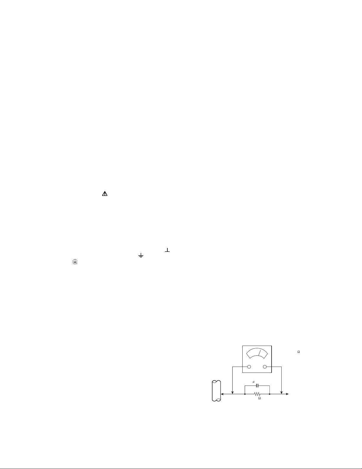
Alternate Check Method
Plug the AC line cord directly into the AC outlet (do not
use a line isolation transformer during this check.). Use
an AC voltmeter having 1000Ω per volt or more
sensitivity in the following manner. Connect a 1500Ω
10W resistor paralleled by a 0.15µF AC-type capacitor
between an exposed metal part and a known good earth
ground (water pipe, etc.). Measure the AC voltage
across the resistor with the AC voltmeter. Move the
resistor connection to each exposed metal part,
particularly any exposed metal part having a return path
to the chassis, and measure the AC voltage across the
resistor. Now, reverse the plug in the AC outlet and
repeat each measurement. Any voltage measured must
not exceed 0.75V AC (r.m.s.). This corresponds to
0.5mA AC (r.m.s.).
However, in tropical area, this must not exceed 0.3V AC
(r.m.s.). This corresponds to 0.2mA AC (r.m.s.).
AC VOLTMETER
(HAVING 1000 /V,
OR MORE SENSITIVITY)
0.15 F AC-TYPE
GOOD EARTH GROUND
1500 10W
PLACE THIS PROBE
ON EACH EXPOSED
ME TAL PAR T
(No.YA604<Rev.001>)1-3
Page 4
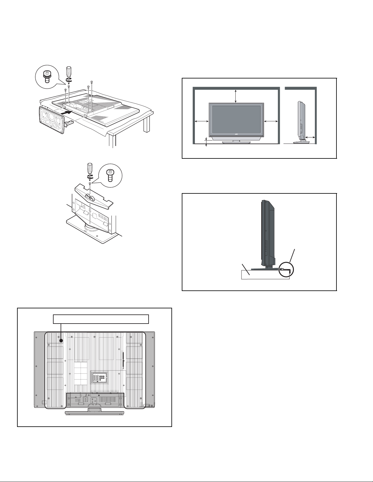
1.2 INSTALLATION
1.2.1 ATTACH THE STAND TO THE TV
When installing the unit on the floor, it is required to attach the
supplied stand.
To attach the stand to the TV, follow the procedure below.
To prevent scratches on the panel, lay a piece of soft cloth on an
even platform and place the TV onto it.
1.2.3 INSTALLATION REQUIREMENTS
Ensure that the minimal distance is maintained, as specified
below, between the unit with and the surrounding walls, as well
as the floor etc.Install the unit on stable flooring or stands.Take
precautionary measures to prevent the unit from tipping in order
to protect against accidents and earthquakes.
200mm
150mm 150mm
50mm
50mm
*The drawing may differ from the actual appearance.
1.2.4 INSTALLATION REQUIREMENTS
To ensure safety in an emergency such as an earthquake, and
to prevent accidents, ensure that measures are taken to prevent
the TV dropping or falling over.
1.2.2 HEAT DISSIPATION
If the heat dissipation vent behind this unit is blocked, cooling
efficiency may deteriorate and temperature inside the unit will
rise. The temperature sensor that protects the unit will be
activated when internal temperature exceeds the pre-determined
level and power will be turned off automatically.Therefore,
please make sure pay attention not to block the heat dissipation
vent as well as the ventilation outlet behind the unit and ensure
that there is room for ventilation around it.
VENTILATION HOLE
*The drawing may differ from the actual appearance.
It fixes in a band.
TV STAND
*The drawing may differ from the actual appearance.
1.2.5 NOTES ON HANDLING
When taking the unit out of a packing case, do not grasp the
upper part of the unit. If you take the unit out while grasping the
upper part, the LCD PANEL may be damaged because of a
pressure. Instead of grasping the upper part, put your hands on
the lower backside or sides of the unit.
1-4 (No.YA604<Rev.001>)
Page 5
1.3 HANDLING LCD PANEL
1.3.1 PRECAUTIONS FOR TRANSPORTATION
When transporting the unit, pressure exerted on the internal LCD
panel due to improper handling (such as tossing and dropping)
may cause damages even when the unit is carefully packed. To
prevent accidents from occurring during transportation, pay
careful attention before delivery, such as through explaining the
handling instructions to transporters.
Ensure that the following requirements are met during
transportation, as the LCD panel of this unit is made of glass and
therefore fragile:
(1) USE A SPECIAL PACKING CASE FOR THE LCD PANEL
When transporting the LCD panel of the unit, use a special
packing case (packing materials). A special packing case
is used when a LCD panel is supplied as a service spare
part.
(2) ATTACH PROTECTION SHEET TO THE FRONT
Since the front (display part) of the panel is vulnerable,
attach the protection sheet to the front of the LCD panel
before transportation. Protection sheet is used when a LCD
panel is supplied as a service spare part.
(3) AVOID VIBRATIONS AND IMPACTS
The unit may be broken if it is toppled sideways even when
properly packed. Continuous vibration may shift the gap of
the panel, and the unit may not be able to display images
properly. Ensure that the unit is carried by at least 2
persons and pay careful attention not to exert any vibration
or impact on it.
(4) DO NOT PLACE EQUIPMENT HORIZONTALLY
Ensure that it is placed upright and not horizontally during
transportation and storage as the LCD panel is very
vulnerable to lateral impacts and may break. During
transportation, ensure that the unit is loaded along the
traveling direction of the vehicle, and avoid stacking them
on one another. For storage, ensure that they are stacked
in 2 layers or less even when placed upright.
1.3.3 PRECAUTIONS FOR REPLACEMENT OF EXTERIOR
PARTS
Take note of the following when replacing exterior parts (REAR
COVER, FRONT PANEL, etc.):
(1) Do not exert pressure on the front of the LCD panel (filter
surface). It may cause irregular colour.
(2) Pay careful attention not to scratch or stain the front of the
LCD panel (filter surface) with hands.
(3) When replacing exterior parts, the front (LCD panel) should
be placed facing downward. Place a mat, etc. underneath
to avoid causing scratches to the front (filter surface).
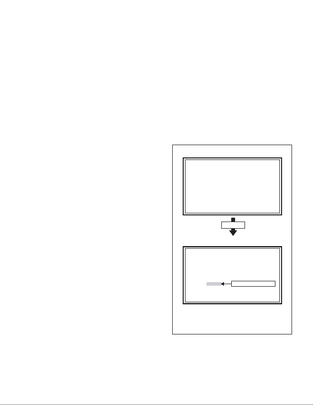
1.3.4 HOW TO CHECK THE OPERATING TIME
This model has a function to count and record the LCD panel
operating time. The operating time can be checked in the
following procedure.
• Maximum count time = 131072 hours
(1) Press the [INFORMATION] key and [MUTING] key
simultaneously, then enter the SERVICE MODE.
(2) Press the [2] key SELF CHECK MODE.
(3) The operating time of the LCD panel is displayed in 6-digit
decimal number.(Refer to the below figure)
SERVICE MODE SCREEN
Service Menu
1.Adjust
2.Self Check
3.I2C Stop
Press [2] key
1.3.2 OPTICAL FILTER (ON THE FRONT OF THE LCD PANEL)
(1) Avoid placing the unit under direct sunlight over a
prolonged period of time. This may cause the optical filter
to deteriorate in quality and colour.
(2) Clean the filter surface by wiping it softly and lightly with a
soft and lightly fuzz cloth (such as outing flannel).
(3) Do not use solvents such as benzene or thinner to wipe the
filter surface. This may cause the filter to deteriorate in
quality or the coating on the surface to come off. When
cleaning the filter, usually use the neutral detergent diluted
with water. When cleaning the dirty filter, use water-diluted
ethanol.
(4) Since the filter surface is fragile, do not scratch or hit it with
hard materials. Be careful enough not to touch the front
surface, especially when taking the unit out of the packing
case or during transportation.
SELF CHECK MODE SCREEN (Page 1)
Self Check
LOB 1
MEM 2 AIO 1
TUN 1 HDM 1
TOS 1
HOUR XXXXXX
Redkey2Page
i:EXIT
*When the power is turned off with the remote control unit or the power
button of the main unit, the count restarts from the turn off time.
*When the power is turned off by disconnecting the power cord from the
AC outlet, the recorded time count less than 2 hours is not counted.
1.3.5 HOW TO RESET THE OPERATING TIME
When the LCD panel unit is replaced, be sure to reset the
operating time in the following method.
(1) Press the [INFORMATION] key and [MUTING] key
simultaneously, then enter the SERVICE MODE.
(2) Press the [9] key, then start the SHIPPING setting.
(3) The power of the UNIT is turned off automatically, and the
OPERATING TIME is reset.
The operating time is displayed.
(No.YA604<Rev.001>)1-5
Page 6
SECTION 2
SPECIFIC SERVICE INSTRUCTIONS
2.1 FEATURES
SUPER SLIM design
The screen surround itself is also very slim, so overall you
have a TV that takes up far less room and is much more like a
picture frame.
FULL HD
Full HD models deliver superbly detailed image reproduction of
more than 2 megapixels (1920 x 1080), which represents double
the resolution offered by WXGA panels.
2.2 MAIN DIFFERENCE LIST
HDMI INPUT
By connecting a HDMI compatible device, high definition
pictures can be displayed on your TV in their digital form.
DIGITAL VNR
This function cuts down the amount of noise in the original
picture.
MaxxBass
This function emphasizes the bass sound.
3D Cinema Sound
You can enjoy sounds with a wider ambience.
ITEM
LT-42S90B/B LT-42S90B/G LT-42S90B/L LT-42S90B/S
MODELS
POWER CORD Round 2PIN type EU Type (2 Pins) Round 2PIN type UK 3PIN type
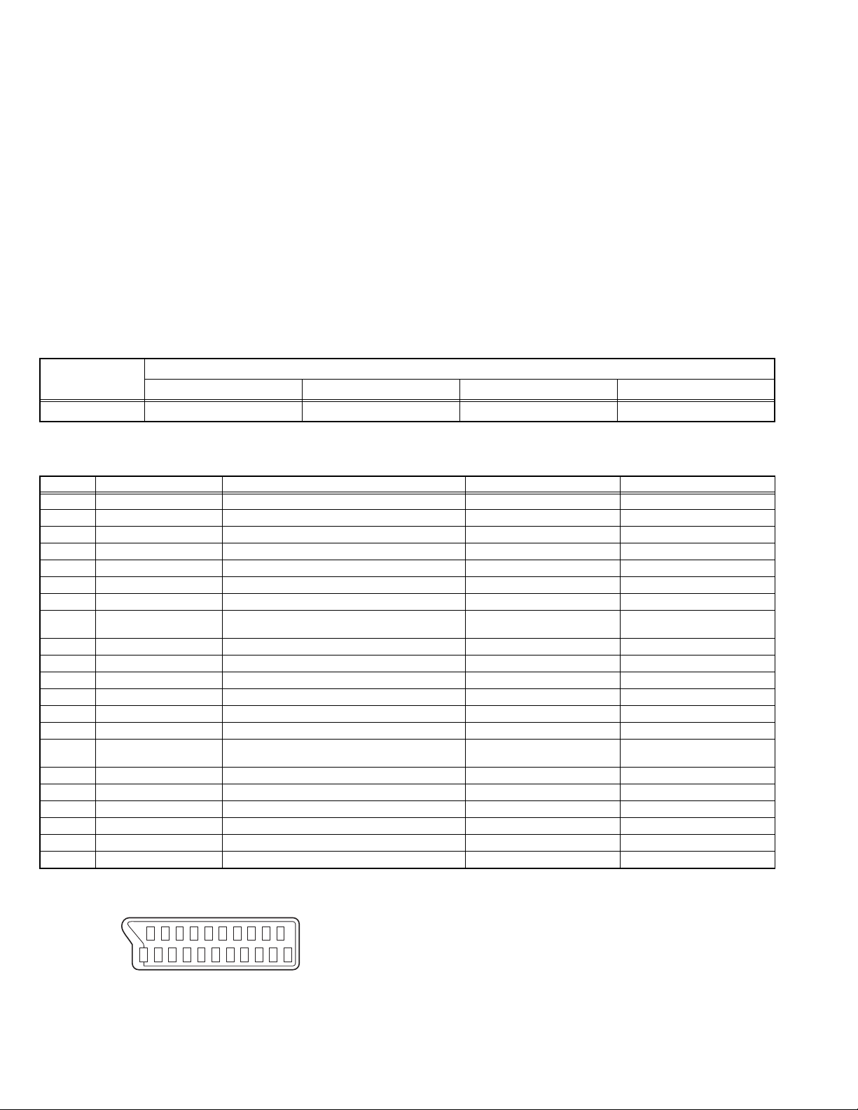
2.3 21-PIN EURO CONNECTOR (SCART) : EXT-1 / EXT-2
Pin No. Signal designation Matching value EXT-1 EXT-2
1 AUDIO R output 500mV(rms) (Nominal), Low impedance Used (TV OUT) Used (LINE OUT)
2 AUDIO R input 500mV(rms) (Nominal), High impedance Used (R1) Used (R2)
3 AUDIO L output 500mV(rms) (Nominal), Low impedance Used (TV OUT) Used (LINE OUT)
4 AUDIO GND Used Used
5 GND (B) Used Used
6 AUDIO L input 500mV(rms) (Nominal), High impedance Used (L1) Used (L2)
7 B input 700mV
8 FUNCTION SW
(SLOW SW)
9 GND (G) Used Used
10 SCL Not used Used (SCL2)
11 G input 700mV
12 SDA Not used Used (SDA2)
13 GND (R) Used Used
14 GND (YS) Used Not used
15 R / C input R : 700mV
16 Ys input (FAST SW) Low : 0V-0.4V, High : 1V-3V, 75Ω Used Not used
17 GND (VIDEO output) Used Used
18 GND (VIDEO input) Used Used
19 VIDEO output 1V
20 VIDEO / Y input 1V
21 COMMON GND Used Used
Low : 0V-3V
High : 8V-12V, High impedance
C : 300mV
(P-P)
(P-P)
, 75Ω Used Not used
(B-W)
Used Used
, 75Ω Used Not used
(B-W)
, 75Ω
(B-W)
, 75Ω
(P-P)
(Negative sync), 75Ω Used (TV OUT) Used (LINE OUT)
(Negative sync), 75Ω Used Used
Used (R) Used (C2)
(P-P= Peak to Peak, B-W= Blanking to white peak)
[Pin assignment]
20 18 16 14 12 10 8 6 4 2
21 19 17 15 13 11 9 7 5 3 1
1-6 (No.YA604<Rev.001>)
Page 7

2.4 TECHNICAL INFORMATION
2.4.1 LCD PANEL
This unit uses the flat type panel LCD (Liquid Crystal Display) panel that occupies as little space as possible, instead of the
conventional CRT (Cathode Ray Tube), as a display unit.
Since the unit has the two polarizing filter that are at right angles to each other, the unit adopts "normally black" mode, where light
does not pass through the polarizing filter and the screen is black when no voltage is applied to the liquid crystals.
2.4.1.1 SPECIFICATIONS
The following table shows the specifications of this unit.
Item Specifications
Maximum dimensions ( W × H × D )
96.3 cm × 55.6 cm × 2.9 cm
Weight 11.0 kg
Effective screen size Diagonal: 106.7 cm (H: 93.0 cm × V: 52.3 cm)
Aspect ratio 16 : 9
Drive device / system a-Si-TFT active matrix system
Resolution Horizontally 1920 × Vertically 1080 × RGB <FULL HD> 6220800 dots in total
Pixel pitch (pixel size) Horizontally: 0.4845 mm, Vertically: 0.4845 mm
Displayed colour 16777216 colours 256 colours for R G and B
Brightness 500 cd/m
2
Contrast ratio 1500 : 1
Response time 6.5 ms
View angle (Horizontally) 178°
View angle (Vertically) 178°
Surface polarizer Anti-Glare type Low reflective coat
Colour filter Vertical stripe
Backlight Cold cathode fluorescent lamp × 22
Power supply voltage in LCD 12 V
Power supply voltage in inverter
24 V
Panel interface system LVDS (Low Voltage Differential Signaling)
2.4.1.2 PIXEL FAULT
There are three pixel faults - bright fault, dark fault and flicker fault - that are respectively defined as follows.
BRIGHT FAULT
In this pixel fault, a cell that should not light originally is lighting on and off.
For checking this pixel fault, input ALL BLACK SCREEN and find out the cell that is lighting on and off.
DARK FAULT
In this pixel fault, a cell that should light originally is not lighting or lighting with the brightness twice as brighter as originally lighting.
For checking this pixel fault, input 100% of each R/G/B colour and find out the cell that is not lighting.
FLICKER FAULT
In the pixel fault, a cell that should light originally or not light originally is flashing on and off.
For checking this pixel fault, input ALL BLACK SCREEN signal or 100% of each RGB colour and find out the cell that is flashing on
and off.
(No.YA604<Rev.001>)1-7
Page 8
2.4.2 MAIN CPU PIN FUNCTION [IC7001
Pin Pin name I/O Function
1KEY1 I
2 ECO SENSER I Eco sensor detection
3 VDD33_GPIO - 3.3V power supply
4 SLOW1 I EXT-1 SLOW detection
5 SLOW2 I EXT-2 SLOW detection
6 AFC1 I AFT voltage for VHF/UHF tuner
7 AGC I RF AGC voltage for VHF/UHF tuner
8 GND - GND
9 VDD33_CADC - 3.3V power supply
10 MONITOR_OUT O Video for EXT-2
11 VDD33_AFE - 3.3V power supply
12 VOUT2 O Not used
VDD12_ADC_1234
13
14 VOUT3 O Not used
15 GND - GND
16 TV_CV I Video for VHF/UHF tuner
17 GND - GND
18 E1_CV I Video for EXT-1
VDD12_ADC_1234
19
20 E2_CV/Y I Video/Y for EXT-2
21 GND - GND
22 AGND1234 I LPF setting
23 VDD33_AFE - 3.3V power supply
24 IDTV_CV I Not used
VDD12_ADC_1234
25
26 IDTV_CR I Cr for digital tuner
27 GND - GND
28 IDTV_Y I Y for digital tuner
29 GND - GND
30 SC_FB1 I Ys for EXT-1
VDD12_ADC_1234
31
32 IDTV_CB I Not used
33 GND - GND
34 SC_R1 I R for EXT-1
35 VDD33_AREF - 3.3V power supply
36 SC_G1 I G for EXT-1
VDD12_ADC_5678
37
38 SC_B1 I B for EXT-1
39 GND - GND
40 AGND5678 I LPF setting
41 GND - GND
42 E2_C I C for EXT-2
VDD12_ADC_5678
43
44 VIN16 I Not used
45 GND - GND
46 VIN17 I Not used
47 VDD33_AREF - 3.3V power supply
48 VIN18 I Not used
VDD12_ADC_5678
49
50 E3_PR I Pr for EXT-3
51 GND - GND
52 E3_Y I Y for EXT-3
53 GND - GND
54 E3_PB I Pb for EXT-3
VDD12_ADC_5678
55
56 VIN22 I Not used
57 GND - GND
58 VDD_CORE - 1V power supply
59 GND - GND
60 SIF_INM I SIF for VHF/UHF tuner
61 TU_SIF I SIF for VHF/UHF tuner
62 VDD12_SIFADC - 1.25V power supply
63 LINE_OUT1R O Audio for EXT-1
64 LINE_OUT1L O Audio for EXT-1
65 TU_R O Audio for EXT-2 or Audio
66 TU_L O Audio for EXT-2 or Audio
67 R_AUSW I Audio
68 L_AUSW I Audio
69 VDD33_AAU - 3.3V power supply
Key scan for side control (POWER/VOL/UP/DOWN)
- 1.25V power supply
- 1.25V power supply
- 1.25V power supply
- 1.25V power supply
- 1.25V power supply
- 1.25V power supply
- 1.25V power supply
- 1.25V power supply
: MAIN PWB]
Pin Pin name I/O Function
70 LINE_IN3R I Not used
71 LINE_IN3L I Not used
72 GND - GND
73 LINE_IN2R I Not used
74 LINE_IN2L I Not used
75 GND - GND
76 LINE_IN1R I Not used
77 LINE_IN1L I Not used
78 VREFAU I Reference voltage setting
79 HP_R O Audio for headphone
80 HP_L O Audio for headphone
81 MAIN_OUT_SUB O Not used
82 M_R O Audio for speaker
83 M_L O Audio for speaker
84 GND - GND
VDD10_HDMI1+2
85
86 HMDI1_RXCN I TMDS clock for HDMI
87 HMDI1_RXCP I TMDS clock for HDMI
88 GND - GND
VDD33_HDMI1+2
89
90 HDMI1_RX0N I TMDS data for HDMI
91 HDMI1_RX0P I TMDS data for HDMI
92 GND - GND
93
VDD10_HDMI1+2
94 HDMI1_RX1N I TMDS data for HDMI
95 HDMI1_RX1P I TMDS data for HDMI
96 GND - GND
VDD33_HDMI1+2
97
98 HDMI1_RX2N I TMDS data for HDMI
99 HDMI1_RX2P I TMDS data for HDMI
100 GND - GND
VDD10_HDMI1+2
101
102 VDD_CORE - 1V power supply
103 GND - GND
VDD10_HDMI1+2
104
105 HMDI2_RXCN I Not used
106 HMDI2_RXCP I Not used
107 GND - GND
108
VDD33_HDMI1+2
109 HDMI2_RX0N I Not used
110 HDMI2_RX0P I Not used
111 GND - GND
VDD10_HDMI1+2
112
113 HDMI2_RX1N I Not used
114 HDMI2_RX1P I Not used
115 GND - GND
VDD33_HDMI1+2
116
117 HDMI2_RX2N I Not used
118 HDMI2_RX2P I Not used
119 GND - GND
120
VDD10_HDMI1+2
121 VDD25_DRAM - 2.5V power supply
122 DRAM_VREF I Reference voltage setting
123 VDD25_DRAM - 2.5V power supply
124 VDD25_DRAM - 2.5V power supply
125 VDD25_DRAM - 2.5V power supply
126 RX_DTV O Not used
127 DIN_HOTP1 O
128 AUDIO_MUTE O
129 VDD33_GPIO - 3.3V power supply
130 LB_PRO I
131 P3.2 I L fixed
132 HM_SDA I/O Data for I2C bus (for HDMI)
133 HM_SCL O Clock for I2C bus (for HDMI)
134 HM_HPLUG2 O
135 HM_HPLUG3 O
136 STATUS I Not used
137 ID_RESET O Not used
138 IRQ O Not used
- 1V power supply
- 3.3V power supply
- 1V power supply
- 3.3V power supply
- 1V power supply
- 1V power supply
- 3.3V power supply
- 1V power supply
- 3.3V power supply
- 1V power supply
Hotplug error detection for HDMI connector-1 [Error = L]
Speaker/headphone output muting [Muting = H]
Power abnormality detection [Emergent = H]
Hotplug error detection for HDMI connector-2 [Error = L]
Hotplug error detection for HDMI connector-3 [Error = L]
1-8 (No.YA604<Rev.001>)
Page 9
Pin Pin name I/O Function
139 TX_DTV I Not used
140 P4.6 I/O Not used
141 P4.7 I/O Not used
142 BL_ON O
143 LCD_POW O
Power on/off control for back-light [ON = L]
Power on/off control for LCD drive [ON = H]
144 VDD33_VIPA - 3.3V power supply
145 TV_LINK_IN I Not used
146 TV LINK_OUT O Not used
147 P2.4 I/O Not used
148 P2.5 I/O Not used
149 P2.6 I/O Not used
150 P2.7 I/O Not used
151 NC I L fixed
152 NC I L fixed
153 NC - GND
154 NC I L fixed
155 P3.0 I L fixed
156 P3.1 I L fixed
157 NC I L fixed
158 VDD33_VIPA - 3.3V power supply
159 NC I L fixed
160 NC I L fixed
161 NC I L fixed
162 VDD33_VIPA - 3.3V power supply
163 NC I L fixed
164 NC I L fixed
165 NC I L fixed
166 SDA0 I/O Data for I
167 SCL0 O Clock for I
2
C bus (for E2PROM)
2
C bus (for E2PROM)
168 PFC O Power on/off control for PFC [ON = L]
169 MAIN_POWER O
Power on/off control for main power [ON = L]
170 VDD - 1V power supply
171 TCLK I Clock for JTAG interface
172 TDI I Data for JTAG interface
173 TDO O Data for JTAG interface
174 TMS I Control signal for JTAG interface
175 GND - GND
176 GND - GND
177 GND - GND
178 GND - GND
179 GND - GND
180 GND - GND
181 VDD33_DAU - 3.3V power supply
182 NC - Not used
183 NC I L fixed
184 NC I L fixed
185 NC I L fixed
186 NC - Not used
187 NC - Not used
188 PWM_DIM O
PWM dimming control for back-light inverter
189 VDD25_PIP - 2.5V power supply
190 DC_DIM O
Not used: DC dimming control for back-light inverter
191 PCS6 O Not used
192 PCS5 O Not used
193 VDD25_PIP - 2.5V power supply
194 PCS4 O Not used
195 PCS3 O Not used
196 VDD25_PIP - 2.5V power supply
197 PCS2 O Not used
198 PCS1 O Not used
199 VDD25_DRAM - 2.5V power supply
200 VDD25_DRAM - 2.5V power supply
201 VDD25_DRAM - 2.5V power supply
202 VDD10_DLL - 1V power supply
203 VDD25_DRAM - 2.5V power supply
204 TE2+ O LVDS data for LCD panel
205 TE2- O LVDS data for LCD panel
206 VDD25_VOPA - 2.5V power supply
207 TD2+ O LVDS data for LCD panel
208 TD2- O LVDS data for LCD panel
Pin Pin name I/O Function
209 GND - GND
210 TCLK2+ O LVDS clock for LCD panel
211 TCLK2- O LVDS clock for LCD panel
212 VDD25_VOPA - 2.5V power supply
213 TC2+ O LVDS data for LCD panel
214 TC2- O LVDS data for LCD panel
215 GND - GND
216 TB2+ O LVDS data for LCD panel
217 TB2- O LVDS data for LCD panel
218 VDD25_VOPA - 2.5V power supply
219 TA2+ O LVDS data for LCD panel
220 TA2- O LVDS data for LCD panel
221 GND - GND
222 GND - GND
223 VDD25_PLL - 2.5V power supply
224 VDD33_FLASH - 3.3V power supply
225 VDD10_PLL - 1V power supply
226 TE1+ O LVDS data for LCD panel
227 TE1- O LVDS data for LCD panel
228 VDD25_VOPA - 2.5V power supply
229 TD1+ O LVDS data for LCD panel
230 TD1- O LVDS data for LCD panel
231 GND - GND
232 TCLK1+ O LVDS clock for LCD panel
233 TCLK1- O LVDS clock for LCD panel
234 VDD25_VOPA - 2.5V power supply
235 TC1+ O LVDS data for LCD panel
236 TC1- O LVDS data for LCD panel
237 GND - GND
238 TB1+ O LVDS data for LCD panel
239 TB1- O LVDS data for LCD panel
240 VDD25_VOPA - 2.5V power supply
241 TA1+ O LVDS data for LCD panel
242 TA1- O LVDS data for LCD panel
243 VDD_CORE - 1V power supply
244 VSENSE I Not used
245 VDD10 - 1V power supply
246 GND - GND
247 XTALIN I X'tal oscillation for CPU system clock
248 XTALOUT O X'tal oscillation for CPU system clock
249 VDD33_GPIO - 3.3V power supply
250 RESET I CPU reset [Reset = L]
251 SDA1 I/O Data for I
252 SCL1 O
Clock for
2
C bus (for tuner/MaxxBass)
I2C
bus (for tuner/MaxxBass)
253 VDD33_STDB - 3.3V power supply
254 VDD10_STDB - 1V power supply
255 REMOCON I Remote control sensor
256 HM_POWER I Power status detect for HDMI
(No.YA604<Rev.001>)1-9
Page 10

SECTION 3
DISASSEMBLY
3.1 CAUTION AT DISASSEMBLY
• Make sure that the power cord is disconnected from the outlet.
• Pay special attention not to break or damage the parts.
• Make sure that there is no bent or stain on the connectors before inserting, and firmly insert the connectors.
• Be sure to reattach the wire clamps removed during the procedure to the original positions. (Attaching the wire clamps in wrong
positions may affect the performance.)
REFERENCE:
When removing each board, remove the connector if necessary. The operation is easier if you write down the connection points
(connector numbers) of the connector. For connection of each board, refer to the "WIRING DIAGRAM" of the Standard Circuit
Diagram.
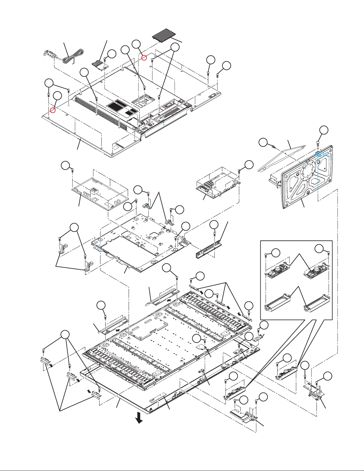
3.2 DISASSEMBLY PROCEDURE
3.2.1 REMOVING THE REAR COVER (Fig.3-1)
(1) Remove the 1 screw [A].
(2) Remove the STAND COVER.
(3) Remove the 1 screw [B].
(4) Remove the POWER CORD COVER.
(5) Remove the POWER CORD.
(6) Remove the JACK COVER.
(7) Remove the 2 hooks [a], 10 screws [C], 5 screws [D], 5
screws [E] and 1 screw [F].
(8) Remove the REAR COVER.
3.2.2 REMOVING THE POWER UNIT (Fig.3-1)
• Remove the STAND COVER.
• Remove the REAR COVER.
• Remove the POWER CORD.
(1) Remove the 6 screws [G].
(2) Remove the POWER UNIT.
3.2.3 REMOVING THE MAIN PWB (Fig.3-1)
• Remove the STAND COVER.
• Remove the REAR COVER.
(1) Remove the 1 screw [H].
(2) Remove the TERMINAL BASE.
(3) Remove the 7 screws [J].
(4) Remove the MAIN PWB.
3.2.6 REMOVING THE HP/USB PWB (Fig.3-1)
• Remove the STAND COVER.
• Remove the REAR COVER.
(1) Remove the 1 screw [N].
(2) Remove the HP/USB PWB.
3.2.7 REMOVING THE LED PWB, LED LENS (Fig.3-1)
• Remove the STAND COVER.
• Remove the REAR COVER.
(1) Remove the 1 screw [P].
(2) Remove the LED PWB.
(3) Remove the LED LENS.
3.2.8 REMOVING THE SPEAKER (Fig.3-1)
• Remove the STAND COVER.
• Remove the REAR COVER.
(1) Remove the 4 screws [Q].
(2) Remove the SPEAKER HOLDER.
(3) Remove the 4 screws [R].
(4) Remove the SPEAKER.
3.2.9 REMOVING THE STAND ASS’Y (Fig.3-1)
• Remove the STAND COVER.
(1) Remove the 4 screws [S].
(2) Remove the STAND.
3.2.4 REMOVING THE CAPSENS PWB (Fig.3-1)
• Remove the STAND COVER.
• Remove the REAR COVER.
(1) Remove the CAPSENS PWB by carefully peeling off the
double faced tape.
3.2.5 REMOVING THE IR PWB (Fig.3-1)
• Remove the STAND COVER.
• Remove the REAR COVER.
(1) Remove the 1 screw [M].
(2) Remove the IR PWB.
1-10 (No.YA604<Rev.001>)
3.2.10 REMOVING THE LCD PANEL UNIT (Fig.3-1)
• Remove the STAND COVER.
• Remove the REAR COVER.
• Remove the STAND.
(1) Remove the 3 screws [T] and 2 screws [U].
(2) Remove the STAND SUPPORT.
(3) Remove the 8 screws [V].
(4) Remove the BACK BRACKET.
(5) Remove the 4 screws [W].
(6) Remove the MAIN BASE.
(7) Remove the 6 screws [X].
(8) Slide the SIDE BRACKET in the direction of the arrow to
remove it.
(9) Remove the 4 screws [Y].
(10) Slide the TOP BRACKET in the direction of the arrow to
remove it.
(11) Lift up the LCD PANEL UNIT to remove it.
Page 11
POWER CORD
C
aa
REAR COVER
POWER CORD COVER
B
D
aa
F
JACK COVER
D
C
E
S
STAND COVER
A
BACK
BRACKET
G
POWER UNIT
V
TOP BRACKET
X
Y
V
W
MAIN BASE
TOP BRACKET
BACK
BRACKET
Y
V
W
MAIN PWB
X
X
P
TERMINAL BASE
H
SIDE BRACKET
J
X
M
<SPEAKER>
R
SPEAKER HOLDER
N
HP/USB PWB
STAND
SPEAKER
R
SIDE BRACKET
FRONT PANEL
FRONT
CAPSENS PWB
Fig.3-1
LED PWB
LED LENS
Q
IR PWB
U
STAND SUPPORT
Q
U
T
T
STAND
SUPPORT
(No.YA604<Rev.001>)1-11
Page 12
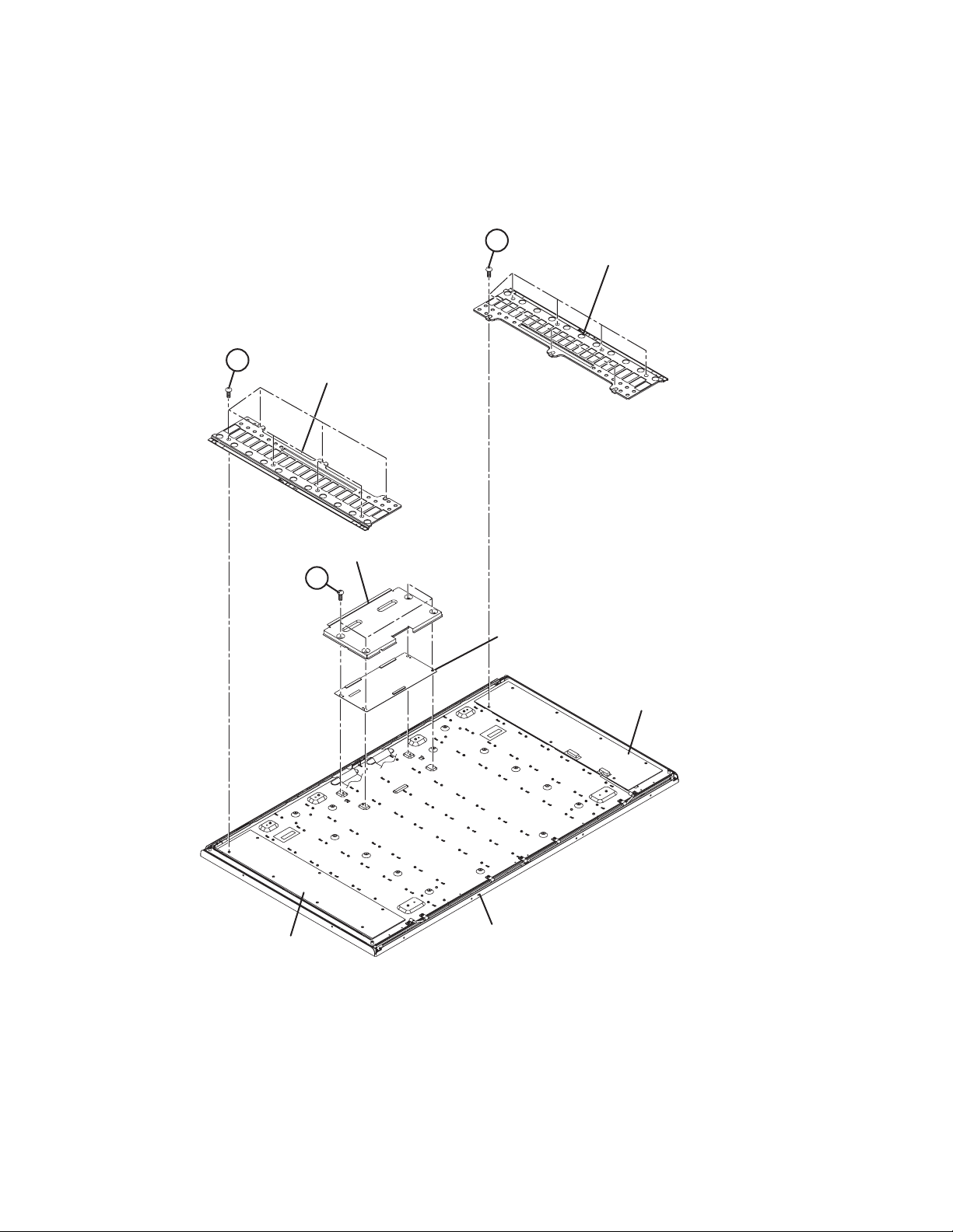
3.2.11 REMOVING THE LCD CONTROL PWB (Fig.3-2)
• Remove the STAND COVER.
• Remove the REAR COVER.
• Remove the MAIN BASE.
(1) Remove the 4 screws [A].
(2) Remove the LCD CONTROL PWB COVER.
(3) Remove the LCD CONTROL PWB.
BB
INVERTER PWB COVER
3.2.12 REMOVING THE INVERTER PWB (Fig.3-2)
• Remove the STAND COVER.
• Remove the REAR COVER.
• Remove the SIDE BRACKET.
(1) Remove the 6 screws [B].
(2) Remove the INVERTER PWB COVER.
(3) Remove the INVERTER PWB.
(4) Follow the same steps when removing the other
INVERTER PWB.
BB
INVERTER PWB COVER
LCD CONTROL PWB COVER
AA
INVERTER PWB (MASTER)
LCD CONTROL PWB
INVERTER PWB (SLAVE)
LCD PANEL UNIT
Fig.3-2
1-12 (No.YA604<Rev.001>)
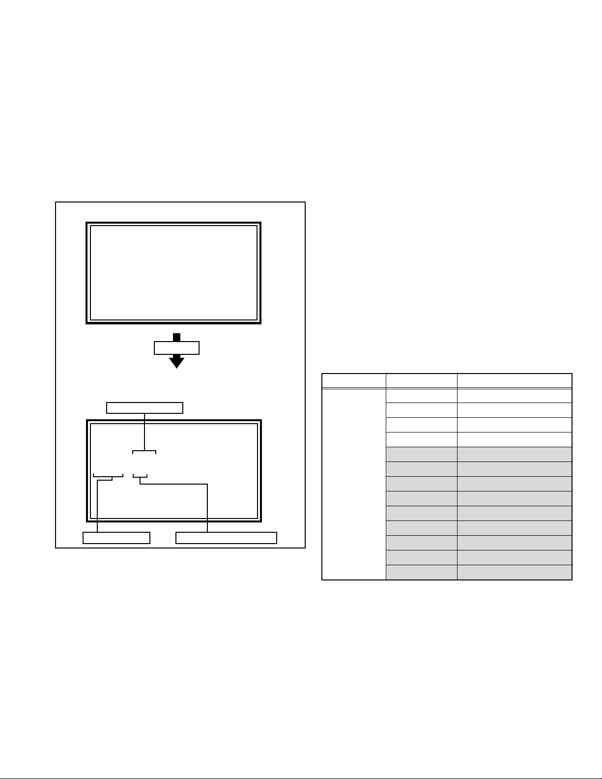
Page 13
3.3 MEMORY IC REPLACEMENT
• This model uses the memory IC.
• This memory IC stores data for proper operation of the video and drive circuits.
• When replacing, be sure to use an IC containing this (initial value) data.
3.3.1 MEMORY IC TABLE
Symbol Number of pins Mounting PWB Main content of data
IC7003
8-pin MAIN PWB Setting value of IC7001(MAIN CPU) is memorized.
3.3.2 MEMORY IC REPLACEMENT PROCEDURE
1. Power off
Switch off the power and disconnect the power plug from the AC outlet.
2. Replace the memory IC
Be sure to use the memory IC written with the initial setting values.
3. Power on
Connect the power plug to the AC outlet and switch on the power.
4. Receiving channel setting
Refer to the OPERATING INSTRUCTIONS and set the receive channels (Channels Preset) as described.
5. User setting
Check the user setting items according to the given in page later. Where these do not agree, refer to the OPERATING
INSTRUCTIONS and set the items as described.
6. SERVICE MODE setting
Verify what to set in the SERVICE MODE, and set whatever is necessary (Fig.3-3). Refer to the SERVICE ADJUSTMENT for
setting.
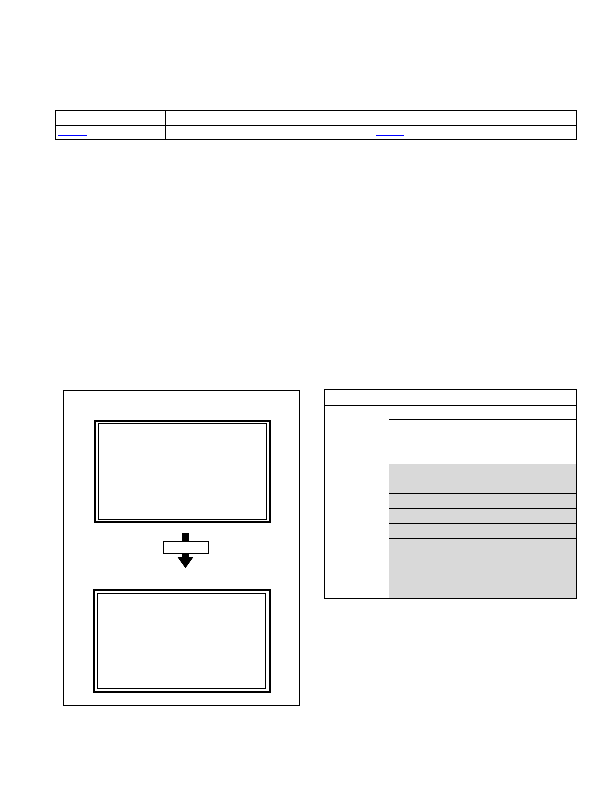
3.3.3 SERVICE MODE SETTING
SERVICE MODE SCREEN
SERVICE MODE SCREEN
Service Menu
1.Adjust
2.Self Check
3.I2C Stop
Press [1] key
ADJUST MODE SCREEN
Adjust PAL BG
1.SC ADJ 15
SC DEV : +00
OK:Store i:Exit
SETTING ITEM
Setting mode Setting items Settings
1.ADJUST 1.SC ADJ. Adjust
2.R DRIVE Adjust
3.G DRIVE Adjust
4.B DRIVE Adjust
5.CUTOFF R Fixed [Do not adjust]
6.CUTOFF G Fixed [Do not adjust]
7.CUTOFF B Fixed [Do not adjust]
8.COLOUR Fixed [Do not adjust]
9.HUE Fixed [Do not adjust]
10.CONT. Fixed [Do not adjust]
11.BRIGHT2 Fixed [Do not adjust]
12.SHARP Fixed [Do not adjust]
13.CORING Fixed [Do not adjust]
Fig.3-3
(No.YA604<Rev.001>)1-13
Page 14
3.3.4 SETTINGS OF FACTORY SHIPMENT
3.3.4.1 BUTTON OPERATION 3.3.4.2 REMOTE CONTROL DIRECT OPERATION
Setting item Setting position
POWER Off
CHANNEL PR1
VOLUME 10
TV/AV TV
3.3.4.3 REMOTE CONTROL MENU OPERATION
(1) PICTURE
Setting item Setting position
Picture Mode Bright
Colour Temp. Cool
FEATURES
Digital VNR RF Auto
OTHER On
DigiPure On
Movie Theatre Off
Colour Management On
Picture Management On
Smart Picture On
Dynamic Backlight On
MPEG Noise Reduction On
Colour System TV Depends on PR/CH
EXT Auto
4:3 Auto Aspect Panoramic
CHANNEL PR1
VOLUME 10
ZOOM Auto
SUB POWER Off
VIDEO-3 COMPONENT / COMPOSITE
(3) FEATURES
Sleep Timer Off
Child Lock Off (ID:0000)
Blue Back On
Favourite Setting Blank
Power Lamp On
Eco Sensor Off
(4) SET UP
Auto Program TV Channel Automatically Set
Edit / manual Preset Ch Only
Language English
Ext Setting Ext-1
HDMI-1 Audio Setting Auto
Setting item Setting position
Component
Setting item Setting position
Setting item Setting position
(2) SOUND
Setting item Setting position
STEREO / I•II Stereo sound
Bass Centre
Treble Centre
Balance Centre
Hyper Sound Off
MaxxBass Low
3D CINEMA SOUND
Sorrund Mid
Bass Boost Mid
Auto Volume Control Off
1-14 (No.YA604<Rev.001>)
Page 15
3.4 REPLACEMENT OF CHIP COMPONENT
3.4.1 CAUTIONS
(1) Avoid heating for more than 3 seconds.
(2) Do not rub the electrodes and the resist parts of the pattern.
(3) When removing a chip part, melt the solder adequately.
(4) Do not reuse a chip part after removing it.
3.4.2 SOLDERING IRON
(1) Use a high insulation soldering iron with a thin pointed end of it.
(2) A 30w soldering iron is recommended for easily removing parts.
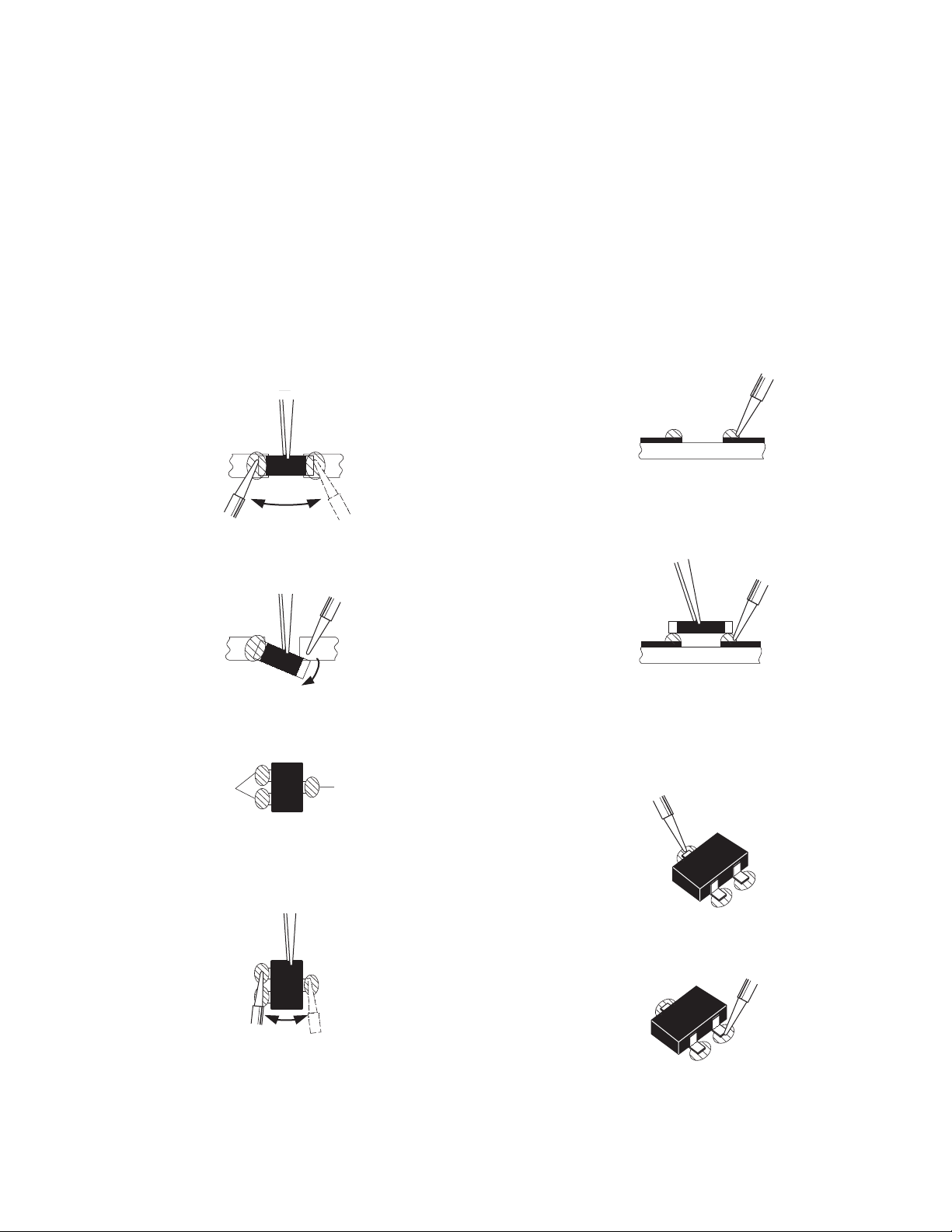
3.4.3 REPLACEMENT STEPS
1. How to remove Chip parts
2. How to install Chip parts
[Resistors, capacitors, etc.]
(1) As shown in the figure, push the part with tweezers and
alternately melt the solder at each end.
(2) Shift with the tweezers and remove the chip part.
[Transistors, diodes, variable resistors, etc.]
(1) Apply extra solder to each lead.
SOLDER
SOLDER
[Resistors, capacitors, etc.]
(1) Apply solder to the pattern as indicated in the figure.
(2) Grasp the chip part with tweezers and place it on the
solder. Then heat and melt the solder at both ends of the
chip part.
[Transistors, diodes, variable resistors, etc.]
(1) Apply solder to the pattern as indicated in the figure.
(2) Grasp the chip part with tweezers and place it on the
solder.
(3) First solder lead A as indicated in the figure.
(2) As shown in the figure, push the part with tweezers and
alternately melt the solder at each lead. Shift and remove
the chip part.
NOTE :
After removing the part, remove remaining solder from the
pattern.
A
B
C
(4) Then solder leads B and C.
A
B
C
(No.YA604<Rev.001>)1-15
Page 16
SECTION 4
ADJUSTMENT
4.1 ADJUSTMENT PREPARATION
(1) This TV is adjusted by using REMOTE CONTROL UNIT.
(2) The adjustment using the REMOTE CONTROL UNIT is made on the basis of the initial setting values. The setting values
which adjust the screen to the optimum condition can be different from the initial setting values.
(3) Make sure that connection is correctly made AC to AC power source.
(4) Turn on the power of the TV and measuring instruments for warming up for at least 30 minutes before starting adjustments.
(5) If the receive or input signal is not specified, use the most appropriate signal for adjustment.
(6) Never touch the parts (such as variable resistors, transformers and condensers) not shown in the adjustment items of this service
adjustment.
4.2 PRESET SETTING BEFORE ADJUSTMENTS
Unless otherwise specified in the adjustment items, preset the
following functions with the REMOTE CONTROL UNIT.
Setting item Settings position
PICTURE MODE STANDARD
PICTURE adjustments Centre
COLOUR TEMP. NORMAL
Colour Management Off
Picture Management Off
Smart Picture Off
Dynamic Backlight Off
Eco Sensor Off
4.3 MEASURING INSTRUMENT AND FIXTURES
• Signal generator (Pattern generator)[PAL]
• Remote control unit
4.4 ADJUSTMENT ITEMS
VIDEO CIRCUIT
• COLOUR DECODER adjustment
• WHITE BALANCE (HIGH LIGHT) adjustment
4.5.2 HOW TO EXIT THE SERVICE MODE
Press the [MENU] key to exit the Service mode.
4.5.3 CHANGE AND MEMORY OF SETTING VALUE
SELECTION OF SETTING ITEM
• [FUNCTION /] key.
For scrolling up / down the setting items.
CHANGE OF SETTING VALUE (DATA)
• [FUNCTION /] key.
For scrolling up / down the setting values.
MEMORY OF SETTING VALUE (DATA)
Changed setting value is memorized by pressing [OK] key.
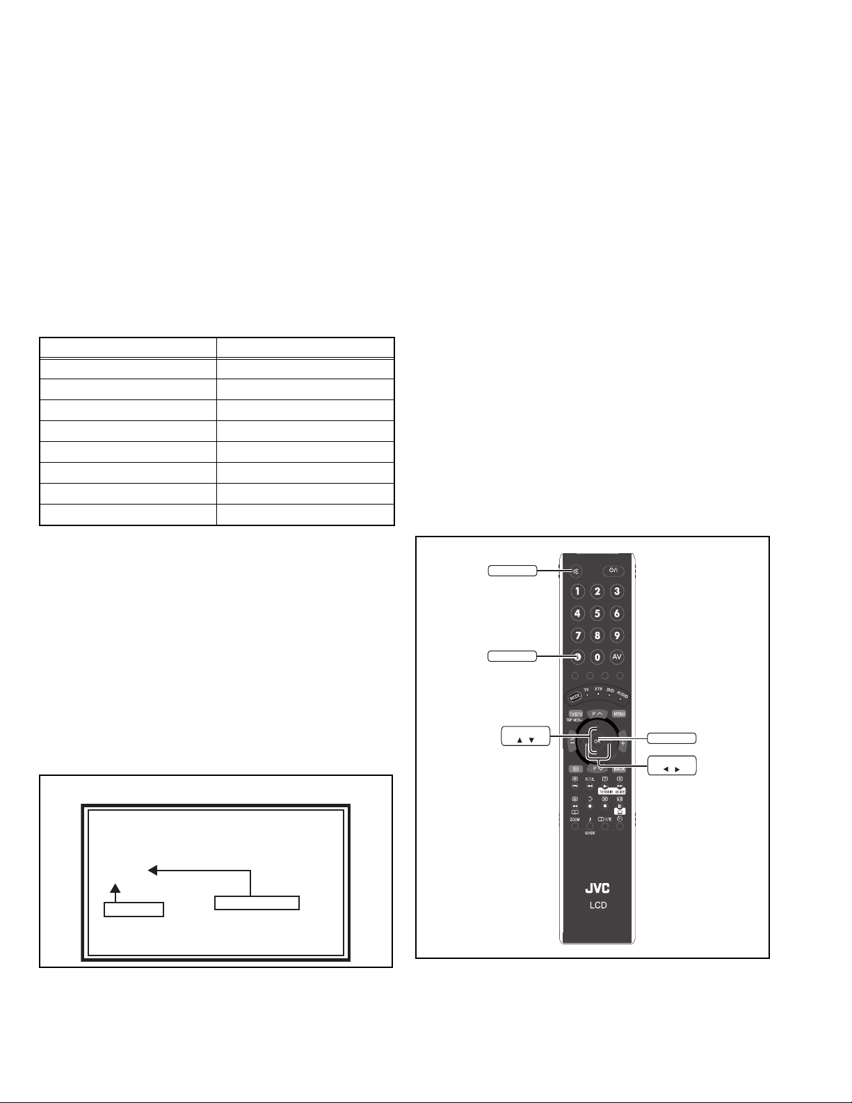
4.5.4 SERVICE MODE SELECT KEY LOCATION
MUTING
INFORMATION
4.5 BASIC OPERATION OF SERVICE MODE
4.5.1 HOW TO ENTER THE SERVICE MODE
(1) Press [INFORMATION] key and [MUTING] key on the
remote control unit simultaneously to enter the SERVICE
MODE SCREEN.
SERVICE MODE SCREEN
Service Menu
1.Adjust
2.Self Check
3.I2C Stop
NOT USED
NOTE:
Before entering the SERVICE MODE, confirm that the setting
of TV/STB/DVD/AUDIO mode is at the "TV" side. If the
switches have not been properly set, you cannot enter the
SERVICE MODE.”
1-16 (No.YA604<Rev.001>)
Refer to SECTION5
FUNCTION
/
OK
FUNCTION
/
Page 17
4.5.5 ADJUSTMENT MODE
This mode is used to adjust the VIDEO CIRCUIT.
4.5.5.1 HOW TO ENTER THE ADJUSTMENT MODE
When the SERVICE MENU SCREEN of SERVICE MODE is
displayed, press [1] key to enter the ADJUSTMENT MODE.
NOTE:
• When a number key other than the [1] key is pressed in the
SERVICE MODE SCREEN, the other relevant screen may
be displayed.
This is not used in the adjustment procedure. Press the
[MENU] key to return to the SERVICE MODE SCREEN.
4.5.5.2 DESCRIPTION OF STATUS DISPLAY
SERVICE MODE SCREEN
Service Menu
1.Adjust
2.Self Check
3.I2C Stop
(1) SIGNAL SYSTEM
The signal displayed on the screen is displayed.
480 60i : 480i (Component) / HDMI 480i
576 50i : 576i (Component) / HDMI 576i
480 60p : 480p (Component) / HDMI 480p
480 60p VGA : HDMI 480p VGA
576 50p : 576p (Component) / HDMI 576p
720 50p : 720p 50Hz (Component) / HDMI 720p 50Hz
720 60p : 720p 60Hz (Component) / HDMI 720p 60Hz
1080 60i : 1080i 60Hz (Component) / HDMI 1080i 60Hz
1080 50i : 1080i 50Hz (Component) / HDMI 1080i 50Hz
1080 60p : 1080p 60Hz (Component) / HDMI 1080p 60Hz
1080 50p : 1080p 50Hz (Component) / HDMI 1080p 50Hz
1080 24p : HDMI 1080p 24Hz
PAL BG : PAL 50Hz(Composite / S-video)
SECAM : SECAM
NTSC3.58 : NTSC3.58
NTSC4.43 : NTSC4.43
PAL 60 : PAL 60Hz(Composite / S-video)
PAL M : PAL M
PAL N : PAL N
RGB 480i : RGB 480i
RGB 576i : RGB 576i
Undefined : Other than those above
Press [1] key
ADJUST MODE SCREEN
(1) SIGNAL SYSTEM
Adjust 576 50i
2.R DRIVE XXXX
OK:Store i:Exit
(3) SETTING VALUE (DATA)(2) SETTING ITEM
(2) SETTING ITEM NAME
Setting item name are displayed. The setting item numbers to
be displayed are listed below.
Setting mode Setting items Settings
1.ADJUST 1.SC ADJ. Adjust
2.R DRIVE Adjust
3.G DRIVE Adjust
4.B DRIVE Adjust
5.CUTOFF R Fixed [Do not adjust]
6.CUTOFF G Fixed [Do not adjust]
7.CUTOFF B Fixed [Do not adjust]
8.COLOUR Fixed [Do not adjust]
9.HUE Fixed [Do not adjust]
10.CONT. Fixed [Do not adjust]
11.BRIGHT2 Fixed [Do not adjust]
12.SHARP Fixed [Do not adjust]
13.CORING Fixed [Do not adjust]
(3) SETTING VALUE (DATA)
The SETTING VALUE is displayed.
(No.YA604<Rev.001>)1-17
Page 18
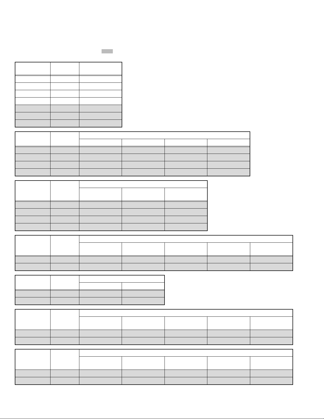
4.6 INITIAL SETTING VALUES IN THE SERVICE MODE
• Perform fine-tuning based on the "initial values" using the remote control when in the Service mode.
• The "initial values" serve only as an indication rough standard and therefore the values with which optimal display can be achieved
may be different from the default values.
• Never change the values of the items ( ) that are not described in ADJUSTMENT PROCEDURE or in the below table as they
are fixed values.
Item name
1.SC ADJ. 0 - 63 19
2.R DRIVE 0 - 1024 512
3.G DRIVE 0 - 1024 491
4.B DRIVE 0 - 1024 512
5.CUTOFF R -1024 - 1023 0
6.CUTOFF G -1024 - 1023 0
7.CUTOFF B -1024 - 1023 0
Variable
range
Setting value
Item name
8.COLOUR 0 - 256 132 145 98 98
9.HUE -64 - 64 -2 -4 -2 -5
10.CONTRAST 0 - 256 140 140 140 140
11.BRIGHT-2 -1024 - 1023 -3 -11 -3 -11
Item name
8.COLOUR 0 - 256 127 140 130
9.HUE -64 - 64 -3 -4 -4
10.CONTRAST 0 - 256 135 140 118
11.BRIGHT-2 -1024 - 1023 -15 -3 -23
Item name
12.SHARP 0 - 63 32 32 37 32 32
13.CORING 0 - 63 5 5 5 0 2
Item name
12.SHARP 0 - 63 32 32
13.CORING 0 - 63 2 0
Variable
range
Variable
range
Variable
range
Variable
range
PAL (EXT) PAL (RF) SECAM (EXT) SECAM (RF)
Setting value
NTSC_M /
NTSC4.43
CONPOSITE_50Hz
S-VIDEO_50Hz
RGB 576i TEXT TWIN
/
PAL (RF) / SECAM
Setting value
Setting value
RGB
(RF)
Component /
HDMI
Setting value
CONPOSITE_60Hz
S-VIDEO_60Hz
/
NTSC_RF RGB 480i
Item name
12.SHARP 0 - 63 35 35 35 35 37
13.CORING 0 - 63 2 2 2 2 2
Item name
12.SHARP 0 - 63 37 37 37 37 37
13.CORING 0 - 63 2 2 2 2 2
1-18 (No.YA604<Rev.001>)
Variable
range
Variable
range
Component 480i Component 576i Component 480p Component 576p
Component 720p60 /
Component 1080i60
Component
1080p50
Setting value
Setting value
Component
1080p60
Component 1080i50 /
Component 1080p50
Component 720p50
Component 1080i50
Component 1080i60 /
Component 1080p60
/
Page 19

Setting value
HDMI 720p50 /
HDMI 1080i50
Item name
Variable
range
HDMI 480i HDMI 576i HDMI 480p HDMI 576p
12.SHARP 0 - 63 35 35 35 35 38
13.CORING 0 - 63 2 2 2 2 2
Setting value
HDMI 1080i50 /
HDMI 1080p50
HDMI 1080i60 /
HDMI 1080p60
HDMI 1080p24
Item name
Variable
range
HDMI 1080p50 HDMI 1080p60
12.SHARP 0 - 63 38 38 38 38 38
13.CORING 0 - 63 2 2 2 2 2
4.7 ADJUSTMENT PROCEDURE
4.7.1 VIDEO CIRCUIT
Item
COLOUR
DECODER
Measuring
instrument
Remote
control unit
Test point Adjustment part Description
[1.ADJUST]
1.SC ADJ
(1) Receive a PAL colour bar signal.
(2) Select "1.ADJUST" from the SERVICE MODE.
(3) Select <1.SC ADJ>.
Signal
generator
(4) Adjust the value of <1.SC ADJ> to set the value
of (A) to 0±3.
NOTE:
The value of <1.SC ADJ> should be adjusted
within 7 - 24.
Adjust PAL BG
1.SC ADJ 15
SC DEV : +00
OK:Store i:Exit
(A)
(5) Press the [OK] key to memorize the set value.
WHITE
BALANCE
(HIGHLIGHT)
Remote
control unit
Signal
generator
[1.ADJUST]
2.R DRIVE
3.G DRIVE
4.B DRIVE
(1) Receive a PAL 75% all white signal.
(2) Set PICTURE MODE to "STANDARD".
(3) Set ZOOM to "FULL".
(4) Set COLOUR TEMP. to "NORMAL".
(5) Select "1.ADJUST" from the SERVICE MODE.
(6) Adjustment is select 1 item from <2.R DRIVE>,
<3.G DRIVE> and <4.B DRIVE> then select item
fix to "512" Other color shold be less than 920.
NOTE:
Finaly minimam more than 1 item (<2.R
DRIVE>, <3.G DRIVE> or <4.B DRIVE>)
should be "512".
(7) Must check white balance adjustment correctry
with low light to high light.
(8) Press the [OK] key to memorize the set value.
(No.YA604<Rev.001>)1-19
Page 20

SECTION 5
TROUBLESHOOTING
5.1 SELF CHECK FEATURE
5.1.1 OUTLINE
This unit comes with the "Self check" feature, which checks the
operational state of the circuit and displays/saves it during
failure.Diagnosis is performed when power is turned on, and
information input to the main microcomputer is monitored at all
time.Diagnosis is displayed in 2 ways via screen display and LED
flashes. Failure detection is based on input state of I
2
C bus and
the various control lines connected to the main microcomputer.
5.1.2 HOW TO ENTER THE SELF CHECK MODE
Before enter the SELF CHECK MODE, press the [MODE] key to
confirm that "TV" position is indicated. If it is in a wrong position,
the SELF CHECK MODE operation cannot be performed.
(1) Press the [INFORMATION] key and [MUTING] key
simultaneously, then enter the SERVICE MODE.
(2) Press the [2] key SELF CHECK MODE.
(3) Press the [RED] key to enter Page 2 of the SELF CHECK
MODE.
*Use the [GREEN] key to toggle between Page 1 and Page 2.
NOTE:
When a number key other than the [2] key is pressed in the
SERVICE MODE screen, the other relevant screen may be
displayed.
This is not used in the SELF CHECK MODE. Press the
[MENU] key to return to the MAIN MENU SCREEN.
5.1.3 HOW TO EXIT THE SELF CHECK MODE
To Save Failure History:
Turn off the power by unplugging the AC power cord plug when
in the Self check display mode.
To Clear (Reset) Failure History:
Turn off the power by pressing the [POWER] key on the remote
control unit when in the Self check display mode.
SERVICE MODE SCREEN
Service Menu
1.Adjust
2.Self Check
3.I2C Stop
NOT USED
Press [2] key
SELF CHECK MODE SCREEN (Page 1)
Self Check
LOB 1
MEM 2 AIO 1
TUN 1 HDM 1
TOS 1
HOUR XXXXXX
Redkey2Page
i:EXIT
Refer to SECTION1
Press [Red] key
Item
Failure history
Press [Green] key
SELF CHECK MODE SCREEN (Page 2)
5.1.4 FAILURE HISTORY
Failure history can be counted up to 9 times for each item. When
the number exceeds 9, display will remain as 9. Failure history
will be stored in the memory unless it has been deleted.
NOTE:
Only SYN (with/without sync signals) will be neither counted
nor stored.
5.1.5 POINTS TO NOTE WHEN USING THE SELF CHECK
FEATURE
In addition to circuit failures (abnormal operation), the following
cases may also be diagnosed as "Abnormal" and counted.
(1) Temporary defective transmissions across circuits due to
pulse interruptions.
(2) Misalignment in the on/off timing of power for I
2
C bus (Vcc)
when turning on/off the main power.
Therefore, turn on the main power, and then wait for about 3
seconds before starting Self check.
If recurrences are expected, ensure to clear (reset) the failure
history and record the new diagnosis results.
1-20 (No.YA604<Rev.001>)
Self Check
SYN OK CDN 00
ADS 00 ADH 00
PPL 600 LPF 137
INT 0 FMT 00
FMD FF
Greenkey1Page
i:EXIT
Fig.5-1
Failure history
Diagnosis
OK:Normal
NG:Abnormal
Item
Page 21

5.1.6 DETAILS
Self check is performed for the following items:
<Page 1 of screen>
Detection item Display Detection content
Low bias line short
protection
LOB Confirm the operation of the low bais(1V/3.3V/5V)
protection circuit.
1V: Q9351
3.3V: Q9601
5V: Q9201
[MAIN PWB]
[MAIN PWB]
[MAIN PWB]
MAIN MEMORY MEM Confirmation of reply of ACK signal which uses
I2C communication.
[MAIN PWB]
IC7003
AUDIO AIO Confirmation of reply of ACK signal which uses
RF (ANALOG) TUNER TUN Confirmation of reply of ACK signal which uses
2
C communication.
I
[MAIN PWB]
IC6661
2
C communication.
I
TU1001
[MAIN PWB]
HDMI HDM Confirmation of the internal determination
processing of HDMI.
[MAIN PWB]
IC8501
TOUCH SENSOR TOS Count how many times to reset the touch sensor
circuit.
[CAPSENS PWB]
IC7701
Diagnosis
signal (line)
Detection timing
LB_PRO Detection starts 5 seconds after
the power is turned on. If error
continues between 200 ms the
power is turned off.
SDA If it checks whenever I2C
communication is performed and
no reply of ACK signal an error
will be counted.
SDA If it checks whenever I2C
communication is performed and
no reply of ACK signal an error
will be counted.
SDA If it checks whenever I
2
communication is performed and
no reply of ACK signal an error
will be counted.
--- When an excessive load hangs to
the interrupt to the internal
determination of HDMI, an error
will be counted.
XRES The number of times the main
CPU outputs reset signal is
counted according to an error of
the touch sensor circuit.
C
<Page 2 of screen> indicates items not used for services as they are for designing.
Detection item Display Detection content Detection timing
SYNC SIGNAL SYN Confirmation of presence of sync signal in
selected video signal.
[MAIN PWB]
IC7001
The selected video input signal is always
checked and if there is the sync signal, it is
displayed as "OK", and if not as "NG".
For designing CDN - -
For designing ADS - -
For designing ADH - -
For designing PPL - -
For designing LPF - -
For designing INT - -
For designing FMT - -
5.1.7 METHOD OF DISPLAY WHEN A RASTER IS NOT OUTPUT
In the state where a raster is not output by breakdown of the set, an error is displayed by blink of the POWER LED.
Type of error POWER LED flash cycle
Low bias line short protection Blue turnig on and off at 1 second intervals.
< Explanation of operation >
If error is detected, the power is turned off. Shortly after the power is turned off, POWER LED will be blinked.
When the protection of low bias line short operates, the power cannot be turned on until the power cord takes out and inserts, after
the power is turned off.
(No.YA604<Rev.001>)1-21
Page 22

Victor Company of Japan, Limited
Display category 12, 3-chome, Moriya-cho, Kanagawa-ku, Yokohama-city, Kanagawa-prefecture, 221-8528, Japan
(No.YA604<Rev.001>)
Printed in Japan
VPT
Page 23

PARTS LIST
CAUTION
J The parts identified by the symbol are important for the safety . Whenever replacing these parts, be sure to use specified ones to secure the
safety.
J The parts not indicated in this Parts List and those which are filled with lines --- in the Parts No. columns will not be supplied.
J P.W. BOARD Ass'y will not be supplied, but those which are filled with the Parts No. in the Parts No. columns will be supplied.
ABBREVIATIONS OF RESISTORS, CAPACITORS AND TOLERANCES
RESISTORS CAPACITORS
CR Carbon Resistor C CAP. Ceramic Capacitor
FR Fusible Resistor E CAP. Electrolytic Capacitor
PR Plate Resistor M CAP. Mylar Capacitor
VR Variable Resistor CH CAP. Chip Capacitor
HV R High Voltage Resistor HV CAP. High Voltage Capacitor
MF R Metal Film Resistor MF CAP. Metalized Film Capacitor
MG R Metal Glazed Resistor MM CAP. Metalized Mylar Capacitor
MP R Metal Plate Resistor MP CAP. Metalized Polystyrol Capacitor
OM R Metal Oxide Film Resistor PP CAP. Polypropylene Capacitor
CMF R Coating Metal Film Resistor PS CAP. Polystyrol Capacitor
UNF R Non-Flammable Resistor TF CAP. Thin Film Capacitor
CH V R Chip Variable Resistor MPP CAP. Metalized Polypropylene Capacitor
CH MG R Chip Metal Glazed Resistor TAN. CAP. Tantalum Capacitor
COMP. R Composition Resistor CH C CAP. Chip Ceramic Capacitor
LPTC R Linear Positive Temperature Coefficient Resistor BP E CAP. Bi-Polar Electrolytic Capacitor
CH AL E CAP. Chip Aluminum Electrolytic Capacitor
CH AL BP CAP. Chip Aluminum Bi-Polar Capacitor
CH TAN. E CAP. Chip Tantalum Electrolytic Capacitor
CH AL BP E CAP. Chip Tantalum Bi-Polar Electrolytic Capacitor
RESISTORS
FGJ KMNRHZP
±1% ±2% ±5% ±10% ±20% ±30%
+30%
-10%
+50%
-10%
+80%
-20%
+100%
-0%
(No.YA604<Rev.001>)3-1
Page 24

CONTENTS
USING P.W. BOARD & REMOTE CONTROL UNIT ................................................................................................... 3-2
EXPLODED VIEW PARTS LIST -1 ............................................................................................................................. 3-3
EXPLODED VIEW -1 ................................................................................................................................................... 3-4
EXPLODED VIEW PARTS LIST -2 ............................................................................................................................. 3-5
EXPLODED VIEW -2 ................................................................................................................................................... 3-5
PRINTED WIRING BOARD PARTS LIST [LT-42S90B/B] ......................................................................................... 3-6
MAIN P.W. BOARD ASS'Y (SFT-1106A-BK) .................................................................................................... 3-6
HP/USB P.W. BOARD ASS'Y (SFT-7303A-BK) .............................................................................................. 3-10
CAPSENS P.W. BOARD ASS'Y (SFT-7701A-BK) .......................................................................................... 3-11
LED P.W. BOARD ASS'Y (SFT-8701A-BK) .................................................................................................... 3-11
IR P.W. BOARD ASS'Y (SFT-8801A-BK) ........................................................................................................ 3-11
PRINTED WIRING BOARD PARTS LIST [LT-42S90B/G,LT-42S90B/S,LT-42S90B/L] ......................................... 3-12
MAIN P.W. BOARD ASS'Y (SFT-1106A-H2) ................................................................................................... 3-12
HP/USB P.W. BOARD ASS'Y (SFT-7303A-H2) .............................................................................................. 3-16
CAPSENS P.W. BOARD ASS'Y (SFT-7701A-H2) .......................................................................................... 3-17
LED P.W. BOARD ASS'Y (SFT-8701A-H2) ..................................................................................................... 3-17
IR P.W. BOARD ASS'Y (SFT-8801A-H2) ........................................................................................................ 3-17
REMOTE CONTROL UNIT PARTS LIST (RM-C1932-1C) ....................................................................................... 3-18
PACKING ................................................................................................................................................................... 3-18
PACKING PARTS LIST ............................................................................................................................................. 3-18
USING P.W. BOARD & REMOTE CONTROL UNIT
P.W.B ASS'Y name
LT-42S90B/B LT-42S90B/G LT-42S90B/S LT-42S90B/L
MAIN P.W.B SFT-1106A-BK SFT-1106A-H2
HP/USB P.W.B SFT-7303A-BK SFT-7303A-H2
CAPSENS P.W.B SFT-7701A-BK SFT-7701A-H2
LED P.W.B SFT-8701A-BK SFT-8701A-H2
IP P.W.B SFT-8801A-BK SFT-8801A-H2
REMOTE CONTROL UNIT RM-C1932-1C
P.W.B ASS'Y No.
←
←
←
←
←
←
←
←
←
←
←
←
←
3-2(No.YA604<Rev.001>)
Page 25

EXPLODED VIEW PARTS LIST -1
Ref.No. Part No. Part Name Description Local
1 LC13434-002C-H REAR COVER
2 LC13477-002B-0K FRONT PANEL
4 WJW0085-001A-E DIGITAL(LVDS) CABLE MAIN PWB CN0LV1 - LCD PANEL UNIT
5 QAS0554-001 SPEAKER (x2)
7 QMPRA90-165-Q1 POWER CORD 1.65m BLACK LT-42S90BB
7 QMPRB50-170-Q1 POWER CORD 1.7m BLACK LT-42S90BG,LT-42S90BL
7 QMPN370-170-JC POWER CORD 1.7m BLACK LT-42S90BS
8 LC13438-001B-H TERMINAL BASE
9 LC13436-001A-C MAIN BASE
10 LC43038-001A-C SIDE BRACKET (x6)
11 LC34362-001A-C BACK BRACKET (x4)
14 LC43085-001B-C STAND SUPPORT(L) LT-42S90BB,LT-42S90BL
14 LC43085-001A-C STAND SUPPORT(L) LT-42S90BG,LT-42S90BS
15 LC43085-002B-C STAND SUPPORT(R) LT-42S90BB,LT-42S90BL
15 LC43085-002A-C STAND SUPPORT(R) LT-42S90BG,LT-42S90BS
16 LC43042-001A-C STAND BASE
17 LC43084-001C-C STAND SHAFT LT-42S90BB,LT-42S90BL
17 LC43084-001A-C STAND SHAFT LT-42S90BG,LT-42S90BS
20 LC13492-001A-HK POWER CORD COVER
20 LC13492-001A-H POWER CORD COVER LT-42S90BG
24 LC34304-001A-C TOP BRACKET(L)
25 LC34305-001A-C TOP BRACKET(R)
30 LC34307-001A-C SPEAKER HOLDER (x2)
32 LC34360-001B LED LENS
35 LC13435-001A-H JACK COVER
51 QYSPSPD3008MA SCREW M3 x 8mm(x10)
52 QYSBSFG4012MA TAP SCREW M4 x 12mm(x5)
53 QYSBSF3012MA TAP SCREW M3 x 12mm
54 LC42784-003A SCREW (x5)
55 QYSBSFG4012MA TAP SCREW M4 x 12mm
56 QQR0491-001 FERRITE CORE
58 LC34361-001A JACK SHEET
59 LC34406-002A TERMINAL SHEET
60 QYSSSP5016ZA SCREW M5 x 16mm(x5)
61 WJJ0942-001A-E WIRE MAIN PWB CN10LR - SPEAKER
62 QZW0375-001 EDGING (x2)
64 LC42784-002A SCREW
65 QZW0156-002 WIRE CLAMP (x3)
67 WJZ0311-001A-E WIRE POWER UNIT - MAIN PWB
68 WJJ0845-005B-E WIRE POWER UNIT CN104 - LCD PANEL UNIT
69 WJS0097-001A-E WIRE POWER UNIT CN103 - LCD PANEL UNIT
71 LC34373-002A WIRE GUIDE (x2)
73 LC34092-035A-C STICK SHEET
74 GG40069-002A-H W FACE TAPE
75 WJZ0310-001A-E WIRE
200 QAL1086-001 POWER UNIT
202 SFT-1106A-BK MAIN PWB LT-42S90BB
202 SFT-1106A-H2 MAIN PWB
204 SFT-8701A-BK LED PWB LT-42S90BB
204 SFT-8701A-H2 LED PWB
209 SFT-7701A-BK CAPSENS PWB LT-42S90BB
209 SFT-7701A-H2 CAPSENS PWB
210 SFT-8801A-BK IR PWB LT-42S90BB
210 SFT-8801A-H2 IR PWB
211 SFT-7303A-BK HP/USB PWB LT-42S90BB
211 SFT-7303A-H2 HP/USB PWB
MAIN PWB - CAPSENS PWB / IR PWB / HP/USB PWB / LED PWB
LT-42S90BB,LT-42S90BS,LT-42S90BL
LT-42S90BG,LT-42S90BS,LT-42S90BL
LT-42S90BG,LT-42S90BS,LT-42S90BL
LT-42S90BG,LT-42S90BS,LT-42S90BL
LT-42S90BG,LT-42S90BS,LT-42S90BL
LT-42S90BG,LT-42S90BS,LT-42S90BL
(No.YA604<Rev.001>)3-3
Page 26

EXPLODED VIEW -1
56
1
51
69
35
7
200
65
68
20
54
55
RATING LABEL
67
11
65
53
65
54
11
59
202
17
51
52
58
61
4
64
75
62
60
16
STAND COVER
11
LCD PANEL UNIT
10
25
62
209
24
71
73
74
8
9
10
71
10
204
32
2
10
211
210
5
30
14
3-4(No.YA604<Rev.001>)
FRONT
15
Page 27

EXPLODED VIEW PARTS LIST -2
Ref.No. Part No. Part Name Description Local
3 QLD0547-001-JET LCD PANEL UNIT Inc. 3A-3B LT-42S90BB,LT-42S90BL
3 QLD0547-001-JMT LCD PANEL UNIT Inc. 3A-3B LT-42S90BG,LT-42S90BS
3A 55.42T02.008 LCD CONTROL PWB
3A or 55.42T02.C02 LCD CONTROL PWB
3B QLL0187-001-25 INVERTER PWB 2pcs in 1set
EXPLODED VIEW -2
INVERTER PWB COVER
INVERTER PWB COVER
LCD CONTROL PWB COVER
3A3A
3B3B
3B3B
33
(No.YA604<Rev.001>)3-5
Page 28

PRINTED WIRING BOARD PARTS LIST [LT-42S90B/B]
MAIN P.W. BOARD ASS'Y (SFT-1106A-BK)
Ref No. Part No. Part Name Description Local
IC1001 MM1510XN-X IC
IC1002 MM1510XN-X IC
IC1003 NJW1110V-X IC
IC1004 NJM4565M-WE IC
IC6001 TPA3101D2PHP-W IC
IC6011 BH3547F-X IC
IC6661 MX3000DS-X IC
IC6771 NJM4565M-WE IC
IC7002 S-80928CLNB-G-W IC
IC7003 ATF256-42S90BB IC (SERVICE)
IC7004 M62320GP1-X IC
IC7005 M62320GP1-X IC
IC8001 ATF02-42DR9BJA1 IC (SERVICE)
IC8101 ATF02-42DR9BJA2 IC (SERVICE)
IC8201 ATF02-42DR9BJA3 IC (SERVICE)
IC8501 TMDS351PAG IC
IC9151 PQ1MGX38MS-X IC
IC9201 SI-8005Q-X IC
IC9251 SI-8008TM-X IC
IC9351 SI-8015Q-X IC
IC9511 S7809D-W IC
IC9601 SI-8005Q-X IC
IC9651 MM1662FH-X IC
IC9751 PQ1MGX38MS-X IC
Q1003 2SC1623A/5-6/-X TRANSISTOR
Q1004 2SC1623A/5-6/-X TRANSISTOR
Q1005 2SC1623A/5-6/-X TRANSISTOR
Q1101 2SA812A/5-6/-X TRANSISTOR
Q1102 RT4N430C-X DIGI TRANSISTOR
Q1103 RT4N430C-X DIGI TRANSISTOR
Q1201 2SA812A/5-6/-X TRANSISTOR
Q1202 RT4N430C-X DIGI TRANSISTOR
Q1203 RT4N430C-X DIGI TRANSISTOR
Q1204 2SC1623A/5-6/-X TRANSISTOR
Q1205 2SC1623A/5-6/-X TRANSISTOR
Q1301 2SA812A/5-6/-X TRANSISTOR
Q1302 RT4N430C-X DIGI TRANSISTOR
Q1303 RT4N430C-X DIGI TRANSISTOR
Q6105 RT1N441C-X TRANSISTOR
Q6106 2SC1623A/5-6/-X TRANSISTOR
Q6501 2SA812A/5-6/-X TRANSISTOR
Q6502 2SA812A/5-6/-X TRANSISTOR
Q6503 RT4N430C-X DIGI TRANSISTOR
Q7001 RT1P441C-X DIGI TRANSISTOR
Q7003 RT1P441C-X DIGI TRANSISTOR
Q7004 RT1P441C-X DIGI TRANSISTOR
Q7006 2SC1623A/5-6/-X TRANSISTOR
Q7008 2SC1623A/5-6/-X TRANSISTOR
Q7009 2SK3019-X MOS FET
Q7010 2SK3019-X MOS FET
Q7011 2SC1623A/5-6/-X TRANSISTOR
Q7013 RT1N441C-X TRANSISTOR
Q7014 2SC1623A/5-6/-X TRANSISTOR
Q7019 RT1N441C-X TRANSISTOR
Q8001 RT1P441C-X DIGI TRANSISTOR
Q8002 RT1N441C-X TRANSISTOR
Q8004 RT1N441C-X TRANSISTOR
Q8101 RT1P441C-X DIGI TRANSISTOR
Q8102 RT1N441C-X TRANSISTOR
Q8201 RT1P441C-X DIGI TRANSISTOR
Q8202 RT1N441C-X TRANSISTOR
Q9201 2SC1623A/5-6/-X TRANSISTOR
Q9351 2SC1623A/5-6/-X TRANSISTOR
Q9601 2SC1623A/5-6/-X TRANSISTOR
D1101 UDZW5.6B-X Z DIODE
D1102 UDZW3.6B-X Z DIODE
D1103 UDZW8.2B-X Z DIODE
D1104 UDZW8.2B-X Z DIODE
D1105 UDZW3.6B-X Z DIODE
D1106 UDZW3.6B-X Z DIODE
D1107 UDZW3.6B-X Z DIODE
D1108 UDZW3.6B-X Z DIODE
D1109 UDZW3.6B-X Z DIODE
D1110 UDZW3.6B-X Z DIODE
D1111 UDZW8.2B-X Z DIODE
D1112 UDZW8.2B-X Z DIODE
D1113 UDZW5.6B-X Z DIODE
D1202 UDZW3.6B-X Z DIODE
D1203 UDZW5.6B-X Z DIODE
D1204 UDZW5.6B-X Z DIODE
D1205 UDZW8.2B-X Z DIODE
D1206 UDZW8.2B-X Z DIODE
D1209 MA111-X SI DIODE
Ref No. Part No. Part Name Description Local
D1210 UDZW8.2B-X Z DIODE
D1211 UDZW8.2B-X Z DIODE
D1217 UDZW3.6B-X Z DIODE
D1301 UDZW8.2B-X Z DIODE
D1302 UDZW8.2B-X Z DIODE
D1303 UDZW8.2B-X Z DIODE
D1304 UDZW8.2B-X Z DIODE
D1307 UDZW3.6B-X Z DIODE
D1308 UDZW3.6B-X Z DIODE
D1309 UDZW3.6B-X Z DIODE
D6101 MA111-X SI DIODE
D6104 MA111-X SI DIODE
D6501 MA111-X SI DIODE
D6502 MA111-X SI DIODE
D6503 MA111-X SI DIODE
D6771 UDZW6.2B-X Z DIODE
D7006 UDZW5.6B-X Z DIODE
D7007 UDZW5.6B-X Z DIODE
D7008 UDZW5.6B-X Z DIODE
D7009 UDZW5.6B-X Z DIODE
D7010 UDZW5.6B-X Z DIODE
D7011 UDZW5.6B-X Z DIODE
D7012 UDZW5.6B-X Z DIODE
D7013 UDZW5.6B-X Z DIODE
D7014 UDZW5.6B-X Z DIODE
D7019 UDZW8.2B-X Z DIODE
D7020 UDZW5.6B-X Z DIODE
D8001 MA111-X SI DIODE
D8002 MA111-X SI DIODE
D8101 MA111-X SI DIODE
D8102 MA111-X SI DIODE
D8201 MA111-X SI DIODE
D8202 MA111-X SI DIODE
D9201 RB055L-40-X SB DIODE
D9202 RB055L-40-X SB DIODE
D9203 PTZ6.8B-X Z DIODE
D9204 MA111-X SI DIODE
D9206 UDZW3.0B-X Z DIODE
D9251 RB055L-40-X SB DIODE
D9252 RB055L-40-X SB DIODE
D9253 PTZ3.9B-X Z DIODE
D9351 RB055L-40-X SB DIODE
D9352 RB055L-40-X SB DIODE
D9353 PTZ3.9B-X Z DIODE
D9354 MA111-X SI DIODE
D9601 RB055L-40-X SB DIODE
D9602 RB055L-40-X SB DIODE
D9603 PTZ3.9B-X Z DIODE
D9605 MA111-X SI DIODE
C1001 NCB31HK-104X C CAPACITOR 0.1uF 50V K
C1002 NEHL1AM-107X E CAPACITOR 100uF 10V M
C1006 NCB31AK-105X C CAPACITOR 1uF 10V K
C1007 NCB31HK-104X C CAPACITOR 0.1uF 50V K
C1008 NEHL1HM-106X E CAPACITOR 10uF 50V M
C1009 NEHL1EM-106X E CAPACITOR 10uF 25V M
C1010 NCB31HK-103X C CAPACITOR 0.01uF 50V K
C1011 NCB31HK-821X C CAPACITOR 820pF 50V K
C1012 NDC31HJ-470X C CAPACITOR 47pF 50V J
C1013 NCB31HK-103X C CAPACITOR 0.01uF 50V K
C1014 NDC31HJ-470X C CAPACITOR 47pF 50V J
C1015 NDC31HJ-180X C CAPACITOR 18pF 50V J
C1016 NCB31HK-103X C CAPACITOR 0.01uF 50V K
C1017 NCB31HK-103X C CAPACITOR 0.01uF 50V K
C1101 NEHL1CM-106X E CAPACITOR 10uF 16V M
C1102 NEHL1AM-107X E CAPACITOR 100uF 10V M
C1103 NEHL1CM-106X E CAPACITOR 10uF 16V M
C1104 NCB31HK-104X C CAPACITOR 0.1uF 50V K
C1105 NCB31AK-105X C CAPACITOR 1uF 10V K
C1107 NCB31HK-472X C CAPACITOR 4700pF 50V K
C1110 NCB31HK-472X C CAPACITOR 4700pF 50V K
C1111 NCB31HK-472X C CAPACITOR 4700pF 50V K
C1112 NCB31HK-472X C CAPACITOR 4700pF 50V K
C1113 NEHL1CM-106X E CAPACITOR 10uF 16V M
C1114 NEHL1CM-106X E CAPACITOR 10uF 16V M
C1115 NCB31AK-105X C CAPACITOR 1uF 10V K
C1116 NCB31HK-104X C CAPACITOR 0.1uF 50V K
C1117 NCB31HK-104X C CAPACITOR 0.1uF 50V K
C1118 NCB31HK-104X C CAPACITOR 0.1uF 50V K
C1119 NCB31HK-104X C CAPACITOR 0.1uF 50V K
C1120 NCB31HK-104X C CAPACITOR 0.1uF 50V K
C1121 NCB31AK-105X C CAPACITOR 1uF 10V K
C1122 NCB31HK-104X C CAPACITOR 0.1uF 50V K
C1123 NCJ21CK-106X-D C CAPACITOR 10uF 16V K
C1124 NCB31HK-222X C CAPACITOR 2200pF 50V K
C1125 NCB21AK-475X C CAPACITOR 4.7uF 10V K
C1126 NCJ21CK-106X-D C CAPACITOR 10uF 16V K
3-6(No.YA604<Rev.001>)
Page 29

Ref No. Part No. Part Name Description Local
Ref No. Part No. Part Name Description Local
C1127 NDC31HJ-100X C CAPACITOR 10pF 50V J
C1128 NDC31HJ-100X C CAPACITOR 10pF 50V J
C1129 NCB31HK-222X C CAPACITOR 2200pF 50V K
C1130 NCB21AK-475X C CAPACITOR 4.7uF 10V K
C1201 NEHL1CM-106X E CAPACITOR 10uF 16V M
C1202 NEHL1AM-107X E CAPACITOR 100uF 10V M
C1203 NEHL1CM-106X E CAPACITOR 10uF 16V M
C1204 NCB31HK-104X C CAPACITOR 0.1uF 50V K
C1205 NCB31AK-105X C CAPACITOR 1uF 10V K
C1207 NCB31HK-472X C CAPACITOR 4700pF 50V K
C1208 NCB31HK-152X C CAPACITOR 1500pF 50V K
C1209 NCB31HK-152X C CAPACITOR 1500pF 50V K
C1210 NCB31HK-472X C CAPACITOR 4700pF 50V K
C1211 NCB31HK-472X C CAPACITOR 4700pF 50V K
C1212 NCB31HK-472X C CAPACITOR 4700pF 50V K
C1213 NEHL1CM-106X E CAPACITOR 10uF 16V M
C1214 NEHL1CM-106X E CAPACITOR 10uF 16V M
C1215 NCB31AK-105X C CAPACITOR 1uF 10V K
C1216 NCB31AK-105X C CAPACITOR 1uF 10V K
C1217 NCB31AK-105X C CAPACITOR 1uF 10V K
C1218 NCB31AK-105X C CAPACITOR 1uF 10V K
C1223 NEHL1CM-476X E CAPACITOR 47uF 16V M
C1224 NCB20JK-106X C CAPACITOR 10uF 6.3V K
C1225 NCB31HK-104X C CAPACITOR 0.1uF 50V K
C1226 NCB31HK-104X C CAPACITOR 0.1uF 50V K
C1301 NCB31HK-472X C CAPACITOR 4700pF 50V K
C1302 NCB31HK-472X C CAPACITOR 4700pF 50V K
C1303 NCB31HK-472X C CAPACITOR 4700pF 50V K
C1304 NCB31HK-472X C CAPACITOR 4700pF 50V K
C1305 NEHL1CM-106X E CAPACITOR 10uF 16V M
C1306 NEHL1CM-106X E CAPACITOR 10uF 16V M
C1307 NCB31AK-105X C CAPACITOR 1uF 10V K
C1308 NCB31AK-105X C CAPACITOR 1uF 10V K
C1312 NCB31HK-104X C CAPACITOR 0.1uF 50V K
C1314 NCB31HK-104X C CAPACITOR 0.1uF 50V K
C1315 NCB31HK-104X C CAPACITOR 0.1uF 50V K
C1403 NCB31HK-104X C CAPACITOR 0.1uF 50V K
C1404 NCB31HK-104X C CAPACITOR 0.1uF 50V K
C1405 NCB31HK-104X C CAPACITOR 0.1uF 50V K
C1406 NCB31HK-104X C CAPACITOR 0.1uF 50V K
C6011 NCJ21CK-475X-R C CAPACITOR 4.7uF 16V K
C6012 NCJ21CK-475X-R C CAPACITOR 4.7uF 16V K
C6102 NCB31HK-103X C CAPACITOR 0.01uF 50V K
C6103 NCB31HK-103X C CAPACITOR 0.01uF 50V K
C6104 NCB31CK-105X C CAPACITOR 1uF 16V K
C6105 NCJ21CK-475X-R C CAPACITOR 4.7uF 16V K
C6106 NCJ21CK-475X-R C CAPACITOR 4.7uF 16V K
C6107 NCB31CK-105X C CAPACITOR 1uF 16V K
C6108 NCB31HK-103X C CAPACITOR 0.01uF 50V K
C6109 NCB31CK-105X C CAPACITOR 1uF 16V K
C6110 NCB31CK-224X C CAPACITOR 0.22uF 16V K
C6111 NCB31CK-224X C CAPACITOR 0.22uF 16V K
C6112 NCB21EK-334X C CAPACITOR 0.33uF 25V K
C6113 NCB31CK-224X C CAPACITOR 0.22uF 16V K
C6114 NCB31CK-224X C CAPACITOR 0.22uF 16V K
C6115 NCB31CK-105X C CAPACITOR 1uF 16V K
C6116 QEHQ1HM-227 E CAPACITOR 220uF 50V M
C6117 NCB31CK-105X C CAPACITOR 1uF 16V K
C6118 NCB31CK-105X C CAPACITOR 1uF 16V K
C6119 QEHQ1HM-227 E CAPACITOR 220uF 50V M
C6120 NCB31CK-105X C CAPACITOR 1uF 16V K
C6121 NCB31CK-224X C CAPACITOR 0.22uF 16V K
C6122 NCB31CK-224X C CAPACITOR 0.22uF 16V K
C6123 NCB21EK-334X C CAPACITOR 0.33uF 25V K
C6124 NCB31CK-224X C CAPACITOR 0.22uF 16V K
C6125 NCB31CK-224X C CAPACITOR 0.22uF 16V K
C6126 NCB31CK-105X C CAPACITOR 1uF 16V K
C6127 NEHL1CM-106X E CAPACITOR 10uF 16V M
C6128 NCB21AK-225X C CAPACITOR 2.2uF 10V K
C6501 NEHL1CM-107X E CAPACITOR 100uF 16V M
C6502 NRSA63J-0R0X MG RESISTOR 0
C6503 NRSA63J-0R0X MG RESISTOR 0
C6504 NCB31HK-222X C CAPACITOR 2200pF 50V K
C6505 NCB31HK-222X C CAPACITOR 2200pF 50V K
C6506 NCJ21CK-475X-R C CAPACITOR 4.7uF 16V K
C6507 NEHL1AM-107X E CAPACITOR 100uF 10V M
C6508 NCJ21CK-475X-R C CAPACITOR 4.7uF 16V K
C6509 NCJ21CK-475X-R C CAPACITOR 4.7uF 16V K
C6510 NEHL0GM-227X E CAPACITOR 220uF 4V M
C6511 NEHL1CM-476X E CAPACITOR 47uF 16V M
C6512 NEHL0GM-227X E CAPACITOR 220uF 4V M
C6513 NCB31HK-104X C CAPACITOR 0.1uF 50V K
C6514 NCB31HK-104X C CAPACITOR 0.1uF 50V K
C6671 NCB21AK-225X C CAPACITOR 2.2uF 10V K
C6672 NCB21AK-225X C CAPACITOR 2.2uF 10V K
C6673 NDC31HJ-330X C CAPACITOR 33pF 50V J
C6674 NDC31HJ-330X C CAPACITOR 33pF 50V J
C6675 NEHL1CM-106X E CAPACITOR 10uF 16V M
C6676 NCB31HK-104X C CAPACITOR 0.1uF 50V K
C6677 NCB31CK-105X C CAPACITOR 1uF 16V K
Ω
1/16W J
Ω
1/16W J
C6678 NCB31HK-153X C CAPACITOR 0.015uF 50V K
C6679 NDC31HJ-330X C CAPACITOR 33pF 50V J
C6680 NDC31HJ-330X C CAPACITOR 33pF 50V J
C6681 NEHL1CM-106X E CAPACITOR 10uF 16V M
C6682 NCB31HK-104X C CAPACITOR 0.1uF 50V K
C6685 NCB31HK-104X C CAPACITOR 0.1uF 50V K
C6771 NCB31CK-105X C CAPACITOR 1uF 16V K
C6772 NCB31CK-105X C CAPACITOR 1uF 16V K
C6773 NCB21AK-225X C CAPACITOR 2.2uF 10V K
C6774 NCB31AK-474X C CAPACITOR 0.47uF 10V K
C6775 NEHL1CM-476X E CAPACITOR 47uF 16V M
C7001 NCB31HK-103X C CAPACITOR 0.01uF 50V K
C7002 NCB31HK-104X C CAPACITOR 0.1uF 50V K
C7003 NCB31AK-334X C CAPACITOR 0.33uF 10V K
C7004 NCB31HK-104X C CAPACITOR 0.1uF 50V K
C7005 NCB31HK-104X C CAPACITOR 0.1uF 50V K
C7006 NCB20JK-106X C CAPACITOR 10uF 6.3V K
C7007 NCB31HK-104X C CAPACITOR 0.1uF 50V K
C7008 NCB31HK-104X C CAPACITOR 0.1uF 50V K
C7009 NCB31HK-103X C CAPACITOR 0.01uF 50V K
C7010 NCB20JK-106X C CAPACITOR 10uF 6.3V K
C7011 NCB31HK-104X C CAPACITOR 0.1uF 50V K
C7012 NCB31HK-104X C CAPACITOR 0.1uF 50V K
C7013 NCB31HK-104X C CAPACITOR 0.1uF 50V K
C7014 NCB31HK-104X C CAPACITOR 0.1uF 50V K
C7015 NCB31HK-104X C CAPACITOR 0.1uF 50V K
C7016 NCB20JK-106X C CAPACITOR 10uF 6.3V K
C7017 NCB31HK-104X C CAPACITOR 0.1uF 50V K
C7019 NCB20JK-106X C CAPACITOR 10uF 6.3V K
C7020 NCB31HK-104X C CAPACITOR 0.1uF 50V K
C7021 NCB20JK-106X C CAPACITOR 10uF 6.3V K
C7022 NCB31HK-104X C CAPACITOR 0.1uF 50V K
C7023 NDC31HJ-560X C CAPACITOR 56pF 50V J
C7024 NCB31HK-104X C CAPACITOR 0.1uF 50V K
C7025 NCB20JK-106X C CAPACITOR 10uF 6.3V K
C7026 NCB31HK-472X C CAPACITOR 4700pF 50V K
C7028 NCB31HK-472X C CAPACITOR 4700pF 50V K
C7029 NCB31HK-472X C CAPACITOR 4700pF 50V K
C7030 NCB31HK-472X C CAPACITOR 4700pF 50V K
C7031 NDC31HJ-560X C CAPACITOR 56pF 50V J
C7032 NCB11AK-106X C CAPACITOR 10uF 10V K
C7033 NCB11AK-106X C CAPACITOR 10uF 10V K
C7034 NCB31HK-104X C CAPACITOR 0.1uF 50V K
C7035 NCB20JK-106X C CAPACITOR 10uF 6.3V K
C7036 NCB11AK-475X C CAPACITOR 4.7uF 10V K
C7037 NCB31HK-472X C CAPACITOR 4700pF 50V K
C7038 NCB31HK-472X C CAPACITOR 4700pF 50V K
C7039 NCB31HK-472X C CAPACITOR 4700pF 50V K
C7040 NCB31HK-472X C CAPACITOR 4700pF 50V K
C7041 NCB20JK-106X C CAPACITOR 10uF 6.3V K
C7042 NCB31HK-104X C CAPACITOR 0.1uF 50V K
C7043 NCB20JK-106X C CAPACITOR 10uF 6.3V K
C7044 NCB20JK-106X C CAPACITOR 10uF 6.3V K
C7045 NCB31HK-104X C CAPACITOR 0.1uF 50V K
C7046 NCB20JK-106X C CAPACITOR 10uF 6.3V K
C7047 NCB20JK-106X C CAPACITOR 10uF 6.3V K
C7048 NCB31HK-104X C CAPACITOR 0.1uF 50V K
C7049 NCB31HK-104X C CAPACITOR 0.1uF 50V K
C7050 NCB31HK-104X C CAPACITOR 0.1uF 50V K
C7051 NCB31HK-104X C CAPACITOR 0.1uF 50V K
C7052 NCB31HK-104X C CAPACITOR 0.1uF 50V K
C7053 NCB31HK-104X C CAPACITOR 0.1uF 50V K
C7054 NCB31HK-104X C CAPACITOR 0.1uF 50V K
C7055 NCB31HK-104X C CAPACITOR 0.1uF 50V K
C7056 NCB31HK-104X C CAPACITOR 0.1uF 50V K
C7057 NCB31HK-104X C CAPACITOR 0.1uF 50V K
C7058 NCB31HK-104X C CAPACITOR 0.1uF 50V K
C7059 NCB20JK-106X C CAPACITOR 10uF 6.3V K
C7060 NCB31HK-104X C CAPACITOR 0.1uF 50V K
C7061 NCB20JK-106X C CAPACITOR 10uF 6.3V K
C7062 NCB31HK-104X C CAPACITOR 0.1uF 50V K
C7063 NCB31HK-104X C CAPACITOR 0.1uF 50V K
C7064 NCB20JK-106X C CAPACITOR 10uF 6.3V K
C7065 NCB31HK-104X C CAPACITOR 0.1uF 50V K
C7066 NCB20JK-106X C CAPACITOR 10uF 6.3V K
C7067 NCB31AK-105X C CAPACITOR 1uF 10V K
C7068 NCB31HK-104X C CAPACITOR 0.1uF 50V K
C7070 NCB31HK-104X C CAPACITOR 0.1uF 50V K
C7074 NCB20JK-106X C CAPACITOR 10uF 6.3V K
C7075 NCB20JK-106X C CAPACITOR 10uF 6.3V K
C7076 NCB31HK-104X C CAPACITOR 0.1uF 50V K
C7077 NCB31HK-104X C CAPACITOR 0.1uF 50V K
C7078 NCB31HK-104X C CAPACITOR 0.1uF 50V K
C7079 NCB20JK-106X C CAPACITOR 10uF 6.3V K
C7080 NCB20JK-106X C CAPACITOR 10uF 6.3V K
C7081 NCB31HK-104X C CAPACITOR 0.1uF 50V K
C7082 NCB20JK-106X C CAPACITOR 10uF 6.3V K
C7083 NCB31HK-104X C CAPACITOR 0.1uF 50V K
C7084 NCB31HK-104X C CAPACITOR 0.1uF 50V K
C7085 NCB20JK-106X C CAPACITOR 10uF 6.3V K
(No.YA604<Rev.001>)3-7
Page 30

Ref No. Part No. Part Name Description Local
Ref No. Part No. Part Name Description Local
C7086 NCB31HK-104X C CAPACITOR 0.1uF 50V K
C7087 NCB20JK-106X C CAPACITOR 10uF 6.3V K
C7089 NCB20JK-106X C CAPACITOR 10uF 6.3V K
C7090 NCB31HK-104X C CAPACITOR 0.1uF 50V K
C7091 NCB20JK-106X C CAPACITOR 10uF 6.3V K
C7092 NCB20JK-106X C CAPACITOR 10uF 6.3V K
C7093 NCB31HK-104X C CAPACITOR 0.1uF 50V K
C7094 NCB31HK-104X C CAPACITOR 0.1uF 50V K
C7095 NCB31HK-104X C CAPACITOR 0.1uF 50V K
C7096 NCB31HK-104X C CAPACITOR 0.1uF 50V K
C7097 NCB20JK-106X C CAPACITOR 10uF 6.3V K
C7098 NCB20JK-106X C CAPACITOR 10uF 6.3V K
C7099 NCB20JK-106X C CAPACITOR 10uF 6.3V K
C7100 NCB31HK-104X C CAPACITOR 0.1uF 50V K
C7101 NCB31HK-104X C CAPACITOR 0.1uF 50V K
C7102 NCB31HK-103X C CAPACITOR 0.01uF 50V K
C7103 NCB31HK-104X C CAPACITOR 0.1uF 50V K
C7104 NDC31HJ-120X C CAPACITOR 12pF 50V J
C7105 NDC31HJ-120X C CAPACITOR 12pF 50V J
C7106 NCB31HK-104X C CAPACITOR 0.1uF 50V K
C7107 NCB20JK-106X C CAPACITOR 10uF 6.3V K
C7108 NCB31HK-104X C CAPACITOR 0.1uF 50V K
C7109 NCB20JK-106X C CAPACITOR 10uF 6.3V K
C7110 NCB31HK-104X C CAPACITOR 0.1uF 50V K
C7111 NCB20JK-106X C CAPACITOR 10uF 6.3V K
C7112 NCB31HK-104X C CAPACITOR 0.1uF 50V K
C7113 NCB20JK-106X C CAPACITOR 10uF 6.3V K
C7117 NCB31HK-104X C CAPACITOR 0.1uF 50V K
C7119 NCB31CK-105X C CAPACITOR 1uF 16V K
C7120 NCB20JK-106X C CAPACITOR 10uF 6.3V K
C7121 NCB20JK-106X C CAPACITOR 10uF 6.3V K
C7122 NCB31HK-104X C CAPACITOR 0.1uF 50V K
C7123 NCB31HK-104X C CAPACITOR 0.1uF 50V K
C7124 NCB20JK-106X C CAPACITOR 10uF 6.3V K
C7125 NCB31HK-104X C CAPACITOR 0.1uF 50V K
C7126 NCB20JK-106X C CAPACITOR 10uF 6.3V K
C7127 NCB31HK-104X C CAPACITOR 0.1uF 50V K
C7128 NCB31AK-105X C CAPACITOR 1uF 10V K
C7130 NEHL1CM-106X E CAPACITOR 10uF 16V M
C7132 NCB31CK-105X C CAPACITOR 1uF 16V K
C8001 NCB31HK-104X C CAPACITOR 0.1uF 50V K
C8002 NCB31HK-104X C CAPACITOR 0.1uF 50V K
C8003 NDC31HJ-101X C CAPACITOR 100pF 50V J
C8101 NCB31HK-104X C CAPACITOR 0.1uF 50V K
C8102 NCB31HK-104X C CAPACITOR 0.1uF 50V K
C8103 NDC31HJ-101X C CAPACITOR 100pF 50V J
C8201 NCB31HK-104X C CAPACITOR 0.1uF 50V K
C8202 NCB31HK-104X C CAPACITOR 0.1uF 50V K
C8203 NDC31HJ-101X C CAPACITOR 100pF 50V J
C8501 NCB20JK-106X C CAPACITOR 10uF 6.3V K
C8502 NCB11AK-106X C CAPACITOR 10uF 10V K
C8503 NCB31HK-104X C CAPACITOR 0.1uF 50V K
C8504 NCB31HK-103X C CAPACITOR 0.01uF 50V K
C8505 NCB31HK-104X C CAPACITOR 0.1uF 50V K
C8506 NCB31HK-104X C CAPACITOR 0.1uF 50V K
C8507 NCB31HK-103X C CAPACITOR 0.01uF 50V K
C8508 NCB31HK-104X C CAPACITOR 0.1uF 50V K
C8509 NCB31HK-103X C CAPACITOR 0.01uF 50V K
C8510 NCB31HK-104X C CAPACITOR 0.1uF 50V K
C8511 NCB31HK-103X C CAPACITOR 0.01uF 50V K
C9151 NCB31AK-105X C CAPACITOR 1uF 10V K
C9152 NEHM1CM-106X E CAPACITOR 10uF 16V M
C9153 NCB31AK-334X C CAPACITOR 0.33uF 10V K
C9155 NCB20JK-106X C CAPACITOR 10uF 6.3V K
C9156 NCB20JK-106X C CAPACITOR 10uF 6.3V K
C9201 NCJ41HK-335X-U C CAPACITOR 3.3uF 50V K
C9203 NCJ41CM-226X-U C CAPACITOR 22uF 16V M
C9204 NCJ41CM-226X-U C CAPACITOR 22uF 16V M
C9205 NCB31HK-222X C CAPACITOR 2200pF 50V K
C9206 NCB31HK-332X C CAPACITOR 3300pF 50V K
C9208 NCB31HK-103X C CAPACITOR 0.01uF 50V K
C9209 NCB31HK-223X C CAPACITOR 0.022uF 50V K
C9210 NEHM1HM-105X E CAPACITOR 1uF 50V M
C9251 NEHM0GM-227X E CAPACITOR 220uF 4V M
C9254 NEHM0GM-227X E CAPACITOR 220uF 4V M
C9257 NEHM0GM-227X E CAPACITOR 220uF 4V M
C9258 NCB20JK-106X C CAPACITOR 10uF 6.3V K
C9352 NCJ41HK-335X-U C CAPACITOR 3.3uF 50V K
C9353 NCJ41CM-226X-U C CAPACITOR 22uF 16V M
C9354 NCJ41CM-226X-U C CAPACITOR 22uF 16V M
C9355 NCB31HK-103X C CAPACITOR 0.01uF 50V K
C9356 NCB31HK-104X C CAPACITOR 0.1uF 50V K
C9357 NDC31HJ-101X C CAPACITOR 100pF 50V J
C9358 NCB31HK-103X C CAPACITOR 0.01uF 50V K
C9360 NCJ41CM-226X-U C CAPACITOR 22uF 16V M
C9511 NEHM1EM-336X E CAPACITOR 33uF 25V M
C9512 NEHM1EM-336X E CAPACITOR 33uF 25V M
C9602 NCJ41HK-335X-U C CAPACITOR 3.3uF 50V K
C9603 NCJ41CM-226X-U C CAPACITOR 22uF 16V M
C9604 NCJ41CM-226X-U C CAPACITOR 22uF 16V M
C9605 NCB31HK-103X C CAPACITOR 0.01uF 50V K
C9606 NCB31HK-223X C CAPACITOR 0.022uF 50V K
C9607 NDC31HJ-101X C CAPACITOR 100pF 50V J
C9608 NCB31HK-103X C CAPACITOR 0.01uF 50V K
C9651 NCB31CK-105X C CAPACITOR 1uF 16V K
C9652 NEHM1CM-106X E CAPACITOR 10uF 16V M
C9653 NCB31AK-334X C CAPACITOR 0.33uF 10V K
C9654 NDC31HJ-471X C CAPACITOR 470pF 50V J
C9655 NCB31AK-105X C CAPACITOR 1uF 10V K
C9751 NCB31AK-105X C CAPACITOR 1uF 10V K
C9753 NEHM1CM-106X E CAPACITOR 10uF 16V M
C9754 NCB31AK-334X C CAPACITOR 0.33uF 10V K
C9755 NCB20JK-106X C CAPACITOR 10uF 6.3V K
C9756 NCB20JK-106X C CAPACITOR 10uF 6.3V K
C9757 NCB31AK-474X C CAPACITOR 0.47uF 10V K
C9758 NCB31AK-474X C CAPACITOR 0.47uF 10V K
Ω
R1002 NRSA63J-101X MG RESISTOR 100
R1003 NRSA63J-101X MG RESISTOR 100
R1004 NRSA63J-222X MG RESISTOR 2.2k
R1009 NRSA63J-222X MG RESISTOR 2.2k
R1010 NRSA63J-681X MG RESISTOR 680
R1011 NRSA63J-102X MG RESISTOR 1k
R1012 NRSA63J-102X MG RESISTOR 1k
R1013 NRSA63J-331X MG RESISTOR 330
R1014 NRSA63J-181X MG RESISTOR 180
R1015 NRSA63J-222X MG RESISTOR 2.2k
R1016 NRSA63J-102X MG RESISTOR 1k
R1017 NRSA63J-271X MG RESISTOR 270
R1018 NRSA63J-470X MG RESISTOR 47
R1019 NRSA63J-271X MG RESISTOR 270
R1020 NRSA63J-102X MG RESISTOR 1k
R1021 NRSA63J-0R0X MG RESISTOR 0
R1022 NRSA63J-0R0X MG RESISTOR 0
R1101 NRSA63J-750X MG RESISTOR 75
R1102 NRSA63J-750X MG RESISTOR 75
R1103 NRSA63J-750X MG RESISTOR 75
R1104 NRSA63J-750X MG RESISTOR 75
R1105 NRSA63J-750X MG RESISTOR 75
R1106 NRSA63J-183X MG RESISTOR 18k
R1107 NRSA63J-123X MG RESISTOR 12k
R1108 NRSA63J-750X MG RESISTOR 75
R1109 NRSA63J-222X MG RESISTOR 2.2k
R1110 NRSA63J-222X MG RESISTOR 2.2k
R1111 NRSA63J-391X MG RESISTOR 390
R1112 NRSA63J-391X MG RESISTOR 390
R1113 NRSA63J-333X MG RESISTOR 33k
R1114 NRSA63J-333X MG RESISTOR 33k
R1115 NRSA63J-823X MG RESISTOR 82k
R1116 NRSA63J-823X MG RESISTOR 82k
R1117 NRSA63J-104X MG RESISTOR 100k
R1118 NRSA63J-472X MG RESISTOR 4.7k
R1119 NRSA63J-182X MG RESISTOR 1.8k
R1120 NRSA63J-223X MG RESISTOR 22k
R1121 NRSA63J-562X MG RESISTOR 5.6k
R1122 NRSA63J-104X MG RESISTOR 100k
R1123 NRSA63J-473X MG RESISTOR 47k
R1124 NRSA63J-473X MG RESISTOR 47k
R1125 NRSA63J-104X MG RESISTOR 100k
R1126 NRSA63J-473X MG RESISTOR 47k
R1127 NRSA63J-473X MG RESISTOR 47k
R1128 NRSA63J-223X MG RESISTOR 22k
R1201 NRSA63J-750X MG RESISTOR 75
R1202 NRSA63J-750X MG RESISTOR 75
R1203 NRSA63J-750X MG RESISTOR 75
R1206 NRSA63J-183X MG RESISTOR 18k
R1207 NRSA63J-123X MG RESISTOR 12k
R1209 NRSA63J-222X MG RESISTOR 2.2k
R1210 NRSA63J-222X MG RESISTOR 2.2k
R1211 NRSA63J-391X MG RESISTOR 390
R1212 NRSA63J-391X MG RESISTOR 390
R1213 NRSA63J-333X MG RESISTOR 33k
R1214 NRSA63J-333X MG RESISTOR 33k
R1215 NRSA63J-823X MG RESISTOR 82k
R1216 NRSA63J-823X MG RESISTOR 82k
R1217 NRSA63J-104X MG RESISTOR 100k
R1218 NRSA63J-103X MG RESISTOR 10k
R1219 NRSA63J-103X MG RESISTOR 10k
R1220 NRSA63J-102X MG RESISTOR 1k
R1223 NRSA63J-0R0X MG RESISTOR 0
R1226 NRSA63J-0R0X MG RESISTOR 0
R1236 NRSA63J-472X MG RESISTOR 4.7k
R1238 NRSA63J-101X MG RESISTOR 100
R1239 NRSA63J-101X MG RESISTOR 100
R1301 NRSA63J-222X MG RESISTOR 2.2k
R1302 NRSA63J-333X MG RESISTOR 33k
R1303 NRSA63J-222X MG RESISTOR 2.2k
R1304 NRSA63J-333X MG RESISTOR 33k
R1306 NRSA63J-750X MG RESISTOR 75
R1308 NRSA63J-750X MG RESISTOR 75
1/16W J
Ω
1/16W J
Ω
1/16W J
Ω
1/16W J
Ω
1/16W J
Ω
1/16W J
Ω
1/16W J
Ω
1/16W J
Ω
1/16W J
Ω
1/16W J
Ω
1/16W J
Ω
1/16W J
Ω
1/16W J
Ω
1/16W J
Ω
1/16W J
Ω
1/16W J
Ω
1/16W J
Ω
1/16W J
Ω
1/16W J
Ω
1/16W J
Ω
1/16W J
Ω
1/16W J
Ω
1/16W J
Ω
1/16W J
Ω
1/16W J
Ω
1/16W J
Ω
1/16W J
Ω
1/16W J
Ω
1/16W J
Ω
1/16W J
Ω
1/16W J
Ω
1/16W J
Ω
1/16W J
Ω
1/16W J
Ω
1/16W J
Ω
1/16W J
Ω
1/16W J
Ω
1/16W J
Ω
1/16W J
Ω
1/16W J
Ω
1/16W J
Ω
1/16W J
Ω
1/16W J
Ω
1/16W J
Ω
1/16W J
Ω
1/16W J
Ω
1/16W J
Ω
1/16W J
Ω
1/16W J
Ω
1/16W J
Ω
1/16W J
Ω
1/16W J
Ω
1/16W J
Ω
1/16W J
Ω
1/16W J
Ω
1/16W J
Ω
1/16W J
Ω
1/16W J
Ω
1/16W J
Ω
1/16W J
Ω
1/16W J
Ω
1/16W J
Ω
1/16W J
Ω
1/16W J
Ω
1/16W J
Ω
1/16W J
Ω
1/16W J
Ω
1/16W J
Ω
1/16W J
Ω
1/16W J
Ω
1/16W J
Ω
1/16W J
Ω
1/16W J
3-8(No.YA604<Rev.001>)
Page 31

Ref No. Part No. Part Name Description Local
Ref No. Part No. Part Name Description Local
R1310 NRSA63J-750X MG RESISTOR 75Ω 1/16W J
R1311 NRSA63J-823X MG RESISTOR 82k
R1312 NRSA63J-823X MG RESISTOR 82k
R1313 NRSA63J-391X MG RESISTOR 390
R1314 NRSA63J-391X MG RESISTOR 390
R1315 NRSA63J-472X MG RESISTOR 4.7k
R1316 NRSA63J-104X MG RESISTOR 100k
R1319 NRSA63J-0R0X MG RESISTOR 0
R1322 NRSA63J-0R0X MG RESISTOR 0
R1401 NRSA63J-0R0X MG RESISTOR 0
R1402 NRSA63J-0R0X MG RESISTOR 0
R1403 NRSA63J-0R0X MG RESISTOR 0
R1404 NRSA63J-0R0X MG RESISTOR 0
R6106 NRSA63J-152X MG RESISTOR 1.5k
R6107 NRSA63J-152X MG RESISTOR 1.5k
R6114 NRSA63J-104X MG RESISTOR 100k
R6115 NRSA63J-104X MG RESISTOR 100k
R6117 NRSA63J-104X MG RESISTOR 100k
R6118 NRSA63J-223X MG RESISTOR 22k
R6119 NRSA63J-123X MG RESISTOR 12k
R6120 NRSA63J-272X MG RESISTOR 2.7k
R6123 NRSA63J-0R0X MG RESISTOR 0
R6124 NRSA63J-223X MG RESISTOR 22k
R6502 NRSA63J-563X MG RESISTOR 56k
R6503 NRSA63J-104X MG RESISTOR 100k
R6504 NRSA63J-563X MG RESISTOR 56k
R6505 NRSA63J-183X MG RESISTOR 18k
R6506 NRSA63J-0R0X MG RESISTOR 0
R6508 NRSA63J-0R0X MG RESISTOR 0
R6510 NRSA63J-472X MG RESISTOR 4.7k
R6511 NRSA63J-104X MG RESISTOR 100k
R6513 NRSA63J-473X MG RESISTOR 47k
R6515 NRSA63J-220X MG RESISTOR 22
R6516 NRSA63J-102X MG RESISTOR 1k
R6517 NRSA63J-102X MG RESISTOR 1k
R6518 NRSA63J-220X MG RESISTOR 22
R6661 NRSA63J-332X MG RESISTOR 3.3k
R6662 NRSA63J-332X MG RESISTOR 3.3k
R6665 NRSA63J-101X MG RESISTOR 100
R6666 NRSA63J-101X MG RESISTOR 100
R6669 NRSA63J-105X MG RESISTOR 1M
R6671 NRSA63J-0R0X MG RESISTOR 0
R6771 NRSA63J-683X MG RESISTOR 68k
R6772 NRSA63J-683X MG RESISTOR 68k
R6773 NRSA63J-473X MG RESISTOR 47k
R6774 NRSA63J-473X MG RESISTOR 47k
R6775 NRSA63J-682X MG RESISTOR 6.8k
R6776 NRSA63J-682X MG RESISTOR 6.8k
R6777 NRSA63J-272X MG RESISTOR 2.7k
R6780 NRSA63J-103X MG RESISTOR 10k
R6781 NRSA63J-0R0X MG RESISTOR 0
R6782 NRSA63J-0R0X MG RESISTOR 0
R7002 NRSA63J-823X MG RESISTOR 82k
R7003 NRSA63J-104X MG RESISTOR 100k
R7004 NRSA63J-104X MG RESISTOR 100k
R7005 NRSA63J-224X MG RESISTOR 220k
R7006 NRSA63J-750X MG RESISTOR 75
R7007 NRSA63J-750X MG RESISTOR 75
R7008 NRSA63J-750X MG RESISTOR 75
R7009 NRSA63J-750X MG RESISTOR 75
R7010 NRSA63J-183X MG RESISTOR 18k
R7011 NRSA63J-183X MG RESISTOR 18k
R7014 NRSA63D-102X MG RESISTOR 1k
R7015 NRSA63D-102X MG RESISTOR 1k
R7017 NRSA63J-332X MG RESISTOR 3.3k
R7018 NRSA63J-103X MG RESISTOR 10k
R7020 NRSA63J-102X MG RESISTOR 1k
R7022 NRSA63J-102X MG RESISTOR 1k
R7023 NRSA63J-102X MG RESISTOR 1k
R7027 NRSA63J-0R0X MG RESISTOR 0
R7028 NRSA63J-0R0X MG RESISTOR 0
R7029 NRSA63J-101X MG RESISTOR 100
R7030 NRSA63J-101X MG RESISTOR 100
R7031 NRSA63J-332X MG RESISTOR 3.3k
R7032 NRSA63J-332X MG RESISTOR 3.3k
R7033 NRSA63J-101X MG RESISTOR 100
R7034 NRSA63J-101X MG RESISTOR 100
R7039 NRSA63J-102X MG RESISTOR 1k
R7043 NRSA63J-154X MG RESISTOR 150k
R7044 NRSA63J-103X MG RESISTOR 10k
R7045 NRSA63J-102X MG RESISTOR 1k
R7049 NRSA63J-103X MG RESISTOR 10k
R7050 NRSA63J-473X MG RESISTOR 47k
R7052 NRSA63J-102X MG RESISTOR 1k
R7053 NRSA63J-102X MG RESISTOR 1k
R7061 NRSA63J-103X MG RESISTOR 10k
R7062 NRSA63J-473X MG RESISTOR 47k
R7065 NRSA63J-331X MG RESISTOR 330
R7066 NRSA63J-102X MG RESISTOR 1k
R7077 NRSA63J-0R0X MG RESISTOR 0
Ω
1/16W J
Ω
1/16W J
Ω
1/16W J
Ω
1/16W J
Ω
1/16W J
Ω
1/16W J
Ω
1/16W J
Ω
1/16W J
Ω
1/16W J
Ω
1/16W J
Ω
1/16W J
Ω
1/16W J
Ω
1/16W J
Ω
1/16W J
Ω
1/16W J
Ω
1/16W J
Ω
1/16W J
Ω
1/16W J
Ω
1/16W J
Ω
1/16W J
Ω
1/16W J
Ω
1/16W J
Ω
1/16W J
Ω
1/16W J
Ω
1/16W J
Ω
1/16W J
Ω
1/16W J
Ω
1/16W J
Ω
1/16W J
Ω
1/16W J
Ω
1/16W J
Ω
1/16W J
Ω
1/16W J
Ω
1/16W J
Ω
1/16W J
Ω
1/16W J
Ω
1/16W J
Ω
1/16W J
Ω
1/16W J
Ω
1/16W J
Ω
1/16W J
Ω
1/16W J
Ω
1/16W J
Ω
1/16W J
Ω
1/16W J
Ω
1/16W J
Ω
1/16W J
Ω
1/16W J
Ω
1/16W J
Ω
1/16W J
Ω
1/16W J
Ω
1/16W J
Ω
1/16W J
Ω
1/16W J
Ω
1/16W J
Ω
1/16W J
Ω
1/16W J
Ω
1/16W J
Ω
1/16W J
Ω
1/16W J
Ω
1/16W J
Ω
1/16W D
Ω
1/16W D
Ω
1/16W J
Ω
1/16W J
Ω
1/16W J
Ω
1/16W J
Ω
1/16W J
Ω
1/16W J
Ω
1/16W J
Ω
1/16W J
Ω
1/16W J
Ω
1/16W J
Ω
1/16W J
Ω
1/16W J
Ω
1/16W J
Ω
1/16W J
Ω
1/16W J
Ω
1/16W J
Ω
1/16W J
Ω
1/16W J
Ω
1/16W J
Ω
1/16W J
Ω
1/16W J
Ω
1/16W J
Ω
1/16W J
Ω
1/16W J
Ω
1/16W J
Ω
1/16W J
R7079 NRSA63J-0R0X MG RESISTOR 0Ω 1/16W J
R7080 NRSA63J-103X MG RESISTOR 10k
R7082 NRSA63J-103X MG RESISTOR 10k
R7083 NRSA63J-103X MG RESISTOR 10k
R7084 NRSA63J-103X MG RESISTOR 10k
R7085 NRSA63J-101X MG RESISTOR 100
R7086 NRSA63J-101X MG RESISTOR 100
R7087 NRSA63J-102X MG RESISTOR 1k
R7088 NRSA63J-100X MG RESISTOR 10
R7089 NRSA63J-332X MG RESISTOR 3.3k
R7090 NRSA63J-332X MG RESISTOR 3.3k
R7091 NRSA63D-153X MG RESISTOR 15k
R7093 NRSA63D-683X MG RESISTOR 68k
R7094 NRSA63D-393X MG RESISTOR 39k
R7096 NRSA63J-472X MG RESISTOR 4.7k
R7097 NRSA63J-472X MG RESISTOR 4.7k
R7098 NRSA63J-101X MG RESISTOR 100
R7099 NRSA63J-102X MG RESISTOR 1k
R7100 NRSA63J-101X MG RESISTOR 100
R7101 NRSA63J-101X MG RESISTOR 100
R7102 NRSA63J-103X MG RESISTOR 10k
R7103 NRSA63J-101X MG RESISTOR 100
R7104 NRSA63J-101X MG RESISTOR 100
R7105 NRSA63J-101X MG RESISTOR 100
R7106 NRSA63J-101X MG RESISTOR 100
R7107 NRSA63J-101X MG RESISTOR 100
R7108 NRSA63J-101X MG RESISTOR 100
R7109 NRSA63J-101X MG RESISTOR 100
R7110 NRSA63J-101X MG RESISTOR 100
R7111 NRSA63J-101X MG RESISTOR 100
R7112 NRSA63J-101X MG RESISTOR 100
R7113 NRSA63J-101X MG RESISTOR 100
R7114 NRSA63J-101X MG RESISTOR 100
R7115 NRSA63J-101X MG RESISTOR 100
R7122 NRSA63J-101X MG RESISTOR 100
R7123 NRSA63J-103X MG RESISTOR 10k
R7125 NRSA63J-103X MG RESISTOR 10k
R7126 NRSA63J-103X MG RESISTOR 10k
R7127 NRSA63J-101X MG RESISTOR 100
R7128 NRSA63J-102X MG RESISTOR 1k
R7131 NRSA63J-101X MG RESISTOR 100
R7132 NRSA63J-101X MG RESISTOR 100
R7134 NRSA63J-101X MG RESISTOR 100
R7135 NRSA63J-332X MG RESISTOR 3.3k
R7136 NRSA63J-102X MG RESISTOR 1k
R7139 NRSA63J-103X MG RESISTOR 10k
R7140 NRSA63J-473X MG RESISTOR 47k
R7142 NRSA63J-103X MG RESISTOR 10k
R7143 NRSA63J-473X MG RESISTOR 47k
R7154 NRSA63J-101X MG RESISTOR 100
R7155 NRSA63J-101X MG RESISTOR 100
R7156 NRSA63J-0R0X MG RESISTOR 0
R7157 NRSA63J-102X MG RESISTOR 1k
R7158 NRSA63J-101X MG RESISTOR 100
R7159 NRSA63J-101X MG RESISTOR 100
R7160 NRSA63J-101X MG RESISTOR 100
R7165 NRSA63J-101X MG RESISTOR 100
R7167 NRSA63J-101X MG RESISTOR 100
R7168 NRSA63J-103X MG RESISTOR 10k
R7169 NRSA63J-103X MG RESISTOR 10k
R7170 NRSA63J-103X MG RESISTOR 10k
R7172 NRSA63J-332X MG RESISTOR 3.3k
R8001 NRSA63J-0R0X MG RESISTOR 0
R8004 NRSA63J-103X MG RESISTOR 10k
R8007 NRSA63J-472X MG RESISTOR 4.7k
R8011 NRSA63J-102X MG RESISTOR 1k
R8015 NRSA63J-0R0X MG RESISTOR 0
R8017 NRSA63J-104X MG RESISTOR 100k
R8018 NRSA63J-104X MG RESISTOR 100k
R8019 NRSA63J-104X MG RESISTOR 100k
R8101 NRSA63J-103X MG RESISTOR 10k
R8102 NRSA63J-0R0X MG RESISTOR 0
R8107 NRSA63J-472X MG RESISTOR 4.7k
R8111 NRSA63J-102X MG RESISTOR 1k
R8115 NRSA63J-0R0X MG RESISTOR 0
R8201 NRSA63J-103X MG RESISTOR 10k
R8202 NRSA63J-0R0X MG RESISTOR 0
R8205 NRSA63J-472X MG RESISTOR 4.7k
R8211 NRSA63J-102X MG RESISTOR 1k
R8215 NRSA63J-0R0X MG RESISTOR 0
R8501 NRSA63J-472X MG RESISTOR 4.7k
R8502 NRSA63J-472X MG RESISTOR 4.7k
R8504 NRSA63J-0R0X MG RESISTOR 0
R8505 NRSA63J-0R0X MG RESISTOR 0
R8507 NRSA63J-0R0X MG RESISTOR 0
R8508 NRSA63J-0R0X MG RESISTOR 0
R8510 NRSA63J-0R0X MG RESISTOR 0
R8511 NRSA63J-0R0X MG RESISTOR 0
R8512 NRSA63D-392X MG RESISTOR 3.9k
R8514 NRSA63J-101X MG RESISTOR 100
Ω
1/16W J
Ω
1/16W J
Ω
1/16W J
Ω
1/16W J
Ω
1/16W J
Ω
1/16W J
Ω
1/16W J
Ω
1/16W J
Ω
1/16W J
Ω
1/16W J
Ω
1/16W D
Ω
1/16W D
Ω
1/16W D
Ω
1/16W J
Ω
1/16W J
Ω
1/16W J
Ω
1/16W J
Ω
1/16W J
Ω
1/16W J
Ω
1/16W J
Ω
1/16W J
Ω
1/16W J
Ω
1/16W J
Ω
1/16W J
Ω
1/16W J
Ω
1/16W J
Ω
1/16W J
Ω
1/16W J
Ω
1/16W J
Ω
1/16W J
Ω
1/16W J
Ω
1/16W J
Ω
1/16W J
Ω
1/16W J
Ω
1/16W J
Ω
1/16W J
Ω
1/16W J
Ω
1/16W J
Ω
1/16W J
Ω
1/16W J
Ω
1/16W J
Ω
1/16W J
Ω
1/16W J
Ω
1/16W J
Ω
1/16W J
Ω
1/16W J
Ω
1/16W J
Ω
1/16W J
Ω
1/16W J
Ω
1/16W J
Ω
1/16W J
Ω
1/16W J
Ω
1/16W J
Ω
1/16W J
Ω
1/16W J
Ω
1/16W J
Ω
1/16W J
Ω
1/16W J
Ω
1/16W J
Ω
1/16W J
Ω
1/16W J
Ω
1/16W J
Ω
1/16W J
Ω
1/16W J
Ω
1/16W J
Ω
1/16W J
Ω
1/16W J
Ω
1/16W J
Ω
1/16W J
Ω
1/16W J
Ω
1/16W J
Ω
1/16W J
Ω
1/16W J
Ω
1/16W J
Ω
1/16W J
Ω
1/16W J
Ω
1/16W J
Ω
1/16W J
Ω
1/16W J
Ω
1/16W J
Ω
1/16W J
Ω
1/16W J
Ω
1/16W J
Ω
1/16W J
Ω
1/16W J
Ω
1/16W J
Ω
1/16W J
Ω
1/16W D
Ω
1/16W J
(No.YA604<Rev.001>)3-9
Page 32

Ref No. Part No. Part Name Description Local
Ref No. Part No. Part Name Description Local
R8515 NRSA63J-0R0X MG RESISTOR 0Ω 1/16W J
R8516 NRSA63J-0R0X MG RESISTOR 0
R9151 NRSA63D-683X MG RESISTOR 68k
R9152 NRSA63D-123X MG RESISTOR 12k
R9153 NRSA63D-103X MG RESISTOR 10k
R9201 NRSA02J-680X MG RESISTOR 68
R9202 NRSA63J-562X MG RESISTOR 5.6k
R9203 NRSA63D-683X MG RESISTOR 68k
R9204 NRSA63J-154X MG RESISTOR 150k
R9205 NRSA63D-512X MG RESISTOR 5.1k
R9206 NRSA63J-682X MG RESISTOR 6.8k
R9207 NRSA63J-182X MG RESISTOR 1.8k
R9208 NRSA63J-183X MG RESISTOR 18k
R9209 NRSA63J-223X MG RESISTOR 22k
R9221 NRSA63J-0R0X MG RESISTOR 0
R9222 NRSA63J-104X MG RESISTOR 100k
R9251 NRSA63D-152X MG RESISTOR 1.5k
R9252 NRSA63J-103X MG RESISTOR 10k
R9253 NRSA63D-222X MG RESISTOR 2.2k
R9321 NRSA63J-472X MG RESISTOR 4.7k
R9351 NRSA02J-0R0X MG RESISTOR 0
R9352 NRSA63J-103X MG RESISTOR 10k
R9353 NRSA63D-682X MG RESISTOR 6.8k
R9354 NRSA63J-823X MG RESISTOR 82k
R9355 NRSA63D-512X MG RESISTOR 5.1k
R9356 NRSA63J-471X MG RESISTOR 470
R9357 NRSA63J-472X MG RESISTOR 4.7k
R9358 NRSA63J-183X MG RESISTOR 18k
R9359 NRSA63J-472X MG RESISTOR 4.7k
R9360 NRSA63J-104X MG RESISTOR 100k
R9601 NRSA02J-680X MG RESISTOR 68
R9602 NRSA63J-103X MG RESISTOR 10k
R9603 NRSA63D-333X MG RESISTOR 33k
R9604 NRSA63J-224X MG RESISTOR 220k
R9605 NRSA63D-512X MG RESISTOR 5.1k
R9606 NRSA63J-472X MG RESISTOR 4.7k
R9607 NRSA63J-182X MG RESISTOR 1.8k
R9608 NRSA63J-183X MG RESISTOR 18k
R9609 NRSA63J-472X MG RESISTOR 4.7k
R9610 NRSA63J-104X MG RESISTOR 100k
R9652 NRSA63J-822X MG RESISTOR 8.2k
R9751 NRSA63D-683X MG RESISTOR 68k
R9752 NRSA63D-123X MG RESISTOR 12k
R9753 NRSA63D-103X MG RESISTOR 10k
R9755 NRSA63J-681X MG RESISTOR 680
RA7001 NRZ0034-103W NET RESISTOR 10k
RA7002 NRZ0034-103W NET RESISTOR 10k
RA7003 NRZ0034-103W NET RESISTOR 10k
RA7004 NRZ0034-103W NET RESISTOR 10k
RA7005 NRZ0034-103W NET RESISTOR 10k
RA7006 NRZ0034-103W NET RESISTOR 10k
RA7007 NRZ0034-103W NET RESISTOR 10k
RA7008 NRZ0034-0R0W NET RESISTOR 0
RA7009 NRZ0034-0R0W NET RESISTOR 0
RA7010 NRZ0034-0R0W NET RESISTOR 0
RA7011 NRZ0034-0R0W NET RESISTOR 0
RA7012 NRZ0034-0R0W NET RESISTOR 0
RA7013 NRZ0034-0R0W NET RESISTOR 0
L1001 NQL79GM-100X COIL 10uH M
L1002 NQL79GM-100X COIL 10uH M
L1003 NQL093M-220X CHIP P COIL 22uH M
L1004 NQL093M-180X P COIL 18uH M
L6101 NQLF3EM-330X COIL 33uH M
L6102 NQLF3EM-330X COIL 33uH M
L6103 NQLF3EM-330X COIL 33uH M
L6104 NQLF3EM-330X COIL 33uH M
L7001 NQR0413-002X FERRITE BEADS
L7002 NQR0413-002X FERRITE BEADS
L7003 NQR0413-002X FERRITE BEADS
L7004 NQR0413-002X FERRITE BEADS
L7006 NQR0413-002X FERRITE BEADS
L7007 NQR0413-002X FERRITE BEADS
L7008 NQR0413-002X FERRITE BEADS
L7009 NQR0413-002X FERRITE BEADS
L7011 NQR0413-002X FERRITE BEADS
L7012 NQR0413-002X FERRITE BEADS
L7013 NQR0413-002X FERRITE BEADS
L7015 NQR0413-002X FERRITE BEADS
L7016 NQR0413-002X FERRITE BEADS
L7018 NQR0413-002X FERRITE BEADS
L7019 NQR0413-002X FERRITE BEADS
L7020 NQR0599-001X FERRITE BEADS
L7021 NQR0413-002X FERRITE BEADS
L7023 NQR0599-001X FERRITE BEADS
L7024 NQR0413-002X FERRITE BEADS
L7025 NQR0413-002X FERRITE BEADS
L7026 NQR0413-002X FERRITE BEADS
L7027 NQR0599-001X FERRITE BEADS
L7028 NQR0413-002X FERRITE BEADS
Ω
1/16W J
Ω
1/16W D
Ω
1/16W D
Ω
1/16W D
Ω
1/10W J
Ω
1/16W J
Ω
1/16W D
Ω
1/16W J
Ω
1/16W D
Ω
1/16W J
Ω
1/16W J
Ω
1/16W J
Ω
1/16W J
Ω
1/16W J
Ω
1/16W J
Ω
1/16W D
Ω
1/16W J
Ω
1/16W D
Ω
1/16W J
Ω
1/10W J
Ω
1/16W J
Ω
1/16W D
Ω
1/16W J
Ω
1/16W D
Ω
1/16W J
Ω
1/16W J
Ω
1/16W J
Ω
1/16W J
Ω
1/16W J
Ω
1/10W J
Ω
1/16W J
Ω
1/16W D
Ω
1/16W J
Ω
1/16W D
Ω
1/16W J
Ω
1/16W J
Ω
1/16W J
Ω
1/16W J
Ω
1/16W J
Ω
1/16W J
Ω
1/16W D
Ω
1/16W D
Ω
1/16W D
Ω
1/16W J
Ω
1/32W J x4
Ω
1/32W J x4
Ω
1/32W J x4
Ω
1/32W J x4
Ω
1/32W J x4
Ω
1/32W J x4
Ω
1/32W J x4
Ω
1/32W J x4
Ω
1/32W J x4
Ω
1/32W J x4
Ω
1/32W J x4
Ω
1/32W J x4
Ω
1/32W J x4
L9201 NQLD7EM-150X COIL 15uH M
L9251 NQLC8CM-470X COIL 47uH M
L9252 NQLC8CM-470X COIL 47uH M
L9351 NQLC8CM-150X COIL 15uH M
L9601 NQLC8CM-150X COIL 15uH M
J1001 QNZ0419-001 21P CONNECTOR EXT-1
J1002 QNZ0419-001 21P CONNECTOR EXT-2
J1003 QNN0836-001 PIN JACK
J1004 QNN0835-001 PIN JACK EXT-3(L/R)
J1005 QNN0835-001 PIN JACK AUDIO OUT
J8501 NNZ0190-001X HDMI CONNECTOR DIGITAL IN
J8502 NNZ0190-001X HDMI CONNECTOR DIGITAL IN
J8503 NNZ0190-001X HDMI CONNECTOR DIGITAL IN
K1001 NQR0389-003X FERRITE BEADS
K1101 NQR0599-004X FERRITE BEADS
K1102 NQR0389-003X FERRITE BEADS
K1103 NQR0389-003X FERRITE BEADS
K1201 NRSA63J-0R0X MG RESISTOR 0
K1202 NQR0389-003X FERRITE BEADS
K1203 NQR0389-003X FERRITE BEADS
K6101 NRSA02J-0R0X MG RESISTOR 0
K6102 NRSA02J-0R0X MG RESISTOR 0
K6103 NRSA02J-0R0X MG RESISTOR 0
K6104 NRSA02J-0R0X MG RESISTOR 0
K6112 NRSA02J-0R0X MG RESISTOR 0
K6113 NRSA02J-0R0X MG RESISTOR 0
K6114 NRSA02J-0R0X MG RESISTOR 0
K6115 NRSA02J-0R0X MG RESISTOR 0
K6116 NRSA02J-0R0X MG RESISTOR 0
K6117 NRSA02J-0R0X MG RESISTOR 0
K6118 NRSA02J-0R0X MG RESISTOR 0
K6119 NRSA02J-0R0X MG RESISTOR 0
K6120 NRSA02J-0R0X MG RESISTOR 0
K6121 NRSA02J-0R0X MG RESISTOR 0
K6122 NRSA02J-0R0X MG RESISTOR 0
K6123 NRSA02J-0R0X MG RESISTOR 0
K6661 NQR0499-002X FERRITE BEADS
K6662 NRSA63J-0R0X MG RESISTOR 0
K6663 NRSA63J-0R0X MG RESISTOR 0
K7001 NRSA02J-0R0X MG RESISTOR 0
K7002 NRSA02J-0R0X MG RESISTOR 0
K7003 NRSA02J-0R0X MG RESISTOR 0
K7004 NRSA02J-0R0X MG RESISTOR 0
K7005 NRSA02J-0R0X MG RESISTOR 0
K8501 NRSA02J-0R0X MG RESISTOR 0
K8502 NRSA02J-0R0X MG RESISTOR 0
K9151 NRSA02J-0R0X MG RESISTOR 0
K9201 NRSA02J-0R0X MG RESISTOR 0
K9202 NRSA02J-0R0X MG RESISTOR 0
K9251 NRSA02J-0R0X MG RESISTOR 0
K9252 NRSA02J-0R0X MG RESISTOR 0
K9351 NRSA02J-0R0X MG RESISTOR 0
K9601 NRSA02J-0R0X MG RESISTOR 0
K9602 NRSA02J-0R0X MG RESISTOR 0
K9751 NRSA02J-0R0X MG RESISTOR 0
TU1001 QAU0488-002 TUNER
X6661 NAX0857-001X C RESONATOR 25.00MHz
X7001 NAX0992-001X CRYSTAL 27.000000MHz
EXT-3(COMPONENT)
Ω
1/16W J
Ω
1/10W J
Ω
1/10W J
Ω
1/10W J
Ω
1/10W J
Ω
1/10W J
Ω
1/10W J
Ω
1/10W J
Ω
1/10W J
Ω
1/10W J
Ω
1/10W J
Ω
1/10W J
Ω
1/10W J
Ω
1/10W J
Ω
1/10W J
Ω
1/10W J
Ω
1/10W J
Ω
1/16W J
Ω
1/16W J
Ω
1/10W J
Ω
1/10W J
Ω
1/10W J
Ω
1/10W J
Ω
1/10W J
Ω
1/10W J
Ω
1/10W J
Ω
1/10W J
Ω
1/10W J
Ω
1/10W J
Ω
1/10W J
Ω
1/10W J
Ω
1/10W J
Ω
1/10W J
Ω
1/10W J
Ω
1/10W J
HP/USB P.W. BOARD ASS'Y (SFT-7303A-BK)
Ref No. Part No. Part Name Description Local
D7311 UDZW6.2B-X Z DIODE
C7311 NCB31HK-104X C CAPACITOR 0.1uF 50V K
C7312 NCB31HK-104X C CAPACITOR 0.1uF 50V K
Ω
R7311 NRSA63J-102X MG RESISTOR 1k
R7312 NRSA63J-102X MG RESISTOR 1k
R7313 NRSA63J-0R0X MG RESISTOR 0
R7314 NRSA63J-0R0X MG RESISTOR 0
R7315 NRSA63J-101X MG RESISTOR 100
J7301 QNS0284-001 3.5 JACK HEADPHONE
1/16W J
Ω
1/16W J
Ω
1/16W J
Ω
1/16W J
Ω
1/16W J
3-10(No.YA604<Rev.001>)
Page 33

CAPSENS P.W. BOARD ASS'Y (SFT-7701A-BK)
Ref No. Part No. Part Name Description Local
IC7701 CY2033412LQXI IC
D7701 MA8068-X Z DIODE
D7703 MA111-X SI DIODE
C7701 NCB31CK-104X C CAPACITOR 0.1uF 16V K
C7702 NCB31HK-102X C CAPACITOR 1000pF 50V K
C7703 NCB31HK-104X C CAPACITOR 0.1uF 50V K
C7706 NEHM0JM-476X E CAPACITOR 47uF 6.3V M
Ω
R7701 NRSA63J-561X MG RESISTOR 560
R7702 NRSA63J-561X MG RESISTOR 560
R7703 NRSA63J-561X MG RESISTOR 560
R7704 NRSA63J-561X MG RESISTOR 560
R7705 NRSA63J-561X MG RESISTOR 560
R7706 NRSA63J-561X MG RESISTOR 560
R7707 NRSA63J-561X MG RESISTOR 560
R7708 NRSA63J-333X MG RESISTOR 33k
R7711 NRSA63J-102X MG RESISTOR 1k
R7712 NRSA63J-331X MG RESISTOR 330
R7713 NRSA63J-331X MG RESISTOR 330
R7714 NRSA63J-0R0X MG RESISTOR 0
R7716 NRSA63J-102X MG RESISTOR 1k
R7718 NRSA63J-101X MG RESISTOR 100
R7719 NRSA63J-101X MG RESISTOR 100
R7720 NRSA63J-103X MG RESISTOR 10k
R7722 NRSA63J-0R0X MG RESISTOR 0
R7723 NRSA63J-331X MG RESISTOR 330
R7724 NRSA63J-0R0X MG RESISTOR 0
BZ7701 NAN0005-001X BUZZER
K7701 NQR0599-003X FERRITE BEADS
1/16W J
Ω
1/16W J
Ω
1/16W J
Ω
1/16W J
Ω
1/16W J
Ω
1/16W J
Ω
1/16W J
Ω
1/16W J
Ω
1/16W J
Ω
1/16W J
Ω
1/16W J
Ω
1/16W J
Ω
1/16W J
Ω
1/16W J
Ω
1/16W J
Ω
1/16W J
Ω
1/16W J
Ω
1/16W J
Ω
1/16W J
LED P.W. BOARD ASS'Y (SFT-8701A-BK)
Ref No. Part No. Part Name Description Local
Q8701 RT1P440C-X DIGI TRANSISTOR
Q8705 RT1N241C-X DIGI TRANSISTOR
D8701 SELT5E20CS/EF/T LED POWER
D8702 MA8068-X Z DIODE
D8703 MA8068-X Z DIODE
Ω
R8701 NRSA63J-221X MG RESISTOR 220
R8704 NRSA63J-103X MG RESISTOR 10k
1/16W J
Ω
1/16W J
IR P.W. BOARD ASS'Y (SFT-8801A-BK)
Ref No. Part No. Part Name Description Local
IC8851 S9648 PHOTO CONDUCTOR
IC8852 GP1UM261RKVF IR DETECT UNIT
C8851 NCJ20JM-226X-A C CAPACITOR 22uF 6.3V M
C8852 NCJ20JM-226X-A C CAPACITOR 22uF 6.3V M
Ω
R8851 NRSA63J-334X MG RESISTOR 330k
R8852 NRSA63J-101X MG RESISTOR 100
R8853 NRSA63J-823X MG RESISTOR 82k
R8854 NRSA63J-333X MG RESISTOR 33k
R8855 NRSA63J-102X MG RESISTOR 1k
1/16W J
Ω
1/16W J
Ω
1/16W J
Ω
1/16W J
Ω
1/16W J
(No.YA604<Rev.001>)3-11
Page 34

PRINTED WIRING BOARD PARTS LIST
MAIN P.W. BOARD ASS'Y (SFT-1106A-H2)
Ref No. Part No. Part Name Description Local
IC1001 MM1510XN-X IC
IC1002 MM1510XN-X IC
IC1003 NJW1110V-X IC
IC1004 NJM4565M-WE IC
IC6001 TPA3100D2PHP-W IC
IC6011 BH3547F-X IC
IC6661 MX3000DS-X IC
IC6771 NJM4565M-WE IC
IC7002 S-80928CLNB-G-W IC
IC7003 ATF256-42S90BB IC (SERVICE)
IC7004 M62320GP1-X IC
IC7005 M62320GP1-X IC
IC8001 ATF02-42DR9BJA1 IC (SERVICE)
IC8101 ATF02-42DR9BJA2 IC (SERVICE)
IC8201 ATF02-42DR9BJA3 IC (SERVICE)
IC8501 TMDS351PAG IC
IC9151 PQ1MGX38MS-X IC
IC9201 SI-8005Q-X IC
IC9251 SI-8008TM-X IC
IC9351 SI-8015Q-X IC
IC9511 S7809D-W IC
IC9601 SI-8005Q-X IC
IC9651 MM1662FH-X IC
IC9751 PQ1MGX38MS-X IC
Q1003 2SC1623A/5-6/-X TRANSISTOR
Q1004 2SC1623A/5-6/-X TRANSISTOR
Q1005 2SC1623A/5-6/-X TRANSISTOR
Q1101 2SA812A/5-6/-X TRANSISTOR
Q1102 RT4N430C-X DIGI TRANSISTOR
Q1103 RT4N430C-X DIGI TRANSISTOR
Q1201 2SA812A/5-6/-X TRANSISTOR
Q1202 RT4N430C-X DIGI TRANSISTOR
Q1203 RT4N430C-X DIGI TRANSISTOR
Q1204 2SC1623A/5-6/-X TRANSISTOR
Q1205 2SC1623A/5-6/-X TRANSISTOR
Q1301 2SA812A/5-6/-X TRANSISTOR
Q1302 RT4N430C-X DIGI TRANSISTOR
Q1303 RT4N430C-X DIGI TRANSISTOR
Q6105 RT1N441C-X TRANSISTOR
Q6106 2SC1623A/5-6/-X TRANSISTOR
Q6501 2SA812A/5-6/-X TRANSISTOR
Q6502 2SA812A/5-6/-X TRANSISTOR
Q6503 RT4N430C-X DIGI TRANSISTOR
Q7001 RT1P441C-X DIGI TRANSISTOR
Q7003 RT1P441C-X DIGI TRANSISTOR
Q7004 RT1P441C-X DIGI TRANSISTOR
Q7006 2SC1623A/5-6/-X TRANSISTOR
Q7008 2SC1623A/5-6/-X TRANSISTOR
Q7009 2SK3019-X MOS FET
Q7010 2SK3019-X MOS FET
Q7011 2SC1623A/5-6/-X TRANSISTOR
Q7013 RT1N441C-X TRANSISTOR
Q7014 2SC1623A/5-6/-X TRANSISTOR
Q7019 RT1N441C-X TRANSISTOR
Q8001 RT1P441C-X DIGI TRANSISTOR
Q8002 RT1N441C-X TRANSISTOR
Q8004 RT1N441C-X TRANSISTOR
Q8101 RT1P441C-X DIGI TRANSISTOR
Q8102 RT1N441C-X TRANSISTOR
Q8201 RT1P441C-X DIGI TRANSISTOR
Q8202 RT1N441C-X TRANSISTOR
Q9201 2SC1623A/5-6/-X TRANSISTOR
Q9351 2SC1623A/5-6/-X TRANSISTOR
Q9601 2SC1623A/5-6/-X TRANSISTOR
D1101 UDZW5.6B-X Z DIODE
D1102 UDZW3.6B-X Z DIODE
D1103 UDZW8.2B-X Z DIODE
D1104 UDZW8.2B-X Z DIODE
D1105 UDZW3.6B-X Z DIODE
D1106 UDZW3.6B-X Z DIODE
D1107 UDZW3.6B-X Z DIODE
D1108 UDZW3.6B-X Z DIODE
D1109 UDZW3.6B-X Z DIODE
D1110 UDZW3.6B-X Z DIODE
D1111 UDZW8.2B-X Z DIODE
D1112 UDZW8.2B-X Z DIODE
D1113 UDZW5.6B-X Z DIODE
D1202 UDZW3.6B-X Z DIODE
D1203 UDZW5.6B-X Z DIODE
D1204 UDZW5.6B-X Z DIODE
D1205 UDZW8.2B-X Z DIODE
D1206 UDZW8.2B-X Z DIODE
D1209 MA111-X SI DIODE
Ref No. Part No. Part Name Description Local
D1210 UDZW8.2B-X Z DIODE
D1211 UDZW8.2B-X Z DIODE
D1217 UDZW3.6B-X Z DIODE
D1301 UDZW8.2B-X Z DIODE
D1302 UDZW8.2B-X Z DIODE
D1303 UDZW8.2B-X Z DIODE
D1304 UDZW8.2B-X Z DIODE
D1307 UDZW3.6B-X Z DIODE
D1308 UDZW3.6B-X Z DIODE
D1309 UDZW3.6B-X Z DIODE
D6101 MA111-X SI DIODE
D6104 MA111-X SI DIODE
D6501 MA111-X SI DIODE
D6502 MA111-X SI DIODE
D6503 MA111-X SI DIODE
D6771 UDZW6.2B-X Z DIODE
D7006 UDZW5.6B-X Z DIODE
D7007 UDZW5.6B-X Z DIODE
D7008 UDZW5.6B-X Z DIODE
D7009 UDZW5.6B-X Z DIODE
D7010 UDZW5.6B-X Z DIODE
D7011 UDZW5.6B-X Z DIODE
D7012 UDZW5.6B-X Z DIODE
D7013 UDZW5.6B-X Z DIODE
D7014 UDZW5.6B-X Z DIODE
D7019 UDZW8.2B-X Z DIODE
D7020 UDZW5.6B-X Z DIODE
D8001 MA111-X SI DIODE
D8002 MA111-X SI DIODE
D8101 MA111-X SI DIODE
D8102 MA111-X SI DIODE
D8201 MA111-X SI DIODE
D8202 MA111-X SI DIODE
D9201 RB055L-40-X SB DIODE
D9202 RB055L-40-X SB DIODE
D9203 PTZ6.8B-X Z DIODE
D9204 MA111-X SI DIODE
D9206 UDZW3.0B-X Z DIODE
D9251 RB055L-40-X SB DIODE
D9252 RB055L-40-X SB DIODE
D9253 PTZ3.9B-X Z DIODE
D9351 RB055L-40-X SB DIODE
D9352 RB055L-40-X SB DIODE
D9353 PTZ3.9B-X Z DIODE
D9354 MA111-X SI DIODE
D9601 RB055L-40-X SB DIODE
D9602 RB055L-40-X SB DIODE
D9603 PTZ3.9B-X Z DIODE
D9605 MA111-X SI DIODE
C1001 NCB31HK-104X C CAPACITOR 0.1uF 50V K
C1002 NEHL1AM-107X E CAPACITOR 100uF 10V M
C1006 NCB31AK-105X C CAPACITOR 1uF 10V K
C1007 NCB31HK-104X C CAPACITOR 0.1uF 50V K
C1008 NEHL1HM-106X E CAPACITOR 10uF 50V M
C1009 NEHL1EM-106X E CAPACITOR 10uF 25V M
C1010 NCB31HK-103X C CAPACITOR 0.01uF 50V K
C1011 NCB31HK-821X C CAPACITOR 820pF 50V K
C1012 NDC31HJ-470X C CAPACITOR 47pF 50V J
C1013 NCB31HK-103X C CAPACITOR 0.01uF 50V K
C1014 NDC31HJ-470X C CAPACITOR 47pF 50V J
C1015 NDC31HJ-180X C CAPACITOR 18pF 50V J
C1016 NCB31HK-103X C CAPACITOR 0.01uF 50V K
C1017 NCB31HK-103X C CAPACITOR 0.01uF 50V K
C1101 NEHL1CM-106X E CAPACITOR 10uF 16V M
C1102 NEHL1AM-107X E CAPACITOR 100uF 10V M
C1103 NEHL1CM-106X E CAPACITOR 10uF 16V M
C1104 NCB31HK-104X C CAPACITOR 0.1uF 50V K
C1105 NCB31AK-105X C CAPACITOR 1uF 10V K
C1107 NCB31HK-472X C CAPACITOR 4700pF 50V K
C1110 NCB31HK-472X C CAPACITOR 4700pF 50V K
C1111 NCB31HK-472X C CAPACITOR 4700pF 50V K
C1112 NCB31HK-472X C CAPACITOR 4700pF 50V K
C1113 NEHL1CM-106X E CAPACITOR 10uF 16V M
C1114 NEHL1CM-106X E CAPACITOR 10uF 16V M
C1115 NCB31AK-105X C CAPACITOR 1uF 10V K
C1116 NCB31HK-104X C CAPACITOR 0.1uF 50V K
C1117 NCB31HK-104X C CAPACITOR 0.1uF 50V K
C1118 NCB31HK-104X C CAPACITOR 0.1uF 50V K
C1119 NCB31HK-104X C CAPACITOR 0.1uF 50V K
C1120 NCB31HK-104X C CAPACITOR 0.1uF 50V K
C1121 NCB31AK-105X C CAPACITOR 1uF 10V K
C1122 NCB31HK-104X C CAPACITOR 0.1uF 50V K
C1123 NCJ21CK-106X-D C CAPACITOR 10uF 16V K
C1124 NCB31HK-222X C CAPACITOR 2200pF 50V K
C1125 NCB21AK-475X C CAPACITOR 4.7uF 10V K
C1126 NCJ21CK-106X-D C CAPACITOR 10uF 16V K
[LT-42S90B/G,LT-42S90B/S,LT-42S90B/L]
3-12(No.YA604<Rev.001>)
Page 35

Ref No. Part No. Part Name Description Local
Ref No. Part No. Part Name Description Local
C1127 NDC31HJ-100X C CAPACITOR 10pF 50V J
C1128 NDC31HJ-100X C CAPACITOR 10pF 50V J
C1129 NCB31HK-222X C CAPACITOR 2200pF 50V K
C1130 NCB21AK-475X C CAPACITOR 4.7uF 10V K
C1201 NEHL1CM-106X E CAPACITOR 10uF 16V M
C1202 NEHL1AM-107X E CAPACITOR 100uF 10V M
C1203 NEHL1CM-106X E CAPACITOR 10uF 16V M
C1204 NCB31HK-104X C CAPACITOR 0.1uF 50V K
C1205 NCB31AK-105X C CAPACITOR 1uF 10V K
C1207 NCB31HK-472X C CAPACITOR 4700pF 50V K
C1208 NCB31HK-152X C CAPACITOR 1500pF 50V K
C1209 NCB31HK-152X C CAPACITOR 1500pF 50V K
C1210 NCB31HK-472X C CAPACITOR 4700pF 50V K
C1211 NCB31HK-472X C CAPACITOR 4700pF 50V K
C1212 NCB31HK-472X C CAPACITOR 4700pF 50V K
C1213 NEHL1CM-106X E CAPACITOR 10uF 16V M
C1214 NEHL1CM-106X E CAPACITOR 10uF 16V M
C1215 NCB31AK-105X C CAPACITOR 1uF 10V K
C1216 NCB31AK-105X C CAPACITOR 1uF 10V K
C1217 NCB31AK-105X C CAPACITOR 1uF 10V K
C1218 NCB31AK-105X C CAPACITOR 1uF 10V K
C1223 NEHL1CM-476X E CAPACITOR 47uF 16V M
C1224 NCB20JK-106X C CAPACITOR 10uF 6.3V K
C1225 NCB31HK-104X C CAPACITOR 0.1uF 50V K
C1226 NCB31HK-104X C CAPACITOR 0.1uF 50V K
C1301 NCB31HK-472X C CAPACITOR 4700pF 50V K
C1302 NCB31HK-472X C CAPACITOR 4700pF 50V K
C1303 NCB31HK-472X C CAPACITOR 4700pF 50V K
C1304 NCB31HK-472X C CAPACITOR 4700pF 50V K
C1305 NEHL1CM-106X E CAPACITOR 10uF 16V M
C1306 NEHL1CM-106X E CAPACITOR 10uF 16V M
C1307 NCB31AK-105X C CAPACITOR 1uF 10V K
C1308 NCB31AK-105X C CAPACITOR 1uF 10V K
C1312 NCB31HK-104X C CAPACITOR 0.1uF 50V K
C1314 NCB31HK-104X C CAPACITOR 0.1uF 50V K
C1315 NCB31HK-104X C CAPACITOR 0.1uF 50V K
C1403 NCB31HK-104X C CAPACITOR 0.1uF 50V K
C1404 NCB31HK-104X C CAPACITOR 0.1uF 50V K
C1405 NCB31HK-104X C CAPACITOR 0.1uF 50V K
C1406 NCB31HK-104X C CAPACITOR 0.1uF 50V K
C6011 NCB21AK-475X C CAPACITOR 4.7uF 10V K
C6012 NCB21AK-475X C CAPACITOR 4.7uF 10V K
C6102 NCB31HK-103X C CAPACITOR 0.01uF 50V K
C6103 NCB31HK-103X C CAPACITOR 0.01uF 50V K
C6104 NCB31CK-105X C CAPACITOR 1uF 16V K
C6105 NCB21AK-475X C CAPACITOR 4.7uF 10V K
C6106 NCB21AK-475X C CAPACITOR 4.7uF 10V K
C6107 NCB31CK-105X C CAPACITOR 1uF 16V K
C6108 NCB31HK-103X C CAPACITOR 0.01uF 50V K
C6109 NCB31CK-105X C CAPACITOR 1uF 16V K
C6110 NCB31CK-224X C CAPACITOR 0.22uF 16V K
C6111 NCB31CK-224X C CAPACITOR 0.22uF 16V K
C6112 NCB21EK-334X C CAPACITOR 0.33uF 25V K
C6113 NCB31CK-224X C CAPACITOR 0.22uF 16V K
C6114 NCB31CK-224X C CAPACITOR 0.22uF 16V K
C6115 NCB31CK-105X C CAPACITOR 1uF 16V K
C6116 QEHQ1HM-227 E CAPACITOR 220uF 50V M
C6117 NCB31CK-105X C CAPACITOR 1uF 16V K
C6118 NCB31CK-105X C CAPACITOR 1uF 16V K
C6119 QEHQ1HM-227 E CAPACITOR 220uF 50V M
C6120 NCB31CK-105X C CAPACITOR 1uF 16V K
C6121 NCB31CK-224X C CAPACITOR 0.22uF 16V K
C6122 NCB31CK-224X C CAPACITOR 0.22uF 16V K
C6123 NCB21EK-334X C CAPACITOR 0.33uF 25V K
C6124 NCB31CK-224X C CAPACITOR 0.22uF 16V K
C6125 NCB31CK-224X C CAPACITOR 0.22uF 16V K
C6126 NCB31CK-105X C CAPACITOR 1uF 16V K
C6127 NEHL1CM-106X E CAPACITOR 10uF 16V M
C6128 NCB21AK-225X C CAPACITOR 2.2uF 10V K
C6501 NEHL1CM-107X E CAPACITOR 100uF 16V M
C6502 NRSA63J-0R0X MG RESISTOR 0
C6503 NRSA63J-0R0X MG RESISTOR 0
C6504 NCB31HK-222X C CAPACITOR 2200pF 50V K
C6505 NCB31HK-222X C CAPACITOR 2200pF 50V K
C6506 NCB21AK-475X C CAPACITOR 4.7uF 10V K
C6507 NEHL1AM-107X E CAPACITOR 100uF 10V M
C6508 NCB21AK-475X C CAPACITOR 4.7uF 10V K
C6509 NCB21AK-475X C CAPACITOR 4.7uF 10V K
C6510 NEHL0GM-227X E CAPACITOR 220uF 4V M
C6511 NEHL1CM-476X E CAPACITOR 47uF 16V M
C6512 NEHL0GM-227X E CAPACITOR 220uF 4V M
C6513 NCB31HK-104X C CAPACITOR 0.1uF 50V K
C6514 NCB31HK-104X C CAPACITOR 0.1uF 50V K
C6671 NCB21AK-225X C CAPACITOR 2.2uF 10V K
C6672 NCB21AK-225X C CAPACITOR 2.2uF 10V K
C6673 NDC31HJ-330X C CAPACITOR 33pF 50V J
C6674 NDC31HJ-330X C CAPACITOR 33pF 50V J
C6675 NEHL1CM-106X E CAPACITOR 10uF 16V M
C6676 NCB31HK-104X C CAPACITOR 0.1uF 50V K
C6677 NCB31CK-105X C CAPACITOR 1uF 16V K
Ω
1/16W J
Ω
1/16W J
C6678 NCB31HK-153X C CAPACITOR 0.015uF 50V K
C6679 NDC31HJ-330X C CAPACITOR 33pF 50V J
C6680 NDC31HJ-330X C CAPACITOR 33pF 50V J
C6681 NEHL1CM-106X E CAPACITOR 10uF 16V M
C6682 NCB31HK-104X C CAPACITOR 0.1uF 50V K
C6685 NCB31HK-104X C CAPACITOR 0.1uF 50V K
C6771 NCB31CK-105X C CAPACITOR 1uF 16V K
C6772 NCB31CK-105X C CAPACITOR 1uF 16V K
C6773 NCB21AK-225X C CAPACITOR 2.2uF 10V K
C6774 NCB31AK-474X C CAPACITOR 0.47uF 10V K
C6775 NEHL1CM-476X E CAPACITOR 47uF 16V M
C7001 NCB31HK-103X C CAPACITOR 0.01uF 50V K
C7002 NCB31HK-104X C CAPACITOR 0.1uF 50V K
C7003 NCB31AK-334X C CAPACITOR 0.33uF 10V K
C7004 NCB31HK-104X C CAPACITOR 0.1uF 50V K
C7005 NCB31HK-104X C CAPACITOR 0.1uF 50V K
C7006 NCB20JK-106X C CAPACITOR 10uF 6.3V K
C7007 NCB31HK-104X C CAPACITOR 0.1uF 50V K
C7008 NCB31HK-104X C CAPACITOR 0.1uF 50V K
C7009 NCB31HK-103X C CAPACITOR 0.01uF 50V K
C7010 NCB20JK-106X C CAPACITOR 10uF 6.3V K
C7011 NCB31HK-104X C CAPACITOR 0.1uF 50V K
C7012 NCB31HK-104X C CAPACITOR 0.1uF 50V K
C7013 NCB31HK-104X C CAPACITOR 0.1uF 50V K
C7014 NCB31HK-104X C CAPACITOR 0.1uF 50V K
C7015 NCB31HK-104X C CAPACITOR 0.1uF 50V K
C7016 NCB20JK-106X C CAPACITOR 10uF 6.3V K
C7017 NCB31HK-104X C CAPACITOR 0.1uF 50V K
C7019 NCB20JK-106X C CAPACITOR 10uF 6.3V K
C7020 NCB31HK-104X C CAPACITOR 0.1uF 50V K
C7021 NCB20JK-106X C CAPACITOR 10uF 6.3V K
C7022 NCB31HK-104X C CAPACITOR 0.1uF 50V K
C7023 NDC31HJ-560X C CAPACITOR 56pF 50V J
C7024 NCB31HK-104X C CAPACITOR 0.1uF 50V K
C7025 NCB20JK-106X C CAPACITOR 10uF 6.3V K
C7026 NCB31HK-472X C CAPACITOR 4700pF 50V K
C7028 NCB31HK-472X C CAPACITOR 4700pF 50V K
C7029 NCB31HK-472X C CAPACITOR 4700pF 50V K
C7030 NCB31HK-472X C CAPACITOR 4700pF 50V K
C7031 NDC31HJ-560X C CAPACITOR 56pF 50V J
C7032 NCB11AK-106X C CAPACITOR 10uF 10V K
C7033 NCB11AK-106X C CAPACITOR 10uF 10V K
C7034 NCB31HK-104X C CAPACITOR 0.1uF 50V K
C7035 NCB20JK-106X C CAPACITOR 10uF 6.3V K
C7036 NCB11CK-475X C CAPACITOR 4.7uF 16V K
C7037 NCB31HK-472X C CAPACITOR 4700pF 50V K
C7038 NCB31HK-472X C CAPACITOR 4700pF 50V K
C7039 NCB31HK-472X C CAPACITOR 4700pF 50V K
C7040 NCB31HK-472X C CAPACITOR 4700pF 50V K
C7041 NCB20JK-106X C CAPACITOR 10uF 6.3V K
C7042 NCB31HK-104X C CAPACITOR 0.1uF 50V K
C7043 NCB20JK-106X C CAPACITOR 10uF 6.3V K
C7044 NCB20JK-106X C CAPACITOR 10uF 6.3V K
C7045 NCB31HK-104X C CAPACITOR 0.1uF 50V K
C7046 NCB20JK-106X C CAPACITOR 10uF 6.3V K
C7047 NCB20JK-106X C CAPACITOR 10uF 6.3V K
C7048 NCB31HK-104X C CAPACITOR 0.1uF 50V K
C7049 NCB31HK-104X C CAPACITOR 0.1uF 50V K
C7050 NCB31HK-104X C CAPACITOR 0.1uF 50V K
C7051 NCB31HK-104X C CAPACITOR 0.1uF 50V K
C7052 NCB31HK-104X C CAPACITOR 0.1uF 50V K
C7053 NCB31HK-104X C CAPACITOR 0.1uF 50V K
C7054 NCB31HK-104X C CAPACITOR 0.1uF 50V K
C7055 NCB31HK-104X C CAPACITOR 0.1uF 50V K
C7056 NCB31HK-104X C CAPACITOR 0.1uF 50V K
C7057 NCB31HK-104X C CAPACITOR 0.1uF 50V K
C7058 NCB31HK-104X C CAPACITOR 0.1uF 50V K
C7059 NCB20JK-106X C CAPACITOR 10uF 6.3V K
C7060 NCB31HK-104X C CAPACITOR 0.1uF 50V K
C7061 NCB20JK-106X C CAPACITOR 10uF 6.3V K
C7062 NCB31HK-104X C CAPACITOR 0.1uF 50V K
C7063 NCB31HK-104X C CAPACITOR 0.1uF 50V K
C7064 NCB20JK-106X C CAPACITOR 10uF 6.3V K
C7065 NCB31HK-104X C CAPACITOR 0.1uF 50V K
C7066 NCB20JK-106X C CAPACITOR 10uF 6.3V K
C7067 NCB31AK-105X C CAPACITOR 1uF 10V K
C7068 NCB31HK-104X C CAPACITOR 0.1uF 50V K
C7070 NCB31HK-104X C CAPACITOR 0.1uF 50V K
C7074 NCB20JK-106X C CAPACITOR 10uF 6.3V K
C7075 NCB20JK-106X C CAPACITOR 10uF 6.3V K
C7076 NCB31HK-104X C CAPACITOR 0.1uF 50V K
C7077 NCB31HK-104X C CAPACITOR 0.1uF 50V K
C7078 NCB31HK-104X C CAPACITOR 0.1uF 50V K
C7079 NCB20JK-106X C CAPACITOR 10uF 6.3V K
C7080 NCB20JK-106X C CAPACITOR 10uF 6.3V K
C7081 NCB31HK-104X C CAPACITOR 0.1uF 50V K
C7082 NCB20JK-106X C CAPACITOR 10uF 6.3V K
C7083 NCB31HK-104X C CAPACITOR 0.1uF 50V K
C7084 NCB31HK-104X C CAPACITOR 0.1uF 50V K
C7085 NCB20JK-106X C CAPACITOR 10uF 6.3V K
(No.YA604<Rev.001>)3-13
Page 36

Ref No. Part No. Part Name Description Local
Ref No. Part No. Part Name Description Local
C7086 NCB31HK-104X C CAPACITOR 0.1uF 50V K
C7087 NCB20JK-106X C CAPACITOR 10uF 6.3V K
C7089 NCB20JK-106X C CAPACITOR 10uF 6.3V K
C7090 NCB31HK-104X C CAPACITOR 0.1uF 50V K
C7091 NCB20JK-106X C CAPACITOR 10uF 6.3V K
C7092 NCB20JK-106X C CAPACITOR 10uF 6.3V K
C7093 NCB31HK-104X C CAPACITOR 0.1uF 50V K
C7094 NCB31HK-104X C CAPACITOR 0.1uF 50V K
C7095 NCB31HK-104X C CAPACITOR 0.1uF 50V K
C7096 NCB31HK-104X C CAPACITOR 0.1uF 50V K
C7097 NCB20JK-106X C CAPACITOR 10uF 6.3V K
C7098 NCB20JK-106X C CAPACITOR 10uF 6.3V K
C7099 NCB20JK-106X C CAPACITOR 10uF 6.3V K
C7100 NCB31HK-104X C CAPACITOR 0.1uF 50V K
C7101 NCB31HK-104X C CAPACITOR 0.1uF 50V K
C7102 NCB31HK-103X C CAPACITOR 0.01uF 50V K
C7103 NCB31HK-104X C CAPACITOR 0.1uF 50V K
C7104 NDC31HJ-120X C CAPACITOR 12pF 50V J
C7105 NDC31HJ-120X C CAPACITOR 12pF 50V J
C7106 NCB31HK-104X C CAPACITOR 0.1uF 50V K
C7107 NCB20JK-106X C CAPACITOR 10uF 6.3V K
C7108 NCB31HK-104X C CAPACITOR 0.1uF 50V K
C7109 NCB20JK-106X C CAPACITOR 10uF 6.3V K
C7110 NCB31HK-104X C CAPACITOR 0.1uF 50V K
C7111 NCB20JK-106X C CAPACITOR 10uF 6.3V K
C7112 NCB31HK-104X C CAPACITOR 0.1uF 50V K
C7113 NCB20JK-106X C CAPACITOR 10uF 6.3V K
C7117 NCB31HK-104X C CAPACITOR 0.1uF 50V K
C7119 NCB31CK-105X C CAPACITOR 1uF 16V K
C7120 NCB20JK-106X C CAPACITOR 10uF 6.3V K
C7121 NCB20JK-106X C CAPACITOR 10uF 6.3V K
C7122 NCB31HK-104X C CAPACITOR 0.1uF 50V K
C7123 NCB31HK-104X C CAPACITOR 0.1uF 50V K
C7124 NCB20JK-106X C CAPACITOR 10uF 6.3V K
C7125 NCB31HK-104X C CAPACITOR 0.1uF 50V K
C7126 NCB20JK-106X C CAPACITOR 10uF 6.3V K
C7127 NCB31HK-104X C CAPACITOR 0.1uF 50V K
C7128 NCB31AK-105X C CAPACITOR 1uF 10V K
C7130 NEHL1CM-106X E CAPACITOR 10uF 16V M
C7132 NCB31CK-105X C CAPACITOR 1uF 16V K
C8001 NCB31HK-104X C CAPACITOR 0.1uF 50V K
C8002 NCB31HK-104X C CAPACITOR 0.1uF 50V K
C8003 NDC31HJ-101X C CAPACITOR 100pF 50V J
C8101 NCB31HK-104X C CAPACITOR 0.1uF 50V K
C8102 NCB31HK-104X C CAPACITOR 0.1uF 50V K
C8103 NDC31HJ-101X C CAPACITOR 100pF 50V J
C8201 NCB31HK-104X C CAPACITOR 0.1uF 50V K
C8202 NCB31HK-104X C CAPACITOR 0.1uF 50V K
C8203 NDC31HJ-101X C CAPACITOR 100pF 50V J
C8501 NCB20JK-106X C CAPACITOR 10uF 6.3V K
C8502 NCB11AK-106X C CAPACITOR 10uF 10V K
C8503 NCB31HK-104X C CAPACITOR 0.1uF 50V K
C8504 NCB31HK-103X C CAPACITOR 0.01uF 50V K
C8505 NCB31HK-104X C CAPACITOR 0.1uF 50V K
C8506 NCB31HK-104X C CAPACITOR 0.1uF 50V K
C8507 NCB31HK-103X C CAPACITOR 0.01uF 50V K
C8508 NCB31HK-104X C CAPACITOR 0.1uF 50V K
C8509 NCB31HK-103X C CAPACITOR 0.01uF 50V K
C8510 NCB31HK-104X C CAPACITOR 0.1uF 50V K
C8511 NCB31HK-103X C CAPACITOR 0.01uF 50V K
C9151 NCB31AK-105X C CAPACITOR 1uF 10V K
C9152 NEHM1CM-106X E CAPACITOR 10uF 16V M
C9153 NCB31AK-334X C CAPACITOR 0.33uF 10V K
C9155 NCB20JK-106X C CAPACITOR 10uF 6.3V K
C9156 NCB20JK-106X C CAPACITOR 10uF 6.3V K
C9201 NCJ41HK-335X-U C CAPACITOR 3.3uF 50V K
C9203 NCJ41CM-226X-U C CAPACITOR 22uF 16V M
C9204 NCJ41CM-226X-U C CAPACITOR 22uF 16V M
C9205 NCB31HK-222X C CAPACITOR 2200pF 50V K
C9206 NCB31HK-332X C CAPACITOR 3300pF 50V K
C9208 NCB31HK-103X C CAPACITOR 0.01uF 50V K
C9209 NCB31HK-223X C CAPACITOR 0.022uF 50V K
C9210 NEHM1HM-105X E CAPACITOR 1uF 50V M
C9251 NEHM0GM-227X E CAPACITOR 220uF 4V M
C9254 NEHM0GM-227X E CAPACITOR 220uF 4V M
C9257 NEHM0GM-227X E CAPACITOR 220uF 4V M
C9258 NCB20JK-106X C CAPACITOR 10uF 6.3V K
C9352 NCJ41HK-335X-U C CAPACITOR 3.3uF 50V K
C9353 NCJ41CM-226X-U C CAPACITOR 22uF 16V M
C9354 NCJ41CM-226X-U C CAPACITOR 22uF 16V M
C9355 NCB31HK-103X C CAPACITOR 0.01uF 50V K
C9356 NCB31HK-104X C CAPACITOR 0.1uF 50V K
C9357 NDC31HJ-101X C CAPACITOR 100pF 50V J
C9358 NCB31HK-103X C CAPACITOR 0.01uF 50V K
C9360 NCJ41CM-226X-U C CAPACITOR 22uF 16V M
C9511 NEHM1EM-336X E CAPACITOR 33uF 25V M
C9512 NEHM1EM-336X E CAPACITOR 33uF 25V M
C9602 NCJ41HK-335X-U C CAPACITOR 3.3uF 50V K
C9603 NCJ41CM-226X-U C CAPACITOR 22uF 16V M
C9604 NCJ41CM-226X-U C CAPACITOR 22uF 16V M
C9605 NCB31HK-103X C CAPACITOR 0.01uF 50V K
C9606 NCB31HK-223X C CAPACITOR 0.022uF 50V K
C9607 NDC31HJ-101X C CAPACITOR 100pF 50V J
C9608 NCB31HK-103X C CAPACITOR 0.01uF 50V K
C9651 NCB31CK-105X C CAPACITOR 1uF 16V K
C9652 NEHM1CM-106X E CAPACITOR 10uF 16V M
C9653 NCB31AK-334X C CAPACITOR 0.33uF 10V K
C9654 NDC31HJ-471X C CAPACITOR 470pF 50V J
C9655 NCB31AK-105X C CAPACITOR 1uF 10V K
C9751 NCB31AK-105X C CAPACITOR 1uF 10V K
C9753 NEHM1CM-106X E CAPACITOR 10uF 16V M
C9754 NCB31AK-334X C CAPACITOR 0.33uF 10V K
C9755 NCB20JK-106X C CAPACITOR 10uF 6.3V K
C9756 NCB20JK-106X C CAPACITOR 10uF 6.3V K
C9757 NCB31AK-474X C CAPACITOR 0.47uF 10V K
C9758 NCB31AK-474X C CAPACITOR 0.47uF 10V K
Ω
R1002 NRSA63J-101X MG RESISTOR 100
R1003 NRSA63J-101X MG RESISTOR 100
R1004 NRSA63J-222X MG RESISTOR 2.2k
R1009 NRSA63J-222X MG RESISTOR 2.2k
R1010 NRSA63J-681X MG RESISTOR 680
R1011 NRSA63J-102X MG RESISTOR 1k
R1012 NRSA63J-102X MG RESISTOR 1k
R1013 NRSA63J-331X MG RESISTOR 330
R1014 NRSA63J-181X MG RESISTOR 180
R1015 NRSA63J-222X MG RESISTOR 2.2k
R1016 NRSA63J-102X MG RESISTOR 1k
R1017 NRSA63J-271X MG RESISTOR 270
R1018 NRSA63J-470X MG RESISTOR 47
R1019 NRSA63J-271X MG RESISTOR 270
R1020 NRSA63J-102X MG RESISTOR 1k
R1021 NRSA63J-0R0X MG RESISTOR 0
R1022 NRSA63J-0R0X MG RESISTOR 0
R1101 NRSA63J-750X MG RESISTOR 75
R1102 NRSA63J-750X MG RESISTOR 75
R1103 NRSA63J-750X MG RESISTOR 75
R1104 NRSA63J-750X MG RESISTOR 75
R1105 NRSA63J-750X MG RESISTOR 75
R1106 NRSA63J-183X MG RESISTOR 18k
R1107 NRSA63J-123X MG RESISTOR 12k
R1108 NRSA63J-750X MG RESISTOR 75
R1109 NRSA63J-222X MG RESISTOR 2.2k
R1110 NRSA63J-222X MG RESISTOR 2.2k
R1111 NRSA63J-391X MG RESISTOR 390
R1112 NRSA63J-391X MG RESISTOR 390
R1113 NRSA63J-333X MG RESISTOR 33k
R1114 NRSA63J-333X MG RESISTOR 33k
R1115 NRSA63J-823X MG RESISTOR 82k
R1116 NRSA63J-823X MG RESISTOR 82k
R1117 NRSA63J-104X MG RESISTOR 100k
R1118 NRSA63J-472X MG RESISTOR 4.7k
R1119 NRSA63J-182X MG RESISTOR 1.8k
R1120 NRSA63J-223X MG RESISTOR 22k
R1121 NRSA63J-562X MG RESISTOR 5.6k
R1122 NRSA63J-104X MG RESISTOR 100k
R1123 NRSA63J-473X MG RESISTOR 47k
R1124 NRSA63J-473X MG RESISTOR 47k
R1125 NRSA63J-104X MG RESISTOR 100k
R1126 NRSA63J-473X MG RESISTOR 47k
R1127 NRSA63J-473X MG RESISTOR 47k
R1128 NRSA63J-223X MG RESISTOR 22k
R1201 NRSA63J-750X MG RESISTOR 75
R1202 NRSA63J-750X MG RESISTOR 75
R1203 NRSA63J-750X MG RESISTOR 75
R1206 NRSA63J-183X MG RESISTOR 18k
R1207 NRSA63J-123X MG RESISTOR 12k
R1209 NRSA63J-222X MG RESISTOR 2.2k
R1210 NRSA63J-222X MG RESISTOR 2.2k
R1211 NRSA63J-391X MG RESISTOR 390
R1212 NRSA63J-391X MG RESISTOR 390
R1213 NRSA63J-333X MG RESISTOR 33k
R1214 NRSA63J-333X MG RESISTOR 33k
R1215 NRSA63J-823X MG RESISTOR 82k
R1216 NRSA63J-823X MG RESISTOR 82k
R1217 NRSA63J-104X MG RESISTOR 100k
R1218 NRSA63J-103X MG RESISTOR 10k
R1219 NRSA63J-103X MG RESISTOR 10k
R1220 NRSA63J-102X MG RESISTOR 1k
R1223 NRSA63J-0R0X MG RESISTOR 0
R1226 NRSA63J-0R0X MG RESISTOR 0
R1236 NRSA63J-472X MG RESISTOR 4.7k
R1238 NRSA63J-101X MG RESISTOR 100
R1239 NRSA63J-101X MG RESISTOR 100
R1301 NRSA63J-222X MG RESISTOR 2.2k
R1302 NRSA63J-333X MG RESISTOR 33k
R1303 NRSA63J-222X MG RESISTOR 2.2k
R1304 NRSA63J-333X MG RESISTOR 33k
R1306 NRSA63J-750X MG RESISTOR 75
R1308 NRSA63J-750X MG RESISTOR 75
1/16W J
Ω
1/16W J
Ω
1/16W J
Ω
1/16W J
Ω
1/16W J
Ω
1/16W J
Ω
1/16W J
Ω
1/16W J
Ω
1/16W J
Ω
1/16W J
Ω
1/16W J
Ω
1/16W J
Ω
1/16W J
Ω
1/16W J
Ω
1/16W J
Ω
1/16W J
Ω
1/16W J
Ω
1/16W J
Ω
1/16W J
Ω
1/16W J
Ω
1/16W J
Ω
1/16W J
Ω
1/16W J
Ω
1/16W J
Ω
1/16W J
Ω
1/16W J
Ω
1/16W J
Ω
1/16W J
Ω
1/16W J
Ω
1/16W J
Ω
1/16W J
Ω
1/16W J
Ω
1/16W J
Ω
1/16W J
Ω
1/16W J
Ω
1/16W J
Ω
1/16W J
Ω
1/16W J
Ω
1/16W J
Ω
1/16W J
Ω
1/16W J
Ω
1/16W J
Ω
1/16W J
Ω
1/16W J
Ω
1/16W J
Ω
1/16W J
Ω
1/16W J
Ω
1/16W J
Ω
1/16W J
Ω
1/16W J
Ω
1/16W J
Ω
1/16W J
Ω
1/16W J
Ω
1/16W J
Ω
1/16W J
Ω
1/16W J
Ω
1/16W J
Ω
1/16W J
Ω
1/16W J
Ω
1/16W J
Ω
1/16W J
Ω
1/16W J
Ω
1/16W J
Ω
1/16W J
Ω
1/16W J
Ω
1/16W J
Ω
1/16W J
Ω
1/16W J
Ω
1/16W J
Ω
1/16W J
Ω
1/16W J
Ω
1/16W J
Ω
1/16W J
3-14(No.YA604<Rev.001>)
Page 37

Ref No. Part No. Part Name Description Local
Ref No. Part No. Part Name Description Local
R1310 NRSA63J-750X MG RESISTOR 75Ω 1/16W J
R1311 NRSA63J-823X MG RESISTOR 82k
R1312 NRSA63J-823X MG RESISTOR 82k
R1313 NRSA63J-391X MG RESISTOR 390
R1314 NRSA63J-391X MG RESISTOR 390
R1315 NRSA63J-472X MG RESISTOR 4.7k
R1316 NRSA63J-104X MG RESISTOR 100k
R1319 NRSA63J-0R0X MG RESISTOR 0
R1322 NRSA63J-0R0X MG RESISTOR 0
R1401 NRSA63J-0R0X MG RESISTOR 0
R1402 NRSA63J-0R0X MG RESISTOR 0
R1403 NRSA63J-0R0X MG RESISTOR 0
R1404 NRSA63J-0R0X MG RESISTOR 0
R6106 NRSA63J-152X MG RESISTOR 1.5k
R6107 NRSA63J-152X MG RESISTOR 1.5k
R6114 NRSA63J-104X MG RESISTOR 100k
R6115 NRSA63J-104X MG RESISTOR 100k
R6117 NRSA63J-104X MG RESISTOR 100k
R6118 NRSA63J-223X MG RESISTOR 22k
R6119 NRSA63J-123X MG RESISTOR 12k
R6120 NRSA63J-272X MG RESISTOR 2.7k
R6123 NRSA63J-0R0X MG RESISTOR 0
R6124 NRSA63J-223X MG RESISTOR 22k
R6502 NRSA63J-563X MG RESISTOR 56k
R6503 NRSA63J-104X MG RESISTOR 100k
R6504 NRSA63J-563X MG RESISTOR 56k
R6505 NRSA63J-183X MG RESISTOR 18k
R6506 NRSA63J-0R0X MG RESISTOR 0
R6508 NRSA63J-0R0X MG RESISTOR 0
R6510 NRSA63J-472X MG RESISTOR 4.7k
R6511 NRSA63J-104X MG RESISTOR 100k
R6513 NRSA63J-473X MG RESISTOR 47k
R6515 NRSA63J-220X MG RESISTOR 22
R6516 NRSA63J-102X MG RESISTOR 1k
R6517 NRSA63J-102X MG RESISTOR 1k
R6518 NRSA63J-220X MG RESISTOR 22
R6661 NRSA63J-332X MG RESISTOR 3.3k
R6662 NRSA63J-332X MG RESISTOR 3.3k
R6665 NRSA63J-101X MG RESISTOR 100
R6666 NRSA63J-101X MG RESISTOR 100
R6669 NRSA63J-105X MG RESISTOR 1M
R6671 NRSA63J-0R0X MG RESISTOR 0
R6771 NRSA63J-683X MG RESISTOR 68k
R6772 NRSA63J-683X MG RESISTOR 68k
R6773 NRSA63J-473X MG RESISTOR 47k
R6774 NRSA63J-473X MG RESISTOR 47k
R6775 NRSA63J-682X MG RESISTOR 6.8k
R6776 NRSA63J-682X MG RESISTOR 6.8k
R6777 NRSA63J-272X MG RESISTOR 2.7k
R6780 NRSA63J-103X MG RESISTOR 10k
R6781 NRSA63J-0R0X MG RESISTOR 0
R6782 NRSA63J-0R0X MG RESISTOR 0
R7002 NRSA63J-823X MG RESISTOR 82k
R7003 NRSA63J-104X MG RESISTOR 100k
R7004 NRSA63J-104X MG RESISTOR 100k
R7005 NRSA63J-224X MG RESISTOR 220k
R7006 NRSA63J-750X MG RESISTOR 75
R7007 NRSA63J-750X MG RESISTOR 75
R7008 NRSA63J-750X MG RESISTOR 75
R7009 NRSA63J-750X MG RESISTOR 75
R7010 NRSA63J-183X MG RESISTOR 18k
R7011 NRSA63J-183X MG RESISTOR 18k
R7014 NRSA63D-102X MG RESISTOR 1k
R7015 NRSA63D-102X MG RESISTOR 1k
R7017 NRSA63J-332X MG RESISTOR 3.3k
R7018 NRSA63J-103X MG RESISTOR 10k
R7020 NRSA63J-102X MG RESISTOR 1k
R7022 NRSA63J-102X MG RESISTOR 1k
R7023 NRSA63J-102X MG RESISTOR 1k
R7027 NRSA63J-0R0X MG RESISTOR 0
R7028 NRSA63J-0R0X MG RESISTOR 0
R7029 NRSA63J-101X MG RESISTOR 100
R7030 NRSA63J-101X MG RESISTOR 100
R7031 NRSA63J-332X MG RESISTOR 3.3k
R7032 NRSA63J-332X MG RESISTOR 3.3k
R7033 NRSA63J-101X MG RESISTOR 100
R7034 NRSA63J-101X MG RESISTOR 100
R7039 NRSA63J-102X MG RESISTOR 1k
R7043 NRSA63J-154X MG RESISTOR 150k
R7044 NRSA63J-103X MG RESISTOR 10k
R7045 NRSA63J-102X MG RESISTOR 1k
R7049 NRSA63J-103X MG RESISTOR 10k
R7050 NRSA63J-473X MG RESISTOR 47k
R7052 NRSA63J-102X MG RESISTOR 1k
R7053 NRSA63J-102X MG RESISTOR 1k
R7061 NRSA63J-103X MG RESISTOR 10k
R7062 NRSA63J-473X MG RESISTOR 47k
R7065 NRSA63J-331X MG RESISTOR 330
R7066 NRSA63J-102X MG RESISTOR 1k
R7077 NRSA63J-0R0X MG RESISTOR 0
Ω
1/16W J
Ω
1/16W J
Ω
1/16W J
Ω
1/16W J
Ω
1/16W J
Ω
1/16W J
Ω
1/16W J
Ω
1/16W J
Ω
1/16W J
Ω
1/16W J
Ω
1/16W J
Ω
1/16W J
Ω
1/16W J
Ω
1/16W J
Ω
1/16W J
Ω
1/16W J
Ω
1/16W J
Ω
1/16W J
Ω
1/16W J
Ω
1/16W J
Ω
1/16W J
Ω
1/16W J
Ω
1/16W J
Ω
1/16W J
Ω
1/16W J
Ω
1/16W J
Ω
1/16W J
Ω
1/16W J
Ω
1/16W J
Ω
1/16W J
Ω
1/16W J
Ω
1/16W J
Ω
1/16W J
Ω
1/16W J
Ω
1/16W J
Ω
1/16W J
Ω
1/16W J
Ω
1/16W J
Ω
1/16W J
Ω
1/16W J
Ω
1/16W J
Ω
1/16W J
Ω
1/16W J
Ω
1/16W J
Ω
1/16W J
Ω
1/16W J
Ω
1/16W J
Ω
1/16W J
Ω
1/16W J
Ω
1/16W J
Ω
1/16W J
Ω
1/16W J
Ω
1/16W J
Ω
1/16W J
Ω
1/16W J
Ω
1/16W J
Ω
1/16W J
Ω
1/16W J
Ω
1/16W J
Ω
1/16W J
Ω
1/16W J
Ω
1/16W D
Ω
1/16W D
Ω
1/16W J
Ω
1/16W J
Ω
1/16W J
Ω
1/16W J
Ω
1/16W J
Ω
1/16W J
Ω
1/16W J
Ω
1/16W J
Ω
1/16W J
Ω
1/16W J
Ω
1/16W J
Ω
1/16W J
Ω
1/16W J
Ω
1/16W J
Ω
1/16W J
Ω
1/16W J
Ω
1/16W J
Ω
1/16W J
Ω
1/16W J
Ω
1/16W J
Ω
1/16W J
Ω
1/16W J
Ω
1/16W J
Ω
1/16W J
Ω
1/16W J
Ω
1/16W J
R7079 NRSA63J-0R0X MG RESISTOR 0Ω 1/16W J
R7080 NRSA63J-103X MG RESISTOR 10k
R7082 NRSA63J-103X MG RESISTOR 10k
R7083 NRSA63J-103X MG RESISTOR 10k
R7084 NRSA63J-103X MG RESISTOR 10k
R7085 NRSA63J-101X MG RESISTOR 100
R7086 NRSA63J-101X MG RESISTOR 100
R7087 NRSA63J-102X MG RESISTOR 1k
R7088 NRSA63J-100X MG RESISTOR 10
R7089 NRSA63J-332X MG RESISTOR 3.3k
R7090 NRSA63J-332X MG RESISTOR 3.3k
R7091 NRSA63D-153X MG RESISTOR 15k
R7093 NRSA63D-683X MG RESISTOR 68k
R7094 NRSA63D-393X MG RESISTOR 39k
R7096 NRSA63J-472X MG RESISTOR 4.7k
R7097 NRSA63J-472X MG RESISTOR 4.7k
R7098 NRSA63J-101X MG RESISTOR 100
R7099 NRSA63J-102X MG RESISTOR 1k
R7100 NRSA63J-101X MG RESISTOR 100
R7101 NRSA63J-101X MG RESISTOR 100
R7102 NRSA63J-103X MG RESISTOR 10k
R7103 NRSA63J-101X MG RESISTOR 100
R7104 NRSA63J-101X MG RESISTOR 100
R7105 NRSA63J-101X MG RESISTOR 100
R7106 NRSA63J-101X MG RESISTOR 100
R7107 NRSA63J-101X MG RESISTOR 100
R7108 NRSA63J-101X MG RESISTOR 100
R7109 NRSA63J-101X MG RESISTOR 100
R7110 NRSA63J-101X MG RESISTOR 100
R7111 NRSA63J-101X MG RESISTOR 100
R7112 NRSA63J-101X MG RESISTOR 100
R7113 NRSA63J-101X MG RESISTOR 100
R7114 NRSA63J-101X MG RESISTOR 100
R7115 NRSA63J-101X MG RESISTOR 100
R7122 NRSA63J-101X MG RESISTOR 100
R7123 NRSA63J-103X MG RESISTOR 10k
R7125 NRSA63J-103X MG RESISTOR 10k
R7126 NRSA63J-103X MG RESISTOR 10k
R7127 NRSA63J-101X MG RESISTOR 100
R7128 NRSA63J-102X MG RESISTOR 1k
R7131 NRSA63J-101X MG RESISTOR 100
R7132 NRSA63J-101X MG RESISTOR 100
R7134 NRSA63J-101X MG RESISTOR 100
R7135 NRSA63J-332X MG RESISTOR 3.3k
R7136 NRSA63J-102X MG RESISTOR 1k
R7139 NRSA63J-103X MG RESISTOR 10k
R7140 NRSA63J-473X MG RESISTOR 47k
R7142 NRSA63J-103X MG RESISTOR 10k
R7143 NRSA63J-473X MG RESISTOR 47k
R7154 NRSA63J-101X MG RESISTOR 100
R7155 NRSA63J-101X MG RESISTOR 100
R7156 NRSA63J-0R0X MG RESISTOR 0
R7157 NRSA63J-102X MG RESISTOR 1k
R7158 NRSA63J-101X MG RESISTOR 100
R7159 NRSA63J-101X MG RESISTOR 100
R7160 NRSA63J-101X MG RESISTOR 100
R7162 NRSA63J-101X MG RESISTOR 100
R7165 NRSA63J-101X MG RESISTOR 100
R7167 NRSA63J-101X MG RESISTOR 100
R7168 NRSA63J-103X MG RESISTOR 10k
R7169 NRSA63J-103X MG RESISTOR 10k
R7170 NRSA63J-103X MG RESISTOR 10k
R7172 NRSA63J-332X MG RESISTOR 3.3k
R8001 NRSA63J-0R0X MG RESISTOR 0
R8004 NRSA63J-103X MG RESISTOR 10k
R8007 NRSA63J-472X MG RESISTOR 4.7k
R8011 NRSA63J-102X MG RESISTOR 1k
R8015 NRSA63J-0R0X MG RESISTOR 0
R8017 NRSA63J-104X MG RESISTOR 100k
R8018 NRSA63J-104X MG RESISTOR 100k
R8019 NRSA63J-104X MG RESISTOR 100k
R8101 NRSA63J-103X MG RESISTOR 10k
R8102 NRSA63J-0R0X MG RESISTOR 0
R8107 NRSA63J-472X MG RESISTOR 4.7k
R8111 NRSA63J-102X MG RESISTOR 1k
R8115 NRSA63J-0R0X MG RESISTOR 0
R8201 NRSA63J-103X MG RESISTOR 10k
R8202 NRSA63J-0R0X MG RESISTOR 0
R8205 NRSA63J-472X MG RESISTOR 4.7k
R8211 NRSA63J-102X MG RESISTOR 1k
R8215 NRSA63J-0R0X MG RESISTOR 0
R8501 NRSA63J-472X MG RESISTOR 4.7k
R8502 NRSA63J-472X MG RESISTOR 4.7k
R8504 NRSA63J-0R0X MG RESISTOR 0
R8505 NRSA63J-0R0X MG RESISTOR 0
R8507 NRSA63J-0R0X MG RESISTOR 0
R8508 NRSA63J-0R0X MG RESISTOR 0
R8510 NRSA63J-0R0X MG RESISTOR 0
R8511 NRSA63J-0R0X MG RESISTOR 0
R8512 NRSA63D-392X MG RESISTOR 3.9k
Ω
1/16W J
Ω
1/16W J
Ω
1/16W J
Ω
1/16W J
Ω
1/16W J
Ω
1/16W J
Ω
1/16W J
Ω
1/16W J
Ω
1/16W J
Ω
1/16W J
Ω
1/16W D
Ω
1/16W D
Ω
1/16W D
Ω
1/16W J
Ω
1/16W J
Ω
1/16W J
Ω
1/16W J
Ω
1/16W J
Ω
1/16W J
Ω
1/16W J
Ω
1/16W J
Ω
1/16W J
Ω
1/16W J
Ω
1/16W J
Ω
1/16W J
Ω
1/16W J
Ω
1/16W J
Ω
1/16W J
Ω
1/16W J
Ω
1/16W J
Ω
1/16W J
Ω
1/16W J
Ω
1/16W J
Ω
1/16W J
Ω
1/16W J
Ω
1/16W J
Ω
1/16W J
Ω
1/16W J
Ω
1/16W J
Ω
1/16W J
Ω
1/16W J
Ω
1/16W J
Ω
1/16W J
Ω
1/16W J
Ω
1/16W J
Ω
1/16W J
Ω
1/16W J
Ω
1/16W J
Ω
1/16W J
Ω
1/16W J
Ω
1/16W J
Ω
1/16W J
Ω
1/16W J
Ω
1/16W J
Ω
1/16W J
Ω
1/16W J
Ω
1/16W J
Ω
1/16W J
Ω
1/16W J
Ω
1/16W J
Ω
1/16W J
Ω
1/16W J
Ω
1/16W J
Ω
1/16W J
Ω
1/16W J
Ω
1/16W J
Ω
1/16W J
Ω
1/16W J
Ω
1/16W J
Ω
1/16W J
Ω
1/16W J
Ω
1/16W J
Ω
1/16W J
Ω
1/16W J
Ω
1/16W J
Ω
1/16W J
Ω
1/16W J
Ω
1/16W J
Ω
1/16W J
Ω
1/16W J
Ω
1/16W J
Ω
1/16W J
Ω
1/16W J
Ω
1/16W J
Ω
1/16W J
Ω
1/16W J
Ω
1/16W J
Ω
1/16W J
Ω
1/16W D
(No.YA604<Rev.001>)3-15
Page 38

Ref No. Part No. Part Name Description Local
Ref No. Part No. Part Name Description Local
R8514 NRSA63J-101X MG RESISTOR 100Ω 1/16W J
R8515 NRSA63J-0R0X MG RESISTOR 0
R8516 NRSA63J-0R0X MG RESISTOR 0
R9151 NRSA63D-683X MG RESISTOR 68k
R9152 NRSA63D-123X MG RESISTOR 12k
R9153 NRSA63D-103X MG RESISTOR 10k
R9201 NRSA02J-680X MG RESISTOR 68
R9202 NRSA63J-562X MG RESISTOR 5.6k
R9203 NRSA63D-683X MG RESISTOR 68k
R9204 NRSA63J-154X MG RESISTOR 150k
R9205 NRSA63D-512X MG RESISTOR 5.1k
R9206 NRSA63J-682X MG RESISTOR 6.8k
R9207 NRSA63J-182X MG RESISTOR 1.8k
R9208 NRSA63J-183X MG RESISTOR 18k
R9209 NRSA63J-223X MG RESISTOR 22k
R9221 NRSA63J-0R0X MG RESISTOR 0
R9222 NRSA63J-104X MG RESISTOR 100k
R9251 NRSA63D-152X MG RESISTOR 1.5k
R9252 NRSA63J-103X MG RESISTOR 10k
R9253 NRSA63D-222X MG RESISTOR 2.2k
R9321 NRSA63J-472X MG RESISTOR 4.7k
R9351 NRSA02J-0R0X MG RESISTOR 0
R9352 NRSA63J-103X MG RESISTOR 10k
R9353 NRSA63D-682X MG RESISTOR 6.8k
R9354 NRSA63J-823X MG RESISTOR 82k
R9355 NRSA63D-512X MG RESISTOR 5.1k
R9356 NRSA63J-471X MG RESISTOR 470
R9357 NRSA63J-472X MG RESISTOR 4.7k
R9358 NRSA63J-183X MG RESISTOR 18k
R9359 NRSA63J-472X MG RESISTOR 4.7k
R9360 NRSA63J-104X MG RESISTOR 100k
R9601 NRSA02J-680X MG RESISTOR 68
R9602 NRSA63J-103X MG RESISTOR 10k
R9603 NRSA63D-333X MG RESISTOR 33k
R9604 NRSA63J-224X MG RESISTOR 220k
R9605 NRSA63D-512X MG RESISTOR 5.1k
R9606 NRSA63J-472X MG RESISTOR 4.7k
R9607 NRSA63J-182X MG RESISTOR 1.8k
R9608 NRSA63J-183X MG RESISTOR 18k
R9609 NRSA63J-472X MG RESISTOR 4.7k
R9610 NRSA63J-104X MG RESISTOR 100k
R9652 NRSA63J-822X MG RESISTOR 8.2k
R9751 NRSA63D-683X MG RESISTOR 68k
R9752 NRSA63D-123X MG RESISTOR 12k
R9753 NRSA63D-103X MG RESISTOR 10k
R9755 NRSA63J-681X MG RESISTOR 680
RA7001 NRZ0034-103W NET RESISTOR 10k
RA7002 NRZ0034-103W NET RESISTOR 10k
RA7003 NRZ0034-103W NET RESISTOR 10k
RA7004 NRZ0034-103W NET RESISTOR 10k
RA7005 NRZ0034-103W NET RESISTOR 10k
RA7006 NRZ0034-103W NET RESISTOR 10k
RA7007 NRZ0034-103W NET RESISTOR 10k
RA7008 NRZ0034-0R0W NET RESISTOR 0
RA7009 NRZ0034-0R0W NET RESISTOR 0
RA7010 NRZ0034-0R0W NET RESISTOR 0
RA7011 NRZ0034-0R0W NET RESISTOR 0
RA7012 NRZ0034-0R0W NET RESISTOR 0
RA7013 NRZ0034-0R0W NET RESISTOR 0
L1001 NQL79GM-100X COIL 10uH M
L1002 NQL79GM-100X COIL 10uH M
L1003 NQL093M-220X CHIP P COIL 22uH M
L1004 NQL093M-180X P COIL 18uH M
L6101 NQLF3EM-330X COIL 33uH M
L6102 NQLF3EM-330X COIL 33uH M
L6103 NQLF3EM-330X COIL 33uH M
L6104 NQLF3EM-330X COIL 33uH M
L7001 NQR0413-002X FERRITE BEADS
L7002 NQR0413-002X FERRITE BEADS
L7003 NQR0413-002X FERRITE BEADS
L7004 NQR0413-002X FERRITE BEADS
L7006 NQR0413-002X FERRITE BEADS
L7007 NQR0413-002X FERRITE BEADS
L7008 NQR0413-002X FERRITE BEADS
L7009 NQR0413-002X FERRITE BEADS
L7011 NQR0413-002X FERRITE BEADS
L7012 NQR0413-002X FERRITE BEADS
L7013 NQR0413-002X FERRITE BEADS
L7015 NQR0413-002X FERRITE BEADS
L7016 NQR0413-002X FERRITE BEADS
L7018 NQR0413-002X FERRITE BEADS
L7019 NQR0413-002X FERRITE BEADS
L7020 NQR0599-001X FERRITE BEADS
L7021 NQR0413-002X FERRITE BEADS
L7023 NQR0599-001X FERRITE BEADS
L7024 NQR0413-002X FERRITE BEADS
L7025 NQR0413-002X FERRITE BEADS
L7026 NQR0413-002X FERRITE BEADS
L7027 NQR0599-001X FERRITE BEADS
Ω
1/16W J
Ω
1/16W J
Ω
1/16W D
Ω
1/16W D
Ω
1/16W D
Ω
1/10W J
Ω
1/16W J
Ω
1/16W D
Ω
1/16W J
Ω
1/16W D
Ω
1/16W J
Ω
1/16W J
Ω
1/16W J
Ω
1/16W J
Ω
1/16W J
Ω
1/16W J
Ω
1/16W D
Ω
1/16W J
Ω
1/16W D
Ω
1/16W J
Ω
1/10W J
Ω
1/16W J
Ω
1/16W D
Ω
1/16W J
Ω
1/16W D
Ω
1/16W J
Ω
1/16W J
Ω
1/16W J
Ω
1/16W J
Ω
1/16W J
Ω
1/10W J
Ω
1/16W J
Ω
1/16W D
Ω
1/16W J
Ω
1/16W D
Ω
1/16W J
Ω
1/16W J
Ω
1/16W J
Ω
1/16W J
Ω
1/16W J
Ω
1/16W J
Ω
1/16W D
Ω
1/16W D
Ω
1/16W D
Ω
1/16W J
Ω
1/32W J x4
Ω
1/32W J x4
Ω
1/32W J x4
Ω
1/32W J x4
Ω
1/32W J x4
Ω
1/32W J x4
Ω
1/32W J x4
Ω
1/32W J x4
Ω
1/32W J x4
Ω
1/32W J x4
Ω
1/32W J x4
Ω
1/32W J x4
Ω
1/32W J x4
L7028 NQR0413-002X FERRITE BEADS
L9201 NQLD7EM-150X COIL 15uH M
L9251 NQLC8CM-470X COIL 47uH M
L9252 NQLC8CM-470X COIL 47uH M
L9351 NQLC8CM-150X COIL 15uH M
L9601 NQLC8CM-150X COIL 15uH M
J1001 QNZ0419-001 21P CONNECTOR EXT-1
J1002 QNZ0419-001 21P CONNECTOR EXT-2
J1003 QNN0836-001 PIN JACK
J1004 QNN0835-001 PIN JACK EXT-3(L/R)
J1005 QNN0835-001 PIN JACK AUDIO OUT
J8501 NNZ0190-001X HDMI CONNECTOR DIGITAL IN
J8502 NNZ0190-001X HDMI CONNECTOR DIGITAL IN
J8503 NNZ0190-001X HDMI CONNECTOR DIGITAL IN
K1001 NQR0389-003X FERRITE BEADS
K1101 NQR0599-004X FERRITE BEADS
K1102 NQR0389-003X FERRITE BEADS
K1103 NQR0389-003X FERRITE BEADS
K1201 NRSA63J-0R0X MG RESISTOR 0
K1202 NQR0389-003X FERRITE BEADS
K1203 NQR0389-003X FERRITE BEADS
K6101 NRSA02J-0R0X MG RESISTOR 0
K6102 NRSA02J-0R0X MG RESISTOR 0
K6103 NRSA02J-0R0X MG RESISTOR 0
K6104 NRSA02J-0R0X MG RESISTOR 0
K6112 NRSA02J-0R0X MG RESISTOR 0
K6113 NRSA02J-0R0X MG RESISTOR 0
K6114 NRSA02J-0R0X MG RESISTOR 0
K6115 NRSA02J-0R0X MG RESISTOR 0
K6116 NRSA02J-0R0X MG RESISTOR 0
K6117 NRSA02J-0R0X MG RESISTOR 0
K6118 NRSA02J-0R0X MG RESISTOR 0
K6119 NRSA02J-0R0X MG RESISTOR 0
K6120 NRSA02J-0R0X MG RESISTOR 0
K6121 NRSA02J-0R0X MG RESISTOR 0
K6122 NRSA02J-0R0X MG RESISTOR 0
K6123 NRSA02J-0R0X MG RESISTOR 0
K6661 NQR0499-002X FERRITE BEADS
K6662 NRSA63J-0R0X MG RESISTOR 0
K6663 NRSA63J-0R0X MG RESISTOR 0
K7001 NRSA02J-0R0X MG RESISTOR 0
K7002 NRSA02J-0R0X MG RESISTOR 0
K7003 NRSA02J-0R0X MG RESISTOR 0
K7004 NRSA02J-0R0X MG RESISTOR 0
K7005 NRSA02J-0R0X MG RESISTOR 0
K8501 NRSA02J-0R0X MG RESISTOR 0
K8502 NRSA02J-0R0X MG RESISTOR 0
K9151 NRSA02J-0R0X MG RESISTOR 0
K9201 NRSA02J-0R0X MG RESISTOR 0
K9202 NRSA02J-0R0X MG RESISTOR 0
K9251 NRSA02J-0R0X MG RESISTOR 0
K9252 NRSA02J-0R0X MG RESISTOR 0
K9351 NRSA02J-0R0X MG RESISTOR 0
K9601 NRSA02J-0R0X MG RESISTOR 0
K9602 NRSA02J-0R0X MG RESISTOR 0
K9751 NRSA02J-0R0X MG RESISTOR 0
TU1001 QAU0488-002 TUNER
X6661 NAX0857-001X C RESONATOR 25.00MHz
X7001 NAX0992-001X CRYSTAL 27.000000MHz
EXT-3(COMPONENT)
Ω
1/16W J
Ω
1/10W J
Ω
1/10W J
Ω
1/10W J
Ω
1/10W J
Ω
1/10W J
Ω
1/10W J
Ω
1/10W J
Ω
1/10W J
Ω
1/10W J
Ω
1/10W J
Ω
1/10W J
Ω
1/10W J
Ω
1/10W J
Ω
1/10W J
Ω
1/10W J
Ω
1/10W J
Ω
1/16W J
Ω
1/16W J
Ω
1/10W J
Ω
1/10W J
Ω
1/10W J
Ω
1/10W J
Ω
1/10W J
Ω
1/10W J
Ω
1/10W J
Ω
1/10W J
Ω
1/10W J
Ω
1/10W J
Ω
1/10W J
Ω
1/10W J
Ω
1/10W J
Ω
1/10W J
Ω
1/10W J
Ω
1/10W J
HP/USB P.W. BOARD ASS'Y (SFT-7303A-H2)
Ref No. Part No. Part Name Description Local
D7311 UDZW6.2B-X Z DIODE
C7311 NCB31HK-104X C CAPACITOR 0.1uF 50V K
C7312 NCB31HK-104X C CAPACITOR 0.1uF 50V K
R7311 NRSA63J-102X MG RESISTOR 1k
R7312 NRSA63J-102X MG RESISTOR 1k
R7313 NRSA63J-0R0X MG RESISTOR 0
R7314 NRSA63J-0R0X MG RESISTOR 0
R7315 NRSA63J-101X MG RESISTOR 100
J7301 QNS0284-001 3.5 JACK HEADPHONE
Ω
1/16W J
Ω
1/16W J
Ω
1/16W J
Ω
1/16W J
Ω
1/16W J
3-16(No.YA604<Rev.001>)
Page 39

CAPSENS P.W. BOARD ASS'Y (SFT-7701A-H2)
Ref No. Part No. Part Name Description Local
IC7701 CY2033412LQXI IC
D7701 MA8068-X Z DIODE
D7703 MA111-X SI DIODE
C7701 NCB31CK-104X C CAPACITOR 0.1uF 16V K
C7702 NCB31HK-102X C CAPACITOR 1000pF 50V K
C7703 NCB31HK-104X C CAPACITOR 0.1uF 50V K
C7706 NEHM0JM-476X E CAPACITOR 47uF 6.3V M
Ω
R7701 NRSA63J-561X MG RESISTOR 560
R7702 NRSA63J-561X MG RESISTOR 560
R7703 NRSA63J-561X MG RESISTOR 560
R7704 NRSA63J-561X MG RESISTOR 560
R7705 NRSA63J-561X MG RESISTOR 560
R7706 NRSA63J-561X MG RESISTOR 560
R7707 NRSA63J-561X MG RESISTOR 560
R7708 NRSA63J-333X MG RESISTOR 33k
R7711 NRSA63J-102X MG RESISTOR 1k
R7712 NRSA63J-331X MG RESISTOR 330
R7713 NRSA63J-331X MG RESISTOR 330
R7714 NRSA63J-0R0X MG RESISTOR 0
R7716 NRSA63J-102X MG RESISTOR 1k
R7718 NRSA63J-101X MG RESISTOR 100
R7719 NRSA63J-101X MG RESISTOR 100
R7720 NRSA63J-103X MG RESISTOR 10k
R7722 NRSA63J-0R0X MG RESISTOR 0
R7723 NRSA63J-331X MG RESISTOR 330
R7724 NRSA63J-0R0X MG RESISTOR 0
BZ7701 NAN0005-001X BUZZER
K7701 NQR0599-003X FERRITE BEADS
1/16W J
Ω
1/16W J
Ω
1/16W J
Ω
1/16W J
Ω
1/16W J
Ω
1/16W J
Ω
1/16W J
Ω
1/16W J
Ω
1/16W J
Ω
1/16W J
Ω
1/16W J
Ω
1/16W J
Ω
1/16W J
Ω
1/16W J
Ω
1/16W J
Ω
1/16W J
Ω
1/16W J
Ω
1/16W J
Ω
1/16W J
LED P.W. BOARD ASS'Y (SFT-8701A-H2)
Ref No. Part No. Part Name Description Local
Q8701 RT1P440C-X DIGI TRANSISTOR
Q8705 RT1N241C-X DIGI TRANSISTOR
D8701 SELT5E20CS/EF/T LED POWER
D8702 MA8068-X Z DIODE
D8703 MA8068-X Z DIODE
Ω
R8701 NRSA63J-221X MG RESISTOR 220
R8704 NRSA63J-103X MG RESISTOR 10k
1/16W J
Ω
1/16W J
IR P.W. BOARD ASS'Y (SFT-8801A-H2)
Ref No. Part No. Part Name Description Local
IC8851 S9648 PHOTO CONDUCTOR
IC8852 GP1UM261RKVF IR DETECT UNIT
C8851 NCJ20JM-226X-A C CAPACITOR 22uF 6.3V M
C8852 NCJ20JM-226X-A C CAPACITOR 22uF 6.3V M
Ω
R8851 NRSA63J-334X MG RESISTOR 330k
R8852 NRSA63J-101X MG RESISTOR 100
R8853 NRSA63J-823X MG RESISTOR 82k
R8854 NRSA63J-333X MG RESISTOR 33k
R8855 NRSA63J-102X MG RESISTOR 1k
1/16W J
Ω
1/16W J
Ω
1/16W J
Ω
1/16W J
Ω
1/16W J
(No.YA604<Rev.001>)3-17
Page 40

REMOTE CONTROL UNIT PARTS LIST (RM-C1932-1C)
Ref.No. Part No. Part Name Description Local
59005-0002680 BATTERY COVER
PACKING
22
42
6
5
2
43
47
STAND
2
47
41
40
4
44
45
2
3
2
21
2
1
FRONT
PACKING PARTS LIST
Ref.No. Part No. Part Name Description Local
1 GG10604-001B-H PACKING CASE
2 GG10605-001A-H CUSHION 5pcs in 1set
3 RM-C1932-1C REMOTE CONTROL UNIT
4 ------------ BATTERY AAA/R03(x2)
5 LCT2426-001A-H DTV INST BOOK
6 LCT2427-001A-H INST BOOK
21 GG30097-006B-H POLY BAG(UNIT)
22 GG30096-001B-H POLY BAG(ACC)
40 QPA00500705 POLY BAG(SCREW) 5cm x 7cm
41 LC43087-001B-C STAND COVER LT-42S90BB,LT-42S90BL
41 LC43087-001A-C STAND COVER LT-42S90BG,LT-42S90BS
42 LC34227-002A CLOTH ASSY
43 QAM0302-001 ADAPTOR PLUG
44 QYSPSPD5012MA SCREW M5 x 12mm(x4)
45 QYSPSP6008MA SCREW M6 x 8mm
47 LC34457-001A SHEET (x2)
English/German/French/Dutch/Spanish/Italian/Finnish/Danish/Swedish
Russian/Polish/Czech/Hungarian/Rumanian/Bulgarian/Ukrainian/Portuguese/Norwegian
LT-42 S90B S
3-18(No.YA604<Rev.001>)
Page 41

SCHEMATIC DIAGRAMS
WIDE LCD TELEVISION
LT-42S90B/B, LT-42S90B/G,
LT-42S90B/S, LT-42S90B/L
BASIC CHASSIS
DVD-ROM No.SML2008Q1
FT4
<FT4 CHASSIS LINEUP>
COPYRIGHT © 2008 Victor Company of Japan, Limited.
No.YA604<Rev.001>
2008/4
Page 42

LT-42S90B
/B
, LT-42S90B/G, LT-42S90B/S, LT-42S90B
STANDARD CIRCUIT DIAGRAM
NOTE ON USING CIRCUIT DIAGRAMS
/L
1.SAFETY
The components identified by the symbol and shading are
critical for safety. For continued safety replace safety ciritical
components only with manufactures recommended parts.
2.SPECIFIED VOLTAGE AND WAVEFORM VALUES
The voltage and waveform values have been measured under the
following conditions.
(1)Input signal : Colour bar signal
(2)Setting positions of
each knob/button and
variable resistor
(3)Internal resistance of tester
(4)Oscilloscope sweeping time
(5)Voltage values
Since the voltage values of signal circuit vary to some extent
according to adjustments, use them as reference values.
: Original setting position
when shipped
: DC 20kΩ/V
: H
: V
: Othters
: All DC voltage values
20µs / div
5ms / div
Sweeping time is
specified
3.INDICATION OF PARTS SYMBOL [EXAMPLE]
In the PW board
: R1209
R209
Type
No indication
MM
PP
MPP
MF
TF
BP
TAN
(3)Coils
No unit
Others
(4)Power Supply
Respective voltage values are indicated
(5)Test point
: Test point
(6)Connecting method
: Ceramic capacitor
: Metalized mylar capacitor
: Polypropylene capacitor
: Metalized polypropylene capacitor
: Metalized film capacitor
: Thin film capacitor
: Bipolar electrolytic capacitor
: Tantalum capacitor
: [µH]
: As specified
: B1
: 9V
: Connector
: Receptacle
: Only test point display
: Wrapping or soldering
: B2 (12V
: 5V
)
4.INDICATIONS ON THE CIRCUIT DIAGRAM
(1)Resistors
Resistance value
No un i t : [Ω]
K
M
Rated allowable power
No indication : 1/16 [W]
Others : As specified
Type
No indication
OMR
MFR
MPR
UNFR
FR
Composition resistor 1/2 [W] is specified as 1/2S or Comp.
(2)Capacitors
Capacitance value
1 or higher : [pF]
less than 1
Withstand voltage
No indication : DC50[V]
Others : DC withstand voltage [V]
AC indicated
Electrolytic Capacitors
47/50[Example]: Capacitance value [µF]/withstand voltage[V]
: [kΩ]
: [MΩ]
: Carbon resistor
: Oxide metal film resistor
: Metal film resistor
: Metal plate resistor
: Uninflammable resistor
: Fusible resistor
: [µF]
: AC withstand voltage [V]
(7)Ground symbol
: LIVE side ground
: ISOLATED(NEUTRAL) side ground
: EARTH ground
: DIGITAL ground
5.NOTE FOR REPAIRING SERVICE
This model's power circuit is partly different in the GND. The
difference of the GND is shown by the LIVE : ( ) side GND and the
ISOLATED(NEUTRAL) : ( ) side GND. Therefore, care must be
taken for the following points.
(1)Do not touch the LIVE side GND or the LIVE side GND and the
ISOLATED(NEUTRAL) side GND simultaneously. if the above
caution is not respected, an electric shock may be caused.
Therefore, make sure that the power cord is surely removed from
the receptacle when, for example, the chassis is pulled out.
(2)Do not short between the LIVE side GND and ISOLATED(NEUTRAL
side GND or never measure with a measuring apparatus measure
with a measuring apparatus ( oscilloscope, etc.) the LIVE side GND
and ISOLATED(NEUTRAL) side GND at the same time.
If the above precaution is not respected, a fuse or any parts will be broken.
Since the circuit diagram is a standard one, the circuit and
circuit constants may be subject to change for improvement
without any notice.
NOTE
Due improvement in performance, some part numbers show
in the circuit diagram may not agree with those indicated in
the part list.
When ordering parts, please use the numbers that appear
in the Parts List.
)
(No.YA604<Rev.001>)2-1
Page 43

CONTENTS
SEMICONDUCTOR SHAPES ......................................................................2-2
WIRING DIAGRAM .......................................................................................2-3
BLOCK DIAGRAM ........................................................................................2-5
CIRCUIT DIAGRAMS ...................................................................................2-7
MAIN PWB CIRCUIT DIAGRAM ................................................................................................................. 2-7
HP/USB PWB CIRCUIT DIAGRAM........................................................................................................... 2-15
CAPSENS PWB CIRCUIT DIAGRAM....................................................................................................... 2-17
LED PWB CIRCUIT DIAGRAM................................................................................................................. 2-19
IR PWB CIRCUIT DIAGRAM .................................................................................................................... 2-21
PATTERN DIAGRAMS .............................................................................. 2-23
MAIN PWB P ATTERN .............................................................................................................................. 2-23
HP/USB PWB P ATTERN .......................................................................................................................... 2-27
CAPSENS PWB P ATTERN ...................................................................................................................... 2-27
LED PWB P ATTERN ................................................................................................................................ 2-28
IR PWB PATTERN................................................................................................................................... 2-28
VOLTAGE CHARTS ................................................................................... 2-29
WAVEFORMS ............................................................................................ 2-30
USING P.W. BOARD
P.W.B ASS’Y name
MAIN P.W. BOARD
HP/USB P.W. BOARD
CAPSENS P.W. BOARD
LED P.W. BOARD
IR P.W. BOARD
LT-42S90B/B
SFT-1106A-BK
SFT-7303A-BK
SFT-7701A-BK
SFT-8701A-BK
SFT-8801A-BK
LT-42S90B/G LT-42S90B/L
SFT-1106A-H2
SFT-7303A-H2
SFT-7701A-H2
SFT-8701A-H2
SFT-8801A-H2
LT-42S90B/S
SEMICONDUCTOR SHAPES
TRANSISTOR
BOTTOM VIEW FRONT VIEW TOP VIEW
CHIP TR
E
C
B
ECB
IC
BOTTOM VIEW FRONT VIEW TOP VIEW
OUT
E
IN
IN OUTE
B
(G)E(S)C(D)
1 N
ECB
ECB
1
1 N
C
BE
N
CHIP IC
N
N
2-2(No.YA604<Rev.001>)
TOP VIEW
N
1
N
1
N
Page 44

WIRING DIAGRAM
LCD PANEL UNIT
[INVERTER PWB(SLAVE)]
LCD PANEL UNIT
[INVERTER PWB(MASTER)]
TOP
1
14
10
1
CN103
CN104
CN102
CN101
13
1
11
1
PL301
1
6
PL103
1
10
PL302
1
DIGITAL TUNER UNIT
TOP
15
LCD PANEL UNIT
[LCD CONTROL PWB]
TOP
1101
CN10UD
9
CN10UU CN101A
13
CN10UV
1
1
11
51
CN0LV1
1
15
1
CN100F
TOP
POWER CORD
CAPSENS PWB
CN7701
7
F003
250V/2A
F001
250V/6.3A
SPEAKER(L)
1
CN7301
4
SPEAKER(R)
TOP
12
POWER UNIT
1
TOP
1
4
CN8701
LED PWB
TU1001
MAIN PWB
TOP
7
1
CN8801
IR PWB
CN100T
CN100U
7
5
10
1
4
1
1
CN10LR
1
CN100R
HP/USB PWB
2-4(No.YA604<Rev.001>)(No.YA604<Rev.001>)2-3
Page 45

BLOCK DIAGRAM
DIGITAL
TUNER
RF
VHF/UHF TUNER
EXT-4
HDMI 1
HDMI 2
EXT-5
HDMI 3
EXT-6
UNIT
TU1001
IC8501
HDMI
SELECT
IDTV_Y
IDTV_CB
IDTV_CR
IDTV_CV
D_L
D_R
TX_DTV
RX_DTV
TU_SIF
TV_CV
HM_RX0P/N
HM_RX1P/N
HM_RX2P/N
D_L/R
E1_L/R
E2_L/R
E3_L/R
TU_L/R
IC1003
AUDIO SELECT
IC1001
VIDEO AMP
L_AUSW
R_AUSW
TU_L/R
TV_CV
IDTV_CV
IDTV_Y
IDTV_CB
IDTV_CR
TU_SIF
SOUND
DEMODULATE
A-D
CONVERT
IC7001
MICROCOMPUTER/TELETEXT DECODE/
IF PROCESS/VIDEO PROCESS/AUDIO PROCESS/
VIDEO SELECT/RGB PROCESS/A-D CONVERT/LVDS
SORROUND/
TONE/
VOLUME
TONE/
VOLUME
VOLUME
D-A CONVERT
D-A CONVERT
D-A CONVERT
TX_DTV
RX_DTV
IC6771
M_L
M_R
HP_L
HP_R
MIX
IC6661
MaxxBass
MAIN PWB
IC6001
AUDIO
OUT
IC6011
HEADPHONE
AMP
L/R
HP_L/R
SPEAKER (L)
SPEAKER (R)
HP/USB
PWB
J7301
HEADPHONE
EXT-1
EXT-2
EXT-3
AUDIO OUT
VTV OUT
LTV/RTV OUT
G1
B1
R1
V1
L1/R1
V2/Y2
C2
L2/R2
VSEL OUT
L2/R2 OUT
Y3/PB3/PR3
L3/R3
FIXOUT_L/R
IC1004
AUDIO AMP
IC1002
VIDEO AMP
TU_OUT_L/R
SC_G1
SC_B1
SC_R1
E1_CV
E2_CV/Y
E2_C
E3_Y/PB/PR
MONITOR OUT
Y/G
Pb/B
Pr/R
CV
V OUT
AUDIO
HDMI
VIDEO
INTERFACE
COMPONENT
INTERFACE
3D COMB
FILTER
COLOUR
DECODE
GRAPHIC ACCELERATE/
MEMORY BUFFER
MEMORY
CPU
SCALE CONVERT/
DETAIL ENHANCEMENT/
NOISE REDUCTION
MIX
LVD S
DRIVE
OSD COMPOSITION/
SCALE CONVERT
PERIPHERAL
INTERFACE
TA1+/TB1+/TC1+/TD1+/TE1+/-
TA2+/TB2+/TC2+/TD2+/TE2+/-
SDA0
SCL0
IC7003
MEMORY
KEY1
POWER_LED
EE_CDS
REMOCON
LCD PANEL
CAPSENS
PWB
POWER/
CONTROL
SWITCH
SW0㨪SW6
LED PWB
D8701
POWER
IR PWB
IC8851
ECO SENSOR
IC8852
IR RECEIVE
(No.YA604<Rev.001>)2-5 2-6(No.YA604<Rev.001>)
Page 46

CIRCUIT DIAGRAMS
MAIN PWB CIRCUIT DIAGRAM (1/4)
MAIN PWB(2/4)
SCL1_5
SDA1_5
TV_CV
AGC
AFC1
AGC
SCL1_5
AFC1
TV_CV
SDA1_5
R1005
C1006
1/10
C1007
.1/50
C1004
OPEN
R1022
R1003 100
R1002
C1005
OPEN
C1001
/50
.1
0
C1008
10
100
C1002
100
OPEN
Q1001
OPEN
GND
/50
NQR0389-003X
R1001
/10
Q1002
R1006
OPEN
R1021
0
R1007
OPEN
GND
BT32V
L1002
L10
K1001
OPEN
VHF/UHF TUNER
IDTV-TUNER MODULE
MAIN PWB
(2/4)
TU1001
*
GND
GND
GND
GND
VIDEO
BTL
SIF OUT
AUDIO
RF AGC
M_R
M_L
MB_RESET
SCL1
SDA1
OUT
OUT
AFT
SDA
SCL
21
20
19
18
17
16
NC
R1004
2.2K
15
14
13
12
11
10
9
NC
8
7
BT
C1003
OPEN
6
NC
5
NC
NC
4
3
BM
2
NC
NC
1
MAIN PWB (2/4)
TU_SIF
ASSY NO. - MODEL LIST
SFT-1101A
(OLLC13686)
SFT-1102A
(OLLC13766)
SFT-1103A
47p
CH
NQL093M-220X
L1004
NQL093M-180X
C1018
OPEN
Y1002
OPEN
C1014
47p
L
L
R6661
*
L
R6663
OPEN
R6664
OPEN
R6662
*
R6665
*
R6666
*
R6777
C6773
C6688
OPEN
(OLLC13788)
SFT-1104A
(OLLC13823)
SFT-1105A
(OLLC13686-03)
SFT-1106A
(OLLC13766-03)
SFT-1107A
(OLLC13686-04)
SFT-1108A
(OLLC13766-04)
*
*
C6671
B2
C6673
*
C6674
*
B2
C6672
*
C6685
CH
C6687
CH
*
OPEN
5V
OPEN
SDA1_5
TV_CV
SCL1_5
L1001
L10
9V
R1010
R1009
2.2K
C1009
10/25
C1010
.01
AFC1
AGC
GND
680
Y1001
OPEN
Q1003
NPN
R1012
R1013
1K
330
C1012
C1011
R1011
820p
1K
CH
C1013
.01
L1003
R
R
R
LT-42DR9BJA
LT-42DR9BUA
LT-42R90BUA
LT-32A90BUA
LT-42A90BUA
LT-42DS9BUA
LT-42DS9BUP
LT-42DS9BJA
LT-42DS9BJP
LT-42S90BUA
LT-42S90BUP
LT-42S90BGA
LT-42S90BSA
LT-42S90BBA
LT-46DS9BUA
LT-46DS9BUP
LT-46DS9BJA
LT-46DS9BJP
LT-46S90BUA
LT-46S90BUP
R1015
2.2K
R1014
180
C1015
18p
R6775 *
C6774
B2
R6776 *
K6661
*
CH
CH
C6676
*
C6675
*
CH
GND
R1017
270
Y1003
OPEN
Q1004
NPN
AMP
R1016
1K
R1019
270
9V
C6771
R6780
*
*
*
D6771
C6775
*
GND
C6772
*
STB3.3V
*
REF0V
12345678
IN_L
IN_R
AVSS
AVDD
R6671
*
RESET
K6662
*
SCL
SDA
K6663
*
MaxxBass
R1018
47
C1016
0.01
R6674
*
R6675
*
R6773
R6771
*
*
*
-
GND
+
IC6771
*
MIX
+
-
5678
C6777
OPEN
R6772*R6774
*
IC6661
*
CAP
MXBS_OUT
OUT_L
OUT_R
DVSS
DVDD
OSC0
OSCI
Q1005
NPN
BUFFER
C1017
.01
R1020
1K
R6781
*
C6776
OPEN
C6778
OPEN
1234
VCC
GND
C6779
OPEN
R6782
*
C6677
*
C6678
*
R6667
OPEN
R6668
OPEN
C6681 *
C6682 *
3
2
9 10111213141516
1
R6669
*
X6661
*
24V16V
R6501
R6502
OPEN
*
D6501
*
C6501
R6503
R6019
*
GND
R
L
L
R
R6778
OPEN
L
CH
C6679
*
CH
C6680
*
R
R6779
OPEN
R6504
*
GND
C6012
4.7/16
NCJ21CK-475X-R
B2
R6018
OPEN
R6017
OPEN
B2
C6011
4.7/16
NCJ21CK-475X-R
*
*
Q6501
KEY1
HP_L
HP_R
D6503
*
*1
R6505
*
D6502
*1
ECO_SENSER
REMOCON
C6502
0
C6503
0
D6101
*1
XRES
HP_DET
MAIN_POW
R6506
0
R6508
0
R6510
4.7K
R6106
*
R6107
*
R6111
OPEN
NOTE.
OPTION(NON MOUNT)
:
OPEN
NRSA63J-0R0X
0
:
: NRSA02J-0R0X
CBW
2SC1623A/5-6/-X
NPN
or 2SC3928A/QR/-X
2SA812A/5-6/-X
: : PNP
or 2SA1530A/QR/-X
: *1 MA111-X
:
DI
1SS355W-X
:
ZD3.6
UDZW3.6B-X
UDZW5.6B-X
: ZD5.6
ZD6.2 UDZW6.2B-X:
UDZW6.8B-X
: : ZD6.8
ZD8.2
UDZW8.2B-X
NQL79GM-100X:
L10
:
L22
NQL79GM-220X
:
L27 NQL79GM-270X
: RA0 NRZ0034-0R0W
R6109
*
GND
R6108
*
MAIN PWB (2/4),(4/4)
R6507
C6504
OPEN
.0022
R6509
C6505
OPEN
.0022
Q6502
PNP
Q6503
RT4N430C-X
R6511
100K
C6103
NCB31HK-103X
C6102
NCB31HK-103X
Q6104
R6110
OPEN
OPEN
Q6103
OPEN
R6112
OPEN
GND
D6104
*1
R6120
2.7K
C6128
Q6106
*
GND
Q6102
OPEN
R6119
NPN
12K
5V
R6513
47k
NCJ21CK-475X-R
GND
C6506
4.7/16
NCJ21CK-475X-R
B2
C6507
100/10
B2
C6508
4.7/16
R6124
22K
GND
HEADPHONE
AMP
VCC
IC6011
BH3547F-X
C6509
4.7/16
NCJ21CK-475X-R
C6105
AU_GND
4.7/16
NCJ21CK-475X-R
B2
B2
C6106
4.7/16
NCJ21CK-475X-R
0
Y6101
R6113 OPEN
R6116
OPEN
STB3.3V STB5V
R6122
*
R6118
22K
Q6105
RT1N441C-X
MUTE
B2
GND
R6114 100K
BIAS
6dB
R6519
OPEN
C6127
*
C6104
1/16
C6107
1/16
Y6103
Y6102 OPEN
R6115 100K
R6123
*
C6510
220/4
C6511
5678
47/16
GND
4321
C6512
220/4
GND
AU_VCC
C6126
OPEN
R6125
*
AU_GND
49
4847464544434241403938
AVCC
AVCC
FAULT
GND
RININ
RINP
AGND
LINIP
LININ
GAIN0
GAIN0
AUDIO OUT
GAIN1
MSTR/SCV
SYNC
121110987654321
VREG
ROSC
GND
13
OPEN
C6108
AU_GNDGND
R6117
100K
C6109
1/16
MUTE
SHUTDOWN
IC6001
AGND
VBYP
.01
GND
STB3.3V
K6116 *
K6117 *
R6515
22
R6516
C6513
1k
/50
0.1
C6514
R6517
/50
.1
1K
R6518
22
L6103
NQLF3EM-330X
DAMP_R+
C6123
.33/25
DAMP_R-
C6125
0.22
L6104
/16
NQLF3EM-330X
C6124
.22/16
37
GND
BSRP
BSRN
ROUTP
ROUTN
ROUTN
ROUTP
PVCCR
PVCCR
PGNDR
PGNDR
VCLAMPL
*
VCLAMPL
PGNDL
PGNDL
PVCCL
PVCCL
BSLN
LOUTN
LOUTN
LOUTP
LOUTP
BSLP
GND
2423222120191817161514
C6111
/16
.22
L6101
NQLF3EM-330X
C6110
DAMP_L-
/16
.22
DAMP_L+
L6102
NQLF3EM-330X
GND
AU_GND
GND
GNDGND
Y6501
Y6502
Y6503
AU_GND
B2
*
*
*
B2
AU_GND
AU_VCC
363534333231302928272625
C6118
1/16
C6112
.33/25
C6521
*
C6122
.22/16
.22/16
AU_GND
AU_GND
C6120
*
C6117
1/16
C6115
*
AU_VCC
C6113
.22/16
AU_GND AU_GND
K6112 CBW
K6115 CBW
K6113 CBW
K6114 CBW
K7003 CBW
K7005 *
C6121
C6119
QEHQ1HM-227
AU_GND
C6116
QEHQ1HM-227
K6118 *
K6119 *
K6120 *
K6121 *
K6111
*
5V
STB5V
C7117
*
GND
K6103
CBW
K6102
CBW
C6114
.22/16
CN100T
*
1
SCL1
2
SDA1
3
STB3.3V
CAPSENS PWB
4
GND
5
SENS_HOST
CN7701
6
KEY_1
7
XRES
GND
CN100R
QGA2547C1-10
1
HP_L
HP/USB PWB
2
HP_GND
3
HP_R
CN7301
4
HP_DET
5
HP_GND
GND
6
KEY_1
7
5V
K6122 *
K6123 CBW
C7115
OPEN
K6104
CBW
CN10LR
QGA2547C1-05
K6101
CBW
8
REMOTE
9
STB5V
10
ECO
1
R+
2
R-
3
NC
4
L-
5
L+
IR PWB
CN8801
SPEAKER(R)
SPEAKER(L)
ADDITION DIFFERENCE PARTS LIST
42DR9
42R90 42A9032A90
SFT
SFT
-1102A
-1101A
CN100T
OPEN OPEN
QAU0489
QAU0488
TU1001
-001
-002
47K
47KR6019 OPEN
1.5K
R6106
R6107
R6108
R6109 OPEN
R6122 0
R6123
R6502
R6503
R6505
C6501
C6128
X6661
IC6661
K6661
K6662 OPEN0
K6663
R6661
R6662
R6665 OPEN
R6666
R6669 OPEN1M
R6671
R6674
R6675
C6671 OPEN
C6672
C6673
C6674 OPEN
C6675
C6676
C6677
C6678 OPEN
C6679
C6680
C6681
C6682 OPEN.1/50
C6685
IC6771
D6771
R6771
R6772
R6773
R6774
R6775
R6776
R6777
R6780
R6781
R6782
C6771
C6772
C6773
C6774 OPEN
C6775
C7117
C6127 4.7/25
C6115 .1/25
IC6001
K6111
K6116
K6118
K6119
K6120
K6121
R6504
C6521
Y6501
Y6502 OPEN
Y6503
1.5K
1.5K
1.5K
OPEN
OPEN 10K
OPEN
OPEN
OPEN
0
0
56K
56K
100K
100K
18K
18K OPEN
NEHL1CM
NEHL1CM
-107X
-107X
NCB21AK
NCB21AK
-225X
-225X
1/16 1/16C6120 .1/25
NAX0857
NAX0857
-001X
-001X
MX3000DS
MX3000DS
-X
-X
NQR0499
NQR0499
-002X
-002X
0
0
0
3.3K
3.3K
3.3K
3.3K
100
100
100
1M
0
0
OPEN
OPEN
OPEN
OPEN
2.2/10
2.2/10
2.2/10
2.2/10
33p
33p
33p
33p
10/16
10/16
.1/50
.1/50
1/16
1/16
.015/50
.015/50
33p
33p
33p OPEN
10/16
10/16
.1/50
.1/50
.1/50 OPEN
NJM4565M
NJM4565M
-WE
-WE
68K
68K
68K
68K
47K
47K
47K
47K
6.8K
6.8K
6.8K
6.8K
2.7K
2.7K
10K
10K
0
0
0
0
1/16
1/16
1/16
1/16
2.2/10
2.2/10
.47/10
.47/10
47/16
47/16
CBW CBWK7005 OPEN
.1/50
.1/50
1/16
1/16C6126 .1/25
10/1610/16
1/16 1/16
TPA3100D2
TPA3100D2
PHP-W
PHP-W
CBW
CBW
OPEN
OPEN
OPEN
OPEN
OPEN
OPEN
OPEN
OPEN
OPEN
OPEN
OPEN
OPEN
OPEN
OPEN
.01/50
.01/50
OPEN
OPEN
OPEN
OPEN
OPEN
SFT
SFT
-1104A
-1103A
OPEN
OPEN
QAU0488
QAU0488
-002
-002
47K
6.8K
3.3K
3.3K
6.8K
8.2K
10K
8.2K
OPEN
0
OPEN
OPEN
56K
100K
OPEN
18K
NEHL1CM
OPEN
-107X
PNPPNP PNP OPENQ6501
OPEN
*1*1 *1D6501
NCB21AK
NCB21AK
-225X
-105X
1/16
OPEN
OPEN
OPEN
OPEN
OPENK6122 CBW
OPEN
OPEN
OPEN
OPEN
OPEN
OPEN
OPEN
OPEN
OPEN
OPEN
OPEN
OPEN
OPEN100
OPEN
OPEN
OPEN
0
0
0
0
OPEN
OPEN
OPEN
OPEN
OPEN
OPEN
OPEN
OPEN
OPEN
OPEN
OPEN
OPEN
OPEN
OPEN
OPEN33p
OPEN
OPEN
OPEN
OPEN
OPEN
OPEN
OPEN
OPENZD6.2 ZD6.2
OPEN
OPEN
OPEN
OPEN
OPEN
OPEN
OPEN
OPEN
OPEN
OPEN
OPEN
OPEN
OPEN
OPEN
OPEN
OPEN
OPEN
OPEN
OPEN
OPEN
OPEN
OPEN
OPEN
OPEN
OPEN
OPEN
OPEN
OPEN
OPEN
OPEN
OPEN
OPEN
OPEN
1/16
10/16
1/16
TPA3100D2
TPA3100D2 TPA3101D2
PHP-W
PHP-W
CBW
CBW
OPEN
OPEN
OPEN
OPENK6117
OPEN
OPEN
OPEN
OPEN
OPEN
OPEN
OPEN
OPEN
OPEN
OPEN
.01/50
.01/50
OPEN
OPEN
OPEN
OPEN
OPEN
OPEN
46DS9
42DS9
SFT-1105A
SFT-1107A
QGA1217C2
-07X
QAU0489
-001
OPEN
1.5K
1.5K
OPEN
OPEN
OPEN
0
56K
100K
18K
NEHL1CM
-107X
PNP
*1
NCB21AK
-225X
1/16
NAX0857
-001X
MX3000DS
-X
CBW
NQR0499
-002X
0
0
3.3K
3.3K
100
100
1M
0
OPEN
OPEN
2.2/10
2.2/10
33p
33p
10/16
.1/50
1/16
.015/50
33p
33p
10/16
.1/50
.1/50
NJM4565M
-WE
ZD6.2
68K
68K
47K
47K
6.8K
6.8K
2.7K
10K
0
0
1/16
1/16
2.2/10
.47/10
47/16
.1/50
1/16
10/16
1/16
TPA3100D2
PHP-W
OPEN
CBW
CBW
CBW
CBW
CBW
CBW
56K
OPEN
0
0
0
46S90
42S90
SFT-1106A
SFT-1108A
QGA1217C2
-07X
QAU0488
-002
OPEN
1.5K
1.5K
OPEN
OPEN
OPEN
0
56K
100K
18K
NEHL1CM
-107X
PNP
*1
NCB21AK
-225X
1/16
NAX0857
-001X
MX3000DS
-X
CBWCBW
NQR0499
-002X
0
0
3.3K
3.3K
100
100
1M
0
OPEN
OPEN
2.2/10
2.2/10
33p
33p
10/16
.1/50
1/16
.015/50
33p
33p
10/16
.1/50
.1/50
NJM4565M
-WE
ZD6.2
68K
68K
47K
47K
6.8K
6.8K
2.7K
10K
0
0
1/16
1/16
2.2/10
.47/10
47/16
CBWCBW
.1/50
1/16
10/16
1/16
PHP-W
OPEN
CBW
CBW
CBW
CBW
CBW
CBW
56K
OPEN
0
0
0
MAIN PWB ASS'Y (1/4)
SFT-1106A-BK [LT-42S90B/B]
SFT-1106A-H2[LT-42S90B/G, LT-42S90B/S, LT-42S90B/L]
A_MU
OFF_MUTE
AUDIO_MUTE
MAIN PWB (2/4)
ggs10005001a_0407_2/4_0.1
2-8(No.YA604<Rev.001>)(No.YA604<Rev.001>)2-7
Page 47

MAIN PWB CIRCUIT DIAGRAM (2/4)
DIGITAL TUNER
UNIT
PL301
DIGITAL TUNER
UNIT
PL103
LED PWB
CN8701
MAIN PWB (1/4)
OPEN
MAIN PWB (3/4)
C1314
/50
QNN0836-001
QNN0836-001
EXT-3
QNN0836-001
QNN0835-001
QNN0835-001
QNN0835-001
AUDIO OUT
QNN0835-001
COMMON GND
V1 IN
VTV OUT
GND(V IN)
GND(V OUT)
YS IN
RIN
GND(Y)S
GND(R)
NC
EXT-1
G IN
NC
GND(G)
SLOW SW1
B IN
L1 IN
GND(B)
AUDIO GND
LTV OUT
R1 IN
RTV OUT
QNZ0419-001
J1001
(2/2)
COMMON GND
V2/Y2 IN
VSEL OUT
GND(V IN)
GND(V OUT)
Ys IN
C2/R IN
NC(YS OUT)
GND(R)
SDA1
EXT-2
G IN
TV LINK
/SCL1
NC(G GND)
SLOW SW2
B IN
L2 IN
GND(B)
AUDIO GND
LSEL OUT
R2 IN
RSEL OUT
QNZ0419-001
J1002
(1/2)
MAIN PWB ASS'Y
J1003
1
2
R1306
Y/V
75
GND
J1003
3
R1308
4
PB
75
GND
J1003
5
R1310
6
PR
75
R1301
GND
J1004
J1004
J1005
J1005
2.2K
1
C1301
2
L
*
R1303
GND
2.2K
3
C1302
4
R
*
GND
1
2
GND
3
C1303
4
*
GND
GND
GND
21
20
19
18
17
16
15
14
13
12
11
10
9
8
7
6
5
4
3
2
1
C1108
OPEN
21
20
19
18
17
16
15
14
13
12
11
10
9
8
7
6
K1201
5
0
4
3
C1208
.0015
2
C1209
.0015
1
NQR0389-003X
.1
GND
C1315
/50
.1
GND
C1312
/50
.1
GND
C1307
1/10
R1302
33K
R1304
33k
C1304
*
R1311
82K
NQR0599-004XK1101
NQR0389-003XK1102
NQR0389-003XK1103
C1109
OPEN
K1202
NQR0389-003X
K1203
C1212
.0047
R1312
82K
RT4N430C-X
MUTING
R1101
R1102
R1103
75
R1105
75
C1110 .0047
C1111
C1112
R1201
R1202
C1207
.0047
C1210
.0047
GND
C1308
1/10
GND
R1313
390
R1314
390
Q1302
RT4N430C-X
MUTING
Q1303
75
75
ZD5.6
C1106
OPEN
R1106
18K
R1108
C1107
75
.0047
.0047
.0047
R1116
R1115
82K
82K
Q1103
RT4N430C-X
MUTING
75
75
R1203
75
R1206
18K
R1207
12K
C1206
OPEN
C1211
.0047
R1216
R1215
82K
82K
(2/4)
SFT-1106A-BK
[LT-42S90B/B]
SFT-1106A-H2
[LT-42S90B/G,
LT-42S90B/S,
LT-42S90B/L]
NOTE : Refer to the part list for the part number of IC7003
NOTE.
OPTION(NON MOUNT)
:
OPEN
NRSA63J-0R0X
0
:
: NRSA02J-0R0XCBW
2SC1623A/5-6/-X
NPN
or 2SC3928A/QR/-X
2SA812A/5-6/-X
: : PNP
or 2SA1530A/QR/-X
1SS355W-X
:
DI
:
ZD3.6
UDZW3.6B-X
UDZW5.6B-X
: ZD5.6
ZD6.2 UDZW6.2B-X:
: : ZD6.8
UDZW6.8B-X
ZD8.2
UDZW8.2B-X
L10
NQL79GM-100X:
NQL79GM-220X
:
L22
:
L27 NQL79GM-270X
: RA0 NRZ0034-0R0W
: *1 NQR0599-001X
: *2 NQR0413-002X
: * 3 M A111- X
R1107
D1308
ZD3.6
D1309
ZD3.6
D1307
ZD3.6
D1303
ZD8.2
D1304
ZD8.2
Q1301
R110475D1101
12K
C1305
10
C1306
10
PNP
GND
RT4N430C-X
SELECT
E3_Y
E3_PB
E3_PR
/16
/16
R1315
R1316
100k
D1202
ZD3.6
R1211
R1212
Q1202
RT4N430C-X
MUTING
Q1203
MUTING
AUDIO
D1301
ZD8.2
D1302
ZD8.2
4.7k
D1102
ZD3.6
R1209
2.2K
390
390
9V
R1317
OPEN
C1321
Q1304
OPEN
R1319
0
9V
R1318
OPEN
R1320
OPEN
Q1305
OPEN
R1322
0
R1321
OPEN
GND
C1101
10
/16
C1102
/10
100
C1117
.1
R1119
1.8K
/50C 1118 . 1
D1108
ZD3.6
/50C1119 . 1
/50C1120 .1
D1109
ZD3.6
C1113
R1111 39 0
/16
10
C1114
/16
10
R1112 39 0
D1103
Q1102
ZD8.2
RT4N430C-X
MUTING
R1118
4.7K
Q1101
PNP
R1117
100K
C1201
10
/16
C1202
/10
100
Q1205
NPN
D1204
D1203
ZD5.6
ZD5.6
R1213
33K
/16C1213 10
Q1209
OPEN
/16C1214 10
D1205
D1206
ZD8.2
ZD8.2
R1236
4.7K
Q1201
PNP
R1217
100k
E3_R
E1_R
E2_R
C1218
C1311
1/10
*
C1224
NCB20JK-106X
R_IN8
R_IN7
R_IN6
R_IN5
R_IN4
R_IN3
R_IN2
R_IN1
IC1003
NJW1110V-X
L_IN8
L_IN7
L_IN6
L_IN5
L_IN4
L_IN3
L_IN2
L_IN1
1 2 3 4 5 6 7 8 9 10 11 12 13 14 15 16
C1217
C1320
1/10
*
E3_L
E2_L
E1_L
ASSY NO. - MODEL LIST
SFT-1101A
(OLLC13686)
SFT-1102A
(OLLC13766)
SFT-1103A
(OLLC13788)
SFT-1104A
(OLLC13823)
SFT-1105A
(OLLC13686-03)
SFT-1106A
(OLLC13766-03)
SFT-1107A
(OLLC13686-04)
SFT-1108A
(OLLC13766-04)
E3_L
E3_R
OPEN
FIXOUT_L
C1322
OPEN
FIXOUT_R
IC1001
MM1510XN-X
SDG
PS
OUT
GND
321
Vcc
IN
VIDEO AMP
/50
D1105
ZD3.6
D1107
ZD3.6
R1109 2.2K
D1110
R1113
ZD3.6
33k
R1110 2.2K
D1104
R1114
ZD8.2
33K
IC1002
MM1510XN-X
SDG
OUT
321
Vcc
C1225
VIDEO AMP
/50
.1
D1106
ZD3.6
C1226
GND
/50
.1
D1217
ZD3.6
SW
Q1204
SW
NPN
R1219
R1218
10K
C1215 1/10
C1216 1/10
R1210
D1210
2.2K
R1214
ZD8.2
33K
9V
R1221
OPEN
Q1208
OPEN
R1224OPEN
C1220
OPEN
R1226
0
R1225
R1222
OPEN
OPEN
FIXOUT_R
E2_R_OUT
9V
17181920212223242526272829303132
VCC
GND
GND
ROUT3
ROUT2
ROUT1
R_IN9
ADDRESS
SCL
SDA
GND
LOUT3
LOUT1
LOUT2
GND
L_IN9
GND
E2_L_OUT
FIXOUT_L
C1115
1/10
C1121
1/10
PS
GND
IN
10K
GND
D1209
*3
GND
LT-42DR9BJA
LT-42DR9BUA
LT-42R90BUA
LT-32A90BUA
LT-42A90BUA
LT-42DS9BUA
LT-42DS9BUP
LT-42DS9BJA
LT-42DS9BJP
LT-42S90BUA
LT-42S90BUP
LT-42S90BGA
LT-42S90BSA
LT-42S90BBA
LT-46DS9BUA
LT-46DS9BUP
LT-46DS9BJA
LT-46DS9BJP
LT-46S90BUA
LT-46S90BUP
C1103
/16
10
654
654
R1220
1K
D1211
ZD8.2
C1219
OPEN
R1223 0
C1223
/16
47
R1238
100
R1239
100
GND
R1403 *
R1401 *
R1402 *
IDTV_CV
IDTV_CB
IDTV_Y
STB5V
D7018
*
R7146
OPEN
R7144
R7145*R7147
R7151
*
Q7018
OPEN
STB3.3V
C7109
/6.3
10
R7095 OPEN
STB3.3V
C7130
R7128
*
*
GND
1.25V
C7123
/50
.1
1.25V
3.3V
C7125
/50
.1
B2
L7006
*2
CH
C7031
56P
C1126
NCJ21CK-106X-D
GND
AUDIO
AMP
RX2P
RX2N
RX1P
RX1N
RX2P
RX2N
RX1P
RX1N
MAIN PWB
L7024
*2
B2
R7001
*
*
R7002 82K
R7003 100K
C7005
/50
.1
L7001 *2
B2
C7124
10
GND
/50C1403 .1
/50C1404 .1
/50C1405 .1
/50C1406 .1
10
GND
1.25V
10
10
B2
D1113
ZD5.6
TU_OUT_L
RX0P
RX0N
RX0P
(3/4)
*
C7131
OPEN
C7120
/6.3
10
L7025
C7108
.1
C1116
.1
L7002 *2
/6.3
R7006
L7004
*2
C7126
/6.3
C7021
/6.3
C7025
/6.3
/10C703210
TU_OUT_R
RXCP
RX0N
GND
*2
/50
0.5%R7093 68K
0.5%R7094 39K
C7009*R7129
C7006
10
/50
75
R7008 75
R7009 75
L7003
*2
1.0V_CORE
B2
R1121
5.6k
R1127
47K
RXCN
RXCP
B2
GND
R7004100K
R7005 220K
/6.3
R7007 75
B1
B1/10C7033 10
NJM4565M-WE
RXCN
POWER_GOOD
SDA1
SCL1
AUDIO_MUTE
9V
C1105
1/10
D1112
ZD8.2
GND
D1111
ZD8.2
GND
C1203
/16
10
E2_L_OUT
E2_R_OUT
REMOCON
HM_POWER1
HM_POWER2
HM_POWER3
C1104
/50
.1
KEY1
ECO_SENSER
TV_CV
SLOW1
SLOW2
AFC1
E1_CV
AGC
MONITOR_OUT
SC_FB1
SC_R1
SC_G1
TV_CV
E1_CV
SLOW1
SC_B1
E2_CV/Y
E1_L
TU_OUT_L
IDTV_CV
E1_R
TU_OUT_R
IDTV_CR
IDTV_Y
AUDIO_MUTE
SC_FB1
9V
IDTV_CB
C1204
SC_R1
/50
.1
SC_G1
SC_B1
C1205
1/10
MONITOR_OUT
E2_C
E2_CV/Y
E2_C
E3_PR
E3_Y
SDA1_5
SCL1_5
E3_PB
MP_SW
TV_LINK
SLOW2
E2_L
E2_R
TU_SIF
TU_R
TU_L
R_AUSW
L_AUSW
SUB_MUTE
OFF_MUTE
D_R
TU_R
R_AUSW
SCL1
SDA1
L_AUSW
TU_L
D_L
987654321
10
*
C1401 OPEN
R1404
*
R1405
R1407
*
IDTV_CR
D_L
Q7015
R7148
*
R7149
OPEN
R7150
OPEN
*
Q7017
OPEN
R7152
*
C7106
/50
.1
C7113
10
C7107
/6.3
10
B2
R7045
1K
C7001
*
GND
C7007
B2
B2
C7015
/50
.1
B2
C7016
/6.3
10
10
B2
C7020
.1
C7022
/50
.1
56P
C7026
.0047
C7028
.0047
R7010 18K
R7011 18K
NCB21AK-475X
9V
C1123
NCJ21CK-106X-D
C1122
GND
47K
47K
R1123
R1124
C1127
CH
10p
VCC
IC1004
Pre.AMP
1234
C1128
CH
10p
47K
100K
R1125
R1126
HM_SDAX
HM_SCLX
HM_POWER3
HM_POWER2
HM_SCLX
HM_SDAX
HM_POWER3
*
131211
C1402 OPEN
*
R1406
R1408
*
D_R
STB3.3V
*
D7005
OPEN
Q7016
OPEN
C7103
/50
.1
R7153
*
STB3.3V
R7089
GND
3.3K
STB1.0V
L7026
*2
C7111
/6.3
/6.3
10
B2
C7112
/50
.1
R7091
R7043
C7069
15K
150K
0.5%
GND
KEY1
ECO_SENSER
STB33D
C7002
SLOW1
/50
.1
SLOW2
AFC1
C7003
/10
.33
AGC
C7004
/50
.1
@label
/50
.1
/50C7008 .1
@label
@label
@label
/6.3C7010 10
/50C7011 .1
@label
/50C7012 .1
@label
@label
@label
/50C7013 .1
@label
@label
@label
/50C7014 .1
@label
@label
C7017
/50
.1
C7019
/6.3
@label
@label
@label
/50
CHC7023
C7024
/50
.1
@label
@label
@label
64 63 62 61 60 59 58 57 56 55 54 53 52 51 50 49 48 47 46 45 44 43 42 41 40 39 38 37 36 35 34 33 32 31 30 29 28 27 26 25 24 23 22 21 20 19 18 17 16 15 14 13 12 11 10 9 8 7 6 5 4 3 2 1
C1130
C1125
NCB21AK-475X
.1
R1120
R1128
22K
22K
100K
C1124
R1122
.0022/50
5678
GND
GND
C1129
.0022/50
LB_PRO
VSENSE
DIN_RWSW
OFF_MUTE
HM_POWER1
AUDIO_MUTE
VSENSE
LB_PRO
OFF_MUTE
DIN_RWSW
HM_POWER1
HM_POWER2
MAIN PWB
(4/4)
10
R7088
R7090
3.3K
B2
OPEN
P1_5(CADC5)
P1_4(CADC4)
VDD33_GPIO1
P1_3(CADC3)
P1_2(CADC2)
P1_1(CADC1)
P1_0(CADC0)
GND
VDD33_CADC
VOUT1
VDD33_AFE
VOUT2
VDD12_ADC_1234
VOUT3
GND
VIN1
GND
VIN2
VDD12_ADC_1234
VIN3
GND
AGND1234
VDD33_AFE
VIN5
VDD12_ADC_1234
VIN6
GND
VIN7
GND
VIN8
VDD12_ADC_1234
VIN9
GND
VIN11
VDD33_AREF
VIN12
VDD12_ADC_5678
VIN13
GND
AGND5678
GND
VIN15
VDD12_ADC_5678
VIN16
GND
VIN17
VDD33_AREF
VIN18
VDD12_ADC_5678
VIN19
GND
VIN20
GND
VIN21
VDD12_ADC_5678
VIN22
GND
VDD_CORE
GND
SIF_INM
SIF_INP
VDD12_SIFADC
LINE_
@label
LINE_
@label
C7030
.0047
AUDIO_MUTE
CN10UV
D_R
GND
D_L
GND
CRYCBCVGND
GND
GND
GND
STATUS_DETECT
ID_RST
IRQ
GND
1
ID_RESET
STATUS
TX_DTV
IRQ
IC7002
S-80928CLNB-G-W
43
OUTGND
21
RESET
Vcc
C7102
.01
GND
R7085 100
R7086 100
SDA1_R7085
SCL1_R7086
C7110
/50
.1
GND
REMOCON
256
255
254
253
252
@label
P1_7
P1_6
VDD10_STDBY
@label
VDD33_AAU
LINE_IN4L
LINE_IN4R
LINE_OUT2L
LINE_OUT2R
@label
@label
@label
@label
/6.3
C7035
10
B2
C7029
.0047
3.3V
L7007
*2
C7037
.0047
1.0V
C7041
/6.3
10
B2
3.3V
C7044
/6.3
10
B2
M_R
M_L
A_MU
HP_R
HP_L
M_R
M_L
A_MU
HP_R
MAIN PWB
(1/4)
TX_DTV
R7087
1K
251
@label
LINE_IN3R
C7034
.1
C7038
.0047
C7045
.1
HP_L
RX_DTV
RX_DTV
65432
CN10UU
RESET
GND
C7100
/50
.1
NAX0992-001XX7001
250
249
@label
@label
CN100U
POW_LED
GND
STB5V
QGA2547C1-04
*
STB5V
L7023
*1
C7128
1/10
C7101
/50
.1
CH
C7105
12pCHC7104
12p
248
247
246
245
@label
@label
@label
@label
9V
VSENSE
244
VSENSE
1.0V_CORE
B2
GND
243
VDD_CORE
520M_TA1-1
@label
242
LVDS_TX0N
LED_GND
K7007 OPEN
K7001 CBW
C7099
/6.3
10
520M_TA1+1
@label
241
LVDSA_TX0P
240
VDD25_VOPA1
C7114
OPEN
B2
GND
520M_TB1-1
@label
239
LVDSA_TX2N
C7098
10
520M_TB1+1
@label
238
237
GND
LVDSA_TX1P
1
K7004
CBW
/6.3
520M_TC1-1
@label
236
LVDSA_TX2N
CBW
K7002
POWER_LED
2.5V
L7021
2.5V_L7021
520M_TC1+1
@label
235
234
LVDSA_TX2P
VDD25_VOPA1
DIMMER
432
C7129
OPEN
C7116
OPEN
K7006
OPEN
DIMMER
*2
C7097
10
B2
GND
520M_TCLK1+1
520M_TCLK1-1
@label
@label
233
232
LVDSA_TXCP
LVDSA_TXCN
/6.3
520M_TD1-1
@label
231
GND
REMOCON
REMOCON
520M_TD1+1
@label
230
229
LVDSA_TX3P
LVDSA_TX3N
ECO_SENSER
ECO_SENSER
TU_SIF
L7020
*1
C7092
/6.3
10
520M_TE1+1
520M_TE1-1
/50C7096 .1
@label
@label
228
227
LVDSA_TX4N
VDD25_VOPA1
TU_SIF
TV_CV
B2
C7093
.1
226
225
VDD10_PLL2
LVDSA_TX4P
TV_CV
IC7001
MICROCOMPUTER/TELETEXT DECODE/
IF PROCESS/VIDEO PROCESS/AUDIO PROCESS/
VIDEO SELECT/RGB PROCESS/A-D CONVERT/LVDS
GND
HDMI1_RX1P
HDMI1_RX1N
VDD10_HDMI1+2
GND
HDMI1_RXOP
HDMI1_RXON
VDD33_HDMI1+2
GND
HDMI1_RXCP
HDMI1_RXCN
VDD10_HDMI1+2
GND
LINE_IN1L
LINE_IN1R
GND
MAIN_OUT1L
MAIN_OUT1R
MAIN_OUT_SUB
HEAD_OUTL
HEAD_OUTR
VREFAU
LINE_IN2L
LINE_IN2R
GND
/50
C7042
.1
/50
AGC
LINE_IN3L
L7008
/50
L7009
*2
AGC
C7039
.0047
*2
C7043
10
AFC1
AFC1
HP_DET
@label
@label
@label
@label
@label
C7036
/10
4.7
C7040
.0047
GND
/6.3
B2
GND
C7046
/6.3
10
B2
GND
SDA1_5
SCL1_5
SDA1_5
HP_DET
@label
/50C7048.1
B1
RXCP
RXCN
M_R
M_L
HP_L
HP_R
XRES
SDA1
SCL1
HM_HPLUG3
HM_HPLUG2
POWER_GOOD
XRES
SDA1
SCL1
SCL1_5
HM_HPLUG2
HM_HPLUG3
POWER_GOOD
@label
@label
GND
@label
@label
@label
@label
/50C7050.1
/50
C7049.1
RX1P
RX1N
RX0P
RX0N
R7097
4.7K
R7096
4.7K
D
G
Q7009
D
2SK3019-X
S
Q7010
G
2SK3019-X
S
MAIN PWB(1/4)
MAIN PWB (3/4)
MAIN PWB (4/4)
KEY1
KEY1
L7019
*2
B2
/50
C7094
/50
.1
/50C7095 .1
224
223
222
GND
VDD25_PLL3
VDD33_FLASH
HDMI1_RX2P
HDMI1_RX2N
VDD33_HDMI1+2
9998979695949392919089888786858483828180797877767574737271706968676665
@label
@label
@label
/50C7051.1
RX2N
RX2P
STB3.3V
STB5V
C7091
/6.3
10
520M_TA2+1
520M_TA2-1
@label
@label
221
220
219
GND
LVDSB_TX0P
LVDSB_TX0N
VDD_CORE
VDD10_HDMI1+2
GND
102
101
100
/50C7052.1
/50
C7127
.1
B2
GND
R7020
*
C7121
10
218
VDD25_VOPA2
GND
103
1.0V_CORE
C7047
/6.3
10
PFC
L7018
*2
B2
/6.3
2.5V_L7018
520M_TC2+1
520M_TC2-1
520M_TB2+1
520M_TB2-1
520M_TCLK2+1
520M_TCLK2-1
@label
@label
@label
@label
@label
@label
217
216
215
214
213
212
211
GND
LVDSB_TXCN
LVDSB_TX2P
LVDSB_TX2N
LVDSB_TX1P
LVDSB_TX1N
VDD25_VOPA2
HDMI2_RXOP
HDMI2_RXON
VDD33_HDMI1+2
GND
HDMI2_RXCP
HDMI2_RXCN
VDD10_HDMI1+2
110
109
108
107
106
105
104
/50C7054.1
/50C7053.1
GND
3.3V
C7066
/6.3
10
B2
2.5V_DRAM
R7014
1K
0.5%
C7062
/50
.1
R7015
1K
0.5%
GND
STB3.3V
LB_POW_L
R7022
1K
STB3.3V
Q7001
*
PFC_POW
MAINPWB
(4/4)
SDA1
SCL1
L7028
*2
520M_TD2-1
@label
210
209
208
GND
LVDSB_TXCP
HDMI2_RX1N
VDD10_HDMI1+2
GND
113
112
111
/50C7055.1
C7065
.1
2.5V
B2
Q7003
RT1P441C-X
R7157
1K
LB_POW
CN10C2
QGA1501F4-12W
SDA0
RESET
SCL0
STB3.3V
520M_TE2-1
520M_TD2+1
/50
.1
C7084
@label
@label
207
206
LVDSB_TX3P
LVDSB_TX3N
VDD25_VOPA2
GND
HDMI2_RX1P
115
114
/50C7056.1
L7012
*2
/50
C7064
/6.3
10
GND
C7059
/6.3
10
Q7013
RT1N441C-X
GND
SDA0
SCL0
STB3.3V
DB_RESET
RESET
GND
SDA1
SCL1
100
100
100
R7111
R7110
R7109 100
R7108 100
R7107
GND
D7009
D7008
ZD5.6
D7006
ZD5.6
D7020
D7007
ZD5.6
ZD5.6
GND
GND
D7010
ZD5.6
R7098
R7099
100
1K
R7143
C7118
47K
OPEN
Q7011
NPN
GND
1.0V
L7017
L7016
OPEN
520M_TE2+1
@label
205
LVDSB_TX4N
VDD33_HDMI1+2
116
MAIN_POWER
R7023
/50C7083 .1
204
203
VDD25_DRAM
LVDSB_TX4P
HDMI2_RX2P
HDMI2_RX2N
118
117
B2
C7060
.1
R7135
3.3K
1K
C7089
10
B2
C7090
.1
2.5V_DRAM
C7082
/6.3
10
202
201
VDD10_DLL
VDD25_DRAM
VDD10_HDMI1+2
GND
120
119
/50C7057.1
C7063
/50
.1
L7011
*2
C7061
10
/50
STB3.3V
STB3.3V
RT1P441C-X
MAIN_POW
/6.3
/50
B2
200
199
VDD25_DRAM
VDD25_DRAM
DRAM_VREF
VDD25_DRAM
122
121
/50C7058 .1
/6.3
B2
GND
Q7004
R7083 10K
R7084 10K
198
197
PCS2
PCS1
VDD25_DRAM
VDD25_DRAM
124
123
*2
B2
C7087
/6.3
10
C7081
.1
@label
196
195
PCS3
VDD25_PIF
no_use/RtoGND
no_use/RtoGND
no_use/RtoGND
P3_6
VDD25_DRAM
126
125
MB_RESET
MB_RESET
/50
MAIN PWB (1/4),(4/4)
TMS
TCLK
987654321
100
R7113
R7112 100
ZD5.6
TMS
TCLK
194
193
PCS4
VDD25_PIF
@label
no_use/OPEN
no_use/OPEN
VDD33-DAU
no_use/GND
no_use/GND
no_use/GND
no_use/GND
no_use/GND
no_use/GND
TMS_TV
TDO_TV
TDI_TV
TCLK_TV
no_use(HIZ)
no_use(HIZ)
no_use(HIZ)
VDD33_VIPA
no_use(HIZ)
no_use(HIZ)
no_use(HIZ)
VDD33_VIPA
no_use(HIZ)
cannot_use
cannot_use
cannot_use
cannot_use
VDD33_VIPA
HDMI1_SCL
VDD33_GPIO3
P3_4
P3_5
128
127
AUDIO_MUTE
DIN_HOTP1
TDO
TDI
121110
100
100
R7115
R7114
STB3.3V
D7013
D7012
ZD5.6
D7011
ZD5.6
TDI
TDO
C7086
/50
.1
B2
GND
PCS5
192191190189188187186185184183182181180179178177176175174173172171170169168167166165164163162161160159158157156155154153152151150149148147146145144143142141140139138137136135134133132131130129
@label
@label
@label
@label
@label
@label
TMS
TDO
TDI
TCLK
VDD33
P2_4
P2_5
P2_6
P2_7
P3_1
P3_0
P2_7
P2_6
P2_5
P2_4
P2_3
P2_2
P2_1
P2_0
P4_7
P4_6
P4_5
P4-4
P4_3
P4_2
P4_1
P4_0
P3.1
P3.2
P3_3
STB3.3V
R7133
OPEN
C7119
/16
1
D7014
ZD5.6
MP_SW
ZD5.6
POWER_LED
GND
DIMMER
HM_POWER3
R7127 100
LB_POW_L
TV_LINK
C7085
/6.3
10
R7082 10K
R7123 10K
R7168 10K
R7169 10K
RA7007
NRZ0034-103W
1
8
7
2
6
3
5
4
C7078
/50
.1
C7077
.1
/50
RA7004
NRZ0034-103W
1
8
2
7
R7029
3
6
R7030 100
4
5
C7076
/50
.1
1
8
RA7003
2
7
NRZ0034-103W
3
6
4
5
RA7002
1
8
NRZ0034-103W
2
7
RA7005
NRZ0034-103W
3
6
4
5
1
8
2
7
3
6
4
5
C7068
/50
.1
R7044
*
R7080
R7125 10K
*
R7126 10K
GND
R7170
STB3.3V
R7134
LCD_POW
10K
R7046
OPEN
STB3.3V
R7018
R7017
3.3K
C7132
1/16
GND
IC7005
M62320GP1-X
12345678
100
100
100
R7160
R7159
R7158
DIN_RWSW
SDA1
SCL1
STB3.3V
R7021
OPEN
Q7002
OPEN
100
STB5V
CS0
IC7004
M62320GP1-X
CS1
GND
R7154
100
R7155
100
R7130
OPEN
R7106
100
R1240
*
D1212
B2
NRZ0034-103W
*
100
R7167
OPEN
R7161
OPEN
R7174
GND GND
SCL
CS2
SDA
VCC
DSW_EQ
MP_SW
DSW_SEL1
DSW_SEL2
POWER_LED
5V_HDMI3
HP_DET
LB_POW_L
910111213141516
STB5V
C1227
*
GND
Q1206
R1241
*
*
*
R1242
*
3.3V
L7015
*2
C7080
/6.3
10
RA7006
8
1
7
2
6
3
B2 /6.3
5
4
GND
STB3.3V
C7067
R7032
1/10
R7031
3.3K
3.3K
R7033
100
100
R7034
100
GND
L7013
*2
C7075
/6.3
10
B2
GND
UK3.3V
R7025
R7026
*
*
R7024
*
RA7001
*
4
5
3
6
2
7
1
8
R7038 *
R7037 *
R7036 *
R7035 *
R7131 100
R7132 100
R7028 0
R7027 0
R7039 1K
R7016
OPEN
R7173
OPEN
3.3V
R7019
OPEN
R7156 *
OPEN
R7013
GND
OPEN
OPEN
R7164
R7165*R7166
910111213141516
GND
STB3.3V
R7181
OPEN
R7175
OPEN
Q7020
OPEN
R7177
OPEN
GND
PANEL_TEMP
MAIN PWB (1/4)
HP_DET
SDA1_5
SCL1_5
NC
12345678
R7100
100
R7101
100
R7102
R7140
10K
R7103
100
R7104
100
R7142
R7105
100
D7019
ZD8.2
GND
GND
STB3.3V
R1243
R1246
*
*
D1213
R1247
*
*
TV_LINK_IN
R1244
*
Q1207
*
R1245
*
TV_LINK_OUT
TCLK
TDI
TDO
TMS
1.0V
STB3.3V
L7027 *1
L7014 OPEN
C7079
10
GND
MAIN_POWER
PFC
IC7003
1234
A0
Vcc
A1
TEST
A2
SCL1
5678
Vss
SDA1
GND
MEMORY
SDA0
SCL0
3.3V
TV_LINK_OUT
TV_LINK_IN
BL_ON1
ID_RESET
3.3V
Q7005
OPEN
UK3.3V
R7047
R7041
OPEN
GND
*
R7042
R7040
*
*
GND
RX_DTV
TX_DTV
IRQ
STATUS
HM_HPLUG3
HM_HPLUG2
HM_SCLX
HM_SDAX
LB_PRO
STB3.3V
R7172
*
R7171
OPEN
A_MU
Q7019
RT1N441C-X
GND
GND
SUB_MUTE
MB_RESET
XRES
P_CTR1
P_CTR2
R7163
OPEN
P_CTR3
STB3.3V
R7162
*
R7180
R7178
OPEN
*
BL_5060
Q7021
OPEN
GND
MAIN PWB (3/4)
DSW_EQ
DSW_SEL1
DSW_SEL2
520M_TA1-1
520M_TA1+1
520M_TB1-1
520M_TB1+1
R7139
10K
520M_TC1-1
520M_TC1+1
Q7014
520M_TCLK1-1
NPN
520M_TCLK1+1
GND
520M_TD1-1
520M_TD1+1
520M_TE1-1
520M_TE1+1
5V
520M_TA2-1
520M_TA2+1
520M_TB2-1
520M_TB2+1
520M_TC2-1
520M_TC2+1
520M_TCLK2-1
520M_TCLK2+1
520M_TD2-1
520M_TD2+1
520M_TE2-1
520M_TE2+1
LCD5V
R7063
OPEN
OPEN
R7064
R7061
*
R7062
Q7008
*
*
GND
47K
10K
3.3V
P_CTR3
P_CTR2
P_CTR1
PANEL_TEMP
BL_5060
BL_ON1
ADDITION DIFFERENCE PARTS LIST
42R90 42A9032A9042DR9
SFT
SFT
-1102A
-1101A
QGA1217F1
CN10UU
OPEN
-06X
QGA1217F1
CN10UV
OPEN
-13X
2SC3928A
OPEN
Q1206
/QR/-X
2SC3928A
OPEN
Q1207
/QR/-X
D1212
OPEN
ZD6.8
D1213
DI OPEN
R1240
220 OPEN
R1241 OPEN10K
R1242 10K
OPEN
R1243 10K OPEN
R1244
15K
OPEN
R1245
OPEN
10K
R1246 OPEN4.7K
R1247 1K OPEN
C1227 47/16 OPEN
C1311
OPEN1/10
OPEN
C1320
1/10
R1401
075
R1402
75
0
R1403
75 0
R1404 075
R1405
10K OPEN
R1406
10K
OPEN
OPEN
R1407
390
R1408
OPEN390
RT1P441C
RT1P441C
Q7001
-X
-X
Q7015
OPEN
OPEN
D7018
NRZ0034
RA7001
OPEN
-103W
10K10K
R7018
R7024
100 OPEN
OPEN
R7025
47K
R7026
OPEN0
R7035 OPEN100
R7036
OPEN
100
OPEN
100
R7037
OPEN
100
R7038
R7040
4.7K
OPEN
R7041 OPEN4.7K
R7042 4.7K OPEN
5
6
7
8
5
6
7
8
5
6
7
8
5
6
7
8
5
6
7
8
5
6
7
8
R7070 OPEN
R7071 OPEN
3.3V
R7072
OPEN
R7073
OPEN
OPEN
R7074
R7138 OPEN
R7137 OPEN
R7068 OPEN
LCD5V
3.3V
R7059
OPEN
R7056
R7057
OPEN
R7054
*
R7058
Q7007
R7055
3.3V
*
*
D7002
OPEN
GND
GND
*
R7066
R7065
*
C7074
C7122
*
*
B2
R7067
OPEN
D7004
OPEN
SFT
-1103A
OPEN
OPEN
OPEN
OPEN
OPEN
OPEN
OPEN
OPEN
OPEN
OPEN
OPEN
OPEN
OPEN
OPEN
OPEN
OPEN
OPEN
0
0
0
0
OPEN
OPEN
OPEN
OPEN
OPEN
2SC1623A
/5-6/-X
NRZ0034
-103W
OPEN
OPEN1K1KR7020
OPEN
OPEN
OPEN
OPEN
OPEN
OPEN
OPEN
OPEN
OPEN
OPEN
R7136
R7048
1K
OPEN
R7049
10K
R7050
47k
46DS9
42DS9 42S90
SFT
SFT-1105A
-1104A
SFT-1107A
QGA1217F1
OPEN
-06X
QGA1217F1
OPEN
-13X
2SC3928A
OPEN
/QR/-X
2SC3928A
OPEN
/QR/-X
OPEN
ZD6.8
OPEN
DI
OPEN
220
OPEN
10K
OPEN
10K
OPEN
10K
OPEN
15K
OPEN
10K
OPEN
4.7K
OPEN
1K
OPEN
47/16
OPEN
1/10
OPEN
1/10
0
75
0
75
0
75
0
75
OPEN
10K
10K
OPEN
OPEN
390
OPEN
390
RT1P441C
RT1P441C
-X
-X
OPEN
OPEN
OPEN
OPENMA8024-XOPENOPEN
NRZ0034
OPEN
-103W
10K
OPEN
1K
1K
OPEN
100
OPEN
47K
OPEN
0
OPEN
100
OPEN
100
OPEN
100
OPEN
100
4.7K
OPEN
OPEN
4.7K
OPEN
4.7K
MAIN PWB (4/4)
OPEN
*
SFT-1106A
SFT-1108A
RT1P441C
RA7013
NRZ0034-0R0W
4
3
2
1
RA7012
NRZ0034-0R0W
4
3
2
1
RA7011
NRZ0034-0R0W
4
3
2
1
4
3
2
1
4
3
2
1
RA7008
NRZ0034-0R0W
4
3
2
1
R7121 OPEN
R7122 *
R7060
*
B2
Q7006
46S90
42S90
OPEN
OPEN
OPEN
OPEN
OPEN
OPEN
OPEN
OPEN
OPEN
OPEN
OPEN
OPEN
OPEN
OPEN
OPEN
OPEN
OPEN
0
0
0
0
OPEN
OPEN
OPEN
OPEN
-X
OPEN
OPEN
NRZ0034
-103W
10K
1K
OPEN
OPEN
OPEN
OPEN
OPEN
OPEN
OPEN
OPEN
OPEN
OPEN
RA7010
NRZ0034-0R0W
RA7009
NRZ0034-0R0W
R7120
OPEN
R7119
OPEN
*
C7071
LCD5V
R7052*R7051
*
D7001
OPEN
NPN
GND
520M_TA1-2
520M_TA1+2
520M_TB1-2
520M_TB1+2
520M_TC1-2
520M_TC1+2
520M_TCLK1-2
520M_TCLK1+2
520M_TD1-2
520M_TD1+2
520M_TE1-2
520M_TE1+2
520M_TA2-2
520M_TA2+2
520M_TB2-2
520M_TB2+2
520M_TC2-2
520M_TC2+2
520M_TCLK2-2
520M_TCLK2+2
520M_TD2-2
520M_TD2+2
520M_TE2-2
520M_TE2+2
R7118 OPEN
R7117 OPEN
R7116 OPEN
*
C7072
D7003
OPEN
3.3V
R7053
*
R7124
OPEN
CN0LV1
QGA0504F1-51X
51
GND
50
TA1-
49
TA1+
48
TB1-
47
TB1+
46
GND
45
GND
44
TC1-
43
TC1+
42
TCLK1-
41
TCLK1+
40
GND
39
GND
38
TD1-
37
TD1+
36
TE1-
35
TE1+
34
GND
33
GND
32
TA2-
31
TA2+
30
TB2-
29
TB2+
28
GND
27
GND
26
TC2-
25
TC2+
24
TCLK2-
23
TCLK2+
22
GND
21
GND
20
TD2-
19
TD2+
18
TE2-
17
TE2+
16
GND
15
DISPEN
14
SDATA
13
SCK
12
SLE
11
GND
10
GND
9
GND
8
GND
7
GND
R7076 OPEN
R7075 OPEN
R7078 OPEN
R7077 0
R7079 0
6
GND
GND
5
LCD5V
4
LCD5V
LCD5V
3
LCD5V
2
LCD5V
1
LCD5V
SH_TEMP
BL_5060A
BL_ON
PWM_DIM
DC_DIM
C7070
/50
.1
ADDITION DIFFERENCE PARTS LIST
42R90 42A90
32A9042DR9
SFT
SFT
SFT
SFT
-1101A
R7044 OPEN 10K
R7080 10KOPEN
OPEN
R7129
R7144
OPEN
R7145
OPEN
R7148
OPEN
R7151
R7152
OPEN
R7153
OPEN
R7162
R7172
3.3K
R7178
0
NEHL1CM
C7130
-106X
OPENQ7008
C1301 OPEN
.0047
.0047C1302
.0047
C1304
1.2KR7001
OPENR7051
1K
R7052
R7053 220
1K
10K
R7054
47K
R7055
330R7059
R7060
1K
R7061
OPEN
OPEN
R7062
OPEN
R7065
OPEN1KR7066
100
R7122
OPENC7001 .01/50
10/6.3
C7071
.1/50
C7072
C7074
OPEN
OPEN1KR7156
OPEN
R7165
OPEN
C7122
-1102A
OPEN
OPEN
OPEN
OPEN
OPEN
OPEN
NEHL1CM
-106X
OPEN
.0047
.0047
.0047
.0047
1.2K
OPEN
OPEN
OPEN
OPEN
OPEN
100
OPEN
10/6.3
.1/50
OPEN
OPEN
OPEN
OPEN
-1104A
-1103A
10K
10K
1K1KR7128
OPEN
OPEN
OPEN
0
OPEN0OPENOPEN
OPENOPEN0OPENR7147
OPEN
47
OPEN
47K
OPEN
3.3K
0 OPEN
OPENOPEN100100
1K
3.3K3.3K
OPEN
OPEN
0
OPEN
OPEN.01/50.01/50C7009
OPEN
OPEN
NPN
NPN
OPEN
OPEN
.0047
OPEN
.0047
OPEN.0047C1303
.0047
OPEN
.0047
1.2K
1.2K
220
OPEN
1K
OPEN 1K
1K
10K
10K
47K
330
1K
1K
OPEN
OPEN
OPEN
OPEN
OPEN
OPEN
OPEN
OPEN
OPEN
OPEN
OPEN
OPEN
10/6.3
10/6.3
.1/50
.1/50
OPEN
OPEN
OPEN
OPEN
OPEN
OPEN
OPEN
OPEN
ggs10005001a_0407_1/4_0.1
LCD PANEL UNIT
[LCD CONTROL PWB]
MAIN PWB (4/4)
46S90
46DS9
42DS9
SFT-1106A
SFT-1105A
SFT-1108A
SFT-1107A
10K
10K
OPEN
10K
10K
OPEN
1K
OPEN
OPEN
10K10K
OPEN
OPEN
OPEN
OPEN
OPEN
OPEN
OPEN
OPEN
OPEN
OPEN
OPEN
OPEN
OPEN
OPEN
OPEN
OPEN
3.3K
3.3K
OPEN
OPEN
.01/50
.01/50
NEHL1CM
NEHL1CM
-106X
-106X
OPEN
OPEN
NPNNPNQ7007
NPN
NPN
.0047
.0047
.0047
.0047
.0047
.0047
.0047
.0047
OPEN
OPEN
OPEN
OPEN
1K
1K
1K
1K
1K
OPEN
OPEN
10K
OPEN
OPEN
47K47K
OPEN
OPEN
330
OPEN
OPEN
1K
10K
10K
47K
47K
330
330
1K
1K
100
100
.01/50
OPEN
OPEN
OPEN
OPEN
10/6.3
10/6.3
0
0
100
100
.1/50
.1/50
(No.YA604<Rev.001>)2-9 2-10(No.YA604<Rev.001>)
Page 48

MAIN PWB CIRCUIT DIAGRAM (3/4)
DSW_SEL1
DSW_SEL2
DSW_EQ
HM_HPLUG1SW
HM_SDA1
HM_SCL1
HM_ACKN1
HM_ACKP1
HM_ADT0N1
HM_ADT0P1
HM_ADT1N1
HM_ADT1P1
HM_ADT2N1
HM_ADT2P1
C8501
C8502
NRSA02J-0R0X
R8503
OPEN
R8504
0
R8505
0
C8503
0.1
C8504
0.01
RXCN
RX0N
RX0P
RX1N
RX1P
RX2N
RXCP
HM_SCLX
HM_SDAX
HPD_SINK
5V
3.3V
K8502
K8501
NRSA02J-0R0X
/6.3
10
B2
/10
10
B1
D8501
OPEN
R8518 OPEN
R8502
R8501
4.7K
4.7K
3
3
S
S
G
G
2
2
D
D
1
1
Q8501
Q8502
OPEN
OPEN
R8517 OPEN
S2
EQ
HPD1
SDA1
SCL1
B11
A11
VCC
B12
A12
GND
B13
A13
VCC
B14
A14
48 47 46 45 44 43 42 41 40 39 38 37 36 35 34 33
R8516 0
323130292827262524232221201918
S1
SDA_SINK
HPD_SINE
VDD
HPD2
SDA2
49
R8515 0
SCL_SINK
SCL2
Z1
GND
TMDS351PAG
HDMI SELECT
B21
A21
C8511 0.01
Y1
IC8501
VCC
Y2
Z2
GND
VCC
B22
A22
GND
B23
RX2P
ASSY NO. - MODEL LIST
HM_ADT2P3
HM_ADT2N3
HM_ADT1P3
HM_ADT1N3
HM_ADT0P3
HM_ADT0N3
HM_ACKP3
HM_ACKN3
HM_SCL3
HM_SDA3
LT-42DR9BJA
LT-42DR9BUA
LT-42R90BUA
LT-32A90BUA
LT-42A90BUA
LT-42DS9BUA
LT-42DS9BUP
LT-42DS9BJA
LT-42DS9BJP
LT-42S90BUA
LT-42S90BUP
LT-42S90BGA
LT-42S90BSA
LT-42S90BBA
LT-46DS9BUA
LT-46DS9BUP
LT-46DS9BJA
LT-46DS9BJP
LT-46S90BUA
LT-46S90BUP
RXCN
RXCP
RX0N
RX0P
RX1N
RX1P
RX2N
RX2P
HM_SDAX
HM_SCLX
HPD_SINK
HM_HPLUG1
HM_HPLUG2
HM_HPLUG3
DSW_SEL1
DSW_SEL2
DSW_EQ
HM_POWER1
HM_POWER2
HM_POWER3
EDID_WP
1
3
GND
Q8004
RT1N441C-X
RXCN
RXCP
RX0N
RX0P
RX1N
RX1P
RX2N
RX2P
HM_SDAX
R8513
OPEN
100
R8514
2
R8016
OPEN
HM_SCLX
DIN_HOTP1
HM_HPLUG2
HM_HPLUG3
DSW_SEL1
DSW_SEL2
DSW_EQ
HM_POWER1
HM_POWER2
HM_POWER3
DIN_RWSW
MAIN PWB (2/4)
SFT-1101A
(OLLC13686)
SFT-1102A
(OLLC13766)
SFT-1103A
(OLLC13788)
SFT-1104A
(OLLC13823)
SFT-1105A
C8510 0.1
17
Y4
Z4
Y3
Z3
VCC
VSADJ
16151413121110987654321
GND
A34
B34
VCC
A33
B33
GND
A32
B32
VCC
A31
B31
GND
SCL3
SDA3
A23
VCC
B24
A24
HPD3
646362616059585756555453525150
R8512
3.9K
0.5%
C8509
0.01
C8508
0.1
R8511
0
R8510
0
(OLLC13686-03)
SFT-1106A
(OLLC13766-03)
SFT-1107A
(OLLC13686-04)
SFT-1108A
(OLLC13766-04)
TP8001
TP8002
TP8003
TP8004
D8502
OPEN
HM_ADT2N2
HM_SDA2
OPEN
SDA
GND5VHP_DET
HM_ADT2P2
HM_SCL2
D8105 OPEN
SCL
R8509 OPEN
HM_HPLUG3SW
R8115 0
CEC
Reserved
D8503 OPEN
HM_ACKP2
HM_ACKN2
HM_ADT0N2
10
1245
987654321
10
RX0-
RXC+
RXC_GND
RXC-
HM_ADT0P2
DA8101
DA8101
679
3
RX0+
RX0_GND
OPEN
HM_ADT1N2
10
1245
RX1_GND
RX1-
HM_ADT2N2
HM_ADT1P2
RX2-
RX1+
HM_ADT2P2
OPEN
DA8102
DA8102
679
3
RX2+
RX2_GND
GND
HM_ADT1P2
HM_ADT1N2
HM_ADT0P2
HM_HPLUG2SW
D8103
OPEN
2
D8104
OPEN
2
OPEN
R8113
R8018
100K
23222120191817161514131211
J8502
Shield
Shield
C8507 0.01
HM_POWER2
R8110
R8111 1K
R8507 0
HM_SDA2
HM_HPLUG2
123
R8508 0
HM_SCL2
HM_ACKN2
HM_ACKP2
C8102
0.1
C8103
100p
C8506 0.1
HM_ADT0N2
R8112
OPEN
1
3
1
3
CH
NNZ0190-001X
C8505 0.1
R8506 OPEN
NOTE
OPTION(NON MOUNT)
:
OPEN
NRSA63J-0R0X
0
:
2SC1623A/5-6/-X
NPN
or 2SC3928A/QR/-X
2SA812A/5-6/-X
: : PNP
or 2SA1530A/QR/-X
:
RA0
NRZ0034-0R0W
NQR0498-001X
: *1
:
*2
NQR0489-002X
MA111- X
: *3
NQR0499-001X:
*4
:
L10
NQL79GM-100X
:
L22 NQL79GM-220X
HM_HPLUG2SW
HM_SCL1
EDID_WP
5V
D8001
R8004
*3
10K
OPEN
OPEN
OPEN
OPEN
VCCWPSCL
IC8001
1234
C8001
0.1
3.3V
R8005
OPEN
STB3.3V
R8006
R8003 OPEN
R8001 0
R8002 OPEN
5678
A2A1A0
D8002
*3
OPEN
OPEN
4.7K
R8008
R8007
R8009
SDAGND
OPEN
Q8002
Q8001
RT1P441C-X
123
RT1N441C-X
123
for HDMI
TP8005
OPEN
GND
HM_HPLUG1
R8013
OPEN
D8003
OPEN
2
1
3
D8004
OPEN
2
1
3
C8002
0.1
CH
C8003
100P
J8501
NNZ0190-001X
HM_SDA1
HM_POWER1
HM_HPLUG1SW
OPEN
OPEN
R8014
R8010
R8017
R8011 1K
100K
D8005 OPEN
23222120191817161514131211
R8015 0
CEC
Reserved
SCL
SDA
GND5VHP_DET
Shield
Shield
HM_ACKP1
HM_ACKN1
HM_ADT0N1
10
1245
987654321
10
RX0-
RXC+
RXC_GND
RXC-
HM_ADT0P1
DA8001
DA8001
679
3
RX0+
RX0_GND
OPEN
RX1-
HM_ADT1P1
HM_ADT1N1
10
1245
RX1+
RX1_GND
HM_ADT2N1
HM_ADT2P1
679
RX2_GND
RX2-
EDID_WP
5V
D8101
R8101
*3
10K
OPEN
DA8002
DA8002
TP8101
3
RX2+
OPEN
TP8102
OPEN
TP8103
OPEN
TP8104
OPEN
IC8101
1234
C8101
0.1
GND
R8102 0
VCCWPSCL
D8102
*3
3.3V
R8105
OPEN
STB3.3V
R8106
R8104 OPEN
R8103 OPEN
5678
A2A1A0
OPEN
R8108
R8107
OPEN
4.7K
R8109
SDAGND
OPEN
RT1N441C-X
for HDMI
TP8105
OPEN
Q8102
RT1P441C-X
Q8101
123
GND
MAIN PWB ASS'Y (3/4)
SFT-1106A-BK [LT-42S90B/B]
SFT-1106A-H2
GND
[LT-42S90B/G, LT-42S90B/S,
LT-42S90B/L]
TP8201
TP8202
TP8203
TP8204
EDID_WP
5V
D8201
R8201
*3
10K
OPEN
OPEN
R8204
R8202 0
OPEN
OPEN
OPEN
OPEN
R8203
R8205
4.7K
5678
VCCWPSCL
SDAGND
for HDMI
IC8201
A2A1A0
1234
TP8205
OPEN
C8201
0.1
D8202
GND
*3
3.3V
STB3.3V
Q8201
R8208
OPEN
R8209
OPEN
R8206
OPEN
R8207
OPEN
RT1P441C-X
123
RT1N441C-X
Q8202
HM_HPLUG3
123
R8212
OPEN
D8203
OPEN
1
2
3
D8204
OPEN
1
2
3
C8202
0.1
CH
C8203
100P
J8503
NNZ0190-001X
HM_SDA3
HM_POWER3
HM_HPLUG3SW
OPEN
OPEN
R8213
R8210
R8211 1K
R8019
100K
23222120191817161514131211
SDA
GND5VHP_DET
Shield
Shield
HM_SCL3
SCL
D8205 OPEN
Reserved
R8215 0
RXC-
CEC
HM_ACKP3
HM_ACKN3
HM_ADT0P3
HM_ADT0N3
679
10
1245
987654321
10
RX0_GND
RX0-
RXC+
RXC_GND
HM_ADT2P3
HM_ADT2N3
HM_ADT1P3
HM_ADT1N3
OPEN
OPEN
DA8202
DA8202
DA8201
DA8201
679
10
3
3
1245
GND
RX2+
RX2_GND
RX2-
RX1+
RX1_GND
RX1-
RX0+
EXT-4(HDMI -1) EXT-5(HDMI -2) EXT-6(HDMI -3)
NOTE : Refer to the part list for the part number of IC8001,IC8101 and IC8201.
ggs10005001a_0407_3/4_0.1
2-12(No.YA604<Rev.001>)(No.YA604<Rev.001>)2-11
Page 49

MAIN PWB CIRCUIT DIAGRAM (4/4)
MAIN PWB
(2/4)
POWER UNIT
POWER UNIT
CN101A
QGA1217F1-11X
CN100F
QGA2013C1-15W
BL_ON
PWM_DIM
BL_5060A
DC_DIM
MAIN_POW
LB_POW
LCD_PO
PFC_PO
LB_PRO
POWER_GOOD
AU_VCC
LB_PRO
AU_GND
LCD_POW
STB3.3V
LCD12V/5V
24V/16V
BT32V/AC_IN
GND
STB5V
GND
24V
16V
GND
GND
GND
1
2
3
4
5
6
7
8
9
10
11
1
2
3
4
5
6
7
8
9
10
11
12
13
14
15
AU_GND
OPEN
0
NPN
PNP
DI
ZD3.6
ZD8.2
L10
RA0
CBW NRSA02J-0R0X
C9701
OPEN
K9606
OPEN
C9705
OPEN
GND
NOTE
OPTION(NON MOUNT)
:
NRSA63J-0R0X
:
2SC1623A/5-6/-X
:
or 2SC3928A/QR/-X
2SA812A/5-6/-X
:
or 2SA1530A/QR/-X
: * 1 M A111- X
1SS355W-X
:
UDZW3.6B-X
:
: ZD5.6
UDZW5.6B-X
UDZW6.8B-X
: : ZD6.8
UDZW8.2B-X
NQL79GM-100X:
NRZ0034-0R0W
:
:
POWER_GOOD
BL_ON
C9702
OPEN
C9703
OPEN
PWM_DIM
GND
C9704
OPEN
24V/16V
BL_5060A
DC_DIM
Y9001
*
Y9002
MAIN_POW
*
MAIN PWB (1/4),(2/4)
LB_POW
PFC_POW
LB_PRO
LCD_POW
Y90030Y9004
AU_VCC
16V
C9511
33/25
NEHM1EM-336X
K9401
*
MAIN PWB (2/4)
VSENSE
SH_TEMP
OPEN
STB5V
K9101
*
C9101
*
GND
C9102
K9601
CBW
C9601
OPEN
R9223
*
D9221
OPEN
R9221
*
R9222
100K
K9201
CBW
C9201
/50
3.3
NCJ41HK-335X-U
K9301
*
IC9511
S7809D-W
321
GND
*
D9604
OPEN
R9609
4.7K
GND
GND
C9301
OPEN
C9512
33/25
NEHM1EM-336X
STB3.3V
IC9101
*
5678
NC
NC
VIN
ON/OFF
NC
CN
GND
VOUT
1234
R9101
OPEN
C9104
*
C9103
*
GND
R9610
C9611
100K
OPEN
C9606
GND
GND
/50
.022
GND
C9602
3.3
NCJ41HK-335X-U
C9221
OPEN
C9202
OPEN
D9321
OPEN
R9321
4.7K
9V
R9601
NRSA02J-680X
5V
SS
C9209
/50
.022
1234
GND GND
R9201
NRSA02J-680X
C9208
C9321
R9322
OPEN
*
C9309
GND
*
C9302
*
GND
D9421
OPEN
R9421
OPEN
R9452
OPEN
GND
C9454
*
GND
K9151
CBW
C9106
C9105
*
B2
B2
3.3V
5678
SS
EN
FBGND
COMP
SWINBS
1234
NQLC8CM-150X
GND
C9605
.01
GND
D9601
RB055L-40-X
5678
EN
FBGND
COMP
IC9201
SI-8005Q-X
SWINBS
GND
D9202
RB055L-40-X
D9201
.01
RB055L-40-X
GND
LCD5V/LCD12V
SS
EN
1234
GND
R9301
*
C9308
*
D9301
*
R9423
*
R9422
*
GND
C9409
*
C9401
*
MAIN PWB ASS'Y (4/4)
SFT-1106A-BK [LT-42S90B/B]
SFT-1106A-H2[LT-42S90B/G, LT-42S90B/S, LT-42S90B/L]
ASSY NO. - MODEL LIST
SFT-1101A
(OLLC13686)
SFT-1102A
(OLLC13766)
SFT-1103A
(OLLC13788)
SFT-1104A
(OLLC13823)
SFT-1105A
(OLLC13686-03)
SFT-1106A
(OLLC13766-03)
SFT-1107A
(OLLC13686-04)
SFT-1108A
(OLLC13766-04)
24V
IC9651
MM1662FH-X
C9651
/16
1
VIN
GND
VOUT
1234
C9652
10/16
NEHM1CM-106X
C9653
.33/10
K9351
CBW
5V
K9202
CBW
C9211
OPEN
GND
L9251
NQLC8CM-470X
IC9451
*
K9203
*
*
GND
C9607
100p
IC9601
SI-8005Q-X
L9601
D9602
RB055L-40-X
NCJ41CM-226X-U
C9205
.0022
L9201
NQLD7EM-150X
NCJ41CM-226X-U
5678
FBGND
COMP
SWINBS
GND
GND
C9421
OPEN
IC9401
*
GND
R9401
C9408
IC9301
D9302
*
*
C9151
1/10
CH
C9203
22/16
C9305
*
L9301
*
*
SS
1234
D9401
*
VADJ
GND
C9608
R9602
C9603
NCJ41CM-226X-U
.0033
R9202
5.6K
C9204
22/16
NCJ41CM-226X-U
*
CH
UK3.3V
5678
EN
FBGND
COMP
SWINBS
GND
GND
IC9151
PQ1MGX38MS-X
VO
VB
VIN
54321
C9154
OPEN
R9151
R9152
68K
12k
0.5%
0.5%
C9153
C9152
.33/10
NEHM1CM-106X
R9153
10k
0.5%
0.01
C9609
OPEN
10k
R9603
33K
0.5%
R9605
C9604
5.1K
0.5%
GND
C9206
C9207
OPEN
C9306
*
R9302
C9307
OPEN
*
C9304
*
R9303
*
0.5%
C9303
*
C9405
*
CH
GND
L9401
*
C9403
*
D9402
*
C9404
*
3.3V
K9602
CBW
C9610
OPEN
GND
D9603
R9604
PTZ3.9B-X
R9606
220K
R9203
68K
0.5%
R9305
0.5%
GND
C9406
*
R9402
*
D9403
*
4.7K
GND
R9206
R9204
150K
6.8K
R9207
1.8K
R9205
5.1K
0.5%
GND
GND
K9302
*
R9304
*
GND
*
R9404
R9403
*
*
0.5%
R9405
*
0.5%
Q9601
NPN
R9607
1.8k
GND
R9208
18k
2A
D9204
C9210
*1
NEHM1HM-105X
Q9201
NPN
D9206
UDZW3.0B-X
GND
C9310
*
GND
D9303
R9306
*
*
R9307
*
GND
K9451
*
K9402
*
R9410
*
STB1.0V
C9155
*
D9203
PTZ6.8B-X
LCD5V
C9156
10/6.3
10/6.3
B2
B2
R9154
OPEN
R9608
18k
D9605
*1
R9209
22K
GND
R9308
*
D9304
Q9301
*
UK2.5V
GNDNCVoCVin
54321
C9451
*
GND
C9452
GND
R9451
C9453
*
*
*
1/8W
GND
(No.YA604<Rev.001>)2-13 2-14(No.YA604<Rev.001>)
LT-42DR9BJA
LT-42DR9BUA
LT-42R90BUA
LT-32A90BUA
LT-42A90BUA
LT-42DS9BUA
LT-42DS9BUP
LT-42DS9BJA
LT-42DS9BJP
LT-42S90BUA
LT-42S90BUP
LT-42S90BGA
LT-42S90BSA
LT-42S90BBA
LT-46DS9BUA
LT-46DS9BUP
LT-46DS9BJA
LT-46DS9BJP
LT-46S90BUA
LT-46S90BUP
5V
R9652
5678
NC
NC
CONT
NC
CN
GND
CH
GND
C9351
C9251
NEHM0JM-107X
UK3.3V
ADDITION DIFFERENCE PARTS LIST
46S90
46DS9
32A9042DR9
42R90 42A90
SFT
SFT
SFT
-1102A
-1101A
QGA1217F1
-10X
K9203
R9221
R9223
0 OPEN
PTZ16B
PTZ16B
D9303
-X
SI-8005Q
IC9401
-X
NRSA63J
NRSA63J
3.3V1.0V_CORE
C3010
C3009
C3007
C3002
C3003
C3004
C3000
C3001
OPEN
OPEN
C3012
OPEN
C3017
OPEN
C3029
OPEN
EN
COMP
SWINBS
OUT
C9521
IC9751
PQ1MGX38MS-X
VB
GND
5678
FBGND
SI-8015Q-X
GND
NQLC8CM-150X
RB055L-40-X
GND
GND
D9252
RB055L-40-X
CTL
*
C3013
OPEN
C3018
OPEN
C3030
OPEN
C9757
.47/10
C9758
.47/10
IC9351
L9351
D9352
Vadj
VCC
GND
LCD5V
GND
VIN
C9357
100p
NCJ41CM-226X-U
ON/OFF
54321
NQLC8CM-470X
C9253
VOUT
GND
54321
OPEN
C3014
OPEN
C3019
OPEN
C3031
OPEN
VO
54321
R9751
68K
0.5%
CH
IC9251
SI-8008TM-X
L9252
OPEN
C9254
220
NEHM0GM-227X
N.C.
GND
C9353
/6.3
IC9521
OPEN
GND
UK3.3V_K9402
C3011
OPEN
GND
5V
C3016
OPEN
GND
5V_K9202
C3028
OPEN
GND
VADJ
C9752
OPEN
K9751
CBW
8.2K
C9655
/10
1
2.5V
C9654
R9651
470p
OPEN
D9355
OPEN
R9359
4.7K
R9360
100K
GND
OPEN
D9254
OPEN
R9256
OPEN
R9522
*
NCJ41HK-335X-U
GND
R9257
OPEN
GND
NEHM0JM-107X
C9751
1/10
R9653
OPEN
GND
GND
1.0V
C9361
OPEN
SS
C9356
/50
.1
1234
GND
R9351
C9352
CBW
3.3
C9355
.01/50
D9351
RB055L-40-X
IN
K9251
CBW
D9251
RB055L-40-X
C9252
R9523
*
R9521
*
R9524
*
OPEN
C3015
OPEN
C3020
OPEN
C3032
OPEN
2.5V
R9755
680
C9358
0.01
GND
R9352
10k
R9353
C9354
NCJ41CM-226X-U
C9257
220
NEHM0GM-227X
GND
*
C9522
*
C3005
OPEN
OPEN
C3021
C3022
OPEN
OPEN
C3034
C3033
OPEN
OPEN
R9752
12k
0.5%
C9753
10/16
NEHM1CM-106X
R9753
10k
0.5%
R9362
OPEN
C9362
1.0V_CORE
OPEN
R9354
6.8K
82K
0.5%
R9355
5.1K
0.5%
GND
/6.3
C9255
OPEN
R9525
*
R9526
*
GND
C3006
OPEN
C3023
OPEN
C3035
OPEN
NCJ41CM-226X-U
GND
C9359
OPEN
C9256
OPEN
R9255
OPEN
0.5%
12V
C9360
D9353
PTZ3.9B-X
GND
C3008
OPEN
OPEN
OPEN
C3024
C3025
C3026
OPEN
C3036
OPEN
C9754
.33/10
C9363
OPEN
CH
R9361
OPEN
R9356
470
R9357
*
GND
R9251
R9252
1.5K
10K
0.5%
R9254
R9253
OPEN
2.2K
0.5%
C3027
OPEN
OPEN
OPEN
C3037
C3038
OPEN
OPEN
1.0V
C9756
C9755
R9754
OPEN
10/6.3
B2
R9358
18K
D9354
Q9351
NPN
K9252
D9253
PTZ3.9B-X
10/6.3
B2
*1
1.25V
CBW
C9258
10/6.3
B2
BT32V
CN10UD
*
10
2.5V
9
2.5V
8
BT32V
7
12V
6
GND
5
GND
5V
4
3
5V
2
3.3V
1
C9801
OPEN
GND
3.3V
GND
R9304
-564X
PQ025E
IC9451
N02Z-X
K9401
K9402
CBW
K9451 OPENCBW
NQLC8CM
L9401
-150X
RB055L
D9401
-40-X
RB055L
D9402
-40-X
PTZ3.9
D9403
B-X
NRSA02J
R9401
-680X
10K OPEN
R9402
R9403
33K OPEN
R9404 OPEN220K
5.1K
R9405
NRS181J
R9410
-181X
R9422
100K
R9423 OPEN0
1K OPENOPEN OPENR9451
NCJ41EK
C9401
-106X-U
NCJ41CM-
C9403
226X-U
NCJ41CM
C9404
-226X-U
NDC31HJ
C9405
-221X
C9406
.0022/50
C9408
.01/50
NCB31HK
C9409
-223X
C9451
NEHM0GM
C9452
-476X
C9453
NCJ41EK-
C9454
106X-U
BAJ2CC
IC9521
0WFP-X
QRL029J
R9521
-220
QRL029J
R9522
-220
R9523
4.7K OPEN
R9524
150K OPEN
R9525
22K
R9526
QEZ0860
C9521
-477Z
NEHM1EM
C9522
-336X
MM1663DH
MM1663DH
IC9101
-X
K9101
CBW
Y9001
OPEN
Y9002
OPEN
C9101
1/16
NEHM1CM
NEHM1CM
C9102
-106X
C9103
.33/10
.33/10
C9104
.47/10
.47/10
C9105
10/6.3
10/6.3
C9106
10/6.3
10/6.3
SI-8005Q
SI-8005Q
IC9301
-X
Q9301
NPN
RB055L
RB055L
D9301
-40-X
-40-X
RB055L
RB055L
D9302
-40-X
-40-X
D9304
*1
K9301
CBW
K9302
CBW
NQL98EM
NQL98EM
L9301
-150X
R9301
CBW
R9302 10K
R9303 150K
R9305
5.1K
R9306
6.8K
R9307
1.8K
R9308
18K
R9322
100K
R9357
1.8K
NCJ41HK
NCJ41HK
C9302
-335X-U
-335X-U
NCJ41EK
NCJ41EK
C9303
-106X-U
-106X-U
NCJ41EK
NCJ41EK
C9304
-106X-U
-106X-U
C9305
100p
.01
C9306
C9308
.01
C9309
.1/50
NCJ41EK
NCJ41EK
C9310
-106X-U
-106X-U
DIGITAL TUNER UNIT
PL302
-1103A
OPEN
OPENCBW
0OPEN
PTZ6.8B
-X
OPEN
NRSA63D
-564X
OPEN
OPENCBW
OPEN
OPEN
OPEN
OPEN
OPEN
OPEN
OPEN
OPEN OPEN
OPEN
OPEN
OPEN
OPEN
OPEN
OPEN
OPEN
OPEN1/10
OPEN
OPEN.1/16
OPEN
OPEN
OPEN
OPEN
OPEN
OPEN10K
OPEN
OPEN
MM1663DH
-X
CBW
OPEN
OPEN
1/16
NEHM1CM
-106X
.33/10
.47/10
10/6.3
10/6.3
SI-8005Q
-X
NPN
RB055L
-40-X
RB055L
*1
CBW
CBW
NQL98EM
-150X
CBW
10K
150K
5.1K
6.8K
1.8K
18K
100K
1.8K
NCJ41HK
-335X-U
NCJ41EK
-106X-U
NCJ41EK
-106X-U
100p
.01
.01
.1/50
NCJ41EK
-106X-U
-1104A
OPENCN10UD
OPEN
0
OPEN
PTZ16B
-X
OPEN
NRSA63J
-564X
-683X
OPEN
OPEN
OPEN
OPEN
OPEN
OPEN
OPEN
OPEN
OPEN
OPEN
OPEN
OPEN
OPEN
OPEN
OPEN
OPEN
OPEN
OPEN
OPEN
OPEN
OPEN
OPENOPEN
OPEN
OPEN
OPEN
OPEN
OPEN
OPEN
OPEN
OPEN
OPEN
OPEN
OPEN
OPEN
OPEN
MM1663D-XMM1663DHH
-X
CBW
OPEN
OPEN
1/16
NEHM1CM
-106X
.33/10
.47/10
10/6.3
10/6.3
SI-8005Q
-X
NPN
RB055L
-40-X
RB055L
-40-X
-40-X
*1
CBW
CBW
NQL98EM
-150X
CBW
10K
150K
5.1K
6.8K
1.8K
18K
100K
1.8K
NCJ41HK
-335X-U
NCJ41EK
-106X-U
NCJ41EK
-106X-U
100p
.01
.01
.1/50
NCJ41EK
-106X-U
42S90
42DS9
SFT
SFT-1106A
SFT-1105A
SFT-1108A
SFT-1107A
QGA1217F1
OPEN
OPEN
-10X
OPEN
OPEN
CBW
0
OPEN
-X
OPEN
OPEN
OPEN
OPEN
OPEN
OPEN
OPEN
OPEN
OPEN
OPEN
OPEN
OPEN
OPEN
OPEN
OPEN
OPEN
OPEN
OPEN
OPEN
OPEN
OPEN
OPEN
OPEN
OPEN
OPEN
OPEN
OPEN
OPEN
OPEN
OPEN
OPEN
OPEN
OPEN
OPEN
OPEN
OPEN
OPEN
-X
CBW
OPEN
OPEN
1/16
-106X
-X
NPN
*1
CBW
CBW
-150X
CBW
10K
150K
5.1K
6.8K
1.8K
18K
100K
1.8K
100p
.01
.01
.1/50
OPEN
0
OPEN
SI-8005Q
-X
OPEN OPEN
PQ025E
N02Z-X
CBW
CBW
CBW
NQLC8CM
-150X
RB055L
-40-X
RB055L
-40-X
PTZ3.9
B-X
NRSA02J
-680X
10K
33K
220K
5.1K
NRS181J
-181X
100K
0
1K
NCJ41EK
-106X-U
NCJ41CM-
226X-U
NCJ41CM
-226X-U
NDC31HJ
-221X
.0022/50
.01/50
NCB31HK
-223X
1/10
NEHM0GM
-476X
.1/16
NCJ41EK106X-U
BAJ2CC
0WFP-X
QRL029J
-220
QRL029J
-220
4.7K
150K
22K
10K
QEZ0860
-477Z
NEHM1EM
-336X
OPEN
CBW
CBW
OPEN
OPEN
OPEN
OPEN
OPEN
OPEN
OPEN
OPEN
OPEN
OPEN
OPEN
OPEN
OPEN
OPEN
OPEN
OPEN
OPEN
OPEN
OPEN
OPEN
OPEN
OPEN
4.7K
OPEN
OPEN
OPEN
OPEN
OPEN
OPEN
OPEN
OPEN
0
OPEN
OPEN
OPEN
OPEN
OPEN
OPEN
OPEN
OPEN
OPEN
OPEN
OPEN
OPEN
OPEN
OPEN
OPEN
OPEN
OPEN
OPEN
OPEN
OPEN
OPEN
OPEN
OPEN
OPEN
OPEN
OPEN
OPEN
OPEN
OPEN
OPEN
OPEN
OPEN
OPEN
OPEN
OPEN
OPEN
OPEN
OPEN
OPEN
OPEN
OPEN
OPEN
CBW
CBW
OPEN
OPEN
OPEN
OPEN
OPEN
OPEN
OPEN
OPEN
OPEN
OPEN
OPEN
OPEN
OPEN
OPEN
OPEN
OPEN
OPEN
OPEN
OPEN
OPEN
OPEN
OPEN
4.7K
OPEN
OPEN
OPEN
OPEN
OPEN
OPEN
OPEN
OPEN
ggs10005001a_0407_4/4_0.1
Page 50

HP/USB PWB CIRCUIT DIAGRAM
MAIN PWB(1/4)
CN100R
CN7301
QGA1217C1-04X
HP_L
HP_GND
HP_R
HP_DET
HEADPHONE
J7301
R7313
1
2
3
4
C7313
OPEN
GND
R7315
100
D7311
UDZW6.2B-X
MA8062/M/-X
R7311
1K
R7312
1K
GND
0
R7314
0
C7311
0.1
C7312
0.1
GND
QNS0284-001
13
2
45
1002
L
R
67
1001
GND
OPEN
D+
GND
SHEILD GND
CN7302
OPEN
5V
D-
GND
1
2
3
4
J7302
OPEN
65
5V
D-
D+
GND
OPEN
K7301
1
2
3
4
5
K7302
K7303
GND
OPEN
OPEN
5V
C7301
OPEN
HP/USB PWB ASS'Y
SFT-7303A-BK[LT-42S90B/B]
SFT-7303A-H2[LT-42S90B/G, LT-42S90B/S, LT-42S90B/L]
2-16(No.YA604<Rev.001>)(No.YA604<Rev.001>)2-15
c30264001a_0307_1/1_0.1
Page 51

CAPSENS PWB CIRCUIT DIAGRAM
QGA1501C5-05W
ISSP_DATA 1
ISSP_CLK 2
OPEN
QGA1217C2-07X
MAIN PWB(1/4)
CN100T
STB3.3V 3
SENS_HOST 5
CN7702
XRES 3
GND 4
VDD 5
CN7701
SCL1 1
SDA1 2
GND 4
KEY1 6
XRES 7
C7708
OPEN
C7707
OPEN
GND
GND
K7701
NQR0599-003X
C7705
OPEN
STB3.3V
R7714
0
R7715
OPEN
R7724
NRSA63J-0R0X
D7704
OPEN
C7703
0.1
GND
R7723
R7707
R7706
R7701
560R7705
330
560
560
560
GND
NC
13
XRES
14
CSA_SW6
15
CSA_SW5
16
CSA_SW4
17
CSA_SW0
18
D7703
MA111-X
BZ
BZ7701
NAN0005-001X
R7720
10K
R7711
1k
Beep_OUT 12
R7718
100
NC 11
TP_Tx/ISSP_DATA 10
R7719
100
NC 8
VSS 9
IC7701
CY2033412LQXI
CAPACITANCE SENSOR
DETECT
GND
ISSP_CLK 7
I2C_SDA
I2C_SCL
SLEEP
SENS_HOST
INT_0
NC
6
R7712
R7710
R7709
R7708
0ΩR7713
0Ω
OPEN
OPEN
C7704
OPEN
33K
OPENC7709
5
4
3
2
1
STB3.3V
TV/AV
SW0
R7721
OPEN
GND
GND
R7722
0Ω
Q7701
OPEN
MENU/OK
SW1
STB3.3V
CH -
ω
SW2
CH +
χ
SW3
C7706
47/6.3
VOL-
φ
SW4
D7701
MA8068-X
VOL+
ψ
SW5
CSA_SW319
R7704
560
VDD20
C7701
0.1
POWER
CSA_SW121
R7702
560
SW6
CSA_SW222
R7703
560
D7702
OPEN
SW0
NC23
CSA_Capacitor24
C7702
0.001
SW1
GND25
SW2
SW3
R7716
1k
SW4
SW5
SW6
GND
CAPSENS PWB ASS'Y
SFT-7701A-BK[LT-42S90B/B]
SFT-7701A-H2
(No.YA604<Rev.001>)2-17 2-18(No.YA604<Rev.001>)
[LT-42S90B/G, LT-42S90B/S, LT-42S90B/L]
c30264001a_0307_1/1_0.1
Page 52

LED PWB CIRCUIT DIAGRAM
MAIN PWB(2/4)
CN100U
QGA2013F3-04
STNBY5V
GND
POWER LED
DIMMER
CN8701
1
2
3
4
STB5V
GND
GND
GND
C8702
OPEN
C8701
OPEN
GND
C8703
OPEN
Q8705
RT1N241C-X
R8704
10K
R8703
OPEN
Q8704
OPEN
R8702
OPEN
Q8702
OPEN
Q8703
OPEN
D8702
MA8068-X
D8703
MA8068-X
R8701
Q8701
RT1P440C-X
220
D8701
SELT5E20CS/EF/T
POWER
LED PWB ASS'Y
SFT-8701A-BK[LT-42S90B/B]
SFT-8701A-H2[LT-42S90B/G, LT-42S90B/S, LT-42S90B/L]
POWER LED
[BLUE]
GND
c30262001a_0307_1/1_0.1
2-20(No.YA604<Rev.001>)(No.YA604<Rev.001>)2-19
Page 53

IR PWB CIRCUIT DIAGRAM
IR PWB ASS'Y
SFT-8801A-BK[LT-42S90B/B]
SFT-8801A-H2[LT-42S90B/G, LT-42S90B/S, LT-42S90B/L]
MAIN PWB(1/4)
CN100R
CN8801
QGA1217F1-07X
GND
5V
REMOCON
STNBY5V
EE_CDS
IDLE
ONLINE
ECO SENSOR
C8854
R8852
100
R8851
330K
R8855
1K
1
2
3
4
5
6
7
STB5V
GND
GND
C8858
OPEN
NCJ20JM-226X-A
C8851
GND
C8856
OPEN
R8854
R8853
82K
C8853
OPEN
OPEN
33K
GND
GND
R8856
120k
21
IC8851
S9648
SPACER
[LC42895-001A-HK]
C8857
OPEN
IC8852
C8852
NCJ20JM-226X-A
IR RECEIVE
GP1UM261RKVF
321
GND
C8859
OPEN
D8852
OPEN
R8858
OPEN
GND
Q8852
OPEN
D8855
OPEN
D8856
OPEN
D8851
OPEN
R8857
OPEN
GND
Q8851
OPEN
D8853
OPEN
D8854
OPEN
(No.YA604<Rev.001>)2-21 2-22(No.YA604<Rev.001>)
c30263001a_0307_1/1_0.1
Page 54

TOP
PATTERN DIAGRAMS
MAIN PWB PATTERN [SOLDER SIDE]
11
#PC01178
10
987
UL
MARK
C3022
65
C3022
#PC00714
151051 31302520151051
20
GGB10080 -001C
MAIN PWB
C3029
C3029
C3028
C3021
#PC00715
321 321
#PC00712
C3028
C3021
1261 1261
Y6501
4
313025
C6125
C6125
C6119
32
IP2
IP1
CN10LR
B
IP10
IP9
IP8
IP7
IP6
IP5
1
1
43
2
6
5
A
C3036
C3036
C3037
C3037
C3038
C3038
C9255
C9255
Y6501
IP4
IP3
54312
CN100R
IP147
IP146
IP145
8
79
C9253
C6110
IP149
C
IP148
C9253
C6110
10
C3035
C9258
C3035
IP118
C3033
A
Q7021
C3005
C3005
C3020
C3020
C6116
IP11
IP13
IP12
12 3 4
IP150
D
IP119
K9606
R7178
IP117
C1204
C1104
#PC01174
C1204
C1104
L1002
L1002
C1007
C1007
K1001
K1001
R1001
R1001
C1004
C1004
C1003
C1003
L1001
C1001
L1001
C1001
IP131
IP132
IP130
IP126
8
Y9002
R7039
R7166
R7165
IP127
C3008
R7180
R7162
Y9001
IP128
C9653
R7164
R7157
IP129
C9653
Y9001
R7157
C7060
R7163
C3034
R7134
R7161
16
9
C3001
C3034
C3008
R7133
IC7005
C3009
C7059
R7134
R7133
C3001
C3009
C3007
R7040
R7041
R7042
R7040
R7041
R7042
L7012
C7065
C7066
R7167
R9521
C7059
C7060
L7011
C3030
C3010
C7081
L7011
L7027
L7013
R7019
R7018
R9522
C3030
C7083
L7015
C3010
C7087
L7014
C3007
R7038
R7037
R7036
C7065
C7066
R7019
L7012
R7018
C7085
C7078
L7015
R7122
R7119
C7085
C7076
L7013
C7075
C7068
C7064
C7061
R7013
R7013
R7159
R7122
R7119
C7086
C7089
C7078
L7027
L7014
C7063
C7057
C7062
C7062
R7158
C7086
C7087
C7058
R9526
R9526
L7016
L7016
C7090
C7081
C7080
C7079
C7077
C7068
C7063
C7057
R7014
R7014
R9525
R9525
C7076
C7075
C7064
C7061
C7058
R7015
R7015
L7017
L7017
C7083
R9523
R7121
R7120
C7089
C7090
C7056
C7043
R9523
R7121
R7120
L7028
L7028
C7082
C7121
C7079
C7056
C7055
C7043
R9524
L7018
C7041
L7018
C7084
C7121
C7047
C7047
C7054
L7008
C7042
C7041
R9524
L7019
C7095
C7084
C7127
C7053
C7042
L7019
C7091
C7094
C7095
C7051
C7127
L7024
L7024
C7120
C7120
C7093
C7051
C7052
C7052
L7008
L7020
L7020
C7094
C7050
C7050
C7046
C7046
L7009
C7045
C7045
C7092
C7097
C7097
C7049
C7049
L7009
C7044
L7021
L7021
C7096
C7010
C7048
C7048
C7034
C7035
C7044
C7002
L7023
L7023
C7101
C7019
IP200
C7112
C7113
L7026
C7107
C7113
C7112
C7107
L7026
C7002
C7111
C7099
C7110
C7100
C7098
C7106
C7106
C7004
C7006
C7007
C7008
C7010
C7013
C7019
C7012
C7014
C7017
C7016
C7020
C7021
C7022
C7036
C7024
C7034
C7025
C7035
C7024
L7007
C7025
L7007
C3000
C3000
IP122
C9705
C9705
C3032
R7175
IP123
C9703
C3032
R7174
IP124
R7181
IP125
Y9002
C9703
Q7020
C7132
1
IP121
IP120
K9606
C3033
C3006
C3006
R7177
#PC01177
C7109
C7108
L7025
C7109
C7108
L7025
L7001
C7124
C7123
L7002
L7004
C7125
C7126
L7003
L7003
L7006
L7006
C9521
C3004
C3004
C3003
C3003
C3002
C3002
C3019
C3019
D8201
D8201
TP8205
C3018
C3018
C3017
D8101
D8102
C3017
D8101
D8102
D8202
D8202
TP8201
TP8201
TP8203
TP8202
TP8202
TP8205
TP8203
TP8204
TP8204
IP14
CN100U
IP116
IP114
IP112
IP115
IP113
E
TP8105
TP8101
TP8105
TP8102
TP8103
TP8103
TP8101
R8215
TP8102
TP8104
K8501
C8501
C8501
C8509
C8508
TP8104
C8511
C8510
K8501
C8511
C8509
C8508
C8507
C3024
C8510
C8507
C8506
C3024
C8503
C8506
R8505
IP201
R8505
R8504
R8504
C8503
C8504
C8504
K8502
C3023
K8502
C8505
C3023
C8502
C8505
C8502
#PC01176
C8003
R8115
GF
IH
L7001
C7124
C7123
L7002
R1314
R7047
D8001
D8002
R8015
C3015
R1313
R1313
R1314
R1315
R1316
R1316
R1312
R1312
R1311
L7004
C7125
C7126
C8003
C3014
R1311
D8003
R8007
IP91
IP89
IP87
IP82
C3014
C3015
IP83
R1315
IP85
IP84
IP62
C1304
C1304
IP64
C1303
IP86
C9701
C9701
C1303
IP88
Y9004
IP63
IP65
C9103
Y9004
#PC01179
C9103
IP90
Y9003
Y9003
C9704
C1307
C1217
IP92
C9704
R1301
R1402
C3013
C9702
C3013
C9702
C3012
C3012
C1301
C1301
R1301
IP58
R1302
C1302
C1302
R1303
IP60
R1304
D1112
D1210
C1115
D1303
C1115
C1215
C1307
C1217
R1239
R1238
C3027
C3027
C3026
C3026
TP8001
TP8005
TP8005
D8001
TP8002
TP8001
D8002
D8004
D8003
R8008
R8007
J
TP8002
TP8003
D8004
R8008
TP8004
TP8004
TP8003
C8002
C8002
C3025
R7103
R7104
R7142
R7105
R7103
C3025
R7104
R7142
R7105
IP144
IP143
IP142
K
R1302
R1304
D1112
D1210
IP141
IP93
R1401
D1303
R1404
IP100
IP96
IP95
IP97
IP103
R1402
R1403
R1401
IP98
IP94
IP105
R1404
IP104
IP102
IP101
IP99
IP111
IP107
IP110
IP106
IP109
IP108
IP72
IP78
IP81
IP80
IP76
IP74
IP77
IP75
IP73
IP79
R1403
C3011
R1239
R1238
IP59
IP61
R1303
C3011
C1320
C1320
16 1
R1202
R1202
R1106
R1211
K1202
C1212
C1014
C1014
C1012
C1120
C1212
Q1002
Q1001
C1011
L1003
R1104
R1103
R1105
C1106
R1216 R1215
R1212
R1215
R1111
R1226
C1013
R1219
R1119
C1118
R1011
R1011
C1013
C1119
R1107
R1113
R1114
R1112
R1006
Q1003
R1010
R1101
R1101
R1104
R1103
R1105
R1106
R1108
R1109
R1110
R1112
Q1209
Q1204
Q1204
C1120
K1101
R1224
R1013
R1207
R1214
R1207
R1213
R1214
R1201
R1203
R1206
R1206
R1209
R1210
C1225
C1226
C1206
C1206
C1207
K1201
C1211
20
IP56
IP54
18
1614
IP48 IP46
12
10
IP44 IP42
86
IP40
4
IP38
2
IP67
IP66
C1225
R1306
R1201
R1306
C1226
R1203
IP69
IP68
R1308
R1308
R1213
IP71
R1209
C1207
IP70
K1201
R1310
R1310
C1211
R1210
D111 1
IC1003
D1211
C1311
C1311
3217
D1111
C1121
IC1003
#PC01384
D1304
#PC01383
C1224
C1017
Q1005
C1121
D1211
C1216
C1216
D1304
C1308
C1308
C1218
C1218
C1224
R1020
R1020
C1017
Q1005
R1017
R1017
Y1003
R1015
IP51
C1016
R1019
R1018
Q1004
R1015
C1016
R1019
Q1004
Y1003
R1220
J1002
R1018
R1016
R1016
IP57
IP55
IP53
15 17 2119
IP49
11
IP45
IP41
357
IP39
1
IP37
C1209
C1209
R1225
Y1002
C1018
L1004
R1014
C1015
C1015
13
9
R1211
C1208
K1203
C1220
Y1002
C1018
L1004
L1003
R1220
R1107
C1210
K1203
R1010
R1219
Q1205
R1218
C111 7
C1117
R1119
C1118
C1119
C1106
C1107
C1111
R1115
R1111
Q1002
Q1001
Q1003
R1009
Q1205
IP35
IP33
IP31
IP29
IP23
IP21
IP19
IP17
R1116
R1013
Y1001
R1009
J1001
IP36
IP34
R1102
1715131197531921
IP32
R1102
IP30
IP28
IP26
10 12 14 16 18 20
8
24 6
C1109
C1112
C1109
K1103
R1116
R1006
R1021
R1021
Y1001
R1003
R1002
IP24
IP22
IP20
IP18
K1102
C1108
K1102
C1108
1
C1110
IP16
K1103
R1007
R1007
R1005
C1110
R1005
R1022
R1022
R1004
R1004
C1010
C1010
R1012
R1012
C1006
C1006
1714131211106
R1003
R1002
R1218
R7100
R7101
D7019
D7019
D7020
R7140
IP138
IP140
IP139
IP137
IP136
IP135
IP134
IP133
L
M
Q7014
R7139
R7100
R7101
R7139
Q7014
R7140
R7154
R7154
R7155
1
R7155
N
IC7004
R7102
R7102
#PC01386
8
IP202
16
C7119
IC7004
9
R7106
R7130
#PC01385
O
C7119
R7106
R7130
R7127
TU1001
3 4 5 7 8 9 15 16
P
2-24(No.YA604<Rev.001>)(No.YA604<Rev.001>)2-23
Page 55

OP
MAIN PWB PATTERN [PARTS SIDE]
C1203
C1201
C1202
C1103
C1101
C1102
#PC00002#PC00001
#PC00009#PC00007
IC1002
IC1001
C1005
C1002
10 1
C1205
C1203
4
6
IC1002
1
3
C1201
C1202
C1103
4
6
C1105
IC1001
1
3
C1101
C1102
R1117
17
C1008
C1008
C1005
7
6
C1002
3
P
C1205
C1105
J1001
Q1102
Q1101
CN10UD
CN10UD
J1001
21
1
Q1103
Q1203
O
C9654
D7002
R7057
R7056
D7004
R7064
R7063
C7070
Q7004
Q7003
Q7001
Q7002
IC7003
R7039
R6674
R6779
C6680
R6668
C6674
R6664
R6662
DA8202
R9601
C7070
D7001
L9601
K9351
D9352
C6681
C6682
K6661
K6661
C6676
IC8201
11919 1119
1
4
C9355
C6675
1
4
R9351
D9351
C6681
X6661
R6669
C6676
Q8202
C8203
C8203
IC9651
IC9651
C9605
IC9601
D9601
K9351
R9351
C9355
9
C6675
IC8201
R8212
CN100F
K9601
R9601
C9351
4
D9352
D9351
C6779
IC6771
X6661
C6688
C6687
K6663
K6662
R6671
C6685
R8016
Q8004
Q8004
Q8202
D8204
R8206
R8206
E
8
4
C9352
1
L9351
R6780
D6771
CN100F
C9651
5
D9601
8
5
R8207
C8202
D8204
C9602
C9601
1
D9602
IC9351
IC9351
L9351
8
1
R6781
R6671
C6685
C8201
R8209
R8208
CN100T
R9652
L9601
C6779
R6782
IC6771
C6776
R6773
C6778
C6778
R8202
R8203
R8204
R8212
Q8201
D8203
R8205
R8205
R9607
IC9601
R9356
R9357
Q9351
R6774
C6777
R6775
C6771
C6776
R6773
R6781
R8201
R8209
R8208
K6121
C9655
R9606
R9607
C9356
R6771
D8203
K6121
R9653
C9606
C9603
C9604
Q9351
8
C9361
C9357
5
C9359
C9360
C9354
C9353
C6772
R6772
R6776
R8201
Q8201
K6120
R9606
Q9601
Q9601
C9611
C9607
C9609
5
R9360
C9358
R9354
D9353
C6772
R6777
C6774
R6775
R6771
C6771
K7006
CN100U
4
K6119
CN100T
K9301
R9301
R9608
R9610
C9608
R9603
D9603
K9602
C9610
R9358
D9354
R9359
R9353R9352
C6773
C6775
C6775
C7129
K7006
K6118
R9608
D9605
R9609
R9602
R9604
D9603
K9602
D9355
C9362
K7004
D9604
R9605
C9363
R9362
R9355
D9353
C9360
C9354
C9353
#PC00710
C6773
#PC00711
C7116
C7129
K6117
1
R9605
C9254
C9610
C9257
R9361
IC9251
R6122
D
K7004
K6116
17
K9301
C9308
D9604
321 321
#PC00709
R6113
Y6101
R6114
Y6102
R6115
Y6103
R6123
Y6502
Y6503
L6102
C7116
R9301
IC9301
L9301
R6116
C6116
K7002
K7002
1
K6116
4
K7001
CN100U
C9301
C9302
1
D9301
D9302
C9254
C9257
C9251
R6122
C6108
L6102
K7001
C9301
C9302
IC9301
L9301
IC9251
C9252
C9251
R6123
R6116
Y6502
C6116
K7007
C7114
C
10
K7007
C7114
R9308
D9304
R9307
R9306
R9306
Q9301
R9307
C9309
R9322
R9321
C9321
R9302
C9306
C9305
R9304
R9303
C9307
5
C9304
C9304
C9303
D9303
D9253
K9252
D9254
R9256
D9252
K9251
K9251
C9252
151051 313025
151051
1261 1261
R6017
R6017
R6113
Y6101
R6107
R6114
Y6102
Q6103
R6115
Q6103
Y6103
R6117
C6108
C6109
13
Y6503
IC6001
24
C6111
L6101
L6101
C6112
C6114
K6101
5
K7005
K6123
C7117
R9308
D9304
Q9301
R9305
K9302
C9256
C6011
R6108
C6102
12
25
C6120
C6112
C6113
C7115
C9454
C9401
D9321
D9303
K9302
C9310
R9251
R9252
L9251
20
20
C6011
C6107
K6102
D9321
R9305
C9310
L9252
D9251
L9251
R6108
C6102
C6106
C6117
K7003
C9408
IC9401
R9255
R9253
R9254
C6106
IC6001
C6118
K6103
K6122
R9401
D9252
C6105
C6105
C6115
C6121
C6521
1
C6124
K9401
C9454
C9401
1
4
D9251
D9201
C6012
R6109
C6103
C6104
37
36
L6104
C6123
C6122
K6111
K9401
D9401
D9402
L9401
L9252
R9201
C9208
L9201
R6018
C6012
R6018
R6106
Q6102
C6126
48
L6104
C6123
K6104
CN10LR
K9201
IC9401
C9201
C9202
4
1
K6114
C9409
L9401
K9201
D9202
D9201
313025
R6106
Q6102
CN10LR
B
K6113
C9409
85
C9404
C9403
R9207
R9207
IC9201
IC9201
L9201
C6127
C6127
C6119
K6101
C9421
C9405
R9403
R9206
R9206
L6103
C6114
K6115
#PC01167
R9452
R9452
R9422
R9421
D9421
R9422
C9421
R9402
C9406
R9423
R9405
R9404
C9405
D9403
R9403
D9403
R9410
R9410
D9206
R9209
D9206
R9209
C9210
Q9201
D9204
R9208
Q9201
C9209
R9222
R9221
C9221
R9202
C9206
C9205
R9204
R9203
C9207
C9204
D9203
C9203
C9211
Q6104
D6104
R6110
R6110
Q6104
R6119
Q6106
R6124
Q6105
R6125
R6118
R6118
C6119
L6103
C6113
C6122
C6121
K6103
K6102
K6115
K6113
K6112
CN100R
CN100R
1
1
A
CN0LV1
CN0LV1
RA7012
RA7011
RA7010
RA7009
RA7008
R7071
R7078
R7077
R7068
RA7008
R7076
R7075
R7118
R7117
210
R7070
R7079
R7078
R7068
R7169
R7168
R7116
R7084
R7083
R7084
R7017
R7017
R7046
R7156
R7156
R7016
RA7012
80
RA7010
RA7011
230
IC7001
RA7009
R7079
IC7001
100
C7040
IC9521
IC9521
SIDE.A
C9521
11
C9522
C9521
GGA10080-
R8502
R8517
PbF
49
Q8502
J8502
IC8501
R8508
R8507
J8502
DA8102
DA8101
D8503
DA8102
SFT-11 A
17
R8512
16
R8512
R8511
R8510
R8509
1
R8511
4
R8510
R8509
64
D8503
5
R8106
R8105
R8104
R8103
R8112
R8112
Q8101
R8109
Q8101
D8104
D8104
C8103
R8108
C8103
R8108
GH
32
R8507
Q8502
R8508
DA8101
R8110
R7072
R7077
R7118
R7137
R7082
R7073
R7076
R7117
R7138
193
R7170
128
C6677
C6678
IC8101
R8102
R8101
R8107
R7075 R7074
R7116
R7123
R7016
C9522
R7132
1
8
C8101
Q8102
D8103
R8107
1
C7122
R7123
192
RA7007
RA7005
RA7001
129
R7028
R7027
R7132
IC8101
C8102
F
C7072
C7071
R7054
R7055
Q7007
C7074
R7061
R7062
R7048
R7049
RA7007
RA7006
RA7003
RA7003
RA7005
R7080
R7030
R7029
R7028
R7027
R8514
R8514
R8513
R8513
R9521
R7131
R6665
R6666
R6778
C6679
R6667
D8205
R8213
Q8102
D8103
C1402
R1406
R1408R1407
C9452
R7096
R7097
C1401
R1405
R9451
C9453
C9512
C1322
C1009
TU1001
R7096
R7097
L
J1003
IC9511
C1223
C1009
D6501
R6504
Q7009
Q7010
1
CN10UV
CN10UV
C1404
IC9451
1
C1406
C1405
C1403
C1403
C9451
C9451
K9451
K9402
K9402
K9451
IC9451
13
C1314
CN101A
11
R7045
R7043
C7069
R7091
R7093
R7094
R7095
J1004
J1005
J1004
1
2
C1314
42
IC9511
C1315
C1312
C1312
5
C1315
C9511
C9511
R1123
R1124
R1120
C1126
D1113
C1124
C1125
C1124
R1123
R1124
C1125
C1123
3
4
C1126
R1121
R1121
D1113
R1122
5
C1127
IC1004
R1120
8
C1122
C1123
C1127
#PC00005
5
IC9101
IC9101
C9101
C9101
8
K9101
K9101
D6101
Q6502
R6511
Q6503
Q6502
R6510
D6503
C6503
Q6501
R6513
Q6503
R6509
C6505
R6508
C6511
C6508
C6511
IC6011
R6507
R6519
C6509
C6506
C6504
R6507
R6506
C6502
C1223
R6501
R6501
D6501
R6504
R6502
R6502
R6019
R6019
D6502
R6503
R6503
C6501
D6503
D6502
R6505
Q6501
C6501
D6101
C6504
C6502
4
R8006
5
R8006
R8005
R8005
Q7009
Q7010
D7006
D7006
R7107
D7007
C7118
D7007
R7108
R7098
C7118
D7008
R7109
R7098
Q7011
D7009
D7009
Q7011
R7143
R7110
R7099
CN10C2
CN10C2
R8003
R8004
Q8002
Q8002
D7010
D7010
D7011
D7013
D7012
D7011
R7111
R7114
R7113
R7112
12
K
R1122
R8002
R8009
D8005
D8005
J
CN101A
C1130
4
1
C9105
C9106
IC6011
IC8001
R8004
D7014
R7115
IC1004
R1125
C1128
1
C1130
C9104
C9102
C6512
8
C6510
C6510
C8001
R8001
R8013
R8014
C1321
R1125
R1128
C9102
1
IC8001
8
Q8001
R8011
R1317
R1319
J1005
C1129
R1126
R1127
R9151
C6512
C8001
1
Q1304
R1318
C1305
C1129
R1126
R1127
R9154
C9153
R1128
C9152
R9152
R9153
R9151
IC9151
31
C9154
C9151
R9101
C9154
R9101
C6514
R6518
R6517
C6507
C6513
C6513
R6515
R6515
R6516
R6516
DA8001
Q8001
R8010
R8010
J8501
1
D1302
3
Q1301
R9154
C9156
K9151
C6514
R6518
R6517
C6507
C1305
Q1302
D1302
C1306
Q1303
Q1301
D1217
D1307
D1308
D1309
C9153
C9151
C3016
DA8001
J8501
Q7018
C9756
C9155
54
K9151
D1212
R7145
R7144
D1301
Q1302
C7130
C1306
Q1303
C9754
C9152
R9753
IC9151
C9752
Q7019
R1240
DA8002
DA8002
Q7018
D7018
D7005
R7045
D1301
C7130
D1105
D1106
D1107
D1108
D1109
D1110
D1217
D1307
D1308
D1309
R9753 R9752
IC9751
R7171
C1227
R1243
#PC00718
D1213
R7147
R7146
R7093
R7094
R7095
1
C9752
R7172
C3016
D1212
CN10UU
CN10UU
13
6
1
J1002
21
20
K9203
C9801
K9203
C9801
20
C1402
R1406
R1408
R9451
C9452
R1221
Q1208
D1102
R1223
R1222
C1219
D1205
C1213
D1206
D1101
C1214
D1101
D1104
C1114
C1113
D1103
D1102
D1205
C1213
D1206
C1214
D1104
C1114
C1113
D1103
2
R1117
Q1103
Q1102
R1118
Q1101
R1118
J1002
1
R1217
Q1201
2
Q1201
R1236
D1209
D1209
TU1001
Q1202
Q1203
Q1202
N
C9453
J1003
D1203
D1203
D1204
D1204
D1202
D1202
642
C9512
R1320
Q1305
R1322
R1321
M
R7043
C7069
R7091
D1108
R9754
C9753
R9751
IC9751
C1227
R1243
D1213
R1240
C7131
C7131
R7088
R7128
D1107
C9755
C9754
R7173
R1244
I
D7018
R7090
R7086
R7001
R7129
C7005
R7003
R7006
R7007
C7015
R7008
R7009
R7009
C7023
R9754
R9751
K9751
K9751
R1241
Q1206
D7005
R7089
R7085
C7001
C7009
R7002
R7005
C7028
C7028
C9753
C7029
5
4
C9751
R1242
R1244
R7148
R7151
R7152
C7103
C7102
C7128
R7004
R7004
C7003
C1116
C7011
C7015
C7023
C7026
C7026
C7029
C7030
C7030
C9751
Q1206
R1246
R1245
R1245
R7148
R7151
Q7016
Q7017
20
40
60
C7031
R7010
R7010
C7032
R1247
Q1207
#PC00011
IC7002
IC7002
C7003
1
R7011
C7032
64
R7011
C7033
C7033
51
Q7016
R7150
R7149
RA7013
Q7015
R7087
R7153
X7001
C7104
C7105
256
65
C7038
C7037
C7039
C7038
C7037
MAIN PB ASS'Y
Q8501
Q1207
R8503
R8503
D8501
D8501
R8506
D8502
D8105
D8105
R8113
R8111
Q7015
X7001
C7104
C7039
C7040
R8516R8515
R8501
R8518
Q8501
IC8501
48 33
R8506
R8110
RA7013
D8502
RA7006
R7135
RA7001
R7131
IC6661
D8205
R8211
R9651
D7003
R7125
R7126
R7024
R7035
R7034
R7033
R8210
C9652
D7003
C7072
C7071
R7054
R7055
C7122
C7074
R7061
R7062
R7048
R7049
R7050
R7135
RA7004
RA7002
R7032
R7031
R9521
R6665
R6666
C6673
R6663
R6661
R6675
R7136
R7025
8
C7067
16
C6672
C6671
R8210
R7059
Q7007
R7065
Q7008
R7051
R7052
Q7006
R7023
15
R9651
R7060
Q7013
R7022
R7020
R7026
Q7005
IC7003
C7067
R9522
R6674
R6779
C6680
R6668
C6677
C6678
1
R6664
R6662
DA8201
J8503
R7021
R6661
R6675
C3031
R7058
R7067R7066
R7124
R7026
R7044
C6673
C6671
R6663
DA8202
J8503
C9652
R7058
D7002
R7057
R7056
R7067
D7004
R7064
R7063
R7053
D7001
Q7004
Q7003
Q7001
Q7002
Q7005
14
R7044
R9522
R6778
C6679
R6667
IC6661
C6672
DA8201
C9406
R9404
R9208
D9221
R9205
K9202
C9211
D6104
Q6106
Q6105
K6104
K6112
R9421
D9421
R9402
R9405
D9204
R9205
D9203
R6111
R6112
R6120
R9423
C9210
R9223
K9202
R6111
R6112
R6120
#PC00013
R9223
D9221
C6128
11
10
9653
8
742
T
(No.YA604<Rev.001>)2-25 2-26(No.YA604<Rev.001>)
Page 56

HP/USB PWB PATTERN LED PWB PATTERN
OP
OP
OP
TOP
OP
R7315
T
CAPSENS PWB PATTERN [SOLDER SIDE]
3
2
4
7
5
6
1
J7301
11
C73
CAPSENS PWB
T
LCB10864 -001B
C7313
CN7301
D7311
12
C73
R7314
R7313
5
1
K7303
K7302
R7312
LCB90808 -001A
R7311
K7301
4
J7302
HP/USB PWB
CN7302
14
1
CN7303
C7301
UL
MARK
LED PWB
LCB90805 -001A
MARK
UL
T
R8701
Q8701
R8702
Q8702
R8704
R8703
Q8703
Q8705
D8702 D8701
1
Q8704
D8703
C8701
C8702
CN8701
C8703
4
IR PWB PATTERN
R8852
N
MARK
UL
SW2SW1SW0
2
A
SW5SW4SW3
5
SW6
R8853
R8851
IC8851
R8854
C8854
IC8852
C88
C8852
C8857
56
C88
51
CN8801
LCB90807 -001AIR EE PWB
C8859
C8858
56
R88
Q8851
D8851
R8855
C8853
R8857
UL
Q8852
D8852
MARK
R8858
D8856D8855D8854D8853
CAPSENS PWB PATTERN [PARTS SIDE]
CN7702
1
5
CAPSENS PB ASS'Y
BZ7701
D7703
LCA10864-
PbF
R7714
R7715
R7724
C7703
D7704
R7707
R7706
R7705
R7720
R7711
R7718
R7719
13
19
R7723
R7710
C7701
R7701
R7704
20
20
151051 1 6 121261
R7713
R7712
R7716
C7704
R7709
1
C7709
24
R7708
IC7701
C7702
D7701
D7702
R7703
R7702
1 23321 1 5 10 15
25 3031313025
Q7701
R7722
K7701
C7707C7706
R7721
C7708
7
C7705
CN7701
1
77
SFT-7701A
T
2-28(No.YA604<Rev.001>)(No.YA604<Rev.001>)2-27
Page 57

VOLTAGE CHARTS
<MAIN PWB>
[P.2-7 - P.2-8]
MODE
DC (V
PIN NO.
IC6001
1 0
2 1.8
3 1.8
4 0
5 1.8
6 1.8
7 0
8 0
9 2.8
10 2.8
11 NC
12 0
13 0
14 0
15 2.8
16 1.3
17 0
18 16.6
19 7
20 7
21 7
22 7
23 16.6
24 0
25 0
26 13.5
27 13.5
28 0
29 0
30 10.4
31 10.3
32 0
33 0
34 13.5
35 13.5
36 0
37 0
38 16.6
39 7
40 7
41 7
42 7
43 16.6
44 3.2
45 0
46 0
47 13.5
48 13.5
IC6011
1 2
2 4.1
3 2
4 0
5 2
6 2
7 2
8 5.1
IC6661
1 0
2 1.1
3 1.1
4 0
5 3.2
6 3.2
7 2.1
8 1.9
9 1.3
10 1.8
11 3.2
12 0
13 1.6
14 1.6
15 1.1
16 1.1
IC6771
1 6.1
2 6.1
3 6.1
4 0
5 6.1
6 6.1
7 6.1
8 9
Q1003
E 2.1
C 4.5
B 2.7
Q1004
E 2.1
C 7.1
B 2.8
Q1005
E 6.4
C 9
B 7.1
MODE
)
PIN NO.
Q6105
E 0
C 0
B 2.7
Q6106
E 0
C 2.6
B 0.2
Q6501
E 11.7
C -0.3
B 12
Q6502
E 0.1
C -0.6
B 0.1
Q6503
E 0
C 4.1
B -0.6
TU1001
1 NC
2 NC
3 4.8
4 NC
5 NC
6 NC
7 8.3
8 3.7
9 NC
10 3
11 2.7
12 4.3
13 0.6
14 2
15 31.9
16 NC
17 2
18 0
19 0
20 0
21 0
[P.2-9 - P.2-10]
MODE
PIN NO.
IC1001
1 4.3
2 4.7
3 8.9
4 3.3
5 0
6 8.9
IC1002
1 2.6
2 2.6
3 8.9
4 2.4
5 0
6 8.9
IC1003
1 4.4
2 4.4
3 4.4
4 4.4
5 4.4
6 NC
7 NC
8 NC
9 NC
10 0
11 4.4
12 4.4
13 4.4
14 0
15 2.4
16 2.4
17 8.9
18 8.9
19 0
20 4.4
21 4.4
22 4.4
23 4.4
24 NC
25 NC
26 NC
27 NC
28 4.4
29 4.4
30 4.4
31 4.4
32 4.4
DC (V
DC (V
MODE
)
PIN NO.
IC1004
1 5.5
2 5.5
3 5.5
4 0
5 5.5
6 5.5
7 5.5
8 8.9
IC7001
IC7002
1 0
2 3.2
3 0
4 3.2
IC7003
1 0
2 0
3 0
4 0
5 2
6 2
7 0
8 3.2
IC7004
1 NC
2 3.8
3 3.7
4 0
5 5
6 0
7 0
8 0
9 0
10 0
11 0
12 0
13 5
14 5
15 5
16 5
IC7005
1 NC
2 2.4
3 2.4
)
4 0
5 NC
6 0
7 NC
8 0
9 NC
10 NC
11 NC
12 0
13 3.2
14 0
15 0
16 0
Q1101
E 0.2
C -1.5
B 1.1
Q1102
E 0
C 0
B -1.5
Q1103
E 0
C 0
B -1.5
Q1201
E 0.1
C -1.7
B 0.9
Q1202
E 0
C 0
B -1.7
Q1203
E 0
C 0
B -1.7
Q1204
E 2
C 2.8
B 0
Q1205
E 3
C 2.9
B 0
Q1206
E 0
C 2.9
B 0
DC (V
MODE
)
PIN NO.
Q1207
E 0
C 0
B 0.5
Q1301
E 0.1
C -0.3
B 0.1
Q1302
E 0
C 0
B -0.3
Q1303
E 0
C 0
B -0.2
Q7001
E 3.2
C 3.2
B 0.1
Q7003
E 3.2
C 3.2
B 0.1
Q7004
E 3.2
C 3.2
B 0.1
Q7006
E 0
C 2.8
B -0.1
Q7008
E 0
C 3
B 0.1
Q7009
S 2.5
D 3.8
G 3.2
Q7010
S 2.4
D 3.7
G 3.2
Q7011
E 0
C 3.2
B 0
Q7013
E 0
C 3.2
B 0.1
Q7014
E 0
C 3.2
B 0
[P.2-11 - P.2-12]
MODE
PIN NO.
IC8001
1 0
2 0
3 0
4 0
5 1.5
6 0.7
7 4.6
8 4.6
IC8101
1 0
2 0
3 0
4 0
5 0.6
6 0.2
7 4.6
8 4.6
IC8201
1 0
2 0
3 0
4 0
5 1.2
6 0.7
7 4.6
8 4.6
IC8501
1 1.1
2 0.6
3 0
4 3.1
5 3.1
6 3.2
7 3.1
8 3.1
9 0
DC (V
DC (V
MODE
)
PIN NO.
10 3.1
11 3.1
12 3.1
13 3.1
14 3.1
15 0
16 1.2
17 3.1
18 2.7
19 3.1
20 3
21 2.8
22 0
23 2.8
24 3.1
25 3.2
26 3.1
27 2.7
28 0
29 0.4
30 0.5
31 0
32 0
33 0
34 0
35 0.5
36 1.1
37 0.5
38 1.1
39 1.1
40 3.1
41 1.1
42 1.1
43 0
44 1.1
45 1.1
46 3.1
47 1.1
48 1.1
49 5
50 0.5
51 1.7
52 0.8
53 1.2
54 1.2
55 3.2
56 1.2
57 1.2
58 0
59 1.2
60 1.2
61 3.1
62 1.2
63 1.2
64 0.5
Q8001
E 0.1
C 0
B 0.7
)
Q8002
E 0
C 0.7
B 0.5
Q8004
E 0
C 4.7
B 0
Q8101
E 0.1
C 0
B 0.8
Q8102
E 0
C 0.5
B 0.5
Q8201
E 0.1
C 0
B 0.8
Q8202
E 0
C 0.7
B 0.5
[P.2-13 - P.2-14]
MODE
PIN NO.
IC9151
1 0.4
2 0
3 3.2
4 3.2
5 0.9
DC (V
DC (V
MODE
)
PIN NO.
IC9201
1 15.9
2 23.8
3 4.9
4 0
5 0.4
6 0.9
7 3.2
8 4.7
IC9251
1 4.9
2 1.2
3 0
4 0.7
5 3.3
IC9351
1 6.3
2 4.9
3 1.1
4 0
5 0.4
6 0.9
7 2.9
8 4.6
IC9401
1 14.4
2 23.8
3 3.2
4 0
5 0.4
6 0.7
7 3.3
8 4.7
IC9451
1 3.2
2 3.2
3 2.4
4 NC
5 0
IC9511
1 23.8
2 0
3 8.9
IC9521
1 2.6
2 23.7
3 0
4 12.1
5 12.1
IC9601
1 14.2
2 23.8
3 3.2
4 0
5 0.4
6 0.6
7 2.9
8 4.7
IC9651
1 2.4
2 NC
3 0
4 1.1
5 3.2
6 NC
7 NC
8 3.2
IC9751
1 0.4
2 0
3 2.3
4 3.2
5 0.9
Q9201
E 0
C 0
B 0.6
Q9601
E 0
C 0
B 0.6
CN100F
1 13.5
2 0
3 0
4 3.2
)
5 4.9
6 3.2
7 11.9
8 0
9 23.8
10 23.8
11 23.8
12 0
13 0
14 0
15 31.9
DC (V
MODE
)
PIN NO.
CN101A
1 3.1
2 2.6
3 0
4 0
5 0
6 0
7 3
8 3.1
9 3.2
10 0
11 0
<CAPSENS PWB>
[P.2-17 - P.2-18]
MODE
PIN NO.
IC7701
1 3.2
2 3.2
3 NC
4 2.4
5 2.4
6 NC
7 0.8
8 NC
9 0
10 0
11 NC
12 0
13 NC
14 0
15 0
16 0
17 0
18 0
19 0
20 3.2
21 0
22 0
23 NC
24 1.1
<LED PWB>
[P.2-19 - P.2-20]
MODE
PIN NO.
Q8701
E 2.9
C 2.8
B 0
Q8705
E 0
C 0
B 4.9
<IR PWB>
[P.2-21 - P.2-22]
MODE
PIN NO.
IC8851
1 4.9
2 4.4
IC8852
1 2.9
2 4.9
3 0
DC (V
DC (V
DC (V
DC (V
WAVEFORMS
)
)
)
)
(No.YA604<Rev.001>)2-29 2-30(No.YA604<Rev.001>)
MAIN PWB(1/4)
TU1001-17
2.6 Vp-p
MAIN PWB(2/4)
IC1001-2
4.5 Vp-p
(H)
(H)
IC1002-2
(H)
2.4 Vp-p
Page 58

Victor Company of Japan, Limited
Display category 12, 3-chome, Moriya-cho, Kanagawa-ku, Yokohama-city, Kanagawa-prefecture, 221-8528, Japan
(No.YA604<Rev.001>)
Printed in Japan
VPT
 Loading...