

Page 1
SERVICE MANUAL
LCD FLAT TELEVISION
YA43620069
LT-20C70BU
BACK
TABLE OF CONTENTS
1 PRECAUTION. . . . . . . . . . . . . . . . . . . . . . . . . . . . . . . . . . . . . . . . . . . . . . . . . . . . . . . . . . . . . . . . . . . . . . . . . 1-3
2 SPECIFIC SERVICE INSTRUCTIONS . . . . . . . . . . . . . . . . . . . . . . . . . . . . . . . . . . . . . . . . . . . . . . . . . . . . . . 1-5
3 DISASSEMBLY . . . . . . . . . . . . . . . . . . . . . . . . . . . . . . . . . . . . . . . . . . . . . . . . . . . . . . . . . . . . . . . . . . . . . . . 1-6
4 ADJUSTMENT . . . . . . . . . . . . . . . . . . . . . . . . . . . . . . . . . . . . . . . . . . . . . . . . . . . . . . . . . . . . . . . . . . . . . . . 1-12
5 TROUBLESHOOTING . . . . . . . . . . . . . . . . . . . . . . . . . . . . . . . . . . . . . . . . . . . . . . . . . . . . . . . . . . . . . . . . . 1-13
COPYRIGHT © 2006 Victor Company of Japan, Limited
No.YA436
2006/9
Page 2
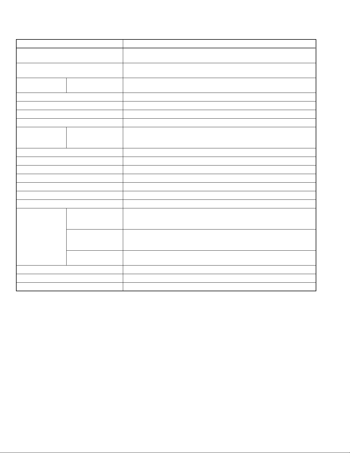
SPECIFICATION
Item Contents
Dimensions (W × H × D) 54.1cm × 41.6cm × 9.2cm (TV only)
43.1cm × 47.7cm × 22.5cm (Included Stand)
Mass 9.6kg (TV only)
13.8kg (Included Stand)
Power Input TV
AC Adapter
Power Consumption 60W (Stand-by : 1W)
TV RF System CCIR B/G I D/K L
Color System PAL / SECAM / NTSC3.58 / NTSC4.43
Stereo System A2 (B/G D/K) NICAM (B/G I D/K L)
Frequency Receiving French cable TV 46.25MHz ~ 862.25MHz
Teletext System FLOF (Fastext) TOP WST (World Standard System)
LCD Panel 20.1V wide aspect (4 : 3)
Screen Size Diagonal : 51.0cm (H : 40.8cm × V : 30.6cm)
Display Pixels Horizontal : 640 pixels × Vertical : 480 pixels
Audio Power Output 3W + 3W
Speaker 5.0cm × 3.8cm × 2.0cm box type × 2
Aerial Terminal 75Ω unbalanced coaxial
External terminal [EXT-1] (Input / Output) 21 pin Euro connector (SCART socket)
[EXT-2] (Input / Output) 21 pin Euro connector (SCART socket)
[EXT-3] (Input) RCA pin jack x 3 S-VIDEO connector x 1
Headphone 3.5mm mini jack × 1
Remote Control Unit RM-C1861 (AA/R6 battery × 2)
AC Adapter DA-E061370334
DC 12V
AC 100V ~ AC 240V, 50Hz / 60Hz
116MHz ~ 172MHz
220MHz ~ 469MHz
• Video input Audio L/R inputs and RGB inputs are available.
• TV broadcast outputs (Video and Audio L/R) are available.
• Video input S-VIDEO (Y/C) input Audio L/R inputs and RGB inputs are available.
• Video and Audio L/R outputs are available.
• Video input S-VIDEO(Y/C) and Audio L/R inputs are available.
NOTE : Design & specifications are subject to change without notice.
1-2 (No.YA436)
Page 3
SECTION 1
PRECAUTION
1.1 SAFETY PRECAUTIONS
(1) The design of this product contains special hardware,
many circuits and components specially for safety
purposes. For continued protection, no changes should be
made to the original design unless authorized in writing by
the manufacturer. Replacement parts must be identical to
those used in the original circuits. Service should be
performed by qualified personnel only.
(2) Alterations of the design or circuitry of the products should
not be made. Any design alterations or additions will void
the manufacturer's warranty and will further relieve the
manufacturer of responsibility for personal injury or
property damage resulting therefrom.
(3) Many electrical and mechanical parts in the products have
special safety-related characteristics. These characteristics
are often not evident from visual inspection nor can the
protection afforded by them necessarily be obtained by
using replacement components rated for higher voltage,
wattage, etc. Replacement parts which have these special
safety characteristics are identified in the parts list of
Service manual. Electrical components having such
features are identified by shading on the schematics
and by ( ) on the parts list in Service manual. The use
of a substitute replacement which does not have the same
safety characteristics as the recommended replacement
part shown in the parts list of Service manual may cause
shock, fire, or other hazards.
(4) Don't short between the LIVE side ground and
ISOLATED (NEUTRAL) side ground or EARTH side
ground when repairing.
Some model's power circuit is partly different in the GND.
The difference of the GND is shown by the LIVE : ( ) side
GND, the ISOLATED (NEUTRAL) : ( ) side GND and
EARTH : ( ) side GND.
Don't short between the LIVE side GND and ISOLATED
(NEUTRAL) side GND or EARTH side GND and never
measure the LIVE side GND and ISOLATED (NEUTRAL)
side GND or EARTH side GND at the same time with a
measuring apparatus (oscilloscope etc.). If above note will
not be kept, a fuse or any parts will be broken.
(5) If any repair has been made to the chassis, it is
recommended that the B1 setting should be checked or
adjusted (See ADJUSTMENT OF B1 POWER SUPPLY).
(6) The high voltage applied to the picture tube must conform
with that specified in Service manual. Excessive high
voltage can cause an increase in X-Ray emission, arcing
and possible component damage, therefore operation under
excessive high voltage conditions should be kept to a
minimum, or should be prevented. If severe arcing occurs,
remove the AC power immediately and determine the cause
by visual inspection (incorrect installation, cracked or melted
high voltage harness, poor soldering, etc.). To maintain the
proper minimum level of soft X-Ray emission, components
in the high voltage circuitry including the picture tube must
be the exact replacements or alternatives approved by the
manufacturer of the complete product.
(7) Do not check high voltage by drawing an arc. Use a high
voltage meter or a high voltage probe with a VTVM.
Discharge the picture tube before attempting meter
connection, by connecting a clip lead to the ground frame
and connecting the other end of the lead through a 10kΩ
2W resistor to the anode button.
(8) When service is required, observe the original lead dress.
Extra precaution should be given to assure correct lead
dress in the high voltage circuit area. Where a short circuit
has occurred, those components that indicate evidence of
overheating should be replaced. Always use the manufacturer's replacement components.
(9) Isolation Check (Safety for Electrical Shock Hazard)
After re-assembling the product, always perform an
isolation check on the exposed metal parts of the cabinet
(antenna terminals, video/audio input and output terminals,
Control knobs, metal cabinet, screw heads, earphone jack,
control shafts, etc.) to be sure the product is safe to operate
without danger of electrical shock.
a) Dielectric Strength Test
The isolation between the AC primary circuit and all metal
parts exposed to the user, particularly any exposed metal
part having a return path to the chassis should withstand a
voltage of 3000V AC (r.m.s.) for a period of one second. (.
. . . Withstand a voltage of 1100V AC (r.m.s.) to an
appliance rated up to 120V, and 3000V AC (r.m.s.) to an
appliance rated 200V or more, for a period of one second.)
This method of test requires a test equipment not generally
found in the service trade.
b) Leakage Current Check
Plug the AC line cord directly into the AC outlet (do not use
a line isolation transformer during this check.). Using a
"Leakage Current Tester", measure the leakage current
from each exposed metal part of the cabinet, particularly
any exposed metal part having a return path to the chassis,
to a known good earth ground (water pipe, etc.). Any
leakage current must not exceed 0.5mA AC (r.m.s.).
However, in tropical area, this must not exceed 0.2mA AC
(r.m.s.).
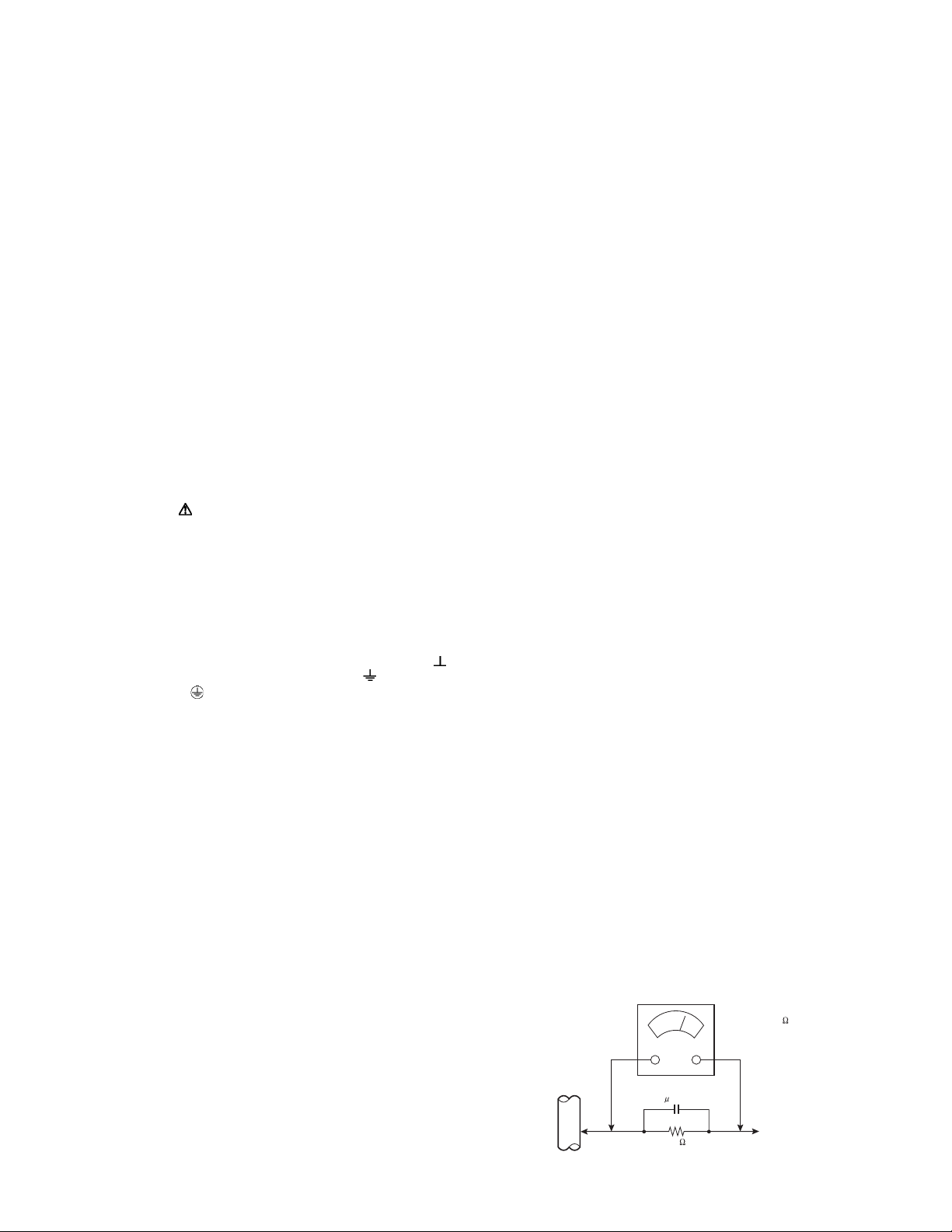
Alternate Check Method
Plug the AC line cord directly into the AC outlet (do not
use a line isolation transformer during this check.). Use
an AC voltmeter having 1000Ω per volt or more
sensitivity in the following manner. Connect a 1500Ω
10W resistor paralleled by a 0.15µF AC-type capacitor
between an exposed metal part and a known good earth
ground (water pipe, etc.). Measure the AC voltage
across the resistor with the AC voltmeter. Move the
resistor connection to each exposed metal part,
particularly any exposed metal part having a return path
to the chassis, and measure the AC voltage across the
resistor. Now, reverse the plug in the AC outlet and
repeat each measurement. Any voltage measured must
not exceed 0.75V AC (r.m.s.). This corresponds to
0.5mA AC (r.m.s.).
However, in tropical area, this must not exceed 0.3V AC
(r.m.s.). This corresponds to 0.2mA AC (r.m.s.).
AC VOLTMETER
(HAVING 1000 /V,
OR MORE SENSITIVITY)
0.15 F AC-TYPE
PLACE THIS PROBE
1500 10W
GOOD EARTH GROUND
ON EACH EXPOSED
ME TAL PAR T
(No.YA436)1-3
Page 4
1.2 INSTALLATION
1.2.1 HEAT DISSIPATION
If the heat dissipation vent behind this unit is blocked, cooling efficiency may deteriorate and temperature inside the unit will rise.
Therefore, please make sure pay attention not to block the heat dissipation vent as well as the ventilation outlet behind the unit and
ensure that there is room for ventilation around it.
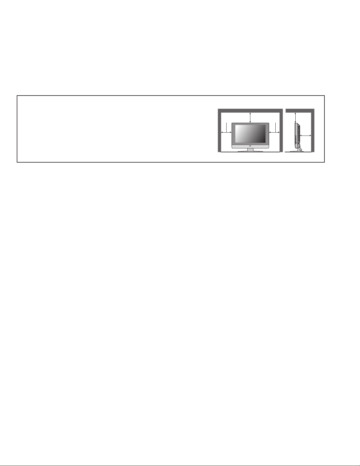
1.2.2 INSTALLATION REQUIREMENTS
Ensure that the minimal distance is maintained, as specified below, between the unit with and the surrounding walls.
Install the unit on stable flooring or stands.
Take precautionary measures to prevent the unit from tipping in order to protect against accidents and earthquakes.
Distance recommendations
Avoid improper installation and never position the unit where good ventilation
is impossible.
When installing this TV, distance recommendations must be maintained
between the set and the wall, as well as inside a tightly enclosed area or
150 mm
200 mm 200 mm
150 mm
50 mm
piece of furniture.
Keep to the minimum distance guidelines shown for safe operation.
1.3 PRECAUTIONS
(1) The picture brightness may become uneven on the entire screen according to the environmental temperature. Be sure to use
your monitor set in a specified temperature range for proper display presentation.
(2) Avoid disturbing the heat dissipation from the vent holes provided in the rear, on the top and at the sides. Failure to do so may
result in damaged electronics inside due to the accumulated heat within the unit.
(3) Be sure to install the unit in a well-ventilated place. Also make sure that the ambient temperature is kept in the range of 0 to 35°C.
(4) Avoid operation or storage in high temperature and humidity that exceed the specified limit. Otherwise, the display presentation
may be deteriorated.
(5) This monitor may display a blurred picture when exposed to an extreme environmental conditions. This phenomenon is due to
an intrinsic characteristic of the Liquid Crystal Display (LCD). This is not the failure.
(6) This monitor display uses a Cold Cathode Tube as a backlighting device. The brilliance of this tube (and the monitor display)
may be degraded by time.
1.4 CAUTIONS FOR TRANSPORTATION
The goods may be damaged during transportation caused by poor handling such as throwing, toppling, dropping, etc, giving an excess
force against the LCD device. This may happen even if the packing is rigid and secured. To avoid such adverse situations, give a
proper instruction to the freighter for secured handling. The LCD panel uses a glass plate, which is very fragile against an external
force. Take utmost care to avoid vibration or shock to the panel.
1-4 (No.YA436)
Page 5

SECTION 2
SPECIFIC SERVICE INSTRUCTIONS
2.1 ABOUT LIQUID CRYSTAL DISPLAY
2.1.1 STRUCTURE OF LIQUID CRYSTAL PANEL
The Liquid Crystal Display used for this unit is of a TFT (Thin Film Transistor) type panel. The structure of this panel is that a TFT
array-formed substrate and the stripe pixel matrix type color filter substrate are pressed together with a liquid crystal filled in between
these materials.
2.1.2 LONG-TERM AFTERIMAGE ON THE LCD
A minute amount of ionic material could be mingled into a liquid crystal substrate in the manufacturing process. By applying the
electricity to the panel the ionic material may be migrated towards one part of the electrodes, causing a long-term afterimage to be
displayed. In practice, when a still image is displayed for a long time, the afterimage may be developed and persisted. To cure this
problem, turn off the unit and then turn on again and arrange displaying an appropriate still image on the portion where the afterimage
is being superimposed.
2.1.3 RESPONSE SPEED OF THE LCD
The LCD is slower than the CRT in terms of the display refresh rate, causing a fast moving picture may be displayed blurred. This is
not fault but caused by an intrinsic characteristic of the LCD.
2.1.4 VIEWING ANGLE OF THE LCD
This LCD uses a wide-angle liquid crystal panel, featuring a low rate of the brightness inversion. When viewed from a far outer angle,
the screen may be displayed with hue variation. Again, this is not fault but caused by an intrinsic characteristic of the LCD.
2.1.5 PIXEL DEFICIENCY OF THE LCD
The liquid crystal panel is manufactured with precise engineering procedure. However, there is a possibility of yielding a little amount
of defective pixels in part on the panel. This is unavoidable feature even if the latest technology is being used for manufacturing the
LCD module.
2.2 IMPORTANT NOTICE WHEN REPLACING COMPONENT PARTS
2.2.1 REPLACING THE LCD MODULE
(1) The LCD panel is fragile against the static charge. Be sure to take an appropriate grounding using a grounding-strap etc. when
to replace the LCD panel.
(2) The LCD is made of glass, which is fragile against the mechanical shock. Use utmost care when handling the LCD panel.
(3) When replacing the panel, first place the panel on the base chassis and then make sure that there is no gap in between the panel
and the chassis. Fix the panel with fixing screws. Turn the unit on with an all-black signal being put in and check if the brightness
is even on the entire screen. If the brightness is not even in some part, slacken the fixing screw nearby until the brightness
becomes even with other parts.
(4) A tightening torque for the fixing screws must be set to 0.294Nm or the less. Applying the torque larger than this limit may result
in the damage on the LCD panel.
(5) Connecting or disconnecting the plugs with the set is being powered may cause the malfunction of the set. Makes sure that the
AC power plug is disconnected from the power source when attempting the replacement work.
2.2.2 REPLACING THE FUSE
Be sure to use the rated fuse. After replacing the fuse, confirm that the insulator is stuck on the shielding surface for secure insulation.
(No.YA436)1-5
Page 6
SECTION 3
DISASSEMBLY
3.1 DISASSEMBLY PROCEDURE
CAUTION AT DISASSEMBLY:
• Be sure to perform the SYSTEM SETTEING, at the end of
the procedure.
• Make sure that the power cord is disconnected from the outlet.
• Pay special attention not to break or damage the parts.
• When removing each board, remove the connectors as required.
Taking notes of the connecting points (connector numbers)
makes service procedure manageable.
• Make sure that there is no bent or stain on the connectors
before inserting, and firmly insert the connectors.
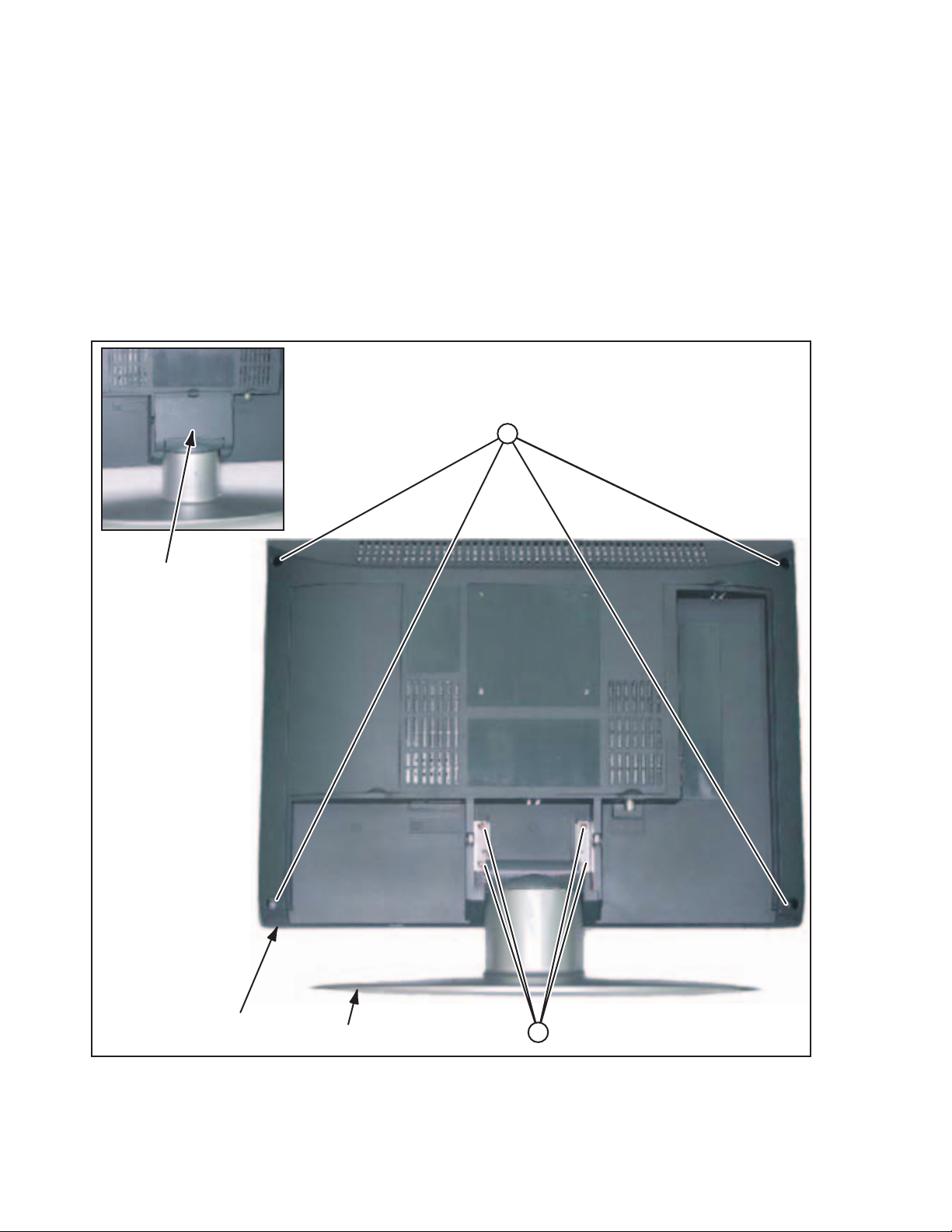
3.1.1 REMOVING THE STAND ASS'Y (Fig.1)
(1) Remove the HINGE COVER.
(2) Remove the 4 screws [A], then remove the STAND ASS'Y.
3.1.2 REMOVING THE REAR COVER (Fig.1)
• Remove the STAND ASS'Y.
(1) Remove the 4 screws [B], then remove the REAR COVER.
CAUTION:
• For the REAR COVER is attached tightly, it is easy to open
from the corner of the REAR COVER.
B
HINGE COVER
REAR COVER
STAND ASS'Y
A
1-6 (No.YA436)
Fig.1
Page 7
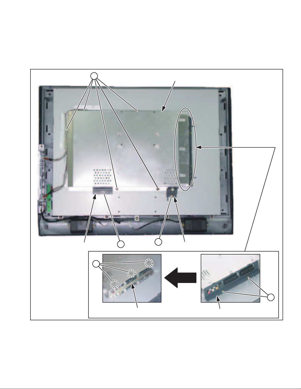
3.1.3 REMOVING THE MAIN PWB SHIELD (Fig.2)
• Remove the STAND ASS'Y.
• Remove the REAR COVER.
(1) Remove the 1 screw [C], then remove the D-SUB COVER.
(1) Remove the 1 screw [D], then remove the TUNER COVER.
(1) Remove the 2 screws [E], then remove the AV COVER.
(1) Remove the 3 claws [F], then remove the MAIN PWB SIDE SHIELD.
(1) Remove the 5 screws [G], then remove the MAIN PWB SHIELD.
G
MAIN PWB SHIELD
D-SUB COVER
F
C
D
MAIN PWB SIDE SHIELD
Fig.2
TUNER COVER
E
AV COVER
(No.YA436)1-7
Page 8
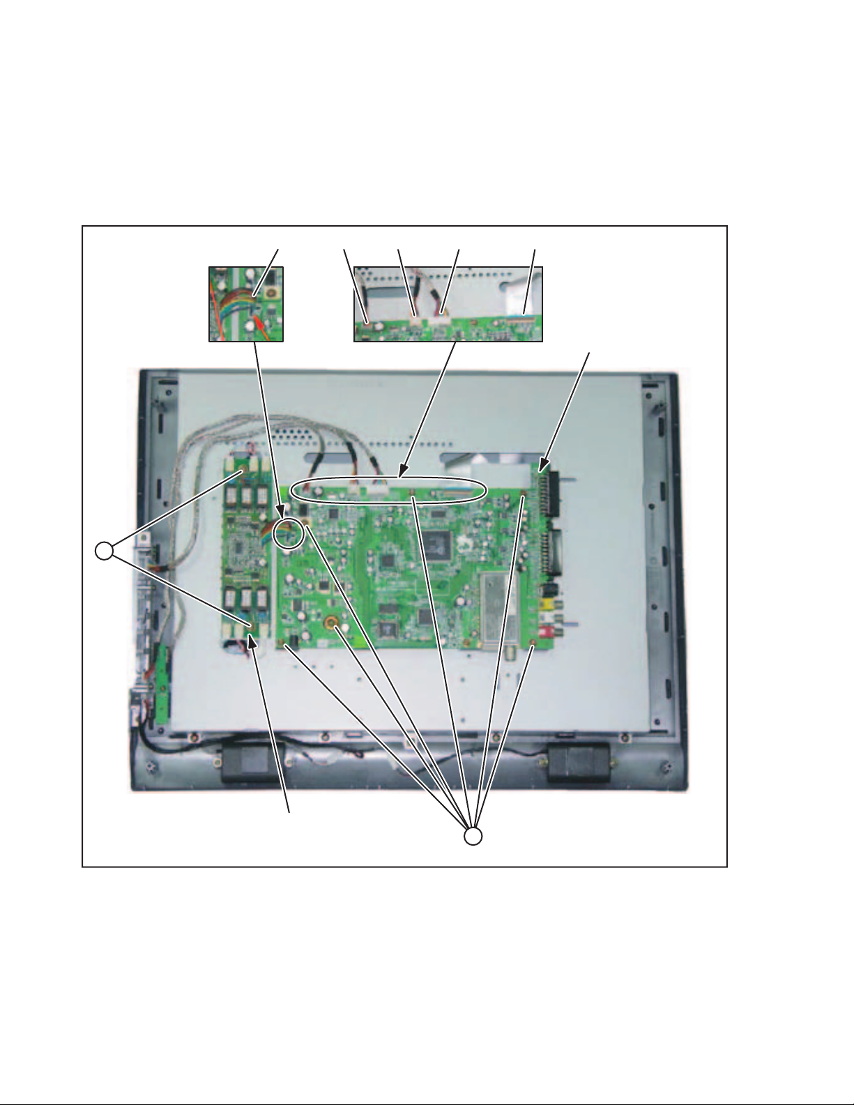
3.1.4 REMOVING THE MAIN PWB (Fig.3)
• Remove the STAND ASS'Y.
• Remove the REAR COVER.
• Remove the MAIN PWB SHIELD.
(1) Disconnect the connectors [P001], [P004], [P006], [P009],
[P012] from the MAIN PWB.
(2) Remove the 6 screws [H], then remove the MAIN PWB.
NOTE:
• It is advisable to take note of the connecting location (connector
number) of the removed connectors.
3.1.5 REMOVING THE INVERTER PWB (Fig.3)
• Remove the STAND ASS'Y.
• Remove the REAR COVER.
• Remove the MAIN PWB SHIELD.
(1) Disconnect the connectors from the INVERTER PWB.
(2) Disconnect the connector from the MAIN PWB.
(3) Remove the 2 screws [J], then remove the INVERTER PWB.
NOTE:
• It is advisable to take note of the connecting location (connector
number) of the removed connectors.
[P001][P006][P009][P012][P004]
MAIN PWB
J
INVERTER PWB
H
Fig.3
1-8 (No.YA436)
Page 9
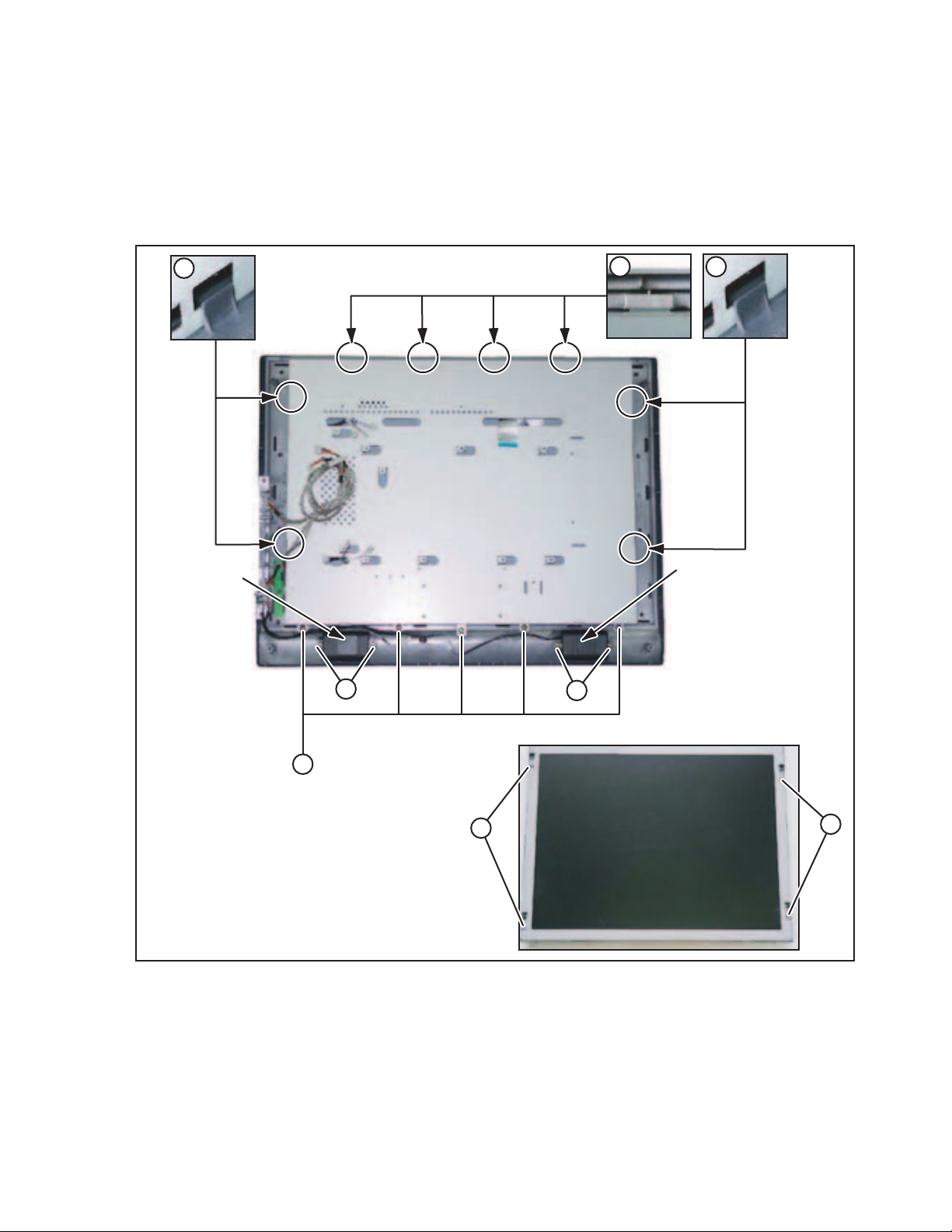
3.1.6 REMOVING THE LCD PANEL UNIT (Fig.4)
• Remove the STAND ASS'Y.
• Remove the REAR COVER.
• Remove the MAIN PWB SHIELD.
• Remove the MAIN PWB.
• Remove the INVERTER PWB.
(1) Remove the 5 screws [K].
(2) Remove the 2 claws [L], 2 claws [M] and 4 claws [N], then
remove the LCD PANEL UNIT and LCD BRACKET.
(3) Remove the 4 screws [P], then remove the LCD PANEL UNIT.
3.1.7 REMOVING THE SPEAKER (Fig.4)
• Remove the STAND ASS'Y.
• Remove the REAR COVER.
(1) Disconnect the connectors from the KEY PWB.
(2) Remove the 4 screws [Q], then remove the SPEAKER (L/R).
NOTE:
• It is advisable to take note of the connecting location (con-
nector number) of the removed connectors.
L
SPEAKER
N
Q
Q
M
SPEAKER
[FRONT SIDE]
K
P
P
Fig.4
(No.YA436)1-9
Page 10
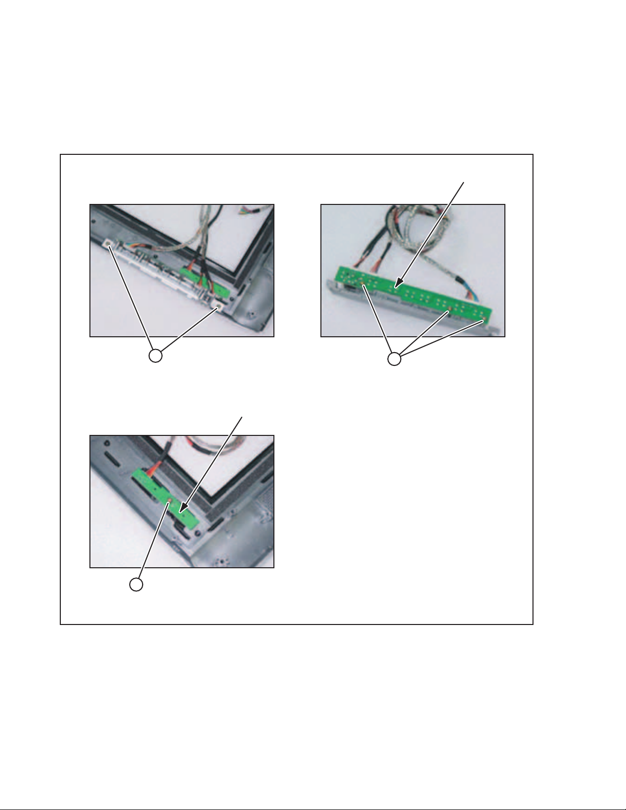
3.1.8 REMOVING THE KEY PWB (Fig.5)
• Remove the STAND ASS'Y.
• Remove the REAR COVER.
(1) Disconnect the connectors from the KEY PWB.
(2) Remove the 2 screws [R] and 3 screws [S], then remove
the KEY PWB.
NOTE:
• It is advisable to take note of the connecting location (connector
number) of the removed connectors.
3.1.9 REMOVING THE IR PWB (Fig.5)
• Remove the STAND ASS'Y.
• Remove the REAR COVER.
(1) Disconnect the connectors from the IR PWB.
(2) Remove the 1 screw [T], then remove the IR PWB.
NOTE:
• It is advisable to take note of the connecting location (con-
nector number) of the removed connectors.
KEY PWB
R
IR PWB
T
S
Fig.5
1-10 (No.YA436)
Page 11
3.2 REPLACEMENT OF CHIP COMPONENT
3.2.1 CAUTIONS
(1) Avoid heating for more than 3 seconds.
(2) Do not rub the electrodes and the resist parts of the pattern.
(3) When removing a chip part, melt the solder adequately.
(4) Do not reuse a chip part after removing it.
3.2.2 SOLDERING IRON
(1) Use a high insulation soldering iron with a thin pointed end of it.
(2) A 30w soldering iron is recommended for easily removing parts.
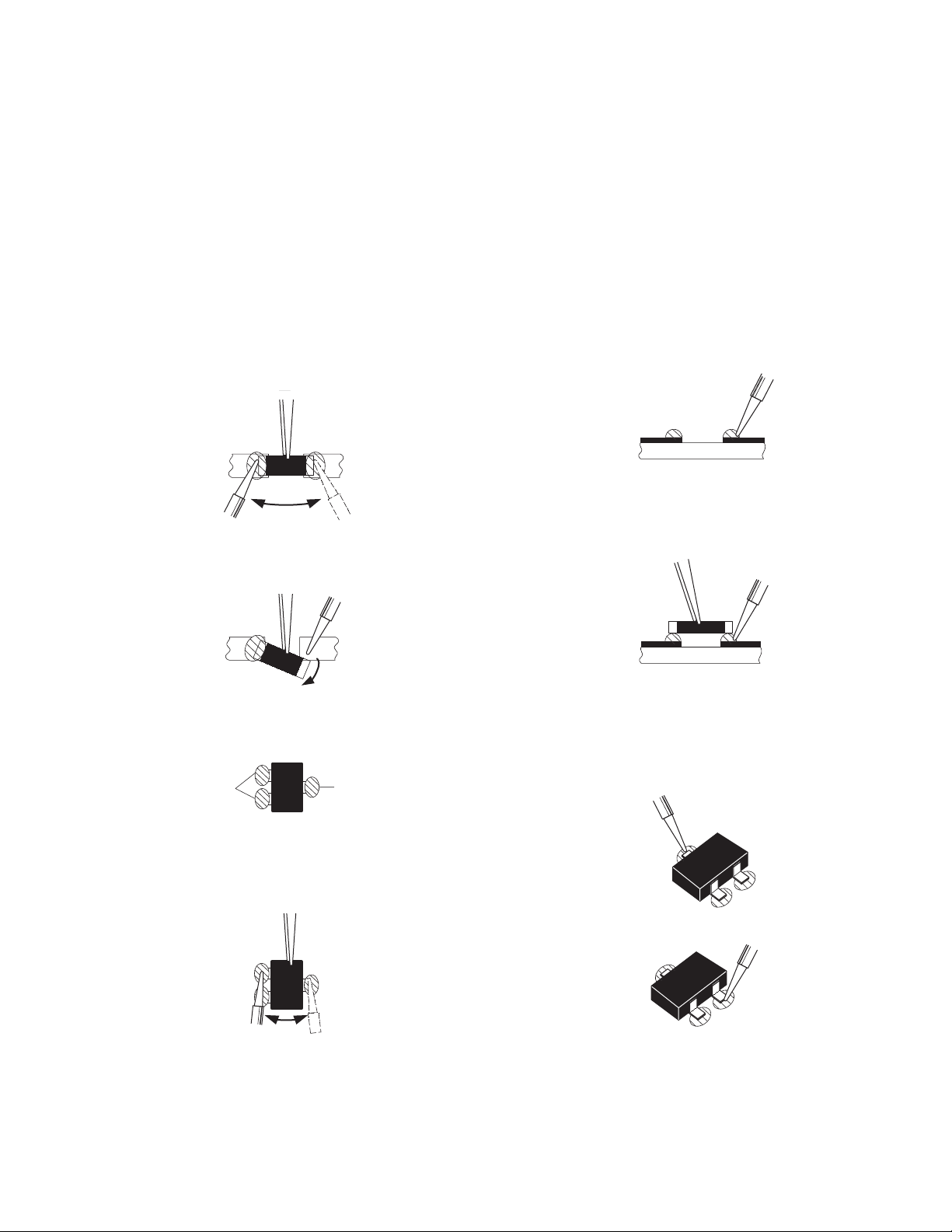
3.2.3 REPLACEMENT STEPS
1. How to remove Chip parts
2. How to install Chip parts
[Resistors, capacitors, etc.]
(1) As shown in the figure, push the part with tweezers and
alternately melt the solder at each end.
(2) Shift with the tweezers and remove the chip part.
[Transistors, diodes, variable resistors, etc.]
(1) Apply extra solder to each lead.
SOLDER
SOLDER
[Resistors, capacitors, etc.]
(1) Apply solder to the pattern as indicated in the figure.
(2) Grasp the chip part with tweezers and place it on the
solder. Then heat and melt the solder at both ends of the
chip part.
[Transistors, diodes, variable resistors, etc.]
(1) Apply solder to the pattern as indicated in the figure.
(2) Grasp the chip part with tweezers and place it on the
solder.
(3) First solder lead A as indicated in the figure.
(2) As shown in the figure, push the part with tweezers and
alternately melt the solder at each lead. Shift and remove
the chip part.
NOTE :
After removing the part, remove remaining solder from the
pattern.
A
B
C
(4) Then solder leads B and C.
A
B
C
(No.YA436)1-11
Page 12

SECTION 4
ADJUSTMENT
This service manual does not describe ADJUSTMENT.
1-12 (No.YA436)
Page 13
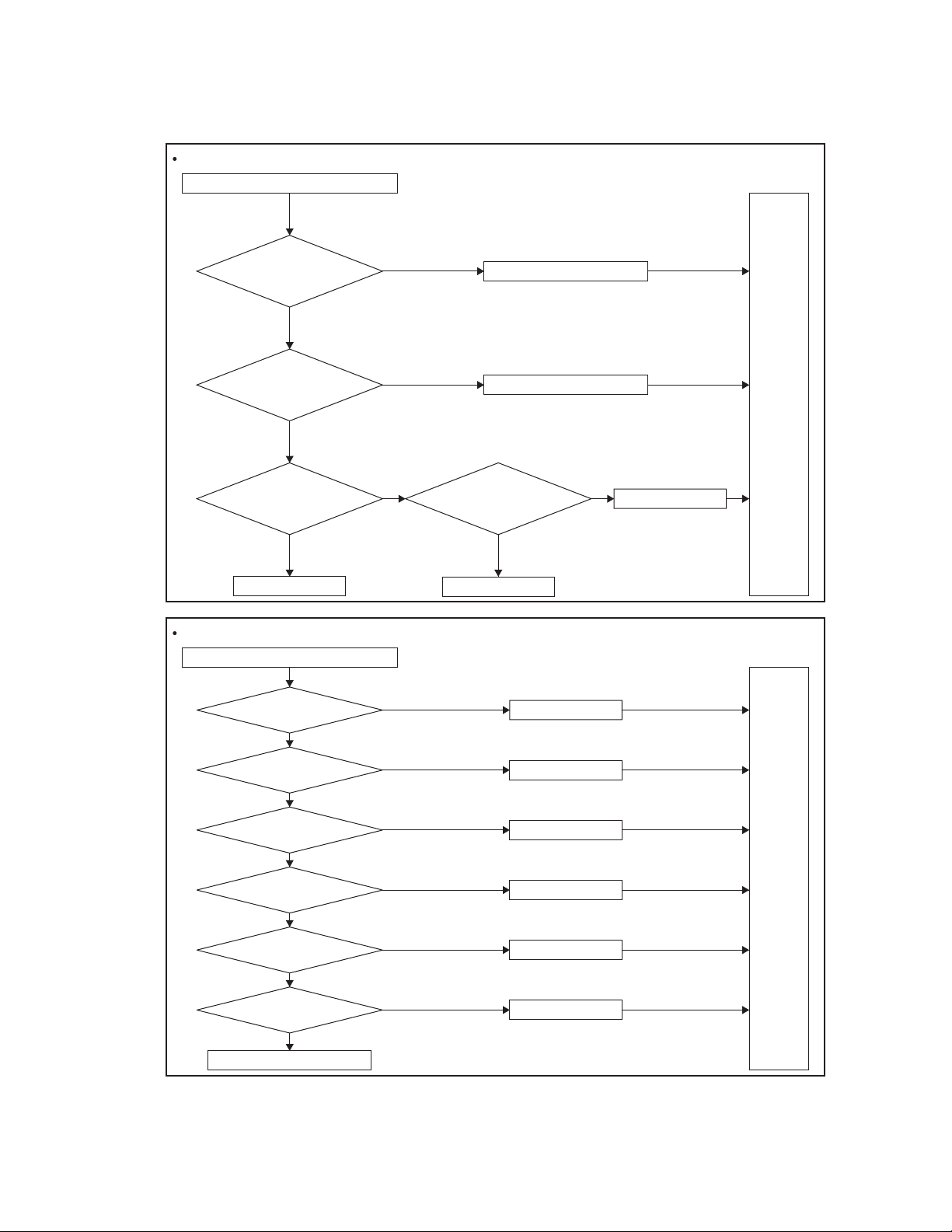
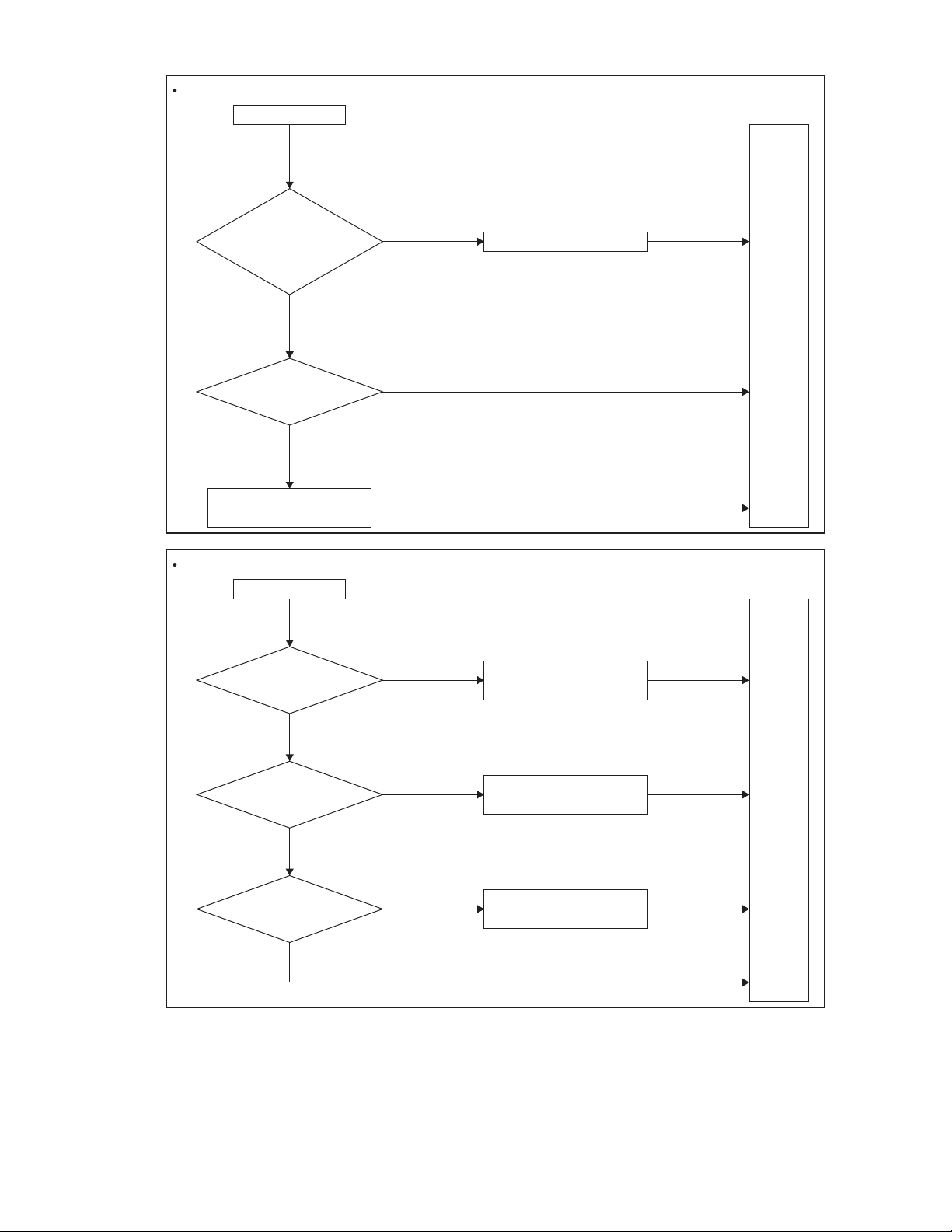
Power Turn On Issue
Power cannot be turn on (LED does not light)
SECTION 5
TROUBLESHOOTING
Check if the Power
Cord has been well
connected to AC
adapter
Is the input voltage DC
12V applied M-PCB
Voltage of I008 Pin#2 is
Change I013
No Picture
Picture is not shown on screen
Check 5V_VCC voltage
on I002 Pin#5~8
Check EX-VD3_3
voltage on I009 Pin#2
Check EX-VL1.8 voltage
on I004 Pin#2
Check EX-VD1.8 voltage
on I003 Pin#2
Check TTL output signal
Check if FPC cable loose
5V
of I031
YES
YES
YES
YES
YES
YES
YES
NO
NO
NO NO
NO
NO
NO
NO
NO
NO
Connect the connector properly
Change AC adapter
Check if waveform
of I008 Pin#2 is
normal
YES
Change I008
Change I002
Change I009
Change I009
Change I003
Change I031
Change Panel
Test
again
Change D003 & I008
Test
again
YES
Reconnect FPC cable well
(No.YA436)1-13
Page 14
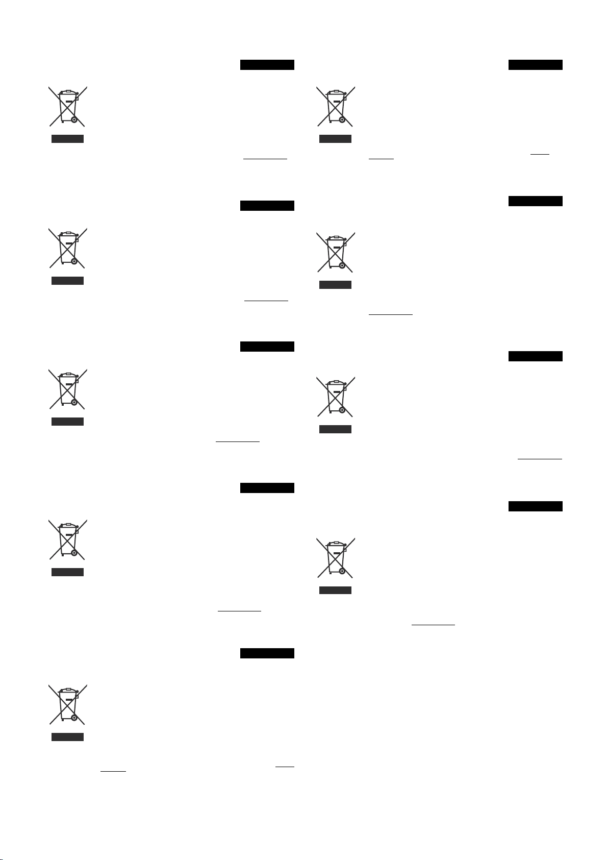
No sound
Picture is displayed. But no sound
Take off the
back cover and check if
wires of the speakers terminals have
been well connected to the
PCB-Main and Speakers?
YES
NO
Connect the wires properly
Check if the I/P signals
applied to I033 audio
processor
YES
Are there signals on the
speaker terminals?
YES
Speakers
NO
NO
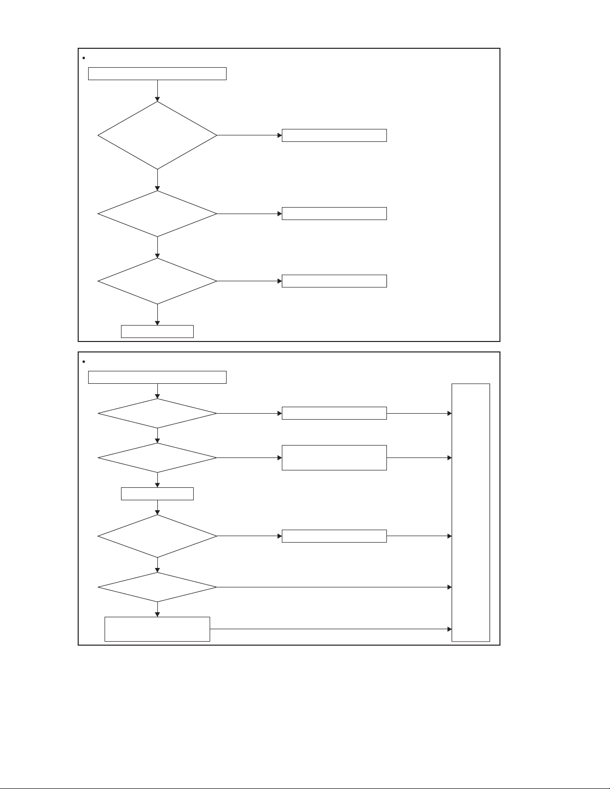
Remote Control doesn't Work
Remote controller doesn't work
Try if another Remote
Controller works?
NO
Check if batteries are
placed correctly?
YES
Take off the back cover.
Check if the wire of
PCB-IR has been well
connected to the
PCB-Main?
YES
Change the PCB-IR then
check if it works.
NO
Change PCB-Main then
connect all wires properly.
YES
NO
NO
YES
Check I/O input circuit
PCB-Speaker Connector
Replace the Remote Controller.
Put new batteries to
the remote control
Test
again
Connect the wire properly.
1-14 (No.YA436)
Page 15
Key Pad doesn't Work
Key pad doesn't work
Take off the
back cover and check
if the wire of PCB-Key Pad has well
connected to the PCB-Main?
YES
Change PCB-Key Pad
and connect all wires
properly. Check if it
works.
NO
Change the PCB-Main
NO
YES
No Signal Issue (SACRT, AV, SV)
No signal
Check if the signal
source is available and been
well connected?
NO
Connect the wire properly
Test
again
Enable source and connect
the signal wire properly.
YES
Check if the PCB-I/O
circuit input waveform
is OK
YES
Check Video
switched
(I022,I007,I029,I026,I020)
In/output waveform
YES
NO
NO
Check if any component
missing or poor soldering
Check if any poor soldering or
component missing of the
video switch related circuit
Test
again
(No.YA436)1-15
Page 16

Victor Company of Japan, Limited
Display Category 12, 3-chome, Moriya-cho, Kanagawa-ku, Yokohama-city, Kanagawa-prefecture, 221-8528, Japan
(No.YA436)
Printed in Japan
VPT
Page 17

LCT1923-002A-U
0505KTH-AL-MU
Information for Users on Disposal of Old Equipment
ENGLISH
[European Union]
Attention:
This symbol is only
valid in the European
Union.
This symbol indicates that the electrical and electronic equipment should not be disposed as
general household waste at its end-of-life. Instead, the product should be handed over to the
applicable collection point for the recycling of electrical and electronic equipment for proper
treatment, recovery and recycling in accordance with your national legislation.
By disposing of this product correctly, you will help to conserve natural resources and will
help prevent potential negative effects on the environment and human health which could
otherwise be caused by inappropriate waste handling of this product. For more information
about collection point and recycling of this product, please contact your local municipal
office, your household waste disposal service or the shop where you purchased the product.
Penalties may be applicable for incorrect disposal of this waste, in accordance with national
legislation.
(Business users)
If you wish to dispose of this product, please visit our web page www.jvc-europe.com
to
obtain information about the ta ke-back of the product.
[Other Countries outside the European Union]
If you wish to dispose of this product, please do so in accordance with applicable national
legislation or other rules in your cou ntry for the treatment of old electrical and electronic
equipment.
Benutzerinformationen zur Entsorgung alter Geräte
DEUTSCH
[Europäische Union]
Hinweis:
Dieses Symbol ist nur
in der Europäischen
Union gültig.
Dieses Symbol zeigt an, dass das elektrische bzw. elektronische Gerät nicht als n ormaler
Haushaltsabfall entsorgt werden soll. Stattdessen sollte da s Produkt zur fachgerechten
Entsorgung, Weiterverwendung und Wiederverwertung in Übereinstimmung mit der
Landesgesetzgebung einer entsprechenden Sammelstell e für das Recycling elektrischer
und elektronischer Geräte zugeführt werden.
Die korrekte Entsorgung dieses Produkts dient dem Umweltschutz und verhindert mögliche
Schäden für die Umwelt und die menschliche Gesundheit, welche durch unsachgemäße
Behandlung des Produkts auftreten können. Weitere Informationen zu Sammelstellen und
dem Recycling dieses Produkts erhalten Sie bei Ihrer Geme indeverwaltung, Ihrem örtlichen
Entsorgungsunternehmen oder in dem Geschäf t, in dem Sie das Produkt gekauft haben.
Für die nicht fachgerechte Entsorgung dieses Abfalls können gemäß der
Landesgesetzgebung Strafen ausgesprochen werden.
(Geschäftskunden)
Wenn Sie dieses Produkt entsorgen möchten, besuc hen Sie bitte unsere Webseite www.jvceurope.com
, um Informationen zur Rücknahme des Produkts zu erhalten.
[Andere Länder außerhalb der Europäischen Union]
Wenn Sie dieses Produkt entsorgen möchten, hal ten Sie sich dabei bitte an die
entsprechenden Landesgesetze und andere Regelungen in Ihrem Land zur Behandlung
elektrischer und elektronischer Geräte.
Informations relatives à l’élimination des appareils usagés, à
l’intention des utilisateurs
FRANÇAIS
[Union européenne]
Attention :
Ce symbole n’est
reconnu que dans
l’Union européenne.
Lorsque ce symbole figure sur un appareil électrique et électronique, cela signifie qu’il ne
doit pas être éliminé en tant que déchet ménager à la fin de son cycle de vie. Le produit doit
être porté au point de pré-collecte appr oprié au recyclage des appareils électriques et
électroniques pour y subir un traitement, une récupération et un recyclage, conformément à
la législation nationale.
En éliminant correctement ce produit, vous contriburez à la con servation des ressources
naturelles et à la prévention des éventuels effets négatifs sur l’environnement et la santé
humaine, pouvant être dus à la manipulation inappropriée des dé chets de ce produit. Pour
plus d’informations sur le point de pré-collecte et le recycl age de ce produit, contactez votre
mairie, le service d’évacuation des ordures ménagères o u le magasin dans lequel vous avez
acheté le produit.
Des amendes peuvent être infligées en cas d’élimination incorrecte de ce produit,
conformément à la législation nationale.
(Utilisateurs professionnels)
Si vous souhaitez éliminer ce produit, visitez notre page Web www.jvc-europe.com
afin
d’obtenir des informations sur sa récupération.
[Pays ne faisant pas partie de l’Union européenne]
Si vous souhaitez éliminer ce produit, faites-le conformément à la législation nationale ou
autres règles en vigueur dans votre pays pour le traitement des appareils éle ctriques et
électroniques usagés.
Informatie voor gebruikers over het weggooien van oude
apparatuur
NEDERLANDS
[Europese Unie]
Let op:
Dit symbool is alleen
geldig in de Europese
Unie.
Deze markering geeft aan dat de elektrische en elektronische apparatuur bij het einde van
de gebruiksduur niet bij het huishoudelijk afval mag worden gegooid. Het product moet in
plaats daarvan worden ingeleverd bij het relevante inzamelingspunt voor hergebruik van
elektrische en elektronische apparatuur, voor juiste verwerking, terugwi nning en hergebruik
in overeenstemming met uw nationale wetgeving.
Door dit product naar het inzamelingspunt te brenge n, werkt u mee aan het behoud van
natuurlijke hulpbronnen en met het voorkomen van potentiële negatieve effecten op het
milieu en de volksgezondheid, die anders veroorzaakt zouden kunnen worden door onjuiste
afvalverwerking van dit product. Neem voor meer informatie over inzamelingspunten en
hergebruik van dit product contact op met de gemeente in uw woonplaats, het
afvalverwerkingsbedrijf of de winkel waar u het product hebt aangeschaft .
Er kunnen boetes gelden voor een onjuiste verwijdering van dit afval, in overeenstemming
met de nationale wetgeving.
(Zakelijke gebruikers)
Bezoek als u dit product wilt weggooien onze website www.jvc-europe.com
voor informatie
over het terugnemen van het product.
[Landen buiten de Europese Unie]
Wanneer u dit product wilt verwijderen, houdt u dan aan de geldende nationale wetgeving of
andere regels in uw land voor de verwerking van oude elektri sche en elektronische
apparatuur.
Información para los usuarios sobre la eliminación de equipos
usados
CASTELLANO
[Unión Europea]
Atención:
Este símbolo sólo es
válido en la Unión
Europea.
Este símbolo indica que los aparatos eléctricos y el ectrónicos no deben desecharse junto
con la basura doméstica al final de su vida útil. El producto deberá llevarse al punto de
recogida correspondiente para el reciclaje y el t ratamiento adecuado de equipos eléctricos y
electrónicos de conformidad con la legislación nacional.
Si desecha el producto correctamente, estará contribuyendo a conservar los recursos
naturales y a prevenir los posibles efectos negativos en el medio ambiente y en la salud de
las personas que podría causar el tratamiento ina decuado del producto desechado. Para
obtener más información sobre el punto de recogida y el reciclaje de este producto, póngase
en contacto con su oficina municipal, su ser vicio de recogida de basura doméstica o la
tienda en la que haya adquirido el producto.
De acuerdo con la legislación nacional, podrí an aplicarse multas por la eliminación
incorrecta de estos desechos.
(Empresas)
Si desea desechar este producto, visite nuestra página Web www.jvc-europe.com
para
obtener información acerca de la retirada del producto.
[Otros países no pertenecientes a la Unión Europea]
Si desea desechar este producto, hágalo de conformidad con la legi slación nacional vigente
u otras normativas de su país para el tratamiento de equipos eléctr icos y electrónicos
usados.
Informazioni per gli utenti sullo smaltimento delle apparecchiature
obsolete
ITALIANO
[Unione Europea]
Attenzione:
Questo simbolo è
valido solo nell'Unione
Europea.
Questo simbolo indica che l’apparecchiatura elett rica ed elettronica a cui è relativo non deve
essere smaltita tra i rifiuti domestici generici alla fine della sua vita utile. Il prodotto, invece,
va consegnato a un punto di raccolta appropriato per il ri ciclaggio di apparecchiature
elettriche ed elettroniche, per il trattamento, il recupero e il r iciclaggio corretti, in conformità
alle proprie normative nazionali.
Mediante lo smaltimento corretto di questo prodotto, si contribuirà a preservare le risorse
naturali e a prevenire potenziali effetti negativi sull'ambiente e sulla salute umana che
potrebbero essere provocati, altrimenti, da uno smaltimento inappropriato del prodotto. Per
ulteriori informazioni sul punto di raccolta e il riciclaggio di questo prodotto, contattare la
sede comunale locale, il servizio di smaltimento rifiuti domestici o il negozio in cui si è
acquistato il prodotto.
L’utente è responsabile del conferimento dell’apparecc hio a fina vita alle appropriate
strutture di raccolta, pena le sanzioni previste dalla vige nte legislazione sui rifiuti.
(Per gli utenti aziendali)
Qualora si desideri smaltire questo prodotto, visitare la nostra pagi na web www.jvc-
europe.com
per ottenere informazioni sul ritiro del prodotto.
[Per altre nazioni al di fuori dell'Unione Europea]
Qualora si desideri smaltire questo prodotto, effettuare lo smaltimento in co nformità alla
normativa nazionale applicabile o alle alt re leggi della propria nazione relative al trattamento
delle apparecchiature elettriche ed elettroniche obsolete.
Informações para os Utilizadores sobre a Eliminação de
Equipamento Antigo
PORTUGUÊS
[União Europeia]
Atenção:
Este símbolo apenas é
válido na União
Europeia.
Este símbolo indica que o equipamento eléctrico e ele ctrónico não deve ser eliminado como
um resíduo doméstico geral, no fim da respectiva vida útil. Pelo contrário, o produto deve ser
entregue num ponto de recolha apropriado, para efectuar a reciclagem de equipamento
eléctrico e electrónico e aplicar o tratamento, recuperação e reciclagem adequados, de
acordo com a respectiva legislação nacional.
Ao eliminar este produto da forma correcta, ajud ará a conservar recursos naturais e ajudará
a evitar potenciais efeitos negativos no ambiente e saúde humana, que poderi am ser
causados pelo tratamento residual inadequado des te produto. Para mais informações sobre
o ponto de recolha e reciclagem deste produto, contacte a respectiva entidade l ocal, o
serviço de eliminação de resíduos ou a loja onde adquiriu o produto.
Caso estes resíduos não sejam correctamente eliminad os, poderão ser aplicadas
penalizações, em conformidade com a respectiva legislação nacional.
(utilizadores profissionais)
Se pretender eliminar este produto, visite a nossa página da web em www.jvc-europe.com
para obter informações sobre a devolução do produto.
[Outros países fora da União Europeia]
Se pretender eliminar este produto, faça-o de acordo com a legislação naciona l aplicável ou
outras regras no seu país para o tratamento de equipamento eléctric o e electrónico velho.
Informasjon til brukerne om kassering av gammelt utstyr
NORSK
[Europeiske Union]
OBS!
Dette symbolet er kun
gyldig i den Europeiske
Union og i EFTAlandene Norge, Island
og Sveits.
Dette symbolet betyr at det elektriske eller elek troniske utstyret ikke skal kasseres som vanlig
husholdningsavfall når det har nådd slutten av sin levetid. I stedet skal produktet leveres til en
passende mottaksstasjon for kasserte elektriske og elektroniske produkter, slik at disse kan
behandles, gjenvinnes og resirkuleres i samsvar med nasjonal lovgivnin g.
Hvis du kasserer dette produktet på riktig måte, bidrar til du til å bevare naturlige ressurser og
til å motvirke de negative virkningene på miljøet og den menneskelige helse som kan oppstå
hvis produktet kasseres på feil måte. Hvis du vil ha mer informasjon om mottaksstasjoner og
gjennvinning av dette produktet, kan du ta kontakt med kommunen din, renovasjosselskapet
ditt eller den forhandleren du kjøpte produktet av.
Feilaktig kassering av dette utstyret kan kanskje bøtelegges, avhengig av nasjonale lover og
regler.
(Bedriftsbrukere)
Hvis du ønsker å kassere dette produktet, kan du gå til hjemmesiden vår på www.jvc-
europe.com
eller www.elretur.no
for å få informasjon om retur av dette produktet.
[Andre land utenfor EU]
Hvis du ønsker å kassere dette produktet, må du gjøre det i samsvar med gjeldende nasjonal
lovgivning eller andre regler som gjelder i landet ditt når det gjelder behandling av gammelt
elektrisk og elektronisk utstyr.
Page 18
Tietoja käyttäjille vanhojen laitteiden hävittämisestä
SUOMI
[Euroopan unioni]
Huomio:
Tämä symboli on
voimas sa vain
Euroopan unionissa.
Tämä symboli tarkoittaa, että sähkö- ja elektroniikkalaitteita ei tule laittaa talousjätteisiin, kun
ne poistetaan käytöstä. Sen sijaan tuotteet tulee toimittaa asianmukaiseen sähkö- ja
elektroniikkalaitteiden kierrätyspisteeseen, jossa ne käsitellään uusiokäyttöä ja kierrätystä
varten paikallisen lainsäädännön mukaan.
Kun hävität tuotteen asianmukaisella tavalla, autat säästämään luonnonvaroja ja estämään
mahdollisia ympäristö- ja terveyshaittoja, joit a voisi aiheutua tämän tuotteen vääränlaisesta
hävittämisestä. Lisätietoja keräyspisteistä ja tämän tuotteen kierrätyksestä saat
paikkakuntasi viranomaisilta, kotitalousjätteiden keräyksestä huolehtivasta yrityksestä tai
liikkeestä, josta ostit tuotteen.
Tuotteen vääränlaisesta hävittämisestä voi seurata paikallisen lainsäädännön mukaisia
rangaistuksia.
(Yrityskäyttäjät)
Jos haluat hävittää tämän tuotteen, web-sivu stoltamme osoitteessa www.jvc-europe.com
löydät tietoja käytetyn tuotteen palautukses ta.
[Muut maat Euroopan unionin ulkopuolella]
Jos haluat hävittää tämän tuotteen, tee se kansallisen lainsäädännön tai muiden maassasi
voimas sa olevien mää räysten mukaa n, jotka koskeva t vanhojen sä hkö- ja
elektroniikkalaitteiden käsittelyä.
Brugerinformation om bortskaffelse af gammelt udstyr
DANSK
[EU]
Bemærk:
Dette symbol er kun
gyldigt i EU.
Elektriske produkter og elektroniske apparater med dette symbol må ikke afhændes på samme
måde som almindeligt husholdningsaffald, når det skal smides ud. I stedet skal produktet
indleveres på det relevante indsamlingssted for elektriske apparater og elektronisk udstyr, hvor
det vil blive håndteret korrekt og efterfølgende genanvendt og recirkuleret i henhold til de love,
der gælder i dit land.
Ved at bortskaffe dette produkt korrekt, medvirker du til at bevare naturens ressourcer samt
forhindre eventuelle negative påvirkninger af miljøet og folkesundheden, der ellers kunne
forårsages ved forkert affaldshåndtering af dette produkt. Mere informatio n om
indsamlingssteder og genanvendelse af dette produkt kan du få ved at kontakte din lokale
kommune, dit renovationsselskab eller den forretning, hvor du har købt produktet.
Ukorrekt bortskaffelse af dette affald kan være strafbar ifølge lovgivningen i nogle lande.
(Professionelle brugere)
Hvis du ønsker at bortskaffe dette produkt, kan du på vores webside www.jvc-europe.com
få
information om tilbagetagning af produktet.
[Lande uden for EU]
Hvis du ønsker at bortskaffe dette produkt, bedes du gøre det i overensstemmelse med
gældende lovgivning eller andre regler i dit land for behandling af ga mmelt elektrisk og
elektronisk udstyr.
Information till användare gällande kassering av gammal utrustning
SVENSKA
[Europeiska gemenskapen]
Tänk på:
Att denna symbol
endast gäller inom den
Europeiska
gemenskapen.
Denna symbol anger att elektrisk och elektroni sk utrustning inte ska kasseras som vanligt
hushållsavfall, när de inte ska användas mer. Istället ska produkten lämnas in på lämplig
återvinningsstation för elektrisk eller elektronisk utrustning, så att den kan tas om hand och
återvinnas i enlighet med ert lands lagstiftning.
Genom att avyttra denna profukt på rätt sätt, bidrar du till att bevara naturen och förhindrar
potentiellt negativa effekter på miljön och den mänskiliga hälsan, som ann ars kan bli
resultatet vid felaktig hantering av denna produkt. Kontakta ditt kommunkontor, det företag
som hanterar dina hushållssopor eller butiken där du köpt produkt en, för mer information om
återvinningscentraler.
Det kan hända att du bötfälls i enlighet med ert lands lagstiftning om detta avfall kasseras på
fel sät t.
(Företagsanvändare)
Om ni vill kassera denna produkt, besök vår webbsida www.jvc-europe.com
för att få
information om returnering av produkten.
[Övriga länder utanför den Europeiska gemenskapen]
Om du vill kassera denna produkt, ska detta göras i enlighet med gä llande lagstiftning i
landet, eller enligt andra bestämmelser i ditt land, för behandling av gammal elektrisk eller
elektronisk utrustning.
Информация для пользователей, выбрасывающих старое
оборудование
РУССКИЙ
[Европейский Союз]
Внимание:
Действие этого
символа
распространяется
только на
Европейский Союз.
Это символ указывает, что после окончания срока службы соответствующего
электрического или электронного оборудования, нельзя выбрасывать его вместе с
обычным бытовым мусором. Вместо этого, оно подлежит сдаче на утилизацию в
соответствующий пункт приема электрического и электронного оборудования для
последующей переработки и утилизации в соответствии с национальным
законодательством.
Обеспечивая правильную утилизацию данного продукта, Вы помогаете сберечь
природные ресурсы и предотвращаете ущерб для окружающей среды и здоровья
людей, который возможен в случае ненадлежащего обращения. Более подробную
информацию о пунктах приема и утилизации данного продукта можно получить в
местных муниципальных органах, на предприятии по вывозу бытового мусора или по
месту приобретения продукта.
Нарушение правил утилизации данного типа отходов в соответствии с национальным
законодательством является административным правонарушением.
(Организации-пользователи)
Прежде чем выбрасывать данный продукт, ознакомьтесь с информацией о приемке
отработавших продуктов, приведенной на веб-узле www.jvc-europe.com
.
[Страны, не входящие в Европейский Союз]
Если Вы собираетесь выбросить данный продукт, руководствуйтесь национальным
законодательством или другими правилами, действующими в Вашей стране по
отношению к переработке старого электрического и электронного оборудования.
Informacja dla użytkowników, dotycząca utylizacji niesprawnych
urządzeń
POLSKI
[Kraje Unii Europejskiej]
Uwaga:
Taki symbol jest ważny
tylko w Unii
Europejskej.
Symbol przedstawiony obok oznacza, że urządzeń elektrycznych i elektronicznych po
zakończeniu okresu ich eksploatacji nie należy wyrzucać razem z odpadami gospodar czymi.
Należy je natomiast przekazać do punktu odbioru urządzeń elektrycznych i elektronicznych
w celu ich odpowiedniego przerobu, odzysku i utyliz acji zgodnie z krajowym
ustawodawstwem.
Dbając o prawidłową utylizację produktu, przyczyniasz się do ochrony zasobów naturalnych
i zmniejszasz negatywny wpływ oddziaływania na środowis ko i zdrowie ludzi, zagrożone
niewłaściwym traktowaniem odpadów elektronicznych. Szczegółowe informacje dotyczące
punktów zbiórki i powtórnego przerobu odpadów można uzysk ać u władz lokalnych, w
firmach zajmujących się zagospodarowaniem odpadów lub w sklepie z artykułami
elektronicznymi.
Zgodnie z krajowym ustawodawstwem w przypadku nieprawidłowego usuwania
wspomnianych odpadów mogą być nakładane kary.
(Użytkownicy biznesowi)
Jeśli zaszła potrzeba pozbycia się niniejszego produktu, prosimy zajrzeć na strony www.jvc-
europe.com
, aby uzyskać informacje o możliwości jego odbioru.
[Kraje poza Unią Europejską]
W razie konieczności pozbycia się niniejszego produktu prosimy postępować zgodnie z
lokalnymi przepisami lub innymi zasadami postępowania ze zużytym sprzętem
elektrycznymi i elektronicznymi.
Informace pro uživatele k likvidaci starého zařízení
ČESKY
[Evropská unie]
Upozornění:
Tento symbol je platný
jen v Evropské unii.
Tento symbol udává, že elektrické a elektronické vybavení nesmí být po skon čení životnosti
likvidován jako běžný komunální odpad. Produkt musí být předán na příslušném sběrném
místě k správnému zpracování, regeneraci a recyklaci elekt rického a elektronického
vybavení. Musí být zlikvidován správně v souladu s národními předpisy vaší země.
Správnou likvidací tohoto produktu pomůžete zachovat přírodní zdroje a napomáháte
prevenci potenciálních negativních dopadů na životní prostředí a lidské zdraví, což by mohly
být důsledky nesprávné likvidace tohoto produktu. Podrobn ější informace o sběrném místě a
recyklaci tohoto produktu si vyžádejte od místních úřadů, podniku zabývajícího se likvidací
komunálních odpadů ve vašem místě nebo obchodu, kde jste produkt zakoupili.
Nesprávná likvidace tohoto odpadu může mít za nás ledek postih podle národní legislativy.
(Firemní uživatelé)
Přejete-li si tento produkt zlikvidovat, navštivt e prosím naši webovou stránku www.jvceurope.com
, kde získáte informace o možnosti vrácení produk tu.
[Ostatní země mimo Evropskou unii]
Přejete-li si zlikvidovat tento produkt, prove ďte to prosím v souladu s příslušnými národními
zákony nebo jinými předpisy platnými ve vaší z emi, které se vztahují k likvidaci starého
elektrického a elektronického vybave ní.
Felhasználói tájékoztató az elhasznált berendezések
ártalmatlanításáról
MAGYAR
[Európai Unió]
Figyelem!
Ez a szimbólum csak
az Európai Unióban
érvényes.
Ez a szimbólum azt jelzi, hogy az elektromos és elekt ronikus berendezést a hasznos
élettartama végén nem szabad háztartási szemétké nt kezelni. Ehelyett a terméket a
megfelelő, elektromos és elektronikus berendezése k hulladékainak hasznosítására
szakosodott gyűjtőhelyre kell vinni, hogy a nemzeti törvényeknek megfelelően történjék
kezelése, visszanyerése és újrahasznosítása.
A termék megfelelő ártalmatlanításával segít megőrizni a természetes erőforrásokat és
megelőzheti azokat a környezetre és az egészségre gyakoro lt ártalmas hatásokat,
amelyeket a termék hulladékának helytelen kez elése egyébként okozhat, továbbá csökkenti
az elektromos berendezésekből származó hulladék ok mennyiségét és segíti az
újrahasznosítást és újrafeldolgozást.
A nemzeti törvények értelmében az ilyen hulladék hel ytelen ártalmatlanítása esetén
büntetést szabhatnak ki.
(Üzleti felhasználók)
Amennyiben ártalmatlanítani kívánja ez t a terméket, kérjük, látogasson el weboldalunkra:
www.jvc-europe.com
, ahol tájékoztatást kaphat a termék visszavételév el kapcsolatban.
[Az Európai Unión kívüli országok]
Amennyiben ártalmatlanítani kívánja ezt a termék et, kérjük, a megfelelő nemzeti
jogszabályok, illetve az Ön országának az elektrom os és elektronikus berendezések
hulladékának kezelésére vonatkozó, egyéb szab ályai szerint végezze.
Informaţii pentru Utilizatori privind Eliminarea Echipamentului Uzat
ROMANIAN
[Uniunea Europeană]
Atenţie:
Acest simbol este
valabil numai în
Uniunea Europeană.
Acest simbol indică faptul că echipamentele electrice şi electronice nu ar trebui eliminate ca
de
ş
euri menajere generale la sfârşitul perioadei de funcţionare a acestora . În schimb, produsele
ar trebui predate la punctul de colectare adecv at pentru reciclarea echipamentelor electrice
ş
i
electronice pentru tratare, recuperare şi reciclare corespunzătoare în conformitate cu legislaţia
din ţara dumneavoastră.
Prin eliminarea corectă a acestor produse, veţi contribui la conservarea resurselor natu rale şi
la prevenirea eventualelor efecte negative asu pra mediului şi sănătăţii umane care, în caz
contrar, ar putea fi cauzate de manevrarea necorespunzătoare a a cestui produs. Pentru mai
multe informaţii privind punctul de colectare şi reciclare a acestui produs, vă rugăm contactaţi
biroul municipal, serviciul local de eliminare a deşeurilor menajere sau magazinul de unde aţi
achiziţionat produsul.
Pentru eliminarea incorectă a acestor deşeuri se pot aplica amenzi, în conformitate cu legislaţia
din ţara dumneavoastră.
(Utilizatori comerciali)
Dacă doriţi să eliminaţi acest produs, vă rugăm vizitaţi pagina noastră web www.jvc-europe.com
pentru a obţine informaţii referitoare la retragerea produsului.
[Alte Ţări din afara Uniunii Europene]
Dacă doriţi să eliminaţi acest produs, vă rugăm să o faceţi în conformitate cu legislaţia în vigoare
sau alte norme aplicabile în ţara dumneavoastră, referitoare la tratarea echipamentelor
electrice şi electronice uzate.
Указания за потребителите относно изхвърляне на
излязло от употреба оборудване
БЪЛГАРСКИ
[Европейски съюз]
Внимание!
Символът е валиден
само за Европейския
съюз.
Този символ означава, че електрически и електронни уреди с изтекъл срок на
експлоатация не бива да се изхвърлят като битови отпадъци, а трябва да се предават
в специални приемни пунктове за отпадъци на електрическо и електронно оборудване
с цел съответна преработка, утилизация и рециклиране съгласно националното
законодателство.
Изхвърлянето на тези продукти по надлежен ред допринася за съхраняване на
природните ресурси и опазване на околната среда и човешкото здраве от евентуално
вредно въздействие в резултат от неправилната обработка на такива отпадъци. Повече
информация относно приемните пунктове и утилизацията на този вид продукция
потърсете в съответния отдел на общинското управление, службата за сметосъбиране
или магазина, където уредът е закупен.
Някои национални законодателства предвиждат глоба за неспазване на реда за
изхвърляне на такива отпадъци.
(Промишлени потребители)
Информация за приемане на този вид продукция, предназначена за изхвърляне, вижте
на нашия уеб-сайт www.jvc-europe.com
[Страни извън Европейския съюз]
При изхвърляне на тези продукти спазвайте националното законодателство или
установения в страната ред за преработка на излязло от употреба електрическо и
електронно оборудване.
E_LCT1923-002A_A3.fm Page 2 Wednesday, May 25, 2005 7:34 AM
Page 19

Warning
DO NOT cut off the mains plug from this equipment. If
the plug fitted is not suitable for the power points in your
home or the cable is too short to reach a power point, then
obtain an appropriate safety approved extension lead or
adaptor or consult your dealer.
Guidelines for safe operation
This equipment has been designed and manufactured to comply with international safety standards. However, as with any electrical
appliance, care must be taken to ensure optimal results and operational safety.
• Before attempting to use this equipment, read the operating instructions thoroughly.
• Ensure that all electrical connections (including the mains plug, extension leads, etc.) have been made in accordance with the
manufacturer’s instructions.
• If ever in doubt about the installation, operation or safety of this equipment, consult your dealer.
• Handle all glass panels or covers with care.
• Never operate this equipment if it appears damaged or operates abnormally. Turn the power off, disconnect the main power plug
and consult your dealer.
• Never remove any affixed panels or covers. Doing so may result in electrical shock.
• Never leave this equipment operating unattended unless otherwise specifically stated that it is designed to do so or in standby
mode. Only use the designated power switch to turn off the power and ensure that all potential users are instructed how to do so.
Make special arrangements for infirm or handicapped persons.
• Never watch TV while operating a motor vehicle. It is illegal to watch TV while driving.
• Never listen to headphones at high volume. Doing so may damage your hearing.
• Never obstruct the ventilation of this equipment. Doing so may cause overheating and result in a malfunction or damage.
• Never use makeshift stands or attempt to affix legs with wood screws. When using a manufacturer’s approved stand or legs, use
only the fixtures provided and follow the installation instructions.
• Never allow this equipment to be exposed to rain or moisture.
• Never allow anyone, especially children, to insert anything into an opening in the case. Doing so may result in a fatal electrical
shock.
• Never guess or take chances with electrical equipment of any kind. It is better to be safe than sorry.
Page 20
Thank you for buying this JVC LCD flat television.
To make sure you understand how to use your new TV, please read this manual thoroughly before you begin.
(“LCD” stands for Liquid Crystal Display.)
WARNING: TO PREVENT FIRE OR SHOCK HAZARD, DO NOT EXPOSE THIS APPLIANCE TO RAIN OR
MOISTURE.
WARNING
Always use the provided AC adapter and power cord.
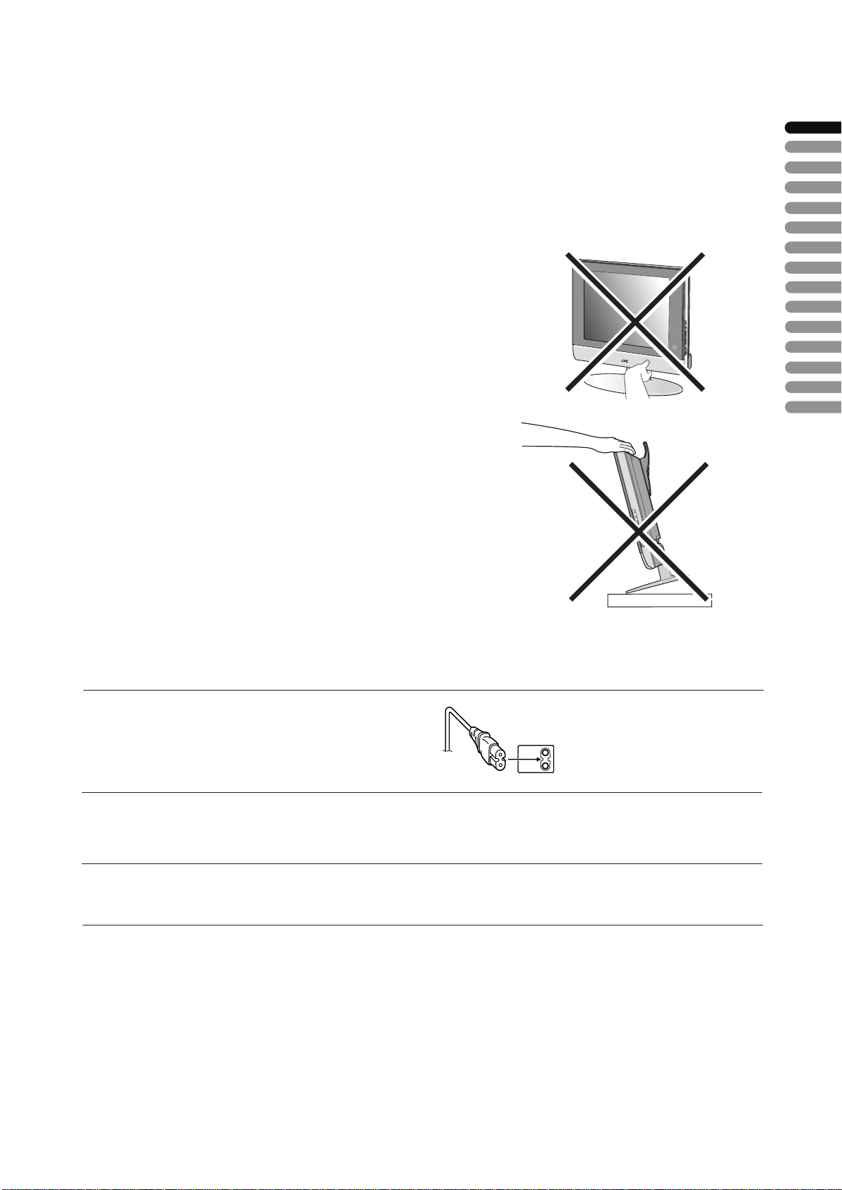
WARNING
• Fingers may be trapped under the TV causing injuries. Hold the TV at the
bottom in the middle, and do not allow it to tilt up or down.
• The TV may fall causing injuries. Hold the bottom of the stand with your
hand and tilt the TV up and down.
• Do not allow children to hang from the TV, place their elbows on the TV
or lean against the TV. Doing so may cause the TV to fall over and leads
to injuires.
CAUTION:
• To avoid electric shock or damage to the unit, first firmly
insert the small end of the power cord into the AC Adpater
unit it is no longer wobbly, and then plug the larger end of
power cord into an AC outlet.
CAUTION:
• Operate only from the power source specified – 240 V,
50/60 Hz) on the AC adapter.
• Avoid damaging the AC plug, AC adapter and power cord.
•
(AC 100 • only
• When you are not using this unit for a long period of time, it is
recommended that you disconnect the power cord from the
main outlet.
ENGLISH
CAUTION ON HEATING OF AC ADAPTER:
In using, the AC adapter get heat on the sunface of case.
•
It is normal, not defective. while it is in operation.
• Don't be covered with any material on case of AC adapter
NOTES:
• The rating plate (serial number plate) and safety caution
are on the back of the main unit.
• The rating information and safty causion of the AC Adapter
are on its upper and lower sides.
1
Page 21
Point defects
LCDs use collections of fine pixels to display images. While there is no problem with more than 99.99% of these pixels, please
understand that a very small number of pixels may not light or may light all the time.
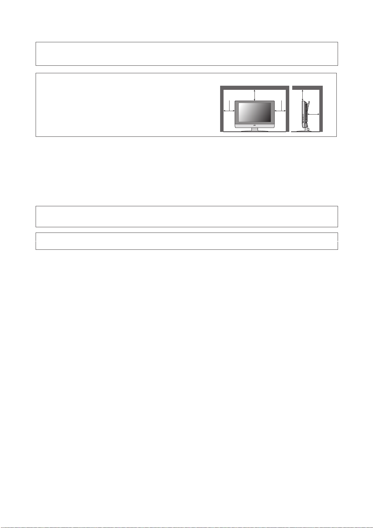
Distance recommendations
Avoid improper installation and never position the unit where good
ventilation is impossible.
When installing this TV, distance recommendations must be maintained
between the set and the wall, as well as inside a tightly enclosed area or
piece of furniture.
150 mm 150 mm
200 mm 200 mm
50 mm
Keep to the minimum distance guidelines shown for safe operation.
Failure to take the following precautions may cause damage to the television or remote control.
DO NOT block the TV’s ventilat ion opening s or holes.
(If the ventilation openings or holes are blocked by a newspaper or cloth, etc., the heat may not be able to get out.)
DO NOT place anything on top of the TV.
(such as cosmetics or medicines, flower vases, potted plants, cups, etc.)
DO NOT allow objects or liquid into the cabinet openings.
(If water or liquid is allowed to enter this equipment, fire or electric shock may be caused.)
DO NOT place any naked flame sources, such as lighted candles, on the TV.
DO NOT subject the TV to direct sunlight.
The surface of the TV screen is easily damaged. Be very careful with it when handling the TV.
Should the TV screen become soiled, wipe it with a soft dry cloth. Never rub it forcefully.
Never use any cleaner or detergent on it.
If there is a fault, unplug the unit and call a service technician. Do not attempt to repair it yourself or remove the rear cover and the
AC adapter.
Cleaning the screen
The screen is coated with a special thin film to reduce reflection. If this film is
and other problems that can not be repaired may occur. Pay attention to the following when handling the screen.
• Do not use glue or adhesive tape on the screen.
• Do not write on the screen.
• Do not allow the screen to come in contact with any hard objects.
• Do not allow condensation to form on the screen.
• Do not use alcohol, thinner, benzene or other solvents on the screen.
• Do not rub the screen hard.
da
maged, uneven colors, discoloration, scratches,
2
Page 22

CONTENTS
Setting up your TV..................................4
Installation..........................................................4
Using the stand........................ ... .......................4
Putting the batteries into the Remote control.....5
Remove the terminal cover................................5
Connecting the aerial and video cassette
recorder (VCR)...................................................6
Connecting the power cord to the AC outlet ......6
Initial settings .........................................7
TV buttons and functions ......................9
Turn the TV on from standby mode...................9
Choose a TV channel ........................................9
Watch images from external devices.................9
Adjust the volume ..............................................9
Using the Menu..................................................9
Remote control buttons and
functions............................................10
Turn the TV on or off from standby mode........10
Choose a TV channel ......................................10
Adjust the volume ............................................11
Watch images from external equipment ..........11
Displaying the source information .....................11
ZOOM function.................................................12
Sleep timer funtion...........................................13
Picture mode....................................................13
Operating a JVC brand VCR or DVD player....1
Sound setting........................................18
Sound Adjustment........................................... 18
HYPER SOUND
.............................................. 18
FEATURES............................................19
BLUE BACK.................................................... 19
CHILD LOCK................................................... 19
EXT-2 OUTPUT............................................... 19
INSTALL................................................20
MANUAL.......................................................... 20
PROGRAM..................................................... 20
To edit the PROGRAM menu.......................... 21
Additional preparation.........................24
Connecting external equipment ...................... 24
ENGLISH
Troubleshooting...................................26
Specifications.......................................28
3
Teletext function...................................14
Basic operation ................................................14
Hold..................................................................14
Sub-page .........................................................14
Reveal..............................................................14
Size..................................................................15
Index ................................................................15
Cancel..............................................................15
Using the TV’s menu............................16
Basic operation ................................................16
Picture setting.......................................17
PICTURE MODE .............................................17
Picture Adjustment...........................................17
COLOUR TEMP...............................................17
RESET..............................................................17
3
Page 23
Setting up your TV
Installation
Cautions for installation
• Install the TV in a corner on a wall or on the floor so as to keep cords out of the way.
• The TV will generate a slight amount of heat during operation. Ensure that sufficient space is available around the TV to allow
satisfactory cooling. See “Distance recommendations” on page 2.
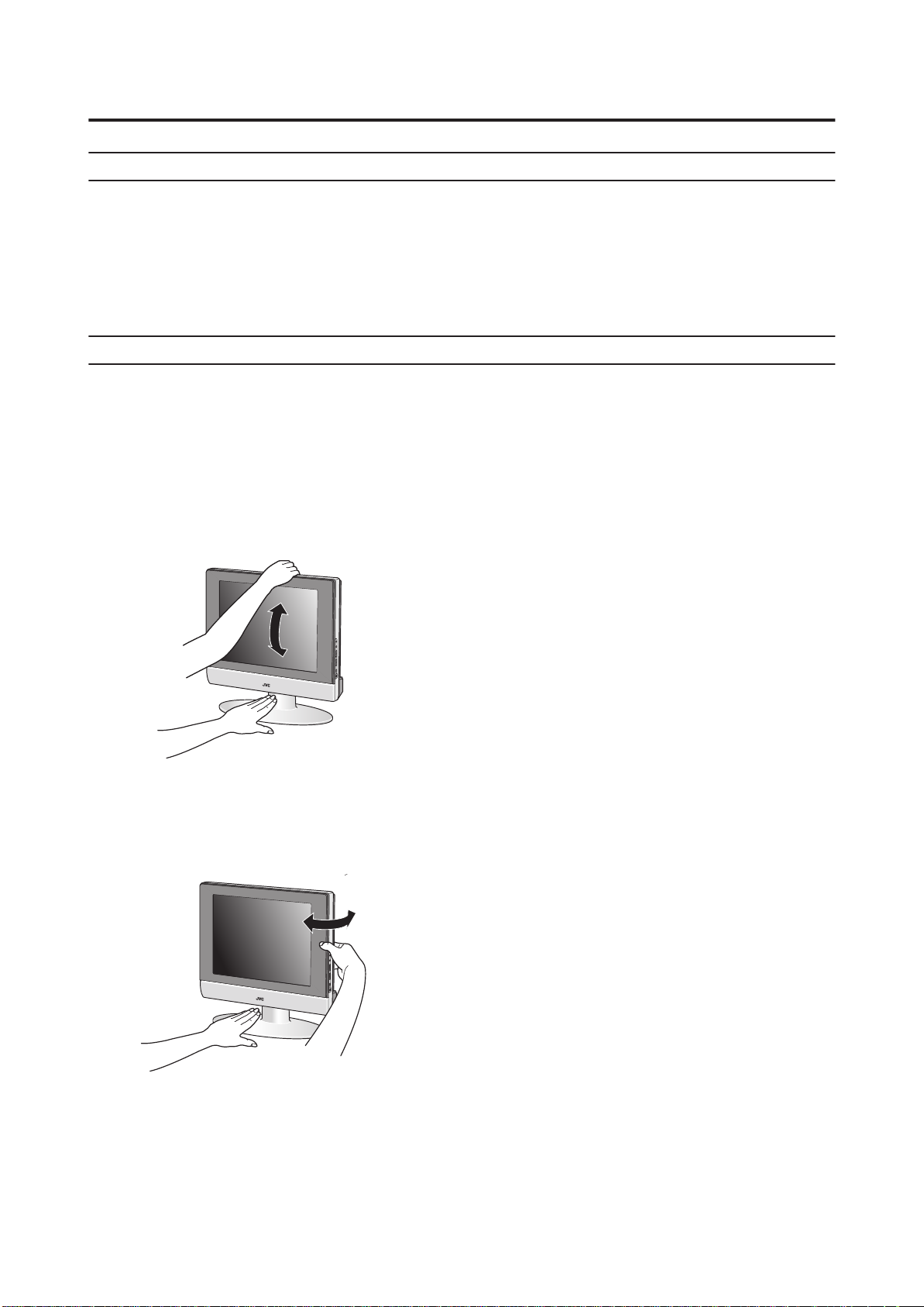
Using the stand
This TV comes with a Table Top Stand already
attached.
This stand can be used to adjust the direction of the TV
screen 5° up, 10° down, and 20° to the left or right.
Tilt the TV up and down:
While holding the bottom of the stand with one hand, use
your other hand to hold the middle of the top of the TV and
slowly tilt the TV up and down.
• As a safety measure, the stand is constructed so that it
requires a certain amount of force to tilt the TV.
Rotate the TV to the left and right:
While holding the bottom of the stand with one hand, use
your other hand to hold the edge of the panel and slowly
adjust the direction of the TV screen.
4
Page 24

Setting up your TV
Putting the batteries into the Remote control
Use two AA/R6 dry cell batteries.
Insert the batteries from the - end, making sure the + and - polarities are correct.
• Follow the warnings printed on the batteries.
• Battery life is about six months to one year, depending on your frequency of use.
• The batteries we supply are only for setting up and testing your TV, please replace them as soon as you need to.
• If the remote control does not work properly, replace the batteries.
Remove the terminal cover
There are connection terminals behind the covers of the rear of the TV. Remove the cover before
connecting a DVD or VCR.
The covers can be removed by removing the hook at the top and then pulling out while lifting slightly. To replace the covers,
first connect the hook at the bottom of the cover to the TV and then insert the hook at the top.
• Leave the covers off if they do not fit properly. Do not force to replace the covers. Doing so may cause damages of the
connection cables and the covers.
• Leave these covers off when mounting the TV on a wall.
ENGLISH
• 100mm mount based on VESA regulation is equipped.
• The handle and the stand can be left by loosing the screws with a screwdriver when mounting the TV on a wall.
• Spread a soft cloth on a flat table and then place the TV on the cloth with the screen facing downwards when you leave the
handle and the stand.
5
Page 25

Setting up your TV
Connecting the aerial and video
cassette recorder (VCR)
• The connecting cables are not provided.
• For further details, refer to the manuals provided with
the devices to be connected.
If you are connecting a VCR, follow
in the diagram below.
If you are not connecting a VCR, follow .
• You can watch a video using the VCR without doing .
For details, see your VCR instruction manual.
• To connect more equipment, please see “Connecting
external equipment” on page 26.
• To connect additional audio equipment, see “Connecting
Speakers/Amplifier” on page 27.
Connecting the power cord to the AC
outlet
If you are connecting a AC adapter,
in the diagram below.
• Connect to the TV and to the AC outlet.
Caution
• Operate only from the power source spec
– 240 V, 50/60 Hz) on the unit.
• Remove the AC plug from the outlet to completely
disconnect the TV from the power supply.
follow
ified (AC 100
75-
ohm
Coaxial
Cable
Aerial
VCR
75-ohm
Coaxial
Cable
To Aerial
Output
21-pi
SCART
Cable
n
6
Page 26

Initial settings
When the TV is first turned on, it enters the initial setting
mode. Follow the
make the initial
instructions on the on-screen display to
settings.
VCR/TV/DVD
Switch
OK
BACK
1 Make sure to set the VCR/TV/DVD switch to the
TV position.
• You cannot turn the TV on when the VCR/TV/DVD
switch is set to the VCR or DVD position.
2 Press the button on the remote control
After a short interval the power lamp changes from red
to green.
• Check that the AC plug on the power cord from the
TV is connected to AC outlet.
Power lamp
3 AUTO PROGRAM menu appears.
AUTO PROGRAM
LANGUAGE ENGLISH
COUNTRY UNITED KINGDOM
A .P .S
4
P
ress
t
:
SELECT
/
he buttons to choose the
:MOVE
LANGUAGE.
5
P
ress
/
t
he buttons to choose the ENGLISH.
LANGUAGE.
The on-screen display will then be in the Language you choosed.
6
P
ress
country where you are.
7
P
ress
A.P.S.
8
Press the OK button to start A.P.S.
/
he and buttons to choose the
t
/
t
he buttons to choose the
Then press buttons.
A.P.S.
START
OK : START
A.P.S.
A.P.S. IS RUNNING
MENU : EXIT
/
/
.
The AUTO PROGRAM menu appears and received TV
channels are automatically stored in the programme
numbers.
• To cancel the AUTO PROGRAM function:
Press the MENU button.
After the TV channels have been registered in
the programme numbers, the PROGRAM
menu appears
• If you want to, you can now edit the programme
numbers using the PROGRAM function.
For details, see “To edit the PROGRAM menu” on
page 21.
ENGLISH
Remote control sensor
7
Page 27

Initial settings
Now, the initial settings are complete, and you can
watch the TV
•
If your TV can detect the TV channel name from the TV
channel broadcast signal, the TV channel name is
assigned to the programme number to which the
TV channel has been set. However, which TV channels
are set to which programme numbers will depend
on the area in which you live.
• If a TV channel you want to view is not set to a
programme number, you can set it using the
MANUAL function. For details, see “To edit the
PROGRAM menu" on page 21.
• The AUTO PROGRAM function does not set the
programme number PR 0 (AV) for your video cassette
recorder. You will need to set this using the MANUAL
function.
• In some areas you may get TV reception from more than
one transmitter, for example different ITV regions. In
this case each TV channel could be set twice. If this
happens, the first set of channels will have the stronger
signal. If you want to delete the second set of channels,
you will have to do it manually (see page 20).
8
Page 28

TV buttons and functions
Turn the TV on from standby mode
1
Press the button or P buttons to turn the TV
/
on from standby mode
• Check that the AC plug on the power cord from the TV
is connected to correctly AC outlet.
Choose a TV channel
Press the P buttons to choose a programme
number or an EXT terminal
/
Watch images from external devices
2
Press the TV/AV OK button to choose a TV/AV
terminal
-1
EXT modes
EXT-2
EXT-3 S
EXT-2 S
EXT-3
TV mode
Last
program
number
EXT
ENGLISH
Adjust the volume
Press the buttons
3
The volume level indicator appears.
1
Power lamp
2 Remote control sensor
3
MENU button
4
TV/AV OK button
5
(Volume) button
/
6
P buttons
Standby botton
7
Headphone jack (mini jack)
8
4
5
Using the Menu
Use the MENU button.
Refer to “Using the TV’s menu” (see page
for details of
16)
using the menu.
6
7
8
9
Page 29

Remote control buttons and functions
1 Muting bu btton
Numbeonr buttons
3 Info rma btuiottn butonton
4 ZOOM button
5
u2tt
6
7 /
buttons
8 (Text) button
9 P buttons
/
10 VCR/DVD/Teletext control buttons
/
11 buttons
12
Standby button
VCR/TV/DVD switch
13
button
14
AV
15
button
16
Picture button
Color buttons
17
MENU button
18
OK
button
19
/
BACK
buttons
button
buttons
20
21
22
Turn the TV on or off from standby
mode
1 Make sure to set the VCR/TV/DVD switch to the
TV position.
• You cannot turn the TV on or off when the VCR/TV/
DVD switch is set to the VCR or DVD position.
2 Press the (standby) button to turn the TV on
or off.
When the TV is turned on, the power lamp changes from
red to green.
• The power can be turned on by pressing
buttons or Number buttons.
P
• Check that the AC plug on the power cord from the
TV is connected to AC outlet.
/
Choose a TV channel
Use the number buttons:
Enter the programme number of the
channel using the number buttons.
Example:
•PR press 66
• PR 12 press 1 and 2
Use the
Press th buttons to choose the
programme number want
• If you do not have a clear picture or no colour appears,
change the colour system manually. Follow the description
"MUNUAL" on page 20 to try to change COLOUR
SYSTEM.
• If the SOUND SYSTEM setting for a TV channel is
incorrect, it may provent the sound from being issued.
Follow the description "MANUAL" on page 20 to try
to change the SOUND SYSTEM setting.
P
e
/
/
P
buttons:
you
.
10
Page 30

Remote control buttons and functions
Adjust the volume
Press the buttons to adjust the volume.
The volume indicator appears and the volume changes as
you press the buttons.
Muting the sound
Press the (muting) button to turn off the
sound.
Pressing the (muting) button again restores the previous
volume level.
Watch images from external equipment
Use the AV button:
Press the
terminal.
TV mode
Last
program
number
To use the Programme number 0:
button to choose an EXT
AV
EXT modes
-1
EXT
EXT-2
EXT-3 S
EXT-2 S
EXT-3
Displaying the source information
You can display the source information and current time on
the screen.
or
i
i
(information) button changes the display as
01 BBC
STEREO
TV
EXT-1
EXT-1
EXT-1
Signal source
12 : 00
No display
Press the (information) button to display the
source information.
Pressing the
follows:
• The source information and current time switched by
i
(information) button.
• The source type :
TV/EXT-1/EXT-2/EXT-2 S/EXT-3/EXT-3 S
• If the programme being watched does not have Teletext
transmission, only a box will be displayed at the same
location.
• When watching videos, an incorrect current time
is sometime displayed.
ENGLISH
When the TV and VCR are connected only by the Aerial
cable, choosing the Programme number 0 allows you to
view images from the VCR. Set the VCR RF channel to
the Programme number 0 manually. For details, see
"MANUAL" on page 20.
11
Page 31

Remote control buttons and functions
ZOOM function
You can change the screen size according to the picture
aspect ratio. Choose the optimum one from the following
ZOOM modes.
AUTO:
The TV
mode or 4:3 mode according to the signal from an external device.
4:3:
Play a 4:3 image in a
16:9:
Play 16:9 size image in the 4:3
automatically chan
ges the ZOOM
4:3 screen faithfully.
screen.
mode to 16:9
12
Page 32

Sleep timer function
The Sleep Timer can turn the TV off for you after you fall
asleep. Program it to work in intervals of 30 minutes, for
a total time of up to 120 minutes.
Press the button.
Picture mode
You can choose one of three PICTURE MODEs to adjust
the picture settings automatically.
Press the PICTURE button.
BRIGHT:
Heightens contrast and sharpness.
STANDARD:
Standardizes picture adjustment.
SOFT:
Softens contrast and sharpness.
Remote control buttons and functions
ENGLISH
Operating a JVC brand VCR or DVD
player
These buttons will operate a JVC brand VCR or DVD
player. Pressing a button that looks the same as the device’s
original remote control button has the same effect as the
original remote control.
1 Set the VCR/TV/DVD switch to the VCR or DVD
position
VCR:
When you are using a VCR, set the switch to the VCR
position. You can turn the VCR on or off with the
(Standby) button.
DVD:
When you are using a DVD player, set the switch to the
DVD position. You can turn the DVD player on or off
with the (Standby) button.
2 Press the VCR/DVD Control Button to control
your VCR or DVD player
• If your device is not made by JVC, these buttons will
not work.
• Even if your device is made by JVC, some of these
buttons may not work, depending on the device you
are using.
• You can use the p buttons to choose a TV channel
the VCR will receive, or choose the chapter the DVD
player plays back.
• Some models of DVD player use the p buttons for
both operating the fast forward/backward functions
and for choosing the chapter.
• Set the VCR/TV/DVD switch to the TV position
when you turn the TV on or off.
/
/
13
Page 33

Teletext function
Basic operation
1 Choose a TV channel with a teletext broadcast
Hold
You can hold a teletext page on the screen for as long as
you want, even while several other teletext pages are being
received.
2 Make sure to set the VCR/TV/DVD switch to the
TV position.
3 Press (Text) button to display the teletext
Pressing (Text) button changes the mode as follows:
TV mode
TEXT--TEXT--TEXT---
Text mode
D1043
4 Choose a teletext page by pressing the P
/
buttons, number buttons or colour buttons
To return to the TV mode:
Press the (Text) button.
• If you have trouble receiving teletext broadcasts,
consult your local dealer or the teletext station.
• The ZOOM function will not work in the TEXT mode.
• You cannot operate menus when viewing a teletext
programme.
• Language display depends on the country which was
set on the COUNTRY menu. If characters on a
Teletext programme do not appear properly, change
the COUNTRY Setting to other country’s.
Press the (Hold) button
Hold indication
To cancel the Hold function:
Press (Hold) button again.
14
Page 34

Teletext function
Sub-page
Some teletext pages include sub-pages that are
automatically displayed.
1 Choose a teletext page that includes sub-pages
Press the button, Sub-page numbers can be viewed
and displayed at the screen.
2 Press the number buttons to choose a sub-page
number
Sxxxx : xxxx is the number 0 ~ 9 that you entered.
For example, sub-page 1 is S0001, you must enter 0,0,
0 and 1 serially to view sub-page S0001.
Reveal
Some teletext pages include hidden text (such as the
answers to a quiz).
You can display the hidden text.
Each time you press the (Reveal) button, text is
hidden or revealed
Size
You can double the height of the teletext display.
Cancel
You can search for a teletext page while watching TV.
1 Press the number button to enter a page
number, or press a colour button
The TV searches for a teletext page.
2 Press the (Cancel) button
The TV programme appears. When the TV finds the
teletext page, its page number appears in the upper left
of the screen.
3 Press the (Cancel) button to return to a
teletext page when the page number is on the
screen
• The TV mode cannot be resumed by pressing the
(Cancel) button. To return to the TV mode press
button.
ENGLISH
Press the (Size) button.
Index
You can return to the index page instantly.
Press the (Index) button
Returns to page 100 or a previously specified page.
15
Page 35

Using the TV’s menu
This TV has a number of functions you can operate using
menus. To use all your TV’s functions, you need to
understand the basic menu operating techniques fully.
BACK
3Press the buttons to choose a function
/
• For details of the functions in the menus, see the
following pages.
4Press the buttons to choose the setting of
/
that function
• If you want to operate a function which appears only
with its name, follow the descriptions of that function
on the following pages.
• The display appearing at the bottom of a menu shows
you a button on the remote control that you can use
when you operate a chosen function.
5Press the
MENU
button to complete the setting
The menu disappears.
• When watching the television with the NTSC system,
the menus are displayed at about half of their normal
vertical size.
• The menu will be disappear if you press the P
/
buttons, the AV button or the number buttons while
the menu is
displayed.
Operation with the buttons on the TV
You can also operate the menus using the buttons on the
front panel of the TV.
Basic operation
1 Press the MENU button to display the MENU (main
menu)
MENU
PICTURE
SOUND
FEATURES
INSTALL
: SELECT OK :MOVE
2 Press the and buttons to choose a
/
menu title, and press the OK button
The menu appears.
To return to the previous menu:
Press the BACK button on the remote control or the
MENU button on the TV.
To exit
a menu instantly:
Press the MENU button on the remote control or
press the MENU button on the TV several times.
/
MENU/OK button
TV/AV button
buttons
/
buttons
/
The menu will disappear after about one minute if no
operation is performed.
16
Page 36

PICTURE SETTING
Refer to “Using the TV’s menu” (see page 16) for details of
displaying the menu.
PICTURE
PICTURE MODE BRIGHT
CONTRAST
BRIGHT-1
SHARP
HUE
COLOUR
BRIGHT-2
COLOUR TEMP. HIGH
RESET
: SELECT
:MOVE
PICTURE MODE
You can choose one of three PICTURE MODEs to adjust
the picture settings automatically.
BRIGHT:
Heightens contrast and sharpness.
STANDARD:
Standardizes picture adjustment.
SOFT:
Softens contrast and sharpness.
Picture Adjustment
You can change the picture settings of each PICTURE
MODE mode as you like.
COLOUR TEMP.
You can select one of three COLOUR TEMP. modes (three
tones of white) to adjust the white balance of the picture.
Since white is the colour which is used as a reference for all
the other colours, changing the COLOUR TEMP. mode
affects the appearance of all the other colours on the screen.
HIGH:
A bluish white. Using this mode when watching bright
pictures allows you to enjoy a more vivid and bright picture.
LOW:
A reddish white. Using this mode when watching films
allows you to enjoy colours that are characteristic of films.
RESET
You can reset the picture settings you have chosen to the
default settings.
ENGLISH
CONTRAST:
You can adjust the picture contrast.
:lower
: higher
BRIGHT-1:
You can adjust the picture brightness.
:darker
: brighter
SHARP:
You can adjust the picture sharpness.
:softer
:sharper
TINT:
You can adjust the picture tint.
:reddish
:greenish
COLOUR:
You can adjust the picture colour.
: lighter
: deeper
BRIGHT-2:
You can adjust the back light.
:darker
:lighter
You can change the HUE setting(picture hue) when the
colour system is NTSC3.58 or NTSC4.43.
17
Page 37

SOUND SETTING
Refer to “Using the TV’s menu” (see page 16) for details of
displaying the menu.
SOUND
BASS
TREBLE
BALANCE
HYPER SOUND OFF
: SELECT
:MOVE
Sound Adjustment
You can adjust the sound to your liking.
BASS:
You can adjust the low tone of the sound.
: weaker
: strong
TREBLE:
You can adjust the high tone of the sound.
: weaker
: strong
BALANCE:
You can adjust the volume balance between the left and
right speaker.
:turn the left speaker’s volume level up.
: turn the right speaker’s volume level up.
HYPER SOUND
You can enjoy Surround sound with a “live” effect by using
the function.
HYPER SOUND
ON:
HYPER SOUND
OFF:
function is turned on.
function HYPER SOUND
is turned off.
18
Page 38

FEATURES
Refer to “Using the TV’s menu” (see page 16) for details of
displaying the menu.
FEATURES
BLUE BACK OFF
CHILD LOCK OFF
EXT-2 OUTPUT TV
: SELECT
BLUE BACK
You can set the TV to automatically change to a blue screen
and mute the sound if the signal is weak or absent, or when
there is no input from an external device.
ON:
This function is turned on.
OFF:
This function is turned off.
:MOVE
CHILD LOCK
When the CHILD LOCK mode is on, the TV buttons will be
locked except Power . TV only can be controled by
remote controller.
EXT-2 OUTPUT
You can choose a signal source to be output from the EXT-2
terminal.
You can do this with the output signals of the devices
connected to EXT-1 or EXT-3 termainal, or with the picture
and sound from a TV channel you are currently viewing.
Press the buttons to choose the
signal source TV/EXT-1/EXT-3.
/
ENGLISH
19
Page 39

INSTALL
Refer to “Using the TV’s menu” (see page 16) for details of
displaying the menu.
In TV mode :
INSTALL
MANUAL
PR LIST
: SELECT OK : MOVE
In EXT mode :
MENU
COLOUR SYSTEM
:
SELECT
SECAM
OK : MOVE
MANUAL
You can store the TV channel for which you needed.
Store them in the TV’s program numbers list
by setting the following.
MANUAL
PROGRAM 01
BAND CC
CHANNEL 02
COLOUR SYSTEM AUTO
SOUND SYSTEM AUTO
SEARCH
FINE TUNING
STORE
: SELECT : MOVE
PROGRAM
AUTO PROGRAM
You can automatically store the TV channels for which you
have the best reception. Store them in the TV’s program
numbers list by doing the following.
Choose PR LIST. Then press the OK button.
1
PR LIST
01 ---02 ---03 ---04 ---05 ---06 ---07 ---08 ---09 ---10 ----
N
INSERT A.P.S.
11 ---12 ---13 ---14 ---15 ---16 ---17 ---18 ---19 ---20 ----
ME DELETE
A
2 Press the blue button, AUTO PROGRAM menu
appears.
AUTO PROGRAM
LANGUAGE ENGLISH
COUNTRY UNITED KINGDOM
A. P. S.
:
SELECT
21 ---22 ---23 ---24 ---25 ---26 ---27 ---28 ---29 ---30 ----
:MOVE
1 Select PROGRAM and press the buttons to
/
choose the program number.
2 Select BAND and press the buttons to
/
choose the band type.
CH(AIR) / CC(CATV)
3 Select CHANNEL and press the buttons to
/
choose the channel number.
4 Select COLOUR SYSTEM and press the
/
buttons to choose the colour system.
AUTO / PAL / SECAM
• If you do not have a clear picture or no colour appears,
change the colour system.
5 Select SOUND SYSTEM and press the
/
buttons to choose the sound system.
AUTO / B/G / D/K / L / I
• If the SOUND SYSTEM setting for a TV channel is
incorrect, it may provent the sound from being issued.
6 Select SEARCH and press the buttons to
/
choose the serviceable TV channel.
7 If the channel reception is poor, select
FINE TUNING and press the buttons to
/
fine tune the program.
8 Select Store and press the buttons to
/
store the manual setting.
3
P
ress
/
he buttons to choose the
t
LANGUAGE.
4
P
ress
/
t
he buttons to choose the
ENGLISH.
The on-screen display will then be in English.
5
P
ress
country where you are.
/
he and buttons to choose the
t
/
6
P
ress
Th
en press the buttons.
/
he buttons to choose the A.P.S.
t
A.P.S.
START
OK : START
/
7
P
he OK button to start the A.P.S.
ress
t
A.P.S.
A.P.S. IS RUNNING
MENU : EXIT
The AUTO PROGRAM menu appears and received TV
channels are automatically stored in the programme
numbers.
• To cancel the AUTO PROGRAM function:
Press the MENU button.
20
Page 40

INSTALL
0
0
BBC1
After the TV channels have been registered in
the programme numbers, the PR LIST menu
appears
• If you want to, you can now edit the program
numbers using the PROGRAM function.
For details, see “To edit theP ROGRAM menu” as follows.
To edit the PR LIST menu
You can edit the programme numbers.
Caution
• Using the NAME, DELETE or INSERT functions
rewrites the current programme numbers list.
Therefore, the programme nu of some of
the TV channels will change.
1 Choose PR LIST, then press the OK button
PR LIST
01 ---02 ---03 ---04 ---05 ---06 ---07 ---08 ---09 ---10 ----
N
AME DELETE
INSERT A.P.S.
2 Follow the operation description of a function
you want to use and operate the function
NAME:
This function registers a channel name (ID) to a TV
channel.
INSERT:
This function changes a programme number of a
TV channel.
DELETE:
This function deletes a TV channel you do not want to
list.
A.P.S:
This function received TV channels automatically
amnd stored in program numbers. For details,
see "AUTO PROGRAM" on page 20.
11 ---12 ---13 ---14 ---15 ---16 ---17 ---18 ---19 ---20 ----
mber
21 ---22 ---23 ---24 ---25 ---26 ---27 ---28 ---29 ---30 ----
NAME
and
/
11 ---12 ---13 ---14 ---15 ---16 ---17 ---18 ---19 ---20 ----
11 ---12 ---13 ---14 ---15 ---16 ---17 ---18 ---19 ---20 ----
11 ---12 ---13 ---14 ---15 ---16 ---17 ---18 ---19 ---20 ----
/
/
and
/
21 ---22 ---23 ---24 ---25 ---26 ---27 ---28 ---29 ----
30 ----
CANCEL
21 ---22 ---23 ---24 ---25 ---26 ---27 ---28 ---29 ----
30 ----
CANCEL
21 ---22 ---23 ---24 ---25 ---26 ---27 ---28 ---29 ---30 ----
to edit the
1 Press t
he and buttons to choose a TV
/
channel
Every time you press the buttons, the
programme number changes and the picture of the
TV channel stored in the programme number appears
on the screen.
2 Press the red button to start the NAME function
PR LIST
01 ---02 ----
03 ---04 ---05 ---06 ---07 ---08 ---09 ---10 ----
STORE
3 Press the buttons
/
channel name you want to give the TV channel
PR LIST
01 ---02
BBC1
03 ---04 ---05 ---06 ---07 ---08 ---09 ---10 ----
STORE
4 Press the red button to store the setting
PR LIST
01 ---02
BBC1
03 ---04 ---05 ---06 ---07 ---08 ---09 ---10 ----
NAME DELETE
INSERT A.P.S.
ENGLISH
To return to the INSTALL menu:
Press the BACK button.
To exit
a menu instantly:
Press the MENU button.
21
Page 41

INSTALL
0
2
BBC1
0
2
BBC1
0
BBC1
0
1
----
0
1
BBC1
INSERT
1 Press t
he and buttons to choose a
/
program number for which you want
Every time you press the buttons, the
programme number changes and the picture of the
TV channel stored in the programme number appears
on the screen.
PR LIST
01 ---02
BBC1
03
BBC2
04 ---05 ---06 ---07 ---08 ---09 ---10 ----
NAME
INSERT A.P.S.
2 Press the green button to start the INSERT
function
/
11 ---12 ---13 ---14 ---15 ---16 ---17 ---18 ---19 ---20 ----
and
/
21 ---22 ---23 ---24 ---25 ---26 ---27 ---28 ---29 ---30 ----
DELETE
/
4 Press the green button to insert the channel into
the new program number
PR LIST
01
BBC1
02 ---03
BBC2
04 ----
05 ---06 ---07 ---08 ---09 ----
10 ----
11 ----
12 ---13 ---14 ---15 ---16 ---17 ---18 ---19 ---20 ----
21 ---22 ---23 ---24 ---25 ---26 ---27 ---28 ---29 ---30 ----
NAME DELETE
INSERT A.P.S.
To return to the INSTALL menu:
Press the BACK button.
To exit
a menu instantly:
Press the MENU button.
PR LIST
3 Press t
he and buttons to choose a new
program number
PR LIST
01 ---02
BBC1
03
BBC2
04 ---05 ---06 ---07 ---08 ---09 ---10 ----
11 ---12 ---13 ---14 ---15 ---16 ---17 ---18 ---19 ---20 ----
21 ---22 ---23 ---24 ---25 ---26 ---27 ---28 ---29 ---30 ----
INSERT CANCEL
/
01 ----
02
BBC1
03
BBC2
04 ---05 ---06 ---07 ---08 ---09 ---10 ----
/
11 ---12 ---13 ---14 ---15 ---16 ---17 ---18 ---19 ---20 ----
21 ---22 ---23 ---24 ---25 ---26 ---27 ---28 ---29 ---30 ----
INSERT CANCEL
22
Page 42

INSTALL
0
3
BBC2
0
3
BBC2
0
3
DELETE
1 Press t
he and buttons to choose a
/
program number for which you want
Every time you press the buttons, the
programme number changes and the picture of the
TV channel stored in the programme number appears
on the screen.
PR LIST
01 ---02
BBC1
03
BBC2
04 ---05 ---06 ---07 ---08 ---09 ---10 ----
NAME
INSERT A.P.S.
2 Press the yellow button to start DELETE
function
PR LIST
01 ---02
BBC1
03
BBC2
04 ---05 ---06 ---07 ---08 ---09 ---10 ----
/
and
/
11 ---12 ---13 ---14 ---15 ---16 ---17 ---18 ---19 ---20 ----
11 ---12 ---13 ---14 ---15 ---16 ---17 ---18 ---19 ---20 ----
DELETE
/
21 ---22 ---23 ---24 ---25 ---26 ---27 ---28 ---29 ---30 ----
DELETE
21 ---22 ---23 ---24 ---25 ---26 ---27 ---28 ---29 ----
30 ----
CANCEL
COLOUR SYSTEM in EXT mode
he buttons to choose the colour system
Press t
When you are in EXT mode, you can only change the
colour system in the INSTALL menu.
/
ENGLISH
3 Press the yellow button to delete the selected
TV channel
The TV channel is deleted from the programme numbers
list.
PR LIST
01 ---02
BBC1
----
03
04 ---05 ---06 ---07 ---08 ---09 ---10 ----
NAME
11 ---12 ---13 ---14 ---15 ---16 ---17 ---18 ---19 ---20 ----
DELETE
21 ---22 ---23 ---24 ---25 ---26 ---27 ---28 ---29 ---30 ----
INSERT A.P.S.
To return to the INSTALL menu:
Press the BACK button.
To exit
a menu instantly:
Press the MENU button.
23
Page 43

Additional preparation
Connecting external equipment
Connect the equipment to the TV, making the correct rear
panel and front panel connections.
Before connecting anything:
• Read the manuals that came with the equipment.
Depending on the equipment, the connection method
may be different from the diagram. Also, the equipment
settings may need to change depending on the
connection method.
• Turn off all the equipment including the TV.
• The “Specifications” on page 30 give the details of the
EXT terminals. If you are connecting equipment not
listed in the following connection diagram, see the table
to choose the best EXT terminal.
• Connecting cables are not supplied.
1 VCR (composite signal)
2 VCR (composite signal/S-VIDEO signal)
3
Decoder
4
DVD player (composite signal/S-VIDEO signal)
5
DVD player (composite signal/RGB signal)
6
TV game (composite signal/RGB signal)
7
TV game (composite signal/S-VIDEO signal)
8
Headphones
9
Camcorder (composite signal/S-VIDEO signal)
10
SCART cable
11
Video cable
12
S-VIDEO cable
13
Audio cable
234 5 678
1 356
9 7
8
10
12
11
13
24
Page 44

Additional preparation
Equipment which can output the S-VIDEO
signal (Y/C signal) such as an S-VHS VCR
Connect the equipment to an EXT terminal (but not the
EXT-1 terminal).
You can choose between an S-VIDEO signal (Y/C signal).
Connecting headphones
Connect the headphones with a stereo mini-jack (3.5 mm
diameter) to the headphone socket at the TV.
Video or sound signal output from the EXT-2
terminal
You can change over the output of the video/sound signal
from the EXT-2 terminal. This is useful when you want to
dub the video/sound from another device onto the VCR
connected to the EXT-2 terminal.
TV output from the EXT-1 terminal
The video/sound signal of a TV channel you are viewing is
always output from the EXT-1 terminal.
• Changing over a programme number also changes
over the TV output from the EXT-1 terminal.
• The video/sound signal from an EXT terminal cannot be
output.
• Teletext programmes cannot be output.
ENGLISH
25
Page 45

Troubleshooting
If a problem arises while you are using the TV, please read this troubleshooting guide carefully before you ask to have the TV
repaired. You may be able to fix it easily by yourself. For example, if the mains plug is disconnected from the mains outlet, or the
TV aerial has problems, you may think there is a problem with the TV itself.
Important:
• This troubleshooting guide only covers problems whose causes are not easy to decide. If you have a question when you are
operating a function, read the page(s) for that function carefully, not this troubleshooting guide.
• If you follow the advice in this troubleshooting guide without any success, unplug the mains plug and ask for your TV to be
repaired. Do not attempt to repair the TV by yourself or to remove the rear cover of the TV.
If you cannot turn on the TV
• Are the AC plug on the power cord from the TV is
connected to AC outlet?
• Make sure to set the VCR/TV/DVD switch to the TV
position. You cannot turn the TV on when the VCR/TV/
DVD switch is set to the VCR or DVD position.
If you cannot turn off the TV
• Make sure to set the VCR/TV/DVD switch to the TV
position. You cannot turn the TV off when the VCR/TV/
DVD switch is set to the VCR or DVD position.
No picture or no sound
• Have you chosen a TV channel with very poor
reception? If so, the BLUE BACK function will be
activated: the entire screen becomes blue, and the sound
is muted. If you still want to view the TV channel,
follow the description “BLUE BACK” on page 19 to
change the BLUE BACK function setting to OFF.
• If the SOUND SYSTEM setting for a tTV channel is
incorrect, it may prevent the sound from being issued.
Follow the description “INSTALL” on page 20 to use the
MANUAL function to try to change the SOUND SYSTEM
setting.
Poor picture
• If noise (snow) totally blocks out the picture, there may
be a problem with the aerial or aerial cable. Check the
following to try to solve the problem:
–Have the TV and aerial been connected properly?
–Has the aerial cable been damaged?
–Is the aerial pointing in the right direction?
–Is the aerial itself faulty?
• If the TV or aerial suffers interference from other
equipment, stripes or noise may appear in the picture.
Move any equipment such as an amplifier, personal
computer, or a hair drier, that can cause interference
away from your TV. Or try moving the TV. If the aerial
suffers interference from a radio tower or high-voltage
wire, please contact your local dealer.
• If the TV suffers interference from signals reflecting
from mountains or buildings, double-pictures (ghosting)
will occur. Try to change the aerial’s direction or replace
it with one with better directionality.
• Have the COLOUR and BRIGHT settings been adjusted
properly? Follow the description “Picture Adjustment”
on page 17 to try to adjust them properly.
• Videotaping teletext is not recommended because it may
not record correctly.
• When viewing images from commercially available
video software products, or videos from videotapes
which have been recorded improperly, the top of the
image may be distorted. This is due to the condition of
the video signal. There is nothing wrong with the TV.
Poor sound
• Have you adjusted BASS or TREBLE properly? If not,
follow the description “Sound Adjustment” on page 18.
If the TV does not respond to the remote
control
• Have the batteries of the remote control worn out?
Follow the description “Putting the batteries into the
Remote control” on page 5 and replace them with new
batteries.
• Have you attempted to use the remote control from the
sides or rear of the TV or from more than seven metres
away from the TV? Use the remote control in the front of
your TV or from less than seven metres away.
• When you are viewing a teletext programme, you cannot
operate the menus. Press the button to return to the
ordinary TV programme, and then try operating the
menus.
• If the TV suddenly stops responding, disconnect the
power cord of the TV from the AC outlet.
Connect them to the AC outlet again to turn on the TV.
If the TV returns to a normal state, it is not a failure.
26
Page 46

Other concerns
• When the SLEEP TIMER function operates, the TV is
automatically turned off. If the TV suddenly turns off,
try to press the (standby) button to turn on the TV
once again. If the TV goes back to normal, there is no
problem.
• When the TV is receiving
device affecting the
automatically c
previous ZOOM mode, press the
• It takes a short period of time from the time an operation
such as changing channels is performed until an image is
displayed. This is not a malfunction. This is the time
required for the image to stabilize before it can be
displayed.
• The TV may make a crackling sound due to a sudden
change in temperature. The picture or sound may be
normal. If you hear crackling sounds frequently while
you are viewing the TV, there may be other causes. As a
precaution, ask your service technician to inspect it.
• The top of the TV and the screen may become hot during
use but this has no affect on the performance of the TV.
Ensure that the ventilation holes are not blocked.
• When the picture is unstable, the screen may become
white for a moment. This occurs when the signal which
drives the liquid crystal is missing. This is not a
malfunction.
• When a still image has been displayed for a long period,
a faint residual image may remain on the screen for a
short time after the power has been turned off or when
another image is displayed. This is not a malfunction and
the image will eventually disappear.
hanges. When you
a signal from an external
screen
size, the ZOOM mode
want to resume the
ZOOM
button again.
Troubleshooting
ENGLISH
27
Page 47

Specifications
Item
Model
Broadcasting systems CCIR B/G, I, D/K, L
Colour systems PAL, SECAM
Channels and frequencies • E2-E12, E21-E69, S1-S41, X, Y, Z, Z+1, Z+2, ITALY A-H, ITALY H+1, ITALY H+2, F2-F10, F21-F69, R1-R12,
Sound-multiplex systems A2 (B/G, D/K), NICAM (B/G, I, D/K, L) system
Teletext systems FLOF (Fastext), TOP, WST (World Standard System)
Power requirements
Power consumption 60 W, Standby:<1 W
Screen size Viewable area 51.05 cm (measured diagonally)
Display resolution 640 x 480
Audio output Rated Power output: 3 W + 3 W
Speakers
EXT-1 terminal Euroconnector (21-pin, SCART)
EXT-2 terminal Euroconnector (21-pin, SCART)
EXT-3 terminal
Headphone jack
Dimensions (W H D)
• The EXT terminals also support the NTSC 3.58/4.43 MHz system.
R21-R69, IR A-J
• French cable TV channel of broadcast frequencies 116 - 172 MHz and 220 - 469 MHz
TV : 12V DC, AC adapter : 100 - 240 V AC, 50/60 Hz
50 x 38 x 20 mm BOX x 2
• Video input, Audio L/R inputs and RGB inputs are available.
• TV broadcast outputs (Video and Audio L/R) are available.
• Video input, S-VIDEO (Y/C) input, Audio L/R inputs and RGB inputs are available.
• Video and Audio L/R outputs are available.
RCA connectors x 3, S-VIDEO connector x 1
•
Video input, S-VIDEO(Y/C) and Audio L/R inputs are available.
Stereo mini-jack (3.5 mm in diameter)
540.6 mm x 415.6 mm x 91.2 mm (TV only)
430.6 mm x 476.5 mm x 224.6 mm
LT-20C70BU
Weight
Accessorie
s
9.6 kg (TV only)
13.8 kg
Remote control unit x 1 (RM-C1861)
AA/
dry cell battery x 2
R6
AC adapter x 1
Power cord x 1
Design and specifications subject to change without notice.
Pictures displayed on the screen using this TV’s ZOOM functions should not be shown for any commercial or demonstration purpose
in public places (cafes, hotels, etc.) without the consent of the owners of copyright of the original picture sources, as this constitutes an
infringement of copyright.
28
Page 48

SCHEMATIC DIAGRAMS
LCD FLAT TELEVISION
LT-20C70BU
CD-ROM No. SML200609
BACK
COPYRIGHT © 2006 Victor Company of Japan, Limited
No.YA436
2006/9
Page 49

LT-20C70BU
STANDARD CIRCUIT DIAGRAM
CONTENTS
USING P.W. BOARD...................................................................................... 2-1
SEMICONDUCTOR SHAPES ......................................................................2-1
BLOCK DIAGRAM ........................................................................................2-2
CIRCUIT DIAGRAMS
MAIN PWB CIRCUIT DIAGRAM ................................................................................................................ 2-3
IR PWB CIRCUIT DIAGRAM .................................................................................................................... 2-25
KEY PWB CIRCUIT DIAGRAM ................................................................................................................. 2-26
PATTERN DIAGRAMS
MAIN PWB PATTERN .............................................................................................................................. 2-27
IR PWB PATTERN .................................................................................................................................... 2-29
KEY PWB PATTERN ................................................................................................................................ 2-29
USING P.W. BOARD
P.W.B ASS’Y name
MAIN P.W. BOARD
KEY P.W. BOARD
IR P.W. BOARD
DA-5098801104 (PWB-0997-A)
DA-5098801105 (PWB-0997-B)
DA-5098801106 (PWB-0997-C)
LT-20C70BU
SEMICONDUCTOR SHAPES
TRANSISTOR
BOTTOM VIEW FRONT VIEW TOP VIEW
CHIP TR
E
C
B
ECB
IC
BOTTOM VIEW FRONT VIEW TOP VIEW
OUT
E
IN
IN OUTE
CHIP IC
B
(G)E(S)C(D)
TOP VIEW
1 N
1
ECB
ECB
1
1 N
C
BE
N
N
1
N
(No.YA436)2-1
Page 50

BLOCK DIAGRAM
SPEAKER(L)
L
P606
L/R
KEY PWB
P607 P609
P012
I027
SPEAKER(R)
R
AMP
HEADPHONE
P608
P006 P001
KPD KPD
TXOUT0+/-
TXOUT1+/-
TXOUT2+/-
I037
YC SEP./
LVDS FORMAT
VIDEO SELECT/
RGB PROCESS/
LCD
UNIT
PANEL
I031
LVDS
INTERFACE
TXOUT3+/-
TXCLK+/-
CONVERSION
I032
DDRAM
ADDRESS
DATA
KPD
INVERTER PWB
MEMORY
I013,I015
I016
MAIN CPU
I033
AUDIO
AIR/AIL
AIR2/AIL2
MAIN PWB
2IF/MPX 2IF/MPX
TV MTS_L/MTS_R
U601
TUNER
CONTROL
AVSV_L_IN/AVSV_R_IN
TV
CIN/Y
P011
RGB_C
SCART1
CIN/Y2
RGB_C2
P010
SCART2
S_LUM/S_CHR
P602
S-VIDEO
COMP
P603
V
L/R
P604,P605
REMOTE
P009
P601
IR601
RECIEVER
REMOCON
LED1/LED2
D601
IR PWB
2-2(No.YA436)
Page 51

CIRCUIT DIAGRAMS
MAIN PWB CIRCUIT DIAGRAM (1/11) SHEET 1
DC12V
!
!
(OPEN)
SHEET7
LCD PANEL UNIT
SHEET7,8
SHEET7
MAIN PWB ASS'Y(1/11)
PWB-0997-01.001_0417_1/12_0.0
2-4(No.YA436)(No.YA436)2-3
Page 52

MAIN PWB CIRCUIT DIAGRAM (2/11) SHEET 2
(No.YA436)2-5 2-6(No.YA436)
MAIN PWB ASS'Y(2/11)
PWB-0997-01.002_0417_2/12_0.0
Page 53

MAIN PWB CIRCUIT DIAGRAM (3/11) SHEET 3
(OPEN)
OPEN
SHEET
7,10
(OPEN)
(OPEN)
(OPEN)
(OPEN)
(OPEN)
(OPEN)
(OPEN)
(OPEN)
(OPEN)
(OPEN)
(OPEN)
(OPEN)
(OPEN)
SHEET10
SHEET10
(OPEN)
SHEET7
SHEET7
SHEET6
OPEN
SHEET7
(OPEN)
(OPEN)
IR PWB ASS'Y
P601
(SHEET12)
(OPEN)
KEY PWB ASS'Y
P609
(SHEET12)
SHEET7
MAIN PWB ASS'Y(3/11)
PWB-0997-01.003_0417_3/12_0.0
2-8(No.YA436)(No.YA436)2-7
Page 54

MAIN PWB CIRCUIT DIAGRAM (4/11) SHEET 4
MAIN PWB ASS'Y(4/11)
SHEET7
SHEET8
(OPEN)
(OPEN)
!
LCD
PANEL UNIT
SHEET4
SHEET4
SHEET4
PWB-0997-01.004_0417_4/12_0.0
(No.YA436)2-9 2-10(No.YA436)
Page 55

MAIN PWB CIRCUIT DIAGRAM (5/11) SHEET 5
SHEET8
SHEET10
SHEET10
SHEET7
SHEET7
SHEET6
SHEET8
SHEET10
SHEET6
SHEET6
SHEET10
SHEET7
SHEET7
SHEET6
SHEET6
SHEET10
SHEET6
SHEET6
SHEET10
SHEET7
MAIN PWB ASS'Y(5/11)
PWB-0997-01.005_0417_5/12_0.0
2-12(No.YA436)(No.YA436)2-11
Page 56

MAIN PWB CIRCUIT DIAGRAM (6/11) SHEET 6
SHEET5
SHEET5
SHEET7
SHEET5
SHEET3
SHEET5
SHEET7
SHEET8
SHEET7
SHEET5
SHEET8
SHEET5
SHEET5
SHEET7
(No.YA436)2-13 2-14(No.YA436)
SHEET8
SHEET7
MAIN PWB ASS'Y(6/11)
PWB-0997-01.006_0417_6/12_0.0
Page 57

MAIN PWB CIRCUIT DIAGRAM (7/11) SHEET 7
SHEET7
SHEET7,8
SHEET7
SHEET7,8
SHEET6
SHEET7,8
(OPEN)
SHEET5
OPEN
SHEET4
SHEET5
SHEET7,8
(OPEN)
(OPEN)
(OPEN)
MAIN CPU
SHEET7,8
(OPEN)
SHEET7
SHEET7,8
SHEET7
SHEET7
SHEET8
SHEET7,8
SHEET7
SHEET7,8
(OPEN)
SHEET7,8
SHEET8
SHEET8
SHEET7
SHEET1,8
SHEET3
(OPEN)
(OPEN)
(OPEN)
(OPEN)
(OPEN)
(OPEN)
(OPEN)
(OPEN)
(OPEN)
(OPEN)
SHEET8
(OPEN)
(OPEN)
(OPEN)
(OPEN)
(OPEN)
SHEET1
(OPEN)
SHEET6
(OPEN)
(OPEN)
OPEN
(OPEN)
(OPEN)
SHEET7
SHEET3
SHEET8
SHEET3
(OPEN)
SHEET3
SHEET3,7,10
SHEET11
(OPEN)
SHEET7
(OPEN)
SHEET3,7,10
OPEN
MAIN PWB ASS'Y(7/11)
OPEN
PWB-0997-01.007_0417_7/12_0.0
2-16(No.YA436)(No.YA436)2-15
Page 58

MAIN PWB CIRCUIT DIAGRAM (8/11) SHEET 8
SHEET9
SHEET9
SHEET9
SHEET7
SHEET8
SHEET8
SHEET7
SHEET9
SHEET9
SHEET9
(OPEN)
(OPEN)
(OPEN)
SHEET8
SHEET9
SHEET8
SHEET7
SHEET8
SHEET7
(OPEN)
(OPEN)
SHEET8
(OPEN)
(OPEN)
(OPEN)
SHEET7
(OPEN)
(OPEN)
(OPEN)
SHEET7
SHEET7
SHEET8
SHEET1,7
SHEET8
SHEET8
SHEET8
SHEET8
SHEET8
(OPEN)
SHEET4
SHEET5
SHEET6
SHEET8
SHEET8
SHEET8
SHEET8
SHEET8
SHEET8
SHEET8
SHEET8
SHEET8
SHEET8
SHEET8
SHEET8
SHEET8
SHEET8
SHEET8
SHEET8
SHEET8
SHEET8
SHEET8
SHEET8
SHEET8
(No.YA436)2-17 2-18(No.YA436)
SHEET8
MAIN PWB ASS'Y(8/11)
PWB-0997-01.008_0417_8/12_0.0
Page 59

MAIN PWB CIRCUIT DIAGRAM (9/11) SHEET 9
SHEET8
SHEET9
SHEET8
SHEET8
SHEET8
SHEET8
SHEET8
SHEET8
SHEET9
SHEET9
DDR RAM
SHEET8
SHEET8
MAIN PWB ASS'Y(9/11)
PWB-0997-01.009_0417_9/12_0.0
2-20(No.YA436)(No.YA436)2-19
Page 60

MAIN PWB CIRCUIT DIAGRAM (10/11) SHEET 10
SHEET3
SHEET5
SHEET3
SHEET3,7
AUDIO
CONTROL
(OPEN)
(OPEN)
(OPEN)
(OPEN)
SHEET5
(OPEN)
SHEET11
SHEET11
(No.YA436)2-21 2-22(No.YA436)
MAIN PWB ASS'Y(10/11)
PWB-0997-01.010_0417_10/12_0.0
Page 61

MAIN PWB CIRCUIT DIAGRAM (11/11) SHEET 11
SHEET10
(OPEN)
SHEET10
SHEET7
KEY PWB ASS'Y
P607
(SHEET12)
MAIN PWB ASS'Y(11/11)
PWB-0997-01.011_0417_11/12_0.0
2-24(No.YA436)(No.YA436)2-23
Page 62

IR PWB AND KEY PWB CIRCUIT DIAGRAM SHEET 12
MAIN PWB
ASS'Y (3/11)
P009
(SHEET3)
IR PWB ASS'Y
MAIN PWB
ASS'Y (11/11)
P012
(SHEET11)
REMOCON
RECEIVER
MAIN PWB
ASS'Y (3/11)
P006
(SHEET3)
KEY PWB ASS'Y
(No.YA436)2-25 2-26(No.YA436)
PWB-0997-01.012_0417_12/12_0.0
Page 63

PATTERN DIAGRAMS
MAIN PWB PATTERN
TOP
()
2-28(No.YA436)(No.YA436)2-27
Page 64

T
TOP
TOP
IR PWB AND KEY PWB PATTERN
FRON
(No.YA436)2-29 2-30(No.YA436)
Page 65

Victor Company of Japan, Limited
Flat Panel Display Category 12, 3-chome, Moriya-cho, Kanagawa-ku, Yokohama-city, Kanagawa-prefecture, 221-8528, Japan
(No.YA436)
Printed in Japan
VPT
Page 66

PARTS LIST
CAUTION
J The parts identified by the symbol are important for the safety . Whenever replacing these parts, be sure to use specified ones to secure the
safety.
J The parts not indicated in this Parts List and those which are filled with lines --- in the Parts No. columns will not be supplied.
J P.W. BOARD Ass'y will not be supplied, but those which are filled with the Parts No. in the Parts No. columns will be supplied.
ABBREVIATIONS OF RESISTORS, CAPACITORS AND TOLERANCES
RESISTORS CAPACITORS
CR Carbon Resistor C CAP. Ceramic Capacitor
FR Fusible Resistor E CAP. Electrolytic Capacitor
PR Plate Resistor M CAP. Mylar Capacitor
VR Variable Resistor CH CAP. Chip Capacitor
HV R High Voltage Resistor HV CAP. High Voltage Capacitor
MF R Metal Film Resistor MF CAP. Metalized Film Capacitor
MG R Metal Glazed Resistor MM CAP. Metalized Mylar Capacitor
MP R Metal Plate Resistor MP CAP. Metalized Polystyrol Capacitor
OM R Metal Oxide Film Resistor PP CAP. Polypropylene Capacitor
CMF R Coating Metal Film Resistor PS CAP. Polystyrol Capacitor
UNF R Non-Flammable Resistor TF CAP. Thin Film Capacitor
CH V R Chip Variable Resistor MPP CAP. Metalized Polypropylene Capacitor
CH MG R Chip Metal Glazed Resistor TAN. CAP. Tantalum Capacitor
COMP. R Composition Resistor CH C CAP. Chip Ceramic Capacitor
LPTC R Linear Positive Temperature Coefficient Resistor BP E CAP. Bi-Polar Electrolytic Capacitor
CH AL E CAP. Chip Aluminum Electrolytic Capacitor
CH AL BP CAP. Chip Aluminum Bi-Polar Capacitor
CH TAN. E CAP. Chip Tantalum Electrolytic Capacitor
CH AL BP E CAP. Chip Tantalum Bi-Polar Electrolytic Capacitor
RESISTORS
FGJ KMNRHZ P
±1% ±2% ±5% ±10% ±20% ±30%
+30%
-10%
+50%
-10%
+80%
-20%
+100%
-0%
(No.YA436)3-1
Page 67

CONTENTS
USING P.W. BOARD & REMOTE CONTROL UNIT ................................................................................................... 3-3
EXPLODED VIEW PARTS LIST ................................................................................................................................. 3-3
EXPLODED VIEW ....................................................................................................................................................... 3-4
PRINTED WIRING BOARD PARTS LIST ................................................................................................................... 3-5
MAIN P.W. BOARD ASS'Y (DA-5098801104) (PWB-0997-A) .......................................................................... 3-5
KEY P.W. BOARD ASS'Y (DA-5098801105) (PWB-0997-B) ............................................................................ 3-9
IR P.W. BOARD ASS'Y (DA-5098801106) (PWB-0997-C) ...............................................................................3-9
PACKING ................................................................................................................................................................... 3-10
PACKING PARTS LIST ............................................................................................................................................. 3-10
3-2(No.YA436)
Page 68

USING P.W. BOARD & REMOTE CONTROL UNIT
P.W.B ASS'Y LT-20C70BU
MAIN P.W.B DA-5098801104 (PWB-0997-A)
KEY P.W.B DA-5098801105 (PWB-0997-B)
IR P.W.B DA-5098801106 (PWB-0997-C)
INVERTER P.W.B DA-E053911125
REMOTE CONTROL UNIT DA-E052731132
EXPLODED VIEW PARTS LIST
Ref.No. Part No. Part Name Description Local
1 DA-E641415112 NECK COVER
2 DA-E641414901 HINGE COVER
3 DA-G190540084 SCREW M4X16(x4)
4 DA-E642025401 RUBBER FOOT (x6)
5 DA-G190564408 SCREW M4X8(x4)
6 DA-G034250655 SCREW M4X6(x7)
7 DA-E640408600 BASE PLATE
8 DA-E641415002 BASE COVER
9 DA-E640408500 HINGE
10 DA-G134251682 SCREW M4X12(x4)
11 DA-E642204501 REAR COVER
12 DA-E648731701 VESA BRACKET
13 DA-G136160652 SCREW M3X6(x17)
14 DA-E642328000 AV COVER
15 DA-E646260300 MAIN PWB SIDE SHIELD
16 DA-E646260400 MAIN PWB SHIELD
17 DA-E642327900 TUNER COVER
18 DA-E642318810 D-SUB COVER
19 DA-G134251482 SCREW M4X10(x5)
20 DA-G001261612 SCREW M4X12(x4)
21 DA-E648749701 LCD BRACKET
22 DA-E051253037 LCD PANEL UNIT
23 DA-E640228400 SCREW M3X14(x4)
24 DA-E055109003 SPEAKER SP01
25 DA-E055109004 SPEAKER SP02
26 DA-E642024717 RUBBER PAD (x2)
27 DA-G134161182 SCREW M3X8(x6)
28 DA-E642319503 KEY COVER
29 DA-E642850601 KEY
30 DA-E642446700 JVC MARK
31 DA-E642204402 FRONT COVER
32 DA-E640331800 LED LENS
33 DA-E640331900 IR LENS
34 DA-E642204303 MASK
50 DA-E642435300 DC IN LABEL
51 DA-5030409100 SERIAL LABEL
52 DA-E642424800 DECORATED PASTE
53 DA-E030579008 WARNING LABEL
100 DA-5098801104 MAIN PWB PWB-0997-A
101 DA-E053911125 INVERTER PWB
102 DA-5098801105 KEY PWB PWB-0997-B
103 DA-5098801106 IR PWB PWB-0997-C
(No.YA436)3-3
Page 69

EXPLODED VIEW
10
13
11
53
12
16
1
10
13
3
52
13
14
15
51
2
9
6
8
7
4
5
100
101
22
20
13
28
21
27
27
29
103
102
27
13
18
50
23
19
26
24
13
17
23
26
25
31
30
3-4(No.YA436)
32
33
34
Page 70

PRINTED WIRING BOARD PARTS LIST
MAIN P.W. BOARD ASS'Y
(DA-5098801104) (PWB-0997-A)
Ref No. Part No. Part Name Description Local
I001 DA-F640321001 IC L1084SG
I002 DA-F626110018 IC SI4435BDY
I003 DA-F640321001 IC L1084SG
I004 DA-F640031014 IC AP1117E18LA
I006 DA-F626110018 IC SI4435BDY
I007 DA-F644036001 IC PI5V330Q
I008 DA-F640008353 IC AP1501(ADJ)K5LA
I009 DA-F640191031 IC FS8860-33PJ
I013 DA-F647311001 IC A29040BL-70F
I015 DA-F647310801 IC LY61256JL-12E
I016 DA-F647073055 IC M30300SAGP#U5C
I020 DA-F644036001 IC PI5V330Q
I022 DA-F644036001 IC PI5V330Q
I023 DA-F647026450 IC CAT24WC64W
I025 DA-F640191031 IC FS8860-33PJ
I026 DA-F644036001 IC PI5V330Q
I027 DA-F644051155 IC TPA1517DWPR
I028 DA-F640191021 IC FS8860-25PJ
I029 DA-F644036001 IC PI5V330Q
I031 DA-F644001355 IC THC63LVDF84B(F)
I032 DA-F647311501 IC NT5DS4M32EG-5
I033 DA-F644077051 IC MSP3410G
I034 DA-F640000655 IC BA17809FP
I035 DA-F626090680 IC AO6800
I037 DA-F647003352 IC SVP-EX52-L
Q001 DA-F622020011 TRANSISTOR 0.2A 60V
Q002 DA-F622020011 TRANSISTOR 0.2A 60V
Q003 DA-F622020011 TRANSISTOR 0.2A 60V
Q005 DA-F622020011 TRANSISTOR 0.2A 60V
Q006 DA-F623020011 TRANSISTOR 0.2A 50V
Q007 DA-F623020011 TRANSISTOR 0.2A 50V
Q008 DA-F626002859 TRANSISTOR AO3401
Q010 DA-F623020011 TRANSISTOR 0.2A 50V
Q012 DA-F622020011 TRANSISTOR 0.2A 60V
Q013 DA-F622020011 TRANSISTOR 0.2A 60V
Q015 DA-F623020011 TRANSISTOR 0.2A 50V
Q020 DA-F622020011 TRANSISTOR 0.2A 60V
Q022 DA-F622020011 TRANSISTOR 0.2A 60V
Q027 DA-F622020011 TRANSISTOR 0.2A 60V
Q028 DA-F622020011 TRANSISTOR 0.2A 60V
Q029 DA-F622020011 TRANSISTOR 0.2A 60V
Q030 DA-F622020011 TRANSISTOR 0.2A 60V
Q031 DA-F622020011 TRANSISTOR 0.2A 60V
Q032 DA-F622020011 TRANSISTOR 0.2A 60V
Q033 DA-F622020011 TRANSISTOR 0.2A 60V
Q034 DA-F622020011 TRANSISTOR 0.2A 60V
D003 DA-F611020036 DIODE 40V 3A
D018 DA-F613020019 DIODE 100V 500mW
D024 DA-F613020019 DIODE 100V 500mW
D025 DA-F613020019 DIODE 100V 500mW
Z001 DA-F615002361 Z DIODE 4.85V-5.36V
Z002 DA-F615002361 Z DIODE 4.85V-5.36V
Z003 DA-F615002361 Z DIODE 4.85V-5.36V
Z004 DA-F615002361 Z DIODE 4.85V-5.36V
Z005 DA-F615002361 Z DIODE 4.85V-5.36V
Z006 DA-F615002361 Z DIODE 4.85V-5.36V
Z007 DA-F615002361 Z DIODE 4.85V-5.36V
Z008 DA-F615002361 Z DIODE 4.85V-5.36V
Z009 DA-F615002361 Z DIODE 4.85V-5.36V
Z010 DA-F615002361 Z DIODE 4.85V-5.36V
Z011 DA-F615002361 Z DIODE 4.85V-5.36V
Z012 DA-F615002361 Z DIODE 4.85V-5.36V
Z013 DA-F615002361 Z DIODE 4.85V-5.36V
Z014 DA-F615002361 Z DIODE 4.85V-5.36V
Z015 DA-F615002361 Z DIODE 4.85V-5.36V
Z016 DA-F615002361 Z DIODE 4.85V-5.36V
Z017 DA-F615002361 Z DIODE 4.85V-5.36V
Z018 DA-F615002361 Z DIODE 4.85V-5.36V
Z019 DA-F615002361 Z DIODE 4.85V-5.36V
Z020 DA-F615002361 Z DIODE 4.85V-5.36V
Z021 DA-F615002361 Z DIODE 4.85V-5.36V
Z022 DA-F615002361 Z DIODE 4.85V-5.36V
Z023 DA-F615002361 Z DIODE 4.85V-5.36V
Z024 DA-F615002361 Z DIODE 4.85V-5.36V
Z025 DA-F615002361 Z DIODE 4.85V-5.36V
Z026 DA-F615002361 Z DIODE 4.85V-5.36V
Z027 DA-F615002361 Z DIODE 4.85V-5.36V
Z028 DA-F615002361 Z DIODE 4.85V-5.36V
Ref No. Part No. Part Name Description Local
Z029 DA-F615002361 Z DIODE 4.85V-5.36V
Z030 DA-F615002361 Z DIODE 4.85V-5.36V
Z031 DA-F615002361 Z DIODE 4.85V-5.36V
Z032 DA-F615002361 Z DIODE 4.85V-5.36V
Z033 DA-F615002361 Z DIODE 4.85V-5.36V
Z034 DA-F615002361 Z DIODE 4.85V-5.36V
Z035 DA-F615002361 Z DIODE 4.85V-5.36V
Z036 DA-F615002361 Z DIODE 4.85V-5.36V
Z037 DA-F615002361 Z DIODE 4.85V-5.36V
Z038 DA-F615002361 Z DIODE 4.85V-5.36V
Z039 DA-F615002361 Z DIODE 4.85V-5.36V
Z040 DA-F615002361 Z DIODE 4.85V-5.36V
Z041 DA-F615002361 Z DIODE 4.85V-5.36V
Z042 DA-F615002361 Z DIODE 4.85V-5.36V
Z043 DA-F615002361 Z DIODE 4.85V-5.36V
Z044 DA-F615002361 Z DIODE 4.85V-5.36V
Z045 DA-F615002361 Z DIODE 4.85V-5.36V
Z046 DA-F615002361 Z DIODE 4.85V-5.36V
Z047 DA-F615002361 Z DIODE 4.85V-5.36V
Z613 DA-F615002361 Z DIODE 4.85V-5.36V
ZD15 DA-F615020041 Z DIODE MMSZ5227B
C001 DA-E230003391 CAPACITOR 0.1uF 25V Z
C003 DA-E216028903 CAPACITOR 470.0uF 25V M
C004 DA-E230003391 CAPACITOR 0.1uF 25V Z
C005 DA-E216027903 CAPACITOR 100.0uF 25V M
C007 DA-E216027903 CAPACITOR 100.0uF 25V M
C008 DA-E230003391 CAPACITOR 0.1uF 25V Z
C009 DA-E216027903 CAPACITOR 100.0uF 25V M
C010 DA-E230003391 CAPACITOR 0.1uF 25V Z
C011 DA-E230003391 CAPACITOR 0.1uF 25V Z
C012 DA-E216027903 CAPACITOR 100.0uF 25V M
C013 DA-E240610191 CAPACITOR 100.0pF 50V J
C014 DA-E240610191 CAPACITOR 100.0pF 50V J
C015 DA-E240610191 CAPACITOR 100.0pF 50V J
C016 DA-E240610191 CAPACITOR 100.0pF 50V J
C017 DA-E240610191 CAPACITOR 100.0pF 50V J
C018 DA-E240633091 CAPACITOR 33.0pF 50V J
C019 DA-E240633091 CAPACITOR 33.0pF 50V J
C020 DA-E240610191 CAPACITOR 100.0pF 50V J
C022 DA-E240610191 CAPACITOR 100.0pF 50V J
C023 DA-E240633091 CAPACITOR 33.0pF 50V J
C024 DA-E216027903 CAPACITOR 100.0uF 25V M
C025 DA-E230003391 CAPACITOR 0.1uF 25V Z
C027 DA-E216027903 CAPACITOR 100.0uF 25V M
C028 DA-E230003391 CAPACITOR 0.1uF 25V Z
C029 DA-E216027903 CAPACITOR 100.0uF 25V M
C030 DA-E240610191 CAPACITOR 100.0pF 50V J
C031 DA-E230003391 CAPACITOR 0.1uF 25V Z
C032 DA-E230003391 CAPACITOR 0.1uF 25V Z
C034 DA-E230003391 CAPACITOR 0.1uF 25V Z
C035 DA-E216028903 CAPACITOR 470.0uF 25V M
C036 DA-E230003391 CAPACITOR 0.1uF 25V Z
C037 DA-E216027903 CAPACITOR 100.0uF 25V M
C039 DA-E230003391 CAPACITOR 0.1uF 25V Z
C042 DA-E216028903 CAPACITOR 470.0uF 25V M
C043 DA-E250810591 CAPACITOR 1.0uF 25V Z
C044 DA-E230003391 CAPACITOR 0.1uF 25V Z
C045 DA-E216027903 CAPACITOR 100.0uF 25V M
C046 DA-E216028903 CAPACITOR 470.0uF 25V M
C050 DA-E216028903 CAPACITOR 470.0uF 25V M
C051 DA-E230003391 CAPACITOR 0.1uF 25V Z
C054 DA-E216027903 CAPACITOR 100.0uF 25V M
C055 DA-E240633091 CAPACITOR 33.0pF 50V J
C060 DA-E240633091 CAPACITOR 33.0pF 50V J
C063 DA-E240633091 CAPACITOR 33.0pF 50V J
C073 DA-E240633091 CAPACITOR 33.0pF 50V J
C074 DA-E240633091 CAPACITOR 33.0pF 50V J
C080 DA-E240633091 CAPACITOR 33.0pF 50V J
C081 DA-E240633091 CAPACITOR 33.0pF 50V J
C088 DA-E240633191 CAPACITOR 330.0pF 50V J
C096 DA-E240633191 CAPACITOR 330.0pF 50V J
C106 DA-E230003391 CAPACITOR 0.1uF 25V Z
C109 DA-E216027903 CAPACITOR 100.0uF 25V M
C110 DA-E216027903 CAPACITOR 100.0uF 25V M
C111 DA-E240647091 CAPACITOR 47.0pF 50V J
C113 DA-E230003391 CAPACITOR 0.1uF 25V Z
C115 DA-E230003391 CAPACITOR 0.1uF 25V Z
C116 DA-E216028903 CAPACITOR 470.0uF 25V M
C118 DA-E240633091 CAPACITOR 33.0pF 50V J
C119 DA-E240647091 CAPACITOR 47.0pF 50V J
C120 DA-E230003391 CAPACITOR 0.1uF 25V Z
C121 DA-E230019191 CAPACITOR 0.15uF 16V Z
C123 DA-E216027903 CAPACITOR 100.0uF 25V M
(No.YA436)3-5
Page 71

Ref No. Part No. Part Name Description Local
Ref No. Part No. Part Name Description Local
C124 DA-E216027903 CAPACITOR 100.0uF 25V M
C125 DA-E216027903 CAPACITOR 100.0uF 25V M
C126 DA-E216028903 CAPACITOR 470.0uF 25V M
C127 DA-E230014191 CAPACITOR 2.20uF 16V M
C128 DA-E216027903 CAPACITOR 100.0uF 25V M
C129 DA-E216027903 CAPACITOR 100.0uF 25V M
C130 DA-E216027903 CAPACITOR 100.0uF 25V M
C132 DA-E218008893 CAPACITOR 22.0uF 16V M
C133 DA-E218008893 CAPACITOR 22.0uF 16V M
C134 DA-E230003391 CAPACITOR 0.1uF 25V Z
C139 DA-E216027903 CAPACITOR 100.0uF 25V M
C140 DA-E240615091 CAPACITOR 15.0pF 50V J
C141 DA-E240615091 CAPACITOR 15.0pF 50V J
C142 DA-E230610291 CAPACITOR 1000.0pF 50V K
C143 DA-E218008893 CAPACITOR 22.0uF 16V M
C144 DA-E218008893 CAPACITOR 22.0uF 16V M
C145 DA-E230003391 CAPACITOR 0.1uF 25V Z
C146 DA-E216027903 CAPACITOR 100.0uF 25V M
C147 DA-E230019191 CAPACITOR 0.15uF 16V Z
C148 DA-E240633091 CAPACITOR 33.0pF 50V J
C149 DA-E216028903 CAPACITOR 470.0uF 25V M
C150 DA-E230003391 CAPACITOR 0.1uF 25V Z
C151 DA-E230003391 CAPACITOR 0.1uF 25V Z
C152 DA-E230003391 CAPACITOR 0.1uF 25V Z
C153 DA-E230610391 CAPACITOR 10000.0pF 50V K
C154 DA-E216027903 CAPACITOR 100.0uF 25V M
C155 DA-E216027903 CAPACITOR 100.0uF 25V M
C156 DA-E216027903 CAPACITOR 100.0uF 25V M
C157 DA-E218008893 CAPACITOR 22.0uF 16V M
C158 DA-E218008893 CAPACITOR 22.0uF 16V M
C161 DA-E230003391 CAPACITOR 0.1uF 25V Z
C162 DA-E216027903 CAPACITOR 100.0uF 25V M
C163 DA-E216027903 CAPACITOR 100.0uF 25V M
C168 DA-E230003391 CAPACITOR 0.1uF 25V Z
C169 DA-E218006393 CAPACITOR 220.0uF 16V M
C171 DA-E218008893 CAPACITOR 22.0uF 16V M
C172 DA-E230003391 CAPACITOR 0.1uF 25V Z
C175 DA-E230003391 CAPACITOR 0.1uF 25V Z
C178 DA-E240633091 CAPACITOR 33.0pF 50V J
C180 DA-E230003391 CAPACITOR 0.1uF 25V Z
C182 DA-E230003391 CAPACITOR 0.1uF 25V Z
C183 DA-E240610191 CAPACITOR 100.0pF 50V J
C184 DA-E218008893 CAPACITOR 22.0uF 16V M
C186 DA-E240633091 CAPACITOR 33.0pF 50V J
C187 DA-E216027903 CAPACITOR 100.0uF 25V M
C188 DA-E230610291 CAPACITOR 1000.0pF 50V K
C189 DA-E230610391 CAPACITOR 10000.0pF 50V K
C190 DA-E240647191 CAPACITOR 470.0pF 50V J
C191 DA-E240633191 CAPACITOR 330.0pF 50V J
C192 DA-E240633191 CAPACITOR 330.0pF 50V J
C193 DA-E250810591 CAPACITOR 1.0uF 25V Z
C195 DA-E230610291 CAPACITOR 1000.0pF 50V K
C196 DA-E240633991 CAPACITOR 3.3pF 50V C
C197 DA-E230610291 CAPACITOR 1000.0pF 50V K
C198 DA-E250810591 CAPACITOR 1.0uF 25V Z
C200 DA-E218008893 CAPACITOR 22.0uF 16V M
C201 DA-E240633991 CAPACITOR 3.3pF 50V C
C202 DA-E218008893 CAPACITOR 22.0uF 16V M
C203 DA-E240656091 CAPACITOR 56.0pF 50V J
C204 DA-E218008893 CAPACITOR 22.0uF 16V M
C205 DA-E230003391 CAPACITOR 0.1uF 25V Z
C206 DA-E230003391 CAPACITOR 0.1uF 25V Z
C207 DA-E230003391 CAPACITOR 0.1uF 25V Z
C208 DA-E218008893 CAPACITOR 22.0uF 16V M
C209 DA-E230003391 CAPACITOR 0.1uF 25V Z
C210 DA-E230003391 CAPACITOR 0.1uF 25V Z
C211 DA-E230003391 CAPACITOR 0.1uF 25V Z
C212 DA-E230003391 CAPACITOR 0.1uF 25V Z
C213 DA-E240656091 CAPACITOR 56.0pF 50V J
C214 DA-E230003391 CAPACITOR 0.1uF 25V Z
C215 DA-E230003391 CAPACITOR 0.1uF 25V Z
C216 DA-E230003391 CAPACITOR 0.1uF 25V Z
C217 DA-E230003391 CAPACITOR 0.1uF 25V Z
C218 DA-E230610291 CAPACITOR 1000.0pF 50V K
C219 DA-E230003391 CAPACITOR 0.1uF 25V Z
C220 DA-E230610291 CAPACITOR 1000.0pF 50V K
C221 DA-E218008893 CAPACITOR 22.0uF 16V M
C222 DA-E250810591 CAPACITOR 1.0uF 25V Z
C223 DA-E230003391 CAPACITOR 0.1uF 25V Z
C224 DA-E230003391 CAPACITOR 0.1uF 25V Z
C225 DA-E230003391 CAPACITOR 0.1uF 25V Z
C226 DA-E218008893 CAPACITOR 22.0uF 16V M
C227 DA-E230003391 CAPACITOR 0.1uF 25V Z
C228 DA-E218008893 CAPACITOR 22.0uF 16V M
C229 DA-E218008893 CAPACITOR 22.0uF 16V M
C230 DA-E218008893 CAPACITOR 22.0uF 16V M
C231 DA-E230003391 CAPACITOR 0.1uF 25V Z
C232 DA-E240633091 CAPACITOR 33.0pF 50V J
C233 DA-E250810591 CAPACITOR 1.0uF 25V Z
C234 DA-E230004191 CAPACITOR 0.33uF 16V M
C235 DA-E230004191 CAPACITOR 0.33uF 16V M
C236 DA-E230004191 CAPACITOR 0.33uF 16V M
C237 DA-E230004191 CAPACITOR 0.33uF 16V M
C238 DA-E230003391 CAPACITOR 0.1uF 25V Z
C239 DA-E218008893 CAPACITOR 22.0uF 16V M
C240 DA-E216027903 CAPACITOR 100.0uF 25V M
C241 DA-E230003391 CAPACITOR 0.1uF 25V Z
C242 DA-E218008893 CAPACITOR 22.0uF 16V M
C243 DA-E218008893 CAPACITOR 22.0uF 16V M
C244 DA-E230003391 CAPACITOR 0.1uF 25V Z
C245 DA-E230003391 CAPACITOR 0.1uF 25V Z
C249 DA-E230003391 CAPACITOR 0.1uF 25V Z
C250 DA-E230003391 CAPACITOR 0.1uF 25V Z
C252 DA-E230003391 CAPACITOR 0.1uF 25V Z
C253 DA-E230014191 CAPACITOR 2.20uF 16V M
C254 DA-E230003391 CAPACITOR 0.1uF 25V Z
C255 DA-E230003391 CAPACITOR 0.1uF 25V Z
C256 DA-E230014191 CAPACITOR 2.20uF 16V M
C257 DA-E230003391 CAPACITOR 0.1uF 25V Z
C258 DA-E230003391 CAPACITOR 0.1uF 25V Z
C259 DA-E230003391 CAPACITOR 0.1uF 25V Z
C260 DA-E230004191 CAPACITOR 0.33uF 16V M
C261 DA-E230004191 CAPACITOR 0.33uF 16V M
C262 DA-E230003391 CAPACITOR 0.1uF 25V Z
C263 DA-E216027903 CAPACITOR 100.0uF 25V M
C264 DA-E240633091 CAPACITOR 33.0pF 50V J
C265 DA-E230003391 CAPACITOR 0.1uF 25V Z
C266 DA-E240622091 CAPACITOR 22.0pF 50V J
C267 DA-E240622091 CAPACITOR 22.0pF 50V J
C268 DA-E230014191 CAPACITOR 2.20uF 16V M
C269 DA-E230003391 CAPACITOR 0.1uF 25V Z
C270 DA-E230014191 CAPACITOR 2.20uF 16V M
C271 DA-E230003391 CAPACITOR 0.1uF 25V Z
C272 DA-E240633091 CAPACITOR 33.0pF 50V J
C273 DA-E240633091 CAPACITOR 33.0pF 50V J
C274 DA-E230003391 CAPACITOR 0.1uF 25V Z
C275 DA-E240633091 CAPACITOR 33.0pF 50V J
C276 DA-E240668091 CAPACITOR 68.0pF 50V J
C277 DA-E230003391 CAPACITOR 0.1uF 25V Z
C278 DA-E230003391 CAPACITOR 0.1uF 25V Z
C279 DA-E230003391 CAPACITOR 0.1uF 25V Z
C280 DA-E240633091 CAPACITOR 33.0pF 50V J
C281 DA-E240633091 CAPACITOR 33.0pF 50V J
C282 DA-E240633091 CAPACITOR 33.0pF 50V J
C284 DA-E230003391 CAPACITOR 0.1uF 25V Z
C285 DA-E240668091 CAPACITOR 68.0pF 50V J
C286 DA-E240622091 CAPACITOR 22.0pF 50V J
C287 DA-E230014191 CAPACITOR 2.20uF 16V M
C288 DA-E216027903 CAPACITOR 100.0uF 25V M
C289 DA-E230003391 CAPACITOR 0.1uF 25V Z
C290 DA-E230014191 CAPACITOR 2.20uF 16V M
C294 DA-E230610391 CAPACITOR 10000.0pF 50V K
C296 DA-E240622091 CAPACITOR 22.0pF 50V J
C297 DA-E230003391 CAPACITOR 0.1uF 25V Z
C299 DA-E230003391 CAPACITOR 0.1uF 25V Z
C301 DA-E230003391 CAPACITOR 0.1uF 25V Z
C303 DA-E230003391 CAPACITOR 0.1uF 25V Z
C304 DA-E230003391 CAPACITOR 0.1uF 25V Z
C305 DA-E230003391 CAPACITOR 0.1uF 25V Z
C307 DA-E230003391 CAPACITOR 0.1uF 25V Z
C308 DA-E218008893 CAPACITOR 22.0uF 16V M
C309 DA-E230003391 CAPACITOR 0.1uF 25V Z
C311 DA-E230003391 CAPACITOR 0.1uF 25V Z
C312 DA-E230003391 CAPACITOR 0.1uF 25V Z
C313 DA-E230003391 CAPACITOR 0.1uF 25V Z
C314 DA-E230003391 CAPACITOR 0.1uF 25V Z
C318 DA-E230003391 CAPACITOR 0.1uF 25V Z
C319 DA-E230003391 CAPACITOR 0.1uF 25V Z
C320 DA-E218008893 CAPACITOR 22.0uF 16V M
C328 DA-E230003391 CAPACITOR 0.1uF 25V Z
C329 DA-E230003391 CAPACITOR 0.1uF 25V Z
C332 DA-E230003391 CAPACITOR 0.1uF 25V Z
C334 DA-E230003391 CAPACITOR 0.1uF 25V Z
C335 DA-E240622091 CAPACITOR 22.0pF 50V J
C338 DA-E230003391 CAPACITOR 0.1uF 25V Z
C339 DA-E230003391 CAPACITOR 0.1uF 25V Z
C340 DA-E230003391 CAPACITOR 0.1uF 25V Z
C341 DA-E218008893 CAPACITOR 22.0uF 16V M
C342 DA-E240622091 CAPACITOR 22.0pF 50V J
C345 DA-E230003391 CAPACITOR 0.1uF 25V Z
C346 DA-E240627291 CAPACITOR 2700.0pF 50V J
C347 DA-E230003391 CAPACITOR 0.1uF 25V Z
C349 DA-E240633091 CAPACITOR 33.0pF 50V J
C350 DA-E230003391 CAPACITOR 0.1uF 25V Z
3-6(No.YA436)
Page 72

Ref No. Part No. Part Name Description Local
Ref No. Part No. Part Name Description Local
C351 DA-E230003391 CAPACITOR 0.1uF 25V Z
C352 DA-E230003391 CAPACITOR 0.1uF 25V Z
C353 DA-E230003391 CAPACITOR 0.1uF 25V Z
C354 DA-E218008893 CAPACITOR 22.0uF 16V M
C356 DA-E218008893 CAPACITOR 22.0uF 16V M
C357 DA-E230003391 CAPACITOR 0.1uF 25V Z
C364 DA-E240627291 CAPACITOR 2700.0pF 50V J
C373 DA-E240622091 CAPACITOR 22.0pF 50V J
C377 DA-E218008893 CAPACITOR 22.0uF 16V M
C378 DA-E230003391 CAPACITOR 0.1uF 25V Z
C379 DA-E218008893 CAPACITOR 22.0uF 16V M
C380 DA-E230003391 CAPACITOR 0.1uF 25V Z
C381 DA-E218008893 CAPACITOR 22.0uF 16V M
C382 DA-E240622091 CAPACITOR 22.0pF 50V J
C383 DA-E240622091 CAPACITOR 22.0pF 50V J
C390 DA-E240622091 CAPACITOR 22.0pF 50V J
C396 DA-E218008893 CAPACITOR 22.0uF 16V M
C397 DA-E230003391 CAPACITOR 0.1uF 25V Z
C402 DA-E240622091 CAPACITOR 22.0pF 50V J
C403 DA-E240622091 CAPACITOR 22.0pF 50V J
C404 DA-E240622091 CAPACITOR 22.0pF 50V J
C405 DA-E240622091 CAPACITOR 22.0pF 50V J
C406 DA-E240622091 CAPACITOR 22.0pF 50V J
C407 DA-E240622091 CAPACITOR 22.0pF 50V J
C408 DA-E240622091 CAPACITOR 22.0pF 50V J
C409 DA-E240622091 CAPACITOR 22.0pF 50V J
C410 DA-E240622091 CAPACITOR 22.0pF 50V J
C411 DA-E240622091 CAPACITOR 22.0pF 50V J
C412 DA-E240622091 CAPACITOR 22.0pF 50V J
C413 DA-E240622091 CAPACITOR 22.0pF 50V J
C414 DA-E240622091 CAPACITOR 22.0pF 50V J
C415 DA-E240622091 CAPACITOR 22.0pF 50V J
C416 DA-E240622091 CAPACITOR 22.0pF 50V J
C417 DA-E240622091 CAPACITOR 22.0pF 50V J
C418 DA-E240622091 CAPACITOR 22.0pF 50V J
C419 DA-E240622091 CAPACITOR 22.0pF 50V J
C420 DA-E240622091 CAPACITOR 22.0pF 50V J
C421 DA-E240622091 CAPACITOR 22.0pF 50V J
C428 DA-E230003391 CAPACITOR 0.1uF 25V Z
C429 DA-E230003391 CAPACITOR 0.1uF 25V Z
C440 DA-E216027903 CAPACITOR 100.0uF 25V M
C444 DA-E230003391 CAPACITOR 0.1uF 25V Z
C445 DA-E216027903 CAPACITOR 100.0uF 25V M
C446 DA-E230647291 CAPACITOR 4700.0pF 50V K
C447 DA-E230610391 CAPACITOR 10000.0pF 50V K
C448 DA-E230610391 CAPACITOR 10000.0pF 50V K
C449 DA-E230610391 CAPACITOR 10000.0pF 50V K
C450 DA-E230003391 CAPACITOR 0.1uF 25V Z
C451 DA-E230610391 CAPACITOR 10000.0pF 50V K
C452 DA-E230003391 CAPACITOR 0.1uF 25V Z
C453 DA-E218008893 CAPACITOR 22.0uF 16V M
C454 DA-E216027903 CAPACITOR 100.0uF 25V M
C455 DA-E230610391 CAPACITOR 10000.0pF 50V K
C456 DA-E230003391 CAPACITOR 0.1uF 25V Z
C457 DA-E230003391 CAPACITOR 0.1uF 25V Z
C458 DA-E230647291 CAPACITOR 4700.0pF 50V K
C459 DA-E230610391 CAPACITOR 10000.0pF 50V K
C460 DA-E230610391 CAPACITOR 10000.0pF 50V K
C461 DA-E230003391 CAPACITOR 0.1uF 25V Z
C601 DA-E230016791 CAPACITOR 10.0uF 10V Z
C603 DA-E240633091 CAPACITOR 33.0pF 50V J
C605 DA-E230016791 CAPACITOR 10.0uF 10V Z
C607 DA-E240633091 CAPACITOR 33.0pF 50V J
C609 DA-E230016791 CAPACITOR 10.0uF 10V Z
C610 DA-E240633091 CAPACITOR 33.0pF 50V J
C611 DA-E230016791 CAPACITOR 10.0uF 10V Z
C612 DA-E230016791 CAPACITOR 10.0uF 10V Z
C613 DA-E240633091 CAPACITOR 33.0pF 50V J
C614 DA-E240633091 CAPACITOR 33.0pF 50V J
C615 DA-E216027903 CAPACITOR 100.0uF 25V M
C616 DA-E230003391 CAPACITOR 0.1uF 25V Z
C618 DA-E240633191 CAPACITOR 330.0pF 50V J
C628 DA-E216027903 CAPACITOR 100.0uF 25V M
C629 DA-E216027903 CAPACITOR 100.0uF 25V M
C630 DA-E230003391 CAPACITOR 0.1uF 25V Z
C640 DA-E216028903 CAPACITOR 470.0uF 25V M
Ω
R005 DA-E134639109 RESISTOR 1/10W 390.0
R006 DA-E134624109 RESISTOR 1/10W 240.0Ω J
R007 DA-E134610309 RESISTOR 1/10W 10.0k
R008 DA-E134610309 RESISTOR 1/10W 10.0kΩ J
R009 DA-E134647209 RESISTOR 1/10W 4.7k
R010 DA-E134610309 RESISTOR 1/10W 10.0k
R011 DA-E134610309 RESISTOR 1/10W 10.0kΩ J
R012 DA-E134647209 RESISTOR 1/10W 4.7kΩ J
R013 DA-E134647209 RESISTOR 1/10W 4.7k
R014 DA-E134610309 RESISTOR 1/10W 10.0k
J
Ω
J
Ω
J
Ω
J
Ω
J
Ω
J
R015 DA-E134647209 RESISTOR 1/10W 4.7kΩ J
R016 DA-E134610309 RESISTOR 1/10W 10.0kΩ J
R017 DA-E134647209 RESISTOR 1/10W 4.7kΩ J
R018 DA-E134615209 RESISTOR 1/10W 1.5kΩ J
R019 DA-E134610209 RESISTOR 1/10W 1.0kΩ J
R020 DA-E134647209 RESISTOR 1/10W 4.7kΩ J
R021 DA-E134610309 RESISTOR 1/10W 10.0kΩ J
R022 DA-E134610309 RESISTOR 1/10W 10.0kΩ J
R023 DA-E134610209 RESISTOR 1/10W 1.0kΩ J
R024 DA-E134231609 RESISTOR 1/10W 316.0Ω F
R025 DA-E134612209 RESISTOR 1/10W 1.2kΩ J
R030 DA-E134633009 RESISTOR 1/10W 33.0Ω J
R031 DA-E134600009 RESISTOR 1/10W 0.0Ω J
R032 DA-E134633009 RESISTOR 1/10W 33.0Ω J
R035 DA-E134633009 RESISTOR 1/10W 33.0Ω J
R036 DA-E134615009 RESISTOR 1/10W 15.0Ω J
R038 DA-E134600009 RESISTOR 1/10W 0.0Ω J
R039 DA-E134600009 RESISTOR 1/10W 0.0Ω J
R042 DA-E134600009 RESISTOR 1/10W 0.0Ω J
R043 DA-E134647209 RESISTOR 1/10W 4.7kΩ J
R044 DA-E134600009 RESISTOR 1/10W 0.0Ω J
R045 DA-E134647209 RESISTOR 1/10W 4.7kΩ J
R046 DA-E134633009 RESISTOR 1/10W 33.0Ω J
R051 DA-E134647209 RESISTOR 1/10W 4.7kΩ J
R052 DA-E134647209 RESISTOR 1/10W 4.7kΩ J
R054 DA-E134610209 RESISTOR 1/10W 1.0k
R058 DA-E134610209 RESISTOR 1/10W 1.0k
R061 DA-E134210009 RESISTOR 1/10W 100.0Ω F
R062 DA-E134210009 RESISTOR 1/10W 100.0Ω F
R064 DA-E134600009 RESISTOR 1/10W 0.0Ω J
R065 DA-E134647209 RESISTOR 1/10W 4.7kΩ J
R066 DA-E134647209 RESISTOR 1/10W 4.7kΩ J
R067 DA-E134600009 RESISTOR 1/10W 0.0Ω J
R074 DA-E134600009 RESISTOR 1/10W 0.0Ω J
R076 DA-E134275099 RESISTOR 1/10W 75.0Ω F
R087 DA-E134600009 RESISTOR 1/10W 0.0Ω J
R089 DA-E134600009 RESISTOR 1/10W 0.0Ω J
R090 DA-E134647209 RESISTOR 1/10W 4.7kΩ J
R091 DA-E134610309 RESISTOR 1/10W 10.0kΩ J
R093 DA-E134647209 RESISTOR 1/10W 4.7kΩ J
R094 DA-E134610209 RESISTOR 1/10W 1.0kΩ J
R099 DA-E134610309 RESISTOR 1/10W 10.0kΩ J
R102 DA-E134210009 RESISTOR 1/10W 100.0Ω F
R104 DA-E134210009 RESISTOR 1/10W 100.0Ω F
R106 DA-E134275099 RESISTOR 1/10W 75.0Ω F
R108 DA-E134647209 RESISTOR 1/10W 4.7kΩ J
R113 DA-E134600009 RESISTOR 1/10W 0.0Ω J
R114 DA-E134610309 RESISTOR 1/10W 10.0kΩ J
R115 DA-E134610309 RESISTOR 1/10W 10.0kΩ J
R116 DA-E134610309 RESISTOR 1/10W 10.0kΩ J
R118 DA-E134630209 RESISTOR 1/10W 3.0kΩ J
R124 DA-E134610309 RESISTOR 1/10W 10.0kΩ J
R127 DA-E134610209 RESISTOR 1/10W 1.0kΩ J
R129 DA-E134630209 RESISTOR 1/10W 3.0kΩ J
R130 DA-E134647209 RESISTOR 1/10W 4.7kΩ J
R131 DA-E134630209 RESISTOR 1/10W 3.0k
R132 DA-E134647209 RESISTOR 1/10W 4.7kΩ J
R133 DA-E134610209 RESISTOR 1/10W 1.0k
R138 DA-E134682209 RESISTOR 1/10W 8.2k
R144 DA-E134630209 RESISTOR 1/10W 3.0kΩ J
R145 DA-E134647209 RESISTOR 1/10W 4.7kΩ J
R146 DA-E134610209 RESISTOR 1/10W 1.0kΩ J
R147 DA-E134610309 RESISTOR 1/10W 10.0kΩ J
R148 DA-E134622909 RESISTOR 1/10W 2.20
R149 DA-E134610309 RESISTOR 1/10W 10.0k
R150 DA-E134610309 RESISTOR 1/10W 10.0k
R151 DA-E134600009 RESISTOR 1/10W 0.0
R153 DA-E134610309 RESISTOR 1/10W 10.0k
R154 DA-E134610209 RESISTOR 1/10W 1.0k
R155 DA-E134610309 RESISTOR 1/10W 10.0k
R156 DA-E134610309 RESISTOR 1/10W 10.0k
R157 DA-E134630209 RESISTOR 1/10W 3.0kΩ J
R158 DA-E134647209 RESISTOR 1/10W 4.7k
R160 DA-E134610209 RESISTOR 1/10W 1.0k
R162 DA-E134630209 RESISTOR 1/10W 3.0kΩ J
R163 DA-E134647209 RESISTOR 1/10W 4.7k
R164 DA-E134622909 RESISTOR 1/10W 2.20Ω J
R165 DA-E134610209 RESISTOR 1/10W 1.0k
R166 DA-E134600009 RESISTOR 1/10W 0.0Ω J
R168 DA-E134630209 RESISTOR 1/10W 3.0k
R169 DA-E134647209 RESISTOR 1/10W 4.7kΩ J
R170 DA-E134630209 RESISTOR 1/10W 3.0k
R171 DA-E134647209 RESISTOR 1/10W 4.7k
R172 DA-E134610209 RESISTOR 1/10W 1.0kΩ J
R173 DA-E134630209 RESISTOR 1/10W 3.0kΩ J
R174 DA-E134647209 RESISTOR 1/10W 4.7k
R175 DA-E134610309 RESISTOR 1/10W 10.0k
Ω
Ω
Ω
Ω
Ω
Ω
Ω
Ω
Ω
Ω
Ω
Ω
Ω
Ω
Ω
Ω
Ω
Ω
Ω
Ω
Ω
Ω
J
J
J
J
J
J
J
J
J
J
J
J
J
J
J
J
J
J
J
J
J
J
(No.YA436)3-7
Page 73

Ref No. Part No. Part Name Description Local
Ref No. Part No. Part Name Description Local
R176 DA-E134600009 RESISTOR 1/10W 0.0Ω J
R177 DA-E134610209 RESISTOR 1/10W 1.0kΩ J
R178 DA-E134647209 RESISTOR 1/10W 4.7kΩ J
R182 DA-E134600009 RESISTOR 1/10W 0.0Ω J
R183 DA-E134210009 RESISTOR 1/10W 100.0Ω F
R185 DA-E134633009 RESISTOR 1/10W 33.0Ω J
R186 DA-E134633309 RESISTOR 1/10W 33.0kΩ J
R187 DA-E134633009 RESISTOR 1/10W 33.0Ω J
R188 DA-E134268019 RESISTOR 1/10W 6.8kΩ F
R189 DA-E134612209 RESISTOR 1/10W 1.2kΩ J
R190 DA-E134622109 RESISTOR 1/10W 220.0Ω J
R194 DA-E134668309 RESISTOR 1/10W 68.0kΩ J
R196 DA-E134651309 RESISTOR 1/10W 51.0kΩ J
R197 DA-E134600009 RESISTOR 1/10W 0.0Ω J
R198 DA-E134622009 RESISTOR 1/10W 22.0Ω J
R202 DA-E134651309 RESISTOR 1/10W 51.0kΩ J
R203 DA-E134668309 RESISTOR 1/10W 68.0kΩ J
R204 DA-E134600009 RESISTOR 1/10W 0.0Ω J
R206 DA-E134610309 RESISTOR 1/10W 10.0kΩ J
R210 DA-E134275099 RESISTOR 1/10W 75.0Ω F
R215 DA-E134275099 RESISTOR 1/10W 75.0Ω F
R220 DA-E134610309 RESISTOR 1/10W 10.0kΩ J
R223 DA-E134600009 RESISTOR 1/10W 0.0Ω J
R224 DA-E134600009 RESISTOR 1/10W 0.0Ω J
R225 DA-E134610209 RESISTOR 1/10W 1.0kΩ J
R226 DA-E134600009 RESISTOR 1/10W 0.0
R227 DA-E134647209 RESISTOR 1/10W 4.7k
R228 DA-E134600009 RESISTOR 1/10W 0.0Ω J
R233 DA-E134600009 RESISTOR 1/10W 0.0Ω J
R234 DA-E134610309 RESISTOR 1/10W 10.0kΩ J
R237 DA-E134622109 RESISTOR 1/10W 220.0Ω J
R238 DA-E134268099 RESISTOR 1/10W 68.0Ω F
R239 DA-E134624209 RESISTOR 1/10W 2.4kΩ J
R240 DA-E134268099 RESISTOR 1/10W 68.0Ω F
R241 DA-E134610209 RESISTOR 1/10W 1.0kΩ J
R243 DA-E134624209 RESISTOR 1/10W 2.4kΩ J
R244 DA-E134630209 RESISTOR 1/10W 3.0kΩ J
R245 DA-E134610209 RESISTOR 1/10W 1.0kΩ J
R246 DA-E134647209 RESISTOR 1/10W 4.7kΩ J
R247 DA-E134630209 RESISTOR 1/10W 3.0kΩ J
R248 DA-E134610309 RESISTOR 1/10W 10.0kΩ J
R249 DA-E134624209 RESISTOR 1/10W 2.4kΩ J
R250 DA-E134624209 RESISTOR 1/10W 2.4kΩ J
R251 DA-E134210009 RESISTOR 1/10W 100.0Ω F
R252 DA-E134600009 RESISTOR 1/10W 0.0Ω J
R253 DA-E134210009 RESISTOR 1/10W 100.0Ω F
R254 DA-E134600009 RESISTOR 1/10W 0.0Ω J
R255 DA-E134210009 RESISTOR 1/10W 100.0Ω F
R256 DA-E134622009 RESISTOR 1/10W 22.0Ω J
R257 DA-E134656209 RESISTOR 1/10W 5.6kΩ J
R258 DA-E134647209 RESISTOR 1/10W 4.7kΩ J
R259 DA-E134600009 RESISTOR 1/10W 0.0Ω J
R260 DA-E134210009 RESISTOR 1/10W 100.0Ω F
R261 DA-E134210009 RESISTOR 1/10W 100.0Ω F
R262 DA-E134210009 RESISTOR 1/10W 100.0Ω F
R263 DA-E134600009 RESISTOR 1/10W 0.0
R264 DA-E134624209 RESISTOR 1/10W 2.4kΩ J
R265 DA-E134624209 RESISTOR 1/10W 2.4k
R268 DA-E134600009 RESISTOR 1/10W 0.0
R275 DA-E134610309 RESISTOR 1/10W 10.0kΩ J
R282 DA-E134210009 RESISTOR 1/10W 100.0Ω F
R283 DA-E134210009 RESISTOR 1/10W 100.0Ω F
R285 DA-E134633009 RESISTOR 1/10W 33.0Ω J
R286 DA-E134600009 RESISTOR 1/10W 0.0
R292 DA-E134600009 RESISTOR 1/10W 0.0
R293 DA-E134610309 RESISTOR 1/10W 10.0k
R294 DA-E134210009 RESISTOR 1/10W 100.0
R318 DA-E134600009 RESISTOR 1/10W 0.0
R319 DA-E134600009 RESISTOR 1/10W 0.0
R322 DA-E134633009 RESISTOR 1/10W 33.0
R331 DA-E134600009 RESISTOR 1/10W 0.0
R332 DA-E134600009 RESISTOR 1/10W 0.0Ω J
R333 DA-E134210009 RESISTOR 1/10W 100.0
R334 DA-E134210009 RESISTOR 1/10W 100.0
R335 DA-E134210009 RESISTOR 1/10W 100.0Ω F
R336 DA-E134210009 RESISTOR 1/10W 100.0
R339 DA-E134210009 RESISTOR 1/10W 100.0Ω F
R340 DA-E134600009 RESISTOR 1/10W 0.0
R341 DA-E134600009 RESISTOR 1/10W 0.0Ω J
R343 DA-E134600009 RESISTOR 1/10W 0.0
R350 DA-E134600009 RESISTOR 1/10W 0.0Ω J
R351 DA-E134222009 RESISTOR 1/10W 220.0
R353 DA-E134210009 RESISTOR 1/10W 100.0
R360 DA-E134600009 RESISTOR 1/10W 0.0Ω J
R361 DA-E134610209 RESISTOR 1/10W 1.0kΩ J
R363 DA-E134600009 RESISTOR 1/10W 0.0
R367 DA-E134651009 RESISTOR 1/10W 51.0
Ω
Ω
Ω
Ω
Ω
Ω
Ω
Ω
Ω
Ω
Ω
Ω
Ω
Ω
Ω
Ω
Ω
Ω
Ω
Ω
Ω
Ω
R368 DA-E134651009 RESISTOR 1/10W 51.0Ω J
R375 DA-E134633009 RESISTOR 1/10W 33.0Ω J
R376 DA-E134633009 RESISTOR 1/10W 33.0Ω J
R377 DA-E134633009 RESISTOR 1/10W 33.0Ω J
R378 DA-E134633009 RESISTOR 1/10W 33.0Ω J
R379 DA-E134600009 RESISTOR 1/10W 0.0Ω J
R380 DA-E134600009 RESISTOR 1/10W 0.0Ω J
R381 DA-E134622009 RESISTOR 1/10W 22.0Ω J
R382 DA-E134610209 RESISTOR 1/10W 1.0kΩ J
R383 DA-E134600009 RESISTOR 1/10W 0.0Ω J
R391 DA-E134600009 RESISTOR 1/10W 0.0Ω J
R392 DA-E134600009 RESISTOR 1/10W 0.0Ω J
R393 DA-E134600009 RESISTOR 1/10W 0.0Ω J
R409 DA-E134600009 RESISTOR 1/10W 0.0Ω J
R411 DA-E134600009 RESISTOR 1/10W 0.0Ω J
R412 DA-E134600009 RESISTOR 1/10W 0.0Ω J
R416 DA-E134610209 RESISTOR 1/10W 1.0kΩ J
R417 DA-E134610209 RESISTOR 1/10W 1.0kΩ J
R418 DA-E134610209 RESISTOR 1/10W 1.0kΩ J
R419 DA-E134610209 RESISTOR 1/10W 1.0kΩ J
R420 DA-E134610209 RESISTOR 1/10W 1.0kΩ J
R421 DA-E134610209 RESISTOR 1/10W 1.0kΩ J
R422 DA-E134610209 RESISTOR 1/10W 1.0kΩ J
R440 DA-E134600009 RESISTOR 1/10W 0.0Ω J
J
J
J
J
J
J
J
J
F
J
J
J
J
F
F
F
J
J
F
F
J
J
R441 DA-E134600009 RESISTOR 1/10W 0.0Ω J
R443 DA-E134600009 RESISTOR 1/10W 0.0
R444 DA-E134600009 RESISTOR 1/10W 0.0
R446 DA-E134600009 RESISTOR 1/10W 0.0Ω J
R449 DA-E134600009 RESISTOR 1/10W 0.0Ω J
R451 DA-E134600009 RESISTOR 1/10W 0.0Ω J
R452 DA-E134600009 RESISTOR 1/10W 0.0Ω J
R453 DA-E134600009 RESISTOR 1/10W 0.0Ω J
R454 DA-E134600009 RESISTOR 1/10W 0.0Ω J
R455 DA-E134600009 RESISTOR 1/10W 0.0Ω J
R456 DA-E134600009 RESISTOR 1/10W 0.0Ω J
R458 DA-E134600009 RESISTOR 1/10W 0.0Ω J
R463 DA-E134600009 RESISTOR 1/10W 0.0Ω J
R464 DA-E134600009 RESISTOR 1/10W 0.0Ω J
R467 DA-E134600009 RESISTOR 1/10W 0.0Ω J
R469 DA-E134600009 RESISTOR 1/10W 0.0Ω J
R601 DA-E134268099 RESISTOR 1/10W 68.0Ω F
R602 DA-E134600009 RESISTOR 1/10W 0.0Ω J
R603 DA-E134600009 RESISTOR 1/10W 0.0Ω J
R604 DA-E134275099 RESISTOR 1/10W 75.0Ω F
R605 DA-E134268099 RESISTOR 1/10W 68.0Ω F
R606 DA-E134275099 RESISTOR 1/10W 75.0Ω F
R607 DA-E134268099 RESISTOR 1/10W 68.0Ω F
R609 DA-E134600009 RESISTOR 1/10W 0.0Ω J
R611 DA-E134600009 RESISTOR 1/10W 0.0Ω J
R612 DA-E134268099 RESISTOR 1/10W 68.0Ω F
R613 DA-E134275099 RESISTOR 1/10W 75.0Ω F
R616 DA-E134600009 RESISTOR 1/10W 0.0Ω J
R617 DA-E134275099 RESISTOR 1/10W 75.0Ω F
R618 DA-E134600009 RESISTOR 1/10W 0.0Ω J
R619 DA-E134610309 RESISTOR 1/10W 10.0kΩ J
R620 DA-E134275099 RESISTOR 1/10W 75.0
R621 DA-E134275099 RESISTOR 1/10W 75.0Ω F
R622 DA-E134268099 RESISTOR 1/10W 68.0
R623 DA-E134275099 RESISTOR 1/10W 75.0
R624 DA-E134610309 RESISTOR 1/10W 10.0kΩ J
R625 DA-E134275099 RESISTOR 1/10W 75.0Ω F
R626 DA-E134275099 RESISTOR 1/10W 75.0Ω F
RP01 DA-E160310101 NET RESISTOR 33.0Ω J
RP04 DA-E160310101 NET RESISTOR 33.0
RP11 DA-E160310101 NET RESISTOR 33.0
RP12 DA-E160310101 NET RESISTOR 33.0
RP13 DA-E160310101 NET RESISTOR 33.0
RP14 DA-E160310101 NET RESISTOR 33.0
RP19 DA-E160310166 NET RESISTOR 560.0
RP20 DA-E160310166 NET RESISTOR 560.0
RP21 DA-E160310101 NET RESISTOR 33.0
RP22 DA-E160310101 NET RESISTOR 33.0Ω J
RP23 DA-E160310101 NET RESISTOR 33.0
RP24 DA-E160310101 NET RESISTOR 33.0
RP25 DA-E160310101 NET RESISTOR 33.0Ω J
RP27 DA-E160310101 NET RESISTOR 33.0
RP29 DA-E160310101 NET RESISTOR 33.0Ω J
RP30 DA-E160310138 NET RESISTOR 15.0
RP31 DA-E160310138 NET RESISTOR 15.0Ω J
RP32 DA-E160310138 NET RESISTOR 15.0
RP33 DA-E160310138 NET RESISTOR 15.0Ω J
RP34 DA-E160310138 NET RESISTOR 15.0
RP35 DA-E160310138 NET RESISTOR 15.0
RP36 DA-E160310138 NET RESISTOR 15.0Ω J
RP37 DA-E160310138 NET RESISTOR 15.0Ω J
RP38 DA-E160310126 NET RESISTOR 150.0
RP39 DA-E160310126 NET RESISTOR 150.0
Ω
Ω
Ω
Ω
Ω
Ω
Ω
Ω
Ω
Ω
Ω
Ω
Ω
Ω
Ω
Ω
Ω
Ω
Ω
Ω
Ω
Ω
J
J
F
F
F
J
J
J
J
J
J
J
J
J
J
J
J
J
J
J
J
J
3-8(No.YA436)
Page 74

Ref No. Part No. Part Name Description Local
Ref No. Part No. Part Name Description Local
L001 DA-E062132343 COIL 60Ω 6A
L002 DA-E062132343 COIL 60Ω 6A
L004 DA-E062132343 COIL 60Ω 6A
L005 DA-E062132343 COIL 60Ω 6A
L006 DA-E062133008 COIL 150
L007 DA-E062133008 COIL 150
L008 DA-E062133008 COIL 150
L009 DA-E062133008 COIL 150
L010 DA-E062133008 COIL 150
L011 DA-E062133008 COIL 150
L012 DA-E062133008 COIL 150
L013 DA-E062133008 COIL 150
L015 DA-E062133008 COIL 150
L016 DA-E062132343 COIL 60Ω 6A
L017 DA-E062142500 COIL 50uH
L018 DA-E062132317 COIL 30
L019 DA-E062133008 COIL 150
L021 DA-E062132343 COIL 60Ω 6A
L022 DA-E062132343 COIL 60Ω 6A
L029 DA-E062132343 COIL 60Ω 6A
L041 DA-E062132343 COIL 60Ω 6A
L046 DA-E062133008 COIL 150
L047 DA-E062133008 COIL 150
L048 DA-E062133008 COIL 150
L051 DA-E062133008 COIL 150
L052 DA-E062132343 COIL 60Ω 6A
L055 DA-E062133008 COIL 150
L056 DA-E062133008 COIL 150
L057 DA-E062133008 COIL 150
L060 DA-E062133008 COIL 150
L062 DA-E062133008 COIL 150
L063 DA-E062133008 COIL 150
L064 DA-E062133008 COIL 150
L065 DA-E062133008 COIL 150
L066 DA-E062133008 COIL 150
L068 DA-E062133008 COIL 150
L069 DA-E062133008 COIL 150
L071 DA-E062133008 COIL 150
L072 DA-E062133008 COIL 150
L073 DA-E062133008 COIL 150
L074 DA-E062133008 COIL 150
L075 DA-E062132419 COIL
L076 DA-E062133008 COIL 150
L077 DA-E062133008 COIL 150
L078 DA-E062133008 COIL 150
L080 DA-E062133008 COIL 150
L081 DA-E062133008 COIL 150
L082 DA-E062133008 COIL 150
L085 DA-E062133008 COIL 150
L086 DA-E062133008 COIL 150
L098 DA-E062133008 COIL 150
L099 DA-E062133008 COIL 150
L102 DA-E062133008 COIL 150
L104 DA-E062133008 COIL 150
L106 DA-E062132343 COIL 60Ω 6A
L112 DA-E062132317 COIL 30
L113 DA-E062132317 COIL 30
L114 DA-E062132317 COIL 30
L115 DA-E062132317 COIL 30
L116 DA-E062132317 COIL 30
L117 DA-E062132317 COIL 30
L118 DA-E062132317 COIL 30
L119 DA-E062132317 COIL 30
L124 DA-E062132317 COIL 30
L125 DA-E062132317 COIL 30
L126 DA-E062132317 COIL 30
L127 DA-E062132317 COIL 30
L128 DA-E062132317 COIL 30
L129 DA-E062132317 COIL 30
L130 DA-E062132317 COIL 30
L131 DA-E062132317 COIL 30
L132 DA-E062132317 COIL 30
L133 DA-E062132317 COIL 30
L134 DA-E062132317 COIL 30
L135 DA-E062132317 COIL 30
L136 DA-E062132317 COIL 30
L137 DA-E062132317 COIL 30
L601 DA-E062132317 COIL 30
L603 DA-E062132317 COIL 30
L605 DA-E062132317 COIL 30
L606 DA-E062132317 COIL 30
L607 DA-E062132317 COIL 30
L609 DA-E062132343 COIL 60Ω 6A
L610 DA-E062132317 COIL 30
L614 DA-E062132317 COIL 30
L615 DA-E062132343 COIL 60Ω 6A
F001 DA-E054470091 FUSE 125V 7A
P001 DA-E782971500 CONNECTOR 50P
P004 DA-E782510014 CONNECTOR A2001WR2-8P
Ω
Ω
Ω
Ω
Ω
Ω
Ω
Ω
Ω
Ω
Ω
Ω
Ω
Ω
Ω
Ω
Ω
Ω
Ω
Ω
Ω
Ω
Ω
Ω
Ω
Ω
Ω
Ω
Ω
Ω
Ω
Ω
Ω
Ω
Ω
Ω
Ω
Ω
Ω
Ω
Ω
Ω
Ω
Ω
Ω
Ω
Ω
Ω
Ω
Ω
Ω
Ω
Ω
Ω
Ω
Ω
Ω
Ω
Ω
Ω
Ω
Ω
Ω
Ω
Ω
Ω
Ω
Ω
Ω
Ω
Ω
P006 DA-E782510013 CONNECTOR A2001WR2-10P
P007 DA-E782406001 CONNECTOR 3P
P009 DA-E782510011 CONNECTOR A2001WR2-6P
P010 DA-E782400001 CONNECTOR MRC-021V-13
P011 DA-E782400001 CONNECTOR MRC-021V-13
P012 DA-E782511016 CONNECTOR A2001WR2-4P
P026 DA-E782510012 CONNECTOR A2001WR2-4P
P028 DA-E782511016 CONNECTOR A2001WR2-4P
P602 DA-E782402000 CONNECTOR YKF51-5504N(Y/C)
P603 DA-E782404005 CONNECTOR LP-0852-2Y/SCP621
P604 DA-E782404008 CONNECTOR
P605 DA-E782404003 CONNECTOR LP-0852-3R/SCP621
U601 DA-E052110026 TUNER FQ1216ME/I
X001 DA-F699122903 CRYSTAL 10MHz
X002 DA-F699153630 CRYSTAL 18.432MHz
X003 DA-F699106034 CRYSTAL 14.318MHz
LP-0852-2W/SCP621
KEY P.W. BOARD ASS'Y
(DA-5098801105) (PWB-0997-B)
Ref No. Part No. Part Name Description Local
R627 DA-E142127195 RESISTOR 1/6W 270
R628 DA-E142127195 RESISTOR 1/6W 270
P606 DA-E782510012 CONNECTOR 2011P04H
P607 DA-E782510012 CONNECTOR 2011P04H
P608 DA-E782405000 CONNECTOR SCJ340(PHONE)
P609 DA-E782510014 CONNECTOR 2011P08H
S601 DA-E054513070 SWITCH S602 DA-E054513070 SWITCH +
S603 DA-E054513070 SWITCH DOWN
S604 DA-E054513070 SWITCH UP
S605 DA-E054513070 SWITCH MENU
S606 DA-E054513070 SWITCH SOURCE
S607 DA-E054513070 SWITCH POWER
Ω
Ω
IR P.W. BOARD ASS'Y
(DA-5098801106) (PWB-0997-C)
Ref No. Part No. Part Name Description Local
IR601 DA-F642003904 IC TSOP4838
D601 DA-F618018175 DIODE
C641 DA-E230021691 CAPACITOR 4.7uF 16V Z
C642 DA-E218008893 CAPACITOR 22.0uF 16V M
R630 DA-E134210009 RESISTOR 1/10W 100.0
P601 DA-E782510011 CONNECTOR A2001WR2-6P
L-158EGC-TR-H(LED)
Ω
F
(No.YA436)3-9
Page 75

PACKING
9 10 12 13
8
6
11
4
7
2
3
5
1
14
PACKING PARTS LIST
Ref.No. Part No. Part Name Description Local
1 DA-I513530556 CARTON BOX
2 DA-I523530156 CUSHION (L)
3 DA-I523530256 CUSHION (R)
4 DA-I533399956 POLY BAG (x2)
5 DA-I533399856 POLY BAG
6 DA-E056706169 POWER CORD
7 DA-E061370334 AC/DC ADAPTER
8 DA-I533251257 POLY BAG
9 DA-E030057219 INST BOOK
10 DA-I533252157 POLY BAG
11 ------------ WARRANTY CARD E030250113
12 DA-E052731132 REMOCON RM-C1861-WE
13 ------------ BATTERY AA/R6(x2)
14 DA-E030409332 CARTON LABEL 2pcs in 1set
3-10(No.YA436)
 Loading...