

Page 1
INSTRUCTIONS
BEDIENUNGSANLEITUNG
MANUEL D’INSTRUCTIONS
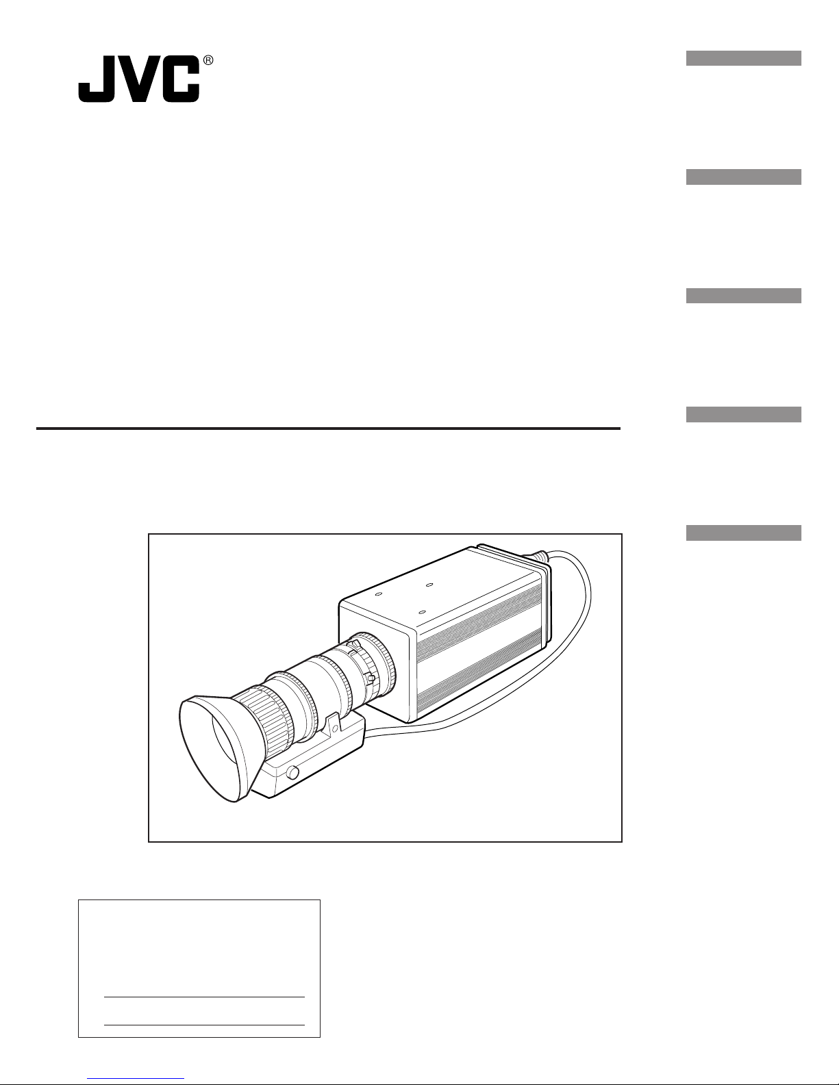
3CCD Digital Camera
3CCD Digitale Kamera
3CCD Caméra numérique
KY-F75
Illustration with optional lens attachment.
This instruction book is made from 100%
recycled paper.
LWT0059-001A
For Customer Use:
Enter below the Serial No. which is
located on the unit. Retain this
information for future reference.
Model No. KY-F75
Serial No.
Introduction
Preparations
Recording
Settings
Others
Page 2
1. Read all of these instructions.
2. Save these instructions for later use.
3. All warnings on the product and in the operating instructions should be adhered to.
4. Unplug this appliance system from the wall outlet before cleaning. Do not use liquid
cleaners or aerosol cleaners. Use a damp cloth for cleaning.
5. Do not use attachments not recommended by the appliance manufacturer as they may
cause hazards.
6. Do not use this appliance near water - for example, near a bathtub, washbowl, kitchen
sink, or laundry tub, in a wet basement, or near a swimming pool, etc.
7. Do not place this appliance on an unstable cart, stand, or table. The
appliance may fall, causing serious injury to a child or adult, and
serious damage to the appliance.
Use only with a cart or stand recommended by the manufacturer, or
sold with the appliance. Wall or shelf mounting should follow the
manufacturer’s instructions, and should use a mounting kit approved
by the manufacturer. An appliance and cart combination should be
moved with care.
Quick stops, excessive force, and uneven surfaces may cause the
appliance and cart combination to overturn.
8. Slots and openings in the cabinet and the back or bottom are provided for ventilation,
and to insure reliable operation of the appliance and to protect it from overheating,
these openings must not be blocked or covered. The openings should never be blocked
by placing the appliance on a bed, sofa, rug, or other similar surface.
This appliance should never be placed near or over a radiator or heat register. This
appliance should not be placed in a built-in installation such as a bookcase unless
proper ventilation is provided.
9. This appliance should be operated only from the type of power source indicated on the
marking label. If you are not sure of the type of power supplied to your home, consult
your dealer or local power company. For appliance designed to operate from battery
power, refer to the operating instructions.
10. This appliance system is equipped with a 3-wire grounding type plug (a plug having a
third (grounding) pin). This plug will only fit into a grounding-type power outlet. This is a
safety feature. If you are unable to insert the plug into the outlet, contact your electrician
to replace your obsolete outlet. Do not defeat the safety purpose of the grounding plug.
11. For added protection for this product during a lightning storm, or when it is left unattended
and unused for long periods of time, unplug it from the wall outlet and disconnect the
antenna or cable system. This will prevent damage to the product due to lightning and
power-line surges.
12. Do not allow anything to rest on the power cord. Do not locate this appliance where the
cord will be abused by persons walking on it.
IMPORTANT SAFEGUARDS
PORTABLE CART WARNING
(symbol provided by RETAC)
S3126A
I
Page 3

13. Follow all warnings and instructions marked on the appliance.
14. Do not overload wall outlets and extension cords as this can result in fire or electric
shock.
15. Never push objects of any kind into his appliance through cabinet slots as they mat
touch dangerous voltage points or short out parts that could result in a fire or electric
shock. Never spill liquid of any kind on the appliance.
16. Do not attempt to service this appliance yourself as opening or removing covers may
expose you to dangerous voltage or other hazards. Refer all servicing to qualified service
personnel.
17. Unplug his appliance from the wall outlet and refer servicing to qualified service personnel
under following conditions:
a. When the power cord or plug is damaged or frayed.
b. If liquid has been spilled into the appliance.
c. If the appliance has been exposed to rain or water.
d. If the appliance does not operate normally by following the operating instructions.
Adjust only those controls that are covered by the operating instructions as improper
adjustment of other controls may result in damage and will often require extensive
work by a qualified technician to restore the appliance to normal operation.
e. If the appliance has been dropped or the cabinet has been damaged.
f. When the appliance exhibits a distinct change in performance - this indicates a
need for service.
18. When replacement parts are required, be sure the service technician has used
replacement parts specified by the manufacturer that have the same characteristics as
the original part. Unauthorized substitutions may result in fire, electric shock, or other
hazards.
19. Upon completion of any service or repairs to this appliance, ask the service technician
to perform routine safety checks to determine that the appliance is in safe operating
condition.
II
(FOR USA AND CANADA) Note for Accessory options.
AA-P700MDU AC Adaptor is designed to use in Hospital or other
Medical usage.
AA-P700U AC Adaptor is designed to use for non Medical usage.
Please use for appropriate AC Adaptor for your system.
Page 4

1. JVC PROFESSIONAL PRODUCTS (U.K.)
LIMITED
ULLSWATER HOUSE, KENDAL AVENUE
LONDON, W3 0XA, UNITED KINGDOM
TEL : 020 8896 6000
2. JVC PROFESSIONAL PRODUCTS GMBH
GRÜENER WEG 10, 61169 FRIEDBERG /
HESSEN GERMANY
TEL : (06031)6050
3. JVC PROFESSIONAL PRODUCTS
ITALIA S.p.A.
VIA MARIO PANNUNZIO 4, 20156
MILANO, ITALY
TEL : (02)38.05.01
4. JVC FRANCE S.A.
1, AVENUE EIFFEL 78422 CARRIERESSUR-SEINE, CEDEX FRANCE
TEL : 1.61.04.11.64
5. JVC ESPAÑA S.A.
CTRA GRACIA MANRESA,KM 14 750
EDIFICIO CAN CASTANYER
08190 SANT CUGAT DEL VALLES
(BARCELONA) SPAIN
TEL : (93)5653210
6. JVC BELGIUM S.A./N.V.
RUE DE LA PETITE LLE 3, KLEINEILANDSTRAAT,
BRUXELLES 1070 BRUSSEL, BELGIUM
TEL : (02)529-4211
7. JVC NEDERLAND B.V.
JVC PLEIN DE HEYDERWEG 2, 2314 XZ
LEIDEN, NEDERLAND
TEL : (071)5453333
III
JVC Sales Office
8. JVC SVENSKA AB
VEDDESTAVAGEN 15, S-175 62
JARFALLA-STOCKHOLM, SWEDEN
TEL : (08)7950400
9. JVC NORGE A/S
P.O.BOX 2012, POSTTERMINALEN 3103,
TONSBERG, NORWAY
TEL : (333)61600
10. JVC DENMARK A/S
HELGESHOJ ALLE 30 DK-2630,
TASTRUP, DENMARK
TEL : (43)509000
11. SPITZER ELECTRONIC AG
MUHLEMATTSTRASSE 13, 4104
OBERWIL, SWITZERLAND
TEL : 0614051111
12. OY HEDPRO AB
LAUTTASAARENTIE 50, FIN-00200
HELSINKI, FINLAND
TEL : 96828244
13. ELECTROINDUSTRIAL HELLAS S.A.
62, PIRAEUS AVE, 183 46 MOSCHATO,
ATHENS, GREECE
TEL : (01)4832855
14. ORIELA S.A.
CAMPO STA. CLARA 160-A, 1100 LISBOA
PORTUGAL
TEL : 1-882-3382
15. FACO HF
FAXAFEN 12, P.O.BOX 442, 108 108
REYKAJVIK, ICELAND
TEL : 91-588-3050
JVC PROFESSIONAL PRODUCTS COMPANY
1700 VALLEY ROAD, WAYNE, NJ 07470, U.S.A.
TEL : (973)315-5000
JVC CANADA INC.
21 FINCHDENE SQUARE, SCARBOROUGH,
ONTARIO M1X 1A7, CANADA
TEL : (416)293-1311
Page 5
IV
For Sweden
VARNING
Explosionsfara vid felaktigt batteribyte.
Använd samma batterityp eller en ekvivalent typ
som rekommenderas av apparattillverkaren.
Kassera använt batteri enligt fabrikantens
instruktion.
For Norway
ADVARSEL
Lithiumbatteri – Eksplosjonsfare.
Ved utskifting benyttes kun batteri som anbefalt
av apparatfabrikanten.
Brukt batteri returneres apparatieverandøren.
For Denmark
ADVARSELI
Lithiumbatteri – Eksplosionsfare ved fejlagtig
håndtering.
Udskiftning må kun ske med batteri af samme
fabrikat og type.
Lever det brugte batteri tilbage til leverandøren.
For Finland
VAROITUS
Paristo voi räjähtää, jos se on virheellisesti
asennettu.
Vaihda paristo ainoastaan laltevalmistajan
suoaittelemaan tyyppiin. Hävitä käytetty paristo
valmistajan ohjeiden mukaisesti.
SAFETY PRECAUTIONS
FOR USA AND CANADA
This symbol indicates type B
equipment classified in accordance with IEC Publication.
601-1 Safety of medical electrical equipment.
®
MEDICAL ELECTRICAL EQUIPMENT
WITH RESPECT TO ELECTRICAL SHOCK, FIRE,
MECHANICAL AND OTHER SPECIFIED HAZARDS
ONLY IN ACCORDANCE WITH
UL.2601-1, CAN/CSA C22.2 NO.601.1
56PA
AA-P700MD AC Adaptor is designed to use in Hospital or other Medical usage.
AA-P700 AC Adaptor is designed to use for non
Medical usage.
Please use for appropriate AC Adaptor for your system.
The use of ACCESSORY equipment not complying
with the equivalent safety requirements of this equipment may lead to a reduced level of safety of the
resulting system. Consideration relating to the choice
shall include:
- use of the accessory in the PATIENT VICINITY
- evidence that the safety certification of the ACCESSORY has been performed in accordance
to the appropriate IEC 601-1 and/or IEC 601-1-1
harmonized national standard.
Page 6
E2
Thank you for purchasing the JVC KY-F75
Digital Camera.
These instructions are for KY-F75U.
The instructions are given in three languages:
English from page E2 to E47
German from page G2 to G47
French from page F2 to F47
SAFETY PRECAUTIONS
FOR USA AND CANADA
The lightning flash with arrowhead symbol,
within an equilateral triangle is intended to
alert the user to the presence of uninsulated “dangerous voltage” within the product’s
enclosure that may be of sufficient magnitude to constitute a risk of electric shock to
persons.
The exclamation point within an equilateral
triangle is intended to alert the user to the
presence of important operating and maintenance (servicing) instructions in the literature accompanying the appliance.
CAUTION: TO REDUCE THE RISK OF ELECTRIC SHOCK,
DO NOT REMOVE COVER (OR BACK).
NO USER SERVICEABLE PARTS INSIDE.
REFER SERVICING TO QUALIFIED SERVICE
PERSONNEL.
Information for USA
This device complies with Part 15 of the FCC Rules.
Changes or modifications not approved by JVC could
void the user’s authority to operate the equipment.
INFORMATION (FOR CANADA)
RENSEIGNEMENT (POUR CANADA)
• This Class B digital apparatus complies with Canadian ICES-003.
• Cet appareil numérique de la classe B est conforme
à la norme NMB-003 du Canada.
Changes or modifications not approved by JVC could
void the user’s authority to operate the equipment.
WARNING:
TO REDUCE THE RISK OF FIRE OR ELECTRIC
SHOCK, DO NOT EXPOSE THIS APPLIANCE
TO RAIN OR MOISTURE.
This unit should be used with 12V DC only.
CAUTION:
To prevent electric shocks and fire hazards, do NOT use
any other power source.
Due to design modifications, data given in this
instruction book are subject to possible
change without prior notice.
CAUTION:
To prevent electric shock, do not open the cabinet. No
user serviceable parts inside. Refer servicing to qualified service personnel.
This unit is designed for professional use only.
RISK OF ELECTRIC SHOCK
DO NOT OPEN
CAUTION
WARNING:
Disporsal of product should follow National, State and
Local Laws.
Page 7

E3
SAFETY PRECAUTIONS
This equipment is in conformity with the provisions and protection requirements of the corresponding European Directives. This equipment is designed for professional video appliances
and can be used in the following environments.
• residential area (in houses) or rural area
• commercial and light industry; e.g. offices or theatres
• urban outdoors
In order to keep the best performance and furthermore for electromagnetic compatibility we recommend to use cables not exceeding the following length:
Caution : Where there are strong electromagnetic waves or magnetism, for ex-
ample near a radio or TV transmitter, transformer, motor, etc., the picture may be disturbed. In such case, please keep the apparatus away
from the sources of the disturbance.
Port Cable Length Port Cable Length
DC IN Exclusive Cable 2 meters REMOTE Single wire 5 meters
LENS Cable of LENS 0.4 meter IEEE1394 IEEE1394 Cable 4.5 meters
Page 8

E4
Contents
1. Introduction
Features .................................................... 5
Accessories and attachments ................... 5
Cautionary notes for the correct usage of
this product ............................................... 6
Part names and their functions ................. 7
Pin configurations of connectors ............... 8
2. Preparations
System .................................................... 10
Preparing the computer .......................... 12
Connection to computer .......................... 14
Mounting and setting the lens ................. 15
Connecting the AC adapter ..................... 16
Mounting the camera .............................. 18
Fall prevention ......................................... 19
3. Recording
How to record .......................................... 20
Starting the [KY-LINK] application
software ................................................... 21
Freezing the image ................................. 22
Capturing the still image
on the computer (Capture) ...................... 23
Characters and symbols used in this instruction book
CAUTION Cautionary notes concerning operation of the unit
MEMO Reference such as restrictions of features, etc.
墌 Reference page or item
In general, the names of products manufactured by other companies and mentioned in these
instructions are trademarks or registered trademarks of these companies.
Symbols like , , , etc., are not used in these instructions.
4. Settings
Opening and closing
the Settings screen ................................. 24
Exposure settings screen ........................ 26
White balance settings screen ................ 30
Performing Auto white balance ............... 33
Adjustment of white shading ................... 34
Process settings screen .......................... 35
White spot compensation ........................ 38
Color matrix settings screen ................... 39
Lens settings screen ............................... 41
System settings screen ...........................42
5. Others
Synchronizing flash and trigger ............... 43
About ALC and EEI operations ............... 45
Specifications ..........................................46
Page 9
E5
Features
● The KY-F75 is a digital camera employing three 1/2” CCD with 1.45 million effective pixels.
● Output of 1360 × 1024-pixel digital video signal possible.
● Built-in DSP for real-time processing of the video signal that is output as a 7.5 frames-per-
second RGB digital signal enables real-time transfer to personal computer by means of
IEEE1394 host adapter.
● Built-in IEEE1394 connector enables remote control from personal computer. (Supplied software)
● Employment of 1/2” C-mount optical system enables connection to various types of optical
devices.
● Recording in the near-infrared region can be accomplished by replacing the optical filter (separately sold).
(Please consult the nearest JVC Service Center or your dealer with regards to replacement of
the optical filter.)
1. Introduction
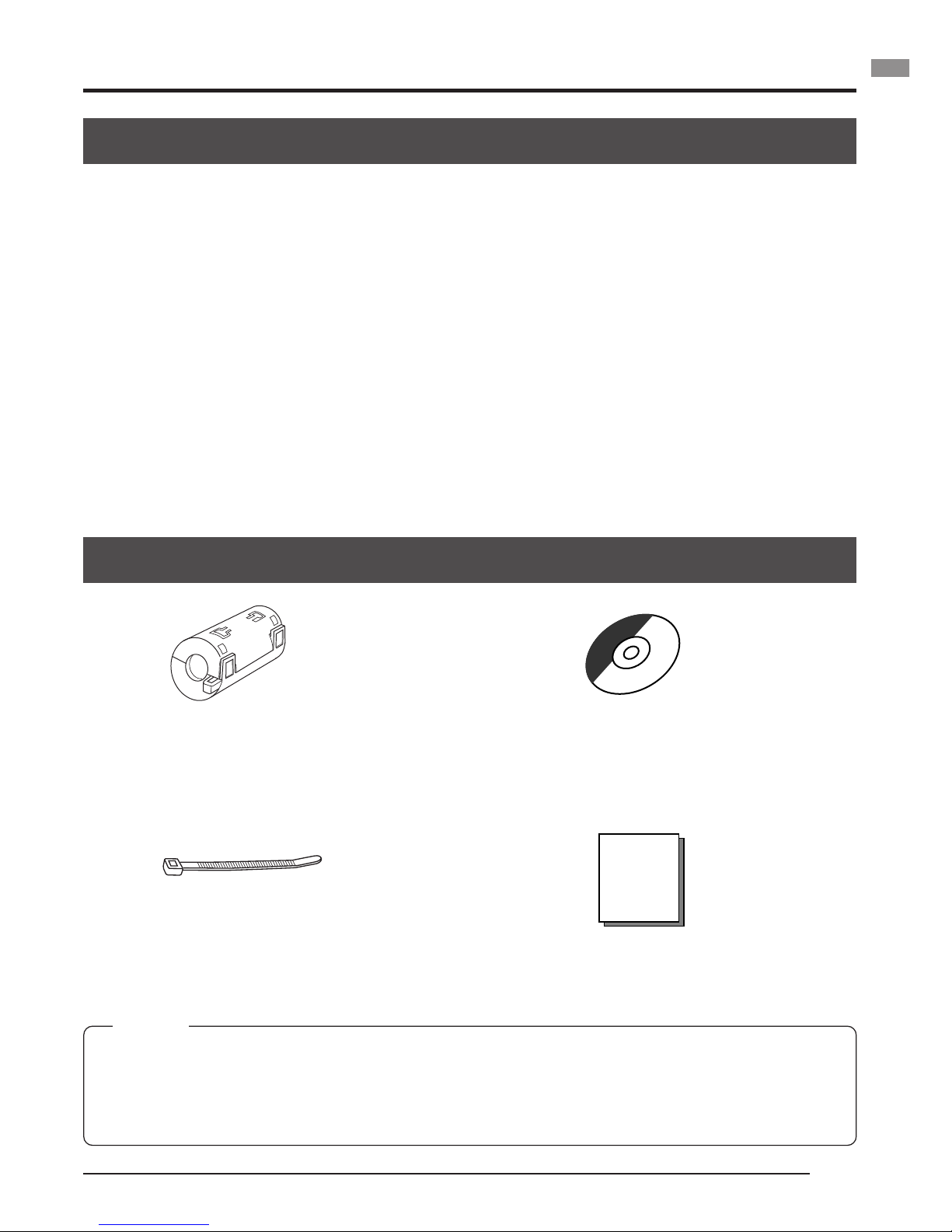
Accessories and attachments
INSTRUCTIONS
Clamp filter (2 pcs.)
For IEEE1394 cable and DC power cable
( 墌 page E14, E16)
Wire clamp (5 pcs.)
For clamping cables on the rear.
MEMO
To allow control of the camera and allow the camera image to be shown, the IEEE1394 host
adapter and the exclusive application software [KY-LINK] must be installed in the computer.
Use the separately sold KA-FW41U model as the IEEE1394 host adapter. The exclusive
application software [KY-LINK] is found on the supplied CD-ROM.
CD-ROM (1)
Exclusive application software [KY-LINK], etc.
*
See the Readme.txt file in the [ENG] folder
on the CD-ROM for details.
Page 10

E6
Cautionary notes for the correct usage of this product
• Before recording an important event, etc., always check to make sure that this product is
working properly.
• We are not liable for any missed recordings caused by malfunction of this unit, etc.
䡵 Phenomena unique to CCD
• Smearing and blooming
When using CCD to record a bright light source, a smearing effect may occur running a
white line vertical to the light source. In addition, a blooming effect may also occur when the
light source is extremely bright, spreading light to the source surroundings.
• Line distortion
Line and patterns may appear distorted when recorded.
• White spots
White spots may appear on the screen when operating under high temperatures. Always
use the product under recommended ambient temperatures.
White spots may also appear at a slow shutter speed setting (1/8 s or higher).
To reduce this phenomenon, this product is provided with at built-in white spot compensation function. ( 墌 page E38)
䡵
Cautionary notes
• Influence of strong electric waves and magnets
Screen noise and discolouration may occur when using the product near antennas of radios and televisions or near transformers, monitors, etc. with strong magnetic force.
• Compatible lenses ( 墌 page E15 Mounting and setting the lens)
Although the lens mount of this product is a type C mount, take caution as there are restrictions on the lenses that can be used.
This product is not equipped with a back-focus adjustment feature. Please use a lens
equipped with the back-focus adjustment feature.
• To save electricity, turn off the system when not in use.
• Do not leave the product where it is subject to radiation or X-rays or in locations where
corrosive gasses are generated.
䡵
Cleaning
When clean the equipment please use dry cleaning cloth or wet cleaning cloth with small
amount of alcohol.
Do not spill any liquid into KY-F75.
1. Introduction (continued)
Page 11
E7
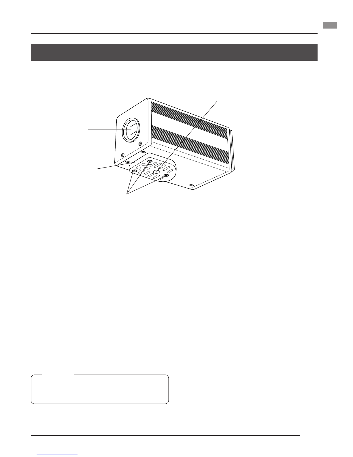
Part names and their functions
쐃 Lens mount
Although the lens mount conforms to the
type C mount lens, there are restrictions
on the lenses that can be used.
Mounting and setting the lens ( 墌 page
E15)
쐇 Camera mounting bracket
Although the mounting bracket is mounted
on the bottom of the camera when shipped,
the bracket can also be mounted on the
top of the camera.
Mounting the camera ( 墌 page E18)
쐋 Locking screws for the camera
mounting bracket
(M2.6 × 6mm, 3 units)
CAUTION
Always use the attached screws. Using screws
that exceed 6mm may result in malfunction of
the unit.
쐏 Screw holes for mounting the
camera (1/4-inch)
Used when mounting the camera to a fixer
or rotating platform.
[Front and bottom]
쐃
Page 12
E8
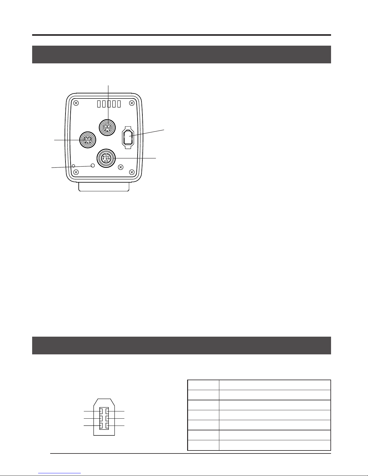
[Rear] [REMOTE] terminal
(Metal 10-pin, female)
Used to connect external devices such as
a trigger switch or flash unit.
Pin configurations of connectors ( 墌 page
E9)
[POWER] indicator
Lights when power is supplied to the camera.
[DC IN] connector
(Mini DIN 8-pin, female)
Power (DC 12V) for the camera is supplied
through this inlet.
For the power supply, use the AA-P700 AC
adapter.
Pin configurations of connectors ( 墌 page
E9)
Connecting the AC adapter ( 墌 page E16)
1. Introduction (continued)
[IEEE1394] digital output con-
nector
Digital output connector for video signal.
Used when connecting to the PC’s IEEE
1394 host adapter.
Pin configurations of connectors ( 墌 page
E8)
[LENS] connector
To connect the lens’ camera cable (for iris
control, power supply).
Pin configurations of connectors ( 墌 page
E9)
Mounting and setting the lens ( 墌 page E15)
LENS
DC IN
POWER
SEE INSTRUCTION MANUAL
REMOTE
IEEE1394
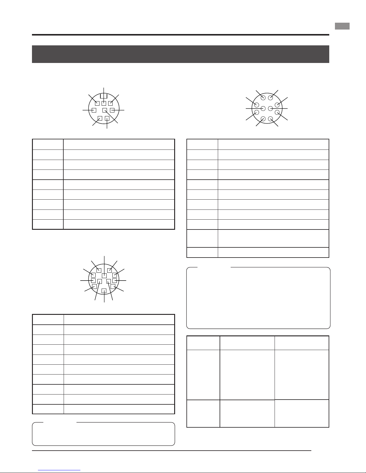
Pin configurations of connectors
Be sure to orientate all plugs correctly before inserting into the respective connectors. If the
direction of insertion is incorrect, the camera may be damaged.
IEEE 1394 connector
2
4
6
1
3
5
Pin no. Signal name
1 VP (Current)
2 VG (GND)
3 TPB –
4 TPB +
5TPA –
6TPA +
Part names and their functions (continued)
Page 13
E9
DC IN terminal (Mini DIN 8-pin, female)
Pin configurations of connectors (continued)
Pin no. Signal name
1NC
2 GND
3NC
4NC
5 GND
6 12V
7NC
8 12V
LENS terminal (Metal 12-pin, female)
Pin no. Signal name
1NC
2NC
3 GND
4NC
5 IRIS CONTROL
6 12V DC 400mA max.
7 IRIS POSITION
8 IRIS AUTO /MANU
9 to 12 NC
Terminal
name
2 TRG IN
4 FLASH
REMOTE terminal (Metal 10-pin, female)
Pin no. Signal name
1 —
2 TRG IN L active
3NC
4 FLASH OUT L active
5 —
6NC
7NC
8 GND
9 12V output
(only when power
is supplied
from AC adapter
)
10 NC
CAUTION
• Consult your JVC dealer concerning the remote terminal connection.
• Remote cable must use shielded cable.
Outer shield of remote cable must to connect
10-pin connector outer metal shell.
• Do not input the external trigger during the
first 10 seconds after the power is turned ON.
I/O
IN
• 3.3V CMOS
• Schmidt Trigger
• Pull-up to 3.3V at
4.7k Ω
OUT
• Open collector
Conditions
• Contact point
recommended
• Maximum rated
voltage: 5.3V
• H level: 2.4 ~ 5.0V
• L level: 0 ~ 0.5V
• Pulse width:
Min. 130 ms
• Maximum rated
current: 150mA
• Maximum rated
voltage: 12V
CAUTION
Use device whose current consumption is max.
400 mA or less.
1
4
3
6
7
8
5
2
1
2
8
7
10
6
3
4
5
9
4
3
2
8
9
1
7
6
11
5
10
12
Compatible plug:
HR10A-10P-10P
(Hirose Electronics)
Page 14
E10
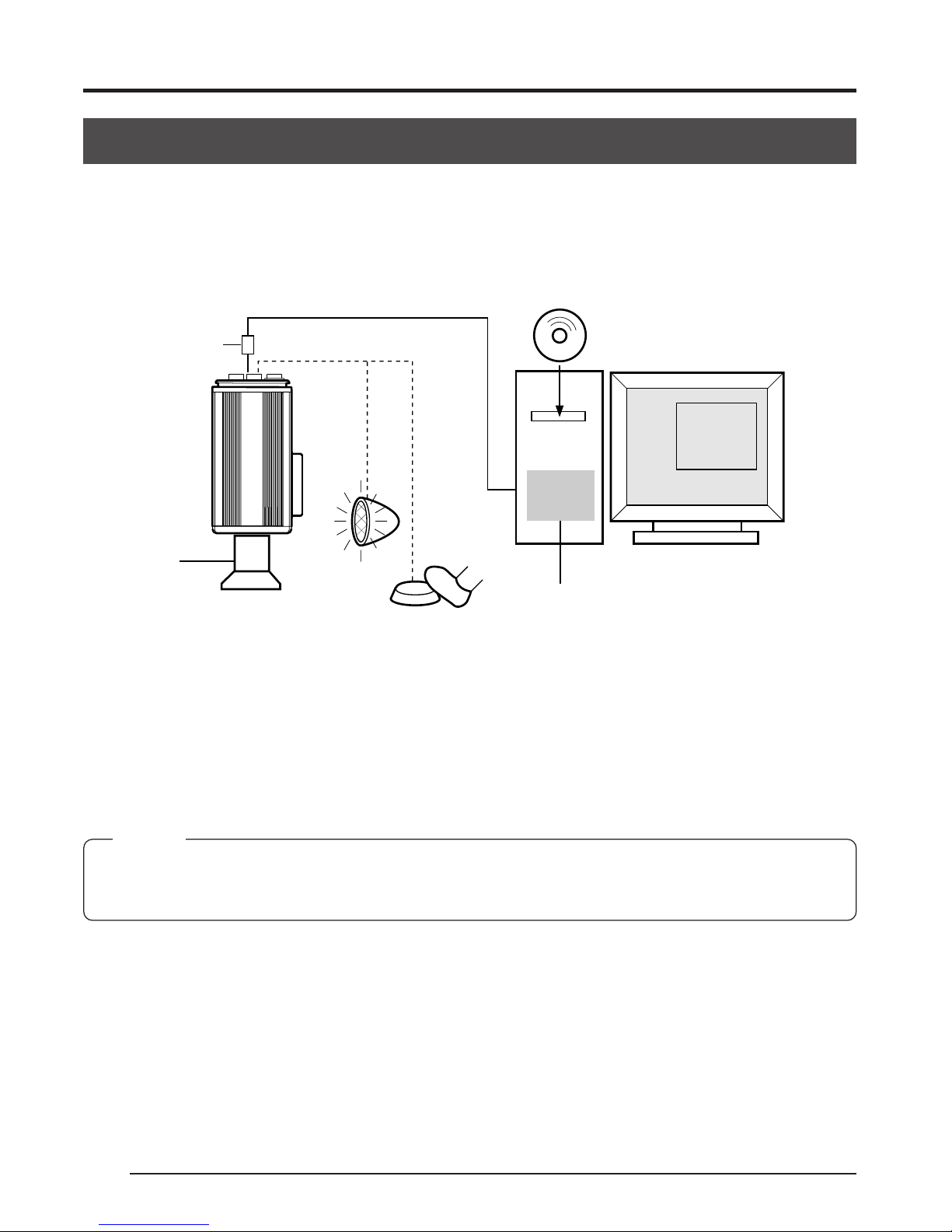
System
The KY-F75 can be remote-controlled from a personal computer, and the live image can be
shown on the computer monitor. Still images can be captured on the PC.
䡵 When using other lenses than the motorized lens
2. Preparations
[IEEE1394]
[REMOTE]
IEEE1394 cable
Supplied clamp filter
Lens
Flash
Trigger switch
KA-FW4IU (separately sold)
CD-ROM supplied with KY-F75:
Exclusive application software
[KY-LINK] and drivers for KAFW4IU
IEEE1394
Host
Adapter
PC
● Install the exclusive application software [KY-LINK] and drivers for KA-FW4IU that are included on the CD-ROM supplied with KY-F75.
● Connect the [IEEE1394] connector on the KY-F75 to the IEEE1394 PCI host adapter card on
the computer using the IEEE1394 cable. Attach the clamp filter supplied with the camera to
the IEEE1394 cable.
The power to the KY-F75 can be supplied through the IEEE1394 connector of the computer.
Caution
When the KY-F75 is supplied with power though the IEEE1394 cable, make sure that the capacity on
the supplying side is sufficient to meet the consumption by the KY-F75 (approximately 600 mA in the
case of DC 12 V).
● When required, connect a flash or trigger-switch to the [REMOTE] connector. The trigger can
also be input from the screen of the application software [KY-LINK].
The flash is fired in accordance with the input from the external trigger-switch or the trigger
input from [KY-LINK]. However, in the following cases, the flash is fired irrespective of the
trigger.
● During auto-white balance operation
● When one or more of the functions Auto Iris, EEI, and ALC is/are used
Page 15
E11
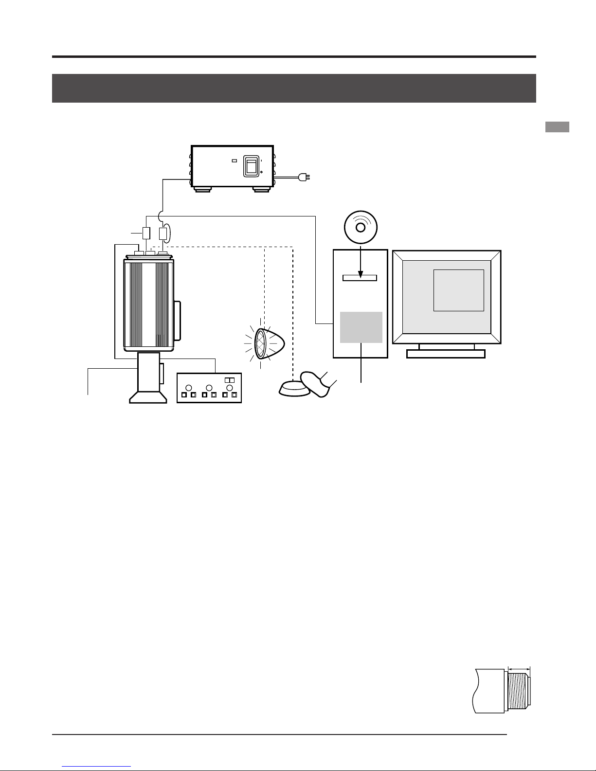
䡵 When the motorized lens is used
AC ADAPTER AA-P700
ON
OFF
POWER
AA-P700
AC
[IEEE1394]
[LENS]
[REMOTE]
[DC IN]
AC Adapter
Connect to power supply
(page. 16)
IEEE1394 cable
Supplied clamp filter
CD-ROM supplied with KY-F75:
Exclusive application software
[KY-LINK] and drivers for KAFW4IU
Control
cable
Compatible
zoom lens
Fujinon S16 × 7.3DA-DSD
Flash
Trigger switch
KA-FW4IU (separately sold)
PC
Lens remote control
Fujinon RMD-10
● Control of the motorized lens is not possible when the [IEEE1394] connector is used to supply
the power.
When the motorized lens is used, the separately sold AC Adapter AA-P700 should be used to
supply the power to the camera.
Connect the [DC IN] connector on the KY-F75 to the AA-P700 using the DC power cable.
Attach the clamp filter supplied with the KY-F75 to the DC power cable.
● Connect the camera cable from the lens to the [LENS] connector on the KY-F75.
Connect the zoom and focus control cable from the lens to the lens remote control.
● The lens control possible with this unit is only control of the iris. Control of zoom and focus
requires a separately sold lens remote control unit.
䡵 Precautions for connection
● Do not turn the AC adapter’s power switch ON or OFF, or connect or disconnect the IEEE1394
cable, while the application software [KY-LINK] is running.
● When connecting 2 or more cameras to one computer, multiple images cannot be shown at the same time.
● When using a microscope adapter, use a 1/2” C-mount adapter fitting the
microscope to be used. To reduce the risk of the adapter causing damage to
the camera, use an adapter that is 4 mm shorter than the lens mount surface.
4 mm or
shorter
Page 16

E12
2. Preparations (continued)
Preparing the computer
The camera image is displayed on the computer screen and the KY-F75 is controlled from the
computer.
䡵 There are restrictions on the computers that can be connected. See [Specifications
for connectable computer] on page E45.
䡵 To transfer the camera’s digital images to the computer, the IEEE1394 PCI host
adapter card and its driver must be installed in the computer.
● Use the following IEEE1394 PCI host adapter card:
JVC: KA-FW4IU
● The driver is found on the CD-ROM supplied with the KY-F75.
䡵 To display the camera image and control the camera, the exclusive [KY-LINK] appli-
cation software must be installed in the computer.
The [KY-LINK] application software is found in the CD-ROM supplied with the KYF75.
Page 17

E13
Installation procedure
1.
Install the IEEE1394 host adapter card KA-FW4IU and the drivers before installation of the
[KY-LINK] application software.
● For how to install the KA-FW4IU, refer to the instructions for the KA-FW4IU. Also, for
installation of the driver, see the Readme file on the CD-ROM supplied with the KY-F75.
2.
Install of the [KY-LINK] application software as follows.
햲 Insert the CD-ROM supplied with the KY-F75 into the computer’s CD-ROM drive.
햳 Select the \ENU\Kylink folder on the CD-ROM, and double-click Setup.exe.
햴 The setup screen appears. Follow the instructions on the screen to execute the setup.
햵 When the setup is completed, the application software [KY-LINK] will be ready to use
after the computer has been restarted.
MEMO
To uninstall the [KY-LINK] application software, select Control Panel 씮 Add/Remove Programs 씮 KYLINK.
Double-click Setup.exe
Page 18

E14
2. Preparations (continued)
Connection to computer
Connect the KY-F75’s IEEE1394 connector to the IEEE1394 host adapter card with the IEEE1394
cable.
䡵 Attaching the clamp filter
● To reduce the emission of unwanted radio waves,
make sure to attach the provided clamp filter to
the IEEE1394 cable as shown in the figure on the
left.
● Attach the clamp filter as close as possible to the
KY-F75.
䡵 The power to the KY-F75 can be supplied through the IEEE1394 connector of the
computer. However, the following precautions must be adhered to.
Precautions on power supply
• When supplying the KY-F75 with power though the IEEE1394 cable, make sure that the capacity on
the supplying side is sufficient to meet the consumption by the KY-F75 (approximately 600 mA in the
case of DC 12 V).
When supplying the KY-F75 with power from the computer, make sure that sufficient power is supplied to the power supply connector of the IEEE1394 host adapter card.
For details, see the instructions for the IEEE1394 host adapter card.
• When the motorized lens is used, make sure to supply the power from the camera’s [DC IN] connector.
LENS
DC IN
POWER
SEE INSTRUCTION MANUAL
REMOTE
IEEE1394
IEEE1394
Host
Adapter
PC
KY-F75 rear panel
IEEE1394 cable
To [IEEE1394]
connector
Page 19

E15
Mounting and setting the lens
Follow the procedure shown below when mounting a motorized lens. For further details, see the
instruction manual for the lens and the lens remote control.
2.
Camera head
Thread
section
Mount clamp ring
Lens
3.
Lock
Compatible zoom lens
Fujinon S16 × 7.3DA-DSD
Lens remote control
Fujinon RMD-10
RMD-20
4.
Lock
(female)
Lens remote
control
1.
Remove the lens mount cap. At this time, ensure
that dust do not enter inside the mount.
2.
To mount the lens, lightly press the thread section of the lens mount onto the thread section
of the camera, and then turn the lens unit or the KY-F75 slowly clockwise until the lens is
securely threaded onto the camera.
MEMO
To change the position of the lens rotation:
햲 First, turn the mount clamp ring clockwise (1/4 turn) as seen from the front of the lens.
햳 Slowly turn the lens to adjust its position, and then retighten the mount clamp ring.
3.
Insert the plug of the camera cable from the lens into the [LENS] connector on the rear
panel of the KY-F75. Rotate the plug until it is securely locked.
Control of the iris is performed from the KY-F75.
4.
When connecting to the lens remote control, connect the plug (female) of the lens control
cable to the remote control.
5.
Make settings on the setting screen of the application software [KY-LINK] in accordance
with the used lens.
䡵 Iris mode settings on the Exposure and Lens setting screens ( 墌 page E26, E41)
● When using a motorized lens, set to AUTO as iris control is performed automatically.
● When using a manual lens, or for manual iris control on the camera when using a
motorized lens, set to MANUAL.
● When performing iris control with the lens remote control, set to MANUAL.
CAUTION
When using a motorized lens, supply power to the camera from an AC adapter. Control of the motorized
lens is not possible when power is supplied through the [IEEE1394] connector.
CAUTION
● Perform mounting of the lens with
the power of the camera turned
OFF. Mounting with the power on
could result in damage.
● Lens is not included with this
camera.
To avoid damaging the camera,
make sure that the lens mount of
the lens to be used is 4mm or less.
4 mm or
shorter
Lens
(male)
Page 20

E16
2. Preparations (continued)
Connecting the AC adapter
It is possible to supply power to the KY-F75 from the computer via the IEEE1394 cable, but when
a motorized lens, etc., is used, the DC cable should be used to connect the KY-F75’s [DC IN]
connector and the [TO CAMERA] connector on the AC adapter (AA-P700).
CAUTION
• Be sure to use the AA-P700 AC adapter.
Make sure that the power switch on the AA-P700 AC adapter is set to OFF before connections are
made. Making connections while the power is ON could result in damage to the KY-F75.
䡵 Connecting the DC power cable and attaching the filter clamp
● After inserting the plug completely, tighten the se-
curing ring
● To reduce the emission of unwanted radio waves,
make sure to attach the provided clamp filter as
shown in the figure on the left. Wind the cable once
around the clamp filter.
● Attach the clamp filter as close as possible to the
KY-F75 as shown in the figure.
VIDEO OUTPUT
TO CAMERAS(Y/C) OUTPUT
DC 12V=OUTPUT
EITHER
OUTPUT
MAX 1.25A
SEE INSTRUCTION
MANUAL
AC 100V
AA-P700
LENS
DC IN
POWER
SEE INSTRUCTION MANUAL
REMOTE
IEEE1394
AC adapter (separately sold)
DC cable (2 m)
(separately sold)
White marking
Connect the end with the
white marking to the AC
adapter
TO CAMERA
connector
DC IN connector
Clamp filter
(supplied)
DC IN
POWER
DC IN
DC IN
Plug
Ring
Clamp filter
Page 21

E17
䡵 Turning the power ON
Wait for 5 seconds or more after the power switch on the AA-P700 is set to ON before invoking the [KY-LINK] application software.
䡵 Turning the power OFF
Wait for 5 seconds or more after the [KY-LINK] application software is closed before setting
the power switch on the AA-P700 to OFF.
CAUTION
• After the power switch has been turned OFF, wait at least 10 seconds before turning the power ON
again. Turning the power switch ON/OFF in rapid succession may result in malfunctions, such as
failure to boot, etc.
• When power is supplied from the computer, control of the motorized lens is not possible.
MEMO
If power is supplied from both the IEEE1394 connector and from the DC IN connector, the DC IN
connector will have priority.
Page 22

E18
Mounting the camera
● When mounting the camera, use the camera mount screw hole located on the camera mounting bracket.
● When mounting the camera, use the rotation prevention hole to prevent the unit from falling
and securely mount the unit.
< Changing the camera mounting bracket position >
< Mounting method >
Rotation prevention hole
Camera mounting screw hole
Camera mounting bracket
When shipped, the camera mounting bracket
is mounted on the bottom of the unit. To mount
it on the top of the unit, simply remove the 3
locking screws holding the camera mounting
bracket.
CAUTION
Always use the attached screws. Using screws
that exceed 6mm may result in malfunction of
the unit.
2. Preparations (continued)
Page 23

E19
Fall prevention
Fall prevention
wire chain
Camera head
MEMO
• Special attention is required when mounting the unit to the wall or ceiling. Rather
than attempting to do it yourself, request a qualified person to perform such installation. Falling of the unit may result in bodily injury.
• To prevent the unit from falling, connect the unit to a strong surface with a wire
chain, etc. When connecting such chain, use the bracket locking screw hole on the
side which the camera mounting bracket is not mounted. (M2.6 × 6mm)
Take special caution to the length of the optional wire as well.
• For the fall-preventive wire, use the one with the strength that is more than 10 times
of a mass including the lens.
6 mm
Page 24

E20
How to record
Operations for the various settings of the KY-F75 and camera recording are performed using the
[KY-LINK] application software.
Digital images are transferred from the camera to the computer at a rate of 7.5 frames per
second. When a footswitch or other external trigger device is connected to the KY-F75, the
camera image can be frozen by the external trigger input signal.
Basic operations for recording
1.
Turn ON the KY-F75.
Wait for 5 seconds or more.
2.
Start the [KY-LINK] application software.
䡵 Make camera settings as required. Menu screen settings ( 墌 page E24)
䡵 Freeze the image as required. (Still image)
3.
Capture the still image on the computer (Capture)
4.
Save the captured image on the computer.
5.
Close the [KY-LINK] application software.
Wait for 5 seconds or more.
6.
Turn OFF the KY-F75.
3. Recording
Page 25

E21
Starting the [KY-LINK] application software
䡵 Wait for 5 seconds or more after turning the KY-F75 ON before starting up the KY-
LINK software.
1.
Starting KY-LINK
Select [Start] 씮 [Programs] 씮 [KY-LINK] 씮 [KY-LINK].
● The KY-LINK start screen appears.
KY-LINK start screen
2.
Select Camera, and then click the [OK] button.
● The selected camera image is displayed.
(Live image is shown at a rate of 7.5 frames per second.)
MEMO
For details on the operation of the [KY-LINK] application software, see the Help file for the [KY-LINK]
application software.
This manual only explains the broad outlines of the operation.
Page 26

E22
Freezing the image
Live image is shown on the monitor at a rate of 7.5 frames per second.
The following describes the procedure for freezing a required image. (Still image displayed)
1.
The image is frozen when the [Freeze/Cancel] button is clicked. (Still image displayed)
2.
To stop display of the frozen image, click the Freeze button again.
When an external trigger device is connected
The frozen image can be turned ON/OFF by the trigger input through the [REMOTE] connector
on the KY-F75.
Interlocking with the flash
When a flash is connected to the [REMOTE] connector on the KY-F75, the flash can be made to
fire in synch with KY-LINK freeze operation or the external trigger input. ( 墌 page E43)
However, in the following case, the flash will fire irrespective of the trigger.
● During auto white balance operation
● When one or more of the functions auto iris, EEI, and ALC is/are used
MEMO
The freeze function of the KY-F75 is accomplished in the memory of the computer by stopping the
output of the camera image. Accordingly, if the trigger is input to the camera while the live-window is not
shown, an image will not appear even if the live-window is displayed.
3. Recording (continued)
Tool bar
[Freeze/Cancel]
button
Living image
Page 27

E23
Capturing the still image on the computer (Capture)
䡵 Click the Capture button in the toolbar.
● The still image is captured and the captured image is displayed.
Saving the captured image on the computer
䡵 Click the [Save As] button, and then give the image a name and save the file.
Closing the KY-LINK application
䡵 Select [Exit] from the File menu.
Caution
• Wait for 5 seconds or more after closing the [KY-LINK] before turning the KY-F75 OFF.
• Do not turn OFF the power to the camera while the [KY-LINK] is running.
Capture button
[Single Capture], [Multi Capture], [Timer Capture
Set/Reset], [Trigger Capture Set/Reset]
[Save As] button
File
[Exit]
Page 28

E24
Opening and closing the Settings screen
The various camera settings are performed on the computer screen using the [KY-LINK] application software. The settings valid when the [KY-LINK] is closed are automatically recalled and
set in the camera the next time the system is started up.
Procedure
1.
Turn ON the KY-F75 and wait for 5 seconds or more.
2.
Start up the [KY-LINK] application software. ( 墌 page E21)
3.
Open the Settings screen.
● The Settings screen is displayed by clicking the [Show Control Window] button in the KYLINK screen.
4. Settings
Settings screen
Categories selection tab
The Settings screen consists of 6 different categories of setting screens.
● Exposure: Used for image level related settings such as Iris, Shutter, Gain, etc.
● White balance: Used for settings of color temperature, white balance, etc.
● Process: Used for image quality related settings such as detail compensation, gamma,
white spot compensation, etc.
● Color matrix: Used for settings related to
color tone.
● Lens: Used for setting of the method for control of the lens iris.
● System: Used for setting the method for releasing the freeze mode, setting the test
pattern level, and for settings related to
memorization of the setting values.
4.
Selecting the Setting screen
● Click the selection tab corresponding to the category to be set.
The selected Settings screen appears.
[Show Control window] button
Page 29

E25
5.
Set the items on the Settings screen.
For settings on the various setting screens, see pages E26 to E42.
6.
Completing the settings on the Settings screen.
Click the [X] (Close) button.
——— Saving the setting values on the computer ———
● Save the setting values as a file on the computer by selecting [File] 씮 [Save].
● Read out the setting values saved on the computer by selecting [File] 씮 [Load].
(To return the setting values to the factory defaults, read in “DefaultF75.dat”.)
[Close] button
File
[Load], [Save]
Page 30

E26
Exposure settings screen
This screen is used to make settings related to the image level, such as Iris, Shutter, and Sensitivity.
4. Settings (continued)
Shutter settings
Restart button
Valid when the
shutter speed is 2
sec or slower in the
V. SCAN mode.
Iris settings
Gain settings
EEI limit setting
Sets the slowest shutter
speed when the shutter
mode is EEI.
ALC max settings
Sets the maximum ALC
sensitivity.
Level settings
Set the level by sliding the
slider bar with the mouse.
Also, fine adjustment can
be made with the
keyboard’s [씯] and [씮]
keys.
For selecting the setting value
Select the setting value
from the pull-down menu.
Page 31

E27
Contents
Switched in accordance with the used lens.
AUTO: When using auto-iris.
MANUAL: • When using manual iris lens.
• Lens not mounted
•
When using manual iris while motorized lens is mounted.
*
When the motorized lens cable is not connected to the [LENS]
connector, the setting automatically becomes “MANUAL”.
Used to set the iris level when the Iris mode is set to
“MANUAL”. When an motorized lens is used, this sets the
iris level when manual iris control on the camera is used.
Increasing the value: Open the iris
Decreasing the value: Closes the iris
Used to adjust the video level when auto-iris, ALC and EEI are used,
Increasing the value: Raises the level
Decreasing the value: Lowers the level
Selects the detection area for the image level when Auto
Iris, ALC or EEI is used. When selected, the detection
area is shown on the screen.
Selects the detection method of the detection area when
Auto Iris, ALC, or EEI is used.
NORMAL: normal positon
PEAK: detects the peak brightness level for better
view of highly bright objects.
AVG: detects the avarage brighhtness for better
view of objects.
Item
Iris mode
Set Value
[AUTO]
MANUAL
0
1
•
[128]
•
254
255
– 128
– 127
:
[NORMAL]
:
126
127
SQUARE
SPOT
[FULL]
CIRCLE
[NORMAL]
PEAK
AVG
Iris level
AE level
AE area
AE detect
MEMO
“----“ is displayed when auto-iris, ALC, and EEI are all set to
not operate.
Detection
area
Detection
area
Detection area
Detection
area
SPOT
CIRCLE
FULL
SQUARE
MEMO
During display of the detection area, operation of the Auto
Iris, ALC, and EEI is inhibited.
MEMO
AE area and AE detect are not shown when none of the functions Auto Iris, ALC, or EEI is used.
[ ] indicates the factory setting
Page 32

E28
Speed
When “STEP”
is selected
Speed
When
“V.SCAN” is
selected
Speed
When
“RANDON” is
selected
Restart
Contents
Used to switch the shutter mode.
STEP: The shutter speed can be changed with the
[Speed] item.
V. SCAN: The shutter speed can be changed with the
[Speed] item.
Enables more detailed setting than [STEP].
EEI:
Used to automatically change the shutter speed
in accordance with the brightness of the subject
.
OFF: Fixed at 1/7.5 s.
RANDOM: Used to synchronize the CCD accumulation
timing with the Trigger input.
The shutter speed can be changed with the
[Speed] item.
The shutter speed can be changed when Shutter is set to
“STEP”, “V.SCAN” or “RANDOM”.
When the accumulation time exceeds 2 seconds in the V.
SCAN mode, click to reset the CCD integration.
This button is only valid when V. SCAN is selected on the
Shutter screen and the Speed item is set to 2s or slower.
MEMO
When clicked, the images accumulated by the CCD up to that
point are output.
Item
Shutter
4. Menu screen settings (continued)
Set Value
[STEP]
V.SCAN
EEI
OFF
RANDOM
4s
2s
1s
1/2s
1/4s
[1/8s]
1/15s
1/30s
1/60s
1/125s
1/250s
1/500s
1/1000s
1/2000s
4.010s
•
[1/7.501s]
•
•
1/5906.836s
1/7.501s
•
[1/124.176s]
•
•
1/5648.194s
——
MEMO
• When the shutter speed is slower than 1/7.5 s, the following phenomena may occur.
• Time will be required for the auto white, auto iris and
ALC operations.
If the shutter speed is set to 2 sec or longer, these operations will behave as follows. (However, 1.000 sec or
longer at the time of V.SCAN.)
Auto white : Auto white balance function cannot be
started.
Auto iris : Stops at the iris value at that time.
ALC : Stops at the sensitivity at that time.
To use a shutter speed of 2 sec or longer, use with the
following settings selected: (However, 1.000 sec or longer
at the time of V.SCAN.)
Iris mode : MANUAL
Gain : STEP or V.GAIN
• There may be shortage of light when the shutter speed
is increased. In this case, adjust the iris or sensitivity.
Attention should be paid to the picture quality when the
sensitivity is raised since the image becomes coarse.
Exposure settings screen (continued)
[ ] indicates the factory setting
Page 33

E29
Contents
Used to switch the sensitivity mode.
STEP: The sensitivity can be changed with the “Level”
item.
ALC: The sensitivity is automatically changed in ac-
cordance with ambient brightness.
V.GAIN: The sensitivity can be changed in detail with
the “Level” item.
Sets the maximum sensitivity of ALC, which automatically
switches the sensitivity in accordance with ambient brightness.
Sets the minimum value for the shutter speed when the
shutter mode is set to “EEI”.
1/7.5s: Set to 1/7.5s.
1s: Set to 1s.
Item
Gain
Level
When
“STEP” is
selected
Level
When
“V. GAIN” is
selected
ALC max
EEI limit
Set Value
[STEP]
ALC
V.GAIN
[0dB]
+6dB
+12dB
[0.0dB]
+0.2dB
+0.4dB
•
•
+12dB
[+12dB]
+6dB
[1/7.5s]
1s
[ ] indicates the factory setting
Page 34

E30
White balance settings screen
This screen is used to make settings related to the color temperature at the time of shooting,
white balance and white shading adjustment.
4. Settings (continued)
White shading adjustment
Even if white balance is achieved at the center
of the screen, white balance may not be achieved
at the top and bottom areas of the screen that
may be tinted by green or magenta. This is due
to lens characteristics, and compensation for this
phenomenon is called white shading.
䡵 Make this adjustment after white balance is
completed.
䡵 If white shading adjustment is performed,
perform white balance adjustment again.
Auto white button:
Click this button when auto
white balance adjustment
should be performed.
Sets the standard color temperature
for the white balance adjustment.
White balance adjustment
As the color of the light (color temperature) differs with the light source, the white balance
should be readjusted when the light source illuminating the subject changes.
COLOR
TEMP
WHITE
BALANCE
3200K
2000K
PRESET
5600K
AUTO
MANUAL
PRESET
AUTO
MANUAL
3200K
5200K
5600K 15000K
COLOR TEMP
Color temperature when COLOR TEMP and WHITE BALANCE are set. * Regard the values as reference values.
Page 35

E31
Contents
Used to set the standard color temperature of the white
balance.
3200K: For use under low color temperature illumina-
tion, such as halogen lamps, etc.
5600K: For use under high color temperature illumi-
nation, such as sunlight, etc.
Used to set the white balance mode.
AUTO1,
Select this setting when white balance adjustment
should be operating. Two white balance adjustment modes are provided (AUTO1 and AUTO2).
( 墌 page E33 Performing Auto white balance)
Fine adjustment of the white accomplished by
the white balance can be made using Level
(R) and Level (B).
MANUAL: The white balance can be changed using Level
(R) and Level (B).
PRESET: The white balance is fixed at the setting
made for the [Color temp.] item.
The red color in the white balance can be adjusted when
[White bal.] is set to “AUTO “or “MANUAL”.
Increasing the value: Red tint of screen becomes stronger
Decreasing the value: Red tint of screen becomes weaker
The blue color in the white balance can be adjusted when
[White bal.] is set to “AUTO” or “MANUAL”.
Increasing the value: Blue tint of screen becomes stronger
Decreasing the value: Blue tint of screen becomes weaker
Click this button to perform auto white balance adjustment.
Item
Color
temp.
White bal.
Level (R)
When
“AUTO” is
selected.
Level (R)
When
“MANUAL” is
selected.
Level (B)
When
“AUTO” is
selected.
Level (B)
When
“MANUAL” is
selected.
Auto White
Set Value
3200K
5600K
PRESET
[AUTO 1]
AUTO 2
MANUAL
– 32
:
[0]
:
31
0
:
[128]
:
255
– 32
:
[0]
:
31
0
:
[128]
:
255
——
[ ] indicates the factory setting
AUTO2:
Page 36

E32
4. Settings (continued)
White balance settings screen (continued)
[ ] indicates the factory setting
Contents
Used to set whether to perform white shading adjustment.
OFF: no white shading adjustment
ON: the white shading can be adjusted.
The color red of the white shading is adjusted only when
Shading is set to ON.
Increase the number: paler red at the bottom of the
screen and deeper red at the top.
Decrease the number: paler red at the top of the
screen and deeper red at the
bottom.
The color green of the white shading is adjusted only when
Shading is set to ON.
Increase the number: paler green at the bottom of the
screen and deeper green at the
top.
Decrease the number: paler green at the top of the
screen and deeper green at the
bottom.
The color blue of the white shading is adjusted only when
Shading is set to ON.
Increase the number: paler blue at the bottom of the
screen and deeper blue at the
top.
Decrease the number: paler blue at the top of the screen
and deeper blue at the bottom.
Set Value
[OFF]
ON
– 128
:
[0]
:
127
– 128
:
[0]
:
127
– 128
:
[0]
:
127
Item
Shading
Level (R)
Level (G)
Level (B)
Page 37

E33
Performing Auto white balance
Two auto white balance adjustment modes (AUTO1 and AUTO2) are provided. The results of the
auto white balance procedure are stored in the AUTO1 or AUTO2 memories.
1.
Place and zoom in on a white object so that the white object is at the center of the image
(and fills 80% or more of the screen).
2.
Display the White balance screen.
3.
Set the color temperature to match the light source,
3200K: When using a light source with a low color temperature, such as a halogen lamp.
5200K: When using a light source with a high color temperature, such as sunlight.
4.
Set the White bal item to AUTO1 or AUTO2.
5.
Click the Auto white button.
● The KY-F75 automatically adjusts the white balance.
* When a slow the shutter speed has been selected, white balance adjustment may take a
while.
䡵 In accordance with the results of the auto white balance, fine adjustment can be
performed using the Level (R)/(B) slider bars.
MEMO
• When the colour temperature of the subject changes as the darkness increases, do not change the
illumination. Instead, narrow the lens iris, and take the white balance again by pressing the [Auto
White] button.
• When the shutter speed is set to 2 sec or longer, it is not possible to launch the auto white balance
function. (However, 1.000 sec or longer at the time of V.SCAN.)
Temporarily return the shutter setting to a shorter value and launch the auto white balance function,
or set the item [White bal] to “MANUAL” or “PRESET”.
• Pressing the [Auto White] button in the FREEZE condition, cancels the freeze.
• When auto white balance is started with the Auto white button, the image in the live window will
become a still picture, but this is normal.
White balance screen
Color temperature
setting
White balance
item
Auto white button
Page 38

E34
4. Settings (continued)
Adjustment of white shading
White shading can occur due to the combination of lenses and the optical system that 3CCD
cameras are equipped with.
If this happens, perform adjustment as described in the following.
1.
Shoot a white subject so that the entire screen is filled with white. (Illumination should be
uniform.)
2.
Adjust the white balance.
3.
Click the Waveform window button in the toolbar of the KY-LINK screen to display the setting screen. Click the [V] and [R] button to display the waveform of the red channel in the
vertical direction.
4.
Adjust the shutter speed, etc. until the video signal level becomes about 170 – 190.
5.
On the white balance setting screen, set the Shading item to “ON”.
6.
Adjust Level (R) to make the gradient of the waveform as small as possible.
7.
Click the [G] button on the setting screen to switch to the waveform of the green channel.
Then adjust Level (G) to make the gradient of the waveform as small as possible.
8.
Click the [B] button on the setting screen to switch to the waveform of the blue channel.
Then adjust Level (B) to make the gradient of the waveform as small as possible.
9.
When adjustment of the white shading is completed, adjust the white balance.
Waveform window button
KY-LINK screen
tool bar
Video signal level
Setting screen
R button G button B button
V button
Page 39

E35
Process settings screen
This screen is used to make settings related to the picture quality, such as detail compensation,
gamma, and white spot compensation.
Detail settings
Gamma
settings
Flare setting
DSP bypass setting
ABL setting
Nega setting
Noise sup. setting
Pixel comp setting
(White spot
compensation)
Pixel check button
Click when White spot detection
should be performed.
(When Pixel comp is ON)
Master black
setting
MEMO
The setting value is the value to be set for the input signal
level before GAMMA compensation.
Contents
Used to set whether to emphasize details.
ON: changes the detail emphasis
OFF: no detail emphasis
The emphasis level of the detail is adjusted when [Dedail]
is set to ON.
increase the number: Sharpen the detail
decease the number: Soften the detail
Adjusted when you want to reduce noise in black areas.
Noise in black areas is reduced because the frequency
characteristics of areas where the image signal level falls
below this set value are lowered. However, fine details in
areas falling below the set value will be lost.
Set Value
OFF
[ON]
– 7
– 6
•
[0]
7
[0.0%]
0.5%
:
28.0%
28.5%
(0.5% step)
Item
Detail
Level
When “ON” is
selected.
Level dep.
[ ] indicates the factory setting
Page 40

E36
4. Settings (continued)
Contents
Used to reduce noise in the video signal.
LOW/MIDDLE/HIGH : Noise reduction is performed.
Amount of reduction is increased in the order of LOW 씮
MIDDLE 씮 HIGH.
OFF: Noise reduction is not performed.
Used to set whether the gamma curve to determine the
reproduction of black is to be the standard value or
customised.
NORMAL: the gamma curve is set using the standard
value (0.45)
ADJUST: set when changing the gamma curve
The gamma curve can be adjusted only when gamma is
set to ADJUST.
Increase the number: Improves the gradation of bright
areas. However, the gradation of
black becomes poorer.
Decrease the number: Improves the gradation of black
areas. However, the gradation of
bright areas becomes poorer.
Selects whether the camera image should be negative
signal.
ON: Conversion to negative signal is made.
OFF: Conversion to negative signal is not made.
Selects whether DSP (Digital Signal Processing) should
be bypassed.
NORMAL: Not bypassed.
BYPASS: Bypassed. In this case the following setting
items are fixed as indicated and cannot be set.
• Detail: OFF
• Level dep.: – – –
• Noise sup.: OFF
• Gamma: 1.00
• Nega: OFF
• Pixel comp.: OFF
• Color matrix: OFF
Set Value
LOW
MIDDLE
HIGH
[OFF]
[NORMAL]
ADJUST
0.35
:
(0.01 step)
[0.45]
:
(0.05 step)
:
0.90
1.00
ON
[OFF]
[NORMAL]
BYPASS
Item
Noise sup.
Gamma
Level
When
“ADJUST” is
selected.
Nega
DSP bypass
MEMO
Note that details in fine sections of the image may get lost
as the noise reduction amount is increased.
Process settings screen (continued)
Page 41

E37
[ ] indicates the factory setting
Contents
Used to adjust the pedestal level (master black), which is
the standard of black when the lens is capped. To see
more details in black areas, raising the pedestal level will
brighten the entire screen.
Increasing the value: Raises the pedestal level
Decreasing the value: Lowers the pedestal level
Compensation of the black level when flaring effect
occurs and black areas are tinted with color due to
irregular reflection of light entering the lens.
Compensation of the black level of Rch
Increasing the value: Red tint becomes weaker
(Makes the compensation value larger)
Decreasing the value: Red tint becomes stronger
(Makes the compensation value smaller)
Compensation of the black level of Bch
Increasing the value: Blue tint becomes weaker
(Makes the compensation value larger)
Decreasing the value: Blue tint becomes stronger
(Makes the compensation value smaller)
Used to set whether to use automatic adjustment of the
black level in accordance with the signal level during
shooting. Use this adjustment when the black level of
the video image fluctuates.
Black level is adjusted.
Increasing the value: Lowers the black level.
(Makes the compensation value larger)
Decreasing the value: Raises the black level.
(Makes the compensation value smaller)
Selects whether or not white spot compensation should
be performed.
OFF: White spot compensation not performed.
ON: White spot compensation performed.
墌 page E38 [White spot compensation]
Click this button when White spot detection should be
performed.
Set Value
– 99
:
[0]
•
99
[ON]
OFF
– 32
– 31
•
[0]
•
31
– 32
– 31
•
[0]
•
31
[ON]
OFF
– 32
– 31
•
[0]
•
31
[OFF]
ON
——
Item
Master black
Flare
Level (R)
When
“ON” is
selected.
Level (B)
When
“ON” is
selected.
ABL
Level
When “ON” is
selected.
Pixel comp.
Pixel Check
When “ON” is
selected.
Page 42

E38
4. Settings (continued)
White spot compensation
One of the inherent, general characteristics of CCDs is that white spots may appear in the image
at slow shutter speeds or during shooting at high temperatures.
To moderate this phenomenon, this camera is provided with a white spot compensation function.
How to use
䡵 White spot detection
Because the number of spots and their size differ with the temperature and shutter speed, etc.,
it is necessary to detect the positions of the white spots under the conditions of use before the
white spot compensation is used.
1.
Set the conditions for use (shutter speed, etc.).
2.
Ensure that no light falls on the CCD by closing the lens iris, etc. (When a motorized lens is
used, the iris will be closed automatically.)
3.
Display the [KY-LINK] application software’s Process setting screen.
4.
Set the Pixel comp. item to ON.
5.
When the Pixel check button is clicked, detection of white spot positions starts. The detection may take several minutes.
6.
When the detection is completed, the [Process completed] message appears.
MEMO
• The camera’s white spot compensation function cannot compensate completely for all white spots.
White spot detection and compensation by this camera can be performed under the following conditions. White spot compensation is not possible under other conditions. Even when these conditions
are met, the properties of the white spots may prevent compensation.
Detection and compensation area: Area of 1024 × 1024 pixels at the center of the screen.
No. of detections and compensations: Within a total of 15 spots.
• The [PIXEL CHECK FAILED] message may appear if light enters the CCD while white spot detection
is being performed, or due to the conditions of the white spots. In this case, confirm that light is not
falling on the CCD. If light is not falling on the CCD but the message nevertheless appears, increase
the shutter speed one step and perform the detection again.
• During white spot detection, the image in the live window will become a still picture, but this is normal.
• When white spot compensation is carried out, the compensation of the pixel data is performed based
on surrounding pixel data, which means that accurate data may not be obtained in case of an image
with fine details.
• The result of the white spot detection is retained until the next white spot detection is performed.
Page 43

E39
Color matrix settings screen
Used to set the color tone of the camera image.
Selects the color matrix.
Slider bar:
Valid when ON is selected as the
Color matrix.
Make adjustments by dragging
the slider bars with the mouse.
Fine adjustment can be made
with the keyboard’s [씯] and [씮]
keys.
Page 44

E40
4. Settings (continued)
Contents
Used to set whether or not colour matrix values remain
standard.
ON: the colour matrix becomes available for change.
The following adjustments can only be made with
this setting.
OFF: the standard value of the colour matrix is used.
Used to adjust the R–G signal (0 ~ 25%)
Used to adjust the R–B signal (0 ~ 25%)
Used to adjust the G–R (+) signal (0 ~ 25%)
Used to adjust the G–R (–) signal (0 ~ 25%)
Used to adjust the G–B (+) signal (0 ~ 25%)
Used to adjust the G–B (–) signal (0 ~ 25%)
Used to adjust the B–R signal (0 ~ 25%)
Used to adjust the B–G (+) signal (0 ~ 25%)
Used to adjust the B–G (–) signal (0 ~ 25%)
Set Value
ON
[OFF]
[0]
1
•
•
•
31
Item
Color matrix
R – G
R – G
G – R (+)
G – R (–)
G – B (+)
G – B (–)
B – R
B – G (+)
B – G (–)
Color matrix settings screen (continued)
[ ] indicates the factory setting
Page 45

E41
Lens settings screen
Used to select the method for control of the lens iris to match the lens used.
Selects the lens Iris mode.
Iris level setting
Valid when the Iris
mode is set to
MANUAL.
Contents
Switched in accordance with the employed lens.
AUTO: When using auto-iris.
MANUAL: • When using manual iris lens.
• Lens not mounted.
• When using manual iris while motorized
lens is mounted
* When the motorized lens cable is not connected to
the [LENS] connector, the setting automatically
becomes “MANUAL”.
Used to set the iris level when the Iris mode is set to
“MANUAL”. When an motorized lens is used, this sets the
iris level when manual iris control on the camera is used.
Increasing the value: Opens the iris
Decreasing the value: Closes the iris
Set Value
[AUTO]
MANUAL
0
1
•
[128]
•
255
Item
Iris mode
Iris level
When
“MANUAL” is
selected.
[ ] indicates the factory setting
Page 46

E42
System setting screen
Used to select the method for canceling the freeze image and decide whether or not a color bar
should be displayed as test pattern. It is also used for saving the set values of the setting screens
in the memory of the KY-F75.
For selecting the method for canceling the
freeze image.
For selecting display of the color bar.
For selecting the color bar level.
Save button:
Click this button to save
the values set for the
setting screens in the
memory of the KY-F75.
However, when KY-LINK
is started up, it recalls
and sets the camera to
the values valid when it
was closed down the
previous time. Consequently, the settings
saved in the camera with
the Save button are
made invalid.
Contents
Sets the method for canceling the FREEZE when the
monitor screen is in FREEZE condition .
MANUAL : Cancelled by trigger input.
AUTO1s : Cancelled after 1 second.
AUTO3s : Cancelled after 3 seconds.
AUTO5s : Cancelled after 5 seconds.
OFF : Not cancelled.
*
When set to “AUTO” or “OFF”, the displayed screen can
be updated by trigger input during the FREEZE condition.
Selects whether or not a color bar should be displayed as
test pattern.
OFF : Color bar is not displayed. The normal video sig-
nal is shown.
BAR : Color bar is displayed.
Selects the level of the color bar signal.
255 :
Outputs a color bar signal in which the white level is 255.
213 :
Outputs a color bar signal in which the white level is 213.
Set Value
[MANUAL]
AUTO1s
AUTO3s
AUTO5s
OFF
[OFF]
BAR
[255]
213
Item
Freeze cancel
Test pattern
Pattern level
When “BAR”
is selected.
[ ] indicates the factory setting
4. Settings (continued)
Page 47

E43
Synchronizing flash and trigger
To synchronize the flash with the input of an external trigger, use the [REMOTE] connector on
the rear.
Pin configurations of connectors ( page E9).
When the shutter mode is other than “RANDOM” “EEI” ( page E28, Shutter item)
● In response to the trigger input, the KY-F75 outputs a flash signal for the CCD accumulation
period of the next frame.
● The image shot at the moment that the FLASH signal is outputted is output as the next frame.
● In the case of video output, output stops with shooting of this frame and the image on the PC’s
monitor will be in the FREEZE condition.
● How to cancel the FREEZE condition can be selected. ( page E42, [Freeze cancel] item)
● The trigger interval must be minimum 3 frames (405 msec) at a shutter speed of 1/7.5 s or
faster.
● When the FREEZE cancel mode is set to “MANUAL”, FLASH will not be output in response to
the trigger input for FREEZE cancellation.
5. Others
Trigger
VD
(Internal)
EXP
(CCD accumulation period)
FLASH
Video
output
Timing chart
Page 48

E44
When the shutter mode is “RANDOM”
• CCD accumulation is performed in sync with the trigger input, and this period is output as the
FLASH signal.
• At the same shutter speeds the delay from the trigger input to the FLASH output is almost
uniform as shown in Table A below. Also, the pulse width of the FLASH output differs with the
shutter speed.
• The trigger input interval is restricted as shown in Table B. Do not input at a shorter
interval than the minimum interval shown in the table.
* In the following situations, the FLASH signal is continuously generated in sync with the CCD
regardless of the trigger.
● When [Shutter] on the EXPOSURE screen is set to “EEI”.
● When [Gain] on the EXPOSURE screen is set to “ALC”.
● When [Iris mode] on the EXPOSURE screen is set to “AUTO”.
● While AW (Auto White) is operating.
MEMO
• In the condition where the shutter mode is RANDOM, the image quality may deteriorate at the time of
FREEZE as noise may be applied or white spots may appear.
1/15s
1/8s
1/60s
1/30s
1/250s
1/125s
1/1000s
1/2000s
1/500s
337
395
287
304
277
278
277
277
277
0.203 ± 0.063
0.203 ± 0.063
0.203 ± 0.063
0.203 ± 0.063
2.953 ± 0.063
0.203 ± 0.063
5.953 ± 0.063
6.453 ± 0.063
4.953 ± 0.063
A
B
Trigger
VD (internal)
EXP (CCD
accumulation
period)
FLASH
VIDEO
OUT
Shutter
speed
A
Delay [ms]
B
Minimum
trigger
interval [ms]
Synchronizing flash and trigger (continued)
5. Others (continued)
Page 49

E45
About ALC and EEI operations
ALC stands for Automatic Level Control and EEI for Extended Electronic Iris. ( page E28)
By making the respective settings, the Automatic Level Control (ALC) will operate under dark
lighting, and the electronic shutter (EEI) will operate under bright lighting. Furthermore, setting
the IRIS mode to AUTO will synchronize sensitivity, iris and electronic shutter so that an appropriate signal level can be acquired automatically at all times.
The ALC mode increases sensitivity from 0dB to +12dB under dark lighting and the EEI
modeautomatically adjusts the range of 1/7.5 s to 1/2384.7 s (calculated value) under bright
lighting. In other words, the signal level is adjusted in the range of 2 graduations of the aperture
under dark lighting and 8 graduations under bright lighting. When the IRIS mode is set to manual,
the sensitivity and electronic shutter change continuously while the iris setting stays fixed. (
page E27 Iris mode)
This feature holds the advantage of being able to shoot under changing light conditions without
the depth of field altering.
MEMO
• When EEI is used, the amount of change in one step of the signal level will be large and the precision
becomes bad as the shutter speed is faster.
Operational range (when ALC MAX: +12dB)
Light: lx
48
16
31
63
125
250 500
1000 2000 4000 8000
16000
32000
640000
64000
EEI LIMIT
: When 1/7.5s
0dB
F2.8 F4 F5.6 F8 F11 F16
1/7.5
1/15
1/30 1/60 1/120 1/2384.7
ALC
EEI
+6dB+12dB
EEI LIMIT
: When 1s
0dB+6dB+12dB
1/1.871s 1/3.75s
EEIALC
Auto Iris
Page 50

E46
5. Others (continued)
Specifications
Imaging device: 1/2 inch IT CCD × 3
Scanning type: Progressive
Available pixels: 1.45 million pixels (1392 (H) × 1040 (V))
Effective no. of pixels: 1280 × 960/1360 × 1024 pixels RGB (switchable)
Aspect ratio: Approx. 4:3
SHUTTER speed: 4.010s to 1/5906.836s
Lens mount: C mount
Digital output: IEEE1394 – 1995
(IIDC 1394-based Digital Camera Specification Ver. 1.30
standard)
7.5 frames/s
Quantization 10 bits for each RGB
Detail compensation method
H/V simultaneous compensation
Output cable length 4.5 meters or less
Synchronization method Internal synchronization
Operating temperature range:
0°C to 40°C (with humidity of less than 80%RH)
Input voltage: DC 12V
(when AA-P700 is used)
DC8V to 40V
(IEEE1394 power supply)
Power consumption: 12 W (when AA-P700 is used, including lens)
7.2 W (when IEEE1394 power supply +12V, without lens)
Mass: 750g
Connectable PC models:
● Pentium III 1 GHz or higher DOS/V, PC/AT
compatible machine
(Pentium 4 1.3 GHz or higher is recommended*)
● Memory 64 MB or more
● 20 MB or more empty hard disk space
(space for application software install)
● OS: Windows 98SE/Me/2000pro/XP
● Video circuit: Circuit capable of full-color dis-
play at XGA (1024 x 768) or
higher resolution
(UXGA 1600 x 1200 or higher
is recommended*)
● More than one empty PCI slot (Ver. 2.1)
* When the recommended conditions are
not met, the image may stretch outside the
screen depending on the image size, or
the display frame rate may become slow.
IEEE compliant Host Adapter
● IEEE1394 PCI Host Adapter Card
KA-FW41U
Compatible lens
● Fujinon S16 × 7.3DA-DSD
Option
● AC Adapter: AA-P700
● DC power cable: SCV2839-201
(Service parts)
Page 51

E47
External dimensions (unit: mm)
C-Mount
1/4-inch screw
DIGITAL CAMERA KY-F75U
C-MOUNT
41.5
14
1
142.5
150
88
70
80
Design and specifications are subject to change without notice.
Page 52

VICTOR COMPANY OF JAPAN, LIMITED
is a registered trademark owned by VICTOR COMPANY OF JAPAN, LTD.
is a registered trademark in Japan, the U.S.A., the U.K. and many other countries.
© 2002 VICTOR COMPANY OF JAPAN, LIMITED
Printed in Japan
LWT0059-001A
KY-F75 3CCD Digital Camera
 Loading...