

JVC KSAX-6700 Service manual
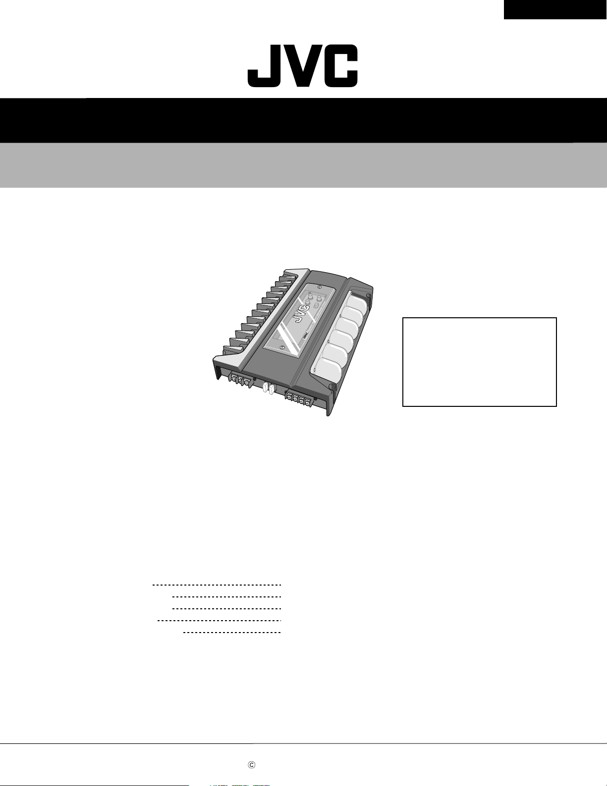
SERVICE MANUAL
POWER AMPLIFIER
KS-AX6700
KS-AX6700KS-AX6700
Caution
If electricity is connected during disassembly, it must be a no load current. If it is load
current, be sure to attach a heat sink to the power-amp IC. This will be damaged if the
above precautions are not followed, as it does not have a sub heat sink attached to it.
Contents
Safety Precaution
Location of main parts
Removal of main parts
Adjustment method
Wire connection diagram
1-2
1-3
1-5
1-8
1-9
Areas suffix
J -------- Nothem America
E ----- Continental Europe
This service manual is printed on 100% recycled paper.
COPYRIGHT 2000 VICTOR COMPANY OF JAPAN, LTD.
No. 49559
Jun. 2000

KS-AX6700
Safety precaution
CAUTION
!
Burrs formed during molding may be left over on some parts of the chassis. Therefore,
pay attention to such burrs in the case of preforming repair of this system.
1-2
KS-AX6700
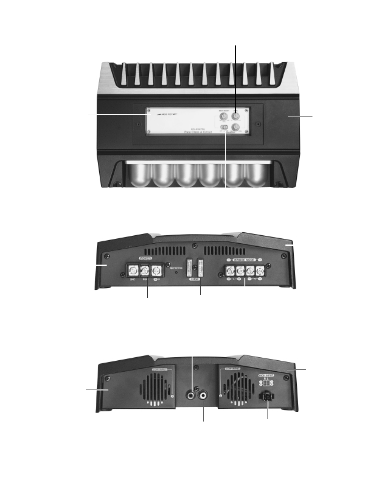
Location of main parts
Control panel
Volume knob
Heat sink
Switch knob
Rear panel
Front panel
Input for power
Fuse
Low input(R)
Heat sink
Output terminal
Heat sink
Low input(L)
High input connector
1-3
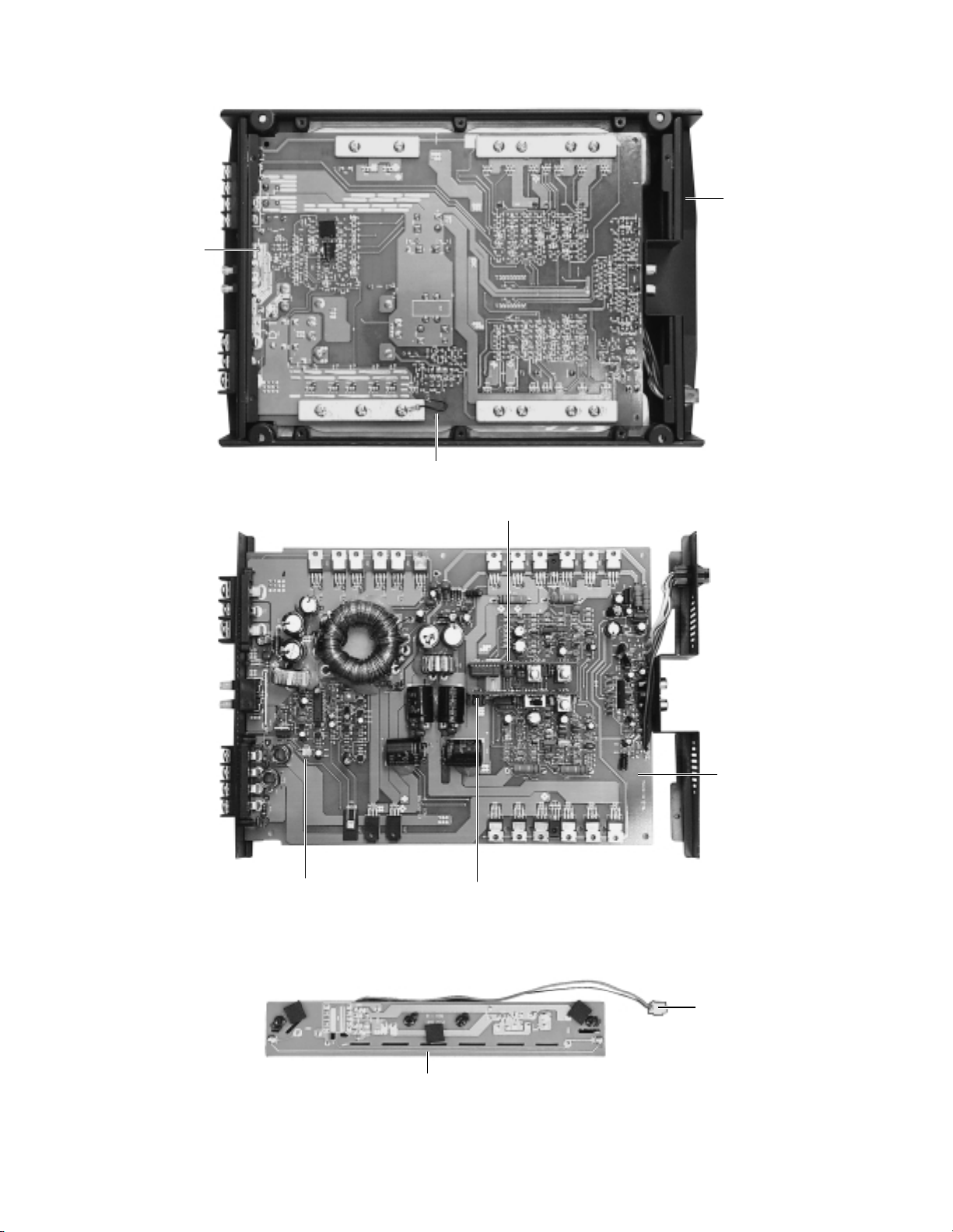
KS-AX6700
Main P.C. board
Heat sink
(Bottom view)
GND wire
2pin connector
(to CCFL P.C. board)
Sub1 P.C. board
Main P.C. board
Sub2 P.C. board
1-4
Wire assemb'y
(from Main)
CCFL P.C. board
Removal of main parts
KS-AX6700
CAUTION:
If electricity is connected during
disassembly, it must be a no load current. If
it is load current, be sure to attach a heat
sink to the power-amp IC. This will be
damaged if the above precautions are not
followed, as it does not have a sub heat
sink attached to it.
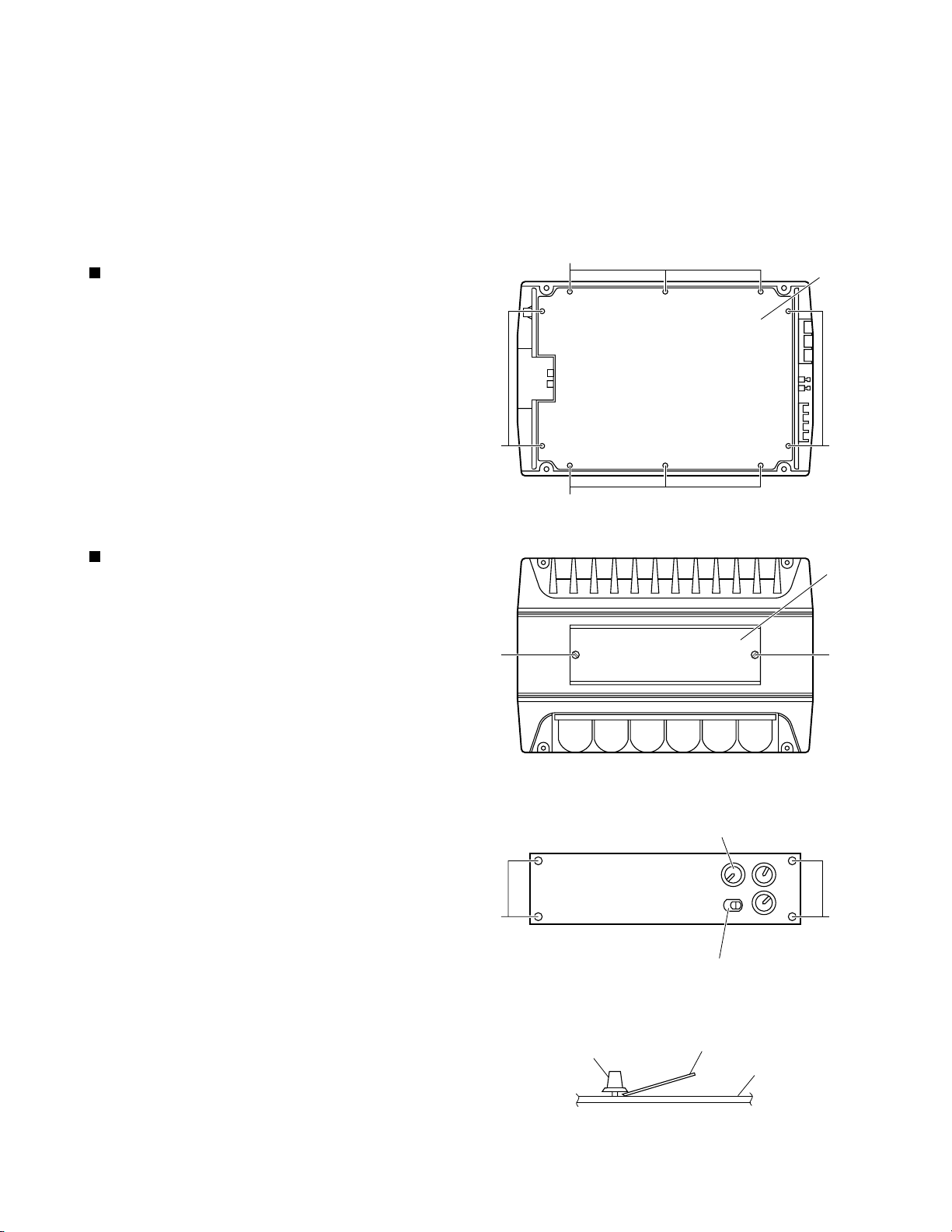
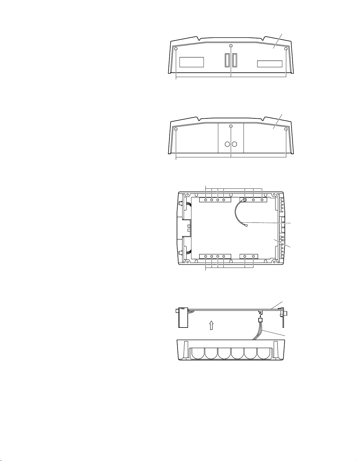
Removing the bottom cover (see Fig. 1)
1.
From the bottom side of the main unit, remove the 4
screws A retaining the bottom cover.
2.
Then remove the 6 screws B retaining the bottom
cover.
3.
Remove the bottom cover.
Removing the main P.C. board
(see Fig. 2 to 8)
1.
Remove the bottom cover from the main unit.
A
B
B
Bottom cover
A
Fig. 1
Top plate
2.
Loosen and remove the 2 screws C retaining the top
plate on the main unit. (Stoppers are attached to the
backs of the C screws so that they cannot be
removed easily.)
3.
Remove the 3 volume knobs on top of the control
panel. If it cannot be pulled out easily, insert a scale
or suitable lever between the base of the volume
knob and the control panel so that the volume knob is
raised a little above the surface and then remove it.
(Be careful when inserting a lever etc. not to
scratch the surface of the control panel).
4.
Remove the 4 screws D retaining the control panel.
Then detach the control panel and the switch knob.
C
D
Volume knob
C
Fig. 2
Volume knob
D
Switch knob
Fig. 3
Scale or suitable lever
Control panel
(Side view)
Fig. 4
1-5
KS-AX6700
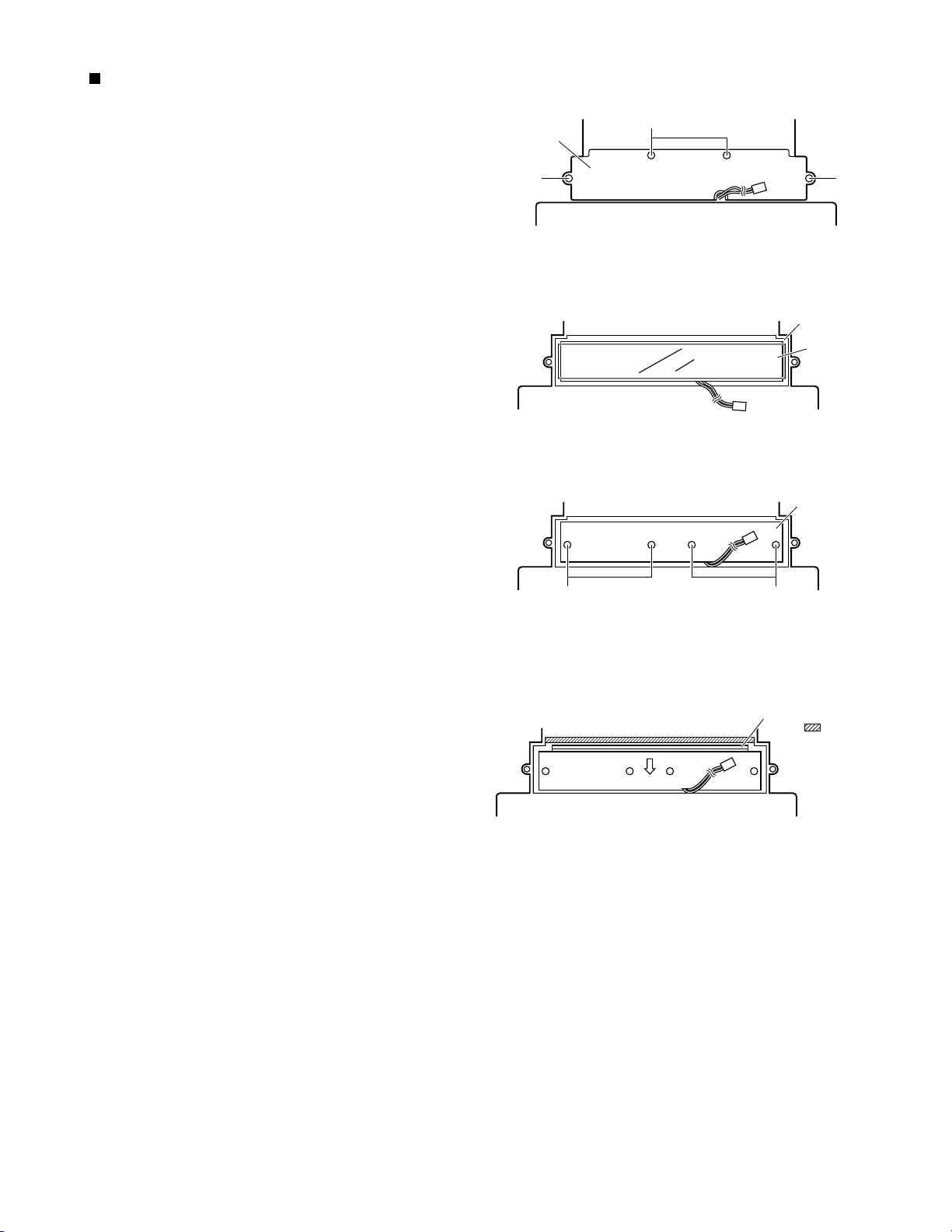
5.
Remove the 6 screws E retaining the panels on both
sides of the main unit.
Rear panel
6.
Remove the 13 screws F attaching the main P.C.
board to the bottom of the main unit.
(The GND wire that protrudes from the main
P.C.board must be re-installed to its original
position during re-assembly.)
E
Fig. 5
Front panel
E
Fig. 6
F
GND wire
Main P.C. board
7.
To remove the wire ass'y, lift up the main P.C. board
a little.
F
Fig. 7
Main P.C. board
Wire assemb'y
(Side view)
Fig. 8
1-6
Removing the CCFL board
(see Fig. 9 to 12)
1.
Remove the bottom cover.
2.
Then remove the Main P.C. board.
3.
From the bottom side of the main unit, remove the 4
screws G retaining the CCFL cover.
4.
Then remove the insulation sheet on top of the CCFL
P.C. board.
KS-AX6700
G
CCFL cover
G G
Fig. 9
CCFL P.C. board
Insulation sheet
Fig. 10
5.
Remove the 4 screws H retaining the CCFL P.C.
board.
6.
Remove the CCFL P.C. board by sliding it a little
towards the arrow mark.
H
CCFL P.C. board
H
Fig. 11
This section is cought
by the portion.
Fig. 12
1-7
KS-AX6700
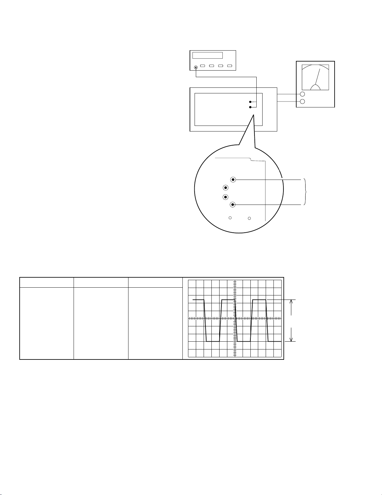
Adjustment method
Check the voltage and frequency of the secondary
1.
toroidal coil.
.
Measure the secondary toroidal coil, if the standard
2.
frequency value of 24.35 kHz ± 10 Hz is not attained,
measure the R760 terminal, then adjust the VR701
so that the R760 terminal becomes 24.25 kHz ± 10Hz.
FREQUENCY:24.35kHz ±10Hz
VOLTAGE VALUE:55Vp-p
FREQUENCY COUNTER
TEST SET
MAIN PCB
R760
(+)
(
POWER SUPPLY
14.4V
-
)
Measuring
Points
Note:
When measuring, adjust and apply power
with no signal or load on each board.
DC/DC CONVERTER SECOND GENERATOR SWITCHING
TEST ITEM
VOLTAGE TEST
FREQUENCY CHECK
SPECIFICATION CONDITION
88Vp-p±2.5V
24.350KHz±10Hz
OSCILLOSCOPE
VOLT/DIV: 10
TIME/DIV: 10mcec
VARIABLE: MINIMUM
88Vp-p
±2.5V
1-8
 Loading...