

Page 1
SERVICE MANUAL
POWER AMPLIFIER
MA17220053
KS-AX3500
Area suffix
J ------------- Northern America
E ------------- Southern Europe
U -------------------- Other Areas
TABLE OF CONTENTS
1 PRECAUTION. . . . . . . . . . . . . . . . . . . . . . . . . . . . . . . . . . . . . . . . . . . . . . . . . . . . . . . . . . . . . . . . . . . . . . . . . 1-3
2 SPECIFIC SERVICE INSTRUCTIONS . . . . . . . . . . . . . . . . . . . . . . . . . . . . . . . . . . . . . . . . . . . . . . . . . . . . . . 1-4
3 DISASSEMBLY . . . . . . . . . . . . . . . . . . . . . . . . . . . . . . . . . . . . . . . . . . . . . . . . . . . . . . . . . . . . . . . . . . . . . . . 1-5
4 ADJUSTMENT . . . . . . . . . . . . . . . . . . . . . . . . . . . . . . . . . . . . . . . . . . . . . . . . . . . . . . . . . . . . . . . . . . . . . . . . 1-6
5 TROUBLESHOOTING . . . . . . . . . . . . . . . . . . . . . . . . . . . . . . . . . . . . . . . . . . . . . . . . . . . . . . . . . . . . . . . . . . 1-7
COPYRIGHT © 2005 Victor Company of Japan, Limited
No.MA172
2005/3
Page 2
SPECIFICATION
Power Output 55 W RMS × 4 channels at 4 Ω and [ < or = ] 1% THD + N
Signal-to-Noise Ratio 86 dBA (reference: 1 W into 4 Ω)
Maximum Power Output 580 W
Load Impedance 4 Ω (2 Ω to 8 Ω allowance)
4 Ω (4 Ω to 8 Ω allowance) (Bridge mode)
Frequency Response 5 Hz to 50,000 Hz ( +0, -3 dB)
Input Sensitivity/Impedance 1 V/20 kΩ (0.3 V to 6 V, variable)
Distortion Less than 0.005% (at 1 kHz)
Power Requirement DC 14.4 V (11 V to 16 V allowance)
Grounding system Negative ground
Dimensions (W/H/D) 347 mm × 54 mm × 222 mm (13-11/16 in. × 2-3/16 in. × 8-3/4 in.)
Mass (approx.) 2.8 kg (6.2 lbs.)
Design and specifi cations are subject to change without notice.
1-2 (No.MA172)
Page 3

1.1 Safety Precautions
SECTION 1
PRECAUTION
!
Burrs formed during molding may be left over on some parts of the chassis. Therefore,
pay attention to such burrs in the case of preforming repair of this system.
(No.MA172)1-3
Page 4

SECTION 2
SPECIFIC SERVICE INSTRUCTIONS
This service manual does not describe SPECIFIC SERVICE INSTRUCTIONS.
1-4 (No.MA172)
Page 5
SECTION 3
A
A
DISASSEMBLY
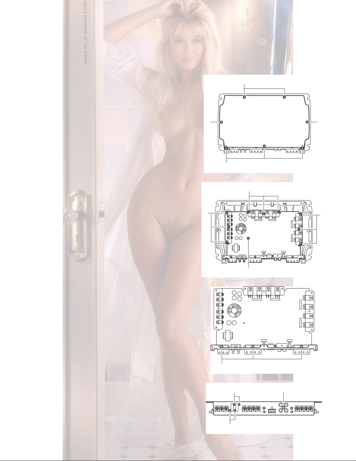
3.1 Main board
3.1.1 Removing the main board
(See Fig.1 to 4)
(1) From the bottom of the amplifier, remove the seven screws
A attaching the cover.
(2) From the main body of the amplifier, remove the nine
screws B and the screw C attaching the main board.
(3) Remove the three screws D on top of the rear cover.
(4) Remove the screw E and the four screws F on the front
side of the rear cover.
A
A
Fig.1
B
B
B
C
Fig.2
D
Fig.3
EF
F
Fig.4
(No.MA172)1-5
Page 6

SECTION 4
ADJUSTMENT
This service manual does not describe ADJUSTMENT.
1-6 (No.MA172)
Page 7

SECTION 5
TROUBLESHOOTING
This service manual does not describe TROUBLESHOOTING.
(No.MA172)1-7
Page 8

Victor Company of Japan, Limited
AV & MULTIMEDIA COMPANY CAR ELECTRONICS CATEGORY 10-1,1chome,Ohwatari-machi,Maebashi-city,371-8543,Japan
(No.MA172)
Printed in Japan
VPT
Page 9

KS-AX3500
KS-AX3300
POWER AMPLIFIER: INSTRUCTIONS
AMPLIFICATEUR DE PUISSANCE: MANUEL D’INSTRUCTIONS
LVT1329-001A
[J/E/U]
1204MNMMDWASH
EN, FR
© 2004 Victor Company of Japan, Limited
ENGLISH
KS-AX3500
Thank you for purchasing a JVC product. Please read all instructions carefully before operation, to ensure
your complete understanding and to obtain the best possible performance from the unit.
For safety....
•
Do not raise the volume level too much, as this will block outside sounds, making driving dangerous.
• Stop the car before performing any complicated operations.
CAUTIONS AND NOTES
This unit is designed to operate on 12 V DC, NEGATIVE ground electrical systems.
• This unit uses BTL (Balanced Trans-formerless) amplifi er circuitry, i.e., fl oating ground system,
so please comply with the following:
∗ Do not connect the “·” terminals of the speakers to each other.
∗ Do not connect the “·” terminals of the speakers to the metal body or chassis.
• Cover the unused terminals with insulating tape to prevent them from short circuiting.
•
When an extension lead is used, it should be as thick and short as possible; connect it fi rmly
with insulating tape.
• Be sure to leave an appropriate space between the antenna (aerial) and the wires of this unit.
•
When replacing the fuse, only use a 25 A fuse for KS-AX3500 and 30 A fuse for KS-AX3300.
• Do not let pebbles, sand or metallic objects get inside the unit.
•
To keep the heat dissipation mechanism running effectively, wipe the accumulated dust off periodically.
• Listening to the tape, radio, CD or MD, etc. with the volume on loud for a long period of time will
exhaust the battery, while the engine is turned off or while the engine is idling.
DO NOT disassemble the units since there are no user serviceable parts inside.
For Customer Use:
Enter below the Model No. and Serial No. which
are located on the top or bottom of the cabinet.
Retain this information for future reference.
KS-AX3300
Model No.
Serial No.
POWER SUPPLY
CAUTION
To prevent short circuits while making connections, keep the battery’s negative terminal
disconnected.
• When using a power cord, be sure to place the 30 A fuse near the battery as shown.
• Connect the lead wire (purchased separately) through which power is supplied directly to the
battery’s “ª” terminal only after all the other connections have been made.
The lead wire connected to the + B terminal of this unit should have a cross-section of more
than 5 mm
• If you have any questions regarding the thickness of the power cord, etc., consult your nearest
“JVC IN-CAR ENTERTAINMENT” car audio dealer.
When connecting a unit without a remote lead (.), connect to the accessory circuit of the car
which is activated by the ignition switch. In this case, noise may occur when the car receiver is
turned on or off. To avoid this noise, do not turn on or off the car receiver itself. You can turn on or
off the car receiver along with the on/off operation of the ignition switch.
If you use JVC car receiver with a remote lead (∫), connect to the REM terminal on this unit.
If the POWER/PROTECTOR lamp lights in red, it indicates incorrect speaker wiring or
connections. In normal status, the POWER/PROTECTOR lamp lights in green. Make sure to
correct speaker wiring and other connections.
2
. Be sure to use a ring terminal (optional) for secure connection.
INSTALLATION
The following illustration shows a typical installation. However, you should make adjustments
corresponding to your specifi c car. If you have any questions or require information regarding
installation kits, consult your “JVC IN-CAR ENTERTAINMENT” car audio dealer or a company
supplying kits.
Å Mount on a fi rm surface, such as in the trunk room or under the front seat.
• Since heat is generated in this unit, do not mount near infl ammable objects. In addition,
mount in an area that will not prevent the unit from dissipating heat.
• Do not mount the unit in the places subject to heat such as near a radiator, in a glove
compartment or in insulated areas such as under a car mat that will prevent the unit from
dissipating heat.
ı When mounting this unit, be sure to use the screws provided. If any other screws are used,
there is a risk of loosening the unit or damaging parts inside it.
TERMINAL CONNECTIONS
CONTROLS
KS-AX3500
Å Crossover fi lter switch
OFF: Normally, set to this position. (Preset to this position at the factory.)
ON: (For LPF switch) Set to this position when you want to turn on the LPF (Low-pass
fi lter) switch. You can use the following terminals for a subwoofer
system.
KS-AX3500: REAR SPEAKER OUTPUT
KS-AX3300: SPEAKER OUTPUT
(For HPF switch—only for KS-AX3500)
Set to this position when you want to turn on the HPF (High-pass
fi lter) switch. The low frequency signals are not applied to the left/
right speaker when a subwoofer is connected.
ı Input LEVEL controller
The input level can be adjusted with this control when this unit is connected to other source
equipments. Turn it in the clockwise direction when the output level of the car audio seems low.
KS-AX3300
When making the terminal connections…
Properly fi x the terminal with the screw provided by turning it in the
direction as illustrated.
Note
When you tighten the screw, make sure that the screw is securely fi xed in
place to prevent disconnection of the terminal. Avoid over-tightening as it
may cause damage to the screw or its head slot.
SPEAKER SYSTEMS
This amplifi er provides two types of speaker connections: Normal mode and Bridge mode. You
can choose either type of connections depending on the speakers confi guration equipped on
your car.
Make sure to comply with the following notes:
• Be sure not to connect the “·” terminals of the speakers to a common point.
• If the ground wire is common to both left/right and front/rear speaker wirings, this unit cannot be
used. Always use the independent lead wires for the speakers to be used. In this case, redo the
wirings.
• Use the speakers with an impedance of 2 Ω to 8 Ω (4 Ω to 8 Ω: when used in Bridge mode).
• Use the speakers which have suffi cient power to the unit.
1
Page 10

LR
L
R
LR
LR
L
R
LR
SPEAKER CONNECTIONS
Connection varies depending on the number of the speakers used in your car. Select the
appropiate connection referring to the diagrams below.
Before connecting: Securely connect all the parts. If the connections are loose, due to contact
resistance etc., heat will break out and may cause an accident. Secure and cover the cords with
insulating tape and run them under the car mats.
• Depending on the manufacturer and model of the car, speaker wiring may have been fi nished
when purchased. If the ground wire is common to both left and right speakers, this unit cannot
be used. In this case, redo the speaker wiring.
å When your receiver is equipped with Line Output, connect the Line Output (through the
receiver) to the LOW INPUT jacks on this unit.
∫ When your receiver is NOT equipped with Line Output, connect the speaker connector
(through the receiver) to the HIGH INPUT terminal on this unit.
KS-AX3500
4-speaker system
2-speaker system plus subwoofer—BRIDGE MODE
KS-AX3300
2-speaker system
Subwoofer system—BRIDGE MODE*
2
*
2
2-speaker system—BRIDGE MODE
1-speaker system—BRIDGE MODE*
2
*
1
Not supplied for this unit.
*
2
2
BRIDGE MODE: Be sure to connect the line output
*
from the receiver to the left (L) jack on this unit.
TROUBLESHOOTING
For more details, consult your “JVC IN-CAR ENTERTAINMENT” car audio dealer.
The POWER/PROTECTOR lamp does not light.
• Confi rm if the fuse is blown.
• Confi rm if the ground lead is connected securely to a metal part of the car.
• Make sure that the equipment connected to this unit is turned on.
• Use a relay if your system employs too many amplifi ers.
• Confi rm the battery voltage (11 V to 16 V).
The POWER/PROTECTOR lamp lights in red and/or the unit heats up abnormally.
• Confi rm if the impedance of the connected speaker is suitable.
• Confi rm if the speaker wirings are short-circuited.
• Leave the unit turned off for a while as it cools down.
No sound is heard.
• Confi rm if the POWER/PROTECTOR lamp lights in green (see “POWER SUPPLY” on page 1).
• Is the remote turn-on line lead connected correctly?
• Are RCA pin cords connected to the LOW INPUT jacks?
• Is the speaker input connector from the receiver connected to the HIGH INPUT terminal?
• Is this amplifi er grounded?
Alternator noise is heard.
• Keep the power connecting leads away from the RCA pin cords.
• Keep the RCA pin cords away from other electrical cables in the car.
• Confi rm if the ground lead is connected securely to a metal part of the car.
• Confi rm if the negative speaker leads are touching the car chassis.
• Confi rm if the noise originates in the receiver.
• Replace the plugs or use plugs with load resistors.
• Connect a bypass capacitor across the accessory switches (horn, fan, etc.).
Noise when connected to AM (MW/LW) tuner.
• Move the speaker and power leads away from the antenna (aerial) lead.
SPECIFICATIONS
Power Output KS-AX3500: 55 W RMS × 4 channels at 4 Ω and ≤ 1% THD + N
KS-AX3300: 65 W RMS × 2 channels at 4 Ω and ≤ 1% THD + N
Signal-to-Noise Ratio 86 dBA (reference: 1 W into 4 Ω)
Maximum Power Output KS-AX3500: 580 W
KS-AX3300: 320 W
Load Impedance 4 Ω (2 Ω to 8 Ω allowance)
4 Ω (4 Ω to 8 Ω allowance) (Bridge mode)
Frequency Response 5 Hz to 50,000 Hz ( +0, –3 dB)
Input Sensitivity/Impedance 1 V/20 kΩ (0.3 V to 6 V, variable)
Distortion Less than 0.005% (at 1 kHz)
Power Requirement DC 14.4 V (11 V to 16 V allowance)
Grounding system Negative ground
Dimensions (W/H/D) KS-AX3500: 347 mm × 54 mm × 222 mm
KS-AX3300: 259 mm × 54 mm × 172 mm
Mass (approx.) KS-AX3500: 2.8 kg (6.2 lbs.)
KS-AX3300: 1.6 kg (3.6 lbs.)
Supplied Accessories Speaker input connector × 1
Mounting Screw (φ 4.0 × 20 mm (
Design and specifi cations are subject to change without notice.
2
(13
-11/16 in. × 2
(10
-1/4 in. × 2
-3/16 in. × 8
-3/16 in. × 6
-3/4 in.)
-13/16 in.)
13
/16 in.)
) × 4
Page 11

SCHEMATIC DIAGRAMS
POWER AMPLIFIER
KS-AX3500
CD-ROM No.SML200503
Area suffix
J ---------- Northern America
E ---------- Southern Europe
U ----------------- Other Areas
Contents
Block diagram
Standard schematic diagram
Printed circuit board
COPYRIGHT 2005 Victor Company of Japan, Limited.
2-1
2-2
2-3
No.MA172SCH
2005/3
Page 12

Safety precaution
!
Burrs formed during molding may be left over on some parts of the chassis. Therefore,
pay attention to such burrs in the case of preforming repair of this system.
Page 13

Block diagram
T
T
HIGH
CN901
INPUT
FRONT
L+,L-
R+,R-
REAR
L+,L-
R+,R-
IC801
IC803
SW801
HPF ON/OFF
LEVEL
VR
801
IC805
FRONT
OUTPU
LOW
INPUT
CN902
REAR
L+,L-
R+,R-
FRONT
L+,L-
R+,R-
F901
25A
IC802
SW802
LPF ON/OFF
LEVEL
VR
IC804 IC806
802
CN903
REAR
OUTPU
BATT
REMOTE
GND
CN904
F902
25A
T901
LED901
IC901
2-1
Page 14

Standard schematic diagram
2-2
Page 15

Printed circuit board
Main board
2-3
Page 16

Victor Company of Japan, Limited
AV & MULTIMEDIA COMPANY CAR ELECTRONICS CATEGORY 10-1,1chome,Ohwatari-machi,Maebashi-city,371-8543,Japan
(No.MA172SCH)
Printed in Japan
VPT
Page 17

PARTS LIST
[ KS-AX3500 ]
* All printed circuit boards and its assemblies are not available as service parts.
Area suffix
J ------------- Northern America
E ------------- Southern Europe
U
-------------------- Other Areas
MA172
- Contents -
Exploded view of general assembly and parts list (Block No.M1)
Electrical parts list (Block No.01)
Packing materials and accessories parts list (Block No.M3)
3-2
3-4
3-8
3-1
Page 18

Exploded view of general assembly and parts list
12
Block No.
M
M
1
M
11
10
8
8
5
8
10
8
10
8
10
8
8
9
8
9
2
2
8
10
9
10
8
8
8
8
8
10
10
8
8
9
7
7
2
F902
13
F901
7
9
8
8
8
8
3
Amp
board
11
11
8
6
4
9
11
1
3-2
Page 19

General Assembly
Symbol No. Part No. Part Name Description Local
1 A4265360-001-0 HEAT SINK
2 A1265345-001-0 HEAT SINK SUB (x3)
3 A1256475-001-0 BUS BAR
4 A3146067-001-A FRONT CHASSIS
5 A2146068-001-0 BOTTOM COVER
6 A3247033-002-B PLATE
7 A3292008-004-2 SCREW 2x8(x4)
8 A3293008-032-2 SCREW 3x8(x21)
9 A2285199-003-0 SCREW 3x8(x6)
10 A2285195-002-0 SCREW 3x8.5(x14)
11 A3293008-002-7 SCREW 3x8(x6)
12 A1236248-003-0 RATING LABEL E
12 A1236248-001-0 RATING LABEL J
12 A1236248-002-0 RATING LABEL U
13 A151-5190-025 FUSE 25A F901 F902(x2)
Block No. [M][1][M][M]
3-3
Page 20

Electrical parts list
AMP board
Block No. [0][1]
Symbol No.
IC801 NJM4565M IC AC08-086-002 TE1
IC802 NJM4565M IC AC08-086-002 TE1
IC803 NJM4565M IC AC08-086-002 TE1
IC804 NJM4565M IC AC08-086-002 TE1
IC805 NJM4565M IC AC08-086-002 TE1
IC806 NJM4565M IC AC08-086-002 TE1
IC901 UPC494GS-E1-A IC AC08-004-002
IC902 PS2501-1 IC A149-5233-008
Q101 2SC3326 TRANSISTOR
Q102 2SA1618 TRANSISTOR
Q103 2SC4207 TRANSISTOR
Q104 2SA988F TRANSISTOR AT04-095-005
Q105 2SC1841F TRANSISTOR AT04-094-005
Q106 2SD637 TRANSISTOR A148-5484-002
Q107 2SA1037AK TRANSISTOR
Q108 2SC2235 TRANSISTOR
Q109 2SA965 TRANSISTOR
Q110 2SC5100 TRANSISTOR
Q111 2SA1908 TRANSISTOR
Q112 DTC114EKA TRANSISTOR
Q201 2SC3326 TRANSISTOR
Q202 2SA1618 TRANSISTOR
Q203 2SC4207 TRANSISTOR
Q204 2SA988F TRANSISTOR AT04-095-005
Q205 2SC1841F TRANSISTOR AT04-094-005
Q206 2SD637 TRANSISTOR A148-5484-002
Q207 2SA1037AK TRANSISTOR
Q208 2SC2235 TRANSISTOR
Q209 2SA965 TRANSISTOR
Q210 2SC5100 TRANSISTOR
Q211 2SA1908 TRANSISTOR
Q212 DTC114EKA TRANSISTOR
Q301 2SC3326 TRANSISTOR
Q302 2SA1618 TRANSISTOR
Q303 2SC4207 TRANSISTOR
Q304 2SA988F TRANSISTOR AT04-095-005
Q305 2SC1841F TRANSISTOR AT04-094-005
Q306 2SD637 TRANSISTOR A148-5484-002
Q307 2SA1037AK TRANSISTOR
Q308 2SC2235 TRANSISTOR
Q309 2SA965 TRANSISTOR
Q310 2SC5100 TRANSISTOR
Q311 2SA1908 TRANSISTOR
Q312 DTC114EKA TRANSISTOR
Q401 2SC3326 TRANSISTOR
Part No. Part Name Description Local
AC04-083-003
TE85R F
AC04-178-003
TE85L F
AC04-177-004
TE85L F
AC04-051-005
T146
AT04-219-004
TPE6 F
AT04-220-004
TPE6 F
A148-5363-005
LF719
A148-5364-005
LF719
AC04-311-003
T146
AC04-083-003
TE85R F
AC04-178-003
TE85L F
AC04-177-004
TE85L F
AC04-051-005
T146
AT04-219-004
TPE6 F
AT04-220-004
TPE6 F
A148-5363-005
LF719
A148-5364-005
LF719
AC04-311-003
T146
AC04-083-003
TE85R F
AC04-178-003
TE85L F
AC04-177-004
TE85L F
AC04-051-005
T146
AT04-219-004
TPE6 F
AT04-220-004
TPE6 F
A148-5363-005
LF719
A148-5364-005
LF719
AC04-311-003
T146
AC04-083-003
TE85R F
Symbol No.
Q402 2SA1618 TRANSISTOR
Q403 2SC4207 TRANSISTOR
Q404 2SA988F TRANSISTOR AT04-095-005
Q405 2SC1841F TRANSISTOR AT04-094-005
Q406 2SD637 TRANSISTOR A148-5484-002
Q407 2SA1037AK TRANSISTOR
Q408 2SC2235 TRANSISTOR
Q409 2SA965 TRANSISTOR
Q410 2SC5100 TRANSISTOR
Q411 2SA1908 TRANSISTOR
Q412 DTC114EKA TRANSISTOR
Q801 DTA114EKA TRANSISTOR
Q802 2SC2412K TRANSISTOR
Q803 2SC2412K TRANSISTOR
Q804 2SC2412K TRANSISTOR
Q805 2SC2412K TRANSISTOR
Q806 2SC2412K TRANSISTOR
Q807 2SD2012F TRANSISTOR A148-5290-002
Q808 2SB1375F TRANSISTOR A148-5291-002
Q809 DTA114EKA TRANSISTOR
Q810 DTA114EKA TRANSISTOR
Q811 DTA114EKA TRANSISTOR
Q901 DTC114EKA TRANSISTOR
Q902 DTA144EKA TRANSISTOR
Q903 DTC114EKA TRANSISTOR
Q904 DTC114EKA TRANSISTOR
Q905 2SB1132 TRANSISTOR
Q906 2SC2412K TRANSISTOR
Q907 DTC114EKA TRANSISTOR
Q908 2SC3326 TRANSISTOR
Q909 2SC3326 TRANSISTOR
Q910 FKV550N FET A148-5560-001
Q911 FKV550N FET A148-5560-001
Q912 FKV550N FET A148-5560-001
Q913 FKV550N FET A148-5560-001
D101 DAN202K DIODE ARRAY
D102 DAN202K DIODE ARRAY
D201 DAN202K DIODE ARRAY
D202 DAN202K DIODE ARRAY
D301 DAN202K DIODE ARRAY
D302 DAN202K DIODE ARRAY
D401 DAN202K DIODE ARRAY
D402 DAN202K DIODE ARRAY
D801 UDZS6.8B Z DIODE
Part No. Part Name Description Local
AC04-178-003
TE85L F
AC04-177-004
TE85L F
AC04-051-005
T146
AT04-219-004
TPE6 F
AT04-220-004
TPE6 F
A148-5363-005
LF719
A148-5364-005
LF719
AC04-311-003
T146
AC04-310-003
T146
AC04-050-005
T146
AC04-050-005
T146
AC04-050-005
T146
AC04-050-005
T146
AC04-050-005
T146
AC04-310-003
T146
AC04-310-003
T146
AC04-310-003
T146
AC04-311-003
T146
AC04-310-005
T146
AC04-311-003
T146
AC04-311-003
T146
AC04-044-003
T100
AC04-050-005
T146
AC04-311-003
T146
AC04-083-003
TE85R F
AC04-083-003
TE85R F
AC04-053-002
T146
AC04-053-002
T146
AC04-053-002
T146
AC04-053-002
T146
AC04-053-002
T146
AC04-053-002
T146
AC04-053-002
T146
AC04-053-002
T146
AC04-312-068
TE17
3-4
Page 21

Symbol No.
Part No. Part Name Description Local
Symbol No.
Part No. Part Name Description Local
D802 DAN202K DIODE ARRAY
D803 FCH20A15 DIODE ARRAY A148-5522-002
D804 FCH20A15 DIODE ARRAY A148-5523-002
D805 UDZS13B Z DIODE
D806 UDZS15B Z DIODE
D807 DAN202K DIODE ARRAY
D901 DAN202K DIODE ARRAY
D902 DAN202K DIODE ARRAY
D903 DAN202K DIODE ARRAY
D904 UDZS16B Z DIODE
C101 AC03-430-101 C CAPACITOR 100pF 50V
C102 AC03-430-101 C CAPACITOR 100pF 50V
C105 AC03-430-470 C CAPACITOR 47pF 50V
C106 AC03-430-101 C CAPACITOR 100pF 50V
C107 AC03-430-101 C CAPACITOR 100pF 50V
C108 AC03-432-104 C CAPACITOR 0.1uF 25V
C109 AC03-432-104 C CAPACITOR 0.1uF 25V
C110 AT03-B77-107 E CAPACITOR 100uF 16V
C111 AT03-B80-475 E CAPACITOR 4.7uF 50V
C112 AC03-430-101 C CAPACITOR 100pF 50V
C151 AT03-B77-476 E CAPACITOR 47uF 16V
C152 AC03-430-470 C CAPACITOR 47pF 50V
C153 AC03-430-220 C CAPACITOR 22pF 50V
C154 AC03-432-104 C CAPACITOR 0.1uF 25V
C155 AC03-432-104 C CAPACITOR 0.1uF 25V
C156 AC03-432-104 C CAPACITOR 0.1uF 25V
C201 AC03-430-101 C CAPACITOR 100pF 50V
C202 AC03-430-101 C CAPACITOR 100pF 50V
C205 AC03-430-470 C CAPACITOR 47pF 50V
C206 AC03-430-101 C CAPACITOR 100pF 50V
C207 AC03-430-101 C CAPACITOR 100pF 50V
C208 AC03-432-104 C CAPACITOR 0.1uF 25V
C209 AC03-432-104 C CAPACITOR 0.1uF 25V
C210 AT03-B77-107 E CAPACITOR 100uF 16V
C211 AT03-B80-475 E CAPACITOR 4.7uF 50V
C212 AC03-430-101 C CAPACITOR 100pF 50V
C251 AT03-B77-476 E CAPACITOR 47uF 16V
C252 AC03-430-470 C CAPACITOR 47pF 50V
C253 AC03-430-220 C CAPACITOR 22pF 50V
C254 AC03-432-104 C CAPACITOR 0.1uF 25V
C255 AC03-432-104 C CAPACITOR 0.1uF 25V
C256 AC03-432-104 C CAPACITOR 0.1uF 25V
C301 AC03-430-101 C CAPACITOR 100pF 50V
C302 AC03-430-101 C CAPACITOR 100pF 50V
C305 AC03-430-470 C CAPACITOR 47pF 50V
C306 AC03-430-101 C CAPACITOR 100pF 50V
C307 AC03-430-101 C CAPACITOR 100pF 50V
C308 AT03-B80-105 E CAPACITOR 1uF 50V
C309 AC03-428-474 C CAPACITOR 0.47uF 10V
C310 AC03-432-104 C CAPACITOR 0.1uF 25V
C311 AT03-B77-107 E CAPACITOR 100uF 16V
C312 AC03-430-101 C CAPACITOR 100pF 50V
C351 AT03-B77-476 E CAPACITOR 47uF 16V
C352 AC03-430-470 C CAPACITOR 47pF 50V
C353 AC03-430-220 C CAPACITOR 22pF 50V
C354 AC03-432-104 C CAPACITOR 0.1uF 25V
C355 AC03-432-104 C CAPACITOR 0.1uF 25V
C356 AC03-432-104 C CAPACITOR 0.1uF 25V
C401 AC03-430-101 C CAPACITOR 100pF 50V
C402 AC03-430-101 C CAPACITOR 100pF 50V
C405 AC03-430-470 C CAPACITOR 47pF 50V
C406 AC03-430-101 C CAPACITOR 100pF 50V
C407 AC03-430-101 C CAPACITOR 100pF 50V
C408 AT03-B80-105 E CAPACITOR 1uF 50V
C409 AC03-428-474 C CAPACITOR 0.47uF 10V
C410 AC03-432-104 C CAPACITOR 0.1uF 25V
C411 AT03-B77-107 E CAPACITOR 100uF 16V
C412 AC03-430-101 C CAPACITOR 100pF 50V
C451 AT03-B77-476 E CAPACITOR 47uF 16V
C452 AC03-430-470 C CAPACITOR 47pF 50V
AC04-053-002
T146
AC04-312-130
TE17
AC04-312-150
TE17
AC04-053-002
T146
AC04-053-002
T146
AC04-053-002
T146
AC04-053-002
T146
AC04-312-160
TE17
C453 AC03-430-220 C CAPACITOR 22pF 50V
C454 AC03-432-104 C CAPACITOR 0.1uF 25V
C455 AC03-432-104 C CAPACITOR 0.1uF 25V
C456 AC03-432-104 C CAPACITOR 0.1uF 25V
C801 AC03-433-224 C CAPACITOR 0.22uF 16V
C802 AT03-B77-227 E CAPACITOR 220uF 16V
C803 AC03-433-224 C CAPACITOR 0.22uF 16V
C804 AC03-433-224 C CAPACITOR 0.22uF 16V
C805 AC03-432-104 C CAPACITOR 0.1uF 25V
C808 AC03-432-104 C CAPACITOR 0.1uF 25V
C809 AC03-432-104 C CAPACITOR 0.1uF 25V
C810 AT03-B80-226 E CAPACITOR 22uF 50V
C811 AC03-431-102 C CAPACITOR 1000pF 50V
C812 AC03-431-102 C CAPACITOR 1000pF 50V
C813 AT03-B75-477 E CAPACITOR 470uF 6.3V
C814 AT03-B75-477 E CAPACITOR 470uF 6.3V
C815 AT03-B77-107 E CAPACITOR 100uF 16V
C817 AC03-431-103 C CAPACITOR 0.01uF 50V
C818 AC03-431-103 C CAPACITOR 0.01uF 50V
C819 A116-6405-158 E CAPACITOR 1500uF 35V
C820 A116-6405-158 E CAPACITOR 1500uF 35V
C821 A116-6405-158 E CAPACITOR 1500uF 35V
C822 A116-6405-158 E CAPACITOR 1500uF 35V
C823 AC03-431-102 C CAPACITOR 1000pF 50V
C824 AC03-432-104 C CAPACITOR 0.1uF 25V
C825 AC03-432-104 C CAPACITOR 0.1uF 25V
C826 AT03-B77-107 E CAPACITOR 100uF 16V
C827 AT03-B77-107 E CAPACITOR 100uF 16V
C901 AC03-429-105 C CAPACITOR 1uF 10V
C902 AC03-431-102 C CAPACITOR 1000pF 50V
C903 AC03-431-103 C CAPACITOR 0.01uF 50V
C904 AC03-431-103 C CAPACITOR 0.01uF 50V
C905 AC03-431-102 C CAPACITOR 1000pF 50V
C906 AT03-B77-107 E CAPACITOR 100uF 16V
C907 AC03-432-104 C CAPACITOR 0.1uF 25V
C908 AT03-B77-107 E CAPACITOR 100uF 16V
C909 AC03-431-102 C CAPACITOR 1000pF 50V
C910 AT03-B82-474 M CAPACITOR 0.47uF 50V
C911 AC03-432-104 C CAPACITOR 0.1uF 25V
C912 AC03-432-104 C CAPACITOR 0.1uF 25V
C913 A116-6419-228 E CAPACITOR 2200uF 16V
C914 A116-6419-228 E CAPACITOR 2200uF 16V
C915 AC03-431-103 C CAPACITOR 0.01uF 50V
C916 AC03-431-103 C CAPACITOR 0.01uF 50V
C917 AC03-431-103 C CAPACITOR 0.01uF 50V
C918 AC03-432-104 C CAPACITOR 0.1uF 25V
Ω
R101 AC02-083-222 C RESISTOR 2.2K
R102 AC02-081-223 C RESISTOR 22K
R103 AC02-081-223 C RESISTOR 22K
R104 AC02-081-224 C RESISTOR 220K
R105 AC02-081-224 C RESISTOR 220K
R106 AC02-081-153 C RESISTOR 15K
R107 AC02-081-153 C RESISTOR 15K
R108 AC02-081-153 C RESISTOR 15K
R109 AC02-081-303 C RESISTOR 30K
R110 AC02-081-103 C RESISTOR 10K
R111 AC02-081-103 C RESISTOR 10K
R112 AC02-081-681 C RESISTOR 680
R113 AC02-081-682 C RESISTOR 6.8K
R151 AC02-083-103 C RESISTOR 10K
R152 AC02-081-472 C RESISTOR 4.7K
R153 AC02-081-222 C RESISTOR 2.2K
R154 AC02-083-103 C RESISTOR 10K
R155 AC02-081-333 C RESISTOR 33K
R156 AC02-081-333 C RESISTOR 33K
R157 AC02-081-152 C RESISTOR 1.5K
R158 AC02-081-152 C RESISTOR 1.5K
R159 AC02-081-101 C RESISTOR 100
R160 AC02-081-101 C RESISTOR 100
R161 AC02-081-104 C RESISTOR 100K
R162 AC02-081-104 C RESISTOR 100K
R163 AC02-081-681 C RESISTOR 680
R164 AC02-081-221 C RESISTOR 220
R165 AC02-081-103 C RESISTOR 10K
R166 AC02-083-221 C RESISTOR 220
R167 AC02-083-2R2 C RESISTOR 2.2
R168 AC02-083-2R2 C RESISTOR 2.2
Ω
Ω
Ω
Ω
Ω
Ω
Ω
Ω
Ω
Ω
Ω
1/10W
Ω
Ω
Ω
Ω
Ω
Ω
Ω
Ω
Ω
Ω
1/10W
Ω
1/10W
Ω
Ω
Ω
1/10W
Ω
1/10W
Ω
Ω
1/4W
Ω
1/4W
Ω
1/4W
1/4W
1/10W
1/10W
1/10W
1/10W
1/10W
1/10W
1/10W
1/10W
1/10W
1/10W
1/10W
1/4W
1/10W
1/10W
1/4W
1/10W
1/10W
1/10W
1/10W
1/10W
1/10W
1/10W
3-5
Page 22

Symbol No.
Part No. Part Name Description Local
Symbol No.
Part No. Part Name Description Local
R169 A142-5470-R10 RESISTOR
R170 AC02-081-103 C RESISTOR 10K
R171 AC02-081-473 C RESISTOR 47K
R172 AC02-083-2R2 C RESISTOR 2.2
R175 AC02-081-152 C RESISTOR 1.5K
R176 AC02-081-152 C RESISTOR 1.5K
R177 AC02-081-472 C RESISTOR 4.7K
R201 AC02-083-222 C RESISTOR 2.2K
R202 AC02-081-223 C RESISTOR 22K
R203 AC02-081-223 C RESISTOR 22K
R204 AC02-081-224 C RESISTOR 220K
R205 AC02-081-224 C RESISTOR 220K
R206 AC02-081-153 C RESISTOR 15K
R207 AC02-081-153 C RESISTOR 15K
R208 AC02-081-153 C RESISTOR 15K
R209 AC02-081-303 C RESISTOR 30K
R210 AC02-081-103 C RESISTOR 10K
R211 AC02-081-103 C RESISTOR 10K
R212 AC02-081-681 C RESISTOR 680
R213 AC02-081-682 C RESISTOR 6.8K
R251 AC02-083-103 C RESISTOR 10K
R252 AC02-081-472 C RESISTOR 4.7K
R253 AC02-081-222 C RESISTOR 2.2K
R254 AC02-083-103 C RESISTOR 10K
R255 AC02-081-333 C RESISTOR 33K
R256 AC02-081-333 C RESISTOR 33K
R257 AC02-081-152 C RESISTOR 1.5K
R258 AC02-081-152 C RESISTOR 1.5K
R259 AC02-081-101 C RESISTOR 100
R260 AC02-081-101 C RESISTOR 100
R261 AC02-081-104 C RESISTOR 100K
R262 AC02-081-104 C RESISTOR 100K
R263 AC02-081-681 C RESISTOR 680
R264 AC02-081-221 C RESISTOR 220
R265 AC02-081-103 C RESISTOR 10K
R266 AC02-083-221 C RESISTOR 220
R267 AC02-083-2R2 C RESISTOR 2.2
R268 AC02-083-2R2 C RESISTOR 2.2
R269 A142-5470-R10 RESISTOR
R270 AC02-081-103 C RESISTOR 10K
R271 AC02-081-473 C RESISTOR 47K
R272 AC02-083-2R2 C RESISTOR 2.2
R275 AC02-081-152 C RESISTOR 1.5K
R276 AC02-081-152 C RESISTOR 1.5K
R277 AC02-081-472 C RESISTOR 4.7K
R301 AC02-083-222 C RESISTOR 2.2K
R302 AC02-081-223 C RESISTOR 22K
R303 AC02-081-223 C RESISTOR 22K
R304 AC02-081-224 C RESISTOR 220K
R305 AC02-081-224 C RESISTOR 220K
R306 AC02-081-153 C RESISTOR 15K
R307 AC02-081-153 C RESISTOR 15K
R308 AC02-081-182 C RESISTOR 1.8K
R309 AC02-081-103 C RESISTOR 10K
R310 AC02-081-103 C RESISTOR 10K
R311 AC02-081-182 C RESISTOR 1.8K
R312 AC02-081-681 C RESISTOR 680
R313 AC02-081-682 C RESISTOR 6.8K
R351 AC02-083-103 C RESISTOR 10K
R352 AC02-081-472 C RESISTOR 4.7K
R353 AC02-081-222 C RESISTOR 2.2K
R354 AC02-083-103 C RESISTOR 10K
R355 AC02-081-333 C RESISTOR 33K
R356 AC02-081-333 C RESISTOR 33K
R357 AC02-081-152 C RESISTOR 1.5K
R358 AC02-081-152 C RESISTOR 1.5K
R359 AC02-081-101 C RESISTOR 100
R360 AC02-081-101 C RESISTOR 100
R361 AC02-081-104 C RESISTOR 100K
R362 AC02-081-104 C RESISTOR 100K
R363 AC02-081-681 C RESISTOR 680
R364 AC02-081-221 C RESISTOR 220
R365 AC02-081-103 C RESISTOR 10K
R366 AC02-083-221 C RESISTOR 220
R367 AC02-083-2R2 C RESISTOR 2.2
R368 AC02-083-2R2 C RESISTOR 2.2
0.1Ωk+0.1ΩkS/
L3.5
0.1
L3.5
Ω
1/10W
Ω
1/10W
Ω
1/4W
Ω
1/10W
Ω
1/10W
Ω
1/10W
Ω
1/4W
Ω
1/10W
Ω
1/10W
Ω
1/10W
Ω
1/10W
Ω
1/10W
Ω
1/10W
Ω
1/10W
Ω
1/10W
Ω
1/10W
Ω
1/10W
Ω
1/10W
Ω
1/10W
Ω
1/4W
Ω
1/10W
Ω
1/10W
Ω
1/4W
Ω
1/10W
Ω
1/10W
Ω
1/10W
Ω
1/10W
Ω
1/10W
Ω
1/10W
Ω
1/10W
Ω
1/10W
Ω
1/10W
Ω
1/10W
Ω
1/10W
Ω
1/4W
Ω
1/4W
Ω
1/4W
Ω
k+0.1ΩkS/
Ω
1/10W
Ω
1/10W
Ω
1/4W
Ω
1/10W
Ω
1/10W
Ω
1/10W
Ω
1/4W
Ω
1/10W
Ω
1/10W
Ω
1/10W
Ω
1/10W
Ω
1/10W
Ω
1/10W
Ω
1/10W
Ω
1/10W
Ω
1/10W
Ω
1/10W
Ω
1/10W
Ω
1/10W
Ω
1/4W
Ω
1/10W
Ω
1/10W
Ω
1/4W
Ω
1/10W
Ω
1/10W
Ω
1/10W
Ω
1/10W
Ω
1/10W
Ω
1/10W
Ω
1/10W
Ω
1/10W
Ω
1/10W
Ω
1/10W
Ω
1/10W
Ω
1/4W
Ω
1/4W
Ω
1/4W
R369 A142-5470-R10 RESISTOR
R370 AC02-081-103 C RESISTOR 10K
R371 AC02-081-473 C RESISTOR 47K
R372 AC02-083-2R2 C RESISTOR 2.2
R375 AC02-081-152 C RESISTOR 1.5K
R376 AC02-081-152 C RESISTOR 1.5K
R377 AC02-081-472 C RESISTOR 4.7K
R401 AC02-083-222 C RESISTOR 2.2K
R402 AC02-081-223 C RESISTOR 22K
R403 AC02-081-223 C RESISTOR 22K
R404 AC02-081-224 C RESISTOR 220K
R405 AC02-081-224 C RESISTOR 220K
R406 AC02-081-153 C RESISTOR 15K
R407 AC02-081-153 C RESISTOR 15K
R408 AC02-081-182 C RESISTOR 1.8K
R409 AC02-081-103 C RESISTOR 10K
R410 AC02-081-103 C RESISTOR 10K
R411 AC02-081-182 C RESISTOR 1.8K
R412 AC02-081-681 C RESISTOR 680
R413 AC02-081-682 C RESISTOR 6.8K
R451 AC02-083-103 C RESISTOR 10K
R452 AC02-081-472 C RESISTOR 4.7K
R453 AC02-081-222 C RESISTOR 2.2K
R454 AC02-083-103 C RESISTOR 10K
R455 AC02-081-333 C RESISTOR 33K
R456 AC02-081-333 C RESISTOR 33K
R457 AC02-081-152 C RESISTOR 1.5K
R458 AC02-081-152 C RESISTOR 1.5K
R459 AC02-081-101 C RESISTOR 100
R460 AC02-081-101 C RESISTOR 100
R461 AC02-081-104 C RESISTOR 100K
R462 AC02-081-104 C RESISTOR 100K
R463 AC02-081-681 C RESISTOR 680
R464 AC02-081-221 C RESISTOR 220
R465 AC02-081-103 C RESISTOR 10K
R466 AC02-083-221 C RESISTOR 220
R467 AC02-083-2R2 C RESISTOR 2.2
R468 AC02-083-2R2 C RESISTOR 2.2
R469 A142-5470-R10 RESISTOR
R470 AC02-081-103 C RESISTOR 10K
R471 AC02-081-473 C RESISTOR 47K
R472 AC02-083-2R2 C RESISTOR 2.2
R475 AC02-081-152 C RESISTOR 1.5K
R476 AC02-081-152 C RESISTOR 1.5K
R477 AC02-081-472 C RESISTOR 4.7K
R801 AC02-083-102 C RESISTOR 1K
R802 AC02-083-222 C RESISTOR 2.2K
R803 AC02-083-102 C RESISTOR 1K
R804 AC02-083-102 C RESISTOR 1K
R805 AC02-083-222 C RESISTOR 2.2K
R806 AC02-081-475 C RESISTOR 4.7M
R807 AC02-081-473 C RESISTOR 47K
R808 AC02-081-823 C RESISTOR 82K
R809 AC02-083-103 C RESISTOR 10K
R810 AC02-081-102 C RESISTOR 1K
R811 AC02-081-102 C RESISTOR 1K
R814 AC02-083-332 C RESISTOR 3.3K
R815 AC02-083-332 C RESISTOR 3.3K
R816 AC02-081-475 C RESISTOR 4.7M
R817 AC02-081-475 C RESISTOR 4.7M
R818 AC02-081-475 C RESISTOR 4.7M
R901 AC02-081-472 C RESISTOR 4.7K
R902 AC02-081-472 C RESISTOR 4.7K
R903 AC02-081-473 C RESISTOR 47K
R904 AC02-081-221 C RESISTOR 220
R905 AC02-081-471 C RESISTOR 470
R906 AC02-081-103 C RESISTOR 10K
R907 AC02-081-102 C RESISTOR 1K
R908 AC02-081-102 C RESISTOR 1K
R909 AC02-081-471 C RESISTOR 470
R910 AC02-081-682 C RESISTOR 6.8K
R911 AC02-081-223 C RESISTOR 22K
R912 AC02-081-104 C RESISTOR 100K
R913 AC02-081-472 C RESISTOR 4.7K
R914 AC02-083-222 C RESISTOR 2.2K
R915 AC02-081-271 C RESISTOR 270
0.1Ωk+0.1ΩkS/
L3.5
0.1
L3.5
Ω
Ω
Ω
Ω
Ω
Ω
Ω
Ω
1/10W
Ω
1/10W
Ω
1/4W
Ω
1/10W
Ω
1/10W
Ω
1/10W
Ω
1/4W
Ω
1/10W
Ω
1/10W
Ω
1/10W
Ω
1/10W
Ω
1/10W
Ω
1/10W
Ω
1/10W
Ω
1/10W
Ω
1/10W
Ω
1/10W
Ω
1/10W
Ω
1/10W
Ω
1/4W
Ω
1/10W
Ω
1/10W
Ω
1/4W
Ω
1/10W
Ω
1/10W
Ω
1/10W
Ω
1/10W
Ω
1/10W
Ω
1/10W
Ω
1/10W
Ω
1/10W
Ω
1/10W
Ω
1/10W
Ω
1/10W
Ω
1/4W
Ω
1/4W
Ω
1/4W
Ω
k+0.1ΩkS/
Ω
1/10W
Ω
1/10W
Ω
1/4W
Ω
1/10W
Ω
1/10W
Ω
1/10W
1/4W
Ω
1/4W
1/4W
1/4W
Ω
1/4W
Ω
1/10W
Ω
1/10W
Ω
1/10W
Ω
1/4W
1/10W
1/10W
Ω
1/4W
Ω
1/4W
Ω
1/10W
Ω
1/10W
Ω
1/10W
Ω
1/10W
Ω
1/10W
Ω
1/10W
Ω
1/10W
Ω
1/10W
Ω
1/10W
1/10W
1/10W
Ω
1/10W
Ω
1/10W
Ω
1/10W
Ω
1/10W
Ω
1/10W
Ω
1/4W
Ω
1/10W
3-6
Page 23

Symbol No.
Part No. Part Name Description Local
R916 AC02-081-102 C RESISTOR 1KΩ 1/10W
R917 AC02-081-103 C RESISTOR 10K
R918 AC02-081-103 C RESISTOR 10K
R919 AC02-083-103 C RESISTOR 10K
R920 AC02-083-471 C RESISTOR 470
R921 AC02-083-471 C RESISTOR 470
R922 AC02-081-102 C RESISTOR 1K
R923 AC02-081-102 C RESISTOR 1K
R924 AC02-081-102 C RESISTOR 1K
R925 AC02-081-102 C RESISTOR 1K
R926 AC02-083-220 C RESISTOR 22
R927 AC02-083-220 C RESISTOR 22
R928 AC02-081-2R2 C RESISTOR 2.2
R929 AC02-081-2R2 C RESISTOR 2.2
R930 AC02-081-2R2 C RESISTOR 2.2
R931 AC02-081-2R2 C RESISTOR 2.2
R932 AC02-083-100 C RESISTOR 10
R933 AC02-083-100 C RESISTOR 10
R934 AC02-083-222 C RESISTOR 2.2K
VR801 A142-5461-001 VOLUME 14T 5461 10K C x2
VR802 A142-5461-001 VOLUME 14T 5461 10K C x2
L801 A118-5259-002 COIL BL01RN1A2A2B
L901 A118-5423-001 COIL CHOKE EI-28
T901 A118-5415-001 TRANS DC/DC 6:13
CN901 A321-5529-002 JACK 4P
CN902 A121-5461-008 CONNECTOR 5569-08A1
CN903 A321-5532-001 TERMINAL 4P
CN904 A321-5531-001 TERMINAL 3P
CN905 A321-5532-001 TERMINAL 4P
JR1 AC01-017-000 C RESISTOR 0
JR2 AC01-017-000 C RESISTOR 0
JR3 AC01-017-000 C RESISTOR 0
JR4 AC01-017-000 C RESISTOR 0
JR5 AC01-017-000 C RESISTOR 0
JR6 AC01-017-000 C RESISTOR 0
JR7 AC01-017-000 C RESISTOR 0
JR8 AC01-017-000 C RESISTOR 0
JR9 AC01-017-000 C RESISTOR 0
JR10 AC01-017-000 C RESISTOR 0
JR11 AC01-015-000 C RESISTOR 0
JR12 AC01-015-000 C RESISTOR 0
JR13 AC01-017-000 C RESISTOR 0
JR15 AC01-017-000 C RESISTOR 0
JR16 AC01-017-000 C RESISTOR 0
JR17 AC01-017-000 C RESISTOR 0
JR18 AC01-017-000 C RESISTOR 0
JR19 AC01-017-000 C RESISTOR 0
JR20 AC01-017-000 C RESISTOR 0
JR21 AC01-017-000 C RESISTOR 0
JR22 AC01-017-000 C RESISTOR 0
JR23 AC01-017-000 C RESISTOR 0
JR24 AC01-017-000 C RESISTOR 0
JR25 AC01-017-000 C RESISTOR 0
JR27 AC01-017-000 C RESISTOR 0
JR28 AC01-017-000 C RESISTOR 0
JR29 AC01-017-000 C RESISTOR 0
JR30 AC01-017-000 C RESISTOR 0
JR31 AC01-017-000 C RESISTOR 0
JR32 AC01-017-000 C RESISTOR 0
JR33 AC01-017-000 C RESISTOR 0
JR34 AC01-015-000 C RESISTOR 0
LED901 L-489EGW LED A148-5559-001
SW801 A151-5181-001 SWITCH SSAA22-4
SW802 A151-5181-001 SWITCH SSAA22-4
TH901 AC04-219-223 THERMISTOR
TH902 AC04-219-223 THERMISTOR
TH903 AC04-219-223 THERMISTOR
XXXXX AC06-356-301 AMP PWB
Ω
1/10W
Ω
1/10W
Ω
1/4W
Ω
1/4W
Ω
1/4W
Ω
1/10W
Ω
1/10W
Ω
1/10W
Ω
1/10W
Ω
1/4W
Ω
1/4W
Ω
1/10W
Ω
1/10W
Ω
1/10W
Ω
1/10W
Ω
1/4W
Ω
1/4W
Ω
1/4W
Ω
Ω
Ω
Ω
Ω
Ω
Ω
Ω
Ω
Ω
Ω
Ω
Ω
Ω
Ω
Ω
Ω
Ω
Ω
Ω
Ω
Ω
Ω
Ω
Ω
Ω
Ω
Ω
Ω
Ω
Ω
Ω
NCP18XW223K03
RB
NCP18XW223K03
RB
NCP18XW223K03
RB
3-7
Page 24

Packing materials and accessories parts list
No additional / supplemental order of WARRANTY CARDs are available.
Block No.
M
3
M
M
A1P3A2 A3
A4 A9 A10
KS-AX3500_E KS-AX3500_UKS-AX3500_J
P6
P7
A1P3A2 A7
A8 A11
A1P3A5 A6
P2
3-8
P1
P6
P7
P4
A13
A12
P5
Page 25

Packing and Accessories
Symbol No. Part No. Part Name Description Local
A 1 A193-5592-001-0 INST BOOK LVT1329-001A ENG FRE
A 2 A193-5592-002-0 INST BOOK LVT1329-002A GER SPA E,J
A 3 A193-5592-003-0 INST BOOK LVT1329-003A ITA DUT E
A 4 A193-5592-004-0 INST BOOK LVT1329-004A SWE RUS E
A 5 A193-5592-005-0 INST BOOK LVT1329-005A CHI(TAIWAN) THA U
A 6 A193-5592-006-0 INST BOOK LVT1329-006A ARA PER U
A 7 ------------ WARRANTY CARD BT-51080-4 J
A 8 ------------ WARRANTY CARD BT-52006-2 J
A 9 ------------ WARRANTY CARD BT-54023-1 E
A 10 ------------ WARRANTY CARD LABEL E
A 11 A193-5596-001-0 REGIST CARD BT-51034-2 J
A 12 A128-5217-001-0 SCREW (x4)
A 13 A160-6912-001 SP-IN CODE 8P CN902
P 1 A250-6774-001-B CARTON
P 2 A150-6779-001-0 POLY BAG
P 3 A150-6778-001-0 POLY BAG
P 4 A150-5666-005-0 POLY BAG
P 5 A150-5666-001-0 POLY BAG
P 6 A250-6776-001-0 PACKING TRAY A (x2)
P 7 A250-6776-002-0 PACKING TRAY B (x2)
Block No. [M][3][M][M]
3-9
 Loading...