

Page 1
SERVICE MANUAL
MA34720078SERVICE MANUAL
KS-AR7002J, KS-AX5602E,
POWER AMPLIFIER
KS-AX5602U
COPYRIGHT © 2007 Victor Company of Japan, Limited
Lead free solder used in the board (material : Sn-Ag-Cu, melting point : 219 Centigrade)
TABLE OF CONTENTS
1 PRECAUTION. . . . . . . . . . . . . . . . . . . . . . . . . . . . . . . . . . . . . . . . . . . . . . . . . . . . . . . . . . . . . . . . . . . . . . . . . 1-3
2 SPECIFIC SERVICE INSTRUCTIONS . . . . . . . . . . . . . . . . . . . . . . . . . . . . . . . . . . . . . . . . . . . . . . . . . . . . . . 1-3
3 DISASSEMBLY . . . . . . . . . . . . . . . . . . . . . . . . . . . . . . . . . . . . . . . . . . . . . . . . . . . . . . . . . . . . . . . . . . . . . . . 1-3
4 ADJUSTMENT . . . . . . . . . . . . . . . . . . . . . . . . . . . . . . . . . . . . . . . . . . . . . . . . . . . . . . . . . . . . . . . . . . . . . . . . 1-5
5 TROUBLESHOOTING . . . . . . . . . . . . . . . . . . . . . . . . . . . . . . . . . . . . . . . . . . . . . . . . . . . . . . . . . . . . . . . . . . 1-5
KS-AX5602KS-AR7002
COPYRIGHT © 2007 Victor Company of Japan, Limited
No.MA347
2007/8
Page 2
SPECIFICATION
KS-AR7002
Power Output 150 W RMS x 2 channels at 4 Ω and [< or =] 1% THD + N
Signal-to-Noise Ratio 80 dBA (reference: 1 W into 4 Ω)
Maximum Power Output 800 W
Load Impedance 4 Ω (2 Ω to 8 Ω allowance)
4 Ω (4 Ω to 8 Ω allowance) (Bridge Mode)
Frequency Response 5 Hz to 50 kHz* ( +0, -3 dB)
* Subsonic fi lter cuts off extremely low frequency signals less than 20 Hz.
Input Sensitivity/Impedance 2 V/45 kΩ (0.3 V to 6 V, variable)
Distortion Less than 0.04% (at 1 kHz)
Power Requirement DC 14.4 V (11 V to 16 V allowance)
Grounding system Negative ground
Dimensions (W × H × D) 15-3/4 inch × 2-3/8 inch × 11-3/8 inch (400 mm × 60 mm × 288 mm)
Mass (approx.) 11.5 lbs. (5.2 kg)
Design and specifi cations are subject to change without notice.
KS-AX5602
Maximum Power Output 800 W
RMS Power Output 150 W RMS x 2 channels at 4 ? and [< or =] 1% THD + N
Load Impedance 4 Ω (2 Ω to 8 Ω allowance)
4 Ω (4 Ω to 8 Ω allowance) (Bridge Mode)
Frequency Response 5 Hz to 50 kHz* ( +0, -3 dB)
* Subsonic fi lter cuts off extremely low frequency signals less than 20 Hz.
Input Sensitivity/Impedance 2 V/45 kΩ (0.3 V to 6 V, variable)
Distortion Less than 0.04% (at 1 kHz)
Signal-to-Noise Ratio 80 dBA (reference: 1 W into 4 Ω)
Power Requirement DC 14.4 V (11 V to 16 V allowance)
Grounding system Negative ground
Dimensions (W × H × D) 400 mm × 60 mm × 288 mm
Mass (approx.) 5.2 kg
Design and specifi cations are subject to change without notice.
1-2 (No.MA347)
Page 3
1.1 Safety Precautions
SECTION 1
PRECAUTION
!
Burrs formed during molding may be left over on some parts of the chassis. Therefore,
pay attention to such burrs in the case of preforming repair of this system.
SECTION 2
SPECIFIC SERVICE INSTRUCTIONS
This service manual does not describe SPECIFIC SERVICE INSTRUCTIONS.
SECTION 3
DISASSEMBLY
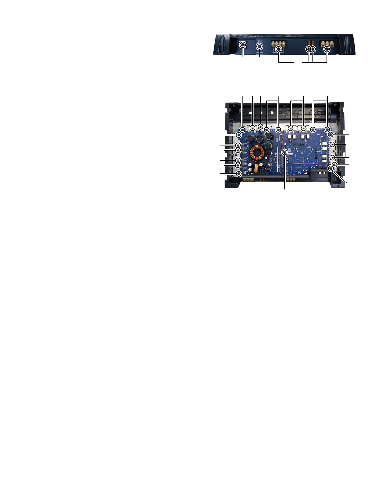
3.1 Main body (Using figures are KS-AR7002)
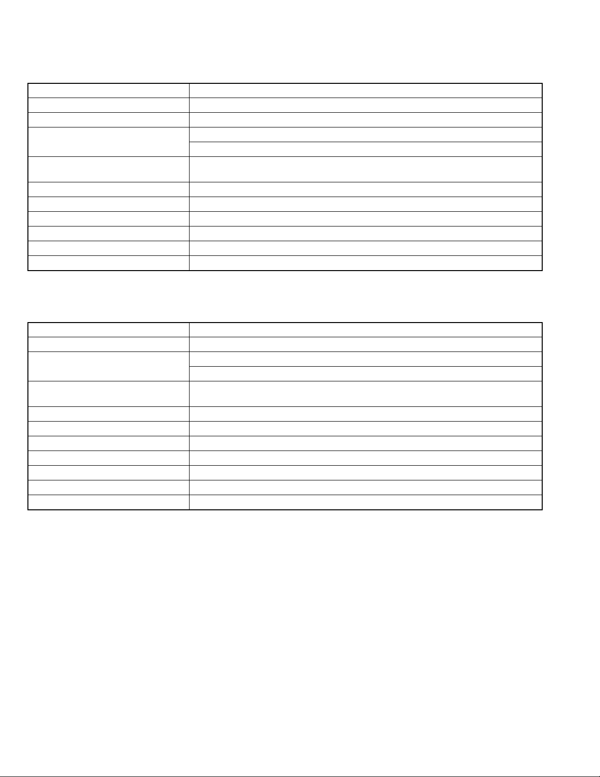
3.1.1 Removing the BOTTOM COVER (See Fig.1)
(1) Remove the twelve screws A attaching the BOTTOM COV-
ER.
A
AA
A
Fig.1
(No.MA347)1-3
Page 4
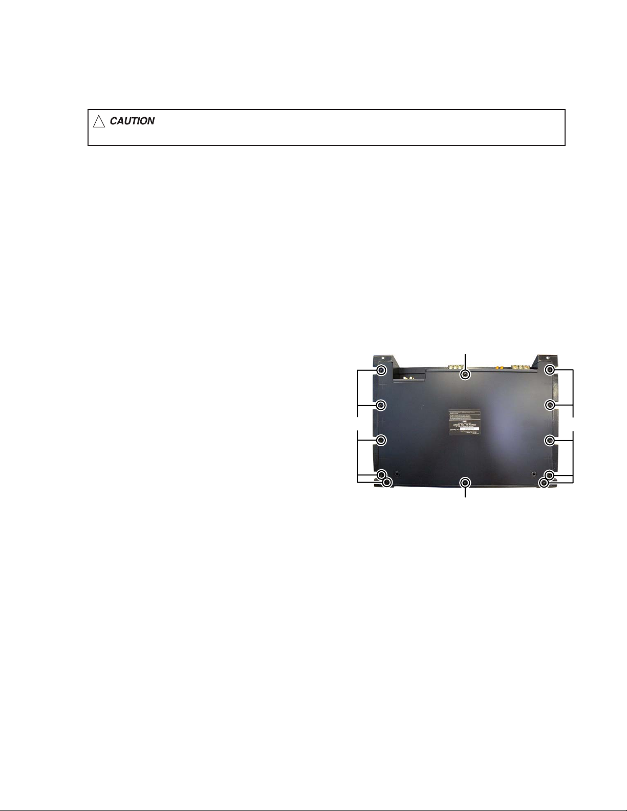
3.1.2 Removing the CROSSOVER BOARD assembly (See
Fig.2, 3)
(1) Remove the two screws B attaching the TOP COVER.
(See Fig.2)
(2) Remove the three knobs.
(3) Disconnect the connector wire from CROSSOVER
BOARD assembly connected to connector CON1
MAIN BOARD assembly. (See Fig.3)
(4) Remove the two screws C attaching the CROSSOVER
BOARD assembly. (See Fig.3)
3.1.3 Removing the LED BOARD assembly (See Fig.3)
(1) Disconnect the connector wire from LED BOARD assem-
bly connected to connector CON2
sembly.
(2) Remove the one screw D attaching the LED BOARD as-
sembly.
of the MAIN BOARD as-
of the
BB
Fig.2
DC
CON1 CON2
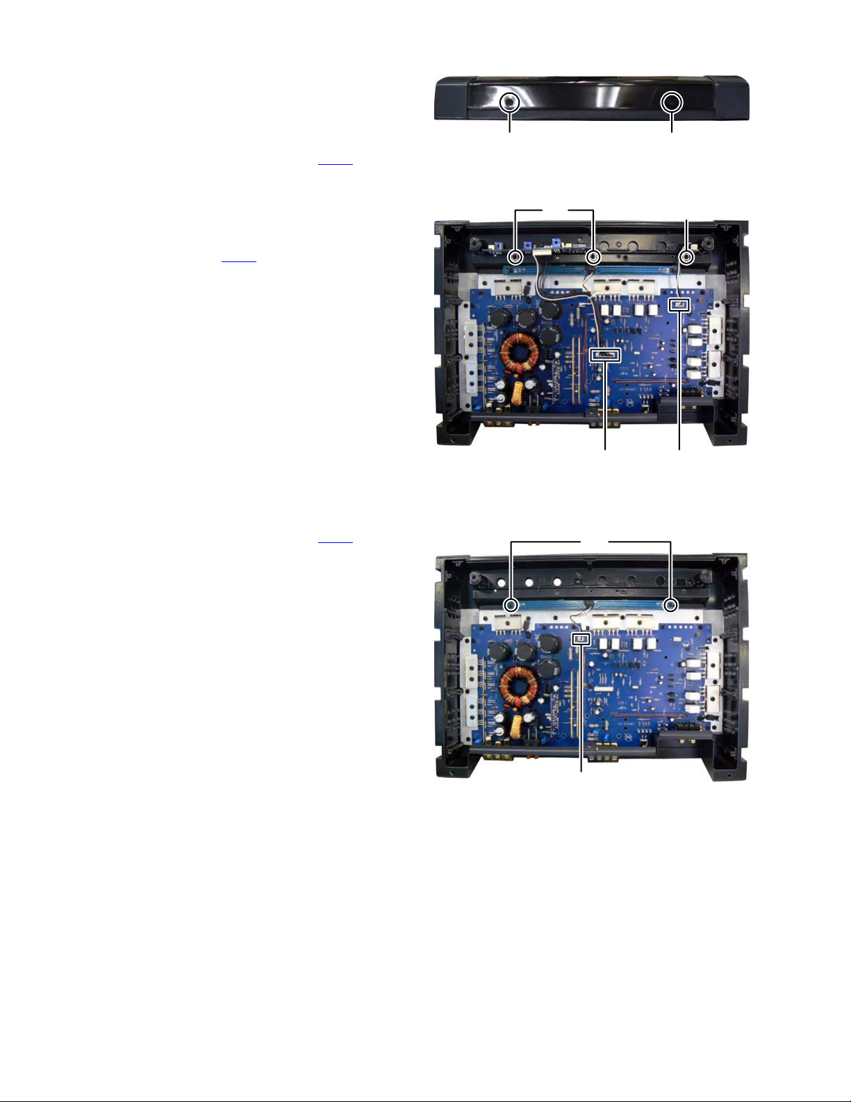
3.1.4 Removing the ILLUMINATOR LED BOARD assembly (See Fig.4)
(1) Disconnect the connector wire from ILLUMINATOR LED
BOARD assembly connected to connector CON3
MAIN BOARD assembly.
(2) Remove the two screws E attaching the ILLUMINATOR
LED BOARD assembly.
of the
Fig.3
E
CON3
Fig.4
1-4 (No.MA347)
Page 5
3.1.5 Removing the MAIN BOARD assembly (See Fig.5, 6)
(1) Remove the five screws F and one screw G attaching the
BACK PANEL. (See Fig.5)
(2) Remove the nine screws H attaching the TRANSISTOR
BRACKET. (See Fig.6)
(3) Remove the two screws J attaching the THERMISTOR.
(See Fig.6)
(4) Remove the nine screws K and one screw L attaching the
MAIN BOARD assembly. (See Fig.6)
GF
KKK
J
F
Fig.5
HH
K
H
H
K
L
Fig.6
SECTION 4
ADJUSTMENT
This service manual does not describe ADJUSTMENT.
K
H
J
K
SECTION 5
TROUBLESHOOTING
This service manual does not describe TROUBLESHOOTING.
(No.MA347)1-5
Page 6

Victor company of Japan, Limited
Mobile Entertainment Business Group Mobile Entertainment Category 10-1,1chome,Ohwatari-machi,Maebashi-city,371-8543,Japan
(No.MA347)
Printed in Japan
VPT
Page 7
PARTS LIST
KS-AR7002J,KS-AX5602E,KS-AX5602U
* All printed circuit boards and its assemblies are not available as service parts.
MA347
- Contents -
Exploded view of general assembly and parts list (Block No.M1)
Electrical parts list (Block No.01~03)
Packing materials and accessories parts list (Block No.M3)
3-2
3-4
3-8
3-1
Page 8
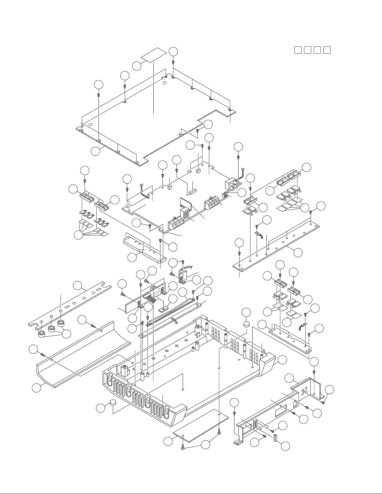
Exploded view of general assembly and parts list
16
34
16
16
Block No.
M
M
1
M
21
16
a
27
15
27
H
27
16
17
27
F
B
c
D
25
27
25
30
27
g
PWM-C board
A
Main board
17
3
22
b
22
22
8
E
Sub board
21
22
19
23
19
33
D
16
H
LED board
19
23
12
B
16
Illuminator board
9
d
G
24
17
24
24
31
18
26
e
f
22
g
18
F
2
20
d
24
20
24
29
31
c
4
a
31
1
22
17
G
28
3-2
10
29
E
b
28
A
e
f
17
6
7
21
17
32
The parts without symbol number are not service.
17
16
17
Page 9

General Assembly
Symbol No. Part No. Part Name Description Local
1 QH700233Z MAIN DIECASTING
2 QH700234Z SUB HEAT SINK
3 QH700235Z SUB HEAT SINK
4 QH700236Z SUB HEAT SINK
6 QP700362Z BACK PANNEL
7 QD700038Z BADGE AR7002J
7 QD700037Z BADGE AX5602E,AX5602U
8 QO400029P TOP CONT SHEET AR7002J
8 QO400025P TOP CONT SHEET AX5602E,AX5602U
9 QK700035Z VOLUME KNOB (x3)
10 QD700035Z TOP COVER
12 QD700036Z ILLUMINATOR
15 QP700366Z BOTTOM COVER
16 QS700060Z SCREW 3X6 T/B(x16)
17 QS700089Z SCREW 3X10 T/B(x18)
18 QS700058Z SCREW 3X8 T/B(x4)
19 QB700092Z TOP BRACKET (x3)
20 QS700055Z SCREW 3X12 T/B(x2)
21 QS700081Z WRENCH SCREW 4X8 M/B(x4)
22 QS700065Z SCREW 3X4 T/B(x8)
23 QS700069Z SCREW 2X6 T/B(x2)
24 QB700060Z TR BRACKET (x5)
25 QB700054Z TR BRACKET (x2)
26 QB700091Z HI INPUT BKT
27 QS700082Z SCREW 3X5 T/B(x9)
28 QS700083Z SCREW 3X6 T/B(x2)
29 QS700025Z RUBBER (x2)
30 QN700023Z MAICA (x6)
31 QN700024Z MAICA (x8)
32 HU500005H FUSE LITTLE 40A(x2)
33 QF700001Z SWITH COVER
34 LV37585-001A NAME PLATE AR7002J
34 LV37586-001A NAME PLATE AX5602E,AX5602U
Block No. [M][1][M][M]
3-3
Page 10

Electrical parts list
Main board
Block No. [0][1]
Symbol No.
ICF1 HI300006C IC NJM 2068(M)
ICF3 HI300006C IC NJM 2068(M)
AB5 KSA1220Y TRANSISTOR HT500006H
FET1 FQP65N06 F.E.T HT500030H
FET2 FQP65N06 F.E.T HT500030H
FET3 FQP65N06 F.E.T HT500030H
FET4 FQP65N06 F.E.T HT500030H
FET5 FQP65N06 F.E.T HT500030H
FET6 FQP65N06 F.E.T HT500030H
QA1 KTC3200GRAT TRANSISTOR HT200011R
QA2 KTC1027 TRANSISTOR HT200019R
QA3 KTC1027 TRANSISTOR HT200019R
QA4 KTC1027 TRANSISTOR HT200019R
QA5 KSA1220Y TRANSISTOR HT500006H
QA6 KSA1220Y TRANSISTOR HT500006H
QA7 KTC3875YRTF TRANSISTOR HT300004C
QA8 IRFP240 F.E.T HT500031H
QA9 IRFP240 F.E.T HT500031H
QA10 IRFP240 F.E.T HT500031H
QA11 IRFP240 F.E.T HT500031H
QB1 KTC3200GRAT TRANSISTOR HT200011R
QB2 KTC1027 TRANSISTOR HT200019R
QB3 KTC1027 TRANSISTOR HT200019R
QB4 KTC1027 TRANSISTOR HT200019R
QB5 KSA1220Y TRANSISTOR HT500006H
QB6 KSA1220Y TRANSISTOR HT500006H
QB7 KTC3875YRTF TRANSISTOR HT300004C
QB8 IRFP240 F.E.T HT500031H
QB9 IRFP240 F.E.T HT500031H
QB10 IRFP240 F.E.T HT500031H
QB11 IRFP240 F.E.T HT500031H
QM1 KRC102SRTKP TRANSISTOR HT300007C
QM2 KTC3875YRTF TRANSISTOR HT300004C
QM3 KTC4373YRTF TRANSISTOR HT300003C
QM4 DTB114ESTP TRANSISTOR HT200003R
QP1 KTC3875YRTF TRANSISTOR HT300004C
QP2 KTA1661YRTF TRANSISTOR HT300002C
QP3 KTA1661YRTF TRANSISTOR HT300002C
QP4 KTA1661YRTF TRANSISTOR HT300002C
QT1 KRC102SRTKP TRANSISTOR HT300007C
D1 MC2838 DIODE HD301008C
D1 or KDS184 DIODE HD301008C
D2 MC2836 DIODE HD301007C
D2 or KDS181 DIODE HD301007C
D3 MC2838 DIODE HD301008C
D3 or KDS184 DIODE HD301008C
D4 MC2836 DIODE HD301007C
D4 or KDS181 DIODE HD301007C
D5 MC2838 DIODE HD301008C
D5 or KDS184 DIODE HD301008C
D6 MC2836 DIODE HD301007C
D6 or KDS181 DIODE HD301007C
DA1 1N4148 DIODE HD100005A
DA3 1SR156-400 DIODE HD301005C
DA4 1SR156-400 DIODE HD301005C
DA5 1N4148 DIODE HD100005A
DA6 1N4148 DIODE HD100005A
DA7 1SR156-400 DIODE HD301005C
DA8 1SR156-400 DIODE HD301005C
DA9 1N4148 DIODE HD100005A
DB1 1N4148 DIODE HD100005A
DB3 1SR156-400 DIODE HD301005C
DB4 1SR156-400 DIODE HD301005C
DB5 1N4148 DIODE HD100005A
DB6 1N4148 DIODE HD100005A
DB7 1SR156-400 DIODE HD301005C
DB8 1SR156-400 DIODE HD301005C
DB9 1N4148 DIODE HD100005A
DM1 1N4148 DIODE HD100005A
DP1 URF1020C RECTFIAER DIODE HD500006H
Part No. Part Name Description Local
Symbol No.
DP2 P4KE DIODE HD100006A
DP3 FR104 DIODE HD100003A
DP4 FMG32S RECTFIAER DIODE HD500010H
DP5 FMG32R RECTFIAER DIODE HD500009H
DP6 1N4148 DIODE HD100005A
DP7 1N4148 DIODE HD100005A
DR1 1N4148 DIODE HD100005A
DR2 1N4148 DIODE HD100005A
DX1 FR104 DIODE HD100003A
DX2 FR104 DIODE HD100003A
DX3 FR104 DIODE HD100003A
DX4 FR104 DIODE HD100003A
LED1A HL500003H LED 3PHI BLUE
LED2A HL500003H LED 3PHI BLUE
LEDA2 HL500003H LED 3PHI BLUE
LEDS1 HL500010H LED 3PHI G/R 2COLOR
ZD1 1W15V Z DIODE HD104007A
ZD2 1W15V Z DIODE HD104007A
ZDR1 1W43V Z DIODE HD104010A
ZDR2 1W43V Z DIODE HD104010A
C1 HC202008R E CAPACITOR 16V 220uF
CA1 HC202006R E CAPACITOR 16V 47uF
CA2 HC300010C CHIP CAPACITOR 2012 560P
CA3 HC202007R E CAPACITOR 16V 100uF
CA4 HC300004C CHIP CAPACITOR 2012 102
CA5 HC300012C CHIP CAPACITOR 2012 473
CA6 HC202029R E CAPACITOR 16V 470uF
CA7 HC300001C CHIP CERAMIC 2012 68P
CA8 HC206015R MYLAR CAPACITOR 104J 100V (104)
CA9 HC300002C CHIP CAPACITOR 2012 100P
CB1 HC202006R E CAPACITOR 16V 47uF
CB2 HC300010C CHIP CAPACITOR 2012 560P
CB3 HC202007R E CAPACITOR 16V 100uF
CB4 HC300004C CHIP CAPACITOR 2012 102
CB5 HC300012C CHIP CAPACITOR 2012 473
CB6 HC202029R E CAPACITOR 16V 470uF
CB7 HC300001C CHIP CERAMIC 2012 68P
CB8 HC206015R MYLAR CAPACITOR 104J 100V (104)
CB9 HC300002C CHIP CAPACITOR 2012 100P
CF1A HC202004R E CAPACITOR 16V 10uF
CF1B HC202004R E CAPACITOR 16V 10uF
CF2A HC202004R E CAPACITOR 16V 10uF
CF2B HC202004R E CAPACITOR 16V 10uF
CF3A HC300002C CHIP CAPACITOR 2012 100P
CF3B HC300002C CHIP CAPACITOR 2012 100P
CF4A HC300002C CHIP CAPACITOR 2012 100P
CF4B HC300002C CHIP CAPACITOR 2012 100P
CF5A HC202005R E CAPACITOR 16V 22uF
CF5B HC202005R E CAPACITOR 16V 22uF
CF6A HC202005R E CAPACITOR 16V 22uF
CF6B HC202005R E CAPACITOR 16V 22uF
CFS2 HC202006R E CAPACITOR 16V 47uF
CFS3 HC202006R E CAPACITOR 16V 47uF
CG1 HC206015R MYLAR CAPACITOR 104J 100V (104)
CG2 HC200015R CERAMIC 103
CG3 HC200019R CERAMIC 563
CG4 HC200008R CERAMIC 220P
CG5 HC200008R CERAMIC 220P
CH1 HC300002C CHIP CAPACITOR 2012 100P
CH2 HC300002C CHIP CAPACITOR 2012 100P
CH3 HC300002C CHIP CAPACITOR 2012 100P
CH4 HC300002C CHIP CAPACITOR 2012 100P
CHS4 HC300007C CHIP CAPACITOR 2012 104
CHS5 HC300007C CHIP CAPACITOR 2012 104
CK1 HC305003C CHIP CAPACITOR 3216 25V 1.5uF
CK2 HC202006R E CAPACITOR 16V 47uF
CK4 HC206004R MYLAR CAPACITOR 472J100V (472)
CK5 HC206004R MYLAR CAPACITOR 472J100V (472)
CK6 HC300007C CHIP CAPACITOR 2012 104
CM1 HC202006R E CAPACITOR 16V 47uF
CM2 HC202007R E CAPACITOR 16V 100uF
CP1 HC300007C CHIP CAPACITOR 2012 104
CP2 HC300014C CHIP CAPACITOR 2012 224
CP3 HC206015R MYLAR CAPACITOR 104J 100V (104)
CP4 HC202028R E CAPACITOR 25V 220uF
Part No. Part Name Description Local
3-4
Page 11

Symbol No.
Part No. Part Name Description Local
Symbol No.
Part No. Part Name Description Local
CP5 HC205011R METAL CAPACITOR 100nJ 100V (104)
CP6 HC300008C CHIP CAPACITOR 2012 222
CP7 HC300007C CHIP CAPACITOR 2012 104
CP8 HC202024R E CAPACITOR 35V 47uF
CP9 HC300014C CHIP CAPACITOR 2012 224
CP13 HC500004H E CAPACITOR 35V 680uF
CP14 HC500004H E CAPACITOR 35V 680uF
CP15 HC202029R E CAPACITOR 16V 470uF
CP16 HC202029R E CAPACITOR 16V 470uF
CP17 HC500018H E CAPACITOR 16V 3300uF
CP18 HC500018H E CAPACITOR 16V 3300uF
CP19 HC500018H E CAPACITOR 16V 3300uF
CP20 HC300014C CHIP CAPACITOR 2012 224
CP21 HC300008C CHIP CAPACITOR 2012 222
CP22 HC500023H E CAPACITOR 50V 4700uF
CP23 HC500023H E CAPACITOR 50V 4700uF
CP24 HC500023H E CAPACITOR 50V 4700uF
CP25 HC500023H E CAPACITOR 50V 4700uF
CPX21 HC300014C CHIP CAPACITOR 2012 224
CU1 HC300007C CHIP CAPACITOR 2012 104
CU2 HC300007C CHIP CAPACITOR 2012 104
JA1 HR300031C CHIP RESISTOR 2012 0
JB1 HR300031C CHIP RESISTOR 2012 0
JS4 HR300031C CHIP RESISTOR 2012 0
R1 HR300019C CHIP RESISTOR 2012 4.7 K
R1A HR300048C CHIP RESISTOR 2012 560
RA2 HR305008C CHIP RESISTOR 3216 4.7 K
RA3 HR305017C CHIP RESISTOR 3216 2.2 K
RA4 HR305014C CHIP RESISTOR 3216 620
RA5 HR305016C CHIP RESISTOR 3216 15 KΩ1%
RA6 HR305018C CHIP RESISTOR 3216 39 K
RA7 HR300019C CHIP RESISTOR 2012 4.7 K
RA8 HR305011C CHIP RESISTOR 3216 4.99 KΩ1%
RA9 HR305011C CHIP RESISTOR 3216 4.99 KΩ1%
RA10 HR305011C CHIP RESISTOR 3216 4.99 KΩ1%
RA11 HR305013C CHIP RESISTOR 3216 60.4 Ω1%
RA12 HR305010C CHIP RESISTOR 3216 470
RA13 HR305013C CHIP RESISTOR 3216 60.4 Ω1%
RA14 HR305021C CHIP RESISTOR 3216 620 Ω1%
RA15 HR107019A C.F RESISTOR 1/8W 820 Ω1%
RA16 HR107019A C.F RESISTOR 1/8W 820 Ω1%
RA17 HR305015C CHIP RESISTOR 3216 12 K
RA18 HR300020C CHIP RESISTOR 2012 47 K
RA19 HR300020C CHIP RESISTOR 2012 47 K
RA20 HR108002A M.O RESISTOR 1W 4.7
RA21 HR103064A C.F RESISTOR 1/4W 1.2 KΩ1%
RA22 HR103013A C.F RESISTOR 1/4W 100 Ω1%
RA23 HR103013A C.F RESISTOR 1/4W 100 Ω1%
RA24 HR103013A C.F RESISTOR 1/4W 100
RA25 HR103013A C.F RESISTOR 1/4W 100 Ω1%
RA26 HR505001H M.P.R 5W 0.1
RA27 HR505001H M.P.R 5W 0.1
RA28 HR505001H M.P.R 5W 0.1 Ω(R-TYPE)
RA29 HR505001H M.P.R 5W 0.1
RA30 HR300006C CHIP RESISTOR 2012 100 K
RA31 HR300006C CHIP RESISTOR 2012 100 K
RA32 HR300006C CHIP RESISTOR 2012 100 K
RA33 HR300006C CHIP RESISTOR 2012 100 K
RA221 HR103064A C.F RESISTOR 1/4W 1.2 KΩ1%
RB1 HR305019C CHIP RESISTOR 3216 560
RB2 HR305008C CHIP RESISTOR 3216 4.7 K
RB3 HR305017C CHIP RESISTOR 3216 2.2 K
RB4 HR305014C CHIP RESISTOR 3216 620
RB5 HR305016C CHIP RESISTOR 3216 15 KΩ1%
RB6 HR305018C CHIP RESISTOR 3216 39 K
RB7 HR300019C CHIP RESISTOR 2012 4.7 K
RB8 HR305011C CHIP RESISTOR 3216 4.99 KΩ1%
RB9 HR305011C CHIP RESISTOR 3216 4.99 K
RB10 HR305011C CHIP RESISTOR 3216 4.99 KΩ1%
RB11 HR305013C CHIP RESISTOR 3216 60.4
RB12 HR305010C CHIP RESISTOR 3216 470
RB13 HR305013C CHIP RESISTOR 3216 60.4 Ω1%
RB14 HR305021C CHIP RESISTOR 3216 620
RB15 HR107019A C.F RESISTOR 1/8W 820
RB16 HR107019A C.F RESISTOR 1/8W 820 Ω1%
RB17 HR305015C CHIP RESISTOR 3216 12 K
RB18 HR300020C CHIP RESISTOR 2012 47 K
Ω
Ω
Ω
Ω
Ω
Ω
Ω
Ω
Ω
Ω
Ω
Ω
Ω
Ω
Ω
Ω
1%
Ω
(R-TYPE)
Ω
(R-TYPE)
Ω
(R-TYPE)
Ω
Ω
Ω
Ω
Ω
Ω
Ω
Ω
Ω
Ω
Ω
Ω
1%
Ω
Ω
1%
Ω
1%
Ω
Ω
1%
RB19 HR300020C CHIP RESISTOR 2012 47 K
RB20 HR108002A M.O RESISTOR 1W 4.7
RB21 HR103064A C.F RESISTOR 1/4W 1.2 KΩ1%
RB22 HR103013A C.F RESISTOR 1/4W 100 Ω1%
RB23 HR103013A C.F RESISTOR 1/4W 100 Ω1%
RB24 HR103013A C.F RESISTOR 1/4W 100
RB25 HR103013A C.F RESISTOR 1/4W 100
RB26 HR505001H M.P.R 5W 0.1 Ω(R-TYPE)
RB27 HR505001H M.P.R 5W 0.1 Ω(R-TYPE)
RB28 HR505001H M.P.R 5W 0.1 Ω(R-TYPE)
RB29 HR505001H M.P.R 5W 0.1 Ω(R-TYPE)
RB30 HR300006C CHIP RESISTOR 2012 100 K
RB31 HR300006C CHIP RESISTOR 2012 100 K
RB32 HR300006C CHIP RESISTOR 2012 100 K
RB33 HR300006C CHIP RESISTOR 2012 100 K
RB221 HR103064A C.F RESISTOR 1/4W 1.2 KΩ1%
RE1 HR300052C CHIP RESISTOR 2012 1 KΩ1%
RE2 HR300052C CHIP RESISTOR 2012 1 KΩ1%
RF1A HR300012C CHIP RESISTOR 2012 22 K
RF1B HR300012C CHIP RESISTOR 2012 22 K
RF2A HR300012C CHIP RESISTOR 2012 22 K
RF2B HR300012C CHIP RESISTOR 2012 22 K
RF3A HR300012C CHIP RESISTOR 2012 22 K
RF3B HR300012C CHIP RESISTOR 2012 22 K
RF4A HR300012C CHIP RESISTOR 2012 22 K
RF4B HR300012C CHIP RESISTOR 2012 22 K
RF5A HR305017C CHIP RESISTOR 3216 2.2 K
RF5B HR305017C CHIP RESISTOR 3216 2.2 K
RF6A HR107064A C.F RESISTOR 1/8W 100 KΩ1%
RF6B HR107064A C.F RESISTOR 1/8W 100 KΩ1%
RF7A HR107064A C.F RESISTOR 1/8W 100 KΩ1%
RF7B HR107064A C.F RESISTOR 1/8W 100 KΩ1%
RF8A HR300020C CHIP RESISTOR 2012 47 K
RF8B HR300020C CHIP RESISTOR 2012 47 K
RH1 HR103051A C.F RESISTOR 1/4W 47 KΩ1%
RH2 HR300011C CHIP RESISTOR 2012 2.7 K
RH3 HR103051A C.F RESISTOR 1/4W 47 KΩ1%
RH4 HR300011C CHIP RESISTOR 2012 2.7 K
RK1 HR100002A C.F RESISTOR 1/2W 10 Ω(Small)
RK2 HR100002A C.F RESISTOR 1/2W 10 Ω(Small)
RK3 HR305001C CHIP RESISTOR 3216 1 K
RL1 HR300010C CHIP RESISTOR 2012 2.2 K
RL2 HR300021C CHIP RESISTOR 2012 470
RM1 HR300023C CHIP RESISTOR 2012 5.6 K
RM2 HR300003C CHIP RESISTOR 2012 10 K
RM3 HR300014C CHIP RESISTOR 2012 220 K
RM4 HR300010C CHIP RESISTOR 2012 2.2 K
RM5 HR300010C CHIP RESISTOR 2012 2.2 K
RP1 HR300012C CHIP RESISTOR 2012 22 K
RP2 HR300010C CHIP RESISTOR 2012 2.2 K
RP3 HR300016C CHIP RESISTOR 2012 3.3 K
RP4 HR300019C CHIP RESISTOR 2012 4.7 K
RP5 HR100009A C.F RESISTOR 1/2W 4.7 Ω(Small)
RP6 HR103020A C.F RESISTOR 1/4W 1 KΩ1%
RP7 HR108004A M.O RESISTOR 1W 22
RP8 HR300021C CHIP RESISTOR 2012 470
RP9 HR108005A M.O RESISTOR 1W 33 Ω(R-TYPE)
RP11 HR103036A C.F RESISTOR 1/4W 10 K
RP12 HR103036A C.F RESISTOR 1/4W 10 KΩ1%
RP13 HR108019A M.O RESISTOR 1W 68
RP14 HR108019A M.O RESISTOR 1W 68
RP15 HR300016C CHIP RESISTOR 2012 3.3 K
RP16 HR107011A C.F RESISTOR 1/8W 220 Ω1%
RP17 HR107011A C.F RESISTOR 1/8W 220
RP18 HR103009A C.F RESISTOR 1/4W 47 Ω1%
RP19 HR103009A C.F RESISTOR 1/4W 47
RP20 HR103009A C.F RESISTOR 1/4W 47
RP21 HR103009A C.F RESISTOR 1/4W 47
RP22 HR103009A C.F RESISTOR 1/4W 47
RP23 HR103009A C.F RESISTOR 1/4W 47 Ω1%
RP24 HR500046H M.O RESISTOR 2W 4.7K
RP25 HR500046H M.O RESISTOR 2W 4.7K
RPS1 HR300023C CHIP RESISTOR 2012 5.6 K
RPS2 HR300019C CHIP RESISTOR 2012 4.7 K
RR1 HR300021C CHIP RESISTOR 2012 470
RR2 HR300010C CHIP RESISTOR 2012 2.2 K
RS1A HR300033C CHIP RESISTOR 2012 100
RS1B HR300033C CHIP RESISTOR 2012 100
Ω
Ω
Ω
1%
Ω
1%
Ω
Ω
Ω
Ω
Ω
Ω
Ω
Ω
Ω
Ω
Ω
Ω
Ω
Ω
Ω
Ω
Ω
Ω
Ω
Ω
Ω
Ω
Ω
Ω
Ω
Ω
Ω
Ω
Ω
Ω
Ω
(R-TYPE)
Ω
Ω
1%
Ω
Ω
Ω
Ω
1%
Ω
1%
Ω
1%
Ω
1%
Ω
1%
Ω
(FORMING)
Ω
(FORMING)
Ω
Ω
Ω
Ω
Ω
Ω
3-5
Page 12

Symbol No.
Part No. Part Name Description Local
Symbol No.
Part No. Part Name Description Local
RU1 HR300011C CHIP RESISTOR 2012 2.7 K
RU2 HR300011C CHIP RESISTOR 2012 2.7 K
SE1 HR107023A C.F RESISTOR 1/8W 1.5 KΩ1%
SE2 HR107023A C.F RESISTOR 1/8W 1.5 KΩ1%
TRH1 HR300006C CHIP RESISTOR 2012 100 K
L1 HO501201H-3 BEED ATS 3550
L2 HO501201H-3 BEED ATS 3550
L3 HO501201H-3 BEED ATS 3550
L4 HO501201H-3 BEED ATS 3550
CON1 HK502506H WAFER YMW 025-09P
CON2 HK502504H WAFER YMW 025-03P
CON3 HK502505H WAFER YMW 025-02P
CON2-1 HE503026H CONNECTOR WIRE #26 3P 100M/M
CON3-1 HE503025H CONNECTOR WIRE #26 2P 80M/M
FUSE1 HH500007H FUSE HOLD BXS02-10
HI1 HE503020H HI INPUT 4P MOLD
JP1 HJ502004H JUMP PLATE 5P GOLD 15m/m pitch
JP2 HJ502003H JUMP PLATE 4P GOLD 15m/m pitch
JP3 HO501201H-4 CUPPER WIRE 2PHI 90m/m
JP4 HO501201H-5 CUPPER WIRE 2PHI 100m/m
JP5 HO501201H-5 CUPPER WIRE 2PHI 100m/m
JP6 HO501201H-4 CUPPER WIRE 2PHI 90m/m
RCA1 HK501013H RCA JACK AV4-8 4-38 (R/W)
RFC1 HO501201H-2 RFC 27PHI 11L 5T
TER1 HM505017H TERMINAL WB03-33GDTH
TER2 HM505019H TERMINAL WB04-34GDTH
TH1 HR506004H THERMISTOR NTC5D-153H25-BK
TH2 HR506004H THERMISTOR NTC5D-153H25-BK
TRANS1 HO501201H-1 POWER TRANS 4916 5/16/8 T1=4T
2.5mm pitch
2.5mm pitch
(H= 15m/m)
(H= 15m/m)
(H= 15m/m)
(H= 15m/m)
(MILKY)
(MILKY)
(MOLD)
(MOLD)
(4T/8T=7)
Ω
Ω
Ω
PWM-C board
Block No. [0][2]
Symbol No.
Part No. Part Name Description Local
C9 HC300007C CHIP CAPACITOR 2012 104
C10 HC300007C CHIP CAPACITOR 2012 104
C11 HC300007C CHIP CAPACITOR 2012 104
CB1 HC300007C CHIP CAPACITOR 2012 104
CB2 HC300007C CHIP CAPACITOR 2012 104
CG1 HC300007C CHIP CAPACITOR 2012 104
CS1 HC202032R E CAPACITOR 100V 10uF
CS2 HC202007R E CAPACITOR 16V 100uF
CX1 HC300004C CHIP CAPACITOR 2012 102
R1 HR300003C CHIP RESISTOR 2012 10 K
R2 HR300001C CHIP RESISTOR 2012 1 K
R3 HR300011C CHIP RESISTOR 2012 2.7 K
R4 HR300011C CHIP RESISTOR 2012 2.7 K
R6 HR300004C CHIP RESISTOR 2012 15 K
R7 HR300053C CHIP RESISTOR 2012 20 K
R8 HR300022C CHIP RESISTOR 2012 470 K
R9 HR300011C CHIP RESISTOR 2012 2.7 K
R10 HR300011C CHIP RESISTOR 2012 2.7 K
R11 HR300005C CHIP RESISTOR 2012 18 K
R12 HR300017C CHIP RESISTOR 2012 33 K
R13 HR300017C CHIP RESISTOR 2012 33 K
R14 HR300021C CHIP RESISTOR 2012 470
R16 HR300041C CHIP RESISTOR 2012 3.9 K
R19 HR300002C CHIP RESISTOR 2012 1 M
R20 HR300019C CHIP RESISTOR 2012 4.7 K
R21 HR300005C CHIP RESISTOR 2012 18 K
R22 HR300026C CHIP RESISTOR 2012 1 K
R23 HR300026C CHIP RESISTOR 2012 1 K
RB1 HR300019C CHIP RESISTOR 2012 4.7 K
RB2 HR300003C CHIP RESISTOR 2012 10 K
RG1 HR300001C CHIP RESISTOR 2012 1 K
RG2 HR300003C CHIP RESISTOR 2012 10 K
RG3 HR300016C CHIP RESISTOR 2012 3.3 K
RG4 HR300025C CHIP RESISTOR 2012 6.8 K
RG5 HR300025C CHIP RESISTOR 2012 6.8 K
RG6 HR300025C CHIP RESISTOR 2012 6.8 K
RG7 HR300003C CHIP RESISTOR 2012 10 K
RG8 HR300010C CHIP RESISTOR 2012 2.2 K
RS1 HR300011C CHIP RESISTOR 2012 2.7 K
RS2 HR300003C CHIP RESISTOR 2012 10 K
RS3 HR300020C CHIP RESISTOR 2012 47 K
RS4 HR300019C CHIP RESISTOR 2012 4.7 K
RS5 HR300003C CHIP RESISTOR 2012 10 K
PIN1 HK502502H WAFER FAU0640-06P
PIN2 HK502503H WAFER FAU0640-07P
PIN3 HK502501H WAFER FAU0640-03P
Ω
Ω
Ω
Ω
Ω
Ω
Ω
Ω
Ω
Ω
Ω
Ω
Ω
Ω
Ω
Ω
Ω
Ω
Ω
Ω
Ω
Ω
Ω
Ω
Ω
Ω
Ω
Ω
Ω
Ω
Ω
Ω
Ω
Ω
IC1 HI500005H IC KIA494AF
IC2 HI300002C IC NJM2904M
IC3 HI300002C IC NJM2904M
QB1 KTC4373YRTF TRANSISTOR HT300003C
QB2 KTC3875YRTF TRANSISTOR HT300004C
QB3 KTC3875YRTF TRANSISTOR HT300004C
QS1 KTA1661YRTF TRANSISTOR HT300002C
D1 LL4148 SWITCH DIODE HD300001C
D2 LL4148 SWITCH DIODE HD300001C
D3 LL4148 SWITCH DIODE HD300001C
D4 LL4148 SWITCH DIODE HD300001C
DB1 LL4148 SWITCH DIODE HD300001C
DG1 LL4148 SWITCH DIODE HD300001C
DG2 LL4148 SWITCH DIODE HD300001C
DS1 LL4148 SWITCH DIODE HD300001C
DS2 LL4148 SWITCH DIODE HD300001C
ZG1 HD301004C Z DIODE 201215V
ZG2 HD301003C Z DIODE 20126.2V
C1 HC202007R E CAPACITOR 16V 100uF
C2 HC202007R E CAPACITOR 16V 100uF
C3 HC202007R E CAPACITOR 16V 100uF
C4 HC202001R E CAPACITOR 50V 0.1uF
C6 HC205001R TF CAPACITOR 102
C7 HC205004R METAL CAPACITOR 47nJ 100V (473)
C8 HC300007C CHIP CAPACITOR 2012 104
3-6
Sub1 board
Block No. [0][3]
Symbol No.
ICF5 HI300006C IC NJM 2068(M)
ICF6 HI300006C IC NJM 2068(M)
ICF7 HI300006C IC NJM 2068(M)
ICS1 HI300006C IC NJM 2068(M)
ICS2 HI300006C IC NJM 2068(M)
ICS3 HI300006C IC NJM 2068(M)
ICS4 HI300006C IC NJM 2068(M)
ICS5 HI300006C IC NJM 2068(M)
ICS6 HI300006C IC NJM 2068(M)
ICS7 HI300006C IC NJM 2068(M)
ICX1 HI300006C IC NJM 2068(M)
CF7A HC300015C CHIP CAPACITOR 2012 47P
CF7B HC300015C CHIP CAPACITOR 2012 47P
CF8A HC300004C CHIP CAPACITOR 2012 102
CF8B HC300004C CHIP CAPACITOR 2012 102
CF9A HC202002R E CAPACITOR 50V 2.2uF
CF9B HC202002R E CAPACITOR 50V 2.2uF
CF10A HC205011R METAL CAPACITOR 100nJ 100V (104)
CF10B HC205011R METAL CAPACITOR 100nJ 100V (104)
Part No. Part Name Description Local
Page 13

Symbol No.
CS1 HC202006R E CAPACITOR 16V 47uF
CS2 HC202006R E CAPACITOR 16V 47uF
CS1A HC300015C CHIP CAPACITOR 2012 47P
CS1B HC300015C CHIP CAPACITOR 2012 47P
CS2A HC205013R METAL CAPACITOR 82nJ 100V (823)
CS2B HC205013R METAL CAPACITOR 82nJ 100V (823)
CS3A HC205013R METAL CAPACITOR 82nJ 100V (823)
CS3B HC205013R METAL CAPACITOR 82nJ 100V (823)
CS4A HC205013R METAL CAPACITOR 82nJ 100V (823)
CS4B HC205013R METAL CAPACITOR 82nJ 100V (823)
CS5A HC305002C CHIP CAPACITOR 3216 224
CS5B HC305002C CHIP CAPACITOR 3216 224
CS6A HC305002C CHIP CAPACITOR 3216 224
CS6B HC305002C CHIP CAPACITOR 3216 224
Part No. Part Name Description Local
JS1 HR300031C CHIP RESISTOR 2012 0
RF9A HR300010C CHIP RESISTOR 2012 2.2 K
RF9B HR300010C CHIP RESISTOR 2012 2.2 K
RF10A HR300019C CHIP RESISTOR 2012 4.7 K
RF10B HR300019C CHIP RESISTOR 2012 4.7 K
RF11A HE503075H CHIP RESISTOR 2012 68 K
RF11B HE503075H CHIP RESISTOR 2012 68 K
RF12A HR300020C CHIP RESISTOR 2012 47 K
RF12B HR300020C CHIP RESISTOR 2012 47 K
RF13A HR300019C CHIP RESISTOR 2012 4.7 K
RF13B HR300019C CHIP RESISTOR 2012 4.7 K
RF14A HR300003C CHIP RESISTOR 2012 10 K
RF14B HR300003C CHIP RESISTOR 2012 10 K
RF15A HR300041C CHIP RESISTOR 2012 3.9 K
RF15B HR300041C CHIP RESISTOR 2012 3.9 K
RF16A HR300021C CHIP RESISTOR 2012 470
RF16B HR300021C CHIP RESISTOR 2012 470
RF17A HR300037C CHIP RESISTOR 2012 120 KΩ1%
RF17B HR300037C CHIP RESISTOR 2012 120 KΩ1%
RS1 HR300003C CHIP RESISTOR 2012 10 K
RS2A HR300020C CHIP RESISTOR 2012 47 K
RS2B HR300020C CHIP RESISTOR 2012 47 K
RS3A HR300003C CHIP RESISTOR 2012 10 K
RS3B HR300003C CHIP RESISTOR 2012 10 K
RS4A HR300003C CHIP RESISTOR 2012 10 K
RS4B HR300003C CHIP RESISTOR 2012 10 K
RS5A HR300003C CHIP RESISTOR 2012 10 K
RS5B HR300003C CHIP RESISTOR 2012 10 K
RS6A HR300041C CHIP RESISTOR 2012 3.9 K
RS6B HR300041C CHIP RESISTOR 2012 3.9 K
RS7A HR300041C CHIP RESISTOR 2012 3.9 K
RS7B HR300041C CHIP RESISTOR 2012 3.9 K
RS8A HR300041C CHIP RESISTOR 2012 3.9 K
RS8B HR300041C CHIP RESISTOR 2012 3.9 K
RS9A HR300003C CHIP RESISTOR 2012 10 K
RS9B HR300003C CHIP RESISTOR 2012 10 K
RS10A HR300019C CHIP RESISTOR 2012 4.7 K
RS10B HR300019C CHIP RESISTOR 2012 4.7 K
RS11A HR300019C CHIP RESISTOR 2012 4.7 K
RS11B HR300019C CHIP RESISTOR 2012 4.7 K
RS12A HE503075H CHIP RESISTOR 2012 68 K
RS12B HE503075H CHIP RESISTOR 2012 68 K
RS13A HR300049C CHIP RESISTOR 2012 56 K
RS13B HR300049C CHIP RESISTOR 2012 56 K
RS14A HR300003C CHIP RESISTOR 2012 10 K
RS14B HR300003C CHIP RESISTOR 2012 10 K
RS15A HR300003C CHIP RESISTOR 2012 10 K
RS15B HR300003C CHIP RESISTOR 2012 10 K
RS16A HR300020C CHIP RESISTOR 2012 47 K
RS16B HR300020C CHIP RESISTOR 2012 47 K
RS17A HR300054C CHIP RESISTOR 2012 22
RS17B HR300054C CHIP RESISTOR 2012 22
RX1 HR300003C CHIP RESISTOR 2012 10 K
RX2 HR300003C CHIP RESISTOR 2012 10 K
VR1 HV500048H VOLUME V09M 3B20KX2
VR2 HV500049H VOLUME V09M 15C10KX2
CON1-1 HE503027H CONNECTOR WIRE #26 9P 210M/M
SW1 HW501012H SWITCH KSA2342T (9)
VRS1 HV500052H VOLUME V09M 15C50KX6
Ω
Ω
Ω
Ω
Ω
Ω
Ω
Ω
Ω
Ω
Ω
Ω
Ω
Ω
Ω
Ω
Ω
Ω
Ω
Ω
Ω
Ω
Ω
Ω
Ω
Ω
Ω
Ω
Ω
Ω
Ω
Ω
Ω
Ω
Ω
Ω
Ω
Ω
Ω
Ω
Ω
Ω
Ω
Ω
Ω
Ω
Ω
Ω
Ω
Ω
Ω
Ω
(S=10mm)NEW
(S=10mm)NEW
2.5mm pitch
(S=10mm)NEW
3-7
Page 14

Packing materials and accessories parts list
No additional / supplemental order of WARRANTY CARDs are available.
P5
P7
A14
P6
A1,A2,A3,
A4,A5,A6,A7,A8
P4
P3
P2
Block No.
P7
3
M
A9,A10,A11,A12
A13
M
P7
M
P6
A16
A15
P1
3-8
The parts without symbol number are not service.
Page 15

Packing and Accessories
Symbol No. Part No. Part Name Description Local
A 1 LVT1700-001A INST BOOK ENG FRE AR7002J
A 1 LVT1697-001A INST BOOK ENG FRE AX5602E,AX5602U
A 2 LVT1700-002A INST BOOK SPA AR7002J
A 2 LVT1697-002A INST BOOK SPA AX5602E
A 2 LVT1697-006A INST BOOK CHI THA AX5602U
A 3 LVT1697-003A INST BOOK GER ITA AX5602E
A 3 LVT1697-007A INST BOOK ARA PER AX5602U
A 4 LVT1697-004A INST BOOK DUT SWE AX5602E
A 5 LVT1697-005A INST BOOK RUS UKR AX5602E
A 6 ------------ WARRANTY CARD BT-51029-3 AR7002J
A 6 ------------ WARRANTY CARD BT-54031-1 AX5602E
A 7 ------------ WARRANTY CARD BT-52006-2 AR7002J
A 8 BT-51041-1 REGIS. CARD AR7002J
A 9 QS700021Z L WRENCH
A 10 QS700022Z L WRENCH
A 11 QS700043Z SCREW (x4)
A 12 QS700051Z SCREW (x6)
A 13 QS700025Z RUBBER (x6)
A 14 HE503024H HI INPUT TAP #20 4P 200m/m(WHITE/GRAY)
A 15 QS700023Z S TPYE BRACKET (x2)
A 16 QS700024Z L TPYE BRACKET
P 1 LV37736-001A CARTON AR7002J
P 1 LV37686-005A CARTON AX5602E,AX5602U
P 2 LV22528-002A POLY FOAM R
P 3 LV22528-001A POLY FOAM L
P 4 QO400010P POLY BAG FOR AMP
P 5 QC400325P CARTON PAD
P 6 QO400015P POLY BAG FOR BOOKLET BAG/PARTS BAG-4(x2)
P 7 QO400014P POLY BAG FOR PARTS BAG1-3(x3)
Block No. [M][3][M][M]
3-9
Page 16

SCHEMATIC DIAGRAMS
POWER AMPLIFIER
KS-AR7002J,KS-AX5602E,KS-AX5602U
CD-ROM No.SML200708
KS-AR7002
Lead free solder used in the board (material : Sn-Ag-Cu, melting point : 219 Centigrade)
Contents
Block diagram
Standard schematic diagrams
Printed circuit boards
COPYRIGHT 2007 Victor Company of Japan, Limited.
2-1
2-2
2-5 to 6
KS-AX5602
No.MA347SCH
2007/8
Page 17

Safety precaution
!
Burrs formed during molding may be left over on some parts of the chassis. Therefore,
pay attention to such burrs in the case of preforming repair of this system.
Page 18

Block diagram
MAIN section
LCH
LINE
OUTPUT
RCH
RCA1
ICF3
AMP.
LINE INPUT
(LOW)
LINE INPUT
(HIGH)
SPEAKER
HI1
TER2
FRONT L/R
FRONT L/R
ICF1
FRONT
LINEIN AMP.
QA7 to QA11
QB7 to QB11
PROTECT
DC PROTECT
SHORT PROTECT
ICF5,VR1
LEVEL
ADJ.
QA3 to QA6
QB3 to QB6
AMP.
QA1,QA2
QB1,QB2
QM1 to QM4
MUTE
FL
FR
ICF6,ICF7
VR2
BASS
BOOST
+/-15V
CON1
CON3
CON2
CON1-1
CON3-1 CON2-1
SUB1 section
ICS1 to ICS5
VRS1
H.P.F
ICS6,ICS7
L.P.F
ICX1
R AMP.
LED1A,LED2A
POWER LED
LED1
POWER/PROTECTOR
LAMP
FULL
HI
LOW
FR
FL
SW1
POWER IN
(+B)
REMOTE
+12V
TER1
+/-VCC +VCC"
DP4,DP5
DIODE
DIODE
TRANS1
POWER TRANS
DP3
+/-15V
DX1 to DX4
DIODE
REMOTE
FET1 to FET6
QP3,QP4
QP1
QP2
PWM section
LED
MS
DC P.T
SHORT P.T
FET
PIN1PIN2 PIN3
REM
QS1
QB2,QB3
PROTECT
CTRL
IC1 to IC3
PWM CTRL
2-1
Page 19

Standard schematic diagrams
Audio section
RA9
5K
RA10
5K
RA12
470
+VCC
FRONT L IN
FRONT R IN
MUTE
470
RB7
RA1
560
DA1
1N4148
DA9
1N4148
RB1
560
DB1
1N4148
CA1
+
47/16V
CA2
560P
RA6
39k
RA7
4.7k
820
CB1
+
47/16V
CB2
560P
RB6
39k
DB9
1N4148
RE1
RE2
820
15K
SE1
15K
RA2
4.7K
QA1
1.2K
RB2
4.7K
QB1
1.2K
RA5
C3200
RB5
C3200
1.5k
RA4
C1027
QA3
RB9
5K
RB4
C1027
QB3
620
620
QA4
QA2
C1027
5K
+
CA6
470/16V
QB2
C1027
5K
+
CB6
470/16V
102
C1027
RA8
620
RA14
102
C1027
QB4
RB8
620
RB14
CA4
CB4
RB10
5K
CA11
CA7
RA3
2.2K
+
CB11
RB3
2.2K
+
RA11
60
A1220A
RA17
12K
CA3
100/16V
RB11
60
A1220A
RB17
12K
CB3
100/16V
68P
68P
CB7
QA5
A1220A
RA15
820
QB5
A1220A
RB15
820
RB12
470
RA13
60
RA16
820
RB13
60
QB6
CA10
CB10
RB16
820
DA3
1SR156-400
100
RA23
100
DA4
1SR156-400
RA24
100
100
RA25
1SR156-400
DB3
RB23
100
100
RB22
DB4
1SR156-400
RB24
100
RB25
100
RA22
IRFP240
IRFP240
IRFP240
RA30
100K
RA32
100K
IRFP240
RB30
100K 1.2K
RB32
100K
QA8
RA21
1.2K
RA26
0.1/5W
QA10
IRFP240
RA28
0.1/5W
QB8
RB21
0.1/5W
RB26
QB10
IRFP240
RB28
0.1/5W
QA9
IRFP240
RA33
100K
IRFP240
RB33
100K
1SR156-400
RA221
1.2K
RA27
0.1/5W
QA11
1SR156-400
RA29
0.1/5W
QB9
RB221
1.2K
RB27
0.1/5W
QB11
RB29
0.1/5W
DA7
RA31
100K
DA8
RB31
100K
1SR156-400
DB8
1SR156-400
DB7
CA5
RA18
47K
DA5
1N4148
CB5
RB18
47K
DB5
1N4148
473
473
+VCC"
QA7
RA20
4.7/0.5W
CA8
104
-VCC
+VCC
1N4148
DB6
QB7
RB20
4.7/0.5W
CB8
104
-VCC
C3875
RAS1
100
C3875
RBS1
100
DA4
1N4148
100P
47K
47K
L CH OUTPUT
CA9
RA19
DC PROTECT
SHORT PROTECT
RB19
100P
4ohm
R CH OUTPUT
CB9
4ohm
2-2
Page 20

Input/Cross-over/Front section
MC283 8 or KDS184
LINE OUT LCH
RCA1
LOW INPUT
RCA1
FRONT L I N
HI INPUT
HI1
220/16
C1
+
FRONT R I N
LOW INPUT
RCA1
CK1
1.5uF/25V
HI INPUT
HI1
D5
RL2
470
1
2
3
100P
CH1
RF5A
2.2K
CH2
100P
4.7K
R1
103
CG2
1
2
3
CK2
+
47/16V
ICF3B
NJM2068
D6
+15V
MC2838 or KDS184
MC2836 or KDS181
CF1A
+
10/16v
10/16v
CF2A
+
CF5A
22/16V
+
+
22/16V
CF6A
1. 2V~12V
D5
+15V
MC2838 or KDS184
RCA1
LINE OUT RCH
MC28 38 or KDS184
CF1B
+
10/16v
CF2B
+
10/16v
MC28 36 or KDS181
1. 2V~12V
CH3
100P
CH4
100P
7
100K
100K
RF5B
2.2K
22K
RF2A
22K
RF6A
RF7A
-15V
RF1A
-15V
+15V
84
+
-
D1
RR4
470
RF1B
22K
RF2B
22K
22/16V
CF5B
22/16V
5
6
D2
ICF3A
NJM2068
D4
+
+
CF6B
+15V
RL1
2.2K
MC2838 or KDS184
D1
MC2836 or KDS181
MC2836 or KDS181
D2
MC2836 or KDS181
D6
84
+
1
-
MC283 8 or KDS184
D3 D3
D4
RF6B
100K
RF7B
100K
MC2836 or KDS181
22K
3
2
-15V
RF3A
3
2
RF3B
22K
+
-
22K
100p
100p
CF3A
RR2
104
84
NJM2068
5
6
100p
CHS5
ICF1A
RF4A
CF4A
104
CHS4
2.2K
22K
100p
84
+
-
CF3B
1
NJM2068
IC1B
RF4B
CF4B
7
RF8A
47K
2.2K
RF9A
B20KX2
VR1
RF10A
2.2K
RF9B
0. 3V~6V
2.2K
B20KX2
VR1
RF8B
47K
0. 3V~6V
RF10B
2.2K
3
2
RF11A
5
6
RF11A
84
+
-
NJM2068
ICF5A
47P
39K
RF12A
84
NJM2068
+
-
CF7A
47K
ICF5B
CF7B
47P
22K
RF12A
10K
RS9A
22
C50KX4
VRS1VRS1
3
RS14A
10K
RS17A
CS4A
823
6
5
-
NJM2068
+
8 4
10K
RS15A
-
2
+
3
8 4
4.7K
RS11A
CS1A
10K
RS1A
47P
10K
RS3A
ICS1A
NJM2068
4.7K
RS4A
1
10k
RS10A
-
2
+
3
8 4
10K
RS5A
ICS2A
NJM2068
-
2
+
3
RS6A
8 4
50Hz~400Hz
+15V+15V
CS1
+
47/16V
+
CS2
47/16V
-15V-15V
1
3.9K
ICF6A
RF13A
4.7K
RF14A
10K
VR2
1
C10KX2
RF17A
120K
CF9A
2.2/50V
CF10A
104
84
NJM2068
3
+
-
RF15A
-
+
8 4
CF8A
102
3.9K
RF16A
ICF7A
NJM2068
1
RS2A
47K
1
2
1
470
2
3
C50KX4
VRS1
3
CS2A
823
-
2
+
3
8 4
224
CS5A
SUBSONI C
ICS3A
NJM2068
1
224
CS6A
RS12A
68K
C50KX4
3
RS7A
3.9K
56K
RS13A
CS3A
823
ICS4B
-
NJM2068
6
5
5
+
6
-
+
8 4
ICS6B
84
NJM2068
RS8A
3.9K
7
7
ICS5B
7
ICS7A
NJM2068
1
FULL
HI
LOW
SW1
X- OVER
RS16A
47K
FRONT L OUT
20Hz
RF14B
10K
VR2
C10KX2
4.7K
CF9B
2.2/50V
CF10B
104
RF17B
120K
45Hz 18dB BO0ST
NJM2068
ICF6B
84
5
+
-
RF15B
-
+
8 4
CF8B
102
RF16B
ICF7B
NJM2068
7
3.9K
7
6
1
470
6
5
45Hz 12dB BO0ST
RS2B
47K
10K
RS1B
10K
RX2
RX1
10K
10K
RS9B
4.7K
6
5
10K
RS5B
NJM2068
-
+
8 4
RS11B
ICS2B
3.9K
RS6B
C50KX4
VRS1
823
ICS3B
-
NJM2068
6
+
7
5
3
8 4
VRS1 VRS1
C50KX4
7
3
RS7B
3.9K
47P
CS1B
10K
RS3B
ICS1B
NJM2068
4.7K
RS4B
7
10k
RS10B
-
6
+
5
8 4
-
6
5
CS3B
823
2
3
-
+
8 4
+
8 4
NJM2068
RS8B
3.9K
ICS4A
1
7
NJM2068
ICX1B
C50KX4
3
FRONT R OUT
22
RS17B
CS4B
823
-
2
+
3
8 4
ICS5A
NJM2068
1
FULL
HI
LOW
X- OVER
RS16B
47K
SW1
50Hz ~400Hz
224
CS5B
SUBSONI C
224
CS6B
68K
RS12B
56K
RS13B
ICS6A
84
3
+
2
-
NJM2068
10K
1
6
5
10K
-
+
8 4
RS15BRS14B
NJM2068
ICS7B
7
+15V+15V
CFS3
+
47/16V
+
CFS2
47/16V
-15V-15V
RF13B
7
47K
20Hz
2-3
Page 21

Power section
RG4
RG3
+
R4
2.7K
R21
18K
3
2
R20
4.7K
1. 6V
ZD15V
ZG1
RG1
1K
RG2
10
QS1
R16
3.9K
RS2
10k
6.8K
3.3K
DS1
CS1
10/100V
104
C7
R12
33K
C4
0.1/50V
IC2B
NJM2904
D1
NJM2904
84
IC2A
+
-
3
2
1 6. 5 V~1 7V
1N4148
1
84
+
-
100/16V
+
1N4148
C3
R13
33K
84
5
+
6
-
R3
2.7K
NJM2904
IC3A
1
+
1N4148
R19
1M
D2
7
D4
1N4148
1N4148
DG1
1N4148
D3
R14
680
NJM2904
R10
2.7K
RS1
2.7K
RS3
1N4148
DS2
CX1
102
47K
QB2
C3875
DG2
1N4148
IC3B
7
104
CG1
2.7K
CU1
RP6
1K
RM5
+
CP1
104
CK4
472
CK5
472
104
22KA1661
RP1
CM1
47/16V
2.2K
QM4
B114E
RK1
10/0.5W
RK2
10/0.5W
CG1
104
LED2A
BLUE
REMOTE
P4K75A
DP2
RK3
1K
RK3
MAIN HEAT SINK
RP8
QB3
RS5
CS2
100/16V
12
8
11
IC1
KI A4 94
4
IC1
9
10
57
C6
102
494 IC PIN13,14
2.2K
RG8
RG7
10K
10K
+
104
C8
R8
470K
C2
+
100/16V
R6
15K
ZG1
ZD6.2V
CB2
104
DC P.T
SHORT P.T
QB1
C4373
C1
+
100/16V
C10
104
RB2
10K
DB1
RB1
4.7K
POWER
GREEN/ RED
104
CB1
DP6
1K 47
1N4148
R22
R23
1K
1N4148
1N4148
D
LEDS1
RPS2
4.7K
t
LEDS1
P.T
TH1
15K
DP7
QT1
CK6
104
TH2
15K
t
C3875
RS4
4.7K
13
R9
2.7K
14
15
16
R11
18K
473
C7
3
2
C11
104
1
R1
10K
RG6
6.8K
6.8K
6
R7
20K
9. 5V~
2. 5V
R2
470
84
5
+
6
-
RG5
+VCC
RPS1
5.6K
470
CP2
104
D
4.7K
RP4
QP2
A1661
RM4
REMOTE
RM1
2.2K
3.3K
RP3
QP1
C3875
5.6K
LED1A
BLUE
2.2K
RP2
RM3
RM2
10K
DM1
1N4148
QM1
KRC102S
560K
4.7/0.5W
+
CM2
100/16V
QM2
C3875
RP5
DR1
1N4148 FQP65N06
QP3
A1661
QP4
A1661
1N4148
KRC102S
TRH1
100K
DR2
ZD43V
ZDR1
RP18
RP16
220
RP17
220
RP23
ZDR2
D
FET1
FET2
FQP65N06
FQP65N06
RP19
47
47
RP20
47
47
47
RP21RP22
CP3
104
CG3
563
FQP65N06
FET5
FQP65N06
FET6
QM3
C4373
FET3
FQP65N06
FET4
RU1
RU2
CU2
104
CP7
104
MUTE
DX1
FR104
T2
8T
TRANS1
1
2
4
3
CP17
3300/16V
1K (3216) CG1
2.7K
680/25V
CP13
680/25V
CP14
DX2
FR104
+
3300/16V
T3
8T
5
RP9
6
8
7
CP18
DX3
FR104
T1
4T
33
+
3300/16V
47/2W(S)
RP13
+
470/16V
CP15
+
470/16V
RP14
47/2W(S)
22/1W
DX4
FR104
L4
ATS3550
FMG33R
DP5
-+
222
CP6
222
CP21
F12C20CZD43V
DP1
+
CP19
3.3K
RP15
ZD1
15V
ZD2
15V
CP16
+
+
FR104
RP11
10K
RP12
10K
DP3
+
220/25V
CP4
CP5
104/100V
RP7
CG4
220P
4700/50v
+
CP22
4700/50V
4700/50V
CP23
+
4700/50V
+
CP24
+
CP25
RP24
4.7K/2W(s)
RP25
4.7K/2W(S)
CG5
DP4
ATS3550 6.7uH
CP8
47/25V
220P
ATS3550
+
RH4
FUSE
40AX2 AMP
ATS3550
L3
FMG33S
L1
L2
27PIE 11L/5T 4.4uH
RFC 5uH
CP9
224
Parts are safety assurance parts.
When replacing those parts make
sure to use the specified one.
+VCC"
2.7k
RH2
2.7k
CP20
+15V
-15V
BLUE L ED
494 PIN16
RH1
47k
+VCC
-VCC
494 PIN15
RH3
47k
!
224
CPX21
224
GROUND
+12V
2-4
Page 22

Printed circuit boards
Main board
forward side
L4
J26
J27
J22
J21
FET6
RP23
J20
J19
RP22
FET5
RK2
RP17
J18
J17
FET4
RP21
JP2
RK1
CK4
J16
J15
FET3
RP20
J14
J13
RP19
FET2
RP16
J12
J11
FET1
RP18
J10
JP1
CG1
GND
Lead free solder used in the board (material : Sn-Ag-Cu, melting point : 219 Centigrade)
CG4
QB8
DP5
RP9
J24
J23
CK5
ZDR2
RP10
ZDR1
CP17
J25
CP18
REM
DP4
J28
J29
CP23
L3
L1
L2
DP2
J1
J2
J3
B+12V
TER1
J31
J30
TH1
CP22
J32
J33
J34
RP7
T1
T2
T3
DX4
DX4
CP13
DX4
DX4
TRANS1
CP14
RH1
CP19
J43
DP1
J4
J5
J6
RFC1
J7
J8
J9
BXS2-10
FUSE
J44
J45
CP8
RP5
CP3
RP6
RP24
CP25
CP24
DP3
J36
J37
RP14
RP13
J40
J39
RH3
J41
J42
J47
J46
QB1
CON3
J97
RP25
J35
CP4
JP3
JP6
J38 CG3
QM4
CM1
CM2
JP4
RB26 RB27
RB22
J96
J98
CB6
DB2
J103
DB1
J54
J55
J56
J58
CCN1
JG1
J52
CP16
ZD2
J48
RP12
J49
CP15
RP11
ZD1
RB20
CB8
J73
J72
J71
J70
QB9
RB23
RB21
RB221
J95
SE2
RB16
QB2 QB3
CB1
CB3
J99
J100
J59
J51
J50
JP5
RA20
CA8
J94
RB24
RB28
J102
J101
QB6
QB4
CB11
QB5
J92
J90
CP5
J57
J61
J67
J66
J68
CF5B CF6B CF6A CF5A
QB11
QB10
RB25
J105
RB15
CB10
J104
J89
J86
J63
J62
J64
CFS3
J65
J75
RF6B
RF7B
RF7A
RF6A
H11
CON2
RB29
J93
J81
CA6
DA1
J88
J87
JH1
CFS2
DA2
CA1
CA3
J85
J76
J74
CF2A
CF2B
RA16
J82
QA4 QA3 QA2
QA5
J83
CA11
J84
QA6
RA15
CA10
J77
C1
CF1B CF1A
CG5
J91
CP26
QA1
RA22
RA26
QB8
J80
RA23
SE1
RA27
J79
RA21
QA9
RA221
RA24
RA28
QA10
J106
J78
RA25
RA29
J107
QA11
TH2
CG2
CK3
RCA1
CK2
LED1
CON2-1
LED1A
reverse side
DA3
DA7
RA30
RA31
RA32
RA33
CK1
BKT1
LED2A
CK6
RA7
DA9
RA6
DA8
DA4
RA5
RA8
RE1
RA14
RA2
CA2
RA3
JB1
RA9
RA4
RA11
CA5
RBS1
QA7
RA17
CA7
CA4
RA10
RA13
RA12
RA18
DA5
RL2
DA6
R1
RB33
DB4
RAS1
CB5
QB7
RB18
DB5
DB6
RB12
RB13
RA1
D5
ICF3
D6
RF4B
RF8A
RF4A
RF8B
CF4A
CF4B
ICF1
RR2
CHS4
D2
CF3A
D1 D3
RF3A
RF1A
RF2A
RF2B
RF1B
RF5B
RF5A
CH1
CH4
CH2
RB32
RB4
CB4
RB11
CB7
RB10
RB17
RL1
RR1
CHS5
D4
CF3B
RF3B
CH3
CU2
DB7
RB31
DB8
RE2
JA1
RB14
RB5
RB2
RB9
RB3
RB8
CB2
RB1
CA9
RU2
DB3
RB30
RB7
DB9
RH4
RP15
RB6
JS4
RPS2
QT1
RH2
QP4
RPS1
RM5
QM3
QP2
RM1
QM2
RA19
RB19
CB9
RM3
RP3
RM4
QP1
DM1
QM1
RM2
DP7
DP6
RP4
CP2
CP1
RP2
RP1
QP3
NON
JQ1
CON3-1
TRH1
CP6CP21
RP8
DR2
CP10
CP11
W1
JQ2
CP9
CP20
CPX21
DR1
W1-1
CP7
RK3
RU1
CU1
2-5
Page 23

Sub board
forward side
CF9B
CF9A
ICF7
RF16B
reverse side
CF10A
Lead free solder used in the board (material : Sn-Ag-Cu, melting point : 219 Centigrade)
CF8B
CF10B
RF15B
ICF6
RF16A
VR2
RF14B
CS1
CZ1
CF8A
RF14A
RF15A
RF13B
RF13A
RS2B
RF12B
RS2A
RF10A
RF12A
CF7B
RF10B
RF11B
ICF5
CF7A
RF11A
VR1
CS2
CS1A
RS1A RS1B
RS3A
RS11A
ICS1
CS2B
RS11B
CS2A
CS1B
RS3B
VRS1
CS3A
CS4A
CS3B
RS8A
CS4B
RS16B
RS8B
ICS6
CS5B
CZ2
RS16A
SW1
RS12B
CS6B
RS12A
CS6ACS5A
RX1
RX2
ICX1
RS15B
ICS7
RS15A
PWMC board
forward side
RS14B
RS13A
RS13B
RS17A
ICS4
ICS5
RS6B
RS6A
FR
RS7B RS10B
RS9A
RS7A
ICS3
RS9B
RS10A
RS4B
RS5B
ICS2
JS1
RS4A
RS5A
RF9A
CON1-1
RF9B
RS17B
RS14A
Lead free solder used in the board (material : Sn-Ag-Cu, melting point : 219 Centigrade)
R2
D2
D3
D4
C4
R11
DS1
QS1
R16
RS1
DS2
CS1
CS2
PIN3
R13
R12
R4
IC2
R19
R14
R3
RG6
R21
D1
R20
PIN2
R9
C10
R10
C7
C11
IC1
R7
C6
R8
R6R1
PIN1
C3
C9
C8
C1
R23
C2
R22
RF17B
RF17A
2-6
reverse side
ZG1
DB1
QB1
RB1
RB2
CB2
DG2
ZG2
DG1
RG1
RG4
RG8
IC3
RG2
RG3
CX1
RG5
CB1
RS2
RS3
QB2
CG1
RS5
RG7
QB3
RS4
Page 24

< MEMO >
Page 25

Victor Company of Japan, Limited
Mobile Entertainment Business Group Mobile Entertainment Category 10-1,1chome,Ohwatari-machi,Maebashi-city,Gumma-ken,371-8543,Japan
(No.MA347SCH)
Printed in Japan
VPT
 Loading...