

Page 1
KS-AX6700
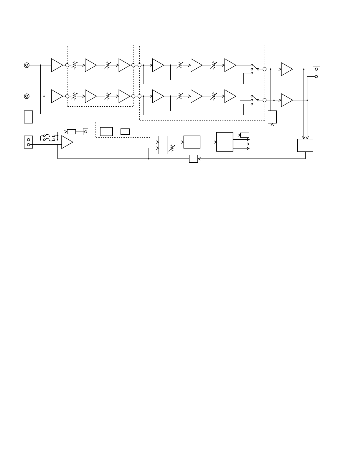
Block diagram
R-IN
L-IN
HI-INPUT
POWER
INPUT
+12V
D.C.
REM
INPUT
AMP
31
57
R
L
F01,F02
VARIABLE/INV.CIRCUIT(Gain1)/Amplifier
U101
7
-A
VR101B
U101
6
-B
VR101A
Q790
Q701
Q702
BOOST 0-12dB CROSSOVER
3
U102
-A
6
U102
-B
CCFL+12V
1
VR103A
7
VR103B
INVERTER
3
1
U106
-A
3
1
U206
-A
LOAD
2 2
1 1
3
5
CCFL
board
50-250Hz 12dB/OCT VARIABLE
1
U103
-A
U103
-B
VR102A
7
VR102B
POWER
CONTROL
U701
REGULATOR
VR701
2
U104
-A
6
U104
-B
POWER
Q730,Q731
Q745-Q747
Q755-Q757
Q705
-708
1
VR102C
7
VR102D
TRANS
& REGULATOR
2
6
T1
U703
U704
U105
-A
U105
-B
POWER
Q150
Q250
AMP
Q142-Q146
Q148,Q149
Q152
Q161-Q166
Q242-Q246
Q248,Q249
Q252
Q261-Q266
R-OUT
L-OUT
SW101A
1
LPF
HPF
OFF
7
LPF
HPF
OFF
6
SW101B
7
MUTE
CONTROL
Q780
+/-15V
VCC
VEE
PROTECT
Q171-Q176
Q272
2-1
Page 2
Caution
If electricity is connected during disassembly, it must be a no load current. If it is load
current, be sure to attach a heat sink to the power-amp IC. This will be damaged if the
above precautions are not followed, as it does not have a sub heat sink attached to it.
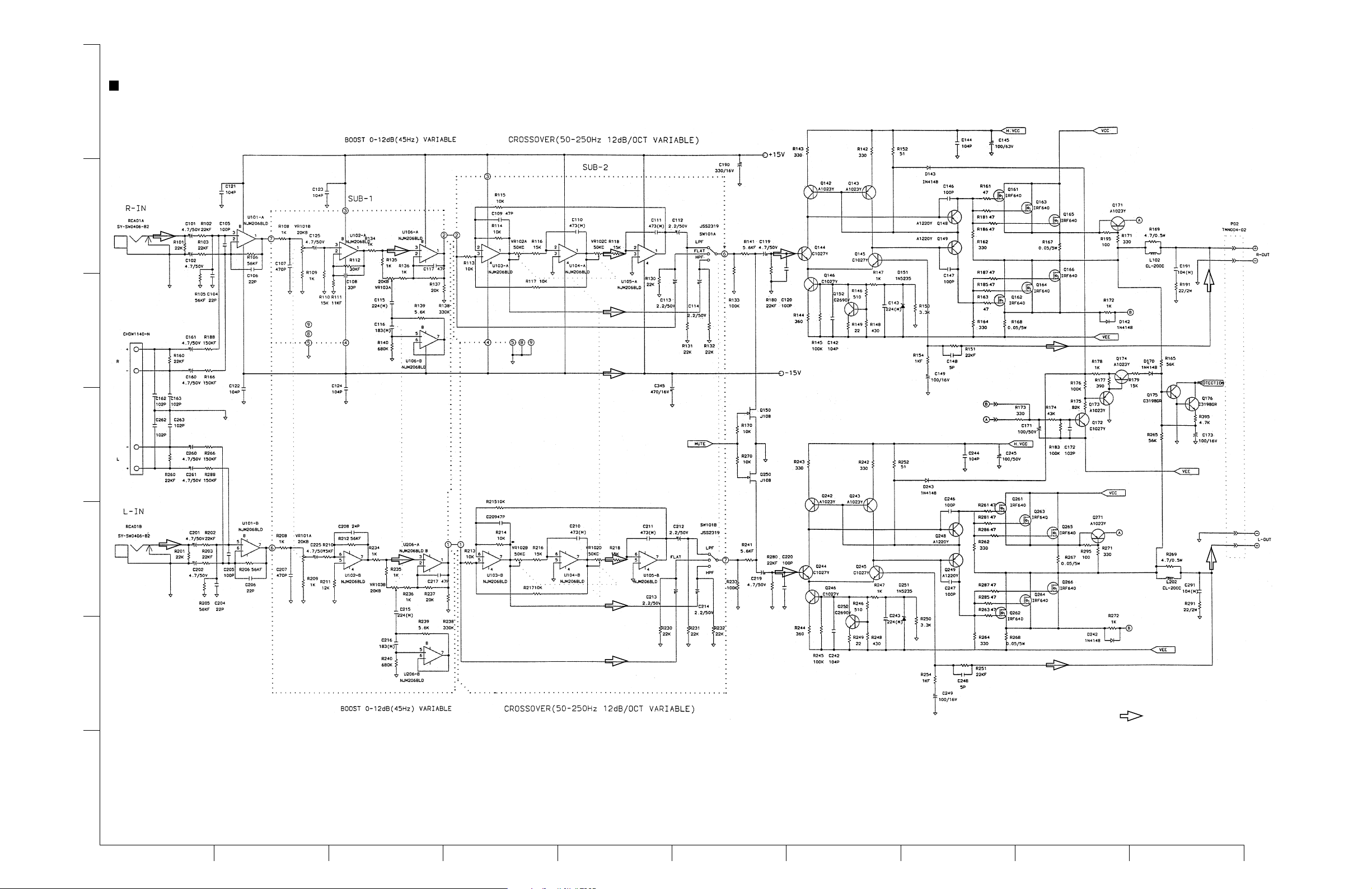
Standard schematic diagrams
Main board and sub [1/2] /sub2 board circuit diagram
7
6
5
KS-AX6700
4
3
2
SUB2 PCB
SUB1 PCB
Indicates main signal
1
BCDEFGH I JA
2-2
Page 3

KS-AX6700
Caution
If electricity is connected during disassembly, it must be a no load current. If it is load
current, be sure to attach a heat sink to the power-amp IC. This will be damaged if the
above precautions are not followed, as it does not have a sub heat sink attached to it.
Main board [2/2] and CCFL board circuit diagram
CCFL - Inverter board
7
6
CCFL PCB
5
4
3
2
Parts are safety assurance parts.
When replacing those parts make
sure to use the specified one.
1
BCDEFGH I JA
2-3
Page 4

Printed circuit boards
Main board
7
6
5
KS-AX6700
Surface side view
4
3
2
1
BCDEFGH I JA
Caution
If electricity is connected during disassembly, it must be a no load current. If it is load
current, be sure to attach a heat sink to the power-amp IC. This will be damaged if the
above precautions are not followed, as it does not have a sub heat sink attached to it.
2-4
Page 5

KS-AX6700
Caution
If electricity is connected during disassembly, it must be a no load current. If it is load
current, be sure to attach a heat sink to the power-amp IC. This will be damaged if the
above precautions are not followed, as it does not have a sub heat sink attached to it.
7
Bottom side view
6
5
4
3
2
1
BCDEFGH I JA
2-5
Page 6

KS-AX6700
Sub1/sub2 P.C. board (Volume board)
7
6
5
4
CCFL P.C. board
3
2
1
BCDEA
2-6
 Loading...