

Page 1
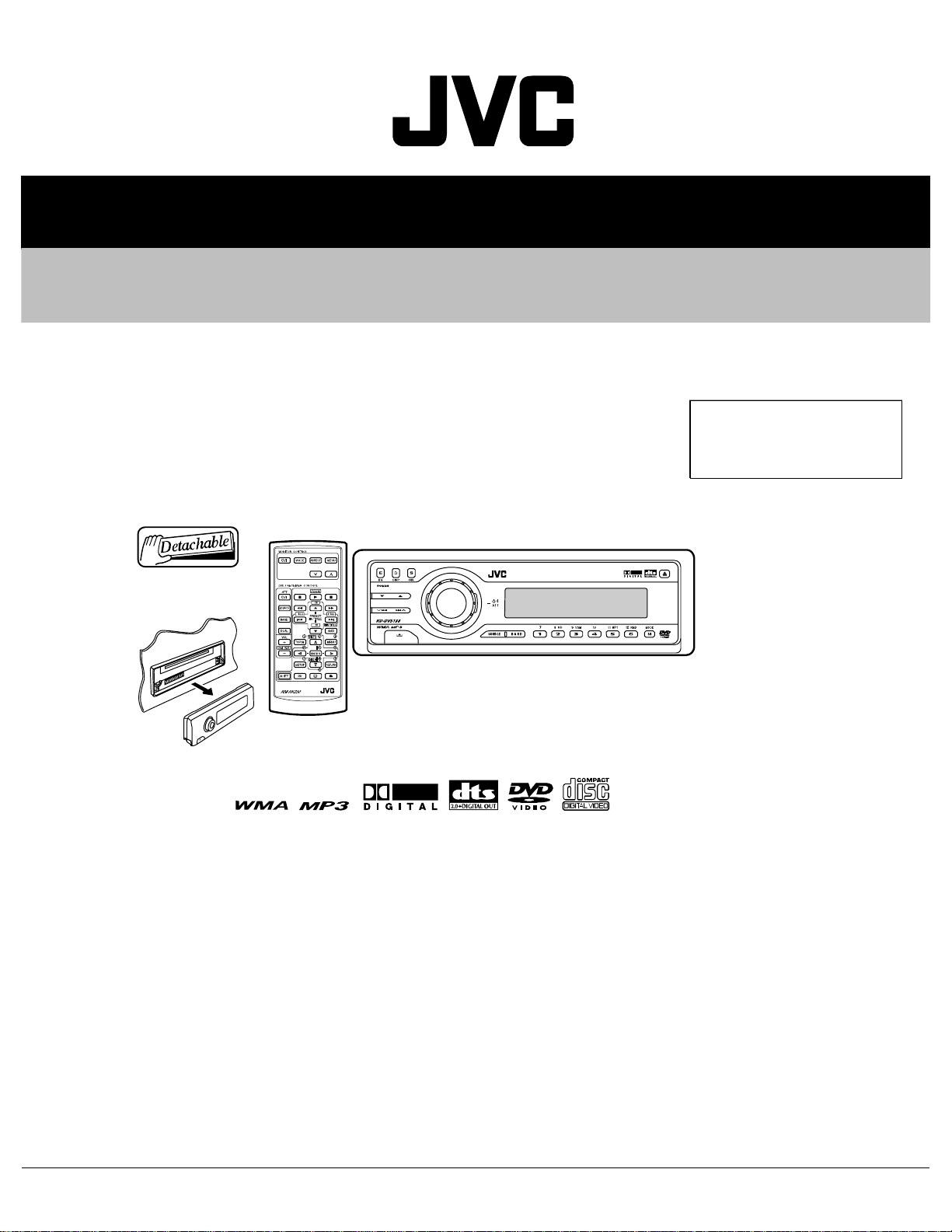
SERVICE MANUAL
DVD/CD RECEIVER
MA17320053
KD-DV5188
ß®»¿ -«ºº·¨
ЛЪ уууууууууууууууууууууууууу Э¸·²¿
TABLE OF CONTENTS
1PRECAUTIONS . . . . . . . . . . . . . . . . . . . . . . . . . . . . . . . . . . . . . . . . . . . . . . . . . . . . . . . . . . . . . . . . . . . . . . . 1-3
2SPECIFIC SERVICE INSTRUCTIONS. . . . . . . . . . . . . . . . . . . . . . . . . . . . . . . . . . . . . . . . . . . . . . . . . . . . . . 1-6
3DISASSEMBLY . . . . . . . . . . . . . . . . . . . . . . . . . . . . . . . . . . . . . . . . . . . . . . . . . . . . . . . . . . . . . . . . . . . . . . . 1-7
4ADJUSTMENT . . . . . . . . . . . . . . . . . . . . . . . . . . . . . . . . . . . . . . . . . . . . . . . . . . . . . . . . . . . . . . . . . . . . . . . 1-21
5TROUBLESHOOTING . . . . . . . . . . . . . . . . . . . . . . . . . . . . . . . . . . . . . . . . . . . . . . . . . . . . . . . . . . . . . . . . . 1-29
COPYRIGHT © 2005 Victor Company of Japan, Limited
No.MA173
2005/3
Page 2
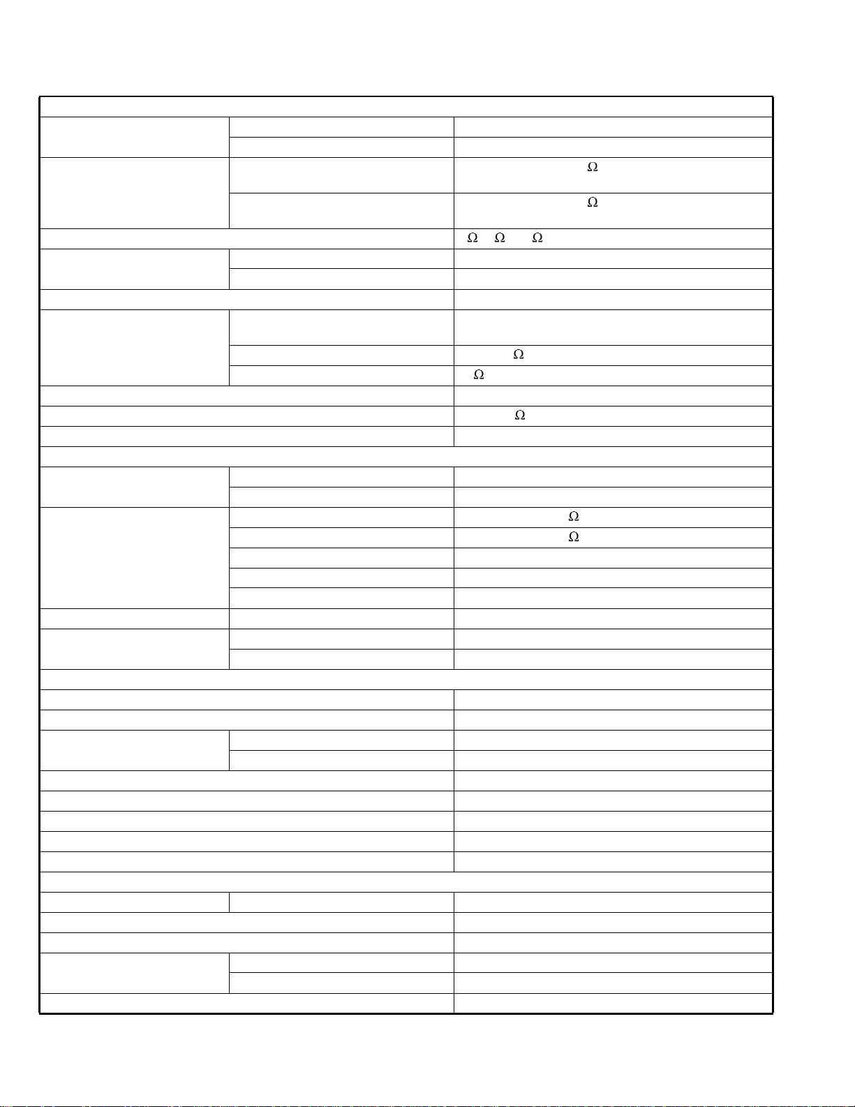
SPECIFICATION
AUDIO AMPLIFIER SECTION
Maximum Power OutputFront50 W per channel
Rear50 W per channel
Continuous Power Output (RMS)Front19 W per channel into 4 , 40 Hz to 20 000 Hz at no more
than 0.8% total harmonic distortion.
Rear19 W per channel into 4 , 40 Hz to 20 000 Hz at no more
than 0.8% total harmonic distortion.
Load Impedance4 (4 to 8 allowance)
Equalizer Control RangeFrequencies60 Hz, 150 Hz, 400 Hz, 1 kHz, 2.4 kHz, 6 kHz, 15 kHz
Level±10 dB
Signal-to-Noise Ratio70 dB
Audio Output LevelDigital (DIGITAL OUT: Optical)Signal wave length : 660 nm
Output level : -21 dBm to -15 dBm
Line-Out Level/Impedance2.5 V/20 k load (full scale)
Output Impedance1 k
Color SystemPAL/NTSC
Video Output (composite)1 Vp-p/75
Other TerminalsLINE IN, CD changer
TUNER SECTION
Frequency RangeFM87.5 MHz to 108.0 MHz
AM531 kHz to 1 602 kHz
FM TunerUsable Sensitivity11.3 dBf (1.0 kV/75 )
50 dB Quieting Sensitivity16.3 dBf (1.8 kV/75 )
Alternate Channel Selectivity (400 kHz)65 dB
Frequency Response40 Hz to 15 000 Hz
Stereo Separation35 dB
Capture Ratio1.5 dB
AM TunerSensitivity20 kV
Selectivity35 dB
DVD/CD PLAYER SECTION
Signal Detection SystemNon-contact optical pickup (semiconductor laser)
Number of Channels2 channels (stereo)
Frequency ResponseDVD, fs=48 kHz/96 kHz16 Hz to 22 000 Hz
VCD, CD, MP3, WMA16 Hz to 20 000 Hz
Dynamic Range96 dB
Signal-to-Noise Ratio98 dB
Wow and FlutterLess than measurable limit
MP3 (MPEG Audio Layer 3)Max. Bit Rate: 320 kbps
WMA (Windows Media Audio)Max. Bit Rate: 192 kbps
GENERAL
Power RequirementOperating VoltageDC 14.4 V (11 V to 16 V allowance)
Grounding SystemNegative ground
Allowable Operating Temperature0pC to +40pC
Dimensions (W I H I D)Installation Size (approx.)182 mm I 52 mm I 158 mm
Panel Size (approx.)188 mm I 58 mm I 11 mm
Mass (approx.)1.7 kg (excluding accessories)
Design and specifications are subject to change without notice.
1-2 (No.MA173)
Page 3
1.1Safety Precautions
SECTION 1
PRECAUTIONS
ÿ
ÿ
Þ«®®- º±®³»¼ ¼«®·²¹ ³±´¼·²¹ ³¿§ ¾» ´»º¬ ±ª»® ±² -±³» °¿®¬- ±º ¬¸» ½¸¿--·-ò ̸»®»º±®»ô
°¿§ ¿¬¬»²¬·±² ¬± -«½¸ ¾«®®- ·² ¬¸» ½¿-» ±º °®»º±®³·²¹ ®»°¿·® ±º ¬¸·- -§-¬»³ò
д»¿-» «-» »²±«¹¸ ½¿«¬·±² ²±¬ ¬± -»» ¬¸» ¾»¿³ ¼·®»½¬´§ ±® ¬±«½¸ ·¬ ·² ½¿-» ±º ¿²
¿¼¶«-¬³»²¬ ±® ±°»®¿¬·±² ½¸»½µò
(No.MA173)1-3
Page 4
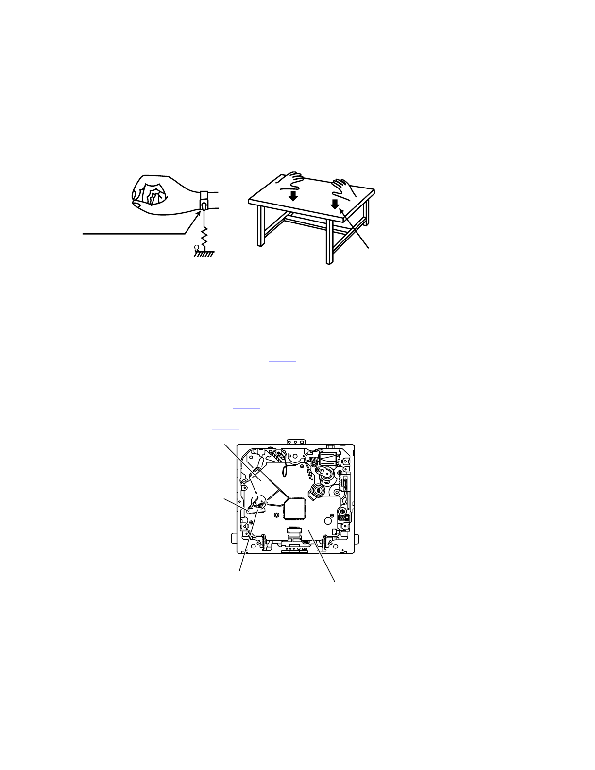
1.2Preventing static electricity
Electrostatic discharge (ESD), which occurs when static electricity stored in the body, fabric, etc. is discharged, can destroy the laser
diode in the traverse unit (optical pickup). Take care to prevent this when performing repairs.
1.2.1 Grounding to prevent damage by static electricity
Static electricity in the work area can destroy the optical pickup (laser diode) in devices such as CD players.
Be careful to use proper grounding in the area where repairs are being performed.
(1)Ground the workbench
Ground the workbench by laying conductive material (such as a conductive sheet) or an iron plate over it before placing the
traverse unit (optical pickup) on it.
(2)Ground yourself
Use an anti-static wrist strap to release any static electricity built up in your body.
ø½¿°¬·±²÷
ß²¬·ó-¬¿¬·½ ©®·-¬ -¬®¿°
ïÓ
ݱ²¼«½¬·ª» ³¿¬»®·¿´
ø½±²¼«½¬·ª» -¸»»¬÷ ±® ·®±² °´¿¬»
(3)Handling the optical pickup
In order to maintain quality during transport and before installation, both sides of the laser diode on the replacement optical
pickup are shorted. After replacement, return the shorted parts to their original condition.
(Refer to the text.)
Do not use a tester to check the condition of the laser diode in the optical pickup. The tester's internal power source can easily
destroy the laser diode.
1.3Handling the traverse unit (optical pickup)
(1)Before disconnecting the flexible wire from the connector CN101 on the mechanism control board, solder the short-circuit points
on the flexible wire.
Caution:
If you do not follow this instruction, the DVD pickup may be damaged.
(2)Disconnect the flexible wire from the connector CN101 on the mechanism control board.
(3)Remove the solders from the short-circuit points on the flexible wire after replacing the DVD pickup.
(4)Connect the flexible wire to the connector CN101 on the mechanism control board.
Ú´»¨·¾´» ©·®»
ЭТпрп
1-4 (No.MA173)
͸±®¬ó½·®½«·¬ °±·²¬-
Ó»½¸¿²·-³ ½±²¬®±´ ¾±¿®¼
Page 5
1.4Important for laser products
птЭФЯНН п ФЯНЫО РОСЬЛЭМ
отЬЯТЩЫО ж ײª·-·¾´» ´¿-»® ®¿¼·¿¬·±² ©¸»² ±°»² ¿²¼ ·²¬»®
´±½µ º¿·´»¼ ±® ¼»º»¿¬»¼ò ߪ±·¼ ¼·®»½¬ »¨°±-«®» ¬± ¾»¿³ò
нтЭЯЛМЧСТ ж ̸»®» ¿®» ²± -»®ª·½»¿¾´» °¿®¬- ·²-·¼» ¬¸»
Ô¿-»® ˲·¬ò ܱ ²±¬ ¼·-¿--»³¾´» ¬¸» Ô¿-»® ˲·¬ò λ°´¿½»
¬¸» ½±³°´»¬» Ô¿-»® ˲·¬ ·º ·¬ ³¿´º«²½¬·±²-ò
мтЭЯЛМЧСТ ж М¸» ЭЬфУЬ ¿²¼ ЬКЬ °´¿§»® «-»- ·²ª·-·¾´»
´¿-»® ®¿¼·¿¬·±² ¿²¼ ·- »¯«·°°»¼ ©·¬¸ -¿º»¬§ -©·¬½¸»- ©¸·½¸
°®»ª»²¬ »³·--·±² ±º ®¿¼·¿¬·±² ©¸»² ¬¸» ¼®¿©»® ·- ±°»² ¿²¼
¬¸» -¿º»¬§ ·²¬»®´±½µ- ¸¿ª» º¿·´»¼ ±® ¿®» ¼»º»¿¬»¼ò ׬ ·-
¼¿²¹»®±«- ¬± ¼»º»¿¬ ¬¸» -¿º»¬§ -©·¬½¸»-ò
лтЭЯЛМЧСТ ж ׺ -¿º»¬§ -©·¬½¸»- ³¿´º«²½¬·±²ô ¬¸» ´¿-»® ·- ¿¾´»
¬± º«²½¬·±²ò
ктЭЯЛМЧСТ ж Ë-» ±º ½±²¬®±´-ô ¿¼¶«-¬³»²¬- ±® °»®º±®³¿²½» ±º
°®±½»¼«®»- ±¬¸»® ¬¸¿² ¬¸±-» -°»½·º·»¼ ¸»®» ·² ³¿§ ®»-«´¬ ·²
¸¿¦¿®¼±«- ®¿¼·¿¬·±² »¨°±-«®»ò
д»¿-» «-» »²±«¹¸ ½¿«¬·±² ²±¬ ¬±
-»» ¬¸» ¾»¿³ ¼·®»½¬´§ ±® ¬±«½¸ ·¬
·² ½¿-» ±º ¿² ¿¼¶«-¬³»²¬ ±® ±°»®¿¬·±²
½¸»½µò
ОЫРОСЬЛЭМЧСТ ЯТЬ РСНЧМЧСТ СЪ ФЯЮЫФН
ЙЯОТЧТЩ ФЯЮЫФ
ЭЯЛМЧСТ æ Ê·-·¾´» ¿²¼ ײª·-·¾´»
ЭФЯНН п
ФЯНЫО РОСЬЛЭМ
´¿-»® ®¿¼·¿¬·±² ©¸»² ±°»² ¿²¼
·²¬»®´±½µ º¿·´»¼ ±® ¼»º»¿¬»¼т
ЯКСЧЬ ЬЧОЫЭМ ЫИРСНЛОЫ МС
ЮЫЯУт ш»ч
ЯЬКЯОНЫФ æ ͧ²´·¹ ±¹ «-§²´·¹
´¿-»®-¬®;´·²¹ ²;® ³¿-µ·²»² »®
;¾»² »´´»® ·²¬»®´±½µ»² º»¶»´»®ò
˲¼¹; ¼·®»µ¬» »µ-°±²»®·²¹ ¬·´
-¬®;´·²¹ò ø¼÷
КЯОТЧТЩ æ ͧ²´·¹ ±½¸
±-§²´·²¹ ´¿-»®-¬®;´²·²¹ ²<®
¼»² *°°²¿- ±½¸ -°<®®»² <®
«®µ±°°´¿¼ò Þ»¬®¿µ¬¿ »¶
-¬®;´»²ò ø-÷
ÊßÎÑ æ ߪ¿¬¬¿»--¿ ¶¿ -«±¶¿´«µ·¬«±¸·¬»¬¬«²¿ ¬¿· ª·¿´´·-»²¿ ±´»¬ ¿´¬¬··²¿
²<µ§ª<´´» ¶¿ ²<µ§³<¬¬*³<´´»
´¿-»®-<¬»·´§´´»ò Ê<´¬< -<¬»»²
µ±¸¼·-¬«³·-¬¿ -«±®¿¿² ·¬-»»-·ò øº÷
(No.MA173)1-5
Page 6

SECTION 2
SPECIFIC SERVICE INSTRUCTIONS
This service manual does not describe SPECIFIC SERVICE INSTRUCTIONS.
1-6 (No.MA173)
Page 7
SECTION 3
DISASSEMBLY
3.1Main body section
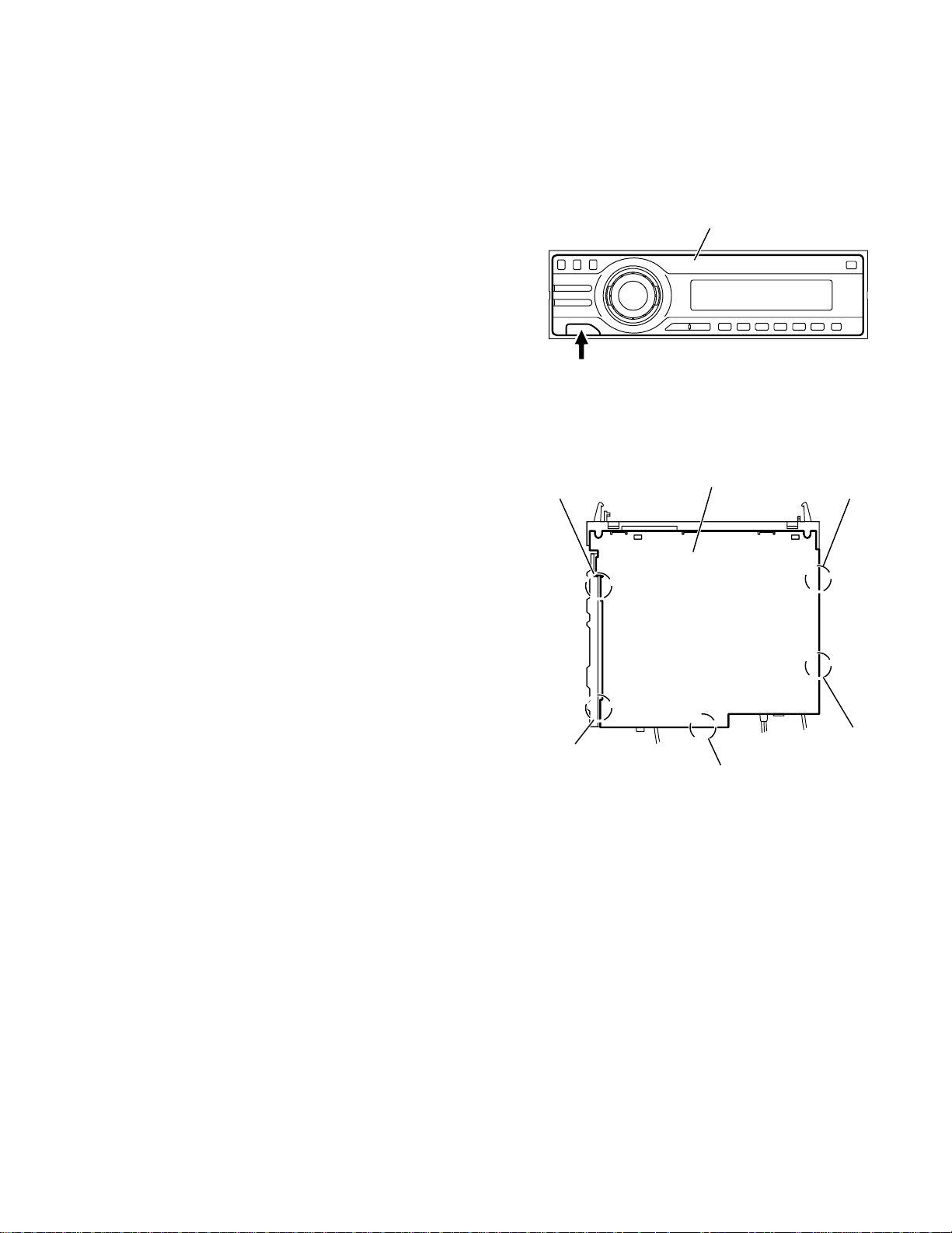
3.1.1Removing the front panel assembly
(See Fig.1)
Push the detach button in the lower left part of the front panel assembly and remove the front panel assembly.
3.1.2Removing the bottom cover
(See Fig.2)
Reference:
Remove the front panel assembly as required.
(1)Release the two joints a, two joints b and joint c.
(2)Remove the bottom cover from the main body.
Caution:
Do not damage the main board when releasing the joints using
a screwdriver or a similar tool.
Ú®±²¬ °¿²»´ ¿--»³¾´§
Ü»¬¿½¸ ¾«¬¬±²
¾
Fig.1
Þ±¬¬±³ ½±ª»®
¿
¿
¾
½
Fig.2
(No.MA173)1-7
Page 8
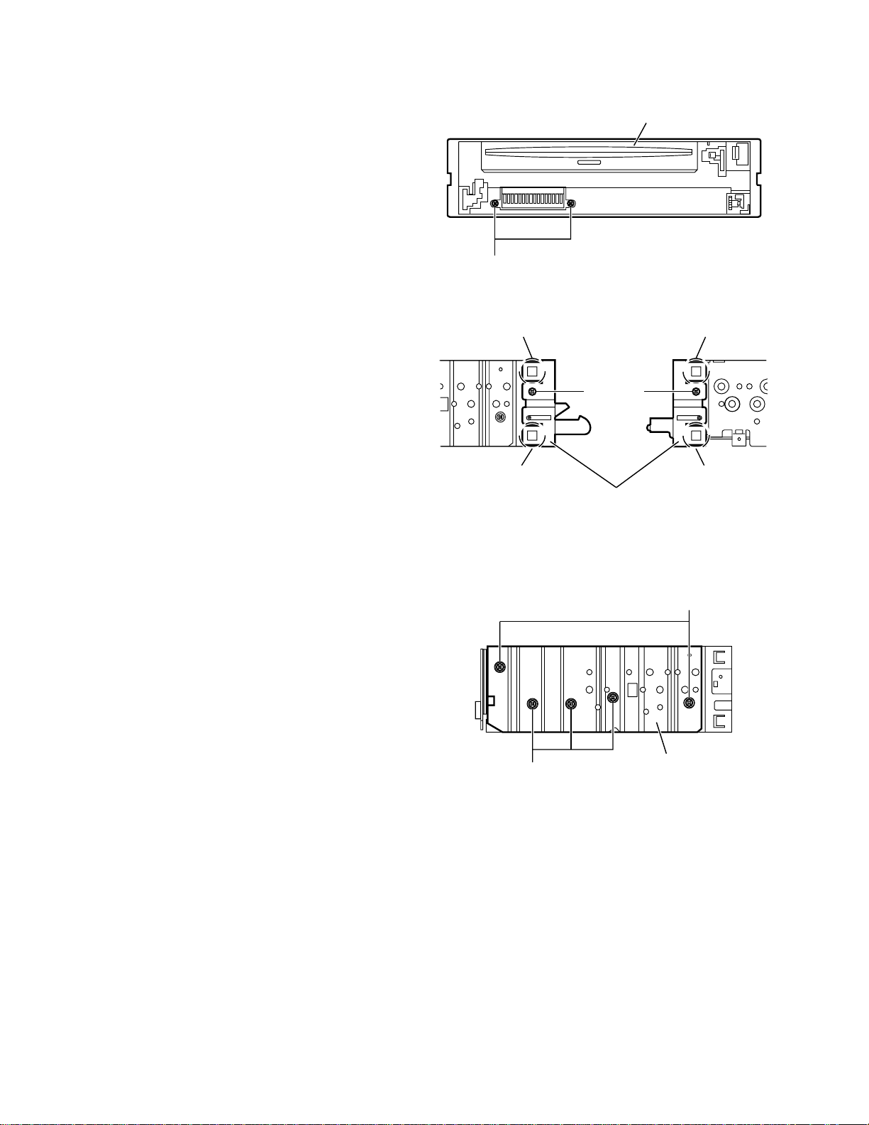
3.1.3Removing the front chassis assembly
(See Figs.3 and 4)
Remove the front panel assembly and bottom cover.
(1)From the front side of the main body, remove the two
screws A attaching the front chassis assembly. (See
Fig.3.)
(2)From the both sides of the main body, remove the two
screws B attaching the front chassis assembly. (See
Fig.4.)
(3)Release the two joints d and two joints e. (See Fig.4.)
Ú®±²¬ ½¸¿--·- ¿--»³¾´§
ß
Fig.3
3.1.4Removing the side heat sink
(See Fig.5)
Reference:
Remove the front panel and front chassis assemblies as re-
quired.
From the left side of the main body, remove the two screws C and
three screws D attaching the side heat sink.
¼
Þ
¼
Ú®±²¬ ½¸¿--·- ¿--»³¾´§
Fig.4
»
Þ
»
Ý
1-8 (No.MA173)
Ü
Í·¼» ¸»¿¬ -·²µ
Fig.5
Page 9
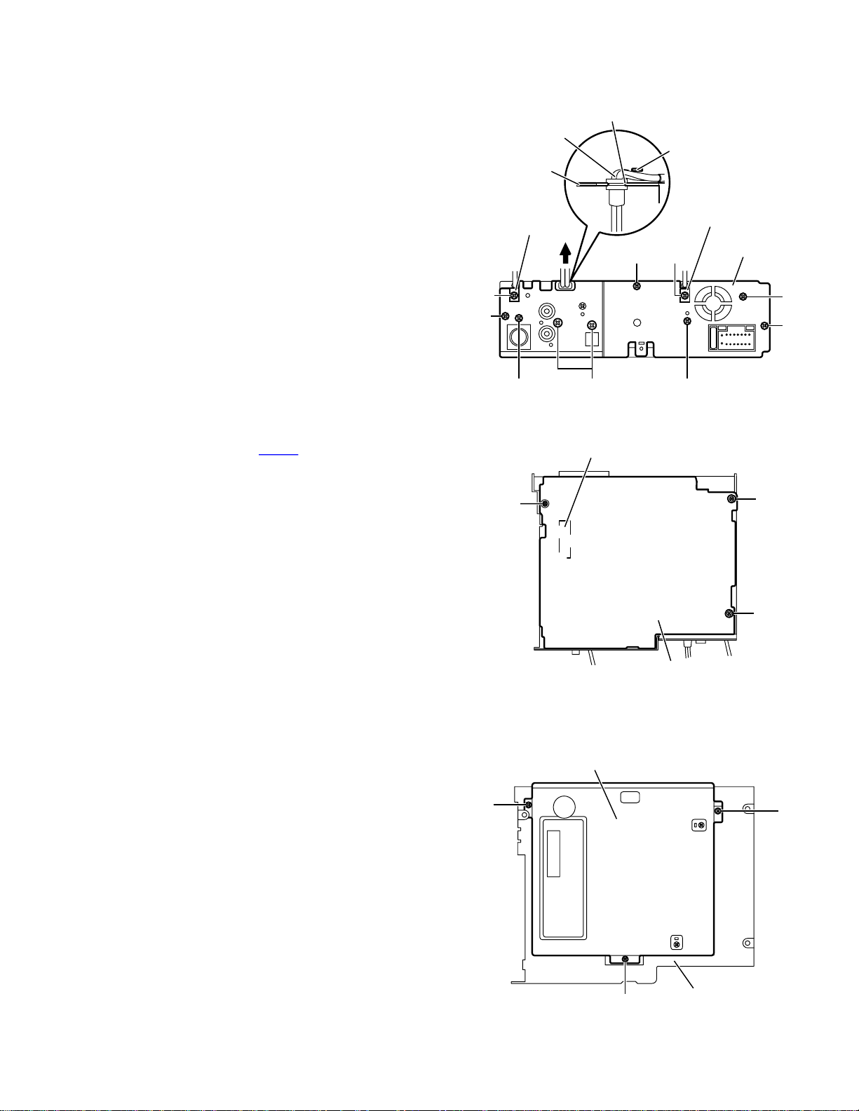
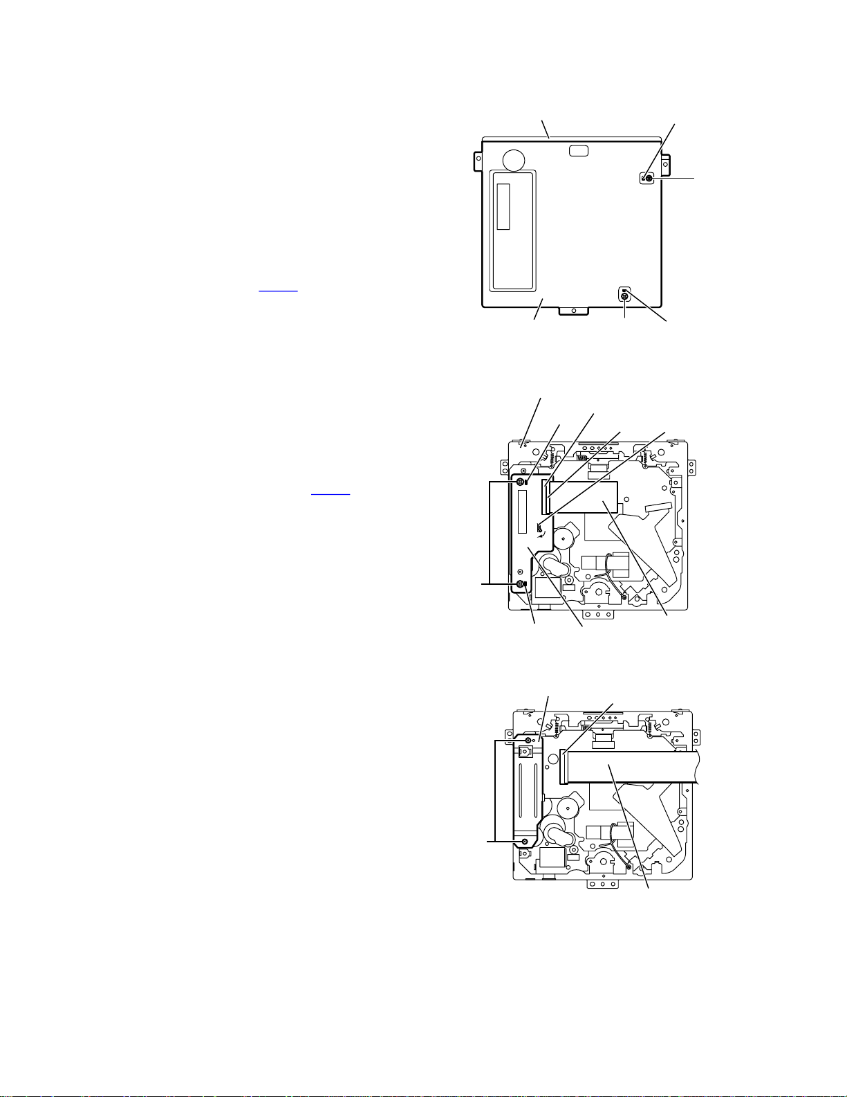
3.1.5Removing the rear bracket
(See Fig.6)
Remove the bottom cover.
(1)From the back side of the main body, remove the two
screws E, two screws E', screw F, two screws G and three
screws H attaching the rear bracket.
(2)Remove the LINE IN cable from the rear bracket in the di-
rection of the arrow.
Reference:
When attaching the LINE IN cable, insert it in a slot of the
rear bracket and hang it on a wire holder.
When attaching the screws E', attach the cable holders with
them.
Ô×ÒÛ ×Ò ½¿¾´»
λ¿® ¾®¿½µ»¬
Ý¿¾´» ¸±´¼»®
Í´±¬
É·®» ¸±´¼»®
ØÛÛù
Ý¿¾´» ¸±´¼»®
λ¿® ¾®¿½µ»¬
3.1.6Removing the main board
(See Figs.6 and 7)
Remove the front panel assembly, bottom cover, front chassis
assembly and side heat sink.
Reference:
Remove the rear bracket as required.
(1)From the back side of the main body, remove the three
screws H attaching the main board. (See Fig.6.)
(2)From the bottom side of the main body, remove the three
screws J attaching the main board. (See Fig.7.)
(3)Disconnect the connector CN961 on the main board from
the DVD mechanism assembly and take out the main
board from the main body. (See Fig.7.)
3.1.7Removing the DVD mechanism assembly
(See Fig.8)
Remove the front panel assembly, bottom cover, front chassis
assembly, side heat sink and main board.
(1)From the inside of the top chassis, remove the three
screws K attaching the DVD mechanism assembly.
(2)Take out the DVD mechanism assembly from the top cha
sis.
Ûù
Ø
Õ
Ú
Ù
Fig.6
ЭТзкп
Ö
Fig.7
ÜÊÜ ³»½¸¿²·-³ ¿--»³¾´§
Û
Ø
Ö
Ö
Ó¿·² ¾±¿®¼
Õ
Õ
Fig.8
̱° ½¸¿--·-
(No.MA173)1-9
Page 10
3.1.8Removing the main sub board
(See Figs.9 to 11)
Remove the front panel assembly, bottom cover, front chassis
assembly, side heat sink, main board and DVD mechanism assembly.
(1)From the top side of the DVD mechanism assembly, re-
move the two screws L attaching the dust cover. (See
Fig.9.)
(2)Remove the dust cover from the DVD mechanism assem-
bly. (See Fig.9.)
Reference:
When attaching the dust cover, align the joints f in the
holes of the dust cover before attaching the screws L.
(See Fig.9.)
(3)Release the lock of the connector CN962 on the main sub
board and disconnect the card wire. (See Fig.10.)
(4)Bend the joint g in the direction of the arrow. (See Fig.10.)
(5)Remove the two screws M attaching the main sub board
and remove the main sub board from the DVD mechanism
assembly. (See Fig.10.)
Reference:
When attaching the main sub board, align the joints h in the
holes of the main sub board before attaching the screws M.
(See Fig.10.)
When the resolution of DVD mechanism assembly is done
sequentially, remove the two screws N attaching the support
bracket. (See Fig.11.)
Remove the card wire from the connector CN401 as re-
quired. (See Fig.11.)
ÜÊÜ ³»½¸¿²·-³ ¿--»³¾´§
Ü«-¬ ½±ª»®
Fig.9
ÜÊÜ ³»½¸¿²·-³ ¿--»³¾´§
¸
ЭТзко
Ô±½µ
Ô
º
Ô
º
¹
Ó
Í«°°±®¬ ¾®¿½µ»¬
Ò
¸
Ó¿·² -«¾ ¾±¿®¼
Fig.10
Fig.11
Ý¿®¼ ©·®»
ЭТмрп
Ý¿®¼ ©·®»
1-10 (No.MA173)
Page 11

3.1.9Removing the switch board
(See Figs. 12 to 14)
Remove the front panel assembly.
(1)From the back side of the front panel assembly, remove the
five screws P attaching the rear cover. (See Fig.12.)
(2)Release the ten joints i attaching the rear cover to the front
panel assembly. (See Fig.13.)
(3)Take out the switch board while lifting the switch board
from the front panel assembly little by little. (See Fig.14.)
Reference:
Remove the volume knob from the front side of the front panel
assembly at the same time.
Note:
Do not lose the compression springs when removing the
switch board. (See Fig.14.)
λ¿® ½±ª»®
Ð
Ú®±²¬ °¿²»´ ¿--»³¾´§
Ð
Ð
Fig.12
·
·
λ¿® ½±ª»®
Í©·¬½¸ ¾±¿®¼
ݱ³°®»--·±² -°®·²¹
·
·
Fig.13
Ú®±²¬ °¿²»´ ¿--»³¾´§
ݱ³°®»--·±² -°®·²¹
Fig.14
(No.MA173)1-11
Page 12
3.2DVD mechanism assembly
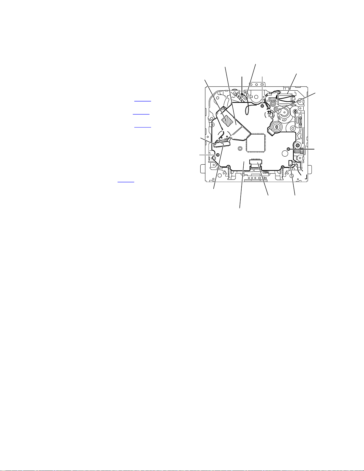
3.2.1Removing the mechanism control board
(See Fig.1)
Caution:
Before disconnecting the flexible wire extending from the DVD
pickup, solder the short-circuit point on the flexible wire using
a grounding soldering iron. If you do not follow this instruction,
the DVD pickup may be damaged.
(1)Turn over the body, and solder the short-circuit points on
the flexible wire extending from the DVD pickup.
(2)Disconnect the flexible wire from connector CN101
mechanism control board.
(3)Disconnect the card wire from connector CN201 on the
mechanism control board.
(4)Disconnect the flexible wire from connector CN202 on the
mechanism control board.
(5)Unsolder two soldered points a on the mechanism control
board and remove the wire extending from the feed motor.
(6)Remove the screw A attaching the lug wire.
(7)Remove the two screws B and screw C attaching the
mechanism control board.
Caution:
As the flexible wire to be connected to CN101, make sure to
attach it to the mechanism control board using a double
tape.
After reassembling, unsolder the short-circuit points.
on the
Ú´»¨·¾´» ©·®»
ܱ«¾´» ¬¿°»
ЭТпрп
Ô«¹ ©·®»
ß
Þ
͸±®¬ó½·®½«·¬ °±·²¬-
Þ
ЭТорп
Ú»»¼ ³±¬±®
¿
Ý
ЭТоро
Ó»½¸¿²·-³ ½±²¬®±´ ¾±¿®¼
Fig.1
1-12 (No.MA173)
Page 13

3.2.2Removing the top cover
(See Fig.2)
(1)Remove the two screws D attaching the top cover on the
back of the body.
(2)Remove the top cover upward.
Reference:
When reassembling, set part b of the top cover under the
bending part c of the chassis frame.
3.2.3Removing the mechanism section
(See Fig.2 to 4)
Remove the top cover.
(1)From the bottom of the body, remove the screw E attaching
the lug wire. (See Fig.2.)
(2)Remove the two screws F attaching the right and left stop-
pers on the front side. (See Fig.2.)
(3)Remove the two floating springs on the bottom of the body.
(See Fig.3.)
(4)Move the mechanism section upward and remove from the
chassis frame.
The three damper springs come off from the dampers.
(See Fig.4.)
Caution:
When reassembling, reattach the damper spring to the
damper respectively and insert the three shafts on the bottom of the mechanism to the dampers.
Before inserting the shaft to the dampers, apply IPA to the
hole of damper.
Ú´±¿¬·²¹ -°®·²¹
Fig.3
Ó»½¸¿²·-³ -»½¬·±²
ͬ±°°»®
Ú
̱° ½±ª»®
ͬ±°°»®
Ú
Ü
Ü
¾
½
Û
Ô«¹ ©·®»
Ь¿³°»® НРтшЪч
øÍ·´ª»®÷
Ü¿³°»® øÚ÷
øÞ´¿½µ÷
Ь¿³°»® НРтшЪч
øÍ·´ª»®÷
Ü¿³°»® øÚ÷
øÞ´¿½µ÷
Fig.4
Ь¿³°»® НРтшОч
øλ¼÷
Ü¿³°»® øÎ÷
øЫ®°´»÷
ݸ¿--·- º®¿³»
Fig.2
(No.MA173)1-13
Page 14

3.2.4Removing the clamper unit
(See Fig.5 to 7)
Remove the top cover and the mechanism section.
(1)Remove the clamper2 spring on the bottom of the mecha-
nism section. (See Figs.5.and 6.)
(2)Release the part d of the clamper spring from the bending
part of the chassis base assembly. (See Fig.7.)
(3)Move the clamper unit in the direction of the arrow and turn.
Release the two joints e and f, then remove the clamper
unit upward. (See Fig.6.)
3.2.5Reattaching the clamper unit
(See Fig.5 to 9)
(1)Attach the clamper spring to the clamper unit. (See Fig.8.)
(2)Move the clamper unit to set the side joints e and f to each
boss of the chassis base assembly. Make sure that part g
is inserted to the notch of the chassis base assembly. (See
Figs.5 and 9.)
(3)Move the part d of the clamper spring to the outside of the
bending part of the chassis base assembly. (See Fig.7.)
(4)Attach the clamper2 spring to the chassis base assembly.
(See Figs.5 and 6.)
Caution:
When reattaching, temporarily hook the end of the clamper
spring as shown in the figure to make the work easy. (See
Fig.8.)
Ý´¿³°»® «²·¬
Ý´¿³°»®î -°®·²¹
ݸ¿--·- ¾¿-» ¿--»³¾´§
Fig.6
Ý´¿³°»® -°®·²¹
Ý´¿³°»® -°®·²¹
º
Ý´¿³°»®î -°®·²¹
ݸ¿--·- ¾¿-» ¿--»³¾´§
¹
¼
ݸ¿--·- ¾¿-» ¿--»³¾´§
Fig.7
»
Fig.5
1-14 (No.MA173)
Page 15

Ý´¿³°»® «²·¬
Ý´¿³°»® -°®·²¹
Ý´¿³°»® «²·¬
Fig.8
Fig.9
¹
Ò±¬½¸
(No.MA173)1-15
Page 16

3.2.6Removing the front unit
(See Fig.10 to 12)
Remove the top cover and the mechanism section.
(1)Disconnect the flexible wire from connector CN202 on the
mechanism control board at the bottom of the body. (See
Fig.10.)
(2)Remove the screw G attaching the front unit on the top of
the body. (See Fig.11.)
(3)Move the front unit toward the front to release joint h, and
release two joints i and j on the right side of the chassis
base assembly. Then remove the front unit upward. (See
Figs.11 and 12.)
(4)Remove the two screws H attaching the switch board. (See
Fig.12.)
Reference:
You can remove the switch board only without removing the
front unit.
Caution:
When reassembling, attach the flexible wire extending from
the switch board using the double tape. (See Figs.10 and 12.)
Ó»½¸¿²·-³ ½±²¬®±´ ¾±¿®¼
Ù
Ú®±²¬ «²·¬
¸
Fig.11
ЭТоро
ܱ«¾´» ¬¿°»
Fig.10
Ú´»¨·¾´» ©·®»
ܱ«¾´» ¬¿°»
¶
·
Ø
Í©·¬½¸ ¾±¿®¼
Ú®±²¬ «²·¬
Ù
1-16 (No.MA173)
¸
Fig.12
Page 17

3.2.7Removing the loading arm assembly
(See Fig.13 , 14)
Remove the top cover, the mechanism section and the front
unit.
(1)From the top of the body, move the loading arm assembly
from the front side upward, and release the bosses from
the right and left joints k and m of the chassis base assembly.
(2)Release the boss from notch n of the connect arm on the
right side of the body, and release the boss from notch p of
the slide cam assembly on the left side.
³
Ô±¿¼·²¹ ¿®³ ¿--»³¾´§
Í·¼» ½¿³
¿--»³¾´§
°
³
µ
Fig.13
Ô±¿¼·²¹ ¿®³ ¿--»³¾´§
µ
²
²
ݱ²²»½¬ ¿®³
Fig.14
(No.MA173)1-17
Page 18

3.2.8Removing the rod (L)(R)/roller assembly
(See Fig.15 and 16)
Remove the top cover, the mechanism section, the front unit
and the loading arm assembly.
(1)Release the rod (L) and (R) from the joints q at the bottom
of the loading arm assembly (See Fig.15.)
(2)Remove the roller assembly from the loading arm assem-
bly. (See Fig.16.)
(3)Remove the two collars and washer from the roller assem-
bly. (See Fig.16.)
Caution:
After attaching the loading arm assembly to the roller assembly, attach the rod (L) and (R). Attach the rods to the right and
left collars of the roller. (See Fig.15.)
When reattaching the rod (L) and (R) to the loading arm assembly, engage each joint as shown in Fig.15. As joints q of
the rod (L), let the rod through q before reattaching it.
ݱ´´¿®
α¼øÎ÷ α¼øÔ÷
¯
ݱ´´¿®
¯
¯
ݱ´´¿®
α¼øÔ÷
α¼øÎ÷
¯
Ô±¿¼·²¹ ¿®³ ¿--»³¾´§
Fig.15
α´´»® ¿--»³¾´§
Ô±¿¼·²¹ ¿®³ ¿--»³¾´§
¯
α¼øÔ÷
¯
ݱ´´¿®
É¿-¸»®
α¼øÎ÷
1-18 (No.MA173)
Fig.16
Page 19

3.2.9Removing the DVD pickup assembly
(See Fig.17 to 19)
Remove the mechanism control board.
(1)From the bottom of the body, turn the feed gear in the di-
rection of the arrow to move the DVD pickup outwards.
(See Fig.17.)
(2)Remove the screw J attaching the thrust spring. (See
Fig.17.)
(3)Remove the DVD pickup assembly upward on the L.S.gear
side and release from sub shaft at joint r. Move the lead
screw of the DVD pickup assembly in the direction of the
arrow to release from joint s. (See Fig.18.)
Caution:
When releasing the lead screw at joint s, the L.S.collar
comes off at the end of the lead screw. When reassembling, reattach the L.S.collar to the lead screw and
engage joint s. (See Fig.18.)
When reattaching the L.S.collar, reattach it to the point
s of the lead screw, and to the rod (M). Make sure that
the L.S.collar is set on the rod (M) spring. (See Fig.18.)
(4)Remove the screw K attaching the rack spring/ rack plate
on the DVD pickup. (See Fig.19.)
(5)Pull out the lead screw. (See Fig.19.)
Caution:
Perform adjustment after replacing the pickup.
ÜÊÜ Ð·½µ«° ¿--»³¾´§
ÜÊÜ Ð·½µ«° ¿--»³¾´§
Ú»»¼ ¹»¿®
Ö
̸®«-¬ -°®·²¹
Fig.17
-
ÔòÍò½±´´¿®
α¼øÓ÷
Ô»¿¼ -½®»©
Í«¾ -¸¿º¬
ÔòÍò½±´´¿®
®
ÔòÍò¹»¿®
Fig.18
Õ
ο½µ -°®·²¹
Ô»¿¼ -½®»©
ο½µ °´¿¬»
ÜÊÜ Ð·½µ«°
Fig.19
(No.MA173)1-19
Page 20

3.2.10Removing the spindle motor
®
(See Fig.20)
Remove the mechanism control board.
Remove the two screws L attaching the spindle motor on the
bottom of the body.
Caution:
Perform adjustment when reattaching the spindle motor.
3.2.11Removing the feed motor assembly
(See Fig.21 and 22)
Remove the mechanism control board.
(1)Remove the feed TRI. spring on the bottom of the body.
(See Fig.21.)
(2)Remove the two screws M attaching the feed motor as-
sembly. (See Fig.21.)
(3)Remove the slit washer from the motor H. assembly and
pull out the worm wheel. (See Fig.22.)
Remove the two screws N attaching the feed motor. (See
Fig.22.)
Í°·²¼´» ³±¬±®
Ô
Fig.20
Ú»»¼ ÌÎ×ò -°®·²¹
Ó
Ú»»¼ ³±¬±® ¿--»³¾´§
1-20 (No.MA173)
Í´·¬ ©¿-¸»®
ɱ®³ ©¸»»´
Ò
Ó±¬±® Øò ¿--»³¾´§
Fig.21
Ú»»¼ ³±¬±
Fig.22
Page 21

SECTION 4
ADJUSTMENT
4.1Test instruments required for adjustment
(1)Digital oscilloscope (100MHz)
(2)Jitter meter
(3)Digital tester
(4)Electric voltmeter
(5)Tracking offset meter
(6)Test Disc : VT501 or VT502
(7)Extension studs : STDV001-3P
(8)Extension cable : EXTDV002-30P
4.3Connection method
Connection procedure
(1)Attach the front chassis assembly to the main board.
(2)Connect the front panel assembly to the main board.
(3)Attach the heat sink and rear bracket to the main board.
(4)Attach the extension studs to the DVD mechanism assembly.
(5)Connect the DVD mechanism assembly and the main board with a extension cable.
4.2Standard measuring conditions
Power supply voltageDC14.4V(11 to 16V)
Load impedance4(2 Speakers connection)
Line Output20K
Caution:
Be sure to attach the heat sink and rear bracket onto the power
amplifier IC and regulator IC respectively, before supply the
power. If voltage is applied without attaching these parts, the
power amplifier IC and regulator IC will be destroyed by heat.
Ы¨¬»²-·±² ½¿¾´»
ЫИМЬКрроунрР
Ø»¿¬ -·²µ
λ¿® ¾®¿½µ»¬
Ó¿·² ¾±¿®¼
Ы¨¬»²-·±² -¬«¼
НМЬКррпунР
Ы¨¬»²-·±² -¬«¼НМЬКррпунР
(No.MA173)1-21
Page 22

After replacing the pickup, set the unit in the service mode to display a jitter value on the LCD. Confirm that the jitter value measured
with a jitter meter is within 12% of the jitter value displayed on the LCD. If it is within 12%, then adjustment is not necessary. Please
note that a jitter value displayed on the LCD is hex data. Refer to the corresponding decimal notation value using the Jitter Conversion
Table and confirm it with the measured value.
Fix the screws "a", "b" and "c" with screw lock paint.
If the measured jitter value is outside the 12% tolerance range, perform the following adjustments.
½
¾
¿
Jitter value adjustment procedure (Pickup horizontal level adjustment relative to the DVD recording surface)
(For the adjustment tool use a 3 mm wrench and not a screwdriver, this procedure will make the adjustment easier.)
í ³³ ©®»²½¸
(1)Set the unit to the service mode and display a jitter value (hex data) on the LCD.
(2)Turn each of the screws a, b and c, by a half-turn per step, in the direction that reduces the jitter value in order to minimize it.
(Do not turn a screw more than a half turn at a time, but adjust the screws in the cycle of a b c d a.)
(3)After completing the adjustment, secure the screws with screw lock paint.
1-22 (No.MA173)
Page 23

4.4Jitter value conversion table
Load the test DVD and set the unit to the service mode. A jitter value converted to the hex value is displayed on the LCD. Refer to the
corresponding decimal notation value shown in the following Jitter Conversion Table.
The adjustment is OK if the jitter value measured with a jitter meter is within 12% of the jitter value displayed on the LCD.
If the measured jitter value is outside the 12% tolerance range, adjust it to minimize the difference between the measured value and
the displayed value.
ײ¼·½¿¬»¼
±² ¬¸» ÔÝÜ
îðßé
îðéî
îðíÜ
îððè
ïÚÜî
ïÚçÜ
ïÚêè
ïÚíí
ïÛÚÛ
ïÛÝè
ïÛçí
ïÛëÛ
ïÛîç
ïÜÚì
ïÜÞÛ
ïÜèç
ïÜëì
ïÜïÚ
ïÝÛß
ïÝÞì
ïÝéÚ
ïÝìß
ïÝïë
ïÞÛð
ïÞßß
ïÞéë
ïÞìð
ïÞðÞ
ïßÜê
ïßßð
ïßêÞ
ïßíê
ïßðï
ïçÝÝ
ïççê
ïçêï
ïçîÝ
ïèÚé
Ö×Ì ÑËÌ
пзлйтзи
пзллтно
пзлоткк
пзлр
пзмйтнм
пзммтки
пзмотро
пзнзтнк
пзнктй
пзнмтрм
пзнптни
пзоитйо
пзоктрк
пзонтм
пзортйм
пзпитри
пзплтмо
пзпотйк
пзпртп
пзрйтмм
пзрмтйи
пзротпо
пиззтмк
пизкти
пизмтпм
пизптми
пииитио
пииктпк
пиинтл
пииртим
пийитпи
пийлтло
пийотик
пийрто
пикйтлм
пикмтии
пикотоо
пилзтлк
Ö·¬¬»® ª¿´«»
øû÷
ìòé
íèïè
ìòè
íèîë
ìòç
íèíî
ëòð
íèìð
ëòï
íèìÜ
ëòî
íèëß
ëòí
íèêé
ëòì
íèéë
ëòë
íèèî
ëòê
íèèÚ
ëòé
íèçÜ
ëòè
íèßß
ëòç
íèÞé
êòð
íèÝë
êòï
íèÜî
êòî
íèÜÚ
êòí
íèÛÝ
êòì
íèÚß
êòë
íçðé
êòê
íçïì
êòé
íçîî
êòè
íçîÚ
êòç
íçíÝ
éòð
íçìß
éòï
íçëé
éòî
íçêì
éòí
íçéï
éòì
íçéÚ
éòë
íçèÝ
éòê
íççç
éòé
íçßé
éòè
íçÞì
éòç
íçÝï
èòð
íçÝÚ
èòï
íçÜÝ
èòî
íçÛç
èòí
íçÚê
èòì
íßðì
ײ¼·½¿¬»¼
±² ¬¸» ÔÝÜ
ïèÝî
ïèèÝ
ïèëé
ïèîî
ïéÛÜ
ïéÞè
ïéèî
ïéìÜ
ïéïè
ïêÛí
ïêßÛ
ïêéè
ïêìí
ïêðÛ
ïëÜç
ïëßì
ïëêÛ
ïëíç
ïëðì
ïìÝÚ
ïìçß
ïìêì
ïìîÚ
ïíÚß
ïíÝë
ïíçð
ïíëß
ïíîë
ïîÚð
ïîÞÞ
ïîèê
ïîëð
ïîïÞ
ïïÛê
ïïÞï
ïïéÝ
ïïìê
ïïïï
Ö×Ì ÑËÌ
пилктз
пилмтом
пилптли
пимитзо
пимкток
пимнтк
пимртзм
пинитои
пинлтко
пинотзк
пинртн
пиойткм
пиомтзи
пиоотно
пипзткк
пипй
пипмтнм
пипптки
пирзтро
пирктнк
пирнтй
пирптрм
пйзитни
пйзлтйо
пйзнтрк
пйзртм
пйийтйм
пйилтри
пйиотмо
пййзтйк
пйййтп
пйймтмм
пййптйи
пйкзтпо
пйкктмк
пйкнти
пйкптпм
пйлитми
Ö·¬¬»® ª¿´«»
øû÷
èòë
íßïï
èòê
íßïÛ
èòé
íßîÝ
èòè
íßíç
èòç
íßìê
çòð
íßëì
çòï
íßêï
çòî
íßêÛ
çòí
íßéÞ
çòì
íßèç
çòë
íßçê
çòê
íßßí
çòé
íßÞï
çòè
íßÞÛ
çòç
íßÝÞ
ïðòð
íßÜç
ïðòï
íßÛê
ïðòî
íßÚí
ïðòí
íÞðð
ïðòì
íÞðÛ
ïðòë
íÞïÞ
ïðòê
íÞîè
ïðòé
íÞíê
ïðòè
íÞìí
ïðòç
íÞëð
ïïòð
íÞëÛ
ïïòï
íÞêÞ
ïïòî
íÞéè
ïïòí
íÞèë
ïïòì
íÞçí
ïïòë
íÞßð
ïïòê
íÞßÜ
ïïòé
íÞÞÞ
ïïòè
íÞÝè
ïïòç
íÞÜë
ïîòð
íÞÛí
ïîòï
íÞÚð
ïîòî
íÞÚÜ
ײ¼·½¿¬»¼
±² ¬¸» ÔÝÜ
ïðÜÝ
ïðßé
ïðéî
ïðíÝ
ïððé
ÚÜî
ÚçÜ
Úêè
Úíî
ÛÚÜ
ÛÝè
Ûçí
ÛëÛ
Ûîè
ÜÚí
ÜÞÛ
Üèç
Üëì
ÜïÛ
ÝÛç
ÝÞì
ÝéÚ
Ýìß
Ýïì
ÞÜÚ
Þßß
Þéë
Þìð
Þðß
ᚉ
ßßð
ßêÞ
ßíê
ßðð
çÝÞ
ççê
çêï
çîÝ
Ö×Ì ÑËÌ
пйллтио
пйлнтпк
пйлртл
пймйтим
пймлтпи
пймотло
пйнзтик
пйнйто
пйнмтлм
пйнптии
пйозтоо
пйоктлк
пйонтз
пйоптом
пйпитли
пйплтзо
пйпнток
пйпртк
пйрйтзм
пйрлтои
пйротко
пкззтзк
пкзйтн
пкзмткм
пкзптзи
пкизтно
пкикткк
пким
пкиптнм
пкйитки
пкйктро
пкйнтнк
пкйртй
пккитрм
пкклтни
пккотйо
пккртрк
пклйтм
Ö·¬¬»® ª¿´«»
øû÷
ïîòí
íÝðß
ïîòì
íÝïè
ïîòë
íÝîë
ïîòê
íÝíî
ïîòé
íÝìð
ïîòè
íÝìÜ
ïîòç
íÝëß
ïíòð
íÝêè
ïíòï
íÝéë
ïíòî
íÝèî
ïíòí
íÝèÚ
ïíòì
íÝçÜ
ïíòë
íÝßß
ïíòê
íÝÞé
ïíòé
íÝÝë
ïíòè
íÝÜî
ïíòç
íÝÜÚ
ïìòð
íÝÛÜ
ïìòï
íÝÚß
ïìòî
íÜðé
ïìòí
íÜïì
ïìòì
íÜîî
ïìòë
íÜîÚ
ïìòê
íÜíÝ
ïìòé
íÜìß
ïìòè
íÜëé
ïìòç
íÜêì
ïëòð
íÜéî
ïëòï
íÜéÚ
íÜèÝ
ïëòî
ïëòí
íÜçç
ïëòì
íÜßé
ïëòë
íÜÞì
ïëòê
íÜÝï
ïëòé
íÜÝÚ
ïëòè
íÜÜÝ
ïëòç
íÜÛç
ïêòð
íÜÚé
(No.MA173)1-23
Page 24

4.5Service mode
4.5.1Standard input/output conditions
Power supply voltageDC14.4V(11 to 16V)
Load impedance4(2 Speakers connection)
Line Output20K
4.5.2Service mode setting procedure
(The DVD does not need to be loaded before starting the following procedure.)
ЕНЫФГ ¾«¬¬±²
ЕНМЯТЬЮЗсСТ ЯММЫТЛЯМСОГ ¾«¬¬±²
ЕЬЧНЭ ЬСЙТГ ¾«¬¬±²
(1)Press a [STANDBY/ON ATTENUATOR] button on a main unit and switch it on.
(2)Keep this state more than 2 seconds while continuing pressing the [SEL] button, [STANDBY/ON ATTENUATOR] button and
[SOURCE] button sequentially.
(3)This unit is set by a service mode.
*Exchanging it operate a menu of a service mode with the [DISC UP] button and [DISC DOWN] button.
Operate choice of a menu with a [SEL] button.
ЕЬЧНЭ ЛРГ ¾«¬¬±²
ЕНСЛОЭЫГ ¾«¬¬±²
1-24 (No.MA173)
Page 25

4.5.3Operation procedures
Х»»° ¬¸·- -¬¿¬» ³±®» ¬¸¿² о -»½±²¼- ©¸·´»
½±²¬·²«·²¹ °®»--·²¹ ¬¸» ЕНЫФГ ¾«¬¬±²ф
ЕНМЯТЬЮЗсСТ ЯММЫТЛЯМСОГ ¾«¬¬±² ¿²¼
ЕНСЛОЭЫГ ¾«¬¬±² -»¯«»²¬·¿´´§т
̸» «²·¬ »²¬»®- ¬¸» -»®ª·½» ³±¼»ò
юЧТЧМ ЯФФю ·-
·²¼·½¿¬»¼ ±² ¬¸» ÔÝÜò
юКЫОНЧСТю ·-
·²¼·½¿¬»¼ ±² ¬¸» ÔÝÜò
юЯОЫЯсОЩТю ·-
·²¼·½¿¬»¼ ±² ¬¸» ÔÝÜò
юКЧЬЫСю ·-
·²¼·½¿¬»¼ ±² ¬¸» ÔÝÜò
Р®»-- ¬¸» ЕНЫФГ µ»§
Р®»-- ¬¸» ЕНЫФГ µ»§
Р®»-- ¬¸» ЕНЫФГ µ»§
Р®»-- ¬¸» ЕНЫФГ µ»§
Ч²·¬·¿´·¦» ¿´´ ¼¿¬¿ ¬± ¬¸» º¿½¬±®§ -»¬¬·²¹
ж М¸» -§-¬»³ ½±²¬®±´ ЫЫРОСУ ·- ·²·¬·¿´·¦»¼ »²¬·®»´§т
Ó·½®±½±³°«¬»® ª»®-·±² ¼·-°´¿§
цццццццццццц
цццццццццццц
ͧ-¬»³ ½±²¬®±´ ³·½®±½±³°«¬»® ª»®-·±²
ÜÊÜ ª»®-·±²
Ы¨½¸¿²¹·²¹ ·¬ ±°»®¿¬» »¿½¸ ·²¼·½¿¬·±² ©·¬¸ ¬¸»
ЕЬЧНЭ ЛРГ ¾«¬¬±² ¿²¼ ЕЬЧНЭ ЬСЙТГ ¾«¬¬±²т
Ü»-¬·²¿¬·±² ¿®»¿ñ®»¹·±² ¼·-°´¿§
цццццццццццц
цццццццццццц
цццццццццццц
ͧ-¬»³ ½±²¬®±´ ¼»-¬·²¿¬·±²
ÜÊÜ «²·¬ ¼»-¬·²¿¬·±²
ÜÊÜ «²·¬ ®»¹·±²
Ы¨½¸¿²¹·²¹ ·¬ ±°»®¿¬» »¿½¸ ·²¼·½¿¬·±² ©·¬¸ ¬¸»
ЕЬЧНЭ ЛРГ ¾«¬¬±² ¿²¼ ЕЬЧНЭ ЬСЙТГ ¾«¬¬±²т
Н»¬¬·²¹ ±º ТМНЭ ±® РЯФ
юТМНЭю ±® юРЯФю ¿®» ·²¼·½¿¬»¼ ±² ¬¸» ФЭЬт
Ы¨½¸¿²¹·²¹ ·¬ ±°»®¿¬» »¿½¸ ·²¼·½¿¬·±² ©·¬¸ ¬¸»
ЕЬЧНЭ ЛРГ ¾«¬¬±² ¿²¼ ЕЬЧНЭ ЬСЙТГ ¾«¬¬±²т
Ò±¬»æ
̸»®» ·- ¬¸» ³±¼»´ ¬¸¿¬ ·- ²±¬ »¯«·°°»¼ ©·¬¸
¬¸·- ³±¼» ¾§ ¿ ª»®-·±²ò
þÝÔÎ ÛÎÎþ ·-
·²¼·½¿¬»¼ ±² ¬¸» ÔÝÜò
ß Þ
Р®»-- ¬¸» ЕНЫФГ µ»§
Э´»¿® ´±¿¼·²¹с»¶»½¬·±² »®®±® ¸·-¬±®§
ж М¸» »®®±® ¸·-¬±®§ -¬±®»¼ ·² ¬¸» ЫЫРОСУ ·- ½´»¿®»¼т
(No.MA173)1-25
Page 26

ß Þ
юЭЬ ЫООСОю ·-
·²¼·½¿¬»¼ ±² ¬¸» ÔÝÜò
Ú®®±® ½±¼» øï ¾§¬»÷
Ú·®-¬ ¾§¬»Åðïà ۶»½¬ »®®±®
Ü»¬¿·´»¼ »®®±® ½±¼»- øî ¾§¬»-÷ Ü·-°´¿§»¼ ©·¬¸ ´±¿¼·²¹ñ»¶»½¬·±² »®®±®- ±²´§ò
Ú·®-¬ ¾§¬»
Í»½±²¼ ¾§¬»
Р®»-- ¬¸» ЕНЫФГ µ»§
λ¿¼ ´±¿¼·²¹ ¿²¼ »¶»½¬·±² »®®±® ¸·-¬±®§
æ ̸» »®®±® ¸·-¬±®§ -¿ª»¼ ·² ¬¸» -§-¬»³ ½±²¬®±´
·- ®»¿¼ ¿²¼ ¼·-°´¿§»¼ò
ÌÑÌ󨨨¨ æ ̱¬¿´ »®®±® ½±«²¬ò
М±¬¿´ »®®±® ½±«²¬
шЯ º·¹«®» ¾»¬©»»² р ¿²¼ зззз · ¼·-°´¿§»¼т прррр ±® ³±®» ·- ¿´-±
¼·-°´¿§»¼ ¿- ззззтч
Û²§§¦¦¦¦ æ Ô¿¬»-¬ ¬¸®»» »®®±® ½±¼»-ò
Ü»¬¿·´»¼ »®®±® ½±¼»
Û®®±® ½±¼»
ݱ«²¬»®
𲧧¦¦¦¦ æ Ú·®-¬ º·ª» »®®±® ½±¼»-
Ü»¬¿·´»¼ »®®±® ½±¼»
Û®®±® ½±¼»
ݱ«²¬»®
Ы¨½¸¿²¹·²¹ ·¬ ±°»®¿¬» »¿½¸ ·²¼·½¿¬·±² ©·¬¸ ¬¸»
ЕЬЧНЭ ЛРГ ¾«¬¬±² ¿²¼ ЕЬЧНЭ ЬСЙТГ ¾«¬¬±²т
Åðçà Ա¿¼·²¹ »®®±®
Ø·¹¸»® ì ¾·¬-
Ô±©»® ì ¾·¬Åïà ̷³» ±«¬
Åîà ͩ·¬½¸ -¬¿¬«- »®®±®
Åíà ͩ·²¹·²¹ »®®±®
¾·¬é
¾·¬êôë
¾·¬ì
¾·¬í
¾·¬î
¾·¬ï
¾·¬ð
шЫ¨¿³°´»ч Й¸»² ¿ -©·¬½¸ -¬¿¬«- »®®±® ±½½«®- ¼«®·²¹ ´±¿¼·²¹ ®±«¬» н ¿²¼
¬¸» -©·¬½¸ -¬¿¬«- ·- ФсФсШсШсШ шррпппЮ г рйШчф ¬¸» »®®±® ½±¼»
¿²¼ ¼»¬¿·´»¼ »®®±® ½±¼» ¾»½±³»ж Ерз норйГт
О±«¬» Т±т шЫЦЫЭМ ®±«¬» Т±тч
ó
ïøî÷
ïøî÷
᫬» Ò±ò øЮ±½»-- ±º »®®±® ±½½«®®»²½»÷
λº»® ¬± ½¸¿®¬- ïòï ¿²¼ ïòîò
Û®®±® ¬§°»
Ü·-½ ¬§°» øðæ ïî ½³ò ïæ è ½³÷
Ú·¨»¼ ¿¬ ð
ÍÉï -¬¿¬«ÍÉî -¬¿¬«ÍÉí -¬¿¬«ÍÉì -¬¿¬«ÎÛÍÌ ÍÉ -¬¿¬«-
НЙпсоснсм
пфпфпфп
рфпфпфп
рфрфпфп
Åλ-¬ ÍÉÃ
ÅðÃ
ÅðÃ
ÅðÃ
Ô±¿¼·²¹
Ò± Ü·-½
Ü·-½ ·²-»®¬
¼»¬»½¬·±²
Û¶»½¬
Ò± Ü·-½
Û¶»½¬
½±³°´»¬·±²
λ´±¿¼
Ü·-½ °«-¸ ·²
Ý Ü
1-26 (No.MA173)
îøî÷
îøî÷
îøî÷
îøî÷
íøï÷
íøï÷
рфрфрфп
рфрфпфп
рфпфпфп
пфпфпфп
пфпфпфр
пфпфпфр
ÅðÃ
ÅðÃ
ÅðÃ
ÅðÃ
ÅðÃ
ÅïÃ
Ô±¿¼ ½±³°´»¬·±²
ݸ¿®¬ ïòï ïî½³ Ü·-½ -©·¬½¸ -¬¿¬«- ¬®¿²-·¬·±²
О±«¬» Т±т шЫЦЫЭМ ®±«¬» Т±тч
ó
ïøî÷
ïøî÷
îøî÷
îøî÷
íøï÷
íøï÷
Ì®¿²-·¬·±² ·² ¬¸» ½»²¬»® ´±¿¼·²¹ øÍ·³·´¿® ¬± ïî½³ ·² ¬¸» -·¼» ´±¿¼·²¹÷
НЙпсоснсм
пфпфпфп
рфпфпфп
рфрфпфп
рфпфпфп
пфпфпфп
пфпфпфр
пфпфпфр
Åλ-¬ ÍÉÃ
ÅðÃ
ÅðÃ
ÅðÃ
ÅðÃ
ÅðÃ
ÅðÃ
ÅïÃ
Ô±¿¼·²¹
Ò± Ü·-½
Ü·-½ ·²-»®¬
¼»¬»½¬·±²
Ô±¿¼ ½±³°´»¬·±²
ݸ¿®¬ ïòî è½³ Ü·-½ -©·¬½¸ -¬¿¬«- ¬®¿²-·¬·±²
Û¶»½¬ -¬¿®¬
Û¶»½¬
Ò± Ü·-½
Û¶»½¬
½±³°´»¬·±²
Û¶»½¬ -¬¿®¬
λ´±¿¼ -¬¿®¬
Ô±¿¼ ½±³°´»¬·±²
λ´±¿¼
Ü·-½ °«-¸ ·²
λ´±¿¼ -¬¿®¬
Ô±¿¼ ½±³°´»¬·±²
Page 27

Ý Ü
юНЗНуМЫУРю ·-
·²¼·½¿¬»¼ ±² ¬¸» ÔÝÜò
юЭШХ УСЬЫю ·-
·²¼·½¿¬»¼ ±² ¬¸» ÔÝÜò
юОЛТТЧТЩю ·-
·²¼·½¿¬»¼ ±² ¬¸» ÔÝÜò
юУЫУЭШЫЭХю ·-
·²¼·½¿¬»¼ ±² ¬¸» ÔÝÜò
юЧТЧМю ·-
·²¼·½¿¬»¼ ±² ¬¸» ÔÝÜò
Р®»-- ¬¸» ЕНЫФГ µ»§
Р®»-- ¬¸» ЕНЫФГ µ»§
Р®»-- ¬¸» ЕНЫФГ µ»§
Р®»-- ¬¸» ЕНЫФГ µ»§
Р®»-- ¬¸» ЕНЫФГ µ»§
̸»®³·-¬±®ù- ¬»³°»®¿¬«®» ¼¿¬¿ ®»¿¼±«¬
æ Ü¿¬¿ ·² ¬¸» ¬»³°»®¿¬«®» -»²-±® ·² ¬¸» -§-¬»³ ½±²¬®±´
·- ®»¿¼ »ª»®§ ë -»½±²¼- ¿²¼ ¼·-°´¿§»¼ ·² ¸»¨ ²«³¾»®-ò
ЬКЬ «²·¬ ½¸»½µ ³±¼»
шН»» -»½¬·±² юлтптм ЬКЬ «²·¬ ½¸»½µ ³±¼»ю º±® ¼»¬¿·´-тч
Ϋ²²·²¹ ³±¼»æ Ú±® «-» ·² ®«²²·²¹ ¬»-¬-ò
Ó»³±®§ ½¸»½µ
æ ̸» ®»³¿·²·²¹ ¼¿¬¿ ½¿°¿½·¬§ ±º ¬¸» ¼·-½ ·- ¼·-°´¿§»¼ ±² ¬¸» ÔÝÜò
Ч²·¬·¿´·¦» «-»® -»¬ ¼¿¬¿
ж М¸» -§-¬»³ ½±²¬®±´ ЫЫРОСУ ·- ·²·¬·¿´·¦»¼ »¨½»°¬ º±® ¬¸»
´±¿¼·²¹с»¶»½¬·±² »®®±® ¸·-¬±®§т
(No.MA173)1-27
Page 28

4.5.4DVD unit check mode
ݸ¿²¹» ÔÝÜ ·²¼·½¿¬·±² ©·¬¸ ¿ ÅÚÚ Ã ¾«¬¬±² ¿²¼ ¿ ÅÎÛÉ Ã ¾«¬¬±²ò
ݸ»½µ ·¬»³ ´·-¬
Ò±òßñÜ µ»§ ÜÊÜ «²·¬ ±°»®¿¬·±²
ï
ÅïÃ
î
ÅîÃ
í
ÅíÃ
ì
ÅìÃ
ë
ÅëÃ
ê
ÅêÃ
ЕЬЧНРГ
é
è
ЕНСЛОЭЫГ
ç
ЕНЫФГ
ïð
ЕУСЬЫГ
ïï
ЕЮЯТЬГ
ïî
ЕЬЧНЭ ЛР Г
ïí
ЕЬЧНЭ ЬЙ Г
ïì
ЕЫЦЫЭМГ
Н¬¿®¬ ¿¬ ²±®³¿´ -°»»¼
шЯº¬»® -¬¿®¬ф ·¬ ·- ³»¿-«®»¼ ЦЧММЫО ±² ¬¸»
·²¬»®²¿´ °±-·¬·±²÷
Ì®¿½µ·²¹ ±ºº ±² ¬¸» ±«¬»®³±-¬ °±-·¬·±² ±º ÝÜ
Ì®¿½µ·²¹ ±ºº ±² ¬¸» ·²²»®³±-¬ °±-·¬·±² ±º ÝÜ
ЭЬБФЬ ´·¹¸¬- ¿²¼ ´¿-»® ½«®®»²¬ ·- ¼·-°´¿§»¼
ЬКЬБФЬ ´·¹¸¬- ¿²¼ ´¿-»® ½«®®»²¬ ·- ¼·-°´¿§»¼
ÜÊÜ ¨ï ¶·¬¬»® ³»¿-«®·²¹ ³±¼»
øº±® «-» ·² ³»½¸¿²·-³ ³»¿-«®»³»²¬÷
Ч²¼·½¿¬·±² ±º ЫЫРОСУ ½±²¬»²¬-
Ч²·¬·¿´·¦¿¬·±² ±º ЫЫРОСУ ½±²¬»²¬Ч²¼·½¿¬·±² ±º ¬»³°»®¿¬«®»
Í»¿®½¸ ú ¶·¬¬»® ³»¿-«®»³»²¬ ¬± ¿² ¿°°±·²¬»¼
°±-·¬·±² ±º ÜÊÜ
Н»¬¬·²¹ ±º УСТЧМСО ¬»®³·²¿´
ЬКЬ¨п ¼±«¾´» -°»»¼ -¬¿®¬
шЯº¬»® -¬¿®¬ф ·¬ ·- ³»¿-«®»¼ ЦЧММЫО ±² ¬¸»
·²¬»®²¿´ °±-·¬·±²ч
Ь·-½ -¬±°°»¼ ъ ФЬуСЪЪ
СРЫТ
Û¨¿³°´» ±º
ÔÝÜ ·²¼·½¿¬·±²
ТСОУРФЯЗ
ЭЛО
ЦЧМ
ЫЪуЮЯФ
СЛМОХСЪЪ
ЫЪуЮЯФ
ЧТМОХСЪЪ
ЭЬФЬ СТ
ЭЛО
ЦЧМ
ЬКЬФЬ СТ
ЭЛО
ЦЧМ
ЬКЬ ЦЧМО
ЭЛО
ЦЧМ
ОСУ ЬЯМЯ
ЯЬЬО
ЬЯМЯ
ОСУЭФЫЯО
ЦЬмуМЫУР
МЫУ
ЬКЬуЬФ
РФЭ
ЦЧМ
УСТЧМСО
Уп
Уо
РФЯЗ
ЭЛО
ЦЧМ
НМСР
ЬНЭ СРЫТ
Ô¿-»® ½«®®»²¬ ª¿´«»
Ö·¬¬»® ª¿´«»
Ú±® ÛÚ °¸¿-» »®®±®
Ú±® ÛÚ °¸¿-» »®®±®
Ô¿-»® ½«®®»²¬ ª¿´«»
Ö·¬¬»® ª¿´«»
Ô¿-»® ½«®®»²¬ ª¿´«»
Ö·¬¬»® ª¿´«»
Ô¿-»® ½«®®»²¬ ª¿´«»
Ö·¬¬»® ª¿´«»
ЫЫРОСУ ¿¼¼®»-ЫЫРОСУ ½±²¬»²¬-
Ì»³°»®¿¬«®»
шР±-·¬·±² ³»¿-«®»¼ ©·¬¸ КМулрпч
Ц·¬¬»® ª¿´«»
Ô¿-»® ½«®®»²¬ ª¿´«»
Ö·¬¬»® ª¿´«»
ײ¼·½¿¬·±² ½±²¬»²¬-
Ò±¬»
Р®»-- µ»§ ЕпГ ±º Т±тп ¾»º±®» ¿² ·¬»³ ·² ©¸·½¸ ¬¸» Т±то ±® н µ»§ ·- °®»--»¼т
Р®»-- µ»§ ЕпГ ±º Т±тп ±® µ»§ ЕпоГ ±º Т±тпо ¾»º±®» ¿² ·¬»³ ·² ©¸·½¸ ¬¸» Т±т пр µ»§ ·- °®»--»¼ ¿²¼ ½±²º·®³
¬¸» ·²¼·½¿¬·±² ±º ¶·¬¬»® ª¿´«» ±² ¬¸» ФЭЬт
Т±тк -¬¿®¬- ±²´§ ¿ ЬКЬп ´¿§»® ¼·-µт Ыª»² ±¬¸»® ¼·-µ- -¬¿®¬ ЬКЬп ´¿§»®т
Й¸»² Т±тп ¿²¼ Т±тпо ¿®» °«-¸»¼ ¿º¬»® ¶·¬¬»® ·²¼·½¿¬·±²ф ¿ º±½«- ¶«³° ·- »¨»½«¬»¼т ш±²´§ ЬКЬо ´¿§»®ч
Н¬±° ¿ ¼·-µ ¾»º±®» СРЫТф ЭФСНЫ ¾§ ¿´´ ³»¿²-т шСРЫТ ¿²¼ ЭФСНЫ ¿®» ²±¬ »¨»½«¬»¼ ·² ¿ ¼·-µ ¬«®²тч
М¸» ½¸»½µ ³±¼» ½¿² ¾» »¨·¬»¼ »·¬¸»® ¾§ °®»--·²¹ ¬¸» ЕРСЙЫОГ µ»§ ±® ¾§ ®»-»¬¬·²¹ ¬¸» «²·¬т
1-28 (No.MA173)
Page 29

5.116 PIN CORD DIAGRAM
8
GN
WH
GN/BK
7
6
5
4
3
2
1
VI/BK
VI
NC
BL/WH
RD
BK
WH/BK
GY/BK
GY
BR
YG
OR/WH
YL
10
11
12
13
14
15
16
SECTION 5
TROUBLESHOOTING
BK
RD
BL
WH
BR
Black
Red
Blue
White
Brown
9
YG Yellow Green
GN
VI
GY
YL
OR
Green
Violet
Gray
Yellow
Orange
RD
1
3
5
7
NCBR
NC
BL/WH
RD
YL
OR/WH
BK
2
4
6
8
2 RD
16 YL
1 BK
3 BL/WH
13 BR
15 OR/WH
6 GN
7 GN/BK
5 VI
6 VI/BK
9 WH
10 WH/BK
12 GY
11 GY/BK
14 YG
ACC
MEMORY
GND
REMOTE
TEL
ILL
RL+
RL-
RR+
RR-
FL+
FL-
FR+
FR-
PARKING
TEL MUTING
ILLUMINATION
CONTROL
1
3
5
7
RD 7
YL 4
WH
VI
GY
GN
8
5
2
6
7
8
1
2
5
6
3
4
PARKING
BRAKE
VI/BK
2
GY/BK
4
WH/BK
6
GN/BK
8
RR
Rear Right
FR Front Right
FL
RL
REMOTE
ILL
Front Left
Rear Left
Remote
Illuminations Control
ANT
ACC
TEL
GND
MEMORY
PARKING
Auto Antenna
ACC Line
Telephone Muting
Ground
Memory Backup Battery+
Parking Brake
(No.MA173)1-29
Page 30

Victor Company of Japan, Limited
AV & MULTIMEDIA COMPANY CAR ELECTRONICS CATEGORY 10-1,1chome,Ohwatari-machi,Maebashi-city,371-8543,Japan
(No.MA173)
Printed in Japan
VPT
Page 31

НЭШЫУЯМЧЭ ЬЧЯЩОЯУН
ЬКЬсЭЬ ОЫЭЫЧКЫО
ХЬуЬКлпии
ЭЬуОСУ Т±тНУФоррлрн
ß®»¿ -«ºº·¨
ЛЪ уууууууууууууууууууууууууу Э¸·²¿
ݱ²¬»²¬-
Þ´±½µ ¼·¿¹®¿³
ͬ¿²¼¿®¼ -½¸»³¿¬·½ ¼·¿¹®¿³Ð®·²¬»¼ ½·®½«·¬ ¾±¿®¼-
îóï
îóî
îóë ¬± é
ЭСРЗОЧЩШМ оррл К·½¬±® Э±³°¿²§ ±º Ц¿°¿²ф Ф·³·¬»¼т
Т±тУЯпйнНЭШ
оррлсн
Page 32

Í¿º»¬§ °®»½¿«¬·±²
ÿ
ÿ
Þ«®®- º±®³»¼ ¼«®·²¹ ³±´¼·²¹ ³¿§ ¾» ´»º¬ ±ª»® ±² -±³» °¿®¬- ±º ¬¸» ½¸¿--·-ò ̸»®»º±®»ô
°¿§ ¿¬¬»²¬·±² ¬± -«½¸ ¾«®®- ·² ¬¸» ½¿-» ±º °®»º±®³·²¹ ®»°¿·® ±º ¬¸·- -§-¬»³ò
д»¿-» «-» »²±«¹¸ ½¿«¬·±² ²±¬ ¬± -»» ¬¸» ¾»¿³ ¼·®»½¬´§ ±® ¬±«½¸ ·¬ ·² ½¿-» ±º ¿²
¿¼¶«-¬³»²¬ ±® ±°»®¿¬·±² ½¸»½µò
Page 33

Þ´±½µ ¼·¿¹®¿³
ЪСЭЛН
ú
МОЯЭХЧТЩ
ÝÑ×Ô
Ð×ÝÕ ËÐ
ФСЯЬъЪЫЫЬ
УСМСО
НРЧТЬФЫ
УСМСО
ꃕ ± ꃒ
ÜÊÜ -»½¬·±²
ЯфЮфЭфЬфЫфЪ
ЪпЭЬфЪоЭЬ
ЪпЬКЬфЪоЬКЬ
ФРЭСп
ÔÜõ
Ïïðï
ЬКЬФЬЭЛО
Ïïðî
ФРЭСо
ÔÜõ
Ïïðí
ЭЬФЬЭЛО
Ïïðì
сЬОКУЛМЫ
МОЬОК
ЪСЬОК
ЪхфЪу
МхфМу
ÚÔÓõ
Ó
ÚÔÓó
ШпхфШпу
ШохфШоу
ШнхфШну
НУп ¬± НУн
Ó
ЧЭорп
ЬОЧКЫО
ЧЭолп
НР УСМСО
КШЯФЪ
МОНЬОК
ЬОКЭСТМ
ФУ
НРЬОК
сНРУЛМЫ
ЪЩ
ЧЭнрп
ЬКотп
ЬОЧКЫО
УЯ𠬱 УЯпп
УЬП𠬱 УЬПпл
ЬПУрфЬПУп
ЮЯрфЮЯпфУЭХ
ТЙЫфТЭНУ
ЧЭнзз
ТЭЯНфТОЯН
НЬОЯУ
ꃕ ± ꃒ
НЙмфМОКНЙ
НЙмфНЙл
ÛÐÜ×
ÛÐÜÑ
ÛÐÍÕ
ÛÐÝÍ
ЧЭмип
ЫРОСУ
ЯСЛМн
ЮЭХ
ФОЭХ
РЭУЭФХ
ЬЯЭРЬТ
ЬЯЭСЭН
ЬЭФХ
ЬЬЯМЯ
ЧЭмрп
Üñß
ЯСЛМФх
ЯСЛМФу
ЯСЛМОх
ЯСЛМОу
ЧЭмпп
ßÓÐ
ЬЯЭмСЛМфЧЫЭСЛМ
ФОУЛМЫфЛЭНфНЭН
НЭФХфЛоНЬМфНоЛЬМ
ЫИЯЬМ𠬱 ЫИЯЬМпл
ЫИЯЬОпк ¬± ЫЖЯЬОор
ЫИЬЯМ𠬱 ЫИЬЯМпл
ТЫИСЫфТЫИЭЫ
ТЫИЙЫ
сЪФБОНМ
ÒÎÍÌ
ÔóÝØ
ÎóÝØ
ЧЭнзи
ЪФЯНШ ОСУ
ЭРЛОНМ
ЧЭнрм
ОЫНЫМ
НЙпфНЙм
ßÒÌ
Ô×ÒÛ ×Ò
ЭШЯТЩЫО
ÔÝÜ ú Õ»§ -©·¬½¸ -»½¬·±²
ОЫУСЭСТ
ОЫУСЭСТ
ЧЭкро
ÕÛÇð
ÕÛÇï
ÕÛÇî
Íêðï ¬± Íêïì
НкпкфНкпй
ХЫЗ УЯМОЧИ
ÔÝÜï
ФЭЬ ЬЧНРФЯЗ
Íï ¬± Íëî
ÝÑÓï ¬± ÝÑÓí
ЧЭкрп
ФЭЬ ЬОЧКЫО
Üêðï ¬± Üêïç
ФЧЩШМЧТЩ
ЬЧНРФЯЗ
ФЭЬЬЯ
ФЭЬЭФ
ФЭЬЭЫ
ПкмрфПкмп
ЬЧУУЫО
ÝÑÒÌ
ЫТкрп
ЫТЭСЬЫО
ÛÒÝï
ÛÒÝî
ЬЧУБЭСТ
Ó¿·² ¿³°´·º·»® -»½¬·±²
ÌËîï
ЪУсЯУ МЛТЫО
НЫЫХ
УСТС
ЪУсЯУ
Ì«òÔ
ÜÊÜÔ
ÜÊÜÎ
Ì«òÎ
ÝØÔ
ÝØÎ
НЭХ
НЧсНС
ÖÊÝ ÞËÍ
ЮЛННС
ЮЛННЭХ
ЮЛНЧТМ
ЧсСфНЧсНС
ЧЭирп
ФЧТЫуФ
ФЧТЫуО
ХЫЗ𠬱 ХЫЗо
ЬЧУСЛМ
ФЭЬЭФ
ФЭЬЬЯ
ФЭЬЭЫ
ЫТЭпфЫТЭо
ОЫУСЭСТ
НтУЫМЫО
ЧЪЭЭСТМфНЬсНМ
×Ýíï
ÐÔÔ
ЧЭпкп
ЫтКСФЛУЫ
ФОУЛМЫ
ЛЭНфНЭН
НЭФХ
ЛоНЬМфНоЛЬМ
ЭРЛОНМ
ЧЭзкп
ЧЭзко
ФЫКЫФ
ЭСТКт
ХЫЗ𠬱 ХЫЗофЬЧУСЛМ
ФЭЬЭФфФЭЬЬЯфФЭЬЭЫ
ЫТЭпфЫТЭофОЫУСЭСТ
ЮЛННСфЮЛННЭХ
ЮЛНЧТМфЧсСфНЧсНС
РФФЬЧфРФФЬС
РФФЭЫфРФФЭХ
КСФЬЯ
КСФЭХ
КСФУЛМЫ
НЯЭФХ
НЯСЛМ
ФОУЛМЫ
ЛЭНфНЭН
НЭФХ
ЛоНЬМфНоЛЬМ
ЭРЛОНМ
ЧЭйоп
ÝÐË
ÐÑÒ
ßÒÌ
СЛМФЪ
СЛМОЪ
СЛМФО
СЛМОО
ЫРЬЯЧ
ЫРЬЯС
ЫРЭФХ
ОЫНЫМ
ЧЭнрп
РСЙЫО
ßÓÐ
ЧЭзрп
ОЫЩЛФЯМСО
ЭСУРСНЧМЫ
ÌÈ
ЧЭйоо
ЫРОСУ
ЧЭйон
ОЫНЫМ
Íéîí
ОЫНЫМ
ÍÉ
ЪОСТМ Фх
ЪОСТМ Фу
ЪОСТМ Ох
ЪОСТМ Оу
ОЫЯО Фх
ОЫЯО Фу
ОЫЯО Ох
ОЫЯО Оу
ЯЭЭ
ОЫУСМЫ
ЧЭмпп
КЧЬЫС
ßÓÐ
СЛМФО
СЛМОО
ÚßÒ
ÊÑËÌ
Ô×ÒÛ ÑËÌ
НРЫЯХЫО
ъ
ЮЯММЫОЗ
КЧЬЫС
СЛМ
ЬЧЩЧМЯФ
СЛМ
ЪЯТ
УСМСО
Ó
2-1
Page 34

Edited by Foxit PDF Editor
Copyright (c) by Foxit Software Company, 2004
For Evaluation Only.
ͬ¿²¼¿®¼ -½¸»³¿¬·½ ¼·¿¹®¿³-
Ó¿·² ¿³°´·º·»® -»½¬·±²
ÌËîï
ПЯЛрнпоурро
Ôï
ìòé
Éîï
ПЯУрпрлуррн
Инп
ПЯИркпкуррпЖ
éÐïðÐ
ÝîèÝîç
×Ýíï
ïðµ
Îìì
Îßíï
ТОЖррклуоооИ
РФФЭЫ
РФФЬС
РФФЭХ
РФФЬЧ
ÍÛÛÕ
ÓÑÒÑ
ЪУсЯУ
ïðÕ
ïðÕ
ïðÕ
Îìí
Îìî
Îìï
ЭТзко
ЭТзкн
ПЩЪрлнмЪп умлИ
ПЩЮоройФи унрИ
МЮоппиЪуИ
ìòéµ
Îíç
êòîµ
ìéÐ
Ýìè
Îìð
ЭТзкп
ПЩЮоройУнун рН
Ýçç
Ò×
Ò×
ооспк
Ýìé
Ýìê
Ýìë
ðòðï
Ýëð
ïððÐ
Ýçêï
оорспр
Îçêî
ÌÈ
ïðð
ÊÙÒÜ
ртрмй
ЭСУРСНЧМЫ
Ýçêç
Ýçêì
оорспр
пррспк
Ýçðç
Ýçïì
Ýçïë
ðòï
ïððÐ
Îíè
Эзки
ртрмй
ÜÊÜÔ
ÜÊÜÎ
Ýçêë
ЛЬЖНлтпЮуИ
ЛЬЖНлтпЮуИ
ïðÐ
Ýíð
прспк
ртрмй
Ò×
Ýìì
Îç
ïð
Ôíï
ТПФппмХумйрИ
ð
оорспр
Îçêï
Üéïí
Üéïë
Ýìï
Ýìî
ïð
ÍÉï
ÍÉì
ð
Îçêé
оорспр
Ýíè
ðòðï
оорспр
Ýìí
Ýìç
Фзоо
ТПФлкЭХуоорИ
Фзоп
ТПФйзЩУупррИ
ЮЯннЮЭрЪРуИ
Ýçîï
ïððÐ
ðòìé
ïððÐ
Îéðï
Ýíí
Îíë
Ýíë
ЯЛИЧТФ
ð
Îíí
ртррп
Ýíï
ðòðï
Ýíî
ðòðï
Ò×
ртпспк
ЧЭзоп
ïðð
ртрмй íçµ
Ýìð
Ýçêê
ЯЛИЧТЩ
ð
Îéðî
ЛЬЖНлтпЮуИ
Îíî
Ýíé
Îíì
ïðµ
Ýíì
ðòðï
Îíé
ìéð
ìéÐ
Ïíï
ЛТооппуИ
ÍÝÍ
НТймФКЭноЯРЙуИ
Îçîï
ð
Îçêç
ð
Îçêè
ð
пЯнЩуМп
Ýçîî
пррспр
ЯЛИЧТО
УЯиркосУсуИ
ð
Îéðí
Üéïî
ЛЬЖНлтпЮуИ
Ýéðí
Ýéðì
Ýéðë
Üéïì
Ïé
Îì
ìéÕ
ð
Îè
НоЛЬМ
ЭРЛОНМ
Îçéí
Îçéì
Îçéë
Ôçîé
ТПФЮйЩУуп ррИ
Ôçîë
ТПФйпЫУуннрИ
ÛÒÝî
ФЭЬЭЫ
îéð
îéð
Îéðì
оНЮйрзЯсОсуИ
Îé
ìéÕ
Ïì
оНЮкомсмсуИ
Üí
Îë
ìòéÕ
Ïë
Îê
íòíÕ
ЛТооппуИ
Îëè
ìéð
Îëç
Ïëí
Ýëë
ртмйслр
ÍÏ
ФОУЛМЫ
ïðÕ
ïðÕ
Ýçêé
ртпспк
ïðÕ
Îçïì
îîð
Ýçêî
оорспр
Üçðê
ЛЬЖНлтпЮуИ
Îçîí
íçÕ
íçðµ
ðòï
ðòï
ОЮрлпФумруИ
Üçîî
Îçîê
Ýçíð
Ýçîè
ÛÒÝï
ОЫУСЭСТ
ïðÕ
Îéðé
Îéðê
îéð
Îéðë
Üéðì
Üéðë
Üéðê
Üéðé
Üéðç
Üéïð
Ýéðï
Ýéðî
Üéïï
ЭТйрп
ПТЖркрлуррп
ð
îî
îî
Îî
ртррой
Ýíç
Üçîï
оорспр
Üéðí
Îí
Ýíê
ртррп
îîð
Îíê
ïððÐ
ïðµ
Îïì
Ïïì
ЛТооппуИ
ЪУсЯУ
ЧЪЭЭСТМ
ЧЭзкп
Ýçêí
оорспр
Ýçïï
ртррп
ð
Þçîî
Ôçîì
ТПФлкЭХуоорИ
Ýçîé
мйрсол
Ýçîë
Ýçîê
ПЫИФпЯУумйкЖ
ÕÛÇî
ÕÛÇï
ФЭЬЭФ
ÕÛÇð
ФЭЬЬЯ
УЯиркосУсуИ
УЯиркосУсуИ
Üéðï
Üéðî
МС ЭТкрп
шНШЫЫМ оч
УЯплоЙХуИ
ïëµ
оНЬкрпЯсОс уИ
ËÝÍ
НТймШЭМноЯРЙуИ
Ïçðì
ЛТооппуИ
мйррР
ïëðÕ
Îçîë Ýçîç
Îçîì
УЯиркосУсуИ
УЯиркосУсуИ
УЯиркосУсуИ
УЯиркосУсуИ
УЯиркосУсуИ
УЯиркосУсуИ
ðòðï
ðòï
УЯиркосУсуИ
Îëé
ïðÕ
УЯпппуИ
УЯпппуИ
Üî
Üï
ïðÕ
ЧЭзко
Îçïð
ЮЬзйипШЪРуЙ
мйспк
ртрмй
Ýë
Ýê
оНЬкрпЯсОсуИ
Ýëì
ðòï
Ýëí
ртррмй
Ïçðí
оНЮйрзЯсОсуИ
Îçðç
îòîÕ
ЧЭзоо
Ýçíï
Ò×
Ýï
ðòðï
Ýé
ïðÕ
Îëê
Ïëî
Îëì
ìéÕ
Îçîé
ð
Îçîè
Îçîç
ìéµ
ðòï
Ýìîè
мтйсол
ÜÊÜÎ
ÜÊÜÔ
Ýìíè
мтйсол
Ýéèï
ртррпл
ííÕ
ííÕ
ртррпл
ртррпл
Îïéï
îòîµ
Пйип
ЛТопппуИ
ШРЬЯМЯ
ØÐÝÕ
ШРНМЮ
Îìëî
îîµ
Ýìëï
îîµîîµ
мйсктн
ÎìëïÎììï
мйсктн
Ýììï
Îììî
îîµ
ïð
ííÕ
ííÕ
Îìêï
ЧЭнйп
пррспр
Ýíéç
Ýíèð
пррспр
ЧЭнип
Ýíçð
пррспр
Ýíèç
пррспр
ð
Þïðî
ÝØÎ
отослр
Ýïèé
ÝØÔ
ðòðï
Ýïêç
Îïéí
ð
Ýïéð
прспк
Îèçï
ìéÕ
ÓËÌÛ
Îçéê
ëêµ
Îèçî
ïÕ
Пизп
ЛТооппуИ
Ïèçî
ЛТооппуИ
МЫФУЛМЫ
МЫФЭСТМ
Ò×
пррспр
прспк
Ýçðí
Ýçðì
Ýçðë
Îçéé
ïèµ
Ьизп
УЯплоЙЯуИ
Îèçí
íòíµ
ðòï
Ýçðê
Ýìêï
ооспк
Ýíëê
мтйсол
ìéµ
Îíëí
ìéµ
Ýíîê
мтйсол
Îíìí
Ýíìê
мтйсол
ð
ð
ð
ð
Þïðì
Þïðê
Þïðí
Þïðë
Îííé
ð
ð
Îíëé
Îíìé
ð
Îíîé
ð
Îíðì
Üíðî
УЯпппуИ
ìéµ
Îíðè
îòîµ
ïð
Îíðé
Ýíïë
ооспк
Ïíðì
ЛТооппуИ
ЯУРХЧФФ
×ÔÔ
ÌÛÔ
Îèèî
ïðÕ
Îèèï
Îèèë
ìéµ
ìéµ
Ýèçï
ðòï
ðòï
ßÒÌ
Ýèèï
Ïèèï
ооспк
ЬЧУУЫО
Ýèçî
оорспр
ðòðï
Ýçðé
Ýçðè
ÐÑÒ
Îèðî
ìéÕ
Ýèðî
îîÐ
оНЬкрпЯсОсуИ
Ôçðî
ТПФлкЭХуоо рИ
НЧсНС
ÐÞÎÕ
ЧЭзрп
ШЯпнпкмЯ
ïðµ
Îçðë
ëòêÕ
Пзрп
ЛТопппуИ
Îçðê
Пзпо
ЛТооппуИ
ïÕ
Îçðé
×ñÑ
ЮЛННС
Îèðì
ïððµ
Îèðí
îîÕ
Îèðï
ïðð
ШЬймШЭпокЪРуИ
ЭТпмп
ПЩЯорркЭпурм
Ýïëë
ðòìé
ìéÕìéÕ
ÎïìïÎïëï
ртррмйртррмй
Îï
ìéµ
Ýèí
ïñëð
ðòðï
оорспр
Ýì
Ýí
ртпслр
ХМЬпнрмуИ
Üë
ЧЭйоп
ЛРЬйимопйЯЩЭнпр
КСФУЛМЫ
Îéîê
Îéíë
ЯУРХЧФФ
Îéîè
ïðÕ
îòîÕ
îòîÕ
ÊÐÐ
ìòéÕ
ìòéÕ
ìéµ
ìéµ
Îéðè
ííð
НФОулкКЭнЪ
ïñëð
ðУЯпппуИ
ßÚÝÕ
ïðÕ
ð
ëòêµ
ìòéµ
ð
îòîµ
îòîµ
ìéÕ
Îéïð
оНЮйрзЯсОсуИ
Îèï
ïëÕ
Îçï
Ýçí
ïëÕ
Îçí
ìòéÕ
Îèí
Ïçï
ìòéÕ
Îïí
Ïïí
Ýïí
ðòï
Ýéë
ëêðÐ
Ïç
ЛТопппуИ
Îéîí
ìéÕ
Îéîì
Îéðç
ïµ
ëòêµ
Ïéðï
ìé
Îíï
ртррп
Ýî
ооспк
Ýè
Îëë
ìéÕ
Ýëî
ðòðï
ìéµ
Îëí
îòîÕ
ìéµ
ðòðï
ðòðï
ртрпо
ртрпо
Ýçï
Ýèï
Ýèî
Ýçî
Ýïî
Ïïï
ЛТооппуИ
ðòðï
ð
Ýç
Îïî
îéÕ
Îëî
Ýëï
ííðÐ
ÍÝÔÕ
ЛоНЬМ
Îéîë
ртрмй
Ýéîî
оорспр
Ýéîí
ìéðÐ
ФОУЛМЫ
ÍÝÍ
ЭРЛОНМ
Ïïî
ìòéµ
Îïï
Ïïð
ЛТопппуИ
Îëï
ìéÕ
Ïëï
ЛТооппуИ
Üì
Îïð
îéÕ
УЯпппуИ
НтУЫМЫО
ÍÛÛÕ
ÓÑÒÑ
Ýççç
Ýççé
ðòðï
ïððÐ
ШРУЛМЫ
ЬСЛМУЛМЫ
КУЛМЫ
ìéÕ
ÓËÌÛ
Ýéîï
ЬЧУУЫО
ÐÞÎÕ
ßÒÌ
Îéîé
ÐÑÒ
Îéîç
ЬЧУСЛМ
МЫФУЛМЫ
Îéíï
МЫФЭСТМ
Îéíî
Îéíí
Îéíì
ÚßÒ
Îéíê
Îéíé
Îéíè
Îéíç
Îéëè
Îéëç
Üéïç
НЬсНМ
îéÕ
поррР
ХМЬпнрмуИ
ЛТопппуИ
ðòðï
Ýéî
Ýçì
Îçî
Ïèï
ХМЬпнрмуИ
ОЬНЬЯ
отослр
Ýéé
Ýéê
Îéë
ртроо
îòîµ
НЯЯклйзМуИ
×Ýéï
Îéí
Îéì
îòîµ
îòîµ
ОЬННЭХ
Èéï
мйсктн
Ò×
ПЯИрокнурр пЖ
Ýéï
ð
Îéî
Îéï
ìéÐ
èîÐ
Ýéí
Ýéì
ШРНМЮ
НЯЭФХ
КСФЬЯ
КСФЭХ
ШРЬЯМЯ
ЙуУЛМЫ
îòîµ
îòîµ
îòîµ
îòîµ
Îéíð
Îéîî
Îéîï
Îéèì
ïðµ
ïðµ
Îéêí
Îéêë
Ôéîï
ÍÉï
ÍÉì
ÛÒÝï
ÛÒÝî
ìéµ
ìéµ
ìéµ
ìéµ
ìéµ
ìéµ
Îéìí
Îéìç
Îéëð
Îéìè
Îéìé
Îéìî
оорспр
ìéðÐ
Ýéîë
Ýéîê
Ýéîì
Ì«òÔ
Ì«òÎ
îéÕ
поррР
Ýèì
Îèî
Эпкк
прспк
Ýïéï
Ýïèï
Ýïéî
ÜÊÜÔ
Ýïèî
ÜÊÜÎ
ФЧТЫуФ
ФЧТЫуЩ
ФЧТЫуО
ЯЛИЧТФ
ЯЛИЧТЩ
ЯЛИЧТО
ØÐÝÕ
ìéµ
ìéµ
Îèìì
ßÚÝÕ
Îèìí
НЬсНМ
ОЬНЬЯ
ïµ
îòîµ
ïÕ
Îèìë
ТОЖррклуоооИ
Îéïç
Îéîð
ОЯйоп
Îéìì
ТПФниЬХунн рИ
èÐ
ïðµ
Îéïè
îòîµ
èîð
ïðÓ
Îéìë
îòîµ
Îéìð
Îéëí
ËÝÍ
ìéÕ
Îéìê
ОЫНЫМ
Èéîï
ííµ
ÈéîîÝéîç
ПЯИркпйурр пЖ
ПЯИрмрпурр п
Îéëï
îéÐ
îîÐ
îéÐ
ЮЛНЧТМ
Ýéîè
Ýéîé
ÝïìïÝïëï
ФЧТЫуФ
ФЧТЫуЩ
ФЧТЫуО
Ýïêï
пррспр
Эпко
ртрмй
Ýïêì
ï
отослр
отослр
отослр
отослр
Ýïéë
ìéðÐ
Ýïèë
ìéðÐ
Ýïðî
ооспк
Ýïðï
прспк
ìéµìéµ
ÎïðïÎïïï
Ýïïï
прспк
Ýïïî
ооспкр
ìéµ
ìéµ
Îèìî
Îèìï
РФФЬЧ
РФФЭХ
îòîµ
Îéëì
ОЫУСЭСТ
Îéëë
ïðµ
ÊÜÜ
ÙÒÜ
îîµ
Îéëî
ШТЬФЫОЫУ
РФФЬС
Ýïêí
ï
Ýïéì
Ýïêè
Ýïèì
РФФЭЫ
ОЫНЫМ
отослр
отослр
отослр
ïðµ
Îïðí
Îïïí
ïðµ
ïðµïðµ
Îïïî
ïðµ
Îéïé
Íéîí
ПНЙпрмзуррп Ж
Ýïêë
ï
ÎïðìÎïðî
ïðµïðµ
Îïïì
ЯЛИсЭШ
Îéïë
îéð
îéð
Îéïê
ÌÜ
ÎÜ
Îïëë
Îïêî
ÍÝÕ
Îééç
Îéçç
Îééè
Îééé
Îééê
Îééë
Îééì
Îééí
Îééî
Îééï
Îééð
Îéêç
Îéêè
Îéêé
Îéêê
ТОЖррклупрнИ
ЧЭйон
Îéëê
ìéð
Эплк
ртрмй
ìéÕ
Îïðë
ïðµ
Îïïë
ïðµ
Эпрз
ртроо
Ýéíí
Îéïï
Îéèð
ОЯйон
îòîµ
ЛТоппнуИ
Îïêí
ìéÕ
ЧЭпрп
ЮОомФпкЪуЙуИ
ìéðÐ
Îéïí
îòîµ
îòîµ
îòîµ
ìéÕ
ïµ
ìòéµ
ìòéµ
ìòéµ
íòçµ
íòçµ
íòçµ
ïµ
ïðÕ
ïðÕ
ìéÕ
ЧЭуРНМнмннЛуИ
Ýéíð
мйсктн
ПЩЯолрпЭнурнЖ
ХМЬпнрмуИ
Ïïçî
Ýïçï
мйсктн
Üïçî
УЯпппуИ
ð
Îïêï
ТЦУмлклКуИ
ЧЭйоо
ïðµ
ïðµ
ìéµ
ТЯЬрроиупрнИ
ìòéÕ
Îéêð
ЭТпзп
Îïçí
ïðð
Ïïçï
Îïçî
Îïçï
ìòéµ
èîð
Îíéë
Îíéé
Îíéì
ïððÕ
Îíèì
ïððÕ
Îíéí
ïððÕ
Îíèí
ïððÕ
ð
РЬЫМЯЭШ
УЯплоЙЯуИ
ЭнйлЭнйй
Ýíéí
мтйсол
Ýíçï
мйсктн
Энйм
мтйсол
Ýíéê
Îíéê
Îíèê
Ýíèê
Ýíèì
мтйсол
Ýíçî
мйсктн
Ýíèí
мтйсол
Ýíèë
Îíèë
ЭЬмрккЮРЙуИ
ЯЛИсЭШ
Îéèî
Îéèï
Üéèî
Ïéèî
ЛТопппуИ
ШРУЛМЫ
УЯиркосУсуИ
ПНЙрмлпуррп
Üéïê
Íéðî
ЛТоопнуИ
îîÕ
ðòï ртррпл
ТЦУопкрЮКуИ
ðòï
Ýíéè
Îíéè
îîÕ
Îíèè
îîÕ
Ýíèè
ðòï
ТЦУопкрЮКуИ
ðòï
Ýíèé
îîÕ
Îíèé
ЧЭпко
Îïéî
îòîµ
ìéð
ìéð
Üéèï
УЯплоЙЯуИ
Ýéèî
мйсктн
УЯиркосУсуИ
Üéïé
Üçðí
УЯпппуИ
Эзпр
ртррп
ÞßÌÌ
оНЮйрзЯсОсуИ
Ïçéê
мйсктн
Ïçéé
ЙуУЛМЫ
Îíéï
ïµ
Îíéî
ìéÕ
Îïêë
ìéÕ
Îïêì
Ýîêé
прспк
îîð
Îïêê
НЯСЛМ
Îïêé
îòîÕ
КСФУЛМЫ
Îïêè
îòîÕ
НЯЭФХ
îòîÕ
Îïêç
КСФЭХ
îòîÕ
Îïéð
КСФЬЯ
ЧЭпкп
МЬЯймпк
Ýïðí
мйсктн
Îïðé
ïðµ
ïðµ
Îïðê
Ýïïí
ïðµ
ïðµ
Îïïé
Îïïê
мйсктн
Îïïð
Эппр
мйспк
ïððµ
Îéïì
Îéïî
ïððµ
ÍÝÔÕ
НоЛЬМ
ЛоНЬМ
×ñÑ
ЮЛННЭХ
ЮЛННС
НЧсНС
ФЭЬЭФ
ФЭЬЬЯ
Ýéíî
ФЭЬЭЫ
ЧЪЭЭСТМ
НтУЫМЫО
ÍÏ
МШйоп
ÕÛÇî
ÕÛÇï
ÕÛÇð
ìòéÕ
ìòéÕ
Îéêï
Îéêî
ОЬННЭХ
Üéíï
ìéµ
ðòðï
УЯпппуИ
Ýéíï
Îéëé
ïµ
Îíèî
ïµ
Îíèï
ïµ
Эпйк
отослр
ЯЛИтФ
Þïðï
Ýïéé
отослр
Эпик
отослр
Ïïêï
ЛТооппуИ
ЯЛИтО
Ïïêî
ЛТооппуИ
НЯСЛМ
Ïéèí
ЛТопппуИ
ЭйинЬйин
мйспкЛЬЖНппЮуИ
РСРЫТ
ПНЙрмлпуррп
Íéðï
оорспр
Ôéîî
ТПФппмХумйрИ
Ýéíì
ðòï
ïððÕïððÕ
Îìíç
Ýìíé
Îìíè
ìòéÕ
мтйсол
ЧЭмнп
ФЭйлнммУуИ
Ýìîê Ýìíê
Ýìîé
мтйсол
Îìîè
ìòéÕ
пррспр
ðòï
Îìîç
ïð
Îìêî
Ýìêî
Ýìêí
Îííë
Ýííê
ïÕ
мтйсол
Îííí
УЯпппуИ
ìéµ
УЯпппуИ
УЯпппуИ
Îíîí
УЯпппуИ
ìéµ
Îíîë
ïÕ
ЧЭнрп
МЮозркШП
Ýííè
Îííç
ïñïê
ëïµ
Îíëç
Ýíëè
ëïµ
ïñïê
ìéÕ
ìéÕìé Õ
ïððÐ
ïððÐ
Îíëè
ЧЭирп
ìéÕ
Îíîè
Îíðê
ЬЧУСЛМ
Îèðë
ïðµ
ÎííèÎíìè
îéµ
УЯпппуИ
Ïèèë
ЛТооппуИ
Ýííç
Ýíëç
ïððÐ
ïððÐ
Ýíìè
Ýíìç
Ýíîç
Îíìç
ïñïê
ëïµ
Îíîç
Ýíîè
ëïµ
ïñïê
Îíðí
ð
Îíðë
ïðµ
Ïíðí
ЛТооппуИ
ÐßÎÕ
Üèèë
Îèèè
ð
Îèèê
ìòéµ
Îèèé
ïðµ
Ýèèë
прспк
ртрмй
ооспк
Ýçïî
Ýçïí
Îèðé
ííð
Îèðç
ïðð
Îèïð
Ýèðí
ìéÕ
ртрмй
Îìíê
ïèÕ
êòèÕ
Îìíé
ЧЭмоп
ТЦУмлирКуИ
îîðÐ îîðÐ
Ýìîë
ïððÐ
Îìîé
Îíëë
Üíëì
Üííì
Üíîì
Üíìì
Îíìë
Îíìð
ïµ
Îíêð
ïµ
Îíëð
ïµ
Îííð
ïµ
Ýííð
ðòï
Îíðî
ð
Ýíïì
отослр
Îçðí
ЮЛННЭХ
ЮЛНЧТМ
Îèðê
ïððÕ
Îèðè
îîµ
Ýèðì
îîÐ
êòèÕ
Ýìíë
ïððÐ
ïÕ
ïÕ
ìéð°
Ýíðí
ìòéÕ
ÍÝÕ
Ýìîì
ïëðÐ
Îìîê
ïèÕ
ЭОНрнуЙ
Üíðí
Üçèï
ОЮпкрУунруИ
ОЮпкрУунруИ
Îçðî
çòïÕ
ïðÊ
Ýìíì
ïëðÐ
Îìêí
ïð
ðòï
Ýìêë
Îíëì
îòîµ
Îííì
îòîµ
Îíîì
îòîµ
Îíìì
îòîµ
Ýíïí
ðòðï
ЭОНрнуЙ
ìéð°
ìéð°
Ýíðì
Ýíðë
Üíðì
Üçèî
КУЛМЫ
Ýìíí
Îìíì
íçîî
оорспр
ïµ
Îìíë
ïµ
Îìîë
Ýìîî
Ýìîí
Îìîì
оорспр
пррспр
Ýìêì
Пнлм
ХМЬпнрмуИ
ХМЬпнрмуИ
ХМЬпнрмуИ
Ïíìì
ХМЬпнрмуИ
Ýíïî
мйспк
Ýíëð
ðòï
Üíðë
ОЮпкрУунру И
ìéð°
ЭОНрнуЙ
Ýíðê
Üíðê
Ýçèï
ðòï
Üèëï
Ò×ìéÕ
ÚßÒ
ШТЬФЫОЫУ
ЬСЛМУЛМЫ
ÌÈ
Îìïí
ïð
ЭСУРСНЧМЫ
Îìïï
ÊÙÒÜ
ð
ðòðï
Ýìíî
ðòðï
Ïííì
Ïíîì
Ýíïï
мтйспк
Üíðè
ОЮпкрУунру И
ìéð°
Ýíðé
Îçèï
Üèëî
Ò×
НТймЯШЭМпЩриКуИ
Îìðï
ìéð
ТПФппмХумйрИ
Îìïî
Îìíí
Îìîí
ïÕ
Üìîï
Üìíï
УЯпппуИ
УЯпппуИ
Ýíêð
ðòï
ìéð°
ЭОНрнуЙ
Ýíðè
Üíðé
Ýèëï
Îèîï
ïð
Ýèîí
Ïèîï
ЛТооппуИ
Ôìïï
ЧЭмпп
УУплпрИТуИ
Ýìïí
ïòë
êòèÕ
Îìïé
ïèð
ïµ
Ýíïê
ðòðï
Ýíìð
ðòï
ìéð°
Ýíðç
Ò×
оНЬпззмЯсОНсуМ
ðòðï
Üèîï
îéð
ЧЭмрп
ХМЬпнрмуИ
ХМЬпнрмуИ
ХМЬпнрмуИ
ХМЬпнрмуИ
Îìíï
Ïìíî
Ïìîî
Îíëê
ïðð
Îííê
ïðð
Îíîê
ïðð
Îíìê
ìéð°
ЭОНрнуЙ
Ýíïð
Üíðç
Îçèî
îòîÕîòîµ
ЛЬЖНпоЮуИ
Îèëï
Ýèîï
ЭОНрнуЙ
Üíïð
Îìíî
ïÕ
Îìîî
ïµ
ïðð
Ò×
Ïèîí
Ïèîî
прспк
ТПОрррйурроИ
УЯиркосУсуИ
îî°
Ýìðï
Îìîï
îîíç
ЛТоопнуИ
ЛТопппуИ
Оиоо
ìéð
ðòðï
Ýìðî
ïððÐ
Ýííë
ïððÐ
Ýíîë
Ïíðï
Õèíï
Üèíï
Ýìïë
ïððÐ
Ïìíï
Ïìîï
ðòðï
Ýíðî
Ýçðî
отослр
Эиоо
прспк
ðòðï
Ýìðí
оорспр
Ýìïï
ïððÐ
Ýíëë
ïððÐ
Ýíìë
Ïíðî
ЛТоппнуИ
Ýèðï
Ò×
ОЮпкрУунруИ
ïð
Îìðî
Õìðï
ТПОрррйурроИ
Üìðï
ОЮпкрУунруИ
Ôìðï
ТПОрррйурроИ
ТПОрррйурроИ
ннрсктн
ртрмй
Ýìïî
Ýìïê
ðòðï
ìéðÐìéðÐ
ÝìíïÝìîï
Üíðï
ЛЬЖНппЮуИ
Îçðï
ÌÛÔ
ÐßÎÕ
×ÔÔ
Ò×
Ýèèç
ÝØÎ
Îìðí
ìéð
Õìðî
Ýìïì
Þçîï
ТПОрорпуррмИ
Ýíðï
ïµ
Îèèç
Õçîî
мйспк
Îèèí
Îìðì
ï
Ýìðì
Îìïì
ïÕ
ртроо
Ýííï
Îèçì
ïððµ
Ýçðï
ннррспк
ÝØÔ
Üèðï
ПЩЯоррпЭпуро
ПЩЯорркЪпуро
Ýèíï
ïððÐ
МСМИпййФ
пррсктн
ð
Ôìíï
ТПОрррйурроИ
ТПОрррйурроИ
Ôìîï
ТПОрррйурроИ
ртроо
Ýìíð
ð
ð
Ôçðï
ППОпнйиурро
Üçðï
пТлмрпуЪкм
Öèðï
ПТЖррзлуррп
НЧсНС
ЧЭмро
îî°
Ýìðê
Ýìðë
ÊÑËÌ
éë
Îìïë
Îìïê
ð
ТПОрорпуррмИ
Ôìíð
ПТТрлпзуррп
ÍÝÕ
ЭТиоп
ЭТинпÎèíî
Îèíï
ð
ðòðï
Õìïï
ПЩЯолрпЭнур нЖ
ЭТмоп
Öííï
ЭТзрп
ПТЖркрйурр п
ЭТмпп
ПЩЯолрпЪпуро
ﮬ- ¿®» -¿º»¬§ ¿--«®¿²½» °¿®¬-ò
ɸ»² ®»°´¿½·²¹ ¬¸±-» °¿®¬- ³¿µ»
-«®» ¬± «-» ¬¸» -°»½·º·»¼ ±²»ò
SHEET 1
2-2
Page 35

ÔÝÜ ú Õ»§ -©·¬½¸ -»½¬·±²
Edited by Foxit PDF Editor
Copyright (c) by Foxit Software Company, 2004
For Evaluation Only.
ЧЭкро
ОРУйнниуКм
ртроо
Ýêèï
ртроо
Ýêèî
íòçÕ
íòçÕ
Îêðê
Îêïî
Îêðë
îòéÕ
ЫТкрп
ПНЙппплурро
ð
Îêéð
Öêðï
ПТНромлуррп
ЬЧУСЛМ
ОЫУСЭСТ
ïðÊ
ÛÒÝï
ÛÒÝî
ФЭЬЭЫ
ФЭЬЬЯ
ФЭЬЭФ
ÕÛÇî
ХЫЗп
ХЫЗр
ЯЛИтО
ЯЛИтЩТЬ
ЯЛИтФ
ÙÒÜ
МС ЭТйрп
шНШЫЫМ пч
ЬЧУБЭСТ
ÔÝÜï
ПФЬрнмзуррп
ЧЭкрп
РМклонФПуФ
Îêðï
ÎêðîÎêðíÎêðì
èîð
èîðïòîÕïòèÕ
ÎêðéÎêðèОкппОкпрОкрз
èîðèîðотйХптиХптоХ
Îêïì
èîð
Îêïí
èîð
ÕÛÇî
ÕÛÇï
ÕÛÇð
Üêðï
Üêðî
Üêðí
Üêðì
Üêðë
Üêðê
Üêðé
Üêðè
Üêìð
УЯплоЙХуИ
Üêðç
Üêïð
Üêïï
Üêïî
Üêïí
Üêïì
Üêïë
Üêïê
Üêïé
Üêïè
Üêïç
Ïêìï
ЛТооппуИ
Îêéî
Îêéï
ìéð
Îêëï
îòîµ
ìéð
Îêëî
îòîµ
Îêëí
ïðµ
Îêëè
ïèðµ
Üêìî
УЯпппуИ
ртроо
Ýêðï
Ííî
Ííï
Ííð
Íîç
Íîè
Íîé
Íîê
Íîë
Íîì
Íîí
Íîî
Íîï
Íîð
Íïç
Íïè
Íïé
Îêîî
ìéµ
Îêîí
ìéµ
SHEET 2
2-3
Page 36

Edited by Foxit PDF Editor
Copyright (c) by Foxit Software Company, 2004
For Evaluation Only.
ÜÊÜ -»½¬·±²
Ýïðé
ртпспк
Ýïïî
ртпспк
Ýïïí
ртпспк
Îïðî
ð
ртпспк
Ýïðí
Îïðï
ð
Ýïðì
ртпспк
ÌÐëï
МРорп
МРоро
ÌÐëî
ЭТорп
ПЩЪпрниЪпуппИ
Þîðï
Þîðî
Þîðí
Þîðì
Þîðë
ÜÙÒÜ
РнтнК
ТПОрлроуррпИ
Õíçç
ЧЭнзи
НЩноУзрМЪЧОн
ЫИЯЬМпл
ЫИЯЬМпм
ЫИЯЬМпн
ЫИЯЬМпо
ЫИЯЬМпп
ЫИЯЬМпр
ЫИЯЬМз
ЫИЯЬМи
ЫИЯЬОпз
ЫИЯЬОор
ТЫИЙЫ
сЪФБОНМ
Ò×
Îíçè
Îíçê
ìéµ
ЫИЯЬОпи
ЫИЯЬОпй
ЫИЯЬМй
ЫИЯЬМк
ЫИЯЬМл
ЫИЯЬМм
ЫИЯЬМн
ЫИЯЬМо
ЫИЯЬМпЫИЯЬМр
ÚïÝÜ
Ú
Û
ÚîÝÜ
ß
Îïîî
Þ
ð
Ý
ÔÐÝî
Ü
ÔÐÝï
Îïïç
Õïðï Îïðì
Ýïðï
Ýïðî
КОЫЪШ
ртпспк
ртпспк
ЪпЬКЬ
ЪоЬКЬ
ШЯЩЛР
Õïðî
ТПОрррйурроИ
Îïîê
íí
Úó
Ìó
Ìõ
Úõ
ÍÓí
ÍÓî
ÍÓï
Øíó
Øíõ
ÊØ
Øïõ
Øïó
Øîõ
Øîó
Ò×
ÍÉï
Ò×
ÍÉî
Ò×
ÍÉí
Ò×
ÍÉì
Ò×
МОКНЙ
ÎÚõ
ÎÚó
ÜëÊ
ТПОрррйурроИ
Üïðï
Ò×
ÓëÊ
ÓçÊ
Îîíï
отйµ
ОонлОонм
êòèµíçðµ
ÍÞÎÕ
ÍÞÎÕ
ÓçÊ
ÓÙÒÜ
НРЬОК
ð
ЬМЯппмЫЫуИ
Ò×
Ýîðç
Îîíî
Ïîíï
ЬМЭппмЫЫуИ
ÓÙÒÜ
ЫИЯЬОпк
Îíçç
ð
ЫИЬЯМпл
ЫИЬЯМй
ЫИЬЯМпм
ЫИЬЯМк
ЫИЬЯМпн
ЫИЬЯМл
ЫИЬЯМпо
ЫИЬЯМм
ЫИЬЯМпп
ЫИЬЯМн
ЫИЬЯМпр
ЫИЬЯМо
ЫИЬЯМз
ЫИЬЯМп
ЫИЬЯМи
ЫИЬЯМр
ТЫИСЫ
Îíçé
Ò×
ТЫИЭЫ
Ýíçê
ртпспк
Îïîí
ð
Îïîð
ð
íðµíðµ
оНЮпмомсОсуЙоНЮпмомсОсуЙ
оНЭмкпйсОсуИ
НнтнК
Ïïðë
ЭорнЭорм
ойр°плр°
Îîðí
íðµ
ЧЭорп
ЮЯлинлЪУуИ
ÓÙÒÜ
Ýîîï
ЮЬккйпЪУуИ
Îîëç
сНРУЛМЫ
ртроо
ЧЭолп
ïðÕ
ïëµ
Îîëî
ïðµ
Ýíçç
ртпспк
ÓÜÏð
ртпспк
УЬПп
Ýíçî
ÓÜÏî
ÓÜÏí
ÓÜÏì
ртпспк
УЬПл
Ýíçï
ÓÜÏê
ÓÜÏé
Ýíçè
ÜÏÓð
ртпспк
ÒÉÛ
ÒÝßÍ
ÒÎßÍ
ÒÝÍÓ
Þßð
Þßï
Óßïð
Óßð
Óßï
Óßî
Ýíçë
ртпспк
ÜÙÒÜ
Îïïî
Îïðé Îïïë
пррпрр
Ïïðï Ïïðí
Ïïðî
Îîðë
îéµ
Îîðì
îéµ
Îîðî
ìéµ
ïëµ
Îîïç
Îîîð
ïèµ
МОНЬОК
Îîîï
ïðµ
Îîîí
Îîîî
ïðµ
ð
Îîëê
ìé
Îîëì
ïðµ
ХмНоипкноЪуЛЭйл
ЧЭнзз
УЬПпл
УЬПпм
УЬПпн
Ýíçí
УЬПпо
ртпспк
УЬПпп
УЬПпр
ÓÜÏç
Ýíçì
ÓÜÏè
Ò×
Ýíèì
ÜÏÓï
ртпспк
ÓÝÕ
Óßïï
Óßç
Óßè
Óßé
Óßê
Óßë
Óßì
Óßí
ÍëÊ
Ïïðì
оНЭмкпйсОсуИ
ÜÙÒÜ
сШЪУСТ
ÌÜÎÊ
Îîðé
ð
ÚÜÎÊ
Îîðê
ð
КШЯФЪо
ÊØ
ÍÓï
ÍÓî
ÍÓí
сЬОКУЛМЫ
МОЬОК
ЪСЬОК
КШЯФЪ
Ò×
Îîïð
ð
Îîïï
МОНЬОК
ЬОКЭСТМ
ÔÓ
ÚÙ
ÚÙ
ЫИЯЬОор
ТЫИЙЫ
ЫИЯЬМр
ЫИЯЬМм
ЫИЯЬМи
ЫИЯЬМпо
ЫИЯЬОпк
ЫИЯЬОпи
ЫИЯЬМпм
ЫИЯЬМпр
ЫИЯЬМк
ЫИЯЬМо
ТЫИЭЫ
ЫИЯЬМп
ЫИЯЬМл
ЫИЯЬМз
ЫИЯЬМпн
ЫИЯЬОпй
ЫИЯЬОпз
ЫИЯЬМпл
ЫИЯЬМпп
ЫИЯЬМй
ЫИЯЬМн
ТЫИСЫ
сЪФБОНМ
ТЫИЙЫ
ÓÜÏç
ÓÜÏë
УЬПпр
ÓÜÏì
УЬПпп
ÓÜÏí
УЬПпо
ÓÜÏî
УЬПпн
ÓÜÏï
УЬПпм
ÓÜÏð
УЬПпл
ЬЯЭРЬТ
ЬЯЭСЭН
ÜÝÔÕ
ЬЬЯМЯ
РнтнК
Ýï
ртпспк
Ýî
ртпспк
Ýíðé
ртпспк ртпспк
Îíîï
ð
Ýí
ртпспк
Ýì
ртпспк
Ýë
ртпспк
ртпспк
Ýê
Ýé
ртпспк
Îíîî
ð
ííð
Îíéî
ííð
Îíéí
ÛÐÝÍ
ÛÐÍÕ
ÛÐÜÑ
Îíðì
Ò×
ÜÙÒÜ
ЧЭнрм
НуириойЭТТЮуЩуЙ
Îíîí
ð
Ïíðî
РЭУЭФХ
ÛÐÜÑ
ÛÐÝÍ
ÛÐÍÕ
ЧЭмип
ЮОзнФккЪуЙуИ
ÞÝÕ
ÛÐÜ×
ЯСЛМн
ФОЭФХ
ЬЯЭРЬТ
ÛÐÜ×
ЬЯЭСЭН
ÜÝÔÕ
ЬЬЯМЯ
ЧЭмрп
ЯХмнилЫМуИ
ЧЭнрп
УТоЬНрррнЯЯуШ
РнтнК
ÜÙÒÜ
Ïíðï
ЬМЭпммЫЫуИЬМЭпммЫЫуИ
îîµ
Îëíë
Ýëíï
ìòéÕ
ннррР
ОлнпОлнм
мтйХорр
Ýìðî
мйспр
Эмрп
ртпспк
ÜÙÒÜ
ЧЭмпп
ТЦУмлклКуИ
Îìíì
Îìíï
мтйХорр
Ýìíï
Îìíë
ннррР
мтйХмтйХ
Îëíè
ìòéÕ
Îëíé
Îëíê
Ýëíí
îðð
ìéðÐ
Ýìíí
Îìíê
ìéðÐ
îðð
Îìíé
Îìíè
îîµ
ртпспк
ртпспк
КШЯФЪ
ФОУЛМЫ
ßëÊ
ÔóÝØ
ßÙÒÜ
Îìïï
ßçÊ
ïð
ÎóÝØ
РнтнК
ЬптоК
Ýïð
ЫИЬЯМи
МРнол
Ýíïë
Ýíïï
ТПФрзнХупОиИ
ТПФрзнХупОиИ
Îíðë
Ò×
ртпспк
Ýç
Ôíðë
ТПФрзнХупОиИ
Ýíïí
Ýííç
Îíîë
ïêð
Ýíìï
Îíìð
Îíëð
Îíëç
Îíêð
Îîðè
Îîðç
Ýíëê
Ýíïé
Ýíïê
Îíêç
Ôíðê
Ôíðé
ртпспк
ртпспк
Îíêî
Îíìì
Ýíìî
Ò×
Ýíïè
ïñïê
Îíìî
íðµ
éë
Ýíïî
éë
ïñïê
éë
îðµ
îîµ
Îííí
ïñïê
ртпспк
ртпспк
ïêµ
Îííì
Îííë
Îííê
Îííé
Îííè
Îííç
Îíçì
Îíçí
Îíçî
Îíçï
ìòéµ
Ýíìí
Ýíìì
Ýíìë
Ýíìê
Ýîðë
Эмзп
ртпспк
Ò×
Ò×
Ò×
Ò×
ТПОрлроуррпИ
Ò×
Õìîë
Õìîé
Õìîè
Õìîç
Îíëé
Îíëï
ð
Ò×
ртпспк
Ò×
Ýîðê
ëêð°
êèð°
ïëð
ïëð
ïëð
ïëð
ð
ð
ïîð
ïîð
МШмзп
ТЯЬрролупрнИ
МРмзп
Õíðï
ïµ
ð
ð
Îíêé
Õíïï
ТПОрпозурроИ
Îíìï
Ò×
ТПФрммХупррИ
Îíðð
Îíðï
Ò×
ТПФрзнХупОиИ
Ò×
Ò×
Ò×
ТПФрзнХупОиИ
Îíêï
Îíëè
ð
Ýíîë
Инлп
ТЯИрйнруррпИ
Ýíîê
Îíìë
ð
Îíïë
ð
Îíïê
ð
Ôíðí
Îíïè
ííµ
Ôíðì
Ò×
ÎìçïÎìçî
ïðÕ
ïð°
ïð°
ð
ð
Îííî
ïµ
РЭУЭФХ
ЬКЬФЬЭЛО
ЭЬФЬЭЛО
НнтнК
МРнпи
ЪпЬКЬ
ЪоЬКЬ
ÜÙÒÜ
ð
ЪСЬОК
МОЬОК
ÚïÝÜ
ÚîÝÜ
ЧЭнрн
Ò×
ЧЭнро
ЮЯррШЭлЙЪуИ
ЯСЛМн
ÞÝÕ
ФОЭФХ
ÍëÊ
ß
Þ
Ý
Ü
Û
Ú
МРнпк
ЫЦОЫП
ËÝÍ
Õìðï
ÍÝÍ
Õìðî
ÍßÝÕ
Õìðí
ÍÝÔÕ
Õìðì
ЛоНЬМ
Õìðë
НоЛЬМ
Õìðê
ЭРЛОНМ
Õìðé
ФОУЛМЫ
Õììï
ßëÊ
Õììî
ßçÊ
Õììí
ÔóÝØ
Õììì
ßÙÒÜ
Îììï
ÎóÝØ
Õììë
Îììî
ÍÉì
Õìëï
ÍÉïÛÐÜ×
Õìëî
ÊÙÒÜ
Îêðì
Ò×
Îêðî
Ýêðí
Ò×
Ýêðî
Ò×
Ýêðï
Ò×
Îêðí
Ò×
Ò×
Îêðï
ЬнтнК
ЬнтнК
ТПОррооуррлИ
ТПОррооуррлИ
ТПОррооуррлИ
ТПОррооуррлИ
ТПОррооуррлИ
ТПОррооуррлИ
ТПОррооуррлИ
ТПОррооуррлИ
ТПОррооуррлИ
ТПОррооуррлИ
ТПОррооуррлИ
ð
ТПОррооуррлИ
ð
ТПОррооуррлИ
ТПОррооуррлИ
Ò×
ЬнтнК
ЬнтнК
ÜÙÒÜ
Îîï
Ò×
Îîî
Ò×
ÚÙï
ЭТмро
ПЩЪрлооЪпуркЙ
Ýîî
Ò×
Ò×
Ýîí
Ò×
Îîí
Ò×
Îîì
ÚÙî
ТЧТЧТЧТЧ
Ò×
Õìîð
Õìîï
Õìîî
Õìîí
Õìîì
Ò×
Õìíì
Ò×
Õìîê
Ò×
Õìíð
Ò×
Õìíï
Ò×
Õìíî
Ò×
Õìíí
ÜÙÒÜ
Ôìëï
ТПФрммХупррИ
НнтнК
Ýìëï
ртпспк
ÍëÊ
ÜÙÒÜ
Ýìëî
ртпспк
ÜëÊ
ÓëÊ
ÓçÊ
ÓÙÒÜ
ЭТмрн
ПЩЪрлнмЪпумлИ
МРмпй
МРмпк
МРмор
МРмоо
МРмол
МРмок
МРмой
МРмои
МРмоз
МРмнр
МРмнп
МРмно
МРмнн
МРмнм
МРмнл
МРмнк
МРмнй
МРмнз
МРммр
МРммп
МРммо
МРммм
МРммк
МРмми
МРмло
МРмлн
МРмлл
МРмлй
SHEET 3
2-4
Page 37

Ю·²¬»¼ ½·®½«·¬ ¾±¿®¼-
Ó¿·² ¾±¿®¼
Ýçïï
Ýíìç
Ýíîç
Ôçîì
Îçîç
Îçîé
Üçîï
ЧЭйоп
Ýïðç
Îïïê
Îïðé
Îïïé
ЧЭпрп
Èéîî
Üéïê
Îéìì
ЧЭйон
Эйнп
Ýíëð
Ýííð
Ýéî
Îéî
Îéï
×Ýéï
Ïç
Îëç
Ïïî
Îìì
Îíìè
Îíîè
Ôìïï
Îçðç
Îçïð
Ôéîî
Îéîê
Îéîë
Îéïé
Ïïí
Ïçï
Ïèï
Ýìç
Ýëð
Ýçì
Ýìé
Îçî
Ýìê
Ýèì
Ýìë
Îèî
Edited by Foxit PDF Editor
Copyright (c) by Foxit Software Company, 2004
For Evaluation Only.
Ú±®©¿®¼ -·¼» 못®-» -·¼»
Îçðë
Îçðê
ЧЭнрп
Ïçéé
Ïçéê
Ýïêç
Îïéï
Îïéî
Ïçðï
Ïçïî
Ïíðï
Ïíðî
Üíðï
Îçðï
Îíðë
Îçéê
Îçéé
Îíðí
Îíðì
Ýçðê
Ïìíï
Ïìîï
Ïìîî
Ïìíî
Ýïêì
ЧЭпкп
Îíéí
Îíéì
Îíèì
Îíèí
Ïïêï
Ýíè
Îíë
Ýíì
뒔뒓
Îïì
Ýíç
Ýìð
Ýíê
Ýíéê
뒐뒎
Ýíèê
Ýíïï
Ýíìð
Ýíêð
Üíðë
Ýçðï
Ýèçï
Îèçí
Ýèçî
Üèçï
Ïèçï
Îçèï
Îíðê
Ïíðì
Îèèç
Ýèèç
Îèèè
Îèèé
Îèèê
Ïèèë
Îèèë
Îèèï
Ïèèï
Îèèî
Îèèí
Îïêï
ЧЭмнп
Ýìêí
Îìíç
Îìíé
Ýìíë
Îììï
Îììî
Ýìîì
Îìîé
Îìîê
Ýíéé
Ýíèë
Ýíèé
Ïïçî
Îïçî
Îìðï
Õìðï
Ýíéè
Ýíèè
Üçðï
Ôçðï
ЭТпзп
Ýìîí
ЭТпмп
ЭТмоп
Îççî
Îççï
Ýççí
Ýççî
ЭТиоп
Îìêï
Ïïçï
ЧЭмро
Îííí
Ôìðï
ЧЭмрп
Ýìðï
Ýìðî
Ýìðí
Îìðî
Îííì
Ïííì
Îíîì
Ïíîì
Üíîì
Üíëì
Îíëì
Ïíëì
Îíìì
Ïíìì
Îíìí
Üçðï
Üçèî
Ýçèï
Îèëï
Ýèëï
Üèëî
Ïèîî
Ôçðï
Ïèîï
Îìîì
Îìîï
ЭТпзп
ЧЭмро
Îçèî
Ýïëê
Õìðî
Îìðí
ЧЭзрп
Îçêï
Ýíëç
Ýííç
Ýçêé
Îíëè
Îííè
Ýçêê
Üçðê
Îéîî
Îéîï
Îëè
Îéèì
Ýéíí
Îèìì
Îìï
Ойнр
ОЯйоп
Îëé
Îéîð
Ýëí
Îéïç
Ïëî
Îëì
Îéïê
Îëï
Îéïè
Ýëî
Îëí
Îéïë
Îèìî
Îèìï
Îèìí
Îèðç
Ýèðì
Þïðï
Þïðî
Îèðï
Îèðì
Îèïð
Èíï
Ýíïê
ЧЭнрп
Ýçïê
Îèçì
Þçðï
Üéèí
Îéèï
Üéèî
Ïéèí
Îéèî
Ïéèî
Üéèï
Ïéèï
Îèíî
ЭТинп
Îííë
Îííê
Îíîë
Îíîê
Îíëë
Ýê
Îíëê
Îíìë
Îíìê
Ýé
Ýçïé
Îçðï
Îç
ЧЭзрп
Ýçïð
ЭТзкп
Þìðî
Þìðï
Ýìïê
Ýìïë
Èíï
Ýîè
Ýíë
Îíí
Ýíí
Îìî
Ïïì
Ïíï
Ýí
Ýç
Îìí
Ýçðé
Ýéðî
Ýéðï
Îçêé
Õçîî
Þçîï
Õìïï
Üçîï
ЧЭзоп
Îéðç
Îéìð
Ýéîï
Ýéíì
Ýççè
Îïî
Îìð
Üéðç
Üéðé
Üéðê
Üéðë
Üéðì
Üéðí
Üéðî
Üéðï
Üéïí
Ýéðì
Ýéðë
Üéïì
Üéïë
Üéïç
Îïðï
Îïïï
Ýéîè
Ýéîç
Ýéðê
Ýççé
Ýççê
Ýéí
Îéí
Ýéì
Ôï
Îççí
Ýççì
Ýççë
øÓ¿·² ¾±¿®¼÷ øÓ¿·² ¾±¿®¼÷øÓ¿·² -«¾ ¾±¿®¼÷øÓ¿·² -«¾ ¾±¿®¼÷
Ýèðï
ÌËîï
Îê
Ïé
Üí
Îë
Ïì
Îì
2-5
Page 38

Edited by Foxit PDF Editor
Copyright (c) by Foxit Software Company, 2004
For Evaluation Only.
Í©·¬½¸ ¾±¿®¼ Ó»½¸¿²·-³ ½±²¬®±´ ¾±¿®¼
Ýìíï
Õíðï
Îìíè
Ýìíí
Ýëíî
Îëíë
Ýìíî
Îëíï
Ýìëï
Îíèè
Ýíèð
Ýìëî
Îííð
Ú±®©¿®¼ -·¼»
ÔÝÜï
Íêïï
Íêïî
Îêïð
Üêðë
Íêïí
Üêðì
Íêïì
Üêðê
Îêïî
Üêðé
Îêðì
ОкроОкрн
Íêïé
Íêðî
Üêïï
Íêðè
Üêïð
Üêïî Üêïí Üêïì Üêïë Üêïê
Íêðí
Íêðì
Îêðë
Íêðë
Íêðê
Îêðê
Íêðç
Íêðé
Üêïé
Üêïè
Üêïç
ЧЭкро
Öêðï
Îíðî
Îíìé
Õììë
Ýëíí
Õìëï
Îíîç
Ïíðï
Îíðë
Îíêï
ЧЭмпп
Ýìëí
Îíëë
ÎíëêÝíêï
Îìíë
ЧЭмрп
Ýìëì
Ýíðî
Îíèç
Ýíðë
Îíçð
Ú±®©¿®¼ -·¼»
Þîðì
Îíðí
Ýïè
Ýïë
Ýîð
Ýîï
Õíçç
Ôíðë
Ýíçè
못®-» -·¼»
Îíïë
Îíïê
Ýíïí
Ýííç
Îíîë
Îíëç
Îíëð
Îíêð
Ýíïé
Ýìçï
Ïêìð
ÎêéíÎêéì
Îêðç
Îêéð
ЭТкрп
Îêðè
Îêðé
Îêïì
ÎêïïÎêïí
Îíéç
Ýîëî
Îîíì
Îîíî
Ïêìï
Îêëð
Ýêèï
Ýêèî
Öêðï
Îêçî
Îêçï
Îêîï
Ýêîð
Îêîì
Îêîð
ЧЭкрп
Îêíê
Îêëï
Ýêðí
Îêíé
Îêëî
Îêíè
Îêíç
Îêëé
Ýêðî
Îêìï
Îêìð
Üêìð
Ýîïï
Ýîðï
Ýíìð
Îìçï
Îïðï
Ýïïí
Ýïïï
Ýïðì
Îïïê
Îïïì
Ýïðí
Îïðè
Îïðé
Îïðê
Îíêì
Îíêí
Ïïðï
Ýïðê
Ýíëç
Ýíëè
Îïðì
Îïðí
Îïîë
2-6
Îîï
Ýïðé
Ïïðí
Îïïí
Îïðë
ÎïïïÎïïî
Page 39

Ó»½¸¿²·-³ ½±²¬®±´ ¾±¿®¼
Ýíçë
Ýï
ЧЭнрп
Ýíðé
Ýí
Ýì
Ýë
Ýê
Ýé
Edited by Foxit PDF Editor
Copyright (c) by Foxit Software Company, 2004
For Evaluation Only.
못®-» -·¼»
Ýìðì
Îìðí
Ýìðí
Ýìðë
Îìðî
Îìðì
Îìîï
Ýìðî
Ýëîî
МРмпк
МРмпй
МРном
Ýïê
ÝïéÝïç
Þîðï
Þîðî
МРммк
МРмлл
Þîðí
ÍÉï
ÍÉî
ÍÉí
Ýíêè
ÎíêêÎíêë
Îëîï
Îìðï
Õììî
Õììí
МРмнн
Ýíêç
МРмми
Ýêðí
Õêðï
Ôíðí
ÌÐìï
ÌÐìð
Õíïï
Ôíðî
Îêðî
Ýêðî
Îêðï
Ýêðï
Îêðí
Ýîëè
Ýîëç
МРнпк
МРнпи
ЭТмро
ÌÐíê
ÚÙ
МРноо
ÝïïÝïî
МРноп
Õìíì
ÝïíÝïì
Ýïð
Îíëï
Ýíìï
Ýíïî
ЧЭмип
Îíîí
Îíîì
Ýíçê
Ýè
Ýíðè
Îîëè
Îíðì
Ýîîî
Îíéð
Ýíðç
Îíèí
Îíèî
МРнпо
МРнрн
МРнро
МРнрз
Ýíîî
Ýíìì
ÝïðçÝïïð
МРнрк
МРнрй
МРнри
МРнпл
ÌÐë
ЭТпрп
МРмзп
Îíèì
Îîðë
Îîðè
Îîðç
Ýîðé
Ýîðê
Ýîðë
Ýîêê
Ýîëê
ÌÐï
ÌÐëî
ÌÐëï
Îîîí
Îîîî
Îîëç
ÌÐíî
Ýîêé
2-7
Page 40

Edited by Foxit PDF Editor
Copyright (c) by Foxit Software Company, 2004
For Evaluation Only.
Ê·½¬±® ݱ³°¿²§ ±º Ö¿°¿²ô Ô·³·¬»¼
ЯК ъ УЛФМЧУЫЬЧЯ ЭСУРЯТЗ ЭЯО ЫФЫЭМОСТЧЭН ЭЯМЫЩСОЗ прупфп½¸±³»фС¸©¿¬¿®·у³¿½¸·фУ¿»¾¿-¸·у½·¬§фнйпуилмнфЦ¿°¿²
шТ±тУЯпйнНЭШч
Ю·²¬»¼ ·² Ö¿°¿²
ÊÐÌ
 Loading...