

Page 1
English
Deutsch
Français
Español
Italiano
KA-DV5000
NETWORK PACK
POW
ER
SUPPLY
N
E
T
W
O
R
K
P
A
C
K
KA-DV5000
ON
OFF
KA-DV5000
INSTRUCTIONS
BEDIENUNGSANLEITUNG
MANUEL D’INSTRUCTIONS
INSTRUCCIONES
ISTRUZIONI
NETWORK PACK STARTUP GUIDE
NETZWERKPACK BEDIENUNGSLEITFADEN
BACK DE RESEAU GUIDE DE DEMARRAGE
GUÍA DE INICIO DEL ADAPTADOR DE RED
LST0083-001A
For Customer Use:
Enter below the Serial No. which is
located on the body. Retain this
information for future reference.
Model No. KA-DV5000
Serial No.
This instruction book is made from
100% recycled paper.
GUIDA RAPIDA AL CORREDO DI RETE
is a registered trademark owned by VICTOR COMPANY OF JAPAN, LTD.
is a registered trademark in Japan, the U.S.A., the U.K. and many other countries.
© 2002 VICTOR COMPANY OF JAPAN, LIMITED
®
®
Printed in Japan
LST0083-001A
KA-DV5000 INSTRUCTIONS
VICTOR COMPANY OF JAPAN, LIMITED
Page 2
1. Read all of these instructions.
2. Save these instructions for later use.
3. All warnings on the product and in the operating instructions should be adhered to.
4. Unplug this appliance system from the wall outlet before cleaning. Do not use liquid cleaners or aerosol cleaners.
Use a damp cloth for cleaning.
5. Do not use attachments not recommended by the appliance manufacturer as they may cause hazards.
6. Do not use this appliance near water – for example, near a bathtub, washbowl, kitchen sink, or laundry tub, in a wet
basement, or near a swimming pool, etc.
7. Do not place this appliance on an unstable cart, stand, or table. The appliance may fall, causing
serious injury to a child or adult, and serious damage to the appliance.
Use only with a cart or stand recommended by the manufacturer, or sold with the appliance.
Wall or shelf mounting should follow the manufacturer’s instructions, and should use a mounting
kit approved by the manufacturer.
An appliance and cart combination should be moved with care. Quick stops, excessive force,
and uneven surfaces may cause the appliance and cart combination to overturn.
8. Slots and openings in the cabinet and the back or bottom are provided for ventilation, and to
insure reliable operation of the appliance and to protect it from overheating, these openings
must not be blocked or covered. The openings should never be blocked by placing the appliance on a bed, sofa, rug,
or other similar surface. This appliance should never be placed near or over a radiator or heat register. This appliance
should not be placed in a built-in installation such as a bookcase unless proper ventilation is provided.
9. This appliance should be operated only from the type of power source indicated on the marking label. If you are not
sure of the type of power supplied to your home, consult your dealer or local power company. For appliance designed
to operate from battery power, refer to the operating instructions.
10. This appliance system is equipped with a 3-wire grounding type plug (a plug having a third (grounding) pin). This plug
will only fit into a grounding-type power outlet. This is a safety feature. If you are unable to insert the plug into the
outlet, contact your electrician to replace your obsolete outlet. Do not defeat the safety purpose of the grounding
plug.
11. For added protection for this product during a lightning storm, or when it is left unattended and unused for long
periods of time, unplug it from the wall outlet and disconnect the antenna or cable system. This will prevent damage
to the product due to lightning and power-line surges.
12. Do not allow anything to rest on the power cord. Do not locate this appliance where the cord will be abused by
persons walking on it.
13. Follow all warnings and instructions marked on the appliance.
14. Do not overload wall outlets and extension cords as this can result in fire or electric shock.
15. Never push objects of any kind into this appliance through cabinet slots as they may touch dangerous voltage points
or short out parts that could result in a fire or electric shock. Never spill liquid of any kind on the appliance.
16. Do not attempt to service this appliance yourself as opening or removing covers may expose you to dangerous
voltage or other hazards. Refer all servicing to qualified service personnel.
17. Unplug this appliance from the wall outlet and refer servicing to qualified service personnel under the following
conditions:
a. When the power cord or plug is damaged or frayed.
b. If liquid has been spilled into the appliance.
c. If the appliance has been exposed to rain or water.
d. If the appliance does not operate normally by following the operating instructions. Adjust only those controls that
are covered by the operating instructions as improper adjustment of other controls may result in damage and will
often require extensive work by a qualified technician to restore the appliance to normal operation.
e. If the appliance has been dropped or the cabinet has been damaged.
f. When the appliance exhibits a distinct change in performance – this indicates a need for service.
18. When replacement parts are required, be sure the service technician has used replacement parts specified by the
manufacturer that have the same characteristics as the original part. Unauthorized substitutions may result in fire,
electric shock, or other hazards.
19. Upon completion of any service or repairs to this appliance, ask the service technician to perform routine safety
checks to determine that the appliance is in safe operating condition.
IMPORTANT SAFEGUARDS
I
English
FOR USA AND CANADA
The lightning flash wish arrowhead symbol,
within an equilateral triangle is intended to
alert the user to the presence of uninsulated
“dangerous voltage” within the product’s
enclosure that may be of sufficient
magnitude to constitute a risk of electric
shock to persons.
The exclamation point within an equilateral
triangle is intended to alert the user to the
presence of important operating and
maintenance (servicing) instructions in the
literature accompanying the appliance.
Information for USA
This device complies with part 15 of the FCC Rules.
Changes or modifications not approved by JVC could
void the user’s authority to operate the equipment.
INFORMATION (FOR CANADA)
This Class B digital apparatus complies with
Canadian ICES-003.
RENSEIGNEMENT
(POUR CANADA)
Cet appareil numérique de la Class B est conforme
á la norme NMB-003 du Canada.
CAUTION:TO REDUCE THE RISK OF ELECTRIC
SHOCK. DO NOT REMOVE COVER (OR
BACK). NO USER-SERVICEABLE PARTS
INSIDE.REFER SERVICING TO
QUALIFIED SERVICE PERSONNEL.
RISK OF ELECTRIC SHOCK
DO NOT OPEN
CAUTION
INFORMATION FOR USA
INFORMATION
This equipment has been tested and found to comply
with the limits for a Class B digital device, pursuant to
Part 15 of the FCC Rules.
These limits are designed to provide reasonable
protection against harmful interference in a residential
installation. This equipment generates, uses, and can
radiate radio frequency energy and, if not installed and
used in accordance with the instructions, may cause
harmfull interfrence to radio communications. However,
there is no guarantee that interference will not occur in a
particular installation. If this equipment does cause
harmful interference to radio or television reception, which
can be determined by turning the equipment off and on,
the user is encouraged to try to correct the interference
by one or more of the following measures:
• Reorient or relocate the receiving antenna.
• Increase the separation between the equipment and
receiver.
• Connect the equipment into an outlet on a circuit
different from that to which the receiver is connected.
• Consult the dealer or an experienced radio/TV
technician for help.
CAUTION
CHANGES OR MODIFICATIONS NOT APPROVED BY
JVC COULD VOID USER’S AUTHORITY TO OPERATE
THE EQUIPMENT.
THIS DEVICE COMPLIES WITH PART 15 OF THE FCC
RULES. OPERATION IS SUBJECT TO THE FOLLOWING
TWO CONDITIONS : (1) THIS DEVICE MAY NOT CAUSE
HARMFUL INTERFERENCE, AND (2) THIS DEVICE
MUST ACCEPT ANY INTERFERENCE RECEIVED,
INCLUDING INTERFERENCE THAT MAY CAUSE
UNDESIRED OPERATION
II
Page 3
E-2
Thank you for purchasing this product.
(These instrustions are for KA-DV5000U)
Before beginning to operate this unit, please read the instruction manual carefully in order
to make sure that the best possible performance is obtained.
WARNING:
TO REDUCE THE RISK OF FIRE OR
ELECTRIC SHOCK, DO NOT EXPOSE
THIS APPLIANCE TO RAIN OR
MOISTURE.
AVERTISSEMENT:
POUR EVITER LES RISQUES
D’INCENDIE OU D’ELECTRO-CUTION,
NE PAS EXPOSER L’APPAREIL A
L’HUMIDITE OU A LA PLUIE.
Due to design modifications, data given in this
instruction book are subject to possible change
without prior notice.
Safety Precautions
POWER SYSTEM
Connection of POWER supply
The power for the network pack is supplied through
the camera that is connected to the network pack.
This equipment is in conformity with the provisions and protection requirements of the corresponding European Directives. This equipment is designed for professional video appliances and can be
used in the following environments:
• residential area (in houses) or rural area
• commercial and light industry; e.g. offices or theatres
• urban outdoors
In order to keep the best performance and furthermore for electromagnetic compatibility. Use the
PC Card which acquired a CE mark.
Caution
Where there are strong electromagnetic waves or magnetism, for example near a radio or TV
transmitter, transformer, motor, etc., the picture may be disturbed. In such case, please keep the
apparatus away from the sources of the disturbance.
E-3
English
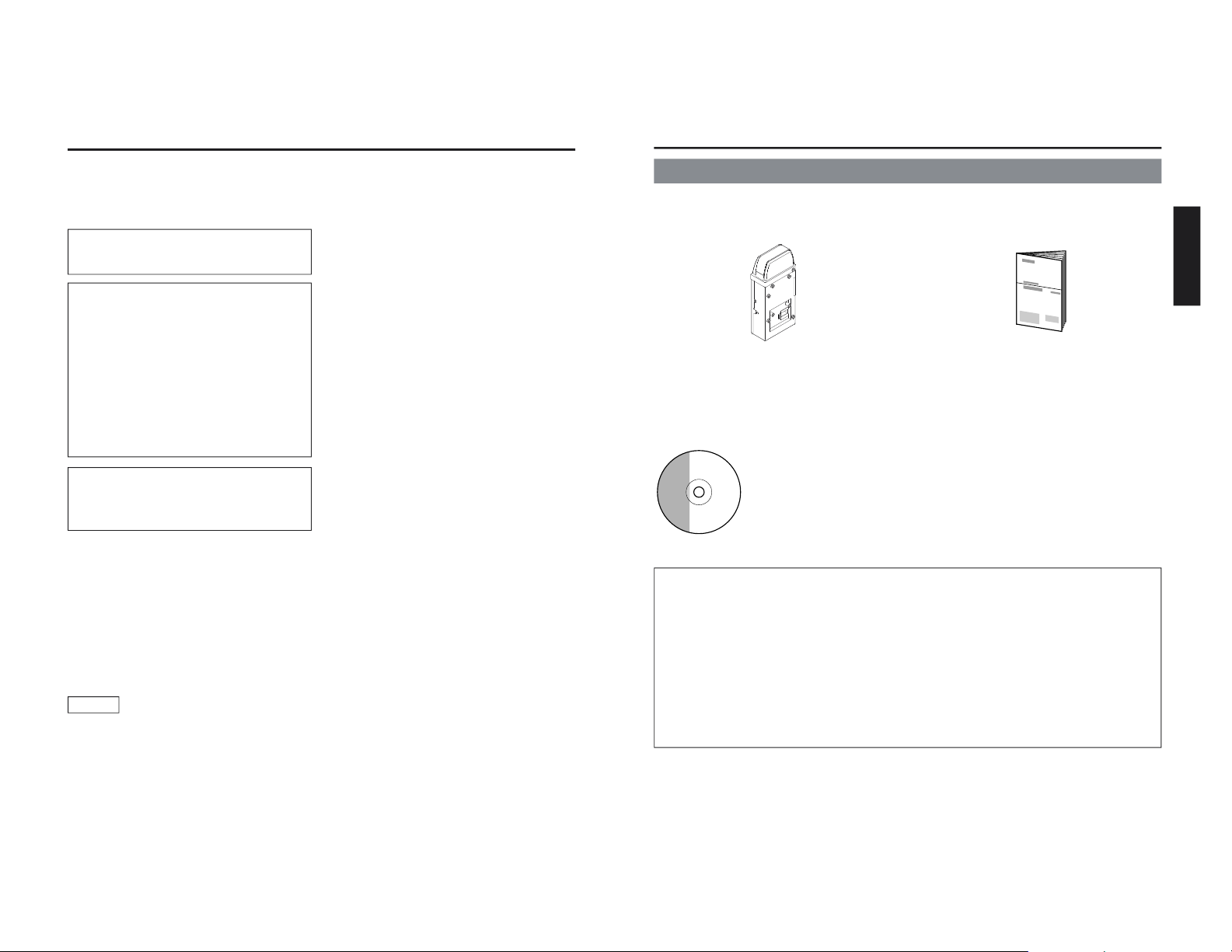
Network Pack
KA-DV5000
Adapter for encoding/decoding video/audio
data by connecting to GY-DV5000.
Setting of the KA-DV5000 is performed on the menu screen of the GY-DV5000 camcorder.
For details on the setting methods, please see the Network Pack User’s Guide (pdf) included
on the provided CD-ROM.
CD-ROM\ENU\Network Pack User’s Guide (pdf)
When the Streamproducer program included on the provided CD-ROM is installed, the Network Pack User’s Guide (pdf) is automatically installed on the PC and added to the Start
menu.
[Start/Programs/KA-DV5000U/User’s Guide]
The Adobe Acrobat Reader is required to view PDF files.
Network Pack Startup Guide
(This document)
This document describes the basic matters
for use of the Network Pack.
The following software and these Instructions are included on the provided
CD-ROM.
• Streamproducer Software
Software used for distributing movies on a network.
• Network Pack User’s Guide (pdf)
Reference guide for the Network Pack.
•
User’s Guide
(pdf)
to “Streamproducer” – the software for network distri-
bution.
Software for live broadcasting and distribution on networks.
CD-ROM
Product Components
K
A
-D
KA-DV
5
0
0
0
V5000
N
E
T
W
NETWO
R
K
P
ORK PAC
K
CK
POWER
SUPPLY
N
E
T
W
O
R
K
P
A
C
K
K
A
D
V
5
0
0
0
O
N
O
F
F
Page 4

E-4
Contents
Features .......................................................................................................................
..........................
4
Precautions ....................................................................................................................
........................
4
What the KA-DV5000 can be used for ................................................................................................... 6
Controls, Connectors and Indicators ...................................................................................................... 8
How to Attach ..................................................................................................................
.......................
9
Confirming correct attachment ............................................................................................................. 10
Installing Streamproducer .................................................................................................................... 11
Specifications .................................................................................................................
......................
12
Features
● By connecting the unit to GY-DV5000, video/audio of camera or tape playback can be encoded/
decoded in realtime. Video data is converted to MPEG-4 and audio data is converted to G726.
● Installing a LAN-card in the PC card slot enables real-time streaming.
● Installing a Compact Flash card in the PC card slot enables real-time capturing.
● Network distribution of the video/audio file created by the KA-DV5000 is possible when the
“Streamproducer” program included on the provided CD-ROM is installed on the PC.
Precautions
● Be sure to turn the camcorder’s power supply OFF before the KA-DV5000 is attached to the
camcorder.
● Be sure to turn the camcorder’s power supply OFF before inserting or removing CF (Compact
Flash) cards, etc., into and from the camcorder. Inserting or removing cards while the camcorder’s
power supply is turned ON can result in corruption of the recorded sections of the card or damage
to the card itself.
● The KA-DV5000 accepts the following cards for which operation has been confirmed: (As of August
2002)
Operating voltage 5 V or 3.3 V
Current consumption 500 mA (5 V)
• Wired LAN-card
US: EA2900-117 (Revision C) (Name of manufacturer: Socket Communications, Inc)
*1
Europe: EA2903-162 (Revision C) (Name of manufacturer: Socket Communications, Inc)
*1
Asia: EA2906-194 (Revision C) (Name of manufacturer: Socket Communications, Inc)
*1
(The Revision designation is indicated in the upper right of the serial number label affixed to the
package.)
• Wireless LAN-card
TEW-201PC,TEW-202CF (Name of manufacturer: TRENDware)
WCF11 (Name of manufacturer: LINKSYS)
*2
• CF (Compact Flash) card
SDCFB-16 ~ SDCFB-256 (Name of manufacturer: SanDisk)
*1
*1: Use PCMCIA card TYPE 1 or TYPE 2 adapter
*2: Use PCMCIA card TYPE 2 adapter
Do not use other cards that those for which operation has been confirmed. Improper installation
may cause damage to the KA-DV5000.
For the latest operational check card, visit the website below or contact your JVC dealer.
http://www.jvc-victor.co.jp/english/pro/prodv/stream/
* The names of actual companies and products mentioned in this document may be the trademarks or
registered trademarks of their respective owners.
In this document, symbols like ™, ®, ©, etc. have been omitted.
E-5
English
Precautions (cont’d)
Streamproducer Operating Environment
● Under the following conditions, the Streamproducer can be used in the required operating environment.
• When using 1 camera or 1 file.
• When recording of the camera image is not performed.
• When switched distribution is not performed.
Required operating environment
Hardware
CPU Pentium III 700 MHz
Memory 128 MB
Display XGA (1024 X 768)
Hard disk * 50 MB for installation
* 1 hour viewing time requires empty hard disk space equivalent to 25 MB (high
compression) to 200 MB (low compression).
Network * 1 LAN system for connecting the network pack
* Internet connection to download codec program for playback of moving pictures
* Other network environment for distribution if distribution is to be performed in other
environment than that described above
Software
OS Windows 2000 Professional (English), Windows XP Home Edition, Windows XP
Professional
Others An environment in which Windows Media Player 7.1 or later is already installed is
necessary for installation of Streamproducer
● When using multiple cameras or files, the following operating environment is recommended in order to
make full use of the application’s functions.
Recommended Operation Environment
Hardware
CPU Pentium 4 2.2 GHz or higher
Memory 512 MB or more
Display SXGA (1280 X 1024) or more
Other operating environment demands are the same as the required operating environment demands.
MEMO
The described required operating environment and recommend operating environment are both
meant as guidelines to ensure optimal use of the application but are not meant as guarantee of
operation. Also, even if you use a computer that complies with the operating environment, optimal
use of the application may not be obtainable due to the configuration of your system.
Page 5
E-6
RECREC
CAMCAM
VTRVTR
AUTAUTO
BARSBARS
IRISIRIS
LOLUXLOLUX
GAINGAIN
SHUTTERSHUTTER
ALCALC
STEPSTEP
0dB0dB
STEPSTEP
OFFOFF
AUTAUTO
MANUALMANUAL
WHITE BALWHITE BAL
ONON OFFOFF
ONON OFFOFF
ONON OFFOFF
VTR CONTROLVTR CONTROL
REWREW PLAPLAYPAUSEAUSE
FFFF
STSTOPOP
NETWORKNETWORK
PORTPORT
NUMBERNUMBER
CAMERA&VTRCAMERA&VTR
CONTROLCONTROL
ENCODEENCODE
PARAMETERSARAMETERS
STREAMSTREAM
CAPTURECAPTURE
SETUPSETUP
FAW
CLOSE
-3dB
1/250
-3
OK
CANCEL
(c) copyright 2002 VICTOR COMPANY OF JAPAN, LIMITED. All rights reserved
CAM&VTR CONTROL
MONITOR
EDITSEARCH
FILTER
STATUS
SHUTTER
MENU
AUTO IRIS
BACK L
NORMAL
SPOT L
STRETCH
NORMAL
COMPRESS
FULL AUTO
BLACKLOL
UX
MODE
POWER
O
NOFF
VTR
OPEN
VTR
CAM
1
3200K
5600K
5600K
5600K
ND
/
/
ND
2
.3
.4
1
8
1
64
CH-1
AUDI
O INPUT
AUDIO
SELECT
CH-2
CH-1
CH-2
FR
ONT
R
EAR
A
UTO
MA
NUAL
AUDIO
LEVEL
CH-1 CH-2
PULL
OPEN
LCDB
RIGHTDISPLAY
NETWORK
PACK
KA-DV5000
POWER
SUPPLY
ONOFF
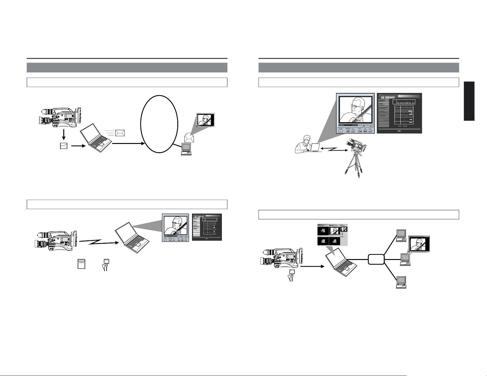
What the KA-DV5000 can be used for
Sending camera video/audio by email using CF (Compact Flash) card
Viewing and filing camera images on your PC using “Streamcapture”
Operation method
☞
See Network Pack User’s Guide (pdf) “CF card recording”
1. Using the KA-DV5000 for recording
the camera image on a CF card.
2. Sending an image file stored on a
CF card as an e-mail attachment
1. Using the KA-DV5000
to transfer the camera
images to a PC
2. Using Streamcapture for
viewing and/or filing the
camera images on a PC
Operation method
☞
• See “LAN card”, “Streamcapture” in the Network Pack User’s Guide (pdf)
• See the User’s Guide to the “Streamproducer” software for network distribution.
Operating environment
• Windows 2000, Windows XP Home Edition, Windows XP Professional
• Internet Explorer 5.01, 5.5 or 6.0
INTERNET
MONITOR
EDITSEARCH
FILTER
STATUS
SHUTTER
MENU
AUTO IRIS
BACK L
NORMAL
SPOT L
STRETCH
NORMAL
COMPRESS
FULL AUTO BLACK LOLUX
MODE
POWER
ON OFF
VTR
OPEN
VTR
CAM
1
3200K
5600K
5600K
5600K
ND
/
/
ND
2
.3
.4
1
8
1
64
CH-1
AUDIO INPUT
AUDIO SELECT
CH-2
CH-1
CH-2
FRONT
REAR
AUTO
MANUAL
AUDIO
LEVEL
CH-1 CH-2
PULL
OPEN
LCDBRIGHT DISPLAY
NETWORK
PACK
KA-DV5000
POWER
SUPPLY
ONOFF
• JavaScript enabled
E-7
English
Connecting a notebook computer for remote control with monitor
Distributing camera images on an intranet
1. Using the KA-DV5000
to transfer the camera
images to a PC
2. Using Streamproducer to
redistribute the camera images
transferred to the PC
Operating environment
• Windows 2000, XP
• Internet Explorer 5.01, 5.5 or 6.0
• JavaScript enabled
3. Using Windows Media Player
to view the distributed camera
images on a PC
Operating environment
• Windows 98 (SE), Me, 2000,
XP
Camera settings and VTR control can be performed using a notebook computer.
What the KA-DV5000 can be used for (cont’d)
Operation method
☞
See “Streamcodec” in the Network Pack User’s Guide.
Operation method
☞
• See the User’s Guide to the “Streamproducer” software for network distribution.
• See “Network settings”, “LAN card” in the Network Pack User’s Guide (pdf)
HUB
Windows Media Server
MONITOR
EDITS
EARCH
F
ILTER
STATUS
SHU
TTER
M
ENU
AUTO IRIS
BACK L
NORMAL
SPOT L
STRETCH
NORMAL
COMPRESS
FULL AUTO BLAC
K
LOLU
X
MODE
POWER
ON OFF
VTR
OPEN
VTR
CAM
1
3200K
5600K
5600K
5600K
ND
/
/
ND
2
.3
.4
1
8
1
64
CH-1
AUDIO INP
UT
AUDIO SELE
CT
CH-2
CH-1
CH-2
FRONT
REAR
AUTO
MANUAL
AUDIO
LEVEL
CH-1 CH-2
PULL
OPEN
LCD
BRIGHT
D
ISPLAY
N
ETWORK
PACK
K
A-DV5000
PO
WER
SU
PPLY
ON
OFF
M
O
N
I
T
O
R
E
D
I
T
S
E
A
R
CH
FI
L
TE
R
S
T
A
T
U
S
SH
U
T
T
E
R
M
E
N
U
A
U
T
O
I
R
I
S
B
A
C
K
L
N
O
R
M
A
L
S
P
O
T
L
S
T
R
E
T
C
H
N
O
R
M
A
L
C
O
M
P
R
E
S
S
F
U
L
L
A
U
T
O
B
L
A
C
K
L
O
L
U
X
M
O
D
E
P
O
W
E
R
O
N
O
F
F
V
T
R
O
P
E
N
V
T
R
C
A
M
1
3
2
0
0
K
5
6
0
0
K
5
6
0
0
K
5
6
0
0
K
N
D
/
/
N
D
2
.
3
.
4
1
8
1
6
4
C
H
1
A
U
D
I
O
I
N
P
U
T
A
U
D
I
O
S
E
L
E
C
T
C
H
2
C
H
1
C
H
2
F
R
O
N
T
R
E
A
R
A
U
T
O
M
A
N
U
A
L
A
U
D
I
O
L
E
V
E
L
C
H
1
C
H
2
P
U
L
L
O
P
E
N
L
C
D
B
R
I
G
H
T
D
I
S
P
L
A
Y
N
E
T
W
O
R
K
P
A
C
K
K
A
D
V
5
0
0
0
P
O
W
E
R
S
U
P
P
L
Y
O
N
O
F
F
RECREC
CAM
VTR
AUTO
BARS
IRIS
LOLUXLOLUX
GAINGAIN
SHUTTER
ALC
STEP
0dB
STEP
OFF
AUTO
MANUMANUAL
WHITE BWHITE BALAL
ON OFFOFF
ONON OFF
ON OFF
VTR CONTRVTR CONTROLOL
REW PLAY PAUSE
FF
STSTOPOP
NETWNETWORKORK
PORPORT
NUMBERNUMBER
CAMERA&VTRCAMERA&VTR
CONTRCONTROLOL
ENCODEENCODE
PARAMETERSARAMETERS
STREAMSTREAM
CAPTURECAPTURE
SETUPSETUP
FAW
CLOSE
-3dB
1/250
-3
OK
CANCEL
(c) copyright 2002 VICTOR COMPANY OF JAPAN, LIMITED. All rights reserved
CAM&VTR CONTRCAM&VTR CONTROLOL
Page 6
E-8
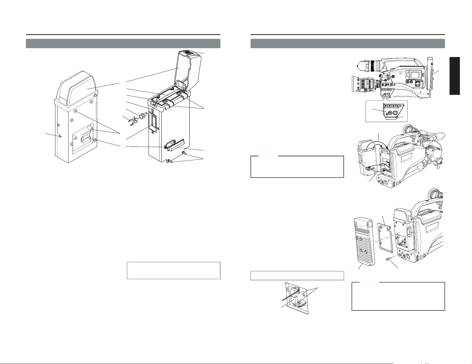
1 Power switch
2 Camera connection terminal
For connecting DV camcorder (GYDV5000). (☞ See page 9)
3 PC card slot
For inserting LAN card, Compact Flash
card, etc.
4 Main unit mounting hooks
Used when mounting to the main unit by
hooking to the cut-away section of the
camcorder.
5 EJECT button
Press when ejecting card.
6 Service terminal
Do not use.
7 Lock/release button
To open the cover, press the [PUSH]
section and lift.
8 Cover
Cover for the PC card slot. The cover can
be removed by opening and twisting in a
backward direction.
9 Battery case mounting screws
Screws for mounting the battery case after
attaching the main unit.
0 Main unit mounting screws
Used when mounting the main unit to the
camera.
A Battery case wire passage
B Cable clamp mounting hole
Hole for attaching the included cable
clamp. Remove the bushing before
attaching the cable clamp.
C Bushing
D Cable clamp (included)
For use with LAN card cable
and LAN cable.
¡ Remove the busing.
Remove by pinching the head of the
bushing.
™ Attach the cable clamp
Controls, Connectors and Indicators
K
A
-D
KA-DV
5
00
0
V5000
NETWNETWORK PORK PACKCK
POWER
SUPPLY
NETWORK
PACK
KA-DV5000
ON
OFF
2
0
1
4
8
3
5
B
C
9
6
A
7
¡
™
D
E-9
English
7
6
How to Attach
MONITOR
EDITSEARCH
FILTER
STATUS
SHUTTER
MENU
AUTO IRIS
BACK L
NORMAL
SPOT L
STRETCH
NORMAL
COMPRESS
FULL AUTO BLACK LOLUX
MODE
POWER
ON OFF
VTR
OPEN
VTR
CAM
1
3200K
5600K
5600K
5600K
ND
/
/
ND
2
.3
.4
1
8
1
64
CH-1
AUDIO INPUT
AUDIO SELECT
CH-2
CH-1 CH-2
FRONT
REAR
AUTO
MANUAL
AUDIO
LEVEL
CH-1 CH-2
PULL
OPEN
LCDBRIGHT DISPLAY
POWER
ON OFF
VTR
1
2
Below is the procedure for attaching the main
unit to the DV camcorder.
Mount using the procedure shown below.
1
Tu rn off the camcorder power.
2 Remove the battery case.
Remove the battery case mounting screws on
the back of GY-DV5000, remove the battery
case and remove the internal connector.
☞ See page 35 of the GY-DV5000 Instruction
Manual
3 Insert the connector wire of the camcorder
through the back of the network pack to the
front.
4 Tilt the network pack diagonally, set the upper
hooks on the cut-away section of the
camcorder from the top and turn downward.
5 Align the connectors of the network pack and
camcorder and connect.
6 Mount the network pack to the camcorder
using the 2 mounting screws on the lower
section of the network pack.
7 Mount the battery case on the back of the
network pack.
Insert the cushion on the back of the network
pack, connect the connector from the network
pack to the connector on the battery case,
clamp wires as shown below, and fix the
battery case to the back of the network pack
using the mounting screws.
☞ See page 35 of the GY-DV5000 Instruction
Manual
Make sure the cushion does not shift
when hooking the network pack to the cutaway section of the camera.
Caution
BH cushion
(included)
3
5
4
Fix unused connector wire to the back of
the camera or back of network pack using
the clamps so that the wire does not
become pinched.
Caution
Storing the connector
To battery case
Clamps
Place vertically
and clamps
Page 7
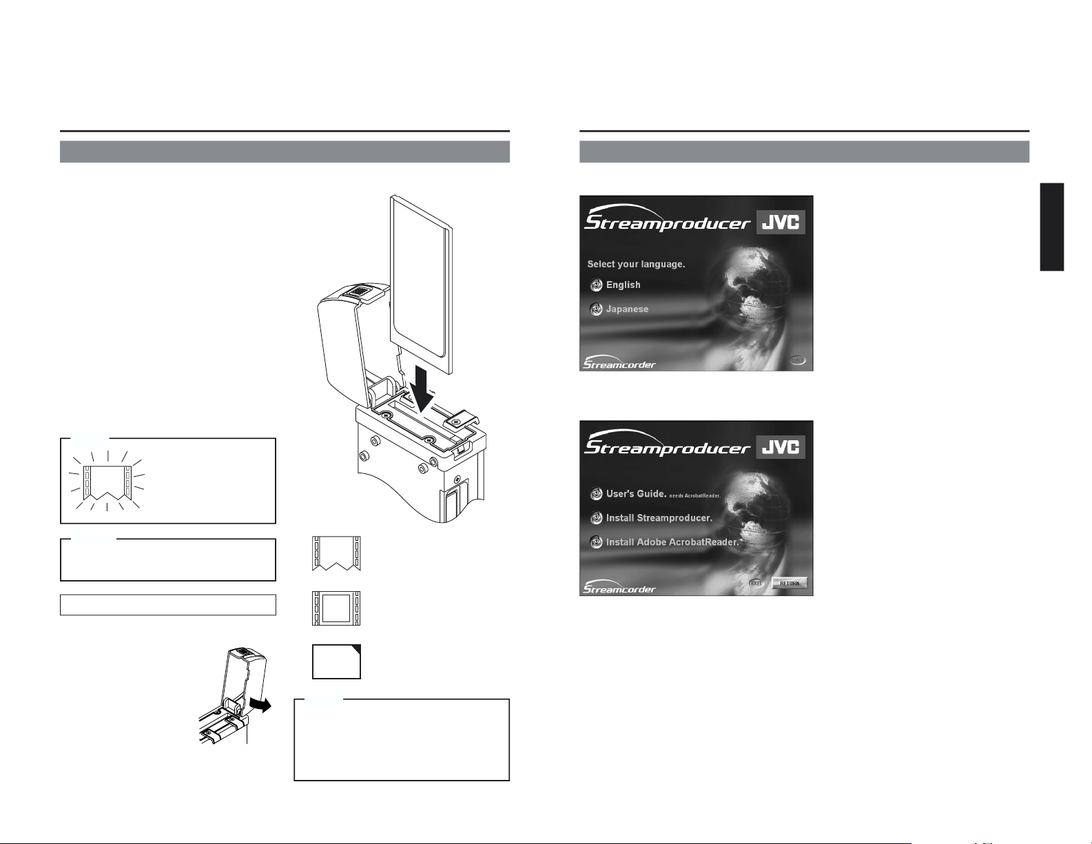
E-10
: Card not inserted
e
: LAN card
C
F
: Compact Flash card
Check to see whether the main unit has been
mounted correctly using the procedure shown
below.
1 Tu rn off the power of GY-DV5000 and KA-
DV5000.
2 Press the button on the side of the main
unit, open the cover and insert a card in
the card slot.
3 Close the cover and turn on the KA-
DV5000 power.
4 Tu rn on the GY-DV5000 power.
5 Check the card status. Check to see that
the card status according to the card type
is displayed on the LCD monitor and
viewfinder screen of GY-DV5000.
Depending on the card shape, the cover
may get in the way or may not close
correctly. In this case, the cover can be
removed by twisting the cover backward
while it is open.
Confirming correct attachment
Memo
Removing the cover
1 Open the cover.
2 Remove by pressing in
as shown on the right
so that the cover
widens on sides.
Attaching the cover
Perform the steps
above in reverse.
Be sure to turn off the GY-DV5000 power
before removing card.
Caution
Removing/attaching the cover
During initialization
after the power is
turned on, the card
status display shown
on the left is displayed.
Memo
E-11
English
Installing Streamproducer
1.
Insert the CD-ROM with Streamproducer into the CD-ROM drive.
Wait until the access lamp of the CD-ROM
drive goes out.
The screen shown on the left appears.
2.
Click on “English”.
The screen shown on the left appears.
3.
Click on “Install Streamproducer”.
The Installer starts up.
Detailed information on how to operate the Streamproducer is described in the “Read
User’s Guide”, so please refer to this.
The “Read User’s Guide” can be invoked by selecting:
Start menu/Programs/Streamproducer/User’s Guide.
Page 8
E-12
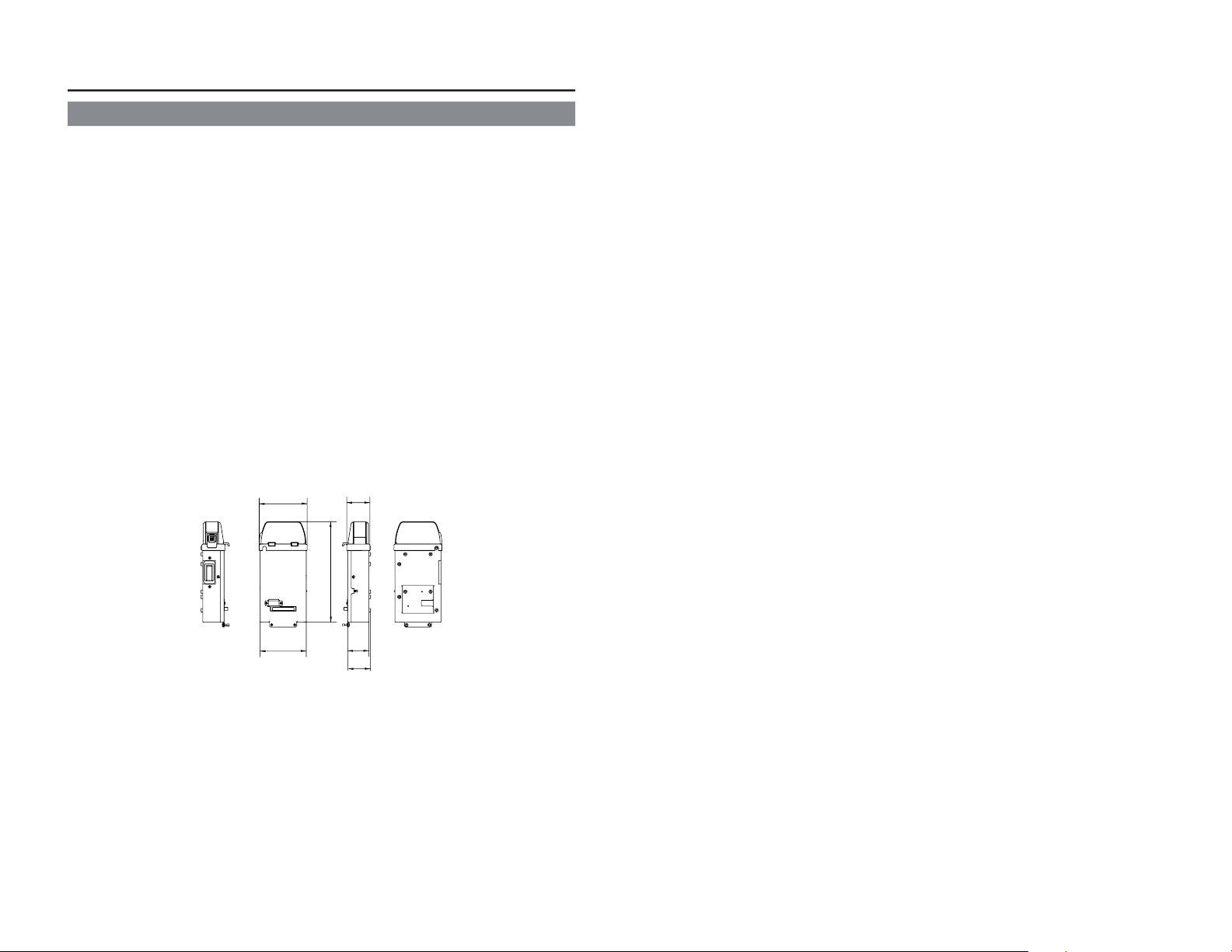
Specifications
● Mass: 480 g (main unit only)
● Power supply: Supplied from the GY-DV5000
● Power consumption: DC 12 V
—
---
0.5 A (main unit only)
● Allowable operating temperature: 0°C to 40°C
● Allowable storage temperature: –20°C to 60°C
● Allowable operating humidity: 30% to 80% RH
● Provided accessories CD-ROM
INSTRUCTIONS
Warranty Card (USA and Canada only)
BH Cushion
Cable Clamp
● External Dimensions (Unit: mm)
Design and specifications are subject to change without notice.
(40)
PACK
NETWORK
KA-DV5000
PACK
NETWORK
KA-DV5000
POWER
SUPPLY
ON OFF
83.2
80
174.5
37
40.2
Page 9
KA-DV5000
LST0103-001A
NETWORK PACK
User’s Guide
KA-DV5000KA-DV5000
N
E
TW
O
R
K
P
NETWORK PA
C
K
ACK
P
O
W
E
R
S
U
P
P
L
Y
NETW
ORK
PAC
K
KA-DV5000
O
N
O
F
F
KA-DV5000
NETWORK PACK
VICTOR COMPANY OF JAPAN, LIMITED
is a registered trademark owned by VICTOR COMPANY OF JAPAN, LTD.
is a registered trademark in Japan, the U.S.A., the U.K. and many other countries.
© 2002 VICTOR COMPANY OF JAPAN, LIMITED
LST0103-001A
Page 10
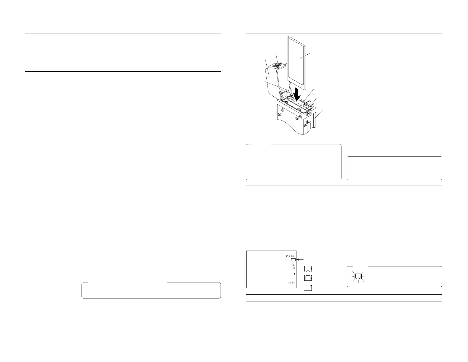
When attaching Network Pack KA-DV5000 to DV Camcorder GY-DV5000, network related menus are added to the GY-DV5000 menu
3
e
C
F
C
F
CF memory card or
LAN card
KA-DV5000
Card slot
EJECT button
Caution
●
Make sure the power of GY-DV5000 is off when inserting/
removing a CF memory card/LAN card. Inserting/removing
a card with the unit power on may damage the data storage
section of the CF memory card or the card itself.
●
Do not use the wireless LAN card continuously for more
than 48 hours.
LCD screen
Card status display
: No card
: LAN card
: CF memory card
Inserting card
1.
Turn off the GY-DV5000 power.
2.
Press and hold the lock release button and open the cover.
3.
Insert a card into the KA-DV5000 card slot. Then, close the cover.
● The cover may not close depending on the wired LAN card or the card shape. In this case, remove the cover by pressing section
A and pulling on the cover.
4.
Turn on the GY-DV5000 power.
5.
Turn on the KA-DV5000 power.
● Card status according to the inserted card type is displayed on
the LCD screen/viewfinder screen. (☞ page 4)
(The viewfinder will show the status in black and white.)
Memo
When turning the power on, the card status
display shown on left will flash during initialization.
Introduction
Inserting/removing CF memory card/LAN card
● The KA-DV5000 accepts the following cards for which operation has
been confirmed: (As of August 2002)
Operating voltage 5 V or 3.3 V
Current consumption Max. 500 mA (5 V)
• Wired LAN-card
US: EA2900-117 (Revision C) (Name of manufacturer: Socket
Communications, Inc)
*1
Europe: EA2903-162 (Revision C) (Name of manufacturer: Socket
Communications, Inc)
*1
Asia: EA2906-194 (Revision C) (Name of manufacturer: Socket
Communications, Inc)
*1
* Revision indicated on the upper right of package production label.
• Wireless LAN-card
TEW-PC16 (firmware version 0.8.3 or later) (Name of manufacturer:
TRENDware)
WCF11 (Name of manufacturer: LINKSYS)
*2
TEW-201PC
TEW-202CF
Wireless Networker Compact Flash
(Name of manufacture: SYMBOL TECHNOLOGIES INC.)
FCCID: H9PLA4B7P
TEW-PC202CF
(Name of manufacture: TREND net)
FCCID: MXF-F90120
Low Power WLAN CARD
(Name of manufacture: Socket Communications, INC)
FCCID: H9PLA4137P
AIR-PCM350
(Name of manufacture: Cisco Systems)
FCCID: LDK102040
• CF (Compact Flash) card
SDCFB-16 ~ SDCFB-256 (Name of manufacturer: SanDisk)
*1
*1: Use PCMCIA card TYPE 1 or TYPE 2 adapter
*2: Use PCMCIA card TYPE 2 adapter
Lock release button
Cover
Section A
For the latest operational check card, visit the website below
or contact your JVC dealer.
http://www.jvc-victor.co.jp/english/pro/prodv/stream/
Removing card
1.
Turn off the GY-DV5000 power, or turn off the KA-DV5000 power.
2.
Open the cover, press the EJECT button of KA-DV5000 and remove the card.
screen.
This User’s Guide explains settings for the network related menus, operation for recording streaming data to a CF (Compact Flash)
memory card and operation for sending streaming data using a LAN card. When a LAN card is connected, menu screen settings for the
Network Pack and GY-DV5000 can be operated from your PC.
Contents
Introduction
Inserting/removing CF memory card/LAN card ............................................................................................................................... 3
LCD screen/viewfinder screen .........................................................................................................................................................4
Menu screen
Menu screen structure ..................................................................................................................................................................... 5
NETWORK PACK CONFIG menu screen items ...............................................................................................................................6
Setting the NETWORK PACK CONFIG menu screen....................................................................................................................... 8
Returning the NETWORK PACK CONFIG menu screen to factory settings .................................................................................... 9
Network settings
Setting the NETWORK SET menu screen ...................................................................................................................................... 10
NETWORK SET menu screen items ............................................................................................................................................... 11
USER PAGE can be customized .................................................................................................................................................... 12
Making network related settings .................................................................................................................................................... 13
Detailed IP settings (LAN) .............................................................................................................................................................. 14
Detailed network settings (WLAN) ................................................................................................................................................. 15
Recording on a CF card
Formatting a CF memory card ....................................................................................................................................................... 17
CF memory recording time............................................................................................................................................................. 17
Recording video on a DV cassette tape and CF memory card ..................................................................................................... 18
Recording video on a CF memory card only ................................................................................................................................. 19
Recording playback signals of a DV cassette tape on a CF memory card ................................................................................... 20
Deleting all clip files on a CF memory card ................................................................................................................................... 21
Movie clips
Playing back video/audio recorded on a CF memory card ........................................................................................................... 22
Protecting a clip file on a CF memory card .................................................................................................................................... 24
Deleting a clip file on a CF memory card ....................................................................................................................................... 25
Playing back CF memory card clips on your PC ........................................................................................................................... 26
LAN card
Sending video using LAN card while recording on a DV cassette tape ........................................................................................ 27
Sending video using a LAN card (no DV cassette tape recording)............................................................................................... 28
Sending playback signals of a DV cassette tape using a LAN card ............................................................................................. 29
Network Pack Setup
Controlling GY-DV5000/KA-DV5000 via LAN a card ...................................................................................................................... 30
CAM & VTR CONTROL screen ...................................................................................................................................................... 31
NETWORK SETUP screen .............................................................................................................................................................. 33
PORT SETUP screen ......................................................................................................................................................................34
ENCODE PARAMETERS screen .................................................................................................................................................... 35
Streamcapture screen (Playing back video/audio using a PC and saving to file) ......................................................................... 36
Others
Troubleshooting.............................................................................................................................................................................. 40
Checking communication/connection ............................................................................................................................................ 42
Terminology .................................................................................................................................................................................... 43
Caution Cautionary notes concerning operation of the unit
Memo Reference such as restrictions of features, etc.
☞ Reference page or item
Characters and symbols used in this instruction book
* In general, the names of products manufactured by other companies and mentioned in these
instructions are trademarks or registered trademarks of these companies.
Symbols like ™, ©, ®, etc., are not used in these instructions.
2
Page 11

Introduction
5
Menu screen
Menu screen structure
When attaching Network Pack KA-DV5000 to DV Camcorder GY-DV5000, NETWORK PACK CONFIG menu and MOVIE CLIP menu
are added to the GY-DV5000 TOP MENU screen.
CAMERA O P ERA T I O
MENU
N
CAMERA P ROCE SS ..
..
AUD I O / V I DEO ..
LCD / VF . .
TC / UB / CL OCK . .
OTHER S . .
..
FILE MAN E. .AG
MEN U A L L R ES ET C ELAN C
NETWORKPACKCONFIG
EXIT
AUD I O / V I DEO ..
LCD / VF . .
TC / UB / CL OCK . .
OTHER S . .
..
FILE MAN E. .AG
MEN U A L L R ES ET C ELAN C
NETWORKPACKCONFIG
MOVIE CLIP . .
EXIT
MENU
NE TWO RK T . .
..
..
SE
ORTWENKACKPONCIG
F
ENCODE SET
MPE G R EC
T
RGI
MOV I ECLIPSET
MEN U R E S ET C AN CE L
PAGE BACK
PIX S I ZE 0 x24032
384Kb/s
XMA
ODNCEEET
S
BIT R ETA
MAX F RAMEARTE
PAGE BACK
HOST NAME. .
..
..
WOETNRKETS1/2
]
[
FOF
DHC P
IP ADDRESS
NE TM SA
K
..GATEWA
Y
NE XT PAGE
PAGE BACK
MC 0 0 5.0asf WR/
IEOVMCIP
L
02 03/02/
09 0 0:00:
MC 0 0 6.0asf WR/
02 03/02/
09 3 0:25:
MC 0 0 7.0asf WR/
02 03/02/
10 1 0:55:
MC 0 0 8.0asf WR/
02 03/02/
11 0 0:00:
PAGE BACK
DEL E ETALL NCELCA
NCELCA
IEOVMCIP
L
FORMAT
PL AY MODE
S
ET
PAGE BACK
REPEAT
MODE switch: When CAM-A or CAM-B is selected
TOP MENU screen
NETWORK PACK CONFIG
menu screen
NETWORK SET menu screen
(☞ page 10)
Configuration screen of
each item
When MODE switch:
VTR is selected.
TOP MENU screen
MOVIE CLIP list screen
(☞ page 22)
ENCODE SET menu screen
MOVIE CLIP SET menu screen
* Example display when there are clip
files in the CF memory card
LCD screen/viewfinder screen
Information from Network Pack KA-DV5000 is displayed on the GY-DV5000 LCD screen/viewfinder screen.
CF FULL!
qCard status displays
Display
e
(White display)
e
(Red display)
C
F
(White display)
C
F
(Red display)
X
Flashing display
Description
No card is inserted in Network Pack.
Flashing display during initialization (after
power on).
LAN card is inserted in Network Pack.
Video/audio data is being sent from LAN
card.
CF memory card is inserted in Network Pack.
CF memory card is being recorded with data.
Card is inserted in Network Pack but transmission is not available.
There is possibility of unit malfunction.
Contact your nearest JVC dealer.
wCF Memory card warning display
Displays CF memory card status and system errors.
* For details concerning warning displays, see page 40.
No colors will be shown on the viewfinder.
4
Page 12

Menu screen
䢇 indicates default factory setting.
Item
NETWORK SET
ENCODE SET
PIX SIZE
VIDEO RATE
MAX FRAME
RATE
( ): for E model
PAGE BACK
MPEG REC
Setting
䢇320 × 240
160 × 120
56K
128K
256K
䢇384K
512K
MAX
䢇MID
MIN
BIT RATE
(bps)
512K
384K
256K
䢇TRIG
SPLIT
OFF
NETWORK PACK CONFIG menu screen items
Description
Displays menu screen for network related settings such as DHCP, IP address, subnet mask,
etc. (☞ page 11)
Displays menu screen for setting video and audio compressions.
Sets the video compression size.
320 × 240: Sets the image size to 320 × 240 pixels. (SIF)
160 × 120: Sets the image size to 160 × 120 pixels. (QSIF)
(1/4 image size of SIF.)
Sets streaming speed (bps).
56K: MPEG4 24 kbps G726 16 kbps
128K: MPEG4 104 kbps G726 16 kbps
256K: MPEG4 232 kbps G726 24 kbps
384K: MPEG4 352 kbps G726 32 kbps
512K: MPEG4 472 kbps G726 40 kbps
Sets the frame rate per second. Settings are as shown below.
PIX SIZE
320 × 240 160 × 120
MAX MID MIN MAX MID MIN
NTSC 15 10 7.5 30 15 10
PAL 12.5 5 5 25 12.5 12.5
NTSC 15 10 7.5 30 15 10
PAL 12.5 5 5 25 12.5 5
NTSC 15 7.5 5 30 15 7.5
PAL 12.5 5 5 25 12.5 5
Pressing the SHUTTER dial returns to the NETWORK PACK CONFIG menu screen.
Selects the operation method for recording video data to a CF memory card or sending data
to a remote media from a LAN card.
TRIG: Pressing the VTR trigger button of GY-DV5000 starts operation. Use this setting
when simultaneously recording to a DV tape.
SPLIT: Use this setting when recording or transferring with CF memory card or LAN card
only. Operation starts when pressing the VTR trigger button on the side of GYDV5000.
Memo
When SPLIT is selected, the unit will not operate even when pressing the VTR trigger
button on the front or on the lens.
OFF: Recording will not be made to the CF memory card and streaming data from the
LAN card will not be recorded/sent to the PC even when pressing the VTR trigger
button of GY-DV5000.
BIT RATE
(bps)
NTSC 7.5 5 3 15 10 7.5
128K
PAL 5 5 1 12.5 12.5 5
NTSC 3 1 1 10 7.5 5
56K
PAL 1 1 1 12.5 5 5
* The frame rates shown in the table are not
guaranteed values.
PIX SIZE
320 × 240 160 × 120
MAX MID MIN MAX MID MIN
→
OVER
Menu screen
Item
MOVIE CLIP SET
DELETE ALL
FORMAT
PLAY MODE
PAGE BACK
MENU RESET
PAGE BACK
䢇CANCEL
EXECUTE
䢇CANCEL
EXECUTE
OFF
REPEAT 1
䢇REPEAT
䢇CANCEL
EXECUTE
Setting
NETWORK PACK CONFIG menu screen items
Description
Displays the menu screen for CF memory card related settings such as formatting or deleting all recorded clip files.
Selecting EXECUTE and pressing the SHUTTER dial deletes all clip files on the CF memory
card.
Protected clip files are not deleted.
Selecting EXECUTE and pressing the SHUTTER dial starts formatting the card.
All recorded clips are erased.
Playback is performed from the specified clip file to the latest clip file and pauses at the
specified clip file.
Continuously plays back the specified clip file.
Playback is performed continuously from the specified clip file to the latest clip file.
Pressing the SHUTTER dial returns to the NETWORK PACK CONFIG menu screen.
Selecting EXECUTE and pressing the SHUTTER dial returns NETWORK PACK CONFIG
menu screen settings to the original factory settings.
Pressing the SHUTTER dial returns to the TOP MENU screen.
6
7
Page 13

Menu screen
9
Menu screen
Returning the NETWORK PACK CONFIG menu screen to factory settings
1.
Press the STATUS button for about 1 seconds to display the TOP MENU screen.
2.
Check to see that the card status display has changed from a flashing to constant
display.
3.
Turn the SHUTTER dial to select NETWORK PACK CONFIG and press the SHUT-
TER dial.
● The NETWORK PACK CONFIG menu screen appears.
4.
Turn the SHUTTER dial to set MENU RESET to “EXECUTE” and press the SHUT-
TER dial.
● When resetting the menu, “MENU RESET..” will appear at the bottom of the
screen for about 5 seconds.
● The NETWORK PACK CONFIG menu screen settings will return to the factory
settings.
NETWORK PACK CONFIG
menu screen
NE TWOR K T . .
..
..
..
SE
ORTWENKACKPONCIG
F
ENCODE SET
MPE G R EC
T
RGI
MOV I ECLIPSET
MEN U R E S ET
MEN U R E S ET
EXECUTE
PAGE BACK
MONITOR
EDITSEARCH
FILTER
STATUS
SHUTTER
MENU
AUTO IRIS
BACK L
NORMAL
SPOT L
STRETCH
NORMAL
COMPRESS
FULL AUTO BLACK LOLUX
MODE
POWER
ON OFF
VTR
OPEN
VTR
CAM
1
3200K
5600K
5600K
5600K
ND
/
/
ND
2
.3
.4
1
8
1
64
CH-1
AUDIO INPUT
AUDIO SELECT
CH-2
CH-1 CH-2
FRONT
REAR
AUTO
MANUAL
AUDIO
LEVEL
CH-1 CH-2
PULL
OPEN
LCDBRIGHT DISPLAY
STATUS
SHUTTER
MENU
NETWORK
PACK
KA-DV5000
POWER
SUPPLY
ONOFF
STATUS
button
SHUTTER
dial
Setting the NETWORK PACK CONFIG menu screen
Menu screen settings can be made regardless of whether a card is inserted. Settings will be stored in the KA-DV5000 memor y even
when turning the power off.
STATUS
SHUTTER
SHUTTER
dial
MENU
STATUS
button
POWER switch
EDITSEARCH
MONITOR
FILTER
1
3200K
1
2
8
5600K
ND
/
.3
5600K
1
.4
5600K
/
ND
64
STATUS
SHUTTER
MENU
AUTO IRIS
FULL AUTO BLACK LOLUX
MODE
BACK L
STRETCH
VTR
NORMAL
NORMAL
COMPRESS
SPOT L
CAM
POWER
VTR
ON OFF
MODE switch
OPEN
POWER
SUPPLY
LCDBRIGHT DISPLAY
ONOFF
NETWORK
PACK
KA-DV5000
POWER SUPPLY
switch
MODE
VTR
CAM
AUDIO
PULL
LEVEL
OPEN
FRONT
REAR
CH-1 CH-2
CH-1
CH-2
AUDIO INPUT
AUDIO SELECT
CH-1 CH-2
AUTO
MANUAL
● The NETWORK PACK CONFIG menu
screen will not appear during card initial-
TOP MENU screen
MENU
display).
N
..
..
ization (flashing
CAMERA O P ERA T I O
CAMERA P ROCE SS ..
AUD I O / V I DEO ..
LCD / VF . .
TC / UB / CL OCK . .
OTHE RS . .
FILE MAN E. .AG
MEN U A L L R E SE T C E LAN C
NETWORKPACKCONFIG
EXIT
Cursor
NETWORK PACK CONFIG
menu screen
ORTWENKACKPONCIG
NE TWOR K T . .
SE
ENCODE SET
MPE G R EC
MOV I ECLIPSET
MEN U R E S ET C AN CE L
PAGE BACK
NETWORK SET menu screen
(☞ page 10)
PIX SI ZE 0 x24032
BIT ARTE
MAX F RAMEARTE
PAGE BACK
F
..
RGI
T
..
ODNCEEET
S
M
Setting
K38
4
DI
Setting
\ Settings are made by viewing the LCD screen or viewfinder screen.
If OUTPUT CHAR of the OTHERS (1/2) menu screen is set to ON, the menu
screen also appears on the monitor screen connected to the MONITOR OUT or
Y/C OUT connector.
1.
Set the POWER switch of the GY-DV5000 and KA-DV5000 to ON.
2.
Set the MODE switch.
● Set to “CAM” when shooting a video. (Light the CAM indicator.)
● Set to "VTR" for VTR playback, clip file playback or DV signal recording. (Light
the VTR indicator.)
3.
Press the STATUS button for about 1 seconds. The TOP MENU screen appears.
4.
Turn the SHUTTER dial, move the cursor (t) to NETWORK PACK CONFIG and
press the SHUTTER dial.
● The NETWORK PACK CONFIG menu screen appears.
5.
Select the item to set.
Turn the SHUTTER dial, move the cursor to the desired item to set and press the
SHUTTER dial.
● The selected menu screen appears.
● When selecting MPEG REC or MENU RESET, the setting area flashes and the
setting can be changed. Set the item according to step 7.
● When selecting NETWORK SET, the network related setting screen appears.
(☞ page 10)
6.
Select an item within the menu screen.
Turn the SHUTTER dial, move the cursor (t) to the desired item to set and press
the SHUTTER dial.
● The setting area flashes and the setting can be changed.
7.
Change the setting.
Turn the SHUTTER dial to change the setting and press the SHUTTER dial.
● Flashing of the setting area stops and the new setting is confirmed.
\ When changing multiple settings, repeat steps 6 and 7 above.
8.
Return to the TOP MENU screen.
Turn the SHUTTER dial, move the cursor (t) to PAGE BACK and press the SHUTTER dial.
9.
When quitting menu screen setting and returning to the normal screen, perform
one of the following operations.
● Press the STATUS button.
● Move the cursor (t) to EXIT in the TOP MENU screen and press the SHUTTER
dial.
8
Page 14

Network settings
Setting the NETWORK SET menu screen
When using a LAN card, network related settings for KA-DV5000 are made using NETWORK SET of the NETWORK PACK CONFIG
menu. Settings will be stored in the KA-DV5000 memory even when turning the power off.
STATUS
SHUTTER
SHUTTER
dial
MENU
STATUS
button
EDITSEARCH
MONITOR
FILTER
1
3200K
1
2
8
ND
/
5600K
.3
5600K
1
.4
/
5600K
ND
64
STATUS
SHUTTER
MENU
AUTO IRIS
FULL AUTO BLACK LOLUX
MODE
BACK L
STRETCH
VTR
NORMAL
NORMAL
SPOT L
COMPRESS
CAM
POWER
VTR
ON OFF
OPEN
POWER
SUPPLY
LCDBRIGHT DISPLAY
ONOFF
NETWORK
PACK
KA-DV5000
POWER SUPPLY
switch
AUDIO
PULL
LEVEL
OPEN
FRONT
REAR
CH-1 CH-2
CH-1
CH-2
AUDIO INPUT
AUDIO SELECT
CH-1 CH-2
AUTO
MANUAL
POWER switch
TOP MENU screen
MENU
CAMERA O P ERA T I O
CAMERA P ROCE SS ..
AUD I O / V I DEO ..
LCD / VF . .
TC / UB / CL OCK . .
OTHER S . .
FILE MAN E. .AG
MEN U A L L R ES ET C ELAN C
NETWORKPACKCONFIG
EXIT
NETWORK PACK CONFIG
NE TWOR K T . .
ENCODE SET
MPE G R EC
MOV I ECLIPSET
MEN U R E S ET C AN CE L
PAGE BACK
N
..
menu screen
ORTWENKACKPONCIG
F
SE
..
RGI
T
..
..
\ Settings are made by viewing the LCD screen or viewfinder screen.
If OUTPUT CHAR of the OTHERS (1/2) menu screen is set to ON, the menu screen
also appears on the monitor screen connected to the MONITOR OUT or Y/C OUT
connector.
Display the NETWORK SET menu screen
1.
Turn on the GY-DV5000 and KA-DV5000 power.
2.
Check to see that the card status display has changed from a flashing to constant
display.
3.
Press the STATUS button for about 1 seconds to display the TOP MENU screen.
4.
Turn the SHUTTER dial, move the cursor (t) to NETWORK PACK CONFIG and
press the SHUTTER dial.
● The NETWORK PACK CONFIG menu screen appears.
5.
Turn the SHUTTER dial, move the cursor (t) to NETWORK SET and press the
SHUTTER dial.
● The NETWORK SET [1/2] menu screen will appear.
NETWORK SET [1/2]
menu screen
WOETNRKETS1/2
HOS T NA ME . .
DHC P
..
IP ADDRESS
..
NE TM SA
K
Y
..GATEWA
NE XT PAGE
PAGE BACK
]
[
FOF
The NETWORK SET menu screen is structured by 2 pages.
\ Select NEXT PAGE and press the SHUTTER dial to display the NETWORK SET
[2/2] menu screen.
Select PAGE BACK in the NETWORK SET [2/2] menu screen and press the SHUT-
TER dial to return to the NETWORK SET [1/2] menu screen.
6.
Set DHCP to ON or OFF in the NETWORK SET [1/2] menu screen.
Items other than DHCP are set in the individual setting screen. (☞ page 11)
7.
NETWORK SET [2/2]
menu screen
WOETNRKETS2/2
..
RTSP
..
HTTP
HOCMODE
WLAN
AD
-
WLAN ESS
DI
H
WLAN C
MEUSER NA..
..PASS
RD
W
O
PAGE BACK
]
[
..
FOF
H
C2
To return to the nor mal screen after completing setting, perform one of the follow-
ing operations.
● Press the STATUS button
● Select PAGE BACK to return to the TOP MENU screen. Select EXIT in the TOP
MENU screen and press the SHUTTER dial.
10
Network settings
[1/2] screen 䢇indicates default factory setting.
Item
HOST NAME
DHCP
IP ADDRESS
NETMASK
GATE WAY
NEXT PAGE
PAGE BACK
[2/2] screen
Item
RTSP
HTTP
WLAN AD HOC
MODE
WLAN ESS-ID
WLAN WEP
KEY
WLAN CH
USER NAME
PASS WORD
PAGE BACK
Setting
Displays the host name input setting screen. (Max. 63 alphanumerical characters)
[Factory setting: none]
䢇OFF
Select whether DHCP server is used.
ON
OFF: Use this setting when using LAN connection rather than DHCP.
When this setting is used, IP ADDRESS and NETMAST, GATEWAY must also be set.
ON: Use this setting when using DHCP connection.
When using this setting, IP ADDRESS and NETMASK, GATEWAY are automatically set.
* When DHCP is set to ON, WLAN ADHOC MODE cannot be set to AHDM or IBSS.
Displays the IP address setting screen.
When using LAN connection with DHCP set to OFF, this setting is required. Set a unique IP address.
IP ADDRESS setting is not available when DHCP is set to ON.
[Factory setting] 192.168.100.101]
Displays the subnet mask input screen.
This setting is required when using LAN connection with DHCP set to OFF.
NETMASK setting is not available if DHCP is set to ON.
[Factory setting: 255.255.255.000]
Displays the gateway address input screen.
GATEWAY setting is not available when DHCP is set to ON.
[Factory setting: 192.168.100.254]
Pressing the SHUTTER dial displays the NETWORK SET [2/2] menu screen.
Pressing the SHUTTER dial returns to the NETWORK PACK CONFIG menu screen.
Setting
1
The screen for setting RTSP and HTTP port numbers appears.
:
Normally, the unit can be used without changing the factory settings.
䢇8554
If there are port restrictions for the LAN environment of your PC, consult your network administrator.
:
* When changing a port number, refer to “5-1. Connecting with Camcorder” of the “Streamproducer”
32767
User’s Guide of the network distribution software to change settings.
* Do not use the same port numbers for RTSP and HTTP.
1
* When a port number is changed, switch the power of the GY-DV5000 off once, and then switch it
:
on again.
䢇80
:
32767
䢇OFF
Wireless LAN setting
AHDM
OFF: Use this setting when performing communication via access point.
IBSS
AHDM/IBSS: Use this setting when performing communication in AD HOC mode with a PC con-
* When this item is set to AHDM or IBSS, DHCP cannot be set to ON.
Displays the wireless LAN ESS-ID input setting screen (Max. 32 alphanumerical characters)
When encrypting data, set the WEP KEY (10 characters consisting or letters a ~ f and numbers).
Must be compatible with access point authentication for the use of this item.
1CH
Wireless LAN channel setting
䢇2CH
:
14CH
Displays the user name input setting screen. (Max. 8 alphanumerical characters)
Used when controlling GY-DV5000 via LAN card. (☞ page 30)
[Factory setting: jvc]
Displays the password input setting screen. (Max. 8 alphanumerical characters)
Used when controlling GY-DV5000 via LAN card. (☞ page 30)
[Factory setting: ka-dv5k] (Password is hidden)
Caution
• Keep a memo of the password since it is only displayed during the actual setting. The password
will be hidden using asterisks (*) when accessing the password menu screen again.
• When performing MENU RESET, ka-dv5k will return to its factory settings. (☞ page 9)
Pressing the SHUTTER dial returns to the NETWORK SET [1/2] menu screen.
NETWORK SET menu screen items
Description
Description
nected with a wireless LAN card. (☞ page 15)
11
Page 15

Network settings
13
Network settings
Making network related settings
Network related settings are made in the individual input setting screens.
Here, USER NAME is set as an example. Other settings are also made in the same manner.
Example: Changing USER NAME from jvc to jvc-1234
\ Select USER NAME in the NETWORK SET [2/2] menu screen and press the
SHUTTER dial.
● The USER NAME input setting screen appears.
1.
Characters are selected from the character selection area on the bottom of the
screen.
Turn the SHUTTER dial to flash “_” in the character selection area and press the
SHUTTER dial.
● The setting changes to “jvc_” and the following digit of the setting area flashes.
2.
Turn the SHUTTER dial to select “1” in the character selection area and press the
SHUTTER. dial.
● The setting changes to “jvc_1” and the following digit of the setting area flashes.
3.
Repeat the above step to set “jvc_1234” in the setting area.
\ To delete or edit set characters, select “BS” within the character selection area and
press the SHUTTER dial.
The previous character will be deleted. The character on the left will be deleted each
time this operation is repeated.
\ The currently inputted number of characters and the maximum number of characters
are displayed on the upper right of the screen.
4.
When completed, select “ ” within the character selection area and press the
SHUTTER dial.
● NETWORK SET [2/2] menu screen returns in the LCD or viewfinder.
4/8
RSEUNA
EM
jvc
abc de fghij klmnopqrst u v
wx y z 0 12345 6 7 8 9
_
_
.
BS
¯
5
/
RSEUNA
EM
jvc 1
abc de fghij klmnopqrst u v
wx y z 0 12345 6 7 8 9
_
8
_
.
BS
¯
3/8
RSEUNA
EM
jvc
abc de fghijklmnopqrstuv
wx y z 0 12345 6 7 8 9
_
.
BS
¯
8
/
RSEUNA
EM
jvc 1234
abc de fghij klmnopqrst u v
wx y z 0 12345 6 7 8 9
_
8
_
.
BS
¯
USER NAME input setting screen
: Retur n to menu screen
Currently inputted number of characters/
max.number of characters
Setting area
Character
selection area
BS:
Backspace (
delete previous character
)
MONITOR
EDITSEARCH
FILTER
STATUS
SHUTTER
MENU
AUTO IRIS
BACK L
NORMAL
SPOT L
STRETCH
NORMAL
COMPRESS
FULL AUTO BLACK LOLUX
MODE
POWER
ON OFF
VTR
OPEN
VTR
CAM
1
3200K
5600K
5600K
5600K
ND
/
/
ND
2
.3
.4
1
8
1
64
CH-1
AUDIO INPUT
AUDIO SELECT
CH-2
CH-1 CH-2
FRONT
REAR
AUTO
MANUAL
AUDIO
LEVEL
CH-1 CH-2
PULL
OPEN
LCDBRIGHT DISPLAY
STATUS
SHUTTER
MENU
NETWORK
PACK
KA-DV5000
POWER
SUPPLY
ONOFF
SHUTTER
dial
STATUS
button
USER PAGE can be customized as desired.
USER PAGE created on a PC is uploaded by FTP.
1.
Set the unit so that NETWORK SETUP can be displayed. (☞ page 30)
2.
Create HTML on the PC using a commercially available HTML editor, etc.
Save the created HTML file under the name of “index.html”.
3.
Use a commercially available FTP program on the PC to upload index.html created in step 2 above to KA-DV5000.
FTP program settings
IP Adress : 192.168.100.101 (Input the actual IP address used.)
Remort Port : 21
USER ID : html
PASSWORD : None
\ It is also possible to upload link pages from index.html, images, etc.
Caution
●
Make sure the uploaded files do not exceed 100KB in total.
●
The HTML display will fit properly on the screen when creating at a size of about 500 X 360 pixels.
USER PAGE can be customized
12
Page 16

Network settings
MONITOR
EDITSEARCH
FILTER
STATUS
SHUTTER
MENU
AUTO IRIS
BACK L
NORMAL
SPOT L
STRETCH
NORMAL
COMPRESS
FULL AUTO
BLACK
LOLUX
MODE
POWER
OFF
VTR
OPEN
VTR
CAM
3200K
5600K
5600K
5600K
ND
.3
.4
CH-1
UDIO INPUT
UDIO SELECT
CH-2
CH-1
CH-2
ONT
REAR
MANUALAL
AUDIO
LEVEL
CH-1
CH-2
PULL
OPEN
LCD
BRIGHT
DISPLAY
NETW
ORK
CK
KA-D
V5000
WER
SUPPL
OFF
MONITOR
EDITSEARCH
FILTER
STATUS
SHUTTER
MENU
AUTO IRIS
BACK L
NORMAL
SPOT L
STRETCH
NORMAL
COMPRESS
FULL AUTO
BLACK
LOLUX
MODE
POWER
OFF
VTR
OPEN
VTR
CAM
3200K
5600K
5600K
5600K
ND
.3
.4
64
CH-1
UDIO INPUT
UDIO SELECT
CH-2
CH-1
CH-2
ONT
REAR
MANUALAL
AUDIO
LEVEL
CH-1
CH-2
PULL
OPEN
LCD
BRIGHT
DISPLAY
NETW
ORK
CK
KA-D
V5000
WER
SUPPL
OFF
MONITOR
EDITSEARCH
FILTER
STATUS
SHUTTER
MENU
AUTO IRIS
BACK L
NORMAL
SPOT L
STRETCH
NORMAL
COMPRESS
FULL AUTO
BLACK
LOLUX
MODE
POWER
OFF
VTR
OPEN
VTR
CAM
3200K
5600K
5600K
5600K
ND
.3
.4
64
CH-1
UDIO INPUT
UDIO SELECT
CH-2
CH-1
CH-2
ONT
REAR
MANUALAL
AUDIO
LEVEL
CH-1
CH-2
PULL
OPEN
LCD
BRIGHT
DISPLAY
NETW
ORK
CK
KA-D
V5000
WER
SUPPL
OFF
1ch frequency band
1ch frequency band
1ch frequency band
6ch frequency band
Example of IP address and subnet mast settings when using LAN is shown below.
Detailed IP settings (LAN)
Network settings
Example of network settings when using wireless LAN is shown below.
Detailed network settings (WLAN)
●Operation is only guaranteed for Windows 2000, Windows XP Home Edition or Windows XP Professional.
●Internet Explorer 5.0 or later
●Windows Media Player 7.01 or later
1. For 1:1 communication between PC and GY-DV5000/KA-DV5000
OPEN
EDITSEARCH
MONITOR
FILTER
1
3200K
1
2
8
5600K
NDND/
.3
5600K
1
.4
5600K
ND
64
/
POWER
SUPPL
Y
STATUS
SHUTTER
LCD
BRIGHT
DISPLAY
ONONOFF
MENU
AUDIO
PULL
LEVEL
OPEN
FRFRONT
REAR
AUTO IRIS
FULL AUTO
BLACK
LOLUX
CH-1
CH-2
CH-1
CH-2
AUDIO INPUT
MODE
BACK L
STRETCH
AUDIO SELECT
VTR
NORMAL
NORMAL
CH-1
CH-2
SPOT L
COMPRESS
AUTUTO
CAM
MANU
NETW
ORK
PACK
KA-D
V5000
POWER
VTR
ONONOFF
DHCP OFF
IP ADDRESS 192. 168. 100. 101
NETMASK 255. 255. 255. 000
10/100 BASE-T cross cable
Set a unique number to avoid doubling
PROXY SERVER NO USE
DHCP SERVER NO USE
IP ADDRESS 192. 168. 100. 100
NETMASK 255. 255. 255. 000
* For the PC settings when using a LAN card,
refer to the instruction manual included with
the LAN card.
* Up to 3 clients can access at the same time.
Set the same network group
2. For communication between PC and multiple GY-DV5000/KA-DV5000
DHCP OFF
IP ADDRESS 192. 168. 100. 101
NETMASK 255. 255. 255. 000
DHCP OFF
IP ADDRESS 192. 168. 100. 102
NETMASK 255. 255. 255. 000
OPEN
EDITSEARCH
MONITOR
FILTER
1
3200K
1
2
8
5600K
NDND/
.3
5600K
1
.4
/
5600K
ND
64
POPOWER
SUPPL
Y
STATUS
SHUTTER
LCD
BRIGHT
DISPLAY
ONONOFF
MENU
AUDIO
PULL
LEVEL
OPEN
FRFRONT
REAR
AUTO IRIS
FULL AUTO
BLACK
LOLUX
CH-1
CH-2
CH-1
CH-2
AUDIO INPUT
MODE
BACK L
STRETCH
AUDIO SELECT
VTR
NORMAL
NORMAL
CH-1
CH-2
SPOT L
COMPRESS
AUTUTO
CAM
MANU
NETW
ORK
PACK
KA-D
V5000
POWER
VTR
ONONOFF
OPEN
EDITSEARCH
MONITOR
FILTER
1
3200K
1
2
8
5600K
NDND/
.3
5600K
1
.4
/
5600K
ND
64
POPOWER
SUPPL
Y
STATUS
SHUTTER
LCD
BRIGHT
DISPLAY
ONONOFF
MENU
AUDIO
PULL
LEVEL
OPEN
FRFRONT
REAR
AUTO IRIS
FULL AUTO
BLACK
LOLUX
CH-1
CH-2
CH-1
CH-2
AUDIO INPUT
MODE
BACK L
STRETCH
AUDIO SELECT
VTR
NORMAL
NORMAL
CH-1
CH-2
SPOT L
COMPRESS
AUTUTO
CAM
MANU
NETWORK
PACK
KA-D
V5000
POWER
VTR
ONONOFF
Hub
DHCP OFF
IP ADDRESS 192. 168. 100. 103
NETMASK 255. 255. 255. 000
DHCP OFF
IP ADDRESS 192. 168. 100. 104
NETMASK 255. 255. 255. 000
OPEN
EDITSEARCH
MONITOR
FILTER
1
3200K
1
2
8
5600K
NDND/
.3
5600K
1
.4
/
5600K
ND
64
POPOWER
SUPPL
Y
STATUS
SHUTTER
LCD
BRIGHT
DISPLAY
ONONOFF
MENU
AUDIO
PULL
LEVEL
OPEN
FRFRONT
REAR
AUTO IRIS
FULL AUTO
BLACK
LOLUX
CH-1
CH-2
CH-1
CH-2
AUDIO INPUT
MODE
BACK L
STRETCH
AUDIO SELECT
VTR
NORMAL
NORMAL
CH-1
CH-2
SPOT L
COMPRESS
AUTUTO
CAM
MANU
NETW
ORK
PACK
KA-D
V5000
POWER
VTR
ONONOFF
10/100 BASE-T straight cable
Set a unique number to avoid doubling
OPEN
EDITSEARCH
MONITOR
FILTER
1
3200K
1
2
8
5600K
NDND/
.3
5600K
1
.4
/
5600K
ND
64
POPOWER
SUPPL
Y
STATUS
SHUTTER
LCD
BRIGHT
DISPLAY
ONONOFF
MENU
AUDIO
PULL
LEVEL
OPEN
FRFRONT
REAR
AUTO IRIS
FULL AUTO
BLACK
LOLUX
CH-1
CH-2
CH-1
CH-2
AUDIO INPUT
MODE
BACK L
STRETCH
AUDIO SELECT
VTR
NORMAL
NORMAL
CH-1
CH-2
SPOT L
COMPRESS
AUTUTO
CAM
MANU
NETW
ORK
PACK
KA-D
V5000
POWER
VTR
ONONOFF
PROXY SERVER NO USE
DHCP SERVER NO USE
IP ADDRESS 192. 168. 100. 100
NETMASK 255. 255. 255. 000
Caution
IP ADDRESS 192. 168. 100. XXX
NETMASK 255. 255. 255. 000
Set the same network group
●Operation is only guaranteed for Windows 2000, Windows XP Home Edition or Windows XP Professional.
●Internet Explorer 5.0 or later
●Windows Media Player 7.01 or later
1. For communication with PC without returning access point (Ad hoc mode)
OPEN
EDITSEARCH
MONITOR
FILTER
1
3200K
1
2
8
5600K
NDND/
.3
5600K
1
.4
/
5600K
ND
64
POPOWER
SUPPL
Y
STATUS
SHUTTER
LCD
BRIGHT
DISPLAY
ONONOFF
MENU
AUDIO
PULL
LEVEL
OPEN
FRFRONT
REAR
AUTO IRIS
FULL AUTO
BLACK
LOLUX
CH-1
CH-2
CH-1
CH-2
AUDIO INPUT
MODE
BACK L
STRETCH
AUDIO SELECT
VTR
NORMAL
NORMAL
CH-1
CH-2
SPOT L
COMPRESS
AUTUTO
CAM
MANU
NETW
ORK
PACK
KA-D
V5000
POWER
VTR
ONONOFF
DHCP OFF
WLAN AD HOC MODE ON
WLAN ESS ID abcdef
WLAN CH 2
IP ADDRESS 192. 168. 100. 101
NETMASK 255. 255. 255. 000
Set a unique number to avoid doubling
PROXY SERVER OFF
DHCP SERVER OFF
IP ADDRESS 192. 168. 100. 100
NETMASK 255. 255. 255. 000
* Do not perform encryption of the
wireless LAN.
Set the same network group
PC wireless LAN driver settings
NetworkType 802. 11 Ad Hoc Mode
ESS ID abcdef
Channel 2
Encryption Mode Open System
* For the PC settings when using a LAN card, refer to
the instruction manual included with the LAN card.
Cautionary items concerning Wireless LAN (WLAN)
● For the WLAN ESS ID, input the values of ESSID set in:
Ad hoc mode: PC of other party
Infrastructure: Access point
● WLAN AD HOC MODE
When IBSS is set, the NETWORK MODE setting of the wireless LAN card on the PC side must be set to 802.11 Adhoc.
When AHDM is set, the NETWORK MODE setting of the wireless LAN card on the PC side must be set to Adhoc. Depending
on the LAN card on the PC side, only 802.11 Adhoc mode may be available.
● WLAN CH is the wireless frequency band used for communication. If there is an access point, adapter, etc., using the
same band in the proximity, there may be a hindrance in the communication and may reduce throughput or the quality of
communication. When setting, check the settings of surrounding access points, etc., to avoid doubling.
2417
2427
2437
2447
2457
Frequency bands (ISM bands) and channels
(IEEE803.11b standard)
N. America : FCC / 2.412~2.462GHz (11 channels)
Europe : CE ETSI / 2.412~2.472GHz (13 channels)
Japan : 2.412~2.4835GHz (14 channels)
France : 2.457~2.472GHz (4 channels)
Spain : 2.457~2.462GHz (2 channels)
Since adjacent channels causes signal interference, channels
are normally spaced 5 channels apart.
2412
2422
2432
4ch
5ch
6ch
6ch frequency band
7ch
2442
8ch
Approx.
11MHz
1ch
2ch
3ch
1ch frequency band
1ch frequency band 1ch frequency band
2467
2452
2462
2472 2484
9ch
10ch
11ch
12ch
13ch
11ch frequency band 1ch frequency band
14ch
14ch frequency band6ch frequency band
Center
frequency
14
15
→
OVER
Page 17

Network settings
MONITOR
EDITSEARCH
FILTER
STATUS
SHUTTER
MENU
AUTO IRIS
BACK L
NORMAL
SPOT L
STRETCH
NORMAL
COMPRESS
FULL AUTO
BLACK
LOLUX
MODE
POWER
OFF
VTR
OPEN
VTR
CAM
3200K
5600K
5600K
5600K
ND
.3
.4
64
CH-1
UDIO INPUT
UDIO SELECT
CH-2
CH-1
CH-2
ONT
REAR
MANUALAL
AUDIO
LEVEL
CH-1
CH-2
PULL
OPEN
LCD
BRIGHT
DISPLAY
NETW
ORK
CK
KA-D
V5000
WER
SUPPL
OFF
MONITOR
EDITSEARCH
FILTER
STATUS
SHUTTER
MENU
AUTO IRIS
BACK L
NORMAL
SPOT L
STRETCH
NORMAL
COMPRESS
FULL AUTO
BLACK
LOLUX
MODE
POWER
OFF
VTR
OPEN
VTR
CAM
3200K
5600K
5600K
5600K
ND
.3
.4
CH-1
UDIO INPUT
UDIO SELECT
CH-2
CH-1
CH-2
ONT
REAR
MANUALAL
AUDIO
LEVEL
CH-1
CH-2
PULL
OPEN
LCD
BRIGHT
DISPLAY
NETW
ORK
CK
KA-D
V5000
WER
SUPPL
OFF
17
1.
Press the STATUS button for about 1 seconds to display the TOP MENU screen.
2.
Use the SHUTTER dial to select NETWORK PACK CONFIG menu screen ¥
MOVIE CLIP SET menu screen.
3.
Set FORMAT in the MOVIE CLIP SET menu screen to “EXECUTE” and press the
SHUTTER dial.
● The formatting begins. During formatting, “FORMAT” appears on the screen.
4.
When formatting is completed, to the MOVIE CLIP SET menu screen returns.
The FORMAT setting will retur n to CANCEL.
5.
To return to the NETWORK PACK CONFIG menu screen, select PAGE BACK and
press the SHUTTER dial.
● To return to the normal screen, press the STATUS button.
Recording on a CF card
Formatting a CF memory card
When an unformatted CF memory card is inserted and the GY-DV5000 power is turned on, “NO CF FORMAT!” appears in the LCD
screen/viewfinder screen.
NETWORK PACK CONFIG
menu screen
Set to EXECUTE
Flashing display during
formatting
DEL E ETALL NCELCA
ECUTEEX
IEOVMCIP
L
FORMAT
FORMAT
PAGE BACK
S
ET
PL AY MODE
OFF
NO CF FORMAT!
C
F
NE TWOR K T . .
..
..
SE
ORTWENKACKPONCIG
F
ENCODE SET
MPE G R EC
T
RGI
MOV I ECLIPSET
MEN U R E S ET C AN CE L
PAGE BACK
MOVIE CLIP SET
menu screen
CF memory recording time
Estimated recording time of CF memory cards is shown below:
CF memory
BIT RATE
card size
384kbps 256kbps 128kbps ~ 56kbps
16MByte 3min. 5min. 10min. or more
32MByte 7min. 11min. 20min. or more
64MByte 15min. 22min. 40min. or more
128MByte 30min. 44min. 80min. or more
192MByte 46min. 66min. 120min. or more
256MByte 61min. 88min. 160min. or more
Caution
The actual recording time may differ from the estimate recording time shown above
depending on the recording subject and movement.
MONITOR
EDITSEARCH
FILTER
STATUS
SHUTTER
MENU
AUTO IRIS
BACK L
NORMAL
SPOT L
STRETCH
NORMAL
COMPRESS
FULL AUTO BLACK LOLUX
MODE
POWER
ON OFF
VTR
OPEN
VTR
CAM
1
3200K
5600K
5600K
5600K
ND
/
/
ND
2
.3
.4
1
8
1
64
CH-1
AUDIO INPUT
AUDIO SELECT
CH-2
CH-1 CH-2
FRONT
REAR
AUTO
MANUAL
AUDIO
LEVEL
CH-1 CH-2
PULL
OPEN
LCDBRIGHT DISPLAY
STATUS
SHUTTER
MENU
NETWORK
PACK
KA-DV5000
POWER
SUPPLY
ONOFF
SHUTTER
dial
STATUS
button
DEL E ETALL NCELCA
NCECA
IEOVMCIP
L
FORMAT
S
ET
L
PAGE BACK
PL AY MODE
REPEAT
MOVIE CLIP SET
menu screen
2. For communication with PC via access point (Infrastructure mode)
DHCP OFF
WLAN AD HOC MODE OFF
WLAN ESS ID abcdef
WLAN CH 2
IP ADDRESS 192. 168. 100. 102
NETMASK 255. 255. 255. 000
DHCP OFF
WLAN AD HOC MODE OFF
WLAN ESS ID abcdef
WLAN CH 2
IP ADDRESS 192. 168. 100. 103
NETMASK 255. 255. 255. 000
Network Type (Ad Hoc/Infrastructure)
Make sure ESS ID and Channel settings
are the same.
Set a unique number to avoid doubling
IP ADDRESS 192. 168. 100. XXX
NETMASK 255. 255. 255. 000
OPEN
EDITSEARCH
MONITOR
FILTER
1
3200K
1
2
8
5600K
NDND/
.3
5600K
1
.4
/
5600K
ND
64
POPOWER
SUPPL
Y
STATUS
SHUTTER
LCD
BRIGHT
DISPLAY
ONONOFF
MENU
AUDIO
PULL
LEVEL
OPEN
FRFRONT
REAR
AUTO IRIS
FULL AUTO
BLACK
LOLUX
CH-1
CH-2
CH-1
CH-2
AUDIO INPUT
MODE
BACK L
STRETCH
AUDIO SELECT
VTR
NORMAL
NORMAL
CH-1
CH-2
SPOT L
AUTUTO
COMPRESS
CAM
MANU
NETW
ORK
PACK
KA-D
V5000
POWER
VTR
ONONOFF
OPEN
EDITSEARCH
MONITOR
FILTER
1
3200K
1
2
8
5600K
NDND/
.3
5600K
1
.4
5600K
/
ND
64
POWER
SUPPL
Y
STATUS
SHUTTER
LCD
BRIGHT
DISPLAY
ONONOFF
MENU
AUDIO
PULL
LEVEL
OPEN
FRFRONT
REAR
AUTO IRIS
FULL AUTO
BLACK
LOLUX
CH-1
CH-2
CH-1
CH-2
AUDIO INPUT
MODE
BACK L
STRETCH
VTR
NORMAL
NORMAL
SPOT L
COMPRESS
CAM
POWER
VTR
ONONOFF
Set the same network group
AUDIO SELECT
CH-1
CH-2
AUTUTO
MANU
NETW
ORK
PACK
KA-D
V5000
S TATI O N
ESS ID abcdef
Channel 2
Encryption Mode Open System
Detailed network settings (WLAN)
DHCP OFF
WLAN AD HOC MODE OFF
WLAN ESS ID abcdef
WLAN CH 2
IP ADDRESS 192. 168. 100. 101
NETMASK 255. 255. 255. 000
PROXY SERVER NO USE
DHCP SERVER NO USE
IP ADDRESS 192. 168. 100. 100
NETMASK 255. 255. 255. 000
PC wireless LAN driver settings
NetworkType Infrastructure
ESS ID abcdef
Channel 2
Encryption Mode Open System
* For the PC settings when using a LAN card,
refer to the instruction manual included with
the LAN card.
EDITSEARCH
MONITOR
FILTER
1
3200K
1
2
8
5600K
NDND/
.3
5600K
1
.4
/
5600K
ND
64
STATUS
SHUTTER
MENU
AUTO IRIS
FULL AUTO
BLACK
LOLUX
BACK L
STRETCH
NORMAL
NORMAL
SPOT L
COMPRESS
POWER
VTR
ONONOFF
DHCP OFF
WLAN AD HOC MODE OFF
WLAN ESS ID abcdef
WLAN CH 2
IP ADDRESS 192. 168. 100. 104
NETMASK 255. 255. 255. 000
OPEN
EDITSEARCH
MONITOR
FILTER
1
3200K
1
2
8
5600K
NDND/
.3
5600K
1
.4
/
5600K
ND
64
POWER
SUPPL
Y
STATUS
SHUTTER
LCD
BRIGHT
DISPLAY
ONONOFF
MENU
AUDIO
PULL
LEVEL
OPEN
FRFRONT
REAR
AUTO IRIS
FULL AUTO
BLACK
LOLUX
CH-1
CH-2
CH-1
CH-2
AUDIO INPUT
MODE
BACK L
STRETCH
AUDIO SELECT
VTR
NORMAL
NORMAL
CH-1
CH-2
SPOT L
AUTUTO
COMPRESS
CAM
MANU
NETW
ORK
PACK
KA-D
V5000
POWER
VTR
ONONOFF
OPEN
POPOWER
SUPPL
Y
LCD
BRIGHT
DISPLAY
ONONOFF
AUDIO
PULL
LEVEL
OPEN
FRFRONT
REAR
CH-1
CH-2
CH-1
CH-2
AUDIO INPUT
MODE
AUDIO SELECT
VTR
CH-1
CH-2
AUTUTO
CAM
MANU
NETW
ORK
PACK
KA-D
V5000
Memo
For network settings and LAN card driver settings, refer to the respective instruction manuals.
16
Page 18

Recording on a CF card
Recording video on a DV cassette tape and CF memory card
Recording on a CF card
Recording video on a CF memory card only
STATUS
SHUTTER
MENU
STATUS button
ZEBRA
OFF
SKIN
AUTO
ON
AREA
WHITE
ACCU
FOCUS
VTR
AUDIO
LEVELE CH-1
5
VTR trigger button
● “NO CF FORMAT!” will appear if the in-
serted CF memory card is not formatted.
Format the card in the MOVIE CLIP SET
menu screen. (☞ page 17)
LCD screen
C
F
C
F
: Red display during
recording
: Initializing
NETWORK PACK CONFIG
menu screen
ORTWENKACKPONCIG
NE TWOR K T . .
ENCODE SET
MPE G R EC
MOV I ECLIPSET
MEN U R E S ET
PAGE BACK
ENCODE SET menu screen
F
SE
..
RGI
T
..
Set to TRIG
LCD screen
C
F
CF memory card
remaining warning
OPEN
POWER
SUPPLY
LCDBRIGHT DISPLAY
ONOFF
NETWORK
PACK
KA-DV5000
POWER SUPPLY
switch
MODE
VTR
CAM
AUDIO
PULL
LEVEL
OPEN
FRONT
REAR
CH-1 CH-2
CH-1
CH-2
AUDIO INPUT
AUDIO SELECT
CH-1 CH-2
AUTO
MANUAL
POWER switch
1
3200K
2
5600K
.3
5600K
.4
5600K
SHUTTER
MENU
AUTO IRIS
FILTER
1
8
/
1
/
64
BACK L
NORMAL
SPOT L
POWER
ON OFF
EDITSEARCH
ND
ND
STATUS
FULL AUTO BLACK LOLUX
VTR
MONITOR
MODE
STRETCH
VTR
NORMAL
COMPRESS
CAM
MODE switch
VTR trigger button
1.
Insert a CF memory card into the Network Pack.
2.
Turn on the GY-DV5000 and KA-DV5000 power.
Check to see that the
(When the power is turned on,
3.
Insert a recordable DV cassette tape.
4.
Set the MODE switch to “CAM”. (Light the CAM indicator.)
5.
Set the NETWORK PACK CONFIG menu screen.
C
F
display appears on the LCD screen/viewfinder screen.
display will flash during initialization.)
q Set MPEG REC to “TRIG”.
w Set the video/audio compression in the ENCODE SET menu screen.
(☞ page 6)
e When completed with settings, press the STATUS button to return to the nor mal
screen.
6.
Press the VTR trigger button on GY-DV5000 to start recording on the DV cassette
tape as well as video/audio streaming data on the CF memory card.
C
F
● During CF memory card recording,
7.
To stop recording, press the VTR trigger button.
8.
To resume recording, press the VTR trigger button once more.
9.
To end recording, press the VTR trigger button.
* Before turning off the power, check to make sure the
display will light red.
C
F
indicator on the LCD
screen is white.
C
F
Turning the power off when the
indicator is red will damage the recorded clip
file.
Memo
● When the DV cassette tape has reached the end during recording, CF memory
card recording will also stop.
● Every time recording is performed, the recorded event is stored in the clip list of
the CF memory card.
Stored contents of clip list: Clip number and date/time when recording was started.
All events can be played back on the MOVIE CLIP screen. (☞ page 22)
● The CF memor y card remaining warning is displayed on the LCD screen/viewfinder
screen. (☞ page 40)
18
STATUS
SHUTTER
MENU
STATUS button
● “NO CF FORMAT!” will appear if the in-
serted CF memory card is not formatted.
Format the card in the MOVIE CLIP SET
menu screen. (☞ page 17)
LCD screen
C
F
C
F
: Red display during
recording
: Initializing
NETWORK PACK CONFIG
menu screen
ORTWENKACKPONCIG
NE TWOR K T . .
ENCODE SET
MPE G R EC
MOV I ECLIPSET
MEN U R E S ET
PAGE BACK
ENCODE SET menu screen
F
SE
..
PITL
S
..
Set to SPLIT
LCD screen
C
F
CF memory card
remaining warning
OPEN
POWER
SUPPLY
LCDBRIGHT DISPLAY
ONOFF
NETWORK
PACK
KA-DV5000
POWER SUPPLY
switch
MODE
VTR
CAM
AUDIO
PULL
LEVEL
OPEN
FRONT
REAR
CH-1 CH-2
CH-1
CH-2
AUDIO INPUT
AUDIO SELECT
CH-1 CH-2
AUTO
MANUAL
POWER switch
1
2
.3
.4
SHUTTER
AUTO IRIS
FILTER
3200K
5600K
5600K
5600K
MENU
ON OFF
1
8
/
1
/
64
BACK L
NORMAL
SPOT L
POWER
EDITSEARCH
ND
ND
STATUS
FULL AUTO BLACK LOLUX
MONITOR
MODE
STRETCH
NORMAL
COMPRESS
VTR
VTR
CAM
MODE switch
VTR trigger button
1.
Insert a CF memory card into the Network Pack.
2.
Tur n on the GY-DV5000 and KA-DV5000 power.
Check to see that the
(When the power is turned on,
3.
Set the MODE switch to “CAM”. (Light the CAM indicator.)
4.
Set the NETWORK PACK CONFIG menu screen.
C
F
display appears on the LCD screen/viewfinder screen.
display will flash during initialization.)
q Set MPEG REC to “SPLIT”.
w Set the video/audio compression in the ENCODE SET menu screen.
(☞ page 6)
e When completed with settings, press the STATUS button to return to the
normal screen.
5.
Press the VTR trigger button on side panel of GY-DV5000 to start recording stream-
ing data on the CF memory card.
C
F
● During recording,
6.
To stop recording, press the VTR trigger button on side panel.
7.
To resume recording, press the VTR trigger button on side panel once more.
8.
To end recording, press the VTR trigger button on side panel.
* Before turning off the power, check to make sure the
display will light red.
C
F
indicator on the LCD
screen is white.
C
F
Turning the power off when the
indicator is red will damage the recorded clip
file.
Memo
● Every time recording is performed, the recorded event is stored in the clip list of
the CF memory card.
Stored contents of clip list: Clip number and date/time when recording was started.
All events can be played back on the MOVIE CLIP screen. (☞ page 22)
● The CF memor y card remaining warning is displayed on the LCD screen/viewfinder
screen. (☞ page 40)
● When MPEG REC is set to “SPLIT”, recording is performed only when the VTR
trigger button on the side is pressed. The VTR trigger buttons on the front and on
the lens are disabled.
19
Page 19

Recording on a CF card
21
Recording on a CF card
Deleting all clip files on a CF memory card
MOVIE CLIP of the NETWORK PACK CONFIG menu screen is used to delete all clips on a CF memory card.
1.
Insert an already recorded CF memory card.
2.
Tur n on the GY-DV5000 and KA-DV5000 power.
Check to see that the
C
F
display appears on the LCD screen/viewfinder screen.
(The
mark will flash when first turning on the power or during initialization.)
3.
Press the STATUS button for about 1 seconds to display the TOP MENU screen.
4.
Use the SHUTTER dial to select NETWORK PACK CONFIG menu screen ¥
MOVIE CLIP SET menu screen.
5.
Set DELETE ALL in the MOVIE CLIP SET menu screen to “EXECUTE” and press
the SHUTTER dial.
● Deletion is executed and “DELETE..” appears flashing on the screen.
6.
When deletion is completed, to the MOVIE CLIP SET menu screen returns.
DELETE ALL setting will return to “CANCEL”.
7.
\ To return to the NETWORK CONFIG menu screen, select PAGE BACK and
press the SHUTTER dial.
\ To return to the normal screen, press the STATUS button.
Memo
● Protected clips are not deleted.
MOVIE CLIP SET
menu screen
NETWORK PACK CONFIG
menu screen
MOVIE CLIP SET
menu screen
Set to EXECUTE
Deleting
DEL E ETALL ECUTEEX
NCELCA
IEOVMCIP
L
FORMAT
PL AY MODE
S
ET
PAGE BACK
OFF
DEL E E ..T
IEOVMCIP
L
S
ET
DEL E ETALL
NCELCA
NCELCA
IEOVMCIP
L
FORMAT
S
ET
PAGE BACK
PL AY MODE
OFF
NE TWOR K T . .
..
..
SE
ORTWENKACKPONCIG
F
ENCODE SET
MPE G R EC
T
RGI
MOV I ECLIPSET
MEN U R E S ET C AN CE L
PAGE BACK
POWER switch
POWER SUPPLY
switch
MONITOR
EDITSEARCH
FILTER
STATUS
SHUTTER
MENU
AUTO IRIS
BACK L
NORMAL
SPOT L
STRETCH
NORMAL
COMPRESS
FULL AUTO BLACK LOLUX
MODE
POWER
ON OFF
VTR
OPEN
VTR
CAM
1
3200K
5600K
5600K
5600K
ND
/
/
ND
2
.3
.4
1
8
1
64
CH-1
AUDIO INPUT
AUDIO SELECT
CH-2
CH-1 CH-2
FRONT
REAR
AUTO
MANUAL
AUDIO
LEVEL
CH-1 CH-2
PULL
OPEN
LCDBRIGHT DISPLAY
STATUS
SHUTTER
MENU
NETWORK
PACK
KA-DV5000
POWER
SUPPLY
ONOFF
SHUTTER
dial
STATUS
button
Recording playback signals of a DV cassette tape on a CF memory card
● “NO CF FORMAT!” will appear if the in-
serted CF memory card is not formatted.
Format the card in the MOVIE CLIP SET
menu screen. (☞ page 17)
ENCODE SET
menu screen
STATUS
SHUTTER
MENU
STATUS button
ZEBRA
OFF
SKIN
ON
AREA
VTR
VTR trigger button
AUTO
WHITE
ACCU
FOCUS
AUDIO
LEVELE CH-1
5
POWER switch
CF memory card remaining warning
LCD screen
C
C
F
: Red display during
recording
: Initializing
NETWORK PACK CONFIG
menu screen
ORTWENKACKPONCIG
NE TWOR K T . .
ENCODE SET
MPE G R EC
MOV I ECLIPSET
MEN U R E S ET
PAGE BACK
SE
..
..
Set to
TRIG or SPLIT
F
RGI
T
F
BLANK SEARCH
EDITSEARCH
MONITOR
FILTER
1
3200K
1
2
8
5600K
ND
/
.3
5600K
1
.4
/
5600K
ND
64
STATUS
SHUTTER
MENU
AUTO IRIS
FULL AUTO BLACK LOLUX
MODE
BACK L
STRETCH
VTR
NORMAL
NORMAL
COMPRESS
SPOT L
CAM
POWER
VTR
ON OFF
MODE switch
VTR trigger button
1.
Insert a CF memory card into the Network Pack.
2.
Turn on the GY-DV5000 and KA-DV5000 power.
Check to see that the
(When the power is turned on,
3.
Insert the recorded DV cassette tape.
4.
Set the MODE switch to “VTR”. (Light the VTR indicator.)
5.
Set the NETWORK PACK CONFIG menu screen.
OPEN
POWER
SUPPLY
LCDBRIGHT DISPLAY
AUDIO
PULL
LEVEL
OPEN
FRONT
REAR
CH-1 CH-2
CH-1
CH-2
AUDIO INPUT
AUDIO SELECT
CH-1 CH-2
AUTO
MANUAL
C
F
POWER SUPPLY
ONOFF
switch
NETWORK
PACK
KA-DV5000
MODE
VTR
CAM
display appears on the LCD screen/viewfinder screen.
display will flash during initialization.)
q Set MPEG REC to “TRIG”. When MPEG REC is set to “SPLIT”, recording is
performed only when the VTR trigger button on the side is pressed.
w Set the video/audio compression in the ENCODE SET menu screen.
(☞ page 6)
e When completed with settings, press the STATUS button to return to the nor mal
screen.
6.
Press the PLAY button of GY-DV5000 to star t DV cassette tape playback.
7.
Press the VTR trigger button at the scene to start recording on the CF memory
card.
C
● During recording, the
8.
To stop recording, press the VTR trigger button.
9.
To resume recording, press the VTR trigger button once more.
10
.
To end recording, press the VTR trigger button.
F
display appears in red.
* Before turning off the power, check to make sure the
screen is white.
C
F
Turning the power off when the
indicator is red will damage the recorded clip
file.
Memo
● Every time recording is performed, the recorded event is stored in the clip list of
the CF memory card.
Stored contents of clip list: Clip number and date/time when recording was started.
All events can be played back on the MOVIE CLIP screen. (☞ page 22)
● The CF memor y card remaining time is displayed on the LCD screen/viewfinder
screen.
20
STILLSTOPREW
FF PLAY
PLAY button
C
F
indicator on the LCD
Page 20

Movie clip
23
MONITOR
EDITSEARCH
FILTER
STATUS
SHUTTER
MENU
AUTO IRIS
BACK L
NORMAL
SPOT L
STRETCH
NORMAL
COMPRESS
FULL AUTO BLACK LOLUX
MODE
POWER
ON OFF
VTR
OPEN
VTR
CAM
1
3200K
5600K
5600K
5600K
ND
/
/
ND
2
.3
.4
1
8
1
64
CH-1
AUDIO INPUT
AUDIO SELECT
CH-2
CH-1 CH-2
FRONT
REAR
AUTO
MANUAL
AUDIO
LEVEL
CH-1 CH-2
PULL
OPEN
LCDBRIGHT DISPLAY
STILLSTOPREW
BLANK SEARCH
FF PLAY
STATUS
SHUTTER
MENU
NETWORK
PACK
KA-DV5000
POWER
SUPPLY
ONOFF
7.
Play back the clip.
Turn the SHUTTER dial, move the cursor to REVIEW and press the SHUTTERdial.
● The movie clip is played back after the still image is displayed for about 1 second. The value of the recorded pixel size (320 × 240 or 160 × 120) appears
during displaying the still image. The value of the recorded max. bit rate appears
during playback.
8.
To pause playback, press the PLAY button.
9.
To resume playback, press the PLAY button once more.
10
.
The following operations are performed when the playback of the selected clip
ends. (When PLAY MODE in the MOVIE CLIP SET screen is set to “OFF”)
● When there are no following clips, the unit pauses at the beginning of the current
clip.
● When there are following clips, the unit displays the still image of the next clip for
about 1 second, then starts playback.
When all remaining clips are played back, the unit pauses at the beginning of the
played back clip.
To move to another clip during playback
\ To move to the next clip during middle of playback or pausing, press the FF
button of GY-DV5000.
● The playback of the current clip stops and the unit pauses at the starting point of the
next clip.
Pressing the FF button again pauses at the starting point of the following the next
clip.
\ To move to the previous clip during middle of playback or pausing, press the
REW button of GY-DV5000.
● The playback of the current clip stops and the unit pauses at the starting point of
the previous clip.
Pressing the REW button again pauses at the starting point of the clip before the
previous clip.
\ To move to the latest clip during middle of playback or pausing, press the FF
button of GY-DV5000 for more than 2 seconds.
● The unit pauses at the starting point of the latest clip.
To star t playback, press the PLAY button.
\ To move to the oldest clip during middle of playback or pausing, press the REW
button of GY-DV5000 for more than 2 seconds.
● The unit pauses at the starting point of the oldest clip.
To star t playback, press the PLAY button.
● Playback will remain on the current clip
even when the FF button is pressed if the
latest clip is being played back.
● Pressing the REW button during play back
of the oldest clip will start playback at the
starting point of the that clip.
CLIP FUNCTION screen
Movie clip
Playing back video/audio recorded on a CF memory card
\ Selecting PAGE BACK during playback or pausing and press the SHUTTER dial
will return to the MOVIE CLIP screen.
IEOVMCIP
L
MC 0 0 8.0asf WR/
REVI E
W
DELET
E
PROTEC
T
PAGE BACK
IEOVMCIP
L
MC 0 0 8.0asf WR/
PLAY
PAGE BACK
PAGE BACK
REVIEW
REW button
FF button
PLAY button
● When PLAY MODE in the MOVIE CLIP
SET screen is set to “REPEAT”, repeat
playback is performed. (☞ page 7)
SHUTTER
dial
● The video encoded by the KA-DV5000
is so designed that it is displayed in a
correct aspect ratio by personal
computer monitor. When the CF
played-back video is viewed by videoout connector output of the GY-DV5000
or observed on a liquid crystal monitor
screen, the aspect ratio may look
different. This is because a simple
output is made on the video for a
personal computer and is therefore
normal and not a malfunction.
Memo
Playing back video/audio recorded on a CF memory card
Every time recording is performed, the recorded event is stored in the clip list of the CF memory card. The clip list is stored with the
recorded event number (clip number) and the date/time when the recording was started. All events (clip numbers) can be played back
on the MOVIE CLIP screen.
● MOVIE CLIP will not appear during card
initialization (flashing
SHUTTER
dial
SHUTTER
MENU
TOP MENU screen
MENU
AUD I O / V I DEO ..
LCD / VF . .
TC / UB / CL OCK . .
OTHER S . .
FILE MAN E. .AG
MEN U A L L R ES ET C ELAN C
NETWORKPACKCONFIG
MOVIE CLIP . .
EXIT
Memo
When a MOVIE CLIP menu item is se-
lected and the SHUTTER dial is pressed
with no clips recorded on the CF memory
card, “NO CLIP!” will flash for about 3
seconds.
If there is no CF memory card inserted,
“NO CF CARD!” will flash for about 3
STATUS
STATUS
button
POWER switch
display).
..
seconds.
CLIP FUNCTION screen
MC 0 0 8.0asf WR/
REV IE
DELET
PROTEC
PAGE BACK
Selected clip number
L
IEOVMCIP
W
E
T
Still image (starting point)
of the selected clip
BLANK SEARCH
EDITSEARCH
MONITOR
FILTER
1
3200K
1
2
8
ND
/
5600K
.3
5600K
1
.4
ND
64
/
5600K
STATUS
SHUTTER
MENU
AUTO IRIS
FULL AUTO BLACK LOLUX
MODE
BACK L
STRETCH
VTR
NORMAL
NORMAL
SPOT L
COMPRESS
CAM
POWER
VTR
ON OFF
MODE switch
1.
Insert an already recorded CF memory card.
2.
Turn on the GY-DV5000 and KA-DV5000 power.
Check to see that the
(When the power is turned on,
3.
Set the MODE switch to “VTR”. (Light the VTR indicator.)
4.
Make sure GY-DV5000 is not in operation.
5.
Display the MOVIE CLIP screen.
q Press the STATUS button for about 1 seconds to display the TOP MENU screen.
w Turn the SHUTTER dial, move the cursor (t) to MOVIE CLIP and press the
SHUTTER dial.
● The movie clip list of the latest clip page recorded on the CF memory card
and the still image (starting point) of the latest clip number appear by overlapping.
Clip number
Date/time
Cursor
Latest clip
6.
Select the clip to play back.
q Turn the SHUTTER dial and move the cursor (t) to the clip to play back.
● Turning the SHUTTER dial up scrolls to the page with smaller (older) clip
numbers.
● Turning the SHUTTER dial down scrolls to the page with larger (newer) clip
numbers.
● Press the [FF] button to scroll to the next page. Press the [REW] button to
scroll to the previous page.
● Press and hold the [FF] button for about 2 seconds to scroll to the page with
the newest clip.
● Press and hold the [REW] button for about 2 seconds to scroll to the page
with the oldest clip.
w Press the SHUTTER dial.
CLIP FUNCTION screen of the selected clip appears.
● Still image (starting point) of the selected clip appears.
Note
ASF files recorded using another device may not play back properly on this unit.
CH-1 CH-2
22
OPEN
POWER
SUPPLY
LCDBRIGHT DISPLAY
ONOFF
AUDIO
PULL
LEVEL
OPEN
FRONT
REAR
CH-1
CH-2
AUDIO INPUT
AUDIO SELECT
CH-1 CH-2
AUTO
MANUAL
NETWORK
PACK
KA-DV5000
C
F
display appears on the LCD screen/viewfinder screen.
REW button
POWER SUPPLY
switch
MODE
VTR
CAM
display will flash during initialization.)
MOVIE CLIP screen
L
IEOVMCIP
MC 0 0 5.0asf WR/
MC 0 0 6.0asf WR/
MC 0 0 7.0asf WR/
MC 0 0 8.0asf WR/
PAGE BACK
02 03/02/
02 03/02/
02 03/02/
02 03/02/
09 0 0:00:
09 3 0:25:
10 1 0:55:
11 0 0:00:
STILLSTOPREW
FF PLAY
FF button
The clip page in the
MOVIE CLIP screen dis-
plays 4 lists per page.
→
OVER
Page 21

Movie clip
25
IEOVMCIP
L
MC 0 0 8.0asf WR/
REV IE
W
DELET
E
PROTEC
T
PAGE BACK
IEOVMCIP
L
MC 0 0 8.0asf WR/
DELET
E
DELET
E
OK
?
YES
PAGE BACK
..
Movie clip
Deleting a clip file on a CF memory card
Confirmation screen
Clips recorded on a CF memory card can be deleted using the MOVIE CLIP screen.
1.
Insert an already recorded CF memory card.
2.
Turn on the GY-DV5000 and KA-DV5000 power.
Check to see that the
C
F
display appears on the LCD screen/viewfinder screen.
(When the power is turned on,
display will flash during initialization.)
3.
Set the MODE switch to “VTR”. (Light the VTR indicator.)
4.
Make sure GY-DV5000 is not in operation.
5.
Display the MOVIE CLIP screen.
q Press the STATUS button for about 1 seconds to display the TOP MENU screen.
w Turn the SHUTTER dial, move the cursor (t) to MOVIE CLIP and press
the SHUTTER d ial.
● The latest page of the MOVIE CLIP screen appears.
6.
Select the clip to delete.
Turn the SHUTTER dial, move the cursor ( t) to the clip to delete and press the
SHUTTER dial.
● The CLIP FUNCTION screen of the selected clip appears.
7.
Turn the SHUTTER dial, move the cursor to DELETE in the CLIP FUNCTION
screen and press the SHUTTER dial.
● A “DELETE OK?” confirmation message appears. (Confirmation screen)
8.
To delete, select YES using the SHUTTER dial and press the SHUTTER dial.
● “DELETE . .” flashes on the screen for about 5 seconds and then the MOVIE
CLIP screen returns. The clip is deleted from the MOVIE CLIP screen.
\ To cancel the deletion, select PAGE BACK and press the SHUTTER dial.
Memo
● Protected clips cannot be deleted even when selecting DELETE.
In this case, “PROTECT!” will flash for about 2 seconds and then CLIP FUNC-
TION screen returns.
● After deleting a clip and there are no remaining clips left on the CF memor y card,
“NO CLIP!” flashes on the screen for about 3 seconds and then the TOP MENU
screen returns.
● To delete all clips, use the MOVIE CLIP SET in the NETWORK PACK CONFIG
menu screen. (☞ page 21)
TOP MENU screen
MOVIE CLIP screen
CLIP FUNCTION screen
Deleting Flashing display
MC 0 0 5.0asf WR/
IEOVMCIP
L
02 03/02/
09 0 0:00:
MC 0 0 6.0asf WR/
02 03/02/
09 3 0:25:
MC 0 0 7.0asf WR/
02 03/02/
10 1 0:55:
MC 0 0 8.0asf WR/
02 03/02/
11 0 0:00:
PAGE BACK
AUD I O / V I DEO ..
LCD / VF . .
TC / UB / CL OCK . .
OTHER S . .
..
FILE MAN E. .AG
MEN U A L L R ES ET C ELAN C
NETWORKPACKCONFIG
MOVIE CLIP . .
EXIT
MENU
MONITOR
EDITSEARCH
FILTER
STATUS
SHUTTER
MENU
AUTO IRIS
BACK L
NORMAL
SPOT L
STRETCH
NORMAL
COMPRESS
FULL AUTO BLACK LOLUX
MODE
POWER
ON OFF
VTR
OPEN
VTR
CAM
1
3200K
5600K
5600K
5600K
ND
/
/
ND
2
.3
.4
1
8
1
64
CH-1
AUDIO INPUT
AUDIO SELECT
CH-2
CH-1 CH-2
FRONT
REAR
AUTO
MANUAL
AUDIO
LEVEL
CH-1 CH-2
PULL
OPEN
LCDBRIGHT DISPLAY
MODE
VTR
CAM
STATUS
SHUTTER
MENU
NETWORK
PACK
KA-DV5000
POWER
SUPPLY
ONOFF
POWER switch
MODE switch
STATUS
button
SHUTTER
dial
POWER SUPPLY
switch
Protecting a clip file on a CF memory card
Clips recorded on a CF memory card can be protected using the MOVIE CLIP screen.
STATUS
SHUTTER
dial
L
09 0 0:00:
09 3 0:25:
10 1 0:55:
11 0 0:00:
L
SHUTTER
MENU
STATUS
button
POWER switch MODE switch
1.
2.
3.
4.
5.
..
6.
7.
8.
\ To cancel the protection, select PROTECT in the CLIP FUNCTION screen and
press the SHUTTER dial.
● The R display will change to an R/W display and the protection on the clip will be
● When executing FORMAT in the MOVIE
CLIP SET menu screen, protected clips
will also be deleted.
● Protected clips will not be deleted even
when executing DELETE ALL in the
MOVIE CLIP SET menu screen.
Clip number
TOP MENU screen
MENU
AUD I O / V I DEO ..
LCD / VF . .
TC / UB / CL OCK . .
OTHER S . .
FILE MAN E. .AG
MEN U A L L R ES ET C ELAN C
NETWORKPACKCONFIG
MOVIE CLIP . .
EXIT
MOVIE CLIP screen
IEOVMCIP
MC 0 0 5.0asf WR/
02 03/02/
MC 0 0 6.0asf WR/
02 03/02/
MC 0 0 7.0asf WR/
02 03/02/
MC 0 0 8.0asf WR/
02 03/02/
PAGE BACK
CLIP FUNCTION screen
MC 0 0 5.0asf WR/
REV IE
DELET
PROTECT
PAGE BACK
IEOVMCIP
W
E
EDITSEARCH
MONITOR
FILTER
1
3200K
1
2
8
5600K
ND
/
.3
5600K
1
.4
5600K
/
ND
64
STATUS
SHUTTER
MENU
AUTO IRIS
FULL AUTO BLACK LOLUX
MODE
BACK L
STRETCH
VTR
NORMAL
NORMAL
SPOT L
COMPRESS
CAM
POWER
VTR
ON OFF
Insert an already recorded CF memory card.
Turn on the GY-DV5000 and KA-DV5000 power.
Check to see that the
(When the power is turned on,
Set the MODE switch to “VTR”. (Light the VTR indicator.)
Make sure GY-DV5000 is not in operation.
Display the MOVIE CLIP screen.
q Press the STATUS button for about 1 seconds to display the TOP MENU screen.
w Turn the SHUTTER dial, move the cursor (t) to MOVIE CLIP and press the
SHUTTER dial.
● The latest page of the MOVIE CLIP screen appears.
R/W display appears on the right of the clip number.
Select the clip to protect.
Turn the SHUTTER dial, move the cursor (t) to the clip to protect and press the
SHUTTER dial.
● The CLIP FUNCTION screen of the selected clip appears.
Turn the SHUTTER dial, move the cursor to PROTECT in the CLIP FUNCTION
screen and press the SHUTTER dial.
To return to the MOVIE CLIP screen after completing setting, select PAGE BACK
and press the SHUTTER dial.
canceled.
CLIP FUNCTION screen
L
IEOVMCIP
MC 0 0 5.0asf R
REV IE
W
DELET
E
PROTECT
PAGE BACK
24
OPEN
POWER
SUPPLY
LCDBRIGHT DISPLAY
ONOFF
AUDIO
PULL
LEVEL
OPEN
FRONT
REAR
CH-1 CH-2
CH-1
CH-2
AUDIO INPUT
AUDIO SELECT
CH-1 CH-2
AUTO
MANUAL
C
F
display appears on the LCD screen/viewfinder screen.
POWER SUPPLY
switch
NETWORK
PACK
KA-DV5000
MODE
VTR
CAM
display will flash during initialization.)
● The selected clip is protected.
The R/W display on the right of the clip
number will change to an R display.
Protected
Page 22

Movie clip
27
LAN card
Sending video using LAN card while recording on a DV cassette tape
Set to TRIG
1.
Insert a LAN card into the Network Pack.
2.
Turn on the GY-DV5000 and KA-DV5000 power.
Check to see that the LAN card display is showing on the LCD screen/viewfinder
screen.
3.
Set the MODE switch to “CAM”. (Light the CAM indicator.)
4.
Insert a recordable DV cassette tape.
● GY-DV5000 will be in the standby mode.
5.
Set the NETWORK PACK CONFIG menu screen.
q Set MPEG REC to “TRIG”.
w Set the video/audio compress in the ENCODE SET menu screen. (☞ page 6)
e When completed, press the STATUS button to return to the normal screen.
6.
When pressing the VTR trigger button of GY-DV5000 while Streamproducer is in
operation*, transmission of video/audio streaming data from the LAN card is started
simultaneously with recording to DV cassette tape.
● The LAN card display on the LCD screen/viewfinder screen will be as follows:
e
: Red display during data transmission.
* Perform setting described in “5-2 Operating video from DV camcorder • Tr igger
mode function” of network distribution software “Streamproducer” User’s Guide.
7.
To stop transmission or recording, press the VTR trigger button.
● GY-DV5000 will be in the standby mode.
8.
To resume transmission or recording, press the VTR trigger button once more.
9.
To end, press the VTR trigger button to stop transmission and recording and turn
off the power.
Lastly, remove the LAN card.
Memo
● Streaming data will be sent from the LAN card even when a DV cassette tape is
not inserted.
● When the DV cassette tape reaches the end during recording, the transmission
of streaming data from the LAN card is also stopped.
LCD screen
LAN card display
e
No LAN card is inserted when the display
appears. Tur n off the power and inser t a LAN
card. Then, turn the power back on.
NETWORK PACK CONFIG
menu screen
NE TWOR K T . .
..
..
SE
ORTWENKACKPONCIG
F
ENCODE SET
MPE G R EC
T
RGI
MOV I ECLIPSET
MEN U R E S ET
PAGE BACK
ENCODE SET menu screen
MONITOR
EDITSEARCH
FILTER
STATUS
SHUTTER
MENU
AUTO IRIS
BACK L
NORMAL
SPOT L
STRETCH
NORMAL
COMPRESS
FULL AUTO BLACK LOLUX
MODE
POWER
ON OFF
VTR
OPEN
VTR
CAM
1
3200K
5600K
5600K
5600K
ND
/
/
ND
2
.3
.4
1
8
1
64
CH-1
AUDIO INPUT
AUDIO SELECT
CH-2
CH-1 CH-2
FRONT
REAR
AUTO
MANUAL
AUDIO
LEVEL
CH-1 CH-2
PULL
OPEN
LCDBRIGHT DISPLAY
ZEBRA
AUDIO
LEVELE CH-1
OFF
ON
SKIN
AREA
AUTO
WHITE
ACCU
FOCUS
VTR
5
MODE
VTR
CAM
STATUS
SHUTTER
MENU
NETWORK
PACK
KA-DV5000
POWER
SUPPLY
ONOFF
POWER switch
MODE switch
STATUS button
VTR trigger button
VTR trigger button
POWER SUPPLY
switch
Playing back CF memory card clips on your PC
Clips recorded on a CF memory card can be played back on your PC.
Caution
EDITSEARCH
MONITOR
FILTER
1
3200K
1
2
8
ND
/
5600K
.3
5600K
1
.4
ND
64
/
5600K
STATUS
SHUTTER
MENU
AUTO IRIS
FULL AUTO BLACK LOLUX
BACK L
STRETCH
NORMAL
NORMAL
SPOT L
COMPRESS
POWER
VTR
ON OFF
MODE
VTR
CAM
OPEN
LCDBRIGHT DISPLAY
AUDIO
PULL
LEVEL
OPEN
FRONT
REAR
CH-1 CH-2
CH-1
CH-2
AUDIO INPUT
AUDIO SELECT
CH-1 CH-2
AUTO
MANUAL
POWER
SUPPLY
ONOFF
NETWORK
PACK
KA-DV5000
CF memory
card
CF Card reader
● Clips recorded on CF memor y cards are stored in ASF file format.
● To play back a clip on your PC, Windows Media Player 7.01 is required.
* Windows Media Player is compatible with Windows XP or Windows 2000/98(SE)/Me operating system.
* Media Player can be downloaded from the Microsoft Website.
During this time, download the following codec software as well.
The codec software is automatically downloaded when opening the clip file and running Windows Media Player.
• Video codec (decorder) ISO MPEG4
• Audio codec (decorder) G.726
Operation
1.
Load data already recorded on a CF memory card to your PC using a CF card reader, etc.
2.
Launch Explorer, etc., and open the recorded clip file in ASF format.
● Windows Media Player launches and the clip is played back.
Memo
Video and audio files (clip files) in CF memory cards can be appended to email as attachment files.
* If the PC is equipped with PCMCIA
slot(s), CF card reader is not required.
26
Page 23

LAN card
29
Set to TRIG or
SPLIT
LCD screen
LAN card display
e
No LAN card is inserted when the display
appears on. Turn off the power and insert a LAN
card. Then, turn the power back on.
NETWORK PACK CONFIG
menu screen
ENCODE SET menu screen
NE TWOR K T . .
..
..
SE
ORTWENKACKPONCIG
F
ENCODE SET
MPE G R EC
T
RGI
MOV I ECLIPSET
MEN U R E S ET
PAGE BACK
LAN card
Sending playback signals of a DV cassette tape using a LAN card
1.
Insert a LAN card into the Network Pack.
2.
Turn on the GY-DV5000 and KA-DV5000 power.
Check to see that the LAN card display is showing on the LCD screen/viewfinder
screen.
3.
Set the MODE switch to “VTR”. (Light the VTR indicator.)
4.
Insert the recorded DV cassette tape.
5.
Set the NETWORK PACK CONFIG menu screen.
q Set MPEG REC to “SPLIT”.
w Set the video/audio compression in the ENCODE SET menu screen.
(☞ page 6)
e When completed with settings, press the STATUS button to return to the normal
screen.
6.
When operating Streamproducer and making network connection with KA-DV5000,
sending of streaming video/audio data will start from the LAN card.
● The LAN card display on the LCD screen/viewfinder screen will be as follows:
e
: Red display during data transmission.
* Perform setting described in “5-2 Operating video from DV camcorder • Tr igger
mode function” of network distribution software “Streamproducer” User’s Guide.
7.
Press the PLAY button of GY-DV5000 to star t DV cassette tape playback.
8.
Press the VTR trigger button on the side at the scene to start HDD recording with
Streamproducer.
9.
To stop recording to the HDD, press the VTR trigger button on the side.
10
.
Press the VTR trigger button on the side to resume recording to the HDD.
11
.
To end operation, first disconnect the network connection and then turn off the
power. Lastly, remove the LAN card.
MONITOR
EDITSEARCH
FILTER
STATUS
SHUTTER
MENU
AUTO IRIS
BACK L
NORMAL
SPOT L
STRETCH
NORMAL
COMPRESS
FULL AUTO BLACK LOLUX
MODE
POWER
ON OFF
VTR
OPEN
VTR
CAM
1
3200K
5600K
5600K
5600K
ND
/
/
ND
2
.3
.4
1
8
1
64
CH-1
AUDIO INPUT
AUDIO SELECT
CH-2
CH-1 CH-2
FRONT
REAR
AUTO
MANUAL
AUDIO
LEVEL
CH-1 CH-2
PULL
OPEN
LCDBRIGHT DISPLAY
STILLSTOPREW
BLANK SEARCH
FF PLAY
MODE
VTR
CAM
STATUS
SHUTTER
MENU
NETWORK
PACK
KA-DV5000
POWER
SUPPLY
ONOFF
POWER switch
MODE switch
STATUS
button
VTR trigger button
POWER SUPPLY
switch
SHUTTER
dial
PLAY button
Sending video using a LAN card (no DV cassette tape recording)
SHUTTER
MENU
STATUS button
LCD screen
LAN card display
No LAN card is inserted when the display
appears. Tur n off the power and inser t a LAN
card. Then, turn the power back on.
ENCODE SET menu screen
NETWORK PACK CONFIG
menu screen
ORTWENKACKPONCIG
NE TWOR K T . .
SE
..
ENCODE SET
MPE G R EC
MOV I ECLIPSET
MEN U R E S ET
PAGE BACK
..
F
PITL
S
Set to SPLIT
STATUS
EDITSEARCH
MONITOR
FILTER
1
3200K
1
2
8
5600K
ND
/
.3
5600K
1
.4
5600K
/
ND
64
STATUS
SHUTTER
MENU
AUTO IRIS
FULL AUTO BLACK LOLUX
MODE
BACK L
STRETCH
VTR
NORMAL
NORMAL
COMPRESS
SPOT L
CAM
POWER
VTR
ON OFF
POWER switch
1.
Insert a LAN card into the Network Pack.
2.
e
Turn on the GY-DV5000 and KA-DV5000 power.
Check to see that the LAN card display is showing on the LCD screen/viewfinder
screen.
3.
Set the MODE switch to “CAM”. (Light the CAM indicator.)
4.
Set the NETWORK PACK CONFIG menu screen.
q Set MPEG REC to “SPLIT”.
w Set the video/audio compress in the ENCODE SET menu screen. (☞ page 6)
e When completed, press the STATUS button to return to the normal screen.
5.
When operating Streamproducer and making network connection with KA-DV5000,
sending of streaming video/audio data will start from the LAN card.
When pressing the VTR trigger button on the side of GY-DV5000, recording to the
HDD will start.
● The LAN card display on the LCD screen/viewfinder screen will be as follows:
* Perform setting described in “5-2 Operating video from DV camcorder • Tr igger
mode function” of network distribution software “Streamproducer” User’s Guide.
6.
To stop recording to the HDD, press the VTR trigger button on the side.
7.
Press the VTR trigger button on the side to resume recording to the HDD.
8.
To end operation, stop the transmission by disconnecting the network connection
with KA-DV5000 using Streamproducer, then turn off the power.
Lastly, remove the LAN card.
MODE switch
VTR trigger button
: Red display during data transmission.
e
OPEN
LCDBRIGHT DISPLAY
AUDIO
PULL
LEVEL
OPEN
FRONT
REAR
CH-1 CH-2
CH-1
CH-2
AUDIO INPUT
AUDIO SELECT
CH-1 CH-2
AUTO
MANUAL
POWER
SUPPLY
ONOFF
NETWORK
PACK
KA-DV5000
MODE
Memo
● When MPEG REC is set to “SPLIT”, sending is performed only when the VTR
trigger button on the side is pressed. The VTR trigger buttons on the front and on
the lens are disabled.
● Recording will not be made on the DV cassette tape even if a tape is inserted.
POWER SUPPLY
switch
VTR
CAM
28
Page 24

Network pack setup
31
Network pack setup
CAM & VTR CONTROL screen
When the correct user ID and password are accepted, the following Streamcorder screen appears.
In the CAM & VTR CONTROL screen, camera adjustments of GY-DV5000 and VTR controls can be made.
\ Camera Control
Setting range
● When setting AUTO to ON, items other than LOLUX will not be available.
● When setting BARS to ON, items other than AUTO and LOLUX will not be available.
● When setting GAIN to ALC, IRIS and SHUTTER will not be available.
Screen selection
Clicking will display the se-
lected screen.
Clicking the OK icon will
confirm the inputted setting.
Setting
Select the setting from the
pull-down menu.
Adjustment mode selection
Check the desired adjust-
ment mode.
Item
AUTO
BARS
WHITE BAL
IRIS
Lolux
GAIN
SHUTTER
Adjustment mode
AUTO
MANUAL
ON
OFF
ALC
STEP
0dB
STEP
OFF
V-SCAN
Setting/description
ON: Auto mode on. Items other than LOLUX cannot be set.
OFF: Auto mode off
ON: Color bar signals are outputted. Items other than AUTO and LOLUX cannot be set.
OFF: Color bar signals are not outputted.
FAW: Full white balance mode
PRESET: White balance will be in the preset state. (3200K)
MEMORY A, B: White balance setting stored in the GY-DV5000 memory will be used.
Auto iris mode. Iris will be adjusted within the following range:
[–3, –2, –1, 0, +1, +2, +3]
Manual iris mode. Iris will be adjusted within the following range:
[CLOSE, F16, F11, F8, F5.6, F4, F2.8, F2, OPEN]
Lolux mode
ALC (Auto Level Control) mode. IRIS and SHUTTER cannot be set
Gain can be set within the following range. 0dB is not available.
[–3dB ~ 18dB]
0dB (Sensitivity is not increased)
Shutter speed can be set within the following range:
U model: [1/7.5, 1/15, 1/30, 1/100, 1/250, 1/500, 1/1000, 1/2000, 1/4000, 1/10000]
E model: [1/6.25, 1/12.5, 1/25, 1/120, 1/250, 1/500, 1/1000, 1/2000, 1/4000/, 1/10000]
Shutter speed will be 1/60 (1/50). ( ): for E model
Although this setting can be canceled, future settings of this item will not be allowed.
Controlling GY-DV5000/KA-DV5000 via LAN card
With the Network Pack, GY-DV5000/KA-DV5000 can be controlled via LAN.
It is also possible to playback video and audio from KA-DV5000 on your PC in the STREAMCAPTURE screen in realtime (live display)
as well as save data to files. However, note that video and audio from KA-DV5000 can be played back only on one PC at a time.
Peer-to-peer connection that directly connects the unit with a PC is explained here.
● There are the 3 types of users for Web access:
● Users referred as “jvc” (can be changed) that can
perform all operations, “ENCODE” users that can
view all data but only change the encoding
settings, and “BROWSE” users that can only view
data.
● The default password for each user type is “ka-
dv5k” for “jvc” users, first 4 characters of the
password set for “jvc” users for “ENCODE” users
(default is “ka-d”) and fixed password of “ka-dv”
for “BROWSER” users.
● The following is an explanation when login is made
a user permitted with all operations. In the case of
other users, the OK button and Cancel button will
be disabled even if operations on the screen are
allowed.
1.
Tur n your PC and GY-DV5000 and KA-DV5000 power off.
2.
Insert the PCMCIA LAN card to specify into KA-DV5000.
3.
Connect the unit and PC using a 10/100 BASE-T cross cable.
4.
Tur n the PC and GY-DV5000 and KA-DV5000 power on.
5.
Insert a recordable DV cassette tape.
6.
PC settings
● Set the LAN card driver according to the manual provided
by the card manufacturer.
● Network settings (☞ page 13)
q Set the following items in the TCP IP properties:
* DHCP server is not used.
IP address: 192.168.100.101
Subnet mask: 255.255.255.000
w Setting the proxy server.
• Set the proxy server using the “LAN SETTINGS” of
Windows.
• When using peer-to-peer communication that directly
connects the PC and KA-DV5000, deselect the “Use a
proxy server” checkbox.
• When the “Use a proxy server” setting must be enabled due to a LAN environment (in-company LAN,
etc.), click “Advanced...” and input the IP address of
GY-DV5000 in “Exceptions” of the “Use a proxy server”
setting.
(☞ “About proxy servers,” Page 45)
7.
Launch the browser on your PC and enter 192.168.100.101
(default factory setting) in the address bar and press ENTER.
● A confirmation window for user ID and password appears.
Enter Network Password
Please enter tour authentication information.
Resource
User name:
Password:
secured
Cancel
?X
OK
GY-DV5000
EDITSEARCH
MONITOR
FILTER
1
3200K
1
2
8
ND
/
5600K
.3
5600K
1
.4
/
ND
64
5600K
STATUS
SHUTTER
MENU
AUTO IRIS
FULL AUTO BLACK LOLUX
BACK L
STRETCH
NORMAL
NORMAL
SPOT L
COMPRESS
POWER
VTR
ON OFF
KA-DV5000
30
10/100 BASE-T
cross cable
OPEN
POWER
SUPPLY
LCDBRIGHT DISPLAY
ONOFF
AUDIO
PULL
LEVEL
OPEN
FRONT
REAR
CH-1 CH-2
CH-1
CH-2
AUDIO INPUT
MODE
AUDIO SELECT
VTR
CH-1 CH-2
AUTO
CAM
MANUAL
NETWORK
PACK
KA-DV5000
Socket Com: EA2900-117 (USA)
(CF memory card adapter (PCMCIA TYPE I/II
specifications)(sold separately) is required for
inserting this card.)
8.
Input the user ID and password.
q For the user ID, input “jvc” (factory setting).
For the password, input “ka-dv5k” (factory setting) or the
name set in the NETWORK SET [2/2] menu screen.
(☞ page 10)
w Check to make sure the inputted user ID and password
are correct and click the OK icon.
(Check “Save password” so that the password does not
need to be inputted for future accesses.)
9.
If the user ID and password are correct, the NETWORK PACK
SETUP screen appears on the PC monitor.
● GY-DV5000/KA-DV5000 settings and operations can be
controlled using the NETWORK PACK SETUP. (☞ page
31)
EA2903-162 (Europe)
EA2906-194 (Asia)
PC
Caution
● When setting the NETWORK PACK SETUP screen (CAM &
VTR CONTROL, NETWORK SETUP, PORT SETUP or ENCODE PARAMETERS) and the same menu screen is displayed on the LCD screen or viewfinder of GY-DV5000, values set in the NETWORK PACK SETUP screen will not appear on menu screen of the LCD screen or the viewfinder of
GY-DV5000.
The values set in the NETWORK PACK SETUP screen will
appear after the menu screen of GY-DV5000 is closed once
and reopened.
● During camera/VTR control, noise may be heard from the
speakers. However, this is not a malfunction. If the noise becomes irritating, open the “Sound & Multimedia” property from
the Windows Control Panel and set the sound of “Windows
Explorer Start Navigation” of “Sound Events” to off.
* For setting details, see Windows’ Help.
● Check to make sure that NET REMOTE in the OTHERS [1/2]
menu screen of GY-DV5000 is set to “ON”. Camera control
will not be available when NET REMOTE is set to “OFF”.
● Depending on the cache setting of your browser, the parameters updated in the Camera menu may not be effective immediately.
Set the LAN card
driver by following
the instructions on
manual provided
by the card
manufacturer.
Page 25

Network pack setup
33
Network pack setup
NETWORK SETUP screen
Clicking NETWORK SETUP on the left of the Streamcorder screen displays the NETWORK SETUP screen for performing network
related settings.
Contact your network administrator for any unclear points concerning network settings.
Item
Host Name
Domain Name
IP Address
Subnet Mask
Default Gateway
DNS server
Wireless LAN
Description Factory setting
The host name can be set. (Max: 63 alphanumerical characters) none
The domain name can be entered. (Max: 63 alphanumerical characters) none
The IP address can be set. 192.168.100.101
(☞ page 11)
The subnet mask can be set. (☞ page 11) 255.255.255.000
The gateway address can be set. (☞ page 11) 192.168.100.254
The address of the domain name system server can be set. 0.0.0.0
Settings concerning wireless LAN can be made (☞ page 11)
●AD-HOC MODE: Ad-hoc mode IBSS/AHDM/OFF OFF
●WLAN CH: Wireless LAN channel 2 ch
●ESS-ID: Network identification name (Max: 32 alpha numerical characters)
●WEP: 64bit, 128bit, OFF
●WEP Key: Allowed characters: 10 characters consisting of 0 ~ 9, a ~ f, A ~ F
Caution
If the IP address is changed in the Streamcorder screen, the unit will automatically jump to
the new IP address. However, the screen may not be displayed correctly depending on the
environment. In this case, access by specifying the new IP address using a browser.
(☞ operation
7.
on pages 30)
CAM & VTR CONTROL screen
\ VTR Control
VTR control icons
Click each button to perform
operation.
\ To control the VTR in the Streamcorder screen, the following menu items of GY-DV5000 must be set in advance.
OTHERS [1/2] menu screen
OTHERS [ 1 / 2 ]
LONG P AUS E T I ME
REMOTE FF / RW MODE SEARCH
STEP SLOW MODE FI ELD
DV REC TR I GGER ON
NET REMOTE ON
NEXT PAGE
PAGE BACK
\ VTR control icon operations by MODE switch settings of GY-DV5000 are as follows:
GY-DV5000 state Clicking VTR control icon
MODE switch Previous mode REC REW STOP FF PLAY PAUSE/STILL
VTR STOP REC REW — FF PLAY —
CAM STOP REC REW — FF ——
REW ——STOP FF PLAY —
PLAY —
STILL ——STOP — PLAY —
STBY REC — STOP ———
30MIN
FF — REW STOP — PLAY —
REV SEARCH
REC ——STOP ——STBY
● Set NET REMOTE in the OTHERS [1/2] menu screen to ON.
When set to OFF, the VTR cannot be controlled from the
Streamcorder screen.
STOP
FWD SEARCH
—: Mode will not change
— STILL
32
Page 26

Network pack setup
35
Network pack setup
ENCODE PARAMETERS screen
Clicking ENCODE PARAMETERS on the left of the Streamcorder screen displays the ENCODE PARAMETERS
screen for performing video/audio compression settings.
Click the OK icon to
confirm setting.
Screen selection
Setting
Select the setting from the
pull-down menu.
Setting range
䢇indicates default factory setting.
Item
Frame Size
Bit Rate
MAX FRAME
RATE
( ): for E model
Description
Sets the video compression size.
320 × 240: Sets the image size to 320 × 240 pixels. (SIF)
160 × 120: Sets the image size to 160 × 120 pixels. (QSIF)
(1/4 image size of SIF.)
Sets the video streaming speed.
Sets the frame rate per second. Settings are as shown below.
Setting
䢇 320 × 240
160 × 120
56K (bps)
128K (bps)
256K (bps)
䢇 384K (bps)
512K (bps)
MAX
䢇 MID
MIN
BIT RATE
PIX SIZE
(bps)
320 × 240 160 × 120
MAX MID MIN MAX MID MIN
512K
NTSC 15 10 7.5 30 15 10
PAL 12.5 5 5 25 12.5 12.5
384K
NTSC 15 10 7.5 30 15 10
PAL 12.5 5 5 25 12.5 6.5
256K
NTSC 15 7.5 5 30 15 7.5
PAL 12.5 5 5 25 12.5 5
BIT RATE
PIX SIZE
(bps)
320 × 240 160 × 120
MAX MID MIN MAX MID MIN
128K
NTSC 7.5 5 3 15 10 7.5
PAL 5 5 1 12.5 12.5 5
56K
NTSC 3 1 1 10 7.5 5
PAL 1 1 1 12.5 5 5
Clicking PORT SETUP on the left of the Streamcorder screen displays the PORT SETUP screen for performing port settings.
PORT SETUP screen
Screen selection
Clicking the OK icon will confirm
the inputted setting.
Item
RTSP
HTTP (for WEB Browser)
HTTP (for Media Player)
* Changing ports require special knowledge. Always consult the administrator of the connecting network when making changes.
* Do not use the same port numbers for RTSP and HTTP.
Caution
If the port is changed in the Streamcorder screen, the unit will automatically jump to the new
port. However, the screen may not be displayed correctly depending on the environment. In
this case, access by specifying the new port using a browser. (☞ operation
The RTSP port can be set. (1 to 32767) 8554
The HTTP port for WEB browser can be set. (1 to 32767) 80
The HTTP port for Media player can be set. (1 to 32767) 8000
Description Factory setting
7.
on pages 30)
Input
34
Page 27

Network pack setup
37
Network pack setup
STREAMCAPTURE screen (Playing back video/audio using a PC and saving to file)
The Trigger Mode function can be used to save and transmit video/audio from KA-DV5000 to your PC by synchronizing to the button
operations of GY-DV5000.
NETWORK SET menu screen
(☞ page 10)
NETWORK PACK CONFIG
menu screen
NE TWOR K T . .
..
..
SE
ORTWENKACKPONCIG
F
ENCODE SET
MPE G R EC
T
RGI
MOV I ECLIPSET
MEN U R E S ET C AN CE L
PAGE BACK
Setting
MONITOR
EDITSEARCH
FILTER
STATUS
SHUTTER
MENU
AUTO IRIS
BACK L
NORMAL
SPOT L
STRETCH
NORMAL
COMPRESS
FULL AUTO BLACK LOLUX
MODE
POWER
ON OFF
VTR
OPEN
VTR
CAM
1
3200K
5600K
5600K
5600K
ND
/
/
ND
2
.3
.4
1
8
1
64
CH-1
AUDIO INPUT
AUDIO SELECT
CH-2
CH-1 CH-2
FRONT
REAR
AUTO
MANUAL
AUDIO
LEVEL
CH-1 CH-2
PULL
OPEN
LCDBRIGHT DISPLAY
ZEBRA
AUDIO
LEVELE CH-1
OFF
ON
SKIN
AREA
AUTO
WHITE
ACCU
FOCUS
VTR
5
NETWORK
PACK
KA-DV5000
POWER
SUPPLY
ONOFF
<GY-DV5000 rear>
About the Trigger Mode function (TRIG)
CAPTURE-TRIG.
button
CAST-TRIG.
button
1.
Set MPEG REC in the NETWORK PACK CONFIG menu to
“TRIG” or “SPLIT” using steps 1 ~ 9 of page 8.
● TRIG: Records/transmits video/audio streaming data to
your PC at the same time as the recording to the DV cassette tape set in GY-DV5000.
● SPLIT: Records/transmits video/audio streaming data to
your PC regardless of whether the DV cassette is set.
2.
Click the CAPTURE-TRIG./CAST-TRIG. button in the
Streamcapture screen.
● Button lights and the program enters the trigger standby
mode.
Memo
● When the CAPTURE-TRIG. button is on:
Saves the video/audio from KA-DV5000 to your PC by
synchronizing to the button operations of GY-DV5000.
● When the CAST-TRIG. button is on:
Transmits video/audio from KA-DV5000 to another PC
by synchronizing to the button operations of GY-DV5000.
* When saving and transmitting video/audio at the same
time, light both CAPTURE-TRIG. and CAST-TRIG. buttons.
3.
Press the VTR trigger button of GY-DV5000.
● When the MPEG REC item is set to “SPLIT”, only the VTR
trigger button on the side panel is effective.
● A red
e
mark appears on the GY-DV5000 LCD screen
and recording/sending to the PC starts.
4.
Press the VTR triggerbutton of GY-DV5000 while the red
e
mark is displayed.
● The
e
mark on the LCD screen of GY-DV5000 turns white
and recording/sending to the PC stops.
VTR trigger button
VTR trigger switch
STREAMCAPTURE screen (Playing back video/audio using a PC and saving to file)
Clicking STREAMCAPTURE on the left of the Streamcorder screen displays the Streamcapture screen shown below.
Video and audio sent from KA-DV5000 via LAN can be played back on your PC in the Streamcapture screen or data can be saved to files.
It can be used on a PC that has Streamproducer installed.
* Since video on the STREAMCAPTURE screen is converted video data, images will take more time to appear than the actual video taken with GY-
DV5000.
Operation buttons –– – Clicking will start operation. When on, the
button will light.
VIEW Click to play back or stop video/audio from KA-
CAPTURE Click to save video or audio to a PC.
CAPTURE-TRIG.
CAST-CAM Click when sending the video/audio from
CAST-BARS
CAST-TRIG. Click when sending the video/audio from KA-
MUTE Click to turn on/off the mute setting.
DV5000 on your PC. (ON when the Streamcapture
screen is opened.)
Default destination
My Document¥Streamcorder (¥IPAddress)
Saved file name:
The file name based on the capture start time
will be used.
20020304 – 153000.asf
Year Month Day Hour Minute Second
Click when saving the video/audio from
KA-DV5000 to your PC when starting recording
with GY-DV5000. (☞ page 37)
KA-DV5000 to another PC. (☞ page 37)
Click when transmitting color bars rather than video
from KA-DV5000. (Video from KA-DV5000 will be
displayed in the video display of the Streamcapture
screen. Color bars will not be displayed.)
DV5000 to another PC when starting recording
with GY-DV5000. (☞ page 37)
When on, the playback sound will be muted.
Video display
The display size can be changed in the
Property dialog box.
(☞ page 39)
Status/Time elapsed display
● The current status is displayed.
VIEWING
: Video or audio from KA-DV5000 is being
played back in realtime (live display).
CAPTURING
: Video or audio is being saved in your PC.
STOP: Playback is stopped.
WAITTING
:TRIG recording standby.
Clicking the button will display the Property
dialog box.
Video display size and the save destination
folder can be changed. (☞ page 39)
36
→
OVER
Page 28

Network pack setup
39
Network pack setup
STREAMCAPTURE screen (Playing back video/audio using a PC and saving to file)
Property dialog box
Save destination folder
The default save destination is as follows:
Set this field when changing the save destina-
tion folder.
My Document¥Streamcorder (¥IPAddress)
When changing the destination folder, press the
Browse... button and select the desired folder.
The changed destination folder will be the de-
fault folder for future save operations.
Select the video display size
Select the display size from the pull-
down menu.
Setting range:
● Real size
● Fit to window
Click the OK button to
confirm settings.
Click the OK button to confirm
settings.
Advanced settings dialog box
HTTP port
Port number of the network used when sending
video/audio is set. Normally, no user setting is re-
quired.
Max clients
Sent video/audio can be received up to the number
specified in this dialog box.
Internet URL
When receiving video/audio, the URL displayed here
in entered in Windows Media Player.
Port numbers of the network used on the PC side dur-
ing communication with the network pack are set.
RTSP port: used for handling commands. Use [TCP].
RTP port: used for receiving video data. Use [UDP].
Normally, available ports are automatically searched
and set.
If there are restrictions to the port numbers due to the
LAN environment settings of your PC, consult your
network administrator.
When specifying the port numbers for use, check each
checkbox and input the number in the edit box on the
right.
Click the OK button to confirm
settings.
Cast dialog box
STREAMCAPTURE screen (Playing back video/audio using a PC and saving to file)
About the Cast function (CAST)
The Cast function can be used to send video/audio from KA-DV5000 to another PC.
<Sending method>
Display the video to send in the video display window of the
Streamcapture screen and click the CAST-CAM button.
<Color bar transmission>
When clicking the BARS button, color bars are transmitted rather
than the video from KA-DV5000.
● Video of the receiving side will be displayed with color bars.
● Click the CAST button to switch back to the transmission of video
● To stop the transmission of video from KA-DV5000 / color bars,
(Video from KA-DV5000 will be displayed in the video display of
the Streamcapture screen. Color bars will not be displayed.)
from KA-DV5000.
turn off the CAST-CAM/CAST-BARS button.
In this case, the connection with the receiving side will be dis-
connected.
CAST-
CAST-
CAM
BARS
button
button
<Trigger transmission>
When transmitting video/audio from KA-DV5000 to another PC by
synchronizing to the button operations of GY-DV5000, click the
CAST-TRIG. Button. (☞ page 37)
CASTTRIG.
button
<Receiving sent video>
Video sent using the Cast function can be received using Win-
dows Media Player.
1.
Launch Windows Media Player and select [Open URL] from
the [File] menu.
2.
Input the IP address and port number of the PC sending data
using Streamcapture.
* The settings can be checked in "Internet URL" of the Cast
dialog box.
● Internet connection
● LAN connection
3.
Click OK to view the received video.
Caution
When Windows Media Player is receiving a video being sent,
sometimes the connection with a server can be cut off. In such
a case, press the PLAY button of Windows Media Player again.
38
Page 29

Others
41
Others
Troubleshooting
Screen display
<Operation related>
NO CF CARD!
(Flashing for 3 sec.)
PROTECT!
(Flashing for 3 sec.)
NO CLIP!
(Flashing for 3 sec.)
SET WLAN AD HOC MODE
OFF!
(Flashing for 3 sec.)
SET DHCP OFF!
(Flashing for 3 sec.)
Cause
There is no CF memory card inserted.
Deletion of a protected clip file was
attempted.
There is no CF memory card inserted, of
there is no clip file available.
Use of DHCP server was attempted
while in the AD HOC mode.
Selection of AD HOC mode was attempted while using DHCP server.
Remedy
Insert a CF memory card.
To delete the clip file, remove the
protection.
Check the CF memory card.
Set DHCP in the NETWORK SET menu
screen to OFF when using the AD HOC
mode.
Set WLAN AD MOC MODE in the
NETWORK SET menu screen to OFF
when using DHCP server.
Reference
page
3
24
––
11
11
When there is a system error, network error, unit malfunction, etc., KA-DV5000 displays the error on the GY-DV5000 LCD screen or
viewfinder screen.
<File system related>
CF REMAIN 60SEC!
(Flashing for 3 sec.)
CF REMAIN 30SEC!
CF REMAIN 20SEC!
CF REMAIN 10SEC!
CF FULL!
(Displayed until CF recording
stops)
CF FULL!
(Flashing for 3 sec.)
FORMAT ERROR!
NO CF FORMAT!
(Flashing)
<LCD screen or viewfinder screen>
Screen display
Cause
Remaining time became less than 60
seconds during recording to CF memory
card.
Remaining time became less than 30
seconds during recording to CF memory
card.
Remaining time became less than 20
seconds during recording to CF memory
card.
Remaining time became less than 10
seconds during recording to CF memory
card.
Remaining time has run out during
recording to CF memory card.
Recording is being attempted on CF
memory card with remaining time of less
than 10 seconds.
Failed to format CF memory card.
CF memory card is unformatted, or an
unknown format is being used.
Warning display
Remedy
Stop recording and replace with a new
CF memory card, or delete files on the
current CF memory card to secure
recording space.
Check the CF memory card and format
again. If the card still cannot be formatted, contact your nearest JVC-authorized
service agent.
Check the CF memory card and format.
Troubleshooting
Reference
page
25
17
17
→
OVER
40
Page 30

Others
By using the PING command standard to Windows, it is possible to check whether the connection is correct and that communication
can be made from the PC to KA-DV5000.
1.
Launch the command prompt.
●
For Windows 2000
From the Start button, select [Programs] → [Accessories] → [Command Prompt].
2.
Input the following and press the Enter key.
PING xxx.xxx.xxx.xxx
(xxx.xxx.xxx.xxx is the IP address of the other party)
Input example: When the IP address of the other party is "192.168.0.10"
PING 192.168.0.010
3.
Check to see that the other party is successfully displayed.
If connection is not successful, “Request timed out” or “Destination host unreachable” message will appear.
Checking communication/connection
Others
● IP address
Identification number assigned to each computer that is connected to a network. The address is used for communication between
network devices.
● LAN (Local Area Network)
A network structured within a relatively small range such as in a single building or an office of a company.
● DHCP (Dynamic Host Control Protocol)
Method of automatically assigning IP address within a network. When a computer is connected to a network, the DHCP ser ver
automatically assigns the IP address.
● WAN (Wide Area Network)
A network structured within a wide area such as between the main office of a company and its branch offices. Internet is also
generally referred to as WAN.
● Netmask
An IP address has the following two roles: 1) address for identifying the network, and 2) address for identifying individual computers.
Netmask is a 32-bit value that defines the number of bits of the IP address to use for identifying the network.
● Gateway
Hardware and software that translates different types of protocols when a computer communicates with another computer outside the
network. The gateway IP address is referred to as the gateway address.
● RTP (Realtime Transport Protocol)
Protocol to transmit in realtime digitalized video/audio data via a network.
● RTSP (Real Time Streaming Protocol)
Protocol to control realtime transmission of video/audio data via a network.
● HTTP (Hypertext Transport Protocol)
Protocol used when transferring HTML (Hypertext Markup Language) files between WWW server and browser.
Terminology
● Protocol
A set rule for a computer or communication device to perform communication over a network, etc.
● IEEE802,11b
International standard for wireless LAN with maximum communication speed of 11Mbps.
● Channel (wireless LAN)
Frequency range used by wireless LAN. The same frequency must be set by two sides for proper communication.
If there is an access point, adapter, etc., using the same band in the proximity, there may be a hindrance in the communication and
may reduce throughput or the quality of communication. When setting, check the settings of surrounding access points, etc., to avoid
doubling.
● ESS-ID (wireless LAN)
Network identification name used by wireless LAN. The name is used to distinguish other wireless LAN devices.
● Ad hoc mode (wireless LAN)
A mode for direct communication without passing through an access point.
● Infrastrucre (wireless LAN)
Form of communication via an access point.
→
OVER
42
43
Page 31

Others
45
Others
Terminology
\ About IP address
Global IP address and local IP address
There are 2 types of IP addresses: “global IP address” and “local IP address”.
Global IP address: Just as different IP addresses are needed on a network, all PCs using the Internet worldwide must use a unique
IP address. This IP address is referred to as “global IP address”.
Normally, the global address is assigned by the IS provider.
Local IP address: In an environment not connected to the Internet (within a household, within a company, etc.), separate IP
addresses can be used freely within a network.
This IP address is referred to as “local IP address”.
IP address classes
IP addresses are categorized into 3 classes depending on the number of PCs structuring a network.
“Class A IP addresses” are used for large-scale networks, “Class B IP addresses” are used for medium-scale networks and “Class C
IP addresses” are used for small-scale networks.
Within a network, all IP addresses must be of the same class. Each IP address is structured by a series of 4 digit numbers separated
by a period. The first number of the IP address indicates the class.
First number of the IP address Class Application (number of PCs structuring the network)
1~127 Class A For large-scale networks (max. approx. 16 million units)
128~191 Class B For medium-scale networks (max. approx. 65,000 units)
192~223 Class C For small-scale networks (max. approx. 120 units)
* “224 ~ 255” are normally not used for IP addresses.
For example, a network structured by a few PCs to dozens of PCs would use Class C IP addresses.
Normally, the following special IP addresses are used when structur ing a network.
Class indicated here
IP address xxx.xxx.xxx.xxx
Class Set IP address
Class A 10.0.0.0 ~ 10.255.255.255
Class B 172.16.0.0 ~ 172.31.255.255
Class C 192.168.0.0 ~ 192.168.255.255
About proxy server
A proxy is a “relay point” for accessing the Internet. When enabling “Use a proxy server”, the proxy server will make access to the
Internet.
Since various access information is cached at this time, downloading will be faster when reloading the same infor mation from the
Internet since the data is loaded from the proxy server.
Terminology
● Encryption mode
Setting for encrypting the flow of data during wireless communication.
Following settings are available:
None (Open System): No encryption. Setting will be unavailable and throughput will be improved. However, there is the risk of infor-
40blt WEP: Encryption is performed using 40-blt encryption key.
128blt: Encryption is performed using 104-blt + 24-blt (1V) keys. Although throughput will decline compared to Open
● Access point (wireless LAN)
Relay point for infrastructure communication. It can also serve as the relay point for cable LAN or wireless LAN.
● ASF (Advanced Streaming Format)
Data streaming format developed by Microsoft Corporation (U.S.) for transmission of video and audio.
● Host name
Name of a device (not limited to a computer but all connection devices with an IP address) on a network.
● Port number
Number used for detecting applications and service during TCP/IP communication.
● TCP/IP
Abbreviation for Transmission Control Protocol/Internet Protocol and is one of the protocols used during network connection.
● UDP
Different from TCP, UDP is a low-level protocol that does not perform receive checks. In some cases, missing and distorted images
may occur due to packet loss.
mation leakage.
System, security of data will be improved.
44
 Loading...