

NETWORK PACK
KA-DV300
User’s Guide
LWT0028-001D

When attaching Network Pack KA-DV300 to DV Camcorder GY-DV300, network related menus are added to the GY-DV300 menu
screen.
This User’s Guide explains settings for the network related menus, operation for recording streaming data to a CF (Compact Flash)
memory card and operation for sending streaming data using a LAN card. When a LAN card is connected, menu screen settings for the
Network Pack and GY-DV300 can be operated from your PC.
Contents
Introduction
Inserting/removing CF memory card/LAN card ............................................................................................................................... 3
LCD screen/viewfinder screen ......................................................................................................................................................... 4
When inputting the 44.1kHz sampling audio signal ......................................................................................................................... 4
Menu screen
Menu screen structure ..................................................................................................................................................................... 5
NETWORK PACK CONFIG menu screen items ............................................................................................................................... 6
Setting the NETWORK PACK CONFIG menu screen ....................................................................................................................... 8
Returning the NETWORK PACK CONFIG menu screen to factory settings .................................................................................... 9
Network settings
Setting the NETWORK MAIN SETUP menu screen........................................................................................................................ 10
NETWORK MAIN SETUP menu screen items ................................................................................................................................ 11
Setting user names and passwords ............................................................................................................................................... 13
Making network related settings .................................................................................................................................................... 14
Detailed IP settings (LAN) .............................................................................................................................................................. 15
Detailed network settings (WLAN) ................................................................................................................................................. 16
Recording on a CF memory card
Formatting a CF memory card ....................................................................................................................................................... 18
CF memory recording time............................................................................................................................................................. 18
Recording video on a DV cassette tape and CF memory card ..................................................................................................... 19
Recording video on a CF memory card only ................................................................................................................................. 20
Recording playback signals of a DV cassette tape on a CF memory card ................................................................................... 21
Deleting all clip on a CF memory card ........................................................................................................................................... 22
Movie clip
Playing back video/audio recorded on a CF memory card ........................................................................................................... 23
Protecting a clip file on a CF memory card .................................................................................................................................... 25
Deleting a clip file on a CF memory card ....................................................................................................................................... 26
Playing back CF memory card clips on your PC ........................................................................................................................... 27
LAN card
Sending video using LAN card while recording on a DV cassette tape ........................................................................................ 28
Sending video using a LAN card (no DV cassette tape recording)............................................................................................... 29
Sending playback signals of a DV cassette tape using a LAN card ............................................................................................. 30
NETWORK PACK SETUP
Controlling GY-DV300/KA-DV300 via LAN card ............................................................................................................................. 31
NETWORK SETUP screen .............................................................................................................................................................. 32
PORT SETUP screen ...................................................................................................................................................................... 34
CAM & VTR CONTROL screen ...................................................................................................................................................... 35
ENCODE PARAMETERS screen .................................................................................................................................................... 37
Streamcapture screen (Playing back video/audio using a PC and saving to file) ......................................................................... 38
Others
TOP PAGE can be customized ...................................................................................................................................................... 42
Connecting Windows Media player ............................................................................................................................................... 43
Connecting Quick Time player ....................................................................................................................................................... 44
About updating the network pack ..................................................................................................................................................45
Trouble shooting .............................................................................................................................................................................46
Checking communication/connection ............................................................................................................................................ 48
Terminology .................................................................................................................................................................................... 49
Characters and symbols used in this instruction book
Caution Cautionary notes concerning operation of the unit
Memo Reference such as restrictions of features, etc.
☞ Reference page or item
* In general, the names of products manufactured by other companies and mentioned in these
instructions are trademarks or registered trademarks of these companies.
Symbols like ™, ©, ®, etc., are not used in these instructions.
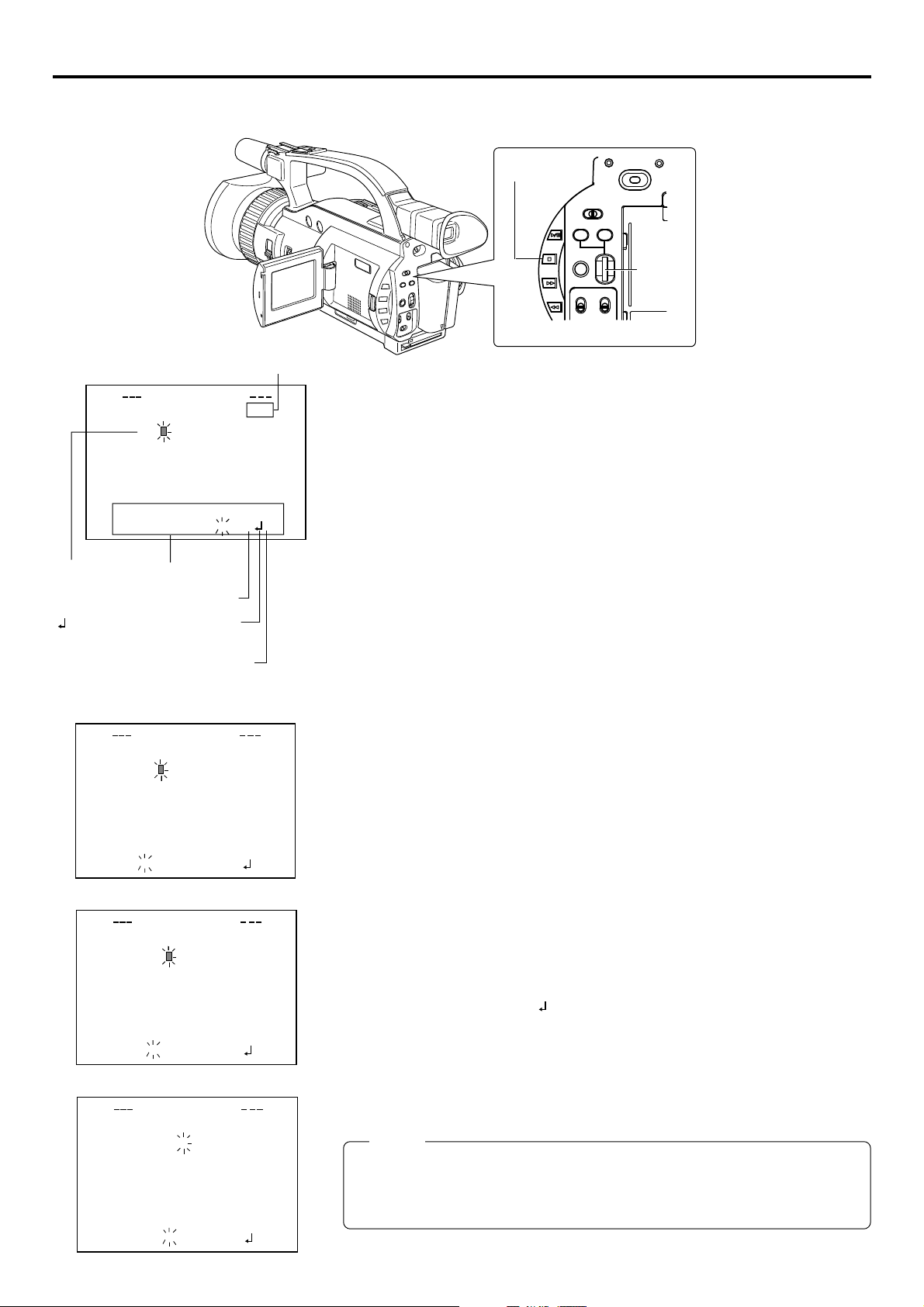
2
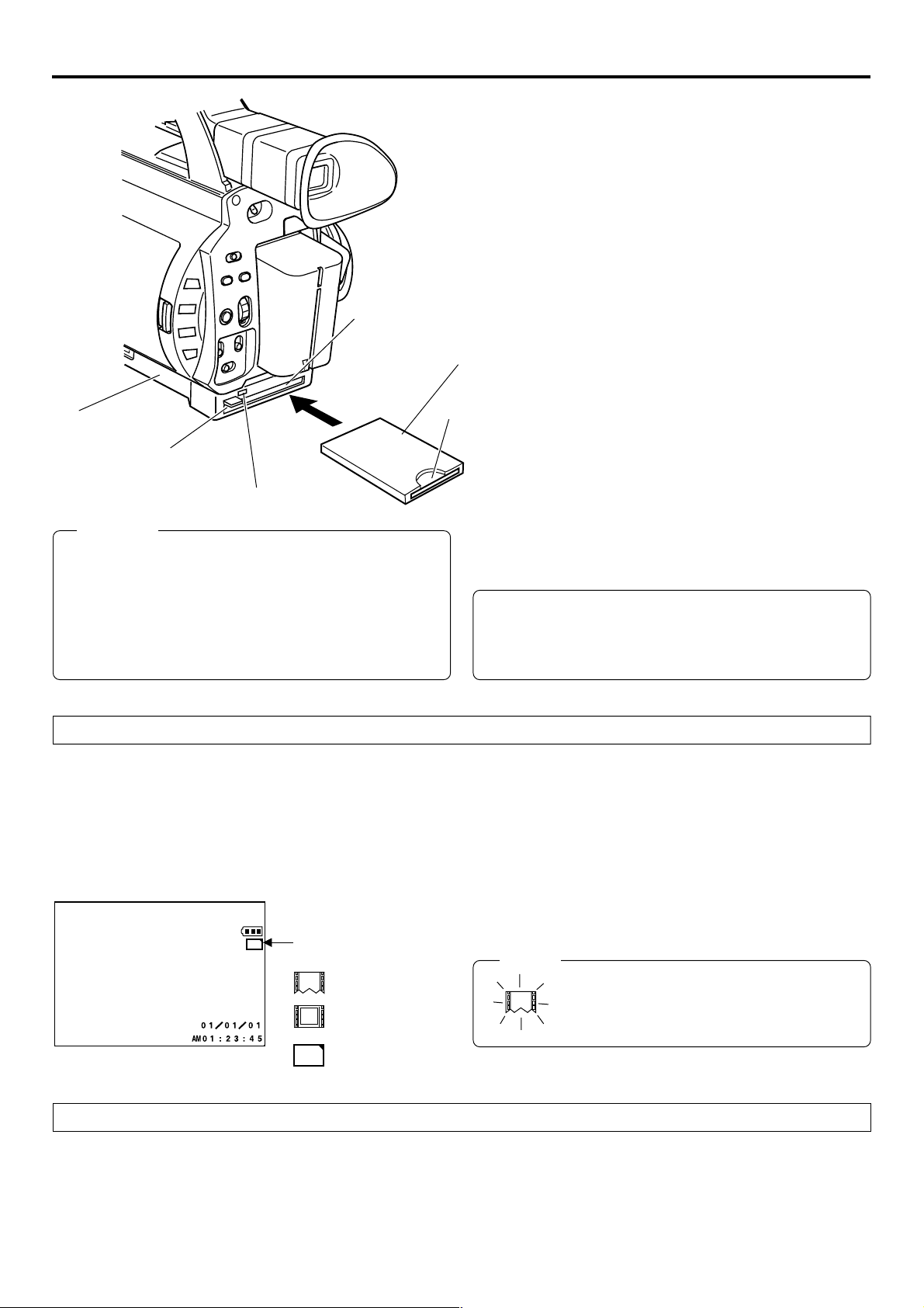
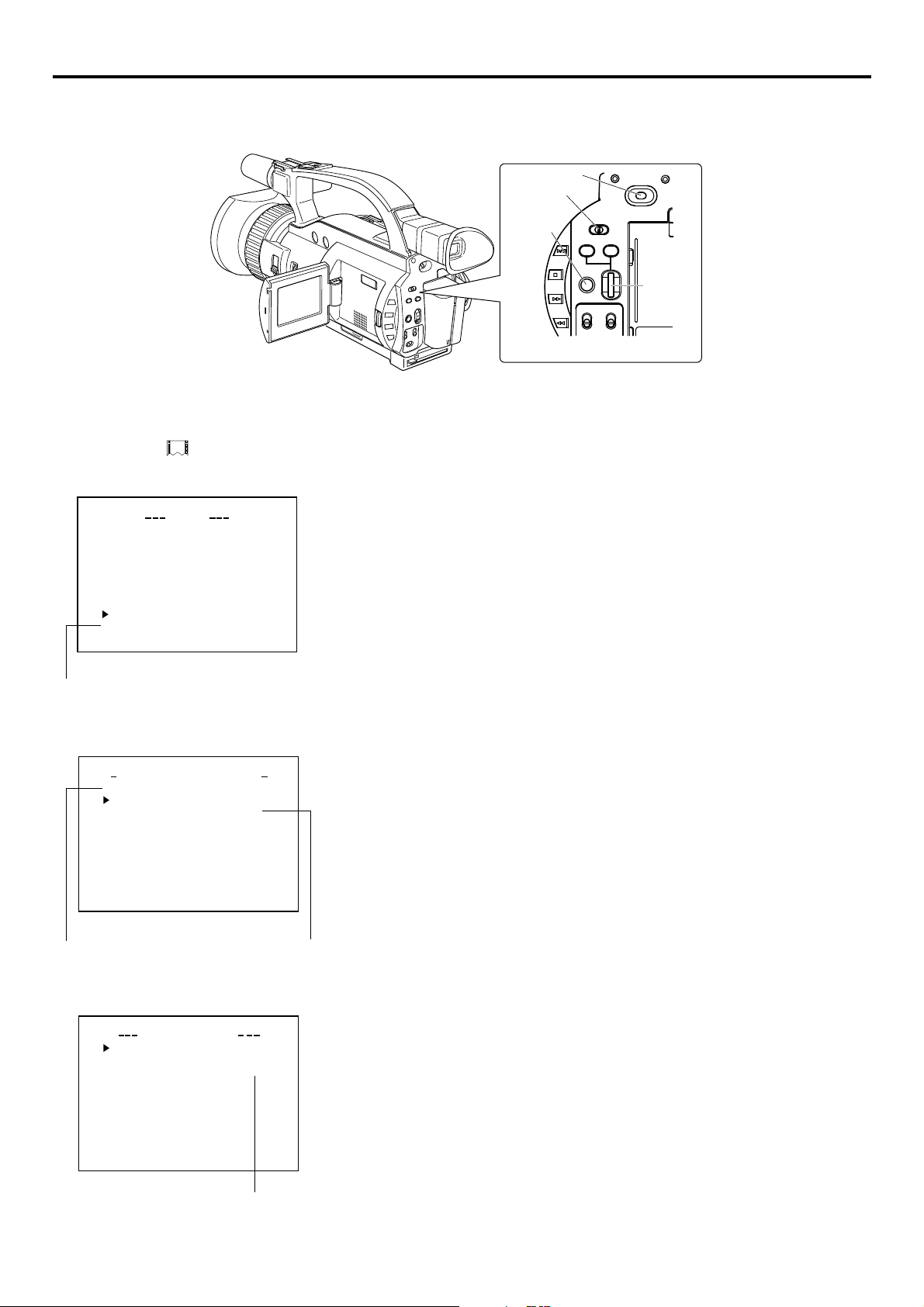
Introduction Inserting/removing CF memory card/LAN card
● The KA-DV300 accepts the following cards for which operation has
been confirmed: (As of August 2002)
Operating voltage 3.3 V
Current consumption Max. 500 mA
• Wired LAN-card
KA-DV300
EJECT button
ACCESS lamp
Card slot
CF Card adapter/LAN card
CF memory
card
US: EA2900-117 (Revision C) (Name of manufacturer: Socket
Communications, Inc)
Europe: EA2903-162 (Revision C) (Name of manufacturer: Socket
Communications, Inc)
Asia: EA2906-194 (Revision C) (Name of manufacturer: Socket
Communications, Inc)
* Revision indicated on the upper right of package production label.
• Wireless LAN-card
TEW-201PC
TEW-202CF
TEW-PC16 (firmware version 0.8.3 or later) (Name of manufacturer:
TRENDware)
WCF11 (Name of manufacturer: LINKSYS)
• CF (Compact Flash) card
SDCFB-16 ~ SDCFB-256 (Name of manufacturer: SanDisk)
*1: Use PCMCIA card TYPE 1 or TYPE 2 adapter
*2: Use PCMCIA card TYPE 2 adapter
*1
*1
*1
*2
*1
Caution
● Make sure the power of GY-DV300 is off when inserting/
removing a CF memory card/LAN card. Inserting/removing
a card with the unit power on may damage the data storage
section of the CF memory card or the card itself.
● Do not use the wireless LAN card continuously for more
than 48 hours.
Inserting card
1.
Turn off the GY-DV300 power.
2.
Insert a card into the KA-DV300 card slot.
3.
Turn on the GY-DV300 power.
LCD screen
C
F
Card status display
: No card
: LAN card
e
For the latest operational check card, visit the website below
or contact your JVC dealer.
http://www.jvc-victor.co.jp/english/pro/prodv/
● Card status according to the inserted card type is displayed on
the LCD screen/viewfinder screen. (☞ page 4)
Memo
When turning the power on, the card status
display shown on left will flash during initialization.
: CF memory card
C
F
Removing card
\ Check to make sure the ACCESS lamp of KA-DV300 is off.
The ACCESS lamp will light when the card is in operation.
1.
Turn off the GY-DV300 power.
2.
Press the EJECT button of KA-DV300 and remove the card.
3
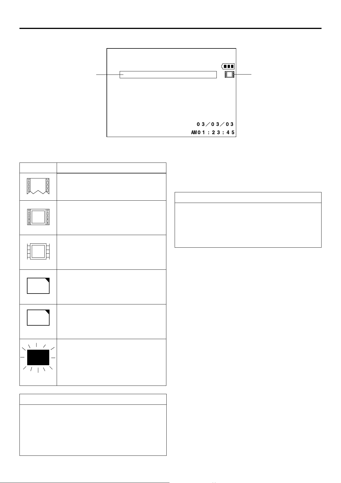
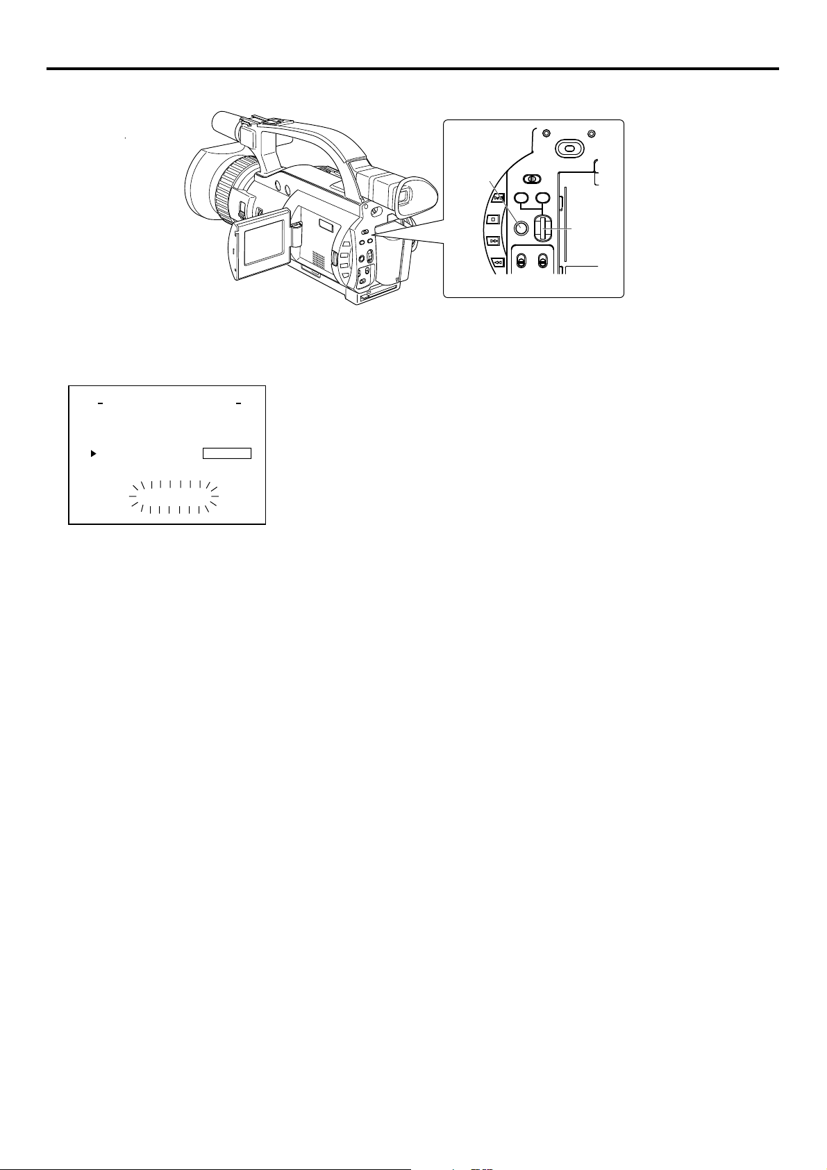
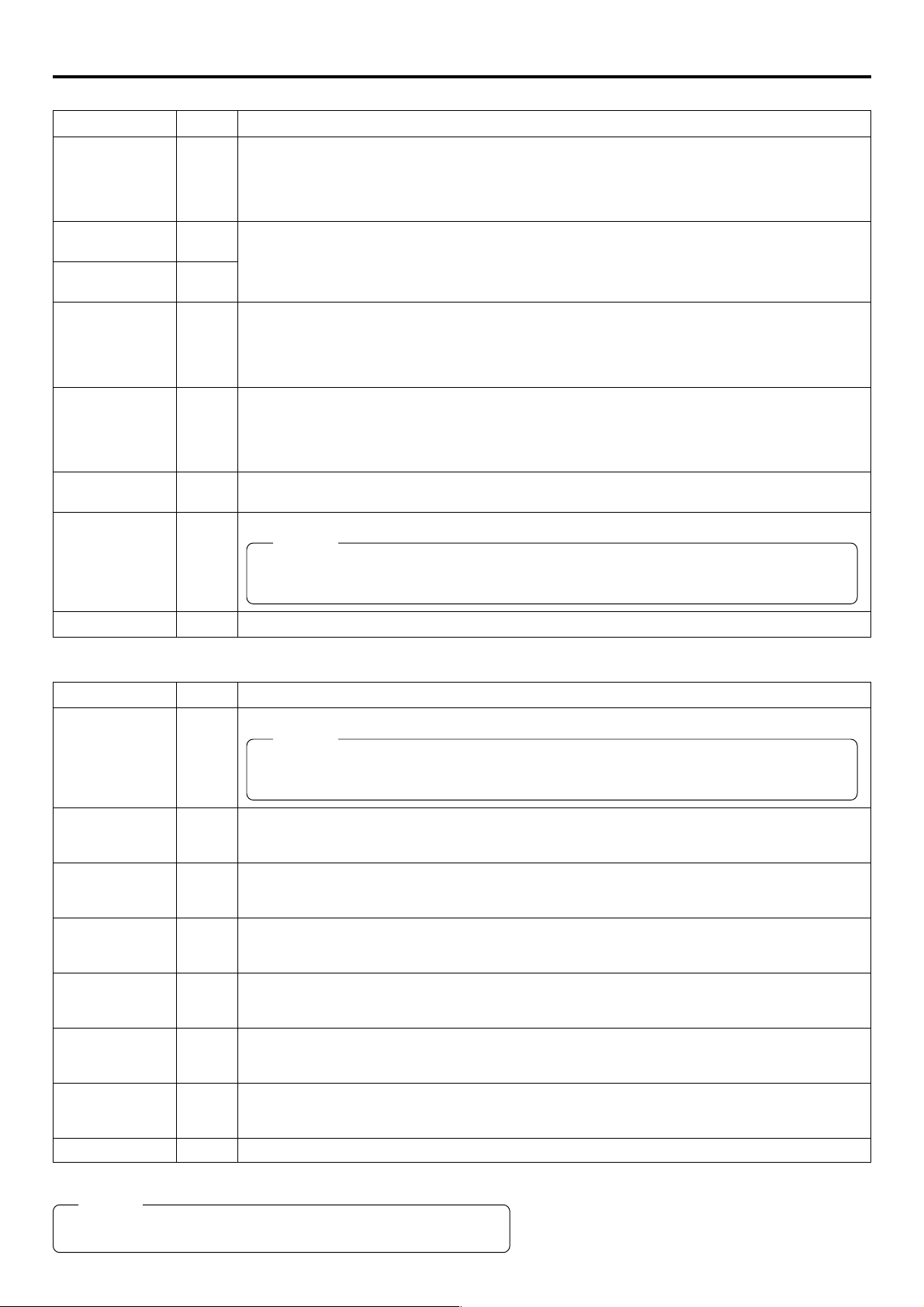
Introduction LCD screen/viewfinder screen
Information from Network Pack KA-DV300 is displayed on the GY-DV300 LCD screen/viewfinder screen.
qCard status displays
Display
No card is inserted in Network Pack.
Flashing display during initialization (after
power on).
LAN card is inserted in Network Pack.
e
(White display)
Video/audio data is being sent from LAN
e
card.
w
Description
CF FULL!
wCF Memory card warning display
Displays CF memory card status and system errors.
* For details concerning warning displays, see page 46.
e
When inputting the 44.1kHz sampling audio signal
This unit is not compatible with audio sampling frequency of
44.1kHz. When playing back a tape recorded with audio of
44.1kHz on GY-DV300 or when inputting audio in the 44.1kHz
mode into the DV terminal, the audio will be processed as muted
sound. However,the video will be processed as normal.
q
(Red display)
CF memory card is inserted in Network Pack.
C
F
(White display)
CF memory card is being recorded with data.
C
F
(Red display)
Card is inserted in Network Pack but transmission is not available.
X
Flashing display
Receiving Level Indicator of Wireless LAN
If you are using wirelss LAN card that can detect receiving level,
receiving level indicator is shown next to the card status information on LCD of your camcorder. The indicator shows value
from 5 to 0, 5 means maximum level and 0 means minimum
level. (The indicator is for reference. The value does not guarantee communication.)
There is possibility of unit malfunction.
Contact your nearest JVC dealer.
4
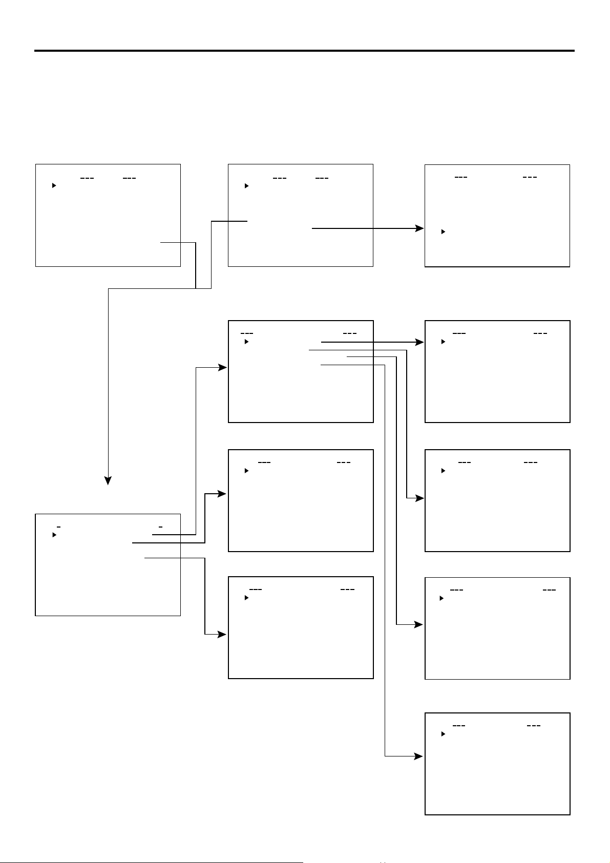
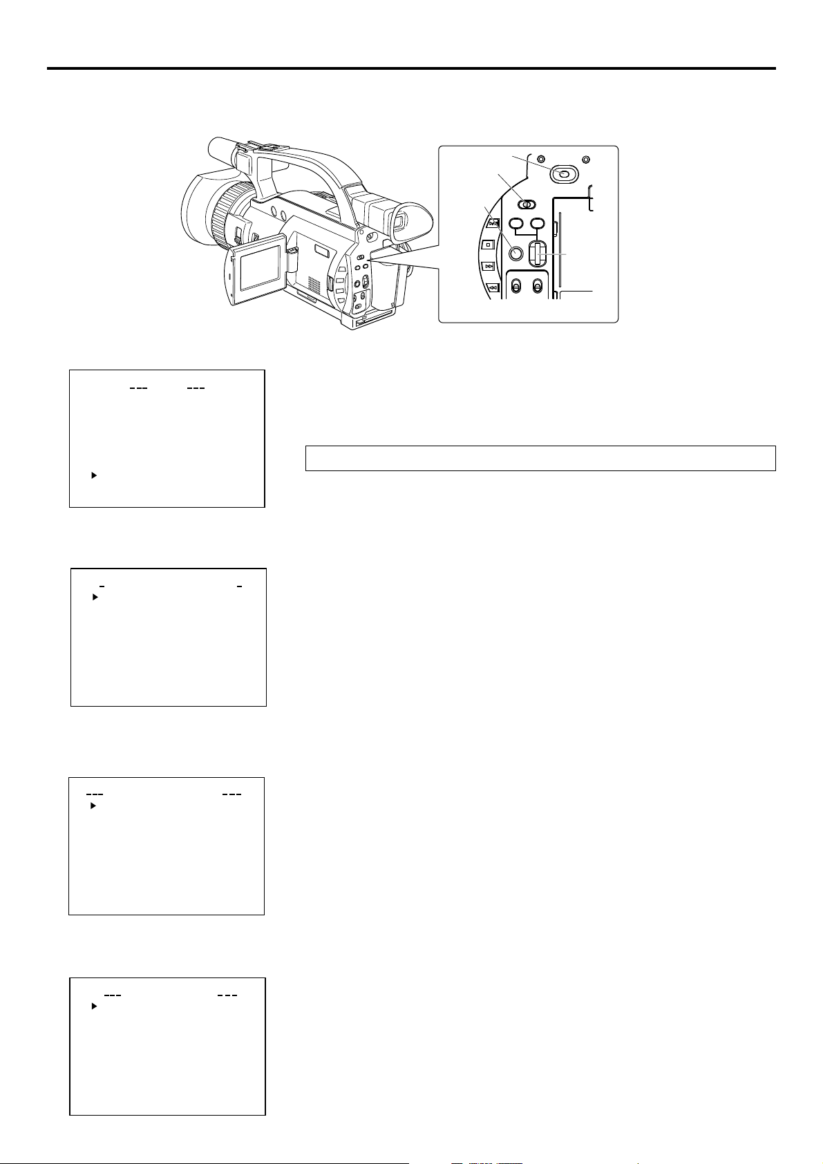
Menu screen Menu screen structure
When attaching Network Pack KA-Dv300 to DV Camcorder GY-DV300, NETWORK PACK CONFIG menu and MOVIE CLIP menu are
added to the GY-DV300 TOP MENU screen.
MODE switch: When CAM-A
or CAM-B is selected
TOP MENU screen
MO D E
EARPHONE L
SYSTEMSET ..
DISPLAYSETE..
CAME RASET [ CVAE-M
OPERATONI[CA-MA .
CLOC K/
MENU ALLRESET
NETWORKPACKCONFIG
EXIT
MENU
..
C
T
M
L10
]
A.
]
C
AN ALU
.
.
MODE switch:
VTR is selected
TOP MENU screen
VTRSET ..
SYSTEMSET ..
DISPLAYSET . .
CLOC K /
MENU ALLRESET
NETWORKPACKCONFIG
OE
M
VI CLIP
ELANC
..
EXIT
NETWORK MAIN SETUP menu screen
NETWORK SETUP . .
PORT SETUP . .
WI RELESS LAN SETUP . .
SERVER SE TUP . .
PAGE BACK
MENU
..
T
C
..
MA I
N
ELANC
C
..
UP
S
MOVIE CLIP list screen
(☞ page 23)
L
mc
00 5.0asf WR/
02 03/02/
00 6.0asf WR/
mc
02 03/02/
00 7.0asf WR/
mc
02 03/02/
00 8.0asf WR/
mc
02 03/02/
PAGE BACK
IEOVMCIP
09 0 0:00:
09 3 0:25:
10 1 0:55:
11 0 0:00:
* Example display when there are clip
files in the CF memory card
NETWORK SETUP menu screen
..
..
UPWOETNRK ET
S
FOF
HOS T NAME . .
DHCP
IP ADDRESS
SUB
PAGE BACK
NEXT PAGE
WOETNRKET
NET M SAK
..GAT
EWAY
NETWORK PACK CONFIG
menu screen
TSE P . .U
P
C
ON
P
TSE P . .U
F
RGI
T
ACNLE
C
ORTWENKACK
M
Pundr8)e
MA I N
NE T WOR K TSE P .U
ENCODE
MPE G R EC
MOV I ECLI
MENU R ES E T
PAGE BACK
(
W
IG
.
ENCODE SETUP menu screen
FRAME SIZE 320x24
BI T RATE 384kb/
MAX F RAME R A T E M I D
STREAM TYPE for WMP
PAGE BACK
ODNCEEET
UP
S
0
s
MOVIE CLIP SETUP menu screen
DELETE ALL CANCE
FORMAT CANCE
PLAY MODE REPEA
PAGE BACK
IEOVMCLIPET
UP
S
L
L
T
PORT SETUP menu screen
S
TORPET
H T T P for WE B Browser . .
H T T P for Media player. .
R T S P for Streamproducer .
R T S P for QuickTime . .
PAGE BACK
UP
.
WIRELESS LAN SETUP menu screen
AD . HOC . MODE ........OF F ..
Primary E SS . ID .
Secondary
Country
CH ................. H .
ESS ID
SETUP. WI RELESS . LAN .
. .......
.......
USA.............. ...
10C
2CHWE P .KEY . . .......... ..
OFFLEAP ............... ..
2CHPAGE . BACK .......... ..
....
....
...
.
SERVER SETUP menu screen
S
SETUP ON WEB OFF
LEAP USER NAME . .
LEAP PASS
HTTP USER NAME . .
HTTP PASSWORD . .
FTP USER NAME. .
FT P PASSWORD . .
PAGE BACK
VEERSRET
WOR D
UP
..
5

Menu screen NETWORK PACK CONFIG menu screen items
䢇 indicates default factory setting.
Item
NETWORK MAIN
SETUP
ENCODE SETUP
FRAME SIZE
VIDEO RATE
MAX FRAME
RATE
Setting
䢇320 × 240
160 × 120
56K
128K
256K
䢇384K
512K
MAX
䢇MID
MIN
BIT RATE
(bps)
512K
384K
256K
Description
Displays menu screen for network related settings. (☞ page 11)
Displays menu screen for setting video and audio compressions.
Sets the video compression size.
320 × 240: Sets the image size to 320 × 240 pixels. (CIF)
160 × 120: Sets the image size to 160 × 120 pixels. (QCIF)
(1/4 image size of CIF.)
Sets streaming speed (bps).
56K: MPEG4 24 kbps G726 16 kbps
128K: MPEG4 104 kbps G726 16 kbps
256K: MPEG4 232 kbps G726 24 kbps
384K: MPEG4 352 kbps G726 32 kbps
512K: MPEG4 472 kbps G726 40 kbps
Sets the frame rate per second. Settings are as shown below.
FRAME SIZE
320 × 240 160 × 120
MAX MID MIN MAX MID MIN
NTSC 15 10 7.5 30 15 10
PAL 12.5 5 5 25 12.5 12.5
NTSC 15 10 7.5 30 15 10
PAL 12.5 5 5 25 12.5 5
NTSC 15 7.5 5 30 15 7.5
PAL 12.5 5 5 25 12.5 5
BIT RATE
(bps)
128K
56K
* The frame rates shown in the table are not
guaranteed values.
NTSC 7.5 5 3 15 10 7.5
PAL 5 5 1 12.5 12.5 5
NTSC 3 1 1 10 7.5 5
PAL 1 1 1 12.5 5 5
FRAME SIZE
320 × 240 160 × 120
MAX MID MIN MAX MID MIN
STREAM TYPE
PAGE BACK
MPEG REC
䢇for WMP
for QT
䢇TRIG
SPLIT
OFF
Sets the player for stream playback.
for WMP: MediaPlayer, Streamproducer
for QT : Quick Time
Memo
● No sound will be heard when playing back using QuickTime while in the WMP mode.
● No sound will be heard when playing back using Media Player while in the QT mode.
● Set to WMP mode when recording to CF memory card.
Pressing the SELECT dial returns to the NETWORK PACK CONFIG menu screen.
Selects the operation method for recording video data to a CF memory card or sending data
to a remote media from a LAN card.
TRIG: Pressing the REC START/STOP button of GY-DV300 starts operation. Use this set-
ting when simultaneously recording to a DV tape.
SPLIT: Use this setting when recording or transferring with CF memory card or LAN card
only. Operation starts when pressing the SELECT dial of GY-DV300.
OFF: Recording will not be made to the CF memory card and streaming data from the
LAN card will not be recorded/sent to the PC even when pressing the REC START/
STOP button or the SELECT dial of GY-DV300.
→
OVER
6

Menu screen NETWORK PACK CONFIG menu screen items
Item
MOVIE CLIP SETUP
DELETE ALL
FORMAT
PLAY MODE
PAGE BACK
MENU RESET
PAGE BACK
Setting
䢇CANCEL
EXECUTE
䢇CANCEL
EXECUTE
OFF
REPEAT 1
䢇REPEAT
䢇CANCEL
EXECUTE
Description
Displays the menu screen for CF memory card related settings such as formatting or deleting all recorded clip files.
Selecting EXECUTE and pressing the SELECT dial deletes all clip files on the CF memory
card.
Protected clip files are not deleted.
Selecting EXECUTE and pressing the SELECT dial starts formatting the card.
All recorded clips are erased.
Playback is performed from the specified clip file to the latest clip file and pauses at the
specified clip file.
Specified clip file is played backed 3 times.
Playback is performed 3 times from the specified clip file to the latest clip file.
Pressing the SELECT dial returns to the NETWORK PACK CONFIG menu screen.
Selecting EXECUTE and pressing the SELECT dial returns NETWORK PACK CONFIG
menu screen settings to the original factory settings.
Pressing the SELECT dial returns to the TOP MENU screen.
7
Menu screen Setting the NETWORK PACK CONFIG menu screen
Menu screen settings can be made regardless of whether a card is inserted. Settings will be stored in the KA-DV300 memory even
when turning the power off.
● The NETWORK PACK CONFIG menu
screen will not appear during card initial-
ization (flashing
MO D E
EARPHO EN L LVEE 01
SYST EM SET ..
DISPLAY SET. .
CAMERA SE T [ C A -MA ..
OPERAT I ON [ CA -MA . .]
CLOC K/ TC. .
MENU A C E LANC
NETWORKPACKCONFIG
EXIT
Cursor
NETWORK PACK CONFIG
NE T WOR K I N S ETUP . .
ENCODE SE TUP
MPEG R EC
MOV I ECLI
MENU RE SE T CA NCEL
PAGE BACK
(WMP under 8)
TOP MENU screen
display).
MENU
LL RESET
menu screen
ORTWENKACK
MA
PS
MAN ALU
]
PONCIGF
..
T
..
ETUP
RGI
..
POWER switch
MODE switch
MENU
button
BAR
AW
FWD
REV
CAM-A
GAIN
MENU
MODE
CAM-B
SHUTTER
VTR
OFF
POWER
ON
SELECT
dial
<GY-DV300 rear panel>
\ Settings are made by viewing the LCD screen or viewfinder screen.
If OUTPUT CHAR of the DISPLAY [2/2] menu screen is set to MIX, the menu
screen also appears on the monitor screen connected to the VIDEO OUT or Y/C
connector.
1.
Set the POWER switch to ON.
2.
Set the MODE switch.
● Set to “CAM-A” or “CAM-B” when shooting a video.
● Set to “VTR” for VTR playback, clip file playback or DV signal recording.
3.
Press the MENU button for about 1 seconds. The TOP MENU screen appears.
4.
Turn the SELECT dial, move the cursor (t) to NETWORK PACK CONFIG and
press the SELECT dial.
● The NETWORK PACK CONFIG menu screen appears.
5.
Select the item to set.
Turn the SELECT dial, move the cursor to the desired item to set and press the
SELECT dial.
● The selected menu screen appears.
● When selecting MPEG REC or MENU RESET, the setting area flashes and the
setting can be changed. Set the item according to step 7.
● When selecting NETWORK MAIN SETUP, the network related setting screen
appears. (☞ page 10)
NETWORK MAIN SETUP
menu screen (☞ page 10)
ODNCEEET
SIZE 0 x24032
FRAME
BI T ARTE
MAX F RAMME
ST REA YTPE
PAGE BACK
6.
Select an item within the menu screen.
Turn the SELECT dial, move the cursor (t) to the desired item to set and press
the SELECT dial.
Setting
● The setting area flashes and the setting can be changed.
7.
Change the setting.
Turn the SELECT dial to change the setting and press the SELECT dial.
P
S
U
4 kb/s38
f
IDM
or
PWM
AR
TE
● Flashing of the setting area stops and the new setting is confirmed.
\ When changing multiple settings, repeat steps 6 and 7 above.
8.
Return to the TOP MENU screen.
Turn the SELECT dial, move the cursor (t) to PAGE BACK and press the SE-
LECT dial.
9.
When quitting menu screen setting and returning to the normal screen, perform
one of the following operations.
Setting
● Press the MENU button.
● Move the cursor (t) to EXIT in the TOP MENU screen and press the SELECT
dial.
8
Menu screen
Returning the NETWORK PACK CONFIG menu screen to factory settings
POWER
OFF
ON
AW
FWD
BAR
MODE
CAM-B
VTR
CAM-A
GAIN
SHUTTER
MENU
SELECT
dial
REV
MENU
button
<GY-DV300 rear panel>
NETWORK PACK CONFIG
menu screen
ORTWENKACK
NE T WOR K T . .
ENCODE SE T
MPE G R EC
MOV I ECLI
MENU
PAGE BACK
M
Pundr8)e
(
W
PONCIGF
SE
AI N
M
PPS
RESET EXECUTE
MENU RESET
U
..
P
U
ET
RGI
T
..
P
U
..
1.
Press the MENU button to display the TOP MENU screen.
2.
Check to see that the card status display has changed from a flashing to constant
display.
3.
Turn the SELECT dial to select NETWORK PACK CONFIG and press the SE-
LECT dial.
● The NETWORK PACK CONFIG menu screen appears.
4.
Turn the SELECT dial to set MENU RESET to “EXECUTE” and press the SELECT
dial.
● When resetting the menu, “MENU RESET..” will appear at the bottom of the
screen for about 5 seconds.
● The NETWORK PACK CONFIG menu screen settings will return to the factory
settings.
9
Network settings Setting the NETWORK MAIN SETUP menu screen
When using a LAN card, network related settings for KA-DV300 are made using NETWORK MAIN SETUP of the NETWORK PACK
CONFIG menu. Settings will be stored in the KA-DV300 memory even when turning the power off.
TOP MENU screen
MO D E
EARHON LE EV
SYSTEMSET ..
DISPLAY
CAME RASET [ CA -MA0.
OPERAT
OCK
L
C
MENU ALLRESET
NETWORKPACKCONFIG
EXIT
MENU
E
S
ET. .
O
I
N[CA-MA
C
T
..
/
L1
AN ALU
M
]
.
]
.
.
ELANC
C
..
NETWORK PACK CONFIG
menu screen
ORTWENKACK
PONCIGF
T..
SE
P
AI N
NE T WOR K
ENCODE
MPE G R EC
MOV I ECLI
MENU R ES E T C AN CE L
PAGE B
(WMPnde
M
SET
P
CK
A
u
r
U
P
..
U
S
8
ET
)
RGI
T
..
P
U
NETWORK MAIN SETUP
menu screen
MA I
WOETNRK ET
WOETNRK
ETSUP
S
SLWI RELE
R
ETSUP
..
A
ETSUP
PORT
SNERVE
PAGE BACK
N
..
..
S
ETSUP
UP
..
POWER switch
MODE
switch
MENU
button
BAR
AW
FWD
REV
CAM-A
GAIN
MENU
MODE
CAM-B
SHUTTER
VTR
OFF
POWER
ON
SELECT
dial
<GY-DV300 rear panel>
\ Settings are made by viewing the LCD screen or viewfinder screen.
If OUTPUT CHAR of the DISPLAY [2/2] menu screen is set to MIX, the menu screen
also appears on the monitor screen connected to the VIDEO OUT or Y/C connector.
Display the NETWORK SETUP menu screen
1.
Turn on the GY-DV300 power.
2.
Check to see that the card status display has changed from a flashing to constant
display.
3.
Press the MENU button to display the TOP MENU screen.
4.
Turn the SELECT dial, move the cursor (t) to NETWORK PACK CONFIG and
press the SELECT dial.
● The NETWORK PACK CONFIG menu screen appears.
5.
Turn the SELECT dial, move the cursor (t) to NETWORK MAIN SETUP and
press the SELECT dial.
● The NETWORK MAIN SETUP menu screen will appear.
The NETWORK MAIN SETUP menu screen is structured by 4 screens.
NETWORK SETUP
PORT SETUP
WIRELESS LAN SETUP
SERVER SETUP
6.
Turn the SELECT dial, move the cursor (t) to SETUP and press the SELECT
dial.
● The selected SETUP screen appears.
Items with “..” at the end of the name are set in the INPUT screen.
NETWORK SETUP
menu screen
HOS T NAME . .
DHC P
IP ADDRESS
SUB
NE X T PAGE
PAGE BACK
WOETNRK
..
K
Y
..GATEWA
7.
To return to the NETWORK MAIN SETUP menu screen, select PAGE BACK and
press the SELECT dial.
8.
To return to the normal screen after completing setting, perform one of the follow-
ETSUP
FOF
..NET M SA
ing operations.
● Press the MENU button
● Select PAGE BACK to return to the TOP MENU screen. Select EXIT in the TOP
MENU screen and press the SELECT dial.
10
Network settings NETWORK MAIN SETUP menu screen items
NETWORK SETUP menu screen 䢇indicates default factory setting.
Item
HOST NAME
DHCP
IP ADDRESS
SUBNET
GATE WAY
PAGE BACK
MASK
Setting
䢇OFF
ON
Description
Displays the host name input setting screen. (4 ~ 64 alphanumerical characters)
[Factory setting: none]
Select whether DHCP server is used.
OFF: Use this setting when using LAN connection rather than DHCP.
When this setting is used, IP ADDRESS and SUBNET MASK, GATEWAY must also be set.
ON: Use this setting when using DHCP connection.
When using this setting, IP ADDRESS and
* When DHCP is set to ON, WLAN ADHOC MODE cannot be set to AHDM or IBSS.
Displays the IP address setting screen.
When using LAN connection with DHCP set to OFF, this setting is required. Set a unique IP address.
IP ADDRESS setting is not available when DHCP is set to ON.
[Factory setting] 192.168.100.101]
Displays the subnet mask input screen.
This setting is required when using LAN connection with DHCP set to OFF.
SUBNET
[Factory setting: 255.255.255.000]
Displays the gateway address input screen.
GATEWAY setting is not available when DHCP is set to ON.
[Factory setting: 192.168.100.254]
Pressing the SELECT dial returns to the NETWORK MAIN SETUP menu screen.
MASK setting is not available if DHCP is set to ON.
SUBNET
MASK, GATEWAY are automatically set.
PORT SETUP menu screen
Item
HTTP for
WEB Browser
HTTP for
Mediaplayer
RTSP for
Streamproducer
RTSP for
Quick Time
PAGE BACK
Setting
1
:
䢇80
:
32767
1
:
䢇8080
:
32767
1
:
䢇8554
:
32767
1
:
䢇554
:
32767
Description
The screen for setting RTSP and HTTP port numbers appears.
HTTP for Web Browser can be set with the Web browser HTTP port number and HTTP for
Mediaplayer can be set with the Mediaplayer HTTP port number. RTSP for Streamproducer can be
set with the Streamproducer RTSP port number and RTSP for Quick Time can be set with the Quick
Time RTSP port number.
Normally, the unit can be used without changing the factory settings.
If there are port restrictions for the LAN environment of your PC, consult your network administrator.
* When changing a port number, refer to “5-1. Connecting with Camcorder” of the “Streamproducer”
User’s Guide of the network distribution software to change settings.
* Do not use the same port numbers for RTSP and HTTP.
* When a port number is changed, switch the power of the GY-DV300 off once, and then switch it on
again.
Pressing the SELECT dial returns to the NETWORK SETUP menu screen.
→
OVER
11
Network settings NETWORK MAIN SETUP menu screen items
WIRELESS LAN SETUP menu screen 䢇indicates default factory setting.
Item
AD HOC MODE
Primary
ESS ID
Secondary
ESS ID
Country
CH
WEP KEY
LEAP
Setting
䢇OFF
AHDM
IBSS
NONE
NONE
䢇USA
EU
FRN
SPN
JPN
1CH
:
䢇10CH
:
14CH
ON
䢇OFF
Description
Wireless LAN setting
OFF: Use this setting when performing communication via access point.
AHODM/IBSS: Use this setting when performing communication in AD HOC mode with a PC con-
nected with a wireless LAN card. (☞page 16)
* When this item is set to AHDM or IBSS, DHCP cannot be set to ON.
Displays the wireless LAN ESS-ID input setting screen (Max. 32 alphanumerical characters)
Setting for the country using wireless LAN
USA: USA, EU: Europe, FRN: France, SPN: Spain, JPN: Japan
(Set according to operating environment.)
Wireless LAN channel setting
CH setting changes depending on the Country setting.
USA: 1 ~ 11CH, EU: 1 ~ 13CH, FRN: 10 ~ 13CH, SPN: 10, 11CH, JPN: 1 ~ 14CH
When encrypting data, set the WEP KEY (10 or 26 characters consisting or letters a ~ fandnumbers).
Must be compatible with access point authentication for the use of this item.
Set to ON when connecting a Cisco Systems wireless LAN device and using the LEAP function.
Memo
The LEAP function is exclusive to Cisco Systems wireless LAN devices. For details concerning
the LEAP function, see the instruction manual accompanying the wireless LAN device.
PAGE BACK
SERVER SETUP menu screen
Item
SETUP ON
WEB
LEAP USER
NAME
LEAP
PASSWORD
HTTP USER
NAME
HTTTP
PASSWORD
FTP USER
NAME
FTP
PASSWORD
PAGE BACK
Setting
ON
䢇OFF
Pressing the SELECT dial returns to the NETWORK MAIN SETUP menu screen.
Description
Set to ON when changing the USER NAME and PASSWORD from the Web.
Memo
If higher security is desired, set this function to OFF so that changes cannot be made from the
Web.
Displays the LEAP USER NAME input screen. (4 ~ 32 alphanumerical characters)
Set when using the LEAP function.
[Default setting: leap-user]
Displays the LEAP PASSWORD input screen. (4 ~ 32 alphanumerical characters)
Set when using the LEAP function.
[Default setting: ka-dv-jvc]
Displays the HTTP USER NAME input screen. (3 ~ 8 alphanumerical characters)
Set when connecting from the Web browser.
[Default setting: jvc]
Displays the HTTP PASSWORD input screen. (4 ~ 8 alphanumerical characters)
Set when connecting from the Web browser.
[Default setting: ka-dv300]
Displays the FTP USER NAME input screen. (3 ~ 8 alphanumerical characters)
Used when uploading USER PAGE.
[Default setting: ftp-user]
Displays the FTP PASSWORD input screen. (4 ~ 8 alphanumerical characters)
Used when uploading USER PAGE.
[Default setting: ka-dv]
Pressing the SELECT dial returns to the NETWORK MAIN SETUP menu screen.
Memo
For details concerning user name and password settings, see page 13.
12

Network settings Setting user names and passwords
\ Changing the user name
When changing the HTTP USER NAME or FTP USER NAME, “NEXT STEP SET PASSWORD” will appear on the screen and the
PASSWORD menu screen is displayed.
When input is canceled in the PASSWORD menu screen, the user name will also be canceled.
It is possible to change only the password.
When changing the LEAP USER NAME setting, the PASSWORD menu screen will not appear automatically.
\ Setting passwords
Set LEAP, HTTP and FTP PASSWORD using the procedure shown below.
1.
First, enter the currently used password when “ENTER OLD PASSWORD” is displayed.
2.
Next, enter the new password when “ENTER NEW PASSWORD” is displayed.
3.
Lastly, enter the new password again when “CONFIRM NEW PASSWORD” is displayed.
Caution
● Do not forget to take a memo of the password. The password cannot be redisplayed.
● Each character input on the PASSWORD menu screen is hidden using asterisks (*).
● When performing MENU RESET, the unit will return the default factory settings.
13
Network settings Making network related settings
Network related settings are made in the individual input setting screens.
Here, HTTP USER NAME is set as an example. Other settings are also made in the same manner.
HTTP USER NAME input setting screen
Currently inputted number of characters/
max.number of characters
RSEU
NAMETTPH
jvc
Setting area
BS:
Backspace (
abc d e fghijklmnopqrst uv
wx y z 0 12345 6 7 8 9
Character
selection area
delete previous character
_
: The set text is confirmed and
returns to the previous screen.
6: The set text is canceled and
returns to the previous screen.
MODE
CAM-B
SHUTTER
VTR
OFF
POWER
ON
SELECT
dial
STOP button
BAR
AW
FWD
REV
CAM-A
GAIN
MENU
<GY-DV300 rear panel>
3/8
Example: Changing HTTP USER NAME from jvc to jvc-1234
\ Select HTTP USER NAME in the SERVER SETUP menu screen and press the
SELECT dial.
● The USER NAME input setting screen appears.
1.
6
¯
BSA
.
Characters are selected from the character selection area on the bottom of the
screen.
Turn the SELECT dial to flash “_” in the character selection area and press the
SELECT dial.
)
● The setting changes to “jvc_” and the following digit of the setting area flashes.
2.
Turn the SELECT dial to select “1” in the character selection area and press the
SELECT. dial.
● The setting changes to “jvc_1” and the following digit of the setting area flashes.
RSEUPTTHNA
EM
4/8
_
jvc
abc d e fghi j klmnopqrst uv
wx y z 0 12345 6 7 8 9
_
jvc 1
abc d e fghi j klmnopqrst uv
wx y z 0 12345 6 7 8 9
_
jvc 1234
abc d e fghi j klmnopqrst uv
wx y z 0 12345 6 7 8 9
_
BSA
6
¯
.
RSEUPTTHNA
EM
5/8
_
BSA
6
¯
.
RSEUPTTHNA
EM
8/8
_
BSA
6
¯
.
3.
Repeat the above step to set “jvc_1234” in the setting area.
\ To delete or edit set characters, select “BS” within the character selection area and
press the SELECT dial.
The previous character will be deleted. The character on the left will be deleted each
time this operation is repeated.
\ When turning the SELECT dial while holding down the STOP button, the cursor will
move 5 characters at a time.
\ The currently inputted number of characters and the maximum number of characters
are displayed on the upper right of the screen.
\ To cancel a setting, select the “6” within the character selection area and press the
SELECT dial. The unit will return to the previous screen (SERVER SETUP menu
screen).
4.
When completed, select “ ” within the character selection area and press the
SELECT dial.
● When changing the HTTP USER NAME or FTP USER NAME, “NEXT STEP
SET PASSWORD” will appear on the screen and the PASSWORD menu screen
is displayed. Set the password using the procedure shown above.
Memo
When setting is completed for items other than HTTP USER NAME and FTP USER
NAME, the unit will return to the previous screen (NETWORK MAIN SETUP or
SERVER SETUP menu screen).
14
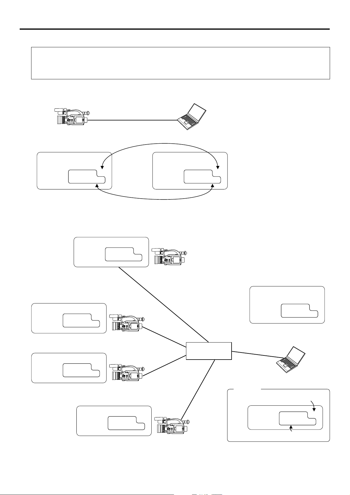
Network settings Detailed IP settings (LAN)
Example of IP address and subnet mast settings when using LAN is shown below.
●Operation is only guaranteed for Windows 2000, Windows XP Home Edition or Windows XP Professional.
●Internet Explorer 5.0 or later
●Windows Media Player 7.01 or later (WM9 is not supported.)
1. For 1:1 communication between PC and GY-DV300/KA-DV300
DHCP OFF
IP ADDRESS 192. 168. 100. 101
NETMASK 255. 255. 255. 000
10 BASE-T cross cable
Set a unique number to avoid doubling
PROXY SERVER NO USE
DHCP SERVER NO USE
IP ADDRESS 192. 168. 100. 100
NETMASK 255. 255. 255. 000
Set the same network group
* For the PC settings when using a LAN card,
refer to the instruction manual included with
the LAN card.
* Up to 3 clients can access at the same time.
2. For communication between PC and multiple GY-DV300/KA-DV300
DHCP OFF
IP ADDRESS 192. 168. 100. 101
NETMASK 255. 255. 255. 000
DHCP OFF
IP ADDRESS 192. 168. 100. 102
NETMASK 255. 255. 255. 000
DHCP OFF
IP ADDRESS 192. 168. 100. 103
NETMASK 255. 255. 255. 000
DHCP OFF
IP ADDRESS 192. 168. 100. 104
NETMASK 255. 255. 255. 000
PROXY SERVER NO USE
DHCP SERVER NO USE
IP ADDRESS 192. 168. 100. 100
NETMASK 255. 255. 255. 000
Hub
10 BASE-T straight cable
Caution
Set a unique number to avoid doubling
IP ADDRESS 192. 168. 100. XXX
NETMASK 255. 255. 255. 000
Set the same network group
15
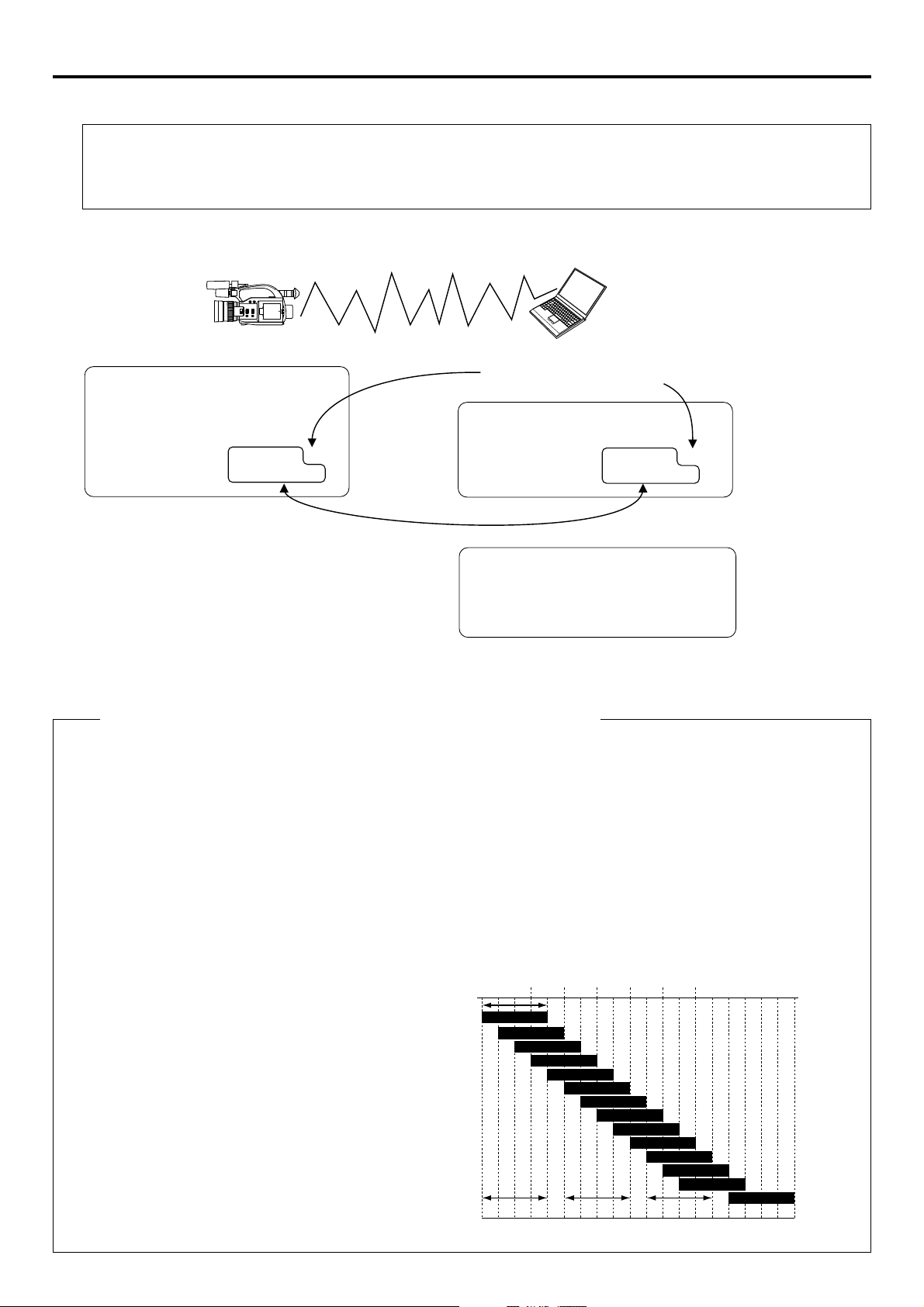
Network settings Detailed network settings (WLAN)
Example of network settings when using wireless LAN is shown below.
●Operation is only guaranteed for Windows 2000, Windows XP Home Edition or Windows XP Professional.
●Internet Explorer 5.0 or later
●Windows Media Player 7.01 or later (WM9 is not supported.)
1. For communication with PC without returning access point (Ad hoc mode)
* Do not perform encryption of the
wireless LAN.
Set a unique number to avoid doubling
DHCP OFF
WLAN AD HOC MODE ON
WLAN ESS ID abcdef
WLAN CH 2
IP ADDRESS 192. 168. 100. 101
NETMASK 255. 255. 255. 000
PROXY SERVER OFF
DHCP SERVER OFF
IP ADDRESS 192. 168. 100. 100
NETMASK 255. 255. 255. 000
Set the same network group
PC wireless LAN driver settings
NetworkType 802. 11 Ad Hoc Mode
ESS ID abcdef
Channel 2
Encryption Mode Open System
* For the PC settings when using a LAN card, refer to
the instruction manual included with the LAN card.
Cautionary items concerning Wireless LAN (WLAN)
● For the WLAN ESS ID, input the values of ESSID set in:
Ad hoc mode: PC of other party
Infrastructure: Access point
● WLAN AD HOC MODE
When IBSS is set, the NETWORK MODE setting of the wireless LAN card on the PC side must be set to 802.11 Adhoc.
When AHDM is set, the NETWORK MODE setting of the wireless LAN card on the PC side must be set to Adhoc. Depending on the LAN card on the PC side, only 802.11 Adhoc mode may be available.
● WLAN CH is the wireless frequency band used for communication. If there is an access point, adapter, etc., using the
same band in the proximity, there may be a hindrance in the communication and may reduce throughput or the quality of
communication. When setting, check the settings of surrounding access points, etc., to avoid doubling.
2417
2427
2437
2447
2457
11ch
2462
12ch
2467
2472 2484
13ch
14ch
Frequency bands (ISM bands) and channels
(IEEE803.11b standard)
N. America : FCC / 2.412~2.462GHz (11 channels)
Europe : CE ETSI / 2.412~2.472GHz (13 channels)
Japan : 2.412~2.4835GHz (14 channels)
France : 2.457~2.472GHz (4 channels)
Spain : 2.457~2.462GHz (2 channels)
Since adjacent channels causes signal
interference, channels are normally
spaced 5 channels apart.
(Set according to operating environment.)
Approx.
11MHz
2412
2422
2432
2442
1ch
2ch
3ch
4ch
5ch
6ch
7ch
8ch
9ch
1ch frequency band1ch frequency band 1ch frequency band11ch frequency band 1ch frequency band14ch frequency band6ch frequency band6ch frequency band
2452
10ch
Center
frequency
16
→
OVER
 Loading...