

Page 1
.
HD MEMORY CARD CAMERA RECORDER
JY-HM360AG
TIME CODE
This manual provides a brief explanation on
operating this camera recorder. For detailed
operation methods and camera settings,
please refer to the following Mobile User
Guide.
.
The specifications and appearance of this product are subject to changes for further improvement
without prior notice.
Please check the latest version of the INSTRUCTIONS from the following Mobile User Guide. You can
also download the PDF from the Mobile User Guide.
INSTRUCTIONS (BASIC)
Mobile User Guide
When you are outside, you can refer to the instructions from your Android phone or iPhone.
http://manual3.jvckenwood.com/pro/mobile/global/
You can view the Mobile User Guide using the browser on your Android phone or iPhone.
This product does not come with a battery pack.
When using a battery, please purchase the recommended battery pack (SSL-JVC50).
Please read the following before getting started:
Thank you for purchasing this JVC product.
Before operating this unit, please read the
instructions carefully to ensure the best
possible performance.
IM 1.00 B5A-1538-00
Page 2

2
Page 3

Safety Precautions
CAUTION:
The mains plug shall remain readily
operable.
Remove the mains plug immediately if
the camera functions abnormally.
WARNING:
The battery pack, the camera with
battery installed, and the remote control
with battery installed should not be
exposed to excessive heat such as direct
sunlight, fire or the like.
WARNING: TO PREVENT FIRE OR
SHOCK HAZARD, DO NOT
EXPOSE THIS UNIT TO RAIN OR
MOISTURE.
NOTES:
The rating plate and safety caution are
on the bottom and/or the back of the
main unit.
The serial number plate is on the
bottom of the unit.
The rating information and safety
caution of the AC adapter are on its
upper and lower sides.
Caution on Replaceable lithium
battery
The battery used in this device may
present a fire or chemical burn hazard if
mistreated.
Do not recharge, disassemble, heat
above 100°C or incinerate.
Replace battery with Panasonic, Sanyo,
Sony or Maxell CR2025.
Danger of explosion or risk of fire if the
battery is incorrectly replaced.
Dispose of used battery promptly.
Keep away from children.
Do not disassemble and do not dispose
of in fire.
When the equipment is installed in a
cabinet or on a shelf, make sure that it
has sufficient space on all sides to allow
for ventilation (10 cm or more on both
sides, on top and at the rear).
Do not block the ventilation holes.
(If the ventilation holes are blocked by a
newspaper, or cloth etc. the heat may not
be able to get out.)
No naked flame sources, such as lighted
candles, should be placed on the
apparatus.
When discarding batteries,
environmental problems must be
considered and the local rules or laws
governing the disposal of these batteries
must be followed strictly.
The apparatus shall not be exposed to
dripping or splashing and that no objects
filled with liquids, such as vases, shall be
placed on the apparatus.
Do not point the lens directly into the
sun. This can cause eye injuries, as well
as lead to the malfunctioning of internal
circuitry. There is also a risk of fire or
electric shock.
CAUTION!
The following notes concern possible
physical damage to this unit and to the
user.
Carrying or holding this unit by the LCD
monitor can result in dropping the unit,
or in a malfunction.
Do not use a tripod on unsteady or
unlevel surfaces. It could tip over,
causing serious damage to the unit.
CAUTION!
Connecting cables (Audio/Video, etc.) to
this unit and leaving it on top of the TV is
not recommended, as tripping on the
cables will cause the unit to fall, resulting
in damage.
.
Introduction
.
Safety Precautions
3
Page 4
CAUTIONS:
To prevent shock, do not open the
cabinet. No user serviceable parts
inside.
Refer servicing to qualified personnel.
When you are not using the AC
adapter for a long period of time, it is
recommended that you disconnect the
power cord from AC outlet.
CAUTION:
Where there are strong electromagnetic
waves or magnetism, for example near a
radio or TV transmitter, transformer,
motor, etc., the picture and the sound
may be disturbed. In such case, please
keep the apparatus away from the
sources of the disturbance.
CAUTION:
To avoid electric
shock or damage to
the unit, first firmly
insert the small end
of the power cord into the AC Adapter
until it is no longer wobbly, and then plug
the larger end of the power cord in to an
AC outlet.
The plastics packaging bags may cause
suffocation when they are covered over the
head. Tear them open, and keep them away
from the reach of infants and children by
ensuring that they are disposed of properly.
If this symbol is shown, it is only
valid in the European Union.
Battery Pack (sold separately)
The battery pack is a lithium-ion battery.
Before using the battery pack, be sure to
read the following cautions:
To avoid hazards
... do not burn.
... do not short-circuit the
terminals. Keep it away
from metallic objects
when not in use.
When transporting, carry the battery in
a plastic bag.
... do not modify or disassemble.
... do not expose the battery to
temperatures exceeding 60°C, as this
may cause the battery to overheat,
explode or catch fire.
... use only specified chargers.
Terminals
To prevent damage and prolong
service life
... do not subject to unnecessary shock.
... charge within the temperature range
of 10°C to 30°C. Cooler temperatures
require longer charging time, or in
some cases stop charging at all.
Warmer temperatures prevent
complete charging, or in some cases
stop charging at all.
... store in a cool, dry place. Extended
exposure to high temperatures will
increase natural discharge and
shorten service life.
... keep a 30% battery level if the
battery pack is not to be used for a
long period of time.
... remove from charger or powered unit
when not in use, as some machines
use current even when switched off.
... do not drop or subject to strong
impact.
Introduction
.
.
.
Safety Precautions
4
.
Page 5

Contents
Content of this manual
Introduction
Safety Precautions
Contents ............................................................ 5
Verifying the Accessories .................................. 5
Names of Parts .................................................. 6
............................................ 3
Preparations
Adjusting the Grip Belt ....................................... 9
Opening/Closing the Lens Cover ....................... 9
Attaching/Detaching the Hood ........................... 9
Using a Battery Pack (sold separately) ............ 10
Configuring the Initial Settings ......................... 11
Usable Cards ................................................... 13
Estimated Recordable Time of SD Cards ........ 13
Inserting an SD Card ....................................... 13
Shooting
Basic Shooting Procedures ............................. 16
Using Scene Select ......................................... 17
Miscellaneous Functions for Shooting and
Recording Methods ......................................... 19
Playback
Playing Recorded Clips ................................... 20
Connecting External Devices
Connecting External Monitor ........................... 21
Loading Clips to the PC ................................... 22
Others
Menu Screen Hierarchical Chart ..................... 23
Basic Operations in Menu Screen ................... 24
Display Screen ................................................ 25
Status Screen .................................................. 30
Troubleshooting .............................................. 31
Precautions for Proper Use ............................. 32
Specifications .................................................. 36
Software License Agreement .......................... 38
Important Notice concerning the Software ....... 39
Symbols used
Caution : Describes precautions concerning the
operation of this product.
Memo : Describes reference information, such as
functions and usage restrictions of this
product.
Verifying the Accessories
Verify that the following accessories are included
with the camera recorder before using.
Accessories
INSTRUCTIONS (BASIC) 1
AC Adapter 1
Power Cord 1
Introduction
Contents
5
Page 6
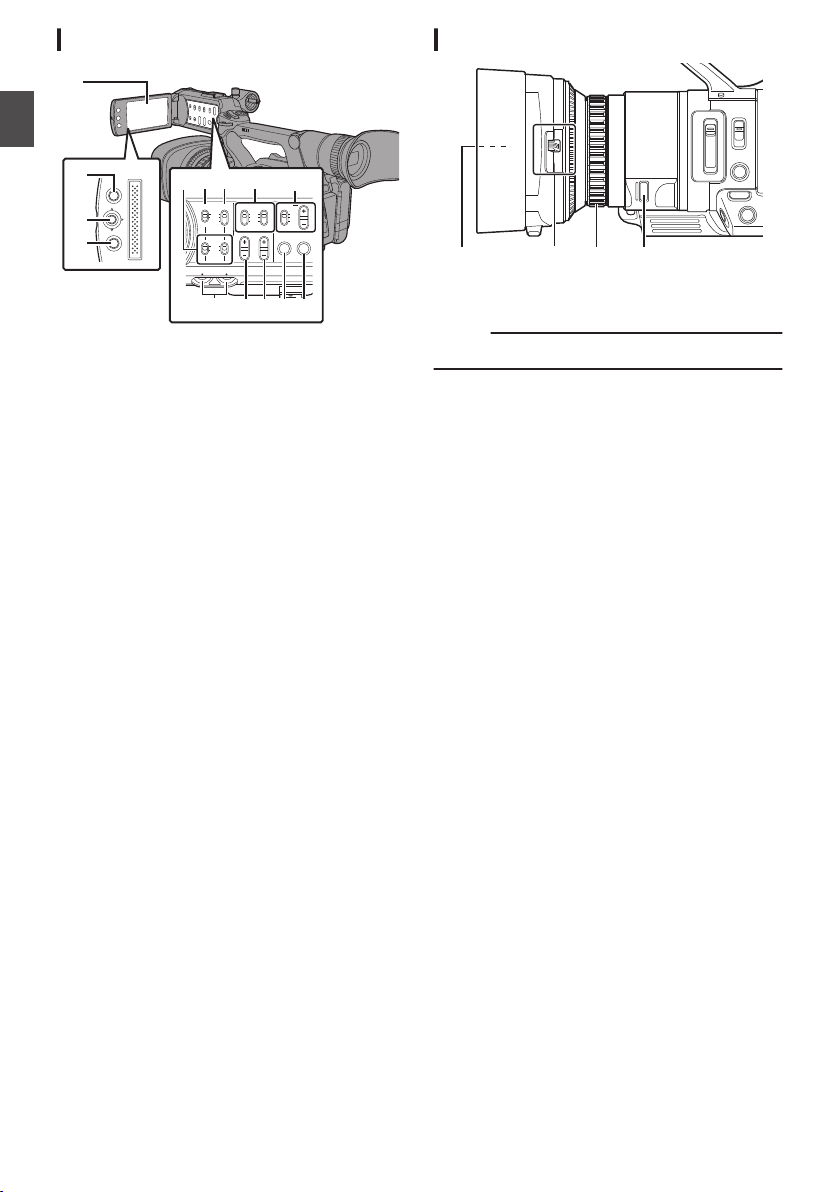
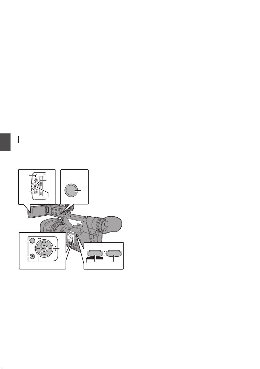
Names of Parts
FOCUS ZOOM
REC
I
J
K
E GDACBF
H
FIX VAR OFF
FOCUS ASSIST/1
OIS/2
LOLUX/3
MENU/THUMB
AE LEVEL
FOCUS
ND FILTER
1/64
1/16
1/4
OFF
POWER
MARKER/6
ZEBRA/5
AE LOCK/4
SHUTTER
WHT BAL
CANCEL
PUSH AUTO
IRIS
GAIN
FULL AUTO
PUSH AUTO
PRESET
B
L
M
H
A
ON
OFF
ON
MANU
∞
MODE
OFF
SLOT
A/B
TIME CODE
AUTO
Bottom
AUX
INPUT2
INPUT1
DEVICE
AV
A
BATT.RELEASE
POWER
/CHG
B
HDMI
REMOTE
DC
REC
W
T
REC
HOLD
IN
OUT
TC
L
M
N
O
d
R
S T
X
Z
a
b
c
Q
P
U
V
Y
W
Introduction
.
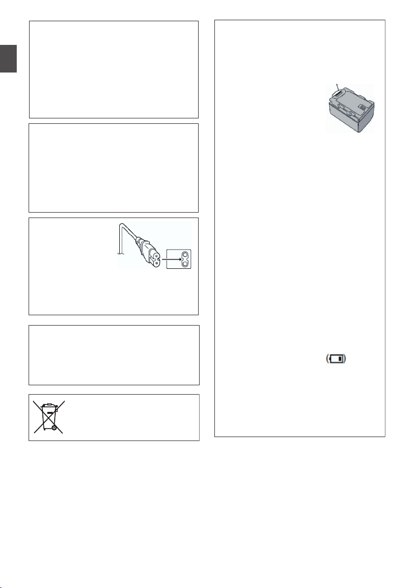
A
Built-in Microphone
B
Tally Lamp
C
Microphone Holder
D
Microphone Holder Lock Knob
E
Shoe
F
[FIX/VAR/OFF
G
Accessory Mounting Screw Hole
H
Tripod Mounting Hole
I
[REC] Record Trigger Button
Memo :
0
This button is interlocked with the
R on the grip and the [REC/HOLD] button Z at
the top of the handle.
J
[FOCUS/ZOOM
K
Monitor Speaker
L
Viewfinder
M
Visibility Adjustment Lever
N
Eyecup
O
Battery (sold separately)
P
Q
R
Memo :
6
[x] Headphone Jack (Φ3.5 mm)
[AUX] AUX Input Terminal (Φ3.5 mm)
[REC] Record Trigger Button
0
This button is interlocked with the
I at the bottom of the lens and the [REC/
HOLD] button Z at the top of the handle.
Names of Parts
] Zoom Speed Switch
] Operation Switch
.
S
[C.REVIEW/7
T
Zoom Lever at the Grip
U
[TC] TC Input/Output Terminal
V
[IN/OUT] TC IN/OUT Selection Switch
W
Hood Release Button
X
External Microphone Cable Clamp
Y
[INPUT1/INPUT2] Audio Input Terminal 1, 2
] Clip Review/User 7 Button
(XLR 3-pin x 2)
Z
[REC/HOLD] Record Trigger Button/Lock
Switch
[REC] button
Memo :
0
This button is interlocked with the
[REC] button
R on the grip and the [REC] button I at the
bottom of the lens.
0
The [REC] button R
on the grip and the [REC]
button I at the bottom of the lens will not be
locked.
a
Zoom lever at the Handle
b
Shoulder Belt Mount (x2)
Caution :
0
Be sure to use a shoulder belt with the strength
to
withstand the weight of this camera recorder.
0
If the shoulder belt is not properly attached, the
camera recorder may fall and cause injuries.
Check the instruction manual provided with the
shoulder belt before using.
c
[POWER/CHG] Power/Charging Display Lamp
d
[BATT.
RELEASE] Battery Lock Release Button
[REC] button
Page 7
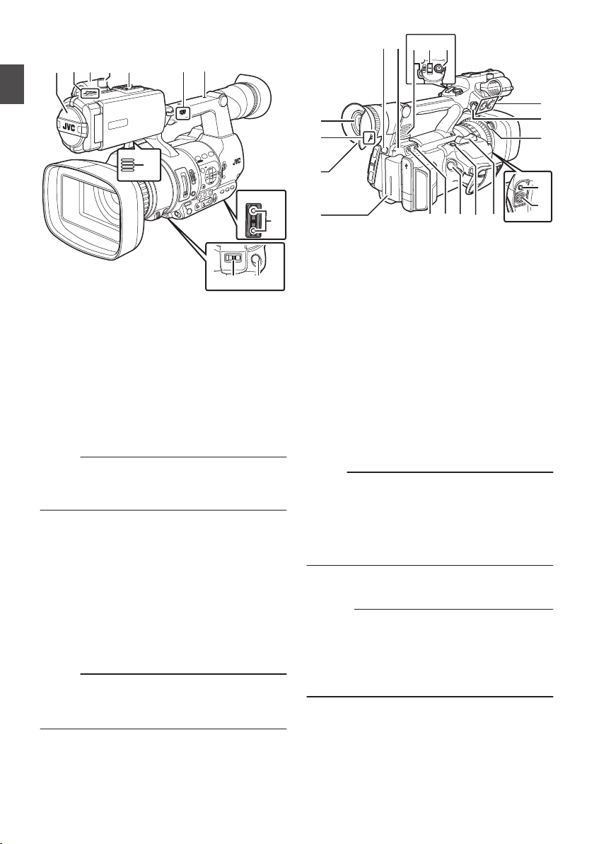
Side Control Panel
SCENE SELECT
FOCUS
LOCK
AE LEVEL
MANU
AUTO
MENU/THUMB
FOCUS ASSIST/1 OIS / 2 LOLUX / 3
B
A
OFF
PRESET
IRIS
GAIN
CANCEL
L
M
H
B
A
WHT BAL SHUTTER
FULL AUTO
MODE
POWER
ON
OFF
ON
OFF
AE LOCK/4 ZEBRA/5 MARKER/6
PUSH AUTO
TIME CODE
AUTO
A
B
C
E
S R Q
O
N
MLKJ
T
D
P
H
I
U
F G
A
B
C
D
DEVICE
AV
HDMI
REMOTE
DC
POWER
/CHG
BATT.RELEASE
A
B
OPEN
CLOSE
AV
DEVICE
DC
REMOTE
C
B
A
D
E
SD Slot
Introduction
.
A
[FOCUS AUTO / MANU / BAUTO] Focus
Switch
B
[SCENE SELECT
C
[LOCK] Auto Focus Lock Button
D
[IRIS] Iris Auto/Manual Selection Button
E
[PUSH AUTO] Iris Push Auto Button
F
[GAIN] Gain Auto/Manual Selection Button / [L/
] Scene Selection Switch
M/H] Sensitivity Selection Switch
G
[WHT BAL] White Balance Auto/Manual
Selection Button / [B/A/PRESET] Selection
Switch
H
[SHUTTER] Shutter Speed Auto/Manual
Selection Button
I
[y] One Push Auto White Balance Button
J
[FULL AUTO ON/OFF] Full Auto Switch
For switching the Full Auto mode to ON/OFF.
Full Auto mode adjusts the Iris, Gain, Shutter
and White Balance automatically.
K
[AE LOCK/4] AE Lock/User 4 Button
L
[ZEBRA/5] Zebra/User 5 Button
M
[MARKER/6] Marker/User 6 Button
N
[MODE] Camera/Media Mode Selection Button
O
[POWER ON/OFF] Lock Power ON/OFF Switch
P
Cross-Shaped Button (JKHI)/Set Button (R)
Q
[LOLUX/3] Low-light Shooting/User 3 Button
R
[OIS/2] Optical Image Stabilizer/User 2 Button
S
[FOCUS ASSIST/1] Focus Assist/User 1 Button
T
[MENU/THUMB] Menu/Thumbnail Button
U
[CANCEL] Cancel Button
.
A
SD Card Cover
B
[SLOT A/B] Card Slot Selection Button
C
Card Slot B Status Indicator
D
Card Slot A Status Indicator
Rear Terminal
.
A
[DEVICE] USB Mini Terminal
B
[AV] AV Output Terminal
C
[HDMI] HDMI Output Terminal
D
[REMOTE] Remote Terminal
E
[DC] DC Input Terminal
Names of Parts
7
Page 8
LCD Monitor
MENU/THUMB
CANCEL
CH1
INT
INPUT1
INPUT2
AUTO
MANUAL
CH2
INPUT2
MONITOR
DISPLAY STATUS
INPUT1
PEAKINGLCD BRIGHT
CH2CH1
LINE
MIC
MIC
+48V
CH1
BOTH
CH2
B
C
H I
A
D
FG
E
JKLNM
D
C
A
B
Introduction
.
A
LCD Monitor
B
[MENU/THUMB]
C
LCD Cross-Shaped Button (JKHI)/Set Button
(R)
D
[CANCEL] Cancel Button
E
[CH1/CH2] CH1/CH2 Recording Level
Adjustment Knob
F
[LCD BRIGHT +/-] LCD Display Brightness
Adjustment Button
G
[PEAKING +/-] LCD/VF Contour Adjustment
Button
H
[DISPLAY] Display Button
I
[STATUS] Status Screen Display Button
J
[MONITOR]/[+/-] Audio Monitor Selection
Switch/Volume Adjustment Button
K
[INPUT1/INPUT2] Audio Input Signal Selection
Switch
L
[CH2] CH2 Audio Input Signal Selection Switch
M
[CH1] CH1 Audio Input Signal Selection Switch
N
[CH1/CH2 AUTO/MANUAL] CH1/CH2 Audio
Recording Mode Switch
Menu/Thumbnail Button
Lens Section
.
A
Filter Built-In Screw
0
Installable filter types: φ46mmP0.75
Memo :
0
Remove the lens hood when installing the filter.
B
Lens Cover Open/Close Switch
C
Focus/Zoom Ring
D
Iris Dial
8
Names of Parts
Page 9
Adjusting the Grip Belt
AUX
INPUT2
INPUT1
DEVICE
AV
A
BATT.RELEASE
POWER
/CHG
B
HDMI
REMOTE
DC
REC
TIME CODE
the pad and adjust the position of the grip belt
Open
accordingly.
.
Caution :
0
If
the grip is loose, the camera recorder may fall
off resulting in injuries or malfunction.
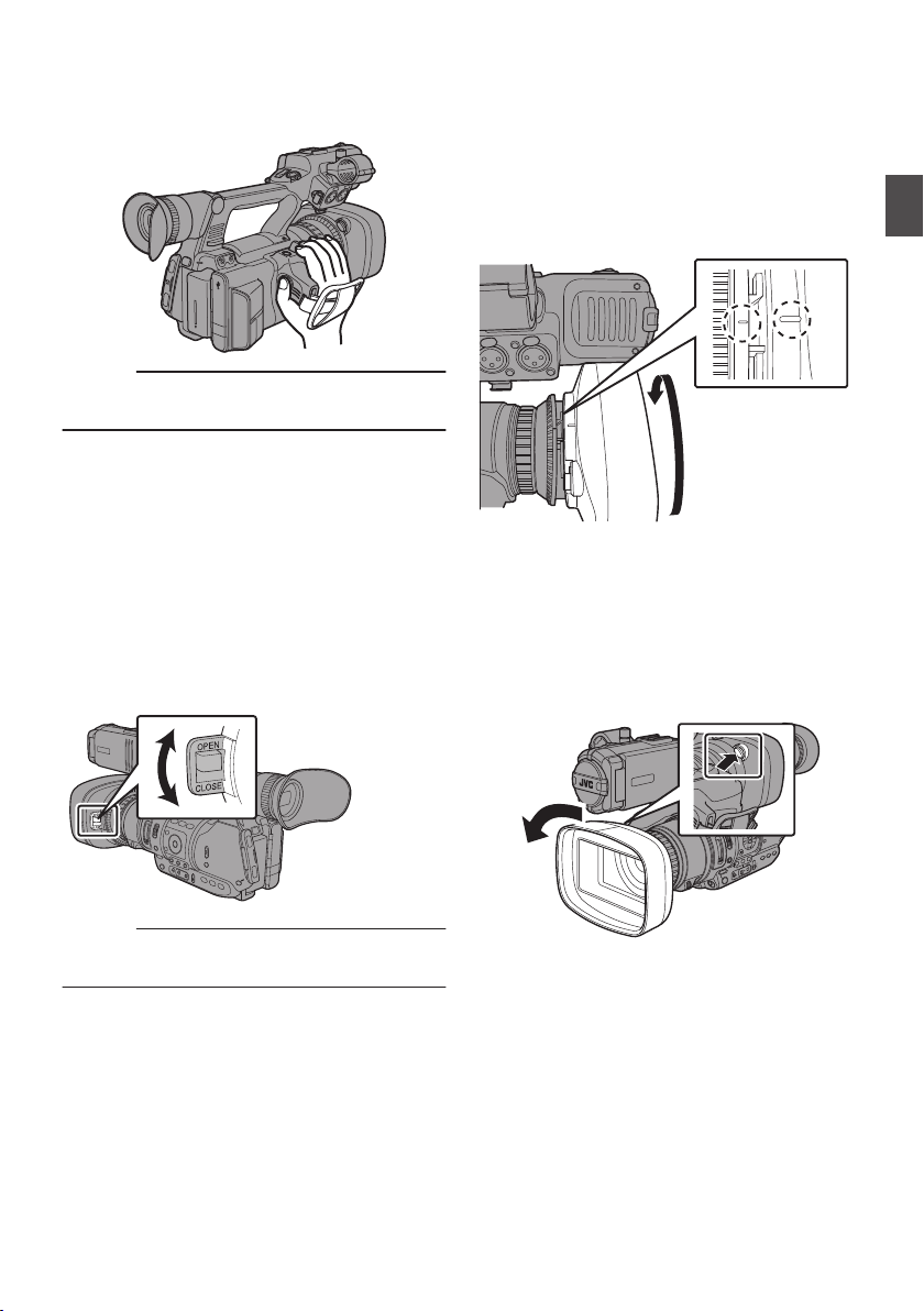
Attaching/Detaching the Hood
Attaching the Hood
Align the markings on the camera recorder and
turn the hood in the direction of the arrow until
hood;
it is locked.
Preparations
Opening/Closing the Lens Cover
Use the lens cover open/close switch to open or
close the lens cover.
Before shooting, open the lens cover.
this camera recorder is not in use, close the
When
lens cover to protect the lens.
.
Caution :
0
Do not press against the lens cover with force.
Doing so may damage the lens or the cover.
.
Detaching the Hood
0
Remove the hood when attaching a filter,
teleconverter
or wide converter to the front of the
lens.
0
While pressing the hood release button, turn the
hood in the direction of the arrow (anticlockwise) to remove it.
.
Adjusting the Grip Belt
9
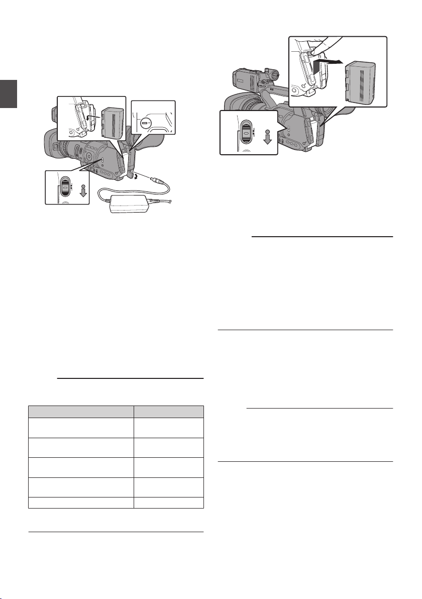
Page 10
Using a Battery Pack (sold
1
2
3
4
4
POWER
/CHG
MODE
POWER
ON
OFF
1
2
MODE
POWER
ON
OFF
separately)
Charging the Battery
Charge the battery immediately after purchase or
when the battery power is running low.
Preparations
.
1
Hold down the lock button (blue) at the
center of the [POWER ON/OFF] switch to set
to “OFF”.
2
Attach the battery.
Slide it in until you hear a click.
3
Connect the supplied AC adapter to the
terminal.
[DC]
Open the cover of the [DC]
as shown in the diagram.
4
Connect the AC adapter to a power outlet.
0
The [POWER/CHG] lamp blinks during
charging and will go out after charging is
complete.
0
Remove the AC adapter after charging is
complete.
Memo :
0
Blinking of the [POWER/CHG] lamp during
charging indicates the charge level.
[POWER/CHG] Lamp
Orange blinking
(4 times per second)
Orange blinking
(3 times per second)
Orange blinking
(2 times per second)
Orange blinking
(1 time per second)
Light goes out Fully charged
0
You
can charge the battery even when operating
the camera recorder using the AC adapter.
terminal and connect
Charge Level
Less than 25 %
Less than 50 %
Less than 75 %
Less than 100 %
Removing the Battery
.
1
Hold down the lock button (blue) at the
center of the [POWER ON/OFF] switch to set
to “OFF”.
2
While pressing and holding the [BATT.
RELEASE
] button, push up and remove the
battery in the direction of the arrow.
Caution :
0
Do not remove the battery when the [POWER
ON/OFF
0
Do not insert or remove the DC cable when the
] switch is “ON”.
battery is in use.
0
Leaving the camera recorder unused with the
battery inside will deplete the battery power
even if you set the
[POWER ON/OFF] switch to
“OFF”. Remove the battery if you are not using
the camera recorder.
Estimated Charging and Continuous
Operating Times
o
Charging time
Approx. 4 hrs (SSL-JVC50)
When the [POWER ON/OFF] switch is set to
*
“OFF”
Memo :
0
If
you charge the battery immediately after using
while the battery is still warm, it may not be fully
charged.
0
For details, refer to the “INSTRUCTIONS” of the
battery.
Using a Battery Pack (sold separately)
10
Page 11
o
TIME CODE
MODE
POWER
ON
OFF
AE LEVEL
MENU/THUMB
CANCEL
MENU/THUMB
CANCEL
Continuous operating time
Approx. 6 hrs (SSL-JVC50)
Memo :
0
operating times may differ depending on
Actual
the age of the battery, charging condition, and
operating environment.
0
Operating time is shortened in cold
environment.
0
The operating time may shorten when power
zoom is used, accessories are connected, or
when the LCD monitor is frequently used.
0
For purchase of spare batteries and battery
charger, please contact the local dealers in your
area.
Precautions for Batteries
0
Store the battery in a cool and dry place when
not in use. Do not expose the battery to high
temperatures (such as in a car under direct
sunlight). Failure to do so not only shortens the
battery life but also damages the battery.
0
If the operating time shortens drastically even
after charging, the battery may be reaching the
end of its life. Replace the battery with a new
one.
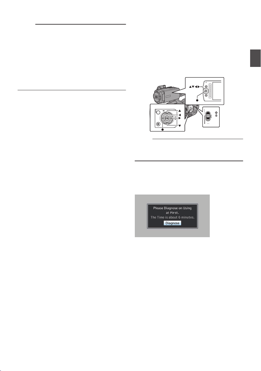
Configuring the Initial Settings
the power is first turned on, the Initial Setting
When
screen for performing the initial settings in the
camera recorder appears.
Set the date/time of the built-in clock in the [Initial
Setting] screen.
All operations are disabled until initial settings are
complete.
.
Memo :
0
is recommended to use the AC adapter as the
It
power supply.
0
Be sure to close the lens cover.
1
Hold down the lock button (blue) at the
center of the [POWER ON/OFF] switch to set
to “ON”.
The Initial Setting screen appears.
Preparations
.
Using a Battery Pack (sold separately)
11
Page 12
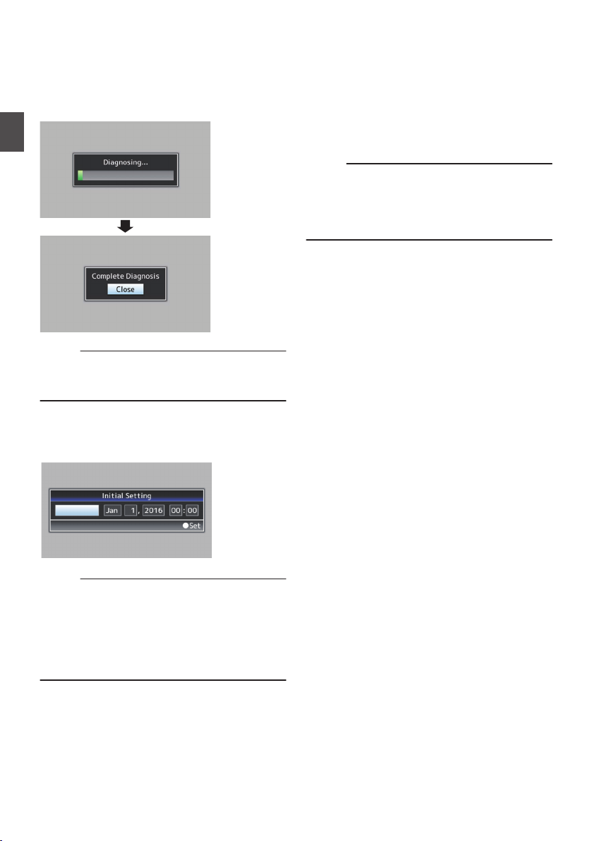
2
UTC+05:30
Ensure that the lens cover is closed, and
press the Set button (R).
0
Self-diagnosis starts.
0
A progress bar appears, and “Complete
Diagnosis
” appears when the diagnosis is
complete.
Preparations
.
Memo :
0
It takes about 6 minutes to complete the
diagnosis.
or turn off the camera recorder.
3
Press the Set button (R) after confirming
the exit screen.
The [Initial Setting] screen appears.
During the diagnosis, do not operate
4
Set the time zone and date/time.
A
Move the cursor with the cross-shaped button
(HI) and select the setting item.
B
Change the values with the cross-shaped
button (JK).
5
Press the Set button (R) after setting is
complete.
The clock is set to 0 seconds of the input date/
time.
Memo :
0
configured date/time data can be displayed
The
on the LCD monitor and viewfinder and be
recorded to the SD card.
0
The value of the year can be set in the range of
“2000” to “2099”.
.
Memo :
0
The
[Initial Setting] screen appears when the
power is turned on for the first time and when the
power is turned on after the built-in battery is fully
discharged.
0
The configured date/time data is saved in the
built-in
rechargeable battery even if the power is
turned off.
Configuring the Initial Settings
12
Page 13
Usable Cards
1
2
3
1
A
B
2
Use a Class 6/10 SD card.
Memo :
0
Depending on the recording format, SD card
with Class 4 or higher performance can also be
used.
0
To use an SDHC card, set
[4GB File
Spanning(SDXC)] to “On”.
Caution :
0
Using cards other than those from Panasonic,
TOSHIBA or SanDisk may result in recording
failure or data loss.
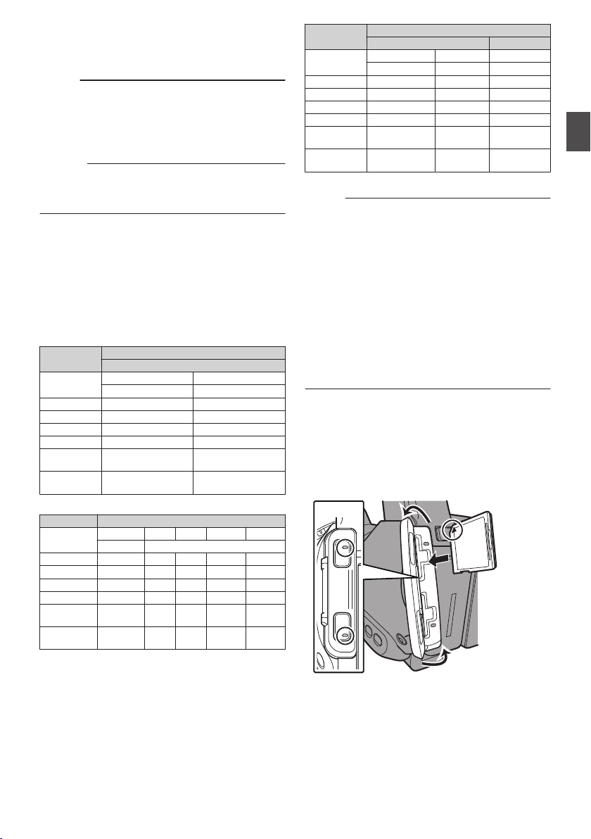
Estimated Recordable Time of SD Cards
The estimated recordable time is only a guide.
Differences may occur depending on the SD card
in use and the battery condition.
4 GB 17 12
8 GB 35 25
16 GB 70 50
32 GB 140 100
64 GB
(SDXC)
128 GB
(SDXC)
4 GB 16 19 25 46 82
8 GB 33 39 50 95 168
16 GB 67 78 100 190 336
32 GB 135 156 200 380 672
64 GB
(SDXC)
128 GB
(SDXC)
HQ HQ SP LP EP
1080p 1080i
270 312 400 760 1344
540 624 800 1520 2688
QuickTime/MP4
MPEG2/HD
SP HQ
1080i 720p/1080i
280 200
560 400
AVCHD
(Unit: minute)
(Unit: minute)
4 GB 9 12 47
8 GB 18 25 95
16 GB 36 50 190
32 GB 72 100 380
64 GB
(SDXC)
128 GB
(SDXC)
XHQ UHQ -
1080i/1080p 1080i 576i
145 200 760
290 400 1520
QuickTime
H.264/HD H.264/SD
(Unit: minute)
Memo :
0
If the SD card contains files recorded by devices
other than this camera recorder or files that are
saved from a PC, the recordable time may be
shorter or data may not be properly recorded.
0
The number of clips that can be recorded to one
SD card on this camera recorder for each file
format is restricted.
Up to 600 clips can be recorded for the
“QuickTime” file format and 4000 clips for the
“AVCHD” file format. When the maximum
number of clips is reached, the remaining space
is displayed as “0 min” regardless of the
estimated recordable time, and no further
recording can be made.
Inserting an SD Card
This camera recorder comes with two card slots
(Slot A and B) for video/audio recording and
playback.
.
1
Open the SD card cover.
2
Insert an SD card with the notched corner
pointing up.
The status indicator of the card slot to which the
card was inserted lights up in red.
3
Close the SD card cover.
Usable Cards
Preparations
13
Page 14

Formatting (Initializing) SD Cards
2
4
When the following cards are inserted, [!FORMAT]
appears at the remaining media display area.
Format the card using the camera recorder menu.
0
Unformatted SD cards
0
SD cards formatted under different
specifications
Caution :
0
Be sure to format the SD card on this camera
Preparations
recorder.
peripheral equipment cannot be used on this
camera recorder.
0
[!RESTORE] appears at the remaining media
display area when an SD card that requires
restoring is inserted.
1
Select [System] B [Media] B [Format
Media]
2
Select the slot of the SD card to be
formatted and press the Set button (R).
.
3
The status of the selected SD card appears.
4
Select [Format] and press the Set button
(R).
SD cards formatted on a PC and other
.
5
Formatting starts.
.
6
Formatting is complete.
When formatting is complete, “Complete” appears
and the camera recorder returns to the [Format
Media] screen.
Memo :
0
During formatting, menu operation is
unavailable but you can start recording.
However, this is only available when a
recordable SD card is inserted in the other slot.
0
Formatting
cases.
0
0
0
cannot be performed in the following
Recording is in progress on the SD card to be
formatted.
SD card is not inserted.
Write-protect switch of the SD card is set (z
is displayed).
Caution :
0
If you format the SD card, all data recorded on
the card, including video data and setup files,
will be deleted.
.
Inserting an SD Card
14
Page 15

Clips Recorded to SD Cards
ABCG0001
This is set to “xxxG” (“xxx” denotes the last 3
digits of the serial number) by default.
Clip Name Prefix (any four alphanumeric characters)
The Clip Number can be reset in
the menu.*
A number in automatic
ascending order is assigned in
the recording order.
Clip Number
Folders in the SD Card
Images recorded are sorted into the respective
folders according to the menu settings below.
Select which folder to record to from the menu.
*
System Format Record Folder
HD QuickTime
HD/SD
(MPEG2)
MP4(MPEG2) PRIVATE/JVC/BPAV
AVCHD PRIVATE/AVCHD
QuickTime(H.264)
Memo :
0
By formatting (initializing) the SD card from the
[Format Media] menu on the camera recorder,
folders required for recording in the current
[System] settings will be generated.
0
When the
[System] settings and
[QuickTime(MPEG2)] settings are changed,
folders required for recording in those settings
will be automatically generated.
Caution :
0
a clip inside the folder is moved or deleted
When
using the Explorer (Windows) or Finder (Mac),
recording to the SD card may fail if formatting
(initializing) of the card is not performed.
Clip (Recorded Data) and Clip Name
0
When recording is stopped, the images, audio
and accompanying data which are recorded
from start to stop are recorded as one “clip” on
the SD card.
0
An 8-character clip name is automatically
generated for the recorded clip.
(“Clip Name Prefix” + “Clip Number”)
0
When [Main Menu] B [System] B [Record
Set] B [Record Format
“AVCHD”, the clip name generated consists of
only the Clip Number (5-digit number).
DCIM or PRIVATE/JVC/
CQAV*
DCIM or PRIVATE/JVC/
CQAVC*
] B [Format] is set to
Example: In the case of QuickTime/MP4
.
* [Clip Set] B [Reset Clip Number]
Memo :
0
Before recording starts, you can set any
characters for the clip name prefix by using
Menu] B [System] B [Record Set] B [Clip
[Main
Set] B [Clip Name Prefix].
0
Changes cannot be made after recording.
Recorded Clips
0
recorded materials may be split into several
The
files but they can be played back continuously
on the camera recorder.
0
Clips may be recorded across the two SD cards
in card slots A and B depending on the recording
time of the clip.
Caution :
0
A clip recorded across several cards cannot be
back continuously. Continuous playback
played
is only possible when the recording is made on
one card.
Preparations
Inserting an SD Card
15
Page 16

Basic Shooting
3
1
MODE
POWER
ON
OFF
4
2
4
AE+6
12: 34 :56
Jan 12, 2016
00:00 :00.00
4030 20 10 0
P13000K
Procedures
Preparations
Shooting
.
1
Supply battery or AC adapter power to the
camera recorder.
2
Insert an SD card.
3
Turn on the power of the camera recorder.
Hold down the lock button (blue) at the center of
the [POWER ON/OFF] switch to set to “ON”. The
camera recorder starts up in Camera mode and
is ready for recording.
4
Adjust the angle of the LCD monitor and
viewfinder.
5
Configure [System], [Format], [Resolution]
Frame & Bit Rate] in [Main Menu] B
and [
[System] B [Record Set] B [Record
Format].
0
You can select the system definition (HD or
SD), file format for recording/playback and
the record format for video images on this
camera recorder.
0
Press the [MENU/THUMB] button on the
LCD monitor to display the menu screen on
the LCD monitor and viewfinder.
0
The following setting values are the factory
defaults.
[System]: HD
[Format]
: QuickTime(MPEG2)
[Resolution]: 1920x1080
[Frame & Bit Rate]: 50i(HQ)
Shooting
1
Configure the video and audio input
settings.
0
Set
the [FULL AUTO ON/OFF] switch to “ON”
to enter Full Auto mode. This mode adjusts
the Iris, Gain, Shutter and White Balance
automatically.
0
The
audio recording level is also set to Auto,
and audio from the built-in microphone is
recorded in the Full Auto mode.
0
The a icon appears at the lower center area
of the LCD in the Full Auto mode.
.
Memo :
0
To set each individual video setting item
automatically or manually, and to carry out the
audio input settings and the audio recording
level adjustment, select the item from the menu
and specify the setting individually.
2
Press the [REC
the SD card.
This camera recorder has three [REC]
Any of the [REC] buttons can be used to start/
stop recording by default.
The tally lamp lights up in red during recording.
0
Zoom Operation
0
Adjusting the Focus
Memo :
0
both the slots are loaded with recordable cards
If
in the factory default, pressing the [REC] button
starts recording only to the media in the selected
slot.
When [Main Menu] B [System] B [Record Set]
B [Slot Mode] is set to “Dual”, recording can be
performed simultaneously to the cards in both
the slots.
0
The tally lamp can be turned off in
[Tally Lamp].
3
Check the most recently captured images.
0
Press
activate the Clip Review function. The most
recently captured images are played back on
the LCD monitor and viewfinder screen.
0
After playback, the camera recorder returns
to standby mode (STBY).
] button to start recording to
buttons.
[System] B
the [C.REVIEW/7] button on the lens to
Basic Shooting Procedures
16
Page 17

Memo :
SCENE SELECT
B
A
OFF
1/100
F1. 6
0
dB
AE+6
12 :34 :56
Jan 12, 2016
00:00 :00.00
4030 20 10 0
5 . 6 f t
P13000K
Cursor
(Orange Frame)
Check Mark
0
[Clip Review
] is assigned to [C.REVIEW/7]
button in factory default.
0
[Clip
Review] can also be assigned to other user
buttons.
Using Scene Select
2
Press the [MENU/THUMB] button.
The Scene Select setting menu appears.
Changing Scene Select
Use the [SCENE SELECT] switch to change
camera settings easily and promptly according to
specific scenarios.
Set the [SCENE SELECT
] switch to “A” or “B” to
enter the Scene Select mode. This allows the
camera recorder to enter a preset shooting mode.
.
When the camera recorder is in the Scene Select
mode, “SCN
.
A” or “SCN B” appears on the screen.
Setting Scene Select
You can set different shooting modes for “A” and
“B” of the [SCENE SELECT
1
Set the [SCENE SELECT] switch to “A” or
.
“B”
The camera recorder switches to the desired
set position (“A”
or “B”).
] switch.
.
3
Select a shooting mode.
0
Use the cross-shaped button (JKH I) to
the orange cursor. Select icons for the
move
shooting mode and press the Set button (R).
0
being selected are indicated by a check
Icons
mark (P). Press the Set button again to
remove the check mark.
0
a check mark appears beside an icon,
When
select i (Adjust) and press the Set button to
display the Adjust screen. You can adjust the
selected shooting mode.
4
Press the [MENU/THUMB] button.
Returns to the normal screen.
Memo :
0
Scene Select mode operates regardless of
The
the [FULL AUTO ON/OFF] switch setting.
However, Full Auto mode will be “ON”.
0
The status of the selected shooting mode can
be saved in both
“A” and “B” of the [SCENE
SELECT] switch.
0
If a check mark does not appear for “Bright
“Dark”, “Hi Contrast”, “Vivid” or “Sharp”, the
Adjust screen will not appear.
0
When the Scene Select setting menu is
displayed, changing the [SCENE SELECT
switch to “OFF” will close the Scene Select
setting menu and return to the normal screen.
0
When
the [SCENE SELECT] switch is set to “A”
or “B”, items in [Main Menu] B [Camera
Function] cannot be set.
0
Settings for [AE Level
] are disabled during the
Scene Select mode.
0
Settings for [
Camera Process] are disabled
during the Scene Select mode.
Shooting
”,
]
Basic Shooting Procedures
17
Page 18

List of Shooting Modes (Icon)
Icon Description
Select for indoor shooting.
.
Indoor (*1)
Select for outdoor shooting.
.
Outdoor (*1)
Returns all current setting values
for the [SCENE SELECT] switch
(“A” or “B”) to default.
Select to add contrast and
differentiate brightness and
darkness.
Shooting
.
(Reset)
.
Hi Contrast
Select when the background is
.
Bright (*2)
bright and the subject appears
against the backlight. Adjust
dark
when the subject becomes darker
than necessary in Auto Iris mode.
Select when the background is
dark
.
Dark (*2)
and the subject is too bright.
Adjust when the subject becomes
brighter than necessary in Auto
Iris mode.
Select for shooting vivid and
.
colorful subjects.
Vivid
Select to emphasize the contour
.
of the subject.
Sharp
Displays the adjustment screen.
for each setting value can
.
(Adjust)
Details
be configured.
Displays the menu screen.
.
(Menu)
*1 “Indoor” and “Outdoor” cannot be selected at
the same time.
*2
“Bright” and “Dark” cannot be selected at the
same time.
Detailed Settings for Shooting Mode
.
1
Adjust the setting values.
A
Select the item to adjust.
Select the item to adjust using the crossshaped button (JK), and press the Set
button (R).
B
Select the setting value.
Change the setting value using the crossshaped button (JK), and press the Set
button (R).
The settable items and their values are as
follows.
Contrast
: -3 to +3 (Default value: +2)
Brightness : 0 to 6 (Default value: 3)
Darkness : 0 to 6 (Default value: 3)
Vividness : -5 to +5 (Default value: +3)
Sharpness : -3 to +3 (Default value: +2)
Memo :
0
default value is the one with the check mark
The
beside the icon in the Scene Select setting
menu.
0
For items without a check mark beside the icons
in the Scene Select setting menu, the setting
values are fixed at “0” and cannot be changed.
2
Press the crossed-shaped button (H) or
[CANCEL]
0
Returns to the Scene Select setting menu.
0
Press
button.
the [MENU/THUMB] button to return to
the normal screen.
Memo :
0
When the Adjust screen is displayed, changing
the [SCENE
SELECT] switch to “OFF” will close
the Adjust screen and return to the normal
screen.
Using Scene Select
18
Page 19

Miscellaneous Functions for Shooting and Recording Methods
This camera recorder is equipped with various
functions for shooting.
The functions described here are the typical
functions of the camera recorder.
Miscellaneous Functions for Shooting
0
Assignment of user buttons:
You
can assign functions to the buttons and use
them as user buttons.
Functions can be assigned to the buttons
according to the usability.
0
AF assist:
Allows you to set the auto focus point to the
preferred area or to near and far directions.
0
Focus Assist:
The focused area is displayed in color to allow
easy and accurate focusing.
0
Expanded focus:
Magnifies the preferred area to enable precise
focus to be established easily.
0
Zebra pattern:
Diagonal lines (zebra pattern) are displayed
only at the area with the specified luminance
levels.
0
Marker:
Displays the marker and safety zone when
determining the angle of view for the image
according to the shooting purpose.
Recording Methods
A
Recording using both slots A and B
0
Continuous recording (Series Rec):
Enables seamless long hour continuous
recordings over the slots.
0
0
B
Special recording
Special recording can be specified in
*
conjunction with A under given conditions.
0
0
0
0
C
Other recordings
0
simultaneously at the same definition
Record
(Dual Rec):
Allows you to create two clips of the same
content at the same time only on this camera
recorder.
Backup Rec:
Allows you to record only the preferred
scenes to one slot using the record and stop
operations while the other slot is continuously
recording.
Pre Rec:
Enables
duration in seconds of the video and audio
before the actual recording start time. This
allows you to record a complete event without
missing the initial scenes even if you start the
recording late.
Clip Continuous Rec:
Allows you to consolidate several rounds of
“startstop recording” into one clip. You can
consolidate the clips while recording when
shooting on-and-off and shooting several
scenes.
Frame Rec:
Records as a single clip only in the specified
frame rate until the recording is stopped.
Useful for shooting clay animation.
Interval Rec:
Records and pauses repeatedly at the
specified time interval and frame rate, and
records as a single clip until the recording is
stopped.
Useful for observation recording.
Clip cutter trig:
You can split the clips freely without having
to stop recording during shooting.
recording to go back to the specified
Shooting
Miscellaneous Functions for Shooting and Recording Methods
19
Page 20

Playing Recorded Clips
AE LEVEL
MENU/THUMB
CANCEL
A
C
B
the operation buttons on the side control panel
Use
of the camera recorder to play back.
.
Playback
A
IW Button
0
Plays back/pauses the clip pointed by the
cursor.
0
can press the cross-shaped button (HI)
You
to perform frame-by-frame forward playback
during pause mode.
B
S/T
C
o Button
1
2
Button
Skips in the reverse or forward direction.
O/N Button
During Playback:
Fast forwards in the reverse or forward
direction.
While paused:
Frame-by-frame playback in the reverse or
forward direction.
Stops playback.
In the thumbnail screen, move the cursor to
the clip to be played back.
Move the cursor to the clip to be played back
using the cross-shaped button (JKH I).
Press the playback/pause button.
Playback of the selected clip starts.
Time Code Playback
code or user’s bit recorded on an SD card can
Time
be displayed on the LCD monitor and viewfinder.
Memo :
0
The time code is also superimposed on the
signal output from the [HD/SD SDI] output
video
terminal.
0
If
a section without time code is played back, the
time code will stop. However, playback will
continue.
Audio Output during Playback
0
You can confirm the playback sound from the
monitor speaker, or the headphone connected
to the [x] terminal. When a headphone is
connected
to the [x] terminal, sound cannot be
output from the monitor speaker.
0
Adjust the volume of the monitor speaker and
headphone using the [MONITOR +/-] volume
adjustment button on the LCD monitor section
of the camera recorder.
Playing Recorded Clips
20
Page 21

Connecting External
AUX
INPUT2
INPUT1
DEVICE
AV
A
BATT.RELEASE
POWER
/CHG
B
HDMI
REMOTE
DC
REC
AV
DEVICE
DC
REMOTE
Audio (Lch)
Audio (Rch)
Video
GND
HDMI
AV input
Monitor
0
To output live or playback video images and
audio sound to an external monitor, select the
output signals from the camera recorder, and
using an appropriate cable according to
connect
the monitor to be used.
0
Choose the most suitable terminal according to
the monitor in use.
0
[AV] terminal:
Outputs composite video and audio signals.
0
[HDMI] terminal:
Outputs HDMI signals.
Configure the settings in the [A/V Set] menu to
match the monitor to be connected.
Memo :
0
If the [HDMI] terminal is connected, configure
the settings in the [A/V Set] menu according to
the monitor to be connected.
* Select the output signal in [A/V Set] B [HDMI
out].
display the menu screen or display screen on
* To
an external monitor, set [A/V Set] B [Video
Set]
B [Display On TV] to “On”.
Setting the Aspect
0
For setting the mode to convert images with a
16:9 aspect ratio to display on a 4:3 aspect ratio
screen.
0
Set using [A/V Set] B [Video Set] B [SD
Aspect].
0
The
available modes include “Side Cut”, “Letter”
(blackened at the top and bottom), and
“Squeeze” (full size, compressed at the left and
right).
Memo :
0
When [Record Format] B [System] is set to “SD”,
and [SD Aspect] is set to “4:3”, this item cannot be
selected.
Connecting External Devices
.
Connecting External Monitor
21
Page 22

Loading Clips to the PC
AUX
INPUT2
INPUT1
DEVICE
AV
A
BATT.RELEASE
POWER
/CHG
B
HDMI
REMOTE
DC
REC
AV
DEVICE
PC
2
0
You can load clips to a PC by connecting the
camera recorder to the PC via the USB port.
Doing so enables clips stored in the SD card to
be managed and edited on the PC.
0
on the SD card can be managed/edited on
Files
the connected PC in this mode only for USB
mass storage class devices that are recognized
by the said PC as a peripheral drive.
Memo :
0
Files cannot be written to the SD card.
1
Connect the camera recorder to the PC
using a USB cable.
A confirmation message “Change to USB
to enable the USB connection appears.
Mode?”
Connecting External Devices
.
2
Select [Change] using the cross-shaped
button (JK), and press the Set button (R).
The camera recorder switches to USB mode.
.
Memo :
0
If recording is in progress, the “Change to USB
Mode?” message appears after recording
stops.
0
If playback is in progress, the camera recorder
switches to USB mode after the file closes
automatically, such as when playback stops.
Disconnecting
0
the connection on the PC, then remove
Disable
the USB cable from the camera recorder.
0
Doing so exits the USB mode and switches the
camera recorder to Camera mode.
Memo :
0
procedure for disabling the USB connection
The
varies according to the PC in use. For details,
refer to the “INSTRUCTIONS” of the PC.
Loading Clips to the PC
22
Page 23

Menu Screen Hierarchical
Reset Process
Color Gain
Adjust...
Color Matrix
White Balance...
Gamma
White Clip
Black Toe
Master Black
Adjust...Detail
Camera Process...
Handle Zoom Speed
AE LEVEL SW
GAIN H
GAIN M
GAIN L
Smooth Trans
Dynamic Zoom
AGC Limit
AE Speed
AE Level
Shutter
Flicker Correction
OIS
Bars
Camera Function...
Main Menu...
AF Speed
User Switch Set...
AF Assist
System Information
Time Zone
Reserved
Date/Time
Reset All
Tally Lamp
Auto Power Off
Setup File...
Media...
Record Set...
System...
Audio Set...
Video Set...
A/V Set...
LCD Mirror
LCD Backlight
LCD Contrast
VF Contrast
VF Bright
LCD + VF
Display Settings...
Marker Settings...
Shooting Assist...
LCD/VF...
Drop Frame
UB Mode
TC Preset
TC Generator
TC/UB...
Chart
.
* Only menu items that can be set using this camera recorder are introduced here.
For details on each item, please refer to the “Mobile User Guide”.
.
Menu Screen Hierarchical Chart
Others
23
Page 24
Basic Operations in Menu
AE LEVEL
MENU/THUMB
CANCEL
FOCUS ASSIST/1 OIS / 2
TIME CODE
MENU/THUMB
CANCEL
DISPLAY
A
D
B
C
A
B
C
D
E F
G
Screen
0
Press the [MENU/THUMB] button on the side
control panel of the camera recorder or on the
LCD monitor to display the menu screen on the
LCD monitor and viewfinder.
0
Various settings for shooting and playback can
be configured on the menu screen.
0
There are two types of menu screens Menu] and [Favorites Menu].
0
[
Main Menu] contains all the setting items of the
camera recorder, classified according to
functions and uses, while [Favorites Menu]
allows users to customize the menu items freely.
0
The operating procedures and main screen
displays are the same for both menus.
0
The menu screen can also be displayed on
external
output terminal.
Operation Buttons
Use the operation buttons on the side control panel
Others
of the camera recorder or the buttons on the LCD
monitor to operate the menu.
monitors connected to the video signal
[Main
A
[MENU/THUMB]
0
Displays the menu screen. The
Button
[Main
Menu] screen is displayed by default.
0
During normal usage,
[Main Menu] is
displayed if the previous menu operation
ended at [Main Menu], and [Favorites
Menu] if the previous menu operation ended
at [Favorites Menu].
0
Press this button to close the menu screen
during
menu display and return to the normal
screen.
0
Pressing and holding down the button while
the menu is displayed switches the [Main
Menu] screen to the [Favorites Menu] or vice
versa.
B
[CANCEL
] Button
Cancels settings and returns to the previous
screen.
C
Set Button (R)
Sets the values and items.
D
Cross-shaped Button (JKH I)
J
: Moves the cursor upward.
K
: Moves the cursor downward.
H
: Moves back to the previous item.
I
: Moves forward to the next item.
E
[FOCUS ASSIST/1] Button
Adds the selected menu or submenu item to the
[Favorites Menu].
F
[OIS/2] Button
Resets settings in the [TC Preset] or [UB
Preset] setting screen. This button is disabled
in other screens.
G
[DISPLAY] Button
Switches between the [Main Menu] and
[Favorites Menu] screens.
.
Basic Operations in Menu Screen
24
Page 25

Display Screen
100min
50min
282min
0
P13000K
1/100
F1. 6
0
dB
AE+6
5 . 6 f t
100mi
n
50mi
n
282m
i
n
P 13000
1/1
00
6
0
d
B
AE
6
5.6
f
t
※2
※1
Y
G
X
A
cab
100min
50min
282min
0
P13000K
1/100
F1. 6
0
dB
AE+6
12 :34 : 56
Jan 12, 2016
00:00:00.00
4030 20 10 0
5 . 6 f t
G H I
100mi
n
50mi
n
82
※
A
F
K
J L
M
O
Q
R
S
U
T
VWb a
N
P
X
Yc
100min
50min
282min
0
P13000K
1/100
F1. 6
0
dB
AE+6
12 :34 : 56
Jan 12, 2016
00:00:00.00
1920x1080
50p HQ
4030 20 10 0
5 . 6 f t
P
c
C
F
KG
JH I L
M
O
Q
R
S
U
T
V
Z
X
D
E
B
N
Wb a
YA
Display Screen in Camera Mode
Display 0 screen
This screen displays the event. It is also used to
display warnings only.
.
*1 Appears only during warnings
*2
Appears only during operation
Display 1 screen
.
* Appears only during warnings
Display 2 screen
B
Voltage/Battery Power
Displays
the current status of the power supply
in use.
Memo :
0
Displayed
in the Display 0 and Display 1 screens
during warnings only.
C
Remaining Space on Media
Displays
the remaining recording time of the SD
cards in slot A and slot B separately.
W
: Currently selected slot. (White card)
W z : Write-protect switch of SD card is set.
W!INVALID : SD card cannot be read or
written to, or restored.
W!FORMAT : SD card requires
formatting.
W!RESTORE : SD card requires restoring.
W
!INCORRECT
0
When Record Set is set to other than
:
“AVCHD”/“SD” with a Class 4 SD card
inserted.
0
When the SD card is not supported.
0
When an SD card lower than Class 10 is
inserted while in the XHQ mode.
W!REC INH
0
When attempting to record in 50i(HQ)/
:
50i(SP) to an SD card recorded in
AVCHD60i(HQ)/60i(SP) (or vice versa).
0
When an SDHC card is inserted while
[4GB File Spanning(SDXC)] is set to “Off”.
Memo :
0
This item is not displayed when
[Main Menu] B
[LCD/VF] B [Display Settings] B [Media
Remain] is set to “Off”. However, warnings will
be displayed.
0
Displayed on the Display 0 and Display 1
screens
only in the case of warnings. (When the
remaining time is shorter than 3 minutes)
The icons appear on all display screens in the
following cases.
0
When recording is performed to only one
of the slots while [Main Menu] B [System]
B [Record Set] B [Slot Mode] is set to
“Dual”.
0
The displayed time is an estimate.
Others
.
A
OK Mark
Displayed
when OK mark has been appended.
Display Screen
25
Page 26

D
4030 20 10 0
4030 20 10 0
12
LCD BRIGHT
PEAKING
-10
0
0
Resolution
Displays the video image resolution.
Memo :
0
This item is not displayed when
[LCD/VF] B [Display Settings] B [Record
Format] is set to “Off”.
E
Frame Rate/Bit Rate
Displays the frame rate and bit rate in pairs.
Memo :
0
This item is not displayed when
[LCD/VF] B [Display Settings] B [Record
Format] is set to “Off”.
F
Audio Level Meter
0
Displays the audio levels of CH1 and CH2.
0
a appears on the screen when in the Auto
mode.
.
0
When [Main Menu
] B [System] B [Record
Set] B [Rec Mode] is set to “Frame Rec” or
Others
“Interval Rec”, audio cannot be recorded and
is indicated by the x mark.
.
Memo :
0
This item is not displayed when
[LCD/VF] B [Display Settings] B [Audio Meter]
is set to “Off”.
G
Volume Operation Indicator
Displayed
when there are changes made to the
volume of the headphone, speaker (0 to 15),
and the values of LCD BRIGHT, PEAKING (-10
to +10).
.
Memo :
0
There is no audio output from the speaker in
Camera mode.
[Main Menu] B
[Main Menu] B
[Main Menu] B
H
AE Lock
The U icon is displayed during AE lock.
I
Scene Select/Full Auto
0
When the [SCENE SELECT] switch is set to
“A” or “B”, this item appears as
“SCN A” or
“SCN B”.
0
If
the [SCENE SELECT] switch is set to “OFF”
and the [FULL AUTO ON/OFF] switch is set
to “ON”, the a icon appears.
J
Image Stabilizer Mark
Displayed when the image stabilizer is ON.
i
:
When [Level] of [OIS] is set to
“Normal”.
j
: When [Level] of [OIS] is set to
“High”.
Memo :
0
If image stabilizer is set to
“OFF” when the
Display 0 screen is displayed, h appears for 3
seconds.
0
Displayed in the Display 0 screen only when
there is a change.
K
White Balance Mode
Displays the current white balance mode.
(*****K indicates color temperature)
A<*****K> : When the white balance is set to
Auto A.
B<*****K> : When the white balance is set to
Auto B.
P<*****K> : When the white balance is set to
Preset.
<WBL> : Locked in the Full Auto White
Balance mode.
Memo :
0
Displayed in the Display 0 screen only when
there is a change.
L
Shutter
0
current shutter speed is displayed when
The
the shutter is set to “Manual”.
0
The shutter speed display disappears when
the [FULL AUTO ON/OFF
] switch is set to
“ON” to enable the Full Auto shooting mode,
or when the [SHUTTER] button is pressed to
enable the Automatic Shutter mode.
Memo :
0
The variable range of the shutter speed varies
according to the video format settings.
0
” is displayed when in the low-light
“OFF
shooting mode.
0
Displayed in the Display 0 screen only when
there is a change.
26
Display Screen
Page 27

M
Iris F-Number
Displays F-number of the lens iris.
N
Gain
0
Displays the gain value when in the Manual
Gain mode.
0
“LUX30”
shooting mode.
Memo :
0
Displayed in the Display 0 screen only when
there is a change.
O
AE Level
0
Displayed
0
When operated while manual operation is
disabled, “AE” blinks for about 5 seconds.
0
When face detection is enabled and
Detect] is set to “AF&AE”, q appears on the
left side of “AE”.
P
Beautiful Skin
e appears when Beautiful Skin is in
operation.
Memo :
0
If [Beautiful Skin] is turned off while the Display
0 screen is displayed, f appears for 3
seconds.
0
Displayed in the Display 0 screen only when
there is a change.
Q
Focus Display
0
Displays the approximate distance to the
subject in focus during manual focus.
0
When face detection is enabled, q appears
on the left side of e.
0
If
Assist] is set to “Area”, the
on the left side of e.
0
d appears on the screen while auto focus
is locked.
Memo :
0
You can specify the display method (Feet/
Meter) in [Main Menu] B [LCD/VF] B [
Settings] B [Focus].
This item will not be displayed when “Off” is
selected.
0
Displayed in the Display 0 screen only when
there is a change.
is displayed when in the low-light
when the AE function is activated.
[Main Menu] B [Camera Function] B [AF
icon appears
Display
[Face
R
Zebra pattern
During
zebra pattern display,
is displayed on the display screen in Camera
mode.
S
Focus Assist
0
“FOCUS
activated.
Memo :
0
Displayed in the Display 0 screen only when
there is a change.
T
Date/Time Display
Displays the current date and time.
Memo :
0
The date/time display style can be specified in
[Main
[Date Style]/[Time Style].
0
This item is not displayed when
[LCD/VF] B [Display Settings] B [Date/Time] is
set to “Off”.
0
When [Main Menu] B [System] B [Record Set]
B [Time Stamp
displayed.
U
Zoom Display
0
Displays the zoom position. (Zoom bar or
value)
.
.
0
The zoom bar will only be displayed for 3
seconds after the zoom operation is
activated.
0
The value will always be displayed.
Dynamic Zoom Off : Z00 to 99
Dynamic Zoom On
Dynamic Zoom Off : Z09 to 99
Dynamic Zoom On
” is displayed when auto focus is
Menu] B [LCD/VF] B [Display Settings] B
] is set to “On”, this item is not
Dynamic Zoom Off:
Dynamic Zoom On:
0
[Main Menu] B [Camera Function] B
If
[OIS] B [OIS] is set to “Off”, or [Level] is set
to “Normal”:
0
If [Main Menu] B [Camera Function] B
[OIS] B [Level] is set to “High”:
: Z00 to 149
: Z09 to 149
(zebra icon)
[Main Menu] B
Others
Display Screen
27
Page 28

Memo :
00:00:00:00
※
FF EE DD 20
0
You can specify the display method (Number/
Bar)
in [LCD/VF] B [Display Settings] B “Zoom”.
This item will not be displayed when “Off” is
selected.
0
Displayed in the Display 0 screen only when
there is a change.
V
Time Code (I)/User’s Bit (J) Display
0
Displays the time code (hour: minute:
frame) or user’s bit data recorded in
second:
the SD card being played back.
0
Example of time code display:
.
* Colon (:) denotes non-drop frames and dot (.)
denotes drop frames.
0
Example of user’s bit display:
.
Memo :
0
You can specify whether to display the time
Others
code, user’s bit, or turn off the display in
[LCD/VF] B [Display Settings
This item will not be displayed when “Off” is
selected.
W
Time Code Lock Indicator
When the built-in time code generator is
synchronized to the external time code data
input during the synchronization of time code
with another camera recorder, Z lights up.
X
Event/Warning Display Area
Displays error messages.
Y
Media Status
----
STBY : Recording standby
RREC : Recording
REVIEW : Clip Review
STBY P : Pre Rec recording standby
RRECP : Pre Rec recording
: No card found in the selected
slot
] B [TC/UB].
STBY C : Clip
RRECC : Clip Continuous Rec recording
STBYC
(displayed in
yellow)
STBY N : Interval Rec recording standby
STBYN
(displayed in
red)
RRECN : Interval Rec recording
STBY M : Frame Rec recording standby
RRECM : Frame Rec recording
STBYM
(displayed in
yellow)
STOP : Unable to record to the card in
P.OFF : Power OFF
Z
Dual Rec/Backup Rec Display
“DUAL” is displayed in the Dual Rec mode and
“BACKUP” is displayed in the Backup Rec
mode.
Memo :
0
This item is not displayed when
set to “Series”.
0
This item is not displayed when
[LCD/VF] B [Display Settings] B [Media
Remain] is set to “Off”. However, warnings will
be displayed.
0
Displayed
during warnings only. (When the remaining time
is shorter than 3 minutes)
a
Record Trigger
STBY B :
REC B : When [Rec Trigger] is set to “On”
b
Expanded focus
“EXPANDED” (yellow) is displayed during
expanded focus.
c
Operation lock
The r icon appears during operation lock.
in the Display 0 and Display 1 screens
When [Rec Trigger] is set to “On”
and recording is stopped
and recording is in progress
Continuous Rec recording
standby
: Clip Continuous Rec recording
pause
: Interval recording pause
: Frame Rec recording pause
the slot
[Slot Mode] is
[Main Menu] B
Display Screen
28
Page 29

Display Screen in Media Mode
282min
+5
1000/2000
A
G
LOMNK
282m
i
n
※
282min
0
12 :34 : 56
Jan 12, 2016
00:00:00.00
1920x1080
50p HQ
4030 20 10 0
1000/2000
A
F
G
I
JLOM
C
D
N
K
B
282min
0
12 :34 : 56
Jan 12, 2016
00:00:00.00
1920x1080
50 p HQ
4030 20 10 0
1000/2000
B
A
F
G
I
JLOM
C
D
N
E
K
H
4030 20 10 0
Media Display 0 Screen
This screen displays the media status or event. It
is also used to display warnings only.
.
* Appears only during warnings
Media Display 1 Screen
A
Media
0
Displays the media slot (A or B) of the
currently played clip.
0
z
appears when the write-protect switch of
the SD card is set.
B
Voltage/Battery Power
Displays
the current status of the power supply
in use.
Memo :
0
Displayed in the Media Display 0 screen during
warnings only.
C
Resolution
Displays the video image resolution.
D
Frame Rate/Bit Rate
Displays the frame rate and bit rate in pairs.
E
Operation Guide
Displays a guide for the current operation
buttons.
F
Audio Level Meter
Displays the audio levels of CH1 and CH2.
.
Media Display 2 Screen
.
.
Others
Memo :
0
This item is not displayed when [Main Menu] B
[LCD/VF] B [Display Settings] B [Audio Meter]
is set to “Off”.
G
Volume Operation Indicator
Displayed
when there are changes made to the
volume of the headphone, speaker (0 to 15),
and the value of LCD BRIGHT (-10 to +10).
H
Position bar
Displays the current position in the video.
During trimming, the position bar appears in
green, and icons for the in and out points are
displayed.
6
: Current position of the video
7
: Position to start trimming
(In point)
8
: Position to end trimming
(Out point)
I
Date/Time Display
Displays the date/time that is recorded on the
currently played SD card.
Memo :
0
The date/time display style can be specified in
[LCD/VF] B [Display Settings] B [Date Style]/
[Time Style].
Display Screen
29
Page 30

J
00:00:00:00
※
FF EE DD 20
Time Code (I)/User’s Bit (J) Display
0
Displays the time code (hour: minute:
second:
frame) or user’s bit data recorded in
the SD card being played back.
0
Example of time code display:
.
* Colon (:) denotes non-drop frames and dot (.)
denotes drop frames.
0
Example of user’s bit display:
.
Memo :
0
You can specify whether to display the time
code,
user’s bit, or turn off the display in [TC/UB]
of [Main Menu] B [LCD/VF] B [Display
Settings].
K
Event/Warning Display Area
Displays error messages.
L
Media Status
Others
PLAY
STILL : Still picture playback mode
FWD * : High-speed playback in the
REV * : High-speed playback in the
STOP : Stop mode
P.OFF : Power OFF
M
Check Mark
Displayed when the currently played clip is
selected.
N
OK Mark
Displayed when OK mark has been appended.
O
Clip Information
Displays current clip number/total number of
clips.
: Playing
forward direction (* playback
speed: 5x, 15x, 60x, or 360x)
reverse direction (* reverse
playback speed: 5x, 15x, 60x, or
360x)
Status Screen
0
This screen allows you to check the current
settings.
0
To display the status screen, press the
[STATUS
0
The status display differs according to the
operation mode (two types).
0
Press the [STATUS
display screen.
0
Press
screen (other than the [Camera 1]/[Camera 2]
screen) to enter the setting screen.
0
Use the cross-shaped button (HI) to switch
screens as follows:
] button in the normal screen.
] button to switch to the
the [MENU/THUMB] button at each status
Display Screen
30
.
* These are screen examples. The contents
displayed are different depending on the
settings.
Page 31

Troubleshooting
Symptom Action
Power does not turn on.
Unable to start recording.
Camera image is not output on
the LCD monitor and
viewfinder screen.
Playback does not start after
selecting a clip thumbnail and
pressing the Set button (R).
Images on the LCD monitor
and viewfinder screen appear
dark or blurred.
The [CH1/CH2]
adjustment knob does not
work.
SD card cannot be initialized
(formatted).
Battery alarm appears even
after loading a charged
battery.
The time code and user’s bit
are not displayed.
The date and time are not
displayed.
Incorrect display on the
viewfinder.
The actual recording time is
shorter than the estimated
time.
The two camera recorders are
not synchronized even though
the time codes have been
synchronized. (Z on the Slave
device is not displayed.)
recording level
0
Is the AC adapter properly connected?
0
Is the battery charged?
0
Is the power turned on immediately after it is turned off?
Make sure to wait for an interval of at least 5 seconds before turning
on the power again.
0
Is the record trigger button/lock switch on the handle turned on?
0
Is the write-protect switch of the SD card turned on?
Make sure that the write-protect switch is turned off.
0
Is the camera recorder set to the Camera mode?
Use the [MODE] selection button to switch to the Camera mode.
0
Is the SD card inserted compatible with the recording format?
0
Is the camera recorder set to the Camera mode?
Use the [MODE] selection button to switch to the Camera mode.
0
Is the selected clip a playable clip?
Playback
0
Readjust the brightness of the LCD monitor and viewfinder.
0
Is the iris closed?
0
Is the shutter speed setting too high?
0
Is the amount of peaking too little? Use the
adjust the contour for the LCD monitor and the viewfinder screen.
0
Is the [CH1/CH2 AUTO/MANUAL] switch set to “AUTO”?
0
Is the [FULL AUTO ON/OFF
Is the [FULL AUTO ON/OFF] switch set to “ON”, and [A/V Set] B
[Audio Set] B [Audio On FULL AUTO] set to “Auto”?
0
Is the write-protect switch of the SD card turned on?
Make sure that the write-protect switch is turned off.
0
Is the battery too old?
0
Even in Camera mode or Media mode, the time code and user’s bit
may not be displayed depending to the type of display.
0
Is [LCD/VF] B [
the time code or user’s bit, set it to “TC” or “UB”.
0
The date and time are only displayed on the Display 1 and Display 2
screens in the Camera mode (during shooting).
0
Is [System] B [Record Set
the date and time, set it to “Off”.
0
Is the LCD monitor used with [LCD/VF] B [LCD + VF] set to “Off”?
0
The recordable time may be shorter depending on the shooting
conditions or the subject.
0
Is the [
0
Set [System] B [Record Set] B [Record Format
Rate] such that the two camera recorders have the same frame rate.
is not possible if the clip has a different video format setting.
[PEAKING +/-] button to
] switch set to “ON”?
Display Settings] B [TC/UB] set to “Off”? To display
] B [Time Stamp] set to “On”? To display
TC IN/OUT] switch correctly set?
] B [Frame & Bit
Others
Troubleshooting
31
Page 32

Precautions for Proper Use
Power Saving
o
When this unit is not in use, be sure to set the
[POWER ON/OFF
reduce power consumption.
] switch to “OFF” in order to
Storage and Usage Locations
o
Allowable ambient temperature and humidity
Be sure to use this unit within the allowable
temperature
humidity of 30 % to 80 %. Using this unit at a
temperature or humidity outside the allowable
ranges could result not only in malfunction but
also serious impact on the CMOS elements as
small white spots may be generated. Please
exercise care during use.
o
Strong electromagnetic waves or magnetism
Noise may appear in the picture or audio and/or
the colors may be incorrect if this unit is used
near a radio or television transmitting antenna,
in places where strong magnetic fields are
generated by transformers, motors, etc., or near
devices emitting radio waves, such as
transceivers or cellular phones.
o
Use of wireless microphone near this unit
When a wireless microphone or wireless
Others
microphone tuner is used near this unit during
recording, the tuner could pick up noise.
o
Avoid using or placing this unit in the following
places.
0
Places subject to extreme heat or cold
0
Places with excessive dirt or dust
0
Places with high humidity or moisture
0
Places
a cooking stove
0
Places subject to strong vibrations or unstable
surfaces
0
In a parked car under direct sunlight or near a
heater for long hours
o
Do not place this unit at places that are subject
to
radiation or X-rays, or where corrosive gases
occur.
o
Protect
(Especially when shooting in the rain)
o
Protect
on a beach. In addition, salt and sand may
adhere to the body. Be sure to clean the unit after
use.
o
Protect this unit against penetration of dust
when using it in a place subject to sandy dust.
range of 0 °C to 40 °C and a relative
subject to smoke or vapor such as near
this unit from being splashed with water.
this unit from getting wet when shooting
Transportation
o
Do
not drop or hit this unit against a hard object
when transporting.
Maintenance
o
Turn off the power before performing any
maintenance.
o
Wipe the external cabinet of the unit with a soft
cloth. Do not wipe the body with benzene or
thinner.
Doing so may cause the surface to melt
or turn cloudy. When it is extremely dirty, soak
the cloth in a solution of neutral detergent, wipe
the body with it, and then use a clean cloth to
remove the detergent.
Rechargeable Battery (sold separately)
o
Be sure to use only the specified batteries.
We do not guarantee the safety and
performance of this device if an unspecified
battery is used.
o
details, refer to the “INSTRUCTIONS” of the
For
battery.
LCD Monitor and Viewfinder
o
The LCD monitor and viewfinder screen are
manufactured using high-precision technology.
spots may appear on the LCD monitor and
Black
viewfinder screen, or red, blue, and/or white
spots may not disappear. However, this is not a
malfunction and these spots are not recorded on
the SD card.
o
If you use this unit continuously for a long period
of time, the characters displayed in the
viewfinder may temporarily remain on the
screen. This is not recorded on the SD card.
They will not appear after you turn the power off
and then on again.
o
If you use this unit in a cold place, the images
may appear to lag on the screen, but this is not
a malfunction. Retained images are not
recorded on the SD card.
o
Do not press against the surface with force or
subject it to strong impact. Doing so may
damage or break the screens.
o
Noise may appear in the viewfinder when
switching between the live video and playback
images.
o
Due to the characteristic of the viewfinder
display device, colors may appear on the
images when you blink your eyes. It does not
affect the recorded images or HDMI output.
Precautions for Proper Use
32
Page 33

SDHC/SDXC Cards
Groove
o
SDHC/SDXC card is referred to as SD card in
this manual.
o
This camera recorder saves the recorded
images and audio sound on the SD card (sold
separately) in the card slot.
o
the SD card contains files recorded by devices
If
other than this camera recorder or files that are
saved from a PC, the recordable time may be
shorter or data may not be properly recorded. In
addition, the remaining space on the card may
not increase even when files are deleted using
a PC.
o
For details on the combinations of usable SD
card and format setting, refer to the following.
* Using cards other than those from Panasonic,
TOSHIBA or SanDisk may result in recording
failure or data loss.
Handling of SD Cards
o
The status indicator lights up in red when data
on the SD card is being accessed.
Do not remove the SD card during data access
as recording, playback, or formatting). Do
(such
not turn off the power or remove the battery and
AC adapter during access either.
o
Do not use or store the SD card in a place that
is subject to static electricity or electrical noise.
o
Do not place the SD card near locations that are
exposed to strong magnetic fields or radio
waves.
o
Inserting the SD card incorrectly may result in
damage of this unit or the SD card.
o
We are not liable for any accidental loss of data
stored on the SD card. Please back up any
important data.
o
Make use of the SD card within the prescribed
conditions of use.
Do not use it at the following locations.
Places that are subject to direct sunlight, high
humidity or corrosion, places near thermal
equipment, sandy or dusty places, or in a car
under the sun with the doors and windows
closed.
o
not bend or drop the SD card, or subject it to
Do
strong impact or vibration.
o
Do not splash the SD card with water.
o
Do not dismantle or modify the SD card.
o
Do not touch the terminals with your hands or
with a metal object.
o
Do not allow dust, dirt, water, or foreign objects
to adhere to the terminals.
o
Do not remove the labels or stick other labels or
stickers on the SD cards.
o
Do not use pencils or ballpoint pens to write on
the SD cards. Always use oil-based pens.
o
If you format (initialize) the SD card, all data
recorded on the card, including video data and
setup files, will be deleted.
o
You are recommended to use cards that are
formatted (initialized) on this camera recorder.
0
The SD card may be damaged if the camera
recorder is not operated correctly. Formatting
(Initializing) the SD card may allow it to
operate correctly.
0
SD cards that have been formatted
(initialized) on other cameras, computers or
peripheral equipment may not operate
correctly. In this case, format (initialize) the SD
card on this camera recorder.
o
If you want to wipe out all information by
completely erasing the data, we recommend
either using commercially available software
that is specially designed for that purpose, or by
physically destroying the SD card with a
hammer, etc. When formatting or erasing data
using the camera recorder, only the file
administration information is changed. The data
is not completely erased from the SD card.
o
Some commercially available SD cards may be
harder to be removed from this unit. Remove
them by hooking onto the groove on the cards.
0
It will be easier to remove the cards after
several times.
0
Do not stick any stickers on the cards.
o
The SD card may pop out when it is being
removed. Be careful not to lose the card.
.
Others
Precautions for Proper Use
33
Page 34

License Notices
o
MPEG LA AVC
THIS PRODUCT IS LICENSED UNDER THE
AVC PATENT PORTFOLIO LICENSE FOR
THE PERSONAL USE OF A CONSUMER OR
OTHER USES IN WHICH IT DOES NOT
RECEIVE REMUNERATION TO
(i) ENCODE VIDEO IN COMPLIANCE WITH
AVC STANDARD (“AVC VIDEO”) AND/OR
THE
(ii) DECODE AVC VIDEO THAT WAS
ENCODED BY A CONSUMER ENGAGED IN A
PERSONAL ACTIVITY AND/OR WAS
OBTAINED FROM A VIDEO PROVIDER
LICENSED TO PROVIDE AVC VIDEO.
NO LICENSE IS GRANTED OR SHALL BE
IMPLIED FOR ANY OTHER USE. ADDITIONAL
INFORMATION MAY BE OBTAINED FROM
MPEG LA, L.L.C. SEE
HTTP://WWW.MPEGLA.COM
o
MPEG LA MPEG-2 Patent
ANY USE OF THIS UNIT IN ANY MANNER
OTHER THAN PERSONAL USE THAT
COMPLIES WITH THE MPEG-2 STANDARD
FOR ENCODING VIDEO INFORMATION FOR
PACKAGED MEDIA IS EXPRESSLY
Others
PROHIBITED WITHOUT A LICENSE UNDER
APPLICABLE PATENTS IN THE MPEG-2
PATENT PORTFOLIO, WHICH LICENSE IS
AVAILABLE FROM MPEG LA, LLC, 6312 S.
LICENSE IS AVAILABLE FROM MPEG
WHICH
LA, LLC, 6312 S. Fiddlers Green circle, Suite
400E, Greenwood Village, Colorado 80111
U.S.A.
Copyright
o
Any recordings made on this camera recorder
that are played back for profit or public preview
may infringe on the rights of the owner of the
recordings.
Do not use the recordings for purpose other than
personal enjoyment without prior consent from
the owner.
Others
o
not insert objects other than the memory card
Do
into the card slot.
o
Do not block the vent on the unit.
Blocking of the vent causes internal heating and
may lead to burns and fires.
o
Do not put anything into the camera unit.
Metal and flammable items entering from the
vent and connectors can result in fire or electric
shock.
o
Do not turn off the [POWER ON/OFF] switch or
remove the power cable during recording or
playback.
o
The camera recorder may not show stable
pictures
power is turned on, but this is not a malfunction.
o
When the video signal output terminals are not
in use, put on the covers to prevent damage to
the terminals.
o
Do not drop this unit or subject it to strong impact
or vibration as it is a precision equipment.
o
Optical performance of lens
Due to the optical performance of the lens, color
divergence phenomena (magnification
chromatic aberration) may occur at the
periphery of the image. This is not a camera
malfunction.
o
Noise may appear in the image when switching
modes.
o
If placed on its side, heat release efficiency will
deteriorate.
o
Use the supplied AC adapter as the power
supply. Do not use the supplied AC adapter on
other devices.
o
When
covers are not in use, put on the covers to
prevent damage to the connectors.
o
This camera recorder makes use of fonts by
Fontworks Inc.
o
This camera recorder makes use of M+FONTS.
for a few seconds immediately after the
the connectors that come with connector
Precautions for Proper Use
34
Page 35

Content of this manual
0
All rights reserved by JVC KENWOOD
Corporation. Unauthorized duplication or
reprinting
strictly prohibited.
0
Illustrated designs, specifications and other
contents
for improvement without prior notice.
0
AVCHD Progressive and the AVCHD
Progressive logo are trademarks of
Panasonic Corporation and Sony
Corporation.
0
XDCAM EX is a trademark of Sony
Corporation.
0
SDXC and SDHC logos are trademarks of
SD-3C, LLC.
0
HDMI (High-Definition Multimedia Interface)
and 1 are trademarks of HDMI
Licensing, LLC.
0
QuickTime, Final Cut Pro, iPhone, iPad, iPod
touch, iOS, Mac OS and Safari are
trademarks of Apple Inc., registered in the
U.S. and other countries.
0
Android, Google Chrome and Nexus are
trademarks and/or registered trademarks of
Google Inc.
0
QR Code is a registered trademark of Denso
Wave Incorporated.
0
Dolby and the double-D symbol are
trademarks of Dolby Laboratories.
0
Microsoft, Windows, Windows Vista, and
Internet Explorer are either registered
trademarks or trademarks of Microsoft
Corporation in the United States and/or other
countries.
0
The company name of Fontworks, Fontworks,
and the name of the fonts are registered
trademarks of Fontworks Inc.
0
Other product and company names included
in this instruction manual are trademarks and/
or registered trademarks of their respective
companies. Marks such as ™ and ® have
been omitted in this manual.
of this manual, in whole or in part, is
of this manual are subject to change
Others
Precautions for Proper Use
35
Page 36

Specifications
General
Item Description
Power DC 12 V
Power
consumption
Mass Approx. 1.7 kg
Allowable
operating
temperature
Allowable
operating
humidity
Allowable
storage
temperature
Dimensions (W
× H × D)
Others
Terminal Section
Item Description
[HDMI] output
terminal (Type A)
[INPUT1/INPUT2] terminal
[MIC] -50 dBu, 3 kK, XLR (balanced),
[LINE] +4 dBu, 10 kK, XLR (balanced)
[AUX] terminal -22 dBu, 10 kK, 3.5 mm stereo
[AV] terminal Φ3.5 mm 4-pin mini jack
Video signal 1.0 V (p-p)
Audio signal -8 dBu (during reference level
[x] terminal Φ3.5 mm mini jack (stereo)
[REMOTE]
terminal
[U] terminal
[DEVICE] Mini USB-B type, USB 2.0,
[TC] terminal
[IN] 1.0 V (p-p) to 4.0 V (p-p) high
[OUT] 2.0 ± 1.0 V (p-p) low impedance
[DC] terminal DC jack (for the supplied AC
Approx. 6 W
(When recording in the factory
default settings using the
viewfinder.)
(When battery is not installed)
0 °C to 40 °C
30 %RH to 80 %RH
-20 °C to 50 °C
177.5 mm × 197 mm × 416 mm
V1.4-compliant
+48 V output (phantom power
supply)
mini jack (unbalanced)
input), 1 kK (unbalanced)
Φ2.5 mm mini jack (stereo)
slave function (mass storage
class) only
impedance
adapter)
Lens Section
Item Description
Lens F1.2, f=3.76 mm to 37.6 mm
Filter diameter Φ46 mm
(Conversion to 35 mm camera
format: f = 29.9 mm to 586 mm:
dynamic zoom)
Camera Section
Item Description
Image pickup
device
Gain 0dB, 3dB, 6dB, 9dB, 12dB,
Electronic
shutter
LCD monitor 3.5-inch LCD, 16:9, 920K pixels
Viewfinder 0.24-inch LCOS, 16:9, 1.56M
1/2.3-inch Progressive CMOS
18dB, 21dB, 24dB, Lolux,
15dB,
AGC
1/6.25 to 1/10000, EEI
pixels
Storage Section
Item Description
Supported
media
Slots x 2
SDHC/SDXC
36
Specifications
Page 37

Video/Audio
Item Description
Recording time Approx. 25 minutes (8 GB SD
HD mode (MOV/MP4: MPEG-2)
Video
recording file
format
Video
HQ mode MPEG-2 Long GOP VBR, 35
SP mode MPEG-2 Long GOP CBR 25
Audio LPCM 2ch, 48 kHz/16 Bit
HD mode (AVCHD)
Recording file
format
Video MPEG-4 AVC/H.264
Audio Dolby Digital 2ch, 48 kHz/16 Bit,
HQ Mode
(Progressive)
HQ mode 1920x1080/59.94i, 50i
SP mode 1920x1080/59.94i, 50i
LP mode 1440x1080/59.94i, 50i
EP mode 1440x1080/59.94i, 50i
HD mode (MOV: H.264)
Video
recording file
format
Video
XHQ Mode
UHQ Mode
Audio LPCM 2ch, 48 kHz/16 Bit
card, 35 Mbps, VBR mode)
QuickTime File Format (For
Final Cut Pro)/MP4 File Format
Mbps (Max) MP@HL,
1920x1080/59.94i, 50i
1440x1080/59.94i, 50i
1280x720/59.94p, 50p
Mbps MP@H14
1440x1080/59.94i, 50i
AVCHD File Format
256 kbps
1920x1080/59.94p, 50p
28 Mbps (Max)
24 Mbps (Max)
18 Mbps (Max)
9 Mbps
5 Mbps
QuickTime File Format
MPEG-4 AVC/H.264, 50 Mbps (Max)
1920×1080/59.94p, 59.94i, 50p, 50i
MPEG-4 AVC/H.264, 35 Mbps (Max)
1920x1080/59.94i, 50i
Item Description
SD mode (MOV: H.264)
Video
recording file
format
Video MPEG-4 AVC/H.264, 8 Mbps
Audio LPCM 2ch, 48 kHz/16 Bit
* The specifications and appearance of this
product are subject to changes for further
improvement without prior notice.
QuickTime File Format
720x576/50i
Others
Specifications
37
Page 38

Software License Agreement
software embedded in the Product (hereinafter
The
the “Licensed Software”) provided by
JVC KENWOOD Corporation (hereinafter the
“Licensor”) is copyrighted to or sublicensable by
the Licensor, and this Agreement provides for the
terms and conditions which Users shall follow in
order to use the Licensed Software. The User shall
use the Licensed Software by agreeing with the
terms of this Software License Agreement. This
Agreement shall be deemed completed at the time
the User (hereinafter the “User”) initially used the
Product in which the “Licensed Software” is
embedded.
The Licensed Software may include the software
which has been licensed to the Licensor directly or
indirectly from any third party. In such case, some
third parties require the Users to follow their
conditions for use separately from this Software
License Agreement. Such software shall not be
subject to this Agreement, and the Users are urged
to read the “Important Notice concerning the
Others
Software” to be provided separately.
Article 1 General Provision
The Licensor shall grant to the User a nonexclusive and non-transferable (other than the
exceptional
1) licensed to use the Licensed Software within the
country of the User (the country where the User
bought the Product (hereinafter the “Country”)).
Article 2 License
1. The license granted under this Agreement shall
be the right to use the Licensed Software in the
Product.
The User shall not duplicate, copy, modify, add,
2.
translate or otherwise alter, or lease the Licensed
Software and any related documents, whether in
whole or in part.
3. The use of the Licensed Software shall be limited
to personal purpose, and the Licensed Software
shall not be distributed, licensed or sub-licensed
whether it is for commercial purpose or not.
4. The User shall use the Licensed Software
according to the directions described in the
operation manual or help file, and is prohibited to
use or duplicate any data in a manner violating the
Copyright Law or any other laws and regulations by
applying whole or a part of the Licensed Software.
Article 3 Conditions for Grant of License
1. When the User transfers the Product, it may also
transfer the license to use the Licensed Software
embedded in the Product (including any related
materials,
no original, copies or related materials continue in
case referred to in Article 3, Paragraph
updates and upgrades) on condition that
the possession of the User, and that the User shall
cause the transferee to comply with this Software
License Agreement.
2.
The User shall not carry out reverse engineering,
disassembling, decompiling or any other code
analysis works in connection with the Licensed
Software.
Article 4 Right pertaining to the Licensed
Software
1. Any and all copyrights and other rights pertaining
to the Licensed Software and related documents
shall belong to the Licensor or the original holder
the right who granted to the Licensor the license
of
or sublicense for the Licensed Software
(hereinafter the “Original Rightholder”), and the
User shall not be entitled to any right other than the
license granted hereunder, in respect of the
Licensed Software and any related documents.
2. The User shall, whenever the User uses the
Licensed Software, comply with any laws relating
to the copyright and other intellectual property
rights.
Article 5 Indemnification of Licensor
1. Neither the Licensor nor the Original Rightholder
be liable for any damage incurred by the User
shall
or any third party due to the exercise of the license
granted to the User under this Agreement, unless
otherwise restricted by law.
2. The Licensor will offer no guarantee for the
merchantability, convertibility and consistency with
certain objective of the Licensed Software.
Article 6 Liability to Third Party
If any dispute has arisen with any third party due to
an infringement upon a copyright, patent or any
intellectual property right that was caused by
other
the User’s use of the Licensed Software, the User
shall settle such dispute at the User’s own cost and
hold the Licensor and the Original Rightholder
harmless from any inconvenience it may cause.
Article 7 Confidentiality
The User shall keep the confidentiality of such
portion of the Licensed Software, related
documents thereof or any other information to be
granted under this Agreement, as well as the
conditions
the public domain, and shall not disclose or divulge
the same to any third party without approval of the
Licensor.
Article 8 Termination
In case the User falls under any of the events
described in the following items, the Licensor may
immediately
the User compensates for the damage incurred by
the Licensor due to such event:
of this Agreement as has not yet entered
terminate this Agreement or claim that
Software License Agreement
38
Page 39

(1) when the User violated any provision of this
Agreement; or
when a petition has been filed against the User
(2)
for an attachment, provisional attachment,
provisional disposition or any other compulsory
execution.
Article 9 Destruction of the Licensed Software
If this Agreement is terminated pursuant to the
provision of Article 8, the User shall destroy the
Licensed Software, any related documents and
thereof within two (2) weeks from such date
copies
of termination.
Article 10 Export Restriction
1. The User shall understand that the Licensed
Software shall be subject to the export restrictions
adopted by the country of User and any other
countries.
2. The User shall agree that the software will be
subject to any and all applicable international and
domestic laws including the export control
regulation of the country of User and any other
countries,
users, the use by end-users and importing
countries to be provided by the country of User and
any other countries, and any other governmental
authorities.
Article 11 Miscellaneous
1. In the event any part of this Agreement is
invalidated by operation of law, the residual
provisions shall continue in force.
2. Matters not stipulated in this Agreement or any
ambiguity or question raised in the construction of
this Agreement shall be provided or settled upon
good-faith consultation between the Licensor and
the User.
3.
Agreement is governed by the laws of Japan, and
any dispute arising from, and relating to the rights
and obligations under, this Agreement shall be
submitted to the exclusive jurisdiction of the Tokyo
District Court for its first instance.
and any restrictions concerning the end-
The Licensor and the User hereby agree that this
Important Notice concerning the Software
Software License Attached to the Product :
The Software embedded in the Product is
composed of several independent software
components, and in each of such individual
components
a copyright of either JVC KENWOOD Corporation
(hereinafter “JKC”) or a third party subsists.
The Product uses the software component
designated in the End-User License Agreement
(hereinafter the “Licensed Software”),
that was executed between JKC and a third party
(hereinafter “EULA”).
The Licensed Software covers those
corresponding
of distribution of the software component in
executable format which is based on the license
granted under the GNU General Public License or
Lesser General Public License (hereinafter “GPL/
LGPL”), it requires an availability of the source
code for the relevant component. Please refer to
the following URL concerning the distribution of the
source code;
http://www3.jvckenwood.com/english/
download/gpl/index.html
Please note that we are unable to answer any
inquiry relating to the contents, etc. of the source
code. In addition, the Licensed Software includes
the software developed or created independently
by JKC and there exists an ownership of JKC in
such software and any accompanying documents,
which is protected by the Copyright Law, any
international treaties and other applicable laws. As
to matters concerning the handling by JKC of the
software components, please refer to the
“Software License Agreement” attached hereto.
Please note that any software component licensed
under “EULA” which is not subject to “GPL/LGPL”,
and those developed or created independently by
JKC shall not be subject to the requirement for
provision of the source code. The software
component distributed under “GPL/LGPL” shall be
licensed to users without charge, and, therefore, no
warranty is given for such software component,
either express or implied, within the scope of the
applicable laws and regulations. Unless otherwise
permitted by applicable laws and regulations or
agreed in written form, none of the owners of the
copyright or persons entitled to alter or redistribute
the software component under the said license
shall have any liability for any type of damage or
loss resulting from the use of or inability to use such
software component. For further details of the
conditions of use of such software component or
matters required to be complied with, please refer
to the relevant “GPL/LGPL”.
Users are urged to read the details for the relevant
license carefully before using the software
component covered by “GPL/LGPL” and
embedded in the Product. Since the terms and
conditions of individual licenses are provided by
parties other than JKC, the original English version
will be displayed by the Product.
A
Turn on the power.
B
Press the [MENU/THUMB] button.
C
Select [Main Menu
Information] B [Open Source License].
to free software, and, as a condition
] B [System] B [System
Others
Software License Agreement
39
Page 40

JY-HM360AG
HD MEMORY CARD CAMERA RECORDER
.
© 2016 JVC KENWOOD Corporation
B5A-1538-00
 Loading...