

Page 1

For Customer Use:
Smarthome.com, Inc. (800) SMART-HOME (949) 221-9200 http://smarthome.com
Enter below the Serial No. which is
located on the rear or bottom of
cabinet. Retain this information for
future reference.
Model No.
J X-S700
Page 2

WARNING: TO REDUCE THE RISK OF
Smarthome.com, Inc. (800) SMART-HOME (949) 221-9200 http://smarthome.com
FIRE OR ELECTRIC SHOCK, DO NOT
EXPOSE THIS APPLIANCE TO RAIN OR
MOISTURE.
CAUTION:
I
REFER
A
I
l
n
TO REDUCE THE RISK OF ELECTRIC SHOCK.
DO NOT REMOVE COVER (OR BACK).
NO USER-SERVICEABLE PARTS INSIDE.
SERWING
The lightning flash with arrowhead symbol, within
an equilateral triangle, is intended to alert the
user to the presence of uninsulated “dangerous
voltage” within the product’s enclosure that may
be of sufficient magnitude to constitute a risk of
electric shock to persons.
The exclamation point within an equilateral
triangle is intended to alert the user to the
presence of important operating and maintenance (servicing) instructions in the literature
accompanying the appliance.
TO QUALIFIED SERVICE PERSONNEL.
CAUTION: TO PREVENT ELECTRIC SHOCK DO
THIS (POLARIZED) PLUG WITH AN EXTENSION CORD,
RECEPTACLE OR OTHER OUTLET UNLESS THE BLADES
CAN BE FULLY INSERTED TO PREVENT BLADE EXPOSURE.
INFORMATION
This equipment has been tested and found to comply with the
limits for a Class B digital device, pursuant to Part 15 of the
FCC Rules. These limits are designed to provide reasonable
protection against harmful interference in a residential
installation. This equipment generates, uses, and can radiate
radio frequency energy and, if not installed and used in
accordance with the instructions, may cause harmful
I
interference to radio communications. However, there is
no guarantee that interference will not occur in a particular
installation. If this equipment does cause harmful interference
to radio or television reception, which can be determined by
turning the equipment off and on, the user is encouraged to try
to correct the interference by one or more of the following
measures:
-
Reorient or relocate the receiving antenna.
-
Increase the separation between the equipment and
receiver.
-
Connect the equipment into an outlet on a circuit different
from that to which the receiver is connected.
-
Consult the dealer or an experienced radio/TV technician for
help.
IMPORTANT
NOT
USE
--__
Thank you for purchasing this JVC product. CAUTION
Before you begin operating this unit, please read the
instructions carefully to ensure you obtain the best possible
performance.
If you have any questions, consult your JVC dealer.
IMPORTANT
rCONTENTS
FEATURES
System Connection Example
. . . . . . . . . . . . . . . . . . . . . . . . . . . . . . . . . . . . . . . . . . . . . . . . . . . . . . . . . .
. . . . . . . . . . . . . . . . . . . . . . . . . . . . . . . . . . . . . . . . . . . . . . . . . . . . . . . . . . . . .
. . . . . . . . . . . . . . . . . . . . . . . . . .
DESCRIPTION AND FUNCTIONS
Front Panel
Rear Panel
Remote Control
. . . . . . . . . . . . . . . . . . . . . . . . . . . . . . . . . . . . . . . . . . . . . . . . . . . . . .
. . . . . . . . . . . . . . . . . . . . . . . . . . . . . . . . . . . . . . . . . . . . . . . . . . . . . . .
. . . . . . . . . . . . . . . . . .
..-..........................
CONNECTIONS
Connection To TVs
Connection To VCRs
. . . . . . . . . . . . . . . . . . . . . .
. . . . . . . . . . . . . . . . . . . . . . . . . . . . . . . . . . . . . . . .
-
3
3
3
4
6
7
..-....................
8
10
To reduce the risk of electrical shocks, fire, etc.:
1.
Do not remove any screws, covers or the cabinet.
2. Do not expose this appliance to rain or moisture.
‘It may be unlawful to record or play back copyrighted
material without the consent of the copyright owner.
APPLICABLE OPERATIONS
How To Edit With
How To Edit With Audio Insertion .................
How To
Tips For Better Use ........................................ 22
BLOCK DIAGRAM
TROUBLESHOOTING
OPTIONAL CONNECTION CABLES
SPECIFICATIONS
BASIC OPERATION
How To
How To
WatchaVideo
Perform Video
Program . . . . . . . . . . . . . . . . . . . 12
Editing . . . . . . . . . . . . . . . . . . . . . . 14
__~
an
AV Processor.. ............. 16
Perform Parallel Editing.. .................
................................................ 24
........................................ 25
...............
................................................
.
18
.20
26
27
Page 3
1. Installation
Smarthome.com, Inc. (800) SMART-HOME (949) 221-9200 http://smarthome.com
l Select a place which is level, dry and neither too
hot nor too cold (between -5°C and 4O”C/23”F
and
104°F).
l Keep away from direct sunlight.
l Do not put it too close to a heater.
2. Power cord
l Do not handle the power cord with wet
l Do not bend the power cord sharply.
a
When unplugging from the wall outlet, always pull
hands1
the plug, not the power cord.
FEATURES
3. Malfunctions, etc.
l There are no user serviceable parts inside.
If problems occur, unplug the power cord and
consult your dealer.
l Do not insert any metallic objects.
l Do not allow water to get inside.
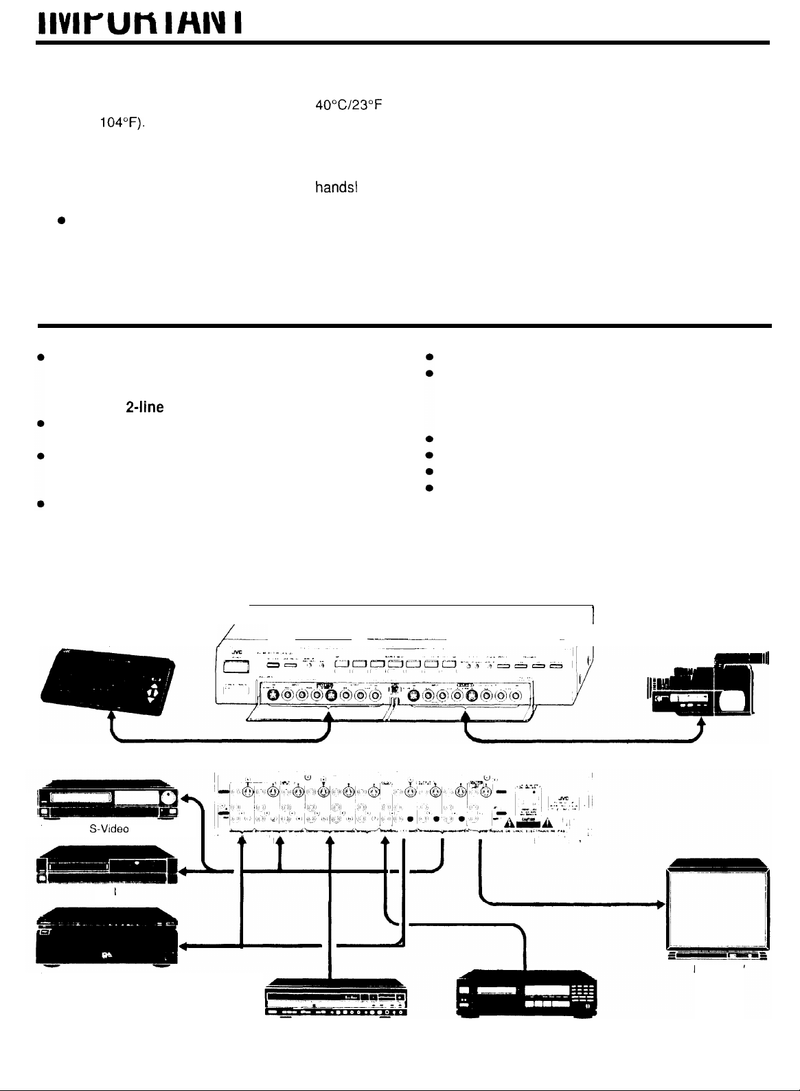
7 inputs, 4 outputs and 1 monitor output
Plus, audio AUX input and processor in/out
terminals enabling 4-line fully mutual editing,
as well as 2-line parallel editing.
Full compatibility with Super VHS VCRs
All sets of terminals include S-Video jacks.
Built-in Y/C Separator & Y/C Mixer circuit
Convenient when editing between VCRs with SVideo terminals and VCRs without S-Video terminals.
Built-in video amplifier
Capable of pro-quality 12 MHz video frequency
bandwidth and 960-line horizontal resolution.
System Connection Example
AV processor
/_
----
.
_____-__
Full function remote control provided
Dual operation with key lock function
In dual operation mode, 2 different input signals can
be routed independently. In addition, key lock
function prevents mis-operation.
Convenient processor loop and audio inputs
Video mute function
Loop protect (output restriction) function
Initial setting switch for timer-control operation
____
- -1
I
Camcorder
4
I
VCR with S-Video terminals
VCR
VCR with S-Video terminals
I
I
Videodisc player
CD player
Monitor TV
3
Page 4

DESCRIPTION
Smarthome.com, Inc. (800) SMART-HOME (949) 221-9200 http://smarthome.com
(
Front PlaneI)
AND FUNCTIONS
r--
I
1
3A JX
J
P
vc
AV SELE
S,
l Attach the provided
corresponding to the AV components
connected to the input terminals to these
sections.
Use the blank labels as desired.
0
Remote control signal receptor and STAND
BY/REMOTE indicator
The indicator lights when the power is OFF and
goes out when the power is turned ON. It blinks
when receiving a signal from the remote control.
@
POWER button and indicator
Press this button to turn the power ON. The JX-
S700
consumes approximately 2 watts of electricity
to backup the switch operation status even when
the power is turned OFF.
0
KEY LOCK button and indicator
Locks the present switch setting status.
While the indicator is lit, only the MONITOR VIDEO
MUTE, MONITOR SELECT and KEY LOCK buttons
are operable.
0
LOOP PROTECT button and indicator
Selects whether or not the signal designated by
one of the SOURCE SELECT buttons is to be
output to the OUTPUT terminals of the same
channel.
index labels
When the LOOP PROTECT indicator is lit, output is
not to the same-channel OUTPUT terminals.
MONITOR VIDEO MUTE indicator
0
When lit, no video signal is output to the MONITOR
OUT terminals. (Switchable via remote control.)
S-IN indicator
CD
Lights when the S-Video jacks are connected to the
INPUT terminals of the selected channel.
SOURCE SELECT button and indicators
0
Select the required input source with these
buttons. (The corresponding indicator lights.)
Also, used to select the required input for “Dual
Operate” mode.
Y/C SEPARATOR and MIXER indicators
0
Lights when either the built-in Y/C separator or Y/C
mixer circuit is operated.
Page 5

I
Smarthome.com, Inc. (800) SMART-HOME (949) 221-9200 http://smarthome.com
DUAL OPERATE ON/OFF (7 - 4) button and
0
MONITOR indicator
Press this button when “parallel editing”
(simultaneous editing of two different sources) is
required. When selected, the indicator lights, and
the two sources are separately supplied to two
other components (through Line-A and Line-B).
The color of the MONITOR indicator shows whether
Line-A or Line-B is being monitored during “Dual
Operate” mode (switchable via remote control):
Line-A . . .
Line-B . . .
t
PROCESSOR ON/OFF (AUDIO/VIDEO) buttons
al
and indicators
Press either of these buttons when the audio or
video processor is used (the indicator lights).
lights in green
lights in yellow
l Pull the lid toward you to open the cover.
AUDIO AUX ON/OFF button and indicator
When pressed, the audio signal from the input
source is replaced by the signal from the AUX input
terminals on the rear panel (the indicator lights).
SOURCE-3 INPUT/OUTPUT terminals
The input terminals are effective only when the
SOURCE SELECT-3 indicator is lit.
POWER INITIAL switch
If this switch is set to
is turned ON,
selected as the source and KEY LOCK mode is
automatically set to ON. Convenient when used
with an external timer.
PROCESSOR INPUT/OUTPUT terminals
The input terminals are effective only when the
PROCESSOR indicator is lit.
INPUT,+
(OFF/i/2/7)
“I”,
“2” or “7” when the power
INPUT-2 or INPUT-7 is
5
Page 6

DESCRIPTION AND FUNCTIONS
Smarthome.com, Inc. (800) SMART-HOME (949) 221-9200 http://smarthome.com
(continued)
AUX input terminals
0
Effective only when the front panel AUDIO AUX
indicator is lit.
Connect the output terminals of the audio
component (CD player, etc.) to these terminals.
AC OUTLET
0
Supplies AC power to the AV component with a
maximum of 300 watts. Power supplied via this
socket is not interlocked with the POWER button of
the JX-S700.
When the component to be connected has a
polarized AC plug, insert the ground side of the
plug into the hole marked with a dot
MONITOR OUT terminals
0
The input source signal selected by the SOURCE
SELECT buttons is output to these terminals.
When in “Dual Operate” mode, the input source
signal selected by the MONITOR SELECT button
(provided only on the remote control) is output to
these terminals.
(a).
WARNING (j(,i SHOCK
HOARD-DO
NOT OPEN
OUTPUT-l/2/4
The input source signal selected by the SOURCE
SELECT button is output to these terminals.
When in “Dual Operate” mode, the Line-A signal is
supplied to the OUTPUT-l and OUTPUT-2
terminals, while the Line-B signal is supplied to the
OUTPUT-4 terminals.
INPUT-l/2/4-7 terminals
Effective only when the corresponding SOURCE
SELECT indicator on the front panel is lit.
In “Dual Operate” mode, only the terminals of the
SOURCE SELECT indicators that are lit are
effective for Line-A, while the INPUT-7 terminals are
effective for Line-B.
)VIS RISOUE
DE CHOC ELECTRICWE-NE PAS
terminals
I‘
Page 7

/--II____----
Smarthome.com, Inc. (800) SMART-HOME (949) 221-9200 http://smarthome.com
(
Remote Control)
-
POWER button-
SOURCE SELECT
buttons-
LOOP PROTECT ON/OFF button-
PROCESSOR ON/OFF button-
SOURCE SELECT
~---------___~
#-
KEY LOCK button
MONITOR VIDEO MUTE button (*)
DUAL OPERATE ON/OFF button
MONITOR SELECT button
(*)
AUX ON/OFF button
*These buttons are operable by
remote control only.
w
How to insert batteries
n Remove the battery compartment cover on
the back of the remote control and insert two
SUM-4/AAA/R03 batteries as shown.
n Cautions regarding batteries
n If the batteries are used incorrectly, leakage or an
explosion may occur. To prevent this, pay attention to
the following points:
l Insert the batteries correctly, with the positive (+)
and negative (-) polarities as indicated.
l Do not use new and old batteries together.
l Use the same brand and type of batteries to ensure
they supply the same voltage. (The voltage may
differ slightly even if they are the same shape.)
Also, carefully read the instructions labeled on the
battery.
k_
I~
n Remote control operation range
~1
Remote control
signal receptor
--If_
1
‘il
T
I
t
Within 8 m (26 ft)
I
I I
When the unit is not to be used for an extended period
of time, remove the batteries to prevent corrosion.
Battery replacement:
When the operable range of the remote control
becomes shorter, the batteries have nearly expired.
Replace them with the new ones.
-_
_
/
Page 8

Connection To TV
Smarthome.com, Inc. (800) SMART-HOME (949) 221-9200 http://smarthome.com
According to the type of monitor TV used, perform connections as follows:
--
(Connection
.-__ ____._-___-_---
JX-S700
to’s
~_~~ __~ .__-
~_
TV having S-Video
-
--
_-
Termink&]
P_
Monitor TV (with S-Video terminal)
onnec on
(-c----‘ii
~_~_____
JX-S700
-
t
_
o a TV without S-Video Terminals
___--_
Audio/Video connection cord
__
_____d
)
Monitor TV
Notes on connections:
H
When there is an S-Video/Video input select switch on the monitor
TV, set it to “S-Video”.
n Before making connections, be sure to turn OFF the power of each
component.
Page 9

Also, carefully read the instruction manual of the component to be connected.
Smarthome.com, Inc. (800) SMART-HOME (949) 221-9200 http://smarthome.com
_ I”-____
(Connection to a TV without Video Input
____.. ._.---. - _-._ ________
]
When the JX-S700 is used with a TV having no Video input terminal, an RF converter is required. Connect the
MONITOR OUT terminals of the JX-S700 to the TV via the VCR. (In this case, the video program from the connected
VCR cannot be monitored through the JX-S700.) Also, carefully read the instruction manual of the VCR.
Do not connect to the INPUT
terminals of the JX-S700.
Audio/Video connection cord
VIDEO L
OUT
AUDIO OUT
R
I
I
/
RF (ANT) OUTPUT
+5a,_
VIDEO L
IN
AUDIO IN
R
Antenna connection cord
- ___~__..
Note on connections:
n When there is an input select switch on the VCR connected to the
MONtTOR OUT terminals of the JX-S700, set it to “AUX” or “EXT
IN”.
Antenna
9.
. .
,
_,r-l/
1
Monitor TV
*
ANTENNA INPUT
--
9
Page 10

Connection
To VCRs
(Connection to a VCR having
L_--
-__ __~_______
JX-S700
SlVideo
-___
Terminals)
Audio
connection cord
S-Video
connection cord
-OUTPUT
VCR with S-Video terminals
I -Q-
(Connection to a VCR without S-Video Terminals]
Using the audio/video connection cords, connect the VIDEO and AUDIO INPUT/OUTPUT terminals to the output and
input terminals of the VCR, respectively.
---- .-
-
S-Video connection cord
Notes on connections:
n When there is an S-Video/Video input select switch on the VCR
(with S-Video terminals), set it to “S-Video input”.
=
When the VCR is connected to the input/output terminals of the
same channel as shown above, be sure to keep the LOOP
Pf-?ATTCT ’ .aeil, Is
/>?I
I
I
Page 11

JX-S700 Front Panel
Smarthome.com, Inc. (800) SMART-HOME (949) 221-9200 http://smarthome.com
S-Video
connection cord
Audio connection
cord
S-Video
connection
Audio connection
cord
I
I
Camcorder with S-Video terminal
(with stereo audio)
_~---.-
- -
-
--
_-.-_-.
(Connection to a Camcorder without S-Video T&minals
Using the AV output cable provided with the camcorder, connect the INPUT terminals of the JX-S700 to the output
terminals of the camcorder.
n When a camcorder with monaural audio is used:
Connect the audio output terminal of the camcorder (with monaural
audio) to the INPUT-3 “AUDIO L” terminal on the front panel of the
JX-S700. The same audio signal will be supplied to both the left
and right channels.
Camcorder with S-Video terminal
(with mono audio)
----.
)
Page 12

a Video
Smarthome.com, Inc. (800) SMART-HOME (949) 221-9200 http://smarthome.com
The video program from the VCR selected by the SOURCE SELECT buttons can be viewed on the monitor TV.
c
How to play a VCR connected to
- --
Color TV
--
1R-m)
Program
/
---
From MONITOR OUT
Turn ON the power of the JX-S700 (the POWER
I
indicator of the JX-S700 lights).
PWR
I-
-
77
1.k
‘I’
ml
To INPUT-l terminals
Press the SOURCE SELECT-l button (the
indicator of the
3
c-3
3
PI
I
1
I
JXS700
SOURCE SELEC
Ir--------
lights).
\I/
-
II-
’
I’
-___
I
Turn ON the power of the Playback VCR and color
2
TV.
Star-t
4
The illustrations show operation with the remote control.
playback of the VCR.
Page 13

Also, carefully read the instruction manuals of the connected components.
Smarthome.com, Inc. (800) SMART-HOME (949) 221-9200 http://smarthome.com
In the same way as described on page 12, press the corresponding SOURCE SELECT button and then start playing
the required video component.
-Technical Information
/
How video signals are processed in the
n Since the JX-S700 is equipped with Y/C-separator and Y/C mixer circuits, both S-Video and Video (composite)
signals are supplied to the OUTPUT terminals, regardless of the type of signals input. If both S-Video and Video
(composite) signals are input to the INPUT terminals of the JX-S700 at the same time, the S-Video signal has
priority.
Signal flow indication of input video signals
L--.
H
Depending on the type of cables connected to the INPUT terminals selected by the SOURCE SELECT button,
the indicators light as follows:
- ----___
.__
S-IN
S-Video plug
Video plug
Lights
Not lit
JX-S704
Y/C SEPARATOR
Not lit
-._
Lights
I
I
Y/C MIXER
I
Lights
Not lit
’
n When both S-Video and Video (RCA) plugs are connected at the same time, only the S-Video plug is effective
and the S-Video signal has priority.
n When neither S-Video nor Video plugs are connected, only the Y/C SEPARATOR indicator lights.
Note:
n Connect the S-Video plugs securely. If not, the indicators may not
light correctly.
13
Page 14

HOW
to Edit from a camcorder connected to INPUT-3 onto VCRs
connected to
Color TV Recording VCR
From MONITOR
OUT terminals
Video Editing
OUTPUT=1/2/4
---___-
@
From OUTPUT-l/-%4 terminals
~--
--~ --__--.. __~___.-
Recording VCR
@
-----
Recording VCR
@
‘:
/’
Refer to “Tips for Better Use”
on page 15.
Preparation
Turn ON the power of the JX-S700 and each
component (the POWER indicators of the JX-S700
light).
WR
R
The illustrations show operation with the remote control.
Ba sure
to make a test recording before
recording
Press the SOURCE SELECT-3 button (the
I
indicator of the JX-S700 lights).
Start recording of the VCR(s), and start playback of
2
the camcorder.
Camcorder Recording VCR
I
an Important program.
4 /
-
, --
I
/
I
’
(g, 0,
@
1
I
1
Notes on edlting:
n It may be unlawful to record or play back copyrighted material
without the consent of the copyright owner.
n When performing editing, be sure to set the input select switch of
1110 rrv-nrrtmrl \Fll
tn
f-XT fnr AI tW irlr\l it rrmtt~
Page 15

manual ot each component.
Smarthome.com, Inc. (800) SMART-HOME (949) 221-9200 http://smarthome.com
Preparation
-Tip
s for
I
Better Use
Tips For Better Use
About “Key Lock” mode:
While the recording VCR is being operated, by pressing the KEY LOCK button on the JX-S700 will lock the key
operation and thus effectively prevent mis-operation.
When in Key Lock mode, only the MONITOR SELECT, MONITOR VIDEO MUTE and KEY LOCK buttons are effective.
Therefore, if another button is mistakenly pressed during editing, the JX-S700 continues operation.
WY
KEY LOCK
LOCH?
--I-
R
Note on use:
a When changing operation mode during Key Lock status, first press
the KEY LOCK button to release Key Lock mode.
Indicator of the JX-S700 lights.
/ I’
15
Page 16

How To Edit With
an AV Processor
1
-___- -____.____
Editing from an S-Video VCR connected to INPUT-1 to a VCR connected’
to OUTPUT-2 via the AV Processor
‘-__________._
From MONITOR OUT
terminals
Color
TV
-._. _
- -- . - _-.__._ _____
_.
.
Recording VCR
^
From OUTPUT-2
terminals
I
-
I
Playback VCR
To INPUT-1
terminals
_______._._
Preparation-
I
._ __.
_
2
Preparation
I
-1’
To PROCESSOR IN
terminals
AV Processor with
terminals (Video Titter)
From PROCESSOR
OUT terminals
S-Video
Preparation
Turn ON the power of each component (the POWER
indicator of the JX-S700 light).
R
m
I I
Press the SOURCE SELECT-l button (the
indicator of the JX-S700 lights).
Start playing the playback VCR.
3
Operate the Video Titler as required.
4
\
WINTER HOLIDAY
Press the PROCESSOR “AUDIO” and “VIDEO”
buttons (the indicators of the JX-S700 light).
AUDIO
VIDEO
I
Start recording with the recording VCR.
5
Recording VCR
0
REC
r-l
Page 17

Also, carefully read the instruction manuals of each component.
Smarthome.com, Inc. (800) SMART-HOME (949) 221-9200 http://smarthome.com
Connectrons when using an AV processor
i
Since the built-in Y/C separator and Y/C mixer circuits are not applied to the PROCESSOR OUT terminals of the
JX-S700 (but effective for signal input to the PROCESSOR IN terminals), connect the AV processor in the following
manner:
n When using an AV processor with S-Video terminals
l Signal flow from the playback VCR with S-Video
terminals:
Processor
l Signal flow from the playback VCR without S-Video
terminals:
I
+i
VA
JX-S700
--I
Processor
s*
v )
(Pictures may not be monitored depending on the type of processor used. Refer to “Cautions” below.)
*It is recommended that both S-Video and Video cords be plugged for connection between the processor and the
JX-S700, so that either type of VCR (shown above) can be used for playback.
n When using an AV processor without S-Video terminals
l Signal flow from the playback VCR with S-Video
terminals:
Processor
w
VA
JX-S700
_
1
I
s
1 V :
*When the processor is not used, use the S-Video
connection cord between the JX-S700 and the playback
VCR for monitoring pictures in better quality.
l Signal flow from the playback VCR without S-Video
terminals:
,
Processor
44
v
J
JXS700
’ V
I
:
I
,s
:
Note
when
Dual Operation is required:
l
When performing parallel editing, the processor loop
effective only for the Line-A components.
About the AV Processor
AV processors are used to modify or apply several effects on the
original source signals while editing:
n Audio processor: Audio mixer, Surround processor, etc.
n Video processor: Enhancer, Color corrector, Fader, Video titler,
etc.
will be
Cautions on connections between VCR without S-Video
terminals and processor with S-Vldeo terminals
1.
When an S-Video/Video select switch is provided on the
processor:
l Set the switch to “Video” position.
2.
When an S-Video/Video select switch is not provided and there is
only one input line:
l When the S-Video input terminals are used, S-Video signals
have priority.
l When inputting signals from a VCR without S-Video terminals,
unplug the S-Video cord from the input terminals of the
processor.
3
When an S-Video/Video select switch is not provided and there
are two input lines:
=
Connect the S-Video cord into either of the input terminals and
connect the standard video cord into the other. Then, set the
input select switch of the processor to the one where the
required signal is input.
(Use the optional audio connection cable to separate mono
audio into two signals.)
17
Page 18

dio Insertion
Smarthome.com, Inc. (800) SMART-HOME (949) 221-9200 http://smarthome.com
onto a VCR connected
from a CD player
*
Color TV
From MONITOR OUT terminals
Preparation
From OUTPUT-2
Recording VCR
terminak
To
AUX terminals
CD player
Camcorder
Preparation
Turn ON the power of each component
indicator of the JX-S700 light).
POWE
@
Press the SOURCE SELECT-3
I
indicator of the JX-S700 lights).
\I /
-
J -
. i
8
Start playback of the camcorder.
2
Camcorder
III
/I’
(the POWER
button (the
Press the AUX ON/OFF button (the AUDIO AUX
3
indicator of the JX-S700 lights).
AUX
Start the CD player and the recording VCR.
4
CD player
The
illustrations show operation with the rernote control.
AhDfd m
--I-
/ I
\
Recording VCR
Page 19

Preparation
Smarthome.com, Inc. (800) SMART-HOME (949) 221-9200 http://smarthome.com
I
Also, carefully read the instruction manuals of each component.
Tips: About “Monitor Video Muting”
a
With the Monitor Video Muting function of the
JX-S700, the picture can be muted (masked)
while the sound is kept output.
n When only music is required and not pictures,
press the MONITOR VIDEO MUTE button. The
video signal will not be output from the
MONITOR OUT terminals. Press it again to
resume the original status.
VIDEO
MUTE
iJ
R
m
This function is available only with the remote
MONITOR
VIWOIMFE
-O-
0
‘I
The indicator of the
JX-S700 lights.
’
control.
n Switching the Monitor Video Muting function
ON/OFF is possible even during Key Lock
mode.
Notes on operatlon:
n When the Dual Operation is used, audio insertion is possible only
for the Line-A components.
B
To resume the original camcorder sound, press the AUX ON/OFF
button again (the AUDIO AUX indicator of the JX-S700 goes off.)
19
Page 20

allel
Editing
Slm’ultaneous
OUTPUT-2, and from a VCR connected to INPUT-7 to a VCR connected
i-
‘L_
to OUTPUT-4
.-_-. _
____
-__--
Color TV
editing from a VCR connected to INPUT-1 to a VCR on
I
WINTER HOLIDAY
WINTER HOLIDAY
El
From MONITOR OUT terminals
L
Preparation
/
From OUTPUT-4 terminals
VCR @ for recording
From OUTPUT-2 terminals
w
To INPUT-7 terminals
5
4,
VCR @ for
playback
To INPUT-1 terminals
V
I
Preparation
Turn ON the power of each component (the POWER
indicator of the
Press the DUAL OPERATE button (the indicator
I
of the JX-S700 lights) [check that the indicator is
green]
Monitor indication In Parallel Editlng mode:
The MONITOR indicator lights only when the Parallel Editing is
activated. Monitor selection between Line-A and Line-B is possible
with the MONITOR SELECT button on the remote control.
The indicator chanqes color accordinq to the selected line*
JXS700
DUN
OPERATE
_J
-iv
I
1
light).
Lights in green.
Press the SOURCE SELECT-l button (as a
2
source for Line-A) [the indicator on the front panel
of the JX-S700 lights].
ti
11
Start the playback VCR @ and the recording VCR
3
0.
VCR @ for playback VCR @I for recording
I,p,,j
The illustrations show operation with the remote control.
\ 1 /
- II’ I ’
rz--j
Page 21

Preparation
Smarthome.com, Inc. (800) SMART-HOME (949) 221-9200 http://smarthome.com
\-//zir
Press the MONITOR SELECT button (the
4
indicator on the front panel of the JX-S700
changes from green to yellow).
playback
“Q“ITPR
,@ -
Start the playback VCR @ and the recording VCR
5
CD.
VCR @for playback VCR @for recording
The monitor TV shows the picture of the playback VCR @
Green - Yellow
I
’
0
REC
i
Cautions on parallel editing
n Although any source is available as an input for
Line-A, the input/output sources for Line-B are
fixed:
Line-A Input:
Output: OUTPUT-l, OUTPUT-2,
Line-B Input:
Output: OUTPUT-4
l Turn the DUAL OPERATION button OFF to
resume the original mode (before the button
was pressed).
n Monitor Select is available only with the remote
control.
INPUT-1 to INPUT-7
(selectable with the
SOURCE SELECT buttons)
OUTPUT-3
INPUT-7 (fixed)
7
/
- -
.---______~_____
Notes when Parallel Editing (Line-B) is used
n While Parallel Editing IS used, editing via processor or audio
insertion with sound from the AUX terminals is not possible for
Line-B.
n When Line-B is selected with the MONITOR SELECT button on the
remote control, the built-in Y/C separator and Y/C mixer circuits
are not effective (refer to page 22 for connection set up).
__
21
Page 22

( SA(ideo
Smarthome.com, Inc. (800) SMART-HOME (949) 221-9200 http://smarthome.com
._
_-L___ ____--_-_
n The S-Video input/output terminals are used to transmit the separated Y (luminance) and C (chrominance) signals.
n Use these terminals for VCRs having S-Video terminals minimize video signal loss and for clearer recording/playback
of pictures.
1
Connect conventional VCRs to the standard Video input/output terminals, which handle composite video signals of
luminance and chrominance signals.
input/output terminals
.--.--- .-
)
pi%?
n The JX-S700 incorporates a Y/C separator circuit which splits composite video signal input to the VIDEO input
<Connection
!
(Y/C,
n The JX-S700 also incorporates a Y/C mixer circuit which combines Y/C-separated video signals input to the S-Video
<Connection example>
Separator circuit)
terminal into Y (luminance) and C (chrominance) signals. This is convenient when editing from VCRs without S-Video
terminals to VCRs with S-Video terminals, or when a TV with S-Video input terminals is used as the monitor.
example>
“.
-
Video component without
S-Video terminal
I
Mixer
terminal into composite video signals. This is convenient when editing from VCRs with S-Video output terminals to
VCRs without S-Video terminals. Connection is easy by using an S-Video connection cord between the JX-S700
and the VCR with S-Video terminals.
VCR having S-Video
terminals
circuit )
__...-_
Video connection cord
Audio connection cord
1
No other video cable required!
S-Video connection cord
-;I:,
Audio connection cord
JX-S700
/
---
1 ~ml-’
f?~,:;I;,r.~*~;~
f
r
JX-S700
J
Audio connection cord
Video connection cord
Audio connection cord
VCR with S-Video
signal priority
VCR without S-Video
terminals
(Connections for Line-B components in
A---_i -----_-_-_
n When parallel editing is used, the Y/C separator and mixer circuits are not effective for Line-B components. Make
connections paying attention to the following points:
1) When VCRs without S-Video terminals are connected to OUTPUT-4 or MONITOR OUT:
For connection of VCRs with S-Video terminals to INPUT-7:
Connect both S-Video and Video connection cords.
2) When VCRs without S-Video terminals are connected to INPUT-7:
For connection of VCRs with S-Video terminals to OUTPUT-4 or
Connect both S-Video and Video connection cords.
However, when parallel editing is required, set the video components as follows:
@ When the video component has S-Video signal priority:
Remove the S-Video connection cord.
@ When the S-Video/Video select switch is provided:
Set it to VIDEO position.
n Careful attention is required when the AV processor is connected.
For details, refer to “How to Edit with an AV Processor” on page 16.
_I -.___
-- __
Par6iwEditing
----_--_
MONITOR
OUT:
mode-)
----- __
__’
Page 23

Normal use:
Smarthome.com, Inc. (800) SMART-HOME (949) 221-9200 http://smarthome.com
n Set the LOOP PROTECT switch to ON. The source signal from the input terminals selected by the SOURCE
SELECT button will not be output to the output terminals of the same channel. This effectively prevents resonance
generation which occurs when both the input and output lines connected to the recording/playback component
(such as a VCR) are in a loop.
When other output terminals are required:
n Set the LOOP PROTECT switch to OFF. The input source signal will be supplied to all output terminals.
l Use the POWER INITIAL switch when the JX-S700 is used with a timer.
Major function of POWER INITIAL switch
n The input source that is selected when the JX-S700 is turned ON by the timer can be specified beforehand,
<Switch position>
OFF : Power OFF/Stand-by mode
1
:
Power ON/Source Select-l
2
:
Power ON/Source Select-2
7
:
Power ON/Source Select-7
‘In all modes, the Key Lock and LOOP PROTECT modes are automatically set to ON.
To
INPUT-7 terminals
TV tuner
Note:
n For details of AC-Online operation, refer to the instruction manual
of the VCR used.
VCR with S-Video terminals
__
^_
(SWITCHED OUTLET)
_ . _ .
From OUTPUT-l
23
Page 24

BLOCK DIAGRAM
e
3i
3
~
0
.-
-0
3
a
Page 25

I
lluul3Ltalluu
I
Smarthome.com, Inc. (800) SMART-HOME (949) 221-9200 http://smarthome.com
IIUb
What appears to be a malfunction may not always be serious.
Make sure first...
Symptom
No power
Incorrect picture
No picture recorded
on the edited tape
Picture appears, but
no sound is heard.
___.____
Parallel editing
impossible
Editing via
processor
impossible
Remote control
impossible
--_-_-
Power cannot be
turned OFF
I- ’ ‘_ ‘, ., .,
I *
n Is the power cord disconnected from the n Plug the power cord firmly into the AC wall
AC outlet? outlet.
n
Is the POWER button turned OFF?
______
=
Are the video components correctly n Check all connections and reconnect
connected to the INPUT/OUTPUT correctly, then select the correct
terminals and is the correct SOURCE
SELECT button pressed?
m
Is the color TV correctly connected to them Check all connections and reconnect
MONITOR OUT terminals? correctly.
I
Is the MONITOR VIDEO MUTE indicator
lit?
n Is the PROCESSOR “VIDEO” indicator lit n Press the PROCESSOR “VIDEO” button
with the video processor not connected? so the indicator goes OFF.
~___
--_
n Is the playback/recording VCR correctly n Check all connections and reconnect
connected to the INPUT or OUTPUT correctly, then select the correct
terminals, and is the correct SOURCE
SELECT button pressed?
n Is the input select switch on the recording
VCR set correctly to the “AUX” or “EXT” recording VCR to the “AUX” or “EXT”
position? position.
I
Is the S-Video/Video signal input select n Set the video signal input select switch on
switch on the recording VCR with S-Video
terminals set to the correct position?
D
Is the PROCESSOR “AUDIO” indicator lit n Press the PROCESSOR “AUDIO” button
with the audio processor not connected? so the indicator goes OFF.
n Is the AUX ON indicator lit with the audio
component not connected to the AUX indicator goes OFF.
terminals?
n Are the video components correctly
connected to the INPUT/OUTPUT
terminals?
n Are connections of the components for
Line-B set correctly?
~________
n Are connections to the VCR with S-Video
terminals set correctly? correctly.
m
Are connections set correctly according
to the type of the processor?
=
Are the batteries in the remote control
exhausted?
n Are polarities of the batteries loaded
incorrectly?
m
Is the KEY LOCK button engaged?
ri
. 4
_
Cau&(
x
\(i
a
:;b,,i++~+~
-
*
‘, *
pr
_
-., --. __~
1
n
Press the POWER button to ON.
SOURCE SELECT button.
n
Press the MONITOR VIDEO MUTE button
so the indicator goes OFF.
SOURCE SELECT button.
n Set the input select switch of the
the recording VCR to the correct position.
n Press the AUX ON/OFF button so the
I
Check all connections and reconnect
correctly.
n Perform connections correctly according
to the type of components used.
n Check all connections and reconnect
n Perform connections correctly according
to the type of processor used.
_-___
n Replace both batteries (two) with new
ones.
n Set polarities of the batteries correctly.
n Press the KEY LOCK button to set OFF,
then press the POWER button to OFF.
_____
Remedy
_--____
____
1’. /i *
I
Psge
to
refer to
10,ll
12,13
8, 9
19
16, 17
10,ll
14,15
16,17
18,19
20,21
22
16, 17
16, 17
.-___-
7
7
15
Page 26

OPTIONAL CONNECTION CABLES
Smarthome.com, Inc. (800) SMART-HOME (949) 221-9200 http://smarthome.com
I
LICATtON
FORM
VCR with S-Video S-Video Connection Cable
terminals
Monitor TV with
S-Video terminal
VCR
To S-VIDEO OUT
75-Ohm
Coaxial Cable
Monitor TV (stereo)
To VIDEO OUT
/_
Video/Audio Connection Cable VX-405HG (0.5 m/l
To VIDEO OUT
(Y63lbW)
:;I Ebb
(White)
(Red)
To AUDIO OUT
To S-VIDEO IN
I
To VIDEO IN
-1
To VIDEO IN
(YPlbW)
To AUDIO IN
MODEL
VC-S105HG
VC-Sl
VC-S120HG (2 m/6.5 ft; LC-OFC, 24K gold-plated plugs)
VC-S130HG (3 m/9.8 ft; LC-OFC, 24K gold-plated plugs)
VC-S150HG (5 m/l 6
VC-Sl 1 OOHG (10 m/33 ft; LC-OFC, 24K gold-plated plugs)
VX-105HG (0.5 m/l .6
VX-11 OHG (1 m/3.3 ft; LC-OFC, 24K gold-plated plugs)
VX-120HG (2 m/6.5
VX-130HG (3
VX-150HG (5 m/l 6
VX-41 OHG (1 m/3.3 ft; LC-OFC, 24K gold-plated plugs)
VX-420HG (2 m/6.5
;+
(Red1
10HG
(0.5 m/l .6
(1 m/3.3
ft;
m/9.8
ft; LC-OFC, 24K gold-plated plugs)
ft;
ft;
ft;
LC-OFC, 24K gold-plated plugs)
ft;
LC-OFC, 24K gold-plated plugs)
ft;
LC-OFC, 24K gold-plated plugs)
__-__-
ft;
LC-OFC, 24K gold-plated plugs)
LC-OFC, 24K gold-plated plugs)
LG-OFC, 24K gold-plated plugs)
.6 ft;
LC-OFC, 24K gold-plated plugs)
LC-OFC, 24K gold-plated plugs)
---____
Page 27

Video signal format
Smarthome.com, Inc. (800) SMART-HOME (949) 221-9200 http://smarthome.com
Input/output terminals
INPUT
OUTPUT
MONITOR OUT
PROCESSOR IN/OUT
AUX AUDIO input
Video input
Reference input level
Maximum input level
Video output level
Video crosstalk
Video S/N ratio
Video frequency response
Audio input
Reference input level
Maximum input level
Audio output level
Audio crosstalk
Audio S/N ratio
Audio frequency response
Total harmonic distortion
Power requirement
Power consumption
AC outlet
Dimensions:
Weight
Accessories
NTSC
7 lines (S-Video, Video, Audio
4 lines (S-Video, Video, Audio L/R)
1 line (S-Video, Video, Audio
1 line (S-Video, Video, Audio
1
(stereo)
1 .O Vp-p, 75 ohms (unbalanced)
1.5 vp-p
1 .O Vp-p, 75 ohms (unbalanced) (with reference input)
50 dB (3.58 MHz)
50 dB or more
12 MHz
-10 dBV (316
+6
dBV (2.0 VRMS), 1
-10 dBV (with reference input, 1
80 dB or more (1
80 dB or more
5 Hz - 50
0.01% (with reference input, 1
AC
120 V, 60 Hz
14 watts (power ON),
2 watts (power OFF)
1,
unswitched (300 watts max.)
435 (W) x 84 (H) x 262 (D) mm (17-3/l 6” x l-5/1 6” x 1
(including buttons, jacks and feet)
3.8 kg (8.4 Ibs) (main unit)
Remote control unit
“AAA”/R03/UM-4 battery x 2
kHz
mVRMS),
kHz)
(RM-A700),
47 kohms
kHz
L/R)
UR)
L/R)
(with 1% distortion)
kHz)
kHz)
O-3/8”)
 Loading...