

Page 1
POWER
DUBBING LOCK
(MONITOR SELECT)
1
2
3
4
LINK
SOURCE
SELECT
STANDBY/ON
1
2
3
4
SOURCE SELECT
DUBBING
LOCK
(M
ONITOR SELECT)
LINK
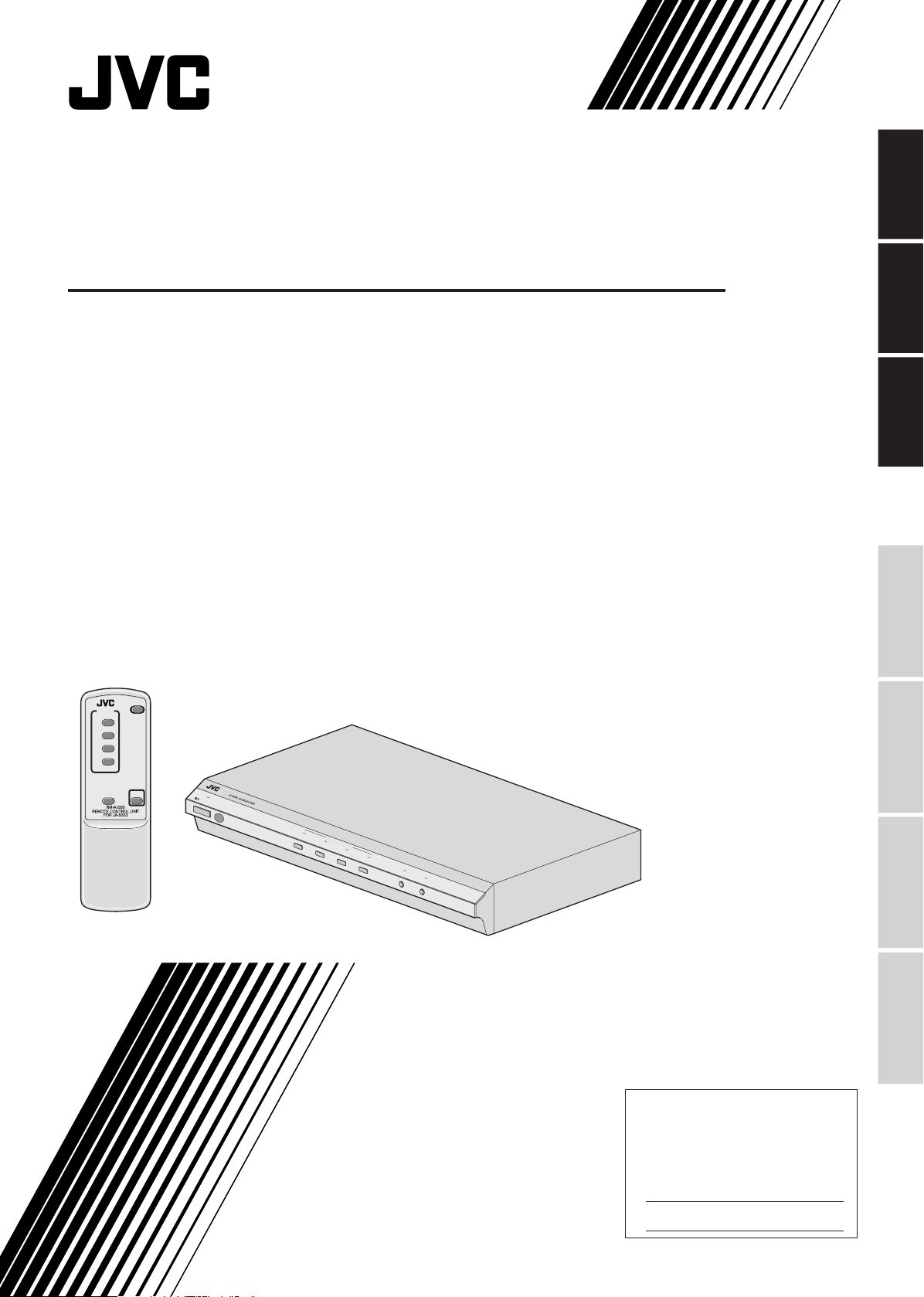
AV SELECTOR
SELECTEUR AV
SELECTOR AV
JX-S333
ENGLISH
FRANÇAIS
ESPAÑOL
INTRODUCTION
BASIC OPERATION
ADVANCED
OPERATION
INSTRUCTIONS
MANUEL D’INSTRUCTIONS
MANUAL DE INSTRUCCIONES
For Customer Use:
Enter below the Serial No. which is
located on the rear or bottom of
cabinet. Retain this information for
future reference.
OTHERS
Model No. JX-S333
Serial No.
LNT0042-001A
Page 2

Safety Information
FCC INFORMATION
This device complies with Part 15 of the FCC Rules. Operation
is subject to the following two conditions:
(1) This device may not cause harmful interference.
(2) This device must accept any interference received,
including interference that may cause undesired operation.
Note: This equipment has been tested and found to comply
with the limits for a Class B digital device, pursuant to
Part 15 of the FCC rules. These limits are designed to
provide reasonable protection against harmful
interference in a residential installation. This equipment
generates, uses and can radiate radio frequency
energy and, if not installed and used in accordance
with the instructions, it may cause harmful interference
to radio communications. However, there is no
guarantee that interference will not occur in a particular
installation. If this equipment dose cause harmful
interference to radio or television reception, which can
be determined by turning the equipment off and on,
the user is encouraged to try to correct the interference
by one or more of the following measures:
• Reorient or relocate the receiving antenna.
• Increase the separation between the equipment and receiver.
• Connect the equipment into an outlet on a circuit different
from that to which the receiver is connected.
• Consult the dealer or an experienced radio/TV technician
for help.
WARNING: TO REDUCE THE RISK OF
FIRE OR ELECTRIC SHOCK, DO NOT
EXPOSE THIS APPLIANCE TO RAIN OR
MOISTURE.
CAUTION
RISK OF ELECTRIC SHOCK
DO NOT OPEN
CAUTION : TO REDUCE THE RISK OF ELECTRIC SHOCK,
REFER SERVICING TO QUALIFIED SERVICE PERSONNEL.
DO NOT REMOVE COVER (OR BACK).
NO USER SERVICEABLE PARTS INSIDE.
The lightning flash with arrowhead symbol, within
an equilateral triangle, is intended to alert the
user to the presence of uninsulated “dangerous
voltage” within the product's enclosure that may
be of sufficient magnitude to constitute a risk of
electric shock to persons.
The exclamation point within an equilateral
triangle is intended to alert the user to the
presence of important operating and
maintenance (servicing) instructions in the
literature accompanying the appliance.
CAUTION —Changes or modifications not approved by JVC
could void user’s authority to operate the
equipment.
Contact
Address: JVC AMERICAS CORP.,
1700 VALLEY ROAD, WAYNE, N.J. 07470
Telephone: (973) 315-5000
Thank you for purchasing this JVC product. Before you begin
operating this unit, please read the instructions carefully to be
sure you get the best possible performance. If you have any
questions, consult your JVC dealer.
CAUTION
To reduce the risk of electrical shocks , fire, etc.:
1. Do not remove screws, covers or cabinet.
2. Do not expose this appliance to rain or moisture.
* It may be unlawful to record or play back copyrighted material
without the consent of the copyright owner.
INFORMATION (for CANADA)
This Class B digital apparatus meets all requirements of
the Canadian Interference-causing Equipment Regulations.
RENSEIGNEMENT (Pour CANADA)
Cet appareil numérique de la classe B respecte toutes les
exigences du Réglement sur le matérier brouilleur du
Canada.
IMPORTANT
1. Installation
•
Select a place which is level, dry and neither too hot nor
too cold (between -5° C and 40° C/23° F and 104° F).
•
Keep away from direct sunlight.
•
Do not put it too close to a heater.
2. Power cord
•
Do not handle the power cord with wet hands!
•
Do not bend the power cord sharply.
•
When unplugging the power cord, do not pull on the cord,
Hold the plug itself and remove it from the AC outlet.
3. Malfunctions, etc.
•
There are no user serviceable parts inside. If anything
goes wrong, unplug the power cord and consult your
dealer.
•
Do not insert any metallic object.
•
Do not allow water to get inside.
2
-EN
Page 3
Contents
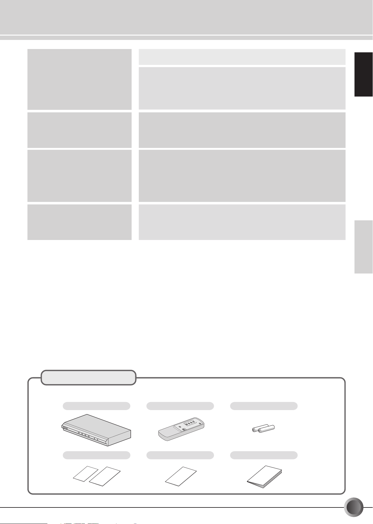
This unit (JX-S333)
Remote control unit (RM-AJ333)
Battery (AA) x 2
(for operation testing)
Warranty card
Registration card and Safety guide
Instruction Book (this book)
Safety Information ............................................................................................ 2
INTRODUCTION
BASIC OPERATION
ADVANCED OPERATION
OTHERS
Check the contents ..........................................................................................3
Major Features ................................................................................................. 4
System Configuration Example ........................................................................ 5
Connectors, Controls and Indicators ...............................................................6
Using the Remote Control Unit ........................................................................ 9
Watching Video .............................................................................................. 10
Dubbing (Multi-dubbing) ............................................................................... 12
Watching a Video Program While Recording Another One (Dubbing Lock) . 14
Centralized Management of Your Home Theater System .............................. 16
Useful Tips ..................................................................................................... 18
S-VIDEO input/output connectors .............................................................. 18
Component connectors .............................................................................. 18
S-video to component video conversion .................................................... 18
DUBBING LOCK function ........................................................................... 19
LINK function .............................................................................................. 20
Block Diagram ............................................................................................... 21
Troubleshooting .............................................................................................. 22
Specifications................................................................................................. 24
Glossary / Index ............................................................................................. 25
ENGLISH
Check the contents
Check the contents of the carton your JX-S333 came in. The following items should be found in the carton box:
INTRODUCTION
BASIC OPERATION
ADVANCED
OPERATION
OTHERS
EN-
3
Page 4
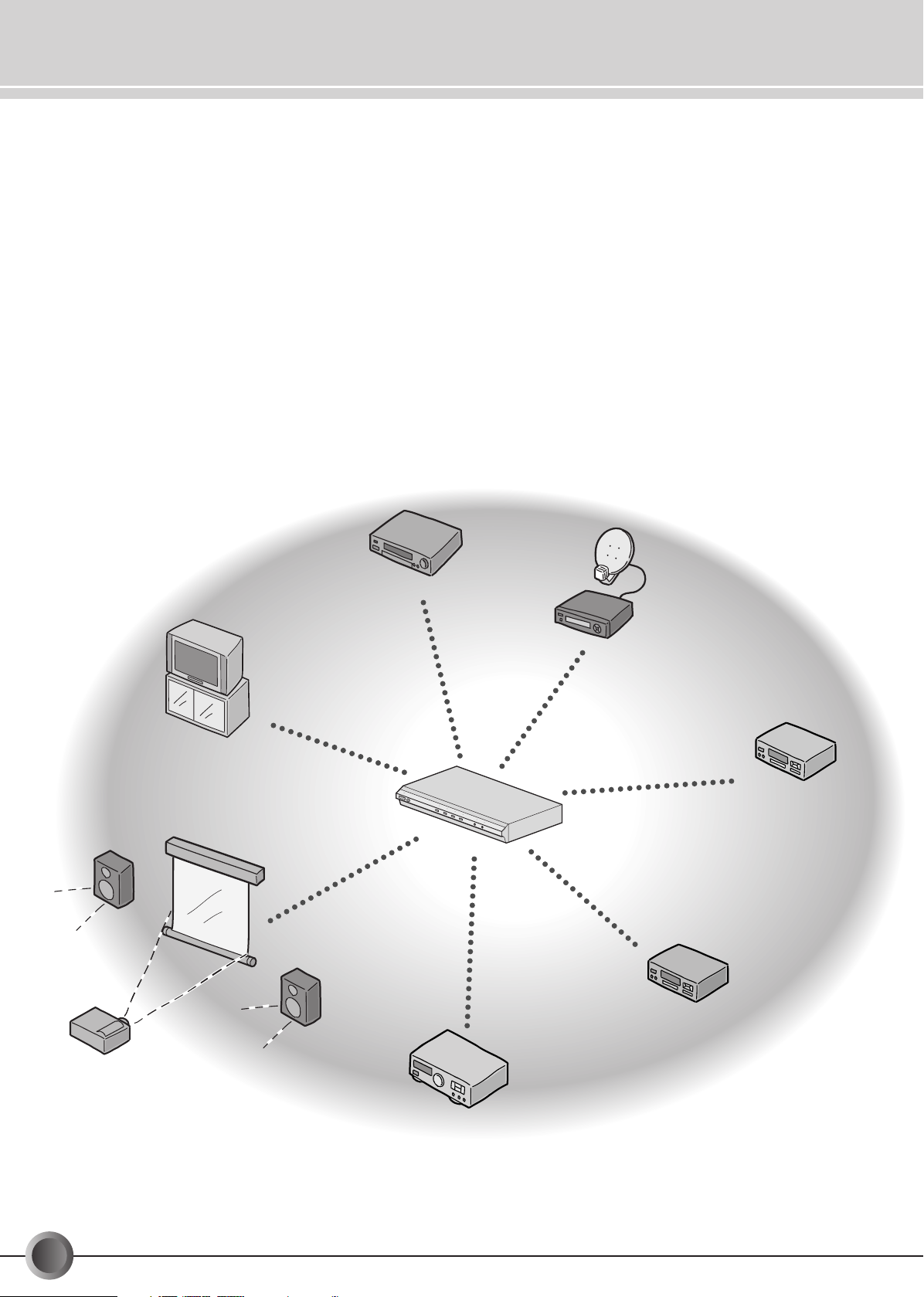
Major Features
TV monitor
VCR
DBS
tuner
AV
receiver
Projector
DVD
recorder
DVD
player
• Video signal converter (S-video to component video signals) is incorporated.
•Various input/output connectors—four input connectors (S-video/component video), two output
connectors (S-video), and one monitor output (S-video/component video) give you the centralized
management of your home theater system.
•A dubbing lock function permits the monitoring of a source while dubbing another source.
• Signal transmission with little signal deterioration for high picture quality. (The component video
circuitry is compatible with 30 MHz.)
•Automatic Power On/Off, linked with incoming S-video signals from the playback components.
4
-EN
Page 5
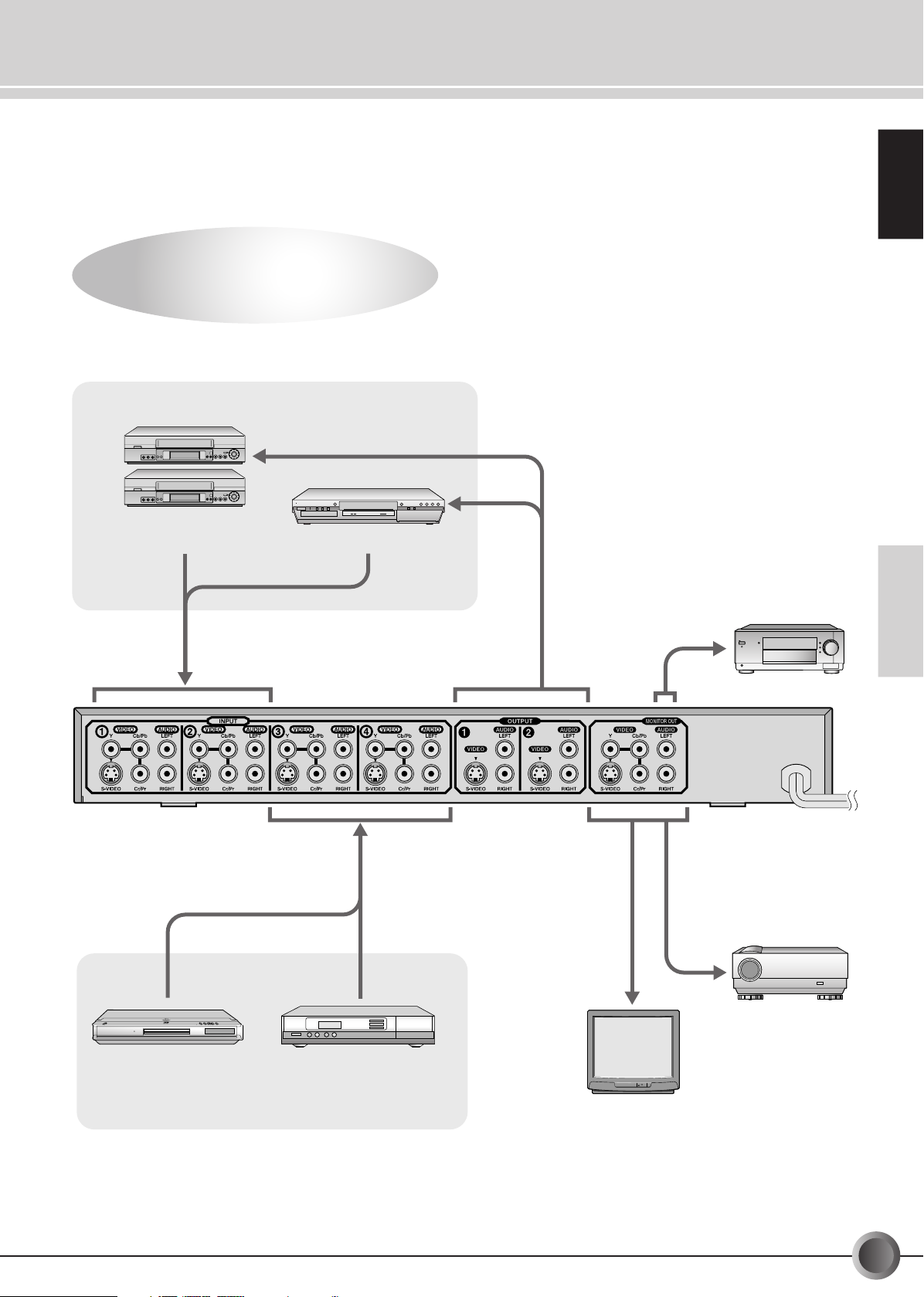
System Configuration Example
POWER
The AV Selector Expands the
Dimensions of the AV World.
The AV Selector Expands the
Dimensions of the AV World.
Recording components
VCRs
(S-VHS/VHS)
DVD recorder
ENGLISH
DVD player DBS tuner
Playback components
TV monitor
INTRODUCTION
AV receiver
Projector
BASIC OPERATION
ADVANCED
OPERATION
OTHERS
EN-
5
Page 6
Connectors, Controls and Indicators
ST
AND
BY/ON
1
2
3
4
DU
B
BIN
G LOC
K
L
IN
K
SOUR
CE SELECT
(MONITOR SELECT)
1
2
3
4
DUBBING LOCK
LINK
SOURCE SELECT
STANDBY/ON
(MONITOR SELECT)
54 67
12 3
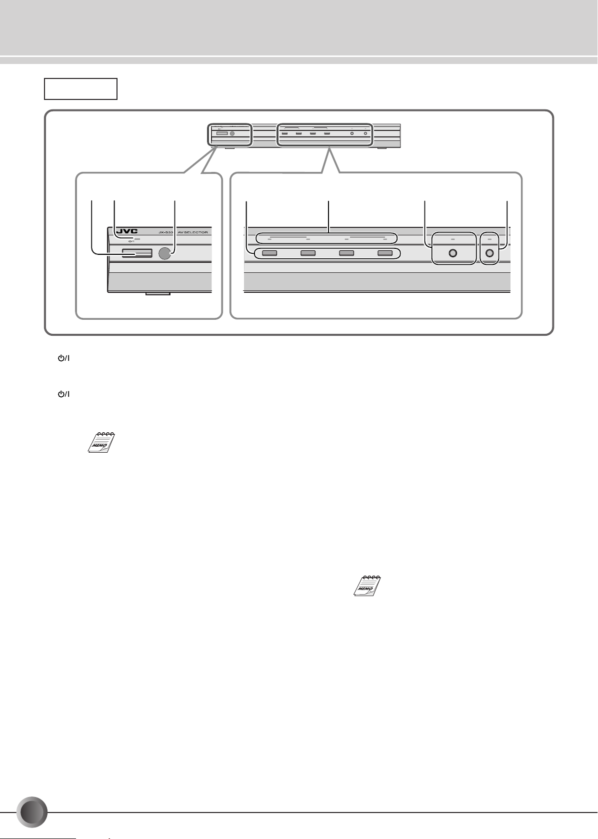
Front View
STANDBY/ON button
1
Press to turn the power ON or OFF (in standby mode).
STANDBY/ON indicator
2
This indicator lights in green when the power is ON, while
it lights in red when the power is OFF (in standby mode).
If the power has been switched OFF to
the Standby mode and then ON again, it
can be operated using the same settings
as when the power was switched OFF.
Remote sensor window
3
Aim at this when operating from the remote control unit.
SOURCE SELECT buttons (
4
p. 11, 13, 15, 17)
☞
Press to select an input component.
SOURCE SELECT indicators
5
(☞ p. 11, 13, 15, 17)
The indicator of the input component selected by the
SOURCE SELECT button lights in red.
DUBBING LOCK button/indicator (
6
(MONITOR SELECT)
p. 15, 17)
☞
Press to fix the output signals through the OUTPUT 1 and
2 connectors. This can prevent accidental or erroneous
operation during dubbing. The indicator lights in red when
DUBBING LOCK is activated.
• When one of the SOURCE SELECT buttons is pressed
while DUBBING LOCK is activated, only the video/audio
output through the MONITOR OUT is changed, but the
video/audio output through the OUTPUT 1 and 2
connectors remains unchanged so that you can keep
dubbing the signals through these connectors.
LINK button/indicator (
7
☞
p. 20)
Press to turn the LINK function ON or OFF.
When this function is ON, the indicator lights in red. The
unit power automatically turns on or off by detecting the
incoming S-video signals from the playback components.
This function is only available with the
playback components equipped with Svideo output connectors.
6
-EN
Page 7
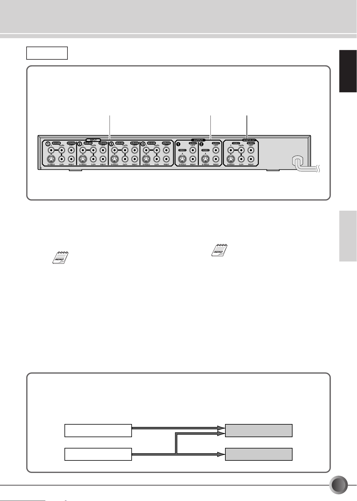
Rear view
231
ENGLISH
INPUT connectors (INPUT 1, 2, 3, 4)
1
Equipped with S-VIDEO/component video (Y, Cb/Pb, Cr/
Pr)/AUDIO.
Connect to the output connectors of the playback
components (up to four components).
Incoming S-video signals can be
converted and emitted through the
component video output of the MONITOR
OUT connectors.
OUTPUT connectors (OUTPUT 1, 2)
2
Equipped with S-VIDEO/AUDIO.
Connect to the input connectors of the recording
component (up to two components).
Video input/output signals
Video signals incoming from the INPUT connectors are emitted through the MONITOR OUT connectors as follows.
• Incoming S-video signals are emitted through both S-VIDEO jacks and the component video jacks.
• Incoming component signals are only emitted through the component video jacks.
MONITOR OUT connectors
3
Equipped with S-VIDEO/component video (Y, Cb/Pb, Cr/
Pr)/AUDIO.
Connect to the input connectors of the TV monitor.
S-video signals through the input
connectors are converted and emitted
through component video output of the
MONITOR OUT connectors.
INTRODUCTION
BASIC OPERATION
ADVANCED
OPERATION
OTHERS
Component
S-Video
Component
S-Video
EN-
7
Page 8
Connectors Controls, and Indicators (Remote Control Unit)
POWER
DUBBING LOCK
(MONITOR SELECT)
1
2
3
4
LINK
SOURCE
SELECT
43
1
2
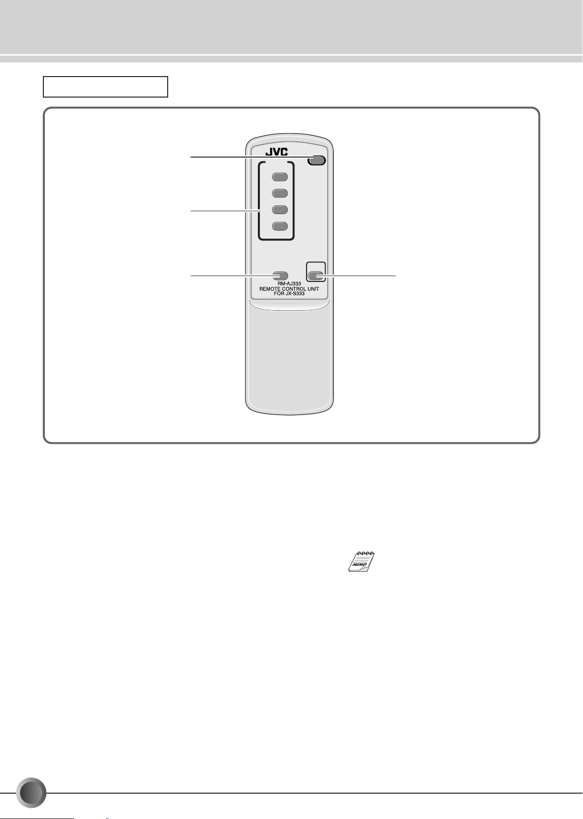
Remote Control Unit
1 POWER button
Press to turn the power ON or OFF (in standby mode).
SOURCE SELECT buttons (
2
Press to select an input component.
DUBBING LOCK button (
3
(MONITOR SELECT)
Press to fix the output signals through the OUTPUT 1 and
2 connectors. This can prevent accidental or erroneous
operation during dubbing. The DUBBING LOCK indicator
on the main unit lights in red when DUBBING LOCK is
activated.
• When one of the SOURCE SELECT buttons is pressed
while DUBBING LOCK is activated, only the video/audio
output through the MONITOR OUT is changed, but the
video/audio output through the OUTPUT 1 and 2
connectors remains unchanged so that you can keep
dubbing the signals through these connectors.
p. 11, 13, 15, 17)
☞
p. 15, 17)
☞
LINK button (
4
Press to turn the LINK function ON or OFF.
When this function is ON, the LINK indicator on the main
unit lights in red. The unit power automatically turns on or
off by detecting the incoming S-video signals from the
playback components.
p. 20)
☞
This function is only available with the
playback components equipped with SVIDEO output connectors.
8
-EN
Page 9

POWER
DUBBING LOCK
(MONITOR SELECT)
1
2
3
4
LINK
SOURCE
SELECT
S
T
A
N
D
B
Y
/O
N
1
2
3
4
DUBBING LOCK
LINK
SOURCE SELECT
(MONITOR SELECT)
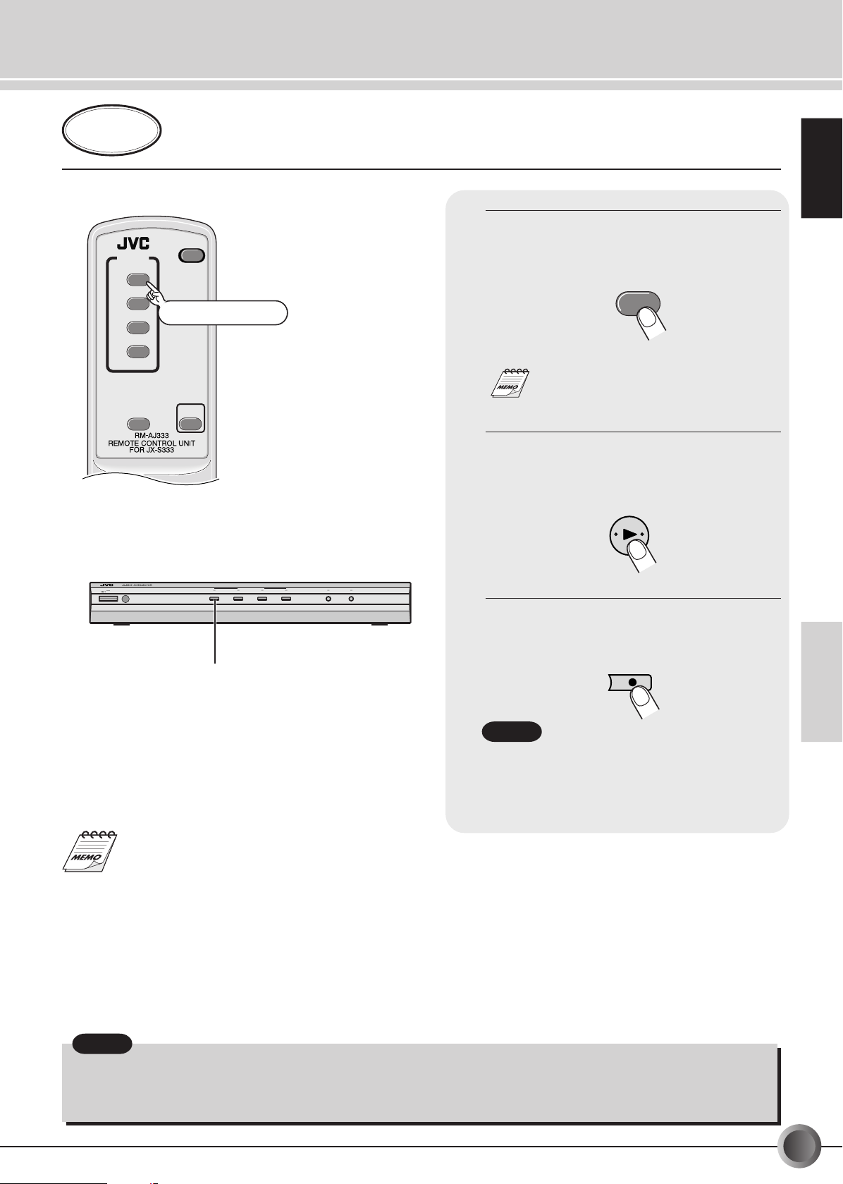
Using the Remote Control Unit
Battery Installation
Press the tab to remove the cover of the
battery compartment.
Notes:
Misuse of batteries could result in leakage. This could cause a fire or explosion.
To prevent this, pay special attention to the following points:
Battery
Precautions
1. Be sure to insert the batteries with correct positive “+” and negative “-” polarities.
2. Do not heat, disassemble or short-circuit batteries and never dispose of batteries by throwing them in a fire.
3. Do not use new and old batteries together.
• Also read the caution displayed on the battery when in use.
*The provided batteries are for checking operation only.
Insert two “AA”(R6, UM-3) dry-cell
batteries.
Replace the cover.
ENGLISH
Transmitted beam effective area
AV selector
Remote sensor
window
Approx. 60˚
Within 5 m
Notes:
• If the remote controllable distance between the
remote and main unit decreases, the batteries are
depleted and should be replaced with new ones
— (“AA”-size (R6/UM-3) batteries.
• JVC uses two types of the remote control signal
code for operating the AV selector—A and B. This
remote control unit can transmit B code signals.
INTRODUCTION
BASIC OPERATION
ADVANCED
OPERATION
OTHERS
Remote control unit
EN-
9
Page 10

Watching Video
Do not connect the AC power cord until all other connections have been made.
Connect a VCR to INPUT
• This shows an example of several possible connections. Also refer to the instruction books of the other components you are
using for operation and connection details.
(green)
(blue)
(red)
of the JX-S333 and watch the video played back on the VCR.
1
VCR (Playback deck)
(white)
(white)
(red)
(red)
:Signals
To S-VIDEO Output
To Component Video Output
(green)
(blue)
To AUDIO Output
(red)
(white)
To S-VIDEO Input
(red)
To AUDIO Input
(white)
(red)
JX-S333 rear panel
Connect to the OUTPUT connectors on the
JX-S333 so that the VCR can be used as a
recording machine.
To Component Video Input
(green)
(blue)
(red)
(white)
(red)
(green)
(blue)
(red)
To AUDIO Input
(white)
(red)
To S-VIDEO Input
TV monitor
Connection tips
• Before making any connections, turn off the power to all
components.
• It is not required to connect the components using both
S-VIDEO and component video connectors. To obtain the
best possible playback picture on the TV monitor, connect
the component using the component video connectors.
However, to use the LINK function (☞ P. 20), it is required
to connect the playback components through the S-VIDEO
connectors.
• If both the S-VIDEO and component video connectors are
connected between the components, the incoming signals
are emitted through the respective output connectors.
(☞ P. 7 “Video input/output signals”)
•Even though the playback components and the TV monitor
are connected through the different type of video
connectors (S-VIDEO/component video), you can watch
the playback picture. (☞ P. 7 “Video input/output signals”)
10
-EN
• The INPUT 1 and INPUT 2 connectors are used for
connecting the playback/recording components. Incoming
signals from the INPUT 1 and INPUT 2 connectors are
emitted through the MONITOR OUT connectors and at
the same time...
– Signals from the INPUT 1 connectors are emitted
through the OUTPUT 2 connectors.
– Signals from the INPUT 2 connectors are emitted
through the OUTPUT 1 connectors.
• The INPUT 3 and 4 connectors are used only for
connecting the playback components. Incoming signals
from these connectors are emitted through all the output
connectors at the same time. DO NOT connect the input
connectors of the components connected to these
connectors to any of the output connectors of the JX-S333.
Page 11

Press POWER (or STANDBY/
POWER
DUBBING LOCK
(MONITOR SELECT)
1
2
3
4
LINK
SOURCE
SELECT
S
TA
N
D
B
Y
/O
N
1
2
3
4
DUBBING
LOCK
LINK
SOU
RC
E SELECT
(MONITOR SELECT)
2
1
1
2
Tu r ning the power on
Selecting a VCR
POWER
1
PLAY
VCR
1.
ON on the main unit) to turn on
the JX-S333.
• The STANDBY/ON indicator lights in green.
Press SOURCE SELECT “1” to
2.
select VCR1.
• The indicator lights in red.
• If the SOURCE SELECT “1” indicator on
the JX-S333 is already lit, it is not required
to press the SOURCE SELECT “1” button.
Turn the TV monitor on and select
3.
the input.
•Turn the TV monitor on and select the input connected to the MONITOR OUT connectors on the
JX-S333.
ENGLISH
INTRODUCTION
• When you want to watch a video on another VCR, press the
SOURCE SELECT button to select the line number that the
VCR is connected to.
• Using the LINK function, you can turn on and off the power
to the JX-S333 by detecting the incoming S-video signals
(☞ P. 20).
Turn on the VCR’s power and start
4.
playback.
EN-
11
BASIC OPERATION
ADVANCED
OPERATION
OTHERS
Page 12

Dubbing (Multi-dubbing)
Do not connect the AC power cord until all other connections have been made.
You can dub a video program from VCR 1 to VCR 2 and vice versa.
This shows an example of several possible connections. Also refer to the instruction books of the other components you are using
for operation and connection details.
VCR1 (Playback component)
(green)
To S-VIDEO Output
To Component Video Output
(green)
(green)
(blue)
(blue)
(blue)
(red)
To AUDIO Output
(red)
(red)
(white)
(white)
(red)
(red)
To S-VIDEO Input
(red)
(white)
(white)
To AUDIO Input
(white)
(red)
(red)
(red)
JX-S333
rear panel
(white)
: Signals from VCR 1 to VCR 2
: Signals from VCR 2 to VCR 1
To Component Video Input
(green)
(blue)
(red)
(white)
(red)
(green)
(blue)
(red)
To AUDIO Input
(white)
(red)
TV monitor
(green)
(blue)
(red)
(red)
To Component Video Output
To S-VIDEO Output
To AUDIO Output
(white)
To S-VIDEO Input
VCR2 (Recording device)
Connection tips
• Before making any connections, turn off the power to all
components.
• It is not required to connect the components using both SVIDEO and component video connectors. To obtain the best
possible playback picture on the TV monitor, connect the
component using the component video connectors.
However, to dub the tapes, it is required to connect the
playback components through the S-VIDEO connectors.
• If both the S-VIDEO and component video connectors are
connected between the components, the incoming signals
are emitted through the respective output connectors.
(☞ P. 7 “Video input/output signals”)
12
-EN
(red)
To AUDIO Input
To S-VIDEO Input
(white)
• The INPUT 1 and INPUT 2 connectors are used for
connecting the playback/recording components. Incoming
signals from the INPUT 1 and INPUT 2 connectors are
emitted through the MONITOR OUT connectors and at
the same time...
– Signals from the INPUT 1 connectors are emitted
through the OUTPUT 2 connectors.
– Signals from the INPUT 2 connectors are emitted
through the OUTPUT 1 connectors.
Page 13
Preparation
POWER
DUBBING LOCK
(MONITOR SELECT)
1
2
3
4
LINK
SOURCE
SELECT
S
T
A
N
D
B
Y
/O
N
1
2
3
4
DUBBING
LOCK
LINK
SOU
RCE SELECT
(MONITOR SELECT)
1
1
Selecting VCR 1
1
PLAY
VCR 1
REC
VCR 2
•Turn on the power to the JX-S333.
•
Tu rn on the TV monitor and select the input connected to the MONITOR OUT connectors on the JX-S333.
•Turn on the power to VCRs to prepare for dubbing.
Press SOURCE SELECT “1” to select
1.
VCR1 as the source component.
• The indicator lights in red.
• If the SOURCE SELECT “1” indicator on
the JX-S333 is already lit, it is not required
to press the SOURCE SELECT “1” button.
Play back a tape on VCR 1.
2.
ENGLISH
To prevent erroneous operation during dubbing, press the
DUBBING LOCK button to activate the DUBBING LOCK function
(☞ P. 19).
Start recording on VCR 2.
3.
Notes:
Notes
• Set the input switch on the recording VCR to the
external input mode (AUX) when dubbing.
• Set the recording VCR to S-VIDEO input when
using an S-VIDEO input connector for recording.
INTRODUCTION
BASIC OPERATION
ADVANCED
OPERATION
OTHERS
Notes:
• Some video software may contain signals to prevent it from being copied. If you try to copy such a program, the results will not
be viewable.
• Recording of copyrighted material for purposes other than personal use is illegal without permission of the copyright holder.
EN-
13
Page 14

Watching a Video Program While Recording Another One
(Dubbing Lock)
Do not connect the AC power cord until all other connections have been made.
Connect the playback VCR (VCR 1) to the INPUT 1, and the recording VCR (VCR 2) to the OUTPUT
2. In addition, connect the DBS tuner to the INPUT 4.
• With these connections, you can dub a tape while watching the DBS program.
This shows an example of several possible connections. Also refer to the instruction books of the other components you are using
for operation and connection details.
VCR1 (Playback deck)
(green)
To S-VIDEO Output
To Component Video Output
(green)
(blue)
(blue)
(red)
To AUDIO Output
(red)
(white)
(white)
(red)
To S-VIDEO Input
(red)
(white)
To AUDIO Input
(white)
Playback picture
(red)
(red)
Program picture
DBS tuner
• Connect to the OUTPUT 1
connectors on the JX-S333 so
that VCR 1 can be used as a
recording machine. (Connect
the output connectors on VCR
2 to the INPUT 2 connectors
on the JX-S333.)
JX-S333
rear panel
To Component Video Input
(green)
(blue)
(red)
(green)
(blue)
(red)
(white)
To AUDIO Output
(white)
(red)
To S-VIDEO Output
(red)
(red)
(red)
(white)
(white)
To S-VIDEO Input
To AUDIO Input
(green)
To S-VIDEO Output
(green)
To Component Video Output
(blue)
(blue)
(red)
(red)
To AUDIO Output
VCR2 (Recording deck)
Connection tips
• Before making any connections, turn off the power to all
components.
• The INPUT 1 and INPUT 2 connectors are used for
connecting the playback/recording components. Incoming
signals from the INPUT 1 and INPUT 2 connectors are
emitted through the MONITOR OUT connectors and at the
same time...
–Signals from the INPUT 1 connectors are emitted through
the OUTPUT 2 connectors.
–Signals from the INPUT 2 connectors are emitted through
the OUTPUT 1 connectors.
14
-EN
(red)
(white)
(red)
(white)
Recording picture
(white)
(red)
To AUDIO Input
(white)
(red)
To S-VIDEO Input
TV monitor
Program picture
: Flow of VCR1 signal
: Flow of DBS signal
• The INPUT 3 and 4 connectors are used only for
connecting the playback components. Incoming signals
from these connectors are emitted through all the output
connectors at the same time. DO NOT connect the input
connectors of the components connected to these
connectors to any of the output connectors of the JX-S333.
• It is not required to connect the components using both SVIDEO and component video connectors. To obtain the
best possible playback picture on the TV monitor, connect
the component using the component video connectors.
However, to dub the tapes, it is required to connect the
playback components through the S-VIDEO connectors.
Page 15

Preparation
POWER
DUBBING LOCK
(MONITOR SELECT)
1
2
3
4
LINK
SOURCE
SELECT
S
TA
N
D
B
Y
/O
N
1
2
3
4
DUBBING LOCK
LINK
SOU
RCE SELECT
(MONITOR SELECT)
1 5 4
5
Selecting DBS tuner
4
Set the dubbing lock mode
1
Selecting VCR 1
1
PLAY
REC
DUBBING LOCK
( MONITOR SELECT )
4
•Turn on the power to the JX-S333.
•
Tu rn on the TV monitor and select the input connected to the MONITOR OUT connectors on the JX-S333.
•Turn on the power to all other connected components.
Press SOURCE SELECT “1” to select
1.
VCR1 as the source component.
• The indicator lights in red.
• If the SOURCE SELECT “1” indicator on
the JX-S333 is already lit, it is not required
to press the SOURCE SELECT “1” button.
Start playback of VCR1.
2.
• The VCR1 playback video is displayed on the TV
monitor screen.
PLAYPlayback video
ENGLISH
To exit from dubbing lock mode:
• Press DUBBING LOCK again.
• When the input source is changed by pressing one of the
SOURCE SELECT buttons in the dubbing lock mode, the video
displayed on the TV monitor connected to the MONITOR OUT
connectors can be changed without affecting the video being
dubbed.
Start recording of VCR2.
3.
Press DUBBING LOCK to set the
4.
dubbing lock mode.
• The indicator lights in red.
Press SOURCE SELECT “4” to
5.
watch the video of the DBS.
• The SOURCE SELECT “4” indicator lights in red.
• The DBS video is displayed on the TV monitor
screen.
DBS video
INTRODUCTION
BASIC OPERATION
ADVANCED
OPERATION
OTHERS
Note:
While the DUBBING LOCK function is activated, the power cannot be turned off and the LINK button does not work.
15
EN-
Page 16

Centralized Management of Your Home Theater System
S
TAN
D
BY
/ON
1
2
3
4
DUBBING LOCK
LINK
S
O
U
R
C
E
S
E
L
E
C
T
(MONITOR SELECT)
POWER
Do not connect the AC power cord until all other connections have been made.
You can watch the DVD playback picture through your home theater system while dubbing the
tapes on the VCRs.
This shows an example of several possible connections. Also refer to the instruction books of the other components you are using
for operation and connection details.
Center speaker
Screen
Front speaker
AV receiver
Projector
Front speaker
Surround speakerSurround speaker
VCR 2
From AUDIO Out of
MONITOR OUT
To S-VIDEO/Component video/
AUDIO Input of INPUT 3
DVD Player
Connection tips
Before making any connections, turn off the power to all
components.
From S-VIDEO/
Component Out of
MONITOR OUT
JX-S333
From S-VIDEO/AUDIO
Out of OUTPUT 2
To S-VIDEO/AUDIO
Input of INPUT 1
VCR 1
In order to enjoy multi-channel surround sound
through the DVD player, connect directly DVD
player and the AV receiver through the digital audio
connectors.
16
-EN
Page 17

Preparation
POWER
DUBBING LOCK
(MONITOR SELECT)
1
2
3
4
LINK
SOURCE
SELECT
S
TA
N
D
B
Y
/O
N
1
2
3
4
DUBBING LOCK
LINK
SOU
RCE SELECT
(MONITOR SELECT)
1 5 4
5
Selecting DVD player
4
Set the dubbing lock mode
1
Selecting VCR 1
1
PLAY
REC
DUBBING LOCK
( MONITOR SELECT )
3
•Turn on the power to the JX-S333.
•
Tu rn on the TV monitor and select the input connected to the MONITOR OUT connectors on the JX-S333.
•Turn on the power to all other connected components.
Press SOURCE SELECT “1” to select
1.
VCR1 as the source component.
• The indicator lights in red.
• If the SOURCE SELECT “1” indicator on
the JX-S333 is already lit, it is not required
to press the SOURCE SELECT “1” button.
Start playback of VCR1.
2.
• The VCR1 playback video is displayed on the TV
monitor screen.
PLAYPlayback video
ENGLISH
To exit from dubbing lock mode:
• Press DUBBING LOCK again.
• When the input source is changed by pressing one of the
SOURCE SELECT buttons in the dubbing lock mode, the
video displayed on the TV monitor connected to the MONITOR OUT connectors can be changed without affecting the
video being dubbed.
Notes:
• Some video software may contain signals to prevent it from being copied. If you try to copy such a program, the results will not
be viewable.
• Recording of copyrighted material for purposes other than personal use is illegal without permission of the copyright holder.
• While the DUBBING LOCK function is activated, the power cannot be turned off and the LINK button does not work.
Start recording of VCR2.
3.
INTRODUCTION
Press DUBBING LOCK to set the
4.
dubbing lock mode.
• The indicator lights in red.
BASIC OPERATION
Press SOURCE SELECT “3” to
5.
watch the playback picture
ADVANCED
OPERATION
through the DVD player.
• The SOURCE SELECT “3” indicator lights in red.
• The playback picture through the DVD player is
displayed on the TV monitor screen.
DBS video
EN-
OTHERS
17
Page 18

Useful Tips
S-VIDEO input/output connectors
• The S-VIDEO input/output connectors are those for the
Y/C (luminance/chrominance) separate video signals.
Component connectors
• Component connection is recommended when connecting
a DVD player or DBS tuner (equipped with component input
connectors) to a TV monitor.
Since a DVD disc is encoded with a component video (Y
color difference) signal format it can reproduce better
quality color than the composite or S-video signal used in
a VCR.
With a component connection, the signal encoded on a
DVD disc can be output in its original form to maintain the
highest quality picture.
• If these connectors are connected to a VCR equipped
with S-VIDEO connectors, recording and playback of
clearer video becomes possible by reducing loss in the
video signal.
TV monitor
S-video to component video conversion
• JX-S333 is equipped with the S-video/component video
conversion circuitry which converts the incoming S-video
signals into component video signals and emits through
all component video output connectors.
Notes:
• If both the S-VIDEO and component video connectors
are connected between the components, the incoming
signals are emitted through the respective output
connectors. (☞ P. 7 “Video input/output signals”)
• The quality of the converted signals are equal to the
original S-video signal quality. Conversion process
never improve the picture quality.
This signal is
converted into
component
video signal.
DVD player DBS tuner
:Signals
S-video
cord
VCR without the component
Audio
cord
video output
Component
video cord
TV monitor with the
component video input
:Signals
Audio
cord
18
-EN
Page 19

DUBBING LOCK function
S
T
A
N
D
B
Y
/O
N
1
2
3
4
D
UB
B
IN
G LO
C
K
L
IN
K
SO
UR
CE SE
L
EC
T
(MONITOR SELECT)
• DUBBING LOCK button
Provides the dubbing lock function for prevention of accidental operational mistakes as well as
a monitor select function for watching a video program while recording another.
Dubbing lock function
ENGLISH
When the DUBBING LOCK button is pressed while the VCR
for recording is in use, the POWER (
STANDBY/ON) and
LINK buttons are disabled.
Also, even when the SOURCE SELECT button is pressed by
mistake, the dubbing lock function keeps the signal output
from the output connectors so that the recording of the VCR
can be continued.
Monitor select function
This function is most often used in “watching a video program
while recording another one”. Pressing the DUBBING LOCK
button during recording sets the dubbing lock mode, the user
can change the video displayed on the TV monitor screen
by pressing one of the SOURCE SELECT buttons.
(The SOURCE SELECT “1” and “3” indicators light in red.)
• Flow of monitor select function depending on
the DUBBING LOCK button
SOURCE SELECT 1
ON
OUTPUT 2 : VCR1 output
MONITOR output : VCR1 output
(Source 1)
(Source 1)
Operation available
Operation
disabled
by monitor select
function
DUBBING
LOCK ON
Player VCR1 Player VCR3
: Flow of VCR1 signal
: Flow of VCR3 signal
Video switched
by monitorselect function
Operation
disabled
INTRODUCTION
BASIC OPERATION
DUBBING LOCK
ON
OUTPUT 2 : VCR1 output
(Source 1)
MONITOR output : VCR1 output
Recorder VCR2 TV monitor
(Source 1)
ADVANCED
OPERATION
OUTPUT 2 : VCR1 output
SOURCE SELECT 3
ON
MONITOR output : VCR3 output
(Source 1)
(Source 3)
OTHERS
DUBBING LOCK
OFF
OUTPUT 2 : VCR1 output
MONITOR output : VCR1 output
(Source 1)
(Source 1)
EN-
19
Page 20

Useful Tips (continued)
STA
N
DB
Y/O
N
1
2
3
4
DUBBING LOCK
LINK
S
O
U
R
C
E
S
E
LE
C
T
(MONITOR SELECT)
(MONITOR SELECT)
LINK function
• Using the LINK function, you can turn on and off the power to the JX-S333 by detecting the
incoming S-video signals. Therefore, it is not required to turn on the power to the JX-S333
manually.
DVD Player
How to set the function
1Press one of the SOURCE SELECT buttons for which you
can set this function.
2Press LINK to activate the LINK function for the selected
playback component.
The LINK indicator lights in red.
To cancel the function, press LINK again.
The LINK indicator goes off.
When S-video signals
are emitted...
How the function actually works
When the JX-S333 detects incoming signal through the
playback source for which the LINK function is activated,
the power comes on automatically.
When incoming signal stops, the power goes off.
Notes:
•To use the LINK function, the playback components
should be connected to the JX-S333 using the SVIDEO connectors. If connected using the component
video connectors, this does not function.
• If you do not use the LINK function, deactivate the
function by pressing LINK (the indicator goes off), then
turn on the power to the JX-S333.
To activate the function, press LINK again.
• While the DUBBING LOCK function is in use, the LINK
button does not work.
To cancel the LINK function, first cancel the DUBBING
LOCK function.
S-video signals
Component signals
JX-S333
JX-S333 automatically turns on by detecting the incoming S-video signals.
(When the signals stop, the power also turns off.)
20
-EN
Page 21

AUDIOINPUT1
AUDIOINPUT2
AUDIOINPUT3
AUDIOINPUT4
S-VIDEOINPUT1
S-VIDEOINPUT2
S-VIDEOINPUT3
S-VIDEOINPUT4
OUTPUT~
OUTPUTŸ
MONITOR OUT
MONITOR OUT
COMPONENTINPUT1
COMPONENTINPUT2
COMPONENTINPUT3
COMPONENTINPUT4
OUTPUT~
OUTPUTŸ
INPUT AMP
SOURCE
SELECT
SOURCE
SELECT
AUDIO
S-VIDEO
AUDIO
(MONITOR)
S-VIDEO
(MONITOR)
COMPONENT
(MONITOR)
OUTPUT AMP
OUTPUT AMP
OUTPUT
SELECT
OUTPUT AMP
S-VIDEO/COMPONENT
SELECT
S-VIDEO/COMPONENT
CONVERSION
6 dB
6 dB
6 dB
AUDIO
AUDIO
S-VIDEO
AUDIO
S-VIDEO
MONITOR OUT
COMPONENT
S-VIDEO
Block Diagram
ENGLISH
INTRODUCTION
BASIC OPERATION
ADVANCED
OPERATION
OTHERS
21
EN-
Page 22

Troubleshooting
• The JX-S333 incorporates a microcomputer, which may malfunction due to external interference
or noise. If this trouble cannot be resolved by checking the items in the following table, reset the
microcomputer by turning off the JX-S333, unplugging its power cord from the wall outlet, plugging it in again and then checking the operation.
Symptom PageCause Remedy
Power No power.
•Is the power cord disconnected from
the AC outlet?
•Insert the power plug firmly into the AC
outlet.
—
Playback
Recording
Unit cannot be turned
OFF.
Power goes off soon
after it has been
turned on.
Required
picture won’t appear.
No picture recorded
on the edited tape.
•Make sure that the DUBBING LOCK
function is set to ON.
•Is the LINK function activated?
•Is the required video component
connected to the corresponding
INPUT/OUTPUT connectors correctly?
•Is the TV monitor connected to the
MONITOR OUT connectors correctly?
•Are the playback and recording VCRs
connected correctly to the INPUT/
OUTPUT connectors? Also, is the
correct SOURCE SELECT button
selected?
• Is the DUBBING LOCK function set?
•Is the input select switch on the
recording VCR set to the “AUX”
position?
•Is the video input select switch on the
recording VCR with S-VIDEO
connectors set to the “S-VIDEO IN”
position or “VIDEO input” position?
•Press the POWER button after setting
the DUBBING LOCK function OFF.
•Turn on the playback component for
which the LINK function is activated.
Then deactivate the function.
•Check the connections again and
reconnect correctly.
•Check the connections again and
reconnect correctly.
•Check the connections again and
reconnect correctly before selecting
the correct SOURCE SELECT button.
•Press DUBBING LOCK to OFF before
pressing a SOURCE SELECT button.
•Set the input select switch on the
recording VCR to “AUX”.
•Set the video input switch on the
recording VCR to the correct position.
•Some video software may contain
signals to prevent it from being copied.
If you try to copy such a program, the
results will not be viewable.
19
20
10, 14
10, 14
12, 13
15, 17
13
13
—
22
-EN
Dubbing operations
are not possible when
using equipment
connected to the
component connector.
No sound recorded
on the edited tape.
•Are the S-VIDEO connectors also
connected?
•Are the video components etc.
connected to the AUDIO input
connectors correctly?
•Component video signals cannot be
converted into S-video signals.
Connect the components using the SVIDEO connectors for dubbing.
•Check the connections again and
reconnect correctly.
12, 14
12, 14
Page 23

Symptom PageCause Remedy
ENGLISH
Watching No picture displayed
on TV monitor.
No picture displayed
on TV monitor with
component input.
Other The LINK function
does not work.
Remote control not
working.
•Is the SOURCE SELECT button for
the source component selected
correctly?
•Is the TV monitor connected properly
to the MONITOR OUT connector?
•Is the TV monitor’s input selector set
correctly?
•Is a TV monitor with a component input
connected and set correctly?
•
Are the S-VIDEO connectors connected?
•Are the remote control batteries
exhausted?
•Are the batteries inserted with correct
polarity ( + and – )?
•Check the pressed SOURCE SELECT
button and press the correct button.
•Check the connection and connect it
properly.
•Check the TV monitor’s input selector.
•Check the component input connection
by referring to the TV monitor’s
instruction manual.
•Connect the components using the SVIDEO connectors to use the LINK
function.
•Replace both batteries with new ones.
•Insert them correctly.
10
10
11
10, 12
14, 16
20
9
9
INTRODUCTION
BASIC OPERATION
ADVANCED
OPERATION
OTHERS
EN-
23
Page 24

Specifications
Design and specifications subject to change without notice.
Product name
Input/output connectors
Video inputs
Video outputs
(Reference level)
Video crosstalk
Video S/N ratio
Video frequency response
Audio inputs
Audio outputs
Audio crosstalk
Audio S/N ratio
Audio frequency response
Distortion
Power requirements
Power consumption
Dimensions
AV selector
Inputs: 4 lines (Component, S-VIDEO, AUDIO L/R) x 4
Outputs: 2 lines (S-VIDEO, AUDIO L/R) x 2
Monitor outputs: 1 line (Component, S-VIDEO, AUDIO L/R) x 1
Reference level
• S-VIDEO Y: Vp-p = 1.0 V (75 Ω)
C: Vp-p = Burst 0.286 V/ Cyan 0.642 V (75 Ω)
• Component signals
Y: Vp-p = 1.0 V (75 Ω)
Cb/Pb: Vp-p = 0.7 V (75 Ω)
Cr/Pr: Vp-p = 0.7 V (75 Ω)
Maximum input
• S-VIDEO V: Vp-p = 1.5 V (75 Ω)
C: Vp-p = Burst 0.429 V/ Cyan 0.963 V (75 Ω)
• Component signals
Y: Vp-p = 1.5 V (75 Ω)
Cb/Pb: Vp-p = 1.05 V (75 Ω)
Cr/Pr: Vp-p = 1.05 V (75 Ω)
• S-VIDEO Y: Vp-p = 1.0 V (75 Ω)
C: Vp-p = Burst 0.286 V/ Cyan 0.642 V (75 Ω)
• Component signals
Y: Vp-p = 1.0 V (75 Ω)
Cb/Pb: Vp-p = 0.7 V (75 Ω)
Cr/Pr: Vp-p = 0.7 V (75 Ω)
50 dB or more (45 dB or more between Y/C and Y/Pb/Pr in the same channel)
50 dB or more
S-VIDEO: 10 MHz, Component signals: 30 MHz
Reference level: –10 dBV (47 kΩ)
Maximum level: +6 dBV (1 kHz, 1% distortion)
–10 dBV (with reference input, 1 kHz)
80 dB or more (1 kHz)
80 dB or more
5 Hz to 50 kHz
Less than 0.03% (with reference input, 1 kHz)
AC 120 V `, 60 Hz
6 W (less than 2.0 W in standby mode)
(W) 435 mm x (H) 64 mm x (D) 282 mm (including knobs, jacks, and feet)
(17-3/16" x 2-9/16" x 11-1/8")
Main body weight
Accessories
24
-EN
2.4 kg (5.3 lbs)
Remote control unit (RM-AJ333), “AA” (R6/UM-3) battery x 2 (for operation testing)
Page 25

Glossary / Index
Multi-dubbing
Capability of using more than one VCR for dubbing by
selecting any of them as the player and recorder.
S-VIDEO signal
Signal obtained by separating the composite video signal
into the luminance and chrominance signals. This makes
the video clearer with fewer blurs in the colors.
Composite video signal
Signal composed of the luminance (Y) and chrominance
(C) signals of the S-Video signals.
Component connectors
Means for transmission of high-quality video signals (Y/
Pb/Pr and Y/Cb/Cr) from a DVD player, etc. to a
high-performance video monitor without interference
between the signal components.
Terms
A
AUDIO...................................................... 10, 12, 14
ENGLISH
C
Component connectors ............................ 10, 12, 14
D
DUBBING LOCK ...................................... 15, 17, 19
L
LINK ........................................................................ 20
M
Multi-dubbing .......................................................... 12
S
STANDBY ................................................................. 6
SOURCE SELECT .......................... 11, 13, 15, 17
S-video signal .......................................... 10, 12, 14
INTRODUCTION
BASIC OPERATION
ADVANCED
OPERATION
OTHERS
EN-
25
Page 26

2005 Victor Company of Japan, Limited
Printed in Japan©
 Loading...