

Page 1
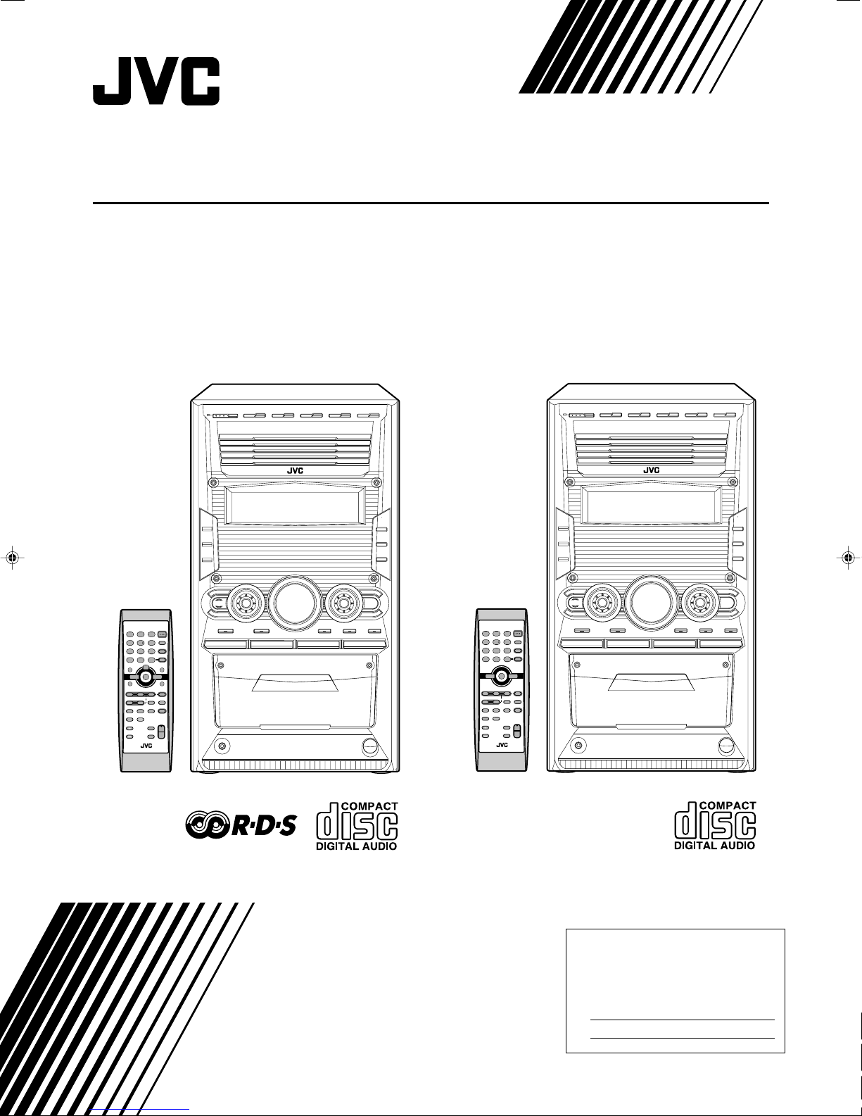
COMPACT COMPONENT SYSTEM
CA-HXZ10
INSTRUCTIONS
For Customer Use:
Enter below the Model No. and Serial No.
which are located either on the rear, bottom or side of the cabinet. Retain this
information for future reference.
Model No.
Serial No.
GVT0100-008B
[B, A]
Page 2
Warnings, Cautions and Others
15 cm
15 cm
15 cm
15 cm
15 cm
10 cm
1 cm
1 cm
CA-HXZ10
IMPORTANT for the U.K.
DO NOT cut off the mains plug from this equipment. If the plug
fitted is not suitable for the power points in your home or the
cable is too short to reach a power point, then obtain an appropriate safety approved extension lead or consult your dealer.
BE SURE to replace the fuse only with an identical approved
type, as originally fitted.
If nonetheless the mains plug is cut off ensure to remove the fuse
and dispose of the plug immediately, to avoid a possible shock
hazard by inadvertent connection to the mains supply.
If this product is not supplied fitted with a mains plug then follow
the instructions given below:
IMPORTANT:
DO NOT make any connection to the terminal which is marked
with the letter E or by the safety earth symbol or coloured green
or green-and-yellow.
The wires in the mains lead on this product are coloured in
accordance with the following code:
Blue : Neutral
Brown : Live
As these colours may not correspond with the coloured markings
identifying the terminals in your plug proceed as follows:
The wire which is coloured blue must be connected to the
terminal which is marked with the letter N or coloured black.
The wire which is coloured brown must be connected to the
terminal which is marked with the letter L or coloured red.
IF IN DOUBT - CONSULT A COMPETENT ELECTRICIAN.
Caution–– (standby/on) button!
Disconnect the mains plug to shut the power off completely (all
lamps and indications go off). The (standby/on) button in any
position does not disconnect the mains line.
• When the unit is on standby, the STANDBY lamp lights red.
• When the unit is turned on, the STANDBY lamp goes off.
The power can be remote controlled.
Caution
To reduce the risk of electrical shocks, fire, etc.:
1. Do not remove screws, covers or cabinet.
2. Do not expose this appliance to rain or moisture.
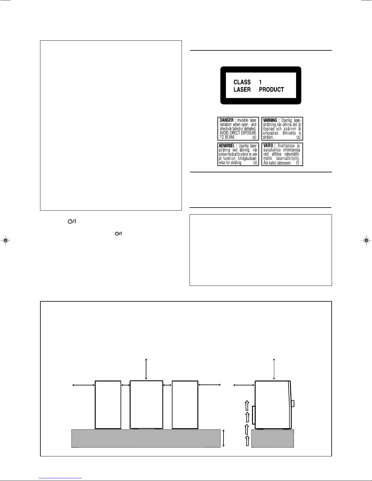
IMPORTANT FOR LASER PRODUCTS
REPRODUCTION OF LABELS
1 CLASSIFICATION LABEL, PLACED ON REAR ENCLOSURE
2 WARNING LABEL, PLACED INSIDE THE UNIT
1. CLASS 1 LASER PRODUCT
2. DANGER: Invisible laser radiation when open and interlock failed
or defeated. Avoid direct exposure to beam.
3. CAUTION: Do not open the top cover. There are no user
serviceable parts inside the Unit; leave all servicing to qualified
service personnel.
CAUTION
• Do not block the ventilation openings or holes.
(If the ventilation openings or holes are blocked by a
newspaper or cloth, etc., the heat may not be able to get out.)
• Do not place any naked flame sources, such as lighted
candles, on the apparatus.
• When discarding batteries, environmental problems must be
considered and local rules or laws governing the disposal of
these batteries must be followed strictly.
• Do not expose this apparatus to rain, moisture, dripping or
splashing and that no objects filled with liquids, such as vases,
shall be placed on the apparatus.
Caution: Proper Ventilation
To avoid risk of electric shock and fire, and to prevent damage, locate the apparatus as follows:
1 Front:
No obstructions and open spacing.
2 Sides/ Top/ Back:
No obstructions should be placed in the areas shown by the dimensions below.
3 Bottom:
Place on the level surface. Maintain an adequate air path for ventilation by placing on a stand with a height of 10 cm or more.
Front view
Side view
– G-1 –
Page 3

✮✮✮✮✮✮✮✮✮✮✮✮✮✮✮✮✮✮✮✮✮✮✮✮✮✮✮✮✮✮✮✮✮✮✮✮✮✮✮✮✮✮✮✮✮✮✮
✮✮✮✮✮✮✮✮✮✮✮✮✮✮✮✮✮✮✮✮✮✮✮✮✮✮✮✮✮✮✮✮✮✮✮✮✮✮✮✮✮✮✮✮✮✮✮
SAFETY INSTRUCTIONS
“SOME DOS AND DON’TS ON THE SAFE USE OF EQUIPMENT”
This equipment has been designed and manufactured to meet international safety standards but, like any electrical equipment,
care must be taken if you are to obtain the best results and safety is to be assured.
Do read the operating instructions before you attempt to use the equipment.
Do ensure that all electrical connections (including the mains plug, extension leads and interconnections between pieces of equipment)
are properly made and in accordance with the manufacturer’s instructions. Switch off and withdraw the mains plug when making or
changing connections.
Do consult your dealer if you are ever in doubt about the installation, operation or safety of your equipment.
Do be careful with glass panels or doors on equipment.
DON’T continue to operate the equipment if you are in any doubt about it working normally, or if it is damaged in any way — switch
off, withdraw the mains plug and consult your dealer.
DON’T remove any fixed cover as this may expose dangerous voltages.
DON’T leave equipment switched on when it is unattended unless it is specifically stated that it is designed for unattended operation
or has a standby mode.
Switch off using the switch on the equipment and make sure that your family know how to do this.
Special arrangements may need to be made for infirm or handicapped people.
DON’T use equipment such as personal stereos or radios so that you are distracted from the requirements of traffic safety. It is
illegal to watch television whilst driving.
DON’T listen to headphones at high volume as such use can permanently damage your hearing.
DON’T obstruct the ventilation of the equipment, for example with curtains or soft furnishings.
Overheating will cause damage and shorten the life of the equipment.
DON’T use makeshift stands and NEVER fix legs with wood screws — to ensure complete safety always fit the manufacturer’s
approved stand or legs with the fixings provided according to the instructions.
DON’T allow electrical equipment to be exposed to rain or moisture.
ABOVE ALL
— NEVER let anyone, especially children, push anything into holes, slots or any other opening in the case — this could result
in a fatal electrical shock.
— NEVER guess or take chances with electrical equipment of any kind — it is better to be safe than sorry!
– G-2 –
Page 4
Introduction
We would like to thank you for purchasing one of our JVC products.
Before operating this unit, read this manual carefully and thoroughly to
obtain the best possible performance from your unit, and retain this manual
for future reference.
About This Manual
This manual is organized as follows:
• The manual mainly explains operations using the
buttons and controls on the unit. You can also use the
buttons on the remote control if they have the same or
similar names (or marks) as those on the unit.
If operation using the remote control is different from
that using the unit, it is then explained.
• Basic and common information that is the same for many
functions is grouped in one place, and is not repeated for
each procedure. For instance, we do not repeat the
information about turning on/off the unit, setting the
volume, changing the sound effects, etc., which are
explained in the section “Common Operations” on pages 9
to 12.
• The following symbols are used in this manual:
Gives you warning and caution to prevent
damage or risk of fire/electric shock.
Furthermore, it gives you information about
what is not good for obtaining the best possible
performance from the unit.
Gives you information and hints you should
know.
Precautions
Power sources
• When unplugging the unit from the wall outlet, always pull
on the plug, not the AC power cord.
DO NOT handle the AC power cord with wet hands.
Moisture condensation
Moisture may condense on the lens inside the unit in the
following cases:
• After starting heating in the room
• In a damp room
• If the unit is brought directly from a cold to a warm place
Should condensation occur, the unit may malfunction. In this
case, leave the unit turned on for a few hours until the moisture
evaporates, unplug the AC power cord, then plug it in again.
Internal heat
A cooling fan is mounted on the rear panel to prevent heat
buildup inside the unit.
For safety, observe the following carefully:
• Make sure there is good ventilation around the
unit. Poor ventilation could overheat and damage
the unit.
• DO NOT block the cooling fan and the ventilation
openings or holes. If they are blocked by a
newspaper or cloth, etc., the heat may not be
able to get out.
Installation
• Install in a place which is level, dry and neither too hot nor
too cold—between 5˚C and 35˚C.
• Install the unit in a location with adequate ventilation to
prevent internal heat buildup in the unit.
• Leave sufficient distance between the unit and the TV.
• Keep the speakers away from the TV to avoid interference
with TV.
DO NOT install the unit in a location near heat
sources, or in a place subject to direct sunlight,
excessive dust or vibration.
1
Others
• Should any metallic object or liquid fall into the unit,
unplug the AC power cord and consult your dealer before
operating any further.
• If you are not going to operate the unit for an extended
period of time, unplug the AC power cord from the wall
outlet.
DO NOT disassemble the unit since there are no
user serviceable parts inside.
If anything goes wrong, unplug the AC power cord and
consult your dealer.
Page 5

Contents
Location of the Buttons and Controls ....................... 3
Front Panel ................................................................. 3
Remote Control .......................................................... 5
Getting Started ............................................................ 6
Supplied Accessories .................................................. 6
Putting the Batteries into the Remote Control ........... 6
Connecting Antennas ................................................. 6
Connecting Speakers .................................................. 7
Connecting Other Equipment ..................................... 8
Canceling the Demonstration ..................................... 8
Common Operations .................................................. 9
Turning On or Off the Power ..................................... 9
Saving the Power Consumption while on Standby
(Ecology Mode) .................................................... 9
Setting the Clock ........................................................ 9
Selecting the Sources ................................................. 10
Adjusting the Volume ............................................... 10
Reinforcing the Bass Sound ..................................... 11
Selecting the Sound Modes ...................................... 11
Creating Your Own Sound Mode—User Mode ....... 12
Turning On or Off the Key-touch Tone .................... 12
Listening to FM and AM Broadcasts ...................... 13
Tuning in to a Station ............................................... 13
Presetting Stations .................................................... 13
Tuning in to a Preset Station .................................... 13
Receiving FM Stations with RDS—Only for UK....
Changing the RDS Information ............................... 14
Searching for Programs by PTY Codes
(PTY Search) ...................................................... 14
Switching to a Program Type of Your Choice
Temporarily ........................................................ 15
14
Disc Play Introduction.............................................. 16
Playing Back Discs .................................................... 18
Loading Discs........................................................... 18
Playing Back the Entire Discs—Continuous Play ... 18
Basic Disc Operations .............................................. 19
Programming the Playing Order of the Tracks
—Program Play .................................................. 20
Playing at Random—Random Play ......................... 21
Repeating Tracks or Discs—Repeat Play ................ 22
Prohibiting Disc Ejection—Tray Lock .................... 22
Playing Back Tapes ................................................... 23
Playing Back a Tape ................................................. 23
Locating the Beginning of a Song—Music Scan ..... 23
Recording .................................................................. 24
Recording on a Tape ................................................. 24
Synchronized Recording .......................................... 25
Using the Timers ....................................................... 26
Using Daily Timer.................................................... 26
Using Recording Timer ............................................ 28
Using Sleep Timer.................................................... 29
REC
Timer Priority ........................................................... 29
Additional Information—Only for UK................... 30
Maintenance .............................................................. 31
Troubleshooting ........................................................ 32
Specifications............................................................. 33
2
Page 6
Location of the Buttons and Controls
COMPACT
DIGITAL AUDIO
CD1
COMPACT COMPONENT SYSTEM
STANDBY
CD2 CD3 CD4 CD5
EXTENDED
SUPER BASS
CD-R/RW
PLAYBACK
CD1 READY
SOUND TURBO
SUBWOOFER
SOUND MODE D A N C E HALL
R E C ROCK CLASSICPOP
STADIUM
CD2 READY CD3 READY CD4 READY C D5 READY
CLOCK
/TIMER
SET
/
DISPLAY
CANCEL
/
DEMO
V
O
L
U
M
E
S
O
U
N
D
M
O
D
E
P
R
E
S
E
T
S
U
B
W
O
O
F
E
R
L
E
V
E
L
T
U
N
I
N
G
SOUND
TURBO
START/STOP
AUX TAPE CD
FM / AM
START REVERSE MODE CD PLAY MODE REPEAT
EJECT
AUTO REVERSE
PHONES
REC
CD REC
/BEEP
ECO
1
2
3
5-1
6
7
8
9
5-2
5-3
5-4
p
e
r
t
y
u
o
;
a
4
i
5-5
w
q
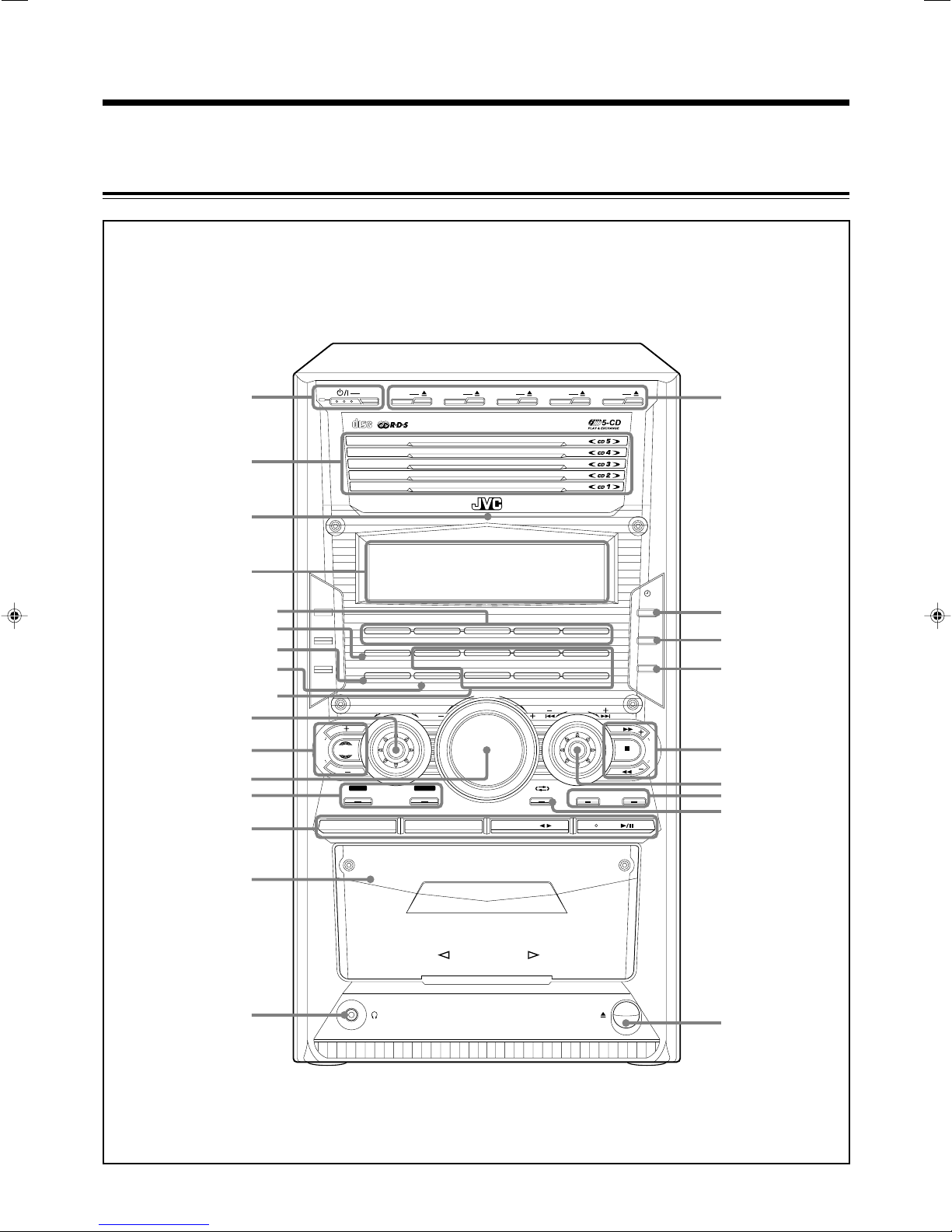
Become familiar with the buttons and controls on your unit.
Front Panel
Front Panel
*This illustration is for UK model.
3
Page 7
Continued
1
3
4
7
8
9
q
e
t
y
u
r
5
2
p
w
6
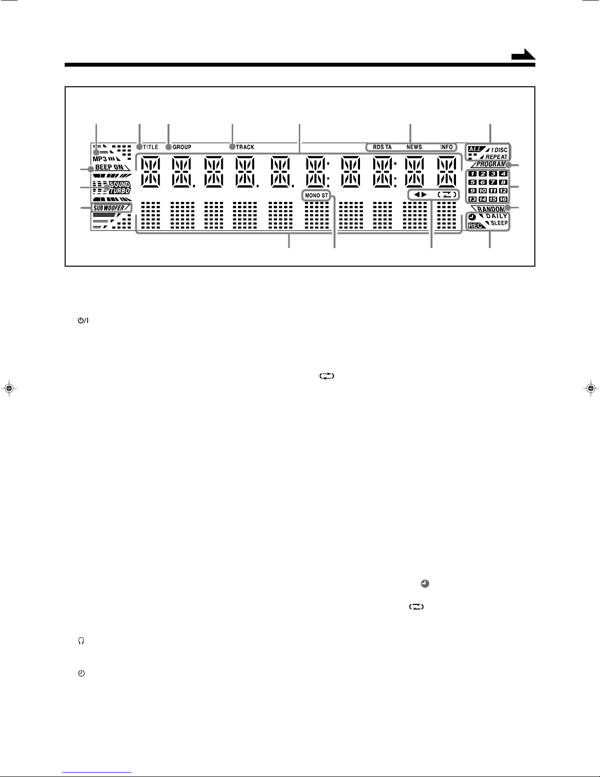
Display Window
See pages in parentheses for details.
Front Panel
1 (standby/on) button and STANDBY lamp (9, 27, 28)
ECO (Ecology) button (9)
2 Disc trays (CD1 – CD5)
3 Remote sensor
4 Display window
5 Indication lamp panel
1 CD ready lamps (16)
• CD1 READY, CD2 READY, CD3 READY,
CD4 READY, CD5 READY
2 SOUND TURBO lamp (11)
3 SUBWOOFER lamp (11)
4 REC lamp (24, 25)
5 Sound mode lamps (11)
• SOUND MODE
• Surround mode lamps
DANCE, HALL, STADIUM
• SEA (Sound Effect Amplifier) mode lamps
ROCK, POP, CLASSIC
6 SOUND MODE control (11)
7 SUBWOOFER LEVEL + / – buttons (11)
SOUND TURBO button (11)
8 VOLUME + / – control (10)
9 Recording buttons (24, 25, 28)
• REC START/STOP, CD REC START
p Source buttons (10)
Pressing one of these buttons also turns on the unit.
• AUX, FM/AM (13), TAPE 2 3 (23, 24),
CD 3/8 (19 – 21, 25)
q Cassette holder (23)
w PHONES jack (10)
e Disc number buttons (18, 20, 21, 25) and 0 (disc tray
r CLOCK/TIMER button (9, 26 – 29)
t SET/DISPLAY button (9, 12, 13, 20, 26 – 29)
y CANCEL/DEMO button (8, 9, 21, 26 – 29)
u TUNING + / – buttons (13)
open/close) buttons (18, 19, 22) (CD1 – CD5)
¡ / 1 (forward search/reverse search) buttons (12, 19, 23)
7 (stop) button
BEEP button (8, 12)
*This illustration is for UK model.
i PRESET + / – control (13)
¢ / 4 (forward skip/reverse skip) control
19
–
21, 25 – 28)
o Disc play mode buttons (20 – 22)
• CD PLAY MODE, REPEAT
; REVERSE MODE button (23 – 25)
a 0 EJECT button for cassette deck (23 – 25)
Display Window
1 MP3 indicator
2 TITLE indicator
3 GROUP indicator
4 TRACK indicator
5 Main display
• Shows the source name, frequency, etc.
6 Only for UK; RDS operation indicators (14, 15)
• RDS, TA, NEWS, INFO
7 REPEAT (ALL/1/DISC) indicators (22)
8 PROGRAM indicator (20)
9 Disc track number indicators
p RANDOM indicator (21)
q Timer indicators (26 – 29)
• DAILY (Daily Timer), SLEEP (Sleep Timer),
REC (Recording Timer), (Timer)
w Tape operation indicators (23 – 25)
• 2 3 (tape direction), (Reverse Mode)
e Tuner operation indicators (13)
• MONO, ST (stereo)
r Audio level indicator
t SUBWOOFER indicator (11)
y SOUND TURBO indicator (11)
u BEEP ON indicator (8, 12)
When one of the 6 preset sound modes is activated, this
will function as illumination display. For details, see
“Selecting the Sound Modes” on page 11.
(9, 12,
4
Page 8
Remote Control
PTY SELECT
PTY SELECT
TA/NEWS/INFO
DISPLAY MODE
PTY SEARCH
5
1
3
4
6
7
e
r
t
y
u
i
;
a
2
o
q
w
p
9
8
COMPACT
DIGITAL AUDIO
CD1
COMPACT COMPONENT SYSTEM
CD2 CD3 CD4 CD5
EXTENDED
SUPER BASS
CD-R/RW
PLAYBACK
CD1 READY
SOUND TURBO
SUBWOOFER
SOUND MODE D A N C E HALL
RE C ROCK CLASSICPOP
STADIUM
CD2 READY CD3 READY CD4 READY CD5 READY
CLOCK
/TIMER
SET
/
DISPLAY
CANCEL
/
DEMO
V
O
L
U
M
E
S
O
U
N
D
M
O
D
E
P
R
E
S
E
T
S
U
B
W
O
O
F
E
R
L
E
V
E
L
T
U
N
I
N
G
SOUND
TURBO
START/STOP
AUX TAPE CD
FM / AM
START REVERSE MODE CD PLAY MODE REPEAT
REC
CD REC
/BEEP
STANDBY
ECO
*This illustration is for UK model.
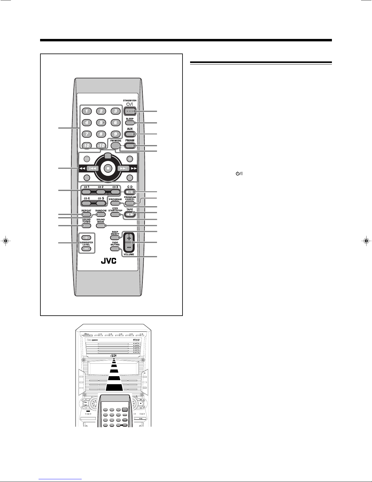
Remote Control
1 Number buttons (13, 19, 20)
2 ¢ (¡) (forward skip/forward search) button
(13, 19, 21, 23)
4 (1) (reverse skip/reverse search) button
(13, 19, 21, 23)
7 (stop) button
Only for UK; RDS operation buttons (14, 15)
• PTY SEARCH, PTY SELECT +, PTY SELECT −,
TA/NEWS/INFO, DISPLAY MODE
3 Disc number buttons (CD1 – CD5) (18, 20, 21)
Pressing one of these buttons also turns on the unit.
4 REPEAT button (22)
5 RANDOM button (21)
6 SOUND TURBO button (11)
7 SUBWOOFER LEVEL + / – buttons (11)
8 STANDBY/ON button (9)
9 SLEEP button (29)
p AUX button (10)
Pressing this button also turns on the unit.
q FM/AM button (10, 13)
Pressing this button also turns on the unit.
w FM MODE button (13)
e CD 3¥8 button (10, 19 – 21)
Pressing this button also turns on the unit.
r PROGRAM CANCEL button (21)
t PROGRAM button (20)
y TAPE 2 3 button (10, 23, 24)
Pressing this button also turns on the unit.
u REC START/STOP button (24)
i SOUND MODE button (11)
o BEEP ON/OFF button (8, 12)
; VOLUME + / – button (10)
a FADE MUTING button (10)
5
When using the remote control, point it
at the remote sensor on the front panel.
*This illustration is for UK model.
Page 9
Getting Started
ANTENNA
AM EXT
AM
LOOP
FM 75
COAXIAL
ANTENNA
AM EXT
AM
LOOP
FM 75
COAXIAL
Continued
Supplied Accessories
Make sure that you have all the following items.
The number in parentheses indicates the quantity of each
piece supplied.
• AM loop antenna (1)
• FM antenna (1)
• Remote control (1)
• Batteries (2)
If anything is missing, consult your dealer immediately.
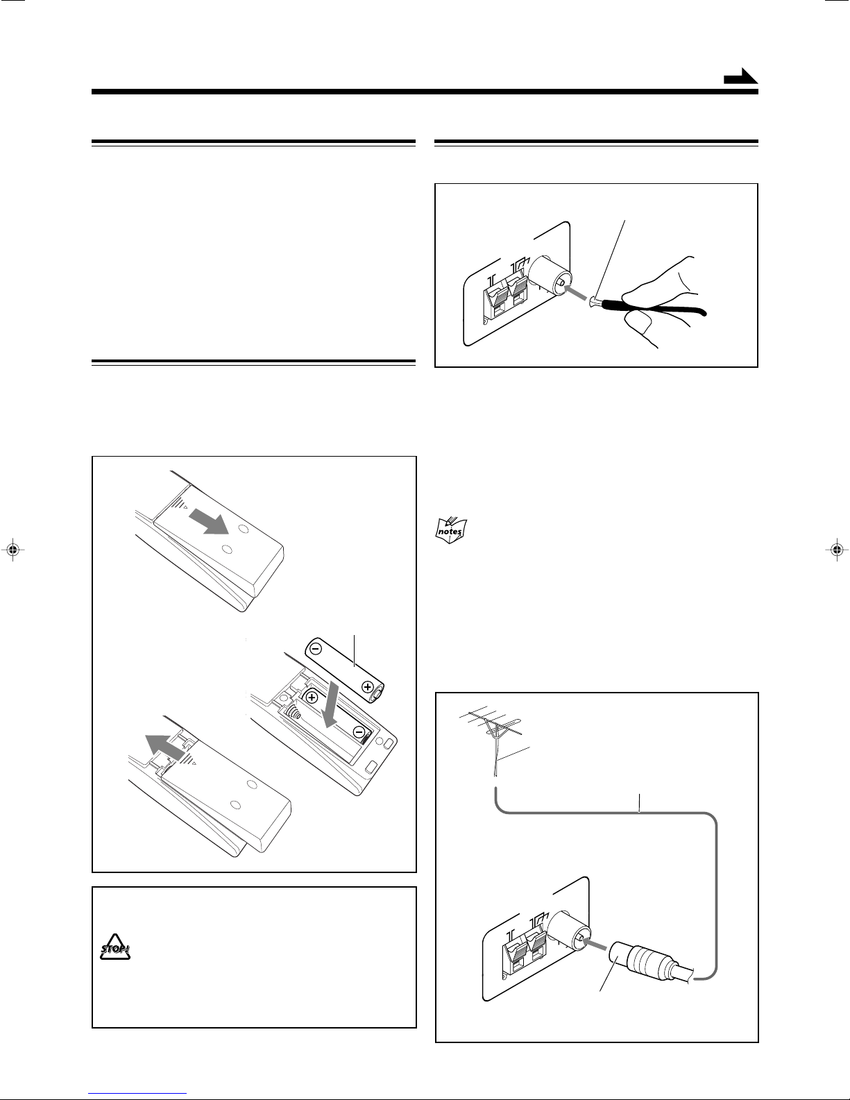
Putting the Batteries into the Remote Control
Insert the batteries—R6(SUM-3)/AA(15F)—into the remote
control, by matching the polarity (+ and –) on the batteries
with the + and – markings on the battery compartment.
When the remote control can no longer operate the unit,
replace both batteries at the same time.
1
Connecting Antennas
FM antenna
FM antenna (supplied)
1 Attach the FM antenna to the FM 75 Ω
COAXIAL terminal.
2 Extend the FM antenna.
3 Fasten it up in the position which gives you
the best reception, then fix it on the wall, etc.
2
3
• DO NOT use an old battery together with a new
one.
• DO NOT use different types of batteries together.
• DO NOT expose batteries to heat or flame.
• DO NOT leave the batteries in the battery
compartment when you are not going to use the
remote control for an extended period of time.
Otherwise, the remote control will be damaged
from battery leakage.
R6(SUM-3)/AA(15F)
About the supplied FM antenna
The FM antenna supplied with this unit can be used as temporary
measure. If reception is poor, you can connect an outdoor FM
antenna.
To connect an outdoor FM antenna
Before connecting the antenna, disconnect the supplied FM
antenna.
Outdoor FM antenna
(not supplied)
Coaxial cable (not supplied)
A 75 Ω antenna with coaxial type connector
(IEC or DIN 45325) should be used.
6
Page 10
AM antenna
ANTENNA
AM EXT
AM
LOOP
FM 75
COAXIAL
1
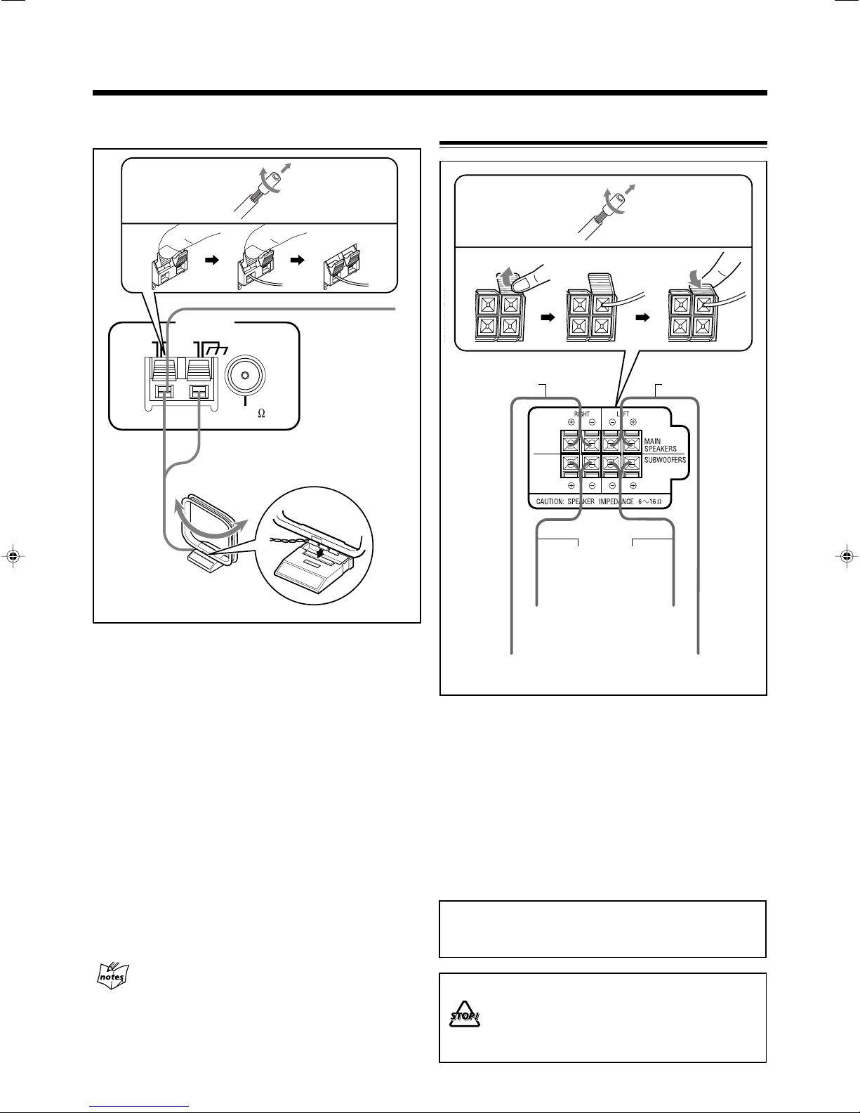
Connecting Speakers
1
2
3
4
Vinyl-covered wire
(not supplied)
5
AM loop antenna
(supplied)
1
If the cords are covered with insulation,
remove a short section of insulation at the
end of each cord by twisting and pulling it
off.
2 Press and hold the clamp of the AM LOOP
terminals on the rear of the unit.
3 Insert the AM loop antenna to the AM LOOP
terminals as illustrated.
4 Release your finger from the clamp.
5 Turn the AM loop antenna until you have the
best reception.
To connect an outdoor AM antenna
When reception is poor, connect a single vinyl-covered wire
to the AM EXT terminal and extend it horizontally. The AM
loop antenna must remain connected.
2
Speaker cords
(black/blue)
Speaker cords
(black/red)
From right
subwoofer
terminal
From right main
speaker terminal
3
Speaker cords
(black/blue)
From left
subwoofer
terminal
From left main
speaker terminal
1 If the cords are covered with insulation,
remove a short section of insulation at the
end of each cord by twisting and pulling it
off.
2 Insert the end of the speaker cord into the
terminal as illustrated.
Match the same polarity: (+) to (+) and (–) to (–).
3 Close the speaker terminals.
IMPORTANT: Use only speakers with the same speaker
impedance as indicated by the speaker terminals on the
rear of the unit.
For better reception of both FM and AM
• Make sure the antenna conductors do not touch any other terminals
and connecting cords.
• Keep the antennas away from metallic parts of the unit, connecting
cords, and the AC power cord.
7
• DO NOT connect more than one speaker to
each speaker terminal.
• DO NOT push or pull the speakers as this will
damage the foot spacers at the bottom of the
speakers.
Page 11
Connecting Other Equipment
BEEP
ON/OFF
FADE
MUTING
CANCEL
/
DEMO
T
U
N
I
N
G
/BEEP
Canceling the Demonstration
You can connect an external audio component used only as a
playback device.
• DO NOT connect any equipment while the power
is on.
• DO NOT plug in any equipment until all connections
are complete.
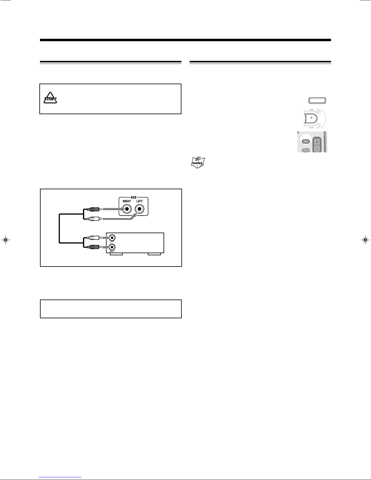
To connect an external audio component
Be sure that the plugs of the audio cords are colored: White
plugs and jacks are for left audio signals, and red ones for
right audio signals.
To play external audio component through this unit,
connect between the audio output jacks on the other
equipment and AUX jacks by using an audio cord (not
supplied).
Audio equipment
When connecting the AC power cord to a wall outlet, the unit
automatically starts demonstration.
To cancel the demonstration, press and hold
CANCEL/DEMO until “DEMO OFF” appears
on the display.
• To cancel only beep sounds during the
demonstration, press and hold BEEP for more
than 2 seconds or press BEEP ON/OFF on the
remote control.
The BEEP ON indicator goes off from the
display.
When you press other buttons
The demonstration stops temporarily. It will start automatically
again (if no operation is done for 2 minutes) unless you cancel it by
pressing CANCEL/DEMO.
To start demonstration manually
Press and hold CANCEL/DEMO again until “DEMO START”
appears on the display.
To audio output
Now, you can plug the AC power cord.
IMPORTANT: Be sure to check that all connections are
done before plugging the AC power cord into a wall outlet.
8
Page 12
Common Operations
ECO
STANDBY
ECO
STANDBY
ECO
STANDBY
SET
/
DISPLAY
P
R
E
S
E
T
T
U
N
I
N
G
CLOCK
/TIMER
SET
/
DISPLAY
P
R
E
S
E
T
T
U
N
I
N
G
CANCEL
/
DEMO
DAILY
Canceled
TIMER
(Daily Timer setting)
TIMER
(Recording Timer setting)
REC
Clock
setting
(The hour digits start flashing.)
Turning On or Off the Power
To turn on the unit, press (or
STANDBY/ON on the remote
control) so that the STANDBY lamp
goes off.
To turn off the unit (standby), press
(or STANDBY/ON on the
remote control) again so that the
STANDBY lamp lights up.
• A little power is always consumed even while the unit is on
standby.
To switch off the power supply completely, unplug the AC
power cord from the AC outlet.
When you unplug the AC power cord or if a power
failure occurs
The clock is reset to “0:00” immediately, while the tuner preset
stations (see page 13) will be erased in a few days.
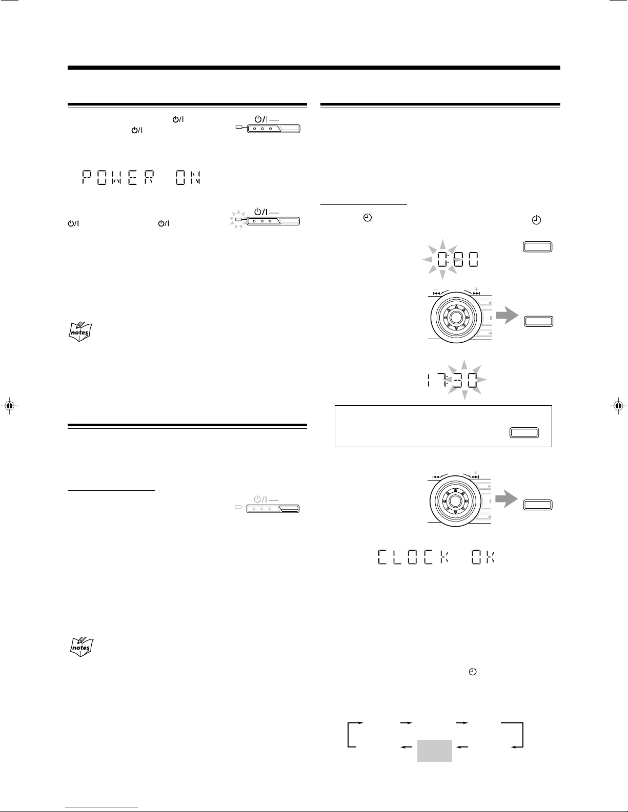
Setting the Clock
Before operating the unit any further, first set the clock built
in this unit. “0:00” will flash on the display until you set the
clock.
• You can set the clock whether the unit is on or off.
• If Ecology Mode is activated, you cannot set the clock
while the unit is off.
On the unit ONLY:
1
Press CLOCK/TIMER.
The hour digits start flashing on the display.
2
Turn ¢ / 4
to adjust the
hour, then press
SET/DISPLAY.
The minute digits start
flashing on the display.
Saving the Power Consumption while on Standby
(Ecology Mode)
You can save the power consumption while the unit is turned
off (on standby).
• You can set Ecology Mode whether the unit is on or off.
On the unit ONLY:
To activate the Ecology Mode, press
ECO.
“ECO” appears on the display for 2 seconds (and
demonstration is canceled temporarily if you have pressed the
button while the unit is off).
• Each time you press the button, “ECO” and “NORMAL”
appear alternately on the display.
To deactivate the Ecology Mode, press ECO again.
“NORMAL” appears (and demonstration starts if the unit is
turned off).
When you turn off the unit with Ecology Mode activated
“ECO” flashes on the display, and the clock time will not be shown
while the unit is turned off.
To correct the hour after pressing
SET/DISPLAY, press CANCEL/DEMO.
The hour digits start flashing again.
3
Turn ¢ / 4
to adjust the
minutes, then
press
SET/DISPLAY.
To check the clock time while playing a source
Press and hold SET/DISPLAY.
•
Each time you press and hold the button, the source indication
and the clock time alternate on the display.
To adjust the clock again
If you have set the clock before, press CLOCK/TIMER
repeatedly until the clock setting mode is selected.
• Each time you press the button, the clock/timer setting
modes change as follows:
9
Page 13
Adjusting the Volume
AUX TAPE CD
FM / AM
V
O
L
U
M
E
BEEP
ON/OFF
FADE
MUTING
VOLUME
BEEP
ON/OFF
FADE
MUTING
VOLUME
Continued
• When you unplug the AC power cord or if a power failure
occurs
The clock loses its setting and is reset to “0:00.” If this happens,
set the clock again.
• The clock may gain or loss 1 to 2 minutes per month
If this happens, reset the clock.
Selecting the Sources
Press one of the source buttons—FM/AM, CD 3¥8,
TAPE 2 3, and AUX.
When you press one of the source buttons (FM/AM,
CD 3/8, TAPE 2 3, and AUX), the unit turns on and starts
playing the source if it is ready.
• To listen to the FM/AM broadcasts, press FM/AM.
(See page 13.)
• To play back discs, press CD 3¥8. (See pages 16 – 22.)
• To play back tapes, press TAPE 2 3. (See page 23.)
•
To select an external component as the source, press AUX.
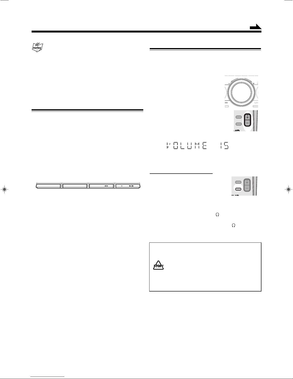
You can adjust the volume level only while the unit is turned
on. The volume level can be adjusted in 32 steps (VOLUME
MIN, VOLUME 1 – VOLUME 30, and VOLUME MAX).
The volume level control does not affect recording.
Turn VOLUME + / – clockwise (+)
to increase the volume or
counterclockwise (–) to decrease it.
When using the remote control, press
VOLUME + to increase the volume or
VOLUME – to decrease it.
• When adjusting the volume, the back color
on the display changes as increasing/
decreasing the level—not lighting ↔ blue
↔ purple ↔ pink ↔ red.
To turn off the volume level temporarily
On the remote control ONLY:
Press FADE MUTING.
The volume level gradually decreases to
“VOLUME MIN.”
To restore the sound, press the button again.
To listen with headphones
Connect a pair of headphones to the PHONES jack on the
unit. The sound will no longer come out of the speakers.
Disconnecting a pair of headphones from the PHONES
jack activates the speakers again.
• DO NOT set the volume to a high level before
connecting or putting on headphones.
•
DO NOT turn off (standby) the unit with the volume
set to an extremely high level; otherwise, a sudden
blast of sound can damage your hearing, speakers
and/or headphones when you turn on the unit or
start playing any source next time.
REMEMBER, you cannot adjust the volume level
while the unit is off (standby).
10
Page 14
Reinforcing the Bass Sound
RANDOM
REPEAT
SOUND
TURBO
SOUND
MODE
STA
S
O
U
N
D
M
O
D
E
S
U
B
W
O
O
F
E
R
L
E
V
E
L
SOUND
TURBO
DANCE
OFF
(Canceled)
HALL STADIUM
ROCK
POP
CLASSICUSER 1USER 2
USER 3
SOUND TURBO
SUBWOOFER
SOUND MODE D A N C E HALL
REC ROCK CLASSICPOP
STADIUM
S
U
B
W
O
O
F
E
R
L
E
V
E
L
SOUND
TURBO
Selecting the Sound Modes
Changing the subwoofer level
You can select one of the 3 subwoofer levels—LEVEL 0
(MIN LEVEL), LEVEL 1, and LEVEL 2 (MAX LEVEL).
This function only affects the playback sound, but does not
affect your recording.
Press SUBWOOFER LEVEL + to increase
the subwoofer level or SUBWOOFER
LEVEL – to decrease it.
The SUBWOOFER indicator lights up on the
display.
The SUBWOOFER lamp also flashes when LEVEL 1 or LEVEL 2
(MAX LEVEL) is selected. The lamp stops flashing when LEVEL 0
(MIN LEVEL) is selected.
To enjoy heavy sound
You can enjoy heavy sound by using Sound Turbo. This
function boosts the low and high frequency sound.
• Activating Sound Turbo cancels the sound mode and/or
subwoofer adjustment.
Press SOUND TURBO.
The SOUND TURBO indicator lights up on the
display and the SOUND TURBO lamp also flashes.
The subwoofer level increases to the maximum
level (LEVEL 2).
• Each time you press SOUND TURBO, Sound Turbo is turned on
(subwoofer LEVEL 2) or off (subwoofer LEVEL 0).
You can select one of the 6 preset sound modes (3 surround
modes and 3 SEA—Sound Effect Amplifier—modes) and 3
user modes. This function only affects the playback sound,
but does not affect recording.
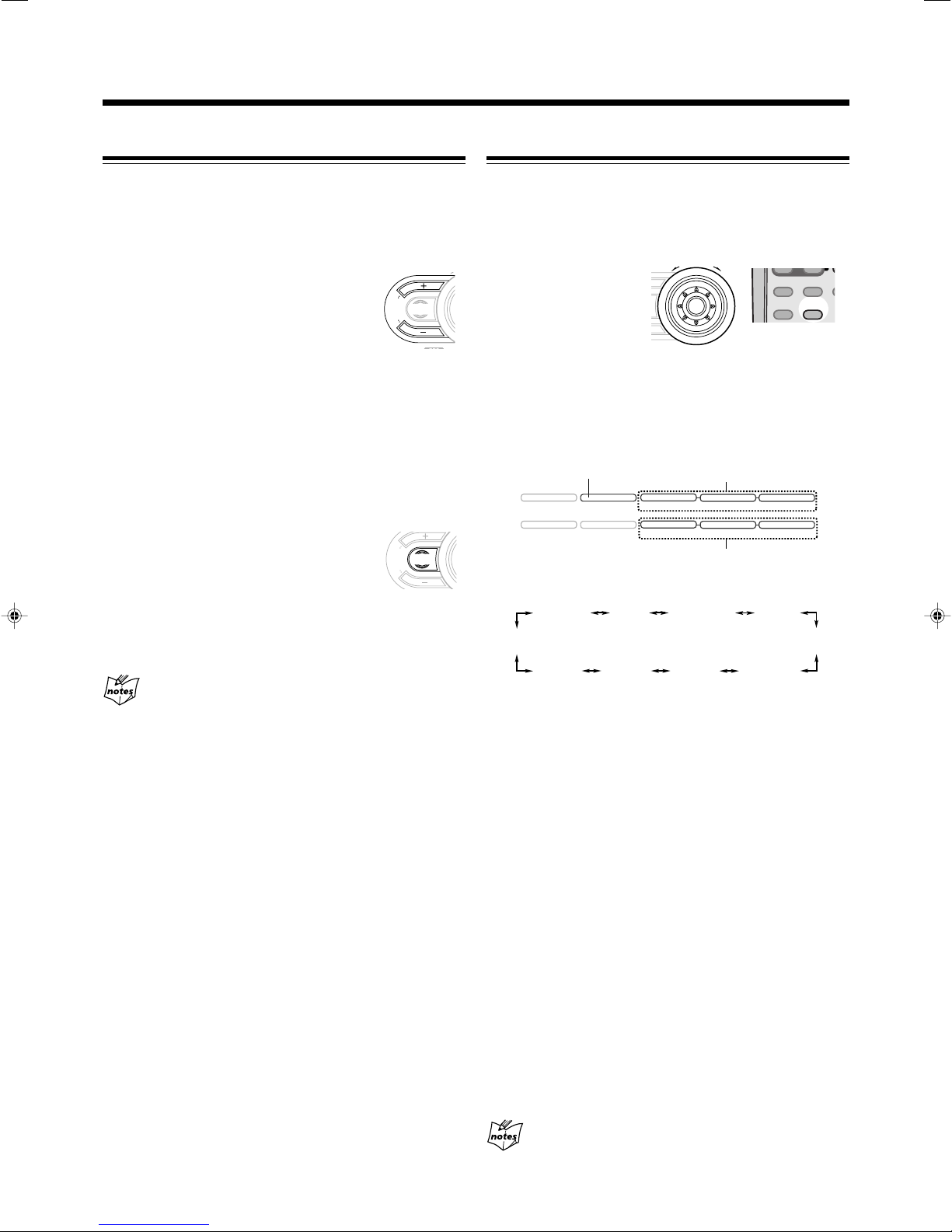
To select the sound
modes, turn SOUND
MODE (or press SOUND
MODE on the remote
control) until the sound
mode you want appears on
the display.
• When one of the sound modes is selected, the lamp for the
selected sound mode and the SOUND MODE lamp flash.
• When one of the user modes (USER 1, USER 2, or USER 3) is
selected, only the SOUND MODE lamp flashes.
SOUND MODE lamp
Surround mode lamps
SEA mode lamps
The sound modes change as follows:
If you press SUBWOOFER + / – or select a sound mode
during activating Sound Turbo
Sound Turbo is canceled.
When using the remote control, the sound mode changes only
clockwise in the above sequence.
Surround modes*
DANCE: Increases resonance and bass.
HALL: Adds depth and brilliance to the sound.
STADIUM: Adds clarity and spreads the sound, as in an
outdoor stadium.
SEA (Sound Effect Amplifier) modes
ROCK: Boosts low and high frequency. Good for acoustic
music.
POP: Good for vocal music.
CLASSIC: Good for classical music.
User modes
USER 1/2/3: Your individual mode stored in memory. See
“Creating Your Own Sound Mode—User
Mode” on page 12.
OFF: The sound mode is canceled.
* Surround elements are added to the SEA elements to create a
being-there feeling in your room.
11
When you turn on Sound Turbo
The sound mode is canceled.
Page 15

Creating Your Own Sound Mode—User Mode
SET
/
DISPLAY
P
R
E
S
E
T
T
U
N
I
N
G
/BEEP
SET
/
DISPLAY
P
R
E
S
E
T
T
U
N
I
N
G
BEEP
ON/OFF
FADE
MUTING
VOLUME
T
U
N
I
N
G
/BEEP
You can change the SEA pattern to suit your preference. The
SEA pattern can be adjusted using 3 frequency ranges—BASS,
MID (middle), and TRE (treble). These changed settings can
be stored as the USER 1, USER 2, and USER 3 modes.
• There is a time limit in doing the following steps. If the setting
is canceled before you finish, start from step 1 again.
On the unit ONLY:
1
Select one of the preset sound modes.
• If you want to add surround elements into your SEA
pattern, select one of the surround modes (DANCE,
HALL, or STADIUM) before starting the procedure
below. (See “Selecting the Sound Modes” on page 11.)
To use your own sound mode
Select USER 1, USER 2, or USER 3 mode when using the
sound modes. See “Selecting the Sound Modes” on page 11.
When you unplug the AC power cord or if a power
failure occurs
The setting will be erased in a few days. If this happens, set the user
modes again.
Turning On or Off the Key-touch Tone
If you do not want the key-touch tone to beep each time you
press a button or turn a control, you can deactivate it.
The BEEP ON indicator goes off from the display.
2
Press SET/DISPLAY while the
selected sound mode is still shown
on the display.
Current level appears.
3
Adjust the SEA pattern.
1) Turn ¢ / 4 to select the
frequency range (BASS,
MID or TRE).
2) Press ¡ or 1 to adjust
the level (–3 to +3) of the
selected frequency range.
3) Repeat steps 1) and 2) to adjust the level of the other
frequency ranges.
4
Press SET/DISPLAY again.
On the unit:
Press and hold BEEP for more
than 2 seconds.
On the remote control:
Press BEEP ON/OFF.
• Each time you press the button, the keytouch tone turns on and off alternately.
5
Tu rn ¢ / 4 to select one
of the user modes (USER 1,
USER 2, or USER 3) in which
you want to store your SEA
pattern.
6
Press SET/DISPLAY again.
The SEA pattern you have created is stored into the user
mode selected in step 5.
12
Page 16

Listening to FM and AM Broadcasts
FM / AM
T
U
N
I
N
G
/BEEP
AUX
FM/AM
FM MODE
SET
/
DISPLAY
P
R
E
S
E
T
T
U
N
I
N
G
P
R
E
S
E
T
T
U
N
I
N
G
FM / AM
FM MODE
Tuning in to a Station
1
Press FM/AM.
The unit automatically turns on and
tunes in to the previously received
station (either FM or AM).
• Each time you press the button, the band alternates
between FM and AM.
2
Start searching for stations.
On the unit:
Press and hold TUNING +
or TUNING – for more than 1
second.
On the remote control:
Press and hold ¢ (¡)
or 4 (1) for more
than 1 second.
The unit starts searching for
stations and stops when a station of sufficient signal
strength is tuned in.
• If a program is broadcast in stereo, the ST (stereo)
indicator lights up.
To stop searching, press TUNING + or TUNING – (or
¢ (¡) / 4 (1) on the remote control).
When you press TUNING + or TUNING – (or ¢ (¡) /
4 (1) on the remote control) briefly and repeatedly
The frequency changes step by step.
On the unit ONLY:
1
Tune in to the station you want to preset.
• See “Tuning in to a Station.”
2
Press SET/DISPLAY.
3
Turn PRESET + / – to select a
preset number.
4
Press SET/DISPLAY again.
The tuned station in step 1 is stored in the preset number
selected in step 3.
• Storing a new station on a number already used erases
the previously stored one.
When you unplug the AC power cord or if a power
failure occurs
The preset stations will be erased in a few days. If this happens,
preset the stations again.
To change the FM reception mode
On the remote control ONLY:
When an FM stereo broadcast is hard to
receive or noisy, press FM MODE so that
the MONO indicator lights up on the
display. Reception will improve.
To restore the stereo effect, press FM MODE again so that
the MONO indicator goes off. In this stereo mode, you can
hear stereo sounds when a program is broadcasted.
Presetting Stations
You can preset 30 FM and 15 AM stations.
In some cases, test frequencies have been already memorized
for the tuner since the factory examined the tuner preset
function before shipment. This is not a malfunction. You can
preset the stations you want into memory by following the
presetting method.
• There is a time limit in doing the following steps. If the setting
is canceled before you finish, start from step 2 again.
13
Tuning in to a Preset Station
1
Press FM/AM.
The unit automatically turns on and
tunes in to the previously received
station (either FM or AM).
• Each time you press the button, the band
alternates between FM and AM.
2
Select a preset number.
On the unit:
Turn PRESET + / –.
On the remote control:
Press the number buttons.
Ex.: For preset number 5, press 5.
For preset number 15, press
+10, then 5.
For preset number 25, press
+10, +10, then 5.
For preset number 30, press
+10, +10, then 10.
Page 17

Receiving FM Stations with RDS—Only for UK
PS
(Program Service)
PTY
(Program Type)RT(Radio Text)
Station frequency
(or preset channel no.)
DISPLAY MODE
PTY SELECT
PTY SELECT
TA/NEWS/INFO
DISPLAY MODE
PTY SEARCH
PTY SEARCH
Continued
RDS (Radio Data System) allows FM stations to send an
additional signal along with their regular program signals.
For example, the stations send their station names, as well as
information about what type of program they broadcast, such
as sports or music, etc.
When tuning in to an FM station which provides the RDS
service, the RDS indicator lights up on the display.
With the unit, you can receive the following types of RDS
signals.
PS (Program Service):
Shows commonly known station names.
PTY (Program Type):
Shows types of broadcast programs.
RT (Radio Text):
Shows text messages the station sends.
Enhanced Other Networks:
Provides the information about the types of the programs
sent by other RDS stations.
More about RDS
• Some FM stations do not provide RDS signals.
• RDS services vary among FM RDS stations. For details on RDS
services in your area, check with local radio stations.
• RDS may not work correctly if the received station is not
transmitting the signals properly or if the signal strength is weak.
Searching for Programs by PTY Codes
(PTY Search)
One of the advantages of RDS is that you can locate a
particular kind of program by specifying the PTY codes.
• For details on the PTY codes, see “Additional Information”
on page 30.
To search for a program using the PTY codes
REMEMBER you must preset FM RDS stations to use the
PTY codes. If not yet done, see page 13.
• There is a time limit in doing the following steps. If the setting
is canceled before you finish, start from step 1 again.
On the remote control ONLY:
1
Press PTY SEARCH.
“PTY SELECT” appears on
the display.
2
Press PTY SELECT +
or PTY SELECT –
until the PTY code you
want appears on the
display.
• Each time you press the button, the PTY codes change
as follows:
Changing the RDS Information
You can see RDS information on the display while listening
to an FM station.
On the remote control ONLY:
Press DISPLAY MODE.
• Each time you press the button, the display
changes to show the following information:
• If no PS, PTY, or RT signals are sent by a station
“NO PS,” “NO PTY,” or “NO RT” appears on the display.
• If the unit takes time to show the RDS information received
from a station
“WAIT PS,” “WAIT PTY,” or “WAIT RT” may appears on the
display.
NEWS “ AFFAIRS “ INFO “ SPORT “
EDUCATE “ DRAMA “ CULTURE “
SCIENCE “ VARIED “ POP M “ ROCK M “
EASY M “ LIGHT M “ CLASSICS “
OTHER M “ WEATHER “ FINANCE “
CHILDREN “ SOCIAL “ RELIGION “
PHONE IN “ TRAVEL “ LEISURE “ JAZZ “
COUNTRY “ NATION M “ OLDIES “
FOLK M “ DOCUMENT “ TEST “ ALARM “
(back to the beginning)
3
Press PTY SEARCH once again.
While searching, “SEARCH” and the
selected PTY code appear on the display
alternately.
The unit searches 30 preset FM stations, stops when it
finds the one you have selected (“FOUND” appears), and
tunes in to that station.
• If no program is found, “NOT FOUND” appears on the
display and the unit returns to the last received station.
To stop searching any time during the process, press
PTY SEARCH while searching.
14
Page 18

Switching to a Program Type of Your Choice
TA
NEWS INFO
OFF
(Canceled)
TA/NEWS/INFO
Temporarily
How the Enhanced Other Networks function actually
works:
The Enhanced Other Networks function allows the unit to
switch temporarily to a broadcast program of your choice
(TA, NEWS, or INFO) from a different station.
• The Enhanced Other Networks function only works when
you are listening to a preset FM RDS stations providing the
data.
To activate the Enhanced Other Networks function
REMEMBER you must preset FM RDS stations to use the
function. If not yet done, see page 13.
• There is a time limit in doing the following steps. If the setting
is canceled before you finish, start from step 1 again.
On the remote control ONLY:
1
Press TA/NEWS/INFO until the
data type you want appears on
the display.
The selected data type indicator flashes on
the display.
• Each time you press the button, the data types change as
follows:
CASE 1
If there is no station broadcasting the program you
have selected
The unit continues tuning in to the current station.
«
When a station starts broadcasting the program you have
selected, the unit automatically switches to the station.
The indicator of received PTY code starts flashing.
«
When the program is over, the unit goes back to the
previously tuned station, but the function still remains
activated.
CASE 2
If there is a station broadcasting the program you
have selected
The unit tunes in to the program. The indicator of received
PTY code starts flashing.
«
When the program is over, the unit goes back to the
previously tuned station, but the function still remains
activated.
CASE 3
TA: Traffic announcement
NEWS:News
INFO: Program the purpose of which is to impart
advice in the widest sense.
OFF: The function is canceled. The data type indicator
(TA, NEWS, INFO) goes off.
2
Wait for about 5 seconds after specifying the
data type.
The data type indicator stops flashing and remains lit.
Now, the function is activated. See “How the Enhanced
Other Networks function actually works.”
If the FM station you are listening to is broadcasting
the program you have selected
The unit continues to receive the station but the indicator
of received PTY code starts flashing.
«
When the program is over, the indicator of received PTY
code stops flashing and remains lit, but the function still
remains activated.
More about the Enhanced Other Networks function
• The data sent from some stations may not be compatible with this
unit. In this case, the function may not work correctly.
• While listening to a program tuned in by the function, the station
does not change even if another network station starts
broadcasting a program of the same data.
• The function is canceled when you change the source to CD,
TAPE, or AUX, while it is temporarily canceled when you change
the source to AM.
• This function is also canceled when you turn off the unit.
15
Page 19

Disc Play Introduction
CD1 READY
CD2 READY CD3 READY CD4 READY C D5 READY
Continued
This unit has been designed to play back the following discs:
• CD (Audio CD)/CD-R (CD-Recordable)/CD-RW (CDReWritable)
• MP3 disc (MP3 files recorded on a CD-R or CD-RW)*
When playing a CD-R or CD-RW
User-edited CD-Rs (CD-Recordable) and CD-RWs
(CD-ReWritable) can be played back only if they have been
“finalized.”
• You can play back your original CD-Rs or CD-RWs recorded
in music CD format or in MP3 format. However, they may
not be played back depending on their characteristics or
recording conditions.
• Before playing back CD-Rs or CD-RWs, read their
instructions or cautions carefully.
• Some CD-Rs or CD-RWs may not play back on this unit
because of their disc characteristics, damage or stain on
them, or if the player’s lens is dirty.
• CD-RWs may require a longer readout time. This is caused
by the fact that the reflectance of CD-RWs is lower than for
regular discs.
About the CD ready lamps
Each CD ready lamp shows the status of a disc placed on
each corresponding disc tray (CD1 – CD5).
• CD ready lamps light up
When the disc is loaded and currently selected.
• CD ready lamps light slightly
When the disc is loaded, but not currently selected.
• CD ready lamp flashes
When the disc is played back or paused.
• CD ready lamps goes off
When the unit detects there is no disc loaded on a
certain tray. (“NO DISC # (number)” appears on the
display.)
*About MP3
MP3 is an abbreviation of Motion Picture Experts Group 1
(or MPEG-1) Audio Layer 3. MP3 is simply a file format
with a data compression ratio of 1:10 (128 kbps*). By using
MP3 format, one CD-R or CD-RW can contains 10 times as
much data volume as a regular CD can.
* Bit rate is the average number of bits that one second of audio
data will consume. The basic unit of measurement for bitrate is
kbps (1,024 bits per second). To get a better audio quality, choose
a higher bit rate. The most popular bit rate for encoding
(recording) is 128 kbps.
MP3 disc structure
On an MP3 disc, each song (material) is recorded as a file.
Files are grouped into a folder. Folders can also include other
folders, creating hierarchical directory layers. (See “How are
MP3 files recorded and played back?” on page 17.)
This unit manages files and folders as “tracks” and “groups.”
This unit can recognize up to 255 groups per disc (up to 999
tracks). The unit ignores those exceeding the maximum
numbers and cannot play them back.
More about MP3 discs
• MP3 discs (either CD-R or CD-RW) require a longer readout time.
(It varies due to the complexity of the recording configuration.)
• When making an MP3 disc, select ISO 9660 Level 1 or Level 2 as
the disc format.
• This unit does not support multisession recording.
• This unit can play MP3 files only with the following file extensions—
“.MP3,” “.Mp3,” “.mP3,” and “.mp3.”
• Files other than MP3 are ignored.
• Some MP3 discs may not be played back because of their disc
characteristics or recording conditions.
If the loaded disc is an MP3 disc
The corresponding CD ready lamp and the MP3 indicator will
light up.
16
Page 20

How are MP3 files recorded and played back?
1 (Root)
2
(3)*
5
6
7
8
9
10
(11)*
12
(4)*
MP3 “tracks (files)” can be recorded in “group”—folders in
PC terminology.
During recording, the tracks and groups can be arranged
similarly to the tracks and folders of computer data. “Root” is
similar to the root of a tree. Every track and group can be
linked to the root.
In compliance with ISO 9660, the maximum allowable depth
of nested folders—so called “hierarchy”—is eight (inclusive
of the root).
Playback order, track search order, and group search order of
the MP3 tracks recorded on a disc are determined by the
writing (or encoding) application; therefore, playback order
may be different from the one you have intended while
recording the groups and the tracks.
The illustration shows an example of how MP3 tracks are
recorded on a CD-R or CD-RW, how they are played back
and how they are searched for on this unit.
• The numbers in circles next to the MP3 tracks (
the playback order and search order of the MP3 tracks.
Normally this unit plays back MP3 tracks in the recorded
order.
• The numbers inside the groups indicate the playback order
and search order of the groups on an MP3 disc. Normally
this unit plays back MP3 tracks in the groups in the
recorded order.
The groups marked with asterisk (*) will be skipped since
they do not include any MP3 tracks.
) indicate
MP3 group/track configuration:
17
Page 21

CD1 CD2 CD3 CD4 CD5
CD1 CD2 CD3 CD4 CD5
Playing Back Discs
CD1 CD2 CD3 CD4 CD5
Continued
Loading Discs
On the unit ONLY:
1
Press 0 for the disc tray (CD1 – CD5) you
want to load a disc onto.
The unit automatically turns on and the disc tray comes
out.
2
Place a disc correctly on the circle of the disc
tray, with its label side up.
CORRECT
• When using a CD single (8 cm), place it on the inner
circle of the disc tray.
3
Press the same 0 you have pressed in step 1.
The disc tray closes.
INCORRECT
Playing Back the Entire Discs—Continuous Play
You can play discs continuously.
• If you start Continuous Play with an MP3 disc, you can
select a track to start playback.
7 For audio CDs
1
Load discs.
2
Press one of the corresponding disc number
buttons (CD1 – CD5) for the disc you want to
play.
The unit searches for the disc, and starts playing with the
first track of the selected disc.
Track number
Tracks of the currently playing CD (Track
numbers exceeding 16 are not displayed.)
Elapsed playing time
7 For MP3 discs
When loading more than one disc
When you press 0 for the next tray you want to place another disc
onto, the first disc tray automatically closes and then the next tray
comes out.
1
Load discs.
2
Press one of the corresponding disc number
buttons (CD1 – CD5) you load discs in step 1.
The unit searches for the disc (it may take time), and
starts playing the first track of the disc.
• The MP3 indicator lights up on the display.
3
Press 7.
The group title of the 1st group appears on the display,
then the group number starts flashing.
Group title of the 1st group*
Group number flashes
* If the entire group title cannot be shown (exceeds
10 characters), the title scrolls.
18
Page 22

P
R
E
S
E
T
T
U
N
I
N
G
CD
CD
P
R
E
S
E
T
T
U
N
I
N
G
T
U
N
I
N
G
/BEEP
4
CD1 CD2 CD3 CD4 CD5
FM MODE
Select a group and track to start playing.
1) Turn ¢ / 4 (or press ¢ (¡)
/ 4 (1) on the remote control)
to select a group you want, then
press CD 3¥8.
The track number starts flashing.
Track number flashes
2) Turn ¢ / 4 (or press ¢ (¡) / 4 (1) on
the remote control) to select a track you want to start
playback with, then press CD 3¥8.
Basic Disc Operations
While playing a disc, you can do the following operations.
To exchange discs during playback of another disc
Press 0 corresponding to a disc (CD1 – CD5), not playing or
selected currently, to eject and exchange the disc.
If you exchange discs during play, the current play will not
stop until all discs you have exchanged are played.
To stop play for a moment
Press CD 3¥8.
While pausing, the elapsed playing time
flashes on the display.
To resume playing, press CD 3¥8 again.
Track title**
Group number
Elapsed playing time
Track number
** If the entire track title cannot be shown (exceeds
10 characters), the title scrolls.
Playback starts with the selected track of the selected group.
To stop playing, press 7.
To remove the disc, press 0 for the corresponding disc tray.
Disc playback sequence
When discs* in more than one tray are loaded on the disc
trays, they are played in sequence as follows:
Ex.: When CD2 is pressed:
CD2 ] CD3 ] CD4 ] CD5 ] CD1 (then stops)
* When no disc is loaded on the tray, that disc number is
skipped.
19
To go to another track
For audio CDs: Before or during play
For MP3 discs: During play
Turn ¢ / 4 (or press ¢ (¡) /
4 (1) on the remote control).
• ¢ (or ¢ (¡)):
Skips to the beginning of the next
or succeeding tracks.
• 4 (or 4 (1)):
Goes back to the beginning of the current or previous
tracks.
To locate a particular point in a track
During play, press and hold ¡ or
1 (or ¢ (¡) / 4 (1) on
the remote control).
• ¡ (or ¢ (¡)): Fast-forwards the
disc.
• 1 (or 4 (1)): Fast-reverses the disc.
To go to another track directly using the number
buttons
On the remote control ONLY:
Pressing the number button(s) before or
during play allows you to start playing the
track number you want.
Ex.: For track number 5, press 5.
For track number 15, press +10,
then 5.
For track number 20, press +10,
then 10.
For track number 32, press +10
three times, then 2.
For track number 132, press +10
thirteen times, then 2.
Page 23

T
U
N
I
N
G
Continued
Programming the Playing Order of the Tracks
—Program Play
You can arrange the playing order of the tracks before you
start playing. You can program up to 100 tracks.
• To use Repeat Play (see page 22) for Program Play, press
REPEAT after starting Program Play. Only REPEAT 1 and
REPEAT ALL can be selected for Program Play.
• There is a time limit in doing the following steps. If the setting
is canceled before you finish, start from step 2 again.
1
Load discs.
• If the current playing source is not the CD player, press
CD 3¥8, then 7 before going to the next step.
2
Activate Program Play.
On the unit:
5
OM
PROGRAM
START/STOP
CD PLAY MODE
PROGRAM
CANCEL
REC
TAPE
Press CD PLAY MODE repeatedly
until “CD PROGRAM” appears
on the display.
• Each time you press the button, the play
mode changes as follows:
CD PROGRAM
Total track number and
total playing time (Continuous Play)
CD RANDOM
On the remote control:
Press PROGRAM so that
“CD PROGRAM” appears
on the display.
The PROGRAM indicator lights up on the display.
4
Select a track from the selected disc in step 3.
• Program step numbers exceeding 100 cannot be
programed.
• When making programs from MP3 discs, the unit only
recognizes tracks like audio CD. You cannot make
programs using group numbers.
On the unit:
Turn ¢ / 4
S
E
E
R
T
P
to select the
track number,
then press
SET/DISPLAY.
On the remote control:
Press the number buttons.
• For how to use the number buttons,
see “To go to another track directly
using the number buttons” on page
19.
5
Program other tracks you want.
• To program tracks from the same disc, repeat step 4.
• To program tracks from a different disc, repeat steps
and 4.
6
Press CD 3¥8.
The tracks are played in the order you
have programed.
• If the playing disc is an MP3 disc, the MP3 indicator
lights up.
SET
DISPLAY
/
FM MODE
CD
3
• If a program has been stored in memory, the program is
called up.
3
Press one of the disc number buttons (CD1 –
CD5) to select the disc you want.
CD1 CD2 CD3 CD4 CD5
Track number
Disc number
Program step number
To stop playing, press 7.
To exit from Program Play, press CD PLAY MODE
repeatedly until the PROGRAM indicator goes off (or press
PROGRAM on the remote control) after playback stops.
• If you try to program a 101st track, “CD FULL” appears on the
display.
• If you have tried to program a track from an empty tray, “NO
READ # (number)” or “NO DISC # (number)” will appear on the
display for 2 seconds.
• If you have tried to program a track number that does not
exist, it is ignored.
• If you try to open a disc tray during Program Play, the disc
tray does not come out. Open disc trays after canceling Program
Play.
• When “NO READ” appears on the display
You are selecting the disc that the unit has not read yet.
20
Page 24

CD PROGRAM
Total track number and
total playing time (Continuous Play)
CD RANDOM
CD1 CD2 CD3 CD4 CD5
T
U
N
I
N
G
/BEEP
CD PLAY MODE
RANDOM
PRO
REPEAT
SOUND
TURBO
SOUND
MODE
R
STAR
CD
4
CD 5
CD
To check the program contents
PROGRAM
PROGRAM
CANCEL
TAPE
REC
START/STOP
CD
3
CD
CANCEL
/
DEMO
On the remote control ONLY:
Before playing, you can check the
program contents by pressing
¢ (¡) or 4 (1).
• ¢ (¡) : Shows them in the
programed order.
• 4 (1) : Shows the programed tracks in the reverse
order.
To modify the program
To erase the last programed tracks, press
CANCEL/DEMO (or press PROGRAM
CANCEL on the remote control).
• Each time you press the button, the last
programed track is erased from the
program.
To add tracks into the program before playing, simply
select the track numbers you want to add by following step
of the programming procedure. If you want to add tracks
from another disc, follow steps 3 and 4.
To erase the entire program before or after playing, press
7 until “CD PROGRAM” appears on the display.
• The program you have made will be erased:
– when you unplug the AC power cord, or
– when a power failure occurs.
Playing at Random—Random Play
The tracks of all the loaded discs will be played at random.
• To use Repeat Play (see page 22) for Random Play, press
REPEAT after starting Random Play. Only REPEAT 1 and
REPEAT ALL can be selected for Random Play.
1
Load a disc.
2
Press the corresponding disc number button
(CD1 – CD5) where a disc is loaded in step 1,
then press 7.
3
Activate Random Play.
On the unit:
4
Press CD PLAY MODE repeatedly
until “CD RANDOM” appears on
the display.
• Each time you press the button, the play mode changes
as follows:
21
On the remote control:
Press RANDOM so that “CD
RANDOM” appears on the
display.
• The RANDOM indicator also lights up on the display.
4
Press CD 3¥8.
The tracks are played randomly.
Random Play ends when all the tracks of the all loaded
discs are played once.
To skip the currently playing track, turn 4 / ¢ to the
right (or press ¢ (¡) on the remote control).
If you turn 4 / ¢ to the left (or press 4 (1) on
the remote control)
You cannot go back to the previous tracks during Random Play.
To stop playing, press 7.
To exit from Random Play, press CD PLAY MODE
repeatedly until the RANDOM indicator goes off (or press
RANDOM on the remote control) after playback stops.
Page 25

REPEAT
REPEAT ALL REPEAT 1DISC
REPEAT 1Canceled
CD1 CD2 CD3 CD4 CD5
T
U
N
I
N
G
/BEEP
Repeating Tracks or Discs—Repeat Play
Prohibiting Disc Ejection—Tray Lock
You can have all the discs, the program or the individual track
currently playing repeat as many times as you like.
Press REPEAT during or before play.
• Each time you press the button, Repeat Play
mode changes as follows:
The Repeat Play mode indicators (REPEAT ALL, REPEAT
1DISC or REPEAT 1) light up on the display.
For audio CDs:
For MP3 discs:
REPEAT ALL: During Continuous Play
Repeats all the tracks on all the loaded
discs continuously.
During Program Play
Repeats the program you have made.
During Random Play
Repeats all the tracks of all the loaded
discs randomly.
REPEAT 1DISC: Repeats all the tracks on the current disc
continuously.
REPEAT 1: Repeats the track currently playing.
You can prohibit disc ejection from the unit and lock discs.
• This operation is possible only when the source is the CD
player.
On the unit ONLY:
To prohibit disc ejection, press 0 for any disc tray while
holding down 7. (If any disc tray is opened, close it first.)
“LOCKED” appears for a while on the display, and all the loaded
discs are locked.
To cancel the prohibition and unlock the discs, press 0 for
any disc tray while holding down 7.
“UNLOCKED” appears for a while on the display, and all the
loaded discs are unlocked.
• If you try to eject discs while Tray Lock is in use, “LOCKED”
appears to inform you that the disc trays are locked.
• Each time you press and hold 7 for more than 2 seconds with
0 to lock or unlock the disc trays, key-touch tone also activates
and deactivates (see page 12).
To cancel Repeat Play, press REPEAT repeatedly until the
Repeat Play mode indicators go off from the display.
“REPEAT 1DISC” cannot be selected for Program Play
or Random Play
It is also canceled when you select Program Play or Random Play.
22
Page 26

TAPE
REVERSE MODE
T
U
N
I
N
G
/BEEP
T
U
N
I
N
G
/BEEP
Playing Back Tapes
You can play back type I tapes.
Playing Back a Tape
1
Press 0 EJECT for the cassette deck.
2
Insert a cassette with the exposed part of the
tape down.
3
Close the cassette holder gently.
4
Press TAPE 2 3.
The tape play starts and the tape
direction indicator (3 or 2) starts flashing slowly to
indicate the tape’s running direction.
• Each time you press the button, the tape direction changes
and “REVERSE” appears for a while on the display.
33
3 : plays the front side.
33
22
2 : plays the reverse side.
22
• If no cassette is inserted, “NO TAPE” appears on the
display.
When the tape plays to the end, the deck automatically
stops if the Reverse Mode is off. (See “To play both sides
repeatedly—Reverse Mode.”)
To stop playing, press 7.
To fast-wind to the left or to the right, press ¡ or 1 (or
¢ (¡) / 4 (1) on the remote control) while the tape
is not running.
The tape direction indicator (3 or 2) starts flashing quickly
on the display.
To remove the cassette, press 0 EJECT to open the cassette
holder.
To play both sides repeatedly—Reverse Mode
When using Reverse Mode, the tape automatically reverses at
the end of one side, starts playing the other side of the tape,
and repeats the same process.
On the unit ONLY:
To use Reverse Mode, press REVERSE
MODE so that the Reverse Mode indicator
lights up on the display like— .
To cancel Reverse Mode, press the button again so that the
Reverse Mode indicator lights up on the display like— .
Locating the Beginning of a Song—Music Scan
You can use Music Scan to locate the beginning of a song.
Music Scan searches for blank portions that usually separate
recorded songs, then plays the next song.
To find the beginning of the current song
During play, press ¡ or 1
(or ¢ (¡) / 4 (1) on the remote
control) in the opposite direction to the tape
play.
The tape direction indicator of the
opposite direction to the tape play starts flashing intermittently.
Searching stops automatically at the beginning of the current
song, and it starts automatically.
To find the beginning of the next song
During play, press ¡ or 1
(or ¢ (¡) / 4 (1) on the remote
control) in the same direction as the tape is
playing.
The tape direction indicator of the same
direction as the tape is playing starts flashing intermittently.
Searching stops automatically at the beginning of the next
song, and the song starts automatically.
Music Scan works by detecting a 4-second long blank
between each song, so it will not work well in the
following cases
• No blank at the beginning of a song.
• Noise (often caused by much use or poor quality dubbing) which
fills the blank.
• Long, very soft passages or pauses in a song.
The use of C-120 or thinner tape is not
recommended, since characteristic deterioration
may occur and this tape easily jams in the pinchrollers and the capstans.
23
Page 27

Recording
REVERSE MODE
CC
TAPE
REC
START/STOP
START/STOP
REC
Continued
IMPORTANT:
• It should be noted that it may be unlawful to re-record
pre-recorded tapes, records, or discs without the
consent of the owner of copyright in the sound or video
recording, broadcast or cable program and in any
literary, dramatic, musical, or artistic embodied
therein.
• The recording level is automatically set correctly, so it is
not affected by the VOLUME, the SUBWOOFER LEVEL,
and the SOUND MODE controls, or the SOUND TURBO
button. Thus, during recording you can adjust the sound
you are actually listening to without affecting the recording
level.
• If there are excessive noise or static in the recording you
have made, the unit may be too close to a TV. Increase the
distance between the TV and the unit.
• You can only use type I tape for recording.
To protect your recording
Cassettes have two small tabs
on the back to protect from
unexpected erasure or rerecording.
To protect your recording,
remove these tabs.
To re-record on a protected tape, cover the holes with
adhesive tape.
To keep the best recording and playback sound
quality
If the heads, capstans, and pinch rollers of the cassette deck
become dirty, the following will occur:
• Impaired sound quality
• Discontinuous sound
• Fading
• Incomplete erasure
• Difficulty in recording
To clean the heads, capstans, and pinch rollers
Use a cotton swab moistened with alcohol.
Pinch rollers
Capstans
Recording on a Tape
1
Press 0 EJECT and insert a recordable cassette
with the exposed part of the tape down.
2
Close the cassette holder gently.
• If you want to record on both sides of a tape, see “To
record on both sides—Reverse Mode.”
3
Check the tape direction of the cassette deck.
• If the tape direction is not correct, press TAPE 2 3 twice
then 7 to change the tape direction.
4
Start playing the source—FM, AM, CD player,
or auxiliary equipment connected to AUX jacks.
• When the source is the CD player, you can also use
Synchronized Recording—(see page 25).
5
Start recording.
On the unit:
Press REC START/STOP.
On the remote control:
Press and hold REC START/
STOP for more than 1 second.
The REC (recording) lamp flashes when recording starts, and
the tape direction indicator (3 or 2) starts flashing slowly.
• If no cassette is inserted, “NO TAPE” appears on the
display. If a protected tape is inserted, “NO REC”
appears on the display.
To stop recording immediately, press REC START/STOP or
7 (or press and hold REC START/STOP on the remote control
for more than 1 second).
To remove the cassette, press 0 EJECT to open the cassette
holder.
Heads
To demagnetize the heads
Turn off the unit, and use a head demagnetizer (available at
electronics and audio shops).
To record on both sides—Reverse Mode
On the unit ONLY:
Press REVERSE MODE so that the
Reverse Mode indicator lights up on the
display like— .
• When using the Reverse Mode for recording, start
recording in the forward (3) direction first. Otherwise,
recording will stop when only one side (reverse) of the tape
is recorded.
To cancel Reverse Mode, press the button again so that the
Reverse Mode indicator lights up on the display like— .
24
Page 28

Synchronized Recording
CD1 CD2 CD3 CD4 CD5
T
U
N
I
N
G
/BEEP
CD
P
R
E
S
E
T
T
U
N
I
N
G
START
CD REC
T
U
N
I
N
G
/BEEP
REVERSE MODE
CD1 CD2 CD3 CD4 CD5
By using Synchronized Recording, you can start and stop
both disc play and tape recording at the same time.
Everything on the disc goes onto the tape in the order it is on
the disc, or according to the order you have made for
Program Play.
On the unit ONLY:
1
Press 0 EJECT and insert a recordable
cassette with the exposed part of the tape down.
2
Load a disc.
3
Select a disc.
For audio CDs:
Press the corresponding disc number button (CD1 –
CD5) where a disc is loaded in step 2, then press 7.
4
Press CD REC START.
“CD REC” appears on the display and the
REC (recording) lamp flashes when
recording starts.
The cassette deck starts recording when the
CD player starts playing.
When the recording is done, “CD REC FINISHED”
scrolls on the display, and the REC (recording) lamp turns
off. Both the cassette deck and the CD player stop
automatically.
To stop recording, press 7 to create a 4-second
blank portion on the recording tape. (Remember a
4-second blank is important when using Music
Scan—see page 23.)
To record on both sides—Reverse Mode
On the unit ONLY:
Press REVERSE MODE so that the
Reverse Mode indicator on the display lights
up like— .
• When using the Reverse Mode for Synchronized
Recording, start recording in the forward (3) direction
first. When the tape reaches its end while recording a song
in the forward direction (3), the last song will be re-
recorded at the beginning of the reverse side (2).
If you start recording on the reverse side (2) first, recording
will stop when only one (reverse) side of the tape is recorded.
To cancel Reverse Mode, press the button again so that the
Reverse Mode indicator lights up on the display like— .
For MP3 discs:
You can select a track to start recording with.
1) Press the corresponding disc number button (CD1 –
CD5) where a disc is loaded in step 2, then press 7.
2) Turn ¢ / 4 to select the group, then press CD 3¥8.
3) Turn ¢ / 4 to select the track.
25
When making Sleep Timer settings while doing
Synchronized Recording
Set enough time to allow for the disc to finish playing; otherwise,
the power will go off before recording is completed.
Page 29

DAILY
Canceled
TIMER
(Daily Timer setting)
TIMER
(Recording Timer setting)
REC
Clock
setting
(The hour digits start flashing.)
CLOCK
/TIMER
SET
/
DISPLAY
P
R
E
S
E
T
T
U
N
I
N
G
Using the Timers
CLOCK
/TIMER
Continued
There are three timers available—DAILY (Daily Timer), REC
(Recording Timer), and SLEEP (Sleep Timer).
• Before using the timers, set the clock built in the unit. (See
page 9.)
Using Daily Timer
With Daily Timer, you can wake up to your favorite music or
radio program.
• You can set the timers whether the unit is on or off.
• If Ecology Mode is activated, you cannot set the timer
while the unit is off.
How Daily Timer actually works
The unit automatically turns on, sets the volume level to the
preset level, and starts playing the specified source when the
on-time comes. (“DAILY” and the DAILY indicator on the
display flash just before the on-time. The DAILY indicator
continues flashing while the timer is operating.) Then, when
the off-time comes (“DAILY OFF” appears on the display
just before the off-time), the unit automatically turns off
(standby).
The Daily Timer works everyday automatically. If you do not
want to use the Daily Timer, turn it off. (See “To turn on or
off Daily Timer after it has been set” on page 27.) The timer
setting remains in memory until you change it.
• There is a time limit in doing the following steps. If the setting
is canceled before you finish, start from step
• To correct a misentry while setting the timer, press
CANCEL/DEMO.
Before you start...
• When using a disc as the source to play:
– Make sure there is a disc on the selected disc tray.
• When using a tape as the source to play:
– Make sure that a tape is in the cassette deck.
– Make sure that the tape direction is correct.
• When using an external component as the source to
play:
– Set the timer equipped on the external component to
the same time.
1
again.
On the unit ONLY:
1
Press CLOCK/TIMER repeatedly
until “DAILY” appears on the
display.
The (Timer) indicator lights up and the DAILY (Daily
Timer) indicator also starts flashing on the display.
• Each time you press the button, the timer setting modes
change as follows:
2
Press CLOCK/TIMER again.
“TIMER” appears for about 2 seconds, then
the unit enters on-time setting mode.
3
Set the on-time you want the unit to turn on at.
1) Turn ¢ / 4 to set the hour,
then press SET/DISPLAY.
2) Turn ¢ / 4 to set the minute,
then press SET/DISPLAY.
“SET” appears for about 1
second, then the unit enters offtime setting mode.
4
Set the off-time you want the unit to turn off
(standby) at.
1) Turn ¢ / 4 to set the hour, then press
SET/DISPLAY.
2) Turn ¢ / 4 to set the minute, then press
SET/DISPLAY.
“SET” appears for about 1 second, then the unit enters
source selecting mode.
26
Page 30

1 CD -- 1
TAPEAUX IN
TUNER FM TUNER AM
SET
/
DISPLAY
CLOCK
/TIMER
SET
/
DISPLAY
CANCEL
/
DEMO
P
R
E
S
E
T
T
U
N
I
N
G
5
VOLUME 10VOLUME 15
VOLUME
VOLUME 5
ECO
STANDBY
Tu rn ¢ / 4 to select the source to play,
then press SET/DISPLAY.
“SET” appears for about 1 second.
• As you turn ¢ / 4, the source changes as follows:
8
Press SET/DISPLAY to complete
the Daily Timer setting.
The DAILY (Daily Timer) indicator stops flashing and
remains lit. “OK ” appears on the display for about 2
seconds.
The settings you have done are shown on the
display in sequence for your confirmation.
TUNER FM: tunes in to a specified preset FM station.
= Go to step 6.
TUNER AM: tunes in to a specified preset AM station.
= Go to step 6.
1 CD-- 1: plays from a specified track of a specified
disc. = Go to step 6.
TAPE: plays a tape in the cassette deck.
= Go to step 7.
AUX IN: plays an external source. = Go to step 7.
6
When selecting “TUNER FM” or “TUNER AM”
Turn ¢ / 4 to select the preset station number, then
press SET/DISPLAY.
The unit enters volume setting mode.
When selecting “1 CD-- 1”
1) Turn ¢ / 4 to select the disc number, then press
SET/DISPLAY.
“SET” appears for about 1 second.
2) Turn ¢ / 4 to set the track number, then press
SET/DISPLAY.
“SET” appears for about 1 second, then the unit enters
volume setting mode.
7
Tu rn ¢ / 4 to set the
volume level.
• The volume level changes as follows:
• If you select “VOLUME – –,” the volume is set to the
last level when the unit has been turned off.
9
Press to turn off the unit
(standby) if you have set the
Daily Timer with the unit
turned on.
• If the unit is turned on before the on-time comes
Daily Timer does not work.
• Even if you unplug the AC power cord or if a power failure
occurs
Once you set the timer, the timer setting may remain stored in
memory in a few days. Check whether the timer setting still
remains or not.
To turn on or off Daily Timer after it has been set
1 Press CLOCK/TIMER repeatedly until
“DAILY” appears on the display.
The DAILY (Daily Timer) indicator starts
flashing on the display and the (Timer)
indicator remains lit.
2 To turn off the Daily Timer, press
CANCEL/DEMO.
The DAILY (Daily Timer) and the (Timer)
indicators go off from the display (“DAILY
OFF” appears for a while).
The Daily Timer is canceled, but the setting for the Daily
Timer remains in memory.
— Or —
To turn on the Daily Timer, press
SET/DISPLAY.
“OK ” appears on the display for about 2
seconds.
The settings you have done are shown on the display in
sequence for your confirmation.
27
Page 31

DAILY
Canceled
TIMER
(Daily Timer setting)
TIMER
(Recording Timer setting)
REC
Clock
setting
(The hour digits start flashing.)
CLOCK
/TIMER
SET
/
DISPLAY
P
R
E
S
E
T
T
U
N
I
N
G
CLOCK
/TIMER
Continued
ECO
STANDBY
Using Recording Timer
With Recording Timer, you can make a tape of a radio
broadcast automatically.
• You can set the timers whether the unit is on or off.
• If Ecology Mode is activated, you cannot set the timer
while the unit is off.
How Recording Timer actually works
The unit automatically turns on, tunes in to the specified
station, sets the volume level to “VOLUME MIN,” and starts
recording when the on-time comes. (“REC” and the REC
indicator on the display flash just before the on-time. The
REC indicator continues flashing while the timer is
operating). Then, when the off-time comes (“REC OFF”
appears on the display just before the off-time), the unit
automatically turns off (standby).
The timer setting remains in memory until you change it.
• There is a time limit in doing the following steps. If the setting
is canceled before you finish, start from step 2 again.
• To correct a mistake while setting the timer, press
CANCEL/DEMO.
On the unit ONLY:
1
Insert a recordable cassette with the exposed
part of the tape down.
2
Press CLOCK/TIMER repeatedly
until “REC” appears on the display.
The (Timer) indicator lights up and the REC
(Recording Timer) indicator also starts flashing
on the display.
4
Set the on-time you want the unit to turn on
at.
1) Turn ¢ / 4 to set the hour,
then press SET/DISPLAY.
2) Turn ¢ / 4 to set the minute,
then press SET/DISPLAY.
“SET” appears for about 1
second, then the unit enters offtime setting mode.
5
Set the off-time you want the unit to turn off
(standby) at.
1) Turn ¢ / 4 to set the hour, then press
SET/DISPLAY.
2) Turn ¢ / 4 to set the minute, then press
SET/DISPLAY.
“SET” appears for about 1 second, then the unit enters
preset station selecting mode.
6
Select the preset station.
1) Turn ¢ / 4 to select the band (“TUNER FM” or
“TUNER AM”), then press SET/DISPLAY.
“SET” appears for about 1 second.
2) Turn ¢ / 4 to select a preset channel number,
then press SET/DISPLAY.
The REC (Recording Timer) indicator stops flashing
and remains lit. “OK ” appears on the display for
about 2 seconds.
The settings you have done are shown on the display
in sequence for your confirmation.
• Each time you press the button, the timer setting modes
change as follows:
3
Press CLOCK/TIMER again.
“TIMER” appears for about 2 seconds, then
the unit enters on-time setting mode.
7
Press to turn off the unit
(standby) if necessary.
• If you want to listen to another source while recording
Press REC START/STOP or 7 to stop recording. Without
stopping it, you cannot change the source.
• Even if you unplug the AC power cord or if a power failure
occurs
Once you set the timer, the timer setting may remain stored in
memory for a few days. Check whether or not the timer setting
still remains.
28
Page 32

SLEEP 10 SLEEP 60SLEEP 30SLEEP 20
Canceled SLEEP 120 SLEEP 90
6:00 6:30 7:00 7:30
does not work.
CANCEL
/
DEMO
SET
/
DISPLAY
CLOCK
/TIMER
AUX
SLEEP
6:00 6:30 7:00 7:30
does not work.
6:00 6:30 7:00 7:30
canceled.
To turn on or off Recording Timer after it has been
set
1 Press CLOCK/TIMER repeatedly until
“REC” appears on the display.
The REC (Recording Timer) indicator starts
flashing on the display and the (Timer)
indicator remains lit.
2 To turn off the Recording Timer, press
CANCEL/DEMO.
The REC (Recording Timer) indicator goes off
from the display (“REC OFF” appears on the
display for about 2 seconds).
The Recording Timer is canceled, but the setting for the
Recording Timer remains in memory.
— Or —
To turn on the Recording Timer, press
SET/DISPLAY.
“OK ” appears on the display for about 2
seconds.
The settings you have done are shown on the display in
sequence for your confirmation.
Using Sleep Timer
To check the remaining time until the shut-off time, press
SLEEP once so that the remaining time (minutes) until the
shut-off time appears for about 5 seconds.
To change the shut-off time, press SLEEP repeatedly until
the desired time length appears on the display.
To cancel the setting, press SLEEP repeatedly so that the
SLEEP indicator goes off.
• Sleep Timer is also canceled when you turn off the unit.
Timer Priority
Since each timer can be set separately, you may wonder what
happens if the settings for these timers overlap.
Recording Timer has priority over Daily Timer and Sleep Timer.
Below are some examples.
• If Daily Timer is set to come on while Recording Timer is
operating, Daily Timer will not come on at all.
Recording Timer
Daily Timer
With Sleep Timer, you can fall asleep to music. You can set
Sleep Timer only while the unit is turned on.
How Sleep Timer actually works
The unit automatically turns off after the specified time
length passes.
On the remote control ONLY:
1
Press SLEEP.
The time length until the shut-off time
appears and the SLEEP indicator starts
flashing on the display.
• Each time you press the button, the time length changes
as follows:
• If the built-in clock has not been set, “CLOCK ADJUST”
appears on the display.
2
Wait for about 5 seconds after specifying the
time length.
The SLEEP indicator flashes slowly until Sleep Timer
activates.
• If Sleep Timer is set to come on while Recording Timer is
operating, Sleep Timer will not come on at all.
Recording Timer
Sleep Timer
• If Recording Timer and Daily Timer are set to come on at
the same time, Recording Timer will activate.
Recording Timer
Daily Timer
29
Page 33

Additional Information—Only for UK
Description of the PTY codes:
NEWS: News.
AFFAIRS: Topical program expanding or enlarging
upon the news—debate, or analysis.
INFO: Program the purpose of which is to impart
advice in the widest sense.
SPORT: Program concerned with any aspect of sports.
EDUCATE: Educational programs.
DRAMA: All radio plays and serials.
CULTURE: Programs concerning any aspect of national
or regional culture, including language,
theatre, etc.
SCIENCE: Programs about natural sciences and
technology.
VARIED: Used for mainly speech-based programs like
quizzes, panel games and personality
interviews.
POP M: Commercial music of current popular appeal.
ROCK M: Rock music.
EASY M: Current contemporary music considered to
be “easy-listening.”
LIGHT M: Instrumental music, and vocal or choral works.
CLASSICS: Performances of major orchestral works,
symphonies, chamber music, etc.
OTHER M: Music not fitting into any of the other
categories.
WEATHER: Weather reports and forecasts.
FINANCE: Stock Market reports, commerce, trading etc.
CHILDREN: Programs targeted at a young audience.
SOCIAL: Programs about sociology, history,
geography, psychology and society.
RELIGION: Religious programs.
PHONE IN: Involving members of the public expressing
their views either by phone or at a public
forum.
TRAVEL: Travel information.
LEISURE: Programs about recreational activities.
JAZZ: Jazz music.
COUNTRY: Songs which originate from, or continue the
musical tradition of the American Southern
States.
NATION M: Current popular music of the nation or
region in that country’s language.
OLDIES: Music from the so-called “golden age” of
popular music.
FOLK M: Music which has its roots in the musical
culture of a particular nation.
DOCUMENT: Program concerning factual matters,
presented in an investigative style.
TEST: Broadcasts for testing emergency broadcast
equipment or receiver.
ALARM: Emergency announcement.
Classification of the PTY codes for some FM stations
may be different from the above list.
30
Page 34

Maintenance
To get the best performance from the unit, keep your discs, tapes, and mechanism clean.
General Notes
In general, you will have the best performance by keeping
your discs and the mechanism clean.
• Store discs in their cases, and keep them in cabinets or on
shelves.
• Keep the unit’s disc trays closed when not in use.
Handling discs
• Remove the disc from its case by
holding it at the edge while pressing
the center hole lightly.
• Do not touch the shiny surface of the
disc, or bend the disc.
• Put the disc back in its case after use
to prevent warping.
• Be careful not to scratch the surface
of the disc when placing it back in its
case.
• Avoid exposure to direct sunlight,
temperature extremes, and moisture.
Handling cassette tapes
• If the tape is loose in its cassette, take
up the slack by inserting a pencil in one
of the reels and rotating.
• If the tape is loose, it may get stretched,
cut, or caught in the cassette.
• Be careful not to touch the tape surface.
• Avoid the following places to store the
tape:
— In dusty places
— In direct sunlight or heat
— In moist areas
— Near a magnet
Cleaning the unit
• Stains on the unit
Should be wiped off with a soft cloth. If the unit is heavily
stained, wipe it with a cloth soaked in water diluted neutral
detergent and wrung well, then wipe clean with a dry cloth.
To clean the disc
Wipe the disc with a soft cloth in a
straight line from center to edge.
Continued use of irregular shape discs
(heart-shape, octagonal, etc.) can
damage the unit.
DO NOT use any solvent—such as conventional
record cleaner, spray, thinner, or benzine—to clean
the disc.
• Since the unit may deteriorate in quality, become
damaged or get its paint peeled off, be careful about the
following:
— DO NOT wipe it with a hard cloth.
— DO NOT wipe it strong.
— DO NOT wipe it with thinner or benzine.
— DO NOT apply any volatile substance such as
insecticides to it.
— DO NOT allow any rubber or plastic to remain in
contact with it for a long time.
31
Page 35

Troubleshooting
If you are having a problem with your unit, check this list for a possible solution before calling for service.
If you cannot solve the problem from the hints given here, or the unit has been physically damaged, call a qualified person, such
as your dealer, for service.
Symptom
Unable to cancel the demonstration.
No sound is heard.
Operations are disabled.
GENERAL
Unable to operate the unit from the
remote control.
Hard to listen to broadcasts
because of noise.
TUNERAUDIO CD
The disc sound is discontinuous.
The disc trays will not open or
close.
The disc does not play.
The disc does not play.
MP3 DISCS
The disc readout time is too long.
The cassette holders cannot be
opened.
TAPE
Impossible to record.
REC
Cause
A button other than CANCEL/DEMO
has been pressed to cancel the
demonstration temporarily.
Connections are incorrect or loose.
The built-in microprocessor may
malfunction due to external electrical
interference.
• The path between the remote control
and the remote sensor on the unit is
blocked.
• The batteries are used up.
• Antennas are disconnected.
• The AM loop antenna is too close to
the unit.
• The FM antenna is not properly
extended and positioned.
The disc is scratched or dirty.
• The AC power cord is not plugged in.
• Trays are locked.
The disc is placed upside down.
• No MP3 files are recorded on the disc.
• MP3 files do not have the file
extension—.MP3, .Mp3, .mP3, or
.mp3, in their file names.
• MP3 files are not recorded in a
format compliant with ISO 9660
Level 1 or Level 2.
The readout time varies with the
complexity of the recording
configuration.
Power supply from the AC power cord
has been cut off while the tape was
running.
Small tabs on the back of the cassette
are removed.
Action
Press CANCEL/DEMO on the unit.
(See page 8.)
Check all connections and make
corrections. (See pages 6 to 8.)
Unplug the AC power cord and then
plug it back in.
• Remove the obstruction.
• Replace the batteries.
• Reconnect the antennas correctly and
securely.
• Change the position and direction of
the AM loop antenna.
• Extend the FM antenna to the best
position.
Clean or replace the disc. (See page 31.)
• Plug in the AC power cord.
• Unlock the trays. (See page 22.)
Place the disc with the label side up.
Replace the disc.
Do not use too many hierarchies and
folders when recording. Also, do not
record any other types of audio tracks
together with MP3 files.
Turn on the unit.
Cover the holes with adhesive tape.
(See page 24.)
32
Page 36

Specifications
CA-HXZ10 for UK
Amplifier section
Output Power (IEC 268-3)
SUBWOOFERS: 125 W per channel, min. RMS, driven into
MAIN SPEAKERS: 35 W per channel, min. RMS, driven into
Audio input sensitivity/impedance
(Measured at 1 kHz, with tape recording signal 300 mV)
Speakers/impedance:
Tuner
FM tuning range: 87.50 MHz – 108.00 MHz
AM tuning range: MW: 522 kHz – 1 629 kHz
CD player
Disc capacity: 5 discs
Dynamic range: 87 dB
Signal-to-noise ratio: 90 dB
Wow and flutter: Immeasurable
MP3 recording format: MPEG 1/2 Audio Layer 3
Max. Bit rate: 320 kbps
Cassette deck
Frequency response
Wow and flutter: 0.15% (WRMS)
General
Power requirement: AC 230 V , 50 Hz
Power consumption: 165 W (in operation)
Dimensions (approx.): 205 mm x 370 mm x 380.5 mm (W/H/D)
Mass (approx.): 10.5 kg
Supplied accessories
See page 6.
6 Ω at 63 Hz with no more than 10% total
harmonic distortion.
6 Ω at 1 kHz with no more than 10% total
harmonic distortion.
AUX: 300 mV/47 kΩ
SUBWOOFERS: 6 Ω – 16 Ω
MAIN SPEAKERS: 6 Ω – 16 Ω
Normal (type I): 50 Hz – 14 000 Hz
27 W (on standby with Ecology Mode off)
1.2 W (on standby with Ecology Mode on)
Design and specifications are subject to change without notice.
33
Page 37

CA-HXZ10 for Australia
Amplifier section
Output Power (IEC 268-3)
SUBWOOFERS: 125 W per channel, min. RMS, driven into
6 Ω at 63 Hz with no more than 10% total
harmonic distortion.
MAIN SPEAKERS: 35 W per channel, min. RMS, driven into
6 Ω at 1 kHz with no more than 10% total
harmonic distortion.
Audio input sensitivity/impedance
(Measured at 1 kHz, with tape recording signal 300 mV)
AUX: 300 mV/47 kΩ
Speakers/impedance:
SUBWOOFERS: 6 Ω – 16 Ω
MAIN SPEAKERS: 6 Ω – 16 Ω
Tuner
FM tuning range: 87.50 MHz – 108.00 MHz
AM tuning range: 522 kHz – 1 629 kHz
CD player
Disc capacity: 5 discs
Dynamic range: 87 dB
Signal-to-noise ratio: 90 dB
Wow and flutter: Immeasurable
MP3 recording format: MPEG 1/2 Audio Layer 3
Max. Bit rate: 320 kbps
Cassette deck
Frequency response
Normal (type I): 50 Hz – 14 000 Hz
Wow and flutter: 0.15% (WRMS)
General
Power requirement: AC 240 V , 50 Hz
Power consumption: 165 W (in operation)
27 W (on standby with Ecology Mode off)
1.2 W (on standby with Ecology Mode on)
Dimensions (approx.): 205 mm x 370 mm x 380.5 mm (W/H/D)
Mass (approx.): 10.5 kg
Supplied accessories
See page 6.
Design and specifications are subject to change without notice.
34
Page 38

VICTOR COMPANY OF JAPAN, LIMITED
EN
2003 VICTOR COMPANY OF JAPAN, LIMITED
0703MWMMDWJEM
Page 39

INSTRUCTIONS
SPEAKER SYSTEM
SP-HXZ10
BEDIENUNGSANLEITUNG: LAUTSPRECHERSYSTEM
MANUEL D’INSTRUCTIONS: SYSTEME DES ENCEINTES
GEBRUIKSAANWIJZING: LUIDSPREKERSYSTEEM
MANUAL DE INSTRUCCIONES: SISTEMA DE ALTAVOCES
ISTRUZIONI: SISTEMA DI ALTOPARLANTI
BRUKSANVISNING: HÖGTALARSYSTEM
VEJLEDNING: HØJTTALERSYSTEM
KÄYTTÖOHJE: KAIUTINJÄRJESTELMÄ
Thank you for purchasing JVC speakers.
Before you begin using them, please read the instructions carefully to
be sure you get the best possible performance. If you have any questions, consult your JVC dealer.
Grazie per aver acquistato questi altoparlanti della JVC.
Prima di cominciare l’uso degli altoparlanti, leggete attentamente le
istruzioni per assicurare le migliori prestazioni. Qualora sorgessero
dei dubbi, rivolgetevi al vostro rivenditore JVC.
Vielen Dank für den Kauf dieser JVC-Lautsprecher.
Lesen Sie bitte diese Bedienungsanleitung vor Ingebrauchnahme
sorgfältig durch, um stets optimale Ergebnisse zu erzielen. Wenden
Sie sich bei etwaigen Fragen bitte an Ihren JVC Händler.
Nous vous remercions pour l’achat de ces enceintes JVC.
Avant de les utiliser, lire ces instructions avec attention pour en obtenir
les meilleures performances possibles. En cas de questions, consulter votre revendeur JVC.
Dank u voor de aanschaf van deze luidsprekers.
Lees alvorens over te gaan tot aansluiten, deze gebruiksaanwijzing
door zodat u de best mogelijke prestaties zult verkrijgen. Neem kontakt
op met de JVC dealer indien u vragen heeft.
Le estamos muy agradecidos por haber adquirido estos altavoces de
JVC.
Antes de utilizarlos, sirvase leer las instrucciones detenidamente a
fin de obtener el mejor rendimiento posible. Si tienenaluna pregunta,
acuda a su agente de JVC.
“SOME DOS AND DON’TS ON THE SAFE USE OF EQUIPMENT”
This equipment has been designed and manufactured to meet
international safety standards but, like any electrical equipment, care
must be taken if you are to obtain the best results and safety is to be
assured.
Do read the operating instructions before you attempt to use the
equipment.
Do ensure that all electrical connections (including the mains plug,
extension leads and interconnections between pieces of equipment)
are properly made and in accordance with the manufacturer’s
instructions. Switch off and withdraw the mains plug when making or
changing connections.
Do consult your dealer if you are ever in doubt about the installation,
operation or safety of your equipment.
Do be careful with glass panels or doors on equipment.
DON’T continue to operate the equipment if you are in any doubt
about it working normally, or if it is damaged in any way — switch
off, withdraw the mains plug and consult your dealer.
DON’T remove any fixed cover as this may expose dangerous
voltages.
DON’T leave equipment switched on when it is unattended unless it
is specifically stated that it is designed for unattended operation or
has a standby mode.
Tack för ditt val av dessa JVC-högtalare.
Innan du kopplar in högtalarna i din ljudanläggning bör du för att få
maximala prestanda från högtalarna läsa igenom bruksanvisningen
noggrant. Kontakta din JVC-återförsäljare om du har frågor eller känner
dig osäker.
Tak for købet af JVC-højttalerne.
Gennemlæs venligst vejledningen omhyggeligt før de tages i brug,
så De kan opnå den bedst mulige ydelse. Forhør hos Deres JVC
forhandler hvis De har nogen spørgsmål.
Kiitos siitä ettë päädyit valinnassasi JVC-kaiuttimiin.
Ennen kuin alat käyttää niitä, lue käyttöohje huolellisesti, jotta ne
toimisivat parhaalla mahdollisella tavalla. Jos Sinulla on kysyttävää
ota yhteys JVC-edustajaan.
— SAFETY INSTRUCTIONS —
Switch off using the switch on the equipment and make sure that
your family know how to do this.
Special arrangements may need to be made for infirm of handicapped people.
DON’T use equipment such as personal stereos or radios so that
you are distracted from the requirements of traffic safety. It is illegal
to watch television whilst driving.
DON’T listen to headphones at high volume as such use can
permanently damage your hearing.
DON’T obstruct the ventilation of the equipment, for example with
curtains or soft furnishing.
Overheating will cause damage and shorten the life of the equipment.
DON’T use makeshift stands and NEVER fix legs with wood screws
— to ensure complete safety always fit the manufacturer’s approved
stand or legs with the fixings provided according to the instructions.
DON’T allow electrical equipment to be exposed to rain or
moisture.
ABOVE ALL
– NEVER let anyone, especially children, push anything into holes,
slots or any other opening in the case.
– this could result in a fatal electrical shock;
– NEVER guess or take chances with electrical equipment of any
kind
– it is better to be safe than sorry!
1
GVT0109-001A
[E]
Page 40

Connection
UE
U
U
UW
UL
U
N
UE
U
U
UW
AZUL
U
N
CK
Z
O
O
T
T
A
CK
Z
R
O
O
T
T
A
OT
OUGE
OOD
OJO
OSSO
N
Anschluß
Raccordement
Aansluiting
Conexión
Collegamento
Ansluiting
Tilslutning
Liitäntä
BLA
NOI
NEGR
NER
VAR
MUST
BL
BLA
BLE
BLA
AZ
BL
Right speaker
Rechter Lautsprecher
Enceinte de droite
Rechter spreker
Altavoz derecho
Altoparlante destro
Höger högtalare
Højre højttaler
Oikea kaiutin
HWAR
R
ININE
Left speaker
Linker Lautsprecher
Enceinte de gauche
Linker spreker
Altavoz izquierdo
Altoparlante sinistro
Vänster högtalare
Venstre højttaler
Vasen kaiutin
R
R
R
R
R
PUNAINE
CAUTION : SPEAKER IMPEDANCE 6 16
Amplifier output terminals
Ausgang des Verstärkers
Bornes de sortie de l’amplificaterur
Uitgangsaansluitengen van de versterker
Terminales de salida de amplificador
Terminali de uscita dell’amplifcator
Utgångar på förstärkaren
Forstærkerudgangsbøsninger
Vahvistimen ulostuloliittimet
BLA
HWAR
NOIR
NEGR
NER
VAR
R
MUST
BL
BLA
BLE
BLA
BL
ININE
CONNECTION
• DON’T use other amplifier to operate this speaker system except for CA-HXZ10.
• Turn off power to the whole system before connecting the speakers to the amplifier.
• The maximum power handling capacity of the SP-HXZ10 main
speaker is 75 W/Subwoofer is 165 W. Excessive input will result in abnormal noise and possible damage. In cases where
the signals described below are applied to the speakers, even
if the signals are below the maximum allowable input, they may
cause an overload and burn the wiring of the speakers. Be sure
to lower the amplifier volume beforehand.
1) Noise during FM tuning.
2) High level signals containing high frequency components produced by a tape deck in the fast forward mode.
3) Click noise produced when turning power of other components on and off.
4) Click noise produced when connecting or disconnecting cords
with the power on.
5) Click noise produced when the cartridge is replaced with the
power on.
6) Click noise produced when operating amplifier switches.
7) Continuous high frequency oscillation or high pitch electronically produced musical instrument sound.
8) Howling when using a microphones.
CAUTION
Do not drag or push the speakers on the floor or table. Otherwise, the
four feet at the bottom side of each speaker may peel off or drop from
the speaker.
SPECIFICATIONS
Type : 3-way 4-speaker Bass-Reflex Type
Twin Hyper Power-Drive Subwoofer
and Front Twin Woofer
Speakers
Subwoofer : 16.0 cm (6-5/16 in.) cone × 1
Main woofer : 10.0 cm (3-15/16 in.) cone × 2
Tweeter : 5.0 cm (2 in.) cone × 1
Power Handling Capacity
Subwoofer : 165 W
Main Speaker : 75 W
Impedance
Subwoofer : 6 Ω
Main Speaker : 6 Ω
Frequency Range
Subwoofer : 30 Hz ~ 325 Hz
Main Speaker : 70 Hz ~ 32 000 Hz
Sound Pressure Level
Subwoofer : 78 dB/W·m
Main Speaker : 86 dB/W·m
Dimensions (W × H × D) : 220 mm × 432 mm × 357 mm
(8-11/16 in. × 17-1/16 in. × 14-1/16 in.)
Mass : 8.2 kg (18.1 lbs) each
Design and specifications subject to change without notice.
2
Page 41

ANSCHLUSS
• Verwenden Sie zum Betrieb dieses Lautsprechersystems keinen
anderen Verstärker, ausgenommen CA-HXZ10.
•
Schalten Sie vor dem Anschluß der Lautsprecher an den Verstärker
die Spannungsversorgung des gesamten Systems aus.
•
Die maximale Belastbarkeit des SP-HXZ10-Hauptlautsprechers
ist 75 W und die des Subwoofers ist 165 W. Eine Überlastung
führt zu Verzerrungen und möglicherweise zu Beschädigungen.
Signale der unten beschriebenen Art können, auch wenn sie
unter dem maximal zulässigen Eingang liegen, eine Überlastung
verursachen und die Lautsprecherwicklungen durchbrennen.
Verringern Sie vorher die Lautstärke des Verstärkers.
1) Geräusche beim Einstellen von UKW-Sendern.
2) Hochpegelige Signale mit Hochfrequenz-Anteilen, die von
Tonbanddecks beim Schnellvorspulen erzeugt werden.
3) Klickgeräusche, wenn die Spannungsversorgung anderer
Komponenten ein-und ausgeschaltet wird.
4)
Klickgeräusche, wenn Kabel angeschlossen oder abgetrennt
werden, während die Spannungsversorgung eingeschaltet ist.
5) Klickgeräusche, wenn der Tonabnehmer des Plattenspielers
ausgewechselt wird, während die Spannungsversorgung
eingeschaltet ist.
6) Klickgeräusche, die beim Betätigen von Schaltern des
Verstärkers erzeugt werden.
7) Ständige Hochfrequenzschwingungen oder elektronisch
erzeugte Töne von Musikinstrumenten mit hohen Tonhöhen.
8) Rückkopplungen von Mikrofonen.
VORSICHT
Ziehen oder schieben Sie die Lautsprecher nicht über den Boden
oder den Tisch.
Anderenfalls können sich die vier Füße an der Unterseite jedes
Lautsprechers lösen oder herunterfallen.
RACCORDEMENT
• NE PAS utiliser d’autre amplificateur que le CA-HXZ10 pour
faire fonctionner les enceintes.
• Mettre hors circuit tout le système avant de raccorder les
enceintes à l’amplificateur.
• La puissance maximale admissible par le haut-parleur principal
du SP-HXZ10 est de 75 W, celle admissible par le haut-parleur
d’extrêmes graves est de 165 W.
En dépassant la puissance admissible, cela provoquera des
bruits anormaux et détériorera les enceintes.
Au cas où les signaux décrits ci-dessous sont envoyés aux
enceintes, et même si ces signaux sont inférieurs à la puissance d’entrée maximum admissible, ils risquent de provoquer
une surcharge ou même un incendie. S’assurer de bien diminuer
le volume sonore de l’amplificateur.
1) Parasites durant une syntonisation FM.
2) Signaux de niveau élevé contenant des composants à haute
fréquence, comme ceux générés par une platine
d’enregistrement en mode avance rapide.
3) Cliquetis se produisant lorsque d’autres appareils sont mis
en ou hors circuit.
4) Cliquetis se produisant lorsque des appareils sont branchés
ou dé-branchés alors que leur alimentation est en circuit.
5) Cliquetis se produisant lorsque la cellule d’une platine tournedisque est changée alors que l’alimentation est en circuit.
6) Cliquetis se produisant lorsque les commandes de
l’amplificateur sont manipulées.
7) Oscillations continuelles à haute fréquence ou sons très aigus
provenant d’instruments de musique électroniques.
8) Hurlements dus à l’utilisation de micros.
ATTENTION
Ne pas tirer ni pousser les haut-parleurs sur le plancher ou sur la
table. Sinon les quatre pieds sur le fond de chaque haut-parleur
risquent de perdre leur revêtement ou de se détacher du haut-parleur.
TECHNISCHE DATEN
Typ : 3-Weg, 4-Lautsprecher-
Baßreflexbox
Twin Hyper Power-Drive Subwoofer
and Front Twin Woofer
Lautsprecher
Subwoofer : 16,0 cm Konus × 1
Hauptwoofer : 10,0 cm Konus × 2
Hochtöner : 5,0 cm Konus × 1
Belastbarkeit:
Subwoofer : 165 W
Hauptlautsprecher : 75 W
Impedanz:
Subwoofer : 6 Ω
Hauptlautsprecher : 6 Ω
Frequenzbereich:
Subwoofer : 30 Hz bis 325 Hz
Hauptlautsprecher : 70 Hz bis 32 000 Hz
Schalldruckpegel:
Subwoofer : 78 dB/W·m
Hauptlautsprecher : 86 dB/W·m
Abmessungen (B × H × T) : 220 mm × 432 mm × 357 mm
Gewicht : Je 8,2 kg
CARACTÉRISTIQUES
Type : Enceinte 3 voices, 4 haut-
parleurs type à réflexion des
basses
Twin Hyper Power-Drive
Subwoofer and Front Twin
Woofer
Haut-parleurs
Extrêmes graves : conique de 16,0 cm × 1
Principal : conique de 10,0 cm × 2
Aigus : conique de 5,0 cm × 1
Puissance maximale admissible
Haut-parleur d’extrêmes graves
: 165 W
Haut-parleur principal : 75 W
Impédance
Haut-parleur d’extrêmes graves
: 6 Ω
Haut-parleur principal : 6 Ω
Bande passante
Haut-parleur d’extrêmes graves
: 30 Hz–325 Hz
Haut-parleur principal : 70 Hz–32 000 Hz
Pression sonore
Haut-parleur d’extrêmes graves
: 78 dB/W·m
Haut-parleur principal : 86 dB/W·m
Dimensions (L × H × P) : 220 mm × 432 mm × 357 mm
Masse
: 8,2 kg chaque
Technische Änderungen vorbehalten.
Présentation et caractéristiques modifiables sans préavis.
3
Page 42

AANSLUITINGEN
• Gebruik GEEN andere versterker dan de CA-HXZ10 om dit
luidsprekersysteem aan te sturen.
• Schakel de spanning van alle aangesloten komponenten uit
alvorens de luidsprekers met de versterker te verbinden.
• Het maximale vermogen van de SP-HXZ10 hoofdluidspreker is
75 W en van de subwoofer 165 W. Te hoge ingang kan in
abnormale geluidsreproduktie en in beschadigingen resulteren.
Overbelasting en verbranding van de bedrading kan worden
veroorzaakt, wanneer de hieronder beschreven signalen naar
de luidspekers worden gevoed, zelfs wanneer de signalen onder
het maximaal toegestane ingangsvermogen zijn. Verminder
eerst het volume van de versterker.
1) Ruis, zoals dit optreedtijdens afstemming op een FM-zender.
2) Hoogfrekwentie signalen van een hoog niveau, zoals die
tijdens het vooruitspoelen van een tapedeck worden
geproduceerd.
3) Klikkende geluiden, die worden veroorzaakt door het in - en
uitschakelen van de netspanning van andere komponenten.
4) Klikkende geluiden, zoals die worden geproduceerd bij het
tot stand brengen of verbreken van aansluitingen terwijl de
netspanning is ingeschakeld.
5) Klikkende geluiden, zoals die optreden bij het vervangen van
het element van een draaitafel terwijl de netspanning is
ingeschakeld.
6) Klikkende geluiden, zoals die worden geproduceerd door
bediening van de schakelaars van de versterker.
7) Voortdurende hoogfrekwentie-oscillatie, of hoogtonige,
elektronisch geproduceerde geluiden van
muziekinstrumenten.
8) Rondzingend geluid bij gebruik van mikrofoons.
LET OP
Trek of duw de luidsprekers niet over de vloer of tafel. De luidsprekers
zijn voorzien van vier voetjes aan de onderkant en deze kunnen
hierdoor gemakkelijk van de luidspreker loskomen.
CONEXIÓN
• NO utilice ningún otro amplificador para operar este sistema de
altavoces excepto CA-HXZ10.
• Desactive la alimentación de todo el sistema antes de conectar
los altavoces al amplificador.
• La capacidad máxima de potencia del altavoz principal del
SP-HXZ10 es de 75 W y la del altavoz de subgraves es de
165 W.
Uná entrada excesiva resultará en ruido anormal y posibles
daños.
En casos donde las señales descritas más abajo se apliquen a
los altavoces, aunque las mismas resulten menores que la
entrada máxima permisible, pueden causar una sobrecarga y
quemar el cableado de los altavoces. Asegúrese de disminuir
el volumen del amplificador con anterioridad.
1) Ruido durante la sintonia en FM.
2) Señales de alto nivel que contengan componentes de alta
frecuencia producidos por un magnetófono en el modo de
avance rápido.
3) Ruidos de conmutación provocados al encender y apagar
otros componentes.
4) Ruido de conmutación al conectar o desconectar cables con
los componentes encendidos.
5) Ruido de conmutación cuando se reemplaza la cápsula con
los componentes encendidos.
6) Ruido de conmutación provocados por la operación de los
selectores del amplificador.
7) Continua oscilación de alta frecuencia o de sonidos de tonos
altos provocados por instrumentos electrónicos.
8) Aullidos a utilizar micrófonos.
PRECAUCIÓN
No arrastre ni empuje los altavoces sobre el piso o la mesa. De lo
contrario, las cuatro patas dl lado inferior de cada altavoz se podrían
desprender o salir del altavoz.
TECHNISCHE GEGEVENS
Type : 3-weg 4-luidsprekers bass reflex
Twin Hyper Power-Drive Subwoofer
and Front Twin Woofer
Luidsprekers
Subwoofer : 16,0 cm kegeltype × 1
Hoofdwoofer : 10,0 cm kegeltype × 2
Tweeter : 5,0 cm kegeltype × 1
Maximale vermogen
Subwoofer : 165 W
Hoofdluidspreker : 75 W
Impedantie
Subwoofer : 6 Ω
Hoofdluidspreker : 6 Ω
Frekwentiebereik
Subwoofer : 30 Hz–325 Hz
Hoofdluidspreker : 70 Hz–32 000 Hz
Geluidsdrukniveau
Subwoofer : 78 dB/W·m
Hoofdluidspreker : 86 dB/W·m
Afmetingen (B × H × D): 220 mm × 432 mm × 357 mm
Gewicht : Elk 8,2 kg
Veranderingen in technische gegevens et ontwerp onder
voorbehpoud.
ESPECIFICACIONES
Tipo : Reflex bajo con 3-altavoces y 4 vias
Twin Hyper Power-Drive Subwoofer
and Front Twin Woofer
Altavoces
De subgraves : Tipo cónico de 16,0 cm × 1
Principal : Tipo cónico de 10,0 cm × 2
De agudos : Tipo cónico de 5,0 cm × 1
Capacidad de potencia
De subgraves : 165 W
Principal : 75 W
Impedancia
De subgraves : 6 Ω
Principal : 6 Ω
Gama de frecuencias
De subgraves : 30 Hz–325 Hz
Principal : 70 Hz–32 000 Hz
Nivel de presión acústica
De subgraves : 78 dB/W·m
Principal : 86 dB/W·m
Dimensiones
(An × Al × Prf)
: 220 mm × 432 mm × 357 mm
Peso : 8,2 kg cada uno
El diseño y las especificaciones están sujetos a cambio sin
aviso.
4
Page 43

COLLEGAMENTO
• NON usare un amplificatore diverso dal modello CA-HXZ10 per
utilizzare questo sistema di altoparlanti.
• Spegnete la corrente dell’intero sistema prima di collegare gli
altoparlanti all’amplificatore.
• La capacità di potenza massima dell’altoparlante principale del
modello SP-HXZ10 è di 75 W e quella del subwoofer è di
165 W. Un ingresso eccessivo causerà un suono anormale è
possibili danni.
Nel caso in cui i segnali descriti qui sotto vengono applicati agli
altoparlanti, possono causare un sovraccarico e bruciare il
cablaggio degli altoparlanti, anche se i segnali siano al di sotto
dell’ingresso massimo ammesso.
Assicuratevi di diminuire il livello del volume dell’altoparlante
prima di procedere.
1) Generazione di rumore durante la sintonizzazione FM.
2) Segnali di alto livello che contengono dei componenti ad alta
frequenza riprodotti da una piastra a cassette nel modo di
avanzamento rapido.
3) Si senitrà uno scatto quando accendete o spegnete la corrente
degli altri compoenti.
4) Si sentirà uno scatto quando collegate o scollegate i cavi con
la corrente accesa.
5) Si sentirà uno scatto quando viene sostituita la cartuccia con
la corrente accesa.
6) Si sentirà uno scatto quando vengono usati gli interruttori
dell’amplificatore.
7) Oscillazione continua ad alta frequenza o suoni acuti da
strumenti musicali elettronici.
8) Ululato quando usate i microfoni.
CAUTELA
Non trascinare o spingere i diffusori sul pavimento o sul tavolo.
Altrimenti i quattro piedini sul fondo di ciascun diffusore possono
staccarsi o cadere dal diffusore.
ANSLUTNING
• Använd INTE någon annan förstärkare än CA-HXZ10 till att driva
detta högtalarsystem med.
• Slå av strömmen i alla apparater i ljudanläggningen innan
högtalarna ansluts till förstärkaren.
• Maximal effekthanteringskapacitet för SP-HXZ10 är 75 W för
huvudhögtalare/165 W för lågbashîgtalare. Brus uppstår i ljudet
och högtalarna kan skadas om de matas med för hög effekt. I
situationerna som beskrivs nedan kan högtalarna också
överbelastas och kabeltråden inne i hägtalarna brännas sönder,
fastän högtalarnas effekt inte har överskridits.
Sänk därför ljudstyrkan på förhand.
1) Brus under inställning av FM-radiostationer.
2) Starka, högfrekventa signaler från ett kassettdäck under
snabbspolning framåt.
3) Ljudbangar som uppstår när andra apparater i anläggningen
slås till och från.
4) Skrapljud som uppstår när anslutningskablar ansluts eller
kopplas från medan strömmen är på.
5) Skrapljud som uppstår när pickupelementet på en skivspelare
byts medan strömmen är på.
6) Ljudbangar som uppstår när du använder förstärkarens
omkopplare.
7) Kontinuerliga, högfrekvenssvängningar eller högfrekvent ljud
från elektroniska musikinstrument.
8) Akustisk återkoppling (tjutande ljud) vid bruk av mikrofoner.
OBSERVERA!
Dra eller skjut inte högtalarna över ett golv eller ett bord. Om så görs
finns det risk för att de fyra fotkuddarna som sitter på undersidan av
varje högtalare lossnar.
SPECIFICAZIONI
Tipo : Reflex basso con 3-altoparlanti e
4 vie
Twin Hyper Power-Drive
Subwoofer and Front Twin Woofer
Altoparlanti
Subwoofer : Cono da 16,0 cm × 1
Woofer principale : Cono da 10,0 cm × 2
Tweeter : Cono da 5,0 cm × 1
Capacità di potenza
Subwoofer : 165 W
Altoparlante principale : 75 W
Impedenza
Subwoofer : 6 Ω
Altoparlante principale :6 Ω
Gamma di frequenza
Subwoofer : 30 Hz–325 Hz
Altoparlante principale :70 Hz–32 000 Hz
Livello di pressione sonora
Subwoofer : 78 dB/W·m
Altoparlante principale :86 dB/W·m
Dimensioni (L × A × P) : 220 mm × 432 mm × 357 mm
Massa : 8,2 kg ciascuno
Il disegno e le specificazioni sono soggetti a cambiamenti senza
preavviso.
TEKNISKA DATA
Typ : 3-vägs, 4-elements
basreflexhögtalare
Twin Hyper Power-Drive
Subwoofer and Front Twin Woofer
Högtalarelement
Lågbaselement : 16,0 cm kon × 1
Huvudbaselement : 10,0 cm kon × 2
Diskantelement : 5,0 cm kon × 1
Effekthanteringskapacitet
Lågbashögtalare : 165 W
Huvudhögtalare : 75 W
Impedans
Lågbashögtalare : 6 Ω
Huvudhögtalare : 6 Ω
Frekvensomfång
Lågbashögtalare : 30 Hz–325 Hz
Huvudhögtalare : 70 Hz–32 000 Hz
Ljudtrycksnivå
Lågbashögtalare : 78 dB/W·m
Huvudhögtalare : 86 dB/W·m
Yttermått (B × H × D) : 220 mm × 432 mm × 357 mm
Vikt : 8,2 kg perst.
Rätt till ändringar av utförande och specifikationer förbehålles utan
föregående meddelande.
5
Page 44

TILSLUTNING
• Anvend IKKE anden forstærker end CA-HXZ10 til drift af dette
højttalersystem.
• Sluk for strømmen til hele systemet før højttalerne forbindes til
forstærkeren.
• Den maksimale belastningskapacitet for SP-HXZ10
hovedhøjttaleren er 75 W/for subwooferen 165 W.
For kraftigt indgangssignal vil resultere i unormal stoj og muligvis
beskadigelse.
I tilfælde hvor højttalerne udsættes for signalerne beskrevet
nedenfor, kan der forekomme overbelastning og overbrænding
af ledningerne i höjttalerne selv om signalstyrken er under den
maksimale tilladte værdi. Husk derfor at at sænke
højttalerlydstyrken i forvejen.
1) Støj under FM-afstemning.
2) Signaler med høje niveauer der indeholder höjfrekvente
komponenter dannet af en båndoptager der er indstillet til
hurtig fremspoling.
3) Klikstøj dannet når der tændes eller slukkes for strommen til
andre domponenter.
4) Klikstøj der dannes når ledninger tilsluttes eller tages ud af
forbindelse mens der er tændt for strømmen.
5) Klikstøj der dannes når pickuppen udskiftes mens der er tændt
for strømmen.
6) Klikstøj der dannes når forstærkerens omskiftere betjenes.
7) Fortsat høj frekvenssvingning, eller en højlyd dannet af et
elektronisk instrument.
8) Hyletoner når der anvendes en mikrofon.
FORSIGTIG
Træk eller skub ikke højttalerne hen over gulvet eller på et bord. Ellers
kan de fire fødder på undersiden af hver højttaler bliver revet af eller
falde af højttaleren.
LIITÄNTÄ
•ÄLÄ käytä muuta vahvistinta tämän kaiutinjärjestelmän käyttöön
paitsi mallille CA-HXZ10.
• Katkaise koko järjestelmän virta ennen kuin suoritat liitännät
kaiuttimista vahvistimeen.
• Mallin SP-HXZ10 pääkaiuttimen enimmäisteho on 75 W,
apubassokaiuttimen 165 W. Liiallinen antoteho aiheuttaa
epänormaalia kohinaa ja jopa vahinkoa.
Tapauksissa, missä kaiuttimet joutuvat alla kuvattujen signaalien
kohteeksi, vaikka signaalit olisivat alle sallitun maksimi
antotehon, ne saattavat aiheuttaa ylikuormitusta ja polttaa
kaiuttimien johdot.
Vähennä siis vahvistimen äänenvoimakkuutta jo ennalta.
1) Kohinaa FM-virityksen aikana.
2) Kasettidekistä eteenpäinkelauksen aikana muodostuneet
vahvat, korkeataajuuksisia komponentteja sisältävät signaalit.
3) Klik-ääni, joka syntyy silloin kun toisten osien virta kytketään
ja katkaistaan.
4) Klik-ääni, joka syntyy silloin kun kytketään tai irrotetaan johtoja
virran ollessa päällä.
5) Klik-ääni, joka syntyy silloin kun vaihdetaan hylsy virran ollessa
päällä.
6) Klik-ääni, joka syntyy silloin kun käytetään vahvistimen
kytkimiä.
7) Jatkuva korkea värähtely tai elektronisesti tuotettu korkea
soittimen ääni.
8) Ulinaa mikrofonia käytettäessä.
HUOMAUTUS
Älä vedä tai työnnä kaiuttimia lattialla tai pöydällä. Muuten kunkin
kaiuttimen pohjassa olevat neljä jalkaa saattavat irrota kaiuttimista.
SPECIFIKATIONER
Type : 3-vejs basrefleks-højttaler med
4-elementer
Twin Hyper Power-Drive Subwoofer
and Front Twin Woofer
Højttalere
Subwoofer : 16,0 cm membran × 1
Hoved-bashøjttaler : 10,0 cm membran × 2
Diskantenhed : 5,0 cm membran × 1
Belastningskapacitet
Subwoofwer : 165 W
Hovedhøjttaler : 75 W
Impedans
Subwoofwer : 6 Ω
Hovedhøjttaler : 6 Ω
Frekvensområde
Subwoofwer : 30 Hz–325 Hz
Hovedhøjttaler : 70 Hz–32 000 Hz
Lydtryksniveau
Subwoofwer : 78 dB/W·m
Hovedhøjttaler : 86 dB/W·m
Mål (B × H × D) : 220 mm × 432 mm × 357 mm
Vægt : 8,2 kg hver
Design og specifikationer kan blive ændret uden varsel.
TEKNISET TIEDOT
Tyyppi : 3-tie, 4 kaiuttimen bassorefleksi
Twin Hyper Power-Drive Subwoofer
and Front Twin Woofer
Kaiuttimet
Apubasso : 16,0 cm karitomuotoinen × 1
Pääbasso : 10,0 cm karitomuotoinen × 2
Diskantti : 5,0 cm karitomuotoinen × 1
Enimmäisteho
Apubasso : 165 W
Pääkaiutin : 75 W
Impedanssi
Apubasso : 6 Ω
Pääkaiutin : 6 Ω
Taajuusala
Apubasso : 30 Hz–325 Hz
Pääkaiutin : 70 Hz–32 000 Hz
Äänenpainetaso
Apubasso : 78 dB/W·m
Pääkaiutin : 86 dB/W·m
Mitat (L × K × S) : 220 mm × 432 mm × 357 mm
Paino : 8,2 kg perst.
Oikeudet muutoksiin pidätetään.
EN. GE. FR. NL. SP. IT. SW. DA. FI.
VICTOR COMPANY OF JAPAN, LIMITED
6
XXXXX
0203FSKMAMTAS
 Loading...