

Page 1
SERVICE MANUAL
COMPACT COMPONENT SYSTEM
MB45520058
HX-D7
Area suffix
UJ ---------------------- U.S.Military
SP-HXD7
Lead free solder used in the board (material : Sn-Ag-Cu, melting point : 219 Centigrade)
CA-HXD7 SP-HXD7
TABLE OF CONTENTS
1 PRECAUTION. . . . . . . . . . . . . . . . . . . . . . . . . . . . . . . . . . . . . . . . . . . . . . . . . . . . . . . . . . . . . . . . . . . . . . . . . 1-3
2 SPECIFIC SERVICE INSTRUCTIONS . . . . . . . . . . . . . . . . . . . . . . . . . . . . . . . . . . . . . . . . . . . . . . . . . . . . . . 1-4
3 DISASSEMBLY . . . . . . . . . . . . . . . . . . . . . . . . . . . . . . . . . . . . . . . . . . . . . . . . . . . . . . . . . . . . . . . . . . . . . . . 1-5
4 ADJUSTMENT . . . . . . . . . . . . . . . . . . . . . . . . . . . . . . . . . . . . . . . . . . . . . . . . . . . . . . . . . . . . . . . . . . . . . . . 1-17
5 TROUBLESHOOTING . . . . . . . . . . . . . . . . . . . . . . . . . . . . . . . . . . . . . . . . . . . . . . . . . . . . . . . . . . . . . . . . . 1-17
COPYRIGHT © 2005 Victor Company of Japan, Limited
No.MB455
2005/8
Page 2
SPECIFICATION
CA-HXD7
Amplifier section Output Power SUBWOOFER 135 W per channel, min. RMS, driven into 6 Ω at 63 Hz with no more than
10% total harmonic distortion. (IEC268-3)
MAIN SPEAKER 60 W per channel, min. RMS, driven into 4 Ω at 1 kHz with no more than
10% total harmonic distortion. (IEC268-3)
Audio input sensitivity/impedance AUX:400 mV/47 kΩ
USB:USB Version 1.1
Digital output DIGITAL OUTPUT (OPTICAL):-21 dBm to -15 dBm (660 nm ±30 nm)
VIDEO OUT Color system:NTSC
VIDEO (composite) 1 V(p-p)/75 Ω
S-VIDEO Y (luminance):1 V(p-p)/75 Ω
C (chrominance, burst):0.286 V(p-p)/75 Ω
COMPONENT(interlace/ progressive) (Y):1 V(p-p)/75 Ω
(PB/PR):0.7 V(p-p)/75 Ω
Speaker Terminals 4 Ω - 8 Ω (main speakers)
6 Ω - 16 Ω (subwoofers)
Tuner section FM tuning range 87.50 MHz - 108.00 MHz
AM tuning range 531 kHz - 1 710 kHz (at 9 kHz interval)
530 kHz - 1 710 kHz (at 10 kHz interval)
Disc player section Playable disc DVD Video/DVD Audio
CD/VCD/SVCD
CD-R/CD-RW (recorded in Audio CD/Video CD/Super Video CD/MP3/
JPEG format)
DVD-R/DVD-RW (recorded in video format)
Dynamic range 90 dB
Horizontal resolution 500 lines
Wow and flutter Immeasurable
General Power requirement AC 110 V - AC 127 V/ AC 220 V - AC 240 V (adjustable with the voltage
selector), 50/60 Hz
Power consumption 160 W (at operation)
30 W (on standby)
Dimensions (approx.) 175 mm × 373 mm × 389 mm (W/H/D)
Mass (approx.) 10.1 kg
Speaker section-SP-HXD7
Type 4-Way Front Twin Woofer (Magnetically Shielded Type)
Speakers Subwoofer 16 cm cone × 1
Woofer 16 cm cone × 1
Mid range 7 cm cone × 1
Tweeter 2 cm piezo × 1
Power handling capacity Subwoofer 360 (180 + 180) W
Main speaker 160 (80 + 80) W
Impedance Subwoofer 6 Ω
Main speaker 4 Ω
Frequency range Subwoofer 30 Hz - 1 000 Hz
Main speaker 50 Hz - 20 000 Hz
Sound pressure level Subwoofer 74 dB/W·m
Main speaker 84 dB/W·m
Dimensions (approx.) 295 mm × 452 mm × 390 mm (W/H/D)
Mass (approx.) 8.9 kg each
Design and specifications are subject to change without notice.
1-2 (No.MB455)
Page 3
SECTION 1
PRECAUTION
1.1 Safety Precautions
(1) This design of this product contains special hardware and
many circuits and components specially for safety purposes. For continued protection, no changes should be made
to the original design unless authorized in writing by the
manufacturer. Replacement parts must be identical to
those used in the original circuits. Services should be performed by qualified personnel only.
(2) Alterations of the design or circuitry of the product should
not be made. Any design alterations of the product should
not be made. Any design alterations or additions will void
the manufacturers warranty and will further relieve the
manufacture of responsibility for personal injury or property
damage resulting therefrom.
(3) Many electrical and mechanical parts in the products have
special safety-related characteristics. These characteristics are often not evident from visual inspection nor can the
protection afforded by them necessarily be obtained by using replacement components rated for higher voltage, wattage, etc. Replacement parts which have these special
safety characteristics are identified in the Parts List of Service Manual. Electrical components having such features
are identified by shading on the schematics and by ( ) on
the Parts List in the Service Manual. The use of a substitute
replacement which does not have the same safety characteristics as the recommended replacement parts shown in
the Parts List of Service Manual may create shock, fire, or
other hazards.
(4) The leads in the products are routed and dressed with ties,
clamps, tubings, barriers and the like to be separated from
live parts, high temperature parts, moving parts and/or
sharp edges for the prevention of electric shock and fire
hazard. When service is required, the original lead routing
and dress should be observed, and it should be confirmed
that they have been returned to normal, after reassembling.
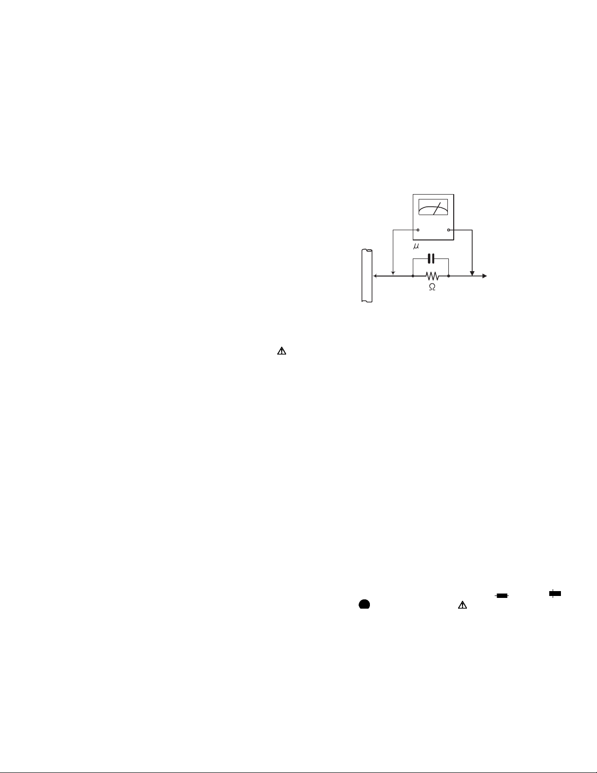
(5) Leakage shock hazard testing
After reassembling the product, always perform an isolation check on the exposed metal parts of the product (antenna terminals, knobs, metal cabinet, screw heads,
headphone jack, control shafts, etc.) to be sure the product
is safe to operate without danger of electrical shock.Do not
use a line isolation transformer during this check.
• Plug the AC line cord directly into the AC outlet. Using a
"Leakage Current Tester", measure the leakage current
from each exposed metal parts of the cabinet, particularly any exposed metal part having a return path to the
chassis, to a known good earth ground. Any leakage current must not exceed 0.5mA AC (r.m.s.).
• Alternate check method
Plug the AC line cord directly into the AC outlet. Use an
AC voltmeter having, 1,000Ω per volt or more sensitivity
in the following manner. Connect a 1,500Ω 10W resistor
paralleled by a 0.15µF AC-type capacitor between an ex-
posed metal part and a known good earth ground.
Measure the AC voltage across the resistor with the AC
voltmeter.
Move the resistor connection to each exposed metal
part, particularly any exposed metal part having a return
path to the chassis, and measure the AC voltage across
the resistor. Now, reverse the plug in the AC outlet and
repeat each measurement. Voltage measured any must
not exceed 0.75 V AC (r.m.s.). This corresponds to 0.5
mA AC (r.m.s.).
AC VOLTMETER
(Having 1000
ohms/volts,
or more sensitivity)
0.15 F AC TYPE
Place this
probe on
1500 10W
Good earth ground
1.2 Warning
(1) This equipment has been designed and manufactured to
meet international safety standards.
(2) It is the legal responsibility of the repairer to ensure that
these safety standards are maintained.
(3) Repairs must be made in accordance with the relevant
safety standards.
(4) It is essential that safety critical components are replaced
by approved parts.
(5) If mains voltage selector is provided, check setting for local
voltage.
1.3 Caution
Burrs formed during molding may be left over on some parts
of the chassis.
Therefore, pay attention to such burrs in the case of preforming repair of this system.
1.4 Critical parts for safety
In regard with component parts appearing on the silk-screen
printed side (parts side) of the PWB diagrams, the parts that are
printed over with black such as the resistor ( ), diode ( )
and ICP ( ) or identified by the " " mark nearby are critical
for safety. When replacing them, be sure to use the parts of the
same type and rating as specified by the manufacturer.
(This regulation dose not Except the J and C version)
each exposed
metal part.
(No.MB455)1-3
Page 4

SECTION 2
SPECIFIC SERVICE INSTRUCTIONS
This service manual does not describe SPECIFIC SERVICE INSTRUCTIONS.
1-4 (No.MB455)
Page 5
SECTION 3
A
A
DISASSEMBLY
3.1 Main body section
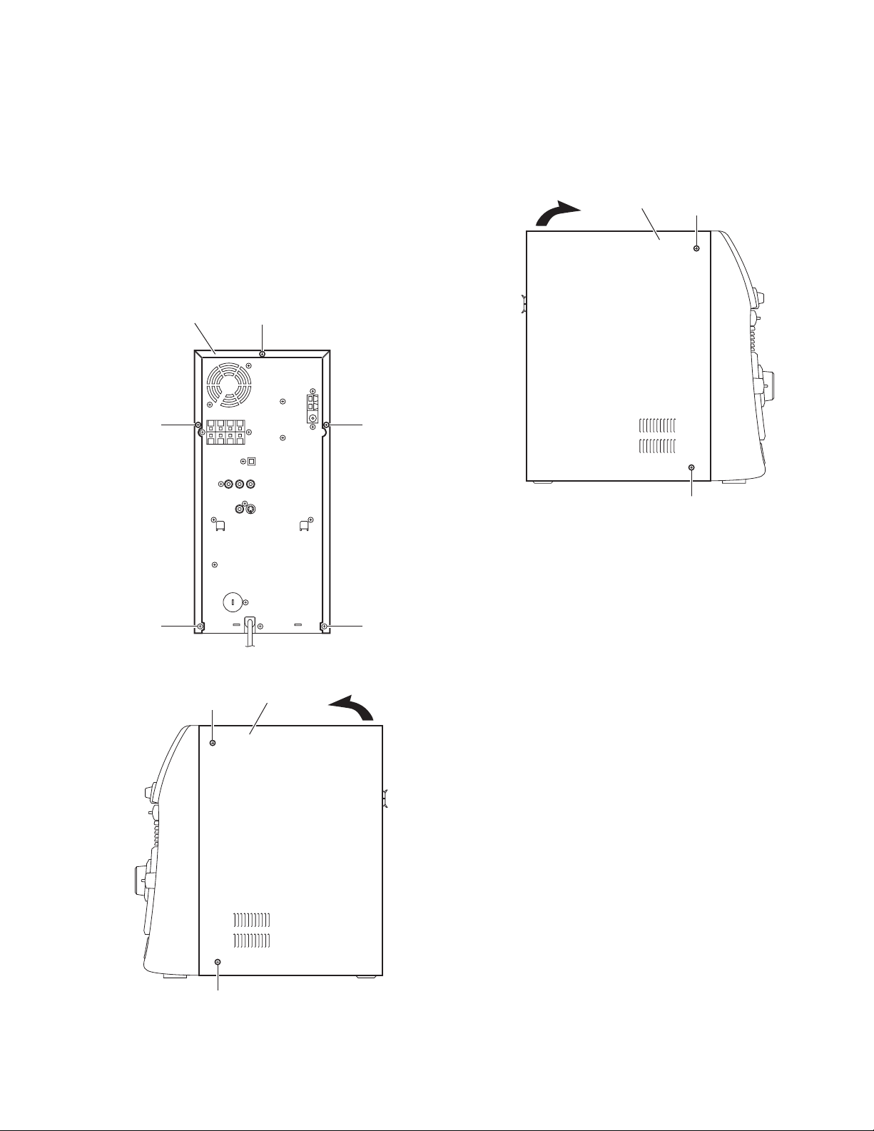
3.1.1 Removing the metal cover
(See Figs.1 to 3)
(1) From the back side of the main body, remove the five
screws A attaching the metal cover. (See Fig.1.)
(2) From the both sides of the main body, remove the four
screws A attaching the metal cover. (See Figs.2 and 3.)
(3) Remove the metal cover from the main body while lifting
the rear section of the metal cover in the direction of the arrow. (See Figs.2 and 3.)
Metal cover
A
Metal cover
A
A
A
A
Fig.3
A
Fig.1
Metal cover
A
Fig.2
(No.MB455)1-5
Page 6
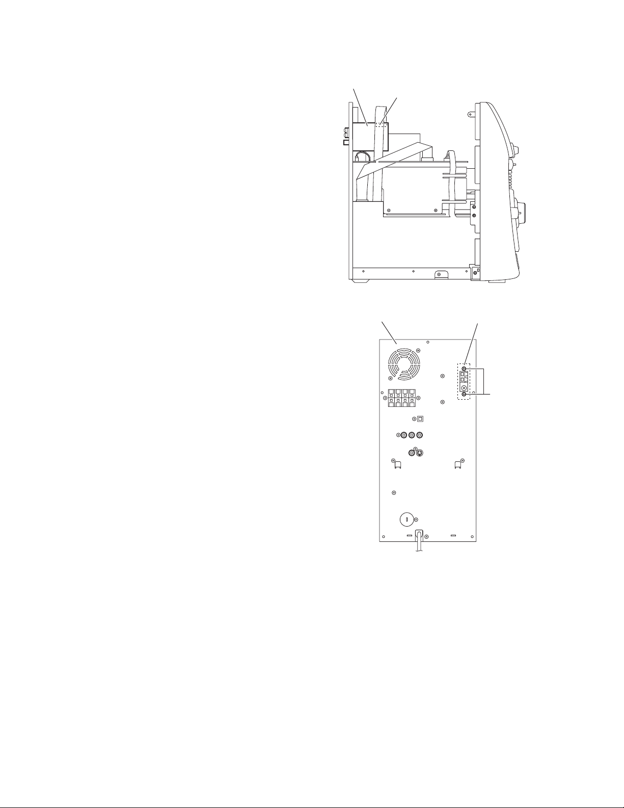
3.1.2 Removing the tuner
(See Figs.4 and 5)
• Remove the metal cover.
(1) From the left side of the main body, disconnect the card
wire from the connector on the tuner. (See Fig.4.)
(2) From the back side of the main body, remove the two
screws B attaching the tuner to the rear panel. (See Fig.5.)
Tuner
Connector
Fig.4
Rear panel
Tuner
B
Fig.5
1-6 (No.MB455)
Page 7

3.1.3 Removing the fan motor
(See Figs.6 and 7)
• Remove the metal cover.
(1) From the top side of the main body, disconnect the wire
from the connector FAN101
Fig.6.)
(2) From the back side of the main body, remove the two
screws C attaching the fan motor to the rear panel. (See
Fig.7.)
(3) Take out the fan motor from the main body.
on the amplifier board. (See
FAN101
Fan motor
Fan motor
C
Amplifier board
Fig.6
Rear panel
Fig.7
(No.MB455)1-7
Page 8

3.1.4 Removing the rear panel
(See Fig.8)
• Remove the metal cover.
(1) From the back side of the main body, remove the fifteen
screws D and screw E attaching the rear panel.
(2) Remove the sections a toward this side and remove the
rear panel from the sections b.
Rear panel
3.1.5 Removing the video board
(See Fig.9)
• Remove the metal cover and rear panel.
From the back side of the main body, disconnect the card wire
from the connector CN101
on the video board.
D
a a
D
b
D
Fig.8
D
E
b
CN101
1-8 (No.MB455)
Video board
Fig.9
Page 9

3.1.6 Removing the fuse board and voltage selector board
(See Fig.10)
• Remove the metal cover and rear panel.
From the back side of the main body, disconnect the wires from
the connectors (DCW06
the fuse board with the voltage selector board.
3.1.7 Removing the amplifier board
(See Fig.11)
• Remove the metal cover and rear panel.
(1) From the top side of the main body, disconnect the wire of
the fan motor from the connector FAN101
board.
(2) Disconnect the wire from the connector FAN102
amplifier board and remove the wire from the slot c.
(3) Disconnect the wires from the connectors (AW102,
, CW108) on the amplifier board.
AW105
(4) Disconnect the card wire from the connector AW104 on the
amplifier board.
(5) Disconnect the card wire from the connector AW101
amplifier board and remove the card wire from the slot c.
(6) Remove the card wire of the tuner from the slot c.
Reference:
• Remove the tuner as required.
• When connecting the each wire, pass them through
the slot c as before.
(7) Remove the screw F and take out the amplifier board from
the main body.
, DCW07) on the fuse board and remove
on the amplifier
on the
on the
Fuse board
DCW07
Amplifier board
AW101
FAN101
FAN102
Card wire (for the tuner)
DCW06
Voltage selector board
Fig.10
F
CW108
c
AW104
AW102
AW105
Fig.11
(No.MB455)1-9
Page 10

3.1.8 Removing the power amplifier ICs
(See Figs.12 to 14)
• Remove the metal cover, rear panel and amplifier board.
(1) From the forward side of the amplifier board, remove the
four screws G and screw H attaching the power amplifier
ICs to the heat sink. (See Figs.12 and 13.)
(2) From the reverse side of the amplifier board, remove the
three screws J attaching the heat sink. (See Fig.14.)
(3) Remove the soldered sections (d, e, f) and remove the
power amplifier ICs from the forward side of the amplifier
board. (See Fig.14.)
Power amplifier IC (AIC01)
Heat sink
G
Amplifier board
Fig.12
Power amplifier IC (AIC02)
Power amplifier IC (PIC02)
Heat sink
G H
Amplifier board
Fig.13
d
e
J
f
Amplifier board
Fig.14
1-10 (No.MB455)
Page 11

3.1.9 Removing the 5DVD changer mechanism assembly
(See Figs.15 to 19)
• Remove the metal cover, rear panel, video board and amplifier
board.
(1) From the right side of the main body, remove the card wire
from the sections g of the shield. (See Fig.15.)
(2) From the left side of the main body, remove the wire from
the sections h of the shield. (See Fig.16.)
(3) From the both sides of the main body, remove the four
screws K and remove the shield from the main body. (See
Figs.15 and 16.)
(4) Disconnect the wires from the connectors (DCW02
DCW04
(5) From the both sides of the main body, remove the four
screws M and remove the 5DVD changer mechanism assembly from the main body in the direction of the arrow.
(See Figs.17 and 18.)
(6) Disconnect the card wire from the connector CW104
forward side of the main board. (See Fig.18.)
(7) From the top side of the 5DVD changer mechanism as-
sembly, remove the four screws N and remove the base 1
and base 2. (See Fig.19.)
(8) From the bottom side of the 5DVD changer mechanism as-
sembly, disconnect the card wire from the connector
CN701
Reference:
When removing the tray panels, release the claws j of the tray
panel and remove the five tray panels from the 5DVD changer
mechanism assembly. (See Fig.19.)
Note:
When releasing the claws j, take care not to break them. (See
Fig.19.)
, DCW05) on the DVD power board. (See Fig.17.)
on the
on the DVD servo control board. (See Fig.19.)
g
Shield
,
K
Fig.15
Shield
h
M
DCW02
K
Fig.16
5DVD changer mechanism assembly
DCW05
DVD power board
Fig.17
DCW04
(No.MB455)1-11
Page 12

5DVD changer mechanism assembly
M
Main board
Tray panels
j
j
CW104
Fig.18
5DVD changer mechanism assembly
NN
Base 1
CN701
NN
DVD servo
control board
Base 2
1-12 (No.MB455)
Fig.19
Page 13

3.1.10 Removing the DVD power board
(See Fig.20)
• Remove the metal cover, rear panel, video board, amplifier
board and 5DVD changer mechanism assembly.
(1) From the back side of the base 2, disconnect the card wires
from the connectors (AW103
board.
(2) Disconnect the wire from the connector AW104
DVD power board.
(3) Remove the three screws P attach the DVD power board
on the base 2.
, AW106) on the DVD power
on the
AW104
AW106
AW103
3.1.11 Removing the power transformer
(See Fig.21)
• Remove the metal cover, rear panel, video board, fuse board,
voltage selector board, amplifier board and 5DVD changer
mechanism assembly.
(1) Remove the four screws Q attaching the power transformer
on the bottom chassis.
(2) Take out the power transformer.
3.1.12 Removing the main board
(See Figs.21 and 22)
• Remove the metal cover, rear panel, video board, amplifier
board and 5DVD changer mechanism assembly.
(1) From the top side of the main body, remove the screw R at-
taching the earth wires on the bottom chassis. (See
Fig.21.)
(2) Remove the screw S attaching the main board. (See
Fig.22.)
(3) Disconnect the connectors (CW101
the main board from the front panel assembly in the direction of the arrow. (See Fig.22.)
, CW102, CW105) on
P
DVD power board
Main board
Earth wires
Fig.20
R
Bottom chassis
Q
Fig.21
P
Base 2
Power transformer
Q
Q
Front panel assembly
Main board
S
Fig.22
CW105
CW102
CW101
(No.MB455)1-13
Page 14

3.1.13 Removing the front panel assembly
(See Figs.21, 23 to 25)
• Remove the metal cover, rear panel, video board, amplifier
board and 5DVD changer mechanism assembly.
(1) From the top side of the main body, remove the screw R at-
taching the earth wires on the bottom chassis. (See
Fig.21.)
(2) From the both sides of the main body, remove the two
screws T attaching the front panel assembly. (See Figs.23
and 24.)
(3) From the both and bottom sides of the main body, release
the joints (k, m) and remove the front panel assembly from
the main body in the direction of the arrow. (See Figs.23 to
25.)
Front panel assembly
k
T
Fig.23
Front panel assembly
1-14 (No.MB455)
Fig.24
Front panel assembly
Fig.25
T
k
m
Page 15

3.1.14 Removing the FL board
(See Fig.26)
• Remove the metal cover, rear panel, video board, amplifier
board, 5DVD changer mechanism assembly and front panel
assembly.
(1) From the inside of the front panel assembly, remove the
four screws U attaching the FL board.
(2) Take out the FL board from the front panel assembly and
disconnect the card wire from the connector FW102
forward side of the FL board.
on the
Front panel assembly
U
U
FW102
Fig.26
FL board
(No.MB455)1-15
Page 16

3.1.15 Removing the switch board
(See Figs.27 and 28)
• Remove the metal cover, rear panel, video board, amplifier
board, 5DVD changer mechanism assembly, front panel assembly and FL board.
(1) From the inside of the front panel assembly, remove the
spacer on the switch board.
(2) Remove the five screws U attaching the switch board. (See
Fig.27.)
(3) Take out the switch board while lifting it from the front panel
assembly little by little.
Reference:
The preset knob is removed from the front side simultaneously. (See Fig.28.)
(4) Take out the switch board from the front panel assembly
and disconnect the card wire from the connector FW201
the forward side of the switch board. (See Fig.27.)
on
FW201
U
Spacer
3.1.16 Removing the volume board
(See Figs.28 and 29)
• Remove the metal cover, rear panel, video board, amplifier
board, 5DVD changer mechanism assembly and front panel
assembly.
(1) From the front side of the front panel assembly, pull out the
volume knob in the direction of the arrow. (See Fig.28.)
(2) From the inside of the front panel assembly, disconnect the
card wire from the connector FW301
(See Fig.29.)
(3) Remove the seven screws U attaching the volume board.
(See Fig.29.)
(4) Take out the volume board from the front panel assembly
and disconnect the wires from the connectors (FW307
FW308) on the forward side of the volume board. (See
Fig.29.)
3.1.17 Removing the jack board
(See Fig.29)
• Remove the metal cover, rear panel, video board, amplifier
board, 5DVD changer mechanism assembly, front panel as-
sembly and volume board.
Remove the three screws U and take out the jack board from the
front panel assembly.
on the volume board.
U
Fig.27
Preset knob
,
Volume knob
Fig.28
Volume board
Switch board
Front panel assembly
U
1-16 (No.MB455)
FW301
FW307
Jack board
Fig.29
U
FW308
UU
UU
Page 17

SECTION 4
ADJUSTMENT
This service manual does not describe ADJUSTMENT.
SECTION 5
TROUBLESHOOTING
This service manual does not describe TROUBLESHOOTING.
(No.MB455)1-17
Page 18

Victor Company of Japan, Limited
AV & MULTIMEDIA COMPANY AUDIO/VIDEO SYSTEMS CATEGORY 10-1,1chome,Ohwatari-machi,Maebashi-city,371-8543,Japan
(No.MB455)
Printed in Japan
VPT
 Loading...