

Page 1
HA-SU700 (E)
SERVICE MANUAL
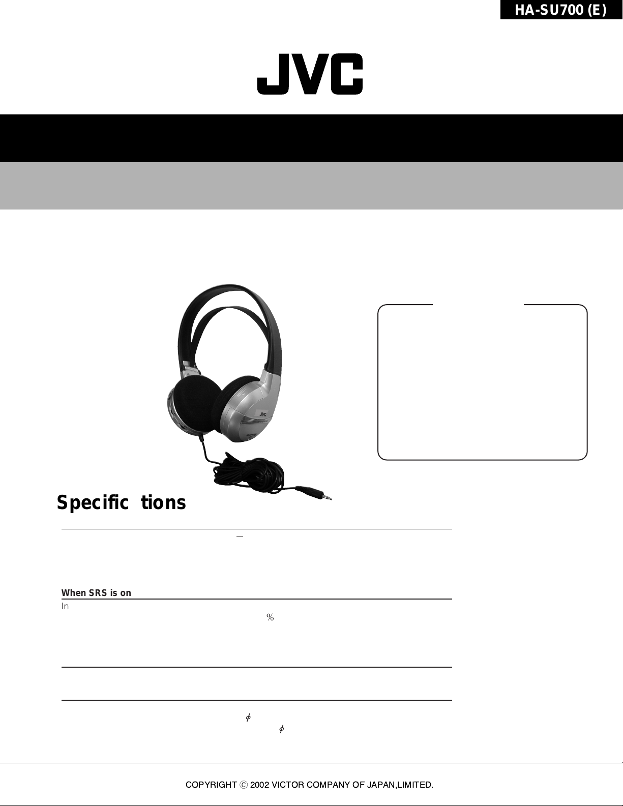
SURROUND SOUND STEREO HEADPHONES
HA-SU700 (E)
Specifications
1. Instructions
2. Disassembly
3. Servicing Guidelines
4. Block View Inside IC
5. Block Diagram
6. Wiring Diagram
7. Print Circuit Board
8. Schematic Diagram
9. Electric Parts List
10. Exploded View
11. Mechanical Parts List
12. Packing Method
13. Packing Materials Parts List
14. Accessories List
Specifications
General Specifications
Frequency response : 18 Hz 22,000 Hz
Power supply : AA (R6P) battery x 2 (DC 3 V)
Cord : 7 m (22.97 ft)
Mass : 280 g (9.88 oz)
(including AA (R6P) battery x 2, without cord)
When SRS is on
Input impedance : 500 Ω
Distortion : Less than 0.3 (at 1 kHz)
Battery running time : Approx, 70 hours (when manganese battry is used)
Approx, 140 hours (when alkaline battry is used)
(running time varies depending on the conditions of use.)
When SRS is off
Sensitivity : 94 dB/1 mW
Contents
.....................................
.................................................
................................................
...................................
...................................
.............................................
...........................................
......................................
.....................................
........................................
.............................................
.................................
..........................................
......................
.........................................
Front cover
2
6
7
8
8
9
10
11
12
13
13
14
14
14
Provided Accessories
Instructions x 2
24K gold-plated plug adaptor x 1 (converts 3.5 mm Stereo mini plug to
6.3 mm Standard stereo plug)
AA (R6P) battery x 2
*Design and specifications subjsct to change without notice.
COPYRIGHTC2002 VICTOR COMPANY OF JAPAN,LIMITED.
No.70266
Apr.2002
Page 2
HA-SU700 (E)
©2002 VICTOR COMPANY OF JAPAN, LIMITED.
VICTOR COMPANY OF JAPAN, LIMITED
J5500-112A
SURROUND SOUND STEREO HEADPHONES
SURROUND SOUND-STEREO-KOPFHÖRER
CASQUE STÉRÉO SURROUND
CUFFIE STEREO AD EFFETTO SURROUND
HA-SU700 (E)
ENGLISH
DEUTSCH
FRANÇAIS
ITALIANO
INSTRUCTIONS
BEDIENUNGSANLEITUNG
MANUEL D’INSTRUCTIONS
ISTRUZIONI
SPECIFICATIONS
General Specifications
Frequency response : 18 Hz — 22,000 Hz
Power requirements : AA (R6P) battery x 2 (DC 3V)
Cord length : 7 m (22.97 ft)
Mass : 280 g (9.88 oz) (including AA
(R6P) battery x 2, without cord)
When SRS is on
Input impedance : 500 Ω
Distortion : Less than 0.3% (at 1 kHz)
Battery running time : Approx. 70 hours (when
manganese battery is used)
Approx. 140 hours (when alkaline
battery is used) (running time
varies depending on the conditions
of use.)
When SRS is off
Sensitivity : 94 dB/1 mW
Provided Accessories
Instructions x 2
24K gold-plated plug adapter x 1 (converts ø3.5 mm stereo
miniplug to ø6.3 mm standard stereo plug)
AA (R6P) battery x 2
*
Design and specifications subject to change without
notice.
ENGLISH
FRANÇAIS
DEUTSCH
ITALIANO
CARACTERISTIQUES
Caractéristiques générales
Réponse en fréquence : 18 Hz — 22.000 Hz
Alimentation : 2 piles AA (R6P) (3 Vcc)
Longueur du cordon : 7 m
Poids : 280 g (avec deux piles AA (R6P),
sans cordon)
Interrupteur SRS enclenché
Impédance d’entrée : 500 Ω
Distorsion : Inférieure à 0,3% (à 1 kHz)
Autonomie des piles : Environ 70 heures (avec piles au
manganèse)
Environ 140 heures (avec piles
alcalines) (l’autonomie dépend des
conditions d’utilisation.)
Interrupteur SRS coupé
Sensibilité : 94 dB/1 mW
Accessoires fournis d’origine
2 Modes d’emploi
1 Adaptateur de fiche plaqué or 24 carat (conversion de la
minifiche stéréo ø3,5 mm en fiche stéréo standard ø6,3 mm)
2 piles AA (R6P)
*
Modèle et caractéristiques sous réserve de modification
sans avis préalable.
TECHNISCHE DATEN
Allgemeine Angaben
Frequenzgang : 18 Hz — 22.000 Hz
Stromversorgung :
2 Mignonbatterien (AA/R6P), (3V DC)
Kabellänge : 7 m
Gewicht : 280 g (inkl. 2 Mignonbatterien
(AA/R6P), ohne Kabel)
Bei eingeschalteter SRS-Funktion
Eingangsimpedanz : 500 Ω
Klirrfaktor : < 0,3% (bei 1 kHz)
Batteriebetriebsdauer : ca. 70 Std. bei Verwendung von
Manganbatterien
ca. 140 Std. bei Verwendung von
Alkalinebatterien (Die
Betriebsdauer hängt von den
Einsatzbedingungen ab.)
Bei ausgeschalteter SRS-Funktion
Kennschalldruck : 94 dB / 1 mW
Mitgeliefertes Zubehör
2 Bedienungsanleitungen
Vergoldeter Adapter (24 K) zur Umsetzung von ø3,5 mm
Stereo-Miniklinke auf ø6,3 mm Stereo-Standardklinke
2 Mignonbatterien (AA/R6P)
*
Änderung der Ausstattungsmerkmale und der technischen
Daten ohne vorherige Ankündigung vorbehalten.
CARATTERISTICHE TECNICHE
Caratteristiche generali
Risposta in frequenza : 18 Hz — 22.000 Hz
Alimentazione : Batteria AA (R6P) x 2 (DC 3V)
Lunghezza del cavo : 7 m
Massa : 280 g [incluse due batterie AA
(R6P), senza cavo]
Con SRS in posizione ON
Impedenza in ingresso : 500 Ω
Distorsione : Inferiore a 0,3% (a 1 kHz)
Autonomia delle batterie : Circa 70 ore (con batterie al
manganese)
Circa 140 ore (con batterie
alcaline) (l’autonomia delle batterie
dipende dalle condizioni d’uso)
Con SRS in posizione OFF
Sensibilità : 94 dB/1 mW
Accessori forniti in dotazione
Istruzioni x 2
Adattatore per spinotto placcato in oro a 24K (converte
miniplug stereo ø3,5 mm in spinotto stereo standard ø6,3 mm)
2 pile AA (R6P)
*
Il design e le caratteristiche tecniche sono soggetti a
modifiche senza preavviso.
1.Instructions
2(No.70266)
Page 3
“SOME DO’S AND DON’TS ON THE SAFE USE OF EQUIPMENT
”
This equipment has been designed and manufactured to meet international safety standards
but, like any electrical apparatus, care must be taken if you are to obtain the best results and
safety is to be assured.
Do
read the operating instructions before you attempt to use the equipment.
Do
ensure that all electrical connections (including the plug, extension cord and inter-
connections between pieces of equipment) are properly made and in accordance
with the manufacturer
’s instructions. Switch off and withdraw the plug when making
or changing connections.
Do
consult your dealer if you are ever in doubt about the installation or operation or
safety of your equipment.
Do
be careful with glass panels or doors on equipment.
DON’T
continue to operate the equipment if you are in any doubt about it working normally,
or if it is damaged in any way
– switch off – withdraw the plug and consult your
dealer.
DON’T
remove any fixed cover as this may expose dangerous voltages.
DON’T
leave equipment switched on when it is unattended unless it is specifically stated that
it is designed for unattended operation or has a standby mode. Switch off using the
switch on the equipment and make sure that your family know how to do this.
Special arrangements may need to be made for infirm or handicapped people.
DON’T
use equipment such as personal stereos or radios so that you are distracted from the
requirements of road safety. It is illegal to watch television when driving.
DON’T
listen to headphones at high volume as such use can permanently damage your
hearing.
DON’T
obstruct the ventilation of the equipment, for example with curtains or on soft
furnishings.
Overheating will cause damage and shorten the life of the equipment.
DON’T
use makeshift stands and NEVER fix legs with wood screws. To ensure complete
safety always fit the manufacturer
’s approved stand or legs with the fixing screws
supplied according to the instructions.
DON’T
allow electrical equipment to be exposed to rain or moisture.
ABOVE ALL
NEVER let anyone especially children push anything into holes, slots or any other opening in
the case. This could result in a fatal electrical shock.
NEVER guess or make changes with electrical equipment of any kind.
It is better to be safe than sorry!
WARNING:
TO REDUCE THE RISK OF FIRE OR ELECTRIC
SHOCK, DO NOT EXPOSE THIS APPLIANCE TO
RAIN OR MOISTURE.
AVERTISSEMENT:
POUR RÉDUIRE LES RISQUES D
’INCENDIE OU
DE CHOC ÉLECTRIQUE, NE PAS EXPOSER CET
APPAREIL À LA PLUIE NI À L’HUMIDITÉ.
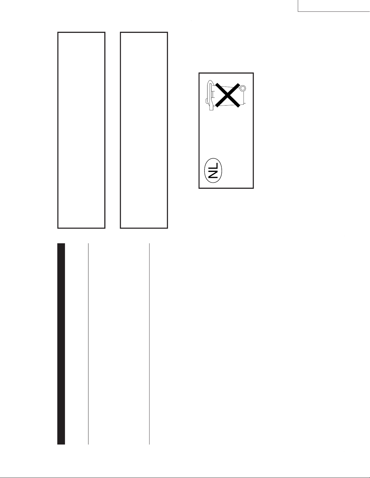
Gebruikte batterijen
Niet weggooien,
maar inleveren als KCA.
HA-SU700 (E)
(No.70266)3
Page 4
HA-SU700 (E)
ENGLISH
FEATURES
● Built-in surround sound circuit, exclusively designed for headphones.
● Surround sound control allows surround effects to be switched and adjusted
according to listener preference.
● Soft comfort-fit headband automatically adjusts to fit the listener
’s head.
● Usable as headphones with volume control.
Thank you for purchasing this JVC product.
Before you begin operating this unit, please read the instructions carefully to be sure you
get the best possible performance.
If you have any questions, consult your JVC dealer.
1
2
3
4
5
6
7
8
and
symbol are trademarks of SRS Labs, Inc.
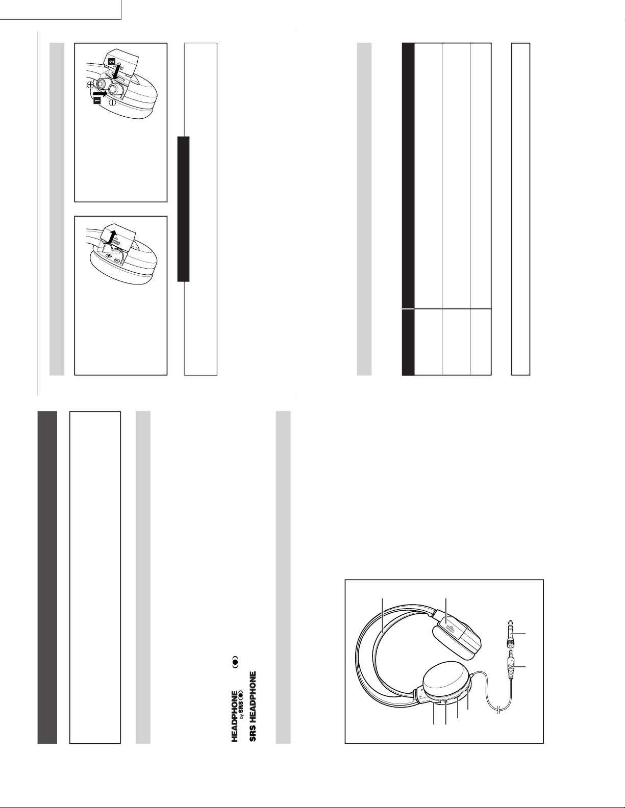
2
ON/OFF (Power/Surround Switch)
Switches Power and Surround ON or OFF
simultaneously.
When the SRS switch is turned to ON, the
HA-SU700’s power turns on, and the Surround
circuit operates.
To save battery power, be sure to turn the SRS
switch OFF when not in use.
3
SURROUND (Surround level control)
Allows surround effect level to be adjusted
(when Surround is ON).
4
VOL (Volume control)
Enables headphone volume adjustment.
5
Soft comfort-fit headband
Automatically adjusts head band to fit when you
put the headphones on your head.
6
Battery Cover
Open this cover and insert two AA (R6P)
batteries in the battery compartment to use
these headphones as surround sound
headphones.
7
Audio input cord and plug
7 m cord and 3.5 mm dia. stereo miniplug.
8
Plug adapter
Converts a stereo miniplug to a standard stereo
plug.
1
SRS (Power/Surround Indicator)
Indicates Power/Surround ON and OFF.
Lit : Power and Surround are ON.
Unlit :Power and Surround are OFF.
NAMES OF PARTS AND THEIR FUNCTIONS
technology is incorporated under license from SRS Labs, Inc.
How to insert batteries
TROUBLE SHOOTING
What appears to be a malfunction may not always be serious. First, make sure
to check the following.
1
Remove the
battery cover on
the right side of
the headphones.
2
Insert two AA
(R6P) batteries
as shown, and
then close the
cover.
When to replace the batteries
You will need to replace the batteries when the indicator becomes dim and/or sound is
distorted when the SRS switch is ON.
Note:
Turn down the volume of connected audio source equipment to minimum when inserting or removing
the headphone plug. Otherwise the HA-SU700 and/or the connected device may be damaged.
Do not connect headphones to the line output terminals. You will be unable to obtain
sufficient volume.
When the SRS switch is turned ON or OFF, you may hear a clicking noise.
Turn the volume of the HA-SU700 down to minimum when turning the SRS switch ON or OFF.
Even at the same volume position, the headphone volume may vary depending on the SRS switch
position. Volume is also affected by the connected device and the HA-SU700
’s surround level.
Depending on the connected device, noise may be produced by interference with the headphone
terminal. In this case, turn up the volume of the connected device as high as it will go without
distorting the sound, and turn down the volume of HA-SU700. This might help reduce the noise.
Problems
No sound/
low sound
Sound
distortion
No surround
effect
Measures (Remedy)
䡲
Check the volume of connected device.
䡲
Adjust the headphone sound volume.
䡲
Replace the batteries.
䡲
Adjust the headphone sound volume, after turning down the volume of
connected device to a level where the sound is not distorted.
䡲
Replace the batteries.
䡲
Surround effects cannot be obtained if the input sound is monaural.
Serious malfunction
If a serious malfunction occurs, stop using the unit immediately and consult your local JVC dealer.
4(No.70266)
Page 5

HA-SU700 (E)
ENGLISH
CAUTIONS
Headphones
1
For your safety
…
• Never use the headphones when driving a car, motorcycle, or bicycle. This could result in an accident.
• Pay close attention to traffic around you when using the headphones while walking. Not doing so could
result in an accident.
• Be careful not to turn the sound volume up too high when using the headphones. Your hearing can be
damaged by listening to sounds at excessive volume for long periods.
• Do not disassemble or modify the headphones.
• Do not allow inflammables, water or metallic objects to enter the headphones.
2
Avoid using the headphones
…
• in places subject to excessive humidity or dust.
• in places subject to extremely high (over 40
°C or 104°F) or extremely low (under 0
°C or 32°F)
temperatures.
3
DO NOT leave the headphones
…
• in direct sunlight.
• near a heater.
4
To protect the headphones, DO NOT
…
• allow them to get wet.
• drop them or strike them against hard objects.
䡲 Be careful not to add power that exceeds the headphones
’ input capacity. This may result in distorted sound and
could damage the oscillation board.
䡲 When disconnecting the headphones, grasp the headphone plug. Do not pull on the cord.
Battery
If the batteries are used incorrectly, they may leak, heat or explode, and may cause fire, injury or soiling.
Make note of the following:
1
Use only AA (R6P) batteries.
2
Use only the batteries specified for use with these headphones.
3
Insert batteries with the (+) and (
–) polarities correctly positioned, following the indications on the
equipment.
4
Do not use a new battery with an old one, and do not use batteries holding different amounts of charge
together.
5
Do not throw batteries in a fire or heat them.
6
Do not short-circuit the positive (+) and negative (
–) terminals. Also, do not carry or store them with small
metallic objects such as necklaces or coins.
7
Do not deform, take apart, modify or directly solder the batteries.
8
Do not remove or damage the covering tube.
9
If you notice phenomena that has never happened before, such as leakage, colour change or deformity,
stop using the batteries.
10
If any liquid from the batteries gets into your eyes, it may cause blindness. If battery liquid does get into
your eyes, do not rub them , but instead immediately wash them thoroughly with clean water, then
consult a doctor at once. Also, should any liquid from the rechargeable batteries get onto your skin or
clothes, it may burn your skin. In this case, wash with clean water immediately.
11
Do not immerse or wet the batteries in water.
12
Do not use or leave the batteries in an area where the temperature becomes significantly higher, such as
in direct sunlight, inside a car on a hot day or near heat-generating equipment.
13
Do not subject the batteries to strong shocks or throw them.
14
When discarding the batteries, cover the positive (+) and negative (
–) terminals with adhesive tapes.
15
Be sure to read the cautions on the batteries.
(No.70266)5
Page 6

HA-SU700 (E)
2.Disassembly
™
2
7
1
+
@
~
9
5
$
%
)
&
*
(
^
#
3
4
¡
8
0
!
=
-
6
_
1.Remove the Battery Cover Assembly 1 and then take out the two batteries,
2.Remove the Ear pad 2,3 and remove the Screw 4,5.
3.The Housing Assembly 6,7 and the Frame 8,9 are separated.
4.Remove the Cord Assembly 0.
5.Remove the Print Circuit Board -.
6.Remove the Screw =,~, then remove the Stopper !,@ and the Protector #,$.
7.Remove the Screw %,^, then remove the Unit Holder &,*.
8.Remove the Driver Unit (,).
9.Remove the Coil Sping _,+ and the Sub Band ¡ then remove the Headband Assembly ™.
10.When reassemble the headphones, be carefull of placing the wires.
6(No.70266)
Page 7

1. Measurement setup
1Audio signal generator
(output impedance : 600
Ω
)
2VTVM
3Oscilloscope
4Tester
2. YES Normal
NO When the correct voltage
or waveform does not appear
New Battery : R6P/AA x 2
Surround : max
Vol. : max
Audio signal generator
1 V RMS, 1 kHz sine wave
Lch + Rch input
or
Lch or Rch input
Symptom Input signal Check point Correct voltage / waveform Check point and defective point
Symptom Input signal Check point Correct voltage / waveform Check point and defective point
No sound
No power
Surround volume
cannot be
adjusted
No sound
or
L/R unbalance
Lch + Rch input
Lch + Rch input
Lch + Rch input
Lch + Rch input
Cord Assembly connection
VR1 connection part
SW1 connection part
Driver Unit connection part
1
2
3
4
1
2
3
4
7
8
9
0
5
6
SRS switch : OFF
SRS switch : ON
Approx. 70 mV p_p
Approx. D.C 3.0 V
Between land BATT(+)
and BATT(-)
Cord Assembly connection
VR1 connection part
Land by the side of SW1
of R14(Lch)
and R16(Rch)
Approx. 0.8 V p
_
p
Approx. 110 mV p
_
p
Approx. 380 mV p
_
p
Approx. 220 mV p
_
p
(no signal)
NO Cord Assembly is cut, or
VR1, SW1 defective.
Check peripheral circuits
YES Check connection wires and Driver Unit.
NO Cord Assembly is cut, or
VR1, SW1 defective.
Check peripheral circuits
YES Check 5
NO Check IC1 pin1(Lch input) and pin16(Rch
input), peripheral circuits.
YES Check 6
IC1 pin7 Lch Output
IC1 pin10 Rch Output
NO Check IC2 pin7 and pin6,
Check peripheral circuits.
YES Check Driver Unit,wire.
NO Check IC1.
Check peripheral circuits.
YES Check IC2.
Check peripheral circuits.
NO Check peripheral circuits.
Check between Lch and Rch
short circuits.
YES Check 9
NO Check Battery terminal
in the R side housing.
Wires is cut.
YES Check SW1, peripheral circuits.
SW1 defective.
Lch input
Rch input
Lch input
Rch input
------
IC2 pin1 Lch Output
IC2 pin3 Rch Output
IC1 pin16 Rch Input
IC1 pin1 Lch Input
IC1 pin10 Rch Output
IC1 pin7 Lch Output
3.Servicing Guidelines
HA-SU700 (E)
(No.70266)7
Page 8

HA-SU700 (E)
4.Block View Inside IC
Lin
W out
Win
MODE
Filter
Filter
L out
GND
1
2
3
4
5
6
7
8
NJM2190V
5.Block Diagram
IC1
#
@
!
~
=
-
0
9
Rin
V REF
REF in
Vcc /2
Filter
Filter
R out
Vcc
B Input
B+ Input
A+ Input
A Input
1
2
3
4
NJM2073M
IC2
8
GND
7
Output B
6
Vcc
5
Output A
Lch
INPUT
Rch
8(No.70266)
VR1
500
SW1
R6P/AA
Battery x 2
DC 3.0V
Rch
Lch
1
16
LED1
IC1
NJM2190V
EXT.
FILTER
VR2
50 k
IC2
NJM
2073M
77
MATRIX
10 6
93215
AMP
AMP
L-SP
3
OUTPUT
1
R-SP
Page 9

6.Wiring Diagram
Left
HA-SU700 (E)
Red
Green
White
From Cord Assembly
Green
Black
Red
Red
to Driver Unit (Left)
White
to Driver Unit and
Battery Terminal (Right)
Right
near the Battery Terminal
"BK" Black lead
"RED" Red lead
(No.70266)9
Page 10

HA-SU700 (E)
7.Print Circuit Board
P.C. Board
D
C
B
shows the B(+) power supply
shows the ground
(
shows others
)
A
1 2 3 4
Back side Surface
P.C. Board Location
Symbol No. Location Symbol No. Location Symbol No. Location Symbol No. Location
IC1
IC2
LED1
VR1
VR2
R1
R2
R3
R4
R5
R6
R7
R8
R9
R10
R11
ICs
Diode
Resistors
3B
3C
1D
1A
1B
2B
3B
4B
3B
4C
3D
2C
2D
2D
3C
3C
R12
R13
R14
R15
R16
R17
Capacitors
C1
C2
C3
C4
C5
C6
C7
C8
C9
C10
C11
Resistors
3B
4B
2B
2B
2C
2B
4A
2B
2A
2B
2A
4A
4B
3B
3B
4B
3B
C12
C13
C14
C15
C16
C17
C18
C19
C20
C21
C22
C23
C24
C25
C26
C27
C28
C29
Capacitors
2C
3C
3D
3C
3C
3C
4C
3D
4B
4B
3B
3C
2D
3B
3B
2C
2B
1C
Others
SW1
JW1
JW2
JW3
JW4
JW5
JW6
JW7
JW8
JW9
JW11
JW12
1C
2D
2C
3C
2C
4A
2B
2B
1C
2A
4C
2B
10(No.70266)
Page 11

8.Schematic Diagram
Notes:
1. The thick line ( ) is the B (+) power supply.
2. This circuit diagram is the reference diagram. Circuits and constans are subject to change without notice for
improvement.
3. Values printed in red show the voltares of each section measured by the tester (internal resistance 20 kOhms/V),
with the power switch ON.
4. Parts marked with
!(in the shaded area ) are safety parts.When replacing these, be sure to use only the
designated parts to ensure safety.
Use of Circuit Diagram
OUTPUT
INPUT
NORMAL
+
+
++
+
+
+
+
+
+
+
+
+
+
SURROUND
1.5
1.5
1.5
2.6
1.5
1.5
1.5
1.5
1.5
1.5
1.5
0.6
0.6
1.2
1.2
HA-SU700 (E)
(No.70266)11
Page 12

HA-SU700 (E)
9.Electric Parts List
P.C. Board Assembly
!
Ref. No.
!
ICs
IC1
IC2
Diode
LED1
Resistors
VR1
VR2
R1
R2
R3
R4
R5
R6
R7
R8
R9
R10
R11
R12
R13
R14
R15
R16
R17
Capacitors
C1
C2
C3
C4
C5
C6
C7
C8
C9
C10
C11
C12
C13
C14
C15
C16
C17
C18
C19
C20
C21
C22
C23
C24
C25
C26
C27
C28
C29
others
SW1
Parts No. Parts Name, Description
J33729-001
NJM2190V
NJM2073M
LTI-4211
JVJB03B-J52
JVJB03B-J54
QRD161J-103
QRD161J-223
QRD161J-103
QRD161J-103
QRD162J-100
QRD162J-100
QRD162J-102
QRD161J-181
QRD161J-472
QRD161J-472
QRD161J-181
QRD161J-563
QRD161J-563
QRD161J-273
QRD161J-472
QRD161J-273
QRD161J-472
QFM71HK-332M
QER41CM-106
QER41CM-106
QER41CM-106
QER41CM-106
QFM71HK-104
QER41CM-106
QER41CM-106
QFM71HK-472M
QER41CM-106
QEK40JM-477
QER41CM-106
QER41CM-106
QEK40JM-227
QEK40JM-227
QEK40JM-477
QCBB1HK-104
J47060-001
J47060-001
QEK41AM-107
QCBB1HK-104
QCBB1HK-104
QCBB1HK-470
QCBB1HK-470
QCBB1HK-221
QCBB1HK-221
QCBB1HK-820
QCBB1HK-820
QCBB1HK-102
JSSD142-J01
P.C. Board Assembly
The part will not be supplied as an
assembly.
IC
IC
LED(RED)
Variable Resistor
Variable Resistor
Resistor
Resistor
Resistor
Resistor
Resistor
Resistor
Resistor
Resistor
Resistor
Resistor
Resistor
Resistor
Resistor
Resistor
Resistor
Resistor
Resistor
Film Capacitor
E. Capacitor
E. Capacitor
E. Capacitor
E. Capacitor
Film Capacitor
E. Capacitor
E. Capacitor
Film. Capacitor
E. Capacitor
E. Capacitor
E. Capacitor
E. Capacitor
E. Capacitor
E. Capacitor
E. Capacitor
Cer. Capacitor
Cer. Capacitor
Cer. Capacitor
E. Capacitor
Cer. Capacitor
Cer. Capacitor
Cer. Capacitor
Cer. Capacitor
Cer. Capacitor
Cer. Capacitor
Cer. Capacitor
Cer. Capacitor
Cer. Capacitor
Slide Switch
500 ,B
50 k ,B
10 k 1/6 w
22 k 1/6 w
10 k 1/6 w
10 k 1/6 w
10 1/6 w
10 1/6 w
1 k 1/6 w
180 1/6 w
4.7 k 1/6 w
4.7 k 1/6 w
180 1/6 w
56 k 1/6 w
56 k 1/6 w
27 k 1/6 w
4.7 k 1/6 w
27 k 1/6 w
4.7 k 1/6 w
0.0033 F
10 F/16V
10 F/16V
10 F/16V
10 F/16V
0.1 F
10 F/16V
10 F/16V
0.0047 F
10 F/16V
470 F/6.3V
10 F/16V
10 F/16V
220 F/6.3V
220 F/6.3V
470 F/6.3V
0.1 F
0.22 F
0.22 F
100 F/10V
0.1 F
0.1 F
47 pF
47 pF
220 pF
220 pF
82 pF
82 pF
0.001 F
MISUNG
ELECTRONICS
JRC
JRC
LITEON
Parts marked (!) are safety parts. When replacing, be sure to use the specified one.
12(No.70266)
Page 13

10.Exploded View
HA-SU700 (E)
1
#
4
-
~
9
=
%
6
$
&
8
$
!
0
0
!
$
7
#
$
^
2
5
@
9
%
P.C. Board
Assembly
(Refer to Page 10)
3
~
11.Mechanical Parts List
Item No. Q'ty
!
1
2
3
4
5
6
7
8
9
10
11
12
13
14
15
16
17
18
19
20
Parts No. Parts Name
J33818-001
J33731-001
J33819-002
J33820-002
J33734-001
J33735-001
J33736-001
J33737-001
J47020-001
J47019-001
J47053-001
J47054-001
J47055-001
J47058-001
J47097-001
J47057-001
J47059-001
QYSPSG2608M
J46310-001
J47098-001
Headband Assembly
Sub Band
Housing L Assembly
Housing R Assembly
Frame L
Frame R
Protector L
Protector R
Stopper
Unit Holder
Battery Cover Assembly
Battery Terminal
Coil Spring
Driver Unit
Cord Assembly
Ear Pad
Screw
Screw
Serial Label
CE Label
1
with connecting wire
1
1
with ornament
1
with ornament
1
1
1
1
2
2
1
with battery terminal
2
2
2
1
with bushing
2
16
2
1
1
2x6
2.6x8
4mmx30mm
Description
Parts marked (!) are safety parts. When replacing, be sure to use the specified one.
(No.70266)13
Page 14

HA-SU700 (E)
12.Packing Method
1
4
7
6
2
3
5
13.Packing Materials Parts List
Item No.
!
1
2
3
4
5
Parts marked (!) are safety parts. When replacing, be sure to use the specified one.
Parts No. Parts name
J22073-001
J22074-001
J33748-002
J33749-002
J45251-001
Blister Cover
Packing Holder
Sheet
Sub Sheet
Serial Label
Q'ty
1
1
1
1
1
11mm x 50mm
14.Accessories List
8
0
9
Description
Item No.
!
6
7
!
!
Parts marked (!) are safety parts. When replacing, be sure to use the specified one.
14(No.70266)
8
9
10
Parts No. Parts name
J32699-001
J5500-112A
J5500-113A
BT-20066A
Plug Adapter
Battery (R6P/AA)
Instructions
Instructions
EEC Agency
Q'ty
1
2
1
1
1
24K gold-Plated
Commercialy available
English,German,French,Italian
Spanish,Dutch,Swedish,Finnish
Description
Page 15

-MEMO-
HA-SU700 (E)
(No.70266)15
Page 16

HA-SU700 (E)
VICTOR COMPANY OF JAPAN, LIMITED
COMMUNICATION NETWORK BUSINESS UNIT, 1644, SHIMOTSURUMA, YAMATO-SHI, KANAGAWA-KEN, 242-8514, JAPAN
(No.70266)
Printed in Japan
0204(V)
 Loading...