

JVC GZ-MG330HEK, GZ-MG330HER, GZ-MG330HEX, GZ-MG330HEZ, GZ-MG335HEK Service Manual
...
SERVICE MANUAL
HARD DISK CAMCORDER
YF227<Rev.001>20082SERVICE MANUALEVERIO G
GZ-MG330HEK, GZ-MG330HER,
GZ-MG330HEX, GZ-MG330HEZ,
GZ-MG335HEK, GZ-MG335HER,
GZ-MG335HEX, GZ-MG335HEZ,
GZ-MG340HEX, GZ-MG365HEK,
GZ-MG365HER, GZ-MG365HEX,
GZ-MG365HEZ
GZ-MG330HEKM, GZ-MG330HERM, GZ-MG330HEXM,
GZ-MG330HEZM, GZ-MG340HEXM [M8E302]
GZ-MG335HEKM, GZ-MG335HERM
GZ-MG335HEXM, GZ-MG335HEZM [M8E304]
GZ-MG365HEKM, GZ-MG365HERM
COPYRIGHT© 2008 Victor Company of Japan, Limited
Lead free solder used in the board (material : Sn-Ag-Cu, melting point : 219 Centigrade)
TABLE OF CONTENTS
1 PRECAUTIONS . . . . . . . . . . . . . . . . . . . . . . . . . . . . . . . . . . . . . . . . . . . . . . . . . . . . . . . . . . . . . . . . . . . . . . . 1-3
2 SPECIFIC SERVICE INSTRUCTIONS . . . . . . . . . . . . . . . . . . . . . . . . . . . . . . . . . . . . . . . . . . . . . . . . . . . . . . 1-5
3 DISASSEMBLY . . . . . . . . . . . . . . . . . . . . . . . . . . . . . . . . . . . . . . . . . . . . . . . . . . . . . . . . . . . . . . . . . . . . . . . 1-8
4 ADJUSTMENT . . . . . . . . . . . . . . . . . . . . . . . . . . . . . . . . . . . . . . . . . . . . . . . . . . . . . . . . . . . . . . . . . . . . . . . 1-19
5 TROUBLE SHOOTING. . . . . . . . . . . . . . . . . . . . . . . . . . . . . . . . . . . . . . . . . . . . . . . . . . . . . . . . . . . . . . . . . 1-22
GZ-MG365HEXM, GZ-MG365HEZM [M8E308]
COPYRIGHT© 2008 Victor Company of Japan, Limited
No.YF227<Rev.001>
2008/2
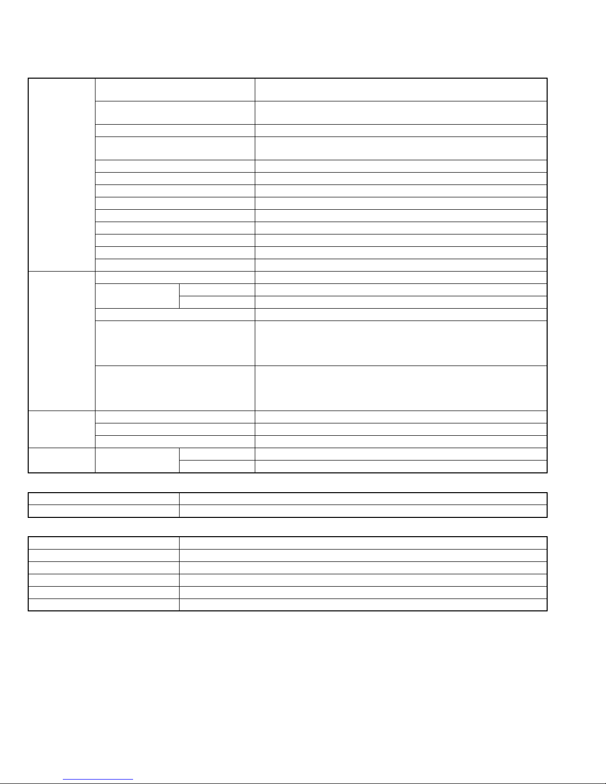
SPECIFICATION
Camcorder
For General Power supply DC 11 V (Using AC Adapter)
DC 7.2 V (Using battery pack)
Power consumption Approx. 2.7 W*
* When the LED light is off and the monitor backlight is set to [STANDARD] mode.
Dimensions (W × H × D) 133 mm × 68 mm × 54 mm
Weight Approx. 315 g (incl. grip belt)
Approx. 360 g (incl. battery and grip belt)
Operating temperature 0°C to 40°C
Operating humidity 35% to 80%
Storage temperature -20°C to 50°C
Pickup 1/6" (800,000 pixels) CCD
Lens F 1.8 to 4.0, f = 2.2 mm to 77 mm, 35:1 power zoom lens
Filter diameter Ø30.5 mm
LCD monitor 2.7" diagonally measured, LCD panel/TFT active matrix system
Speaker Monaural
LED Light Within 1.5 m (recommended shooting distance)
For Video/Audio Format SD-VIDEO
Recording/Playback
format
Signal format PAL standard
Recording mode (video) ULTRA FINE: 720 × 576 pixels, 8.5 Mbps (VBR)
Recording mode (audio) ULTRA FINE: 48 kHz, 384 kbps
For Still image Format JPEG
Image size 1 mode (640 × 480)
Picture quality 2 modes (FINE/STANDARD)
For connectors USB Camera mini USB type A and B, USB 2.0 compliant
Video MPEG-2
Audio Dolby Digital (2 ch)
FINE: 720 × 576 pixels, 5.5 Mbps (VBR)
NORMAL: 720 × 576 pixels, 4.2 Mbps (VBR)
ECONOMY: 352 × 288 pixels, 1.5 Mbps (VBR)
FINE: 48 kHz, 384 kbps
NORMAL: 48 kHz, 256 kbps
ECONOMY: 48 kHz, 128 kbps
Everio dock mini USB type B, USB 2.0 compliant
AC Adapter
Power requirement AC 110 V to 240 V, 50 Hz/60 Hz
Output DC 11 V, 1 A
Remote Control
Power supply DC 3 V
Battery life Approx. 1 year (depending on the frequency of use)
Operating distance Within 5 m
Operating temperature 0°C to 40°C
Dimensions (W × H × D) 42 mm × 14.5 mm × 91 mm
Weight Approx. 30 g (incl. battery)
Design and specifications subject to change without notice.
* GZ-MG330 model does not include the remote control.
1-2 (No.YF227<Rev.001>)
SECTION 1
r
PRECAUTIONS
1.1 SAFTY PRECAUTIONS
Prior to shipment from the factory, JVC products are strictly
inspected to conform with the recognized product safety and
electrical codes of the countries in which they are to be
sold.However,in order to maintain such compliance, it is equally
important to implement the following precautions when a set is
being serviced.
1.1.1 Precautions during Servicing
(1) Locations requiring special caution are denoted by labels
and inscriptions on the cabinet, chassis and certain parts of
the product.When performing service, be sure to read and
comply with these and other cautionary notices appearing
in the operation and service manuals.
(2) Parts identified by the symbol and shaded ( ) parts
are critical for safety.
Replace only with specified part numbers.
NOTE :
Parts in this category also include those specified to
comply with X-ray emission standards for products
using cathode ray tubes and those specified for
compliance with various regulations regarding
spurious radiation emission.
(3) Fuse replacement caution notice.
Caution for continued protection against fire hazard.
Replace only with same type and rated fuse(s) as
specified.
(4) Use specified internal wiring. Note especially:
• Wires covered with PVC tubing
• Double insulated wires
• High voltage leads
(5) Use specified insulating materials for hazardous live parts.
Note especially:
• Insulation Tape
• PVC tubing
•Spacers
• Insulation sheets for transistors
•Barrier
(6) When replacing AC primary side components (transformers,
power cords, noise blocking capacitors, etc.) wrap ends of
wires securely about the terminals before soldering.
emission. Consequently, when servicing these products,
replace the cathode ray tubes and other parts with only the
specified parts. Under no circumstances attempt to modify
these circuits.Unauthorized modification can increase the
high voltage value and cause X-ray emission from the
cathode ray tube.
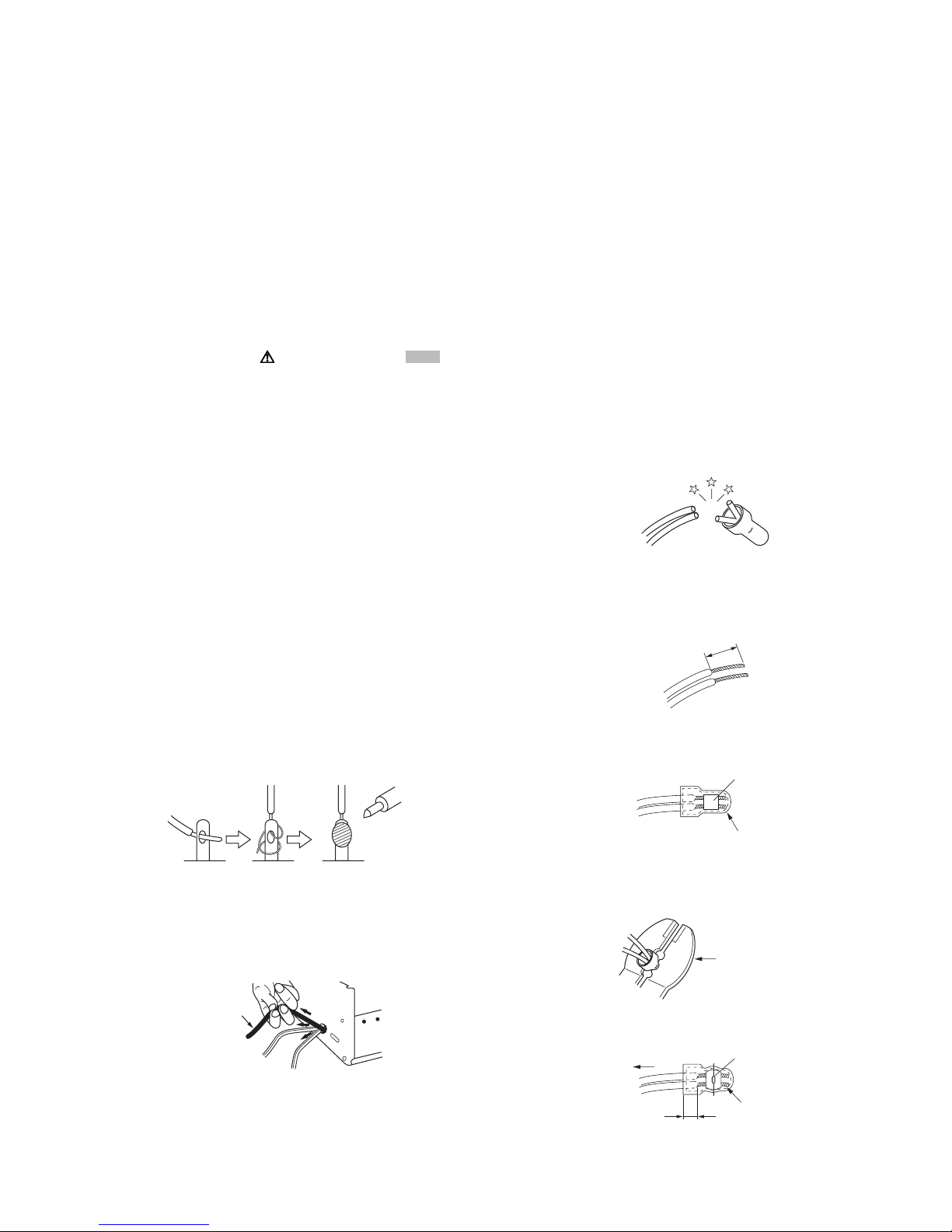
(12) Crimp type wire connectorIn such cases as when replacing
the power transformer in sets where the connections
between the power cord and power trans former primary
lead wires are performed using crimp type connectors, if
replacing the connectors is unavoidable, in order to prevent
safety hazards, perform carefully and precisely according
to the following steps.
• Connector part number :E03830-001
• Required tool : Connector crimping tool of the proper
type which will not damage insulated parts.
• Replacement procedure
a) Remove the old connector by cutting the wires at a
point close to the connector.Important : Do not
reuse a connector (discard it).
cut close to connector
Fig.1-1-3
b) Strip about 15 mm of the insulation from the ends
of the wires. If the wires are stranded, twist the
strands to avoid frayed conductors.
15 mm
Fig.1-1-4
c) Align the lengths of the wires to be connected.
Insert the wires fully into the connector.
Metal sleeve
Fig.1-1-1
(7) Observe that wires do not contact heat producing parts
(heatsinks, oxide metal film resistors, fusible resistors, etc.)
(8) Check that replaced wires do not contact sharp edged or
pointed parts.
(9) When a power cord has been replaced, check that 10-15
kg of force in any direction will not loosen it.
Power cord
Fig.1-1-2
(10) Also check areas surrounding repaired locations.
(11) Products using cathode ray tubes (CRTs)In regard to such
products, the cathode ray tubes themselves, the high
voltage circuits, and related circuits are specified for
compliance with recognized codes pertaining to X-ray
Connector
Fig.1-1-5
d) As shown in Fig.1-1-6, use the crimping tool to crimp
the metal sleeve at the center position. Be sure to
crimp fully to the complete closure of the tool.
1.2
5
2.0
5.5
Crimping tool
Fig.1-1-6
e) Check the four points noted in Fig.1-1-7.
Not easily pulled free
Wire insulation recessed
more than 4 mm
Crimped at approx. cente
of metal sleeve
Conductors extended
Fig.1-1-7
(No.YF227<Rev.001>)1-3
1.1.2 Safety Check after Servicing
Examine the area surrounding the repaired location for damage
or deterioration. Observe that screws, parts and wires have been
returned to original positions, Afterwards, perform the following
tests and confirm the specified values in order to verify
compliance with safety standards.
(1) Insulation resistance test
Confirm the specified insulation resistance or greater
between power cord plug prongs and externally exposed
parts of the set (RF terminals, antenna terminals, video and
audio input and output terminals, microphone jacks,
earphone jacks, etc.).See table 1 below.
(2) Dielectric strength test
Confirm specified dielectric strength or greater between
power cord plug prongs and exposed accessible parts of
the set (RF terminals, antenna terminals, video and audio
input and output terminals, microphone jacks, earphone
jacks, etc.). See Fig.1-1-11 below.
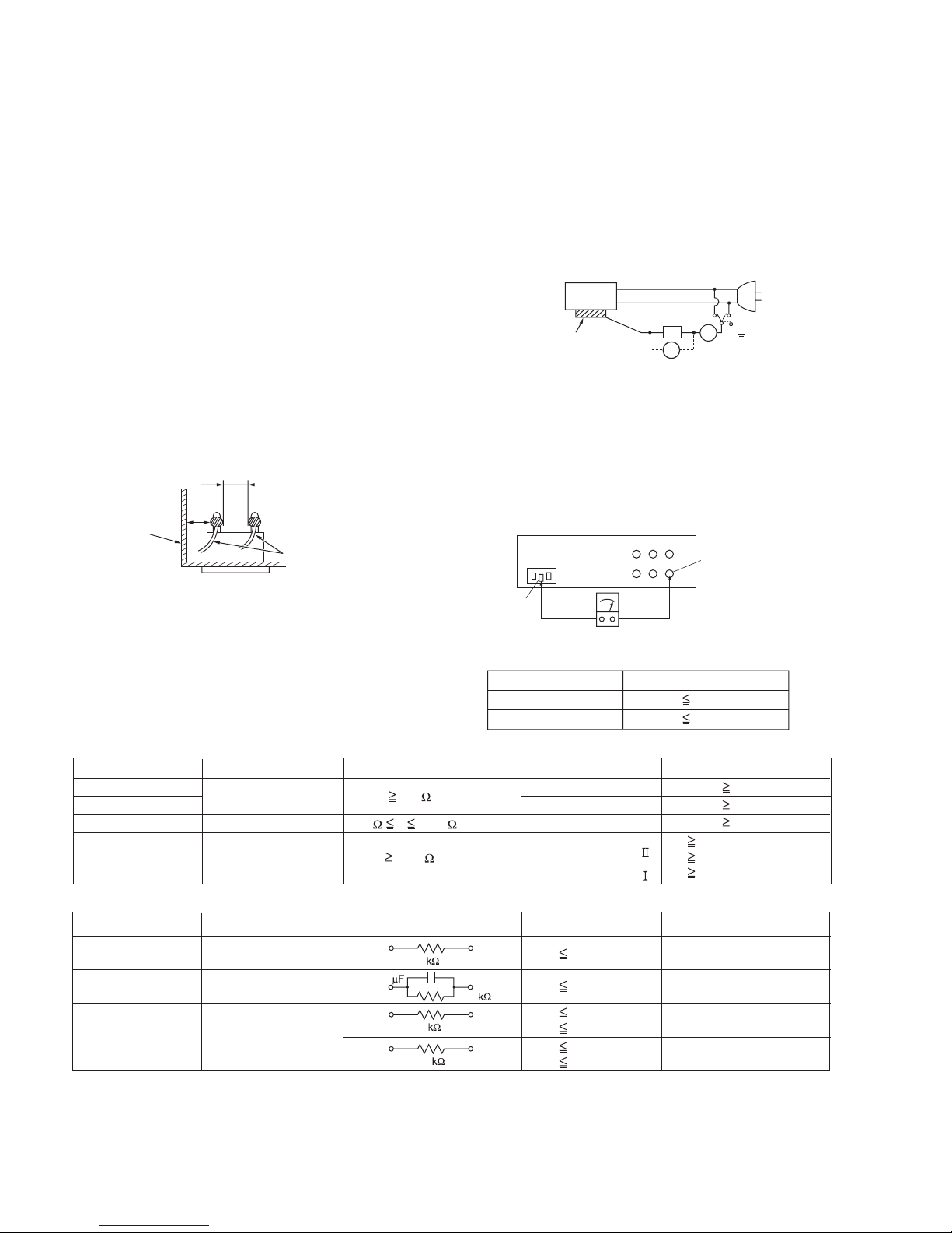
(3) Clearance distance
When replacing primary circuit components, confirm
specified clearance distance (d), (d') between soldered
terminals, and between terminals and surrounding metallic
parts. See Fig.1-1-11 below.
d
Chassis
d'
Power cord
primary wire
Fig.1-1-8
(4) Leakage current test
Confirm specified or lower leakage current between earth
ground/power cord plug prongs and externally exposed
accessible parts (RF terminals, antenna terminals, video
and audio input and output terminals, microphone jacks,
earphone jacks, etc.).
Measuring Method : (Power ON)Insert load Z between
earth ground/power cord plug prongs and externally
exposed accessible parts. Use an AC voltmeter to
measure across both terminals of load Z. See Fig.1-1-9
and following Fig.1-1-12.
ab
Externally
exposed
accessible part
Z
V
c
A
Fig.1-1-9
(5) Grounding (Class 1 model only)
Confirm specified or lower grounding impedance between
earth pin in AC inlet and externally exposed accessible
parts (Video in, Video out, Audio in, Audio out or Fixing
screw etc.).Measuring Method:
Connect milli ohm meter between earth pin in AC inlet and
exposed accessible parts. See Fig.1-1-10 and grounding
specifications.
AC inlet
Earth pin
Exposed accessible part
MIlli ohm meter
Grounding Specifications
Region
USA & Canada
Europe & Australia
Grounding Impedance (Z
Z 0.1 ohm
Z 0.5 ohm
)
Fig.1-1-10
AC Line Voltage
100 V
100 to 240 V
110 to 130 V
110 to 130 V
200 to 240 V
Region
Japan
USA & Canada
Europe & Australia
Insulation Resistance (R
R 1 M /500 V DC
1 M R 12 M /500 V DC
R 10 M /500 V DC
)
Dielectric Strength
AC 1 kV 1 minute
AC 1.5 kV 1 minute
AC 1 kV 1 minute
AC 3 kV 1 minute
AC 1.5 kV 1 minute
(
Class
(
Class
Clearance Distance (d), (d'
d, d' 3 mm
d, d' 4 mm
d, d' 3.2 mm
d 4 m m
)
d' 8 m m (Power cord
d' 6 m m (Primary wire
)
Fig.1-1-11
AC Line Voltage
100 V
110 to 130 V
110 to 130 V
220 to 240 V
Region
Japan
USA & Canada
Europe & Australia
Load Z
1
0.15
1.5
2
50
Leakage Current (i)
i 1 mA rms
i 0.5 mA rms
i 0.7 mA peak
i 2 mA dc
i 0.7 mA peak
i 2 mA dc
a, b, c
Exposed accessible parts
Exposed accessible parts
Antenna earth terminals
Other terminals
Fig.1-1-12
NOTE :
These tables are unofficial and for reference only. Be sure to confirm the precise values for your particular country and locality.
)
)
)
1-4 (No.YF227<Rev.001>)
SECTION 2
SPECIFIC SERVICE INSTRUCTIONS
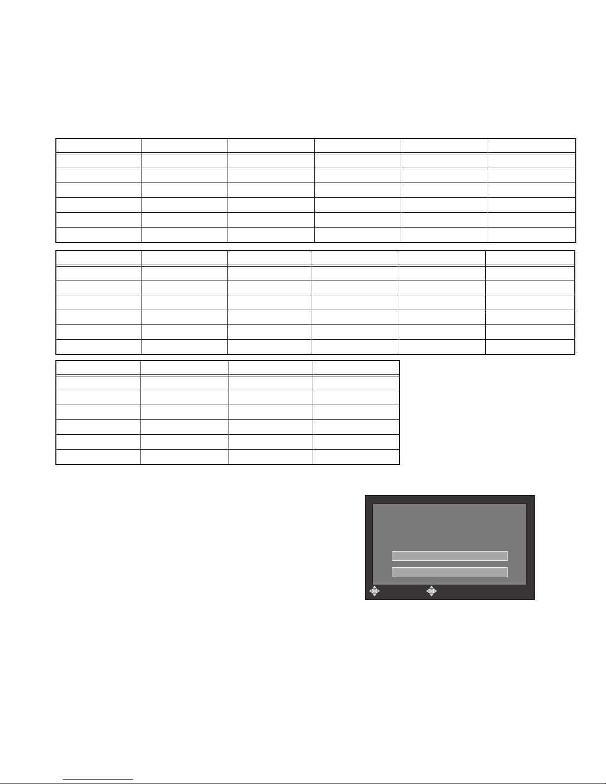
2.1 DIFFERENCE LIST
The following table indicate main different points between models GZ-MG330HEK, GZ-MG330HER, GZ-MG330HEX,
GZ-MG330HEZ, GZ-MG335HEK, GZ-MG335HER, GZ-MG335HEX, GZ-MG335HEZ, GZ-MG340HEX, GZ-MG365HEK,
GZ-MG365HER, GZ-MG365HEX, and GZ-MG365HEZ.
MODEL NAME GZ-MG330HEK GZ-MG330HER GZ-MG330HEX GZ-MG330HEZ GZ-MG335HEK
HDD 30GB 30GB 30GB 30GB 30GB
LED LIGHTNONONONOYES
EVERIO DOCK NO NO NO NO YES(CU-VC4U)
AC-ADAPTER AP-V14E AP-V17E AP-V17E AP-V17E AP-V14E
AC CORD YES(BS) NO NO NO YES(BS)
REMOTE CONTROL UNIT
MODEL NAME GZ-MG335HER GZ-MG335HEX GZ-MG335HEZ GZ-MG340HEX GZ-MG365HEK
HDD 30GB 30GB 30GB 40GB 60GB
LED LIGHT YES YES YES NO YES
EVERIO DOCK YES(CU-VC4U) YES(CU-VC4U) YES(CU-VC4U) NO YES(CU-VC4U)
AC-ADAPTER AP-V17E AP-V17E AP-V17E AP-V17E AP-V14E
AC CORD NO NO NO NO YES(BS)
REMOTE CONTROL UNIT
YES(RM-V751US) YES(RM-V751US) YES(RM-V751US) YES(RM-V751US) YES(RM-V751US)
NO NO NO NO YES(RM-V751US)
MODEL NAME GZ-MG365HER GZ-MG365HEX GZ-MG365HEZ
HDD 60GB 60GB 60GB
LED LIGHT YES YES YES
EVERIO DOCK YES(CU-VC4U) YES(CU-VC4U) YES(CU-VC4U)
AC-ADAPTER AP-V17E AP-V17E AP-V17E
AC CORD NO NO NO
REMOTE CONTROL UNIT
2.2 REPLACING HDD
NOTE1) After HDD replacement, format the HDD first.
When the power is turned on after the HDD replacement, the
below "Warning screen" is displayed.
Be sure to format the HDD following the messages.
Be sure to turn off the power once after the formatting.
If the HDD recording is started without being turned off the
power, normal recording cannot be performed although the recording will start.
NOTE2)
The picture title data needs to be written in the HDD.
Download the data and writing procedure from JS-NET.
Note that the picture title is a thumbnail image used in Creating
Playlist including Titles and saved in the space where users
cannot see.
YES(RM-V751US) YES(RM-V751US) YES(RM-V751US)
< "Warning screen">
0''&61(14/#6*#4&&+5-&4+8'
#..#9+..$''4#5'&
&1;179#0661(14/#6!
㪜㪯㪜㪚㪬㪫㪜
㪚㪘㪥㪚㪜㪣
㪪㪜㪣㪜㪚㪫 㪪㪜㪫
(No.YF227<Rev.001>)1-5

2.3 SERVICE FOR EVERIO DOCK (CU-VD4)
2.3.1 Service repair parts
This unit mainly consists of CABINET PARTS and two BOARD
ASSYS.
The main service repair parts are as follows.
For details of service repair parts, please refer to the parts list.
• CABINET PARTS
• BOARD ASSYS
(CDL JACK BOARD ASSY & CDL CN BOARD ASSY)
• Some electrical parts
2.3.2 Disassembly
1. Removing the TOP CASE (Refer to Fig.2-3-1)
Remove the 4 screws (1-4), and then remove the TOP CASE.
2. Removing the HOLDER (Refer to Fig.2-3-2)
Take out the CDL CN BOARD ASSY from the BOTTOM
CASE.
Pull out the HOLDER from the connector by releasing the 4
hooks holding the HOLDER one by one.
Note) During the procedure, be careful in handling the
SPRING.
3. Removing the SPRING (Refer to Fig.2-3-3)
Release the CDL CN BOARD ASSY as shown in the figure,
and take out the SPRING from the BOTTOM CASE.
4. Removing the CDL CN BOARD ASSY/ CDL JACK BOARD
ASSY (Refer to Fig.2-3-4)
Release the lock of CN2, and remove the CDL CN BOARD
ASSY while pulling out the FPC.
Release one hook, and remove the CDL JACK BOARD ASSY.
1-6 (No.YF227<Rev.001>)
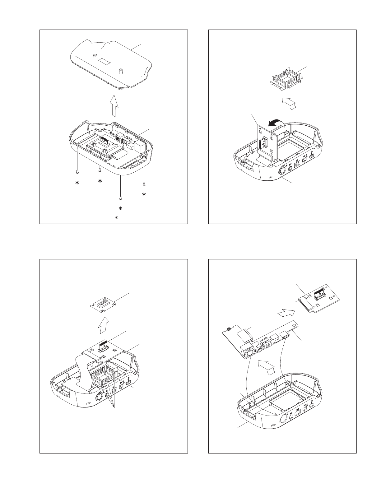
TOP CASE
BOTTOM CASE
SPRING
CDL CN BOARD ASSY
1
3
BOTTOM CASE
2
4
0.069Nm (0.7kgfcm)
Fig.2-3-1
HOLDER
CDL CN BOARD ASSY
BOTTOM CASE
CDL CN BOARD ASSY
FPC
Fig.2-3-3
CN2
CDL JACK BOARD ASSY
HOOK
Fig.2-3-2
SPRING
HOOK
BOTTOM CASE
Fig.2-3-4
(No.YF227<Rev.001>)1-7
SECTION 3
DISASSEMBLY
3.1 BEFORE ASSEMBLY AND DISASSEMBLY
3.1.1 Precautions
• Be sure to disconnect the power supply unit prior to mounting
and soldering of parts.
• Prior to removing a component part that needs to disconnect
its connector(s) and its screw(s), first disconnect the wire(s)
from the connector(s), and then remove the screw(s).
• When connecting/disconnecting wires, pay enough attention
not to damage the connectors.
• When inserting the flat wire to the connector, pay attention to
the direction of the flat wire.
• Be careful in removing the parts to which some spacer or
shield is attached for reinforcement or insulation.
• When replacing chip parts (especially IC parts), first remove
the solder completely to prevent peeling of the pattern.
• Tighten screws properly during the procedures. Unless
otherwise specified, tighten screws at a torque of 0.088N
·cm). However, as this is a required value at the time of
(0.9kgf
production, use the value as a measuring stick when
proceeding repair services. (See "SERVICE NOTE" as for
tightening torque.)
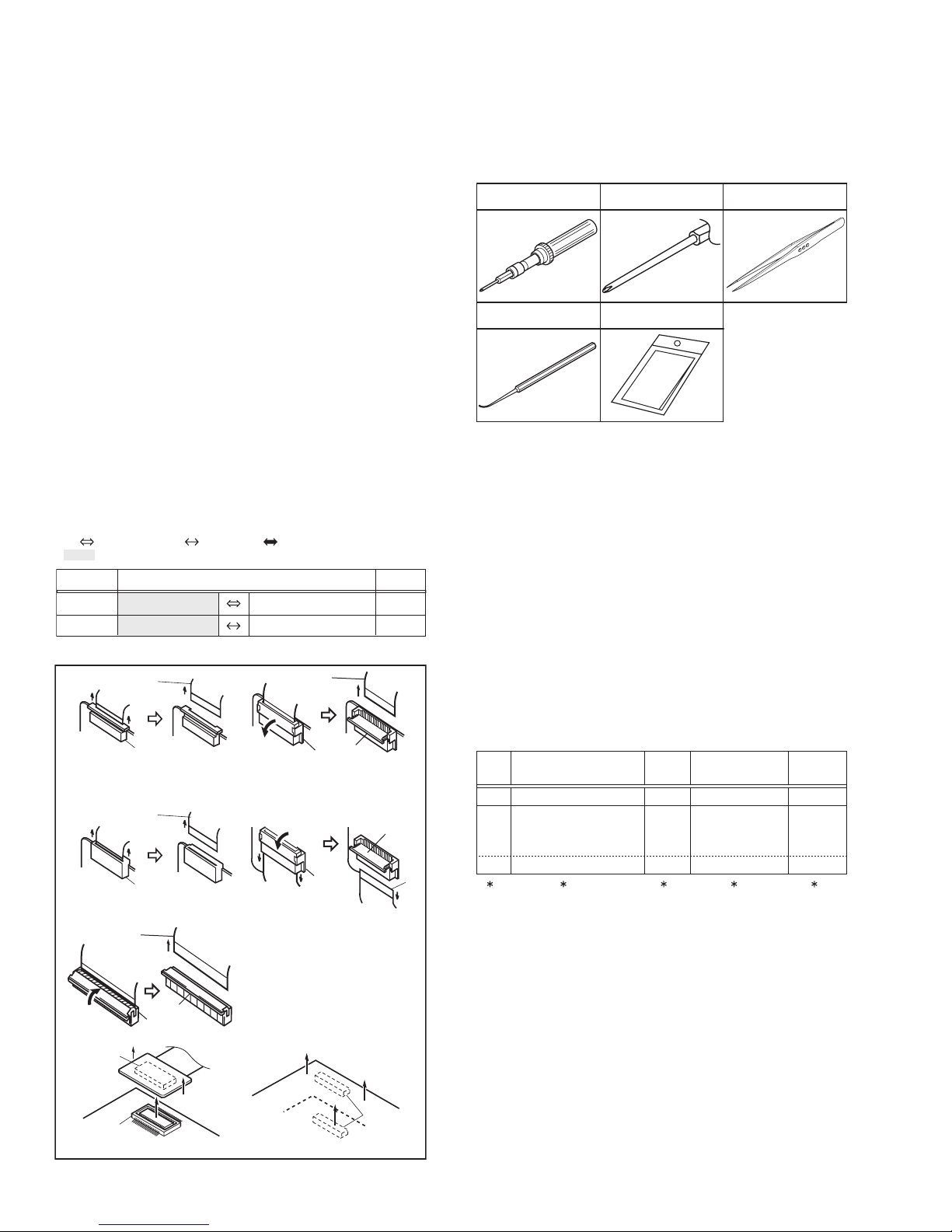
3.1.2 Destination of connectors
Two kinds of double-arrows in connection tables respectively
show kinds of connector/wires.
: Wire: Flat wire : Board to board (B-B)
: The connector of the side to remove
CONN. No. PIN No.CONNECTOR
CN2a
CN2b
MAIN CN101
MAIN CN103
MONI BW CN761
MINI BW CN762
3.1.3 Disconnection of connectors (Wires)
Wire
FPC Connector
· Pull both ends of the connector in the arrow
direction, remove the lock and disconnect the flat
wire.
Wire
FPC Connector
· Pull the both ends of the board in the direction of the
arrow, and remove the Connector.
Wire
Lock
FPC Connector
B-B Connector
B-B Connector
· Pull the both ends of the board in the direction of the arrow, and remove the B-B Connector.
· Extend the locks in the direction of the arrow for
unlocking and then pull out the wire. After
removing the wire, immediately restore the locks
to their original positions because the locks are
apt to come off the connector.
· Extend the locks in the direction of the arrow for
unlocking and then pull out the wire. After
removing the wire, immediately restore the locks
to their original positions because the locks are
apt to come off the connector.
· Extend the locks in the direction of the arrow for
unlocking and then pull out the wire. After
removing the wire, immediately restore the locks
to their original positions because the locks are
apt to come off the connector.
Wire
FPC Connector
FPC
Connector
Lock
B-B Connector
Fig.3-1-1
·m
40
10
Lock
Wire
3.1.4 Tools required for disassembly and assembly
Torque driver
YTU94088
Chip IC replacement jig
PTS40844-2
Bit
YTU94088-003
Cleaning cloth
KSMM-01
Tweezers
P-895
Fig.3-1-2
• Torque driver
Be sure to use to fastening the mechanism and exterior parts
because those parts must strictly be controlled for tightening
torque.
• Bit
This bit is slightly longer than those set in conventional torque
drivers.
• Tweezers
To be used for removing and installing parts and wires.
• Chip IC replacement jig
To be used for replacement of IC.
• Cleaning cloth
Recommended cleaning cloth to wipe down the video heads,
mechanism (tape transport system), optical lens surface.
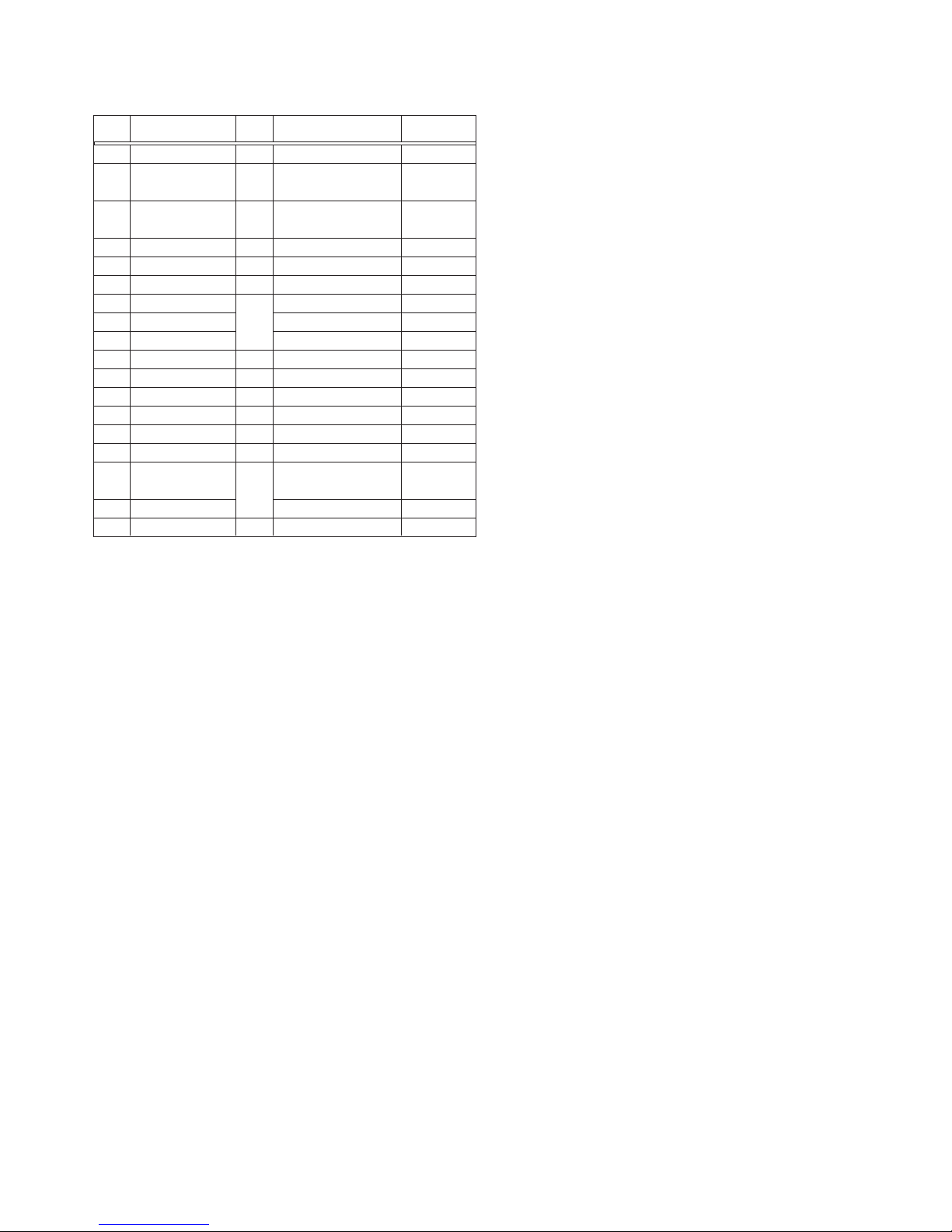
3.2 ASSEMBLY AND DISASSEMBLY OF MAIN PARTS
3.2.1 Assembly and disassembly
When reassembling, perform the step(s) in reverse order.
STEP
No.
[1]
[2]
PART
TOP COVER ASSY
UPPER ASSY
(Inc. VF ASSY,
SPEAKER/MONITOR)
[8]
E.VF UNIT(B/W)
(∗1) Order of steps in Procedure
When reassembling, preform the step(s) in the reverseorder.
These numbers are also used as the identification (location)
No. of parts Figures.
(∗2) Part to be removed or installed.
(∗3) Fig. No. showing Procedure or Part Location.
(∗4) Identification of part to be removed, unhooked, unlocked,
released, unplugged, unclamped or unsoldered.
S = Screw L = Lock, Release, Hook
SD = Solder CN = Connector
[Example]
• 4 (S1a) = Remove 4 S1a screws.
• 3 (L1a) = Disengage 3 L1a hooks.
• 2 (SD1a) = Unsolder 2 SD1a points.
• CN1a = Remove a CN1a connector.
(∗5) Adjustment information for installation.
Fig.
No.
4(S1a), 3(L1a),CN1a
C1
(S2a),2(S2b),3(S2c)
C2-1
2(SD1a),
L2,CN2a,b
2(S8),L8,CN8a
C2-2
POINT
( 4) ( 5)( 2) ( 3)( 1)
NOTE
-
-
NOTE 8
1-8 (No.YF227<Rev.001>)
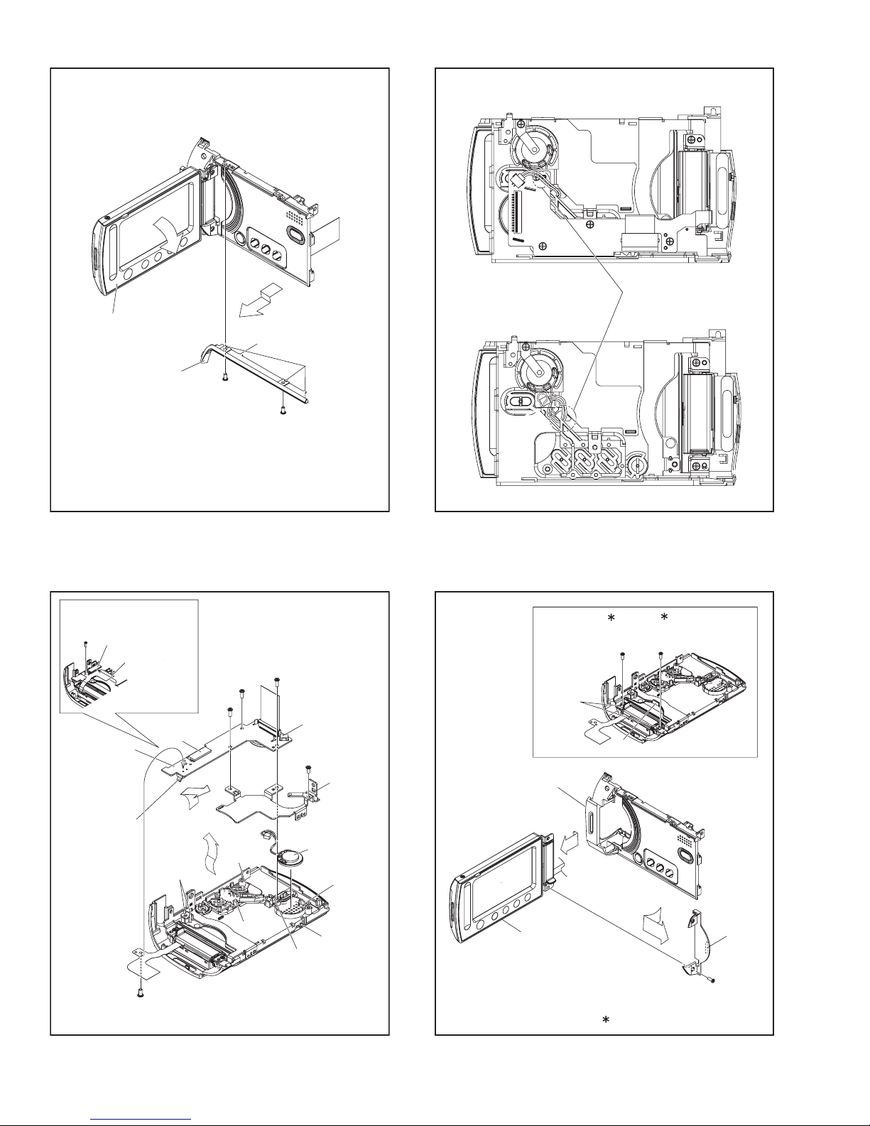
3.2.2 Assembly/Dissambly of cabinet parts and electrical parts
z Disassembly procedure
STEP
PART NAME
No.
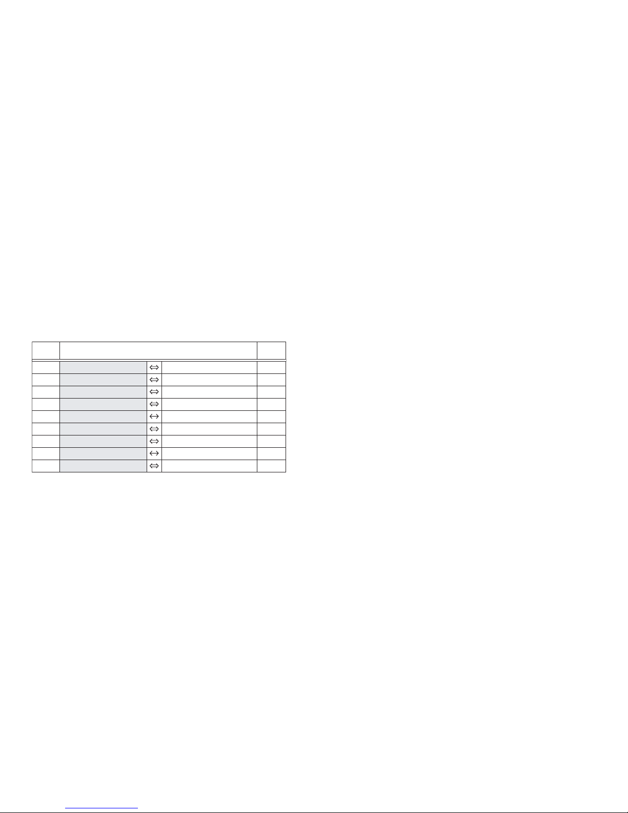
[1]
B.COVER ASSY
[2]
WINDOW(IR)
[3]
TOP COVER ASSY
[4]
HDD COVER ASSY
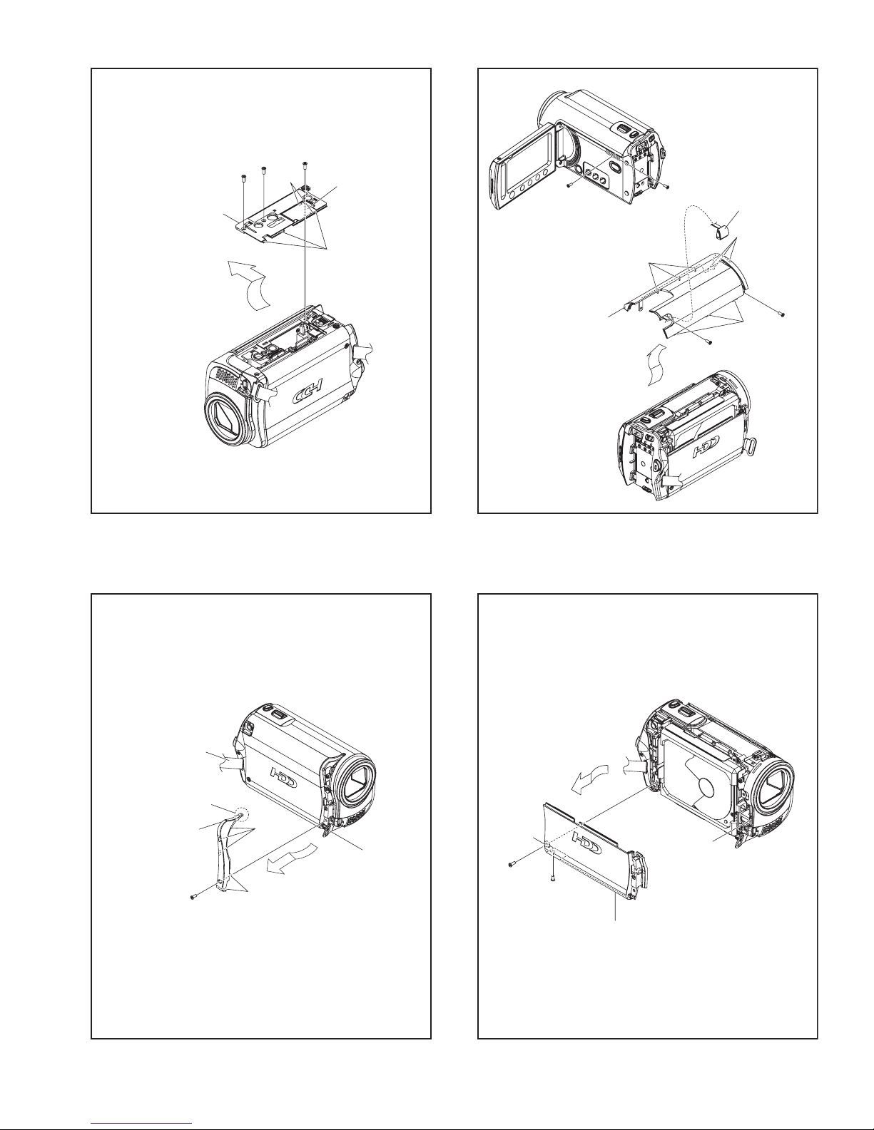
[5]
HDD
[6]
HDD CASE
[7]
REAR COVER ASSY
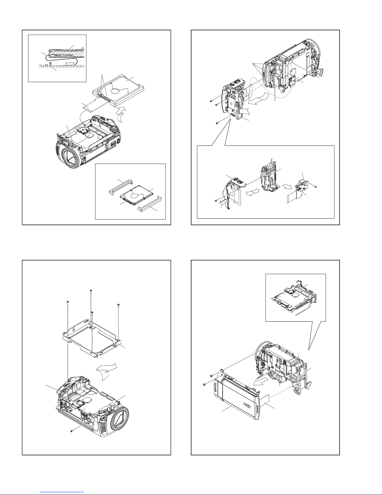
[8]
ZOOM UNIT
[9]
REAR BOARD ASSY
[10]
UPPER ASSY
[11]
FRONT ASSY
[12]
MIC
[13]
MAIN BOARD ASSY
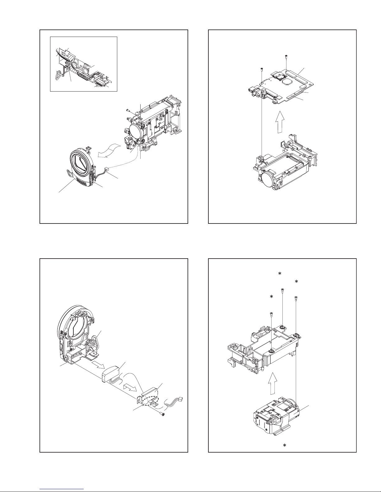
[14]
OP BLOCK ASSY
[15]
ORNAMENT(TOP)
[16]
OPE BOARD ASSY
[17]
SPEAKER
[18]
MONITOR ASSY
Fig.
No.
3-2-1
3-2-2
3-2-3
3-2-4
3-2-5
3-2-6
3-2-7
3-2-8
3-2-9
3-2-10
3-2-11
3-2-12
3-2-13
3-2-14-1
/3-2-14-2
3-2-15
POINT NOTE
3(S1),2(L1a), 3(L1b)
GRIP BELT,
S2,2(L2a),3(L2b),L2c
3(S3),JACK COVER(AV),
S3,3(L3a),3(L3b),3(L3c)
2(S4), L4a,b
CN5
5(S6),L6a,b
CN7a,b,3(S7),L7a,3(L7b)
2(S8), L8
L9a,2(L9b)
CN10, 2(S10), L10a,b
CN11,S11, L11a,b
S12, L12a, L12b, PLATE(MIC)
CN13a,b, 2(S13)
3(S14)
2(S15), L15a, 3(L15b)
CN16a,b, S16, 2(L16a),
2(L16b), 3(S16)
S17, L17a,b, 2(L17c), BKT(SPK)
S18a, L18a, 2(S18b), 2(L18b)
NOTE1
NOTE2a,b
NOTE3
NOTE5a,b,c,d,e,f
NOTE7
NOTE8
NOTE9
NOTE10a,b
NOTE11a,b
NOTE12
NOTE13
NOTE14a,b
NOTE15a,b
NOTE16a,b
NOTE17
NOTE18
-
-
NOTE1:
When removing the BOTTOM COVER ASSY, open and pull
up the COVER (SD).
NOTE2a:
Pull out the GRIP BELT from the hook and leave it released
before removing the HDD COVER ASSY.
NOTE2b:
During the procedure, be careful not to damage the parts.
NOTE3:
When attaching, be careful not to pinch the parts.
NOTE5a:
During the procedure, be careful in handling the parts.
Pay special attention not to give any external shock to the
HDD.
NOTE5b:
When the HDD is replaced, be sure to refer to Replacing
HDD in "SECTION2 SPECIFIC SERVICE INSTRUCTIONS"
for the procedure after HDD replacement.
NOTE5c:
Be careful as the RUBBER SPACERS on both sides are
easily come off when the HDD is removed from the main
unit.
NOTE5d:
When connecting the FPC to the connector, insert the FPC
straight into the connector. When locking the connector, be
careful not to give so much load that it bends the board.
NOTE5e:
In this procedure, the FPC connected to the HDD connector
is not removed.
If the FPC is removed due to broken wire, be careful in attachment direction.
Pay attention as wrong attachment could damage the HDD.
NOTE5f:
Be careful with the wiring.
NOTE7:
When removing the REAR COVER ASSY, remove the
ZOOM UNIT together with the REAR BOARD ASSY.
NOTE8:
When attaching, first adjust the AV jack position, and then
carefully adjust the DC jack position.
NOTE9:
During the procedure, be careful not to touch or damage the
battery terminal.
NOTE10a:
When removing, release the connector lock, and then pull
out the FPC together with the UPPER ASSY.
NOTE10b:
Please refer to Fig.3-2-13 and the following procedure for removing the UPPER ASSY.
NOTE11a:
When attaching, be careful in handling the JACK COVER
(USB) ASSY.
NOTE11b:
When attaching, be careful with the wiring (MIC).
NOTE12:
When attaching, be careful with the wiring (MIC).
(No.YF227<Rev.001>)1-9
NOTE13:
Be careful with the wiring.
NOTE14a:
During the procedure, be careful in handling the parts.
NOTE14b:
Refer to 3.2.3
CCD BOARD ASSY
Assembly/Disambly of [14] OP BLOCK ASSY/
.
NOTE15a:
During the procedure, turn the MONITOR ASSY 90°, so that
it does not interfere with the procedure.
NOTE15b:
During the procedure, be careful not to damage the parts.
NOTE16a:
When removing, remove the screw No.32 first to release the
FPC, and then pull out the FPC from the connector.
NOTE16b:
When attaching, be careful with the wiring.
NOTE17:
When attaching, be careful with the wiring.
NOTE18:
Refer to 3.2.4 Disassembly of [18] MONITOR ASSY.
z Destination of connectors
CN.
No.
CONNECTOR
PIN
No.
CN5 MAIN CN102 HDD - 40
CN7a MAIN CN104 ZOOM UNIT - 12
CN7b MAIN CN103 REAR
CN601 32
CN10 MAIN CN101 OPE CN401 30
CN11 MAIN CN107 MIC - 4
CN13a MAIN CN105 CCD CN5001 22
CN13b MAIN CN106 OP BLOCK - 25
CN16a OPE CN403 SPEAKER - 2
CN16b OPE CN402 MONITOR CN7601 22/23
1-10 (No.YF227<Rev.001>)
[1]
1
(S1)
2
(S1)
L1a
3
(S1)
COVER(SD)
NOTE1
L1b
6
(S3)
L3c
5
(S3)
JACK COVER(AV)
L3b
NOTE3
Fig.3-2-1
[3]
Fig.3-2-3
8
(S3)
L3a
7
(S3)
NOTE2a
GRIP BELT
NOTE2a
L2c
[2]
4
(S2)
L2b
L2a
Fig.3-2-2
HOOK
10
(S4)
L4a
L4b
9
(S4)
[4]
Fig.3-2-4
(No.YF227<Rev.001>)1-11
NOTE5f
FPC
HDD
MAIN PWB
<CROSS SECTION>
NOTE5e
FPC
NOTE5d
CN5
STOPPER
NOTE5c
RUBBER SPACER
CONNECTOR
Fig.3-2-5
NOTE5a,b
[5]
SHIELD
(HDD)
RUBBER SPACER
17
(S7)
16
(S7)
18
(S7)
NOTE8
20
(S8)
[8]
L7b
[7]
NOTE7
L9b
Fig.3-2-7
L7a
L9a
CN7a
CN7b
NOTE9
[9]
19
(S8)
L8
L6b
14
(S6)
11
(S6)
12
(S6)
13
(S6)
Fig.3-2-6
15
(S6)
[6]
L6a
21
(S10)
22
(S10)
[10]
NOTE10b
CN10
L10b
NOTE10a
CN10
L10a
FPC
Fig.3-2-8
1-12 (No.YF227<Rev.001>)
L11b
WIRE(MIC)
NOTE11b
[11]
JACK COVER(USB) ASSY
NOTE11a
23
(S11)
CN11
WIRE(MIC)
NOTE11b
L11a
L11b
25
(S13)
26
(S13)
NOTE13
[13]
CN13a
CN13b
L12a
Fig.3-2-9
L12b
NOTE12
[12]
PLATE(MIC)
24
(S12)
Fig.3-2-11
27
(S14)
28
(S14)
29
(S14)
NOTE14a,b
[14]
Fig.3-2-10
0.118Nm (1.2kgfcm)
Fig.3-2-12
(No.YF227<Rev.001>)1-13
NOTE16b
WIRE(SPEAKER)
MONITOR ASSY
NOTE15a
NOTE15b
32
(S16)
OPE PWB
NOTE16a
CN16b
FPC
(MONITOR)
ASSY
[15]
Fig.3-2-13
CN16b
30
(S15)
35
(S16)
33
(S16)
L15a
31
(S15)
34
(S16)
L15b
NOTE16b
CN16a
36
(S17)
BKT(SPK)
NOTE17
Fig.3-2-14-2
L18b
UPPER CASE ASSY
38
(S18b)
L18a
39
(S18b)
[16]
(LCD_OPEN)
1-14 (No.YF227<Rev.001>)
SW
L16b
L16a
L17a
L16b,L17c
32
(S16)
Fig.3-2-14-1
NOTE17
[17]
L17c
L17b
[18]
NOTE18
L18a
37
(S18a)
0.196Nm (2.0kgfcm)
Fig.3-2-15
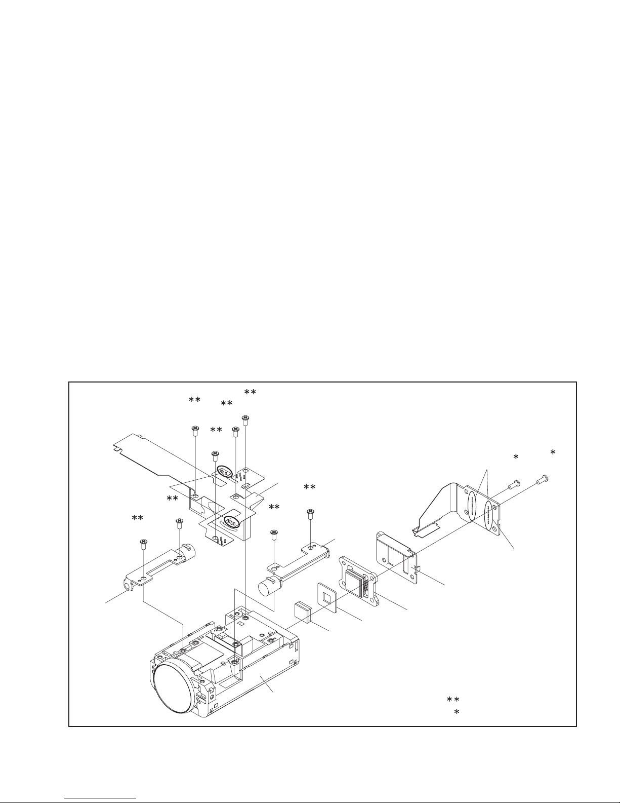
3.2.3 Assembly/Disambly of [14] OP BLOCK ASSY/CCD BOARD ASSY
zPrecautions
(1) Be careful in handling the CCD IMAGE SENSOR, OPTI-
CAL LPF and the LENS components.
Pay special attention to the surfaces to protect them from
stains, dust, or scratches.
If the surfaces are soiled with finger prints or other stains,
wipe them off with silicon paper, clean chamois leather,
or recommended cleaning cloth.
(2) The CCD IMAGE SENSOR may have been shipped with
a protective sheet attached to the transmitting glass.
When replacing the CCD IMAGE SENSOR, do not peel
off this sheet from the new part until immediately before
it is mounted in the OP BLOCK ASSY.
zDisassembly of OP BLOCK ASSY / CCD BOARD ASSY
(1) Unsolder the 20 soldered points (SD14a) of the CCD
BOARD ASSY.
(2) Remove the 2 screws (1,2), and then remove the CCD
BOARD ASSY,SHIELD(CCD) and the CCD BASE ASSY.
NOTE14a:
When removing the CCD BASE ASSY, be careful in
handling as the CCD IMAGE SENSOR may be removed together with the SHEET and the OP LPF attached.
(3) Remove the SHEET and OP LPF.
zAssembly of OP BLOCK ASSY / CCD BOARD ASSY
(1) Set the OP LPF first, and then the SHEET to the OP
(2) Attach the CCD BASE ASSY first, then the SHEET,
(3) Solder the 20 points (SD14a) on the CCD BOARD AS-
zReplacement of service repair parts
The service repair parts for the OP BLOCK ASSY are as listed
below.
When replacing parts, be careful not to cut the FPCs or damage any parts by soldering (excessive heat).
(1) FOCUS MOTOR UNIT
(2) ZOOM MOTOR UNIT
(3) AUTO IRIS UNIT
NOTE 14d:
The IRIS MOTOR UNIT includes the FPC ASSY and two
sensors.
NOTE14b:
Replace the CCD IMAGE SENSOR as a CCD BASE
ASSY, not as a single part replacement.
BLOCK ASSY.
NOTE14c:
Be careful with the attachment direction of the OP
LPF.
SHIELD(CCD) and the CCD BOARD ASSY so that the
SHEET stays in place, and then tighten with the 2 screws
(1,2).
SY.
(S14b)
ZOOM MOTOR
UNIT
SD14b
5
6
(S14b)
10
(S14b)
(S14b)
7
(S14b)
9
8
(S14b)
NOTE14d
AUTO IRIS UNIT
3
(S14b)
4
(S14b)
FOCUS MOTOR
UNIT
SHEET
OP LPF
NOTE14a,c
SD14a
CCD BOARD ASSY
SHIELD(CCD)
NOTE14a,b
CCD BASE ASSY
1
(S14a)
2
(S14a)
OP BLOCK ASSY
Fig.3-2-16
0.078Nm (0.8kgfcm)
0.147Nm (1.5kgfcm)
(No.YF227<Rev.001>)1-15
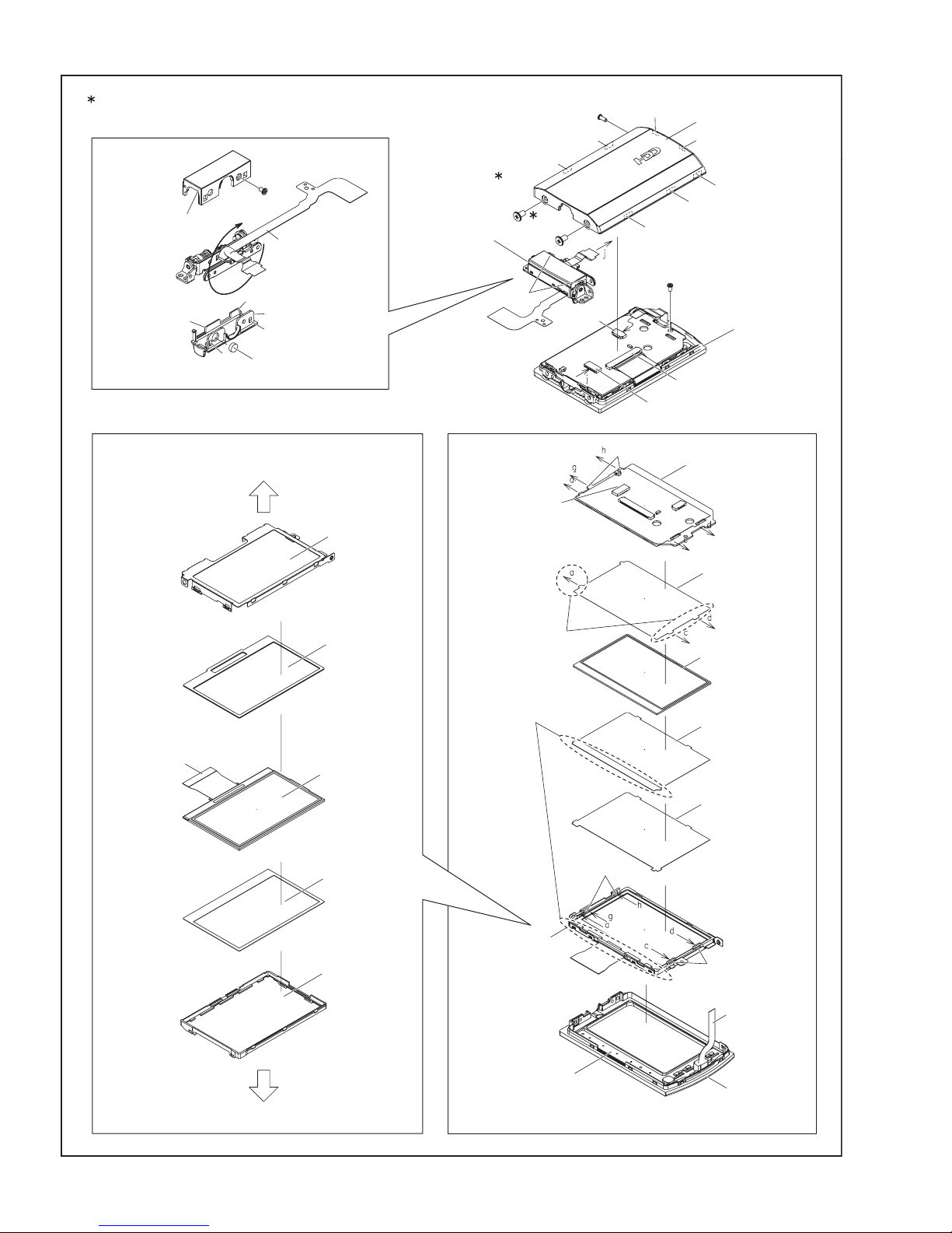
3.2.4 Disassembly of [18] MONITOR ASSY
zCAUTIONS
(1) During the procedure, be careful in handling the LCD
MODULE and other parts. Pay special attention not to
damage or stain the monitor screen.
If fingerprints are left on the screen, wipe them with clean
chamois leather or a cleaning cloth.
z Removing MONITOR ASSY
(1) Remove the screw (1).
(2) Turn the HINGE UNIT ASSY 90°, and remove the 2
screws (2,3).
(3) Remove the MONI.COVER ASSY by removing the 7
hooks (L18a-g).
(4) Release the lock of the connector (CN18a), and remove
the HINGE UNIT by lifting it up.
NOTE18a:
During the procedure, be careful in handling the FPC.
(5) Release the lock of the connectors (CN18b,c), and pull
out the FPC.
(6) Remove the screw (4), and remove the MONITOR
BOARD ASSY .
NOTE18b:
During the procedure, be careful in handling the FPC.
(7) Remove the SHEET (M.REF), LIGHT GUIDE,
SHEET(M/DIFF), and the SHEET(BEF).
NOTE18c:
When attaching, insert one side of the SHEET (M/
DIFF) under the LCD CASE RIB.
NOTE18d:
When attaching, insert each tab on both sides of the
SHEET (M.REF) into the LCD CASE notch.
(8) Remove the LCD CASE, SPACER(LCD), LCD MOD-
ULE, SPACER(LCD) and the LCD BKT ASSY.
NOTE18e:
During the procedure, handle the five parts (LCD
CASE, SPACER(LCD), LCD MODULE, SPACER(LCD) and the LCD BKT ASSY) together.
NOTE18f:
The SENSOR BOARD ASSY is originally affixed to the
MONI.CASE ASSY using jigs and they have structures difficult to replace.
If replacement is required, please refer to the NOTE
and follow the operation procedure.
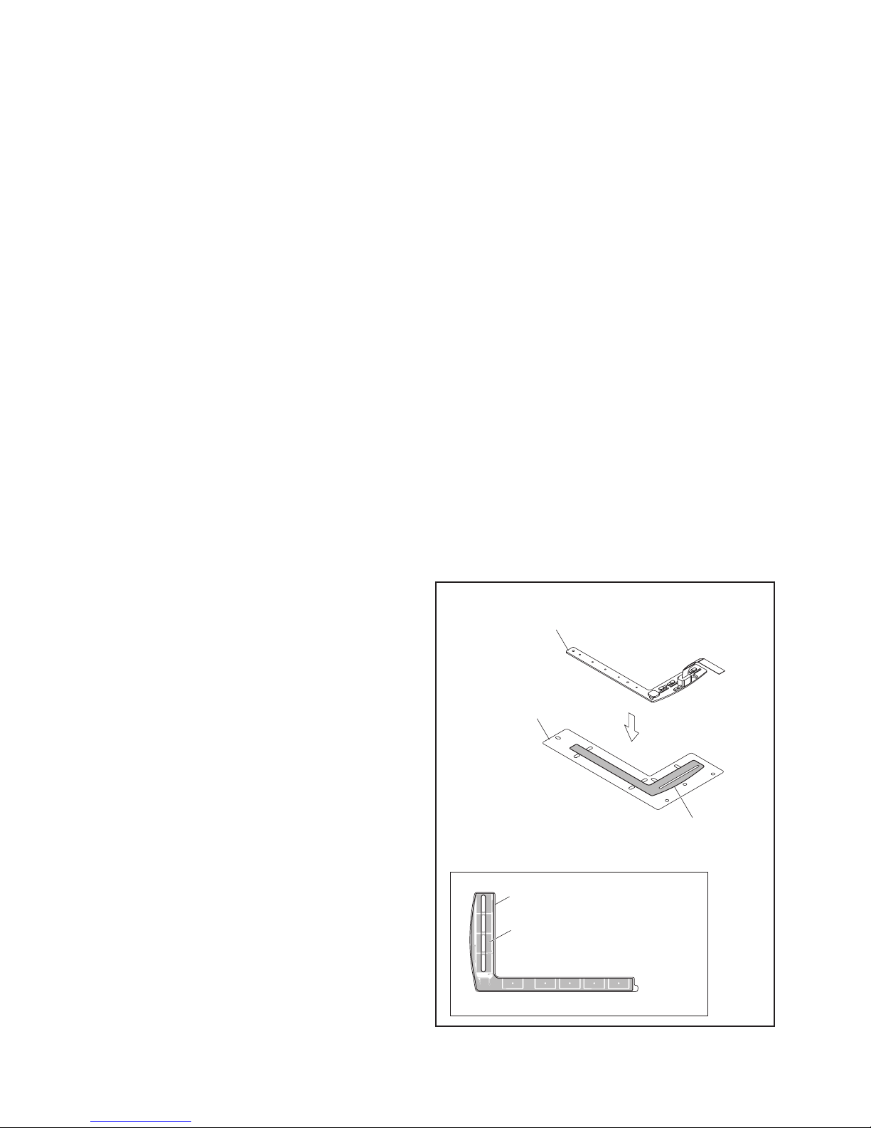
Assembly/Disambly of MONITOR ASSY/SENSOR BOARD ASSY
z
Operation procedure
• Removing the part which is to be reused
(1) Remove the SENSOR BOARD ASSY from the MO-
NI.CASE ASSY by gradually peeling off from the HINGE
ASSY side.
NOTE18g:
During the procedure, be careful not to break or deform the parts or warp the SENSOR BOARD.
(2) Completely peel off the remaining tape pieces of the D.
FACE TAPE left on the part to be reused (MONI.CASE
ASSY or SENSOR BOARD ASSY).
NOTE18h:
Make sure that there are no D. FACE TAPE pieces or
foreign substances left on the surfaces. If necessary,
clean the surfaces using alcohol etc.
• Affixing the D. FACE TAPE to the SENSOR BOARD
(1) Affix the D. FACE TAPE to the SENSOR BOARD ASSY.
NOTE18j:
Securely fix the D. FACE TAPE, and then affix the
SENSOR BOARD ASSY to the D. FACE TAPE by adjusting the four frames of the SENSOR BOARD ASSY
to the frame of the D. FACE TAPE. Evenly press over
the paper backing of each long / short side of the L
shape.
(2) Peel off the paper backing.
NOTE18k:
When removing the paper backing, check that there
are no foreign substances or air bubbles on the tape.
If there are foreign substances etc., completely remove them and continue the affixing procedure.
• Affixing the SENSOR BOARD ASSY to the MONI. CASE
(1) Affix the SENSOR BOARD ASSY to the MONI. CASE
NOTE18m:
When affixing, adjust the position of the long side of
the L shape to avoid misalignment, and then press
evenly.
Be sure to press hard for 10 seconds or more on each
long/ short side of the L shape for even adhesion.
During the procedure, be careful to prevent foreign
substances or air bubbles from entering.
(2) After the replacement, make sure that there are no bro-
ken or deformed parts or any abnormalities.
Use the service software for the operation check of the
touch sensor sensitivity.
NOTE18g,j,k
SENSOR BOARD ASSY
NOTE18j,k
D.FACE TAPE
DETACHMENT PAPER
NOTE18j,k
SENSOR BOARD ASSY
D.FACE TAPE
Fig.3-2-17
1-16 (No.YF227<Rev.001>)

zRemoving HINGE UNIT ASSY
(1) Remove the screw (5), and remove the HINGE COV-
ER(U).
(2) Remove the HINGE COVER(L).
(3) Remove the MAGNET.
NOTE18n:
During the procedure, be careful in handling the FPC.
During the procedure, be careful in handling the MAGNET.
When attaching, set the N pole outside as shown in
the figure. Be careful when removing as there is no
marking.
NOTE18p:
During the procedure, be careful in handling the FPC.
NOTE18q:
The FPC, with its connection to the MONITOR
BOARD ASSY facing inward, is rolled around the axis
(shaft) of the HINGE UNIT ASSY rotation 2.5 rounds
(2.5times).
(No.YF227<Rev.001>)1-17
0.118 Nm (1.2kgfcm)
HINGE COVER(U)
L18m
L18k
L18n
5
(S18b)
FPC
NOTE18p,q
HINGE COVER(L)
L18p
MAGNET
NOTE18n
(S18b)
NOTE18a
HINGE UNIT
ASSY
2
L18h
L18a
3
(S18b)
1
(S18a)
L18b
CN18c
L18f
MONI COVER ASSY
L18g
L18d
L18c
4
(S18a)
MONI CASE ASSY
CN18b
CN18a
L18e
NOTE18e
(REINFORCED SIDE)
<MONI CASE SIDE>
LCD BKT ASSY
SPACER(LCD)
LCD MODULE
SPACER(LCD)
CN18b
NOTE18d
NOTE18c
L18j
MONITOR
ASSYBOARD
SHEET(M.REF)
LIGHT GUIDE
SHEET(M/DIFF)
SHEET(BEF)1
NOTE18d
LCD CASE
<MONI COVER SIDE>
1-18 (No.YF227<Rev.001>)
Fig.3-2-18
LCD CASE RIB
NOTE18c
BOARDSENSOR
ASSY
NOTE18g,h,j
NOTE18d
NOTE18b
MONI CASE ASSY
NOTE18h,j
SECTION 4
ADJUSTMENT
4.1 PREPARATION
4.1.1 Precaution
Camera system and deck system of this model are specially
adjusted by using PC.
However, if parts such as the following are replaced, an
adjustment is required. The adjustment must be performed in a
Service Center equipped with the concerned facilities.
• EEP ROM (IC1005 of MAIN board)
• OP BLOCK ASSEMBLY
• MONITOR ASSEMBLY
In the event of malfunction with electrical circuits, first find a
defective portion with the aid of proper test instruments as shown
in the following electrical adjustment procedure, and then
commence necessary repair/ replacement/adjustment.
• In observing chip TP, use IC clips, etc. to avoid any stress.
Prior to replacement of chip parts (especially IC), remove the
solder completely to prevent peeling of the pattern.
• Use a patch cord if necessary. As for a patch cord, see the
BOARD INTERCONNECTIONS.
• Since connectors are fragile, carefully handle them in
disconnecting and connecting the FPC.
4.1.2 Required test equipment
• Personal computer (for Windows)
• Color TV monitor
• Oscilloscope (dual-trace type, observable 100MHz or higher
frequency). The one observable 300 MHz or higher frequency
is recommended.
• Digital voltmeter
• DC power supply or AC adapter
• Frequency counter (with threshold level adjuster)
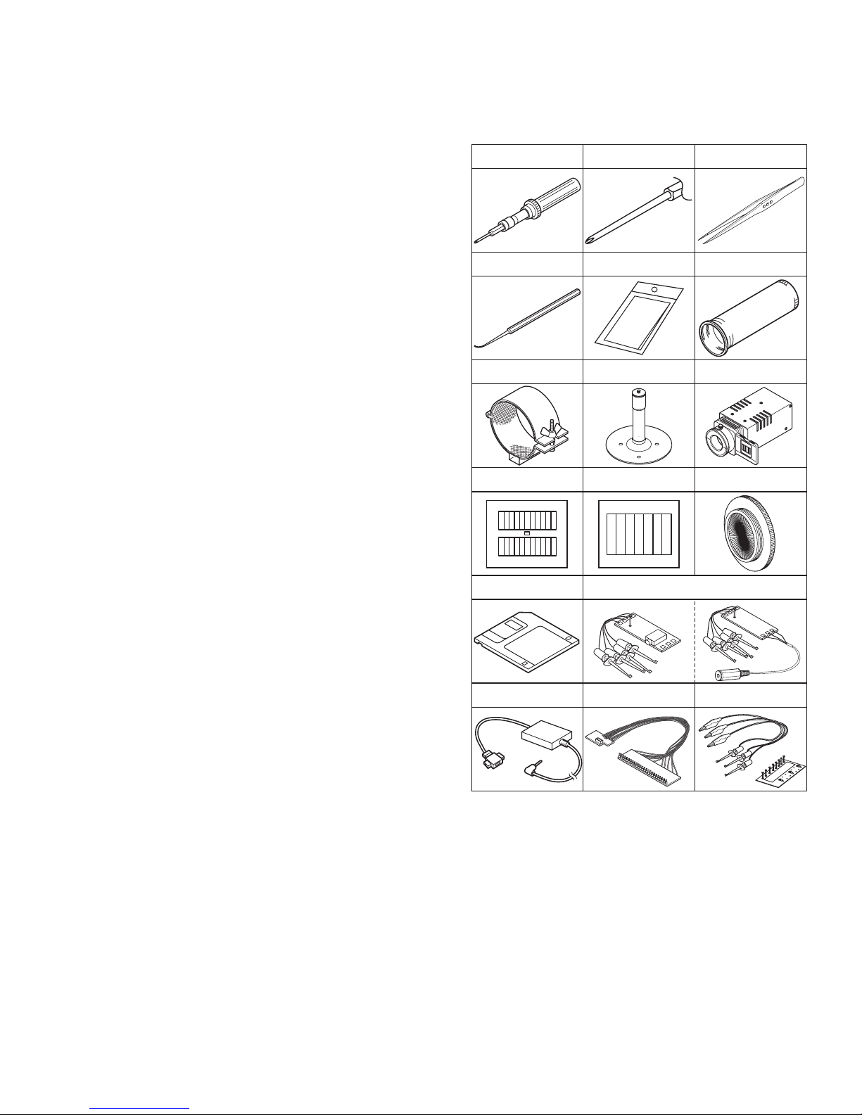
4.1.3 Tools required for adjustment
Torque Driver
YTU94088
Chip IC Replacement Jig
PTS40844-2
INF Adjustment Lens Holder
YTU94087
Gray Scale Chart
YTU94133A
Service Support System
YTU94057-109
Bit
YTU94088-003
Cleaning Cloth
KSMM-01
Mini Stand
YTU93108
Color Bar Chart
YTU94133C
Communication Cable
YTU93111-1
Tweezers
P-895
INF Adjustment Lens
YTU92001B
Light Box Assembly
YTU93096B
Focus Chart
YTU92001-018
PC Cable
QAM0099-005
Jig Connector Cable
YTU93106D
Charing Battery Adjuatment Jig
YTU93112A
• Torque Driver
Be sure to use to fastening the mechanism and exterior parts
because those parts must strictly be controlled for tightening
torque.
• Bit
This bit is slightly longer than those set in conventional torque
drivers.
• Tweezers
To be used for removing and installing parts and wires.
• Chip IC Replacement Jig
To be used for adjustment of the camera system.
• Cleaning Cloth
Recommended the Cleaning cloth to wipe down the video
heads, mechanism (tape transport system), optical lens surface.
(No.YF227<Rev.001>)1-19
 Loading...