

Page 1
SERVICE MANUAL
HD HARD DISK CAMERA
YF289<Rev.003>20096SERVICE MANUAL
GZ-HD300AUS, GZ-HD300BUS,
GZ-HD300RUS, GZ-HD310BUC,
GZ-HD320BUS
GZ-HD300AUSM, GZ-HD300BUSM, GZ-HD300RUSM[M9H413]
GZ-HD310BUCM[M9H415]
GZ-HD320BUSM [M9H417]
COPYRIGHT © 2009 Victor Company of Japan, Limited
Lead free solder used in the board (material : Sn-Ag-Cu, melting point : 219 Centigrade)
TABLE OF CONTENTS
1 PRECAUTIONS . . . . . . . . . . . . . . . . . . . . . . . . . . . . . . . . . . . . . . . . . . . . . . . . . . . . . . . . . . . . . . . . . . . . . . . 1-3
2 SPECIFIC SERVICE INSTRUCTIONS . . . . . . . . . . . . . . . . . . . . . . . . . . . . . . . . . . . . . . . . . . . . . . . . . . . . . . 1-5
3 DISASSEMBLY . . . . . . . . . . . . . . . . . . . . . . . . . . . . . . . . . . . . . . . . . . . . . . . . . . . . . . . . . . . . . . . . . . . . . . . 1-9
4 ADJUSTMENT . . . . . . . . . . . . . . . . . . . . . . . . . . . . . . . . . . . . . . . . . . . . . . . . . . . . . . . . . . . . . . . . . . . . . . . 1-20
5 TROUBLE SHOOTING. . . . . . . . . . . . . . . . . . . . . . . . . . . . . . . . . . . . . . . . . . . . . . . . . . . . . . . . . . . . . . . . . 1-24
COPYRIGHT © 2009 Victor Company of Japan, Limited
No.YF289<Rev.003>
2009/7
Page 2
SPECIFICATION
General Power supply DC 11 V (Using AC adapter)
DC 7.2 V (Using battery pack)
Power consumption Approx. 3.5W*
* When the LED light is off and the monitor backlight is set to [STANDARD]
mode.
Rated Current Consumption: 1A
Dimensions (W × H × D) 53 mm × 68 mm × 113 mm (2-1/8" × 2-11/16" × 4-1/2")
Weight Approx. 325 g (0.7 lbs)
Approx. 370 g (0.8 lbs) (incl. battery pack)
Operating temperature 0°C to 40°C (32°F to 104°F)
Storage temperature -20°C to 50°C (-4°F to 122°F)
Operating humidity 35% to 80%
Camera/LCD
monitor
Connectors AV output Video output 1.0 V (p-p), 75 Ω
AC Adapter Power requirement AC 110 V to 240, 50 Hz/60 Hz
Remote Control Power supply DC 3 V
Still image Format JPEG
Video Signal format 1080/60i
Pickup 1/4.1" (3,050,000 pixels) progressive CMOS
Lens F 1.9 to 3.2, f = 2.9 mm to 58.0 mm, 20:1power zoom lens
Filter diameter Ø30.5 mm
LCD monitor 2.7" diagonally measured, LCD panel/TFT active matrix system
LED Light Within 1.5 m (4.9 ft) (recommended shooting distance)
Audio output 300 mV (rms), 1 kΩ
HDMI HDMI
Component output Y, Pb, Pr component output
USB Mini USB type A and type B,USB 2.0 compliant
Output DC 11 V, 1 A
Battery life Approx. 1 year (depending on the frequency of use)
Operating distance Within 5 m (16.4 ft)
Operating temperature 0°C to 40°C (32°F to 104°F)
Dimensions (W × H × D) 42 mm × 14.5 mm × 91 mm (1-11/16" × 5/8" × 3-5/8")
Weight Approx. 30 g (0.07 lbs) (incl. battery)
Image size 1920 × 1080, 1440 × 1080, 640 × 480
Image quality FINE/STANDARD
Recording/Playback
format
Recording mode (video) UXP: VBR, avarage of 24 Mbps
Recording mode (audio) 48 kHz, 256 kbps
Video MPEG-4 AVC/H.264
Audio Dolby Digital (2ch)
TM
(V.1.3 with x.v.ColorTM)
Y:1.0V (p-p), 75 Ω
Pb/Pr:700 mV (p-p), 75 Ω
XP: VBR, avarage of 17 Mbps
SP: VBR, avarage of 12 Mbps
EP: VBR, avarage of 5 Mbps
Design and specifications subject to change without notice.
1-2 (No.YF289<Rev.003>)
Page 3
SECTION 1
r
PRECAUTIONS
1.1 SAFETY PRECAUTIONS
Prior to shipment from the factory, JVC products are strictly
inspected to conform with the recognized product safety and
electrical codes of the countries in which they are to be
sold.However,in order to maintain such compliance, it is equally
important to implement the following precautions when a set is
being serviced.
1.1.1 Precautions during Servicing
(1) Locations requiring special caution are denoted by labels
and inscriptions on the cabinet, chassis and certain parts of
the product.When performing service, be sure to read and
comply with these and other cautionary notices appearing
in the operation and service manuals.
(2) Parts identified by the symbol and shaded ( ) parts
are critical for safety.
Replace only with specified part numbers.
NOTE :
Parts in this category also include those specified to
comply with X-ray emission standards for products
using cathode ray tubes and those specified for
compliance with various regulations regarding
spurious radiation emission.
(3) Fuse replacement caution notice.
Caution for continued protection against fire hazard.
Replace only with same type and rated fuse(s) as
specified.
(4) Use specified internal wiring. Note especially:
• Wires covered with PVC tubing
• Double insulated wires
• High voltage leads
(5) Use specified insulating materials for hazardous live parts.
Note especially:
• Insulation Tape
• PVC tubing
•Spacers
• Insulation sheets for transistors
• Barrier
(6) When replacing AC primary side components (transformers,
power cords, noise blocking capacitors, etc.) wrap ends of
wires securely about the terminals before soldering.
emission. Consequently, when servicing these products,
replace the cathode ray tubes and other parts with only the
specified parts. Under no circumstances attempt to modify
these circuits.Unauthorized modification can increase the
high voltage value and cause X-ray emission from the
cathode ray tube.
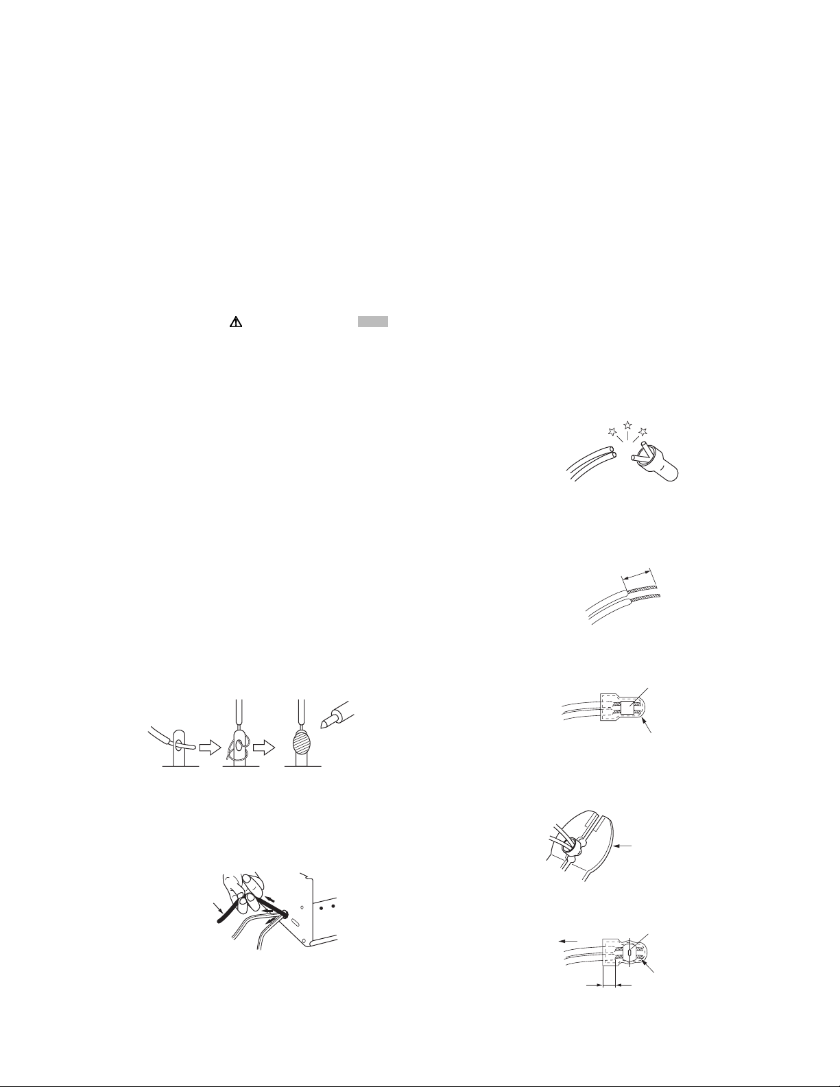
(12) Crimp type wire connectorIn such cases as when replacing
the power transformer in sets where the connections
between the power cord and power trans former primary
lead wires are performed using crimp type connectors, if
replacing the connectors is unavoidable, in order to prevent
safety hazards, perform carefully and precisely according
to the following steps.
• Connector part number :E03830-001
• Required tool : Connector crimping tool of the proper
type which will not damage insulated parts.
• Replacement procedure
a) Remove the old connector by cutting the wires at a
point close to the connector.Important : Do not
reuse a connector (discard it).
cut close to connector
Fig.1-1-3
b) Strip about 15 mm of the insulation from the ends
of the wires. If the wires are stranded, twist the
strands to avoid frayed conductors.
15 mm
Fig.1-1-4
c) Align the lengths of the wires to be connected.
Insert the wires fully into the connector.
Metal sleeve
Fig.1-1-1
(7) Observe that wires do not contact heat producing parts
(heatsinks, oxide metal film resistors, fusible resistors, etc.)
(8) Check that replaced wires do not contact sharp edged or
pointed parts.
(9) When a power cord has been replaced, check that 10-15
kg of force in any direction will not loosen it.
Power cord
Fig.1-1-2
(10) Also check areas surrounding repaired locations.
(11) Products using cathode ray tubes (CRTs)In regard to such
products, the cathode ray tubes themselves, the high
voltage circuits, and related circuits are specified for
compliance with recognized codes pertaining to X-ray
Connector
Fig.1-1-5
d) As shown in Fig.1-1-6, use the crimping tool to crimp
the metal sleeve at the center position. Be sure to
crimp fully to the complete closure of the tool.
1.2
5
2.0
5.5
Crimping tool
Fig.1-1-6
e) Check the four points noted in Fig.1-1-7.
Not easily pulled free
Wire insulation recessed
more than 4 mm
Crimped at approx. cente
of metal sleeve
Conductors extended
Fig.1-1-7
(No.YF289<Rev.003>)1-3
Page 4
1.1.2 Safety Check after Servicing
Examine the area surrounding the repaired location for damage
or deterioration. Observe that screws, parts and wires have been
returned to original positions, Afterwards, perform the following
tests and confirm the specified values in order to verify
compliance with safety standards.
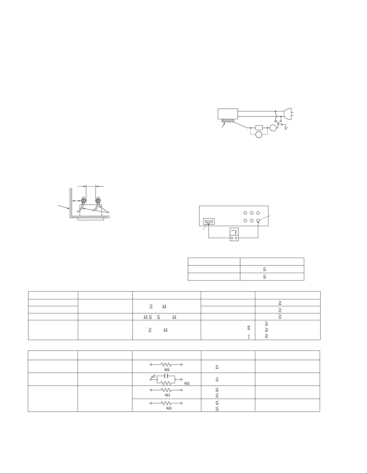
(1) Insulation resistance test
Confirm the specified insulation resistance or greater
between power cord plug prongs and externally exposed
parts of the set (RF terminals, antenna terminals, video and
audio input and output terminals, microphone jacks,
earphone jacks, etc.).See table 1 below.
(2) Dielectric strength test
Confirm specified dielectric strength or greater between
power cord plug prongs and exposed accessible parts of
the set (RF terminals, antenna terminals, video and audio
input and output terminals, microphone jacks, earphone
jacks, etc.). See Fig.1-1-11 below.
(3) Clearance distance
When replacing primary circuit components, confirm
specified clearance distance (d), (d') between soldered
terminals, and between terminals and surrounding metallic
parts. See Fig.1-1-11 below.
d
Chassis
d'
Power cord
primary wire
Fig.1-1-8
(4) Leakage current test
Confirm specified or lower leakage current between earth
ground/power cord plug prongs and externally exposed
accessible parts (RF terminals, antenna terminals, video
and audio input and output terminals, microphone jacks,
earphone jacks, etc.).
Measuring Method : (Power ON)Insert load Z between
earth ground/power cord plug prongs and externally
exposed accessible parts. Use an AC voltmeter to
measure across both terminals of load Z. See Fig.1-1-9
and following Fig.1-1-12.
ab
Externally
exposed
accessible part
Z
V
c
A
Fig.1-1-9
(5) Grounding (Class 1 model only)
Confirm specified or lower grounding impedance between
earth pin in AC inlet and externally exposed accessible
parts (Video in, Video out, Audio in, Audio out or Fixing
screw etc.).Measuring Method:
Connect milli ohm meter between earth pin in AC inlet and
exposed accessible parts. See Fig.1-1-10 and grounding
specifications.
AC inlet
Earth pin
Exposed accessible part
MIlli ohm meter
Grounding Specifications
Region
USA & Canada
Europe & Australia
Grounding Impedance (Z
Z 0.1 ohm
Z 0.5 ohm
)
Fig.1-1-10
AC Line Voltage
100 V
100 to 240 V
110 to 130 V
110 to 130 V
200 to 240 V
Region
Japan
USA & Canada
Europe & Australia
Insulation Resistance (R
R 1 M /500 V DC
1 M R 12 M /500 V DC
R 10 M /500 V DC
)
Dielectric Strength
AC 1 kV 1 minute
AC 1.5 kV 1 minute
AC 1 kV 1 minute
AC 3 kV 1 minute
AC 1.5 kV 1 minute
(
Class
(
Class
Clearance Distance (d), (d'
d, d' 3 mm
d, d' 4 mm
d, d' 3.2 mm
d 4 m m
)
d' 8 m m (Power cord
d' 6 m m (Primary wire
)
Fig.1-1-11
AC Line Voltage
100 V
110 to 130 V
110 to 130 V
220 to 240 V
Region
Japan
USA & Canada
Europe & Australia
Load Z
1
0.15
1.5
2
50
Leakage Current (i)
i 1 mA rms
i 0.5 mA rms
i 0.7 mA peak
i 2 mA dc
i 0.7 mA peak
i 2 mA dc
a, b, c
Exposed accessible parts
Exposed accessible parts
Antenna earth terminals
Other terminals
Fig.1-1-12
NOTE :
These tables are unofficial and for reference only. Be sure to confirm the precise values for your particular country and locality.
)
)
)
1-4 (No.YF289<Rev.003>)
Page 5
SECTION 2
SPECIFIC SERVICE INSTRUCTIONS
2.1 DIFFERENCE LIST The following table indicate main different points between models GZ-HD300AUS, GZ-HD300BUS, GZ-HD300RUS, GZ-HD310BUC and GZ-HD320BUS.
MODEL GZ-
HD300AUS
GZ-
HD300BUS
GZ-
HD300RUS
GZ-
HD310BUC
GZ-
HD320BUS
BODY COLOR BLUE BLACK RED BLACK BLACK
HDD 60GB 60GB 60GB 80GB 120GB
2.2 REPLACING HDD NOTE1) After HDD replacement, format the HDD first.
When the power is turned on after the HDD replacement, the
below "Warning screen" is displayed.
Be sure to format the HDD following the messages.
Be sure to turn off the power once after the formatting.
If the HDD recording is started without being turned off the power, normal recording cannot be performed although the recording will start.
NOTE2)
The picture title data needs to be written in the HDD.
Download the data and writing procedure from JS-NET.
Note that the picture title is a thumbnail image used in Creating Playlist including Titles and saved in the space where users cannot see.
< "Warning screen">
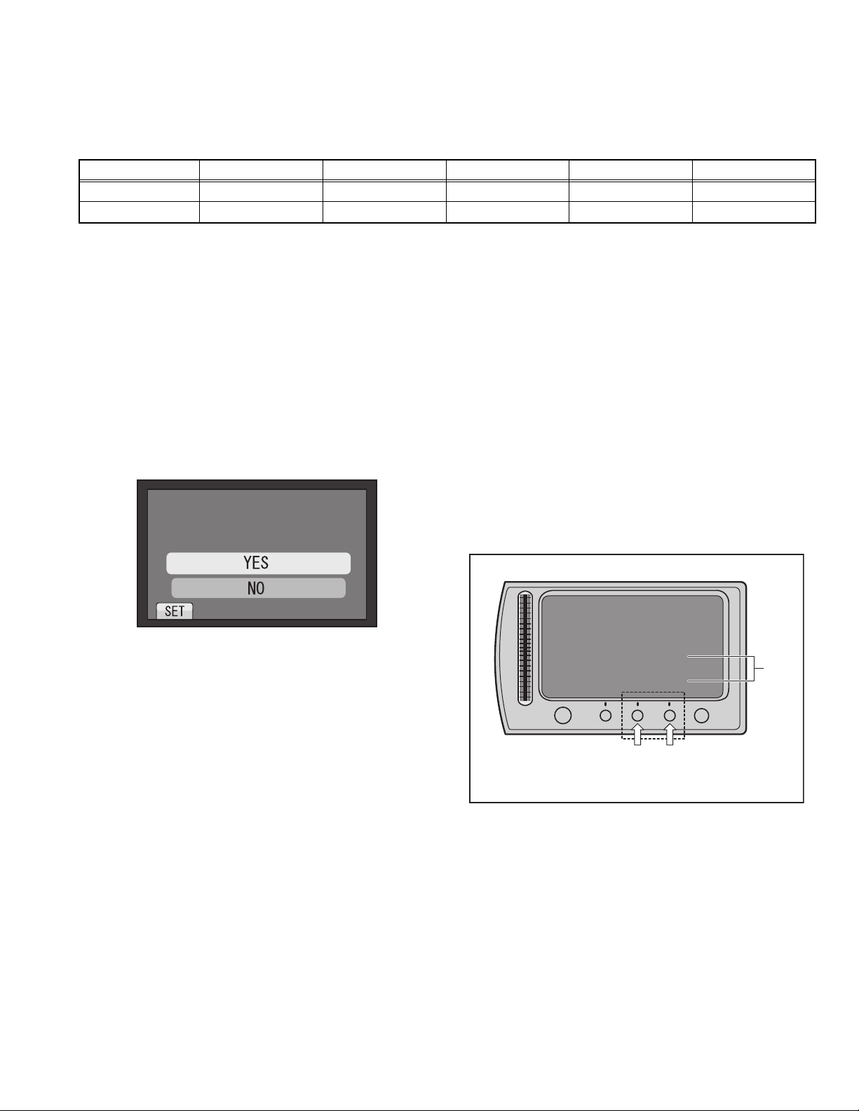
2.3 CHECKING THE CPU VERSIONS Procedure
(1) Open the MONITOR ASSY to turn the power ON.
(2) While halfway pressing and holding the [SNAPSHOT] but-
ton, repeat touching the buttons [A] and [B] 3 times in order:
[A]→[B]→[A]→[B]→[A]→[B].
(3) Release the halfway pressed [SNAPSHOT] button.
NOTE)
[VERSION INFO] is displayed on the monitor for about 5
seconds.
(4) Release the pressed [MENU] button, and the mode is
made clear.
NOTE)
When the mode is not canceled and the button is not operable, disconnect the battery or the DC cable to reset
the power.
0''&61(14/#6*#4&&+5-
&4+8'
#..#9+..$''4#5'&
&1;179#0661(14/#6!
Example:For GZ-HD320
Even when the mode is canceled, resetting the power is
recommended.
LCD MONITOR
Fig.2-2-1
VERSION INFO.
Model
Current Ver
EEPROM Ver
CAMCPU Ver 0.16
OK
Button[B]
NOTECurrent
CAMCPU Ver : CAMERA CPU VERSION
Ver : ELISE CPU VERSION
Name
GZ-HD320
1.05
12
Button[A]
NOTE
MENU
Fig.2-3-1
NOTE) Display of CAMCPU Ver: Camera CPU Version
As the Camera CPU Version cannot be displayed correctly,
check the version using Service Support System.
(No.YF289<Rev.003>)1-5
Page 6
2.4 FIRMWARE UPDATE
Connecting Everio to a PC via USB cable enables firmware update.
Connect a battery, capable of operating for 10 minutes or longer, and an AC adapter to Everio for update.
* The following procedure shows the monitor displays of the firmware update from ver. 0.82 to ver. 1.55.
* Use Windows XP or Windows Vista.
1.Preparation
(1)Preparation
Download the firmware update application software from JS-NET.
(2)Connection
Connect a battery that is capable of operating for 10 minutes or longer and an AC adapter to Everio.
* To ensure secure power supply during the update, update is disabled if either of them is not available.
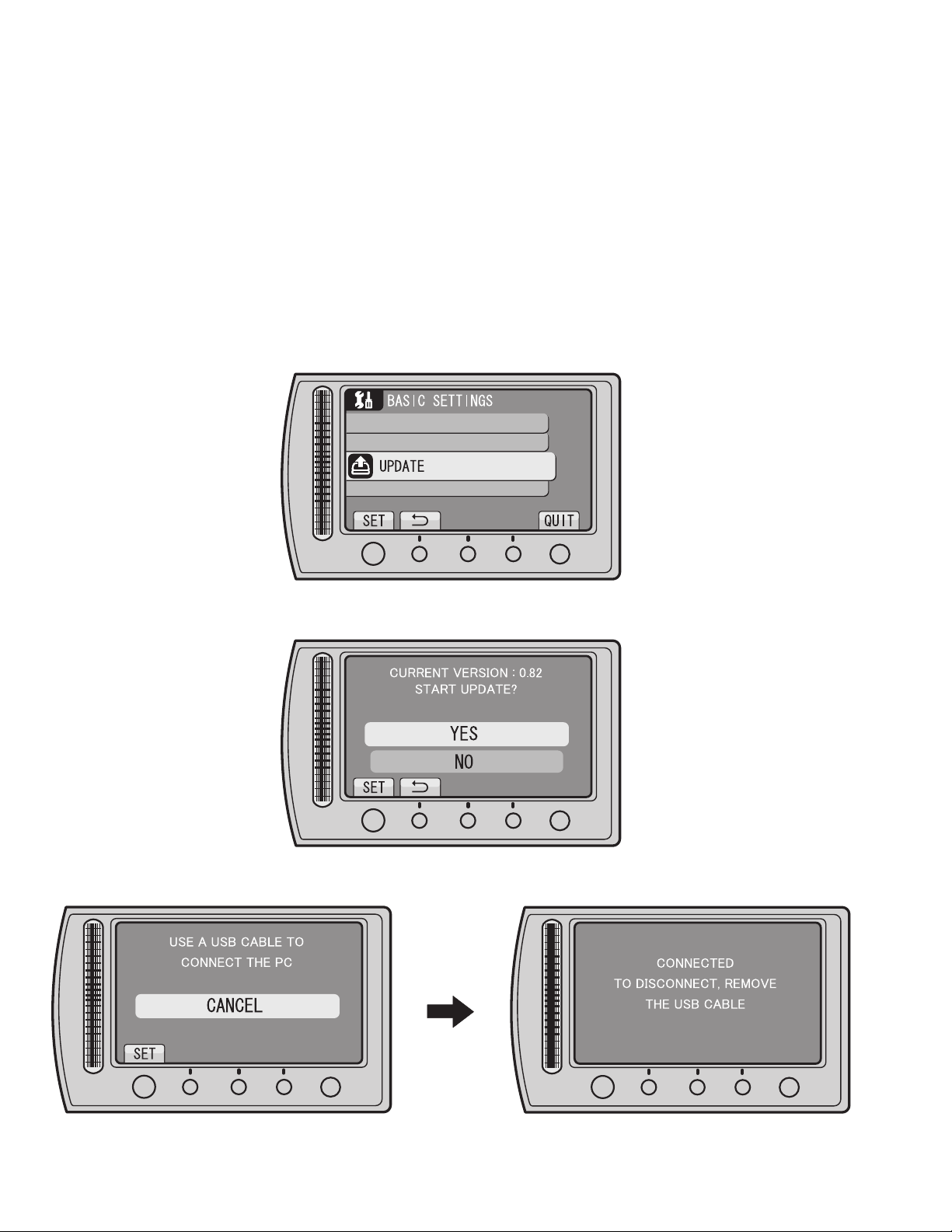
2.Firmware transfer
(1) Select "UPDATE" in the main menu of Everio.
MENU > BASIC SETTINGS > UPDATE
OK
Fig.2-4-1
(2)When the displayed current version is an old one, select "YES".
OK
Fig.2-4-2
(3)Follow the directions on the monitor to connect Everio to the PC via USB cable.
MENU
MENU
OK
1-6 (No.YF289<Rev.003>)
MENU
Fig.2-4-3
OK
MENU
Page 7
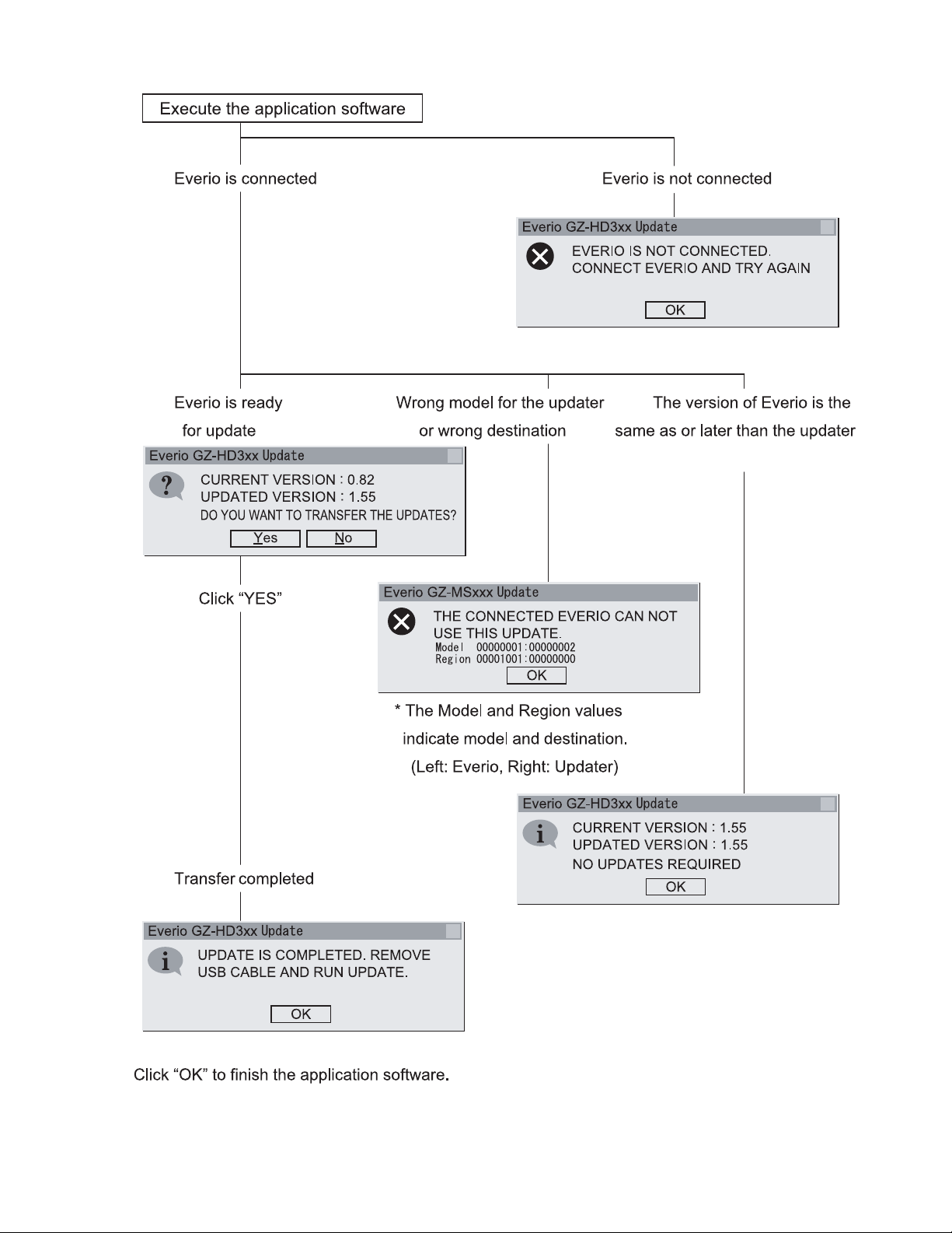
(4)Execute the downloaded application software.
×
×
×
×
×
Fig.2-4-4
(No.YF289<Rev.003>)1-7
Page 8
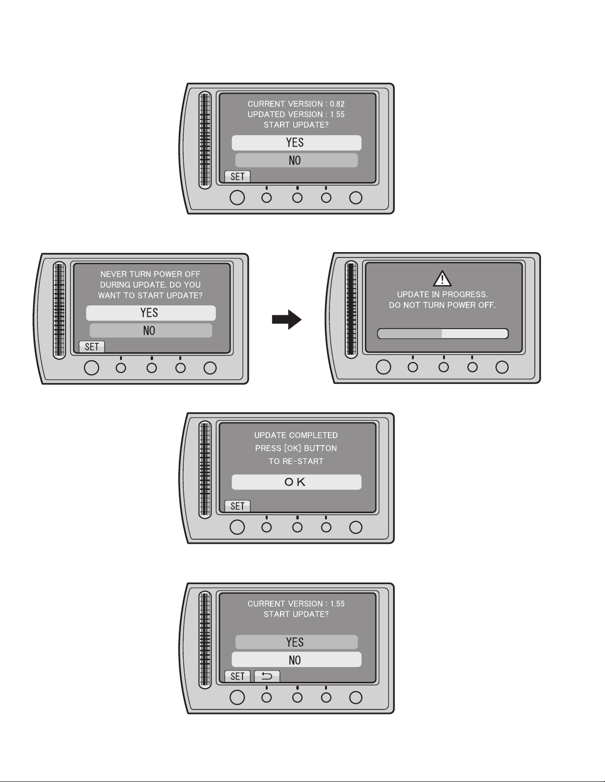
3.Execute update
(1)Disconnect the USB cable, and remove Everio from the PC.
(2)Check the current and updated versions, and then select "YES".
OK
Fig.2-4-5
(3)Carefully read and understand the warning, and then select "YES".
* It takes about 1 minutes and 30 seconds to complete the update.
OK
MENU
Fig.2-4-6
(4)Select "OK", and then re-start Everio.
MENU
OK
MENU
OK
Fig.2-4-7
(5)After the re-start, check that the current firmware is updated in UPDATE.
MENU > BASIC SETTINGS > UPDATE
OK
Fig.2-4-8
When the updated firmware version is confirmed, select "NO".
1-8 (No.YF289<Rev.003>)
MENU
MENU
Page 9
SECTION 3
DISASSEMBLY
3.1 BEFORE ASSEMBLY AND DISASSEMBLY
3.1.1 Precautions
• Be sure to disconnect the power supply unit prior to mounting
and soldering of parts.
• Prior to removing a component part that needs to disconnect
its connector(s) and its screw(s), first disconnect the wire(s)
from the connector(s), and then remove the screw(s).
• When connecting/disconnecting wires, pay enough attention
not to damage the connectors.
• When inserting the flat wire to the connector, pay attention to
the direction of the flat wire.
• Be careful in removing the parts to which some spacer or
shield is attached for reinforcement or insulation.
• When replacing chip parts (especially IC parts), first remove
the solder completely to prevent peeling of the pattern.
• Tighten screws properly during the procedures. Unless
otherwise specified, tighten screws at a torque of 0.088N
·cm). However, as this is a required value at the time of
(0.9kgf
production, use the value as a measuring stick when
proceeding repair services. (See "SERVICE NOTE" as for
tightening torque.)
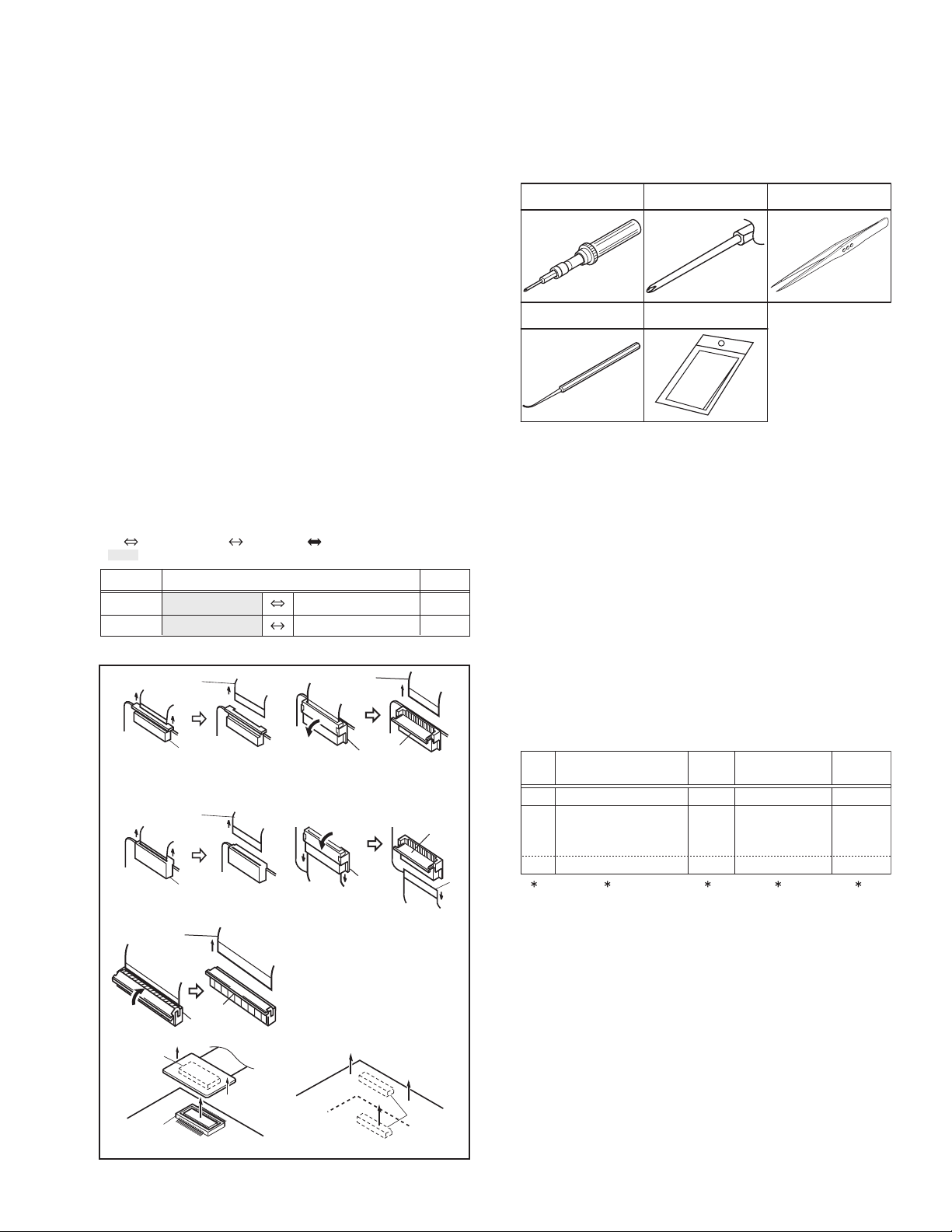
3.1.2 Destination of connectors
Two kinds of double-arrows in connection tables respectively
show kinds of connector/wires.
: Wire: Flat wire : Board to board (B-B)
: The connector of the side to remove
CONN. No. PIN No.CONNECTOR
CN2a
CN2b
MAIN CN101
MAIN CN103
MONI BW CN761
MINI BW CN762
3.1.3 Disconnection of connectors (Wires)
Wire
FPC Connector
· Pull both ends of the connector in the arrow
direction, remove the lock and disconnect the flat
wire.
Wire
FPC Connector
· Pull the both ends of the board in the direction of the
arrow, and remove the Connector.
Wire
Lock
FPC Connector
B-B Connector
B-B Connector
· Pull the both ends of the board in the direction of the arrow, and remove the B-B Connector.
· Extend the locks in the direction of the arrow for
unlocking and then pull out the wire. After
removing the wire, immediately restore the locks
to their original positions because the locks are
apt to come off the connector.
· Extend the locks in the direction of the arrow for
unlocking and then pull out the wire. After
removing the wire, immediately restore the locks
to their original positions because the locks are
apt to come off the connector.
· Extend the locks in the direction of the arrow for
unlocking and then pull out the wire. After
removing the wire, immediately restore the locks
to their original positions because the locks are
apt to come off the connector.
Wire
FPC Connector
FPC
Connector
Lock
B-B Connector
Fig.3-1-1
·m
40
10
Lock
Wire
3.1.4 Tools required for disassembly and assembly
Torque driver
YTU94088
Chip IC replacement jig
PTS40844-2
Bit
YTU94088-003
Cleaning cloth
KSMM-01
Tweezers
P-895
Fig.3-1-2
• Torque driver
Be sure to use to fastening the mechanism and exterior parts
because those parts must strictly be controlled for tightening
torque.
• Bit
This bit is slightly longer than those set in conventional torque
drivers.
• Tweezers
To be used for removing and installing parts and wires.
• Chip IC replacement jig
To be used for replacement of IC.
• Cleaning cloth
Recommended cleaning cloth to wipe down the video heads,
mechanism (tape transport system), optical lens surface.
3.2 ASSEMBLY AND DISASSEMBLY OF MAIN PARTS
3.2.1 Assembly and disassembly
When reassembling, perform the step(s) in reverse order.
STEP
No.
[1]
[2]
PART
TOP COVER ASSY
UPPER ASSY
(Inc. VF ASSY,
SPEAKER/MONITOR)
[8]
E.VF UNIT(B/W)
(∗1) Order of steps in Procedure
When reassembling, preform the step(s) in the reverseorder.
These numbers are also used as the identification (location)
No. of parts Figures.
(∗2) Part to be removed or installed.
(∗3) Fig. No. showing Procedure or Part Location.
(∗4) Identification of part to be removed, unhooked, unlocked,
released, unplugged, unclamped or unsoldered.
S = Screw L = Lock, Release, Hook
SD = Solder CN = Connector
[Example]
• 4 (S1a) = Remove 4 S1a screws.
• 3 (L1a) = Disengage 3 L1a hooks.
• 2 (SD1a) = Unsolder 2 SD1a points.
• CN1a = Remove a CN1a connector.
(∗5) Adjustment information for installation.
Fig.
No.
4(S1a), 3(L1a),CN1a
C1
(S2a),2(S2b),3(S2c)
C2-1
2(SD1a),
L2,CN2a,b
2(S8),L8,CN8a
C2-2
POINT
( 4) ( 5)( 2) ( 3)( 1)
NOTE
-
-
NOTE 8
(No.YF289<Rev.003>)1-9
Page 10

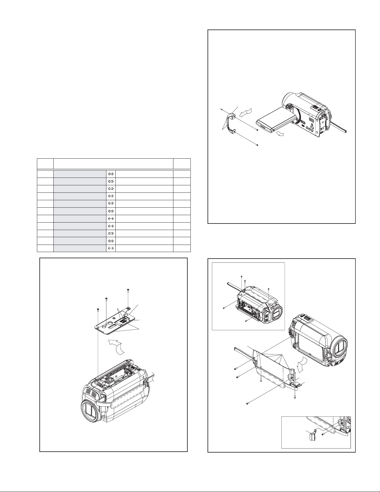
3.2.2 Assembly/Dissambly of cabinet parts and electrical parts
z Disassembly procedure
STEP
PART NAME
No.
[1]
B.COVER(N)ASSY
[2]
COVER (HINGE) ASSY
[3]
HDD COVER ASSY
[4]
TOP COVER
[5]
HDD
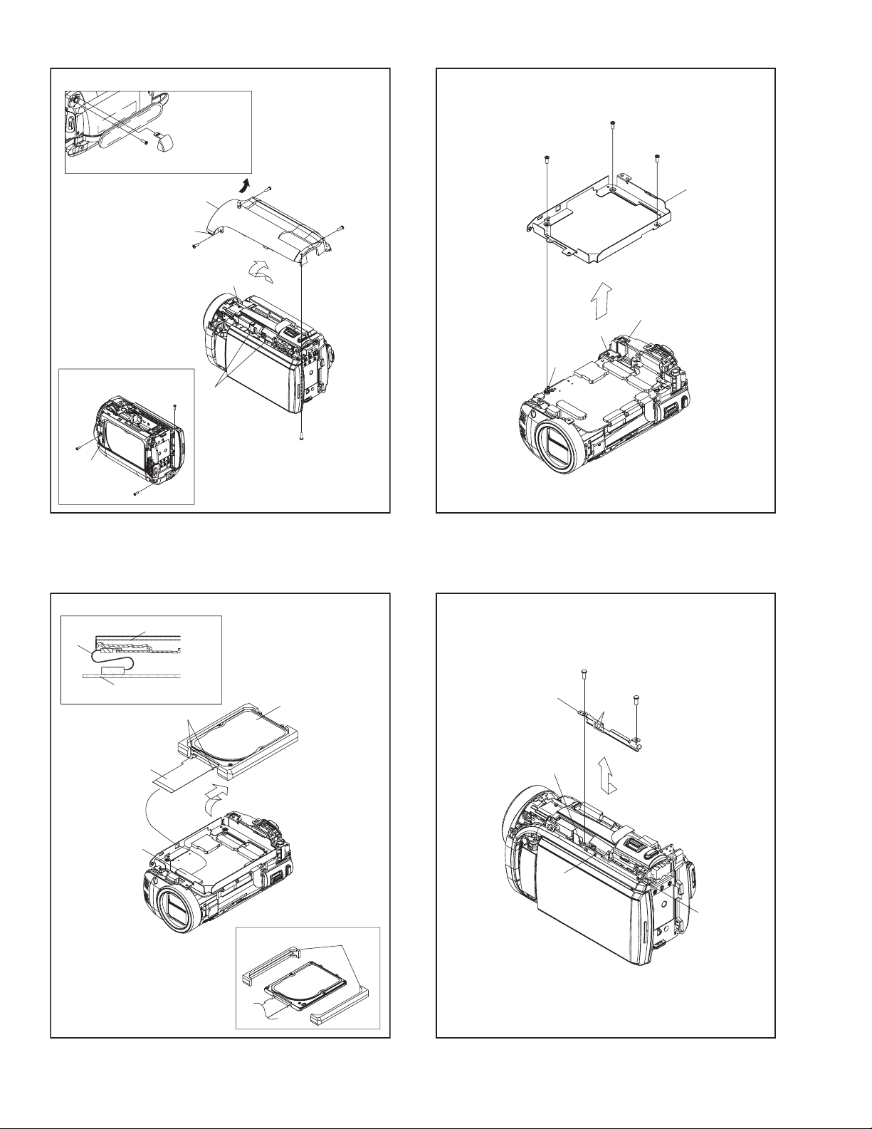
[6]
HDD CASE ASSY
[7]
BKT(O.TOP)
[8]
ORNAMENT(TOP)
[9]
UPPER ASSY
REAR COVER ASSY
[10]
(Inc.REAR BOARD ASSY,ZOOM UNIT)
[11]
ZOOM UNIT
[12]
REAR BOARD ASSY
[13]
JACK BOARD ASSY
[14]
FRONT ASSY
[15]
MAIN BOARD ASSY
[16]
FRAME (PLATE) ASSY
[17]
OP BLOCK ASSY
[18]
BARRIER UNIT
[19]
HOOD(SCERW)
[20]
MIC
[21]
OPE BOARD ASSY
[22]
SPEAKER
[23]
MONITOR ASSY
Fig.
No.
3-2-1
3-2-2
3-2-3
3-2-4
3-2-5
3-2-6
3-2-7
3-2-8
3-2-9
3-2-10
3-2-11
3-2-12
3-2-13
3-2-14
3-2-15
3-2-16
3-2-17
3-2-18
3-2-19
3-2-20
3-2-21
3-2-22
POINT NOTE
3(S1),2(L1a), 2(L1b)
2(S2),2(L2)
4(S3a),S3b,L3a,b,4(L3c)
2(S4a),2(S4b),L14a,2(L4b),L4c
CN5
3(S6),L6a,b,c
2(S7),L7a,b,2(L7c),L7d
L8a,b,c,d,e
CN9,S9a,b,L9
CN10a,b,2(S10),L10a,b
S11,L11a,b
S12,L12a,b
CN13,2(S13),2(L13a)
S13,L13b,BKT(HDMI),PLATE(HDMI)
CN14a,b.L14a,b,c
2(S15),L15,CN15a,b
2(S16),L16a,b,c
3(S17),FRAME ASSY
S18a,2(S18b)
L19a,b
S20,L20a,b,PLATE(MIC)
S21a,CN21a,2(L21a),L21b,
CN21b,2(S21b),L21c,d
S22,BKT(SPEAKER),SPACER(SPK)
2(S23),L23
NOTE1
NOTE2
NOTE3
NOTE4
NOTE5a,b,c,d,e,f
-
-
NOTE8
NOTE9
-
-
-
NOTE13
-
NOTE14a,b
NOTE15
-
NOTE17a,b
NOTE18
-
NOTE20
NOTE21a,b,c,d,e
NOTE22a,b
NOTE23
NOTE1:
When removing the BOTTOM COVER ASSY, open and pull
up the COVER (SD).
NOTE2:
When removing the COVER (HINGE) ASSY, open the
MONITOR ASSY, remove the 2 screws, rotate the MONI-
TOR ASSY 90°, tilt it to the rear side, and then pull out the
COVER (HINGE) ASSY.
NOTE3:
Screw No.8 is located under the JACK COVER (USB). Remove or slide the JACK COVER (USB) to remove the screw.
NOTE4:
Screw No.11 is located under the JACK COVER (AV). Remove or slide the JACK COVER (AV) to remove the screw.
NOTE5a:
During the procedure, be careful in handling the parts. Pay
special attention not to give any external shock to the HDD.
NOTE5b:
When the HDD is replaced, be sure to refer to Replacing
HDD in "SECTION2 SPECIFIC SERVICE INSTRUCTIONS"
for the procedure after HDD replacement.
NOTE5c:
Be careful as the RUBBER SPACERS on both sides are
easily come off when the HDD is removed from the main
unit.
If the RUBBER SPACERS come off, be sure to attach them
in the correct direction shown in the figure.
NOTE5d:
When connecting the FPC to the connector, insert the FPC
straight into the connector. When locking the connector, be
careful not to give so much load that it bends the board.
NOTE5e:
In this procedure, the FPC connected to the HDD connector
is not removed. If the FPC is removed due to broken wire,
be careful in attachment direction.
Be sure to connect the STOPPER side to the HDD.
Pay attention as wrong attachment could damage the HDD.
NOTE5f:
Be careful with the wiring.
NOTE8:
During the procedure, be careful not to break the parts.
NOTE9:
Please refer to Fig.3-2-20 and the following procedure for removing the UPPER ASSY.
NOTE13:
The JACK BOARD ASSY is attached between the PLATE
(HDMI) and the BRACKET (HDMI). For replacement, remove the screw (No.28) and disassemble them if necessary.
NOTE14a:
When attaching the FRONT ASSY, be careful in handling
the wire and the FPC.
NOTE14b:
Please refer to Fig.3-2-18 and the following procedure for removing the FRONT ASSY.
NOTE15:
When attaching the MAIN BOARD ASSY, be careful in handling
the WIRE (CMOS).
NOTE17a:
Refer to 3.2.3 Assembly/Disambly of [17] OP BLOCK ASSY/
CMOS BOARD ASSY of OP BLOCK ASSY.
NOTE17b:
When attaching the OP BLOCK ASSY, be careful in handling the WIRE (CMOS).
NOTE18:
When attaching the BARRIER UNIT, be careful in handling
the WIRE (MIC).
NOTE20:
When attaching the MIC, attach the BARRIER UNIT before
handling the WIRE (MIC). (Refer to NOTE 18.)
NOTE21a:
When removing, remove the screw No.40 first to release the
FPC, and then pull out the FPC from the connector.
NOTE21b:
When removing the OPE BOARD ASSY, release the WIRE
(SPK) from the HOOK (L21b) first, and then pull out the
WIRE (SPK) from the connector.
NOTE21c:
When attaching, make sure that the LEVER of the
SW(S408) interlocks with the KNOB (SLIDE).
1-10 (No.YF289<Rev.003>)
Page 11
NOTE21d:
When attaching, be careful with the wiring.
NOTE21e:
During the procedure, be careful not to damage the parts.
When attaching the OPE BOARD ASSY with the MONITOR
ASSY closed, be especially careful not to break the
SWITCH (S401).
NOTE22a:
When removing the SPEAKER, be careful in handling as the
SPACER (SPK) may come off with the SPEAKER.
NOTE22b:
When attaching, be careful with the wiring.
As the final wiring is performed when attaching the OPE
BOARD ASSY, leave the wire as shown in the drawing.
NOTE23:
Refer to 3.2.4 Disassembly of [23] MONITOR ASSY.
z Destination of connectors
CN.
No.
CN5 MAIN CN102 HDD - 40
CN9 MAIN CN101 OPE CN401 36/40
CN10a MAIN CN104 OPE UNIT
CN10b MAIN CN103 REAR CN602 32/36
CN13 MAIN CN114 JACK - 40
CN14a MAIN CN111 LENS BARRIER - 6
CN14b MAIN CN107 MIC - 4
CN15a MAIN CN105 CMOS CN4001 22
CN15b MAIN CN106 OP BLOCK - 25
CN21a OPE CN402 MONITOR CN703 28/29
CN21b OPE CN401 SPEAKER - 2
CONNECTOR
PIN
No.
- 12
L2
[2]
a
b
4
(S2)
5
(S2)
Fig.3-2-2
a
b
NOTE2
1
(S1)
2
(S1)
L1a
3
(S1)
[1]
NOTE1
COVER(SD)
L1b
6
(S3a)
10
(S3b)
9
(S3a)
(S3a)
[3]
9
(S3a)
NOTE3
(S3a)
(S3b)
7
8
10
(S3a)
6
8
(S3a)
L3c
(S3a)
NOTE3
JACK
COVER
(USB)
L3b
L3a
7
8
(S3a)
Fig.3-2-1
Fig.3-2-3
(No.YF289<Rev.003>)1-11
Page 12
NOTE4
14
(S4b)
L4a
11
(S4a)
11
(S4a)
JACK
COVER
(AV)
L4c
13
(S4b)
12
(S4a)
[4]
L4b
L4a
14
(S4b)
12
(S4a)
NOTE4
11
(S4a)
15
(S6)
16
(S6)
17
(S6)
[6]
L6a
L6b
L6c
NOTE5f
FPC
MAIN BOARD ASSY
NOTE5e
FPC
NOTE5d
CN5
HDD
STOPPER
Fig.3-2-4
NOTE5a,b
NOTE5c
RUBBER SPACER
[5]
[7]
L7d
L7b
Fig.3-2-6
18
(S7)
19
(S7)
L7c
L7a
1-12 (No.YF289<Rev.003>)
Fig.3-2-5
Fig.3-2-7
Page 13

NOTE8
L8c
L8b
[10]
CN10a
L10b
L8d
L8e
[8]
Fig.3-2-8
CN9
L8a
CN10b
L10a
22
(S10)
23
(S10)
Fig.3-2-10
24
(S11)
[11]
20
(S9a)
[9]
NOTE9
L9
Fig.3-2-9
L11b
21
(S9b)
CN9
L11a
Fig.3-2-11
(No.YF289<Rev.003>)1-13
Page 14

[10]
NOTE14b
[14]
L14c
L14b
L14a
L12b
L12a
NOTE13
GASKET
28
(S13)
[12]
Fig.3-2-12
25
(S12)
FPC(LENS BARR.)
NOTE14a
WIRE(MIC)
30
(S15)
29
(S15)
CN14a(FPC)
WIRE(MIC)
FPC(LENS BARR.)
Fig.3-2-14
[15]
CN14b(WIRE)
L13b
GASKET
[13]
26
(S13a)
27
(S13a)
1-14 (No.YF289<Rev.003>)
Fig.3-2-13
CN13
L13a
GASKET
L15
CN15b
CMOS WIRE
Fig.3-2-15
NOTE15
CN15a
NOTE15
MAIN PWB
Page 15

L16b
32
(S16)
L16c
31
(S16)
[16]
L16a
[18]
(S18b)
37
(S18b)
38
NOTE18
WIRE(MIC)
NOTE18
WIRE(MIC)
36
(S18a)
NOTE17b
Fig.3-2-16
(S17)
34
(S17)
35
33
(S17)
[19]
L19a
L19b
Fig.3-2-18
39
(S20)
PLATE(MIC)
[20]
NOTE20
WIRE(MIC)
FRME ASSY
0.118Nm (1.2kgfcm)
Fig.3-2-17
NOTE17a
[17]
FRONT COVER ASSY
L20b
L20a
Fig.3-2-19
(No.YF289<Rev.003>)1-15
Page 16

[21]
41
(S21b)
42
(S21b)
CN21b
CN21a
NOTE21e
SW(S401)
WIRE(SPK)
a
L21b
L21a
NOTE21a
40
(S21a)
FPC
NOTE21c
[21]
CN21b
WIRE(SPK)
L21b
NOTE21eNOTE21b,d
SW(S401)
L21d
L21c
NOTE22b
WIRE(SPK)
NOTE22b
WIRE(SPK)
40
(S21a)
NOTE21a
BKT(SPACER)
[22]
a
FPC
43
(S22)
Fig.3-2-20
SW(S408)
KNOB(SLIDE)
SW(S408)
LEVER
[21]
44
(S23)
45
(S23)
[23]
NOTE23
NOTE22a
SPACER(SPK)
1-16 (No.YF289<Rev.003>)
L23
Fig.3-2-21 Fig.3-2-22
Page 17

3.2.3 Assembly/Disambly of [17] OP BLOCK ASSY/CMOS BOARD ASSY
zPrecautions
(1) Be careful in handling the LENS components.
Pay special attention to the surfaces to protect them from
stains, dust, or scratches.
If the surfaces are soiled with finger prints or other stains,
wipe them off with silicon paper, clean chamois leather,
or recommended cleaning cloth.
zDisassembly of OP BLOCK ASSY / CMOS BOARD ASSY
(1) Remove the screw (1), and then remove the
SHIELD(CMOS).
NOTE17a:
When reMmoving the SHIELD(CMOS), be careful in
handling as the SHIELD(CMOS) or CMOS BOARD
ASSY may be removed together with the HEAT
SHEET attached.
(2) Remove the 2 screws (2,3), and then remove the CMOS
FRAME ASSY.
NOTE17b:
When removing the CMOS FRAME ASSY, be careful
in handling as the CMOS FRAME ASSY may be removed together with the SHEET attached.
zAssembly of OP BLOCK ASSY / CMOS BOARD ASSY
zReplacement of service repair parts
NOTE17c:
(1) The SHEET is set in the OP BLOCK ASSY.
(2) Attach the CMOS FRAME ASSY first,so that the SHEET
stays in place, and tighten with the 2 screws (2,3).
(3) Attach the SHIELD(CMOS) first, and tighten with the
screw (1).
The service repair parts for the OP BLOCK ASSY are as listed below.
When replacing parts, be careful not to cut the FPCs or damage any parts by soldering (excessive heat).
(1) FOCUS MOTOR UNIT
(2) ZOOM MOTOR UNIT
(3) AUTO IRIS UNIT
NOTE 17d:
When replacing the FOCUS MOTOR UNIT or the ZOOM
MOTOR UNIT, solder the FPC at a space of about 0.1
mm above the terminal pin.
NOTE 17e:
The AUTO IRIS UNIT includes the FPC ASSY and two sensors.
The CMOS BOARD ASSY is included in CMOS
FRAME ASSY.
Replace the CMOS BOARD ASSY as a CMOS
FRAME ASSY, not as a single part replacement.
SD17b
6
(S17b)
ZOOM MOTOR
UNIT
7
(S17b)
10
(S17b)
8
(S17b)
9
(S17b)
NOTE17d
AUTO IRIS UNIT
4
(S17b)
FOCUS MOTOR
UNIT
5
(S17b)
SHIELD(CMOS)
NOTE17a
HEAT SHEET
NOTE17c
CMOS FRAME ASSY
CMOS BOARD ASSY
is contained.
NOTE17b
SHEET
2
(S17b)
1
(S17a)
3
(S17b)
OP BLOCK ASSY
OP BLOCK ASSY
0.078Nm (0.8kgfcm)
0.147 Nm (1.5kgfcm)
Fig.3-2-23
(No.YF289<Rev.003>)1-17
Page 18

3.2.4 Disassembly of [23] MONITOR ASSY
zCAUTIONS
(1) During the procedure, be careful in handling the LCD
MODULE and other parts. Pay special attention not to
damage or stain the monitor screen.
If fingerprints are left on the screen, wipe them with clean
chamois leather or a cleaning cloth.
z Removing MONITOR ASSY
(1) Remove the 2 screws (1,2).
(2)
Turn the HINGE UNIT ASSY 90°, and remove the 2 screws
(3,4).
(3) Remove the MONI.COVER ASSY by removing the 8
hooks (L23a-h).
(4) Release the lock of the connector (CN23a), and remove
ASSY
the HINGE UNIT
NOTE23a:
During the procedure, be careful in handling the FPC.
(5) Release the lock of the connectors (CN23b,c), and pull
out the FPC.
Remove the screw (5), and remove the MONITOR BOARD
(6)
ASSY .
NOTE23b:
During the procedure, be careful in handling the FPC.
(7) Remove the SHEET (M.REF), LIGHT GUIDE, SHEET(M/
DIFF), and the SHEET(BEF).
NOTE23c:
When attaching, insert one side of the SHEET (M/
DIFF) under the LCD CASE RIB.
NOTE23d:
When attaching, insert each tab on both sides of the
SHEET (M.REF) into the LCD CASE notch.
(8) Remove the LCD CASE, SHEET(COVER), LCD MOD-
ULE, SPACER(LCD) and the LCD BKT.
NOTE23e:
During the procedure, handle the five parts (LCD
CASE, SHEET(COVER), LCD MODULE, SPACER(LCD) and the LCD BKT) together.
NOTE23f:
The SENSOR BOARD ASSY is originally affixed to the
MONI.CASE ASSY using jigs and they have structures difficult to replace.
If replacement is required, please refer to the NOTE
and follow the operation procedure.
Assembly/Disambly of MONITOR CASE ASSY/SENSOR BOARD ASSY
z
Operation procedure
• Removing the part which is to be reused
Remove the SENSOR BOARD ASSY from the MONI.CASE
(1)
ASSY by gradually peeling off from the HINGE UNIT ASSY side.
NOTE23g:
During the procedure, be careful not to break.
Prepare the new SENSOR BOARD ASSY and D.FACE
TAPE and use them in place of the removed parts.
•
Completely peel off the remaining tape pieces of the D. FACE
TAPE left on the part to be reused (MONI.CASE ASSY).
NOTE23h:
Make sure that there are no D. FACE TAPE pieces or
foreign substances left on the surfaces. If necessary,
clean the surfaces using alcohol etc.
• Affixing the D. FACE TAPE to the SENSOR BOARD
(1) Affix the D. FACE TAPE to the SENSOR BOARD ASSY.
NOTE23j:
Securely fix the D. FACE TAPE, and then affix the SENSOR BOARD ASSY to the D. FACE TAPE by adjusting
the four frames of the SENSOR BOARD ASSY to the
1-18 (No.YF289<Rev.003>)
by lifting it up.
frame of the D. FACE TAPE. Evenly press over the paper backing of each long / short side of the L shape.
(2) Peel off the paper backing.
NOTE23k:
When removing the paper backing, check that there
are no foreign substances or air bubbles on the tape.
If there are foreign substances etc., completely remove them and continue the affixing procedure.
• Affixing the SENSOR BOARD ASSY to the MONI. CASE
(1) Affix the SENSOR BOARD ASSY to the MONI. CASE
NOTE23m:
When affixing, adjust the position of the long side of the
L shape to avoid misalignment, and then press evenly.
Be sure to press hard for 10 seconds or more on each
long/ short side of the L shape for even adhesion.
During the procedure, be careful to prevent foreign
substances or air bubbles from entering.
(2) After the replacement, make sure that there are no bro-
ken or deformed parts or any abnormalities.
Use the service software for the operation check of the
touch sensor sensitivity.
NOTE23g,j,k
SENSOR BOARD ASSY
NOTE23j,k
D.FACE TAPE
DETACHMENT PAPER
NOTE23j,k
SENSOR BOARD ASSY
D.FACE TAPE
Fig.3-2-24
zRemoving HINGE UNIT ASSY
(1) Remove the HINGE COVER(U).
(2) Remove the HINGE COVER(L).
(3) Remove the MAGNET.
NOTE23n:
During the procedure, be careful in handling the FPC.
During the procedure, be careful in handling the MAGNET.
When attaching, set the N pole outside as shown in the
figure. Be careful when removing as there is no marking.
NOTE23p:
During the procedure, be careful in handling the FPC.
NOTE23q:
The FPC, with its connection to the MONITOR BOARD
ASSY facing inward, is rolled around the axis (shaft) of
the HINGE UNIT ASSY rotation 2.5 rounds (2.5times).
Page 19

0.118 Nm (1.2kgfcm)
NOTE23p
FPC
<NOTE23p,q>
FPC
HINGE UNIT
HINGE COVER(U)
L23n
L23m
L23q
HINGE COVER(L)
HINGE UNIT
L23p
NOTE23n
MAGNET
3
(S23a)
NOTE23a
HINGE UNIT
ASSY
CN23a
L23a
4
(S23a)
L23k
L23e
CN23b
1
(S23a)
L23c
b
L23j
L23h
L23e
L23d
CN23c
MONI. COVER
ASSY
MONI. COVER
ASSY
L23g
L23f
2
(S23a)
<MONI. CASE SIDE>
NOTE23e
(REINFORCED SIDE)
LCD BKT
SPACER(LCD)
LCD MODULE
SHEET(COVER)
LCD CASE
CN20b
NOTE23d
NOTE23c
NOTE23c
LCD CASE
LIB
CN23c
g
b
f
c
j
h
f,h
c
FPC
NOTE23b
g,j
5
(S23b)
MONI. BOARD
ASSY
d
e
SHEET(M.REF)
m
k
LIGHT GUIDE
SHEET(M/DIFF)
SHEET(BEF)
e
m
k
d
NOTE23b
FPC
<MONI. COVER SIDE>
SENSOR BOARD
Fig.3-2-25
ASSY
NOTE23f,j
MONI. CASE ASSY
NOTE23f,g,h,m
(No.YF289<Rev.003>)1-19
Page 20

SECTION 4
ADJUSTMENT
4.1 PREPARATION
4.1.1 Precaution
Camera system and deck system of this model are specially
adjusted by using PC.
However, if parts such as the following are replaced, an
adjustment is required. The adjustment must be performed in a
Service Center equipped with the concerned facilities.
• EEP ROM (IC1005 of MAIN board)
• OP BLOCK ASSY
• MONITOR ASSY
In the event of malfunction with electrical circuits, first find a
defective portion with the aid of proper test instruments as shown
in the following electrical adjustment procedure, and then
commence necessary repair/ replacement/adjustment.
• In observing chip TP, use IC clips, etc. to avoid any stress.
Prior to replacement of chip parts (especially IC), remove the
solder completely to prevent peeling of the pattern.
• Use a patch cord if necessary. As for a patch cord, see the
BOARD INTERCONNECTIONS.
• Since connectors are fragile, carefully handle them in
disconnecting and connecting the FPC.
4.1.2 Required test equipment
• Personal computer (for Windows)
• Color TV monitor
• Oscilloscope (dual-trace type, observable 100MHz or higher
frequency). The one observable 300 MHz or higher frequency
is recommended.
• Digital voltmeter
• DC power supply or AC adapter
• Frequency counter (with threshold level adjuster)
4.1.3 Tools required for adjustment
Torque Driver
YTU94088
Chip IC Replacement Jig
PTS40844-2
INF Adjustment Lens Holder
YTU94087
Gray Scale Chart
YTU94133A
Service Support System
YTU94057-117
Bit
YTU94088-003
Cleaning Cloth
KSMM-01
Mini Stand
YTU93108
Color Bar Chart
YTU94133C
Communication Cable
YTU93111-1
Tweezers
P-895
INF Adjustment Lens
YTU92001D
Light Box Assembly
YTU93096B
Focus Chart
YTU92001-018
1-20 (No.YF289<Rev.003>)
PC Cable
QAM0099-002
IDE Adapter
YTU96041
Jig Connector Cable
YTU93106D
IDE Adapter
YTU96043
Charing Battery Adjuatment Jig
YTU93112A
FPC Wire
YTU94165-40
• Torque Driver
Be sure to use to fastening the mechanism and exterior parts
because those parts must strictly be controlled for tightening
torque.
• Bit
This bit is slightly longer than those set in conventional torque
drivers.
• Tweezers
To be used for removing and installing parts and wires.
Page 21

• Chip IC Replacement Jig
To be used for adjustment of the camera system.
• Cleaning Cloth
Recommended the Cleaning cloth to wipe down the video
heads, mechanism (tape transport system), optical lens surface.
• INF Adjustment Lens
To be used for adjustment of the camera system. For the
usage of the INF adjustment lens, refer to the Service Bulletin
No. YA-SB-10035.
• INF Adjustment Lens Holder
To be used together with the Camera stand for operating the
Videocamera in the stripped-down condition such as the status without the exterior parts or for using commodities that are
not yet conformable to the interchangeable ring. For the usage
of the INF lens holder, refer to the Service Bulletin No. YA-SB-
10035.
• Mini Stand
To be used together with the INF adjustment lens holder. For
the usage of the Mini stand, refer to the Service Bulletin No.
YA-SB-10035.
• Light Box Assembly
To be used for adjustment of the camera system. For the
usage of the Light box assembly, refer to the Service Bulletin
No. YA-SB-10035.
• Gray Scale Chart
To be used for adjustment of the camera system. For the
usage of the INF adjustment lens, refer to the Service Bulletin
No. YA-SB-10035.
• Color Bar Chart
To be used for adjustment of the camera system. For the
usage of the INF adjustment lens, refer to the Service Bulletin
No. YA-SB-10035.
• Focus Chart
To be used for adjustment of the camera system. For the
usage of the INF adjustment lens, refer to the Service Bulletin
No. YA-SB-10035.
• Service Support System
To be used for adjustment with a personal computer. Software
can be downloaded also from JS-net.
• Communication Cable
Connect the Communication cable between the PC cable and
Jig connector cable when performing a PC adjustment.
• PC Cable
To be used to connect the Videocamera and a personal computer
with each other when a personal computer issued for adjustment.
• Jig Connector Cable
Connected to JIG CONNECTOR of the main board and used
for electrical adjustment, etc.
• Charging Battery Adjustment Jig
This Jig is used for the adjustment of the camcorders that have
Main Body battery charging function.
• IDE Adapter(YTU96041)
To be used for HDD test.
• IDE Adapter(YTU96043)
To be used for HDD test.
• FPC Wire
To be used for connecting the HDD to the IDE adapter.
4.2 JIG CONNECTOR CABLE CONNECTION
Connection procedure
NOTE
• Be sure to turn the power “OFF”, when connecting the JIG
CONNECTOR CABLE.
If the JIG CONNECTOR CABLE is connected with the power “ON”, communication error may occur.
• Remove the 3 screws (1-3), and then remove the B.COV-
ER ASSY.
3
B.COVER ASSY
2
1
JIG
CONNECTOR
JIG CONNECTOR
CABLE
SERVICE
SUPPORT
SYSTEM
RS232C
COMMUNICATION
CABLE
JIG CONNECTOR
TO AL_2.8V
TO IF_RX
TO IF_TX
TO GND
BLUE
WHITE
BLACK
or
COMMUNICATION
CABLE
RED
COM PORT
PC CABLE
MENU
PERSONAL COMPUTER
Fig.4-2-1
JIG CONNECTOR CABLE [YTU93106D]
1630
115
Fig.4-2-2
(No.YF289<Rev.003>)1-21
Page 22

Jig connector diagrams
JIG CONNECTOR CABLE (YTU93106D)
MAIN CN110
DSP_TDO
DSP_TCK
DSP_TMS
DSP_TDI
XDSPTRST
XDSPSRST
REG_2.83V
UARXD0
UATXD0
AL_2.8V
IF_TX
IF_RX
NC
SYS_RSTL
OCD_SCL
CAPSENS_DT
NC
GND
OCD_SDA
GND
MVD
IRU
ISSP_DATA
NC
NC
EXTRG0
DSP_RTCK
KENTO
GND
KENTO2
JIG CONN. BOARD
(PIN NO.)
1
16
2
17
3
18
4
19
5
20
6
21
7
22
8
23
9
24
10
25
11
26
12
27
13
28
14
29
15
30
1
2
XDSPTRST
3
REG_2.83V
4
5
6
7
8
9
10
11
ISSP_DATA
12
13
DSP_RTCK
14
15
16
17
XDSPSRST
18
19
20
21
SYS_RSTL
22
CAPSENS_DT
23
24
25
26
27
28
29
30
DSP_TDO
DSP_TMS
UATXD0
IF_TX
NC
OCD_SCL
NC
OCD_SDA
MVD
NC
GND
DSP_TCK
DSP_TDI
UARXD0
AL_2.8V
IF_RX
GND
GND
IRU
NC
EXTRG0
KENTO
KENTO2
Fig.4-2-3
1-22 (No.YF289<Rev.003>)
Page 23

4.3 IDE ADAPTER AND FPC WIRE
• IDE ADAPTER and FPC WIRE are used for HDD test.
Check with the NOTE, and then refer to the below figure (Fig. 4-3-1, Fig.4-3-2) for the connection procedure.
<TYPE-T>
FPC WIRE(Parts No.:YTU94165-40)
<BACK SIDE><FRONT SIDE>
HDD HDD
IDE ADAPTER CONNECTOR
<TYPE-S>
LABEL
Fig.4-3-1
FPC WIRE(Parts No.:YTU94165-40)
<BACK SIDE><FRONT SIDE>
HDD HDD
CONNECTOR
Fig.4-3-2
<NOTE>
• During the procedure, be careful in handling the parts. Pay special attention not to give any external shock to the HDD.
• There are two types of IDE ADAPTER (Parts Number: YTU96041, YTU96043). Either type can be used.
• Using the FPC WIRE originally used with this unit will damage the HDD.
Use the FPC WIRE (Parts Number: YTU94165-40) to connect the IDE ADAPTER and the HDD.
Connecting the FPC WIRE upside-down will damage the HDD.
LABELIDE ADAPTER
(No.YF289<Rev.003>)1-23
Page 24

5.1 SERVICE NOTE
SECTION 5
TROUBLE SHOOTING
[12][11]
-
-
3-2-123-2-11
aa
3-2-10
-
3-2-8
3-2-6 3-2-7 3-2-9
-
3-2-5
ab
[23]
-
-
[20]MONITOR ASSY
3-2-24
1 2 3 4 5
b-
a
aaa
3-2-15 3-2-16 3-2-183-2-17 3-2-20 3-2-22
-
[14]
[1] [2] [4][3] [5] [6] [7] [8] [9] [10]
CABINET PARTS AND ELECTRICAL PARTS(1)
Symbol No.
3-2-1 3-2-2 3-2-3 3-2-4
1 2 3 4 5 6 7 8 9 10 11 12 13 14 - 15 16 17 18 19 - 20 21 22 23 24 25
Place to stick screw
Removing order of screw
Screw tightening torque
Reference drawing (Fig.No.)
[13] [15] [16] [17] [18] [19] [20] [21] [22] [23]
CABINET PARTS AND ELECTRICAL PARTS(2)
Symbol No.
3-2-14 3-2-19 3-2-21
a
3-2-13
26 27 28 - 29 30 31 32 33 34 35 36 37 38 - 39 40 41 42 43 44 45
Place to stick screw
Removing order of screw
Screw tightening torque
Reference drawing (Fig.No.)
[17]
[14]OP BLOCK ASSY/CCD BOARD ASSY
Symbol No.
3-2-23
cd
1 2 3 4 5 6 7 8 9 10
Place to stick screw
Removing order of screw
Screw tightening torque
Reference drawing (Fig.No.)
Prepare the specified screws and use them in place of the removed screws.
Be careful not to break either the screws or the screw holes.
and tighten the screw manually.
The specified torque value is a recommended value of the initial assembly. Therefore, set the value below the specified torque value in the assembling procedure.
There are setting limits of the torque value for the torque driver. If the value exceeds the setting value, take it as a rough measurement (reference value),
㧞)Tightening torque for the screws
㧝)㧖and㧖㧖 (This mark shows where to attach the screws) : Do not reuse the screws because the screw lock bond was applied to prevent the screws from loosening.
NOTE:
a㧦0.088N㨯m (0.9kgf㨯cm) b㧦0.118N㨯m (1.2kgf㨯cm) c㧦0.147N㨯m (1.5kgf㨯cm) d㧦0.078N㨯m (0.8kgf㨯cm)
1-24 (No.YF289<Rev.003>)
Page 25

Victor Company of Japan, Limited
Camcorder Division 12, 3-chome, Moriya-cho, Kanagawa-ku, Yokohama-city, Kanagawa-prefecture, 221-8528, Japan
(No.YF289<Rev.003>)
Printed in Japan
VSE
Page 26

PARTS LIST
SAFETY PRECAUTION
Parts identified by the symbol are critical for safety. Replace only with specified part numbers.
BEWARE OF BOGUS PARTS
Parts that do not meet specifications may cause trouble in regard to safety and performance. We recommend that genuine
JVC parts be used.
1. EXPLODED VIEW
1.1 FINAL ASSEMBLY <M1>
The instruction manual to be provided with this product will differ according to the destination.
126
F1
106
107
108
125
129
130
129
a
a
GZ-HD300AUS A
GZ-HD300BUS B
GZ-HD300RUS
GZ-HD310BUC
GZ-HD320BUS
MODEL
112
126
150
107
125
125
F1
134
134
205
205
205
211
MARK
C
D
E
128
143
144
b
b
142
145
109
133
140
127
141
127
201
202
203
(No.YF289<Rev.001>)3-1
Page 27

512
512
502
121
121
503
510
e
504
505
W1
F5
e
501
511
FRONT ASSEMBLY
114
124
113
UPPER ASSEMBLY
F5
137
W1
137
F2
MAIN BOARD ASSEMBLY
F2
123
122
123
<01>
138
F6
120
W2
138
120
105
F6
120
W2
d
F3
132
d
110
REAR BOARD
ASSEMBLY
<05>
JACK BOARD
ASSEMBLY
<07>
104
103
111
F4
131
135
136
104
102
F4
101
F3
OP BLOCK ASSEMBLY
F8
136
F8
3-2(No.YF289<Rev.001>)
Page 28

611
OP BLOCK ASSEMBLY
601D
601D
601B
601D
601D
601D
601C
601D
601D
601A
699
603
606
605
610
610
602
601
604
(No.YF289<Rev.001>)3-3
Page 29

UPPER ASSEMBLY
321
320
322
337
318
F11
j
324
306
MONITOR BOARD ASSEMBLY
<06>
F10
n
p
323
316
308
312
m
k
314
313
316
337
317
h
F9
317
309
307
311
g
305
310
j
F9
h
n
p
m
k
332
333
331
W3
g
334
335
335
W3
330
NOTE)
When attaching the SENSOR BOARD ASSY
to the MONI. CASE ASSY,
be sure to remove the paper backing.
For details, please refer to SECTION 3.
F12
OPE BOARD
ASSEMBLY
<04>
F12
F10
302
SENSOR BOARD
ASSEMBLY
<03>
F11
301
3-4(No.YF289<Rev.001>)
336
Page 30

1.2 PACKING AND ACCESSORY ASSEMBLY <M5>
101
FINAL ASSEMBLY
<M1>
111
102
106
103
105
104
005
011
003
013
016
019
002
020
025
001
005
LABEL
(SERIAL)
(No.YF289<Rev.001>)3-5
Page 31

2. PARTS LIST
FINAL ASSEMBLY <M1>
Symbol No.
101 LY36913-002A FRAME ASSY
102 LY36910-001A PLATE(HDMI)
103 LY36911-001A BKT(HDMI)
104 LY45291-051A GASKET (x2)
105 LY37035-001A FRM(PLATE)ASSY
106 LY37015-001C HDD CASE ASSY
107 LY37032-001A GEL (x2)
108 QAL0906-003 FPC
109 LY22003-003D TOP COVER A
109 LY22003-001D TOP COVER B,D,E
109 LY22003-004D TOP COVER C
110 LY21938-001C REAR COVER ASSY
111 LY21940-007C ZOOM UNIT A
111 LY21940-005C ZOOM UNIT B,D,E
111 LY21940-008C ZOOM UNIT C
112 LY36761-003C COVER(HINGE)ASY A
112 LY36761-001B COVER(HINGE)ASY B,D,E
112 LY36761-004C COVER(HINGE)ASY C
113 LY21998-002C ORNAMENT(TOP) A,C
113 LY21998-001C ORNAMENT(TOP) B,D,E
114 LY36915-001A BKT(O.TOP)
120 LY30032-021A SPECIAL SCREW OP-FRAME(x3)
121 LY30031-0D5A SPECIAL SCREW MAIN.P-FRM(x2)
122 LY30031-0D5A SPECIAL SCREW REAR-FRAM
123 LY30031-0D5A SPECIAL SCREW REAR-FRAM(x2)
124 LY30031-0D4A SPECIAL SCREW UPPER-FRAM
125 LY30031-0D5A SPECIAL SCREW
126 LY30031-0D5A SPECIAL SCREW
127 LY30031-0L8B SPECIAL SCREW TOP-REAR(x2)
128 LY30031-0D5A SPECIAL SCREW UPPER-FRAM
129 LY30031-0D5A SPECIAL SCREW
130 LY30031-0L8B SPECIAL SCREW HDDCV-REAR
131 LY30031-0L8B SPECIAL SCREW ZOOM-BATTP
132 LY30031-0L8B SPECIAL SCREW ZOOM-REAR
133 LY30031-0D5A SPECIAL SCREW TOP-BAR
134 LY30031-0D4A SPECIAL SCREW CV.HI-HING(x2)
135 LY30031-0D5A SPECIAL SCREW BKTHDM-PLT
136 LY30031-0D5A SPECIAL SCREW
137 LY30031-0L8B SPECIAL SCREW UPPER-BKT(x2)
138 LY30031-0D5A SPECIAL SCREW
140 LY36996-003F HDD COVER ASSY A
140 LY36996-001F HDD COVER ASSY B,D,E
140 LY36996-004F HDD COVER ASSY C
141 LY21941-001C GRIP BELT ASSY
142 LY36629-001B HOLDER(G.B)
143 LY36630-001A SHAFT(G.B)
144 LY30031-0L8B SPECIAL SCREW HLDGB-HDDC
145 LY30031-0L8B SPECIAL SCREW GRPADJ-HDD
150 QAL1139-003 HDD 60G A,B,C
150 QAL1140-001 HDD 80G D
150 QAL1161-003 HDD 120G E
201 LY36631-001A JACK COVER(USB)
202 LY36632-001C JACK COVER(DC)
203 LY36633-001C JACK COVER(AV)
205 LY30031-0D5A SPECIAL SCREW
211 LY21972-001E B.COVER(N)ASSY
301 LY36637-001D MONI.CASE ASSY
302 LY36638-001B D FACE TAPE
305 LY21965-001A LCD CASE
306 LY21945-001B LCD BKT
307 LY36124-001A SHEET (COVER) (x2)
308 LY36702-001A SPACER (LCD)
309 QLD0538-001 LCD MODULE
310 LY36703-001A SHEET (BEF)
311 LY35480-001A SHEET(M/DIFF)
312 LY35481-001A SHEET(M.REF)
313 LY36668-001A LIGHT GUIDE
314 LY36916-007C MONI.COVER ASSY A
314 LY36916-005B MONI.COVER ASSY B,D,E
314 LY36916-008C MONI.COVER ASSY C
316 LY30031-079A SPECIAL SCREW M.C-LCDBKT(x2)
317 LY30031-079A SPECIAL SCREW M.CO-HINGE(x2)
318 LY30031-0D4A SPECIAL SCREW M.PWB-LCDB
320 LY36640-001C HINGE UNIT
Part No. Part Name Description Local
HDDCS-FRAM(x3)
HDDCV-FRAM(x2)
HDDCV-HDDC(x2)
HDMIP-FRAM(x2)
FRMPLT-FRM(x2)
BTMCV-FRAM(x3)
Symbol No.
MODEL MARK
GZ-HD300AUS
GZ-HD300BUS
GZ-HD300RUS
Part No. Part Name Description Local
A
B
C
MODEL MARK
GZ-HD310BUC
GZ-HD320BUS
321 LY21994-003A HINGE COVER(U) A
321 LY21994-001A HINGE COVER(U) B,D,E
321 LY21994-004A HINGE COVER(U) C
322 LY21952-001C HINGE COVER(L)
323 LY45427-001A P.C.MAGNET
324 QAL1149-001 FPC
330 LY21995-003E U.CASE ASSY A
330 LY21995-001E U.CASE ASSY B,D,E
330 LY21995-004E U.CASE ASSY C
331 LY36645-001B BKT(SPEAKER)
332 QAS0543-001 SPEAKER
333 LY45709-001B SPACER(SPK)
334 LY30031-0L8B SPECIAL SCREW SPK BKT-UP
335 LY30031-0L8B SPECIAL SCREW
OPE PWB-UP(x2)
336 LY30031-0K7A SPECIAL SCREW FPC-UPPER
337 LY30031-0K7A SPECIAL SCREW HIN-BKT(UP)(x2)
501 LY36649-001C F.COVER ASSY
502 LY21958-001P BARRIER UNIT
503 LY36659-003C HOOD(SCREW)
504 LY36660-001A PLATE(MIC)
505 LY36139-001A MIC
510 LY30031-0L8B SPECIAL SCREW PLMIC-CVMI
511 LY30031-0D4A SPECIAL SCREW BARU-FRCV
512 LY30031-0L8B SPECIAL SCREW
HDSCR-BARU(x2)
601 LY36922-001A OP BLOCK
601A PTY36134-101 MOTOR UNIT FOCUS
601B PTY36134-101 MOTOR UNIT ZOOM
601C PTY36922-106 AUTO IRIS UNIT
601D PTY36134-530 SCREW (x7)
602 LY45766-001A SHEET
603 LY36776-001A SHIELD(CMOS)
604 LY45801-001A HEAT SHEET
605 LY45801-002A HEAT SHEET
606 LY45291-050A GASKET
610 QYSPSGU1740ZA TAP SCREW M1.7 x 4mm(x2)
611 QYSPSGU1745MA TAP SCREW M1.7 x 4.5mm
699 JVP5-101 CMOS FRM ASSY
PACKING AND ACCESSORY ASSEMBLY <M5>
Symbol No.
Part No. Part Name Description Local
001 LY36957-005A PACKING CASE A,B,C
001 LY36957-007A PACKING CASE D
001 LY36957-006A PACKING CASE E
002 LY21961-001C CUSHION
003 LY30023-054A POLY BAG
005 LY36917-002B LABEL(COLOR) (x2) A
005 LY36917-004A LABEL(COLOR) (x2) B
005 LY36917-003B LABEL(COLOR) (x2) C
011 QAM0509-001 A/V CABLE
013 QAM1112-001 USB CABLE
016 QAL1151-001 AC P ADAPTOR AP-V20U
019 LY21805-002A REMOTE CTL UNIT RM-V751US
020 LY35320-002D BATTERY PACK BN-VF808U
025 QAM1179-001 D CABLE RCA
101 LY34452-001B POLY BAG
102 LY35273-056A CD ROM ASSY
103 LYT2043-001B INST BOOK
103 LYT2043-002B INST BOOK (FRENCH) A,B,C,E
103 LYT2044-001B INST BOOK
(ENGLISH/SPANISH)
(ENGLISH/FRENCH)
104 LYT2045-001B SHEET(QSG) A,B,C,E
105 ------------ WARRANTY CARD BT-51005-9
106 ------------ WARRANTY CARD BT-52008-1
111 BT-51044-1 REGISTRATION CARD
MAIN BOARD ASSEMBLY <01>
Symbol No.
PW1 LYA10165-01C MAIN BOARD ASSY
Part No. Part Name Description Local
D
E
A,B,C,E
D
3-6(No.YF289<Rev.001>)
Page 32

Symbol No.
Part No. Part Name Description Local
Symbol No.
MODEL MARK
GZ-HD300AUS
GZ-HD300BUS
GZ-HD300RUS
A
B
C
GZ-HD320BUS
MODEL MARK
GZ-HD310BUC
D
E
Part No. Part Name Description Local
IC82 NAL0068-001X SHOCK SENSOR
IC1001 MN103SD0QGF IC(MICRO C ROM)
IC1001 or MN103SFD0RGF IC(MICRO C ROM)
IC1001 or MN103SFD0RGFA IC(MICRO C ROM)
IC1002 NJU7108F3-X IC
IC1005 LE25LB1282TT-X IC
IC1006 S-35190A-G-X IC
IC1007 IC-PST8223U-W IC
IC1007 or S-80823CNNB-G-W IC
IC1009 R5G05001N302N-X IC(MICRO C ROM)
IC1009 or YCBCJVSNS8031-X IC(MICRO C ROM)
IC2201 AK4669EN-W IC
IC3001 JCY0243 IC
IC3002 S-1112B31MC-W IC
IC3010 TPS2051BDBV-X IC
IC3101 HY5MS7B2BLFP6E IC
IC3102 HY5MS7B2BLFP6E IC
IC3201 SG64N90BFI030H0 IC(MICRO C ROM)
IC3201 or SG64N90BFI030H1 IC(MICRO C ROM)
IC3201 or SG64N90BFI030H2 IC(MICRO C ROM)
IC3721 LY36351-001A CSP IC ASSY SERVICE
IC4501 JCY0245 IC
IC4502 H55S1222EFP-60M IC
IC4507 S-1112B31MC-W IC
IC4508 NJM2872BF05-X IC
IC4901 AN41905A-X IC
IC4904 GP1UF311Y-X IR DETECT UNIT
IC4905 NJM2143R-X IC
IC5701 LV8075LP-W IC
IC6001 FA7736AF IC
IC6002 MAX8792ETD-X IC
IC6003 NJM2872BF05-X IC
IC6004 S-1112B28MC-W IC
IC6005 S-1112B18MC-W IC
IC6006 R1172N271D-X IC
Q421 UMZ1N-W PAIR TRANSISTOR
Q421 or XP4601-W TRANSISTOR
Q421 or PUMZ1-W PAIR TRANSISTOR
Q422 DTC143XE-X DIGI TRANSISTOR
Q422 or RT1N432U-X DIGI TRANSISTOR
Q422 or UN921FJ-X DIGI TRANSISTOR
Q422 or SRC1219EF-X DIGI TRANSISTOR
Q422 or KRC419E-X DIGI TRANSISTOR
Q651 2SC4617/QR/-X TRANSISTOR
Q651 or 2SC5383/E/-X TRANSISTOR
Q651 or 2SD2216J/QR/-X TRANSISTOR
Q651 or 2SC4617/RS/-X TRANSISTOR
Q651 or 2SC5383/F/-X TRANSISTOR
Q651 or 2SD2216J/RS/-X TRANSISTOR
Q1002 DTC143XE-X DIGI TRANSISTOR
Q1002 or UN921FJ-X DIGI TRANSISTOR
Q1002 or RT1N432U-X DIGI TRANSISTOR
Q1002 or SRC1219EF-X DIGI TRANSISTOR
Q1002 or KRC419E-X DIGI TRANSISTOR
Q1007 DTC143XE-X DIGI TRANSISTOR
Q1007 or UN921FJ-X DIGI TRANSISTOR
Q1007 or RT1N432U-X DIGI TRANSISTOR
Q1007 or SRC1219EF-X DIGI TRANSISTOR
Q1007 or KRC419E-X DIGI TRANSISTOR
Q2401 2SC4617/RS/-X TRANSISTOR
Q2401 or 2SC5383/F/-X TRANSISTOR
Q2402 2SC4617/RS/-X TRANSISTOR
Q2402 or 2SC5383/F/-X TRANSISTOR
Q2701 UMX18N-W PAIR TRANSISTOR
Q2702 DTA143ZE-X DIGI TRANSISTOR
Q3001 DTC144EE-X DIGI TRANSISTOR
Q3001 or RT1N441U-X DIGI TRANSISTOR
Q3001 or KRC404E-P-X DIGI TRANSISTOR
Q3001 or UN9213J-X DIGI TRANSISTOR
Q3001 or PDTC144EE-X DIGI TRANSISTOR
Q3002 3LN01SS-X MOS FET
Q3003 DTA144EE-X DIGI TRANSISTOR
Q3003 or KRA304E-X DIGI TRANSISTOR
Q3003 or PDTA144EE-X DIGI TRANSISTOR
Q3003 or UN9113J-X DIGI TRANSISTOR
Q3751 XP4312-W DIGI TRANSISTOR
Q4502 UMT1N-W PAIR TRANSISTOR
Q4502 or XP4401-W TRANSISTOR
Q4502 or KTA701U/G/-X PAIR TRANSISTOR
Q4502 or PUMT1-W PAIR TRANSISTOR
Q4502 or BC856S-X PAIR TRANSISTOR
Q6001 SP8J5-X MOS FET
Q6201 RSR025P03-X MOS FET
Q6202 RSR025N03-X MOS FET
Q6504 2SA1577/QR/-X TRANSISTOR
Q6505 UMX1N-W PAIR TRANSISTOR
Q6505 or KTC801U/G/-X PAIR TRANSISTOR
Q6505 or RT3CLLM/EF/-X TRANSISTOR
Q6505 or XP4501-W TRANSISTOR
Q6505 or PUMX1-W PAIR TRANSISTOR
Q6701 RSR025P03-X MOS FET
Q6702 RSR025P03-X MOS FET
Q6703 RSR025P03-X MOS FET
Q6801 RSR025N03-X MOS FET
Q6802 RSR025N03-X MOS FET
Q7802 UMX1N-W PAIR TRANSISTOR
Q7802 or KTC801U/G/-X PAIR TRANSISTOR
Q7802 or RT3CLLM/EF/-X TRANSISTOR
Q7802 or XP4501-W TRANSISTOR
Q7802 or PUMX1-W PAIR TRANSISTOR
Q7803 UMX1N-W PAIR TRANSISTOR
Q7803 or KTC801U/G/-X PAIR TRANSISTOR
Q7803 or RT3CLLM/EF/-X TRANSISTOR
Q7803 or XP4501-W TRANSISTOR
Q7803 or PUMX1-W PAIR TRANSISTOR
Q7804 UMX1N-W PAIR TRANSISTOR
Q7804 or KTC801U/G/-X PAIR TRANSISTOR
Q7804 or RT3CLLM/EF/-X TRANSISTOR
Q7804 or XP4501-W TRANSISTOR
Q7804 or PUMX1-W PAIR TRANSISTOR
D181 EMZ6.8N-X Z DIODE
D191 MA111-X SI DIODE
D191 or SDS511-X SI DIODE
D191 or 1SS355-X SI DIODE
D191 or 1SS352-X SI DIODE
D421 NSPW300DS/C0VW/ LED
D4501 RB751V-40-X SB DIODE
D6101 MA22D23-X SB DIODE
D6201 MA22D23-X SB DIODE
D6301 MA22D23-X SB DIODE
D6401 MA22D23-X SB DIODE
D6501 RB481K-X SB DIODE
D6502 RB481K-X SB DIODE
D6701 MA22D23-X SB DIODE
D6702 MA22D23-X SB DIODE
D6801 MA22D28-X SB DIODE
D6901 RB551V-30-X SB DIODE
C82 NCBA1AK-104W C CAPACITOR 0.1uF 10V K
C112 NCBA1CK-103W C CAPACITOR 0.01uF 16V K
C141 NCB20JM-475X C CAPACITOR 4.7uF 6.3V M
C142 NCBA1AK-104W C CAPACITOR 0.1uF 10V K
C601 NCB31EK-104X C CAPACITOR 0.1uF 25V K
C1009 NCBA1AK-104W C CAPACITOR 0.1uF 10V K
C1011 NCBA1CK-103W C CAPACITOR 0.01uF 16V K
C1013 NCB30JK-105X C CAPACITOR 1uF 6.3V K
C1015 NCBA1AK-104W C CAPACITOR 0.1uF 10V K
C1016 NCB30JK-105X C CAPACITOR 1uF 6.3V K
C1030 NCBA1AK-104W C CAPACITOR 0.1uF 10V K
C1031 NCBA1CK-103W C CAPACITOR 0.01uF 16V K
C1032 NCBA1AK-104W C CAPACITOR 0.1uF 10V K
C1033 NCBA1AK-104W C CAPACITOR 0.1uF 10V K
C1035 NCBA1AK-104W C CAPACITOR 0.1uF 10V K
C1036 NCBA1AK-104W C CAPACITOR 0.1uF 10V K
C1037 NCBA1AK-104W C CAPACITOR 0.1uF 10V K
C1038 NCBA1AK-104W C CAPACITOR 0.1uF 10V K
C1039 NCBA1AK-104W C CAPACITOR 0.1uF 10V K
C1040 NCBA1AK-104W C CAPACITOR 0.1uF 10V K
C1061 NCBA1AK-104W C CAPACITOR 0.1uF 10V K
C1064 NCBA1AK-104W C CAPACITOR 0.1uF 10V K
C1065 NCBA1AK-104W C CAPACITOR 0.1uF 10V K
C1076 NCBA1AK-104W C CAPACITOR 0.1uF 10V K
C2201 NCB31CK-105X C CAPACITOR 1uF 16V K
(No.YF289<Rev.001>)3-7
Page 33

Symbol No.
Part No. Part Name Description Local
Symbol No.
MODEL MARK
GZ-HD300AUS
GZ-HD300BUS
GZ-HD300RUS
A
B
C
MODEL MARK
GZ-HD310BUC
GZ-HD320BUS
D
E
Part No. Part Name Description Local
C2203 NCB31CK-105X C CAPACITOR 1uF 16V K
C2205 NCB31CK-105X C CAPACITOR 1uF 16V K
C2206 NCBA1CK-104W C CAPACITOR 0.1uF 16V K
C2208 NCB31CK-105X C CAPACITOR 1uF 16V K
C2209 NCBA1EK-682W C CAPACITOR 6800pF 25V K
C2210 NCBA1CK-153W C CAPACITOR 0.015uF 16V K
C2401 NCB20JK-106X C CAPACITOR 10uF 6.3V K
C2402 NCB20JK-106X C CAPACITOR 10uF 6.3V K
C2403 NCB20JK-106X C CAPACITOR 10uF 6.3V K
C2404 NCB20JK-106X C CAPACITOR 10uF 6.3V K
C2405 NCB20JK-106X C CAPACITOR 10uF 6.3V K
C2406 NCB20JK-106X C CAPACITOR 10uF 6.3V K
C2407 NCBA1CK-104W C CAPACITOR 0.1uF 16V K
C2603 NCBA1AK-683W C CAPACITOR 0.068uF 10V K
C2604 NCBA1AK-683W C CAPACITOR 0.068uF 10V K
C2605 NCBA1CK-223W C CAPACITOR 0.022uF 16V K
C2606 NCBA1CK-223W C CAPACITOR 0.022uF 16V K
C2607 NCB30JK-105X C CAPACITOR 1uF 6.3V K
C2608 NCB30JK-105X C CAPACITOR 1uF 6.3V K
C2609 NCB31CK-105X C CAPACITOR 1uF 16V K
C2651 NCBA1CK-103W C CAPACITOR 0.01uF 16V K
C2652 NCBA1CK-103W C CAPACITOR 0.01uF 16V K
C3003 NCBA1CK-103W C CAPACITOR 0.01uF 16V K
C3005 NCB30JK-105X C CAPACITOR 1uF 6.3V K
C3006 NCB20JK-475X C CAPACITOR 4.7uF 6.3V K
C3007 NCB30JK-105X C CAPACITOR 1uF 6.3V K
C3012 NCBA1AK-104W C CAPACITOR 0.1uF 10V K
C3019 NCBA1AK-104W C CAPACITOR 0.1uF 10V K
C3024 NCB20JK-475X C CAPACITOR 4.7uF 6.3V K
C3027 NCBA1CK-103W C CAPACITOR 0.01uF 16V K
C3029 NCBA1AK-104W C CAPACITOR 0.1uF 10V K
C3031 NBE41AM-476X TA E CAPACITOR 47uF 10V M
C3032 NCBA1AK-104W C CAPACITOR 0.1uF 10V K
C3034 NCBA1AK-104W C CAPACITOR 0.1uF 10V K
C3038 NCBA1AK-104W C CAPACITOR 0.1uF 10V K
C3041 NCBA1AK-104W C CAPACITOR 0.1uF 10V K
C3056 NCBA1AK-104W C CAPACITOR 0.1uF 10V K
C3101 NCBA1AK-104W C CAPACITOR 0.1uF 10V K
C3102 NCBA1CK-103W C CAPACITOR 0.01uF 16V K
C3103 NCBA1AK-104W C CAPACITOR 0.1uF 10V K
C3104 NCBA1CK-103W C CAPACITOR 0.01uF 16V K
C3105 NCBA1AK-104W C CAPACITOR 0.1uF 10V K
C3106 NCBA1CK-103W C CAPACITOR 0.01uF 16V K
C3107 NCBA1AK-104W C CAPACITOR 0.1uF 10V K
C3108 NCBA1CK-103W C CAPACITOR 0.01uF 16V K
C3201 NCBA1AK-104W C CAPACITOR 0.1uF 10V K
C3721 NCBA1AK-104W C CAPACITOR 0.1uF 10V K
C3722 NCB30JK-105X C CAPACITOR 1uF 6.3V K
C3723 NCB30JK-105X C CAPACITOR 1uF 6.3V K
C3724 NCBA1AK-104W C CAPACITOR 0.1uF 10V K
C3725 NCB30JK-105X C CAPACITOR 1uF 6.3V K
C3726 NCB30JK-105X C CAPACITOR 1uF 6.3V K
C3727 NCBA1AK-104W C CAPACITOR 0.1uF 10V K
C3729 NBE20JM-106X TA E CAPACITOR 10uF 6.3V M
C3730 NBE20JM-107X TA E CAPACITOR 100uF 6.3V M
C3731 NCB11AK-106X C CAPACITOR 10uF 10V K
C3732 NBE20JM-107X TA E CAPACITOR 100uF 6.3V M
C3733 NBE20JM-226X TA E CAPACITOR 22uF 6.3V M
C3734 NCB11AK-106X C CAPACITOR 10uF 10V K
C3735 NCBA1AK-104W C CAPACITOR 0.1uF 10V K
C3736 NBE20JM-107X TA E CAPACITOR 100uF 6.3V M
C3737 NBE20JM-107X TA E CAPACITOR 100uF 6.3V M
C3738 NCB11AK-106X C CAPACITOR 10uF 10V K
C3740 NCB30JK-105X C CAPACITOR 1uF 6.3V K
C3741 NCB30JK-105X C CAPACITOR 1uF 6.3V K
C4502 NCBA1AK-104W C CAPACITOR 0.1uF 10V K
C4503 NCB20JK-475X C CAPACITOR 4.7uF 6.3V K
C4505 NCB20JK-475X C CAPACITOR 4.7uF 6.3V K
C4506 NCBA1AK-104W C CAPACITOR 0.1uF 10V K
C4507 NCB20JK-475X C CAPACITOR 4.7uF 6.3V K
C4508 NCBA1AK-104W C CAPACITOR 0.1uF 10V K
C4511 NCBA1AK-104W C CAPACITOR 0.1uF 10V K
C4515 NCBA1AK-104W C CAPACITOR 0.1uF 10V K
C4518 NCBA1CK-103W C CAPACITOR 0.01uF 16V K
C4519 NCB30JK-105X C CAPACITOR 1uF 6.3V K
C4520 NCB30JK-105X C CAPACITOR 1uF 6.3V K
C4522 NCBA1AK-104W C CAPACITOR 0.1uF 10V K
C4524 NCB30JK-105X C CAPACITOR 1uF 6.3V K
C4525 NCB30JK-105X C CAPACITOR 1uF 6.3V K
C4526 NCB30JK-105X C CAPACITOR 1uF 6.3V K
C4527 NCBA1CK-103W C CAPACITOR 0.01uF 16V K
C4529 NCB20JK-475X C CAPACITOR 4.7uF 6.3V K
C4533 NCBA1AK-104W C CAPACITOR 0.1uF 10V K
C4535 NCBA1AK-104W C CAPACITOR 0.1uF 10V K
C4538 NCBA1AK-104W C CAPACITOR 0.1uF 10V K
C4539 NCB20JK-475X C CAPACITOR 4.7uF 6.3V K
C4541 NCB20JK-475X C CAPACITOR 4.7uF 6.3V K
C4542 NCBA1AK-104W C CAPACITOR 0.1uF 10V K
C4544 NCBA1AK-104W C CAPACITOR 0.1uF 10V K
C4546 NCBA1AK-104W C CAPACITOR 0.1uF 10V K
C4547 NCB30JK-105X C CAPACITOR 1uF 6.3V K
C4548 NCB30JK-105X C CAPACITOR 1uF 6.3V K
C4549 NCB30JK-105X C CAPACITOR 1uF 6.3V K
C4554 NCB20JK-475X C CAPACITOR 4.7uF 6.3V K
C4555 NCB20JK-475X C CAPACITOR 4.7uF 6.3V K
C4558 NCB20JK-475X C CAPACITOR 4.7uF 6.3V K
C4560 NCBA1AK-104W C CAPACITOR 0.1uF 10V K
C4561 NCB30JK-105X C CAPACITOR 1uF 6.3V K
C4562 NCBA1CK-103W C CAPACITOR 0.01uF 16V K
C4563 NCB30JK-105X C CAPACITOR 1uF 6.3V K
C4565 NCB30JK-105X C CAPACITOR 1uF 6.3V K
C4566 NCB20JK-475X C CAPACITOR 4.7uF 6.3V K
C4567 NCB20JK-475X C CAPACITOR 4.7uF 6.3V K
C4569 NCB31EK-104X C CAPACITOR 0.1uF 25V K
C4570 NCB30JK-105X C CAPACITOR 1uF 6.3V K
C4571 NCBA1AK-104W C CAPACITOR 0.1uF 10V K
C4575 NCB30JK-105X C CAPACITOR 1uF 6.3V K
C4576 NCB30JK-105X C CAPACITOR 1uF 6.3V K
C4901 NCB20JK-106X C CAPACITOR 10uF 6.3V K
C4902 NCB20JK-106X C CAPACITOR 10uF 6.3V K
C4903 NCBA1AK-104W C CAPACITOR 0.1uF 10V K
C4904 NCBA1AK-104W C CAPACITOR 0.1uF 10V K
C4905 NCBA1AK-104W C CAPACITOR 0.1uF 10V K
C4906 NCBA1CK-103W C CAPACITOR 0.01uF 16V K
C4907 NDCA1HJ-101W C CAPACITOR 100pF 50V J
C4908 NCBA1AK-104W C CAPACITOR 0.1uF 10V K
C4909 NCBA1AK-104W C CAPACITOR 0.1uF 10V K
C4910 NCBA1HK-102W C CAPACITOR 1000pF 50V K
C4916 NCB20JK-106X C CAPACITOR 10uF 6.3V K
C4921 NCB30JK-105X C CAPACITOR 1uF 6.3V K
C4922 NCBA1AK-104W C CAPACITOR 0.1uF 10V K
C5701 NCB20JK-106X C CAPACITOR 10uF 6.3V K
C6002 NCB21CK-105X C CAPACITOR 1uF 16V K
C6003 NCB21CK-105X C CAPACITOR 1uF 16V K
C6004 NCB31CK-105X C CAPACITOR 1uF 16V K
C6005 NCB31CK-105X C CAPACITOR 1uF 16V K
C6006 NCB31EK-104X C CAPACITOR 0.1uF 25V K
C6008 NCB31EK-473X C CAPACITOR 0.047uF 25V K
C6081 NCB20JK-106X C CAPACITOR 10uF 6.3V K
C6101 NCBA1HK-221W C CAPACITOR 220pF 50V K
C6102 NCBA1HK-152W C CAPACITOR 1500pF 50V K
C6103 NCB31CK-105X C CAPACITOR 1uF 16V K
C6104 NCB20JK-106X C CAPACITOR 10uF 6.3V K
C6201 NCBA1HK-221W C CAPACITOR 220pF 50V K
C6202 NCBA1HK-152W C CAPACITOR 1500pF 50V K
C6203 NCB31CK-105X C CAPACITOR 1uF 16V K
C6204 NCB20JK-106X C CAPACITOR 10uF 6.3V K
C6301 NCBA1HK-221W C CAPACITOR 220pF 50V K
C6302 NCBA1HK-152W C CAPACITOR 1500pF 50V K
C6303 NCB31CK-105X C CAPACITOR 1uF 16V K
C6304 NCB20JK-106X C CAPACITOR 10uF 6.3V K
C6305 NCB21AK-475X C CAPACITOR 4.7uF 10V K
C6306 NCB21AK-475X C CAPACITOR 4.7uF 10V K
C6401 NCBA1HK-221W C CAPACITOR 220pF 50V K
C6402 NCBA1HK-102W C CAPACITOR 1000pF 50V K
C6403 NCB31CK-105X C CAPACITOR 1uF 16V K
C6404 NCB20JK-106X C CAPACITOR 10uF 6.3V K
C6501 NCBA1AK-473W C CAPACITOR 0.047uF 10V K
C6502 NCBA1AK-333W C CAPACITOR 0.033uF 10V K
C6503 NCB31CK-105X C CAPACITOR 1uF 16V K
C6504 NCB31CK-105X C CAPACITOR 1uF 16V K
C6505 NCB31CK-105X C CAPACITOR 1uF 16V K
C6506 NCB21CK-105X C CAPACITOR 1uF 16V K
C6507 NCB21CK-105X C CAPACITOR 1uF 16V K
C6510 NCB21CK-105X C CAPACITOR 1uF 16V K
C6512 NCB31CK-105X C CAPACITOR 1uF 16V K
3-8(No.YF289<Rev.001>)
Page 34

Symbol No.
Part No. Part Name Description Local
Symbol No.
MODEL MARK
GZ-HD300AUS
GZ-HD300BUS
GZ-HD300RUS
A
B
C
GZ-HD320BUS
MODEL MARK
GZ-HD310BUC
D
E
Part No. Part Name Description Local
C6701 NCBA1EK-472W C CAPACITOR 4700pF 25V K
C6702 NCBA1CK-103W C CAPACITOR 0.01uF 16V K
C6704 NCB31CK-105X C CAPACITOR 1uF 16V K
C6705 NCB11AK-106X C CAPACITOR 10uF 10V K
C6706 NCBA1HK-152W C CAPACITOR 1500pF 50V K
C6707 NDCA1HJ-151W C CAPACITOR 150pF 50V J
C6708 NCB10JK-106X C CAPACITOR 10uF 6.3V K
C6801 NCB21CK-105X C CAPACITOR 1uF 16V K
C6802 NCB11AK-106X C CAPACITOR 10uF 10V K
C6804 NCBA1CK-104W C CAPACITOR 0.1uF 16V K
C6805 NCB31CK-105X C CAPACITOR 1uF 16V K
C6806 NCBA1HK-102W C CAPACITOR 1000pF 50V K
C6807 NCB31CK-105X C CAPACITOR 1uF 16V K
C6808 NCB31CK-105X C CAPACITOR 1uF 16V K
C6809 NCB31CK-105X C CAPACITOR 1uF 16V K
C6810 NCBA1EK-472W C CAPACITOR 4700pF 25V K
C6811 NCBA1HK-102W C CAPACITOR 1000pF 50V K
C6813 NCBA1CK-104W C CAPACITOR 0.1uF 16V K
C6901 NCBA1HK-102W C CAPACITOR 1000pF 50V K
C6902 NCBA1HK-392W C CAPACITOR 3900pF 50V K
C6903 NCB21CK-105X C CAPACITOR 1uF 16V K
C6904 NCB20JK-106X C CAPACITOR 10uF 6.3V K
C6905 NCB31CK-105X C CAPACITOR 1uF 16V K
C6906 NCB31CK-105X C CAPACITOR 1uF 16V K
C6907 NCB31CK-105X C CAPACITOR 1uF 16V K
C6908 NCB31CK-105X C CAPACITOR 1uF 16V K
C7801 NCB11CK-225X C CAPACITOR 2.2uF 16V K
C7803 NCB31CK-105X C CAPACITOR 1uF 16V K
Ω
R82 NRSA6AJ-103W MG RESISTOR 10k
R120 NRSA6AD-680W MG RESISTOR 68
R121 NRSA6AD-680W MG RESISTOR 68
R122 NRSA6AD-680W MG RESISTOR 68
R123 NRSA6AD-680W MG RESISTOR 68
R142 NRSA6AJ-221W MG RESISTOR 220
R143 NRSA6AJ-473W MG RESISTOR 47k
R144 NRSA6AJ-473W MG RESISTOR 47k
R145 NRSA6AJ-473W MG RESISTOR 47k
R146 NRSA6AJ-473W MG RESISTOR 47k
R147 NRSA6AJ-103W MG RESISTOR 10k
R148 NRSA6AJ-680W MG RESISTOR 68
R149 NRSA6AJ-680W MG RESISTOR 68
R150 NRSA6AJ-680W MG RESISTOR 68
R151 NRSA6AJ-680W MG RESISTOR 68
R181 NRSA6AJ-682W MG RESISTOR 6.8k
R184 NRSA6AJ-104W MG RESISTOR 100k
R185 NRSA6AJ-104W MG RESISTOR 100k
R191 NRSA6AJ-102W MG RESISTOR 1kΩ 1/16W J
R421 NRSA6AJ-392W MG RESISTOR 3.9k
R422 NRSA6AJ-183W MG RESISTOR 18k
R423 NRSA6AJ-392W MG RESISTOR 3.9k
R424 NRSA6AJ-220W MG RESISTOR 22
R601 NRSA6AJ-0R0W MG RESISTOR 0
R651 NRSA63J-201X MG RESISTOR 200
R652 NRSA63J-201X MG RESISTOR 200
R653 NRSA6AJ-222W MG RESISTOR 2.2k
R654 NRSA6AJ-104W MG RESISTOR 100k
R1001 NRSA6AJ-0R0W MG RESISTOR 0
R1002 NRSA6AJ-181W MG RESISTOR 180
R1005 NRSA6AJ-102W MG RESISTOR 1k
R1008 NRSA6AJ-153W MG RESISTOR 15k
R1009 NRSA6AJ-153W MG RESISTOR 15k
R1012 NRSA6AJ-330W MG RESISTOR 33
R1013 NRSA6AJ-473W MG RESISTOR 47k
R1015 NRSA6AJ-101W MG RESISTOR 100
R1017 NRSA6AJ-393W MG RESISTOR 39k
R1021 NRSA6AJ-223W MG RESISTOR 22k
R1022 NRSA6AJ-223W MG RESISTOR 22k
R1025 NRSA6AJ-393W MG RESISTOR 39k
R1030 NRSA6AJ-473W MG RESISTOR 47k
R1031 NRSA6AJ-102W MG RESISTOR 1k
R1032 NRSA6AJ-102W MG RESISTOR 1k
R1033 NRSA6AJ-104W MG RESISTOR 100k
R1035 NRSA6AJ-330W MG RESISTOR 33
R1036 NRSA6AD-222W MG RESISTOR 2.2k
R1038 NRSA6AJ-103W MG RESISTOR 10k
R1040 NRSA6AJ-273W MG RESISTOR 27k
R1042 NRSA6AJ-102W MG RESISTOR 1k
1/16W J
Ω
1/16W D
Ω
1/16W D
Ω
1/16W D
Ω
1/16W D
Ω
1/16W J
Ω
1/16W J
Ω
1/16W J
Ω
1/16W J
Ω
1/16W J
Ω
1/16W J
Ω
1/16W J
Ω
1/16W J
Ω
1/16W J
Ω
1/16W J
Ω
1/16W J
Ω
1/16W J
Ω
1/16W J
Ω
1/16W J
Ω
1/16W J
Ω
1/16W J
Ω
1/16W J
Ω
1/16W J
Ω
1/16W J
Ω
1/16W J
Ω
1/16W J
Ω
1/16W J
Ω
1/16W J
Ω
1/16W J
Ω
1/16W J
Ω
1/16W J
Ω
1/16W J
Ω
1/16W J
Ω
1/16W J
Ω
1/16W J
Ω
1/16W J
Ω
1/16W J
Ω
1/16W J
Ω
1/16W J
Ω
1/16W J
Ω
1/16W J
Ω
1/16W J
Ω
1/16W J
Ω
1/16W J
Ω
1/16W D
Ω
1/16W J
Ω
1/16W J
Ω
1/16W J
R1047 NRSA6AJ-101W MG RESISTOR 100Ω 1/16W J
Ω
R1048 NRSA6AJ-102W MG RESISTOR 1k
R1049 NRSA6AJ-102W MG RESISTOR 1k
R1051 NRSA6AJ-0R0W MG RESISTOR 0
R1052 NRSA6AJ-103W MG RESISTOR 10k
R1053 NRSA6AJ-104W MG RESISTOR 100k
R1054 NRSA6AJ-104W MG RESISTOR 100k
R1055 NRSA6AJ-104W MG RESISTOR 100k
R1056 NRSA6AJ-102W MG RESISTOR 1k
R1058 NRSA6AJ-102W MG RESISTOR 1k
R1059 NRSA6AJ-103W MG RESISTOR 10k
R1060 NRSA6AJ-102W MG RESISTOR 1k
R1061 NRSA6AJ-821W MG RESISTOR 820
R1063 NRSA6AJ-103W MG RESISTOR 10k
R1069 NRSA6AJ-102W MG RESISTOR 1k
R1070 NRSA6AJ-823W MG RESISTOR 82k
R1071 NRSA6AJ-623W MG RESISTOR 62k
R1073 NRSA6AJ-103W MG RESISTOR 10k
R1074 NRSA6AJ-104W MG RESISTOR 100k
R1075 NRSA6AJ-104W MG RESISTOR 100k
R1076 NRSA6AJ-101W MG RESISTOR 100
R1077 NRSA6AJ-101W MG RESISTOR 100
R1080 NRSA6AJ-102W MG RESISTOR 1k
R1082 NRSA6AJ-105W MG RESISTOR 1M
R1085 NRSA6AJ-102W MG RESISTOR 1k
R1086 NRSA6AJ-102W MG RESISTOR 1k
R1087 NRSA6AJ-102W MG RESISTOR 1k
R1088 NRSA6AJ-102W MG RESISTOR 1k
R1091 NRSA6AJ-102W MG RESISTOR 1k
R1092 NRSA6AJ-473W MG RESISTOR 47k
R1094 NRSA6AJ-101W MG RESISTOR 100
R1095 NRSA6AJ-102W MG RESISTOR 1k
R1096 NRSA6AJ-102W MG RESISTOR 1k
R1098 NRSA6AJ-102W MG RESISTOR 1k
R1109 NRSA6AJ-102W MG RESISTOR 1k
R1112 NRSA6AJ-101W MG RESISTOR 100
R1113 NRSA6AJ-101W MG RESISTOR 100
R1115 NRSA6AJ-102W MG RESISTOR 1k
R1116 NRSA6AJ-101W MG RESISTOR 100
R1117 NRSA6AJ-822W MG RESISTOR 8.2k
R1118 NRSA6AJ-101W MG RESISTOR 100
R1119 NRSA6AJ-104W MG RESISTOR 100k
R1121 NRSA6AJ-101W MG RESISTOR 100
R1132 NRSA6AJ-473W MG RESISTOR 47k
R1159 NRSA6AJ-473W MG RESISTOR 47k
R1160 NRSA6AJ-102W MG RESISTOR 1k
R1161 NRSA6AJ-102W MG RESISTOR 1k
R1163 NRSA6AJ-0R0W MG RESISTOR 0
R1164 NRSA6AJ-0R0W MG RESISTOR 0
R1174 NRSA6AJ-101W MG RESISTOR 100
R1182 NRSA6AJ-102W MG RESISTOR 1k
R1201 NRSA6AJ-102W MG RESISTOR 1k
R1203 NRSA6AJ-102W MG RESISTOR 1k
R1218 NRSA6AJ-473W MG RESISTOR 47k
R1224 NRSA6AD-153W MG RESISTOR 15k
R2205 NRSA6AJ-563W MG RESISTOR 56k
R2206 NRSA6AJ-564W MG RESISTOR 560k
R2209 NRSA6AJ-682W MG RESISTOR 6.8k
R2210 NRSA6AJ-272W MG RESISTOR 2.7k
R2305 NRSA6AJ-100W MG RESISTOR 10
R2401 NRSA6AJ-472W MG RESISTOR 4.7k
R2403 NRSA6AJ-472W MG RESISTOR 4.7k
R2404 NRSA6AJ-183W MG RESISTOR 18k
R2405 NRSA6AJ-100W MG RESISTOR 10
R2601 NRSA6AJ-222W MG RESISTOR 2.2k
R2602 NRSA6AJ-222W MG RESISTOR 2.2k
R2603 NRSA6AJ-0R0W MG RESISTOR 0
R2604 NRSA6AJ-0R0W MG RESISTOR 0
R2701 NRSA6AJ-821W MG RESISTOR 820
R2702 NRSA6AJ-821W MG RESISTOR 820
R2703 NRSA6AJ-564W MG RESISTOR 560k
R2704 NRSA6AJ-564W MG RESISTOR 560k
R2705 NRSA6AJ-332W MG RESISTOR 3.3k
R3004 NRSA6AJ-330W MG RESISTOR 33
R3005 NRSA6AJ-330W MG RESISTOR 33
R3010 NRSA6AJ-390W MG RESISTOR 39
R3011 NRSA6AJ-390W MG RESISTOR 39
R3012 NRSA6AJ-123W MG RESISTOR 12k
1/16W J
Ω
1/16W J
Ω
1/16W J
Ω
1/16W J
Ω
1/16W J
Ω
1/16W J
Ω
1/16W J
Ω
1/16W J
Ω
1/16W J
Ω
1/16W J
Ω
1/16W J
Ω
1/16W J
Ω
1/16W J
Ω
1/16W J
Ω
1/16W J
Ω
1/16W J
Ω
1/16W J
Ω
1/16W J
Ω
1/16W J
Ω
1/16W J
Ω
1/16W J
Ω
1/16W J
Ω
1/16W J
Ω
1/16W J
Ω
1/16W J
Ω
1/16W J
Ω
1/16W J
Ω
1/16W J
Ω
1/16W J
Ω
1/16W J
Ω
1/16W J
Ω
1/16W J
Ω
1/16W J
Ω
1/16W J
Ω
1/16W J
Ω
1/16W J
Ω
1/16W J
Ω
1/16W J
Ω
1/16W J
Ω
1/16W J
Ω
1/16W J
Ω
1/16W J
Ω
1/16W J
Ω
1/16W J
Ω
1/16W J
Ω
1/16W J
Ω
1/16W J
Ω
1/16W J
Ω
1/16W J
Ω
1/16W J
Ω
1/16W J
Ω
1/16W J
Ω
1/16W J
Ω
1/16W D
Ω
1/16W J
Ω
1/16W J
Ω
1/16W J
Ω
1/16W J
Ω
1/16W J
Ω
1/16W J
Ω
1/16W J
Ω
1/16W J
Ω
1/16W J
Ω
1/16W J
Ω
1/16W J
Ω
1/16W J
Ω
1/16W J
Ω
1/16W J
Ω
1/16W J
Ω
1/16W J
Ω
1/16W J
Ω
1/16W J
Ω
1/16W J
Ω
1/16W J
Ω
1/16W J
Ω
1/16W J
Ω
1/16W J
(No.YF289<Rev.001>)3-9
Page 35

Symbol No.
Part No. Part Name Description Local
Symbol No.
MODEL MARK
GZ-HD300AUS
GZ-HD300BUS
GZ-HD300RUS
A
B
C
MODEL MARK
GZ-HD310BUC
GZ-HD320BUS
D
E
Part No. Part Name Description Local
R3014 NRSA6AJ-0R0W MG RESISTOR 0Ω 1/16W J
Ω
R3015 NRSA6AJ-0R0W MG RESISTOR 0
R3019 NRSA6AJ-103W MG RESISTOR 10k
R3022 NRSA6AJ-103W MG RESISTOR 10k
R3025 NRSA6AJ-0R0W MG RESISTOR 0
R3028 NRSA6AJ-0R0W MG RESISTOR 0
R3029 NRSA6AJ-0R0W MG RESISTOR 0
R3030 NRSA6AJ-104W MG RESISTOR 100k
R3032 NRSA6AJ-122W MG RESISTOR 1.2k
R3033 NRSA6AJ-122W MG RESISTOR 1.2k
R3034 NRSA6AJ-122W MG RESISTOR 1.2k
R3036 NRSA6AJ-222W MG RESISTOR 2.2k
R3037 NRSA6AJ-222W MG RESISTOR 2.2k
R3109 NRSA6AJ-220W MG RESISTOR 22
R3110 NRSA6AJ-220W MG RESISTOR 22
R3127 NRSA6AJ-220W MG RESISTOR 22
R3128 NRSA6AJ-220W MG RESISTOR 22
R3145 NRSA6AJ-220W MG RESISTOR 22
R3146 NRSA6AJ-220W MG RESISTOR 22
R3163 NRSA6AJ-220W MG RESISTOR 22
R3164 NRSA6AJ-220W MG RESISTOR 22
R3202 NRSA6AJ-473W MG RESISTOR 47k
R3203 NRSA6AJ-104W MG RESISTOR 100k
R3204 NRSA6AJ-473W MG RESISTOR 47k
R3205 NRSA6AJ-104W MG RESISTOR 100k
R3301 NRSA6AJ-270W MG RESISTOR 27
R3302 NRSA6AJ-270W MG RESISTOR 27
R3332 NRSA6AJ-270W MG RESISTOR 27
R3333 NRSA6AJ-270W MG RESISTOR 27
R3340 NRSA6AJ-0R0W MG RESISTOR 0
R3341 NRSA6AJ-151W MG RESISTOR 150
R3343 NRSA6AJ-151W MG RESISTOR 150
R3344 NRSA6AJ-0R0W MG RESISTOR 0
R3348 NRSA6AJ-102W MG RESISTOR 1k
R3349 NRSA6AJ-103W MG RESISTOR 10k
R3350 NRSA6AJ-562W MG RESISTOR 5.6k
R3721 NRSA6AJ-100W MG RESISTOR 10
R3722 NRSA6AJ-100W MG RESISTOR 10
R3723 NRSA6AJ-100W MG RESISTOR 10
R3751 NRSA6AJ-332W MG RESISTOR 3.3k
R3752 NRSA6AJ-822W MG RESISTOR 8.2k
R3753 NRSA6AJ-103W MG RESISTOR 10k
R3754 NRSA6AJ-103W MG RESISTOR 10k
R4501 NRSA6AJ-100W MG RESISTOR 10
R4503 NRSA6AJ-100W MG RESISTOR 10
R4505 NRSA6AJ-100W MG RESISTOR 10
R4520 NRSA6AJ-101W MG RESISTOR 100
R4522 NRSA6AJ-101W MG RESISTOR 100
R4524 NRSA6AJ-101W MG RESISTOR 100
R4526 NRSA6AJ-101W MG RESISTOR 100
R4527 NRSA6AJ-101W MG RESISTOR 100
R4530 NRSA6AJ-102W MG RESISTOR 1k
R4533 NRSA6AJ-101W MG RESISTOR 100
R4534 NRSA6AJ-100W MG RESISTOR 10
R4535 NRSA6AJ-100W MG RESISTOR 10
R4536 NRSA6AJ-101W MG RESISTOR 100
R4537 NRSA6AJ-100W MG RESISTOR 10
R4538 NRSA6AJ-100W MG RESISTOR 10
R4539 NRSA6AJ-100W MG RESISTOR 10
R4540 NRSA6AJ-101W MG RESISTOR 100
R4541 NRSA6AJ-100W MG RESISTOR 10
R4542 NRSA6AJ-100W MG RESISTOR 10
R4543 NRSA6AJ-100W MG RESISTOR 10
R4544 NRSA6AJ-100W MG RESISTOR 10
R4545 NRSA6AJ-100W MG RESISTOR 10
R4546 NRSA6AJ-100W MG RESISTOR 10
R4547 NRSA6AJ-100W MG RESISTOR 10
R4548 NRSA6AJ-100W MG RESISTOR 10
R4549 NRSA6AJ-100W MG RESISTOR 10
R4550 NRSA6AJ-273W MG RESISTOR 27k
R4553 NRSA6AJ-103W MG RESISTOR 10k
R4554 NRSA6AD-511W MG RESISTOR 510
R4555 NRSA6AD-682W MG RESISTOR 6.8k
R4556 NRSA6AJ-101W MG RESISTOR 100
R4557 NRSA6AJ-101W MG RESISTOR 100
R4560 NRSA6AD-222W MG RESISTOR 2.2k
R4561 NRSA6AD-222W MG RESISTOR 2.2k
R4562 NRSA6AD-222W MG RESISTOR 2.2k
1/16W J
Ω
1/16W J
Ω
1/16W J
Ω
1/16W J
Ω
1/16W J
Ω
1/16W J
Ω
1/16W J
Ω
1/16W J
Ω
1/16W J
Ω
1/16W J
Ω
1/16W J
Ω
1/16W J
Ω
1/16W J
Ω
1/16W J
Ω
1/16W J
Ω
1/16W J
Ω
1/16W J
Ω
1/16W J
Ω
1/16W J
Ω
1/16W J
Ω
1/16W J
Ω
1/16W J
Ω
1/16W J
Ω
1/16W J
Ω
1/16W J
Ω
1/16W J
Ω
1/16W J
Ω
1/16W J
Ω
1/16W J
Ω
1/16W J
Ω
1/16W J
Ω
1/16W J
Ω
1/16W J
Ω
1/16W J
Ω
1/16W J
Ω
1/16W J
Ω
1/16W J
Ω
1/16W J
Ω
1/16W J
Ω
1/16W J
Ω
1/16W J
Ω
1/16W J
Ω
1/16W J
Ω
1/16W J
Ω
1/16W J
Ω
1/16W J
Ω
1/16W J
Ω
1/16W J
Ω
1/16W J
Ω
1/16W J
Ω
1/16W J
Ω
1/16W J
Ω
1/16W J
Ω
1/16W J
Ω
1/16W J
Ω
1/16W J
Ω
1/16W J
Ω
1/16W J
Ω
1/16W J
Ω
1/16W J
Ω
1/16W J
Ω
1/16W J
Ω
1/16W J
Ω
1/16W J
Ω
1/16W J
Ω
1/16W J
Ω
1/16W J
Ω
1/16W J
Ω
1/16W J
Ω
1/16W J
Ω
1/16W D
Ω
1/16W D
Ω
1/16W J
Ω
1/16W J
Ω
1/16W D
Ω
1/16W D
Ω
1/16W D
R4563 NRSA6AD-474W MG RESISTOR 470kΩ 1/16W D
Ω
R4564 NRSA6AD-103W MG RESISTOR 10k
R4565 NRSA6AD-133W MG RESISTOR 13k
R4566 NRSA6AD-103W MG RESISTOR 10k
R4568 NRSA6AJ-100W MG RESISTOR 10
R4575 NRSA6AD-560W MG RESISTOR 56
R4576 NRSA6AD-560W MG RESISTOR 56
R4577 NRSA6AJ-152W MG RESISTOR 1.5k
R4578 NRSA6AJ-152W MG RESISTOR 1.5k
R4580 NRSA6AD-820W MG RESISTOR 82
R4583 NRSA6AJ-182W MG RESISTOR 1.8k
R4584 NRSA6AJ-182W MG RESISTOR 1.8k
R4588 NRSA6AJ-102W MG RESISTOR 1k
R4590 NRSA6AJ-682W MG RESISTOR 6.8k
R4591 NRSA6AJ-101W MG RESISTOR 100
R4902 NRSA6AJ-103W MG RESISTOR 10k
R4903 NRSA6AJ-103W MG RESISTOR 10k
R4904 NRSA6AJ-122W MG RESISTOR 1.2k
R4905 NRSA6AJ-564W MG RESISTOR 560k
R4906 NRSA6AJ-101W MG RESISTOR 100
R4908 NRSA6AJ-123W MG RESISTOR 12k
R4909 NRSA6AJ-331W MG RESISTOR 330
R4910 NRSA6AJ-331W MG RESISTOR 330
R4911 NRSA6AJ-470W MG RESISTOR 47
R4913 NRSA6AJ-121W MG RESISTOR 120
R4914 NRSA6AJ-121W MG RESISTOR 120
R4915 NRSA6AJ-683W MG RESISTOR 68k
R4916 NRSA6AJ-683W MG RESISTOR 68k
R4917 NRSA6AJ-153W MG RESISTOR 15k
R4918 NRSA6AJ-104W MG RESISTOR 100k
R4919 NRSA6AJ-104W MG RESISTOR 100k
R4920 NRSA6AJ-104W MG RESISTOR 100k
R4921 NRSA6AJ-104W MG RESISTOR 100k
R4922 NRSA6AJ-822W MG RESISTOR 8.2k
R5701 NRSA6AD-183W MG RESISTOR 18k
R5702 NRSA6AD-183W MG RESISTOR 18k
R5711 NRSA6AJ-474W MG RESISTOR 470k
R5712 NRSA6AJ-474W MG RESISTOR 470k
R5715 NRSA6AJ-102W MG RESISTOR 1k
R5716 NRSA6AJ-102W MG RESISTOR 1k
R6003 NRSA6AD-303W MG RESISTOR 30k
R6004 NRSA6AD-473W MG RESISTOR 47k
R6005 NRSA6AJ-474W MG RESISTOR 470k
R6011 NRSA6AD-823W MG RESISTOR 82k
R6012 NRSA6AD-333W MG RESISTOR 33k
R6013 NRSA6AJ-103W MG RESISTOR 10k
R6014 NRSA6AJ-104W MG RESISTOR 100k
R6021 NRSA6AD-154W MG RESISTOR 150k
R6022 NRSA6AD-393W MG RESISTOR 39k
R6101 NRSA6AJ-362W MG RESISTOR 3.6k
R6103 NRSA6AJ-0R0W MG RESISTOR 0
R6104 NRSA6AD-203W MG RESISTOR 20k
R6107 NRSA6AD-163W MG RESISTOR 16k
R6109 NRSA6AD-104W MG RESISTOR 100k
R6201 NRSA6AJ-822W MG RESISTOR 8.2k
R6202 NRSA6AJ-0R0W MG RESISTOR 0
R6203 NRSA6AD-103W MG RESISTOR 10k
R6204 NRSA6AD-204W MG RESISTOR 200k
R6301 NRSA6AJ-362W MG RESISTOR 3.6k
R6302 NRSA63J-0R0X MG RESISTOR 0
R6303 NRSA6AD-183W MG RESISTOR 18k
R6304 NRSA6AD-103W MG RESISTOR 10k
R6305 NRSA6AD-301W MG RESISTOR 300
R6306 NRSA63J-0R0X MG RESISTOR 0
R6401 NRSA6AJ-362W MG RESISTOR 3.6k
R6402 NRSA63J-0R0X MG RESISTOR 0
R6403 NRSA6AD-303W MG RESISTOR 30k
R6404 NRSA6AD-133W MG RESISTOR 13k
R6405 NRSA6AD-151W MG RESISTOR 150
R6410 NRSA6AD-104W MG RESISTOR 100k
R6501 NRSA6AJ-272W MG RESISTOR 2.7k
R6502 NRSA6AJ-682W MG RESISTOR 6.8k
R6503 NRSA6AD-114W MG RESISTOR 110k
R6505 NRSA6AD-103W MG RESISTOR 10k
R6514 NRSA6AD-153W MG RESISTOR 15k
R6515 NRSA6AD-223W MG RESISTOR 22k
R6516 NRSA6AD-223W MG RESISTOR 22k
R6517 NRSA6AJ-273W MG RESISTOR 27k
1/16W D
Ω
1/16W D
Ω
1/16W D
Ω
1/16W J
Ω
1/16W D
Ω
1/16W D
Ω
1/16W J
Ω
1/16W J
Ω
1/16W D
Ω
1/16W J
Ω
1/16W J
Ω
1/16W J
Ω
1/16W J
Ω
1/16W J
Ω
1/16W J
Ω
1/16W J
Ω
1/16W J
Ω
1/16W J
Ω
1/16W J
Ω
1/16W J
Ω
1/16W J
Ω
1/16W J
Ω
1/16W J
Ω
1/16W J
Ω
1/16W J
Ω
1/16W J
Ω
1/16W J
Ω
1/16W J
Ω
1/16W J
Ω
1/16W J
Ω
1/16W J
Ω
1/16W J
Ω
1/16W J
Ω
1/16W D
Ω
1/16W D
Ω
1/16W J
Ω
1/16W J
Ω
1/16W J
Ω
1/16W J
Ω
1/16W D
Ω
1/16W D
Ω
1/16W J
Ω
1/16W D
Ω
1/16W D
Ω
1/16W J
Ω
1/16W J
Ω
1/16W D
Ω
1/16W D
Ω
1/16W J
Ω
1/16W J
Ω
1/16W D
Ω
1/16W D
Ω
1/16W D
Ω
1/16W J
Ω
1/16W J
Ω
1/16W D
Ω
1/16W D
Ω
1/16W J
Ω
1/10W J
Ω
1/16W D
Ω
1/16W D
Ω
1/16W D
Ω
1/10W J
Ω
1/16W J
Ω
1/10W J
Ω
1/16W D
Ω
1/16W D
Ω
1/16W D
Ω
1/16W D
Ω
1/16W J
Ω
1/16W J
Ω
1/16W D
Ω
1/16W D
Ω
1/16W D
Ω
1/16W D
Ω
1/16W D
Ω
1/16W J
3-10(No.YF289<Rev.001>)
Page 36

Symbol No.
Part No. Part Name Description Local
Symbol No.
MODEL MARK
GZ-HD300AUS
GZ-HD300BUS
GZ-HD300RUS
A
B
C
GZ-HD320BUS
MODEL MARK
GZ-HD310BUC
D
E
Part No. Part Name Description Local
R6518 NRSA6AJ-822W MG RESISTOR 8.2kΩ 1/16W J
Ω
R6528 NRSA63J-0R0X MG RESISTOR 0
R6702 NRSA6AJ-561W MG RESISTOR 560
R6703 NRSA6AD-433W MG RESISTOR 43k
R6704 NRSA6AD-103W MG RESISTOR 10k
R6705 NRSA6AD-393W MG RESISTOR 39k
R6706 NRSA6AJ-822W MG RESISTOR 8.2k
R6708 NRSA6AD-153W MG RESISTOR 15k
R6710 NRSA6AD-114W MG RESISTOR 110k
R6711 NRSA6AJ-472W MG RESISTOR 4.7k
R6712 NRSA6AJ-224W MG RESISTOR 220k
R6714 NRSA6AJ-105W MG RESISTOR 1M
R6715 NRSA6AJ-105W MG RESISTOR 1M
R6716 NRV142F-R20X CMF RESISTOR 0.2
R6801 NRSA6AD-204W MG RESISTOR 200k
R6802 NRSA6AJ-103W MG RESISTOR 10k
R6803 NRSA6AD-513W MG RESISTOR 51k
R6804 NRSA6AD-104W MG RESISTOR 100k
R6805 NRSA6AD-223W MG RESISTOR 22k
R6806 NRSA6AD-104W MG RESISTOR 100k
R6807 NRSA6AD-104W MG RESISTOR 100k
R6808 NRSA6AJ-0R0W MG RESISTOR 0
R6810 NRSA6AJ-104W MG RESISTOR 100k
R6814 NRSA6AJ-103W MG RESISTOR 10k
R6901 NRSA6AJ-472W MG RESISTOR 4.7k
R6902 NRSA6AJ-102W MG RESISTOR 1k
R6904 NRSA6AJ-0R0W MG RESISTOR 0
R7803 NRSA6AD-912W MG RESISTOR 9.1k
R7804 NRSA6AD-912W MG RESISTOR 9.1k
R7805 NRSA6AD-912W MG RESISTOR 9.1k
R7809 NRSA6AJ-682W MG RESISTOR 6.8k
R7810 NRSA6AJ-682W MG RESISTOR 6.8k
R7811 NRSA6AJ-682W MG RESISTOR 6.8k
R7813 NRSA6AJ-103W MG RESISTOR 10k
R7814 NRSA6AJ-123W MG RESISTOR 12k
1/10W J
Ω
1/16W J
Ω
1/16W D
Ω
1/16W D
Ω
1/16W D
Ω
1/16W J
Ω
1/16W D
Ω
1/16W D
Ω
1/16W J
Ω
1/16W J
Ω
1/16W J
Ω
1/16W J
Ω
1/4W F
Ω
1/16W D
Ω
1/16W J
Ω
1/16W D
Ω
1/16W D
Ω
1/16W D
Ω
1/16W D
Ω
1/16W D
Ω
1/16W J
Ω
1/16W J
Ω
1/16W J
Ω
1/16W J
Ω
1/16W J
Ω
1/16W J
Ω
1/16W D
Ω
1/16W D
Ω
1/16W D
Ω
1/16W J
Ω
1/16W J
Ω
1/16W J
Ω
1/16W J
Ω
1/16W J
RA1001 NRZ0087-104W NET RESISTOR 100k
RA1002 NRZ0087-102W NET RESISTOR 1k
RA3003 NRZ0034-104W NET RESISTOR
100kΩ 1/32W J x4
RA3004 NRZ0034-151W NET RESISTOR 150Ω 1/32W J x4
RA3005 NRZ0034-151W NET RESISTOR 150
RA3006 NRZ0034-151W NET RESISTOR 150
RA3007 NRZ0034-151W NET RESISTOR 150
L111 NRSA02J-0R0X MG RESISTOR 0
Ω
1/32W J x4
Ω
1/32W J x4
Ω
1/32W J x4
Ω
1/10W J
L131 NQR0603-001X EMI FILTER
L141 NQR0499-001X FERRITE BEADS
L1001 NQL38DK-100X P COIL 10uH K
L1002 NQL38DK-100X P COIL 10uH K
L2401 NQLC32M-100X COIL 10uH M
L2402 NQLC32M-100X COIL 10uH M
L2406 NQLC32M-100X COIL 10uH M
L2601 NQR0559-009X FERRITE BEADS
L2602 NQR0559-009X FERRITE BEADS
L2603 NQR0559-009X FERRITE BEADS
L3001 NQR0499-001X FERRITE BEADS
Ω
L3003 NRSA63J-0R0X MG RESISTOR 0
L3004 NRSA63J-0R0X MG RESISTOR 0
L3005 NRSA63J-0R0X MG RESISTOR 0
L3006 NRSA63J-0R0X MG RESISTOR 0
L3007 NRSA63J-0R0X MG RESISTOR 0
L3201 NRSA63J-0R0X MG RESISTOR 0
1/10W J
Ω
1/10W J
Ω
1/10W J
Ω
1/10W J
Ω
1/10W J
Ω
1/10W J
L3703 NQL38DK-100X P COIL 10uH K
L4514 NQR0640-001X EMI FILTER
L4515 NQR0640-001X EMI FILTER
L4901 NQR0499-001X FERRITE BEADS
L4902 NQL38DK-100X P COIL 10uH K
L4903 NQL38DK-100X P COIL 10uH K
L6101 NQLG4EM-390X COIL 39uH M
L6102 NQL79GM-4R7X COIL 4.7uH M
L6201 NQL52EM-390X COIL 39uH M
L6301 NQLG4EM-390X COIL 39uH M
L6401 NQLG4EM-390X COIL 39uH M
L6501 NQL52EM-221X COIL 220uH M
L6502 NQL38DK-100X P COIL 10uH K
L6701 NQL52EM-470X COIL 47uH M
L6801 NQL52EM-100X COIL 10uH M
L6901 NQL79GM-470X COIL 47uH M
L7801 NQL38DK-101X P COIL 100uH K
CN101 QGF0534F2-36X CONNECTOR FFC/FPC (1-36)
CN102 QGF0534F2-40X CONNECTOR FFC/FPC (1-40)
CN103 QGF0534F2-32X CONNECTOR FFC/FPC (1-32)
CN104 QGF0534F3-12X CONNECTOR FFC/FPC (1-12)
CN105 QGA0401F2-20W CONNECTOR W-B (1-20)
CN106 QGF0543F3-25X CONNECTOR FFC/FPC (1-25)
CN107 QGA1001F1-04X CONNECTOR W-B (1-4)
CN110 QGB0512L1-30X CONNECTOR B-B (1-30)
CN111 QGF0543F3-06X CONNECTOR FFC/FPC (1-6)
CN112 NNZ0189-001X
MICRO SD CONNECTOR
CN114 QGF0566C1-40X CONNECTOR FFC/FPC (1-40)
F6001 NMFZ007-2R5X-K FUSE 2.5A 24V
F6002 NMFZ007-2R5X-K FUSE 2.5A 24V
F6003 NRSA63J-0R0X MG RESISTOR 0
Ω
1/10W J
HD1 LY36665-001B HOLDER(LED)
J101 QNZ1008-001 USB CONNECTOR
K4502 NQR0599-003X FERRITE BEADS
K4503 NQR0154-003X FERRITE CORE
K4504 NQR0154-003X FERRITE CORE
K4507 NQR0599-003X FERRITE BEADS
K4509 NQR0599-003X FERRITE BEADS
K4510 NQR0006-001X FERRITE BEADS
K4511 NQR0415-001X EMI FILTER 1uF 10V M
K4513 NQR0154-003X FERRITE CORE
Ω
K4517 NRSA63J-0R0X MG RESISTOR 0
K4518 NRSA63J-0R0X MG RESISTOR 0
K4519 NRSA63J-0R0X MG RESISTOR 0
1/10W J
Ω
1/10W J
Ω
1/10W J
K4521 NQR0599-003X FERRITE BEADS
LC3001 NQR0415-001X EMI FILTER 1uF 10V M
OT1 LY36666-001A CAP(LED)
OT2 LY45801-003A HEAT SHEET (x2)
X1001 NAX0647-001X C RESONATOR 20.000MHz
X1002 NAX0491-001X CRYSTAL 32.768kHz
X3001 NAX1039-001X C RESONATOR 48.000MHz
Ω
Ω
SENSOR BOARD ASSEMBLY <03>
Symbol No.
Part No. Part Name Description Local
PW3 LYA10153-02B3 SENSOR BOARD ASSY
IC301 CP7126AT-X IC
D301 LNJ953W8C-X LED
D302 LNJ953W8C-X LED
D303 LNJ953W8C-X LED
D304 LNJ953W8C-X LED
C301 NCB30JK-105X C CAPACITOR 1uF 6.3V K
C303 NCB20JK-475X C CAPACITOR 4.7uF 6.3V K
C304 NDC31HJ-102X C CAPACITOR 1000pF 50V J
Ω
R301 NRSA63J-391X MG RESISTOR 390
R302 NRSA63J-391X MG RESISTOR 390
R303 NRSA63J-391X MG RESISTOR 390
R304 NRSA63J-391X MG RESISTOR 390
1/16W J
Ω
1/16W J
Ω
1/16W J
Ω
1/16W J
L301 NQR0599-003X FERRITE BEADS
L302 NQR0599-003X FERRITE BEADS
CN301 QGF0565C1-08W CONNECTOR FFC/FPC (1-8)
OT1 LY36704-001A SHEET (LED)
OT2 LY30035-045A SPACER(A)
WR1 QAL1038-001 FPC MON-SENSOR
OPE BOARD ASSEMBLY <04>
Symbol No.
PW2 LYA10153-02B2 OPE BOARD ASSY
R401 NRSA63J-682X MG RESISTOR 6.8k
Part No. Part Name Description Local
Ω
1/16W J
(No.YF289<Rev.001>)3-11
Page 37

Symbol No.
Part No. Part Name Description Local
R402 NRSA63J-153X MG RESISTOR 15kΩ 1/16W J
Ω
R403 NRSA63J-473X MG RESISTOR 47k
1/16W J
CN401 QGF0566C1-40X CONNECTOR FFC/FPC (1-40)
CN402 QGF0534F2-28X CONNECTOR FFC/FPC (1-28)
CN403 QGA1001F1-02X CONNECTOR W-B (1-2)
S401 NSW0294-001X LEVER SWITCH
S402 NSW0198-001X TACT SWITCH POWER
S403 NSW0198-001X TACT SWITCH DIRECT
S404 NSW0198-001X TACT SWITCH PLAY/REC
S405 NSW0198-001X TACT SWITCH DISP
S406 NSW0198-001X TACT SWITCH UPLOAD
S407 NSW0198-001X TACT SWITCH IPOD
S408 NSW0099-001X SLIDE SWITCH MOVE/STILL
WR1 QAL1146-001 FPC OPE-MAIN
REAR BOARD ASSEMBLY <05>
Symbol No.
PW4 LYA10153-02B4 REAR BOARD ASSY
IC631 NAL0074-001X GYRO SENSOR
D601 MA8068-X Z DIODE
D602 MA8068-X Z DIODE
D603 UDZS16B-X Z DIODE
D604 EMZ6.8N-X Z DIODE
C603 NCB31HK-102X C CAPACITOR 1000pF 50V K
C604 NCB31HK-102X C CAPACITOR 1000pF 50V K
C605 NCB31CK-104X C CAPACITOR 0.1uF 16V K
C606 NCB31CK-104X C CAPACITOR 0.1uF 16V K
C607 NCB31CK-104X C CAPACITOR 0.1uF 16V K
C631 NCB20JK-106X C CAPACITOR 10uF 6.3V K
C632 NCB31CK-103X C CAPACITOR 0.01uF 16V K
C633 NCB20JK-475X C CAPACITOR 4.7uF 6.3V K
C634 NCB21CK-224X C CAPACITOR 0.22uF 16V K
C635 NCB31CK-104X C CAPACITOR 0.1uF 16V K
C636 NCB31CK-104X C CAPACITOR 0.1uF 16V K
C637 NCB21CK-224X C CAPACITOR 0.22uF 16V K
C638 NCB20JK-475X C CAPACITOR 4.7uF 6.3V K
C639 NCB31CK-104X C CAPACITOR 0.1uF 16V K
R601 NRSA63J-101X MG RESISTOR 100
R602 NRSA63J-101X MG RESISTOR 100
R631 NRSA63J-105X MG RESISTOR 1M
R632 NRSA63J-751X MG RESISTOR 750
R633 NRSA63J-751X MG RESISTOR 750
R634 NRSA63J-105X MG RESISTOR 1M
R635 NRSA63J-0R0X MG RESISTOR 0
R636 NRSA63J-0R0X MG RESISTOR 0
R637 NRSA63J-0R0X MG RESISTOR 0
R638 NRSA63J-0R0X MG RESISTOR 0
R639 NRSA63J-0R0X MG RESISTOR 0
R640 NRSA63J-0R0X MG RESISTOR 0
L601 NRSA63J-0R0X MG RESISTOR 0
L602 NQR0251-004X FERRITE BEADS
L603 NQR0251-004X FERRITE BEADS
L631 NQR0129-002X FERRITE BEADS
BT601 LY35736-001A BATT.TERMINAL
BT602 QAB0050-001 LITHIUM BATTERY
CN601 QGF0534F2-36X CONNECTOR FFC/FPC (1-36)
J601 QNS0287-001 3.5 JACK
J602 QNA0050-002 DC JACK
OT1 LY45764-001A SPACER(REAR)
WR1 QAL1182-001 FPC REAR-MAIN
Part No. Part Name Description Local
Ω
1/16W J
Ω
1/16W J
Ω
1/16W J
Ω
1/16W J
Ω
1/16W J
Ω
1/16W J
Ω
1/10W J
Ω
1/10W J
Ω
1/10W J
Ω
1/10W J
Ω
1/10W J
Ω
1/10W J
Ω
1/10W J
MODEL MARK
GZ-HD300AUS
GZ-HD300BUS
GZ-HD300RUS
A
B
C
MODEL MARK
GZ-HD310BUC
GZ-HD320BUS
MONITOR BOARD ASSEMBLY <06>
Symbol No.
PW1 LYA10153-02B1 MONITOR BOARD ASSY
IC701 HGDESN031A-X IC
IC7301 TC7SZ04FU-F-X IC(DIGITAL)
Q701 2SC4617/QR/-X TRANSISTOR
Q701 or 2SC5383/E/-X TRANSISTOR
Q701 or 2SD2216J/QR/-X TRANSISTOR
Q702 2SC4617/QR/-X TRANSISTOR
Q702 or 2SC5383/E/-X TRANSISTOR
Q702 or 2SD2216J/QR/-X TRANSISTOR
Q7301 2SC4617/QR/-X TRANSISTOR
Q7301 or 2SD2216J/QR/-X TRANSISTOR
Q7301 or 2SC5383/E/-X TRANSISTOR
Q7302 2SA1774/QR/-X TRANSISTOR
Q7302 or 2SB1462J/QR/-X TRANSISTOR
Q7302 or 2SA1989/QR/-X TRANSISTOR
Q7303 2SC4617/QR/-X TRANSISTOR
Q7303 or 2SD2216J/QR/-X TRANSISTOR
Q7303 or 2SC5383/E/-X TRANSISTOR
Q7305 DTC143XE-X DIGI TRANSISTOR
Q7305 or UN921FJ-X DIGI TRANSISTOR
Q7305 or SRC1219EF-X DIGI TRANSISTOR
Q7305 or KRC419E-X DIGI TRANSISTOR
Q7305 or RT1N432U-X DIGI TRANSISTOR
Q7306 DTC124EE-X DIGI TRANSISTOR
Q7306 or UN9212J-X DIGI TRANSISTOR
Q7306 or SRC1203EF-X DIGI TRANSISTOR
Q7306 or KRC403E-X DIGI TRANSISTOR
Q7306 or RT1N241U-X DIGI TRANSISTOR
Q7701 2SC4617/QR/-X TRANSISTOR
Q7701 or 2SC5383/E/-X TRANSISTOR
Q7701 or 2SD2216J/QR/-X TRANSISTOR
Q7702 UMX1N-W PAIR TRANSISTOR
Q7702 or KTC801U/G/-X PAIR TRANSISTOR
Q7702 or RT3CLLM/EF/-X TRANSISTOR
Q7702 or XP4501-W TRANSISTOR
Q7702 or PUMX1-W PAIR TRANSISTOR
Q7703 UMX1N-W PAIR TRANSISTOR
Q7703 or KTC801U/G/-X PAIR TRANSISTOR
Q7703 or RT3CLLM/EF/-X TRANSISTOR
Q7703 or XP4501-W TRANSISTOR
Q7703 or PUMX1-W PAIR TRANSISTOR
D707 SMLA12BC7/NP/-X LED
D7301 1SS355-X SI DIODE
D7301 or MA111-X SI DIODE
D7301 or SDS511-X SI DIODE
D7301 or 1SS352-X SI DIODE
D7302 UDZS5.1B-X Z DIODE
D7302 or MA8051/M/-X Z DIODE
D7701 NSSW006/T294-X LED
D7702 NSSW006/T294-X LED
D7703 NSSW006/T294-X LED
D7704 NSSW006/T294-X LED
C701 NCB30JK-105X C CAPACITOR 1uF 6.3V K
C702 NCB30JK-105X C CAPACITOR 1uF 6.3V K
C7302 NCB20JK-106X C CAPACITOR 10uF 6.3V K
C7303 NCB20JK-106X C CAPACITOR 10uF 6.3V K
C7305 NCB11CK-475X C CAPACITOR 4.7uF 16V K
C7307 NCB20JK-106X C CAPACITOR 10uF 6.3V K
C7308 NCB21CK-104X C CAPACITOR 0.1uF 16V K
C7309 NCB21CK-105X C CAPACITOR 1uF 16V K
C7310 NCB21CK-105X C CAPACITOR 1uF 16V K
C7311 NCB21CK-105X C CAPACITOR 1uF 16V K
C7312 NCB31CK-105X C CAPACITOR 1uF 16V K
C7314 NCB31CK-105X C CAPACITOR 1uF 16V K
R701 NRSA63J-472X MG RESISTOR 4.7k
R702 NRSA63J-123X MG RESISTOR 12k
R703 NRSA63J-471X MG RESISTOR 470
R707 NRSA63J-104X MG RESISTOR 100k
R708 NRSA63J-472X MG RESISTOR 4.7k
R709 NRSA63J-392X MG RESISTOR 3.9k
Part No. Part Name Description Local
Ω
1/16W J
Ω
1/16W J
Ω
1/16W J
Ω
1/16W J
Ω
1/16W J
Ω
1/16W J
D
E
3-12(No.YF289<Rev.001>)
Page 38

Symbol No.
Part No. Part Name Description Local
MODEL MARK
GZ-HD300AUS
GZ-HD300BUS
GZ-HD300RUS
A
B
C
GZ-HD320BUS
MODEL MARK
GZ-HD310BUC
D
E
R710 NRSA63D-470X MG RESISTOR 47Ω 1/16W D
Ω
R7301 NRSA63J-102X MG RESISTOR 1k
R7302 NRSA63J-273X MG RESISTOR 27k
R7303 NRSA63J-222X MG RESISTOR 2.2k
R7304 NRSA63D-221X MG RESISTOR 220
R7305 NRSA63D-272X MG RESISTOR 2.7k
R7306 NRSA63D-332X MG RESISTOR 3.3k
R7307 NRSA63J-104X MG RESISTOR 100k
R7310 NRSA63J-472X MG RESISTOR 4.7k
R7311 NRSA63J-182X MG RESISTOR 1.8k
R7312 NRSA63J-473X MG RESISTOR 47k
R7313 NRSA63J-473X MG RESISTOR 47k
R7314 NRSA63J-473X MG RESISTOR 47k
R7315 NRSA63J-105X MG RESISTOR 1M
R7318 NRSA63J-123X MG RESISTOR 12k
R7701 NRSA63D-391X MG RESISTOR 390
R7702 NRSA63D-682X MG RESISTOR 6.8k
R7703 NRSA63D-330X MG RESISTOR 33
R7704 NRSA63D-330X MG RESISTOR 33
R7705 NRSA63D-330X MG RESISTOR 33
R7706 NRSA63D-330X MG RESISTOR 33
1/16W J
Ω
1/16W J
Ω
1/16W J
Ω
1/16W D
Ω
1/16W D
Ω
1/16W D
Ω
1/16W J
Ω
1/16W J
Ω
1/16W J
Ω
1/16W J
Ω
1/16W J
Ω
1/16W J
Ω
1/16W J
Ω
1/16W J
Ω
1/16W D
Ω
1/16W D
Ω
1/16W D
Ω
1/16W D
Ω
1/16W D
Ω
1/16W D
L7302 NQL382M-100X COIL 10uH M
CN701 QGF0534F2-24X CONNECTOR FFC/FPC (1-24)
CN702 QGF0528F4-08X CONNECTOR FFC/FPC (1-8)
CN703 QGF0309F2-29X CONNECTOR FFC/FPC (1-29)
OT1 LY45528-001A SHEET REF(LOGO)
JACK BOARD ASSEMBLY <07>
Symbol No.
Part No. Part Name Description Local
PW1 LYA10168-01A JACK BOARD ASSY
J902 NNZ0218-001X HDMI CONNECTOR
J903 NNZ0225-001X M CONNECTOR
(No.YF289<Rev.001>)3-13
 Loading...