

Page 1
.
Thank you for purchasing this product.
Before operating this unit, please read the
instructions carefully to ensure the best possible
performance.
In this manual, each model number is described
without the last letter (U/E) which means the
shipping destination.
(U: for USA and Canada, E: for Europe)
Only “U” models (GY-HC550U/GY-HC500U/
GY-HC500SPCU) have been evaluated by UL.
Please read the following before getting started:
For Customer Use:
Model No.
Serial No.
Enter below the Serial No. which is located
on the body.
Retain this information for future reference.
GY-HC550U/GY-HC500U/GY-HC500SPCU
4K MEMORY CARD CAMERA RECORDER
GY-HC550U/GY-HC550E/
GY-HC500U/GY-HC500E/GY-HC500SPCU
INSTRUCTIONS
.
.
Wireless LAN antenna is not included in GY-HC500U/GY-HC500E/GY-HC500SPCU.
The specifications and appearance of this product are subject to changes for further improvement
without prior notice.
Please check the latest version of the INSTRUCTIONS from the following Mobile User Guide. You can
also download the PDF from the Mobile User Guide.
Mobile User Guide
When you are outside, you can refer to the instructions from your Android phone or iPhone.
http://manual3.jvckenwood.com/pro/mobile/global/
You can view the Mobile User Guide using the browser on your Android phone or iPhone.
IM 1.04 B5A-2966-20
Page 2

2
Page 3
1.
Read these instructions.
2.
Keep these instructions.
Important Safety Instructions
4.
5.
6.
7.
8.
These are general Important Safety Instructions and certain items may not
apply to all appliances.
3.
FOR USA
9.
10.
11.
12.
13.
For USA-California Only
This product contains a CR Coin Cell Lithium Battery which contains Perchlorate
Material – special handling may apply.
See www.dtsc.ca.gov/hazardouswaste/perchlorate
Heed all warnings.
Follow all instructions.
Do not use this apparatus near water.
Clean only with dry cloth.
Do not block any ventilation openings. Install in accordance with the manufacturer’s
instructions.
Do not install near any heat sources such as radiators, heat registers, stoves, or
other apparatus (including amplifiers) that produce heat.
Protect the power cord from being walked on or pinched particularly at plugs,
convenience receptacles, and the point where they exit from the apparatus.
Only use attachments/accessories specified by the manufacturer.
Use only with the cart, stand, tripod, bracket, or table
specified by the manufacturer, or sold with the apparatus.
When a cart is used, use caution when moving the
cart/apparatus combination to avoid injury from tip-over.
Unplug this apparatus during lightning storms or when
unused for long periods of time.
Refer all servicing to qualified service personnel.
Servicing is required when the apparatus has been damaged in any way, such as
power-supply cord or plug is damaged, liquid has been spilled or objects have fallen
into the apparatus, the apparatus has been exposed to rain or moisture, does not
operate normally, or has been dropped.
.
Introduction
Important Safety Instructions
3
Page 4
4.
5.
6.
7.
8.
9.
10.
11.
12.
13.
Pour Californie des États-Unis seulement
Cet appareil contient une pile-bouton CR au lithium qui contient du perchlorate – une
manipulation spéciale peut être requise.
Voir www.dtsc.ca.gov/hazardouswaste/perchlorate
Respecter toutes les instructions.
Ne pas utiliser cet appareil à proximité de l’eau.
Ne nettoyer qu’avec un chiffon sec.
Ne pas boucher les ouvertures de ventilation.
Installer selon les instructions du fabricant.
Ne pas installer à proximité de sources de chaleur telles que des radiateurs,
des accumulateurs de chaleur, des poêles, ou d’autres appareils
(comprenant les amplificateurs) qui produisent de la chaleur.
Protéger le cordon d’alimentation pour éviter qu’il ne soit piétiné ou ne se coince, tout
particulièrement au niveau de la fiche, de la prise de courant et du point où il sort de l’appareil.
Utiliser uniquement des équipements/accessoires spécifiés par le fabricant.
N’utiliser qu’avec le chariot, le stand, le trépied, le support ou
la table spécifié par le fabricant, ou vendu avec l’appareil.
Lorsqu’un chariot est utilisé, faire attention pour déplacer
la combinaison chariot/appareil pour éviter des blessures
causées par un basculement.
Débrancher cet appareil pendant un orage ou quand il
n’est pas utilisé pendant une longue durée.
L’entretien ou la réparation de l’appareil doit être effectué par du personnel qualifié uniquement.
Un dépannage est nécessaire lorsque l’appareil a été endommagé d’une façon ou d’une autre,
telle que lorsque le cordon d’alimentation ou la fiche est endommagé, si du liquide a été renversé
ou si des objets sont tombés à l’intérieur de l’appareil, si l’appareil a été exposé à la pluie ou
à l’humidité, ne fonctionne pas normalement ou a fait une chute.
1.
Lire ces instructions.
2.
Conserver ces instructions.
CONSIGNES DE SÉCURITÉ IMPORTANTES
Ces informations sont des CONSIGNES DE SÉCURITÉ IMPORTANTES et
certains points peuvent ne pas s’appliquer à tous les appareils.
3.
POUR LES ÉTATS-UNIS
Tenir compte de tous les avertissements.
Introduction
.
Important Safety Instructions
4
Page 5
Safety Precautions
CAUTION
FOR USA AND CANADA
CAUTION:
TO REDUCE THE RISK OF
ELECTRIC SHOCK.
DO NOT REMOVE COVER (OR
BACK).
NO USER-SERVICEABLE PARTS
INSIDE. REFER SERVICING TO
QUALIFIED SERVICE
PERSONNEL.
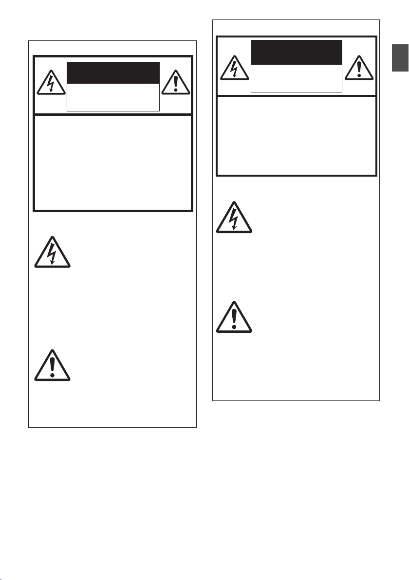
The lightning flash with
arrowhead symbol, within
an equilateral triangle is
intended to alert the user to
the presence of uninsulated
“dangerous voltage” within
the product’s enclosure that
may be of sufficient
magnitude to constitute a
risk of electric shock to
persons.
The exclamation point within
an equilateral triangle is
intended to alert the user to
the presence of important
operating and maintenance
(servicing) instructions in
the literature accompanying
the appliance.
RISK OF ELECTRIC
SHOCK
DO NOT OPEN
POUR CANADA
RISQUE
D’ELECTROCUTION
NE PAS OUVRIR
ATTENTION:
POUR EVITER TOUT RISQUE
D’ELECTROCUTION NE PAS
OUVRIR LE BOITER. AUCUNE
PIECE INTERIEURE N’EST A
REGLER PAR L’UTILISATEUR. SE
REFERER A UN AGENT QUALIFIE
EN CAS DE PROBLEME.
ATTENTION
Le symbole de l’éclair à
l’intérieur d’un triangle
équilatéral est destiné à
alerter l’utilisateur sur la
présence d’une “tension
dangereuse” non isolée dans
le boîtier du produit. Cette
tension est suffisante pour
provoquer l’électrocution de
personnes.
Le point d’exclamation à
l’intérieur d’un triangle
équilatéral est destiné à
alerter l’utilisateur sur la
présence d’opérations
d’entretien importantes au
sujet desquelles des
renseignements se trouvent
dans le manuel
d’instructions.
Ces symboles ne sont
utilisés qu’aux Etats-Unis.
.
Introduction
.
Safety Precautions
5
Page 6

Model Number:
Trade Name:
Responsible
party:
Address:
Telephone
Number:
Supplier's Declaration of Conformity
GY-HC550U
GY-HC500U
GY-HC500SPCU
JVC
JVCKENWOOD USA
Corporation
500 Valley Road,
Suite 203 Wayne,
NJ 07470
973-317-5000
This device complies with Part 15 of
the FCC Rules. Operation is subject to
the following two conditions: (1) This
device may not cause harmful
interference, and (2) this device must
accept any interference received,
including interference that may cause
undesired operation.
Changes or modifications not
approved by JVC could void the
user’s authority to operate the
equipment. This equipment has been
tested and found to comply with the
limits for a Class A digital device,
pursuant to Part 15 of the FCC Rules.
These limits are designed to provide
reasonable protection against harmful
interference when the equipment is
operated in a commercial
environment.
This equipment generates, uses, and
can radiate radio frequency energy
and, if not installed and used in
accordance with the instructions, may
cause harmful interference to radio
communications. Operation of this
equipment in a residential area is
likely to cause harmful interference in
which case the user will be required
to correct the interference at his own
expense.
Numéro de
modèle :
Nom de marque :
Personne
responsable :
Adresse :
Numéro de
téléphone :
Déclaration de conformité du fournisseur
GY-HC550U
GY-HC500U
GY-HC500SPCU
JVC
JVCKENWOOD USA
Corporation
500 Valley Road,
Suite 203 Wayne,
NJ 07470
973-317-5000
Cet ensemble se conforme à la partie 15 des
règles de la FCC (Federal Communications
Commission). Le fonctionnement est sujet aux
deux conditions suivantes : (1) Cet appareil ne
peut pas causer d’interférences nuisibles, et
(2) cet appareil doit accepter toute interférence
reçue, comprenant des interférences qui
peuvent causer un mauvais fonctionnement.
Des changements ou modifications
non approuvés par JVC peuvent
annuler le droit de l’utilisateur de faire
fonctionner l’appareil. Cet appareil a
été testé et il a été reconnu qu’il se
conforme aux limites concernant
l’appareillage informatique de classe
A correspondant à la partie 15 des
règles de la FCC. Ces limites sont
conçues pour fournir une protection
raisonnable contre les interférences
dangereuses lorsque l’équipement est
utilisé dans un environnement
commercial.
Cet appareil génère, utilise et peut
émettre de l’énergie des fréquences
radio et, s’il n’est pas installé et utilisé
selon les instructions du fabricant,
peut causer des interférences
nuisibles en communications radio.
L’utilisation de cet équipement dans
une zone résidentielle est susceptible
de causer des interférences néfastes,
auquel cas l’utilisateur devra prendre
des mesures à ses propres frais.
Introduction
.
.
6
Safety Precautions
.
.
Page 7

.
CAUTION:
The mains plug shall remain readily
operable.
Remove the mains plug immediately if
the camera functions abnormally.
WARNING:
The battery pack, the camera with
battery installed, and the remote control
with battery installed should not be
exposed to excessive heat such as direct
sunlight, fire or the like.
WARNING: TO PREVENT FIRE OR
SHOCK HAZARD, DO NOT
EXPOSE THIS UNIT TO RAIN OR
MOISTURE.
NOTES:
The rating plate and safety caution are
on the bottom and/or the back of the
main unit.
The serial number plate is on the
bottom of the unit.
The rating information and safety
caution of the AC adapter are on its
upper and lower sides.
Caution on Replaceable lithium
battery
The battery used in this device may
present a fire or chemical burn hazard if
mistreated.
Do not recharge, disassemble, heat
above 100°C (212°F) or incinerate.
Replace battery with Panasonic, Sanyo,
Sony or Maxell CR2025.
Danger of explosion or risk of fire if the
battery is incorrectly replaced.
Dispose of used battery promptly.
Keep away from children.
Do not disassemble and do not dispose
of in fire.
Attention:
La prise secteur doit être opérationnelle.
Débranchez immédiatement la fiche
secteur si le caméscope ne fonctionne
pas normalement.
Avertissement:
Évitez d’exposer la batterie, le
caméscope avec la batterie insérée ou la
télécommande avec la batterie insérée à
une chaleur excessive, telle que celle
des rayons directs du soleil, d’un feu ou
de tout autre source de chaleur.
AVERTISSEMENT : POUR EVITER
LES RISQUES D’INCENDIE OU
D’ELECTROCUTION, NE PAS
EXPOSER L’APPAREIL A LA
PLUIE NI A L’HUMIDITE.
REMARQUES :
La plaque d’identification et
l’avertissement de sécurité se trouvent
sous l’appareil et/ou au dos.
La plaque du numéro de série est
située sur la partie inférieure de
l’appareil.
Les informations d’identification et
l’avertissement de sécurité de
l’adaptateur secteur sont situés sur ses
côtés supérieur et inférieur.
Avertissement sur la pile au
lithium remplaçable
La pile utilisée dans cet appareil peut
présenter des risques d’incendie ou de
brûlure chimique si elle est mal traitée.
Ne pas recharger, démonter, chauffer à
plus de 100°C (212°F) ni mettre au feu.
Remplacez la pile avec Panasonic,
Sanyo, Sony ou Maxell CR2025.
Danger d’explosion ou risque d’incendie
si la pile n’est pas changée correctement.
Jeter immédiatement les piles usées.
Placer hors de la portée des enfants.
Ne pas démonter ni jeter au feu.
.
Introduction
.
.
.
.
.
.
.
.
Safety Precautions
7
Page 8

When the equipment is installed in a
cabinet or on a shelf, make sure that it
has sufficient space on all sides to allow
for ventilation (10 cm (3-15/16") or more
on both sides, on top and at the rear).
Do not block the ventilation holes.
(If the ventilation holes are blocked by a
newspaper, or cloth etc. the heat may not
be able to get out.)
No naked flame sources, such as lighted
candles, should be placed on the
apparatus.
When discarding batteries,
environmental problems must be
considered and the local rules or laws
governing the disposal of these batteries
must be followed strictly.
The apparatus shall not be exposed to
dripping or splashing and that no objects
filled with liquids, such as vases, shall be
placed on the apparatus.
Do not point the lens directly into the
sun. This can cause eye injuries, as well
as lead to the malfunctioning of internal
circuitry. There is also a risk of fire or
electric shock.
CAUTION!
The following notes concern possible
physical damage to this unit and to the
user.
Carrying or holding this unit by the LCD
monitor can result in dropping the unit,
or in a malfunction.
Do not use a tripod on unsteady or
unlevel surfaces. It could tip over,
causing serious damage to the unit.
CAUTION!
Connecting cables (Audio/Video, etc.) to
this unit and leaving it on top of the TV is
not recommended, as tripping on the
cables will cause the unit to fall, resulting
in damage.
Si le matériel est installé dans un coffret
ou sur une étagère, s’assurer qu’il y a un
espace suffisant sur tous les côtés pour
permettre la ventilation (10 cm (3-15/16")
ou plus sur les deux côtés, au dessus et
à l’arrière).
Ne pas boucher les orifices de
ventilation.
(Si les orifices de ventilation sont
bouchés par un journal, un tissu, etc., la
chaleur peut ne pas s’éliminer.)
Aucune source à flamme nue, telle que
des bougies allumées, ne doit être
placée sur l’appareil.
En jetant des batteries aux ordures, les
problèmes d’environnement doivent être
pris en considération et les
réglementations locales ou la législation
concernant le rebut de ces batteries
doivent être strictement respectées.
L’appareil ne doit pas être exposé à de
l’eau ou à des éclaboussures et les
objets remplis de liquide, tels que des
vases, ne doivent pas être placés sur
l’appareil.
Ne dirigez pas l’objectif directement vers
le soleil. Vous pourriez vous abîmer la
vue et l’appareil pourrait être
endommagé. Il y a aussi risque
d’incendie ou d’électrocution.
Attention!
Les remarques suivantes sont destinées
à protéger l’utilisateur et le caméscope
contre des dommages éventuels.
Ne pas transporter ou saisir le
caméscope par l’écran LCD, car il
pourrait tomber ou s’endommager.
Ne pas utiliser de trépied
photographique sur des surfaces
irrégulières et inclinées. Il pourrait
tomber et le caméscope pourrait être
sérieusement endommagé.
Attention!
Avec des câbles (Audio/Vidéo, etc.)
raccordés, il est recommandé de ne pas
laisser le caméscope sur le dessus du
téléviseur, car tirer sur les câbles
pourrait faire tomber le caméscope,
causant des dommages.
Introduction
.
.
.
Safety Precautions
8
.
.
.
Page 9
GY-HC550U
Radio Frequency Energy Safety Information
Warning
This JVC camera generates RF EME while
transmitting. RF
& Magnetic Energy) has the potential to cause
slight thermal, or heating effects to any part of
your body less than the recommended distance
from this radio transmitter’s antenna. RF energy
exposure is determined primarily by the distance
to and the power of the transmitting device. In
general, RF exposure is minimized when the
lowest possible power is used or transmission
time is kept to the minimum required for
consistent communications, and the greatest
distance possible from the antenna to the body
is maintained.
The following list provides you with the information
required to ensure that you are aware of RF
exposure.
While transmitting, always keep the antenna
0
and the radio at least 5 cm (1-31/32”) from your
body or face, as well as from any bystanders.
To maintain compliance with FCC's RF
0
exposure guidelines, use only the supplied
antenna (with antenna holder).
Unauthrized antenna, modification, or
attachments could damage the transmitter and
may violate FCC regulations.
Electromagnetic Interference Compatibility
Electronic devices are susceptible to
electromagnetic interference (EMI) if they are not
adequately shielded or designed for
electromagnetic compatibility.
Because this product generates RF energy, it can
cause interference to such equipment.
Turn OFF
0
do so. Hospitals and health care facilities use
equipment that is sensitive to electromagnetic
radiation.
Turn OFF your product while on board an aircraft
0
when so instructed. Use of the product must be
in accordance with airline regulations and/or
crew instructions.
EME (Radio Frequency Electric
your WLAN where signs are posted to
Informations sur la sécurité en présence
d'énergie par radiofréquences
Avertissement
caméscope
Ce
de la transmission. L'EME par RF (énergie
électrique et magnétique par radiofréquences)
peut causer de légers effets thermiques ou
chauffants sur toute partie de votre corps,
lorsque vous trouvez à une distance inférieure à
celle recommandée de l’antenne de cet émetteur
radio. L'exposition à l'énergie par
radiofréquences est principalement déterminée
par la distance et la puissance de l'appareil
émetteur. En général, l'exposition aux
radiofréquences est minimisée lorsqu'on utilise
la puissance la plus faible possible ou que le
temps de transmission est maintenu au minimum
requis pour assurer des communications
cohérentes et lorsqu'on maintient la plus grande
distance possible entre l'antenne et le corps.
La liste suivante vous fournit les informations dont
vous avez besoin pour être sûr d'être informé de
l'exposition aux radiofréquences.
Pendant la transmission, gardez toujours
0
l’antenne et
de votre corps ou de votre visage, ainsi que de
toutes les personnes aux alentours.
Pour maintenir la conformité avec les directives
0
d’exposition RF de la FCC, utilisez uniquement
l’antenne fournie (avec support d'antenne).
Une antenne, une modification ou des
accessoires non autorisés peuvent
endommager le transmetteur et enfreindre les
réglementations de la FCC.
Compatibilité aux interférences
électromagnétiques
Les appareils électroniques sont sensibles aux
interférences électromagnétiques (EMI) s'ils ne
sont pas correctement protégés ou conçus pour
une compatibilité électromagnétique.
Étant donné que cet appareil génère de l’énergie
par radiofréquences, il peut provoquer des
interférences avec ce genre d’équipement.
Éteignez votre WLAN lorsque des signes vous
0
l'indiquant s'affichent. Les hôpitaux et les
établissements de santé utilisent un
équipement sensible aux rayonnements
électromagnétiques.
Éteignez votre appareil lorsque vous trouvez à
0
bord d’un avion et qu'on vous le demande.
L'utilisation de l'appareil doit être conforme aux
règlements de
instructions de l'équipage.
JVC génère de l'EME par RF lors
la radio à au moins 5 cm (1-31/32”)
la compagnie aérienne et/ou aux
Introduction
Safety Precautions
9
Page 10
GY-HC550U
For indoor use only (5150-5250 MHz) in
Canada
There are legal restrictions on the use and
outdoor use depending on the country and
region. Please be careful not to violate the law.
Introduction
Pour usage intérieur seulement (5150-5250
MHz) au Canada
Il existe des restrictions légales concernant
l’utilisation générale et extérieure en fonction du
pays et de la région. Veillez à respecter la loi.
Data transmission is always intiated by software,
which is the passed down through the MAC,
through the digital and analog baseband, and
the RF chip. Several special packets are
finally to
initiated by the MAC.These are the only ways the
digital baseband portion will turn on the RF
transmitter, which it then turns off at the end of
the packet. Therefore, the transmitter will be on
only while one of the aforementioned packets is
being transmitted.In other words, this device
automatically discontinue transmission in case
of either absence of information to transmit or
operational failure.
Frequency Tolerance: 20 ppm
This radio transmitter (6549A-W8997M1216)
has been approved by Innovation, Science and
Economic Development
the antenna types listed bellow, with the
maximum permissible gain indicated.
Antenna types not included in this list that have
a gain greater than the maximum gain indicated
for any type listed are strictly prohibited use with
this device.
Antenna
type
Dipole
3.6 dBi (4.9-5.8 GHz)
1.9 dBi (2.4-2.5 GHz)
Canada to operate with
Gain Impedance
50 Ω
La transmission des données est toujours initiée
logiciel, puis les données sont transmises
par le
par l'intermédiaire du MAC, par la bande de base
numérique et analogique et, enfin à la puce RF.
Plusieurs paquets spéciaux sont initiés par le
MAC. Ce sont les seuls moyens pour qu'une de
la bande de base numérique active l'émetteur
RF, puis désactive celui-ci à la fin du paquet. En
conséquence, l'émetteur reste uniquement
activé lors de la transmission d'un des paquets
susmentionnés. En d'autres termes, ce dispositif
interrompt automatiquement toute transmission
en cas d'absence d'informations à transmettre
ou de défaillance.
Tolérance de fréquence: 20 ppm
Le présent émetteur radio (6549 A-W 8997 M
1216) a été approuvé par Innovation, Sciences
et Développement économique Canada pour
fonctionner avec les types d'antenne énumérés
ci-dessous et
Les types d'antenne non inclus dans cette liste,
et dont le gain est supérieur au gain maximal
indiqué pour tout type figurant sur la liste, sont
strictement interdits pour l'exploitation de
l'émetteur.
Types
d'antenne
Dipôle
ayant un gain admissible maximal.
Gain l'impédance
3.6 dBi (4.9-5.8 GHz)
1.9 dBi (2.4-2.5 GHz)
50 Ω
Safety Precautions
10
Page 11

GY-HC550U
This transmitter must not be co-located or
operated in conjunction with any other antenna
or transmitter.
Cet émetteur ne doit pas être co-localisé ou
utilisé en conjonction avec une autre antenne ou
un autre émetteur.
This device contains licence-exempt
transmitter(s)/receiver(s) that comply with
Innovation, Science and Economic
Development Canada’s
Operation is subject to the following two
conditions:
This device may not cause interference.
A
This device must accept any interference,
B
including interference that may cause
undesired operation of the device.
The available scientific evidence does not show
that any health problems are associated with
using low power wireless devices. There is no
proof, however, that these low power wireless
devices are
devices emit low levels of radio frequency energy
(RF) in the microwave range while being used.
Whereas high levels of RF can produce health
effects (by heating tissue), exposure of low-level
RF that does not produce heating effects causes
no known adverse health effects. Many studies
of low-level RF exposures have not found any
biological effects. Some studies have suggested
that some biological effects might occur, but
such findings have not been confirmed by
additional research.
The RF module, W8997-M1216 has been tested
and found to comply with FCC/ISED radiation
exposure limits set forth for an uncontrolled
environment and meets the FCC radio frequency
(RF) Exposure Guidelines and RSS-102 of the
ISED radio frequency (RF) Exposure rules.
absolutely safe. Low power Wireless
licence-exempt RSS(s).
L’émetteur/récepteur exempt de licence contenu
dans le présent appareil est conforme aux CNR
d’Innovation, Sciences et Développement
économique Canada applicables aux appareils
radio exempts de licence. L’exploitation est
autorisée aux deux conditions suivantes :
L’appareil ne doit pas produire de brouillage;
A
L’appareil doit accepter tout brouillage
B
radioélectrique
susceptible d’en compromettre le
fonctionnement.
Les connaissances scientifiques dont nous
disposons n’ont mis en évidence aucun
problème de santé associé à l’usage des
appareils sans fil à faible puissance. Nous ne
sommes cependant pas en mesure de prouver
que ces
appareils sans fil à faible puissance sont
entièrement sans danger. Les appareils sans fil
à faible puissance émettent une énergie
fréquence radioélectrique (RF) très faible dans
le spectre des micro-ondes lorsqu’ils sont
utilisés. Alors qu’une dose élevée de RF peut
avoir des effets sur la santé (en chauffant les
tissus), l’exposition à de faibles RF qui ne
produisent pas de chaleur n’a pas de mauvais
effets connus sur la santé. De nombreuses
études ont été menées sur les expositions aux
RF faibles et n’ont découvert aucun effet
biologique. Certaines études ont suggéré qu’il
pouvait y avoir certains effets biologiques, mais
ces résultats n’ont pas été confirmés par des
recherches supplémentaires.
Le module RF, W8997-M1216 a été testé et jugé
conforme aux limites d’exposition aux
rayonnements énoncées pour un
environnement non contrôlé et respecte les
règles les radioélectriques (RF) de la FCC lignes
directrices d'exposition et d’exposition aux
fréquences radioélectriques (RF) CNR-102 de l’
ISDE.
même si le brouillage est
subi,
Introduction
Safety Precautions
11
Page 12
IMPORTANT (for owners in the U.K.)
Connection to the mains supply in
the United Kingdom.
DO NOT cut off the mains plug from
this equipment.
If the plug fitted is not suitable for the
power points in your home or the cable is
too short to reach a power point, then
obtain an appropriate safety approved
extension lead or contact the local
dealers in your area.
BE SURE to replace the fuse only with
an identical approved type, as originally
fitted, and to replace the fuse cover.
If nonetheless the mains plug is cut off
be sure to remove the fuse and dispose
of the plug immediately, to avoid possible
shock hazard by inadvertent connection
to the mains supply.
If this product is not supplied fitted with a
mains plug then follow the instructions
given below:
DO NOT make any connection to the
Larger Terminal coded E or Green.
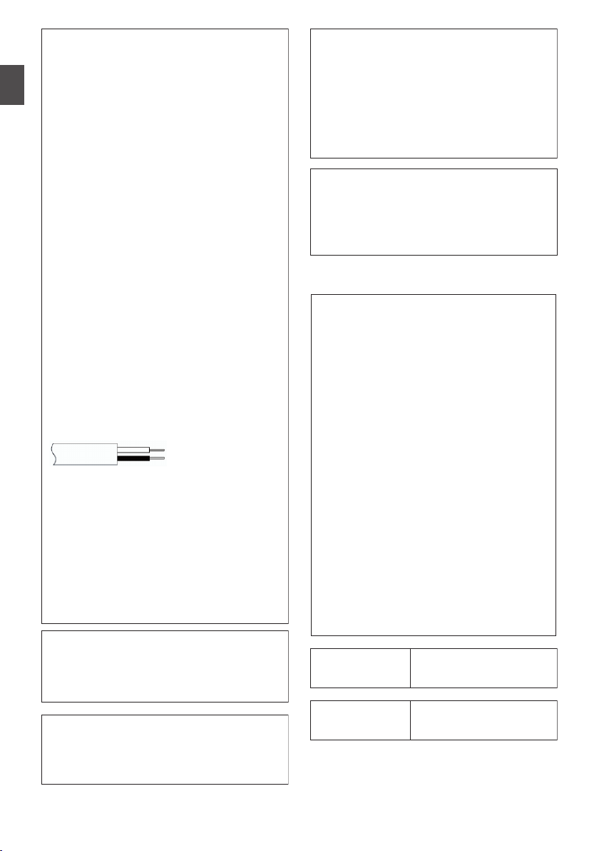
The wires in the mains lead are coloured
in accordance with the following code:
If these colours do not correspond with
the terminal identifications of your plug,
connect as follows:
Blue wire to terminal coded N (Neutral)
or coloured black.
Brown wire to terminal coded L (Live) or
coloured Red.
If in doubt — consult a competent
electrician.
CAUTIONS:
To prevent shock, do not open the cabinet.
No user serviceable parts inside.
Refer servicing to qualified personnel.
Blue to N
(Neutral) or Black
Brown to L (Live)
or Red
WARNING
Operation of this equipment in a
residential environment could cause
radio interference.
CAUTION:
Where there are strong electromagnetic
waves or magnetism, for example near a
radio or TV transmitter, transformer,
motor, etc., the picture and the sound
may be disturbed. In such case, please
keep the apparatus away from the
sources of the disturbance.
The plastics packaging bags may cause
suffocation when they are covered over the
head. Tear them open, and keep them away
from the reach of infants and children by
ensuring that they are disposed of properly.
Wireless LAN
This device is a 2.4 GHz wideband
transmission system (transceiver),
intended for use in all EU member
states and EFTA countries, except in
France and Italy where restrictive use
applies.
In Italy the end-user should apply for a
license at the national spectrum
authorities in order to obtain
authorization to use the device for
setting up outdoor radio links and/or for
supplying public access to
telecommunications and/or network
services.
This device may not be used for setting
up outdoor radio links in France and in
some areas the RF output power may
be limited to 10 mW EIRP in the
frequency range of 2454 - 2483.5 MHz.
For detailed information the end-user
should contact the national spectrum
authority in France.
Frequency Range
Output Power
2.4GHz Band : 1 - 13ch
11 b/g/n : 14 dBm
(max)
Frequency Range
Output Power
5GHz Band : W52/W53/W56
11 n/a/ac : 11 dBm (max)
Introduction
.
.
Safety Precautions
12
.
.
GY-HC550E
.
.
.
Page 13
GY-HC550E and GY-HC500E
The European representative of
JVCKENWOOD Corporation is:
Die europäische Vertretung für die
JVCKENWOOD Corporation ist:
JVCKENWOOD Deutschland GmbH
Konrad-Adenauer-Allee 1-11
61118 Bad Vilbel
GERMANY
Dear customer,
this apparatus is in compliance with the
valid European Directive and the
relevant standards regarding
electromagnetic compatibility.
Sehr geehrter Kunde, sehr geehrte
Kundin,
dieses Gerät stimmt mit der gültigen
europäischen Richtlinie und den
relevanten Normen bezüglich
elektromagnetischer Verträglichkeit
überein.
Hereby, JVCKENWOOD Corporation
declares that the radio equipment type
GY-HC550E is in compliance with
Directive 2014/53/EU.
The full text of the EU declaration of
conformity is available at the following
internet address:
Hiermit erklärt die, JVCKENWOOD
Corporation, dass der Funkanlagentyp
GY-HC550E der Richtlinie 2014/53/EU
entspricht.
Der vollständige Text der
EU-Konformitätserklärung ist unter der
folgenden Internetadresse verfügbar:
http://www3.jvckenwood.com/ecdoc/
Battery Pack
The supplied battery pack is a lithium-ion
battery. Before using the supplied battery
pack or an optional battery pack, be sure
to read the following cautions:
To avoid hazards
... do not burn.
When transporting, carry the battery in
a plastic bag.
... do not modify or disassemble.
... do not expose the battery to
temperatures exceeding 60°C (140°F),
as this may cause the battery to
overheat, explode or catch fire.
... use only specified chargers.
To prevent damage and prolong
service life
... do not subject to unnecessary shock.
... charge within the temperature range
of 10°C to 35°C (50°F to 95°F). Cooler
temperatures require longer charging
time, or in some cases stop charging
at all. Warmer temperatures prevent
complete charging, or in some cases
stop charging at all.
... store in a cool, dry place. Extended
exposure to high temperatures will
increase natural discharge and
shorten service life.
... keep a 30% battery level if the
battery pack is not to be used for a
long period of time.
... remove from charger or powered unit
when not in use, as some machines
use current even when switched off.
... do not drop or subject to strong
impact.
... do not short-circuit the
terminals. Keep it away
from metallic objects
when not in use.
Terminals
.
GY-HC500E
.
GY-HC550E
.
Introduction
.
Safety Precautions
13
Page 14
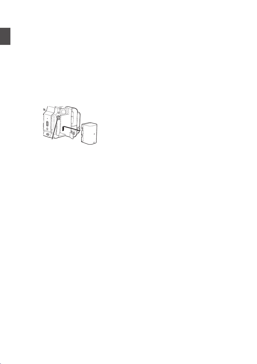
Para Brasil
Informação sobre eliminação de
baterias
Este produto não deverá ser eliminado
como lixo doméstico em geral.
Devolva a bateria velha ao comerciante
ou para a rede autorizada, para que seja
devolvida ao fabricante ou importador.
A reciclagem e eliminação de lixo em
uma maneira adequada, ajudarão para
preservar recursos, prevenindo, ao
mesmo tempo, contra efeitos prejudiciais
sobre a nossa saúde e o meio ambiente.
o
Empurre
Introduction
.
.
Safety Precautions
14
Page 15

Contents
Introduction
Safety Precautions ............................................
Contents .......................................................... 15
Main Features ................................................. 18
Precautions for Proper Use ............................. 20
Operation Modes ............................................. 24
Names of Parts ................................................ 26
Side Control Panel ....................................... 28
Rear Terminal .............................................. 30
LCD Monitor ................................................ 31
Lens Section ................................................ 31
Basic System Diagram .................................... 32
Preparations
Settings and Adjustments Before Use ............. 33
Adjusting the Grip Belt ................................. 33
Attaching the External Microphone (Sold
Separately) .................................................. 33
Opening/Closing the Lens Cover ................. 33
Attaching the Tripod (Sold Separately) ........ 33
Attaching the Wireless LAN Antennas
(Supplied) A ............................................ 34
Attaching/Detaching the Hood ..................... 34
Power Supply .................................................. 35
Using a Battery Pack .................................... 35
Using AC Power (DC IN Power) ................... 36
Power Status Display ...................................... 37
Turning On/Off the Power ................................ 38
Initial Settings .................................................. 39
Displays on the LCD Monitor and Viewfinder .. 41
Display Screen ............................................. 41
Status Screen .............................................. 42
Remote Edit Mode Screen ........................... 42
Warning Display ........................................... 42
Adjusting the LCD Monitor and Viewfinder ...... 43
Adjusting the LCD Monitor ........................... 43
Adjusting the Viewfinder .............................. 44
Assignment of Functions to User Buttons ........ 46
Tally Lamp and LED ........................................ 47
Recording Media ............................................. 48
Usable Cards ............................................... 48
Usable SSD Media ...................................... 48
Estimated Recordable Time of SD Cards .... 48
Estimated Recordable Time of SSD Media .. 49
Inserting an SD Card .................................... 50
Removing the SD Card ................................ 50
Switching the SD cards ................................ 51
Inserting the SSD Media Adapter ................. 51
Formatting (Initializing) of Recording Media . 51
Repairing the Recording Media ................... 52
Clips Recorded to Recording Media ............ 53
About the Operation Lock Feature (KEYLOCK)
.........................................................................
Shooting
5
Basic Shooting Procedures ............................. 55
Selecting System Definition, File Format and Video
Format ............................................................. 56
Zoom Operation .............................................. 59
Focus Operation .............................................. 60
Adjusting the Focusing by Face Detection ...... 62
Adjusting the Brightness .................................. 64
Adjusting the Iris .............................................. 65
Setting the Gain ............................................... 66
Setting the Electronic Shutter .......................... 67
Setting the ND Filter ........................................ 68
Adjusting the White Balance ............................ 69
Adjusting the Camera Image ........................... 73
Using the Image Stabilizer ............................... 73
Audio Recording .............................................. 74
Monitoring Audio Sound During Recording Using a
Headphone ...................................................... 76
Time Code and User’s Bit ................................ 76
Setting Time Code Generator .......................... 77
Setting the User’s Bit ....................................... 80
Synchronizing Time Code on Another Camera
......................................................................... 81
Setting Zebra Pattern ...................................... 82
Setting Spot Meter ........................................... 83
Acquiring Positioning Information by GPS A
L ................................................................. 85
Viewing Recorded Videos Immediately (Clip
Review) ........................................................... 86
Displaying the Histogram ................................ 87
Recording Simultaneously at Two Different
Definitions ....................................................... 87
Series Rec ....................................................... 87
Dual Rec .......................................................... 88
Backup Rec ..................................................... 89
Special Recording ........................................... 91
Pre Rec ........................................................ 91
Clip Continuous Rec .................................... 92
Frame Rec ................................................... 94
Interval Rec .................................................. 95
Splitting the Clips Freely (Clip Cutter Trig) ....... 96
Configuring Infrared Recording ....................... 96
54
Introduction
Contents
15
Page 16

Playback
Playing Recorded Clips
Thumbnail Screen ........................................ 97
Actions ......................................................... 99
Playing back .............................................. 100
Deleting Clips ................................................ 102
Introduction
Appending/Deleting OK Mark ........................ 103
Selecting and Performing Operations on Multiple
Clips .............................................................. 104
Selecting Multiple Clips Randomly ............. 104
Selecting Multiple Clips Consecutively ...... 105
Trimming Recorded Clips .............................. 106
...................................
Menu Display and Detailed Settings
Basic Operations in Menu Screen ................. 107
Display and Description of the Menu Screen
................................................................... 108
Text Input with Software Keyboard ............ 109
Menu Screen Hierarchical Chart ................... 110
Camera Function Menu ................................. 111
Zoom Function Settings ............................. 113
Focus Function Settings ............................ 115
Face Detection Function Settings .............. 116
User Switch Set Item .................................. 116
Camera Process Menu .................................. 119
White Balance Item .................................... 124
TC/UB Menu ................................................. 125
LCD/VF Menu ................................................ 127
Shooting Assist Item .................................. 128
Marker Settings Item .................................. 129
Display Type Item ...................................... 130
Display On/Off Item .................................... 131
A/V Set Menu ................................................ 132
Video Set Item ........................................... 132
Audio Set Item ........................................... 135
Network Menu ............................................... 138
Connection Setup Item .............................. 139
Live Streaming Item ................................... 140
Return over IP Item .................................... 145
Web Item ................................................... 147
Metadata Server Item ................................ 148
Upload Settings Item .................................. 148
Overlay Settings Menu A L .................. 151
Settings Item L (Sportzcast) .................. 153
System Menu ................................................ 154
Record Set Item ......................................... 156
Adding/Editing Frequently Used Menu Items
(Favorites Menu) ........................................... 162
Adding Menu Items to Favorites Menu ...... 162
Editing Favorites Menu .............................. 163
Display/Status Screen
Display Screen in Camera Mode
97
Display Screen in Media Mode ...................... 172
Status Screen ................................................ 174
................... 166
Camera Features
Marker and Safety Zone Displays (Camera Mode
Only) .............................................................. 176
Color Bar Output ........................................... 176
Adjusting the Gamma .................................... 177
Adjusting Color Matrix ................................... 178
Configuring Setup Files ................................. 179
Saving Setup Files ..................................... 180
Loading a Setup File .................................. 181
Deleting Setup Files ................................... 181
Connecting External Devices
Connecting External Monitor ......................... 182
Connect the headphone ................................ 183
Connecting Wired Remote Control ................ 183
Network
Functions of Network Connection .................. 184
Preparing Network Connection ...................... 185
Operating Environment .............................. 185
Camera Setup for Network Connection ..... 185
Connecting to the Network ............................ 186
Importing Metadata ....................................... 187
Preparing Metadata ................................... 187
Configuring the Server for Downloading .... 188
Importing Metadata .................................... 188
Uploading a Recorded Video Clip ................. 189
Configuring the FTP Server for Uploading . 189
Uploading Clips Automatically (Auto FTP) . 190
Automatic Chunked Upload to FTP Server 190
Uploading Clips Manually (Manual FTP) .... 191
FTP Resume Feature .................................... 193
Connecting from a Web Browser ................... 194
Editing Metadata ........................................... 195
Planning Metadata ..................................... 195
Clip Metadata ............................................ 196
Uploading a Recording Clip via a Web Browser
....................................................................... 198
View Remote Feature .................................... 202
Operating Procedure ................................. 202
Registering/Deleting Preset Zoom ............. 203
Camera Control Function .............................. 204
16
Contents
Page 17

Changing the Settings via a Web Browser .... 206
Changing View Remote Function Settings . 207
Changing Connection Setup ......................
207
Changing Metadata Server Settings .......... 208
Changing Clip Server Settings ................... 208
Changing Streaming Settings .................... 208
Managing the Network Connection Settings File
....................................................................... 209
Saving the Connection Settings File .......... 209
Reading the Connection Settings File ........ 210
Deleting Connection Settings .................... 211
Performing Live Streaming ............................ 212
Setting Distribution ..................................... 216
Starting Distribution ................................... 219
Setting the FEC Matrix ............................... 220
Logging in to Facebook ................................. 221
Preliminary Configuration ........................... 221
Connection Setup ...................................... 221
Live Streaming on Facebook Live ................. 222
Live Streaming ........................................... 222
Logging in to YouTube .................................. 223
Preliminary Configuration ........................... 223
Connection Setup ...................................... 224
Live Streaming on YouTube Live ................... 225
Live Streaming ........................................... 225
Return Video/Audio from the Network (Return over
IP) .................................................................. 227
IFB (Return Audio) ......................................... 228
Tagging Feature L .................................... 229
Configuring to Exchange Format ............... 229
Configuring Camera Angle Information ...... 229
Entering Tag Information ............................ 229
Synchronizing GPS Time Code ................. 230
Overlay A L
Broadcast Overlay A L ......................... 231
Importing and Configuring Settings for SDP Files
for Broadcast ............................................. 231
Displaying Watermark Images ................... 233
Displaying Images on the Whole Screen (Full
Screen Graphic Function) .......................... 233
Protecting Overlay Settings with a Password
................................................................... 235
Specifying Text and Images ....................... 236
Scoreboard Overlay L .............................. 236
Configuring Scoreboard Display ................ 236
Configuring Scoreboard Display Position .. 237
Entering Scoreboard Data ......................... 238
Team Display Settings ............................... 245
Entering Scoreboard Data Automatically ... 246
Others
Error Messages and Actions .........................
List of FTP Transfer Errors .........................
List of Live Streaming Error Displays ......... 251
List of Layout Import Error Displays A L
................................................................... 252
List of Sportzcast Connection Error Displays
L ............................................................ 252
Blinking of the Tally Lamp .......................... 253
Warning Tone ............................................ 253
Troubleshooting ............................................ 254
Specifications ................................................ 256
Appendix ....................................................... 262
Index ............................................................. 263
Software License Agreement ........................ 265
Important Notice concerning the Software ..... 266
.
248
249
Introduction
Contents
17
Page 18

Main Features
1" CMOS sensor and new 4K 20x lens
for high-quality recording
Introduction
Comes with a 1" CMOS sensor that delivers high
resolution and an excellent S/N ratio. At the same
time, a new 4K 20x lens with a good balance in
viewing angle, image quality and magnification is
employed to
thereby achieving premium-quality 4K recording
with high sensitivity and low noise.
“Apple ProRes 422” available as a
standard feature to achieve highresolution and high bit-rate recording
performance
By making use of the “KA-MC100” SSD Media
Adapter (sold separately), it is possible to perform
4K 50p/60p
speed SSD memory.
A variety of wired and wireless
interfaces to support various network
connections
In addition to the USB host terminal for wireless
LAN and LTE USB adapter connections, this
camera recorder is equipped with a variety of
interfaces such as wired LAN terminal and built-in
wireless LAN
antennas A to support various network
connections.
reduce the occurrence of aberrations,
Apple ProRes 422 recording to a high-
with 2.4GHz/5GHz MIMO dual band
HDR and log gamma for high dynamic
range and wide color gamut
This camera recorder is equipped with HLG
(Hybrid Log-Gamma) that conforms to ITU-BT.
2100 and our in-house J-Log1 Gamma with 800%
dynamic range to cope with HDR (High Dynamic
Range). Capable of recording in 10-bit for high
dynamic range and wide color gamut.
High-frame-rate recording in Full HD
quality (1920x1080)
Videos with a maximum frame rate of 120 fps can
be recorded
the style of the subject in fast-moving sports and in
video expression that leaves a deep impression.
in slow motion. It can be used to check
Broadcast Overlay A L
Station name, program name, or news title
according to the recorded content can be entered
easily by using a smartphone or tablet, and this
information can
clip or streaming images.
Also, it comes with a full-screen graphic feature that
allows overlay of the entire screen with images
such as notifications and advertisements.
be superimposed on the recording
Score Board Overlay L
Allows display of scores for games such as football,
baseball, basketball and hockey over the video
image.
can
Scores
while video-shooting is in progress, enabling easy
operation such as live broadcast by a small crew.
be entered from a smartphone or tablet
Bidirectional live streaming feature
Enables live streaming broadcast from the camera,
while at the same time receives program images
from studio stations as IP return video or intercom
audio as IP return audio (IFB) over the same line.
High quality
signal processing by 10-bit,
4:2:2 sampling
High quality signal processing that delivers rich
gradation expression and color reproduction of
video signals is possible by means of 10-bit, 4:2:2
sampling.
Various
Recording codecs supported are MPEG-4 AVC/H.
264 and Apple ProRes 422, which is compatible
with 4:2:2 10-bit recording. Selectable ProRes
formats include Apple ProRes 422HQ, Apple
ProRes 422 and Apple ProRes 422LT. Selectable
MPEG-4 AVC/H.264 formats include QuickTime
(MOV) and MP4.
It is also compatible with MPEG2 MXF, which is a
widely-used format at broadcasting stations. A
18
usage-based
Main Features
recording formats
Auto focus/optical image stabilizer
(OIS)
The camera recorder is equipped with a face
detection auto
screen. Switching to manual focus is also possible.
A built-in optical image stabilizer feature is also
available.
focus function that covers the entire
Prevents camera shake with the OIS
hard lock feature
Helps to secure the OIS lens to prevent unnatural
video images due to sudden acceleration of
vehicles when
the camera is mounted on a vehicle.
Page 19

Double SD card slots for series/dual
recordings
The most common SDHC/SDXC card recording
system is used for the memory card. This ensures
high reliability and operation at low running cost.
Various user friendly recording options are
available. These include series recording which
enables seamless long hour continuous
recordings over
same file to two slots.
the slots and dual recording of the
FTP feature that supports automatic
upload
Clips stored in the recording media can be
automatically uploaded to the FTP server while
recording is in progress. Also, FTP transfer
continues without stopping during live streaming
and Return over IP
Large tricolor LED indicators that show
the camera and network status
The two large LED indicators light up in three
different colors
status and network status (including the return
video) at a glance.
to allow identification of the camera
Time code input/output terminals for
shooting using multiple cameras
This camera recorder supports the use of multiple
cameras as well as studio use.
Professional-style switch layout and
diverse video parameters
Switches for Gain and White Balance are available
on the side panel to enable quick switching
according to the shooting scene. Image quality
parameters such as gamma and color matrix are
also available in the menu for adjustment to the
preferred tones.
Built-in GPS A L
This camera recorder is built in with GPS function,
which enables the positional information obtained
from the GPS satellite during a shoot to be
recorded as metadata.
* Note that acquisition of the positional
information may fail depending on the weather
condition.
User buttons/switches assignable with
different functions for greater ease of
use
Menu items corresponding to each user button are
available to assign the buttons with different
functions.
Symbols used
Caution : Describes precautions concerning the
Memo : Describes reference information, such
A
A
B
L
Content of this manual
All rights reserved by JVCKENWOOD
0
Corporation. Unauthorized duplication or
reprinting of this manual, in whole or in part, is
strictly prohibited.
Illustrated designs, specifications and other
0
contents of this manual are subject to change for
improvement without prior notice.
SDXC and SDHC logos are trademarks of
0
SD-3C, LLC.
The terms HDMI and HDMI High-Definition
0
Multimedia Interface, and the HDMI Logo are
trademarks or registered trademarks of HDMI
Licensing Administrator, Inc. in the United States
and other countries.
QuickTime, Final Cut Pro, Finder, iPhone, iPad,
0
iPod touch, macOS and Safari are registered
trademarks of Apple Inc. in the U.S. and other
countries.
iOS is a trademark or registered trademark of
0
Cisco in the U.S. and other countries and is used
under license.
Android, YouTube, the “YouTube logo” and
0
Google Chrome are trademarks and registered
trademarks of Google LLC.
“Facebook” and the “Facebook” logo are
0
trademarks and registered trademarks of
Facebook, Inc.
QR Code is a registered trademark of Denso
0
Wave Incorporated.
Microsoft and Windows are registered
0
trademarks of U.S.-based Microsoft Corporation
in the U.S. and other countries.
The company name of Fontworks, Fontworks,
0
and the name of the fonts are registered
trademarks of Fontworks Inc.
Zixi and the Zixi logo are trademarks of Zixi LLC.
0
Other product and company names included in
0
this instruction manual are trademarks and/or
registered trademarks of their respective
companies. Marks such as ™ and ® have been
omitted in this manual.
Descriptions in this manual are based on firmware
version V0220.
operation of this product.
as functions and usage restrictions of
this product.
: Indicates the reference page numbers
and reference items.
: Feature available on GY-HC550U/
GY-HC550E only.
: Feature available on GY-HC500U/
GY-HC500E/GY-HC500SPCU only.
: Feature available on GY-HC500SPCU
only.
Introduction
Main Features
19
Page 20

Precautions for Proper Use
Power Saving
o
When this unit is not in use, be sure to set the
[POWER ON/OFF] switch to “OFF” in order to
reduce power consumption.
Storage and Usage Locations
Introduction
o
Allowable ambient temperature and humidity
Be sure to use this unit within the allowable
temperature range of 0 °C to 40 °C (32 °F to
104°F) and a relative humidity of 30 % to 80 %.
Using this unit at a temperature or humidity
outside the allowable ranges could result not
only in malfunction but also serious impact on
the CMOS elements as small white spots may
generated.
be
o
Strong electromagnetic waves or magnetism
Noise may appear in the picture or audio and/or
the colors may be incorrect if this unit is used
near a radio or television transmitting antenna,
in places where strong magnetic fields are
generated by transformers, motors, etc., or near
devices emitting radio waves, such as
transceivers or cellular phones.
o
Use of wireless microphone near this unit
When a wireless microphone or wireless
microphone tuner is used near this unit during
recording, the tuner could pick up noise.
o
Avoid using or placing this unit in the following
places.
Places subject to extreme heat or cold
0
Places with excessive dirt or dust
0
Places with high humidity or moisture
0
Places subject
0
a cooking stove
Places subject to strong vibrations or unstable
0
surfaces
In a parked car under direct sunlight or near a
0
heater for long hours
o
Do not place this unit at places that are subject
to radiation
occur.
o
Protect this unit from being splashed with water.
(Especially when shooting in the rain)
o
Protect this unit from getting wet when shooting
on a beach. In addition, salt and sand may
adhere to the body. Be sure to clean the unit after
use.
o
Protect this unit against penetration of dust
when using it in a place subject to sandy dust.
Please exercise care during use.
to smoke or vapor such as near
or X-rays, or where corrosive gases
Maintenance
o
Turn off the power before performing any
maintenance.
o
Wipe the external cabinet of the unit with a soft
cloth. Do not wipe the body with benzene or
thinner. Doing
or turn cloudy. When it is extremely dirty, soak
the cloth in a solution of neutral detergent, wipe
the body with it, and then use a clean cloth to
remove the detergent.
so may cause the surface to melt
Rechargeable Battery
o
Be sure to use only the specified batteries.
We do not guarantee the safety and
performance of this device if an unspecified
battery is used.
o
Store the battery in a cool and dry place when
not in use. Do not expose the battery to high
temperatures (such as in a car under direct
sunlight). Failure to do so not only shortens the
battery life but also damages the battery.
o
Charge the battery first before using.
o
If you are not using the battery for a prolonged
of
period
30 % to 40 % charge level to prevent
deterioration.
o
Recharge the battery to a level of 10 % to 20 %
once every six months when storing the battery.
Storing the battery at a fully discharged state will
result in over discharging and inability to charge
the battery.
o
ATTENTION:
time, remove and keep the battery at a
The product you have purchased
is powered by a rechargeable
battery that is recyclable.
call
Please
information on how to recycle this
battery.
1-800-8-BATTERY for
Carrying the Camera
o
20
drop or hit this unit against a hard object
Do not
when transporting.
Precautions for Proper Use
Page 21

Regular Inspection (Maintenance)
Groove
o
Under normal environment, dust will
accumulate on the camera recorder when it is
used over a long period. Dust may enter the
camera recorder especially if it is used outdoors.
This may affect the image and sound quality of
the camera recorder. Check and replace the fan
after every 9000 hours (suggested guideline).
You can check the usage time of the fan in
[System] B [System Information] B [Fan Hour].
A P156 [ Fan Hour ] )
(
If the fan is used for more than 9000 hours
without replacement, “Fan Maintenance
Required” will be displayed every time you turn
on the power.
SDHC/SDXC Cards
o
SDHC/SDXC card
“recording media” in this manual.
o
This camera recorder saves the recorded
images and audio sound on the SD card (sold
separately) in the card slot.
o
If the SD card contains files recorded by devices
other than this camera recorder or files that are
saved from a PC, the recordable time may be
shorter or data may not be properly recorded. In
addition, the remaining space on the card may
not increase even when files are deleted using
a PC.
o
For details on the combinations of usable SD
card and format setting, refer to the following.
(A P48 [Format Setting and Usable SD Card
Combinations] )
Using cards other than those from Panasonic,
*
TOSHIBA or SanDisk may result in recording
failure or data loss.
is referred to as “SD card” or
Handling of SD Cards
o
The status indicator lights up in red when data
on the SD card is being accessed.
Do not remove the SD card during data access
(such as
not turn off the power or remove the battery and
AC adapter during access either.
o
Do not use or store the SD card in a place that
is subject to static electricity or electrical noise.
o
Do not
exposed to strong magnetic fields or radio
waves.
o
Inserting the SD card incorrectly may result in
damage of this unit or the SD card.
o
We are not liable for any accidental loss of data
stored on the SD card. Please back up any
important data.
recording, playback, or formatting). Do
place the SD card near locations that are
o
Make use of the SD card within the prescribed
conditions of use.
Do not use it at the following locations.
Places that are subject to direct sunlight, high
humidity or corrosion, places near thermal
equipment, sandy or dusty places, or in a car
under the sun with the doors and windows
closed.
o
o
o
o
o
o
o
o
o
o
o
o
bend or drop the SD card, or subject it to
Do not
strong impact or vibration.
Do not splash the SD card with water.
Do not dismantle or modify the SD card.
Do not touch the terminals with your hands or
with a metal object.
Do not allow dust, dirt, water, or foreign objects
to adhere to the terminals.
remove the labels or stick other labels or
Do not
stickers on the SD cards.
Do not use pencils or ballpoint pens to write on
the SD cards. Always use oil-based pens.
If you format (initialize) the SD card, all data
recorded on the card, including video data and
setup files, will be deleted.
You are recommended to use cards that are
formatted (initialized) on this camera recorder.
The SD card may be damaged if the camera
0
recorder is
(Initializing) the SD card may allow it to
operate correctly.
SD cards that have been formatted
0
(initialized) on other cameras, computers or
peripheral equipment may not operate
correctly. In this case, format (initialize) the SD
card on this camera recorder.
If you want to wipe out all information by
completely erasing the data, we recommend
either using commercially available software
that is
physically destroying the SD card with a
hammer, etc. When formatting or erasing data
using the camera recorder, only the file
administration information is changed. The data
is not completely erased from the SD card.
Some commercially available SD cards may be
harder to be removed from this unit. Remove
them by hooking onto the groove on the cards.
It will be easier to remove the cards after
0
several times.
Do not stick any stickers on the cards.
0
The SD card may pop out when it is being
removed. Be careful not to lose the card.
not operated correctly. Formatting
specially designed for that purpose, or by
.
Introduction
Precautions for Proper Use
21
Page 22

Encryption in Network Connection
o
Wireless LAN connections make use of an
encryption function.
This encryption is designed for commerciallysold equipment, and it cannot be altered.
Introduction
LCD Monitor and Viewfinder
o
The LCD monitor and viewfinder screen are
manufactured using high-precision technology.
Black or bright spots may appear on the LCD
monitor and viewfinder screen. This is not a
malfunction. These spots will not be recorded.
o
If you
use this unit continuously for a long period
of time, the characters displayed in the
viewfinder may temporarily remain on the
screen. This phenomenon will not be recorded
to the recording media. They will not appear
after you turn the power off and then on again.
o
If you use this unit in a cold place, the images
may appear to lag on the screen, but this is not
a malfunction. Retained images are not
recorded on the SD card.
o
Do not press against the surface with force or
subject it to strong impact. Doing so may
damage or break the screens.
o
Noise may appear in the viewfinder when
switching between the live video and playback
images.
o
Due to the characteristic of the viewfinder
display device, colors may appear on the
images when you blink your eyes. It does not
affect the recorded images, SDI output, or HDMI
output.
GPS A L
o
The GPS (Global Positioning System) satellites
are managed by the Department of State of the
U.S., and its precision may be altered
intentionally.
o
Perform positioning
with a clear view that is not indoors or blocked
by trees.
o
The time needed for obtaining the position
information may be longer and variation may
also be larger depending on the surrounding
environment and time of day.
o
This camera recorder uses the WGS 84 World
Geodetic System.
o
Signal from
communication signal from electronic devices
such as mobile phones.
o
Make use of it in accordance with the regulations
of the country, region or location of use.
at an unobstructed location
GPS satellites may be interrupted by
Copyright
o
Any recordings made on this camera recorder
that are played back for profit or public preview
may infringe on the rights of the owner of the
recordings.
Do not use the recordings for purpose other than
personal enjoyment without prior consent from
the owner. And even for personal enjoyment,
you may not be able to record without
permission from the owner.
License Notices
o
MPEG LA AVC
THIS PRODUCT IS LICENSED UNDER THE
AVC PATENT PORTFOLIO LICENSE FOR
THE PERSONAL USE OF A CONSUMER OR
OTHER USES IN WHICH IT DOES NOT
RECEIVE REMUNERATION TO
(i) ENCODE VIDEO IN COMPLIANCE WITH
THE AVC
(ii) DECODE AVC VIDEO THAT WAS
ENCODED BY A CONSUMER ENGAGED IN A
PERSONAL ACTIVITY AND/OR WAS
OBTAINED FROM A VIDEO PROVIDER
LICENSED TO PROVIDE AVC VIDEO.
NO LICENSE IS GRANTED OR SHALL BE
IMPLIED FOR ANY OTHER USE. ADDITIONAL
INFORMATION MAY BE OBTAINED FROM
MPEG LA, L.L.C. SEE
HTTP://WWW.MPEGLA.COM
o
MPEG LA MPEG-2 Patent
ANY USE OF THIS UNIT IN ANY MANNER
OTHER THAN PERSONAL USE THAT
COMPLIES WITH THE MPEG-2 STANDARD
FOR ENCODING VIDEO INFORMATION FOR
PACKAGED MEDIA IS EXPRESSLY
PROHIBITED WITHOUT A LICENSE UNDER
APPLICABLE PATENTS IN THE MPEG-2
PATENT PORTFOLIO, WHICH LICENSE IS
AVAILABLE FROM MPEG LA, LLC, 6312 S.
WHICH LICENSE IS AVAILABLE FROM MPEG
LA, LLC, 6312 S. Fiddlers Green circle, Suite
400E, Greenwood Village, Colorado 80111
U.S.A.
STANDARD (“AVC VIDEO”) AND/OR
Precautions for Proper Use
22
Page 23

Rebooting
o
The camera recorder is rebooted when the
following operations are performed.
[System]
0
[System] B [Record Set] B
0
[System
0
[System] B [Setup File] B[Load File]
0
File]/[All File]
[System] B [Reset All]
0
[Camera Process
0
[Network]
0
0
[Overlay Settings]
L
0
[Overlay Settings
B [Record Set] B [Record Format]
[Slot Mode]
] B [Record Set] B [Time Stamp]
] B [Reverse Picture]
B [Return over IP] B [Function]
B [Overlay Function] A
] B [Output] A L
B [User
Others
o
Do not insert objects other than the memory card
into the card slot.
o
Do not block the vent on the unit.
Blocking of the vent causes internal heating and
may lead to burns and fires.
o
Hot air may be discharged from the vents
depending on the condition of use. This is not a
malfunction.
o
Do not turn off the [POWER ON/OFF] switch or
remove the power cable during recording or
playback.
o
The camera recorder may not show stable
pictures for a few seconds immediately after the
power is turned on, but this is not a malfunction.
o
When the video signal output terminals are not
in use, put on the covers to prevent damage to
the terminals.
o
Do not drop this unit or subject it to strong impact
or vibration as it is a precision equipment.
o
Optical performance of lens
Due to the optical performance of the lens, color
divergence phenomena (magnification
chromatic aberration) may occur at the
periphery of the image. This is not a camera
malfunction.
o
Noise may appear in the image when switching
modes.
o
If placed on its side, heat release efficiency will
deteriorate.
o
Use the supplied AC adapter as the power
supply. Do not use the supplied AC adapter on
other devices.
o
Use the supplied power cord. And do not use the
supplied power cord for any other devices.
o
When the connectors that come with connector
covers are not in use, put on the covers to
prevent damage to the connectors.
o
This camera recorder makes use of fonts by
Fontworks Inc.
o
This camera recorder makes use of M+FONTS.
o
Use the built-in wireless LAN only in the country
and region where it was purchased.
And there are legal restrictions on the use and
outdoor use depending on the country and
region. Please be careful not to violate the law.
A
Introduction
Precautions for Proper Use
23
Page 24
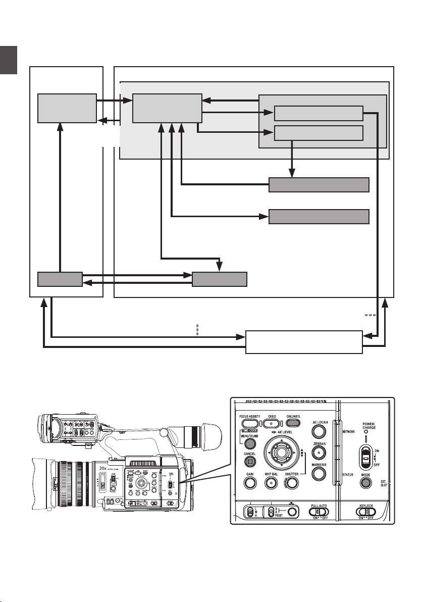
Operation Modes
Trimming Playback
Normal Playback
Camera Input
(Actions)
Execute [Delete Clips]
File Deletion in Progress
Exit Trimming Operation
(Successful/Failed/Stopped)
Execute
[Trim This Clip]
Thumbnail
Display
Playback
Camera Mode
Media Mode
* Selecting a mode other than the Metadata Edit mode via the web
browser, or selecting [Exit] on the [Remote Edit Mode] screen
Upon access via a web browser and selecting [Change] on the
[Change to Remote Edit Mode?] screen on the camera or the web browser
*
Exit FTP
Operation
(Successful)
Remote Edit Mode
FTP in Progress
FTP in Progress
Trimming in Progress
Exit/Cancel File Delete Operation (Successful/Failed/Stopped)
Exit/Cancel FTP Operation (Successful/Failed/Stopped)
Execute [FTP Upload]
[CANCEL]/[MENU/THUMB] Button
Press and hold [MODE]
Set Button (R)
[ONLINE/3] Button
Press and hold [MODE]
[MODE] Button
[MODE]
Button
This camera recorder has three operation modes - Camera mode, Media mode, and Remote Edit mode.
.
Introduction
Operation Modes
24
Page 25

Operation Mode Description
Camera Mode
This is
0
0
0
Memo :
0
the camera shooting mode. The camera recorder starts up in Camera mode
when the power is turned on.
Camera images are output to the viewfinder and LCD monitor. When a recordable
media is inserted, the camera recorder enters the recording standby mode. “STBY”
appears on the operation mode display area of the LCD monitor and viewfinder.
Press the [REC] trigger button to start recording.
Playback of recording media is not possible in the Camera mode. However, you
can check the most recently recorded video clip.
(A P86 [Viewing Recorded Videos Immediately (Clip Review)] )
Introduction
Media Mode
Remote Edit
Mode
This mode
0
When a playable recording media is inserted, the thumbnail or playback screen is
0
displayed on the viewfinder and LCD monitor.
Press and hold the [MODE] selection button to enter the Media mode when you
0
are not shooting in the Camera mode. Once the camera recorder is in Media mode,
thumbnails of the selected media slot are displayed.
This mode enables the list display and editing of the recorded clip data through
0
access to the clip list display page via a web browser on a smartphone, tablet
terminal, or PC.
When you access via a web browser on a smartphone, tablet terminal, or PC, “It
0
is necessary to change the camera mode to "Remote Edit Mode". Change the
mode.” appears on the web browser. Also,
displayed on the display screen of the camera unit.
Selecting [Change] on the camera recorder and pressing the Set button switches
to the Remote Edit mode, and enables display of the clip list and editing of the clip
metadata.
(A P196 [ Clip Metadata ] )
(A P198 [Uploading a Recording Clip via a Web Browser] )
Memo :
If you access via a web browser on devices such as a smartphone, tablet terminal,
0
or PC while recording is in progress, the message appears after recording stops.
If playback is in progress, the message appears once the files are closed
0
automatically, such as when playback stops.
allows you to play back or delete clips recorded on the recording media.
“Change to Remote Edit Mode?” is
Operation Modes
25
Page 26
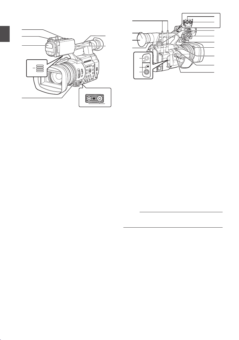
Names of Parts
o
Bottom
A
B
C
D
G
H
F
E
K
L
J
R
X
V
T
W
I
M
O
N
S
Q
P
U
Introduction
.
A
Shoe
For mounting separately sold lights and
accessories.
B
Tally Lamp
(A P47 [Tally Lamp and LED] )
(
A P253 [Blinking of the Tally Lamp] )
C
Built-in Microphone
(A P74 [Audio Recording] )
D
Monitor Speaker
(A P100 [Audio Output during Playback] )
E
Cross-Shaped Button (JKHI)/Set Button (R)
For operating the menu and cursor and for
0
confirming a setting, as well as for configuring
the settings for time code and user’s bit.
When a function is assigned to the cross-
0
shaped button, it functions as a user button.
(A P46 [Assignment of Functions to User
Buttons] )
F
Tripod Mounting Screw Hole
(A P33 [Attaching the Tripod (Sold
Separately)] )
G
[FIX/VAR/OFF] zoom speed switch
(A P59 [Zoom Operation] )
For switching the zoom speed of the zoom lever
X at the handle.
H
Accessory Mounting Screw Hole
Names of Parts
26
.
I
Wireless LAN Antenna Terminal A
(A P34 [Attaching the Wireless LAN
Antennas (Supplied) A] )
J
Viewfinder
(A P43 [Adjusting the LCD Monitor and
Viewfinder] )
K
Eyecup
Prevents external light from entering the
viewfinder screen and cameraman’s vision.
L
Visibility Adjustment Lever
(A P43 [Adjusting the LCD Monitor and
Viewfinder] )
M
[x] Headphone Jack (Φ3.5 mm)
(A P76 [Monitoring Audio Sound During
Recording Using a Headphone] )
N
[TC IN/OUT] switch
(A P81 [Synchronizing Time Code on
Another Camera] )
O
[TC] TC Input/Output Terminal
(A P76 [Time Code and User’s Bit] )
P
[REC] Record Trigger Button
Starts/stops recording.
Memo :
This switch is interlocked with the [REC/HOLD]
button W at the top of the handle.
Q
[EXP.FOCUS/9] Expanded Focus Assist/User
9 Button
For switching the expanded focus ON or
0
OFF.
(A P62 [Expanded Focus Function] )
You can also use it as a user button by
0
assigning a specific feature in the menu
setting to this button.
R
Zoom Lever at the Grip
(A
P59 [Using the Zoom Lever at the Grip] )
Page 27

S
Hood Release Button
(A P34 [Attaching/Detaching the Hood] )
T
External Microphone Cable Clamp
(
A P33 [Attaching the External Microphone
(Sold Separately)] )
U
[INPUT1/INPUT2] Audio Input Terminal 1, 2
(XLR 3-pin x 2)
(A P33 [Attaching the External Microphone
(Sold Separately)] )
V
Shoulder Belt Mount (x2)
For mounting a shoulder belt (sold separately).
Caution :
Be sure to use a shoulder belt with the strength
0
to withstand
If the shoulder belt is not properly attached, the
0
camera recorder may fall and cause injuries.
Check the [INSTRUCTIONS] provided with the
0
shoulder belt before using.
W
[REC/HOLD] Record Trigger Button/Lock
Switch
Starts/stops recording.
Set the switch to [HOLD] to lock the [REC]
Trigger button.
Memo :
This switch is interlocked with the [REC] button
0
P on the grip.
[REC] button P on the grip is not locked.
0
X
Zoom Lever on Handle
(A P59 [Using the Zoom Lever at the
Handle] )
the weight of this camera recorder.
Introduction
Names of Parts
27
Page 28
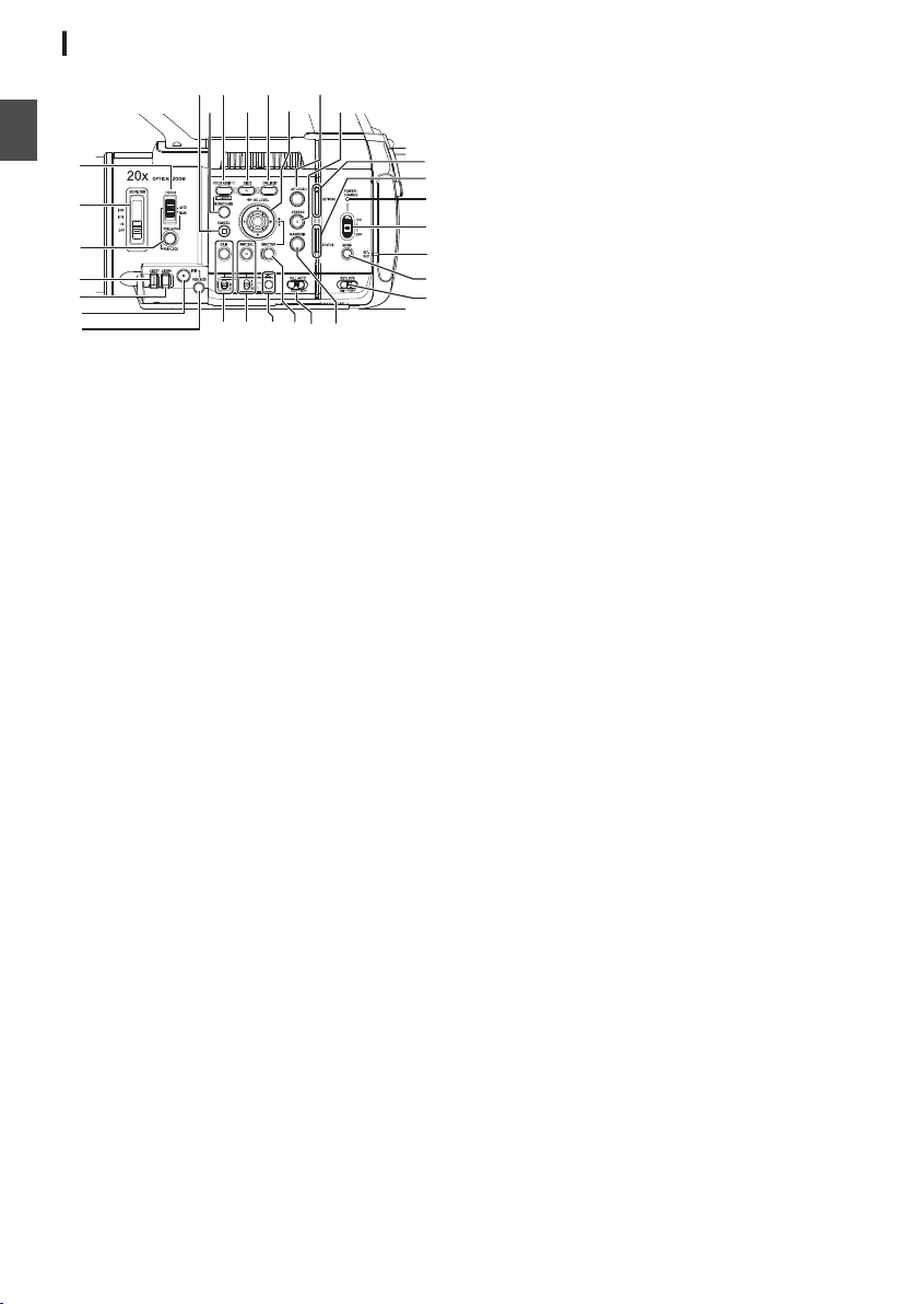
Side Control Panel
J
K
N
L
I
O
P
H
T
M
U
X
Z
V
b
Y
Q
R
S
W
a
A
B
C
D
E
F
G
Introduction
.
A
[FOCUS AUTO/MANU] Focus Switch
(
A P60 [Focus Operation] )
B
[ND FILTER] ND Filter Switch
Use the ND filter to keep the lens aperture in the
appropriate range.
OFF, 1/4, 1/16, 1/64
(A P68 [Setting the ND Filter] )
C
[PUSH AUTO/PUSH LOCK] Focus Push Auto/
Push Lock Button
(A P60 [One Push Auto Focus] )
(A P60 [Setting to Auto Focus Temporarily
(Push Auto Focus)] )
(A P60 [Locking the Focus] )
D
[USER7] Button
It can be assigned with a specific menu function.
(A P46 [Assignment of Functions to User
Buttons] )
E
[USER8] Button
It can be assigned with a specific menu function.
(A P46 [Assignment of Functions to User
Buttons] )
F
[IRIS] Iris Auto/Manual Selection Button
(A P65 [Adjusting the Iris] )
G
[PUSH AUTO] Iris Push Auto Button
(A P65 [Adjusting the Iris] )
H
[GAIN] Gain Auto/Manual Selection Button / [L/
M/H] Sensitivity Selection Switch
(A P66 [Setting the Gain] )
I
[WHT BAL]
White Balance Auto/Manual
Selection Button / [B/A/PRESET] Selection
Switch
(A P69 [Adjusting the White Balance] )
J
[y] One Push Auto White Balance Button
K
[SHUTTER] Shutter Speed Auto/Manual
Selection Button
(A P67 [Setting the Electronic Shutter] )
L
[FULL AUTO ON/OFF] Full Auto Switch
(A P64 [Adjusting the Brightness] )
(A P69 [Automatic White Balance Mode
(FAW: Fulltime Auto White balance)] )
M
[MARKER/6] Marker/User 6 Button
This button toggles ON/OFF the marker, safety
zone, and center mark displays.
You can also use it as a user button by assigning
a specific feature in the menu setting to this
button.
(A P46 [Assignment of Functions to User
Buttons] )
N
[KEYLOCK ON/OFF] Key Lock Switch
(A P54 [About the Operation Lock Feature
(KEYLOCK)] )
O
[MODE] Camera/Media Mode Selection Button
(A P24 [Operation Modes] )
P
EXT.SLOT Lamp
Lights up in green when a media is inserted into
EXT.SLOT, and lights up in red when the media
is being accessed.
Q
[POWER ON/OFF] Lock Power ON/OFF Switch
Turns ON/OFF the power.
down
0
Hold
the lock button (blue) in the center
to toggle ON/OFF.
When the power is turning OFF, “P.OFF”
0
appears on the LCD monitor and viewfinder.
Wait for 5 seconds or more to turn on the
0
power again.
(A P38 [Turning On/Off the Power] )
R
POWER/CHARGE LED
(A P35 [Using a Battery Pack] )
S
STATUS LED
(A P155 [ STATUS LED ] )
T
NETWORK LED
(A P155 [ NETWORK LED ] )
Names of Parts
28
Page 29

U
[ZEBRA/5]
(A P82 [Setting Zebra Pattern] )
You can also use it as a user button by assigning
a specific feature in the menu setting to this
button.
(A P46 [Assignment of Functions to User
Buttons] )
V
[AE LOCK/4] AE Lock/User 4 Button
When Gain, Iris, and Shutter are set to “AUTO”,
their respective values and the value of white
balance are locked when the [AE LOCK/4] button
is pressed.
You can also use it as a user button by assigning
a specific feature in the menu setting to this
button.
(A P46 [Assignment of Functions to User
Buttons] )
W
Cross-Shaped Button (JKHI)/Set Button (R)
The function changes according to the
operation status of the camera recorder.
o
(A P107 [Basic Operations in Menu Screen] )
Set Button (
Cross-shaped Button
(JK)
o
Shutter operation:
Set Button (R)
Cross-shaped Button
(
JK)
Cross-Shaped Button
(HI)
X
[ONLINE/3] Online/User 3 Button
Switches live streaming between ON/OFF.
0
(A P219
You can also use it as a user button by
0
assigning a specific feature in the menu
setting to this button. Initial setting: Live
streaming
A P46 [Assignment of Functions to User
(
Buttons] )
Y
[OIS/2] Optical Image Stabilizer/User 2 Button
For
ON or OFF.
You can also use it as a user button by assigning
a specific feature in the menu setting to this
button.
(A P46 [Assignment of Functions to User
Buttons] )
Zebra/User 5 Button
During menu operation (all modes)
R)
During Camera mode
[Starting Distribution] )
switching the image stabilizer feature mode
: Confirms menu items
and setting values
: Selects menu items
and setting values
Shutter ON/OFF
:
: Switches shutter
speed when shutter
is ON
: AE level operation
Z
[FOCUS ASSIST/1]
For switching the focus assist function ON or
OFF.
(A P61 [Focus Assist Function] )
You can also use it as a user button by assigning
a specific feature in the menu setting to this
button.
(A P46 [Assignment of Functions to User
Buttons] )
a
[MENU/THUMB] Menu/Thumbnail Button
Displays the menu screen during Camera
0
mode.
Switches between [Main Menu] and
0
[Favorites Menu] when the [MENU/THUMB]
button is pressed and held down while the
menu screen is displayed.
(
A P107 [Basic Operations in Menu Screen] )
Displays the
0
pressed during thumbnail display in the
Media mode.
Stops playback and displays the thumbnail
0
screen when the button is pressed during
playback screen display in the Media mode.
b
[CANCEL] Cancel Button
Cancels various settings and stops playback.
Focus Assist/User 1 Button
menu screen when the button is
Introduction
Names of Parts
29
Page 30
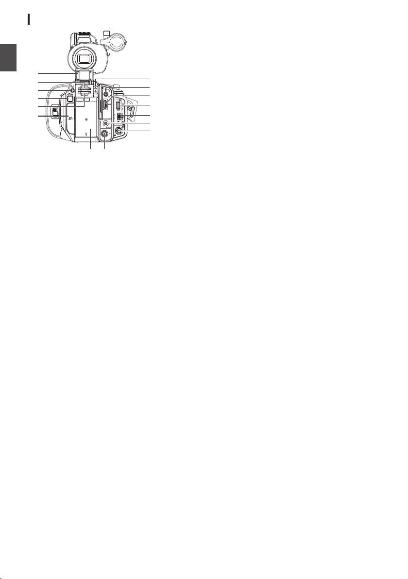
Rear Terminal
OPEN
BATTERY
BATTERIE:
7.2V
N
L
M
I
J
K
C
D
E
B
A
O
G
H
F
Introduction
.
A
SD Card Cover
B
Card Slot A
C
[SLOT SEL
For switching the active card slot during
shooting and playback.
D
[BATT.RELEASE] Button
(A P35 [Removing the Battery] )
]
Button
E
Card Slot B
F
[EXT.SLOT
]
SSD Media Adapter (sold separately) such as
KA-MC100 can be inserted into the slot.
(A P51 [Inserting the SSD Media Adapter] )
G
Battery
(A P35 [Using a Battery Pack] )
H
[DC] Terminal
Input terminal for DC 12 V power supply. For
connecting with the supplied AC adapter.
(A P36 [Using AC Power (DC IN Power)] )
I
[SDI OUT] Terminal
(A P182 [Connecting External Monitor] )
J
[REMOTE] Terminal
(A P183 [Connecting Wired Remote Control] )
K
[LAN] Terminal
For connecting the LAN cable.
L
[HOST] USB Host Terminal
For connecting a USB adapter according to the
intended purpose when you are connecting the
unit to a network.
(A P185 [Camera Setup for Network
Connection] )
M
[HDMI] Terminal
(A P182 [Connecting External Monitor] )
N
[AUX] Terminal (Φ3.5 mm)
For connecting to receiver such as wireless
microphone.
O
Access Lamp A/B
30
Names of Parts
Page 31
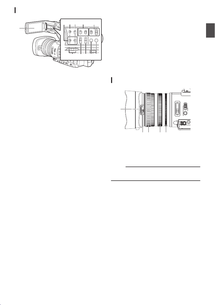
LCD Monitor
CH1
INT
INPUT1
INPUT2
AUTO
MANUAL
CH2
INPUT2
MONITOR
DISPLAY STATUS
INPUT1
PEAKINGLCD BRIGHT
CH2CH1
LINE
MIC
MIC
+48V
CH1
BOTH
CH2
EFCD
B
GHIK J
A
FOCUS
USER7 USER8
I
OPTICAL ZOOM20x
ND FILTER
1/64
1/16
1/4
OFF
AUTO
MANU
PUSH AUTO
PUSH LOCK
A
D ECB
.
A
LCD Monitor
(A P43 [Adjusting the LCD Monitor and
Viewfinder] )
B
[CH1/CH2] CH1/CH2 Recording Level
Adjustment Knob
A P74 [Audio Recording] )
(
C
[LCD BRIGHT +/-] LCD Display Brightness
Adjustment Button
(A P44 [Adjusting the Brightness] )
D
[PEAKING +/-] LCD/VF Contour Adjustment
Button
(A P44 [Adjusting the Contour (LCD)] )
(A P45 [Adjusting the Contour (Viewfinder)] )
E
[DISPLAY] Display Button
Press the [DISPLAY] button to switch to the
0
display screen during normal screen display
(when the menu screen is not displayed).
(A P41 [Display Screen] )
Switches between [Main Menu]
0
[Favorites Menu] when the [DISPLAY] button
is pressed while the menu screen is
displayed.
(A P107 [Basic Operations in Menu Screen] )
F
[STATUS] Status Screen Display Button
Press the [STATUS] button to display the status
screen on the viewfinder and LCD monitor
during normal screen display (when the menu
screen is not displayed).
(A P42 [Status Screen] )
G
[MONITOR]/[+/-] Audio Monitor Selection
Switch/Volume Adjustment Button
Switches the audio monitor and adjusts the
monitor speaker/headphone.
(A P76 [Monitoring Audio Sound During
Recording Using a Headphone] )
and
H
[INPUT1/INPUT2
] Audio Input Signal Selection
Switch
(
A P74 [Audio Recording] )
I
[CH2] CH2 Audio Input Signal Selection Switch
Select the audio input terminal to record to CH2.
(A P74 [Audio Recording] )
J
[CH1] CH1 Audio Input Signal Selection Switch
(A P74 [Audio Recording] )
K
[CH1/CH2 AUTO/MANUAL] CH1/CH2 Audio
Recording Mode Switch
(A P75 [Adjusting Audio Recording Level] )
Lens Section
.
A
Filter Built-In Screw
Transparent
0
filters for various effects can be installed.
Installable filter types: Φ82 mm
0
Memo :
Remove the
0
(A P34 [Attaching/Detaching the Hood] )
B
Lens Cover Open/Close Switch
(A P33 [Opening/Closing the Lens Cover] )
C
Focus Ring
A P60 [Focus Operation] )
(
D
Zoom Ring
(A P59 [Zoom Operation] )
E
Iris Ring
(A P65 [Adjusting the Iris] )
To operate auto iris, press the [IRIS] button on
the side control panel.
(a mark appears on the screen)
or
UV filter for lens protection, or
lens hood when installing the filter.
Introduction
Names of Parts
31
Page 32
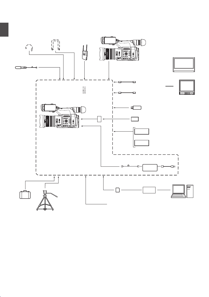
Basic System Diagram
[AUX]
[REMOTE]
[INPUT1]/
[INPUT2]
[HOST]
[EXT.SLOT]
[TC]
[HDMI]
[SDI OUT]
GY-HC550/GY-HC500
GY-HC550/GY-HC500
(AA-VC2)
(BN-VC296G)
(KA-MC100)
(KA-EN200)
[x]
[DC]
Carrying
Case
Tr i p o d
AC Adapter
Shoulder Belt Wireless
Microphone
Receiver
Headphone
SDI Cable BNC
Microphone
Monitor
Monitor
HDMI Cable
USB Network Adapter
Battery Charger
Remote Control Unit
Standard Package
SD Card SD Card Reader
A
Wireless LAN Antenna
SSD Media Adapter
H.265/HEVC
Streaming Adapter
Battery
Introduction
.
32
Basic System Diagram
Page 33
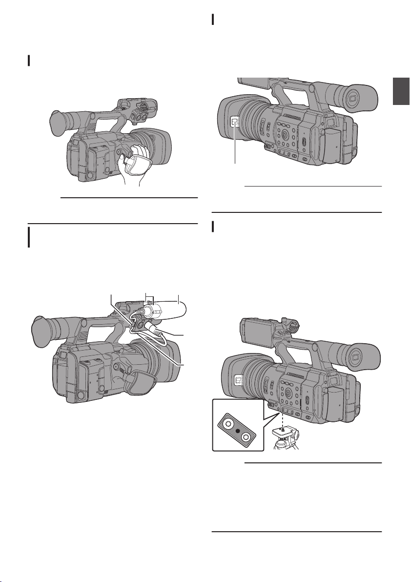
Settings and Adjustments
4
5
25
1, 3
Lens cover switch
o Bottom
Before Use
Adjusting the Grip Belt
Open the pad and adjust the position of the grip belt
accordingly.
.
Caution :
grip is loose, the camera recorder may fall
If the
0
off resulting in injuries or malfunction.
Attaching the External Microphone (Sold Separately)
You can attach a separately sold microphone to the
microphone holder.
Opening/Closing the Lens Cover
Use the lens cover open/close switch to open or
close the lens cover.
Before shooting, open the lens cover.
When this
lens cover to protect the lens.
.
Caution :
0
camera recorder is not in use, close the
Do not press against the lens cover with force.
Doing so may damage the lens or the cover.
Attaching the Tripod (Sold Separately)
Use the screw hole at the bottom of this camera
recorder.
(3/8×16UNC, 1/4×20UNC)
Use the screw hole that suits the tripod.
To prevent the camera recorder from falling off,
which may result in injuries or damages, read the
“INSTRUCTIONS” of the tripod to be used and
make sure that it is securely attached.
Preparations
.
1
Turn the knob on the microphone holder
counterclockwise to loosen and open the
microphone holder.
2
Place the microphone in the microphone
holder.
3
Turn the knob on the microphone holder
clockwise to secure the microphone.
4
Connect the microphone cable to the
[INPUT1]
5
Pin the microphone cable to the clamp.
6
Perform the settings for the microphone
correctly.
(A P
INPUT2] terminal.
or [
74 [Audio Recording] )
.
Caution :
If the camera recorder exceeds the weight limit
0
of the tripod, do not mount it on the tripod.
Use the tripod on a stable surface.
0
To prevent the camera recorder from falling,
0
attach securely using the rotation prevention
hole.
Use screws
0
with screw length 5 mm and below.
Settings and Adjustments Before Use
33
Page 34
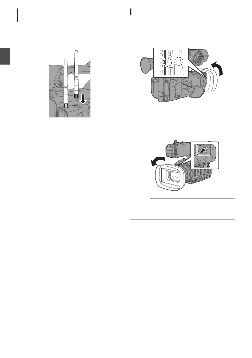
Attaching the Wireless LAN Antennas (Supplied) A
Attach the wireless LAN antenna by turning it in the
clockwise direction. Hold the base while attaching
the antenna.
Preparations
.
Caution :
Applying force to the wireless LAN antenna or
0
yanking it may damage the antenna so please
use caution when using the antenna.
is damaged, replacement is chargeable even
If it
during the warranty period.
(Part number: T9A-0095-00)
Use the antenna holders without removing
0
them.
Attaching/Detaching the Hood
Attaching the Hood
Align the markings on the camera recorder and
turn
hood;
it is locked.
Detaching the Hood
While pressing the hood release button, turn the
hood in the direction of the arrow (anti-clockwise)
to remove it.
the hood in the direction of the arrow until
.
Settings and Adjustments Before Use
34
.
Caution :
Remove the hood when attaching a filter,
0
teleconverter or
wide converter to the front of the
lens.
Page 35
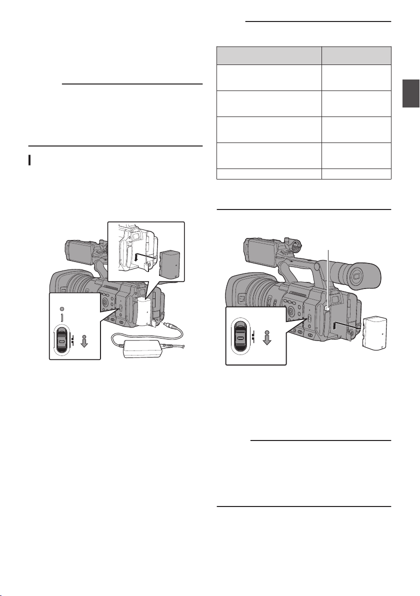
Power Supply
3
2
1
4
ON
OFF
POWER/
CHARGE
2
1
ON
OFF
To use this camera recorder, you can attach a
battery pack or connect an AC adapter to it.
(A P35 [Using a Battery Pack] )
(A P36 [Using AC Power (DC IN Power)] )
Caution :
POWER ON/OFF] switch to “OFF”
Set the [
0
before changing the power supply that operates
this camera recorder.
To charge the battery using a battery charger,
0
purchase a genuine charger that can charge the
recommended battery.
Using a Battery Pack
Charging the Battery
Charge the battery immediately after purchase or
when the battery power is running low.
* The battery is not charged when purchased.
Memo :
Blinking of
0
charging indicates the charge level.
[POWER/CHARGE] Lamp
during “POWER.OFF”
Alternates between a blinking
orange light (4 times) and
Alternates between a blinking
orange light (3 times) and
Alternates between a blinking
orange light (2 times) and
Alternates between a blinking
orange
You can charge the battery even when operating
0
the camera recorder using the AC adapter. The
lamp lights up in green during “POWER.ON”.
Removing the Battery
the [POWER/CHARGE] lamp during
Charge Level
Less than 25 %
light off (1 second)
Less than 50 %
light off (1 second)
Less than 75 %
light off (1 second)
light
(blinks once) and
light off (1 second)
Light goes out Fully charged
Less than 100 %
Preparations
.
1
Hold down the lock button (blue) at the
center of the [POWER ON/OFF] switch to set
to “OFF”.
2
Attach the supplied battery.
Slide it in until you hear a click.
3
Connect the supplied AC adapter to the
[DC] terminal.
Open
the cover of the [DC] terminal and connect
as shown in the diagram.
4
Connect the AC adapter to a power outlet.
The [POWER/CHARGE] lamp blinks during
0
charging and will go out after charging is
complete.
Remove the AC adapter after charging is
0
complete.
.
1
Hold down the lock button (blue) at the
center of the [POWER ON/OFF] switch to set
to “OFF”.
2
While pressing and holding the [BATT.
RELEASE]
battery in the direction of the arrow.
Caution :
Do not remove the battery when the [POWER
0
ON/OFF] switch is “ON”.
Leaving the camera recorder unused with the battery
0
attached will deplete the battery power even when
you set the [POWER ON/OFF] switch to “OFF”.
Remove the battery if you are not using the camera
recorder.
button, push up and remove the
Power Supply
35
Page 36
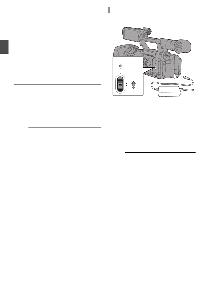
Estimated Charging and Continuous
ON
OFF
POWER/
CHARGE
2
1
Operating Times
o
Charging time
BN-VC296G (accessory):Approx. 5 hours
When the [POWER ON/OFF] switch is set to “OFF”
*
Memo :
If you
charge the battery immediately after using
0
while the battery is still warm, it may not be fully
charged.
It is recommended that you charge the battery
0
Preparations
in an environment between 10 °C and 30 °C
(50 °F and 86 °F). The battery may not be fully
charged or the charging time may be prolonged
if charged under low temperatures (below 10 °C/
50 °F). In addition, charging the battery under
high temperature (above 30 °C/86 °F) condition
may shorten the battery life.
o
Continuous operating time
BN-VC296G (accessory):Approx. 2 hrs 40 mins
*1 When [System] is set to
settings are in factory default
*2 When [System] is set to “HD” and all other
settings are in factory default
Memo :
Actual operating
0
the age of the battery, charging condition, and
operating environment.
Operating time is shortened in cold
0
environment.
The operating time may shorten when power
0
zoom is used, accessories are connected, or
when the LCD monitor is frequently used.
For purchase of spare batteries and battery
0
charger, please contact the local dealers in your
area.
Precautions for Batteries
Store the battery in a cool and dry place when
0
not in use. Do not expose the battery to high
temperatures (such as in a car under direct
sunlight). Failure to do so not only shortens the
battery life but also damages the battery.
If the operating time shortens drastically even
0
after charging, the battery may be reaching the
end of its life. Replace the battery with a new
one.
(*1)
Approx. 2 hrs 50 mins
(*2)
“4K” and all other
times may differ depending on
Using AC Power (DC IN Power)
Use the supplied AC adapter to operate the camera
recorder with AC power.
.
1
Connect the DC cable of the AC adapter to
the [DC] terminal of the camera recorder.
Check that the power switch of the camera
0
recorder is set to “OFF”.
Open the cover of the [DC] terminal and
0
connect as shown in the diagram.
2
Hold down the lock button (blue) at the
center of the [POWER ON/OFF] switch to set
to “ON”.
Power will be supplied to the camera recorder.
Caution :
Do not insert or remove the DC cable during
0
recording.
Do not use power supply of high voltage
0
fluctuation, containing noise such as ripple, or
with insufficient capacity.
Charging the Built-In Battery
The date/time and time code data are stored
0
using the built-in rechargeable battery.
When power is connected to the camera
0
recorder, the built-in battery always gets
charged. When the power is disconnected, the
battery gradually discharges.
The battery will be totally discharged if left
0
unused for
code data will be reset. When this happens, set
the [POWER ON/OFF] switch to “ON” to display
the [Initial Setting] screen, then set the date/
time.
(A P39 [Initial Settings] )
3 months and the date/time and time
36
Power Supply
Page 37
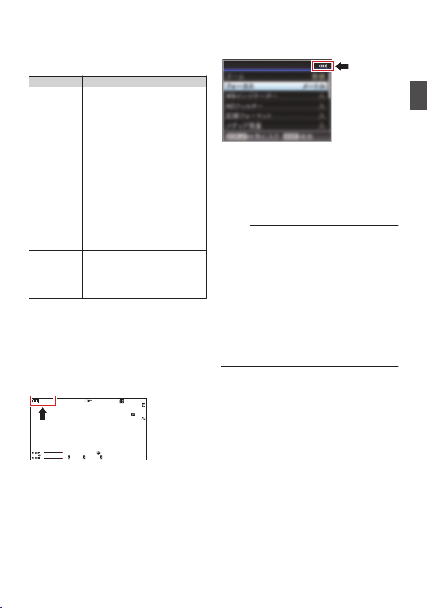
Power Status Display
282min
1
/60
F2. 8
AE
±0
ND1
/64
12 :34 : 56
ISO
102400
00:00 :00.00
5 . 6 f t
B 5600
K
4030 20 10 0
Display Settings
Viewfinder Screen and LCD Monitor
The power status is displayed on the display and
menu screens.
Display Description
B 7.4V
B 100min
C 30%
4 RES
F
T
G
P
Q
R
S
Memo :
If the
0
separately) is not used, the battery mark which
indicates the battery level may not appear.
Display Screen
(A P166 [Display Screen in Camera Mode] )
A P172 [Display Screen in Media Mode] )
(
Currently powered by a battery.
When the battery power runs out,
the battery mark appears hollow,
and “RES” (yellow) is displayed.
Memo :
You can set the display using
0
[LCD/VF] B [Display Type]
B
[Battery].
(A P130 [ Battery ] )
Acquisition of battery information
may fail if a genuine battery is not
used.
Appears when an error occurs
during battery charging.
Currently powered by an AC
adapter.
Camera recorder battery charging
in progress.
P130 [Details on charging
(A
condition] )
(A P130 [ Battery ] )
supplied battery (or equivalent battery sold
Menu Screen
(A P108 [Display and Description of the Menu
Screen] )
.
Warnings by Lamp and Warning Tone
Warning status is indicated by tally lamp and
warning tone.
The tally lamp blinks.
0
The warning tone is output from the monitor
0
speaker or [x] terminal.
Memo :
You can specify whether to turn on the warning
0
well as setting the volume in [A/V Set] B
tone as
[Audio Set] B [Alarm Level].
(A P137
0
[ Alarm Level ] )
event that the battery level runs low while
In the
it is being used, the camera recorder will stop
operating automatically.
Caution :
The remaining battery power and time are
0
displayed as they are from the battery
information. Accurate
data may not be displayed
depending on the battery condition. Replace the
battery as soon as possible when the remaining
battery power and time are low.
Preparations
.
Power Status Display
37
Page 38
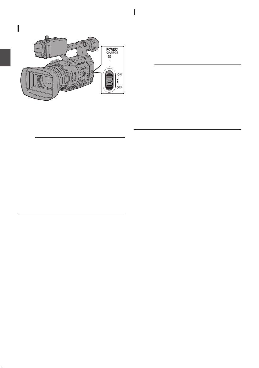
Turning On/Off the Power
Turning On the Power
Preparations
.
1
Hold down the lock button (blue) at the
center of the [POWER ON/OFF] switch to set
to “ON”.
The camera recorder starts up in Camera mode
and is ready for shooting.
Memo :
The camera recorder always start up in Camera
0
mode when the [POWER ON/OFF] switch is set to
“ON”. Use the [MODE] button at the side of the
camera recorder to switch mode.
(A P24 [Operation Modes] )
The camera recorder behaves as follows when an
0
AC adapter is connected.
0
If the battery is not fully charged, the battery will
be charged at the same time.
0
Even when a fully charged battery is used,
charge the battery briefly to confirm the
remaining battery power.
(A P35 [Power Supply] )
(A P37 [Power Status Display] )
Turning Off the Power
Sets the camera recorder to the recording standby or
stop mode.
1
Hold down the lock button (blue) at the
center of the [POWER ON/OFF] switch to set
to “OFF”.
2
Remove the battery and the power to the [DC]
terminal (when not in use for a long time).
Caution :
Do not set the [POWER ON/OFF] switch to “OFF”
0
during recording. Check that the operation mode
display is “STBY” or “STOP” before you turn off the
power.
If you have mistakenly set the [POWER ON/OFF]
0
switch to “OFF” during recording, wait for 5
seconds or more before you turn on the power
again.
When turning off the power, first set the [POWER
0
ON/OFF] switch of the camera recorder to “OFF”.
Do not remove the battery or turn off the AC power
while the [POWER ON/OFF] switch is set to “ON”.
Turning On/Off the Power
38
Page 39
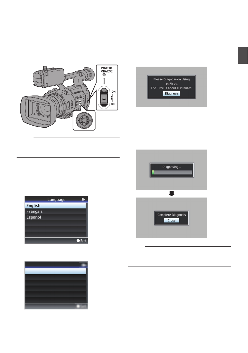
Initial Settings
Pусский
Español
Italiano
Deutsch
Français
English
Language
When the
screen for performing the initial settings in the
camera recorder appears.
Set the date/time of the built-in clock in the [Date/
Time] screen.
All operations are disabled until initial settings are
complete.
.
Memo :
0
0
1
power is first turned on, the Initial Setting
It is
recommended to use the AC adapter as the
power supply.
Be sure to close the lens cover.
Hold down the lock button (blue) at the
center of the [POWER ON/OFF] switch to set
to “ON”.
A language selection screen appears.
For U models
0
Memo :
The menus and messages on the screen of the
0
LCD monitor or viewfinder are displayed in the
selected language.
2
Select a language using the cross-shaped
button (JK), and press the Set button (R).
A self-diagnosis screen appears.
.
3
Ensure that the lens cover is closed, and
press the Set button (R).
Self-diagnosis starts.
0
A progress bar appears, and “Complete
0
Diagnosis
” appears when the diagnosis is
complete.
Preparations
.
.
For E models
0
.
Memo :
It takes about 6 minutes to complete the
0
diagnosis. During the diagnosis, do not operate
or turn off the camera recorder.
Initial Settings
39
Page 40
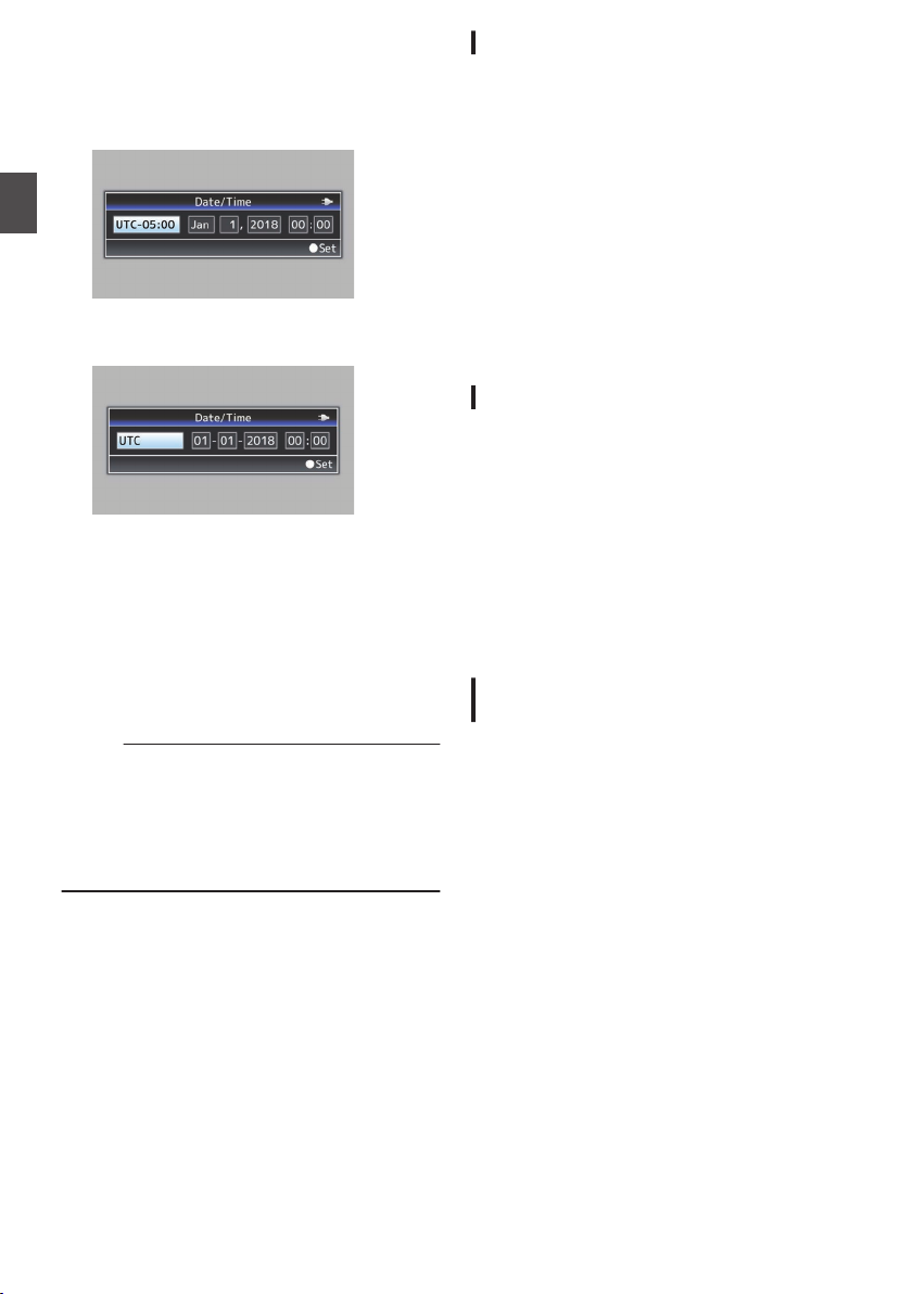
4
Press the Set button (R) after confirming
the exit screen.
The [Date/Time] screen appears.
For U models
0
Preparations
.
For E models
0
.
5
Set the time zone and date/time.
Move the cursor with the cross-shaped button
A
(HI) and select the setting item.
Change the values with the cross-shaped
B
button (JK).
6
Press the Set button (R) after setting is
complete.
The clock is set to 0 seconds of the input date/
time.
Memo :
The configured
0
on the LCD monitor and viewfinder screen and
be recorded to a recording media.
The value of the year can be set in the range of
0
“2000” to “2099”.
The configured date/time data is saved in the
0
built-in battery even if the power is turned off.
date/time data can be displayed
Changing the Time after Initial Setting
Setting the Date/Time
(A P155 [ Date/Time ] )
1
Select [System]
B [Date/Time]
.
The [Date/Time] screen appears.
2
Set the date and time.
Move the cursor with the cross-shaped button
A
(HI) and select the setting item.
Change the values with the cross-shaped
B
button (JK).
3
Press the Set button (R) after setting is
complete.
The clock is set to 0 seconds of the input date/
time.
Changing the Display Style
You can change the display style of the date/time
on the menu.
Setting the Date Display (Date Style)
(A P155 [ Date Style ] )
The date display can be changed in
[System] B
[Date Style].
Setting the Time Display (Time Style)
(A P
156 [ Time Style ] )
The time display can be changed in
[System] B
[Time Style].
Date/Time Display in Each Operation
Mode
During Camera mode:
Time of the built-in clock is displayed.
During Media mode:
Shooting
displayed.
date/time
of the clip being played back is
40
Initial Settings
Page 41
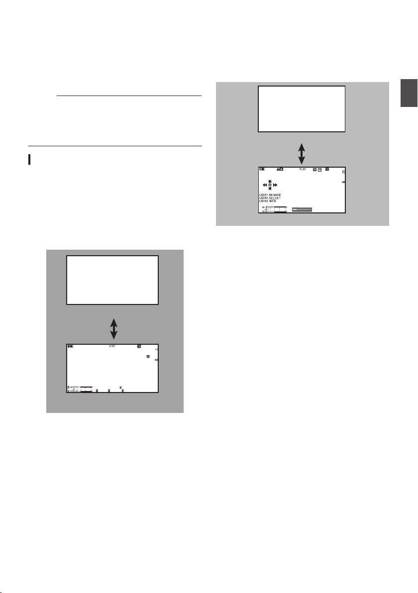
Displays on the LCD
282min
1
/60
F2.8
AE
±0
ND1
/64
12: 34 :56
ISO
102400
00:00: 00.00
5 . 6 f t
B 5600
K
4030 20100
Display Off
Display On
Jan 24 ,2019
3840x2160
30p 140M
282min
12: 34 :56
00:00: 00.00
1000/2000
4030 20 10 0
Display Off
Display On
Monitor and Viewfinder
You can display the camera status, recording
media information, zebra pattern, and various
markers in
viewfinder screen during shooting.
Memo :
0
Display Screen
Display Screen (VF/LCD) in Camera Mode
0
0
the video image on the LCD monitor and
When [A/V Set]
B [Video Set] B [SDI OUT] B
[Character] is set to “On”, the display screen and
menu screen are also displayed in the video
image of the video signal output terminal.
(A P132 [ Character ] )
(A P166 [Display Screen in Camera Mode] )
The display switches with every press of the
[DISPLAY] button.
(Display off B Display on B Display off)
Press the [STATUS
] button to switch to the
status screen.
(A P174 [Status Screen] )
Display Screen (VF/LCD) in Media Mode
(A P172 [Display Screen in Media Mode] )
This
the screen display during clip playback in
is
0
Media Mode.
The display switches with every press of the
0
[DISPLAY] button.
(Display off B Display on B Display off)
.
Preparations
.
Displays on the LCD Monitor and Viewfinder
41
Page 42
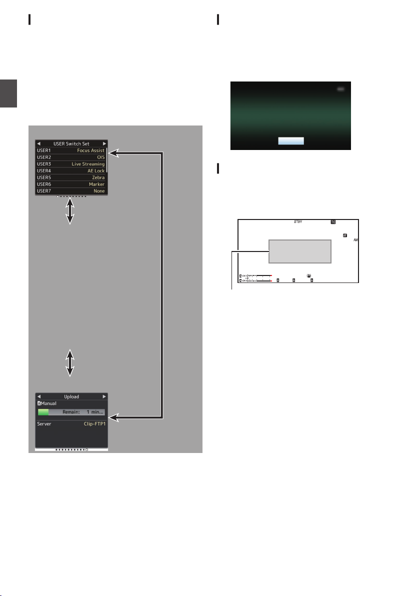
Status Screen
USER Switch Set
Upload
Camera
LCD/VF
Record Format
Audio
Video
Planning Metadata
Network
Connection Setup
Streaming
Exit
Remote Edit Mode
1
/60
F2. 8
AE
±0
ND1
/64
12 :34 : 56
ISO
102400
00:00 :00.00
5 . 6 f t
B 560 0
K
4030 20 10 0
Warning Display Area
This screen allows you to check the current
0
settings.
To display the status screen, press the
0
[STATUS]
Press the [STATUS] button again to return to the
0
normal screen.
Press the [MENU/THUMB] button at each status
0
screen (other than the [Camera] screen) to enter
the setting screen.
0
Use the cross-shaped button (HI) to switch
Preparations
between the screens.
button in the normal screen.
Remote Edit Mode Screen
This is a mode for accessing the page for editing
the metadata that is recorded in a clip via a web
browser on devices such as a smartphone, tablet
terminal, or PC.
(A P196 [ Clip Metadata ] )
.
Warning Display
Warning display is displayed in the display screen
(Camera mode, Media mode).
(A P248 [Error Messages and Actions] )
.
.
* These are screen examples. The contents
displayed are
and settings.
Displays on the LCD Monitor and Viewfinder
42
different depending on the model
Page 43
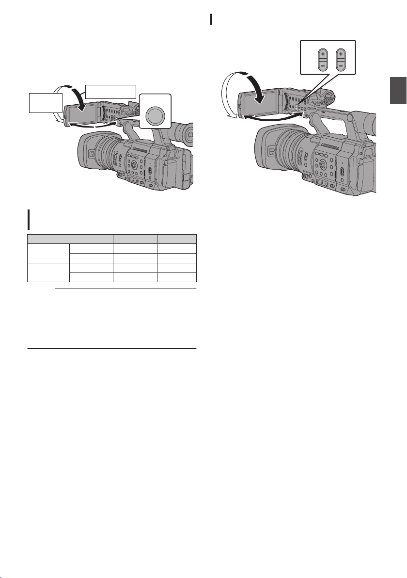
Adjusting the LCD Monitor
DISPLAY
Normal LCD
Inverted
LCD
2
1
PEAKINGLCD BRIGHT
3
Tilt 90 degrees downward
Tilt 180 degrees
upward
and Viewfinder
You can monitor video images on this camera
recorder using the viewfinder or LCD monitor.
Adjusting the LCD Monitor
Preparations
.
Displays on the LCD Monitor and
Viewfinder Screen (VF)
LCD Monitor Status LCD Display VF Display
LCD closed Normal LCD OFF ON
LCD opened Normal LCD ON OFF
Memo :
Press and hold the [DISPLAY] button for 2 seconds
0
to turn ON/OFF the LCD monitor.
The function to switch between LCD monitor and
0
viewfinder displays by pressing the [DISPLAY]
button can be canceled by opening/closing or
rotating the LCD monitor.
Inverted LCD ON OFF
Inverted LCD ON OFF
.
1
Open the LCD cover.
2
Incline the LCD monitor to a position that
enables easy viewing.
Rotate the LCD monitor to adjust the angle.
While the LCD monitor is open, you can
0
rotate it 180 degrees upward or 90 degrees
downward.
Rotating the LCD monitor 180 degrees
0
upward enables you to see the screen from
the
side. To display the image when it is
lens
viewed from the opposite direction (mirror
image), perform setting as follows.
Set [LCD/VF] B [LCD Mirror] to “Mirror” B Set
button (R)
(A
P127 [ LCD Mirror ] )
3
Adjust the brightness, contour, and
contrast of the LCD monitor.
can change the angle and brightness of the
You
LCD monitor
Changing the brightness of the screen will not
affect the recorded images.
according to your usage condition.
Adjusting the LCD Monitor and Viewfinder
43
Page 44
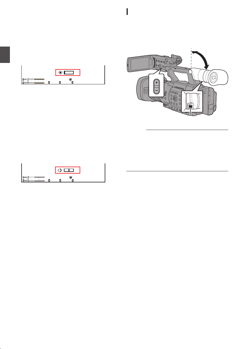
Adjusting the Brightness
1
/60
F2. 8
AE
±0
ND1
/64
ISO
102400
B 5600
K
1
/60
F2. 8
AE
±0
ND1
/64
ISO
102400
B 5600
K
PEAKING
1
2
Use the [LCD
brightness of the LCD monitor.
The [+] button brightens the monitor and the
0
[
-] button darkens it.
Press the [+] and [-] buttons simultaneously
0
to return to standard settings.
During adjustment, the brightness level is
0
displayed on the LCD monitor.
Preparations
.
Adjusting the Contour
Use the [PEAKING +/-] button to adjust the
contour of the LCD monitor.
(The contour of the viewfinder screen will also
be adjusted.)
The [+] button increases contour correction
0
and the [-]
correction.
Press the [+] and [-] buttons simultaneously
0
to return to standard settings.
During adjustment, the contour level is
0
displayed on the LCD monitor.
.
Adjusting the Contrast
Use the [LCD Contrast] menu to adjust the
contrast of the LCD monitor.
Adjust using [LCD/VF
0
(A P127 [ LCD Contrast ] )
Increasing the value increases the contrast.
0
[Setting Values:
BRIGHT
+/-] button to adjust the
button decreases contour
B [LCD Contrast].
]
+10 to -10] (Default value: 0)
Adjusting the Viewfinder
You can change the brightness and peaking of the
viewfinder screen according to your usage
conditions.
Changing the brightness of the screen will not
affect the recorded images.
.
Caution :
A high-definition viewfinder is used on this
0
camera recorder
focusing environment. Due to the characteristic
of the display device, colors may appear on the
images when you blink your eyes. This is not a
malfunction. It does not affect the recorded
images, SDI output, or HDMI output.
1
Incline the viewfinder vertically to a
position that enables easy viewing.
2
Turn the visibility adjustment lever to
adjust the visibility.
Turn the visibility adjustment lever to sharpen
the image on the viewfinder screen.
3
Adjust the brightness, contour, and
contrast of the viewfinder screen.
in order to provide an accurate
Adjusting the LCD Monitor and Viewfinder
44
Page 45

Adjusting the Brightness
Use the [VF Bright] menu to adjust the
brightness of the viewfinder screen.
Adjust using [LCD/VF]
0
(A P127 [ VF Bright ] )
Increasing the value increases the
0
brightness. [Setting Values: +10 to -10]
(Default value: 0)
B[VF Bright].
Adjusting the Contour
Use the [
contour of the viewfinder screen.
The contour of the LCD monitor will also be
adjusted.
(A P44 [Adjusting the Contour] )
Memo :
To display
0
monitor or press and hold the [DISPLAY] button.
Adjusting the Contrast
Use the [VF Contrast] menu to adjust the
contrast of the viewfinder screen.
(
Displaying in Black and White
You can display the viewfinder screen in black
and white.
(A P
PEAKING +/-] button to adjust the
the viewfinder screen, close the LCD
Adjust using [LCD/VF] B [VF Contrast].
0
A P127 [ VF Contrast ] )
Increasing the value increases the contrast.
0
[Setting Values:
[LCD/VF] B [VF Color] item B
0
button (R) B “Off” Select B Press Set button
(R).
127 [ VF Color ] )
+10 to -10] (Default value: 0)
Press Set
Preparations
Adjusting the LCD Monitor and Viewfinder
45
Page 46
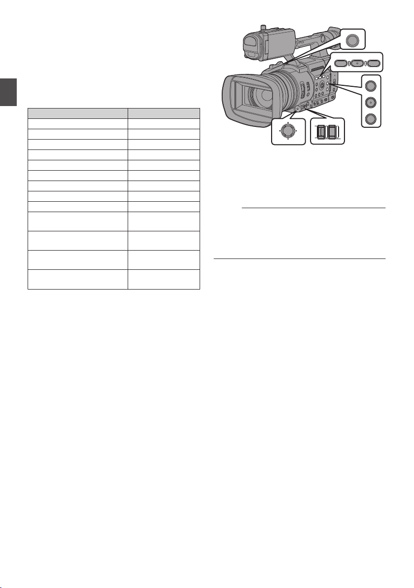
Assignment of Functions
USER7 USER8
ONLINE/3
OIS/2
FOCUS ASSIST/1
EXP.FOCUS/9
AE LOCK/4
ZEBRA/5
MARKER/6
to User Buttons
You can assign functions to the following buttons
and use them as user buttons.
By assigning
of the camera recorder can be enhanced.
Perform settings in the menu items corresponding
to each button.
Preparations
[FOCUS ASSIST/1] Button USER1
[OIS/2] Button USER2
[ONLINE/3] Button USER3
[AE LOCK/4] Button USER4
[ZEBRA/5] Button USER5
[MARKER/6] Button USER6
[USER7] Button USER7
[USER8] Button USER8
[EXP.FOCUS/9] Button USER9
Front Cross-Shaped Button
([J])
Front Cross-Shaped Button
([K])
Front Cross-Shaped Button
([H])
Front Cross-Shaped Button
([I])
functions to the buttons, the usability
Button Menu Item
USER10 ▲
USER11 ▼
USER12 ◀
USER13 ▶
.
1
Assign functions to the buttons from the
menu.
Configure each item to the user buttons in
[Camera Function] B [User Switch Set].
(A P
116 [User Switch Set Item] )
Memo :
Operations of the user buttons are interlocked
0
with the menu settings.
When the menu screen is displayed, these
0
buttons
function
as the menu operation buttons.
(A P107 [Basic Operations in Menu Screen] )
Assignment of Functions to User Buttons
46
Page 47
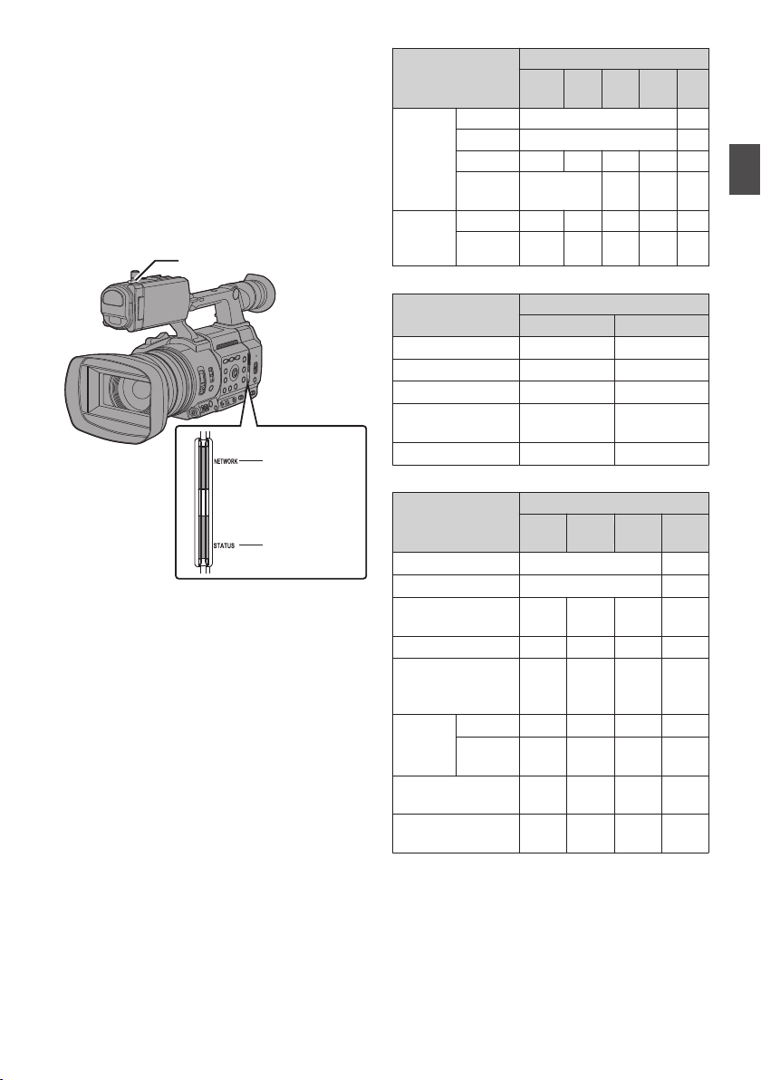
Tally Lamp and LED
NETWORK LED
STATUS LED
Tally lamp
This is the indicator lamp for recording, warning
and network.
The operation changes according to the menu
settings.
*
Set using [
LED]/[STATUS LED].
(A P154 [ Tally Lamp ] )
(A P155 [ NETWORK LED ] )
(A P155 [ STATUS LED ] )
.
System] B [Tally Lamp]/[NETWORK
Tally Lamp Behavior
0
Warning
Camera
Recorder
Status
Input from
Remote
Control Unit
0
Activating
Warning
During live streaming
Waiting for live streaming
connection
Error during live streaming
0
Activating
Warning
On Pre Rec standby
Recording
Remaining space in media
running low
(Only during recording)
Input from
Remote
Control Unit
Return over IP in Progress - -
Error during Return over IP - -
R
J
o
Alarm
Recording
During live
streaming
PROGRAM - - -
PREVIEW - - -
NETWORK LED Behavior
STATUS LED Behavior
PROGRAM -
PREVIEW -
:
Lights up
:
Flashes rapidly
:
Blinks slowly
[Tally Lamp] Setting
Rec/Live
Streaming
Streaming
R
R
[NETWORK LED] Setting
On Off
o
(Green)
J
(Red)
R
(Red)
R
(Orange)
R
(Orange)
[STATUS LED] Setting
REC/Pre
External
Rec
o
J
R
(Green)
R
(Red)
R
(Orange)
R
(Green)
Live
Rec
External
J
o
-
R
- - -
Return
over IP
(Green)
(Red)
- - -
- - -
- - -
R
- -
- -
R
(Green)
R
(Orange)
(Red)
- -
R
R
-
-
-
-
-
Off
-
-
Preparations
-
-
Off
-
-
-
-
Tally Lamp and LED
47
Page 48
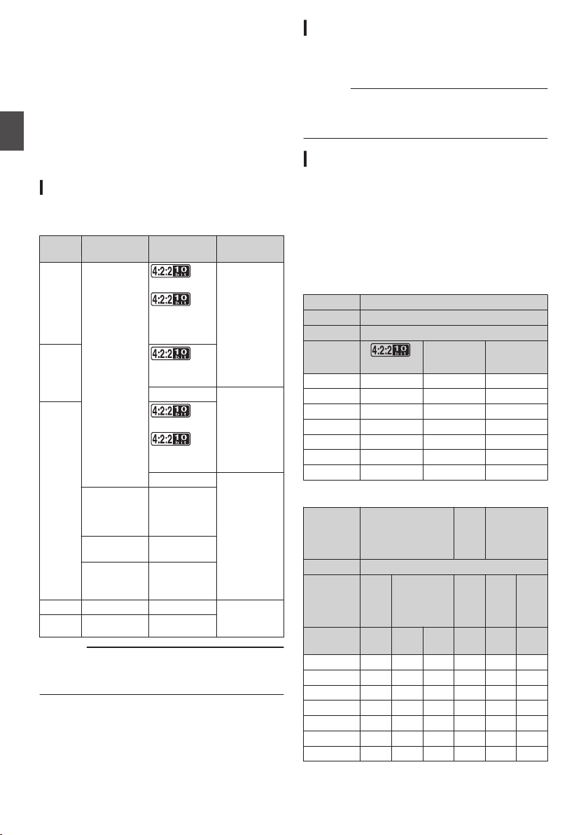
Recording Media
This camera
and videos except those in “4K EXT (SSD)” or “HD
EXT(SSD)” quality to the SD card (sold separately)
in the card slot.
Audio sound and videos in “4K EXT (SSD)” and
“HD EXT(SSD)” will be recorded to the SSD media
(sold separately) in the KA-MC100 SSD Media
Adapter (sold separately) that is inserted into the
Preparations
[EXT.SLOT].
Usable Cards
Format Setting and Usable SD Card
Combinations
System
HighSpeed
4K
HD
SD - - UHS-I U1 or
Web
Caution :
Using cards other than those from Panasonic,
0
TOSHIBA or SanDisk may result in recording
failure or data loss.
recorder saves recorded audio sound
Format Bit Rate
70M (XHQ),
QuickTime
(H.264)
QuickTime
(MPEG2),
MXF (MPEG2)
A
Exchange
(U model)
MP4
(H.264)
(E model)
- -
50M (XHQ),
50M (XHQ),
35M (UHQ)
150M,
150M
70M
70M (XHQ),
50M (XHQ),
50M (XHQ)
35M (UHQ)
35M (HQ),
25M (SP)
12M (LP),
8M (LP)
12M (LP),
8M (LP)
UHS-I U3 or
higher
UHS-I U1 or
higher, or Class
10 or higher
UHS-I U1 or
higher, or Class
6 or higher
higher, or Class
4 or higher
Usable SD
Card
Usable SSD Media
Refer to the “Instruction Manual
Adapter that is inserted into [EXT.SLOT] for steps
to mount the SSD media.
Caution :
Please refer to the product information page on
0
our website for a list of SSD media that have
been tested for compatibility.
” of the SSD Media
Estimated Recordable Time of SD Cards
The estimated recordable time is only a guide.
Differences may occur depending on the SD card
in use and the battery condition.
The recordable time varies according to the
0
settings in
[WBit Rate] and [YResolution].
(A
(A P158 [WBit Rate/ GBit Rate] )
(A P159 [ Y Resolution ] )
System 4K
Format QuickTime (H.264)
Resolution 3840x2160
Bit Rate
8 GB 6 6 13
16 GB 12 12 26
32 GB 25 25 53
64 GB* 50 50 106
128 GB* 100 100 212
256 GB* 199 200 424
512 GB* 399 401 848
* SDXC (Unit: minute)
System
Format QuickTime (H.264)
Resolution
Bit Rate
8 GB 13 18 25 96 274 588
16 GB 26 36 51 194 556 1190
32 GB 52 73 103 391 1119 2396
64 GB* 105 147 207 785 2243 4804
128 GB* 210 295 415 1572 4495 9626
256 GB* 420 590 832 3147 8998 19270
512 GB* 839 1180 1664 6297 18004 38557
* SDXC (Unit: minute)
[System], [WFormat], [WResolution],
P157 [WResolution/ G
150M
HD,
HD+Web (HD)
1920x
1920x1080,
1080
1280x720
XHQ
XHQ
(70M)
(50M)
Resolution] )
150M 70M
+Web
(Web)
720x
480,
720x
UHQ HQ HQ LP
SD,
HD
576
HD+Web
(Web)
960x
540
480x
270
Recording Media
48
Page 49
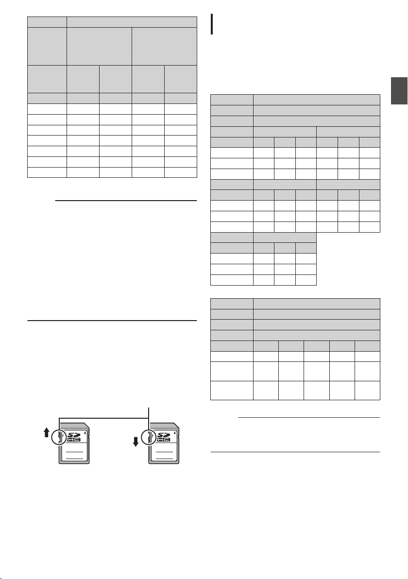
System HD
AB
Write/Delete Enabled Write/Delete Disabled
Write-Protect Switch
QuickTime
(MPEG2)
A
Format
(MPEG2)
Resolution
Bit Rate HQ SP LP (12M) LP (8M)
16 GB 51 70 139 197
32 GB 103 141 279 396
64 GB* 206 283 580 794
128 GB* 412 566 1121 1592
256 GB* 825 1133 2245 3186
512 GB* 1651 2267 4482 6376
* SDXC (Unit: minute)
Memo :
If the
0
other than this camera recorder or files that are
saved from a PC, the recordable time may be
shorter or data may not be properly recorded.
For each file format, up to 600 clips can be
0
recorded to one SD card on this camera
recorder. When 600 clips are recorded to one
card, the remaining space is displayed as 0 min
regardless of the estimated recordable time,
and no further recording can be performed.
When [System] is configured to “High-Speed”,
0
the remaining time display for recording to the
SD card will run out faster than usual.
Write-Protect Switch on the SD Card
Slide the write-protect switch upward to enable
A
writing or deleting.
Slide the write-protect switch downward to
B
prevent writing or deleting. (Images in the card
are protected.)
1920x1080,
1440x1080,
1280x720
8 GB 25 35 68 97
SD card contains files recorded by devices
,
MXF
A
1440x1080 1920x1080
Exchange,
MP4 (H.264)
1280x720
Estimated Recordable Time of SSD Media
The estimated recordable time is only a guide.
Differences may occur depending on the SSD
media in use and condition of the battery.
The recordable time varies according to the
0
settings in [System]
[GBit Rate].
System 4K EXT (SSD)
Format ProRes
Resolution 3840x2160
Frame Rate 60p 50p
Bit Rate
500 GB 34 50 72 40 60 86
1 TB 67 101 144 80 121 173
2 TB 134 201 289 161 241 346
Frame Rate 30p 25p
Bit Rate 422HQ 422 422LT 422HQ 422 422LT
500 GB 67 100 144 80 120 172
Frame Rate 24p
Bit Rate 422HQ 422 422LT
500 GB 84 125 180
1 TB 167 251 359
2 TB 335 502 719
System HD EXT (SSD)
Format ProRes
Resolution 1920x1080
Bit Rate
Frame Rate 60p 50p 30p 25p 24p
500 GB 130/200 160/240 270/400 320/480 330/500
1 TB 270/400 320/480 540/800 640/960
2 TB 540/800 640/960
Memo :
The maximum recording time is 4 hours in the
0
“4K EXT (SSD)” and “HD EXT(SSD)
Recording stops upon exceeding 4 hours.
422HQ
1TB 134 201 288 161 240 345
2TB 268 402 576 321 481 690
, [GFrame Rate], and
422 422LT
(Unit: minute)
422HQ
422HQ/422
1100/
1600
422 422LT
1300/
1920
(Unit: minute)
” modes.
Preparations
670/
1000
1340/
2000
.
Recording Media
49
Page 50
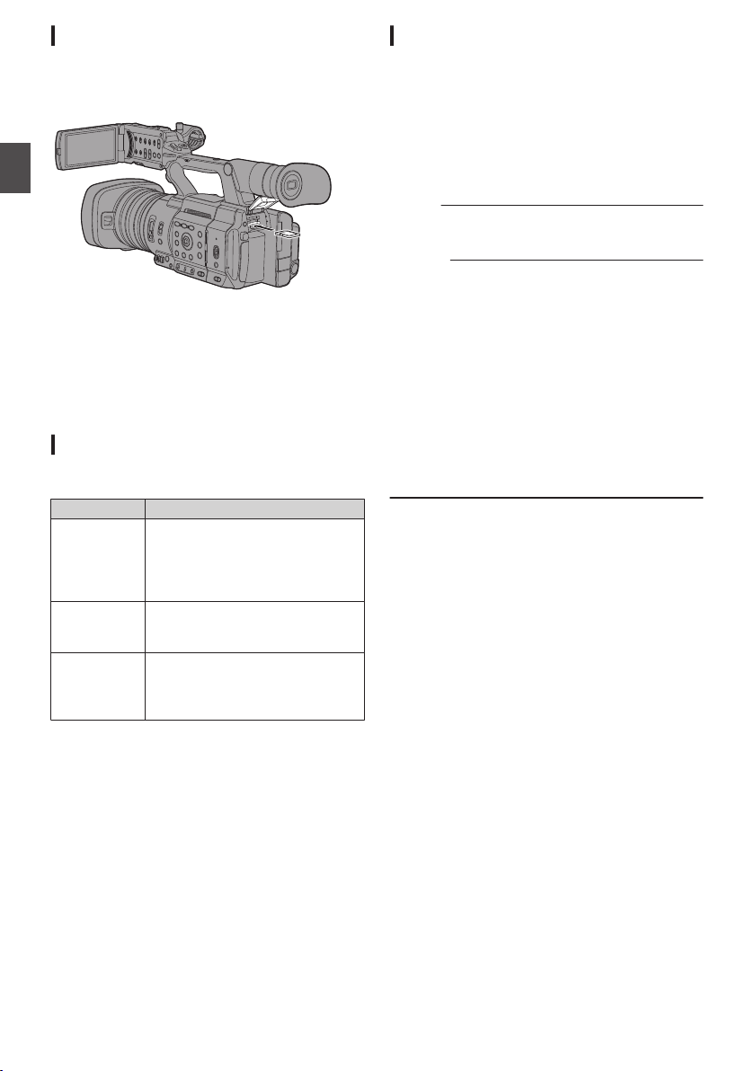
Inserting an SD Card
This camera recorder comes with two card slots
(Slot A and B) for video/audio recording and
playback.
Preparations
.
1
Open the SD card cover.
2
Insert an SD card into the slot with the
notched corner of the card on the right.
The status indicator of the card slot to which the
card was inserted lights up in red.
3
Close the SD card cover.
Card Slot Status Indicator
The following table shows the respective states of
slot A and B.
Lamp Slot Status
Lights up in
red
Lights up in
green
Light goes out0SD card is not inserted.
The inserted SD card is being
accessed. (writing/reading data)
Do not turn off the power of the
recorder
camera
card.
On standby. The inserted SD card
can be used for recording or
playback.
An unusable card is inserted.
0
An SD card is inserted but a
0
different slot is selected.
or remove the SD
Removing the SD Card
1
Check that the SD card to be removed is not
being accessed (status indicator of the
card slot lights up in red).
2
Open the SD card cover.
3
Push the SD card and remove it from the
slot.
4
Close the SD card cover.
Memo :
When both slots are inserted with usable SD
0
cards, the previously selected slot is used.
Caution :
Data may be lost if you turn off the power of the
0
camera recorder
is being accessed. All data recorded on the
card, including the file that is being accessed,
may be corrupted. Be sure to check whether the
status indicator is lit in green or turned off before
you turn off the power or remove the SD card.
If you mistakenly remove the card when it is
0
being accessed, reinsert the card only after the
status indicator goes off.
The SD card may not be recognized if you insert
0
and remove the card within a short time. When
this happens, remove the card and wait for a few
seconds before you reinsert.
or remove the SD card when it
Recording Media
50
Page 51
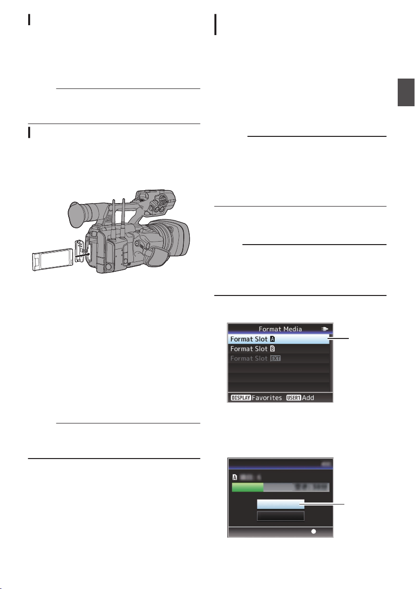
Switching the SD cards
2
4
Set
Cancel
Format
Format Media
When both card slots are inserted with SD cards,
you can use the [
card to use.
When the memory on an SD card is full during
recording, data recording automatically switches to
the other card.
Memo :
The [SLOT SEL
0
recording or playback. Cards will not be
switched even if you press the button.
SLOT SEL] button to switch the
] button is disabled during
Inserting the SSD Media Adapter
This unit is equipped with an [EXT.SLOT] for
recording and playing back video and audio in the
“4K EXT (SSD)” and “HD EXT(SSD)
.
1
Turn off the camera recorder.
2
Detaching the Battery
3
Open the EXT.SLOT cover.
4
With the USB terminal of the SSD Media
Adapter facing down, insert it into
[EXT.SLOT].
Insert it all the way until the tab locks into place.
5
Close the EXT.SLOT cover.
6
Attach the battery.
7
Turn on the camera recorder.
Memo :
If you are using the “KA-EN200” H.265/HEVC
Streaming Adapter (sold separately), attach it
using the same procedures above.
” modes.
Formatting (Initializing) of Recording Media
When any of the following recording media (SD
card or SSD media) is inserted, [
appears in the remaining level display area.
Format the card using the camera recorder menu.
Unformatted recording media
0
Recording media formatted under different
0
specifications
* For details of the menu operation, refer to
“[Basic Operations in Menu Screen]
(A P 107)”.
Caution :
Be sure to format the recording media on this
0
camera recorder. Recording media formatted
on a PC or other peripheral equipment cannot
be used on this camera recorder.
[!RESTORE] appears in the remaining level
0
display area when a recording media that
requires repair is inserted.
1
Select [System] B [Media] B [Format
Media].
(
A P154 [ Format Media ] )
Memo :
0
[Format Media G] can be selected in the
following cases.
0
[System] is set to “4K EXT(SSD)”
0
[System] is set to “HD EXT(SSD)”
0
[Slot Mode] is set to “Backup G”
2
Select the slot of the card to be formatted
and press the Set button (R).
.
3
The status of the selected recording media
is displayed.
4
Select [Format] and press the Set button
(R).
!FORMAT]
Preparations
.
Recording Media
51
Page 52
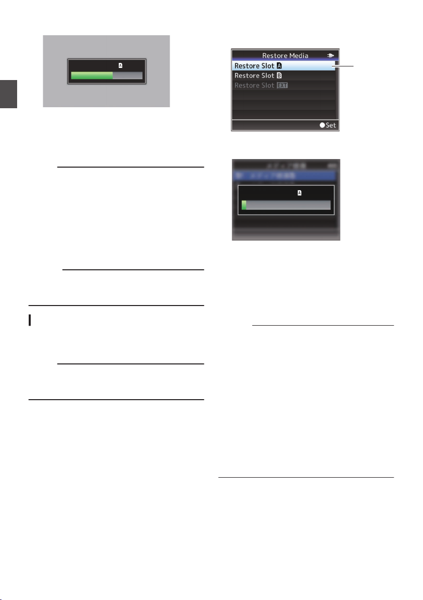
5
Formatting...
2
Restoring...
Formatting starts.
Preparations
.
6
Formatting is complete.
When formatting is complete, “Complete”
and the camera recorder returns to the [Format
Media] screen.
Memo :
The menu cannot be operated while formatting
0
is in progress, but recording is possible to the
slot where formatting is not executed.
Formatting cannot
0
be performed in the following
cases.
0
When recording to the recording media to be
formatted is in progress.
0
SD card is not inserted.
0
Write-protect switch of the SD card is set (z
is displayed).
Caution :
If you format a recording media, all data
0
recorded to it, including video data and setup
files, will be deleted.
Repairing the Recording Media
It is necessary to restore the recording media if an
abnormality occurs to the data in the recording
media due to some reasons.
Memo :
[!RESTORE] appears in the remaining level
0
display area when a recording media that
requires repair is inserted.
1
Select [System] B [Media] B [Restore
Media].
(
A P154 [ Restore Media ] )
appears
2
Select the recording media to be restored
and press the Set button (R
.
3
Restoring starts.
.
4
Restoring is complete.
When restoring is complete, “Complete”
0
).
appears and the camera recorder returns to the
[Restore Media] screen.
When no media that requires restoring is
0
inserted, the camera recorder returns to the
[Media] menu screen.
Caution :
[Restore Media]
0
can only be selected in Camera
mode. However, it cannot be selected while the
camera recorder is recording. Select [Restore
Media] in Camera mode when the camera
recorder is not recording.
[Restore Media] does not restore the SD card to
0
its original states completely. If restoring fails,
replace or format the recording media. Take
note that formatting erases all the information
inside the SD card.
Restoring cannot be performed in the following
0
cases.
0
Camera recorder is recording in progress.
0
SD card is not inserted.
0
Write-protect switch of the SD card is set (z
is displayed).
Recording Media
52
Page 53

Clips Recorded to Recording Media
ABCG0001
This is set to “xxxG” (“xxx” denotes the last 3
digits of the serial number) by default.
Clip Name Prefix (any four alphanumeric characters)
The Clip Number can be reset in
the menu.*
A number in automatic
ascending order is assigned in
the recording order.
Clip Number
Folders Created in the Recording Media
The captured image is recorded into different
folders according to the
Other than MXF (MPEG2): [DCIM]
0
0
MXF (MPEG2): [PRIVATE]
Memo :
By formatting (initializing) the recording media
0
from the [Format Media
recorder, folders required for recording in the
current [System] settings will be generated.
0
When the [System] settings and [WFormat]/
[YFormat] settings are changed, folders
required for recording in those settings will be
automatically generated.
Caution :
clip inside the folder is moved or deleted
When a
0
using the Explorer (Windows) or Finder (Mac),
recording to the recording media may fail if
formatting (initializing) of the media is not
performed.
[Format] settings.
A
] menu on the camera
Example: QuickTime
.
*
[Clip Set]
(A P161 [ Reset Clip Number ] )
Memo :
Before recording starts, you can set any
0
characters for the clip name prefix by using
[System] B [Record Set] B [Clip Set
Name Prefix].
(A P161 [ Clip Name Prefix ] )
Changes cannot be made after recording.
0
B [Reset Clip Number]
Preparations
] B [Clip
Clip (Recorded Data) and Clip Name
When recording is stopped, the images, audio
0
and accompanying data which are recorded
from start to stop are recorded as one “clip” on
the recording media.
An 8-character clip name is automatically
0
generated for the recorded clip.
(“Clip Name Prefix”
+ “Clip Number”)
Recorded Clips
The recorded
0
files but they can be played back continuously
on the camera recorder.
Clips may be recorded across the two SD cards
0
in card slots A and B depending on the recording
time of the clip.
Caution :
A clip
0
be played back continuously. Continuous
playback is only possible when the recording is
made on one card.
materials may be split into several
recorded across several SD cards cannot
Recording Media
53
Page 54
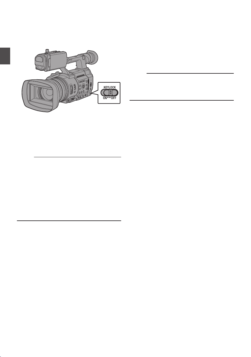
About the Operation Lock Feature (KEYLOCK)
You can use this feature to prevent erroneous
camera operation.
Preparations
.
1
Set the [KEYLOCK] switch to “ON”.
The
operation
0
lock icon (r) appears on the display
screen.
The operation
0
the [KEYLOCK] switch is set to “OFF”.
Memo :
The operation lock feature is only valid in the
0
Camera mode.
(A P24
[Operation Modes] )
The following remote operations are possible
0
even when the operation lock feature is turned
on (“On”).
0
Remote operation from the wired remote
control connected
0
Remote operation of the camera through
access via a browser on devices such as a
smartphone, tablet terminal, or PC.
lock turns on, and an operation
lock function is turned off when
to the [REMOTE] terminal.
Operation lock does not apply to the following
buttons and switches.
[
POWER ON/OFF]
0
[ND FILTER] switch
0
[TC IN/OUT] switch
0
Focus Ring
0
Zoom Ring
0
Iris Ring
0
Zoom Lever at the Grip
0
Zoom Lever on Handle
0
[FIX/VAR/OFF] switch
0
Memo :
Operation lock
0
if “Keylock Except Rec” is selected in [Camera
Function] B [KEYLOCK].
(A P113 [ KEYLOCK ] )
switch
does not apply to the REC button
About the Operation Lock Feature (KEYLOCK)
54
Page 55
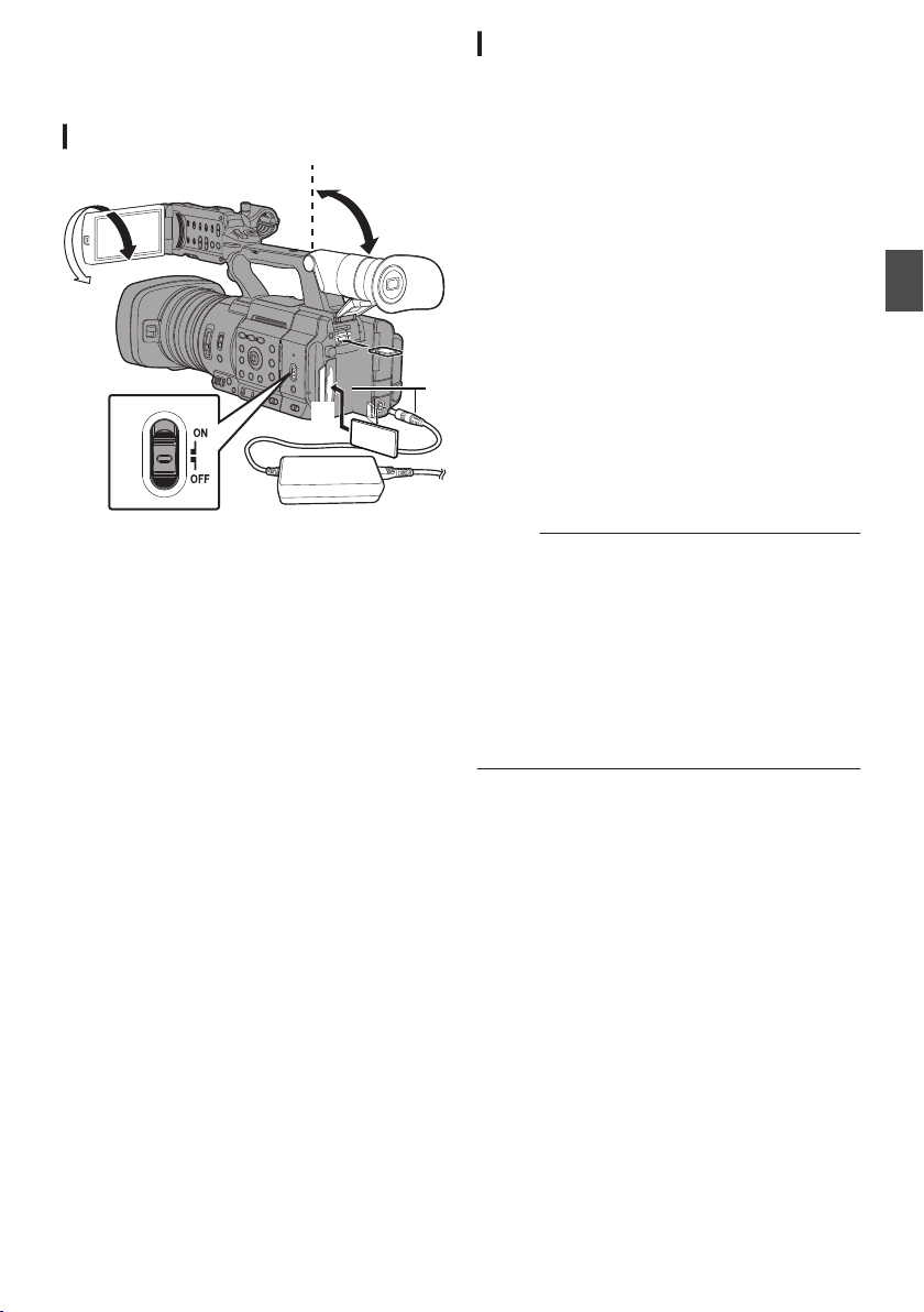
Basic Shooting
2
1
3
2
4
4
Procedures
Setting up
.
1
Supply battery or AC adapter power to the
camera recorder.
(A P35 [Power Supply] )
2
Insert the recording media.
(
A P
48 [Recording Media] )
3
Turn on the power of the camera recorder.
Setting the [POWER ON/OFF] switch to “ON”
starts up the camera recorder in the Camera
mode to enable shooting.
4
Adjust the angle of the LCD monitor and
viewfinder.
(A P43 [Adjusting the LCD Monitor and
Viewfinder] )
5
Set [System]
[Frame Rate] and [
[Record Set] B [Record Format].
You can select the definition of the recorded
0
videos, file format for recording/playback,
and the video recording format on this
camera recorder.
Press the [MENU/THUMB] button to display
0
the menu screen on the LCD monitor and
viewfinder.
, [Format], [Resolution],
Bit Rate] in [System] B
Shooting
1
Configure the video and audio input
settings.
You have to configure video settings such as
brightness adjustment (iris, gain, shutter) and
white balance adjustment in order to start
shooting. You also have to adjust the audio
input settings and audio recording level for
audio recording.
Adjusting the Brightness
0
(A P
64 [Adjusting the Brightness] )
Adjusting the White Balance
0
A P69 [Adjusting the White Balance] )
(
Adjusting Audio Input Settings and
0
Recording Level
(
A P74 [Audio Recording] )
2
Press
the [REC] button
the recording media.
The tally lamp lights up in red during recording.
Zoom Operation
0
(A P59 [Zoom Operation] )
Adjusting the Focus
0
(
A P60 [Focus Operation] )
Memo :
If both SD card slots A and B are loaded with
0
recordable SD
pressing the [REC] button starts recording only
to the media in the selected slot.
Configuring [System] B [Record Set] B [Slot
Mode] to “Dual” enables recording to be
performed simultaneously to the SD cards in
both slots A and B.
(A P88 [Dual Rec] )
The tally lamp can be turned off in [
0
[Tally Lamp].
3
Check the most recently captured images.
Press the user button that is assigned with
0
the Clip Review function. Doing so activates
the
captured images on the LCD monitor and
viewfinder screen.
After playback, the camera recorder returns
0
to standby mode (STBY).
(A P86 [Viewing Recorded Videos
Immediately (Clip Review)] )
cards in the factory default state,
and plays back the most recently
function
to start recording to
System] B
Shooting
Basic Shooting Procedures
55
Page 56

Selecting System
Definition, File
Format and
Video Format
You can select the definition of the recorded
videos, file format for recording/playback, and the
video recording format on this camera recorder.
Setting the Record Format Menu
1
Set [System], [Format], [Resolution],
[Frame Rate]
Shooting
[Record Set] B [Record Format].
2
Set each of the items.
[Selecting a System Definition] (A P
A
[Selecting a File Format] (
B
[Selecting a Video Format] (A P 57)
C
[Selecting the Aspect Ratio of SD Videos]
D
(A P 58)
3
After setting is complete for all items, press
the [
FOCUS ASSIST/1] button.
The recording format is switched.
0
A “Please Wait...
0
screen during switching.
Selecting a System Definition
The following definitions are available for selection.
4K EXT:
0
Records in 4K resolution (3840x2160)
4K:
0
Records in 4K resolution (3840x2160)
HD EXT:
0
Records clips in the HD (High Definition)
resolution (1920x1080)
HD:
0
Records in HD (High Definition) resolution
(1920x1080, 1440x1080 or 1280x720)
SD:
0
Records in SD (Standard Definition) resolution
(720x480 or 720x576)
Web:
0
Records in resolution (960x540, 720x480,
720x576, or 480x270) suitable for web
distribution
High-Speed:
0
Records in HD resolution (1920×1080)
and [Bit Rate] in [System] B
A P 56)
” message appears on the
56)
You can select a definition for the recorded images
from the following items under [System].
4K EXT (SSD):
0
Performs 4K EXT recording in EXT.SLOT.
4K:
0
Records in 4K quality for both slots A and B.
HD EXT(SSD):
0
Performs HD EXT recording in EXT.SLOT.
HD:
0
Records in HD quality for both slots A and B.
SD:
0
Records in SD quality for both slots A and B.
HD+Web:
0
Records
for slot B.
(A P87 [Recording Simultaneously at Two
Different Definitions] )
High-Speed:
0
Records in HD quality for both slots A and B.
HD quality for slot A, and Web quality
in
Selecting a File Format
Select a file format in [WFormat]/[YFormat].
The following file formats are available for
selection.
QuickTime (MPEG2):
0
QuickTime file format (.MOV)
MXF (MPEG2):
0
MXF file format
QuickTime (H.264):
0
QuickTime file format (.MOV)
Exchange: (U model only)
0
Sports Video Interop Group format (.MP4)
MP4 (H.264): (E model only)
0
MP4 file format
Memo :
Format is fixed at “ProRes” when [System] is
0
configured to
EXT(SSD)”.
Exchange (U model) and MP4 (E model) are
0
selectable only when [System
“HD”.
When Exchange (U model) or MP4 (E model) is
0
selected, backup recording and clip cutter
function cannot be used.
“4K EXT (SSD)” or “HD
] is configured to
Selecting System Definition, File Format and Video Format
56
Page 57
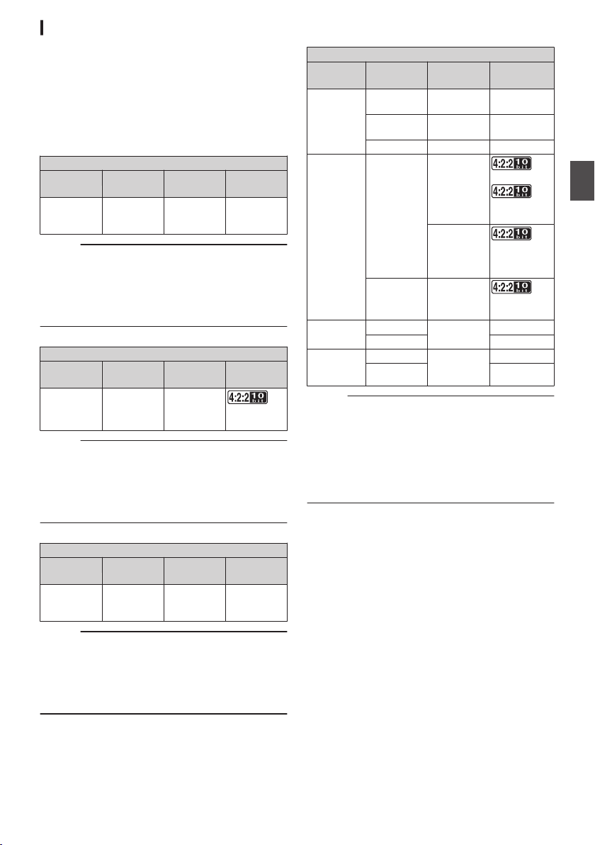
Selecting a Video Format
The selectable [Frame Rate]/[Bit Rate] changes
according to the settings of [System]/[Format]/
[Resolution].
List of Formats
The following is a list of file formats and video
formats that can be selected on this camera
recorder.
o
When [System] is set to “4K EXT (SSD)
Record Format
G
Format
ProRes 3840x2160 60p, 50p,
Memo :
[Rec Mode] is fixed at “Normal”.
0
[Slot Mode] is fixed at
0
The following functions cannot be used when 4K
0
EXT (SSD) is selected.
View Remote, Live Streaming, Return over IP,
Overlay Function, Clip Cutter Trig
o
When [System] is set to “4K”
FormatW ResolutionW Frame
W
QuickTime
(H.264)
Memo :
The following
0
is selected.
View Remote, Live Streaming, Return over
IP,Overlay Function
Each item for slot B is fixed at the same setting
0
as slot A.
o
When [System] is set to “HD EXT(SSD)
Format
G
ProRes 1920x1080 60p, 50p,
Memo :
[Rec Mode] is fixed at
0
[Slot Mode] is fixed at
0
The following functions cannot be used when
0
HD EXT(SSD) is selected.
View Remote, Live Streaming, Return over IP,
Overlay Function, Clip Cutter Trig
G
Resolution
3840x2160 30p,
functions cannot be used when 4K
G
Resolution
G
Frame
Rate
30p, 25p,
24p
“----”.
Record Format
Rate
25p,
24p
Record Format
Frame
G
Rate
30p, 25p,
24p
“Normal”.
“----”.
”
G
Bit Rate
422HQ,
422,
422LT
Bit Rate
W
150M,
150M, 70M
”
Bit Rate
G
422HQ,
422
o
QuickTime
(MPEG2),
MXF
(MPEG2)
A
QuickTime
(H.264)
Exchange
(U model)
MP4
(H.264)
(E model)
Memo :
0
0
0
System] is set to “HD” or “HD+Web”, the
When [
options for slot A are:
Record Format
W
Format
When
B is fixed at the same setting as slot A.
When [WFormat] is configured to “Exchange” or
“MP4(H.264)”, selection is possible only when
[System] is configured to “HD”.
The following functions cannot be used when
HD+Web is selected.
View Remote,
W
Resolution
1920x1080 60i, 50i,
1440x1080 60i, 50i 35M (HQ),
1280x720 60p, 50p 35M (HQ)
1920x1080 60p, 50p
1280x720 60p, 50p
1920x1080 60p 12M (LP)
1280x720 8M (LP)
1920x1080 50p 12M (LP)
1280x720 8M (LP)
[System]
Live Streaming or Return over IP
W
Frame
Rate
30p, 25p
60i, 50i,
30p, 25p,
24p
is set to “HD”, each item for slot
W
35M (HQ)
25M (SP)
70M (XHQ),
50M (XHQ),
50M (XHQ)
50M (XHQ),
50M (XHQ),
35M (UHQ)
50M (XHQ),
35M (UHQ)
Bit Rate
Shooting
Selecting System Definition, File Format and Video Format
57
Page 58
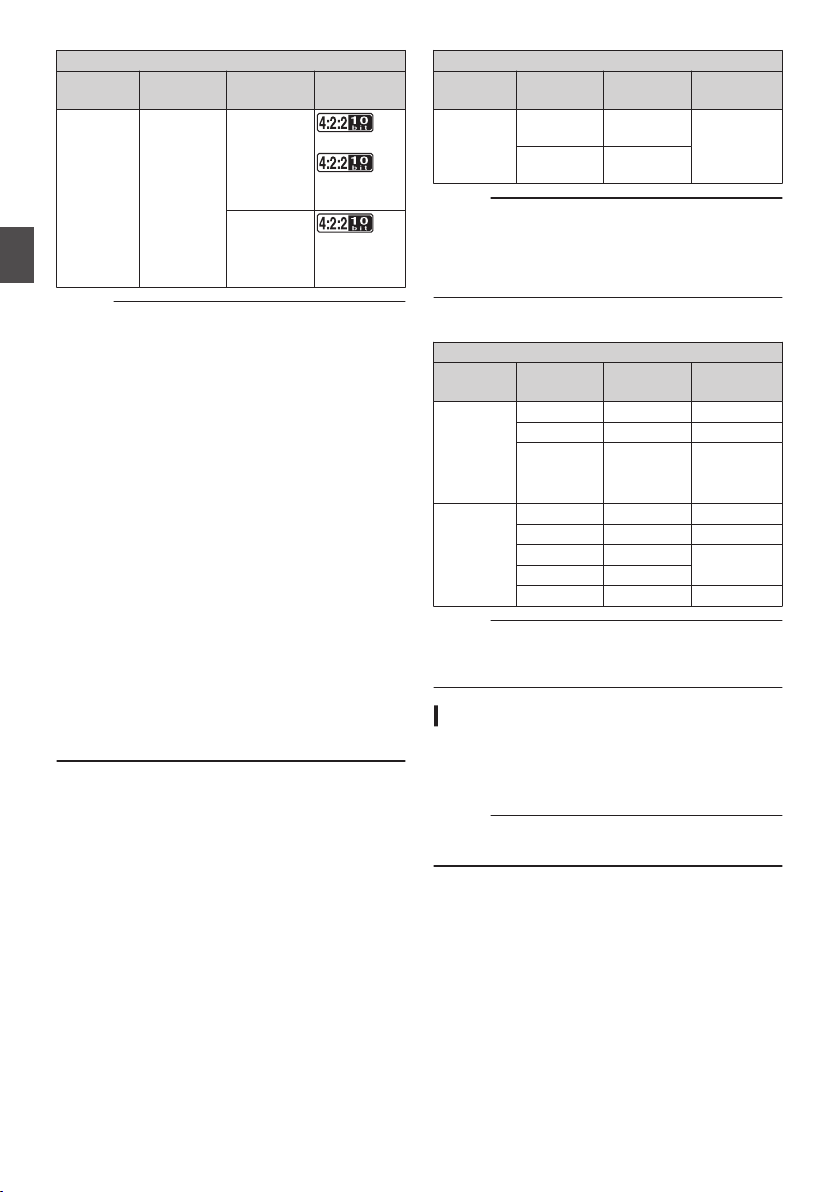
o
When [System] is set to “High-Speed”
Record Format
W
Format
QuickTime
(H.264)
Shooting
Memo :
[Rec Mode] is fixed at
0
[Slot Mode] is fixed at
0
The following functions cannot be used when
0
High-Speed is selected.
View Remote, Live Streaming, Return over IP,
Upload of recorded clip, time stamp recording,
Face Detection or Overlay Function
The settings for slot B are fixed at the same as
0
slot A.
Only “Rec Run” and “Regen” are the only TC
0
generator settings available.
It is not possible to set a shutter speed that is
0
slower than the frame rate.
The angle of view shifts to telephoto.
0
(35 mm conversion: [Normal] 28.0 mm to 560.0
mm B [High-Speed] 56.1 mm to 1122 mm)
The sensitivity of high speed shooting is lower
0
than normal shooting. In order to capture more
beautiful images, it is recommended to perform
shooting in a lighted environment.
The remaining space on the media (recordable
0
time to
usual.
(Example: For 120/60p, as the recording speed
is twice as fast as usual, the remaining space on
the media is reduced by approximately double
the speed.)
W
Resolution
1920x1080 120/60p,
the recording media) runs out faster than
W
Frame
Rate
100/50p
120/30p,
100/25p,
120/24p
“Normal”.
“Series”.
W
Bit Rate
70M (XHQ),
50M (XHQ),
50M (XHQ)
50M (XHQ),
50M (XHQ),
35M (UHQ)
o
When [System] is set to “SD”
Record Format
W
Format
QuickTime
(H.264)
Memo :
The following
0
is selected.
Overlay Function
Each item for slot B is fixed at the same setting
0
as slot A.
o
When [System
for slot B are:
Y
Format
QuickTime
(MPEG2),
MXF
(LP)
(MPEG2)
A
QuickTime
(H.264)
Memo :
The following functions cannot be used when
0
HD+Web is selected.
View Remote,
W
Resolution
720x480 60i
720x576 50i
function cannot be used when SD
] is set to “HD+Web”, the options
Y
Resolution
1280x720 60p, 50p 6M (LP)
960x540 30p, 25p 3M (HQ)
480x270 30p, 25p 1.2M (LP)
1280x720 60p, 50p 6M (LP)
960x540 30p, 25p, 24p 3M (HQ)
720x480 60i 8M (HQ)
720x576 50i
480x270 30p, 25p, 24p 1.2M (LP)
Live Streaming or Return over IP
W
Frame
Rate
(U model)
(E model)
Record Format
Y
Frame
Rate
W
Bit Rate
8M (HQ)
Y
Bit Rate
Selecting the Aspect Ratio of SD Videos
For setting the aspect ratio of the SD recording
image when [
You can select “16:9” or “4:3”.
(A P159 [ SD Aspect ] )
Memo :
For conditions
0
is fixed at “16:9”.
System] is set to “SD”.
other than those above, this item
Selecting System Definition, File Format and Video Format
58
Page 59

Zoom Operation
Adjusts the angle of view.
Optical zoom ratio: 1x to 20x
Dynamic zoom ratio: 1x to 40x
Set
Zoom].
Zooming can be operated using the following.
0
0
0
During the zoom operation, the zoom bar or
number will
screen.
Caution :
0
1
1
Memo :
0
2
Memo :
0
[Camera Function] B [Zoom] B [Dynamic
using
(A P113 [ Dynamic Zoom ] )
Zoom Lever at the Grip
Zoom Lever on Handle
Zoom Ring at the Lens Section
appear on the upper right corner of the
(A P169 [Zoom Display] )
Depending on the zoom speed, the zoom drive
noise of the power zoom may be recorded.
Using the Zoom Lever at the Grip
Press the zoom lever to zoom.
The zoom speed changes according to the
0
extent the zoom lever is being pushed.
Zooms into wide angle and increases the
0
angle of view when
Zooms into telephoto and decreases the
0
angle of view when “T” is pressed.
is pressed.
“W”
Using the Zoom Lever at the Handle
Set the [FIX/VAR/OFF] zoom speed switch
to “
Setting to “FIX” will allow the zoom operation to
move at
0
Set the zoom speed using [Camera
Function] B [Zoom] B [Handle Zoom Speed].
(A P113 [ Handle Zoom Speed ] )
Press the zoom lever at the handle to zoom.
When the [FIX/VAR/OFF] zoom speed switch is
set to “OFF”, the zoom lever at the handle
section cannot be used.
“VAR”.
FIX” or
the speed set in [Handle Zoom Speed].
Using Zoom Ring at the Lens Section
You can adjust the preferred angle of view by
turning the zoom ring.
Saving/Recalling Current Zoom
Position (Preset Zoom)
This allows you to register up to three zoom
positions.
1
Assign the “Preset Zoom1”, “Preset
Zoom2”, or
of the user buttons.
(A P46 [Assignment of Functions to User
Buttons] )
(
A P116 [USER1 to USER9, USER10 ▲,
USER11 ▼, USER12 ◀, USER13 ▶] )
2
Save the current zoom position.
Press any of the user buttons assigned with
0
the “Preset Zoom1
“Preset Zoom3” function for more than 1
second.
The current zoom position will be stored.
0
3
Recall the stored zoom position.
Press any of the user buttons assigned with
0
the “Preset Zoom1”, “Preset Zoom2
“Preset Zoom3” function and release within 1
second.
The camera recorder zooms to the stored
0
zoom position.
Memo :
Set the speed for shifting to the preset zoom
0
position and the rate of change for starting and
stopping the preset zoom operation in [Camera
Function] B [Zoom] B [Preset Zoom] B [Speed]/
[Ease In]/[Ease Out].
(A P114 [ Preset Zoom ] )
Operating other zoom maneuvers during a
0
zoom position recall will cancel the recall.
“Preset Zoom3” function to any
”, “Preset Zoom2
”, or
”, or
Shooting
Zoom Operation
59
Page 60
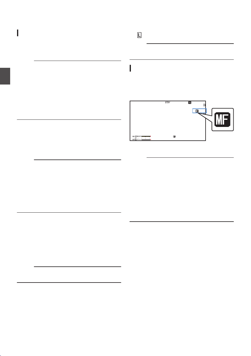
Focus Operation
12 :34 : 56
00:00 :00.00
5 . 6 f t
B 5600
K
Adjusting Focus Automatically
1
Set the [FOCUS AUTO/MANU] switch to
“AUTO”.
The auto focus icon e
Memo :
When [Camera Function]
0
Assist] is configured to “Direction”, it is possible
to move the auto focus point by turning the focus
ring.
Shooting
(A P115 [ AF Assist ] )
The AF area can be configured in [Camera
0
Function
] B [Focus] B [AF Area]. Selecting
“Multi” displays a “Multi” icon, while selecting
“Wide” shows a “Wide” icon.
(A P115 [ AF Area ] )
One Push Auto Focus
While in the Manual Focus mode, pressing the
[PUSH AUTO
] button (within 1 minute) makes the
camera recorder focus on the center of the frame
automatically.
Memo :
Face detection does not work during One Push
0
Auto Focus.
AF Assist does not function.
0
When the operation is complete, the camera
0
recorder returns to the Manual Focus mode
automatically.
One Push Auto Focus functions with emphasis
0
on the focusing speed. This function is not
suitable during recording.
Setting to Auto Focus Temporarily
(Push Auto Focus)
The camera recorder will shift to Auto Focus
0
mode temporarily and automatically adjusts
focus when
the [PUSH AUTO] button is pressed
during shooting in Manual Focus mode.
Release the [PUSH AUTO] button to return to
0
Manual Focus mode.
Memo :
Face detection
0
Focus.
appears on the screen.
B [Focus] B [AF
does not work during Push Auto
Locking the Focus
While in
the Auto Focus mode, pressing the [PUSH
LOCK] button locks the focus on the corresponding
point.
icon appears when the focus is locked.
An
Memo :
Performing any focusing operation when the
0
focus is locked disengages the focus lock.
Adjusting Focus Manually
1
Set the [FOCUS AUTO/MANU] switch to
“MANU”
The manual focus icon d appears on the
screen.
.
2
Turn the focus ring to adjust the focus.
Memo :
Using the Focus Assist or Expanded Focus
0
function makes it easier to focus.
(A P61
A P62 [Expanded Focus Function] )
(
Pressing
0
Focus mode activates the One-push Auto Focus
mode, while holding down the [PUSH AUTO]
button activates the Push Auto Focus mode.
(A P60 [One Push Auto Focus] )
(A P60 [Setting to Auto Focus Temporarily
(Push Auto Focus)] )
.
[Focus Assist Function] )
[PUSH AUTO] button in the Manual
the
Focus Operation
60
Page 61

AF Assist Function
Configure this function to move the auto focus point
closer to
temporarily by turning the focus ring.
or away from the camera or to activate MF
Set [Camera Function] B
0
0
Direction:
This option allows you to shift the auto focus
point to
near and far directions by turning the
focus ring during AF.
Focus is automatically adjusted to a focus
point near the position where the focus ring
stops turning.
0
Manual:
Temporarily activates MF when the focus ring
is turned during AF. The camera recorder
returns to the AF mode when the focus ring is
not operated for a some time.
[Focus] B [AF Assist].
MF Assist Function
This function activates AF operation for a short
interval when the focus ring is turned during MF.
Set [Camera Function] B
0
0
On:
Turning the
for a short interval after the operation, after
which the camera recorder returns to the MF
mode.
focus ring during MF activates AF
[Focus] B [MF Assist].
Focus Assist Function
When the
0
shooting, the focused area is displayed in color.
This enables easy and accurate focusing.
Select the color (blue, red or green) in the menu.
0
Memo :
When [LCD/VF]
0
Assist] B [Type] is set to “ACCU-Focus”, the
depth of field becomes shallower to enable
easier focusing.
(A P128
The “ACCU-Focus
0
automatically to “Off” after about 10 seconds.
Select the display color in [LCD/VF] B [Shooting
0
Assist] B [Focus Assist]B[Color].
(A
If you use the zebra function and the Focus
0
Assist function at the same time, it may be
difficult to see the effect of the Focus Assist. In
this case, turn off the zebra function.
Setting Focus Assist Function to a User Button
You can assign the “Focus Assist
button.
(A P46 [Assignment of Functions to User
Buttons] )
[F.ASSIST/1] button is pressed during
B [Shooting Assist] B [Focus
[ Focus Assist ] )
” function switches
P128 [ Color ] )
” function to a user
Focus Assist + Function
You can operate the Focus Assist and
0
Expanded Focus functions simultaneously by
pressing the user button assigned with “Focus
Assist +”.
Memo :
“Expanded Focus” is displayed during the
0
“Focus Assist +
setting in [Camera Function] B [User Switch
Set] B [Expanded Focus].
” operation regardless of the
Shooting
Focus Operation
61
Page 62
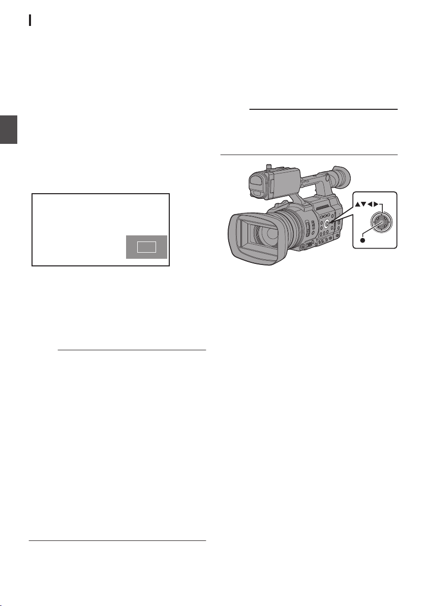
Expanded Focus Function
You can magnify the preferred area by pressing the
[EXP.FOCUS/9] button; doing so enables precise
focus to be established easily.
* You can also use the user button assigned with
the “Expanded Focus
[EXP.FOCUS/9] button.
(A P46 [Assignment of Functions to User
Buttons] )
(A P116 [USER1 to USER9, USER10 ▲,
USER11 ▼, USER12 ◀, USER13 ▶] )
1
Press the [EXP.FOCUS/9] button.
The
center
Shooting
0
the first time.
For subsequent operation of the button, the
0
area at which the operation was last
performed will be enlarged.
” function instead of the
area of the screen is enlarged for
Adjusting the Focusing by Face Detection
This function detects human faces and
automatically adjusts focus during Auto Focus.
It can also track moving objects.
When several faces are detected, you can select
one to focus on.
Memo :
This function can also adjust the brightness
0
automatically according
face detected.
(A P116 [Face Detection Function Settings] )
to the brightness of the
.
2
Use the cross-shaped button (JKH I) to
magnify the preferred area.
The portion that is being magnified is
0
displayed at the lower right corner of the
screen.
3
Press the [CANCEL] button to cancel the
setting.
Memo :
The display
0
equivalent.
To set the operation when the button is pressed,
0
go to [Camera Function] B [User Switch Set] B
[Expanded Focus].
(A P118 [ Expanded Focus ] )
0
Pressing and holding the Set button (
the position of magnification.
This function can be used together with the
0
Focus Assist function.
Magnifying an image does not alter the size of
0
the recorded image.
The cross-shaped button cannot be used as
0
user button while the area is being magnified.
This function is unavailable when
0
[Record Set] B [Record Format] B [System] is
set to “SD”.
When the display screen is turned off, the
0
magnified
will not be displayed.
of the enlarged screen is dot by dot
R) resets
[System]
at the bottom right of the screen
area
.
B
Focus Operation
62
Page 63
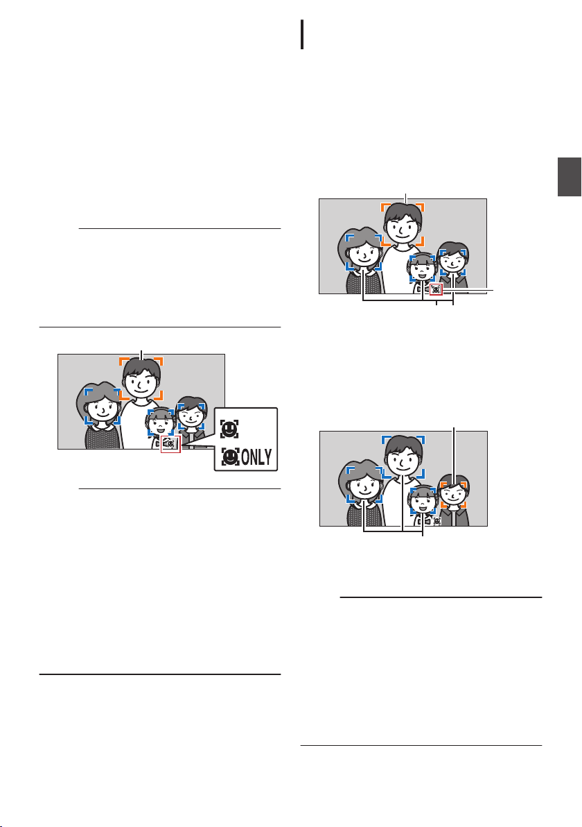
1
Detection Frame (Orange)
Detection Frame (Blue)
Detection Frame (Orange)
Blinking
Detection Frame (Blue)
Detection Frame (Orange)
Assign the “Face Detection
” function to any
of the user buttons.
(A P46 [Assignment of Functions to User
Buttons] )
2
Focus
the camera recorder on a person and
press the
user button that is assigned with
“Face Detection”.
When Face detection is enabled, the face
0
detection icon (q) appears.
An orange frame will appear on the face of
0
the person nearest to the center of the
screen.
frames will appear on the faces
Blue
of others.
Focus will be automatically adjusted for the
0
selected person.
Memo :
When the button assigned with “Face Only AF”
0
or the [
Camera Function] B [Face Detection] B
[Face Only AF] item is configured to “On”,
“ONLY” appears to the right of the face detection
icon, and auto focus functions only when a face
is detected. When a face cannot be detected,
the camera recorder switches manual focusing.
Selecting Specific Person from Several
Persons
1
Hold down the user button that is assigned
with “Face Detection
The camera
0
mode and the face detection icon (q) will
blink.
An orange frame will appear on the face of
0
the person nearest to the center of the
screen. Blue
of others.
.
2
Select a specific person.
0
Use the cross-shaped button (HIJK) to
select a person.
An orange frame will appear on the face of
0
the selected person and focus will be
automatically adjusted.
”.
recorder will enter face selection
frames will appear on the faces
Shooting
.
Memo :
If the detection frame does not appear, make
0
sure that Auto Focus mode is selected. Also, if
[Face Detection] is set to “AF&AE”, set at least
one of the iris, gain, and electronic shutter
control items to the automatic adjustment mode.
(A P64 [Adjusting the Brightness
Automatically: Automatic Brightness Adjustment
(AE) Mode] )
(A P65 [Auto Iris (Automatic Adjustment)
Mode] )
(A P66 [Automatic Gain Mode (Automatic
Gain Adjustment)] )
(A P67 [Automatic Shutter Mode (Automatic
Shutter Adjustment)] )
.
3
Press the Set button (R) to confirm the
person for face detection.
Memo :
Press the [CANCEL] button to cancel the
0
selection.
A face
0
can be selected by turning the focus ring
without entering the face selection mode.
The detection sensitivity and duration for
0
maintaining the current focus after losing sight
of the face can be configured in [Camera
Function] B [Face Detection] B [Sensitivity]/
[Holding Duration].
(A P116 [ Sensitivity ] )
(
A P116 [ Holding Duration ] )
Adjusting the Focusing by Face Detection
63
Page 64
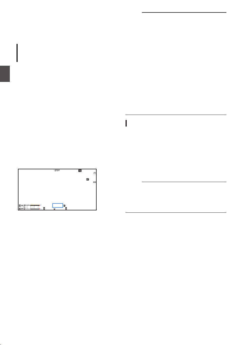
Adjusting the Brightness
1
/60
F2. 8
AE
±0
ND1
/64
12 :34 : 56
ISO
102400
00:00 :00.00
5 . 6 f t
B 5600
K
Adjust the brightness using Iris, Gain, Shutter
speed and ND filter according to the brightness of
the object.
Adjusting
Automatic Brightness Adjustment (AE)
Mode
Iris, Gain, Shutter speed and ND filter are
automatically adjusted
of the object to maintain optimum brightness.
To set only the Iris, Gain and Shutter to Auto mode,
Shooting
set the [FULL AUTO] switch to “OFF” before setting
each item to the automatic adjustment mode.
1
Set Gain, Iris and Shutter to Auto mode.
[Adjusting the Iris] (A P 65)
0
[Setting the Gain] (
0
[Setting the Electronic Shutter] (A
0
2
Set the target level (brighter/darker) to
maintain optimum brightness during
automatic adjustment.
This can be configured using the cross-
0
shaped
recorder unit.
This can
0
B [AE Level].
.
Brightness Automatically:
the
according to the brightness
A P 66)
(HI) on the side of the camera
button
be configured in [Camera Function]
P 67
Memo :
Setting the
0
[FULL AUTO] switch to “ON” to enter
the Full Auto mode also activates the automatic
brightness adjustment (AE) mode. In this case,
white balance is also switched forcibly to auto
mode.
The convergence speed of the automatic
0
adjustment for automatic brightness adjustment
(AE) can be set in the menu.
(A P111 [ AE Speed ] )
If one or more of the items (Gain, Iris and
0
Shutter) have been set to Auto mode, the value
of the
corresponding items when the user button
that is assigned “AE Lock” is pressed can be
fixed.
(A P117 [ AE Lock ] )
If one or more of the items (Gain, Iris and
0
Shutter) have been set to Auto mode, the
automatic brightness adjustment (AE) mode is
enabled.
)
Adjusting the Brightness Manually
When the [FULL AUTO] switch is set to “OFF”,
some or
be manually adjusted.
1
2
Memo :
all of the items (Iris, Gain and Shutter) can
Set the [FULL AUTO] switch to “OFF”.
Adjust the Iris, Gain and Shutter speed.
[Adjusting the Iris] (A P 65
0
[Setting the Gain] (
0
[Setting the Electronic Shutter] (A
0
The brightness cannot be manually adjusted in
0
A P 66)
the Full Auto mode.
If Iris, Gain and Shutter Speed are manually
0
adjusted, the [AE Level
] setting is temporarily
disabled.
)
P 67
)
64
Adjusting the Brightness
Page 65
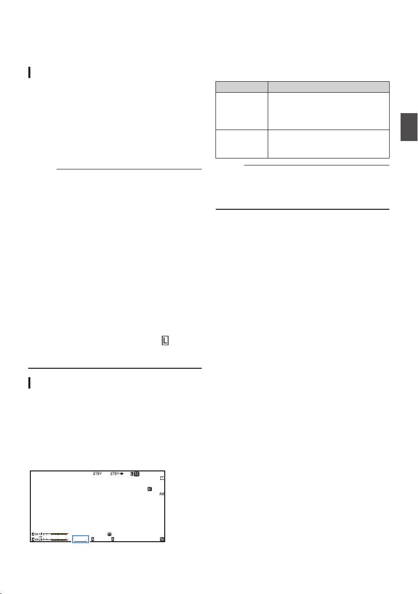
Adjusting the Iris
1
/60
F2. 8
AE
±0
ND1
/64
12 :34 : 56
ISO
102400
00:00 :00.00
5 . 6 f t
B 5600
K
Adjust the
brightness of the subject.
Auto Iris (Automatic Adjustment) Mode
1
2
Memo :
0
0
0
0
0
Manual Iris (Manual Adjustment) Mode
The aperture value (F-number) of the lens can be
set manually.
1
2
aperture of the lens iris according to the
Set the [FULL AUTO] switch to “OFF”.
Press the [IRIS]
button to set to the Auto Iris
mode.
The iris is automatically adjusted according to
the brightness of the object.
A a icon appears on the left side of the lens
aperture value (F-number) during Auto Iris
mode.
Setting the
[FULL AUTO] switch to “ON” to enter
Full Auto mode also activates the Auto Iris
mode. In this case, the Gain, Shutter and White
Balance also enter into Auto mode forcibly.
The iris open/close limit can be set in [Camera
Function
] B [Auto Iris Limit (OPEN)][Auto Iris
Limit (CLOSE)] during Auto Iris.
(A P112 [ Auto Iris Limit (OPEN) ] )
(
A P112 [ Auto Iris Limit (CLOSE) ] )
The control target level (brighter/darker) of the
auto iris can be configured using the crossshaped button (HI) on the side of the camera
recorder unit or in
[Camera Function]
B [AE
Level].
The convergence speed of the auto iris can be
set in the menu.
(A
P111 [ AE Speed ] )
While in the Auto Iris mode, and [AE/FAW
Lock] is set to
“AE” or “AE/FAW”, a
icon
appears on the left side of the lens aperture
value (F-number) during lock operation.
Set the [FULL AUTO] switch to “OFF”.
Press the [IRIS]
button to set to the Manual
Iris mode.
The lens aperture value (F-number) is
displayed.
3
Turn the iris ring on the lens to adjust the
iris manually.
The open F-number of the aperture varies
according to the zoom position.
Wide [W] end
:
F2.8
Tele [T] end : F4.5
F-number Description
Decrease The subject appears brighter.
The focused range becomes
sharper, while the background is
blurred to produce a soft image.
Increase The subject appears darker.
Background of image becomes
focused as well.
Memo :
Pressing the [PUSH AUTO] button in the Manual
0
Iris mode activates the One-push Auto Iris
mode, while holding down the [PUSH AUTO]
button activates the Push Auto Iris mode.
One Push Auto Iris
When the camera recorder is in Manual Iris mode,
press the [PUSH AUTO]
button to adjust the iris
according to the brightness of the object.
Push Auto Iris
When the camera recorder is in the Manual Iris
mode, press and hold the [PUSH AUTO
] button to
change to the Auto Iris mode temporarily. The iris
will be automatically adjusted according to the
brightness of the subject.
About the Iris F-number
Blurry effects due to “small aperture diffraction”
may occur when the diameter of the iris becomes
too small. When this phenomenon occurs, the Fnumber on the screen turns gray to warn you that
the diffraction F-number of the iris has been
exceeded.
recommended to make appropriate use of
You are
ND filters to prevent the F-number from turning
gray.
Shooting
.
Adjusting the Iris
65
Page 66
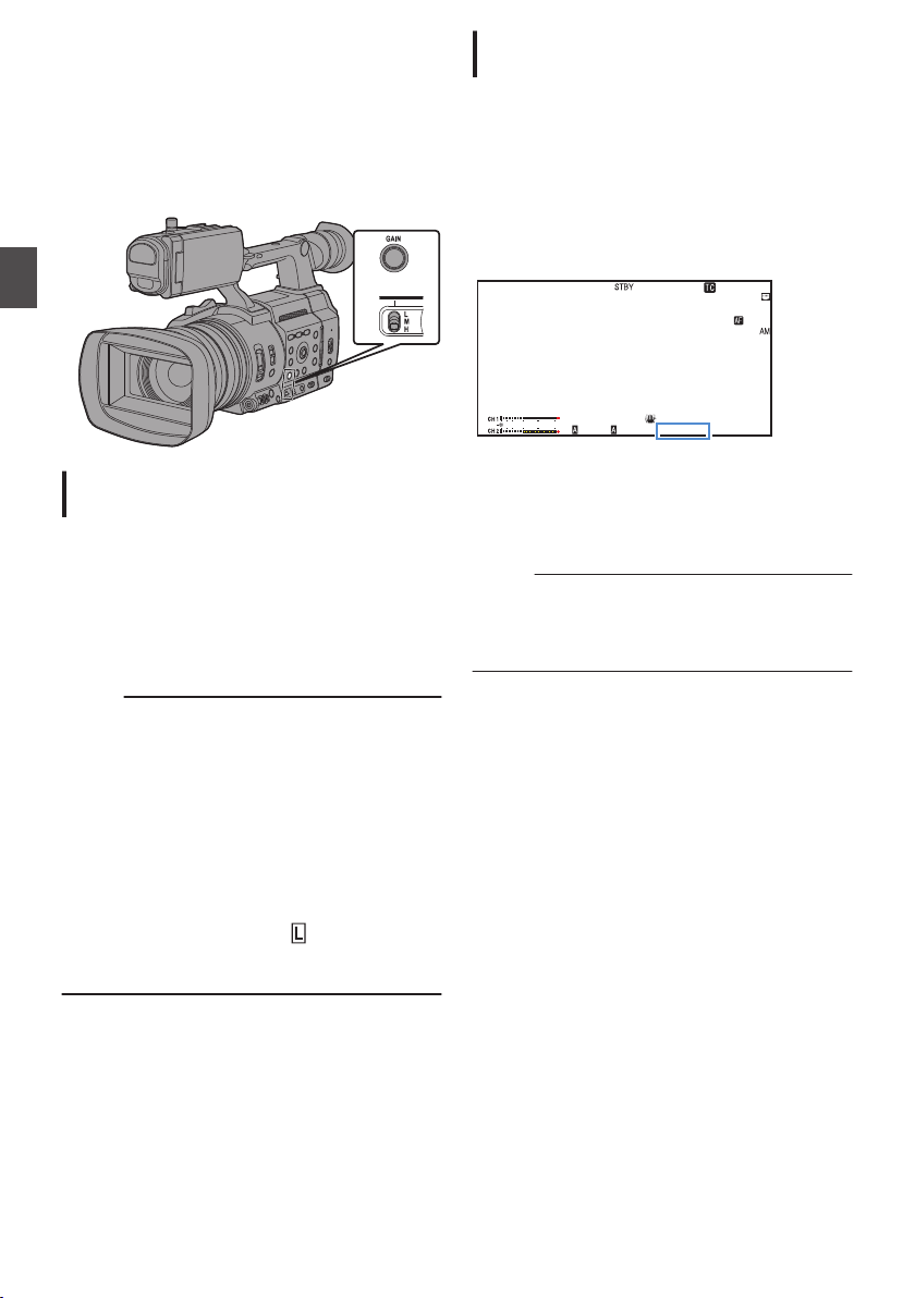
Setting the Gain
1
/60
F2. 8
AE
±0
ND1
/64
12 :34 : 56
ISO
102400
00:00 :00.00
5 . 6 f t
B 5600
K
This function
when there is insufficient illumination on the object.
You can set the gain of the video amplifier
according to the brightness of the object. Select the
setting mode according to your shooting
conditions.
Shooting
electrically boosts the light sensitivity
Manual Gain Mode (Manual Gain
Switching)
1
Set the [FULL AUTO] switch to “OFF”.
2
Press the [GAIN] button
gain mode, followed by selecting the [GAIN
L/M/H] switch
Use the [GAIN L/M/H] switch to display the
0
gain of the selected video amplifier.
The gain level appears on the screen.
0
0
The a
icon on the screen disappears.
to set to the manual
.
Automatic Gain Mode (Automatic Gain
Adjustment)
1
Set the [FULL AUTO] switch to “OFF”.
2
Press the [GAIN] button to set to the AGC
mode.
The gain of the video amplifier is automatically
set according to the brightness of the subject.
A a icon appears on the left side of the gain
value in the AGC mode.
Memo :
Setting the
0
the Full Auto mode also activates the Auto Gain
mode. In this case, the Iris, Shutter and White
Balance also enter into Auto mode forcibly.
The switching operation of the [GAIN L/M/H]
0
switch is disabled in the Full Auto mode.
The upper limit of the gain setting value during
0
AGC operation can be set in [Camera Function]
B [AGC Limit].
(A P111 [ AGC Limit ] )
While in the Auto Gain mode, and [AE Lock] is
0
set to “AE” or “AE/FAW
the left side of the gain value during lock
operation.
[FULL AUTO] switch to “ON” to enter
icon appears on
”, a
.
The default positions of the switch are as
0
follows.
[L] : 0 dB
6dB
[M] :
[H] : 12dB
Memo :
You can
0
change the gain value of each position
in the menu. Increasing the sensitivity causes
the screen to appear grainier.
(A P112 [GAIN L, GAIN M, GAIN H] )
66
Setting the Gain
Page 67
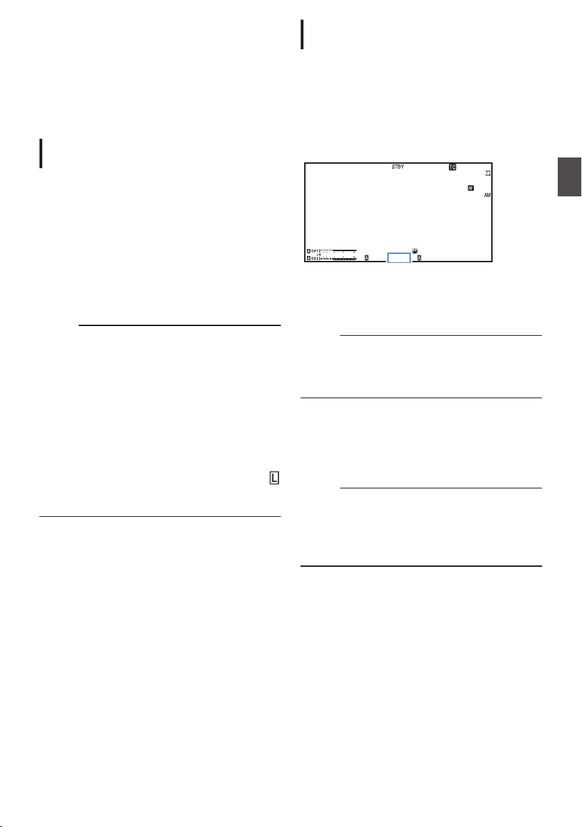
Setting the Electronic
1
/60
F2. 8
AE
±0
ND1
/64
12 :34 : 56
ISO
102400
00:00 :00.00
5 . 6 f t
B 5600
K
Shutter
You can change the shutter speed (time for each
shooting frame) using the electronic shutter
function. Electronic shutter can be adjusted
manually or automatically.
Automatic Shutter Mode (Automatic
Shutter Adjustment)
1
Set the [FULL AUTO] switch to “OFF”.
2
Press the [SHUTTER] button to set to the
Automatic Shutter mode.
0
The a icon appears on the screen.
Automatic Shutter mode adjusts the shutter
0
speed automatically according to the
brightness of the object.
3
Set the controllable range for the Automatic
Shutter in
(A P112
Memo :
Setting the
0
the Full Auto mode also activates the Automatic
Shutter mode. In this case, the Iris, Gain and
White Balance also enter into Auto mode
forcibly.
In the Automatic Shutter mode, switching of
0
shutter speed with the cross-shaped button (J
K) at the side of the camera recorder and
switching
are disabled.
While in the Automatic Shutter mode, and
0
[AE/FAW
icon appears on the left side of the shutter speed
during lock operation.
[Camera Function] B [EEI Limit].
[ EEI Limit ] )
[FULL AUTO] switch to “ON” to enter
of shutter mode with the Set button (R)
is set to “AE” or “AE/FAW”, a
Lock]
Manual Shutter Mode (Manual Shutter
Switching)
1
Set the [FULL AUTO] switch to “OFF”.
2
Press the [SHUTTER] button to set to the
Manual Shutter mode.
0
The a icon on the screen disappears.
0
Use
Set button (R) to switch between the
the
shutter modes and the cross-shaped button
(JK) to switch between the speeds.
.
Switching Shutter Mode
Press the Set button (R) to turn ON/OFF the
shutter.
Memo :
When the shutter is ON, configure the [Camera
0
Function
“Step” is the factory default.
(A P111 [ Shutter ] )
Switching Shutter Speed
When the shutter is ON, use the cross-shaped
button (JK) to configure the shutter speed. The
settable shutter speed range differs according to
the video format setting.
Memo :
0
To display
Rate] to “25p” or “24p” and set [LCD/VF] B
[Display Type] B [Shutter] to “DEG”.
(A P158
A P111 [ Shutter ] )
(
]B[Shutter] item to “Step” or “Variable”.
Shutter in angle (DEG), set [WFrame
[WFrame Rate/ GFrame Rate] )
Shooting
Setting the Electronic Shutter
67
Page 68
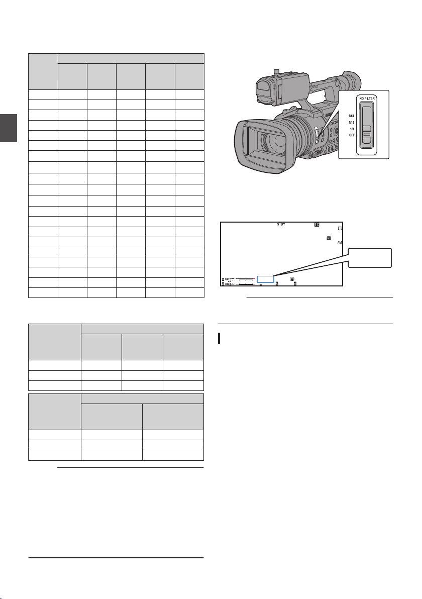
After the shutter speed indication turns white, the
1
/60
F2. 8
AE
±0
ND1/16
12 :34 : 56
ISO
102400
00:00 :00.00
5 . 6 f t
B 5600
K
ND 1/16
setting value can be changed using the crossshaped button (JK).
o
For “Step”
Frame Rate
Shutter
Speed
1/10000
1/4000
1/2000
1/1000
1/500
Shooting
1/250
1/120
1/100
1/12.5 -
1/6.25 -
60p,
60i,
30p
c c c c c
c c c c c
c c c c c
c c c c c
c c c c c
c c c c c
c c c
c c c
1/60
c
*
1/50 1/48 - 1/30
c
1/25 1/24 - 1/15
c
1/12 - -
1/7.5
c
1/6 - -
50p,
50i,
25p
24p
120/60p,
120/30p,
120/24p
c c
c
*
c
c
*
- - - -
c
- - -
c
- - - -
c
- - -
c
- - - -
c
- - -
c
* When the shutter is set to OFF
o
For “Variable”
Frame Rate
Shutter Speed
60p,
60i,
30p
50p,
50i,
25p
Upper limit 1/9860 1/10118 1/9860
(Default value) 1/60.00 1/50.00 1/48.00
Lower limit 1/30.00 1/25.00 1/24.00
Frame Rate
Shutter Speed
120/60p,
120/30p,
120/24p
Upper limit 1/9860 1/10118
(Default value) 1/120.0 1/100.0
Lower limit 1/120.0 1/100.0
Memo :
The operations of the cross-shaped button
0
(JK) and Set button (R) are disabled in the
following cases.
0
During clip preview
0
During display of the formatting confirmation
screen
0
When selecting a face using face detection
0
When
selecting
Meter] set to “Manual”
0
During expanded focus
a photometry area with [Spot
*
c
-
- -
- -
- -
- -
- -
- -
100/50p,
100/25p
100/50p,
100/25p
c
c
*
24p
Setting the ND Filter
Use the ND filter to keep the lens aperture in the
appropriate range.
.
Switch according to the brightness of the object.
When the position on the switch is changed, the
selected
LCD monitor and viewfinder screen.
.
Memo :
recommended to use the ND filter to set the
It is
0
lens aperture to less than F11.
ND Filter Warning Display
In order to adjust the amount of light when you are
shooting at a relatively bright location, the diameter
of the iris may become extremely small, causing
blurry effects to occur as a result.
This phenomenon is known as “small aperture
diffraction”. You can make appropriate use of ND
filters to prevent it from occurring.
This unit displays an ND filter warning when
necessary to prompt you to select an appropriate
ND filter.
1
Set [LCD/VF] B [Display Type
to “Normal + Assist”.
(A P131 [ ND Filter ] )
2
When the iris diameter becomes too small
while adjusting the light intensity, or when
an ND filter is used in a dimly-lit location,
the ND filter display starts blinking.
of the ND filter is displayed on the
position
] B [ND Filter]
Setting the Electronic Shutter
68
Page 69
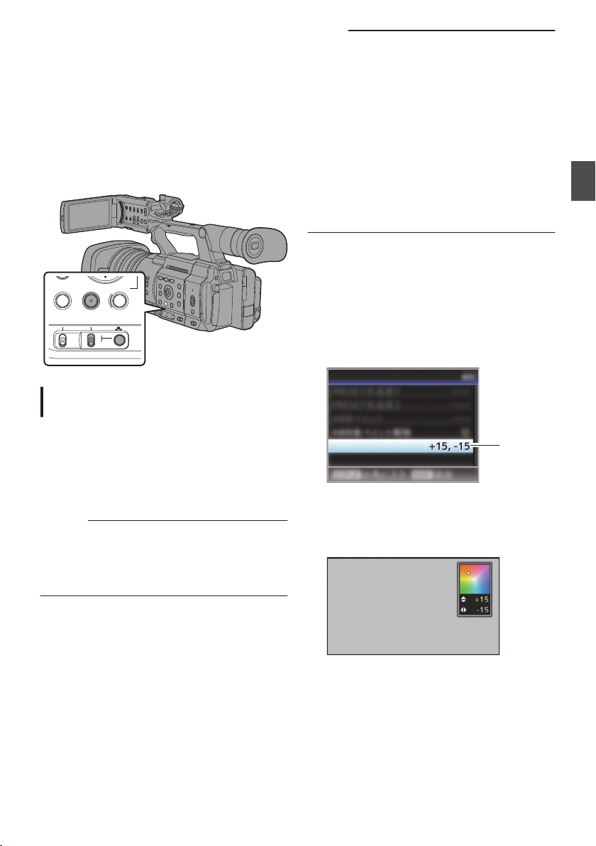
Adjusting the White
SHUTTERWHT BALGAIN
PRESET
A
B
M
L
H
1
FAW Paint
White Balance
B
R
Balance
Adjust the white balance according to the color
temperature of the lighting. You can select the
adjustment mode according to the shooting
conditions.
As the color of the light (color temperature) varies
according to the light source, it is necessary to
readjust the white balance when the main light
source illuminating the subject changes.
.
Automatic White Balance Mode (FAW:
Fulltime Auto White balance)
1
Set the [FULL AUTO] switch to “OFF”.
2
Press the [WHT BAL] button to set to
Automatic White Balance mode.
“FAW” appears on the screen.
0
White balance switching with the
0
B/A/PRESET] selection switch is disabled.
Caution :
The accuracy
0
of [FAW] is inferior to that of [AWB]
(Auto White Balance).
When the power of the camera recorder is
0
turned on with the [FAW] mode selected, it takes
about 15 seconds for the colors to stabilize.
[WHT BAL
Memo :
Setting the
0
[FULL AUTO] switch to “ON” to enter
the Full Auto mode also activates the Automatic
White Balance mode. In this case, the Iris, Gain
and Shutter also enter into Auto mode forcibly.
When [Camera Function] B [User Switch Set] B
0
[AE Lock] is set to “AE/FAW” or “FAW”, the white
balance when the user button that is assigned
with [AE Lock] is pressed can be fixed while in
the Automatic White Balance mode.
(A P117 [ AE Lock ] )
[White Balance]
If
0
is assigned to the user button,
pressing the assigned user button will display
the FAW Paint Adjustment screen.
(A P46 [Assignment of Functions to User
Buttons] )
FAW Paint Adjustment
You can fine-adjust the white balance that was
automatically adjusted.
1
Select [Camera Process] B [White
Balance]
B [FAW Paint] and press the Set
button (R).
The FAW Paint Adjustment screen appears.
.
2
Adjust the R and B values.
Use the cross-shaped button (JK) to adjust R
value and (HI) to adjust B value.
Shooting
.
Adjusting the White Balance
69
Page 70
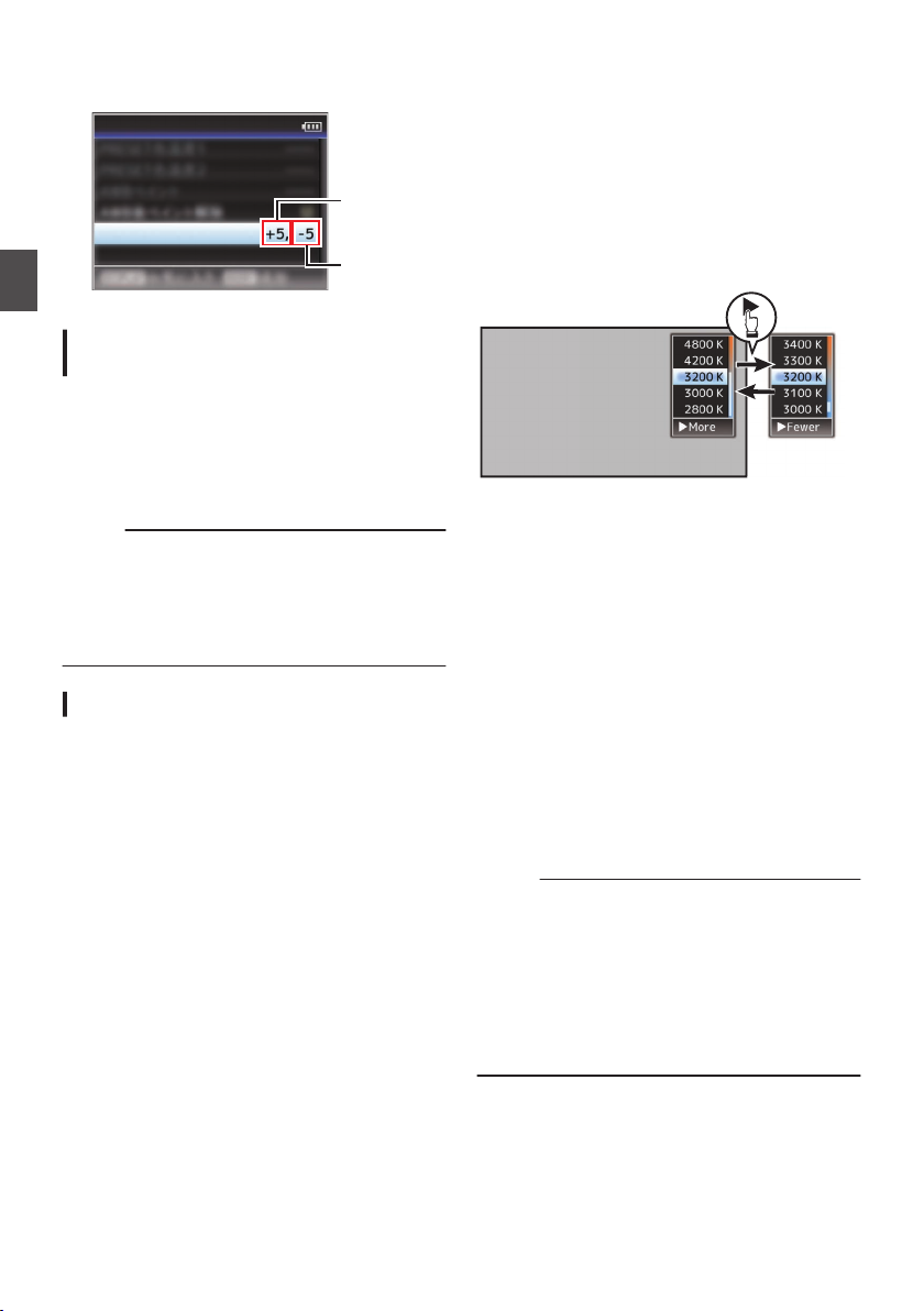
3
B Value
R Value
FAW Paint
White Balance
Color Temperature
Detailed Selection
Screen
Color Temperature Selection Screen
Press the Set button (R).
Returns to the [White Balance] screen.
.
Shooting
Manual White Balance Mode (Manual
Switching)
1
Set the [FULL AUTO] switch to “OFF”.
2
Press the [WHT BAL] button to set to
Manual White Balance mode.
Use the [WHT BAL B/A/PRESET
0
to select “PRESET” (preset mode), “A”
switch
(memory A mode), or “B” (memory B mode).
Memo :
This is fixed at “FAW” when the [FULL AUTO]
0
switch of the camera recorder is set to “ON”.
The FAW
0
(Full Time Auto White Balance) mode
makes automatic adjustments by sampling the
color temperature of the video to obtain the most
appropriate white balance level.
Preset Mode (PRESET)
Two different color temperature settings are
0
registered on this camera recorder. You can
switch between them using the [y] button or
the user button assigned with the “AWB”
function.
Default setting:
[Preset Temp.]
[Alternative Temp.] : 5600K
1
Set the [WHT BAL] switch to “PRESET”.
2
Press the [y] button or the user button
assigned with the
The color temperature switches.
0
(“Preset Temp.”
: 3200K
” function
“AWB
1“Alternative Temp.”)
] selection
Setting the [Preset Temp.] or [Alternative
Temp.] Values
You can change both the color temperature
settings in the Preset mode in the menu.
1
Open the [Preset Temp.
] or [Alternative
Temp.] menu.
Select [Camera Process]
0
B [White Balance]
B [Preset Temp.] and [Alternative Temp.],
and press the Set button (R).
The Color Temperature setting screen
0
appears.
.
2
Select the color temperature.
When selecting from a setting value (Color
0
Temperature Selection screen), use the
cross-shaped
(JK) to select the color
button
temperature.
[Setting Values: 7500K, 6500K, 5600K,
5200K, 4800K, 4200K, 3200K, 3000K,
2800K]
To select detailed values (Color
0
Temperature Detailed Selection screen)
0
Press the cross-shaped button (I) to
display the Color Temperature Detailed
Selection screen.
0
Use the cross-shaped button (JK) to
select a color temperature.
[Setting Values: 2300K to 15000K (in
100K increments)]
Memo :
0
Use the cross-shaped button (I) to switch
between the Color Temperature Selection
screen and the Color Temperature Detailed
Selection screen.
If [White
0
Balance]
is assigned to the user button,
pressing the assigned user button will display
the Color Temperature Selection screen.
(A P46 [Assignment of Functions to User
Buttons] )
Adjusting the White Balance
70
Page 71
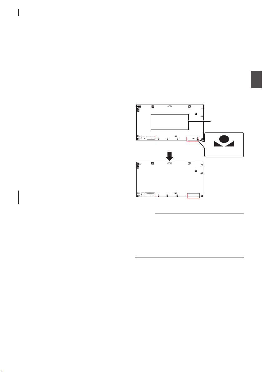
Preset Paint Adjustment
100min
50min
282min
1
/60
F2. 8
AE
±0
ND1
/64
12: 34 : 56
ISO
102400
00:00 :00.00
1080 /30p
120/60fps
5 . 6 f t
B 560 0
K
4030 20 10 0
100min
50min
282min
1
/60
F2. 8
AE
±0
ND1
/64
12: 34 : 56
ISO
102400
00:00 :00.00
1080 /30p
120/60fps
5 . 6 f t
B
4030 20 10 0
Result Display
[AWB] Activating
White Detection
Frame
Blinking
The white balance for [Preset Temp.] and
[Alternative Temp.]
individually or collectively.
1
Select [Camera Process] B [White
Balance
“Common
0
entire color temperature range collectively.
“Individual” configures the settings for the 9
0
types of color temperature individually.
2
Select
Balance
The
adjustment
0
is selected.
The lower color temperature limit of the color
0
temperature range is displayed if “Individual”
is selected. Select the color temperature to
adjust.
In the case of 2300K for example, the target
range is 2300K to 2900K (less than 3000K)
3
Adjust the R and B values.
0
Use the cross-shaped button (JK) to adjust
R value and (HI) to adjust B value.
4
Press the Set button (R).
In
the
0
to the [White Balance] screen.
As for “Individual”, repeat steps 1 to 4 as
0
necessary to configure each color
temperature individually.
can be fine adjusted
] B [Preset Paint Memory].
” configures the settings for the
[Camera Process] B [White
] B [Preset Paint].
screen appears if “Common”
case of “Common”, the display returns
4
Locate a place with similar lighting conditions
as the object to be shot, place a white object
near the center of the screen and zoom in to
fill the screen with white.
5
Press the [
y
] button or the user button
assigned with the “AWB” function
The white detection frame appears when Auto
0
White Balance is activated. Fill the frame with
white completely.
0
While Auto White Balance is starting up, “A
or “B
y
” appears on the screen. (y mark
appears blinking)
After the correct white balance is obtained, an
0
estimated value of the current color
temperature is displayed.
y
”
Shooting
Memory A Mode (A), Memory B Mode
(B)
Set to the white balance saved in Memory A or
0
Memory B.
When the [WHT BAL B/A/PRESET] selection
0
1
A
B
C
2
3
switch is set to
button or the user button assigned with the
“AWB” function executes Auto White Balance.
White balance will be automatically adjusted
and the adjusted value will be saved in Memory
A or Memory B.
Prepare the camera recorder.
Set the [POWER ON/OFF] switch to “ON”.
Set the [FULL AUTO] switch to “OFF”.
Press the [IRIS] button to set to the Auto mode.
Set the [ND FILTER] switch according to the
lighting.
(A P68 [Setting the ND Filter] )
Set the [WHT BAL B/A/PRESET] selection
switch to “A” or “B”.
“A” or “B”, pressing the [y]
.
Caution :
Do not use highly reflective objects, such as
0
metals. Doing so may result in improper white
balance adjustment.
The Auto White Balance function cannot provide
0
optimum white balance with an object outside the
adjustment range, for example when it contains
only a single color or not enough white color.
Adjusting the White Balance
71
Page 72
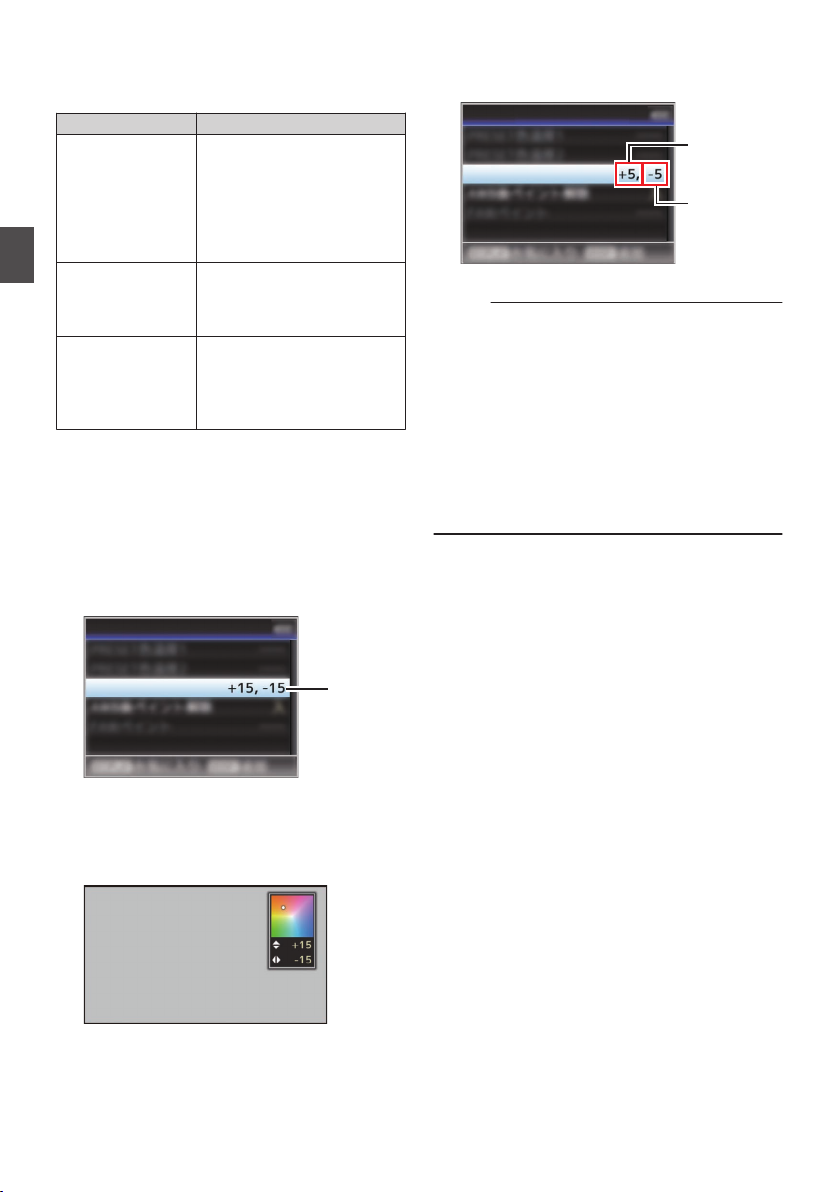
Error Message
1
AWB Paint
White Balance
B
R
B Value
R Value
AWB Paint
White Balance
If the Auto White Balance adjustment is not
correctly completed, one of the following
messages will appear for about 3 seconds.
Message Status
Auto White * NG:
Object
(*A or B)
Displayed when there is not
enough white color on the
object, or when the color
temperature is not suitable.
Use another
adjust the white balance
again.
Auto White * Error:
Shooting
Low Light
(*A or B)
Displayed when the lighting is
dark. Increase the lighting
and adjust the white balance
again.
Auto White * Error:
Over Light
(*A or B)
Excessive illumination.
Displayed
when
too bright. Decrease the
lighting and adjust the white
balance again.
White Paint Adjustment
You can fine-tune the white balance saved in
Memory A or Memory B.
1
Select [Camera Process] B [White
Balance]
B [AWB Paint] and press the Set
button (R).
The White Paint Adjustment screen appears.
white object and
the lighting is
3
Press the Set button (R).
Returns to the [White Balance] screen.
.
Memo :
Executing Auto
0
White Balance will usually clear
the White Paint Adjustment value. But when
[Camera Process] B [White Balance] B [Clear
Paint After AWB] is set to “Off”, values will not
be cleared even when Auto White Balance is
executed.
(A P124 [ Clear Paint After AWB ] )
If
[White Balance]
0
is assigned to the user button,
pressing the assigned user button will display
the AWB Paint Adjustment screen.
(A P46 [Assignment of Functions to User
Buttons] )
.
2
Adjust the R and B values.
Use the cross-shaped button (JK) to adjust R
value and (HI) to adjust B value.
.
72
Adjusting the White Balance
Page 73
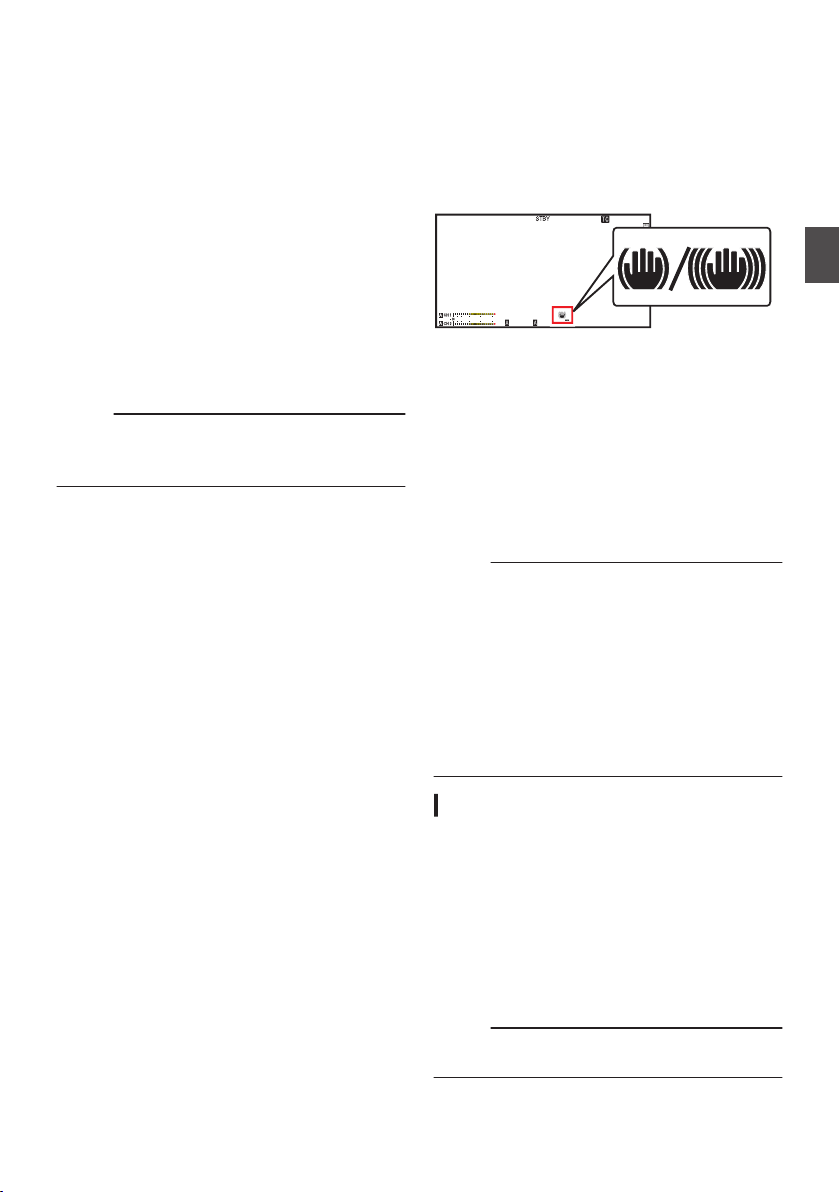
Adjusting the Camera
1
/60
F2. 8
AE
±0
ND1
/64
12: 34 : 56
ISO
102400
00:00 :00.00
5 . 6 f t
B 5600
K
4030 20
10 0
Image
The picture quality of the camera can be set using
the [Camera Process] menu.
As the adjustments are shown on the screen, you
can adjust the values while checking the picture
quality on the camera.
[
Color Space
0
[Gamma]
0
[Detail]
0
[Master Black]
0
[Black Toe]
0
[Knee]
0
[White Clip]
0
[White Balance]
0
[Color Matrix]
0
[Color Gain]
0
[Reverse Picture]
0
Memo :
For details of the respective items, see the
0
[Camera Process]
(A P119 [Camera Process Menu] )
]
menu.
Using the Image Stabilizer
Reduces blurring of images due to camera shake.
1
Check whether the image stabilizer feature
is turned ON or OFF.
If the image stabilizer icon (i/j) does not
appear on the screen display, the image
stabilizer function is OFF.
.
2
Press the [OIS/2] button to turn ON the
image stabilizer feature (when image
stabilizer feature is OFF).
The image stabilizer feature switches between
ON and OFF with every press of the [OIS/2]
button.
OFF:
0
Use this
secured, such as when using a tripod.
ON:
0
Reduces blurring of images due to camera
shake.
Memo :
Select [Camera Function] B [OIS]
0
set the correction level.
(A P111 [ Level ] )
Correction by this feature may not be sufficient
0
when camera shake is too strong.
“OIS” is
0
default.
“OIS” can also be assigned to other user
0
buttons.
(A P46 [Assignment of Functions to User
Buttons] )
setting when the camera recorder is
B [Level] to
assigned to the [OIS/2] button in factory
Shooting
About the Hard Lock Feature
Use this feature when blurry image caused by
camera shake tends to occur due to strong
acceleration.
It can be used to lock the IS (image stabilization)
lens in place.
1
Press the [OIS/2] button to turn off the
Image Stabilizer function
2
Set [Camera Function] B [
Lock] to “On”.
(A P111 [ Hard Lock ] )
Memo :
Camera shake that causes image blur occurs
0
when switching between On and Off.
Adjusting the Camera Image
OIS
] B [Hard
73
Page 74
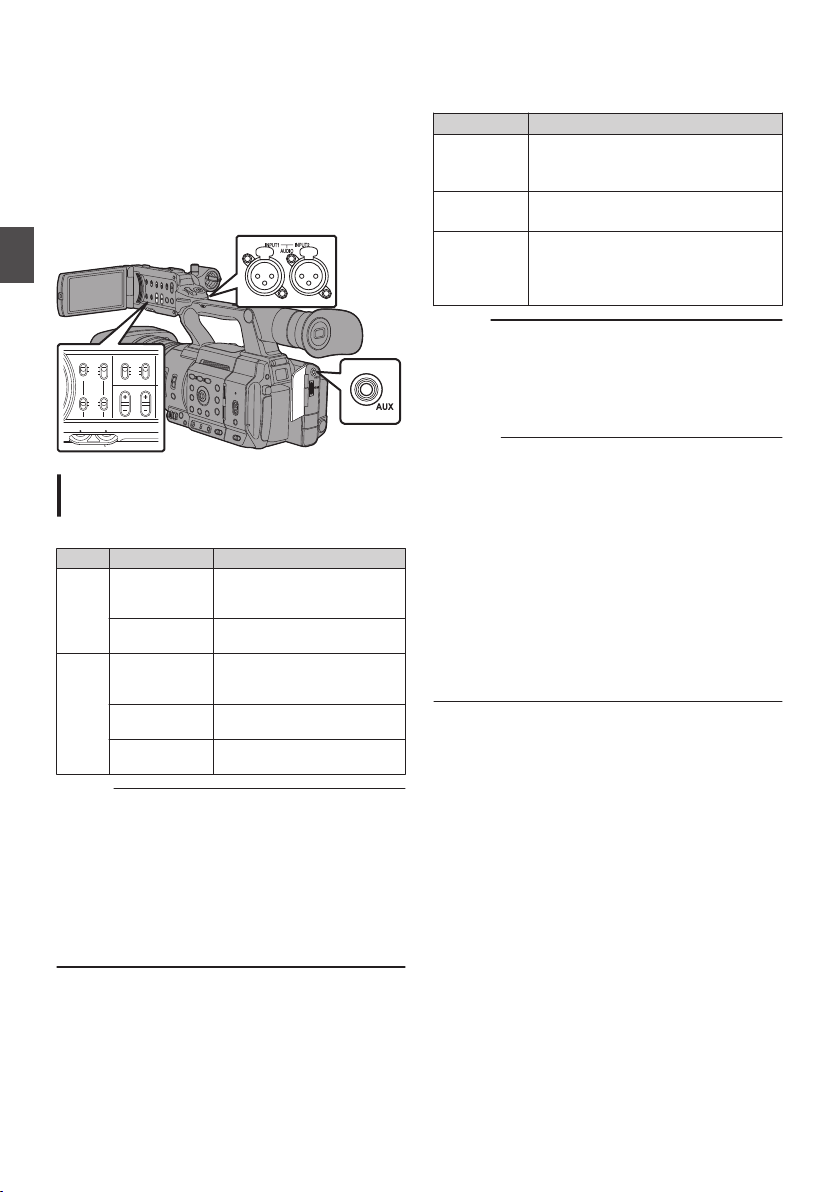
Audio Recording
CH1
INT
INPUT1
INPUT2
AUTO
MANUAL
CH2
INPUT2INPUT1
PEAKINGLCD BRIGHT
CH2CH1
LINE
MIC
MIC
+48V
record audio from the two channels (CH1/
You can
CH2) in synchronization with video images on this
camera recorder.
Select from the options below to record the audio.
Built-in Microphone
0
Microphone connected to
0
Microphone connected to [INPUT1] terminal
0
Microphone connected to [INPUT2] terminal
0
Shooting
.
Selecting Audio to Be Recorded in Each
Channel
Select the audio to be recorded in CH1/CH2.
- Switch Setting Connected Devices
CH1 INT
INPUT1 Microphone connected to
CH2 INT
INPUT1 Microphone connected to
INPUT2 Microphone connected to
Memo :
When “INT” is set, the built-in microphone is
0
disabled if a microphone is connected to the
[AUX] terminal; audio from the microphone
connected to the [AUX] is recorded.
When “INT” is selected, set the reference input
0
level in [A/V Set] B [Audio Set] B [Int. Mic Gain]/
[AUX Gain].
(A P135 [ Int. Mic Gain ] )
(
A P135 [ AUX Gain ] )
Built-in Microphone
0
Microphone connected to
0
[AUX] terminal
[INPUT1
Built-in Microphone
0
Microphone connected to
0
[
[INPUT1] terminal
INPUT2
[
] terminal
[AUX
terminal
]
AUX] terminal
] terminal
Setting Input Channel to [INPUT1]/[INPUT2]
Select the
audio to input to [INPUT1] and [INPUT2]
terminals with the [INPUT1]/[INPUT2] mode
switch.
Setting Description
[LINE] Use this setting when connecting to
an audio
device or other equipment.
The reference input level is +4 dBu.
[MIC] Use this setting when connecting to
a dynamic microphone.
[MIC+48V] Use this setting when connecting to
a microphone (phantom
microphone) that requires a +48 V
power supply.
Memo :
When “MIC” or “MIC+48V” is selected, set the
0
reference input level in [A/V Set] B [Audio Set]
B [Input1 Mic Ref.]/[
(A P135
(
[ Input1 Mic Ref. ] )
A P135 [ Input2 Mic Ref. ] )
Input2 Mic Ref.].
Caution :
When connecting
0
a device that does not require
a +48 V power supply, make sure that it is not
set to the “MIC+48V” position.
When the [INPUT1]/[INPUT2] mode switch is
0
set to “MIC”, make sure that a microphone is
connected to the [INPUT1]/[INPUT2] terminal. If
you increase the recording level when a
microphone is not connected, noise from the
input terminal may be recorded.
When a microphone is not connected to the
0
[INPUT1]/[INPUT2] terminal, set the [INPUT1]/
[INPUT2] mode switch to “LINE” or adjust the
volume with the [CH1]/[CH2] recording level
adjustment knob.
74
Audio Recording
Page 75
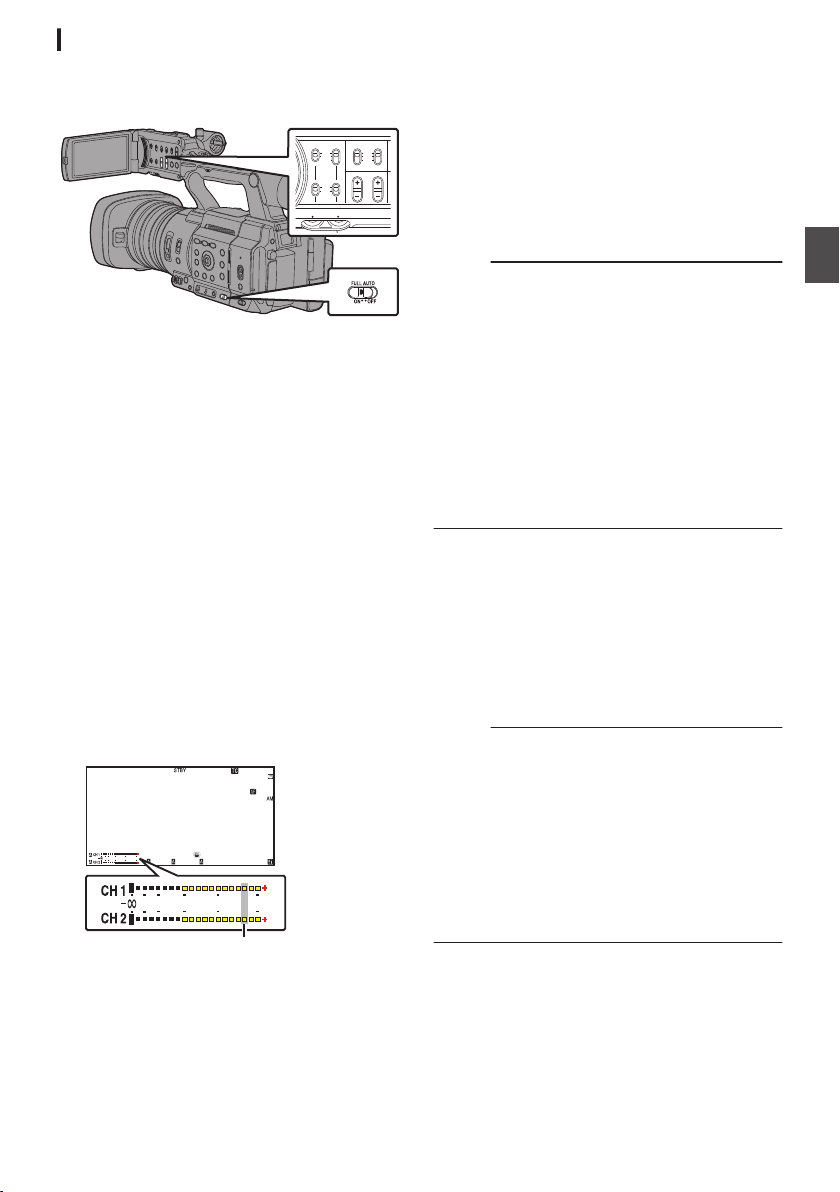
Adjusting Audio Recording Level
CH1
INT
INPUT1
INPUT2
AUTO
MANUAL
CH2
INPUT2INPUT1
PEAKINGLCD BRIGHT
CH2CH1
LINE
MIC
MIC
+48V
1
/60
F2.8
AE
±0
ND1
/64
12: 34 : 56
ISO
102400
00:00: 00.00
5 . 6 f t
B 5600
K
4030 20 10 0
4030 20 10
0
-2dB
You can select to adjust the audio recording levels
for the two channels (CH1/CH2) manually or
automatically.
.
Manual Adjustment Mode (Manual
Adjustment)
Set the [CH1/CH2 AUTO/MANUAL] switch on
0
the camera recorder to “MANUAL” to enter the
manual adjustment mode, and use the
[CH2] recording level adjustment knob to set the
recording level.
You can adjust the level manually during the
0
recording, recording standby, and stop modes.
o
When the input channel is set to “INPUT1”/
“INPUT2”
1
Set the [CH1/CH2 AUTO/MANUAL]
selection switch to “MANUAL
channel to be adjusted manually.
2
Turn the corresponding [CH1]/[CH2]
recording level adjustment knob to adjust
the level.
When [Audio Set] B [Limiter
is set to “Off”,
]
adjust such that the audio level meter does not
light up at -2 dB even for loud sounds.
(A P135 [ Limiter ] )
.
[CH1]/
” for the
o
When the input channel is set to “INT
both [CH1] and [CH2]
1
Set the [CH1 AUTO/MANUAL] selection
switch to
2
Turn the [CH1] recording level adjustment
“
MANUAL”.
knob to adjust the level.
When the built-in microphone and the [AUX]
input terminal are used, the recording levels of
[CH1] and [CH2] are interlocked.
This is also effective when the [CH1 AUTO/
MANUAL] selection switch is set to
[CH2].
Memo :
Select [Limiter], [AGC
0
Response],
[AGC Mode],
or [Int. Mic Separation] in the menu to set the
recording audio.
If [Limiter] is set to other than “Off”, the limiter
0
operates according to the value set.
(A P135 [ Limiter ] )
For the reference level to be recorded to an SD
0
card, set [A/V Set]
B [Audio Set] B [Ref. Level]
to “-20dB”, “-18dB”, or “-12dB”. (common for
CH1/CH2)
(A P135 [ Ref. Level ] )
The operations of the [CH2]
0
recording level
adjustment knob and [CH2 AUTO/MANUAL]
selection switch are disabled.
Automatic Adjustment Mode
Set the [CH1/CH2 AUTO/MANUAL] selection
0
switch to
” or the [FULL AUTO] switch to
“AUTO
“ON” to enter Automatic Adjustment mode. The
audio recording level is set automatically
according to the input level.
When the [FULL AUTO] switch is set to “ON”,
0
mode switching with the [CH1/CH2 AUTO/
MANUAL] selection switch is disabled.
Memo :
]
When [A/V Set
0
B [Audio Set] B [Limiter] is set
to “Off” while in the automatic adjustment mode,
the limiter operates at -6dBFS.
(A P135 [ Limiter ] )
When
[A/V Set]
0
B [Audio Set] B [Audio On FULL
AUTO] is set to “SW Set”, you can switch the
audio recording mode with the [CH1/CH2
AUTO/MANUAL] selection switch on the
camera recorder even when the [FULL AUTO]
switch is set to “ON”.
(A P137 [ Audio On FULL AUTO ] )
” for
Shooting
Audio Recording
75
Page 76
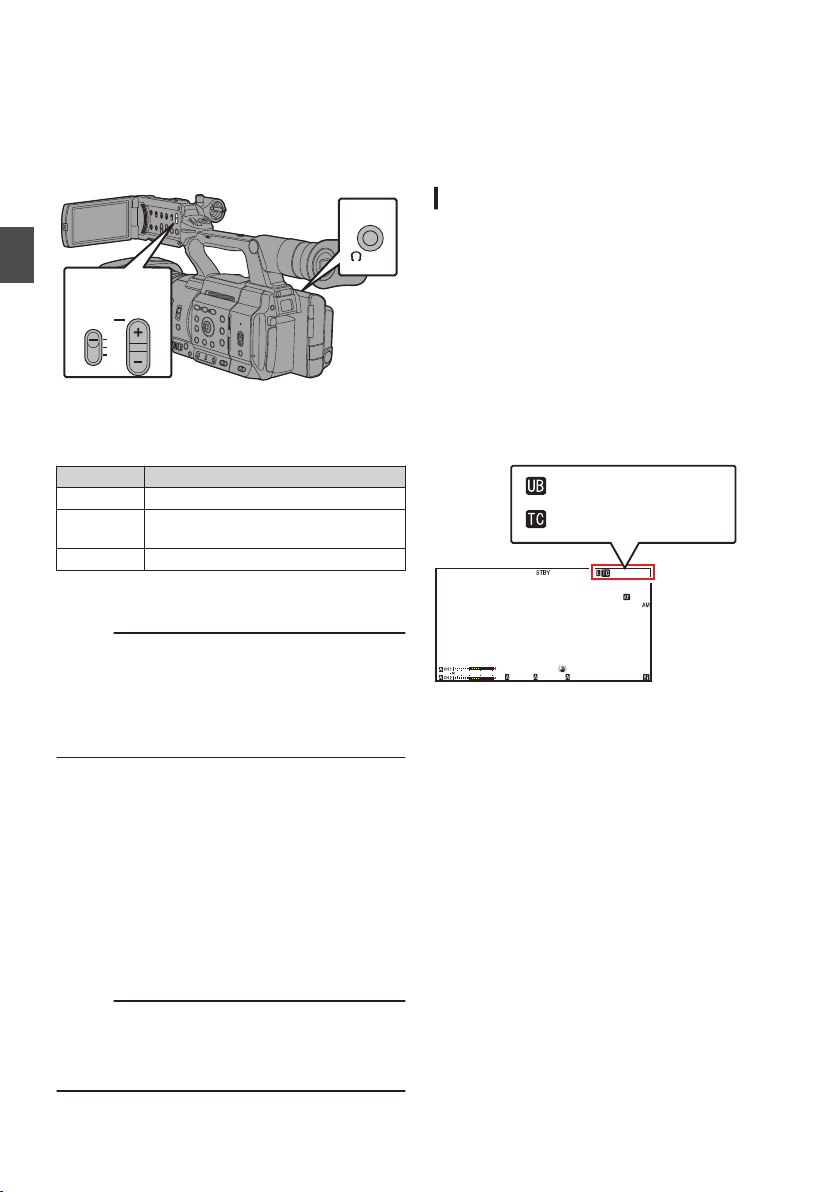
Monitoring Audio Sound
MONITOR
CH1
BOTH
CH2
32
1
1
/60
F2. 8
AE
±0
ND1
/64
12: 34 : 56
ISO
102400
00:00 :00.00
5 . 6 f t
B 5600
K
4030 20 10 0
00H 00M00S 00F
AB CD EF 89
During Recording Using a
Headphone
You can check the recorded audio using
headphone.
Shooting
.
1
Connect the headphone.
2
Select the channel to monitor with the
[MONITOR
Setting Description
[CH1] Outputs the audio recorded in [CH1].
[BOTH] Outputs the audio recorded in
[CH2] Outputs the audio recorded in [CH2].
3
Use the [MONITOR +/-] button to
monitor volume.
Memo :
Audio during recording is not output from the
0
monitor speaker.
Warning tone is output when there is an
0
abnormality in
battery is low.
(A P253 [Warning Tone] )
selection switch.
]
[CH1/CH2].
the camera recorder or when the
adjust the
Time Code and User’s Bit
Time code
video in this camera recorder.
The time code and user’s bit are displayed on the
viewfinder and LCD monitor during playback or
recording. (Display screen)
Displaying Time Code and User’s Bit
The time code and user’s bit are displayed on the
viewfinder and LCD monitor during playback or
recording.
The display
1
2
.
and user’s bit data are recorded with the
differs according to the menu settings.
Set [LCD/VF] B [Display On/Off] B [TC/UB]
to “On
”.
(A P131 [Display On/Off Item] )
Set [LCD/VF
] B [Display Type] B [TC/UB].
When “TC” or “UB” is selected, time code or
user’s bit data is displayed respectively on the
display screen.
(A P
130 [ TC/UB ] )
Selecting Audio Output Method When the
[MONITOR]
Selection Switch Is Set to “BOTH”
When a stereo type earphone jack is connected,
perform the following setting to output stereo
sound.
1
Set the [MONITOR] selection switch to
“BOTH”.
2
Set [A/V Set] B [Audio Set] B [Monitor] to
“Stereo”.
(
A P136 [ Monitor ] )
Memo :
You can set the volume of the warning tone in
0
[A/V Set]
B[Audio Set]B[Alarm Level]. (“Off”/
“Low”/“Middle”/“High”)
(A P137 [ Alarm Level ] )
Monitoring Audio Sound During Recording Using a Headphone
76
Page 77

Time Code Operation Mode
Set the time code operation in [TC/UB] B [TC
Generator].
(A P125 [ TC Generator ] )
Setting Description
Free
Run(NTP)
Free
Run(GPS)
L
Free Run
(Ext)
Free Run The time code operates in the run
Rec Run The time code operates in the run
Regen The time code operates in the run
Memo :
When [System] B [Record Set
0
set to “Interval Rec” or “Frame Rec”, and [TC
Generator] is set to “Free Run”, “Free Run
(Ext)” or “Free Run(NTP)”, “Rec Run” is
activated.
When [System] B [Record Set]
0
Format] B [System] is set to “High-Speed”, and
[TC Generator] is set to “Free Run”, “Free Run
(Ext)” or “Free Run(NTP)”, “Rec Run” is
activated.
Time code information can be
synchronized with the time
information obtained
server.
Time code information can be
synchronized with the date/time
information acquired from the
GPS.
This mode synchronizes another
camera recorder connected to the
[TC] terminal. The time code
operates in the run mode at all
times regardless of the recording
status.
It continues to run even when the
power of the camera recorder is
turned off.
all times regardless of the
at
mode
recording status.
It continues to run even when the
power of the camera recorder is
turned off.
mode during recording. It
continues
recorded clips as long as the SD
card is not replaced. If the SD card
is removed and recording is made
on another card, time code will be
recorded on the new card from
where it was left off in the previous
card.
mode during recording. When the
SD card is replaced, the last time
code recorded on the card is read
and recorded
the time code continues in running
order.
to
(A P78 [Setting Time Code] )
from the NTP
run in the order of the
on a new card so that
] B [Rec Mode] is
B [Record
Setting Time Code Generator
Presetting the Time Code
Time code and user’s bit data generated from the
internal time code generator are recorded.
This section describes how to set [TC/UB]
Preset].
(A P125 [ TC Preset ] )
Memo :
When [System]
0
Format] B [WFrame Rate] is set to “50p”, “50i”,
“25p” or “24p”, setting for “Drop” will be disabled.
(A P
158 [WFrame Rate/ G
You can
0
the [TC/UB] menu screen.
(A P79 [Setting Time Code without Opening
the Menu] )
Required Settings Before Preset
1
Set [TC/UB] B [TC Generator
or “Free Run”.
(A P125 [ TC Generator ] )
[Rec Run]:
0
Preset data in the time code generator
operates
Set this when recording continuous time
code in connecting frames.
[Free Run]:
0
Time code starts to operate in run mode from
the preset time in the time code generator.
B [Record Set] B [Record
Frame Rate] )
configure the setting without accessing
in run mode during recording mode.
B [TC
to “Rec Run”
]
Shooting
Time Code and User’s Bit
77
Page 78
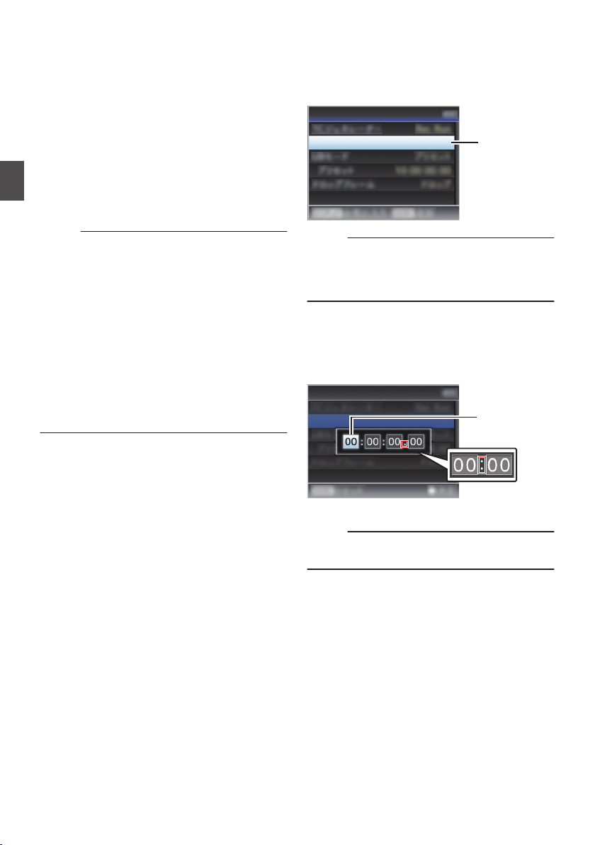
2
1
TC Preset
00:00:00:00
TC/UB
During drop frame
During non-drop
frame
Cursor
TC Preset
00:00:00:00
TC/UB
Select the framing mode for the time code
generator (only
when the frame rate setting
is “60” or “30”).
To configure the setting, go to [TC/UB] B [Drop
Frame].
(A P126 [ Drop Frame ] )
[Drop]:
0
Sets
the run mode of the time code generator
to drop frame mode. Use this setting when
placing emphasis on the recording time.
[Non Drop]:
0
Sets the run mode of the time code generator
to non-drop frame mode. Use this setting
Shooting
when placing emphasis on the number of
frames.
Memo :
Drop frame/non-drop frame mode
When [System] B [Record Set] B [Record
0
Format] B [Frame Rate
is set to “60p”, “60i”, or
]
“30p”, the actual number of frames per second
is approximately 59.94 (29.97). However, the
time code processing standard is “60p”, “60i”, or
“30p” frames. To make up for the frame number
discrepancy, the drop frame mode (Drop) drops
the 00 frame and 01 frame every minute except
for minutes that are multiples of 10. However, in
the case of “60p”, the 00, 01, 02 and 03 frame
are dropped.
0
The
non-drop
frame mode (Non Drop) does not
drop frames and ignores the discrepancy with
the actual time.
Setting Time Code
1
Select [TC/UB] B [TC Preset
and press the
]
Set button (R).
(A P125
The
.
[ TC Preset ] )
[TC Preset] screen appears.
Memo :
When [TC/UB] B [TC Generator] is set to
0
“Regen”, the parameter is displayed as
“<Regen>” and cannot be selected.
(A P125 [ TC Generator ] )
2
Set the time code (hour, minute, second,
frame).
Use the cross-shaped button (HI) to place the
cursor at the item to set, then use the crossshaped button (JK) to change the values.
78
Setting Time Code Generator
.
Memo :
Press the [OIS/2] button to reset each digit to “0”.
0
The cursor moves to the time digit (left).
3
Check the values and press the Set button
(R).
The time code is set and the screen returns
0
to [TC/UB].
To cancel the setting, press the [CANCEL]
0
button.
4
Press the [MENU/THUMB] button.
Returns to the normal screen.
Page 79
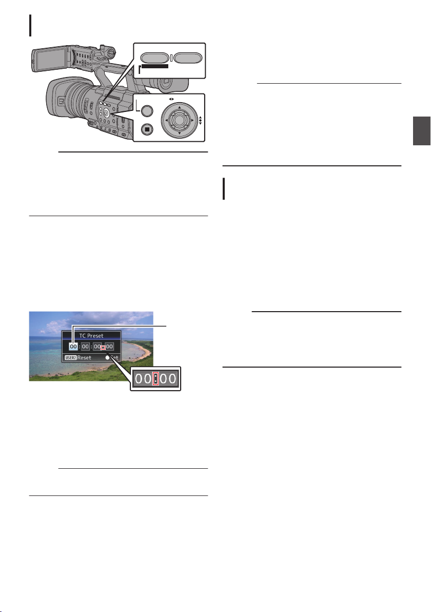
Setting Time Code without Opening the
CANCEL
MENU/THUMB
AE LEVEL
FOCUS ASSIST/1 OIS / 2
TIME CODE
During drop frame
During non-drop frame
Cursor
Menu
.
Memo :
Settings
0
0
[TC/UB] B [TC Generator] has been set to
“Regen”.
0
Menu screen is displayed.
0
The camera recorder is not in the Camera
mode.
Setting Time Code
1
Set [TC/UB] B [TC Generator] to a value
other than “Regen”.
(A P125 [ TC Generator ] )
2
Hold down the
press the [
The [TC Preset] setting screen appears.
be made in the following cases.
cannot
[MENU/THUMB] button and
FOCUS ASSIST/1] button.
4
Check the values and press the Set button
(R).
The time code is set and the screen returns
0
to the normal screen.
To cancel the setting, press the
0
[CANCEL]
button.
Caution :
When the
0
camera recorder is switched to Media
mode during editing, editing will be canceled
and the screen will close.
When editing the time code, operation of the
0
buttons that are set in [Camera Function] B
[User Switch Set] is disabled. [OIS/2] functions
as the number reset button.
(A P116 [User Switch Set Item] )
Recording Time Code in Continuation of
the Recorded Time Code on SD Card
This camera recorder is equipped with the time
code reader.
1
Set [TC/UB] B [
When the camera recorder enters from
0
TC Generator
recording standby mode to recording mode,
it reads the time code already recorded on
the SD card and records the new time code
in continuation of that value.
The same data as the user’s bit already
0
recorded on the SD card is recorded.
Memo :
When [TC/UB] B [TC Generator
0
“Regen”, the framing mode of the time code
follows the settings in
[TC/UB] B [Drop Frame]
instead of the clip settings.
(A P126
[ Drop Frame ] )
] to “Regen”.
] is set to
Shooting
.
3
Set the time code (hour, minute, second,
frame).
Use the cross-shaped button (HI) to place the
cursor at the item to set, then use the crossshaped button (JK) to change the values.
Memo :
Press the [OIS/2] button to reset each digit to “0”.
0
The cursor moves to the time digit (left).
Setting Time Code Generator
79
Page 80
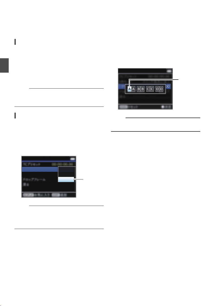
Setting the User’s Bit
1
TC/UB
UB Mode
Preset
Time
Preset
Date
TC/UB
Cursor
You can add the date, time or an 8-digit
hexadecimal number as the user’s bit to the
recorded image.
Selecting a Recording Mode
Recording date/time information to the user’s
bit
1
Set [TC/UB] B [UB Mode]
“Time”, and press the Set button (R).
Shooting
(A P126
The date or time information is recorded to the
[ UB Mode ] )
user’s bit.
Memo :
When “Date” or “Time”
0
as “-” and cannot be set.
“Time” is displayed in the 24-hour format.
0
to “Date” or
is set, [Preset] appears
2
Select [
TC/UB] B
“Preset” and press the Set
button (R).
The [Preset] setting screen appears.
3
Use the cross-shaped button (HI) to
the cursor at the item to set, then use the
cross-shaped button (JK) to change the
values.
Numbers between 0 and 9 or alphabets
between A
and F can be specified for the user’s
bit.
place
Presetting the User’s Bit
Recording arbitrary information (8-digit
hexadecimal) to the user’s bit
1
Set [TC/UB] B [UB Mode
press the Set button (R).
(A P
126 [ UB Mode ] )
.
Memo :
When [TC/UB] B [TC Generator] is set to
0
“Regen”, the parameter is displayed as
“<Regen>” and cannot be selected.
(A P125 [ TC Generator ] )
] to “Preset”, and
.
Memo :
Press the [OIS/2
0
] button to reset each digit to
“0”. The cursor moves to the left.
4
Check the values and press the Set button
(R).
0
The
bit is set and the screen returns to
user’s
[TC/UB].
To cancel the setting, press the [CANCEL]
0
button.
5
Press the [MENU/THUMB] button.
Returns to the normal screen.
80
Setting the User’s Bit
Page 81
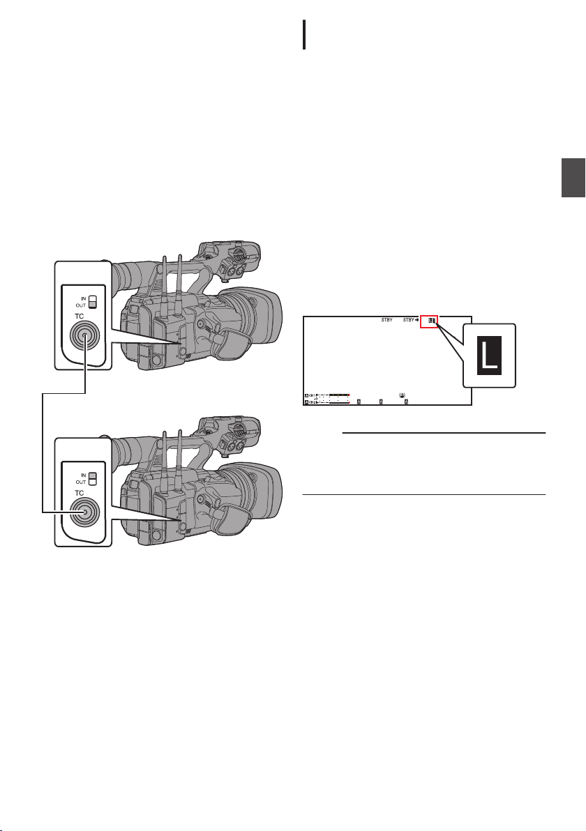
Synchronizing Time Code
[IN]
Slave Device (This Camera Recorder)
[OUT]
Master Device
1
/60
F2. 8
AE
±0
ND1
/64
12 :34 : 56
ISO
102400
00:00 :00.00
5 . 6 f t
B 5600
K
4030 20 10 0
on Another Camera
This camera
input/output terminal ([TC] terminal).
Connect another camera recorder to the [TC]
terminal and synchronize to the time code.
1
Connect the [TC] terminal of the master
device with the [TC]
device.
Set the [TC IN/OUT] switch of the master device
to “OUT”, and the [TC IN/OUT] switch of the
slave device to “IN”.
recorder is equipped with a time code
terminal of the slave
Settings and Operation of the Camera
Recorder
1
Set to Camera mode.
(A P24 [Operation Modes] )
2
Set [TC/UB]
Slave device:
0
Select “Free Run (Ext)”.
Master device:
0
Select “Free Run
3
Set LCD monitor or viewfinder to Display
screen.
4
Set the master device and run the time
code.
When the built-in time code generator is
0
synchronized with the external time code
data
up.
When time code is not synchronized or time
0
code input is not available, the Z icon goes
out.
.
Memo :
The built-in time code generator will continue
0
operation even when the master device is
disconnected after synchronization.
User’s
0
B [TC Generator
as follows.
]
”.
the Z icon on Display screen lights
input,
bit
will become data in the master device.
Shooting
.
Synchronizing Time Code on Another Camera
81
Page 82
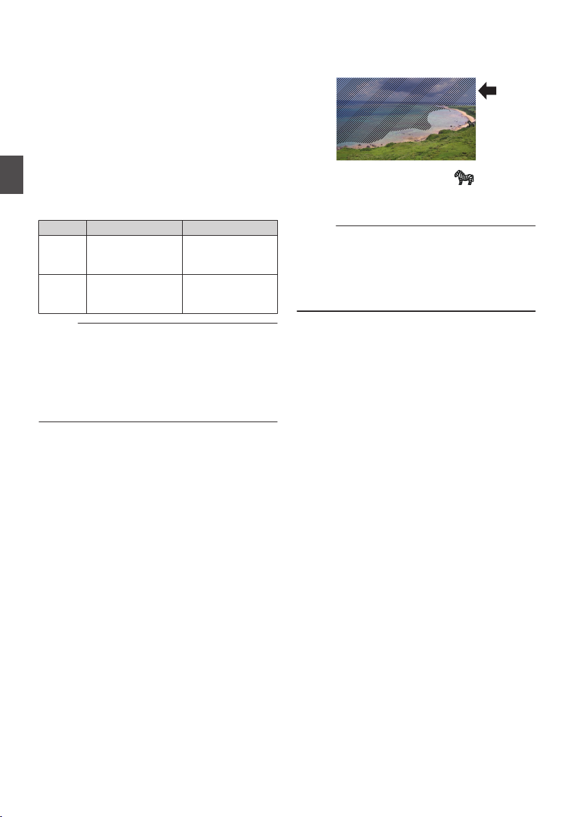
Setting Zebra Pattern
When the luminance level range for displaying
zebra patterns is specified, diagonal lines (zebra
pattern) are displayed at areas with the specified
luminance levels during shooting.
1
Set [LCD/VF] B [Shooting Assist]
to “On”.
(A P128 [ Zebra ] )
2
Specify the brightness (luminance) level
range for displaying zebra pattern.
Shooting
Specify the upper and lower limits of the
luminance level in [
Assist] B [Zebra] B [Top] and [Bottom].
Item Settings Options
Top Upper luminance
Bottom Lower luminance
Memo :
0
limit for displaying
[Zebra]
limit for displaying
[Zebra]
The timing to detect the zebra pattern display
configured only when “J-Log1” or “HLG”
can be
is selected in [Color Space] and “Cam” or “Cam
+ Return” is selected in [Convert to ITU709].
(A P119 [ Color Space ] )
(A P127 [ Convert to ITU709 ] )
(A P128 [ Detect ] )
LCD/VF] B [Shooting
5%, 10% to 95%,
98%, 100%, Over
0%, 5% to 95%,
98%, 100%
B [Zebra]
3
Display the zebra pattern.
Press the [ZEBRA/5] button
pattern in the specified range.
.
During zebra pattern display, (zebra icon)
is displayed on the display screen in Camera
mode.
Memo :
“Zebra” is assigned to [ZEBRA/5]
0
factory default.
“Zebra” can also be assigned to other user
0
buttons.
(A P46 [Assignment of Functions to User
Buttons] )
to display the zebra
button in
Setting Zebra Pattern
82
Page 83
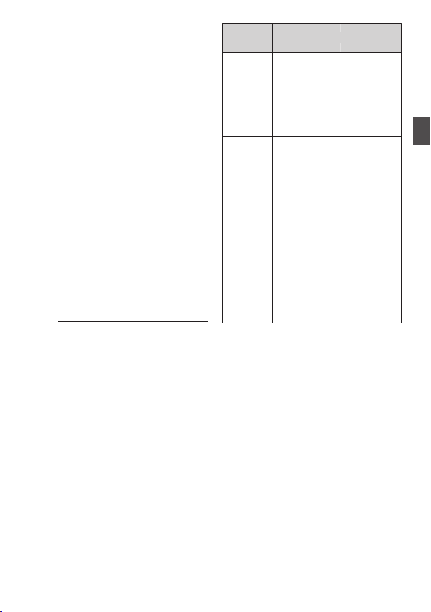
Setting Spot Meter
The brightness of the object during shooting is
displayed.
This function is useful when setting video or stage
lighting or when specifying camera exposure.
A cursor
(%) of that location are displayed in the images
shown on the LCD monitor or viewfinder screen.
Memo :
1
indicating the location and the brightness
Zebra patterns display the brightness of output
0
video signals.
(A P82 [Setting Zebra Pattern] )
This
0
of input images from the lens without depending
on image processing such as gamma curve.
When [Color Space] is set to a value other than
0
“HLG” and “J-Log1”, the dynamic range of the
camera recorder is max. 400% and a brightness
range of 0% to 400% is displayed.
The value of the spot meter changes according
0
to the setting of [LCD/VF] B [Convert to
ITU709]/[White Level] when [Color Space] is set
to “HLG”.
When [Color Space] is set to “HLG” and
[LCD/VF] B [Convert to ITU709]/[White Level] is
set to “72.5%”, the dynamic range of the camera
recorder is max. 458% and a brightness range
of 0% to 458% is displayed.
When [
0
dynamic range of the camera recorder is max.
800% and a brightness range of 0% to 800% is
displayed.
Spot meter
0
display range.
Select one of the following from [Camera
Function]
Meter].
(A P
allows you to check the brightness
function
Color Space
B [User Switch Set] B [Spot
117 [ Spot Meter ] )
] is set to “J-Log1”, the
may not be consistent with the zebra
Item Settings
Max & Min
Max Displays the
Min Displays the
Manual Displays the
2
Assign the “Spot Meter” function to any of
the user buttons.
(A P
Buttons] )
3
Press
“Spot Meter”.
The operation switches as below when the
button is pressed.
Displays the
brightness (%)
and positions of
the brightest and
darkest areas in
the screen.
Frames may also
be stopped at the
current positions.
brightness (%)
position
and
brightest area in
the screen.
Frames may also
be stopped at the
current positions.
brightness (%)
position
and
darkest area in the
screen. Frame
may also be
stopped at the
current positions.
brightness (%) of
the specified
position.
46 [Assignment of Functions to User
the user button that is assigned with
Color of Frame
Green
of the
Yellow
of the
Green
(Blinks in green
when specifying
the position)
Indicating the
Position
Max: Green
0
Min: Yellow
0
Shooting
Setting Spot Meter
83
Page 84
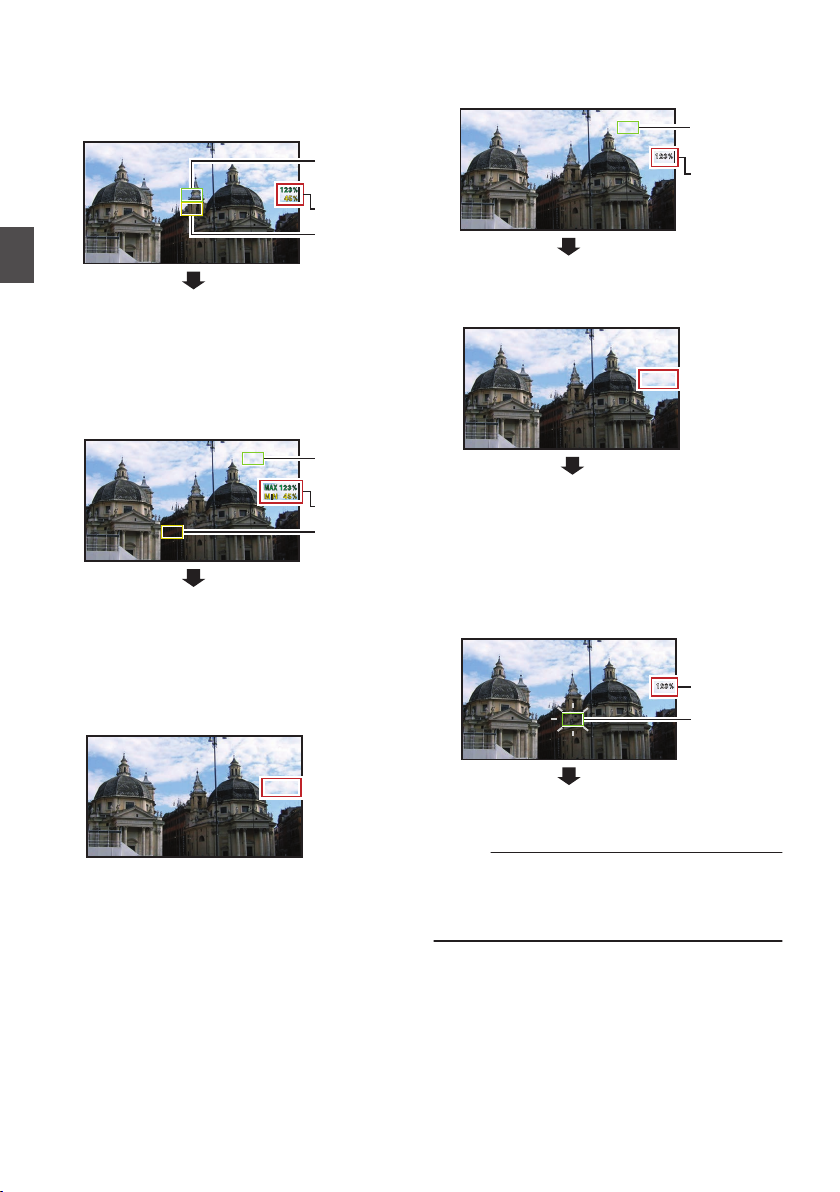
When [Max & Min]/[Max]/[Min] is selected
Cursor
Cursor
Brightness
Indication
(Yellow)
(Green)
(Min: Yellow)
Cursor
(Max: Green)
Cursor
Brightness
Indication
Cursor
(Green)
Brightness
Indication
(Blinks in
green)
Cursor
Brightness
Indication
The cursors appear according to the setting
A
when the button is pressed.
Green and yellow frames appear, and the
brightness levels of these areas are displayed.
Shooting
.
B Hold down the button in the state in A, the
positions of the brightest (Max) and darkest
(Min) areas in the screen are automatically
detected with regard to the changes of the
object, and the brightness level of these areas
are displayed.
.
C Pressing the button in the state in B stops the
automatic position detection. The frames are
fixed at the stopped positions and the
brightness levels are displayed.
By pressing the button, the cursors and
D
brightness indication disappear.
When [Manual] is selected
The brightness of the cursor position is
A
displayed when the button is pressed.
.
By pressing the button, the cursors and
B
brightness indication disappear.
.
C Hold down the button in the state in A or B, the
cursor blinks in green.
Move the cursor with the cross-shaped button
(JKHI) to specify the position to display the
brightness.
When you decide on the position, press the Set
button (R) to confirm.
.
Setting Spot Meter
84
.
Frames are fixed at the stopped positions and
D
the brightness is displayed.
Memo :
When moving the cursor position, [Shutter]
0
Level] control is disabled.
When the brightness is 0 % in the entire screen,
0
the frame is fixed in the center.
/[AE
Page 85
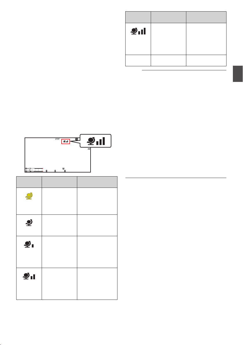
Acquiring Positioning
1
/60
F2. 8
AE
±0
ND1
/64
12 :34 : 56
ISO
102400
00:00 :00.00
5 . 6 f t
B 5600
K
4030 20 10 0
Information by GPS A
L
This camera recorder comes with a built-in GPS
function. The GPS function is able to record the
positioning information.
During playback,
information on the playback screen.
(A P101 [Playing back] )
1
Set [System] B [
(A P155 [ GPS A
0
Positioning starts when the H icon on the
display screen starts blinking.
0
After positioning is complete, the H icon
switches to a solid light and records the
positioning information during shooting.
The
0
according to the condition of signal reception
from the GPS satellite.
.
Display
.
(Yellow)
.
(Blink)
.
.
you can also display the recorded
to “On”.
GPS]
L ] )
icon that appears on the screen changes
Reception
Status
[GPS] is set to
“On”, but signal
cannot be
received
Positioning Status
GPS signal cannot
be received. UTC
and positioning
information cannot
be obtained.
GPS search in
progress
UTC information
can be obtained,
but not positioning
information.
GPS reception
in progress
(signal strength:
weak)
Receiving weak
GPS signal. UTC
and positioning
information can be
obtained and
recorded.
GPS reception
in progress
(signal strength:
medium)
Receiving GPS
signal. UTC and
positioning
information can be
obtained and
recorded.
Display
.
Reception
Status
GPS reception
in progress
(signal strength:
strong)
Positioning Status
Receiving strong
GPS signal. UTC
and positioning
information can be
obtained and
recorded.
(No
display)
GPS function is
turned off
The [GPS] item is
set to “Off”.
Memo :
If positioning cannot be performed after waiting
0
for several minutes, this means GPS reception
is poor, and there is difficulty in receiving data.
Move to an open place with no obstructions.
Otherwise, GPS
information will not be recorded
when shooting is performed.
Signal may not be received depending on
0
circumstances such as locations that are
indoors or surrounded by tall buildings, or the
geographical conditions.
Precision error may occur in the position
information depending on the conditions of
reception.
Even when positioning is in progress,
0
information may be disrupted depending on the
condition of signal reception.
When [A/V Set] B [Video Set] B [SDI OUT] B
0
[Resolution] is set to “1080p”, configuring
[System] B [GPS] to “On” changes the setting to
“1080i”.
Shooting
Acquiring Positioning Information by GPS A L
85
Page 86

Viewing Recorded Videos
Immediately (Clip
You can check (review) the last recorded video clip
on the screen.
However, the video clip cannot be played back if
the settings of the camera recorder are different
from the video format (Resolution/Frame Rate/Bit
Rate/SD Aspect) of the clip.
(A P157 [WResolution/ GResolution] )
(A P158 [WFrame Rate/ GFrame Rate] )
(A P158 [WBit Rate/ GBit Rate] )
(A P159 [ SD Aspect ] )
Shooting
Memo :
To use
0
1
Memo :
0
0
this function, assign “Clip Review” to any
of the user buttons.
Press the user button assigned with the
“Clip Review”
(“STBY” is displayed).
Playback of the configured section starts.
The video clip is played back according to the
setting in [Camera Function] B [User Switch
Set] B [Clip Review]. By default setting (Last
5sec), the last 5 seconds of the clip is played
back.
(
A P117
When playback is complete, the camera
recorder exits Clip Review and returns to
“STBY” (recording standby) mode.
function during standby
[ Clip Review ] )
Review)
Caution :
During Clip Review, only the [CANCEL] and
0
] buttons are enabled.
[REC
Press the [CANCEL] button to cancel clip review
and return to “STBY” (recording standby) mode.
Press the [REC] button to cancel clip review and
enter recording mode. It will take some time to
start recording after the button is pressed.
When the last clip is less than 5 seconds, the
0
whole clip is played back.
Only video clips in the currently selected slot can
0
be reviewed.
When there are no clips in the selected slot, Clip
0
Review function is disabled.
Clip Review is unavailable when Clip
0
Continuous Rec is paused (“STBYL”, yellow
text). To operate Clip Review, use the
[CANCEL] button to set to “STBYL” (white text)
first.
(A P
92 [Clip Continuous Rec] )
Clip Review is unavailable when the camera
0
recorder is
and the equipment is in recording state.
Clip Review is unavailable when operating View
0
Remote via network connection.
(A P204 [Camera Control Function] )
Clip Review does not function during live
0
streaming.
Clip Review does not function while the record
0
trigger is in the REC state.
connected to an external equipment
Viewing Recorded Videos Immediately (Clip Review)
86
Page 87
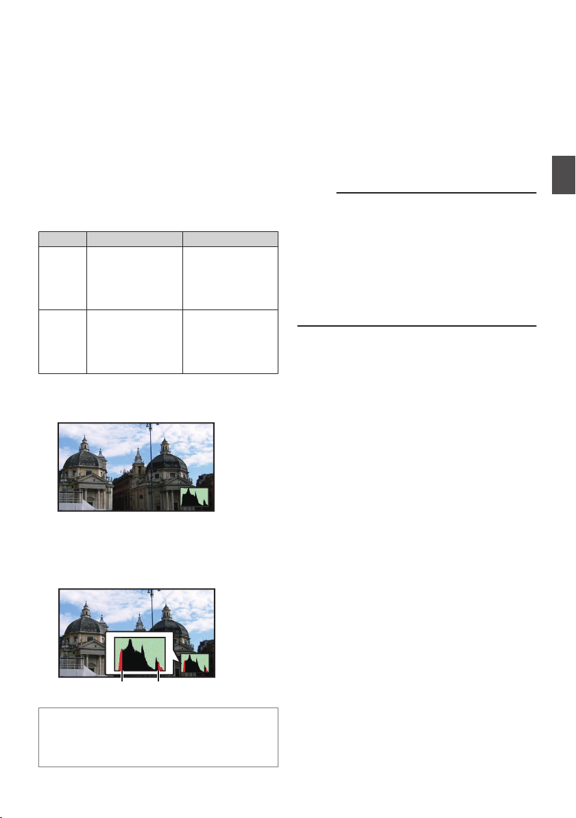
Displaying the Histogram
To p
Bottom
The histogram shows the brightness distribution,
employed mainly for checking the exposure
and is
of the image.
1
Set the histogram feature to ON.
Set
[LCD/VF
0
[Histogram] to “On”.
You can also press the user button that is
0
assigned with “Histogram”.
(
A P116 [User Switch Set Item] )
2
Set the upper and lower limits of the
histogram display.
setting, the brightness level is displayed in
After
red color.
Item Settings Options
Top Sets the maximum
Bottom Sets the minimum
o When the upper limit is set to 110% and the lower
limit to 0%
.
* The area in red is not displayed.
o When the
limit to 10%
] B [Display Type] B
brightness limit for
changing the
histogram display
color
brightness limit for
changing the
histogram display
color
upper limit is set to 90% and the lower
5% to 110% (in 5 %
increments)
0% to 105% (in 5 %
increments)
Recording Simultaneously at Two Different Definitions
By setting [System]
simultaneously at two different definitions.
When HD+Web is selected:
0
Records a high-definition (HD) file to slot A and
a web file to slot B at the same time.
Web
files
file.
Memo :
If a
recordable SD card is inserted into only one
0
of the slots, files will only be recorded to that slot.
The [Rec Mode] is fixed at “Normal”.
0
Clip Cutter Trig is disabled.
0
[Slot Mode] cannot be selected.
0
Clip Review can only be performed for slot A.
0
(“No Media” appears if there is no card in slot A
while a card is inserted into slot B.)
Playback of web files is only possible from slot
0
B when “HD+Web” is selected.
to “HD+Web”, you can record
can be used as a proxy file for the HD
Series Rec
Series Rec mode is specified in the factory
0
default.
System
([
“Series”.)
(A P160 [ Slot Mode ] )
If both the slots are loaded with recordable
0
cards, pressing the [REC]
recording only to the media in the selected slot.
When the remaining space in the selected
media runs out, recording continues by
automatically activating the media in the other
slot.
The slot mode can be identified on the status
0
screen.
] B [Record Set] B [Slot Mode] is set to
button starts
Shooting
.
How to read the histogram
The
0
The horizontal axis denotes the pixel
0
brightness.
axis denotes the number of pixels.
vertical
Displaying the Histogram
87
Page 88
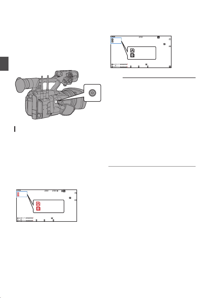
Dual Rec
100min
50min
282min
1
/60
F2. 8
AE
±0
ND1
/64
12 :34 : 56
ISO
102400
00:00 :00.00
5 . 6 f t
B 5600
K
4030 20 10 0
Lit in red
100min
50min
282min
1
/60
F2. 8
AE
±0
ND1
/64
12 :34 : 56
ISO
102400
00:00 :00.00
5 . 6 f t
B 5600
K
4030 20 10 0
White
both
the slots are loaded with recordable cards
If
0
in the Dual Rec mode ([Slot Mode] is set to
“Dual”), pressing the [REC] button starts
recording simultaneously to the media in both
the slots.
The clips recorded to the media in both the slots
0
are identical, and two clips of the same content
can be created only on this camera recorder.
(A P160 [ Slot Mode ] )
3
Stop recording.
Press the [REC] button again.
0
Recording to both slots stops, and both the
0
card slot marks turn white.
The same clips are recorded to both cards.
0
Shooting
.
Setting to Dual Rec Mode
1
Set [System] B [Record Set]
to “Dual”.
(A P160 [ Slot Mode ] )
2
Start recording.
Insert recordable media in both slots, and
0
press the [
In the Dual Rec mode, recording to the media
0
in both slots starts at the same time.
Both the card slot marks turn red, and the
0
status indicators of both the card slots also
light up in red.
REC] button.
B [Slot Mode]
.
Memo :
During recording
0
in the Dual Rec mode, both the
card slot marks light up in red.
During recording in the Dual Rec mode to two
0
cards with a different amount of remaining
space, if the space of one card runs out,
recording to both slots will stop automatically.
After recording stops, recording automatically
resumes for the card with remaining space.
Although the clips are separated in this case, the
clips can be seamlessly joined by arranging
them on the timeline of the editing software since
they are recorded seamlessly.
If the last clip on the cards that are inserted in the
0
two slots are different from each other, and the
time code operating mode is set to “Regen”, the
Regen mode for the selected card slot will be
enabled in the next recording.
0
When [WFormat] is set to “High-Speed”, “Dual”
cannot be selected.
.
88
Dual Rec
Page 89
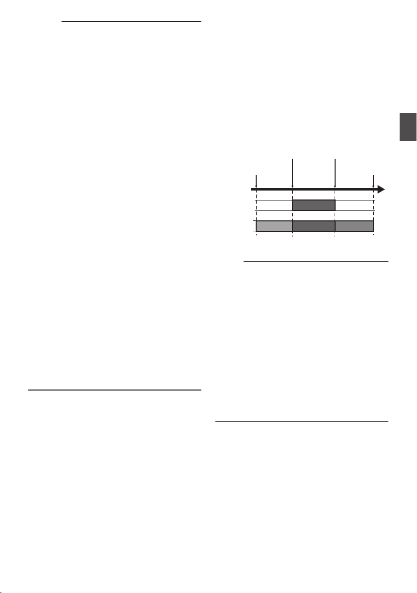
Caution :
Slot B or
[EXT.
SLOT]
Slot A
Clip 3
Clip 2
Clip 1
Clip 2
Stops
recording
to Slot B or
[EXT.SLOT]
Slot A stops
recording
Slot A starts
recording
Starts
recording
to Slot B or
[EXT.SLOT]
To perform
0
recommended that you start recording by
making use of two cards with the same capacity
and from the formatted state.
You can combine the use of the Dual Rec mode
0
with a special recording mode. While in the Dual
Rec mode, you can also set [Rec Mode] to
“Normal”, “Pre Rec”, “Clip Continuous”, “Interval
Rec”, or “Frame Rec”.
(A P91 [Special Recording] )
(A P160 [ Rec Mode ] )
When both slots are inserted with recordable
0
cards, the Dual Rec (simultaneous recording)
operation can be performed. If a recordable
media
also start recording with one card.
In the Dual Rec mode, continuous recording by
0
switching from one slot to another cannot be
performed. Continuous recording will not be
performed if a recordable media is inserted in a
slot after recording to the other slot has started.
When recording to one slot is in progress with
0
the recorder set to the Dual Rec mode, inserting
a recordable media to the other slot does not
enable the Dual Rec operation. To perform the
Dual Rec operation, stop recording temporarily
(excluding pausing recording in the Clip
Continuous Rec mode), and start again.
When one of the cards is accidentally removed
0
while recording is in progress in the Dual Rec
mode, recording to the card in the other slot will
continue. However, repair of the accidentally
removed card by the recovery function may fail.
If an error occurs on one of the cards while
0
recording is in progress in the Dual Rec mode,
recording of the erroneous card stops, while that
of the other card continues.
Operations on clips recorded in the Dual Rec
0
mode, such as clip deletion in the Media mode
or appending of OK marks, can only be
performed on the card in the selected slot.
recording in the Dual Rec mode, it is
only inserted in one of the slots, you can
is
Backup Rec
Rec
Backup
0
the media in Slot B or the [EXT.SLOT] by starting
or stopping recording to Slot B or [EXT.SLOT]
independently of control using the [REC] button.
Start or stop the recording using [System] B
0
[Record Set] B [Slot Mode] B [Backup Rec] or
press the user button that is assigned with
“Backup Trig”.
(A P
A P116 [User Switch Set Item] )
(
.
Memo :
During the Backup Rec mode (when [Slot
0
Mode] is set to “Backup
you can control recording to the 2 slots at
different timings, and backup recording can only
be performed on this camera recorder.
(A P160 [ Slot Mode ] )
You can record without worrying about missing
0
the important scenes by setting slot B or
[EXT.SLOT]
recording) and using the [REC] button to start/
stop recording of only the required scenes in slot
A.
It is recommended to use a media with high
0
capacity in slot B.
0
Backup cannot be selected when [WFormat] is
configured to “High-Speed”, “Exchange” (U
model) or “MP4” (E model).
mode enables backup recording to
160 [ Slot Mode ] )
Y” or “Backup G”),
to be always recording (backup
Shooting
Dual Rec
89
Page 90
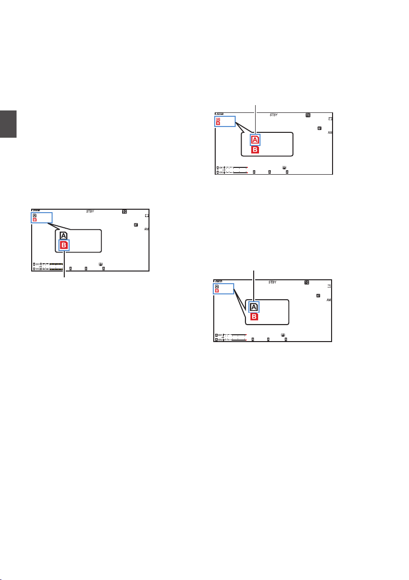
1
100min
50min
282min
1
/60
F2. 8
AE
±0
ND1
/64
12 :34 : 56
ISO
102400
00:00 :00.00
5 . 6 f t
B 5600
K
4030 20 10 0
50min
100min
Red (selected)
100min
50min
282min
1
/60
F2. 8
AE
±0
ND1
/64
12 :34 : 56
ISO
102400
00:00 :00.00
5 . 6 f t
B 5600
K
4030 20 10 0
50min
100min
Red (not selected)
100min
50min
282min
1
/60
F2. 8
AE
±0
ND1
/64
12 :34 : 56
ISO
102400
00:00 :00.00
5 . 6 f t
B 5600
K
4030 20 10 0
50min
100min
White (not selected)
Set [System] B [Record Set] B [
to “
(A P
2
Start backup recording (to Slot B or
[EXT.SLOT])
(A P160
Shooting
(
.
Backup Y” or “Backup G”.
Slot Mode]
160 [ Slot Mode ] )
The slot
0
mode can be identified on the status
screen.
Select “REC” in [System] B [Record Set] B
0
[Slot Mode] B [Backup Rec] and press the
Set button (
R).
[ Slot Mode ] )
You can also press the user button that is
0
assigned with “Backup Trig”.
A P116 [User Switch Set Item] )
Backup recording into slot B or [EXT.SLOT
0
starts.
The Slot B or [EXT.SLOT] mark turns red
0
(indicating that is is currently selected), and
the Slot B or [EXT.SLOT] status indicator
lights up in red.
3
Start normal recording (normal recording
into slot A).
Press any of the
0
Recording into the media in slot A starts.
0
(The characters “
The card
0
[REC] buttons.
RREC” appear in red.)
icon of slot A turns red (unselected
state), and the status indicator of slot A blinks
in red.
]
.
4
Stop normal recording.
Press any of the [REC]
0
Recording to slot A stops, and the card slot
0
buttons again.
mark of slot A turns white (unselected state).
0
The characters “RREC” (red) changes back
to “STBY” (white).
The status indicator of slot A goes out.
0
90
Backup Rec
.
Page 91
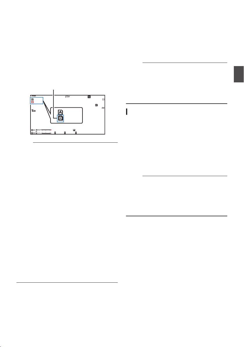
5
100min
50min
282min
1
/60
F2. 8
AE
±0
ND1
/64
12 :34 : 56
ISO
102400
00:00 :00.00
5 . 6 f t
B 5600
K
4030 20 10 0
50min
100min
White
Stop backup recording.
Select [STBY] in [System] B [Record Set] B
0
[
Slot Mode
] B [Backup Rec] and press the
Set button (R).
(A P160
[ Slot Mode ] )
You can also press the user button that is
0
assigned with “Backup Trig”.
(A P116 [User Switch Set Item] )
Recording to
0
slot B or [EXT.SLOT] stops, and
the card slot mark of slot B or [EXT.SLOT]
turns white (unselected state).
The status indicator of slot B or [EXT.SLOT]
0
lights up in green.
.
Memo :
When one
0
of the media has run out of free space
during backup recording, recording will stop
only for the card that is full.
When recording to each slot is stopped,
0
recording in the Regen mode will be enabled for
the card slot in which recording started.
When recording is started in the other slot while
0
recording to one slot, the clip being recorded is
split and simultaneous recording to the other
card starts.
When either normal recording or backup
0
recording is stopped while both are in progress,
the clip in the slot where recording is still ongoing
will be split.
Although the clips are separated during
0
recording the clips can be seamlessly joined by
arranging them on the timeline of the editing
software since they are recorded seamlessly.
Clip Cutter Trig cannot be performed during
0
backup recording.
(A P96 [Splitting the Clips Freely (Clip Cutter
Trig)] )
0
When [Slot Mode
] is configured to “Backup Y”
or “Backup G”, [Rec Mode] cannot be
configured to a setting other than “Normal”.
(A P160
[ Rec Mode ] )
Special Recording
Besides the normal recording mode, four special
recording methods are available in this camera
recorder. They are Pre Rec, Clip Continuous,
Frame Rec and Interval Rec.
Select a mode from
[System]
[Rec Mode].
(A P160 [ Rec Mode ] )
Memo :
Special recording cannot be selected when
0
[System]
B
[Record Set] B [Record Format]
[System] is set to “4K EXT (SSD)”, “HD
EXT(SSD)”, “HD+Web” or “High-Speed”.
Special recording cannot be selected when the
0
slot mode is configured to “Backup
G
”.
Pre Rec
By setting the number of seconds in the [Pre Rec
0
Time], you can start recording video and audio
before actual recording starts based on the [Pre
Rec Time] setting.
When starting actual recording while the camera
0
recorder is in Recording Standby (STBYO)
mode, you can start recording a few seconds
earlier based on the [Pre Rec Time] setting.
Using Pre Rec allows you to record a complete
0
event without missing the initial scenes even if
you start the recording late.
Memo :
Pre Rec
0
(A P160 [ Pre Rec Time ] )
Time can be set in [System] B [Record
Set] B [Rec Mode] B [Pre Rec Time].
0
When [System] is set to “4K
Fixed at “5sec”
0
When [System]
“5sec”, “10sec” or “15sec”
B [Record Set] B
Y
” or “Backup
”:
is set to “HD” or “SD”:
B
Shooting
Backup Rec
91
Page 92
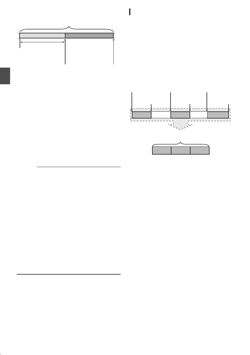
.
(Recording stops)
Press [REC]
(Recording starts)
Press [REC]
Recording starts a
number of seconds
earlier based on the
[Pre Rec Time] setting
(Recorded video and audio)
Completed Clip
(Recorded video and audio)
Completed Clip
Recording 3
Recording 2
Recording 1
Recording 3
Recording 2
Recording 1
(Recording stops)
Press and hold [REC]
(Recording pauses)
Press [REC]
(Recording pauses)
Press [REC]
(Recording resumes)
Press [REC]
(Recording resumes)
Press [REC]
(Recording starts)
Press [REC]
Shooting
1
Set [Rec Mode] to “Pre Rec”.
(A P
160 [ Rec Mode ] )
Set [System]
0
B [Record Set] B [Rec Mode
to “Pre Rec”.
0
The display changes (“STBY”
2
Press the [REC] button
to start recording in
Pre Rec mode.
0
The display
changes (“STBYO” B “RRECO”)
and the card slot status indicator lights up in
red.
Press the [REC
0
] button again to pause
recording. The display changes (“RRECO” B
“STBYO”) and the card slot status indicator
lights up in green.
Caution :
When the interval between start and stop
0
recording is short, “STBY
O” may not be
displayed immediately after recording is
complete.
“RRECO” B “STBYO” (“STBY” blinks in red) B
“STBYO” is displayed.
When the SD card becomes full during
0
recording, recording stops and
displayed.
In the following cases, video and audio before
0
the specified Pre Rec time may not be recorded
even if recording starts.
0
Immediately after power on
0
Immediately after recording stops
0
Immediately after switching from Media
mode to Camera mode
0
Immediately after setting [Rec Mode]
0
Immediately after the end of Clip Review
0
Immediately after changing file format
0
Immediately after changing video format
B “STBYO”).
“STOP” is
Clip Continuous Rec
In normal recording, when the recording stops,
0
the image,
the start till the end of the recording are recorded
as one “clip” on the SD card.
This mode allows you to consolidate several
0
rounds of “startstop recording” into one clip.
Example:
In normal recording, three clips are generated as
Recording 1, Recording 2, and Recording 3.
However, recording in this mode generates only
one clip.
]
.
1
Set “Rec Mode” to “Clip Continuous”.
(A P160 [ Rec Mode ] )
0
0
2
Start recording. (Recording 1)
0
0
audio, and accompanying data from
Set [System]
B [Record Set] B [Rec Mode
to “Clip Continuous”.
The display changes (“STBY”
Press the
[REC] button to start recording in
B “STBYL”).
Clip Continuous mode.
The display
changes (“STBYL” B “RRECL”)
and the card slot status indicator lights up in
red.
]
Special Recording
92
Page 93

3
Pause recording.
Press the
0
recording. The display changes (“RRECL” B
“STBYL” (yellow text)).
The
card
0
in red.
Memo :
When the
0
camera recorder is paused (STBYL), the
display changes (“STBYL” (yellow text) B
“STBYL” (blinking yellow text) B “STBYL”
(white text)), and a “clip” is generated. The card
slot status indicator lights up in green.
4
Resume recording. (Recording 2)
0
0
5
Pause recording.
0
0
6
Resume recording. (Recording 3)
0
0
7
Press and hold the [REC] button.
0
0
8
Press the [REC] button again.
0
0
[CANCEL] button is pressed while the
Press the
recording. The display changes (“STBYL”
(yellow text) B “RRECL”).
The
card
in red.
Press the [REC] button again to pause
recording.
“STBYL” (yellow text)).
The
card
in red.
Press the [REC] button again to resume
recording. The display changes (“STBYL”
(yellow text) B “RRECL”).
The
card
in red.
Recording stops and the display changes
(“RRECL” B “STBYL”). A
The card slot status indicator lights up in
green.
The
display
and the card slot status indicator lights up in
red.
A new “clip” is generated from here.
button again to pause
[REC]
slot status indicator remains lighted
button again to resume
[REC]
slot status indicator remains lighted
The display changes (“RRECL” B
slot status indicator remains lighted
slot status indicator remains lighted
“clip” is generated.
changes (“STBYL” B “RRECL”)
Memo :
The following operations cannot be performed
0
while recording
0
Clip Review operation
(A P86 [Viewing Recorded Videos
Immediately (Clip Review)] )
0
Switching SD card slots
0
Switching operation mode
(
A P24 [Operation Modes] )
Files are split into sizes of 4 GB (or 30 minutes)
0
regardless of the menu settings.
Caution :
Do not remove the SD card during recording
0
(RRECL,
yellow text).
To remove
0
mode, press the [CANCEL] button, check that
“STBYL” (white text) is displayed and the card
slot status indicator lights up in green before you
remove the card.
To remove
0
mode, press the [CANCEL] button, check that
“STBYL” (white text) is displayed and the card
slot status indicator lights up in green before you
remove the card.
When the SD card becomes full during
0
recording, recording stops and “STOP
displayed.
When the [POWER ON/OFF] switch is turned off
0
during recording or recording pause, recording
stops and power is cut off after a clip is
generated.
If the power is cut off due to low battery power,
0
a proper clip may not be generated.
is paused (STBYL, yellow text).
text) or recording pause (STBYL,
red
the SD card in the “Clip Continuous”
the SD card in the “Clip Continuous”
” is
Shooting
Special Recording
93
Page 94
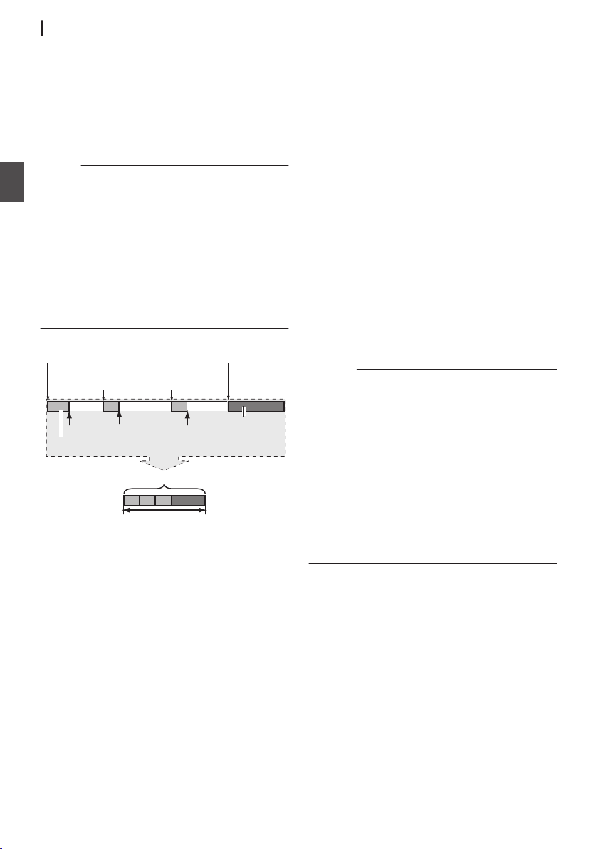
Frame Rec
Specific amount of data
Actual clips recorded to the media
Records number of frames specified in [Rec Frames]
(Padding data)
Normal recording
Paus ePaus ePaus e
Recording resumes
Recording resumes
Press [REC]Press [REC]
(Frame Rec stops)(Frame Rec starts)
Press and hold [REC]Press [REC]
In normal recording, when the recording stops, the
image and
end of the recording are recorded as one “clip” on
the SD card.
In this mode, recording starts with every press of
the [REC] button, and only the specified number of
frames is recorded.
The recording can be written to the media as a
single clip until it is stopped.
Memo :
0
0
Shooting
0
0
.
1
accompanying data from the start till the
Audio will not be recorded.
Until a specified amount of recordings is
accumulated, the file cannot be written to the
media.
If the specified amount is not reached when
recording is stopped, normal recording is
performed and frames are added to the ending
clip until the amount is reached. (Padding)
of the
After the specified number of frames is recorded
and written to the media, recording will be
performed until the same number is
accumulated again.
Set [Rec Mode] to “Frame Rec”.
Set [System] B [Record Set] B [Rec Mode
0
to “Frame Rec”.
(A P160 [ Rec Mode ] )
0
The display changes (“STBY
” B “STBYM”).
2
Set the number of frames to record in [Rec
Frames].
To configure the setting, go to [System]
0
[Record Set] B [Rec Mode] B [Rec Frames].
(A P
160 [ Rec Frames ] )
3
Start recording.
Press the [REC] button to record only the
0
number of frames specified in [Rec Frames]
and pause.
0
The display changes (
“STBYM
B “STBYM” (yellow text)).
The card slot status indicator lights up in
0
green.
4
Repeat Frame Rec.
Press the
0
button again to record only
[REC]
the number of frames specified in [Rec
Frames] and pause.
0
The display changes (“STBYM” B “RRECM”
B “STBYM” (yellow text)).
Frame Rec continues until the recording is
0
stopped (step 5).
5
Press and hold the [REC] button.
The card slot status indicator lights up in
0
green.
Caution :
Do not remove the SD card during recording
0
(“RRECM”, red text) or recording pause
(“STBYM”, yellow text).
To remove
0
the SD card during Frame Rec, press
the [CANCEL] button, check that “STBYM”
(white text) is displayed and the card slot status
indicator lights up in green before you remove
the card.
When [TC/UB] B [TC Generator] is set to “Free
0
Run” or “Free Run (Ext)
”, the time code will be
recorded in “Rec Run”.
Audio cannot be recorded. The audio level
0
meter is grayed out.
(A P167 [Audio Level Meter] )
]
B
” B “RRECM”
94
Special Recording
Page 95
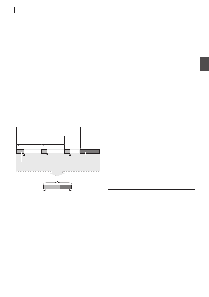
Interval Rec
Specific amount of data
Actual clips recorded to the media
Records number of frames specified in [Rec Frames]
(Padding data)
Normal recording
Paus ePaus ePause
[Rec Interval][Rec Interval]
Recording resumes
Recording resumes
(Interval Rec stops)(Interval Rec starts)
Press [REC]Press [REC]
In normal recording, when the recording stops, the
image and
end of the recording are recorded as one “clip” on
the SD card.
In this mode, recording and pause are performed
repeatedly at the specified time interval. Only the
specified number of frames is recorded.
The recording can be written to the media as a
single clip until it is stopped.
Memo :
0
0
0
0
accompanying data from the start till the
Audio will not be recorded.
Until a specified amount of recordings is
accumulated, the file will not be written to the
media.
After the
specified number of frames is recorded
and written to the media, recording will be
performed until the same number is
accumulated again.
If the specified amount is not reached when
recording is stopped, normal recording is
performed and frames are added to the ending
of the clip until the amount is reached. (Padding)
3
Set the time interval to start recording in
[
Interval Rec
].
To configure the setting, go to [System] B
[Record Set]
B [Rec Mode] B [Rec Interval].
(A P160 [ Rec Interval ] )
4
Start recording.
Press the
0
[REC
] button to record only the
number of frames specified in [Rec Frames]
and pause.
After the specified time in [Rec Interval] has
0
passed, recording starts again to record only
the number of frames specified in [Rec
Frames] and pause.
Interval Rec continues until the recording is
0
stopped.
The display changes (“STBYN” B “RRECN”
B “STBYN” (red text) B “RRECN” B
“STBYN” (red text)).
The
0
5
Press the [REC] button.
The card slot status indicator lights up in
0
slot status indicator lights up in red.
card
green.
0
The display becomes “STBYN
”.
Caution :
Do not remove the SD card during recording
0
(RRECN, red text) or recording pause (STBYN,
yellow text).
To remove the SD card during Interval Rec,
0
press the
[CANCEL] button, check that “STBYN”
(white text) is displayed and the card slot status
indicator lights up in green before you remove
the card.
When [TC/UB] B [TC Generator] is set to “Free
0
Run” or “Free Run (Ext)
”, the time code will be
recorded in “Rec Run”.
Audio cannot be recorded. The audio level
0
meter is grayed out.
(A P167 [Audio Level Meter] )
Shooting
.
1
Set [Rec Mode] to “Interval Rec”.
Set [System] B [Record Set] B [
0
to “Interval Rec”.
A P160 [ Rec Mode ] )
(
0
The display changes (“STBY”
2
Set the number of frames to record in [Rec
Frames].
To configure the setting, go to [System
[Record Set]
B [Rec Mode] B [Rec Frames].
(A P160 [ Rec Frames ] )
Rec Mode]
B “STBYN”).
] B
Special Recording
95
Page 96
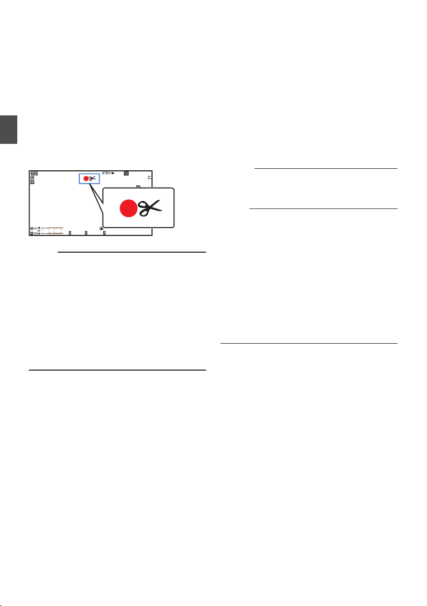
Splitting the Clips Freely
100min
50min
282min
1
/60
F2. 8
AE
±0
ND1
/64
12 :34 : 56
ISO
102400
00:00 :00.00
5 . 6 f t
B 5600
K
4030 20100
(Clip Cutter Trig)
split the clips freely without having to stop
You can
recording during shooting.
1
Assign the “Clip Cutter Trig” function to
any of the user buttons.
(A P
46 [Assignment of Functions to User
Buttons] )
2
Shooting
.
Memo :
0
0
0
0
0
the user button that is assigned with
Press
“Clip Cutter Trig”
during shooting.
A clip cut icon (Q) appears on the display
screen for 3 seconds, and the clip is split.
Clips cannot be split again for a few seconds
after the operation is performed.
This item cannot be used when [
set to “Backup Y” or “Backup G”.
This item cannot be used when [
set to a value other than “Normal” or “Pre Rec”.
(A P160 [ Rec Mode ] )
The split clips are recorded seamlessly without
interruptions in the video.
When “4K EXT (SSD)”, Exchange (U model) or
MP4 (E model) is selected, the clip cutter
function cannot be used.
Slot Mode] is
Rec Mode] is
Configuring Infrared Recording
This camera recorder comes with a infrared
recording mode
Using infrared illumination allows images to be
captured naturally in a pitch-dark environment. It is
recommended for observation of animals without
alerting them or for natural facial expressions
without firing glaring flash light at the subject.
1
Set the [FULL AUTO] switch to “OFF”.
2
Set [Camera
A “I” icon appears.
Caution :
Do not use infrared recording for capturing
0
strong light sources or heat sources. Doing so
may damage the camera recorder.
Memo :
The settings are fixed as followed when it is
0
configured to “On”.
0
Manual focus
0
ND Filter“OFF”
0
[Camera Function]
and [MF Assist] appear as “---”.
0
All items other than [Color Space] and
[Reverse Picture
appear as “---”.
The zoom and focus positions will be initialized
0
after the settings are changed.
When [Infrared] is configured to “On”, if the type
0
of light source changes after focus is
established, the image may go out of focus.
that is suitable for night recording.
Function]
B [Infrared] to “On”.
B [Focus] B [AF Assist]
] under [Camera Process]
Splitting the Clips Freely (Clip Cutter Trig)
96
Page 97
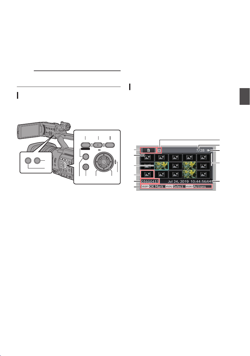
Playing Recorded Clips
CANCEL
MENU/THUMB
AE LEVEL
ONLINE/3
OIS/2
FOCUS ASSIST/1
TIME CODE
DISPLAY STATUS
H
I
AD B C
EFG
A
J
H
C
B
G
E
D
F
I
K
To play back clips recorded in a recording media,
switch to the Media mode.
Press and
Camera mode to enter the Media mode. A
thumbnail screen of the clips recorded on the
recording media is displayed.
You can play back the selected clip on the
thumbnail screen.
Memo :
0
Operation Buttons
Use the operation buttons on the side control panel
or front side of the camera recorder to operate the
thumbnail screen.
.
A
B
C
D
E
hold the [MODE] selection button in the
When a recording media without any clips is
inserted, “No Clips” is displayed.
[MENU/THUMB]
Displays the menu.
0
Press this button to close the menu screen
0
Button
during menu display and return to the
thumbnail screen.
Cross-Shaped Button (JKHI)
Moves the cursor.
Set (Play) Button
Sets the values and items. (Confirm)
0
Plays back the selected clip.
0
[CANCEL] (Stop) Button
Cancels settings and returns to the previous
screen.
[FOCUS ASSIST/1] Button
OK mark of the clip selected by
Switches
0
the
the cursor.
If an OK mark has been appended, it will be
0
deleted. Otherwise, an OK mark will be
appended.
F
[OIS/2] Button
Switches the selection status of the clip
0
selected by the cursor.
Clips being selected are displayed with
0
check mark.
G
[ONLINE/3] Button
Enters the action selection screen.
H
[DISPLAY] Button
Switches between the “Standard Screen” and
“Detailed Screen
I
[STATUS] Button
”.
Displays the media information screen.
Thumbnail Screen
“Standard Screen
0
available.
Use the [DISPLAY] button to switch between the
screens.
Thumbnails are displayed in order of recording
0
from the oldest to most recent.
Standard screen
.
A
Recording Media Information
Displays the
0
the selected recording media or the status of
the write-protect switch for the SD card.
The inserted recording media will not be
0
displayed if [System] is different.
Use the [SLOT SEL] button to switch
0
between slots A and B. Clips from different
slots cannot be displayed at the same time.
:
W z
:
S
:
G
” and “Detailed Screen
status when repair is required for
Write-protect switch of the SD card
in slot A is set.
SD card in slot B needs to be
restored or formatted, or is an
unsupported SD card.
SSD media in [EXT.SLOT]
” are
Playback
Playing Recorded Clips
97
Page 98
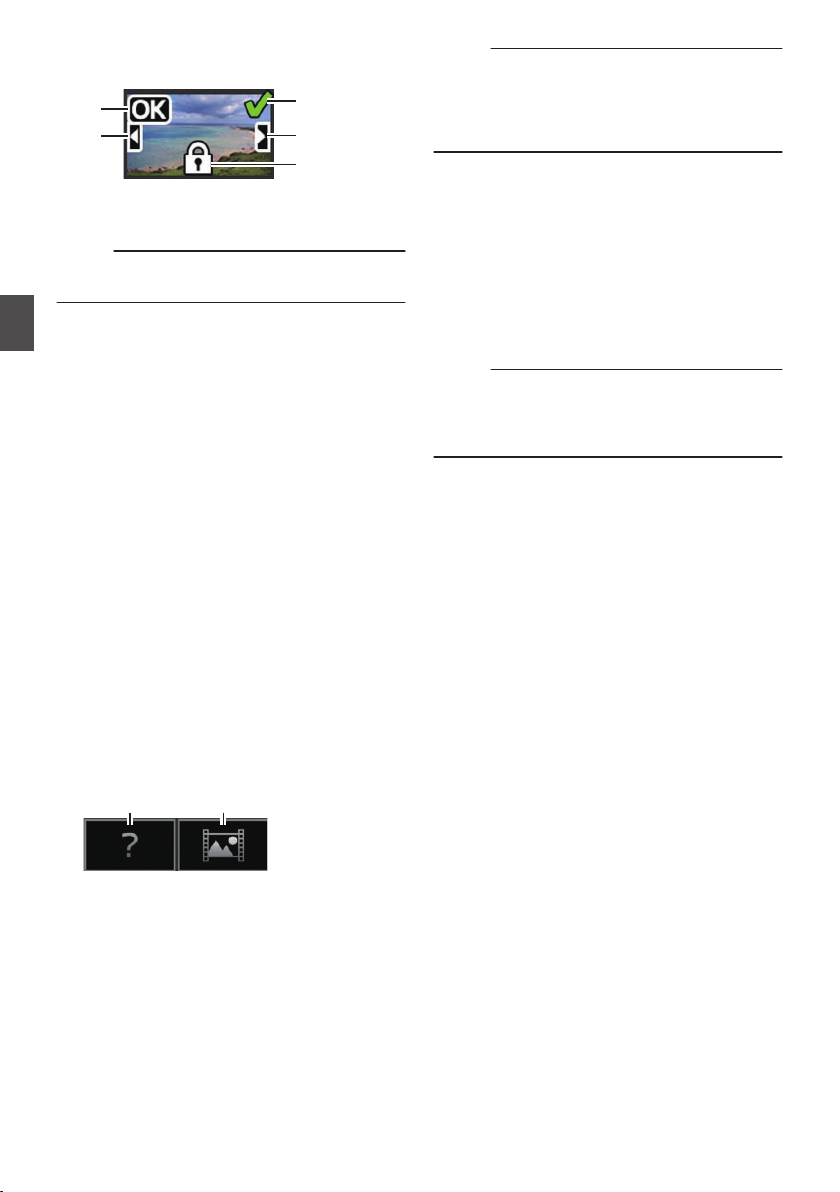
B
A
B
D
E
C
A B
Clip Mark
Displays the clip information (properties).
.
OK Mark
A
Clip is appended with OK mark.
Memo :
Clips appended with OK marks cannot be
0
deleted on the camera recorder.
Continued From Mark
B
Playback
This mark indicates that the current clip is
continued from another SD card when
recording is divided and made on several SD
cards.
Uneditable Mark
C
This mark indicates that an OK mark cannot
0
appended
be
the clip cannot be deleted.
Continue Mark
D
mark
This
clip is continued to another SD card when
recording is divided and made on several SD
cards.
Check Mark
E
A green check mark is displayed when the
0
clip is selected.
Magenta and gray check marks are
0
displayed in multiple selection mode.
(A P104 [Selecting and Performing
Operations on Multiple Clips] )
C
Cursor
Clip to be worked on. Use the cross-shaped
JKHI) to move the cursor.
button (
D
Thumbnail Substitution Display
to or deleted from the clip, and
indicates that recording of the current
Memo :
This is dependent on the [System], [Format],
0
[Resolution], [Frame Rate
settings in the [System] B [Record Set] B
[Record Format] menu.
(A P156 [ System ] )
E
Clip Name
name (clip number) of the selected clip
The file
is displayed.
F
Operation Guide
Displays a guide for the current operation
0
buttons.
The action selection screen is displayed
0
when the [ONLINE/3
(
A P99 [Actions] )
G
Recording Start Time
Displays the recording start time of the clip.
Memo :
The date/time display is dependent on the
0
settings in
(A P155 [ Date Style ] )
(
A P156 [ Time Style ] )
H
Scroll Bar
0
0
0
I
Remaining Battery Power
(A P37 [Power Status Display] )
J
Number of Clips
0
0
K
Network Connection Icon
0
[System] B [Date Style]/[Time Style].
Indicates the scroll position.
Black space below the scroll bar (white)
indicates that there are more pages.
When the scroll bar (white) is at the bottom,
this indicates the last page.
of the clips are selected, the “running
If none
number/total number of clips” of the clip to be
displayed appears.
Even if only one clip is selected, the number
of selected clips in the current slot is
displayed.
The network connection status is displayed.
] and [Bit Rate]
] button is pressed.
.
A clip with corrupted management information.
A
It cannot be played back even if you press the
Set (Play) button.
that cannot be played back nor displayed
clip
A
B
in thumbnail with the current video format
settings.
It cannot be played back even if you press the
Set (Play) button.
98
Playing Recorded Clips
Page 99
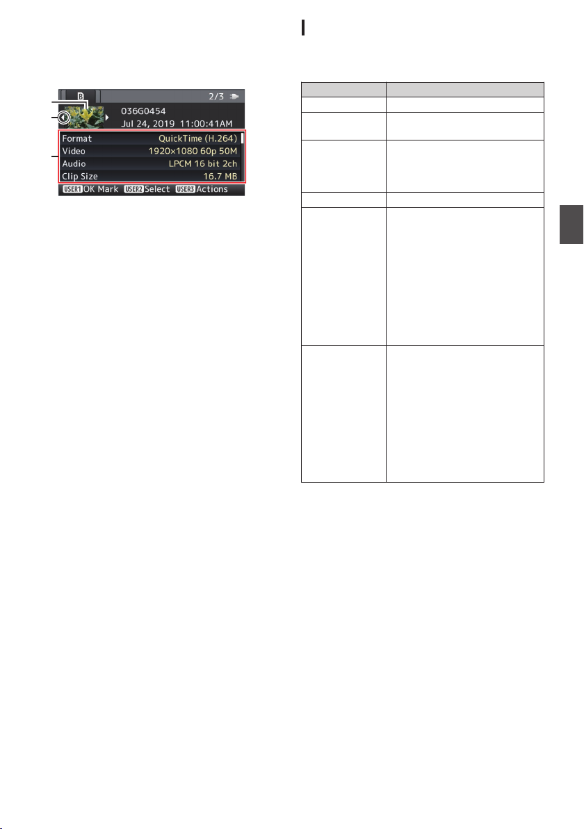
Detailed screen
C
B
A
* Items that
will not be described. Refer to “[Standard
screen] (A P 97)”.
.
A
Thumbnail
Thumbnail of the clip selected by the cursor.
Use the
cursor.
B
Scroll Mark (DE)
0
0
0
C
Metadata
Metadata of the clip pointed by the cursor.
You can use the cross-shaped button (JK) to
scroll.
are common with the Standard screen
cross-shaped button (HI) to move the
If there are previous clips, D appears on the
left.
If there
are more clips, E appears on the right.
The marks will not be displayed if there are
no clips before and after the current clip.
Actions
The action selection screen is displayed when the
[ONLINE/3] button is pressed.
The following operations can be performed.
Item Description
Select All Clips Selects all clips.
Select OK
Marked
Select Range Specifies the range when
Deselect All
Add OK Mark Appends an OK mark.
Delete OK Mark Deletes the OK mark.
Selects all clips appended with
OK mark.
selecting multiple clips.
104 [Selecting Multiple
(A P
Clips Randomly] )
Clears all clip selections.
This Clip:
0
Appends an OK mark to the
clip pointed by the cursor.
Selected Clips:
0
Appends an OK mark to the
clips selected (appended
with check mark).
All Clips:
0
Appends an OK mark to all
clips.
This Clip:
0
Deletes the OK mark of the
clip pointed by the cursor.
Selected Clips:
0
Deletes the OK mark of the
clips selected (appended
with check mark).
All Clips:
0
Deletes the OK mark of all
clips.
Playback
Playing Recorded Clips
99
Page 100
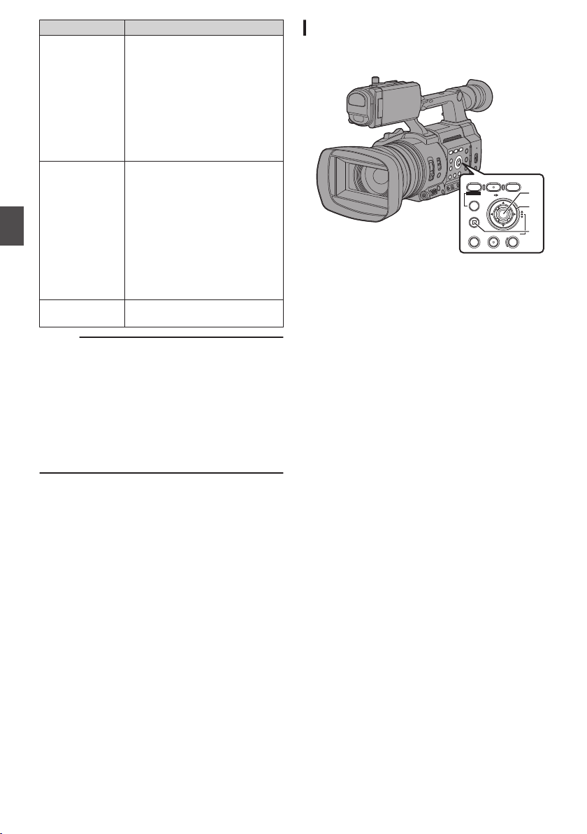
Item Description
SHUTTERWHT BALGAIN
CANCEL
MENU/THUMB
AE LEVEL
ONLINE/3
OIS/2
FOCUS ASSIST/1
TIME CODE
C
B
A
FTP Upload Uploads a clip to the FTP server.
This Clip:
0
Uploads the clip pointed by
the cursor.
Selected Clips:
0
Uploads the clips selected
(appended with check
mark).
All Clips:
0
Uploads all clips.
Delete Clips Deletes clip. However, clips with
OK mark cannot be deleted.
This Clip:
0
Deletes the clip pointed by
the cursor.
Selected Clips:
0
Playback
Deletes the clips selected
(appended with check
mark).
All Clips:
0
Deletes all clips.
Trim This Clip Trims the clip pointed by the
cursor.
Memo :
The object
0
of action is the clip of the current slot
being displayed.
[Selected Clips] cannot be performed if there are
0
no selected (appended with check mark) clips.
[This Clip] cannot be performed if there are more
0
than one selected (appended with check mark)
clips.
If the write-protect switch of an SD card is set,
0
OK mark cannot be appended or deleted, and
the clips cannot be deleted and trimmed.
Playing back
Use the operation buttons on the side control panel
of the camera recorder to play back.
.
A
Set Button (R)
Plays back/pauses the clip pointed by the
0
cursor.
0
You
to perform frame-by-frame forward playback
during pause mode.
B
Cross-shaped Button (JKH I)
0
[J/K] Button:
Skips in the reverse or forward direction.
0
[H/I] Button:
C
[CANCEL] Button
Stops playback.
1
In the thumbnail screen, move the cursor to
the clip to be played back.
Move the cursor to the clip to be played back
using the cross-shaped button (JKH I).
2
Press the Set button (R).
Playback of the selected clip starts.
press the cross-shaped button (HI)
can
0
During Playback:
Fast forwards in the reverse or forward
direction.
0
While paused:
Frame-by-frame playback in the reverse
or forward direction.
Playing Recorded Clips
100
Audio Output during Playback
You can confirm the playback sound from the
0
monitor speaker, or the headphone connected
to the [x] terminal. When a headphone is
connected
to
the [x] terminal, sound cannot be
output from the monitor speaker.
(A P
183 [Connect the headphone] )
Adjust the volume of the monitor speaker and
0
headphone using the [MONITOR +/-] volume
adjustment button on the LCD monitor section
of the camera recorder.
 Loading...